

ViewSonic PJD7383i, PJD7583wi, PJD7583w, VS13339, VS13340 User Manual

ViewSonic
®
Model No. : VS13339
VS13340
PJD7383/ PJD7383i
PJD7583w/PJD7583wi
DLP Projector
- User Guide
- Guide de l’utilisateur
- Bedienungsanleitung
- Guía del usuario
- Guida dell’utente
- Guia do usuário
- Användarhandbok
- Käyttöopas
- Podręcznik użytkownika
- Pyководство пользователя
- Kullanιcι kιlavuzu
- 使用手冊(繁中)
- 使用手册 (简体)
- 사용자 안내서
IMPORTANT: Please read this User Guide to obtain important
information on installing and using your product in a safe
manner, as well as registering your product for future service.
Warranty information contained in this User Guide will describe
your limited coverage from ViewSonic Corporation, which is
also found on our web site at http://www.viewsonic.com in
English, or in specic languages using the Regional selection
box in the upper right corner of our website.
“Antes de operar su equipo lea cuidadosamente las
instrucciones en este manual”
i
Compliance Information
FCC Statement
This device complies with part 15 of FCC Rules. Operation is subject to the following two conditions:
(1) this device may not cause harmful interference, and (2) this device must accept any interference
received, including interference that may cause undesired operation.
This equipment has been tested and found to comply with the limits for a Class B digital device,
pursuant to part 15 of the FCC Rules. These limits are designed to provide reasonable protection
against harmful interference in a residential installation. This equipment generates, uses, and can
radiate radio frequency energy, and if not installed and used in accordance with the instructions, may
cause harmful interference to radio communications. However, there is no guarantee that interference
will not occur in a particular installation. If this equipment does cause harmful interference to radio
or television reception, which can be determined by turning the equipment off and on, the user is
encouraged to try to correct the interference by one or more of the following measures:
• Reorient or relocate the receiving antenna.
• Increase the separation between the equipment and receiver.
• Connect the equipment into an outlet on a circuit different from that to which the receiver is
connected.
• Consult the dealer or an experienced radio/TV technician for help.
Warning: You are cautioned that changes or modications not expressly approved by the party
responsible for compliance could void your authority to operate the equipment.
For Canada
• This Class B digital apparatus complies with Canadian ICES-003.
• Cet appareil numérique de la classe B est conforme à la norme NMB-003 du Canada.
CE Conformity for European Countries
The device complies with the EMC Directive 2004/108/EC and Low Voltage Directive
2006/95/EC.
Following information is only for EU-member states:
The mark is in compliance with the Waste Electrical and Electronic Equipment Directive
2002/96/EC (WEEE).
The mark indicates the requirement NOT to dispose the equipment including any spent or
discarded batteries or accumulators as unsorted municipal waste, but use the return and
collection systems available.
If the batteries, accumulators and button cells included with this equipment, display the
chemical symbol Hg, Cd, or Pb, then it means that the battery has a heavy metal content of
more than 0.0005% Mercury or more than, 0.002% Cadmium, or more than 0.004% Lead.
Industry Canada Notice
This wireless module device complies with Canadian RSS-210.To prevent radio interference to the
licensed service, this device is intended to be operated indoors and away from windows to provide
maximum shielding. Equipment (or its transmitting antenna) that is installed outdoors is subject to
licensing. The installer of this radio equipment must ensure that the antenna is located or pointed such
that it does not emit RF eld in excess of Health Canada limits for the general population; consult
Safety Code 6, obtainable from Health Canada’s web site www.hc-sc.gc.ca/rpb.

ii
Important Safety Instructions
1. Read these instructions.
2. Keep these instructions.
3. Heed all warnings.
4. Follow all instructions.
5. Do not use this unit near water.
6. Clean with a soft, dry cloth.
7. Do not block any ventilation openings. Install the unit in accordance with the
manufacturer’s instructions.
8. Do not install near any heat sources such as radiators, heat registers, stoves, or other
devices (including ampliers) that produce heat.
9. Do not defeat the safety purpose of the polarized or grounding-type plug. A polarized plug
has two blades with one wider than the other. A grounding type plug has two blades and a
third grounding prong. The wide blade and the third prong are provided for your safety. If
the provided plug does not t into your outlet, consult an electrician for replacement of the
obsolete outlet.
10. Protect the power cord from being walked on or pinched particularly at plugs. Convenience
receptacles and the point where they exit from the unit. Be sure that the power outlet is
located near the unit so that it is easily accessible.
11. Only use attachments/accessories specied by the manufacturer.
12. Use only with the cart, stand, tripod, bracket, or table specied by the
manufacturer, or sold with the unit. When a cart is used, use caution when moving
the cart/unit combination to avoid injury from tipping over.
13. Unplug this unit when unused for long periods of time.
14. Refer all servicing to qualied service personnel. Servicing is required when the unit has
been damaged in any way, such as: if the power-supply cord or plug is damaged, if liquid is
spilled onto or objects fall into the unit, if the unit is exposed to rain or moisture, or if the
unit does not operate normally or has been dropped.
iii
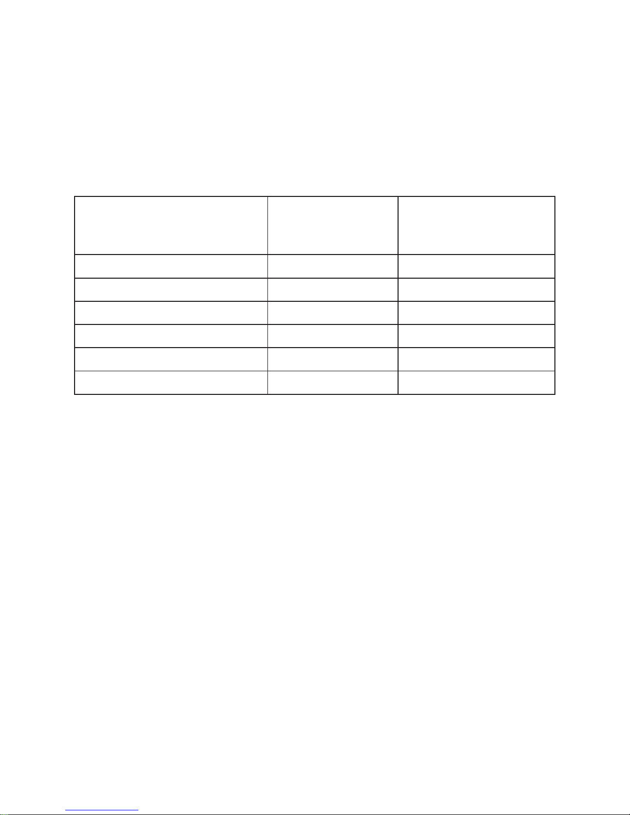
Declaration of RoHS Compliance
This product has been designed and manufactured in compliance with Directive 2002/95/EC of
the European Parliament and the Council on restriction of the use of certain hazardous substances
in electrical and electronic equipment (RoHS Directive) and is deemed to comply with the
maximum concentration values issued by the European Technical Adaptation Committee (TAC)
as shown below:
Substance
Proposed Maximum
Concentration
Actual Concentration
Lead (Pb) 0.1% < 0.1%
Mercury (Hg) 0.1% < 0.1%
Cadmium (Cd) 0.01% < 0.01%
Hexavalent Chromium (Cr6+) 0.1% < 0.1%
Polybrominated biphenyls (PBB) 0.1% < 0.1%
Polybrominated diphenyl ethers (PBDE) 0.1% < 0.1%
Certain components of products as stated above are exempted under the Annex of the RoHS
Directives as noted below:
Examples of exempted components are:
1. Mercury in compact uorescent lamps not exceeding 5 mg per lamp and in other lamps not
specically mentioned in the Annex of RoHS Directive.
2. Lead in glass of cathode ray tubes, electronic components, uorescent tubes, and electronic
ceramic parts (e.g. piezoelectronic devices).
3. Lead in high temperature type solders (i.e. lead-based alloys containing 85% by weight or
more lead).
4. Lead as an allotting element in steel containing up to 0.35% lead by weight, aluminium
containing up to 0.4% lead by weight and as a cooper alloy containing up to 4% lead by
weight.

1
Copyright Information
Copyright © ViewSonic® Corporation, 2011. All rights reserved.
Macintosh and Power Macintosh are registered trademarks of Apple Inc.
Microsoft, Windows, Windows NT, and the Windows logo are registered trademarks of
Microsoft Corporation in the United States and other countries.
ViewSonic, the three birds logo, OnView, ViewMatch, and ViewMeter are registered trademarks
of ViewSonic Corporation.
VESA is a registered trademark of the Video Electronics Standards Association. DPMS and DDC
are trademarks of VESA.
PS/2, VGA and XGA are registered trademarks of International Business Machines Corporation.
Disclaimer: ViewSonic Corporation shall not be liable for technical or editorial errors or
omissions contained herein; nor for incidental or consequential damages resulting from
furnishing this material, or the performance or use of this product.
In the interest of continuing product improvement, ViewSonic Corporation reserves the right to
change product specications without notice. Information in this document may change without
notice.
No part of this document may be copied, reproduced, or transmitted by any means, for any
purpose without prior written permission from ViewSonic Corporation.
Product Registration
To meet your future needs, and to receive any additional product information as it becomes
available, please register your product on the Internet at: www.viewsonic.com. The ViewSonic
®
Wizard CD-ROM also provides an opportunity for you to print the registration form, which you
may mail or fax to ViewSonic.
For Your Records
Product Name:
Model Number:
Document Number:
Serial Number:
Purchase Date:
PJD7383/PJD7383i/PJD7583w/PJD7583wi
ViewSonic DLP Projector
VS13339/VS13340
PJD7383/7383i/7583w/7583wi_UG_ENG
Rev. 1C 03-15-11
_______________________________
_______________________________
Product disposal at end of product life
The lamp in this product contains mercury which can be dangerous to you and the environment.
Please use care and dispose of in accordance with local, state or federal laws.
ViewSonic respects the environment and is committed to working and living green. Thank you
for being part of Smarter, Greener Computing. Please visit ViewSonic website to learn more.
USA & Canada: http://www.viewsonic.com/company/green/recycle-program/
Europe: http://www.viewsoniceurope.com/uk/support/recycling-information/
Taiwan: http://recycle.epa.gov.tw/recycle/index2.aspx

Table of contents2
Table of contents
Important safety
instructions .......................3
Introduction......................5
Projector features ................................. 5
Shipping contents.................................6
Projector exterior view.........................7
Controls and functions ......................... 8
Positioning your
projector..........................12
Choosing a location............................12
Projection dimensions........................ 13
Connection ......................15
Connecting a computer or monitor ....16
Connecting Video source devices ...... 17
Playing sound through the projector .. 19
Operation ........................21
Starting up the projector..................... 21
Using the menus................................. 23
Utilizing the password function ......... 24
Switching input signal........................ 26
Adjusting the projected image ...........27
Magnifying and searching for details. 29
Selecting the aspect ratio ...................29
Optimizing the image......................... 31
Hiding the image................................35
Locking control keys.......................... 35
Freezing the image............................. 36
Operating in a high altitude
environment .......................................36
Creating your own startup screen....... 37
Setting the presentation timer ............38
Controlling the projector through
a LAN environment ........................... 39
Displaying images through
vsPresenter......................................... 46
Displaying pictures with a USB
storage device .................................... 50
Using the PointBlank pen
(PJD7383i/PJD7583wi only)............. 53
Using the projector in standby
mode .................................................. 57
Shutting down the projector .............. 58
Menu operation.................................. 59
Maintenance ...................68
Care of the projector .......................... 68
Lamp information.............................. 69
Troubleshooting .............75
Specifications ..................76
Projector specifications...................... 76
Dimensions ........................................ 77
Ceiling mount installation ................. 77
Timing chart ...................................... 77
Copyright and Regulation
information .....................79
Appendix.........................80
IR control table .................................. 80
RS232 command table....................... 80

Important safety instructions 3
Important safety instructions
Your projector is designed and tested to meet the latest standards for safety of information
technology equipment. However, to ensure safe use of this product, it is important that you
follow the instructions mentioned in this manual and marked on the product.
Safety Instructions
1. Please read this manual before you operate your projector. Save it for future
reference.
2. Do not look straight at the projector lens during operation. The intense light beam
may damage your eyes.
3. Refer servicing to qualified service personnel.
4. Always open the lens shutter or remove the lens cap when the projector lamp is
on.
5. In some countries, the line voltage is NOT stable. This projector is designed to operate
safely within a mains voltage between 100 to 240 volts AC, but could fail if power
cuts or surges of 10 volts occur. In areas where the mains voltage may fluctuate
or cut out, it is recommended that you connect your projector through a power
stabilizer, surge protector or uninterruptible power supply (UPS).
6. Do not block the projection lens with any objects when the projector is under
operation as this could cause the objects to become heated and deformed or even
cause a fire. To temporarily turn off the lamp, press BLANK on the projector or
remote control.
7. The lamp becomes extremely hot during operation. Allow the projector to cool for
approximately 45 minutes prior to removing the lamp assembly for replacement.
8. Do not operate lamps beyond the rated lamp life. Excessive operation of lamps
beyond the rated life could cause them to break on rare occasions.
9. Never replace the lamp assembly or any electronic components unless the projector is
unplugged.
10. Do not place this product on an unstable cart, stand, or table. The product may fall,
sustaining serious damage.
11. Do not attempt to disassemble this projector. There are dangerous high voltages inside
which may cause death if you should come into contact with live parts. The only user
serviceable part is the lamp which has its own removable cover.
Under no circumstances should you ever undo or remove any other covers. Refer
servicing only to suitably qualified professional service personnel.
12. Do not place this projector in any of the following environments.
- Space that is poorly ventilated or confined. Allow at least 50 cm clearance from walls
and free flow of air around the projector.
- Locations where temperatures may become excessively high, such as the inside of a
car with all windows rolled up.
- Locations where excessive humidity, dust, or cigarette smoke may contaminate optical
components, shortening the projector's life span and darkening the picture.
- Locations near fire alarms
- Locations with an ambient temperature above 40°C / 104°F
- Locations where the altitudes are higher than 3000 m (10000 feet).

Important safety instructions4
13. Do not block the ventilation holes. If the ventilation holes are seriously obstructed,
overheating inside the projector may result in a fire.
- Do not place this projector on a blanket, bedding or any other soft surface.
- Do not cover this projector with a cloth or any other item.
- Do not place inflammables near the projector.
14. Always place the projector on a level, horizontal surface during operation.
- Do not use if tilted at an angle of more than 10 degrees left to right, nor at angle of
more than 15 degrees front to back. Using the projector when it is not fully horizontal
may cause a malfunction of, or damage to, the lamp.
15. Do not stand the projector on end vertically. Doing so may cause the projector to fall
over, causing injury or resulting in damage to the projector.
16. Do not step on the projector or place any objects upon it. Besides probable physical
damage to the projector, doing so may result in accidents and possible injury.
17. Do not place liquids near or on the projector. Liquids spilled into the projector may
cause it to fail. If the projector does become wet, disconnect it from the power
supply's wall socket and call your local service center to have the projector serviced.
18. This product is capable of displaying inverted pictures for ceiling mount installation.
Use only qualified ceiling mount kit for mounting the projector and ensure it is
securely installed.
19. When the projector is under operation, you may sense some heated air and odor from
its ventilation grill. It is a normal phenomenon and not a product defect.
20. Do not use the Security bar for transporting or installation. It should be used with a
commercially available theft prevention cable.
Safety instructions for ceiling mounting of the
projector
We want you to have a pleasant experience using your projector, so we need to bring this
safety matter to your attention to prevent damage to person and property.
If you intend to mount your projector on the ceiling, we strongly recommend that you use a
proper fitting projector ceiling mount kit and that you ensure it is securely and safely
installed.
If you use an inappropriate projector ceiling mount kit, there is a safety risk that the
projector may fall from the ceiling due to an improper attachment through the use of the
wrong gauge or length screws.
You can purchase a projector ceiling mount kit from the place you purchased your projector.
We recommends that you also purchase a separate Kensington lock compatible security
cable and attach it securely to both the Kensington lock slot on the projector and the base of
the ceiling mount bracket. This will perform the secondary role of restraining the projector
should its attachment to the mounting bracket become loose.

Introduction 5
Introduction
Projector features
The projector integrates high-performance optical engine projection and a user-friendly
design to deliver high reliability and ease of use.
The projector offers the following features.
• Short throw lens to create larger images with less distance between the projector and the
screen
• Presentation timer for better control of time during presentations
• PointBlank pen for interactive function (PJD7383i/PJD7583wi only)
• LAN Settings allowing management of projector status from a remote compute
• LAN display available
• USB display supports computer connection via a USB mini-B type to A type cable
• Support USB flash drive for JPEG presentation
• Support 3D DLP Link
• Color management allowing color adjustments to your liking
• 12V output ready to trigger external device such as an electric screen
• Microphone input with 10W speaker
• Less then 1W power consumption in standby mode
• Screen Color correction allowing projection on surfaces of several predefined colors
• Quick auto search speeding up the signal detecting process
• Up to 8 sets of picture modes providing multiple choices for different projection
purposes
• One-key auto-adjustment to display the best picture quality
• Digital keystone correction to correct distorted images
• Adjustable color balance control for data/video display
• High brightness projection lamp
• Ability to display 16.7 million colors
• Multi-language On-Screen Display (OSD) menus
• Switchable normal and economic modes to reduce the power consumption
• Component HDTV compatibility (YP
bPr)
• PJLink™ compatible
• The apparent brightness of the projected image will vary depending on the ambient
lighting conditions, selected input signal contrast/brightness settings, and is directly
proportional to projection distance.
• The lamp brightness will decline over time and may vary within the lamp manufacturers
specifications. This is normal and expected behavior.
Introduction6
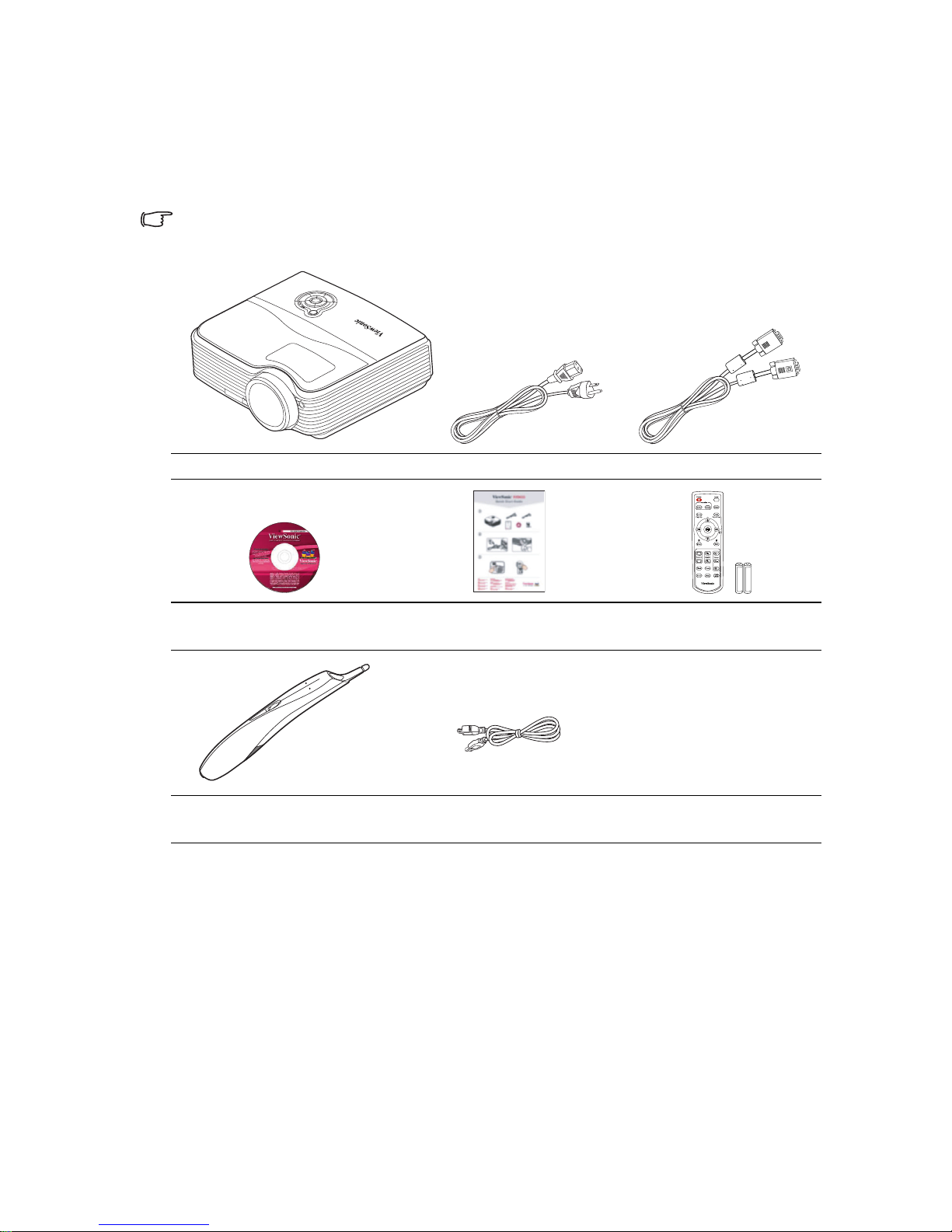
Shipping contents
Carefully unpack and verify that you have all of the items shown below. If any of these
items are missing, please contact your place of purchase.
Standard accessories
The supplied accessories will be suitable for your region, and may differ from those
illustrated.
Optional accessories
1. Ceiling mount
2. Replacement lamp
3. Soft carry case
Projector Power Cord VGA Cable
Multi-language user manual
DVD
Quick Start Guide Remote Control & Battery
PointBlank pen (PJD7383i/
PJD7583wi only)
USB Cable (PJD7383i/
PJD7583wi only)

Introduction 7
Projector exterior view
1. External control panel
(See "Projector" on page 8 for
details.)
2. Lamp cover
3. Vent (heated air exhaust)
4. Quick-release button
5. Lens cover
6. Front IR remote sensor
7. Focus ring
8. Projection lens
9. Kensington anti-theft lock slot
10. AC power cord inlet
11. Rear IR remote sensor
12. RJ45 LAN input port
13. Mini B USB port
14. Type A USB port
15. RS-232 control port
16. RGB signal output socket
17. RGB (PC)/Component video
(YPbPr/YCbCr) signal input
socket-1/2
18. Video input socket/
S-Video input socket
19. Audio signal input socket (L/R)
20. Audio signal input socket
Audio signal output socket
21. Microphone input socket
Connects a microphone with a 3.5
mm mini jack cable or wireless
module.
22. Security bar
Connects a commercially available
theft prevention cable.
23. 12V DC output terminal
Used to trigger external devices
such as an electric screen or light
control, etc. Consult your dealer for
how to connect these devices.
24. Rear adjuster foot
25. Quick-release foot
Warning
• THIS APPARATUS MUST BE EARTHED.
• When installing the unit, incorporate a readily accessible disconnect device in the fixed wiring,
or connect the power plug to an easily accessible socket-outlet near the unit. If a fault should
occur during operation of the unit, operate the disconnect device to switch the power supply
off, or disconnect the power plug.
Front/upper side
1
3
4
5
2
8
7
6
DC 12V OUT
Rear/lower side
25
24
24
23
16 1713
10
1911 12 18 20 2221
9
14
15
Introduction8
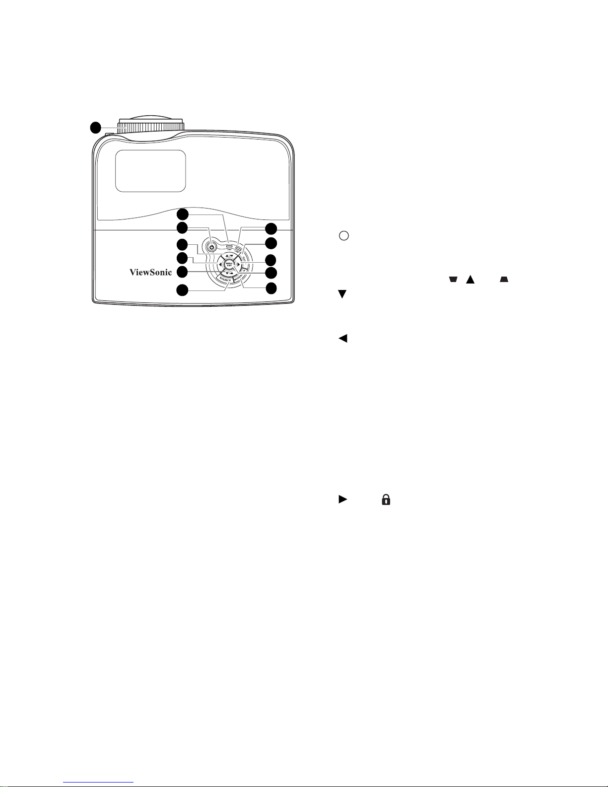
Controls and functions
Projector
1. Focus ring
Adjusts the focus of the projected image.
2. TEMPerature indicator light
Lights up red if the projector's
temperature becomes too high.
3. POWER indicator light
Lights up or flashes when the projector is
under operation.
POWER
Toggles the projector between standby
mode and on.
4. Keystone/Arrow keys ( / Up, /
Down)
Manually corrects distorted images
resulting from an angled projection.
5. Left/Blank
Hides the screen picture.
6. SOURCE
Displays the source selection bar.
7. LAMP indicator light
Indicates the status of the lamp. Lights up
or flashes when the lamp has developed a
problem.
8. AUTO
Automatically determines the best picture
timings for the displayed image.
9. Right/
Activates panel key lock.
When the On-Screen Display (OSD)
menu is activated, the #4, #5, and #9 keys
are used as directional arrows to select the
desired menu items and to make
adjustments.
10. MENU/EXIT
Turns on the On-Screen Display (OSD)
menu. Goes back to previous OSD menu,
exits and saves menu settings.
11. MODE/ENTER
Selects an available picture setup mode.
Enacts the selected On-Screen Display
(OSD) menu item.
1
8
9
7
10
11
6
2
3
5
4
4
I
I
Introduction 9
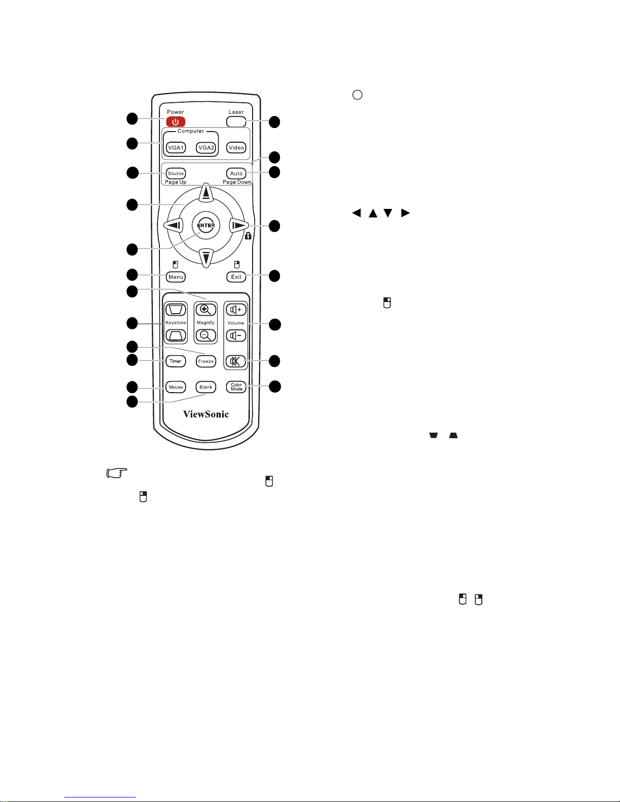
Remote control
1. POWER
Toggles the projector between standby
mode and on.
2. Source selection keys (VGA 1/VGA
2/Video)
Selects an input source for display.
3. Source
Displays the source selection bar.
4. / / /
Selects the desired menu items and
makes adjustments.
5. ENTER
Enacts the selected On-Screen Display
(OSD) menu item.
6. Menu/
Turns on the On-Screen Display
(OSD) menu.
Performs the same function as the left
mouse button when the mouse mode is
activated.
7. Magnify keys (+, -)
Magnifies or reduces the projected
picture size.
8. Keystone keys ( / )
Manually corrects distorted images
resulting from an angled projection.
9. Freeze
Freezes the projected image.
10. Timer
Displays the presentation timer
settings menu.
11. Mouse
Switches between the normal and
mouse modes.
Page Up, Page Down, , : active
after pressing Mouse. An icon appears
on the screen to indicate the activation
of the mouse mode.
12. Blank
Hides the screen picture.
To use the remote mouse control
keys (Page Up, Page Down, , and
), see "Using the remote mouse
control" on page 10 for details.
20
17
19
18
16
13
15
14
3
4
7
1
2
8
6
5
9
12
10
11
I
I
Introduction10
13. Laser
Emits visible laser pointer light for
presentation purposes.
14. Page Up/Page Down
Operates your display software program
(on a connected PC) which responds to
page up/down commands (like Microsoft
PowerPoint) when the mouse mode is
activated.
15. AUTO
Automatically determines the best picture
timings for the displayed image.
16. Right/
Activates panel key lock.
17. Exit/
Goes back to previous OSD menu, exits
and saves menu settings.
Performs the same function as the right
mouse button when the mouse mode is
activated.
18. Volume keys (+, -)
Magnifies or reduces the volume level.
19.
Toggles the projector audio between on and
off.
20. Color Mode
Selects an available picture setup mode.
Operating the Laser pointer
The Laser Pointer is a presentation aid for
professionals. It emits red colored light when you
press it and the indicator lights up red.
The laser beam is visible. It is necessary to press
and hold LASER for continuous output.
The laser pointer is not a toy. Parents should be
mindful of the dangers of laser energy and keep
this remote control out of the reach of children.
Do not look into the laser light window or
shine the laser light beam on yourself or
others. See the warning messages on the
back of the remote control prior to using it.
Using the remote mouse control
The capability of operating your computer with
the remote control gives you more flexibility
when delivering presentations.
1. Connect the projector to your PC or
notebook with a USB cable prior to using
the remote control in place of your
computer’s mouse.
2. Set the input signal to D-Sub / Comp. 1
or D-Sub / Comp. 2.
3. Press Mouse on the remote control to
switch from the normal mode to the
mouse mode. An icon appears on the
screen to indicate the activation of the
mouse mode.
4. Perform the desired mouse controls on
your remote control.
• To move the cursor on the screen,
press / / / .
• To left-click, press .
•To right-click, press .
• To drag-and-drop, press and hold
ENTER, press / / / to drag.
When it is where you want it, press
ENTER again.
• To operate your display software
program (on a connected PC) which
responds to page up/down commands
(like Microsoft PowerPoint), press
Page Up/Page Down.
• To return to the normal mode, press
Mouse again or other keys except for
the mouse related multi-function
keys.
Introduction 11
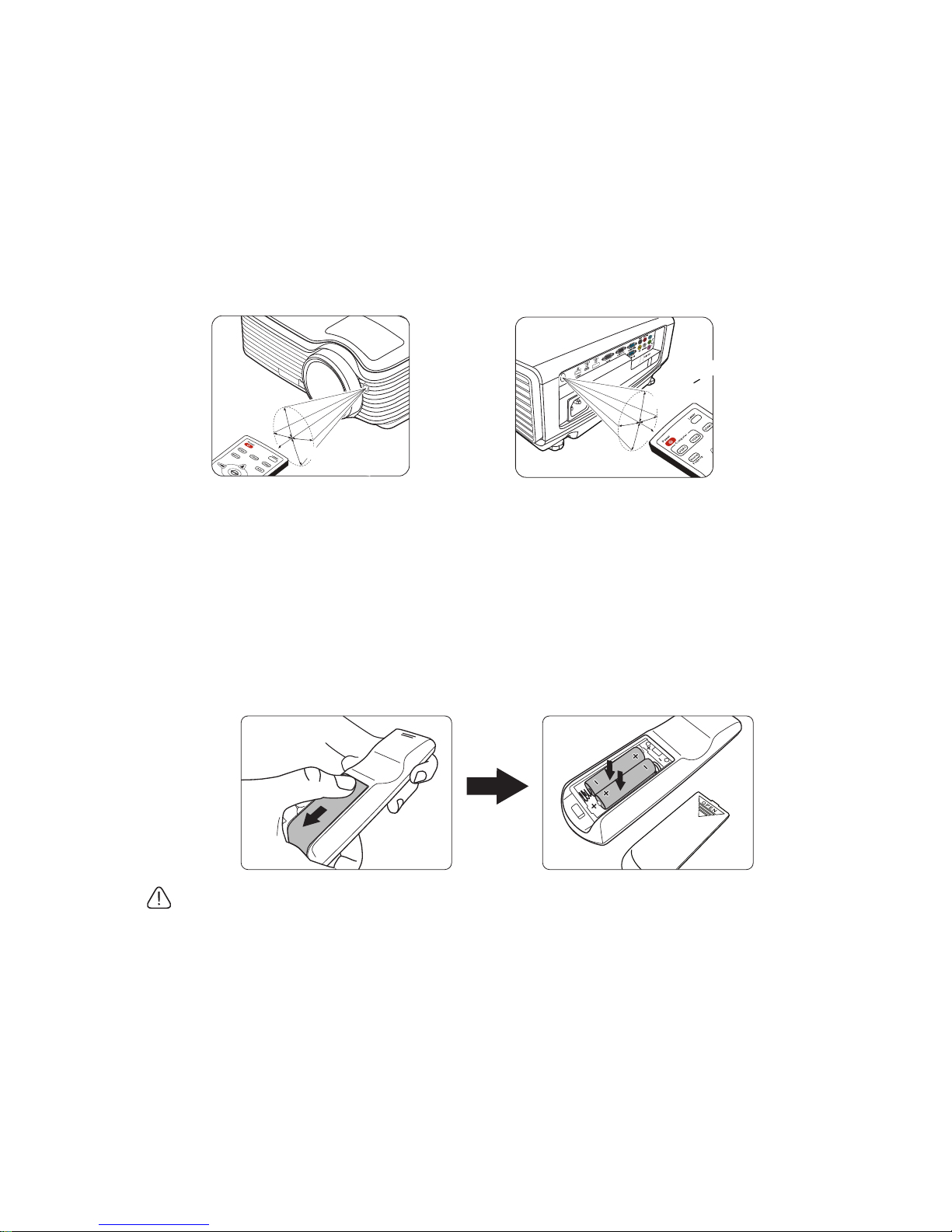
Remote control effective range
Infra-Red (IR) remote control sensors are located on the front and the back of the projector.
The remote control must be held at an angle within 30 degrees perpendicular to the
projector's IR remote control sensors to function correctly. The distance between the remote
control and the sensors should not exceed 8 meters (~ 26 feet).
Make sure that there are no obstacles between the remote control and the IR sensors on the
projector that might obstruct the infra-red beam.
Replacing the remote control batteries
1. To open the battery cover, turn the remote control over to view its back, push on the
finger grip on the cover and slide it in the direction of the arrow as illustrated. The
cover will slide off.
2. Remove any existing batteries (if necessary) and install two AAA batteries observing
the battery polarities as indicated in the base of the battery compartment. Positive (+)
goes to positive and negative (-) goes to negative.
3. Refit the cover by aligning it with the base and sliding it back down into position.
Stop when it clicks into place.
• Avoid leaving the remote control and batteries in an excessive heat or humid environment
like the kitchen, bathroom, sauna, sunroom or in a closed car.
• Replace only with the same or equivalent type recommended by the battery manufacturer.
• Dispose of the used batteries according to the manufacturer's instructions and local
environment regulations for your region.
• Never throw the batteries into a fire. There may be danger of an explosion.
• If the batteries are dead or if you will not be using the remote control for an extended
period of time, remove the batteries to avoid damage to the remote control from possible
battery leakage.
• Operating the projector from the
front
A
p
p
r
o
x
.
1
5°
A
p
p
r
o
x
.
+
1
5
°
• Operating the projector from the
rear
Positioning your projector12
Positioning your projector
Choosing a location
Your room layout or personal preference will dictate which installation location you select.
Take into consideration the size and position of your screen, the location of a suitable power
outlet, as well as the location and distance between the projector and the rest of your
equipment.
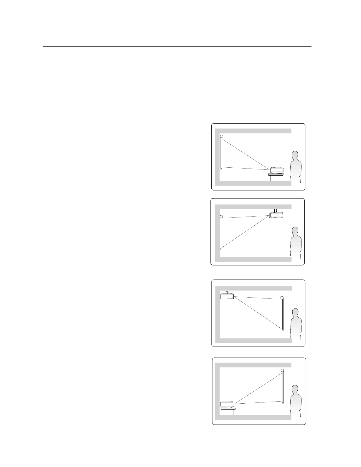
Your projector is designed to be installed in one of four possible installation locations:
1. Front Table
Select this location with the projector placed near
the floor in front of the screen. This is the most
common way to position the projector for quick
setup and portability.
2. Front Ceiling
Select this location with the projector suspended
upside-down from the ceiling in front of the
screen.
Purchase the projector ceiling mount kit from your
dealer to mount your projector on the ceiling.
Set Front Ceiling in the SYSTEM SETUP:
Basic > Projector Position menu after you turn
the projector on.
3. Rear Ceiling
Select this location with the projector suspended
upside-down from the ceiling behind the screen.
Note that a special rear projection screen and the
projector ceiling mounting kit are required for this
installation location.
Set Rear Ceiling in the SYSTEM SETUP: Basic
> Projector Position menu after you turn the
projector on.
4. Rear Table
Select this location with the projector placed near
the floor behind the screen.
Note that a special rear projection screen is
required.
Set Rear Table in the SYSTEM SETUP: Basic >
Projector Position menu after you turn the
projector on.
Positioning your projector 13
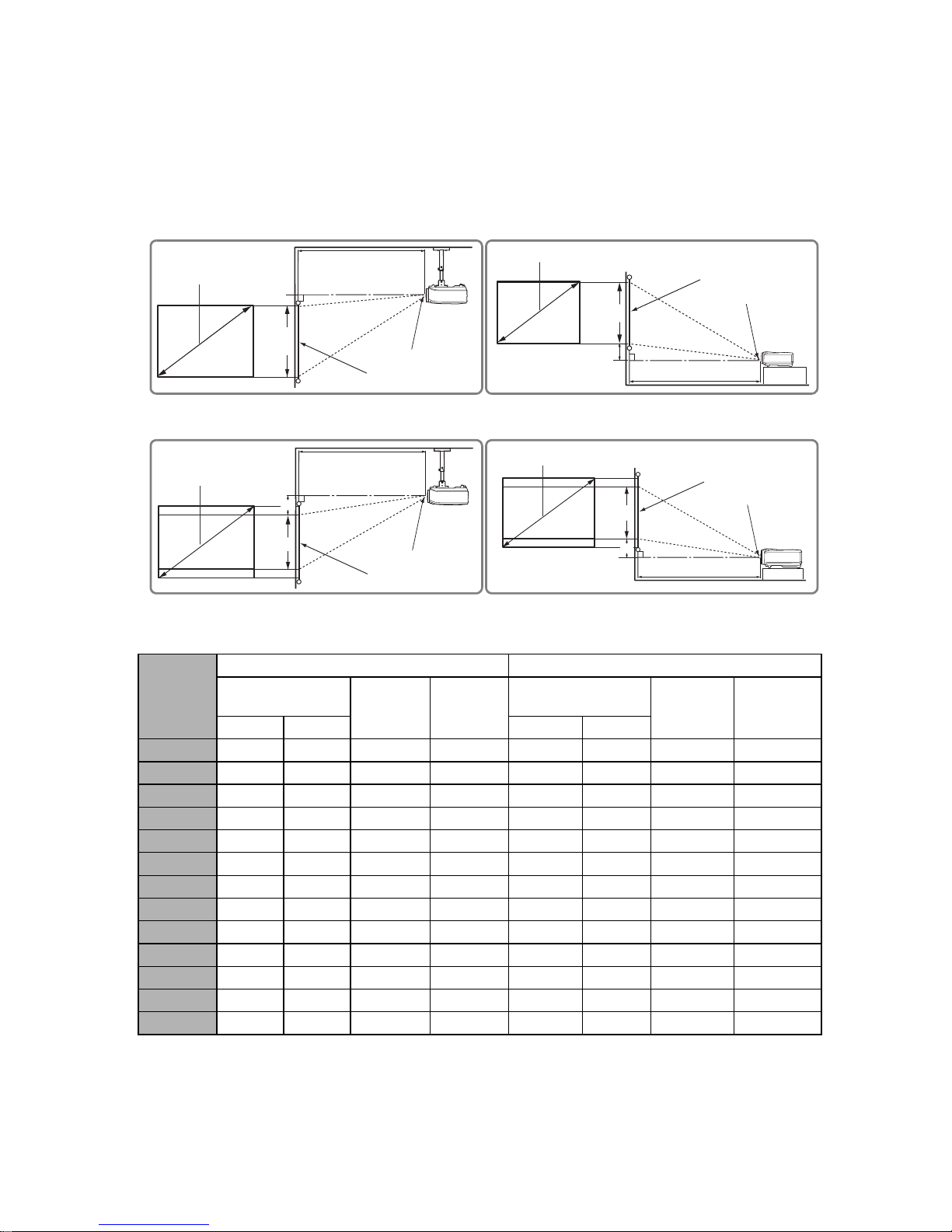
Projection dimensions
Refer to "Dimensions" on page 77 for the center of lens dimensions of this projector before
calculating the appropriate position.
PJD7383/PJD7383i
(a) Screen
Size
[inch (m)]
4:3 image 16:9 image
(b) Projection
distance [m (inch)]
(c) Image
height
[cm (inch)]
(d) Vertical
offset
[cm (inch)]
(b) Projection
distance [m (inch)]
(c) Image
height
[cm (inch)
(d) Vertical
offset
[cm (inch)]
min. max. min. max.
30 (0.8) 0.4 (15) 0.4 (15) 46 (18) 7 (2.7) 0.4 (15) 0.4 (15) 34 (14) 12.6 (5.0)
40 (1.0) 0.5 (19) 0.5 (19) 61 (24) 9 (3.6) 0.5 (19) 0.5 (19) 46 (18) 16.8 (6.6)
50 (1.3) 0.6 (24) 0.6 (24) 76 (30) 11 (4.5) 0.6 (24) 0.6 (24) 57 (23) 21.0 (8.3)
60 (1.5) 0.7 (29) 0.7 (29) 91 (36) 14 (5.4) 0.7 (29) 0.7 (29) 69 (27) 25.1 (9.9)
70 (1.8) 0.9 (34) 0.9 (34) 107 (42) 16 (6.3) 0.9 (34) 0.9 (34) 80 (32) 29.3 (11.6)
80 (2.0) 1.0 (39) 1.0 (39) 122 (48) 18 (7.2) 1.0 (39) 1.0 (39) 91 (36) 33.5 (13.2)
90 (2.3) 1.1 (44) 1.1 (44) 137 (54) 21 (8.1) 1.1 (44) 1.1 (44) 103 (41) 37.7 (14.9)
100 (2.5) 1.2 (49) 1.2 (49) 152 (60) 23 (9.0) 1.2 (49) 1.2 (49) 114 (45) 41.9 (16.5)
120 (3.0) 1.5 (58) 1.5 (58) 183 (72) 27 (10.8) 1.5 (58) 1.5 (58) 137 (54) 50.3 (19.8)
150 (3.8) 1.9 (73) 1.9 (73) 229 (90) 34 (13.5) 1.9 (73) 1.9 (73) 171 (68) 62.9 (24.8)
200 (5.1) 2.5 (97) 2.5 (97) 305 (120) 46 (18.0) 2.5 (97) 2.5 (97) 229 (90) 83.8 (33.0)
250 (6.4) 3.1 (122) 3.1 (122) 381 (150) 57 (22.5) 3.1 (122) 3.1 (122) 286 (113) 104.8 (41.3)
300 (7.6) 3.7 (146) 3.7 (146) 457 (180) 69 (27.0) 3.7 (146) 3.7 (146) 343 (135) 125.7 (49.5)
(a)
(c)
(b)
(e)
(f)
(d)
(a)
(d)
(b)
(e)
(f)
(c)
(a)
(d)
(c)
(b)
(e)
(f)
(a)
(c)
(b)
(e)
(f)
(d)
(f): Center of lens(e): Screen
• 4:3 image on a 4:3 screen
• 16:9 image on a 4:3 screen
Positioning your projector14
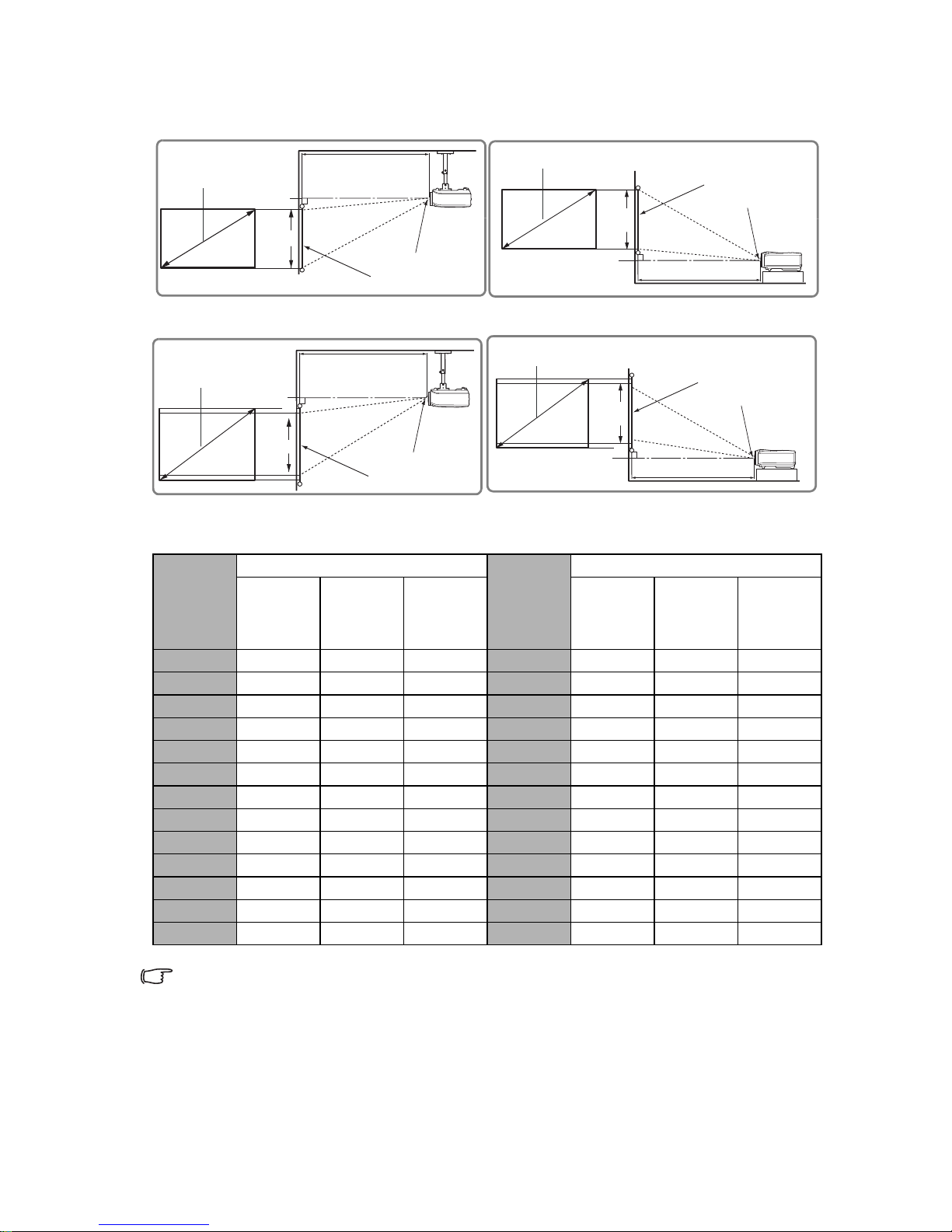
PJD7583w/PJD7583wi
There is 3% tolerance among these numbers due to optical component variations. It is
recommended that if you intend to permanently install the projector, you should physically
test the projection size and distance using the actual projector in situ before you permanently
install it, so as to make allowance for this projector's optical characteristics. This will help you
determine the exact mounting position so that it best suits your installation location.
(a) 16:10
Screen Size
[inch (m)]
16:10 image
(a) 4:3
Screen Size
[inch (m)]
16:10 image
(b)
Projection
distance [m
(inch)]
(c) Image
height
[cm (inch)]
(d) Vertical
offset
[cm (inch)]
(b)
Projection
distance [m
(inch)]
(c) Image
height
[cm (inch)
(d) Vertical
offset
[cm (inch)]
30 (0.8) 0.32 (12) 40 (16) 2 (0.8) 30 (0.8) 0.3 (12) 38 (15) 3.8 (1.5)
40 (1.0) 0.42 (17) 54 (21) 3 (1.1) 40 (1.0) 0.4 (16) 51 (20) 5.1 (2.0)
50 (1.3) 0.53 (21) 67 (26) 3 (1.3) 50 (1.3) 0.5 (20) 64 (25) 6.4 (2.5)
60 (1.5) 0.63 (25) 81 (32) 4 (1.6) 60 (1.5) 0.6 (23) 76 (30) 7.6 (3.0)
70 (1.8) 0.74 (29) 94 (37) 5 (1.9) 70 (1.8) 0.70 (27) 89 (35) 8.9 (3.5)
80 (2.0) 0.84 (33) 108 (42) 5 (2.1) 80 (2.0) 0.79 (31) 102 (40) 10.2 (4.0)
90 (2.3) 0.95 (37) 121 (48) 6 (2.4) 90 (2.3) 0.89 (35) 114 (45) 11.4 (4.5)
100 (2.5) 1.05 (41) 135 (53) 7 (2.6) 100 (2.5) 0.99 (39) 127 (50) 12.7 (5.0)
120 (3.0) 1.26 (50) 162 (64) 8 (3.2) 120 (3.0) 1.19 (47) 152 (60) 15.2 (6.0)
150 (3.8) 1.58 (62) 202 (79) 10 (4.0) 150 (3.8) 1.49 (59) 191 (75) 19.1 (7.5)
200 (5.1) 2.11 (83) 269 (106) 13 (5.3) 200 (5.1) 1.99 (78) 254 (100) 25.4 (10.0)
250 (6.4) 2.63 (104) 337 (132) 17 (6.6) 250 (6.4) 2.48 (98) 318 (125) 31.8 (12.5)
300 (7.6) 3.16 (124) 404 (159) 20 (7.9) 300 (7.6) 2.98 (117) 381 (150) 38.1 (15.0)
(a)
(d)
(c)
(b)
(e)
(f)
(a)
(c)
(b)
(e)
(f)
(d)
(a)
(c)
(b)
(e)
(f)
(d)
(a)
(c)
(b)
(e)
(f)
(d)
(f): Center of lens(e): Screen
• 16:10 image on a 4:3 screen
• 16:10 image on a 16:10 screen
Connection 15
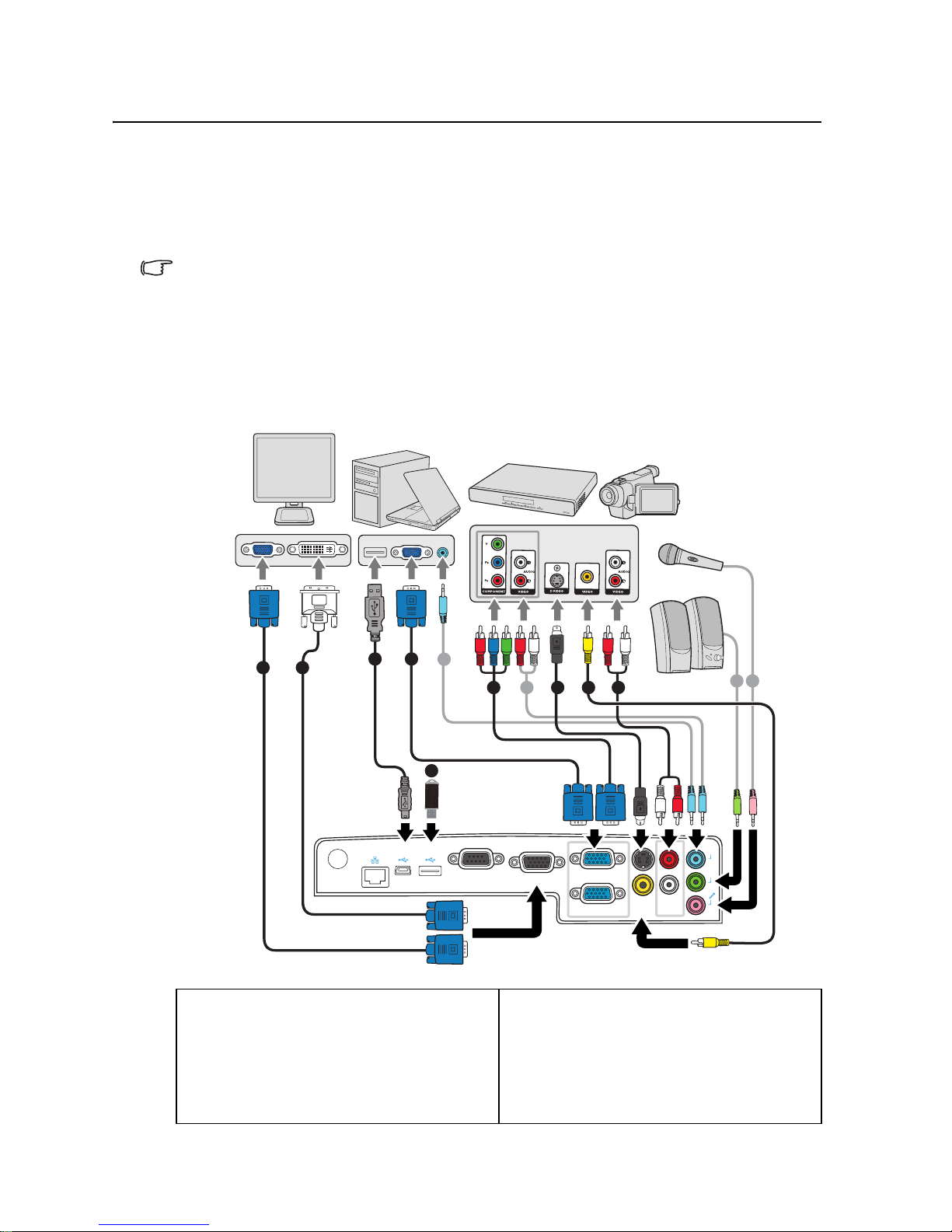
Connection
When connecting a signal source to the projector, be sure to:
1. Turn all equipment off before making any connections.
2. Use the correct signal cables for each source.
3. Ensure the cables are firmly inserted.
• In the connections shown below, some cables may not be included with the projector (see
"Shipping contents" on page 6). They are commercially available from electronics stores.
• The connection illustrations below are for reference only. The rear connecting jacks
available on the projector vary with each projector model.
• For detailed connection methods, see pages 16-18.
1. VGA cable
2. VGA to DVI-A cable
3. USB cable
4. Component Video to VGA (D-Sub)
adapter cable
5. S-Video cable
6. Video cable
7. Audio L/R cable
8. Audio cable
9. Microphone 3.5 mini jack cable
10. USB flash drive/USB wireless dongle
TYPE B
USB
LAN
TYPE A
USB
RS 232
MONITOR OUT
COMPUTER IN1
COMPUTER IN2
S-VIDEO
VIDEO
AUDIO IN2 (R)
AUDIO IN2 (L)
AUDIO
IN1
AUDIO
OUT
MIC
5 7
8
8
8 9
4
1
2
1
6
3
10
Notebook or
desktop computer
Speakers
or
A/V device
Monitor
(DVI)(VGA)
Microphone

Connection16
Connecting a computer or monitor
Connecting a computer
The projector provides two VGA input sockets that allow you to connect them to both
IBM® compatibles and Macintosh® computers. A Mac adapter is needed if you are
connecting legacy version Macintosh computers.
To connect the projector to a notebook or desktop computer:
• Using a VGA cable
1. Take the supplied VGA cable and connect one end to the D-Sub output socket of the
computer.
2. Connect the other end of the VGA cable to the COMPUTER IN 1 or COMPUTER
IN 2 signal input socket on the projector.
• Using a USB cable
1. Take a USB mini-B type to USB A type cable and connect one end to the A type jack
of the computer.
2. Connect the other end of the cable to the mini-B jack on the projector.
3. Press Source to select USB B as the input signal.
Many notebooks do not turn on their external video ports when connected to a projector.
Usually a key combo like FN + F3 or CRT/LCD key turns the external display on/off. Locate a
function key labeled CRT/LCD or a function key with a monitor symbol on the notebook. Press
FN and the labeled function key simultaneously. Refer to your notebook's documentation to
find your notebook's key combination.
Connecting a monitor
If you want to view your presentation close-up on a monitor as well as on the screen, you
can connect the MONITOR OUT signal output socket on the projector to an external
monitor with a VGA cable following the instructions below:
To connect the projector to a monitor:
1. Connect the projector to a computer as described in "Connecting a computer" on page
16.
2. Take a suitable VGA cable (only one supplied) and connect one end of the cable to the
D-Sub input socket of the video monitor.
Or if your monitor is equipped with a DVI input socket, take a VGA to DVI-A cable
and connect the DVI end of the cable to the DVI input socket of the video monitor.
3. Connect the other end of the cable to the MONITOR OUT socket on the projector.
• The MONITOR OUT output only works when COMPUTER IN 1 or COMPUTER IN 2 is made
to the projector.
• To use this connection method when the projector is in standby mode, turn on the Active
VGA Out function under the SYSTEM SETUP: Advanced > Standby Settings menu.

Connection 17
Connecting Video source devices
You can connect your projector to various Video source devices that provide any one of the
following output sockets:
• Component Video
•S-Video
• Video (composite)
You need only connect the projector to a Video source device using just one of the above
connecting methods, however each provides a different level of video quality. The method
you choose will most likely depend upon the availability of matching terminals on both the
projector and the Video source device as described below:
Best video quality
The best available video connection method is Component Video (not to be confused with
composite Video). Digital TV tuner and DVD players output Component Video natively, so
if available on your devices, this should be your connection method of choice in preference
to (composite) Video.
See "Connecting a Component Video source device" on page 18 for how to connect the
projector to a component video device.
Better video quality
The S-Video method provides a better quality analog video than standard composite Video.
If you have both composite Video and S-Video output terminals on your Video source
device, you should elect to use the S-Video option.
See "Connecting an S-Video source device" on page 18 for how to connect the projector to
an S-Video device.
Least video quality
Composite Video is an analog video and will result in a perfectly acceptable, but less than
optimal result from your projector, being the least video quality of the available methods
described here.
See "Connecting a composite Video source device" on page 19 for how to connect the
projector to a composite Video device.

Connection18
Connecting a Component Video source device
Examine your Video source device to determine if it has a set of unused Component Video
output sockets available:
• If so, you can continue with this procedure.
• If not, you will need to reassess which method you can use to connect to the device.
To connect the projector to a Component Video source device:
1. Take a Component Video to VGA (D-Sub) adaptor cable and connect the end with 3
RCA type connectors to the Component Video output sockets of the Video source
device. Match the color of the plugs to the color of the sockets; green to green, blue to
blue, and red to red.
2. Connect the other end of the Component Video to VGA (D-Sub) adaptor cable (with a
D-Sub type connector) to the COMPUTER IN 1 or COMPUTER IN 2 socket on the
projector.
• If the selected video image is not displayed after the projector is turned on and the correct
video source has been selected, check that the Video source device is turned on and
operating correctly. Also check that the signal cables have been connected correctly.
•
Connecting an S-Video source device
Examine your Video source device to determine if it has an unused S-Video output socket
available:
• If so, you can continue with this procedure.
• If not, you will need to reassess which method you can use to connect to the device.
To connect the projector to an S-Video source device:
1. Take an S-Video cable and connect one end to the S-Video output socket of the Video
source device.
2. Connect the other end of the S-Video cable to the S-VIDEO socket on the projector.
• If the selected video image is not displayed after the projector is turned on and the correct
video source has been selected, check that the Video source device is turned on and
operating correctly. Also check that the signal cables have been connected correctly.
• If you have already made a Component Video connection between the projector and this
S-Video source device using Component Video connections, you need not connect to this
device using an S-Video connection as this makes an unnecessary second connection of
poorer picture quality. See "Connecting Video source devices" on page 17 for details.
VGA-Component adapter
(ViewSonic P/N: CB-00008906)

Connection 19
Connecting a composite Video source device
Examine your Video source device to determine if it has a set of unused composite Video
output sockets available:
• If so, you can continue with this procedure.
• If not, you will need to reassess which method you can use to connect to the device.
To connect the projector to a composite Video source device:
1. Take a Video cable and connect one end to the composite Video output socket of the
Video source device.
2. Connect the other end of the Video cable to the VIDEO socket on the projector.
• If the selected video image is not displayed after the projector is turned on and the correct
video source has been selected, check that the Video source device is turned on and
operating correctly. Also check that the signal cables have been connected correctly.
• You need only connect to this device using a composite Video connection if Component
Video and S-Video inputs are unavailable for use. See "Connecting Video source devices"
on page 17 for details.
Playing sound through the projector
You can make use of the projector (mixed mono) speaker in your presentations, and also
connect separate amplified speakers to the AUDIO OUT socket of the projector.
If you have a separate sound system, you will most likely want to connect the audio output
of your Video source device to that sound system, instead of to the mono audio projector.
You can also use a microphone to output the sound through the projector speaker.
Once connected, the audio can be controlled by the projector On-Screen Display (OSD)
menus. See "Audio Settings" on page 66 for details.
The table below describes the connection methods for different devices, and where the
sound is from.
About the microphone input
• If you wish to use a microphone, connect a 3.5 mini jack cable microphone to the
projector.
• You can use a wireless microphone as long as a wireless module is attached to the
projector’s microphone input jack and it works well with the associated devices. To
Device
PC/Component Video Video/S-Video Microphone
Audio input port
AUDIO IN 1 AUDIO IN 2 (L/R)
MIC
The projector can
play the sound
from...
AUDIO IN 1/MIC AUDIO IN 2 (L/R)/MIC
•MIC
• AUDIO IN 1/MIC
• AUDIO IN 2 (L/R)/
MIC
Audio output port
AUDIO OUT AUDIO OUT AUDIO OUT
The selected input signal determines which sound will be played by the projector speaker,
and which sound will be output from the projector when AUDIO OUT is connected. If you
select a PC signal, the projector can play the sound received from AUDIO IN 1/MIC.

Connection20
ensure a quality use of the wireless microphone, it is recommended that your
microphone conforms to the specifications listed in the table below.
• There are two ways to adjust microphone volumes.
• Directly set microphone volume levels in the SYSTEM SETUP: Advanced > Audio
Settings > Microphone Volume menu.
• Set projector volume levels in the SYSTEM SETUP: Advanced > Audio Settings >
Volume menu, or press Volume keys (+, -) on the remote control. (The projector
volume setting will affect the microphone volume.)
• To make the microphone input available when the projector is in standby mode, turn on
the SYSTEM SETUP: Basic > Standby Settings > Microphone menu.
• If the microphone is not working, check the volume setting and cable connection.
• You might get feedback noise from the microphone when you are too close to the
speaker of the projector. Move the microphone away from the speaker of the projector.
The greater volume you require, the greater distance you need to be away from the
speaker to prevent the noise.
Signal Parameter Min Type Max
Microphone
Transducer Principle Dynamic
Impedance 300 1K ohm
Frequency response 600 16k Hz
Operation 21
Operation
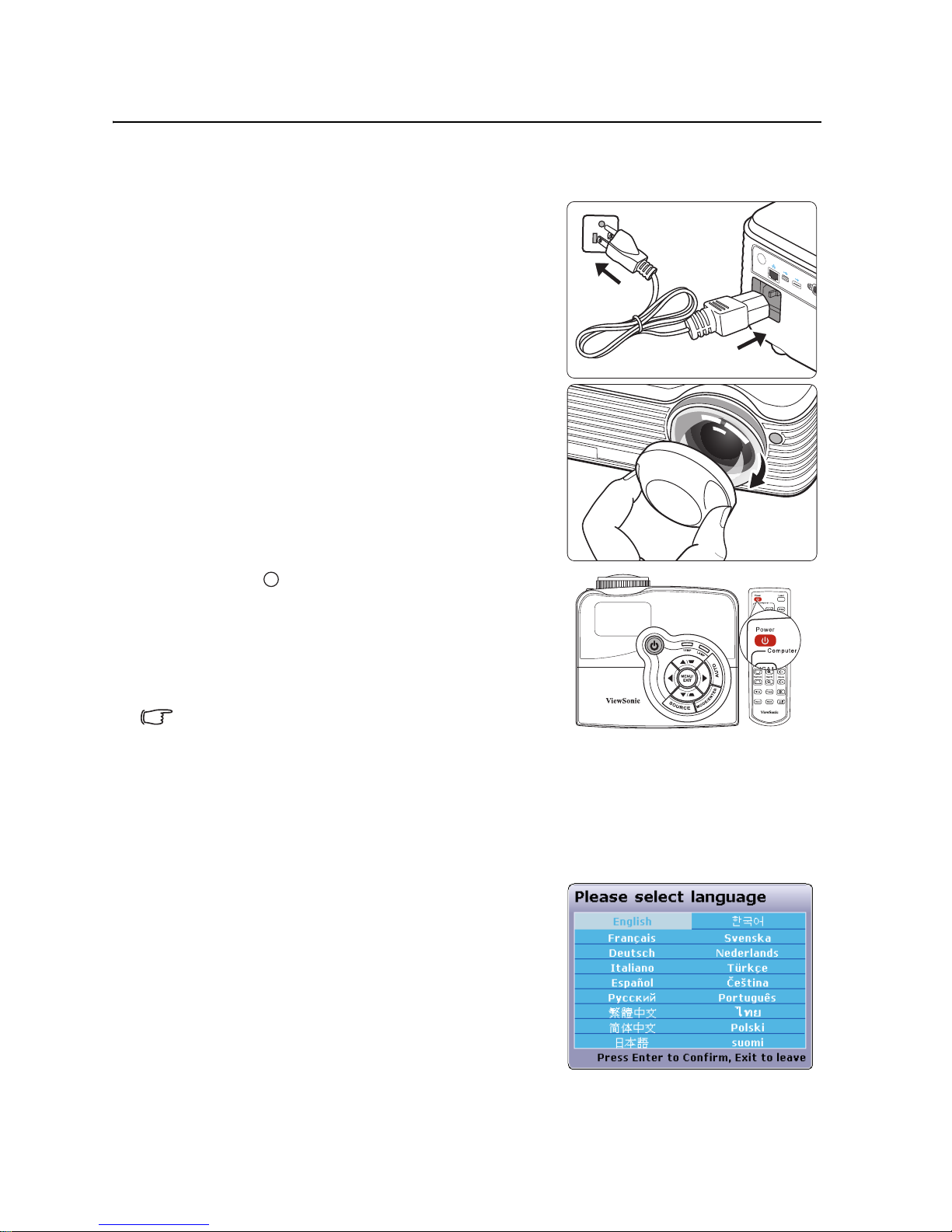
Starting up the projector
1. Plug the power cord into the projector and into a
wall socket. Turn on the wall socket switch
(where fitted). Check that the POWER
indicator light on the projector flashes blue
after power has been applied.
2. Remove the lens cap. If it is closed, it could
become deformed due to the heat produced by
the projection lamp.
3. Press POWER on the projector or remote
control to start the projector. The POWER
indicator light stays blue when the projector is
on.
(If necessary) Rotate the focus ring to adjust the
image clearness.
• If the projector is still hot from previous activity, it
will run the cooling fan for approximately 90
seconds before energizing the lamp.
• To maintain the lamp life, once you turn the
projector on, wait at least 5 minutes before turning
it off.
4. If the projector is activated for the first time,
select your OSD language following the onscreen instructions.
5. Switch all of the connected equipment on.
LAN
R
S
TYPE
A
TYPE
B
USB
USB
I
I

Operation22
6. The projector will start to search for input signals. The current input signal being
scanned appears in the upper left corner of the screen. If the projector doesn't detect a
valid signal, the message 'No Signal' will continue to be displayed until an input
signal is found.
You can also press SOURCE on the projector or remote control to select your desired
input signal. See "Switching input signal" on page 26 for details.
If the frequency/resolution of the input signal exceeds the projector's operating range, you will
see the message 'Out of Range' displayed on a blank screen. Please change to an input signal
which is compatible with the projector's resolution or set the input signal to a lower setting.
See "Timing chart" on page 77 for details.
Operation 23
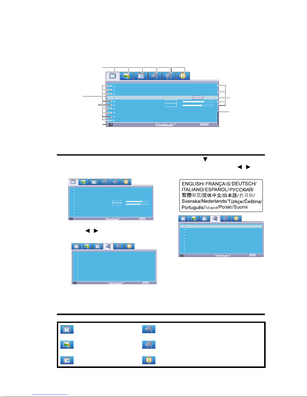
Using the menus
The projector is equipped with On-Screen Display (OSD) menus for making various
adjustments and settings.
Below is the overview of the OSD menu.
To use the OSD menus, please set them to your familiar language first.
1. Press MENU/EXIT on the projector or
Menu on the remote control to turn the
OSD menu on.
3. Press to highlight
Language and press / to
select a preferred language.
4. Press MENU/EXIT twice* on
the projector or Exit on the
remote control to leave and
save the settings.
*The first press leads you back
to the main menu and the
second press closes the OSD
menu.
2. Use / to highlight the SYSTEM
SETUP: Basic menu.
: DISPLAY
: PICTURE
: SOURCE
: SYSTEM SETUP: Basic
: SYSTEM SETUP: Advanced
: INFORMATION
Current input
signal
Main menu icon
Sub-menu
Highlight
Go to the
previous page
or to exit.
Status
Screen Color
Aspect Ratio
Phase
H. Size
Zoom
Off
Auto
16
0
MENU Exit
Analog RGB
ENTER
Keystone
Position
3D Sync On
Disable3D Sync Invert
Color Management
Screen Color
Aspect Ratio
Position
Phase
H. Size
Zoom
Off
Auto
MENU
Exit
Keystone
16
0
Analog RGB
3D Sync On
3D Sync Invert
Color Management
Disable
Projector Position
Auto Power Off
Blank Timer
Panel Key Lock
Splash Screen
Analog RGB
MENU Exit
Front Table
Disable
Disable
Off
ViewSonic
English
Language
Screen Capture
Message On
LAN Control Settings
Standby Settings
Projector Position
Auto Power Off
Blank Timer
Panel Key Lock
Splash Screen
Analog RGB
MENU Exit
Front Table
Disable
Disable
Off
ViewSonic
EnglishLanguage
Screen Capture
Message On
LAN Control Settings
Standby Settings

Operation24
Utilizing the password function
For security purposes and to help prevent unauthorized use, the projector includes an option
for setting up password security. The password can be set through the On-Screen Display
(OSD) menu. For details of the OSD menu operation, please refer to "Using the menus" on
page 23.
You will be inconvenienced if you activate the password functionality and subsequently forget
the password. Print this user manual (if necessary) and write the password you used in this
manual, and keep it in a safe place for later use.
Setting a password
1. Open the OSD menu and go to the SYSTEM SETUP: Advanced > Security
Settings menu. Press MODE/ENTER on the projector or ENTER on the remote
control. The Security Settings page is displayed.
2. Highlight Power On Lock and select On by pressing / .
3. As pictured to the right, the four arrow keys ( ,
, , ) respectively represent 4 digits (1, 2,
3, 4). According to the password you desire to
set, press the arrow keys to enter six digits for the
password.
4. Confirm the new password by re-entering the
new password.
Once the password is set, the OSD menu returns to the Security Settings page.
5. To leave the OSD menu, press MENU/EXIT on the projector or Exit on the remote
control.
• Once a password has been set, the projector cannot be used unless the correct password
is entered every time the projector is started.
• The digits being input will be displayed as asterisks on-screen. Write your selected
password down here in this user manual in advance or right after the password is entered
so that it is available to you should you ever forget it.
Password: __ __ __ __ __ __
Keep this user manual in a safe place.
If you forget the password
If the password function is activated, you will be asked
to enter the six-digit password every time you turn on
the projector. If you enter the wrong password, the
password error message as pictured to the right is
displayed lasting for three seconds, and the message
'INPUT PASSWORD' follows. You can retry by
entering another six-digit password, or if you did not
record the password in this user manual, and you absolutely do not remember it, you can use
the password recall procedure. See "Entering the password recall procedure" on page 25 for
details.
If you enter an incorrect password 5 times in succession, the projector will automatically
shut down in a short time.
INPUT NEW PASSWORD
BackMENU
Password Error
Please try again.

Operation 25
Entering the password recall procedure
1. Press and hold AUTO on the projector or remote
control for 3 seconds. The projector will display
a coded number on the screen.
2. Write down the number and turn off your
projector.
3. Seek help from the local service center to decode
the number. You may be required to provide
proof of purchase documentation to verify that
you are an authorized user of the projector.
Changing the password
1. Open the OSD menu and go to the SYSTEM SETUP: Advanced > Security
Settings > Change Password menu.
2. Press MODE/ENTER on the projector or ENTER on the remote control. The
message 'INPUT CURRENT PASSWORD' is displayed.
3. Enter the old password.
• If the password is correct, another message 'INPUT NEW PASSWORD' is
displayed.
• If the password is incorrect, the password error message is displayed lasting for
three seconds, and the message 'INPUT CURRENT PASSWORD' is
displayed for your retry. You can press MENU/EXIT on the projector or Exit
on the remote control to cancel the change or try another password.
4. Enter a new password.
5. Confirm the new password by re-entering the new password.
6. You have successfully assigned a new password to the projector. Remember to enter
the new password next time the projector is started.
7. To leave the OSD menu, press MENU/EXIT on the projector or Exit on the remote
control.
The digits being input will be displayed as asterisks on-screen. Write your selected password
down here in this user manual in advance or right after the password is entered so that it is
available to you should you ever forget it.
Password: __ __ __ __ __ __
Keep this user manual in a safe place.
Disabling the password function
To disable password protection, go back to the SYSTEM SETUP: Advanced > Security
Settings > Power On Lock menu after opening the OSD menu system. Select Off by
pressing / . The message 'INPUT PASSWORD' is displayed. Enter the current
password.
• If the password is correct, the OSD menu returns to the Security Settings page
with 'Off' shown in the row of Power On Lock. You will not have to enter the
password next time you turn on the projector.
• If the password is incorrect, the password error message is displayed lasting for
three seconds, and the message 'INPUT PASSWORD' is displayed for your
Please write down the recall code,
and contact ViewSonic
Customer Center.
Recall code:
0 2 1 2
RECALL PASSWORD
Exit
MENU
 Loading...