

ViewSonic VS11856 Pro8100-1, VS11856 Service Manual

ViewSonic Pro8100-1
Model No. VS11856
Multimedia LCD Projector
(PRO8100-1_SM Rev. 1b Dec. 2008)
ViewSonic 381 Brea Canyon Road, Walnut, California 91789 USA - (800) 888-8583
Service Manual
i
ViewSonic Corporation Confidential - Do Not Copy PRO8100-1
Copyright
Copyright © 2008 by ViewSonic Corporation. All rights reserved. No part of this publication
may be reproduced, transmitted, transcribed, stored in a retrieval system, or translated into any
language or computer language, in any form or by any means, electronic, mechanical, magnetic,
optical, chemical, manual or otherwise, without the prior written permission of ViewSonic
Corporation.
Disclaimer
ViewSonic makes no representations or warranties, either expressed or implied, with respect to
the contents hereof and specifically disclaims any warranty of merchantability or fitness for any
particular purpose. Further, ViewSonic reserves the right to revise this publication and to make
changes from time to time in the contents hereof without obligation of ViewSonic to notify any
person of such revision or changes.
Trademarks
Optiquest is a registered trademark of ViewSonic Corporation.
ViewSonic is a registered trademark of ViewSonic Corporation.
All other trademarks used within this document are the property of their respective owners.
Product disposal at end of product life
The lamp in this product contains mercury. Please dis pose of in accordance with local, state or
federal laws.
Revision History
Revision SM Editing Date ECR Number Description of Changes Editor
1a 1/15/2008 Initial Release Jamie Chang
1b 12/15/2008 VS-E080372 RSPL update Sophia Kao
ii
ViewSonic Corporation Confidential - Do Not Copy PRO8100-1
TABLE OF CONTENTS
1. Specifications 1
2. Front Panel Function Control Description 4
3. Circuit Description 6
4. Adjustment Procedure 15
5. Troubleshooting 54
6. Block Diagram 67
7. Schematic Diagrams 68
8. PCB Layout Diagrams 100
9. Exploded Diagrams 102
10. Recommended Spare Parts List 105
11. Appendix 110
1
ViewSonic Corporation Confidential - Do Not Copy PRO8100-1
1. Specifications
Technical Specification
Pro8100
Display Type 3 x 0.74-inch LCD projector
Resolution(Pixels) 1920 x 1080 (1.07 Billion Colors)
F # F = 1.83 – 2.36
Focal Length f = 23.5 to 37.6 mm
Focus / Zoom Motorized / Motorized 1.6x
Lens shift Vertical: ±75%
Horizontal: ±5%
Projection distance 40” – 300”
Computer input Analog RGB, D-sub 15 pin
Video input HDMIx2, Component video (YCbCr/YPbPr)x2, Composite
videox1, S-Videox1.
Other terminals RS-232, USB, DC 5V, DC 12V trigger
Computer Compatibility Please refer to timing table above.
Video Compatibility NTSC, PAL, SECAM, 1080i/p, 720p, 576i/p, 480i/p
Scanning Frequency
Horizontal Frequency
Vertical Frequency
15-100kHz
50 - 90Hz
Operating temperature
0°C to +40°C / 32°F to +104°F
Rated AC 100-240V~50-60Hz 2.5A
Dimension (W x H x D) 537 x 170 x 389mm
Weight
19.4±0.44 lbs (8.8±0.2kg)
Note: Designs and specifications are subject to change without prior notice

2
ViewSonic Corporation Confidential - Do Not Copy PRO8100-1
Lamp Specification
Product Type: Short arc mercury lamp with reflector.
USHIO’s Type: NSH160HO
USHIO’s Lamp Driver Type: PHG201G20UU
Initial Characteristics
Initial Burner Characteristics;
Wattage(W) Lamp Voltage(V) Lamp Current(A) Efficiency((lm/W) Arc Gap(mm)
DC160 70 2.3 57 1.05
Lamp Life
The lamp life represents the average number of hours when the illuminance drops to less than
50% of its initial value under the following conditions with specific optical system. The nominal
lamp life at 160W is (2000) hours. USHIO will continue its lamp life measurement.
♦ The lamp must be operated under the proper temperature condition.
♦ The lamp must be operated on the USHIO’s lamp driver.
♦ On/Off cycle: 2 hours on, 15 minutes off.
♦ Ambient temperature should be room temperature (about 25℃)
♦ Illuminance should be measured on the specific optical system.

3
ViewSonic Corporation Confidential - Do Not Copy PRO8100-1
Attention for handling
♦ Do not touch the lamp until it has cooled completely, because the lamp is very hot
during operation and immediately after turned off.
♦ The lamp has to be fixed firmly to the base or socket.
♦ Turn off the power supply during maintenance.
♦ Do not hold the lamp except outer surface of the reflector.
♦ Wear protective gloves and eyeglasses when handling the lamp.
♦ Any unusual shock or vibration to the lamp should be avoided.
♦ The lamp contains the mercury. Its breakage might cause mercury to flow out of the
reflector. Please manage provision at the customer’s product.
♦ Do not pull the lead wire and plug by more than 24.5N.
♦ Please be careful of handling the lamp because it is made of glass.
♦ Please notice for keeping or handling the lamp, because there is a projection of this
lamp with reflector ahead.
♦ Do not touch the bulb and the mirror area of the reflector.
Attention for use
♦ Do not close or cover the lamp with any flammable stuff.
♦ During operation, the lamp is under extremely high pressure. Please manage
provision at the customer’s product to prevent fragments of bulb and mercury from
flowing out of it. If the lamp bursts in case of an emergency, the sound will be occurred.
♦ Lamp operation should be with the specified lamp driver and the system ONLY.
♦ Do not look at the lamp directly during operations.
♦ Do not expose your skin directly. We recommend to you to put on something for
protection for your skin. For example, long sleeve shirt, gloves, glassed and so on.
♦ Do not modify the lamp and never use a lamp that has been modified.
♦ Any unusual shock or vibration to the lamp should be avoided during operation.
♦ Do not use any broken lamps.
♦ Dispose of used lamps according to your local instruction.
♦ Do not turn on the lamp while the system is opened.
♦ The lamp contains mercury. If the lamp bursts during operation ventilate the area
sufficiently to avoid inhaling harmful mercury fumes.
♦ Use the lead below 200。C to prevent a deterioration of cladding clad of the
fluorocarbon resin.
♦ The lead wire insulation clad shouldn’t touch the reflector.
♦ Exchange the lamp that has already passed the life time immediately.
4
ViewSonic Corporation Confidential - Do Not Copy PRO8100-1
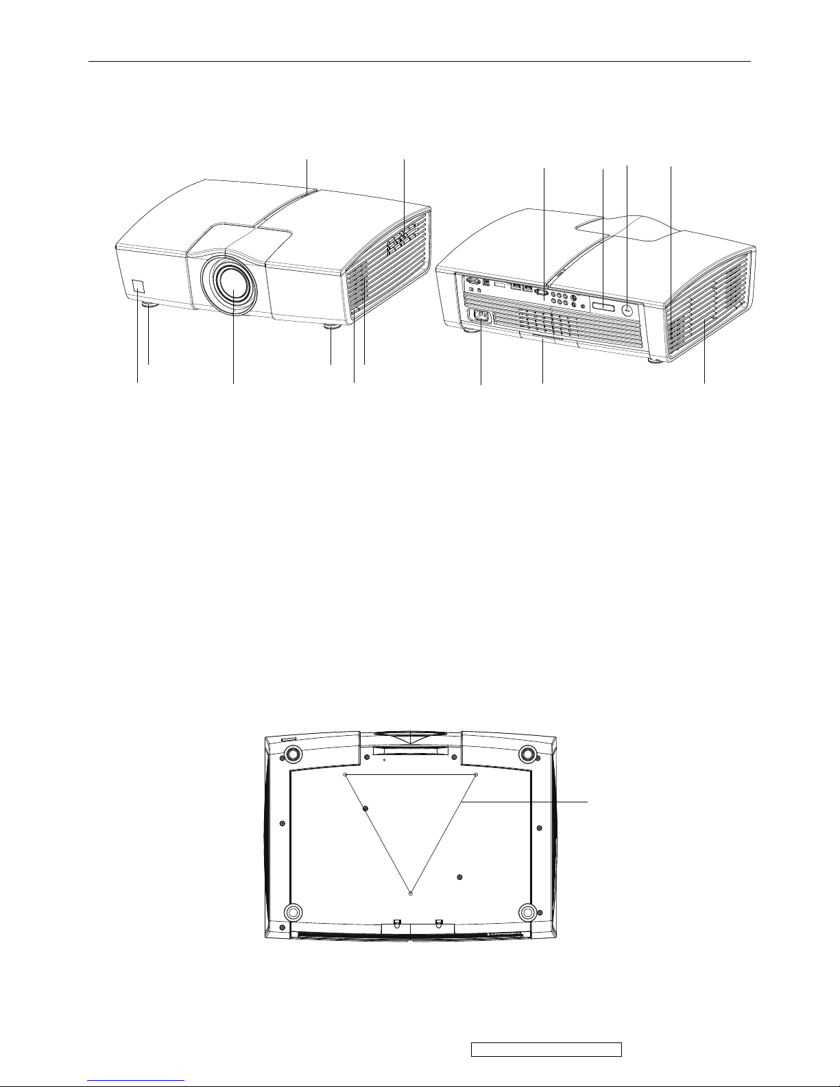
2. Front Panel Function Control Description
Location of features,Controls,and I/O
A. Projector overview
(3)
(6)
(5)(5)
(4) (11)(12)
(7) (8) (9) (10)(2) (1)
(13)(14)
1. Control panel
2. LED indicator
3. Air inlet grille
4. Front IR remote control sensor
5. Elevation foot
6. Elevation button
7. Connection ports
8. Rear IR remote control sensor
9. Kensington lock
10. Air outlet grille
11. Lamp cover
12. Air filter cover
13. AC power socket
14. Projection lens
15. Ceiling mount (3-M6)
(15)
5
ViewSonic Corporation Confidential - Do Not Copy PRO8100-1
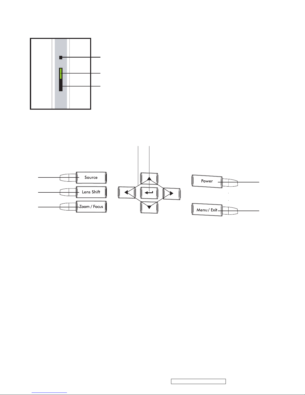
B.Control Panel
LED indicator:
(1)
(3)
(2)
1. Daylight sensor.
2. Power indicator
Refer to “LED Indicator Message” (Page 42).
3. Status indicator
Refer to “LED Indicator Message” (Page 42).
Button Function:
(4)
(5)
(6)
(7) (8)
(9)
(10)
4. Source
Manually selects an input source.
5. Lens Shift
Motorized vertical and horizontal lens
shift for positioning display image
without physically moving the unit.
6. Zoom/Focus
Motorized zoom and focus adjust.
7. Four directional buttons
Use four directional buttons to select items
or make adjustments to your selections.
8. Enter
To confirm selected menu item.
9. Power
Turn on or off the projector.
10. Menu/Exit
Opens and Exits the on-screen menu.
6
ViewSonic Corporation Confidential - Do Not Copy PRO8100-1
3. Circuit Description
Connector Information
This section provides each connector location on boards and function of each board. They will be
useful for your detecting the defective boards.
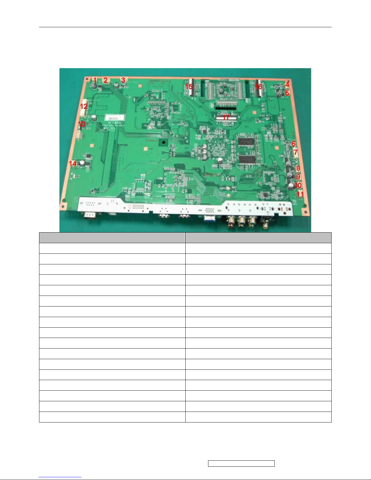
1. Main Board
Connector Description
No 1 Fan5, left fan housing
No 2 Connector, main board---motor board
No 3 Connector, optical engine---main board
No 4 Front IR
No 5 Fan6, right fan housing
No 6 Ballast control
No 7 Thermal sensor
No 8 Fan3
No 9 Fan2
No 10 Fan1
No 11 Back IR
No 12 12 Pin Power control
No 13 Keypad control(FPC)
No 14 Fan4
No 15 R FPCB
No 16 G FPCB
No 17 B FPCB
7
ViewSonic Corporation Confidential - Do Not Copy PRO8100-1
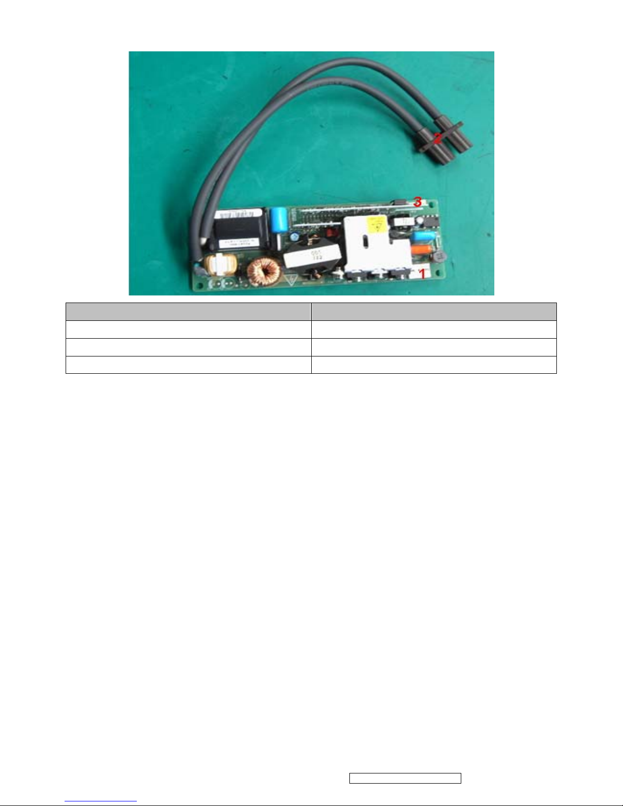
2. Ballast Board
Connector Description
No 1 Power supply
No 2 Lamp power supply
No 3 Ignite signal connected to Mainboard
8
ViewSonic Corporation Confidential - Do Not Copy PRO8100-1
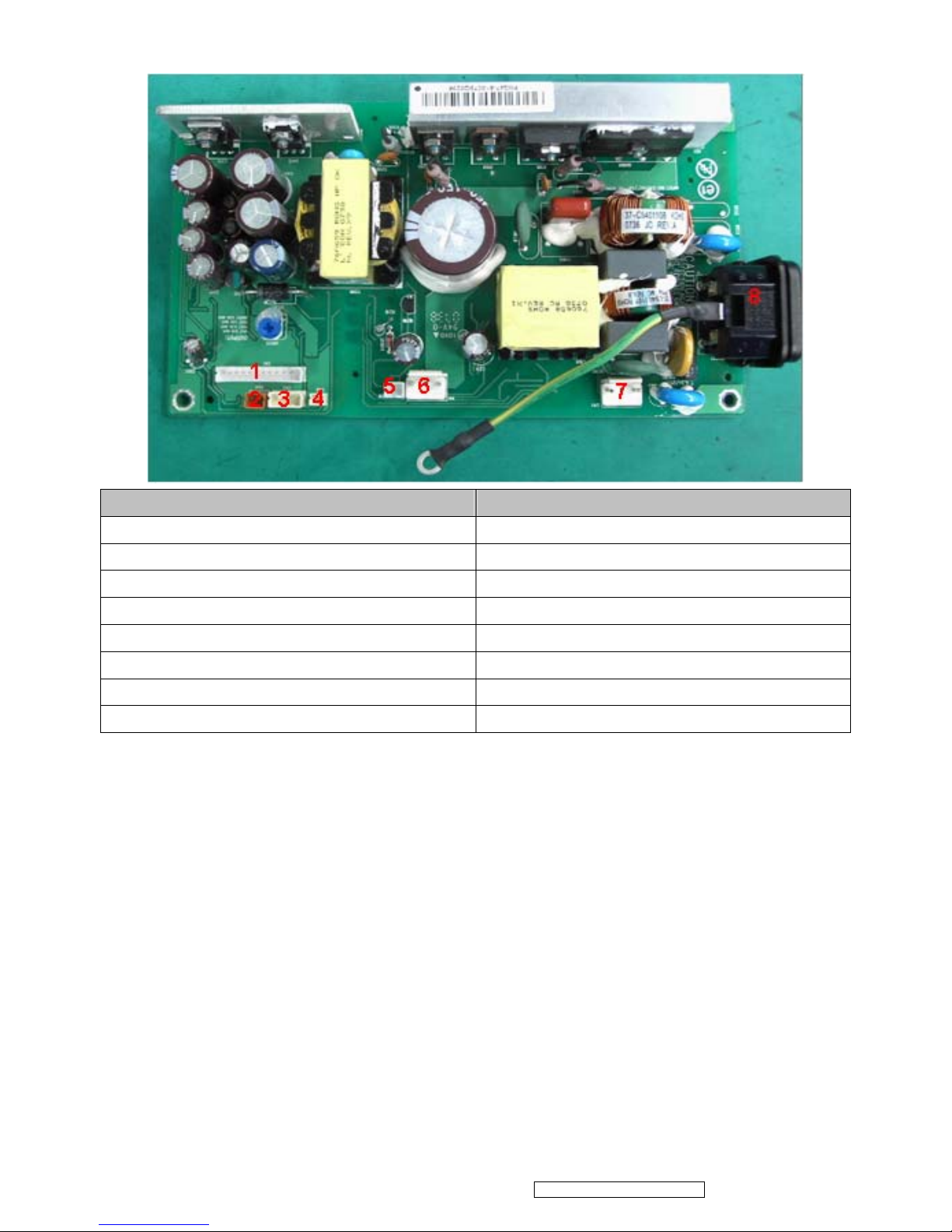
3. Power board
Connector Description
No 1 12-pin power control
No 2 2 pin wire (power board-motor board)
No 3 4 pin wire(power board-DC jack board)
No 4 2 pin wire (power board-DC jack board)
No 5 unused
No 6 380V power supply
No 7 thermostat
No 8 AC Input
9
ViewSonic Corporation Confidential - Do Not Copy PRO8100-1
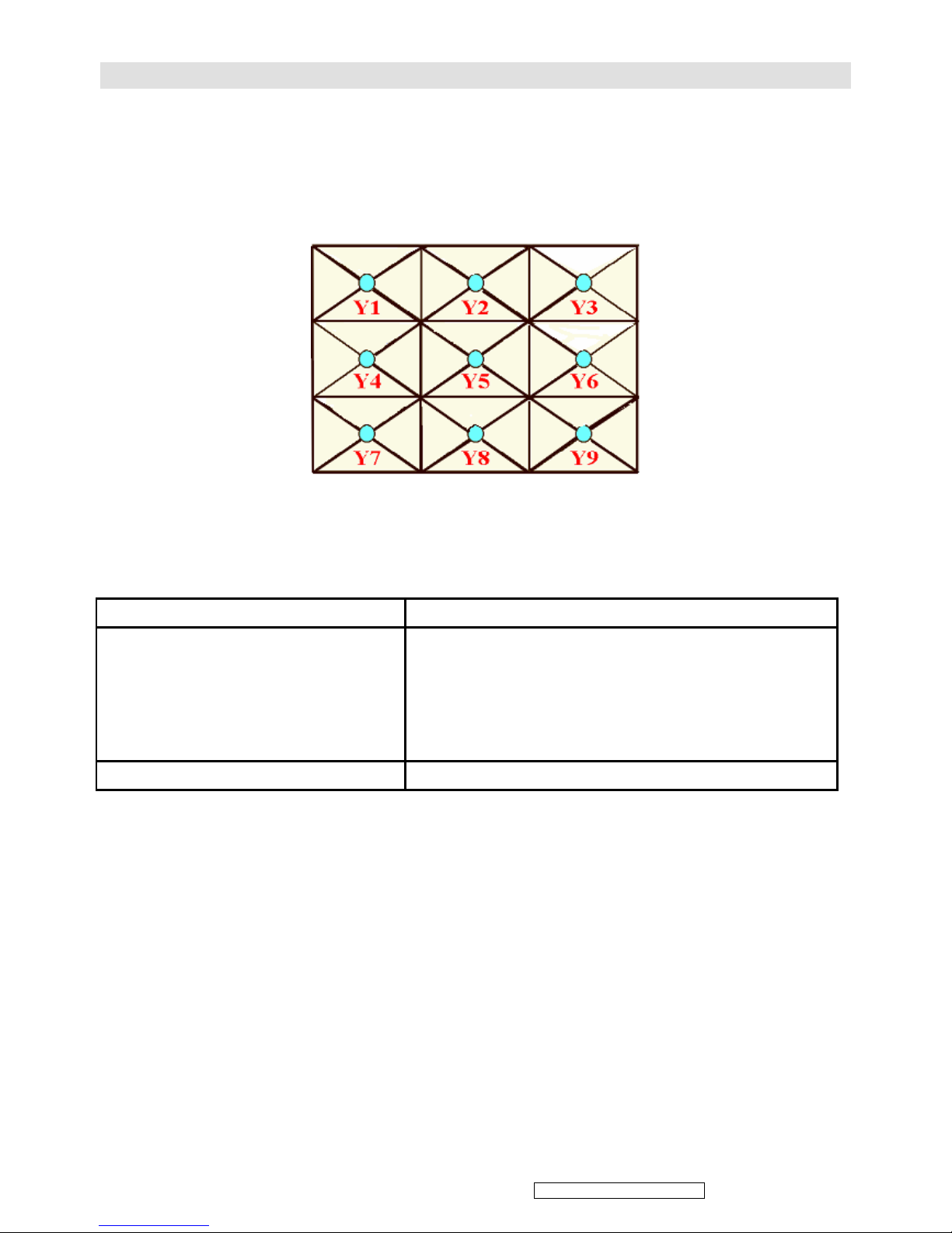
ANSI Lumen Measuring
Chroma 7600 Video Pattern Generator values
Set diaphragm to wide size
Projection test chart to 60 inches (projection distance 2m) and measurement 9 points
Measuring equation: Brightness = [(Y1+Y2+...+Y9)/9] × Projection ratio
DVI Pattern: 102
Appendix B: Service Level Definition
Level 1 : Cosmetic Parts ; Easy To Repair Lamp Module / Lens Cap assy
Level 2 : Module Replacement
Top Case assy / Low Case assy / Housing R Vent / Housing
L Vent assy / Ring Zoom / Lens Deco CVR / Lamp Door /
Power assy / Ballast Board assy / DC Jack Board / Motor
Board / Keypad assy / FAN assy / IR sensor assy /
thermal sensor
Level 3 : Board Level Repair or RTV Optical Engine (LCD Panel / lens )
Level 1: End user can replace by themselves
Level 2: Service Center
Level 3: RTV
10
ViewSonic Corporation Confidential - Do Not Copy PRO8100-1
Connection Definition
13-1. VGA IN
PIN DEFINITION
1 R/Pr
2 G/Y
3 B/Pb
4 Ground
5 Ground
6 Ground
7 Ground
8 Ground
9 VCC
10 Ground
11 WC-A
12 EDIDA-SDA
13 Hsync
14 Vsync
15 EDIDA-SCL
13-2. HDMI1
PIN DEFINITION
1 RX2+
2 Ground
3 RX2-
4 RX1+
5 Ground
6 RX1-
7 RX0+
8 Ground
9 RX0-
10 RXC+
11 Ground
12 RXC-
13 HDA_CEC
14 NC
15 HDA_SCL
16 HDA_SDA
17 Ground
18 +5V
19 PLUGA_DET
13-3. HDMI2
PIN DEFINITION
1 RX2+
2 Ground
3 RX2-
4 RX1+
5 Ground
6 RX1-
7 RX0+
8 Ground
9 RX0-
10 RXC+
11 Ground
12 RXC-
13 HDB_CEC
14 NC
15 HDB_SCL
16 HDB_SDA
17 Ground
18 +5V
19 PLUGB_DET
13-4. USB
PIN DEFINITION
1 VBUS
2 USB_DP
3 USB_DM
4 Ground
5 Ground
6 Ground
ViewSonic Corporation Confidential - Do Not Copy PRO8100-1
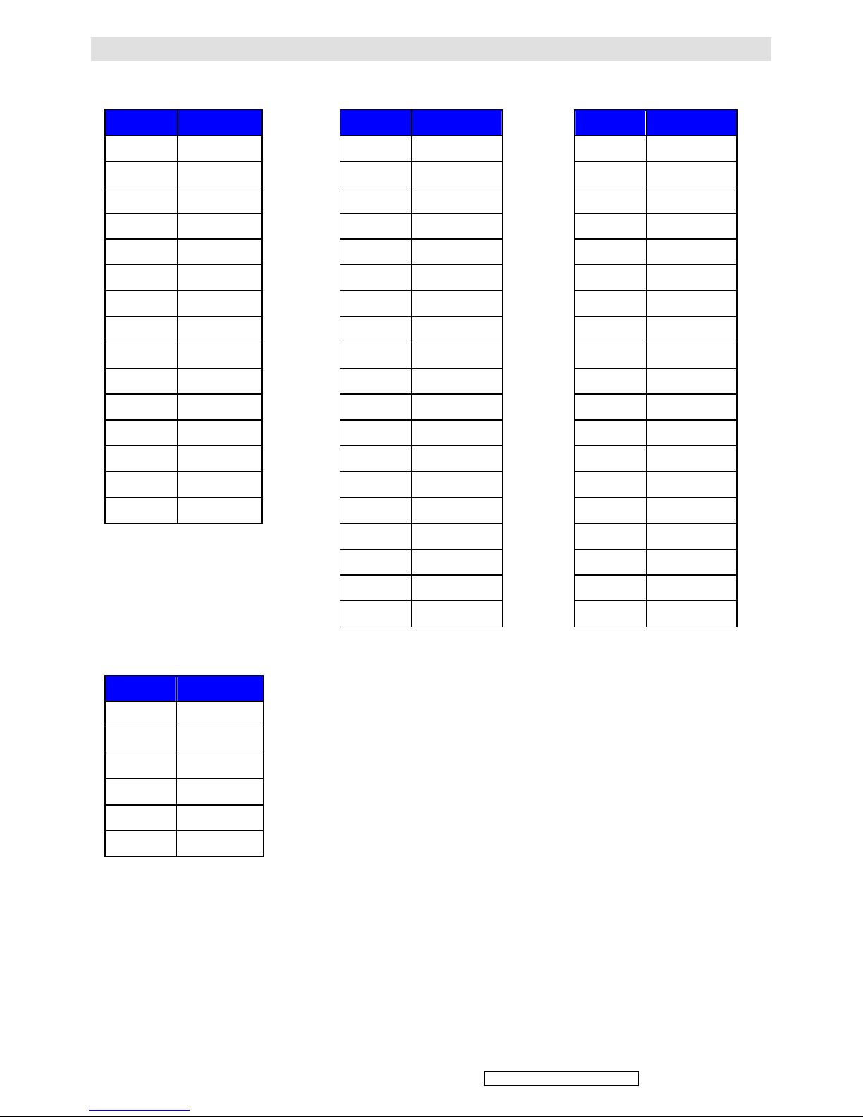
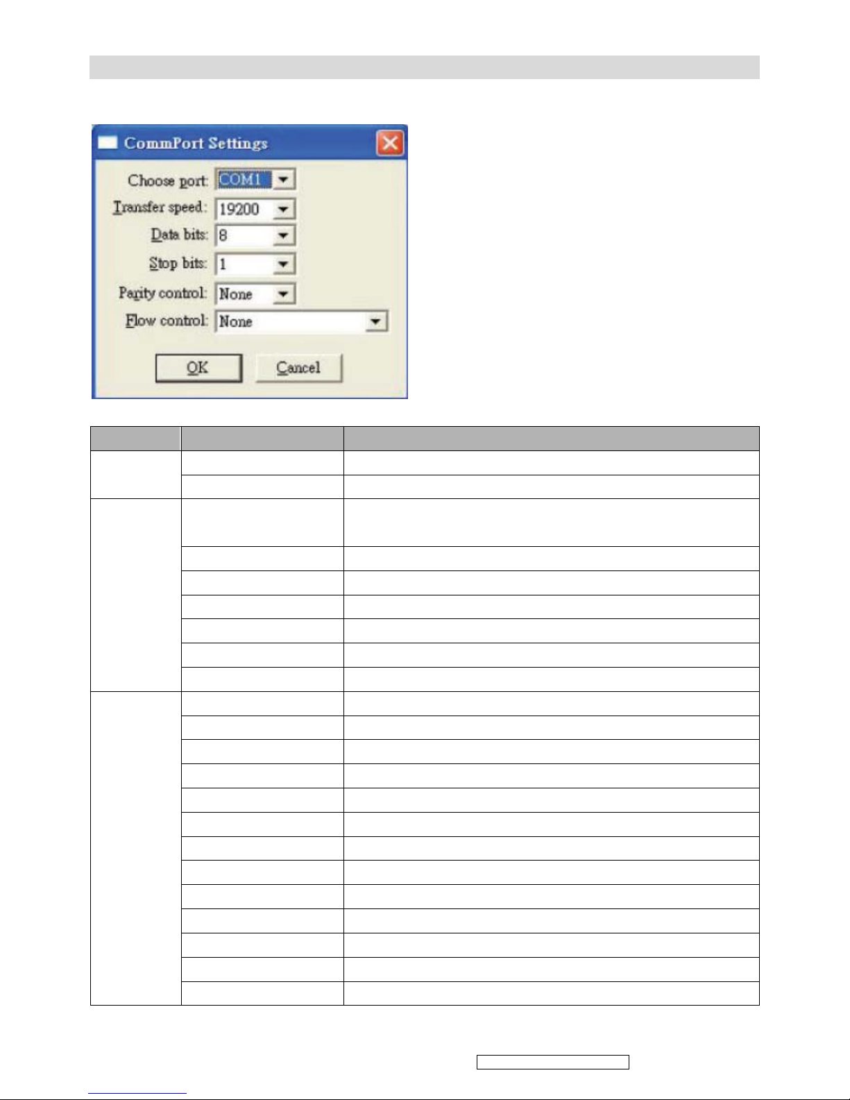
RS232 Command
1.protocol setting
2.RS-232 Command and Configuration
Name Operation type Send String (HEX)
ON
BE EF 10 05 00 C6 FF 11 11 01 00 01 00
power
OFF
BE EF 02 06 00 57 D0 2E 00 00 00 00 00
Computer (Analog
RGB1)
BE EF 02 06 00 0B D2 32 00 00 00 00 00
Component 1
BE EF 02 06 00 DA D3 33 00 00 00 00 00
Component 2
BE EF 02 06 00 85 DA 5C 00 00 00 00 00
S-Video
BE EF 02 06 00 6D D2 34 00 00 00 00 00
Composite Video
BE EF 02 06 00 BC D3 35 00 00 00 00 00
HDMI-1
BE EF 02 06 00 8F D3 36 00 00 00 00 00
source
HDMI-2
BE EF 02 06 00 5E D2 37 00 00 00 00 00
Picture mode
BE EF 02 06 00 3B D9 42 00 00 00 00 00
Color Temp
BE EF 02 06 00 EA D8 43 00 00 00 00 00
Aspect Ratio
BE EF 02 06 00 5D D9 44 00 00 00 00 00
Menu
BE EF 02 06 00 8C D8 45 00 00 00 00 00
Exit
BE EF 02 06 00 BF D8 46 00 00 00 00 00
Up
BE EF 02 06 00 6E D9 47 00 00 00 00 00
Down
BE EF 02 06 00 91 D9 48 00 00 00 00 00
Left
BE EF 02 06 00 40 D8 49 00 00 00 00 00
Right
BE EF 02 06 00 73 D8 4A 00 00 00 00 00
PCS
BE EF 02 06 00 A2 D9 4B 00 00 00 00 00
Daylight Sensor
BE EF 02 06 00 15 D8 4C 00 00 00 00 00
Overscan
BE EF 02 06 00 C4 D9 4D 00 00 00 00 00
Key-Pad &
IR
command
Black level
BE EF 02 06 00 F7 D9 4E 00 00 00 00 00
11
ViewSonic Corporation Confidential - Do Not Copy PRO8100-1
HQV
BE EF 02 06 00 26 D8 4F 00 00 00 00 00
Freeze
BE EF 02 06 00 49 DA 50 00 00 00 00 00
Input
BE EF 02 06 00 98 DB 51 00 00 00 00 00
V/H keystone
BE EF 02 06 00 AB DB 52 00 00 00 00 00
Lens shift Right
BE EF 02 06 00 54 DB 5D 00 00 00 00 00
Lens shift Left
BE EF 02 06 00 67 DB 5E 00 00 00 00 00
Lens shift Up
BE EF 02 06 00 B6 DA 5F 00 00 00 00 00
Lens shift Down
BE EF 02 06 00 B9 DF 60 00 00 00 00 00
Focus +
BE EF 02 06 00 E3 DA 5A 00 00 00 00 00
Focus -
BE EF 02 06 00 32 DB 5B 00 00 00 00 00
Zoom +
BE EF 02 06 00 68 DE 61 00 00 00 00 00
Special
command
Zoom -
BE EF 02 06 00 5B DE 62 00 00 00 00 00
Error Code Get
BE EF 1A 0C 00 7A 46 4F 00 01 00 00 00 00 00
00 00 00 00
Filter Counter Get
BE EF 1A 0C 00 91 93 50 00 01 00 00 00 00 00
00 00 00 00
Temp Get
BE EF 1A 0C 00 52 6E 51 00 01 00 00 00 00 00
00 00 00 00
Lamp Life Get
BE EF 1A 0C 00 56 6A 52 00 01 00 00 00 00 00
00 00 00 00
Unit on time Get
BE EF 1A 0C 00 89 8B 5A 00 01 00 00 00 00 00
00 00 00 00
Data get
Return
1E — — — —
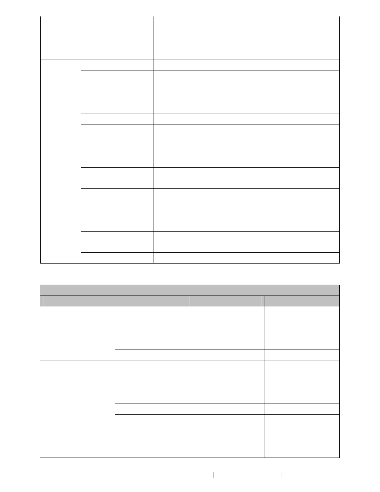
Compatible timing table
Analog PC timing
Mode Mode Resolution V-Sync H Sync
640 x 480 50Hz 24.69 kHz
640 x 480 60Hz 31.5 kHz
640 x 480 72Hz 37.9 kHz
640 x 480 75Hz 37.5 kHz
VGA
DOS/Text mode
visible
640 x 480 85Hz 43.3 kHz
800 x 600 50 Hz 30.99 kHz
800 x 600 56 Hz 35.2 kHz
800 x 600 60 Hz 37.9 kHz
800 x 600 72 Hz 48.1 kHz
800 x 600 75 Hz 46.9 kHz
SVGA
800 x 600 85 Hz 53.7 kHz
1024 x 768 50Hz 39.63 kHz
XGA
1024 x 768
60Hz 48.4 kHz
WXGA
1280x768 60 Hz 47.8 kHz
12
ViewSonic Corporation Confidential - Do Not Copy PRO8100-1
1280 x 1024 64.0 kHz 60 Hz
SXGA
1280 x 1024 80.0 kHz 75 Hz
Coordinated Video
Timing
640 x 480 67 Hz 35 kHz
832 x 624 75 Hz 49.72 kHz
1024 x 768 75 Hz 60.24 kHz
Others
1280 x 720 60 Hz 45.1 kHz
1280 x 800 60 Hz 49.7 kHz
1280 x 800 75 Hz 62.8 kHz
1280 x 800 85 Hz 71.6 kHz
1360 x 768 60 Hz 47.7 kHz
1400 x 1050 60 Hz 65.3 kHz
1440 x 900 60 Hz 55.9 kHz
1600 x 1200 60 Hz 75 kHz
1680 x 1050 60 Hz 65.3 kHz
1920 x 1080 60 Hz 33.8 kHz
1920 x 1080 60 Hz 67.5 kHz
Digital PC timing (HDMI)
Mode Mode Resolution V-Sync H Sync
VGA (DOS/Text mode
visible)
640 x 480 60 Hz 31.5 kHz
480p 720 x 483 60 Hz 31.5 kHz
SVGA 800 x 600 60 Hz 37.9 kHz
XGA 1024 x 768 60 Hz 48.4 kHz
720p 1280 x 720 60 Hz 45 kHz
WXGA 1280 x 768 60 Hz 47.8 kHz
SXGA
1280 x 1024 60 Hz 64.0 kHz
SXGA+ 1400 x 1050 60 Hz 65.3 kHz
WSXGA+ 1680 x 1050 60 Hz 65.3 kHz
1080i 1920 x 1080 60 Hz 33.8 kHz
1080p 1920 x 1080 60 Hz 67.5 kHz
UXGA 1600 x 1200 60 Hz 75 kHz
Others
1280 x 800 60 Hz 49.7 kHz
1280 x 960 60 Hz 60.0 kHz
1360 x 768 60 Hz 47.7 kHz
1440 x 900 60 Hz 55.9 kHz
Compatible/Supportive timing
Note: the Projector may need minor adjustment in the OSD to get optimized performance,
13

ViewSonic Corporation Confidential - Do Not Copy PRO8100-1
when below video signals is input to it through the HDMI connector.
480i60 720x480 60 15.8k
480p60 720x480 60 31.5k
576i50 720x576 50 15.6k
576p50 720x576 50 31.3k
720p50 1280x720 50 37.5k
720p60 1280x720 60 45.0k
1080i50 1920x1080 50 28.1k
1080i60 1920x1080 60 33.8k
1080p50 (Native) 1920x1080 50 56.3k
1080p60 (Native) 1920x1080 60 67.5k
14

15
ViewSonic Corporation Confidential - Do Not Copy PRO8100-1
4. Adjustment Procedure
Firmware Upgraded Flow
This chapter provides the information regarding relevant equipments and upgrading procedure
for LCD projector firmware upgrade.
Note:
Firmware upgrade process is not necessary. Please check the firmware and composer version
before any procedures. During firmware download period, please do not shut down PC or
projector, this will cause flash memory’s damage. And need to return the unit to manufacturer for
flash memory recovery.
Setup Tool/Equipment
Computer
USB Cable
Power Cord
Upgrading Procedure
1. Connect USB cables on NB/PC and Pro8100.
2. To get into Service mode: Press on the Menu button then press Power button. (The Top
LED will flash quickly)
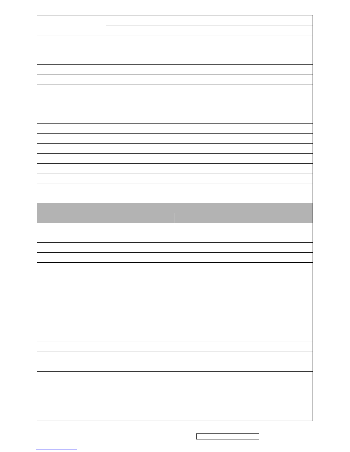
3. Open “Pro8100 Updater” file
16
ViewSonic Corporation Confidential - Do Not Copy PRO8100-1
4. Execute “Updater.exe” file on the PC.
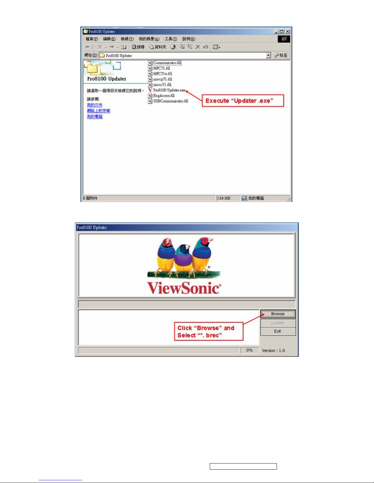
5. Click on the Browse button and browse the “xxxxx.brec” file.
17
ViewSonic Corporation Confidential - Do Not Copy PRO8100-1
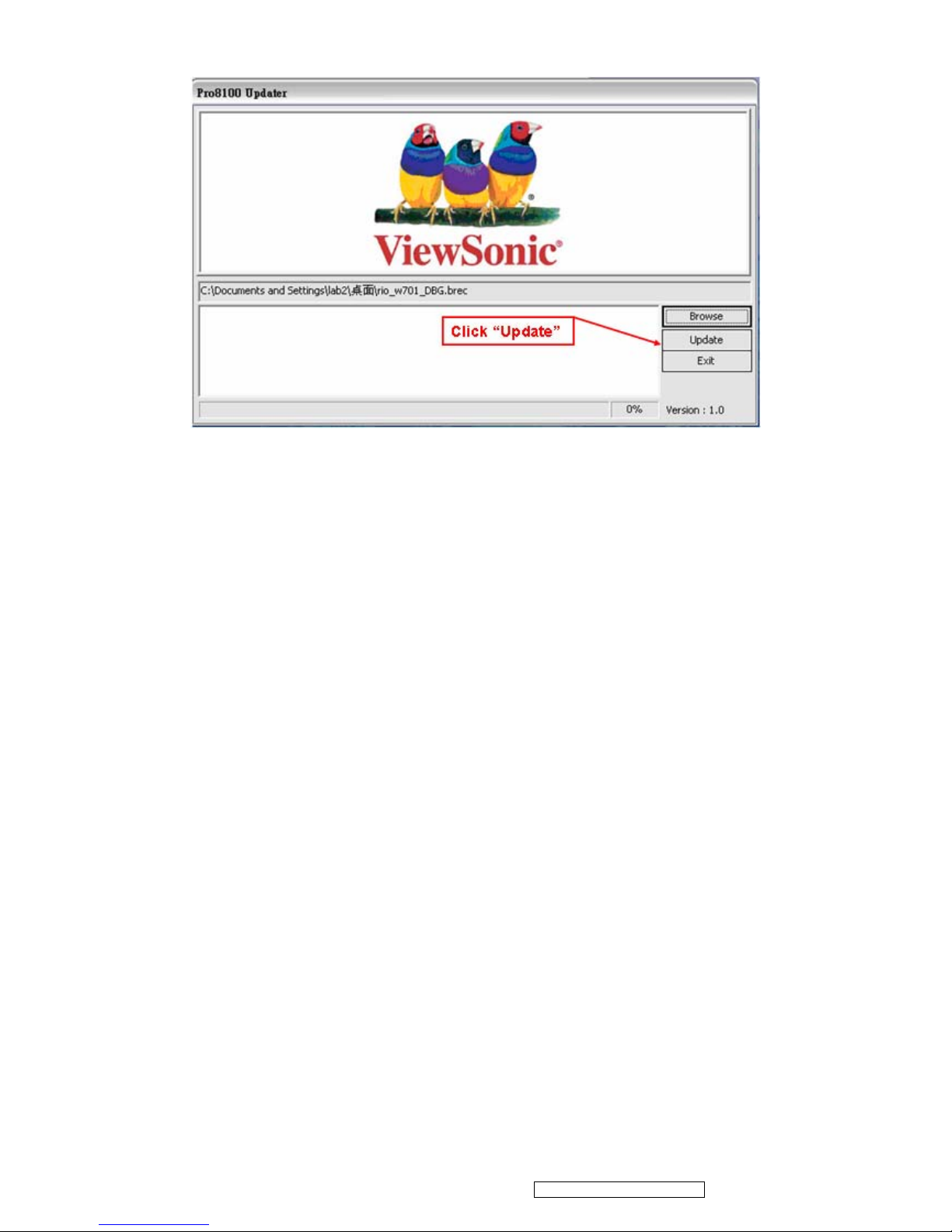
6. Press Update button to upload the F/W into Pro8100.
7. After Firmware upgrades completed. Press Exit button to exit the updater. Remove USB
cable and power cable.
18
ViewSonic Corporation Confidential - Do Not Copy PRO8100-1
Jepico F/W update procedure
2.3 Setup Tool/Equipment
Computer
USB Cable
Power Cord
2.4 Upgrading Procedure
Installing Writer SPI-ROM for L0046 Software
Notice
JEPICO Co owns the sole copyright to this software. You may not make a copy of this software. No part of this
document may be produced or transmitted in any form or by any information storage and retrieval system without
written permission from JEPICO Co.
System Requirements
■ Microsoft Windows XP must be installed.
■ Monitor supporting 1024 X 768 or greater resolution with at least 256 colors.
■ 10/100 Mb Ethernet connection for downloading Microsoft .NET Framework 2.0.
■ Parallel port for programming SPI-ROM. If you use ROM programmer tool, not require Parallel Port.
Installation Procedure
<NOTE>:
This software requires Microsoft .NET Framework 2.0 via Internet. Please make sure your PC is connected to the
Internet.
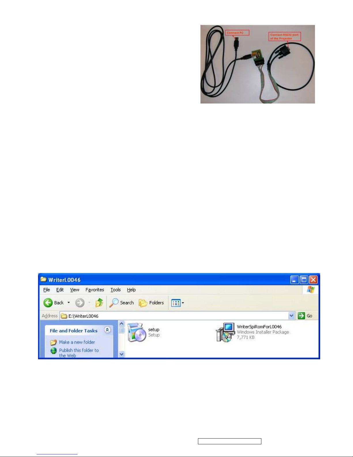
1. Install WriterSpiRomForL0046 software
(1) Double-click setup.exe icon in the Soft directory
19
ViewSonic Corporation Confidential - Do Not Copy PRO8100-1
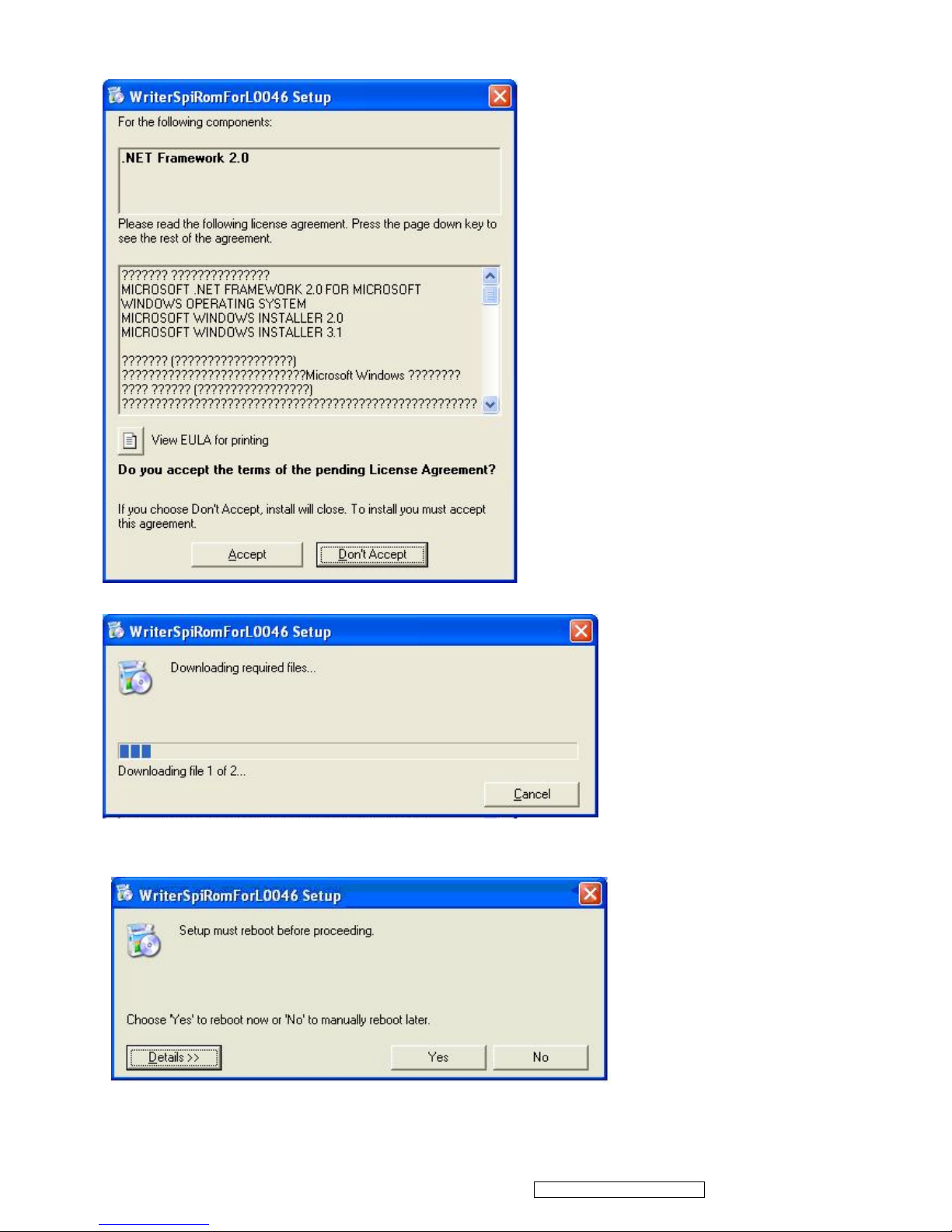
(2) Microsoft .NET Framework 2.0 installation wizard will launch. Click Accept.
(3) This installation may take about 5 minutes.
(4) After finish downloading, if you see following dialog, click Yes to reboot your PC.
If not require to reboot, you will see Welcome to the WriteSpiRom For L0046 Setup Wizard. Please go to (6).
20
ViewSonic Corporation Confidential - Do Not Copy PRO8100-1
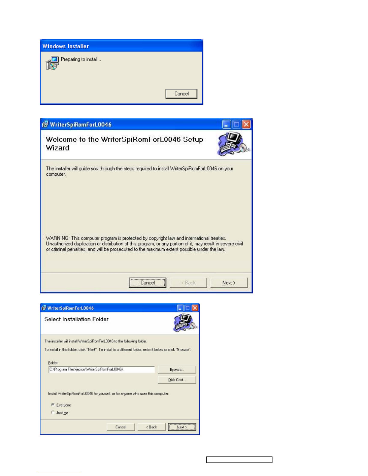
(5) After rebooting, following dialog will be automatically appeared. If not appeared, please double-click setup.exe
icon in the \Soft directory.
(6) Click Next.
(7) Select Installation Folder by Browse and Click Next.
21
ViewSonic Corporation Confidential - Do Not Copy PRO8100-1
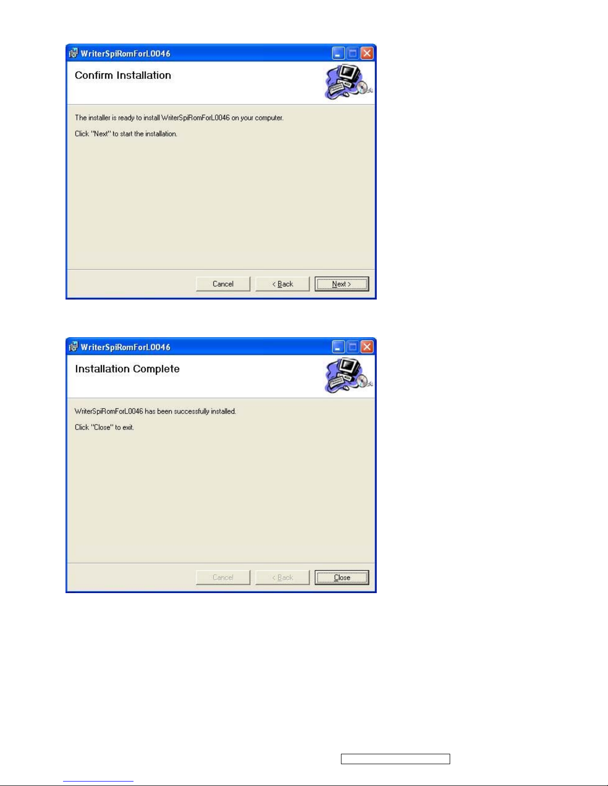
(8) Click Next.
(9) Click Close.
22
ViewSonic Corporation Confidential - Do Not Copy PRO8100-1
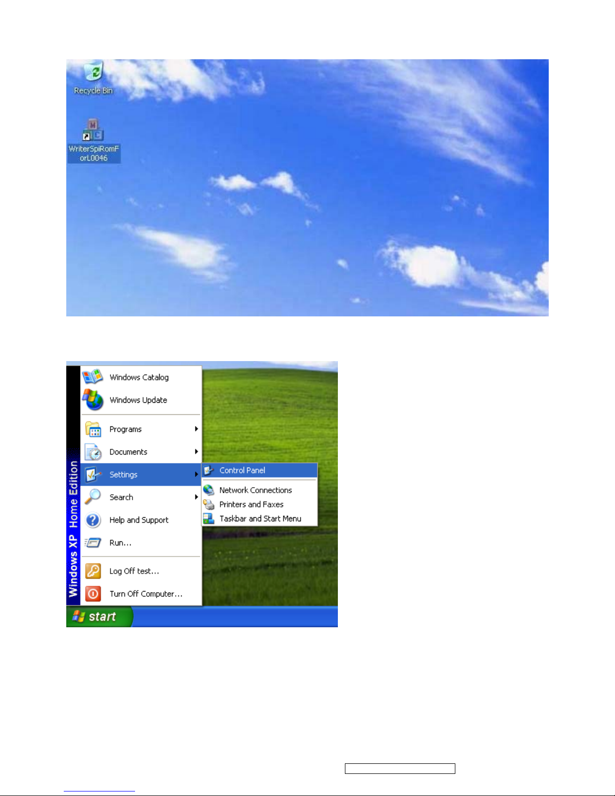
(10) After installation complete, short-cut icon will be appeared on the desk-top.
2. Install LPT Driver
If you use ROM programmer tool, LPT Driver installation is not required.
23
ViewSonic Corporation Confidential - Do Not Copy PRO8100-1
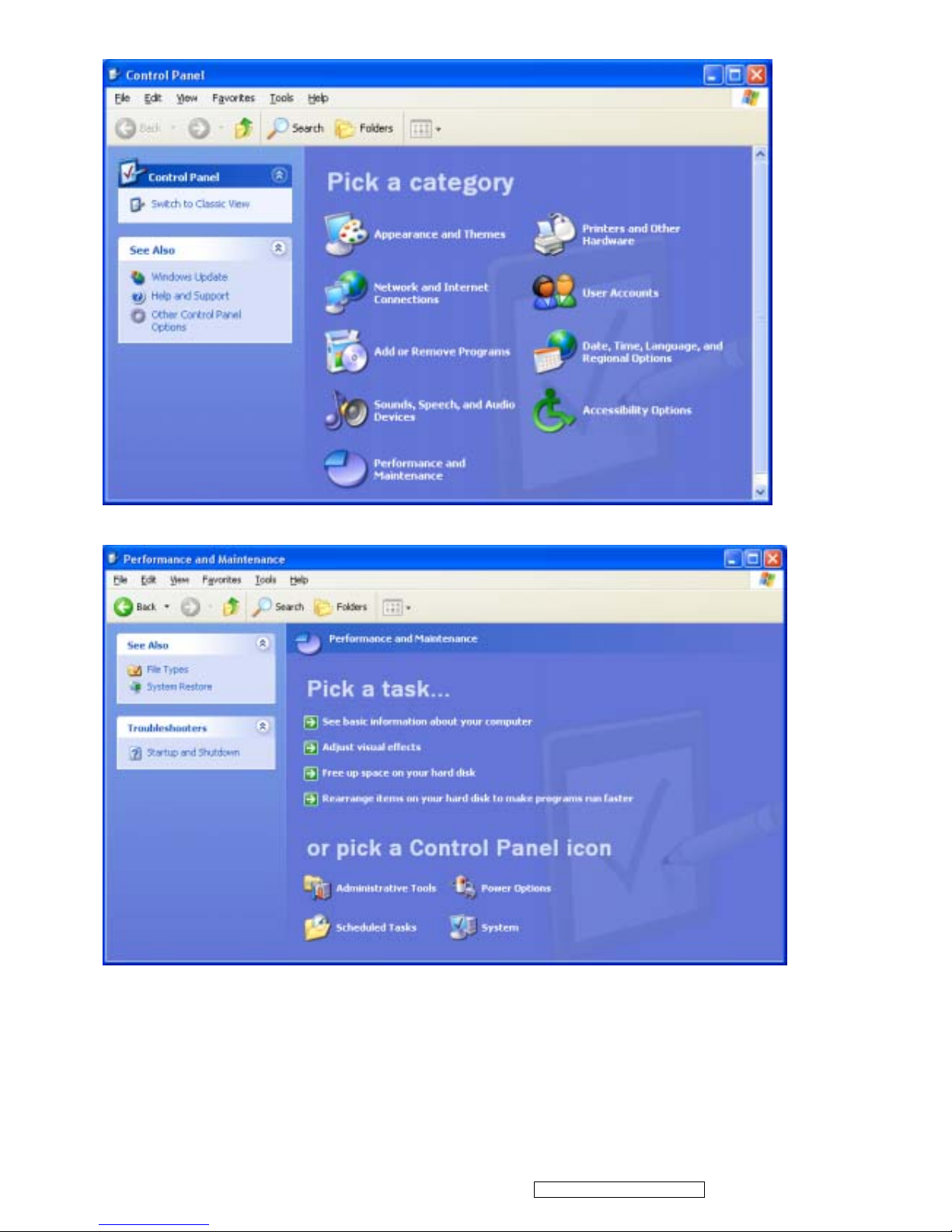
(2) Click the Performance and Maintenance icon.
(3) Click the System icon
24
ViewSonic Corporation Confidential - Do Not Copy PRO8100-1
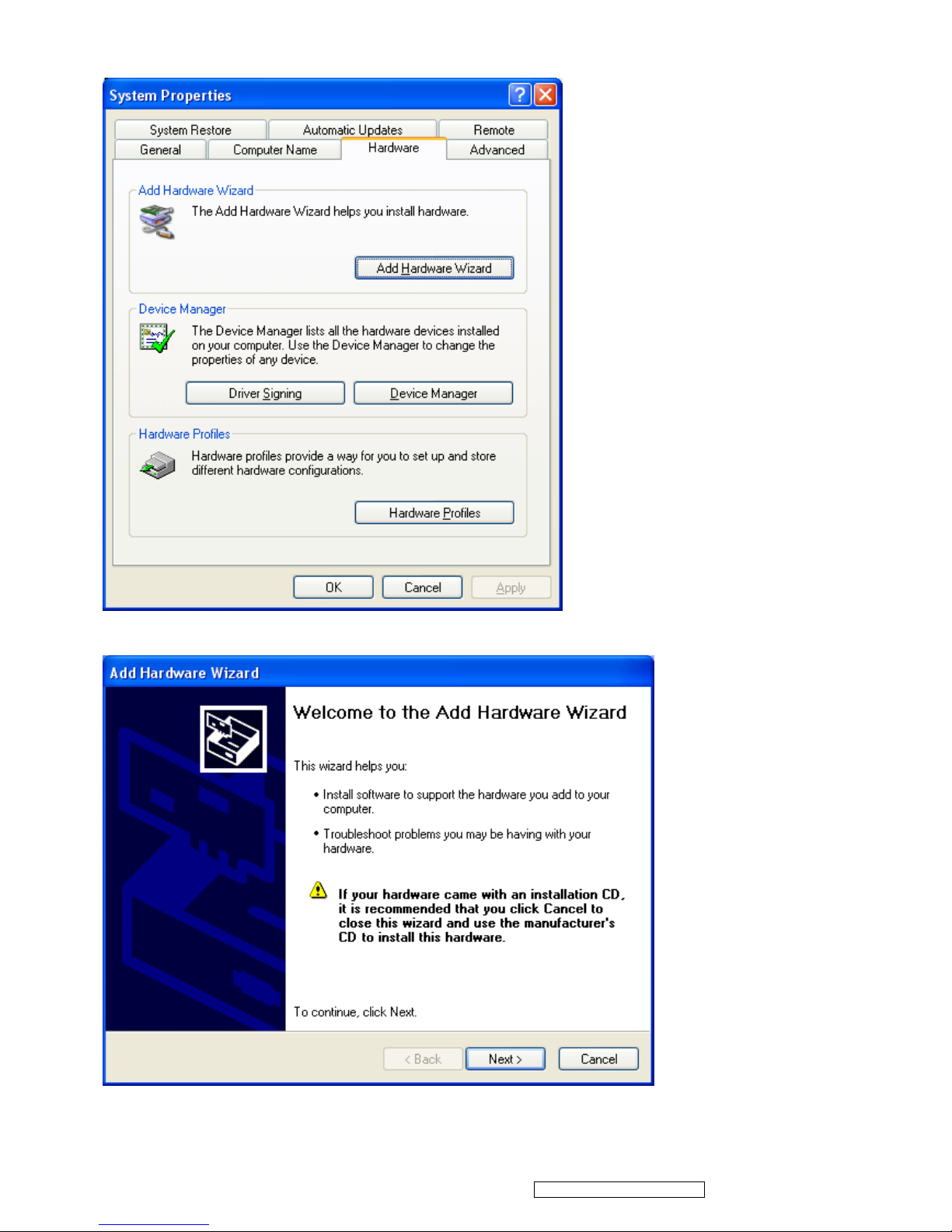
(4) Select Hardware menu and click Add Hardware Wizard.
(5) Click Next to continue.
25
ViewSonic Corporation Confidential - Do Not Copy PRO8100-1
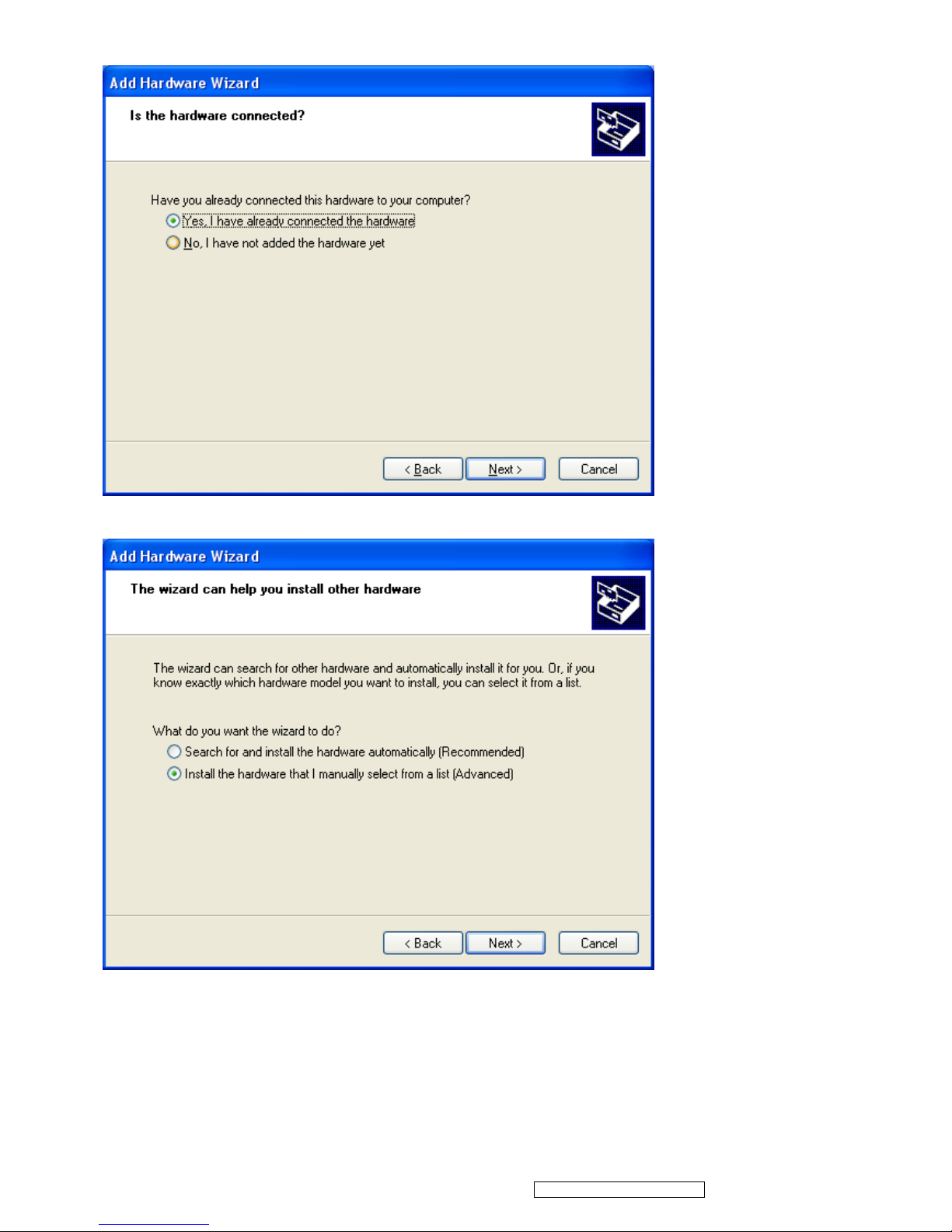
(6) Select Yes, I have already connected the hardware and click Next.
(8) Select Install the hardware that I manually select from a list (Advanced) and click Next to continue.
26
ViewSonic Corporation Confidential - Do Not Copy PRO8100-1
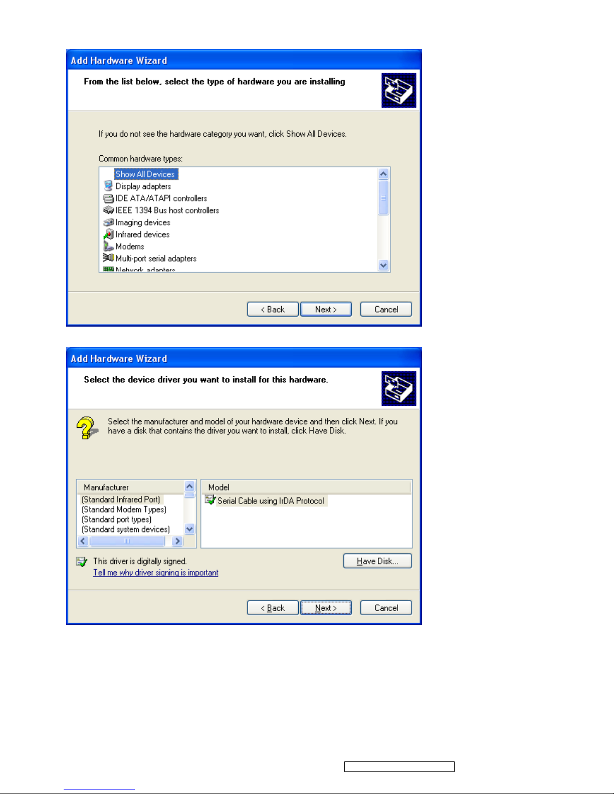
(9) Select Show All Devices and click Next to continue.
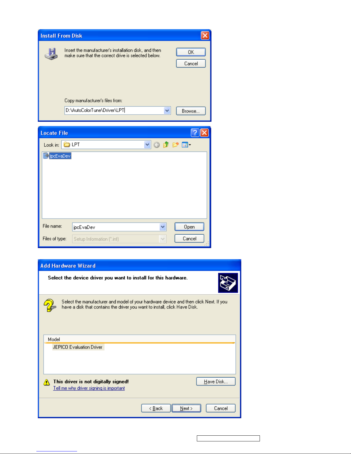
(10) Select Have Disk ....
27
ViewSonic Corporation Confidential - Do Not Copy PRO8100-1
(11) Browse to the jpcEvaDev.inf file in the \Driver \ LPT directory and click OK.
(12) Click Next to continue.
 Loading...