

Page 1

ViewSonic Q19wb-3
Model No. VS11578
19” Color TFT LCD Display
(Q19wb-3_SM Rev. 1a Oct. 2006)
ViewSonic 381 Brea Canyon Road, Walnut, California 91789 USA - (800) 888-8583
Service Manual
Page 2
ViewSonic Corporation Confidential - Do Not Copy Q19wb-3
i
Copyright
Copyright © 2006 by ViewSonic Corporation. All rights reserved. No part of this publication
may be reproduced, transmitted, transcribed, stored in a retrieval system, or translated into any
language or computer language, in any form or by any means, electronic, mechanical, magnetic,
optical, chemical, manual or otherwise, without the prior written permission of ViewSonic
Corporation.
Disclaimer
ViewSonic makes no representations or warranties, either expressed or implied, with respect to
the contents hereof and specifically disclaims any warranty of merchantability or fitness for any
particular purpose. Further, ViewSonic reserves the right to revise this publication and to make
changes from time to time in the contents hereof without obligation of ViewSonic to notify any
person of such revision or changes.
Trademarks
Optiquest is a registered trademark of ViewSonic Corporation.
ViewSonic is a registered trademark of ViewSonic Corporation.
All other trademarks used within this document are the property of their respective owners.
Revision History
Revision SM Editing Date ECR Number Description of Changes Editor
1a 10/31/2006 Initial Release Jamie Chang
Page 3
ViewSonic Corporation Confidential - Do Not Copy Q19wb-3
ii
TABLE OF CONTENTS
1. Precautions and Safety Notices 1
2. Specification 4
3. Front Panel Function Control Description 10
4. Circuit Description 12
5. Adjustment Procedure 20
6. Troubleshooting Flow Chart 42
7. Recommended Spare Parts List 46
8. Exploded Diagram and Exploded Parts List 48
9. Block Diagram 52
10. Schematic Diagrams 53
11. PCB Layout Diagrams 61
Page 4
ViewSonic Corporation Confidential - Do Not Copy Q19wb-3
1
1. Precautions and Safety Notices
1. Precaution & Safety Notice
1. Caution :
No modification of any circuit should be attempted . Service work should only be performed after you are thoroughly
familiar with all of the following safety checks and servicing guide line
2. Safety Check :
Care should be taken while servicing this LCD display. Because of the high voltage used in the inverter circuit. These
voltage are exposed in such areas as the associated transformer circuits .
3. POWER SUPPLY REQUIREMENTS
The external power converter for this display utilizes AC and DC cords , AC cord is detachable , but DC cord is
permanently attached . Any attempt to replace another adapter could result in serious problem on the display .
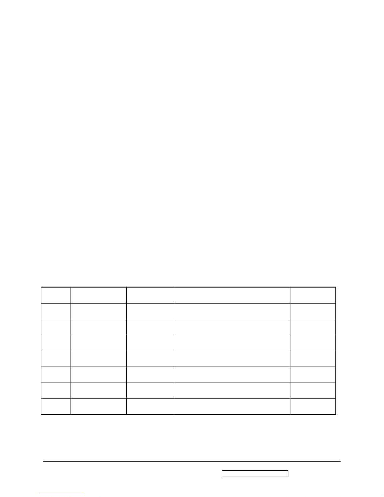
4. LEAKAGE CURRENT HOT CHECK
4-1 Plug the AC cord directly into the AC outlet. Do not use an isolation transformer during this check.
4-2 Connect a 1500 ohm , 10 watt resistor , paralleled by a 0.15uF capacitor between each metallic part and a good earth
ground
4-3 Use an AC voltmeter with 1000 ohm / volt or more sensitivity and measure the AC voltage across the combination
1500 ohm resistor and 0.15uF capacito r.
4-4 Move the resistor connection to each exposed metallic part and measure the voltage.
4-5 Reverse the polarity of the AC plug in the AC outlet and repeat the above measurement.
4-6 Voltage measured must not exceed 1.5 volt RMS, from any exposed metallic part to the ground. A leakage current
tester may be used in the above hot check, in which case any circuit measured must not exceed 1.0 milliamp. In the
case of a measurement exceeding the 1.0 milliamp value, a rework is required to eliminate the chance of a shock
hazard .
To Metal Parts
V
AC VOLTMETER
1500 10W
0.15u
.
Earth Ground
Page 5
ViewSonic Corporation Confidential - Do Not Copy Q19wb-3
2
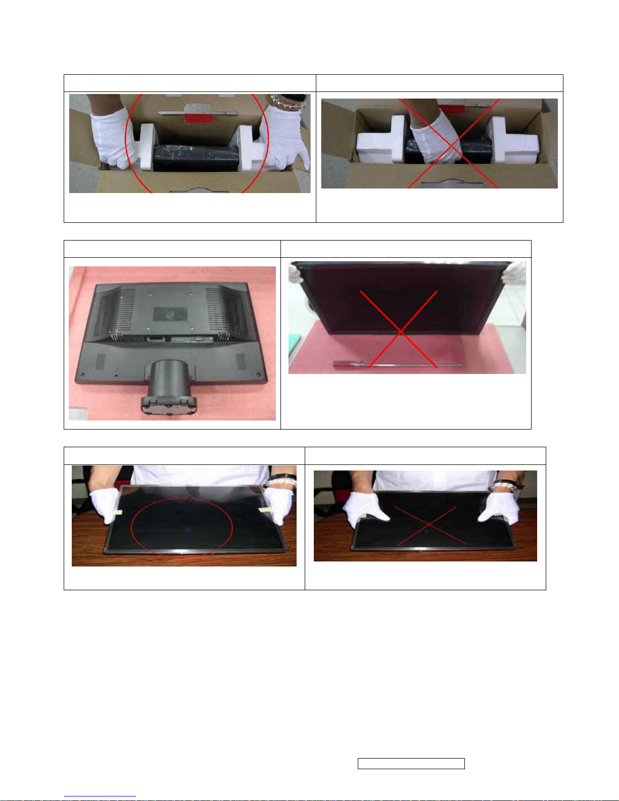
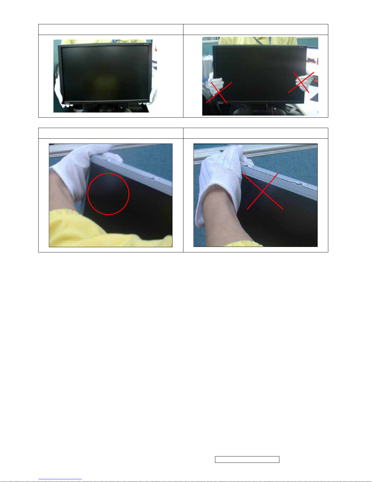
Q19wb-3 series handling Notice
Correct Method Incorrect method
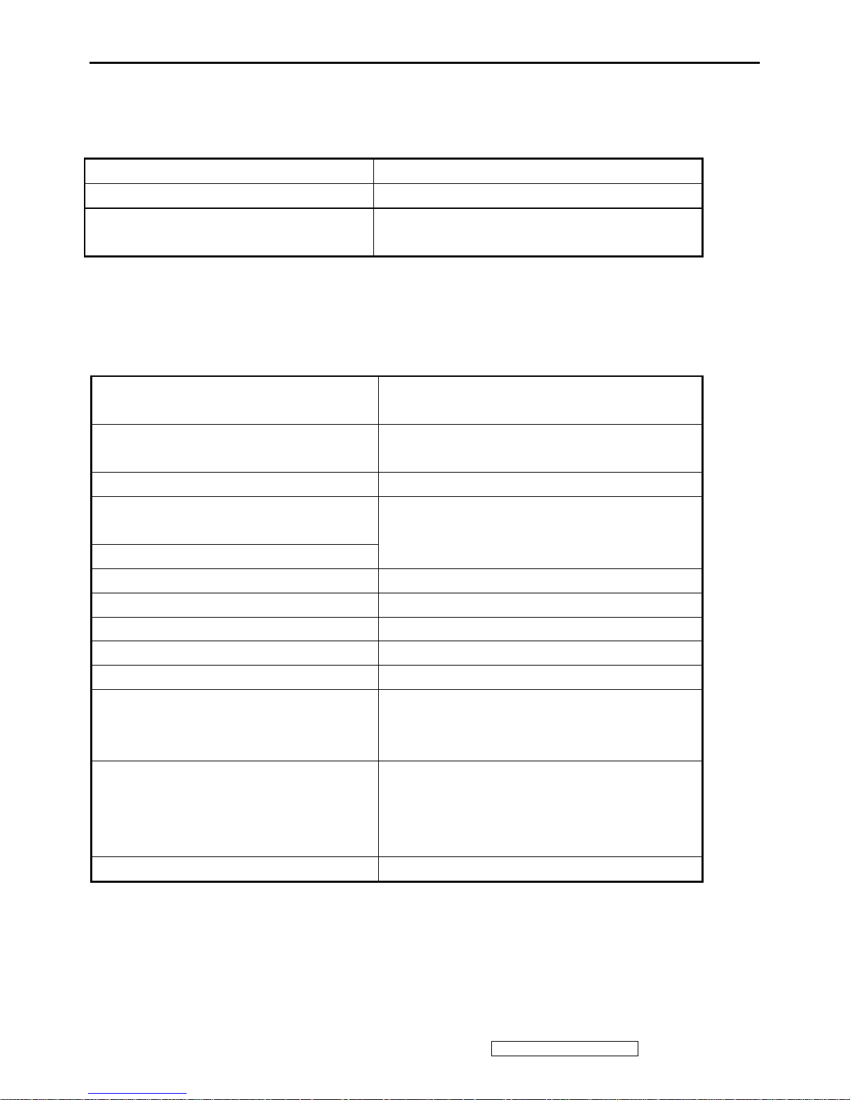
Correct Method Incorrect method
Correct Method Incorrect method
Page 6
ViewSonic Corporation Confidential - Do Not Copy Q19wb-3
3
Correct Method Incorrect method
Correct Method Incorrect method
Page 7
ViewSonic Corporation Confidential - Do Not Copy Q19wb-3
4
2. Specification
1. GENERAL REQUIREMENTS
General Specification
Test Resolution & Frequency 1440x900 @ 60Hz
Test Image Size Full Size
Contrast and Brightness Controls
Factory Default:
Contrast = 80%, Brightness = 100%
2. SIGNAL INTERFACE
Video Interface
Input Connector (refer the appendix A) D-Sub = DB-15 (Analog)
Default Input Connector D-Sub
Video Cable Strain Relief
Equal to twice the weight of the monitor for
five minutes
Video Cable Connector DB-15 Pin out Compliant DDC1/2B
Video RGB (Analog)
Video Signals
Separate Sync / SOG / Composite
Video Impedance 75 Ohms (Analog)
Maximum PC Video Signal 950 mV with no damage to monitor
Maximum Mac Video Signal 1250 mV with no damage to monitor
Sync Signals TTL
DDC/CI N/A
Sync Compatibility Separate Sync / Composite Sync / SOG
Video Compatibility
Shall be compatible with all PC type
computers, Macintosh computers, and after
market video cards
Resolution Compatibility
640 x 350, 640 x 400, 640 x 480, 720 x 400,
800 x 600, 832 x 624, 1024 x 768,
1152 x 864, 1152 x 870,1280 x 1024,
1440 x 900,
Exclusions Not compatible with interlaced video
Page 8
ViewSonic Corporation Confidential - Do Not Copy Q19wb-3
5
3. Power
Internal Power Supply Delta EADP-45AF BF
Input Volt age Range 90 to 264 VAC
Input Frequency Range 47.5 to 63 Hertz
Short Circuit Protection Output can be shorted without damage
Over Current Protection 5.0 A typical at 12.0 VDC
Leakage Current 0.75mA (Max) at 264VAC / 50Hz
Efficiency 75 % (min.)
Fuse Internal and not user replaceable
Power Dissipation 45 Watts (typ)
Max Input AC Current 1.2 Arms @ 90VAC, 0.7 Arms @264VAC
Inrush Current (Cold Start)
60 A (max) @ 115VAC
90A(Max)264VAC
Power Supply Cold Start
Shall start and function properly when under full load, with all
combinations of input voltage, input frequency, and operating
temperature.
Power Supply Transient Immunity
Shall be able to withstand an ANSI/IEEE C62.41-1980 6000V 200
ampere ring wave transient test with no damage.
Power Supply Line Surge Immunity
Shall be able to withstand 1.5 times nominal
line voltage for one cycle with no damage.
Power Supply Missing Cycle Immunity
Shall be able to function properly,without
reset or visible screen artifacts, when ½
cycle of AC power is randomly missing at
nominal input.
Power Supply Acoustics
The power supply shall not produce audible noise that would be
detectable by the user.
Audible shall defined to be in compliance with ISO 7779 (DIN
EN27779:1991) Noise
measurements of machines acoustics. Power
Switch noise shall not be considered.
Power Saving Operation(Method) VESA DPMS Signaling
On Mode < 40 W (Typ ) / 36 W (max)
Power Consumption
Active Off < 1 W
Recovery Time On Mode = N/A, Active Off < 5 sec
4. ELECTRICAL REQUIREMENTS
Horizontal /Vertical Frequency
Horizontal Frequency
31 – 81 kHz
Vertical Refresh Rate
50 – 75 Hz.
Maximum Pixel Clock 140 MHz
Sync Polarity Independent of sync polarity.
Timing Table
Analog Item Timing
Separated
Composite
SOG
Digital - TMDS
Remark
1 640 x 350 @ 70 Hz, 31.5 KHz
2 640 x 400 @ 70 Hz, 31.5 KHz
For Separated Sync, Switch
640x400@70Hz and 720x400@70Hz by
[AUTO]+[MENU]
short cut key (primary = 720x400@70Hz)
Page 9
ViewSonic Corporation Confidential - Do Not Copy Q19wb-3
6
3 640 x 480 @ 60 Hz, 31.5 KHz
4 640 x 480 @ 67 Hz, 35 KHz
5 640 x 480 @ 72 Hz, 37.9 KHz
6 640 x 480 @ 75 Hz, 37.5 KHz
7 720 x 400 @ 70 Hz, 31.5 KHz
8 800 x 600 @ 56 Hz, 35.1 KHz
9 800 x 600 @ 60 Hz, 37.9 KHz
10 800 x 600 @ 72 Hz, 48.1 KHz
1 1 800 x 600 @ 75 Hz, 49.6 KHz
12 832 x 624 @ 75 Hz, 49.7 KHz
13 1024 x 768 @ 60 Hz, 48.4 KHz
14 1024 x 768 @ 70 Hz, 56.5 KHz
15 1024 x 768 @ 72 Hz, 58.1 KHz
16 1024 x 768 @ 75 Hz, 60 KHz
17 1152 x 864 @ 75 Hz, 67.5 KHz
18 1152 x 870 @ 75 Hz, 68.7 KHz
19 1280 x 1024 @ 60 Hz, 64 KHz
20 1280 x 1024 @ 75 Hz, 80 KHz
21 1280 x 960 @ 60 Hz 59.7 KHz
22 1440 x 900 @ 60 Hz, 55.9 KHz
23 1440 x 900 @ 75 Hz, 70 KHz
Changing Modes
● Maximum Mode Change Blank Time for image stability : 3 seconds (Max), excluding “Auto Adjust” time
● Under DOS mode (640 x 350, 720 x 400 & 640 x 400), it should recall factory setting when execute “Auto
Adjust”
● The monitor needs to do “Auto Adjust” the first time a new mode is detected
(see section “0-Touch™ Function Actions”)
● While running Change Mode, Auto Adjust or Memory Recall, the image shall blank
Page 10
ViewSonic Corporation Confidential - Do Not Copy Q19wb-3
7
5. LCD Panel
1st Source Panel
Model number Hannstar HSD190MGW1-A00
Type Active Matrix TFT
Active Size 19.1"w
Pixel Arrangement RGB Vertical Stripe
Pixel Pitch 0.2835mm x 0.2835mm
Glass Treatment Anti-Glare
# of Backlights 4 CCFL
Backlight Life 50000 Hrs (Min)@6.5mA
300 cd/m2 (Typ after 30 minute warm up) Luminance (Center) –
CT = 6500K,
Contrast/ Brightness = Max
240 cd/m2 (Min after 30 minute warm up)
Brightness Uniformity 75% (min)
Contrast Ratio 700 :1 (Typ)
450 : 1 (Min)
Color Depth 16.2 million colors (6-bit+FRC panel)
Horizontal Viewing Angle 150 degrees (Typ) @ CR>10
130 degrees (Min) @ CR>10
Vertical Viewing Angle 140 degrees (Typ) @ CR>10
120 degrees (Min) @ CR>10
Response Time
On/Off
10%-90% @ Ta=25°C Typical = 5 ms (Tr = 1.5 ms; Tf = 3.5 ms)
Maximun = 10 ms (Tr = 3ms; Tf = 7ms)
Mercury 3.5 mg per lamp
Panel Defects Please see Panel Quality Specifications.
Page 11
ViewSonic Corporation Confidential - Do Not Copy Q19wb-3
8
2nd Source Panel
Model number Hannstar HSD190MGW1-A02
Type Active Matrix TFT
Active Size 19.1"w
Pixel Arrangement RGB Vertical Stripe
Pixel Pitch 0.2835mm x 0.2835mm
Glass Treatment Anti-Glare
# of Backlights 4 CCFL
Backlight Life 50000 Hrs (Min)@6.5mA
300 cd/m2 (Typ after 30 minute warm up) Luminance (Center) –
CT = 6500K,
Contrast/ Brightness = Max
240 cd/m2 (Min after 30 minute warm up)
Brightness Uniformity 75% (min)
Contrast Ratio 700 :1 (Typ)
450 : 1 (Min)
Color Depth 16.2 million colors (6-bit+FRC panel)
Horizontal Viewing Angle 150 degrees (Typ) @ CR>10
130 degrees (Min) @ CR>10
Vertical Viewing Angle 140 degrees (Typ) @ CR>10
120 degrees (Min) @ CR>10
Response Time
On/Off
10%-90% @ Ta=25°C Typical = 5 ms (Tr = 1.5 ms; Tf = 3.5 ms)
Maximun = 10 ms (Tr = 3ms; Tf = 7ms)
Mercury 3.5 mg per lamp
Panel Defects Please see Panel Quality Specifications.
Page 12
ViewSonic Corporation Confidential - Do Not Copy Q19wb-3
9
6. MECHANICAL.
Dimension (Desktop)
Width 446mm (17.6")
Height (Height adjust to the bottom) 364mm (14.3")
Depth 213.6mm (8.4")
Monitor Weight 4.4Kg (9.7 lbs)
*Refer to Figure 1
Dimension (Head Only / Wall Mount)
Width 446mm (17.6")
Height 292mm (11.5")
Depth 66.6mm (2.6")
Monitor Weight 4.0 Kg (8.8 lbs)
*Refer to Figure 1
Ergonomics
Tilt Up ≧ 20º
Tilt Down From 0º down to -3º ~ -5º
7. ENVIRONMENTAL
z Operating Temperature : 0°C to +40°C
z Storage Temperature : -20°C to +60°C
z Operating Relative Humidity : 20% to 90% RH Non-Condensing
z Storage Relative Humidity : 5% to 90% RH Non-Condensing
z Operating Altitude : 0 to +3,000 meters
z Storage Altitude : 0 to +12,000 meters
Page 13
ViewSonic Corporation Confidential - Do Not Copy Q19wb-3
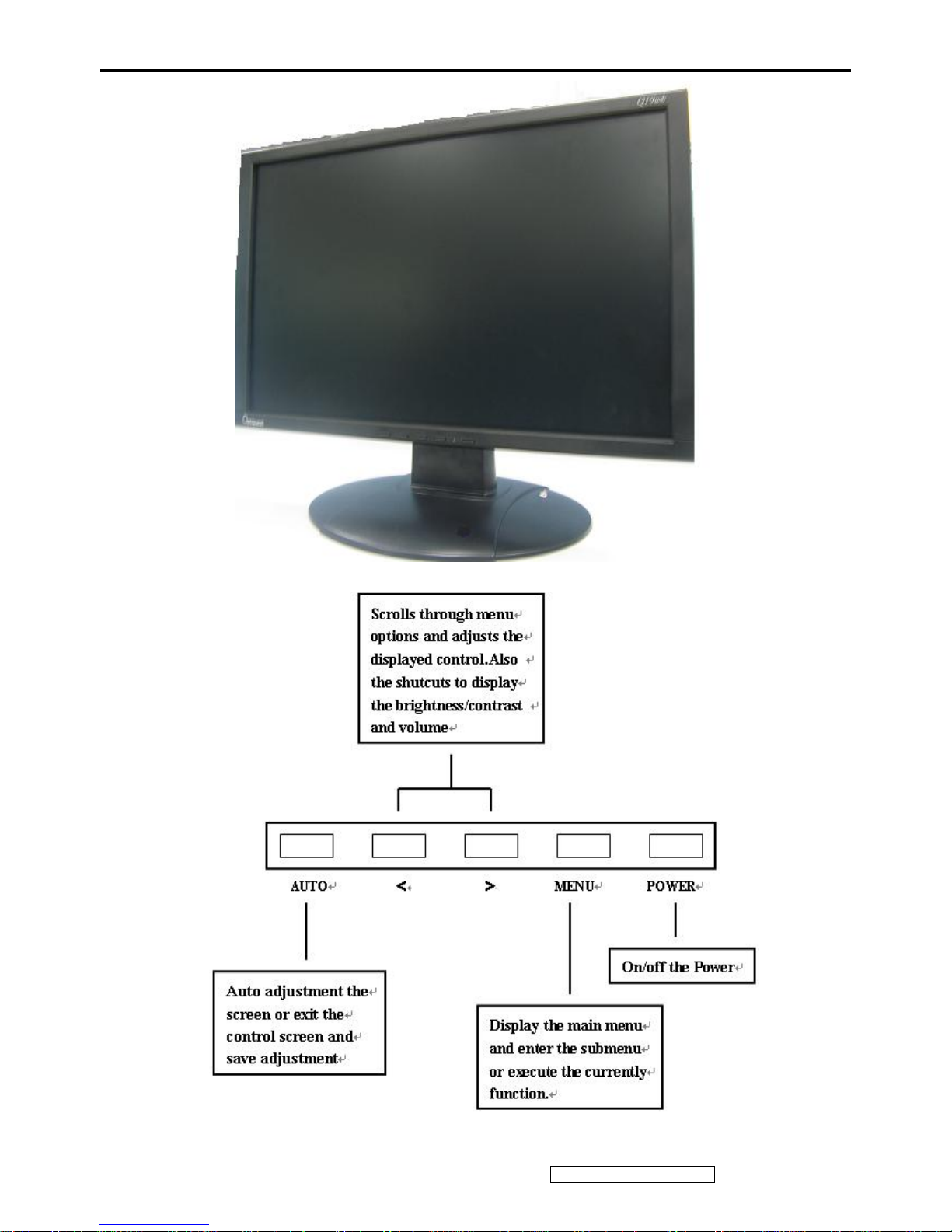
3. Front Panel Function Control Description
10
Page 14

ViewSonic Corporation Confidential - Do Not Copy Q19wb-3
11
Main Menu Controls
Adjust the menu items shown below by using the left and right buttons.
A. Brightness adjusts the lamps current to control the screen brightness.
B. Contrast adjusts the difference between the image background (black level) and the foreground (white level).
C. Image adjust controls are explained below:
Auto Adjustment automatically sizes, centers, clock ,phase and fine tunes the video signal to eliminate waviness and
distortion. Press the [menu] button to obtain a sharper image.
H./V. Position adjusts horizontal and vertical position of the screen image. You can toggle between Horizontal and
Vertical by pressing button [menu]. Horizontal moves the screen image to the left or to the right. Vertical moves the screen
image up and down.
Clock adjust Sets up the internal clock. Larger values make the displayed image appear wider; smaller values make it
appear compressed.
Phase adjust Adjusts the internal clock’s time lag in order to optimize the screen image.
Sharpness adjust
the clarity and focus of the screen image.
D. Color Adjust
provides several color options: preset color temperatures and Custom User Color which allows you to adjust
red (R), green (G), and blue (B). The factory setting for this product is 6500K (6500° Kelvin).
9300K — Adds blue to the screen image for cooler white (used in most office settings with fluorescent lighting).
5400K — Adds red to the screen image for warmer white and richer red.
Custom User Color — Individual adjustments for red, green, and blue.
1 To select color (R, G or B) press button [menu].
2 To adjust selected color, press [<] or [>]
.
3 When you are finished making all color adjustments, press button [Auto] twice.
E. OSD CONTROL controls are explained below:
H/V.OSD Position allows you to move the on-screen display menus and control screens.
OSD Timeout sets the length of time an on-screen display screen is displayed. For example, with a“15 second” setting,
if a control is not pushed within 15 seconds, the display OSD disappears.
F. Other Adjust
controls are explained below:
Language allows you to choose the language used in the menus and control screens.
Speaker volume allows you to increase or decrease the volume
.
Information there is an optional OSD window that displays the newly adjusted screen resolution settings.
G. Reset returns adjustments to the o riginal factory settings if the display is op erating in a factory Preset Timing Mode listed
in this user guide.
H. Exit allows you exit the OSD menu, press button [Menu].
Page 15
ViewSonic Corporation Confidential - Do Not Copy Q19wb-3
12
4. Circuit Description
1. Outline
1.1 Auto button, left arrow button, right arrow button, Menu button, Power button on the front panel.
1.2 D-sub 15pin connector, audio line-in receptacle, and AC-IN are located on the back side of the cabinet.
1.3 OSD menu includes the following function;
(1)Brightness& Contrast adjusts
(2) Image Adjust
(3) Color Adjust
(4) OSD Control
(5) Other Adjust
(6) Reset
(7) Exit
1.4 Speaker Volume & the control bar is adjustable by [<], [>] button. Mute or Speaker [MENU] key when speaker
volume OSD appear
Audio volume can be controlled with right arrow button when Audio Adjust menu is acti ve.
2. CONNECTORS
2.1 AC inlet : CEE7-7 typed connector
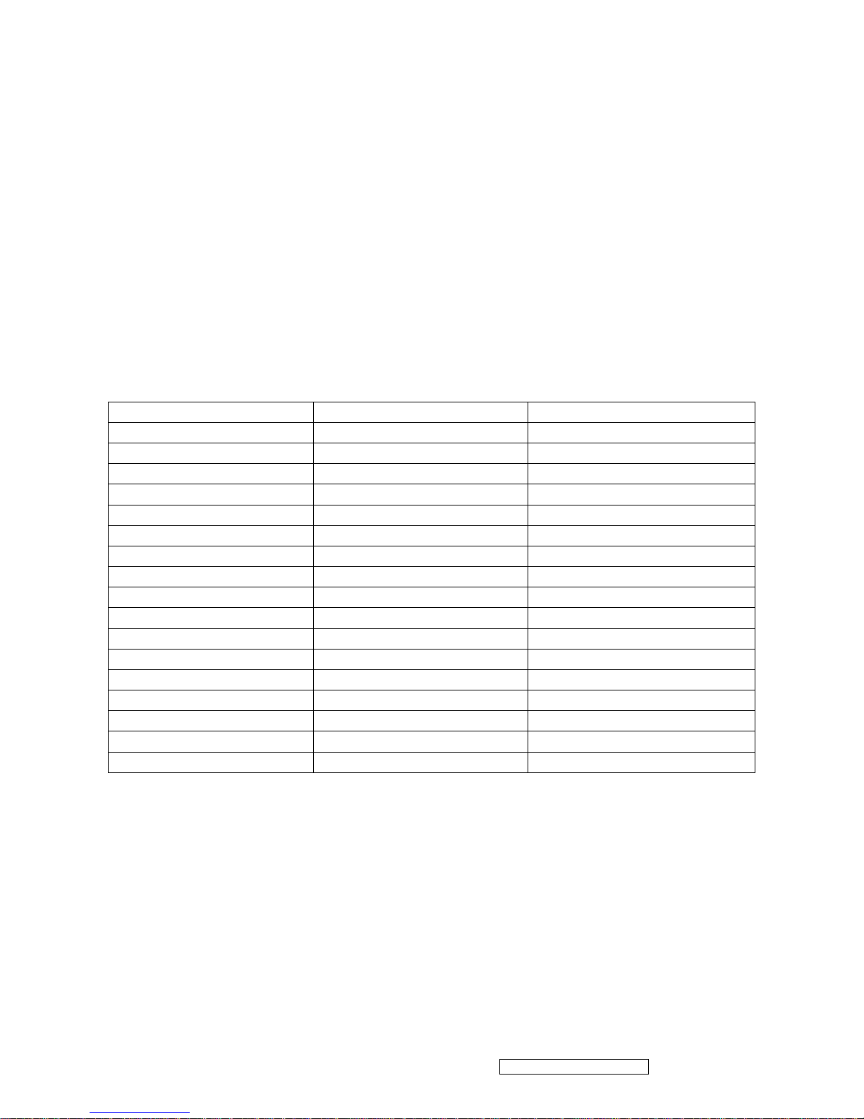
2.2 Audio : Line-in,
AJ1
PHONE JACK 5P (ZD005D100)
2
3
4
5
1
Line-in receptacle
(Line-in receptacle is green)
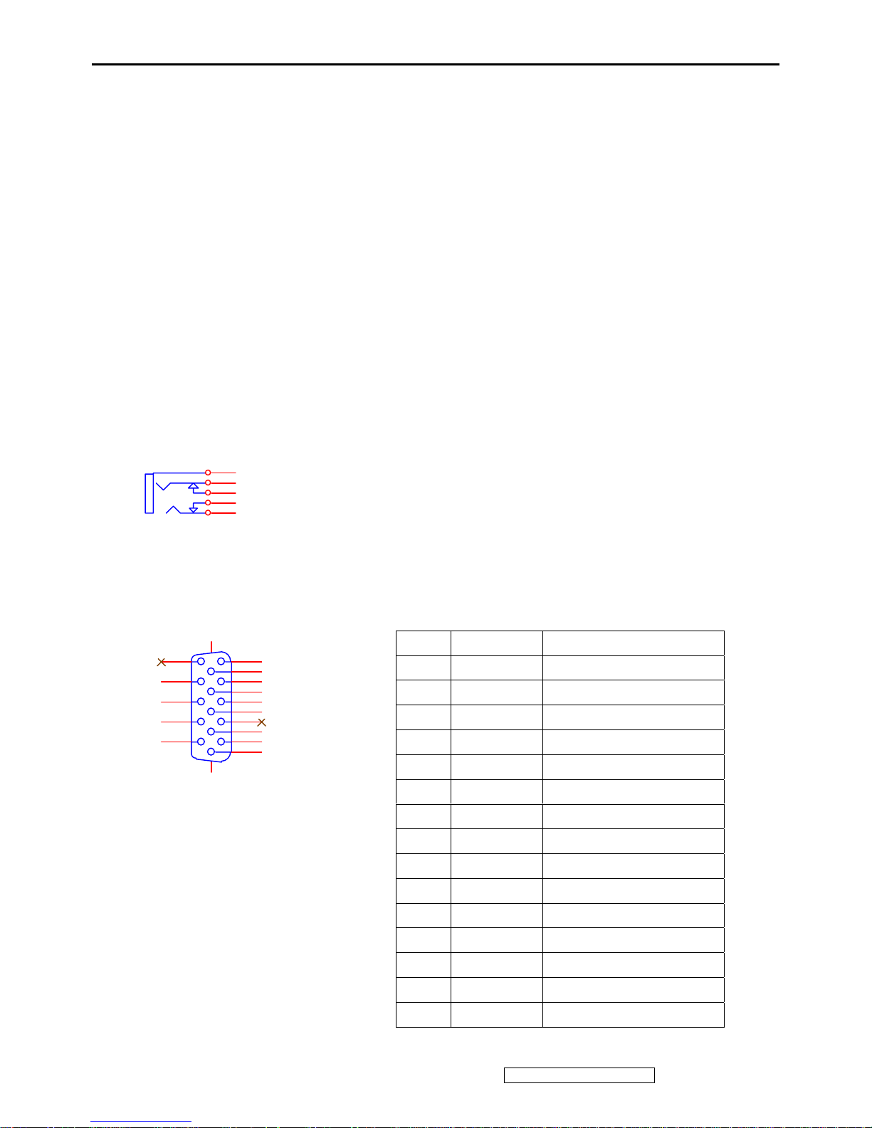
2.3 Video signal connector for analog input: 15P Mini D-Sub
CN1
VGA
1
6
2
7
3
8
4
9
5
11
12
13
14
15
10
1617
PIN MNEMONI SIGNAL
1 RV Red Video
2 GV Green Video
3 BV Blue Video
4 NC None
5 GND Ground(DDC return)
6 RG Red GND
7 GG Green GND
8 BG Blue GND
9 +5V +5V (for DDC)
10 SG Sync GND
11 NC None
12 SDA DDC Data
13 HS Horizontal Sync
14 VS Vertical Sync
15 SCL DDC Clock
Page 16

ViewSonic Corporation Confidential - Do Not Copy Q19wb-3
13
3. ELECTRICAL SPECIFICATIONS
3.1 Standard Testing conditions
Display Area 408.24(H) x 255.15(V) mm
Video Signal 0.7Vpp
Contrast Default
Brightness Default
Ambient 25 +/- 5 °C
Input AC230V+/-10%@50HZ
Warming up > 30 min
Display 1400 x 900@60HZ
3.2 POWER
3.2.1 Power supply
Input voltage 90~264Vac
Power frequency 47~63Hz
<1.2Arms@90Vac Input current
<0.7 Arms @264Vac
Inrush current 90A(Max) @ 264Vac(cold start)
Power consumption 40W(MAX)
3.2.2 Power Management
State Power Indicator
On <40Watts Green
Standby < 1Watts Amber
off <1Watts Dark
3.3 Acceptable timing
If the timing is within following specification, this LCD display can automatically function with a certain position.
Horizontal: Sync frequency: 31~81 KHz (Analog: 165MHz)
Vertical: Sync frequency: 50~75Hz
3.4 Signal level and input impedance
3.4.1 Video Signal level: 0.7Vp-p Video signal.
3.4.2 Sync Signal level
H/V Separate: TTL level
3.4.3 Input impedance
Analog video input: 75 ohm
Sync input: > 1 k ohm
Audio input: 10K ohm
4. SIGNAL CABLE: Signal cable with Mini D-Sub 15P connectors at both ends. Length: 1.8 meter.
Page 17

ViewSonic Corporation Confidential - Do Not Copy Q19wb-3
14
5. EDID data
5.1. Analog EDID: Analog EDID is stored in U6
HSD panel:
VIEWSONIC CORPORATION
EDID Version # 1, Revision # 3
DDCTest For: ViewSonic Q19wb-3
______________________________________________________________________
EDID Block 0, Bytes 0-127
128 BYTES OF EDID CODE:
0 1 2 3 4 5 6 7 8 9
________________________________________
0 | 00 FF FF FF FF FF FF 00 5A 63
10 | 1F 3E 01 01 01 01 01 10 01 03
20 | 08 29 1A 78 2E 9B B6 A4 53 4B
30 | 9D 24 14 4F 54 BF EF 80 95 00
40 | 95 0F 81 80 81 40 71 4F 01 01
50 | 01 01 01 01 9A 29 A0 D0 51 84
60 | 22 30 50 98 36 00 98 FF 10 00
70 | 00 1C 00 00 00 FF 00 51 48 5A
80 | 30 36 30 31 30 30 30 30 31 0A
90 | 00 00 00 FD 00 38 4B 1F 50 0E
100 | 00 0A 20 20 20 20 20 20 00 00
110 | 00 FC 00 51 31 39 77 62 2D 33
120 | 0A 20 20 20 20 20 00 98
______________________________________________________________________
(08-09) ID Manufacturer Name ________________ = VSC
(11-10) Product ID Code _____________________ = 3E1F
(12-15) Last 5 Digits of Serial Number ______ = Not Used
(16) Week of Manufacture _________________ = 01
(17) Year of Manufacture _________________ = 2006
(10-17) Complete Serial Number ______________ = See Descriptor Block
(18) EDID Version Number _________________ = 1
(19) EDID Revision Number ________________ = 3
(20) VIDEO INPUT DEFINITION:
Analog Signal
0.700, 0.300 (1.000 Vp-p)
Separate Syncs
(21) Maximum Horizontal Image Size ________________ = 410 mm
(22) Maximum Vertical Image Size __________________ = 260 mm
(23) Display Gamma ________________________________ = 2.20
(24) Power Management and Supported Feature(s):
Page 18

ViewSonic Corporation Confidential - Do Not Copy Q19wb-3
15
Active Off/Very Low Power, Standard Default Color Space,
Preferred Timing Mode
Display Type = R/G/B Color
(25-34) CHROMA INFO:
Red X - 0.643 Green X - 0.295 Blue X - 0.143 White X - 0.310
Red Y - 0.325 Green Y - 0.616 Blue Y - 0.081 White Y - 0.330
(35) ESTABLISHED TIMING I:
720 X 400 @ 70Hz (IBM,VGA)
640 X 480 @ 60Hz (IBM,VGA)
640 X 480 @ 67Hz (Apple,Mac II)
640 X 480 @ 72Hz (VESA)
640 X 480 @ 75Hz (VESA)
800 X 600 @ 56Hz (VESA)
800 X 600 @ 60Hz (VESA)
(36) ESTABLISHED TIMING II:
800 X 600 @ 72Hz (VESA)
800 X 600 @ 75Hz (VESA)
832 X 624 @ 75Hz (Apple,Mac II)
1024 X 768 @ 60Hz (VESA)
1024 X 768 @ 70Hz (VESA)
1024 X 768 @ 75Hz (VESA)
1280 X 1024 @ 75Hz (VESA)
(37) Manufacturer's Reserved Timing:
1152 X 870 @ 75Hz (Apple,Mac II)
(38-53) Standard Timing Identification:
1440 X 900 @60Hz
1440 X 900 @75Hz
1280 X 1024 @60Hz
1280 X 960 @60Hz
1152 X 864 @75Hz
Not Used
Not Used
Not Used
______________________________________________________________________
(54-71) Detailed Timing / Descriptor Block 1:
1440x900 Pixel Clock: 106.50 MHz
______________________________________________________________________
Horizontal Image Size: 408 mm Vertical Image Size: 255 mm
Refreshed Mode: Non-Interlaced Normal Display - No Stereo
Horizontal:
Active Time: 1440 pixels Blanking Time: 464 pixels
Page 19

ViewSonic Corporation Confidential - Do Not Copy Q19wb-3
16
Sync Offset: 80 pixels Sync Pulse Width: 152 pixels
Border: 0 pixels Frequency: 55.93 KHz
Vertical:
Active Time: 900 lines Blanking Time: 34 lines
Sync Offset: 3 lines Sync Pulse Width: 6 lines
Border: 0 lines Frequency: 59.89 Hz
Digital Separate, Horizontal Polarity (-) Vertical Polarity (+)
______________________________________________________________________
(72-89) Detailed Timing / Descriptor Block 2:
Monitor Serial Number:
QHZ060100001
______________________________________________________________________
(90-107) Detailed Timing / Descriptor Block 3:
Monitor Range Limits:
Min Vertical Freq - 56 Hz
Max Vertical Freq - 75 Hz
Min Horiz. Freq - 31 KHz
Max Horiz. Freq - 80 KHz
Pixel Clock - 140 MHz
Secondary GTF - Not Supported
______________________________________________________________________
(108-125) Detailed Timing / Descriptor Block 4:
Monitor Name:
Q19wb-3
(126) No Extension EDID Block(s)
(127) CheckSum OK
Page 20
ViewSonic Corporation Confidential - Do Not Copy Q19wb-3
17
6. THEORY OF OPERATION
This section describes the function of the LCD monitor per functional block.19” monitor includes MB
board (including audio board function inside), inverter board, (including adapter function inside) and button board.
6.1 MB BOARD
The MB board is a two-layer, sin gle-landed design with ground and ground planes provided.
The VGA cable is a sig nal cable that contains video signal, sync signal and DDC signal from PC VGA adapter
This system board consists of 3 functional areas : flat panel controller, Micro controller and audio controller.
6.1.1 Flat panel controller…… TSUM16AK-LF-1 (U4)
The heart of the system board is Mstar TSUM16AK-L F-1. The TSUM16AK-LF-1 is a graphics processing IC for
LCD monitor. It provides all key IC cont rol functions required for LCD panel. On-chip functions include a
high-speed triple-ADC , PLL, high sacling engine Micro processor and OSD controller ,manages other devices in
the system such as the keypad, the backlight, LED and audio general purpose input/output pins.
a) Clock Generation :
Crystal Input Clock (XTALI and XTAL). This is the input pair to an internal crystal oscillator andco rresponding
logic. A 14.318 MHz crystal is recommended.
b) Hardware Reset ( Pin 19 )
Hardware Reset signal is generated by TSUM16AK-LF-1 (U4/Pin 19).It assert a reset signal at least 1 ms.
Pin number Pin name Pin function
23 GPIO_P00/SAR1 Key-Menu
24 GPIO_P01/SAR2 Key-Sel/Auto
25 GPIO_P02/SAR3 Key-Power on/off
26 GPIO_P03 Key-Right
27 GPIO_P06 Key-Left
28 GPIO_P07 Key-Down(NC)
29 PWM0/GPIO_P26 Key-Up(NC)
30 GPIO_P13 LED-Green
31 GPIO_P14 LED-Orange
35 GPIO_P16/PWM2 Audio-MUTE(NC)
69 GPIO_P15/PWM0 Audio-Stby-Power
78 PWM2/GPIO_P24 Audio-Volume
21 PWM1/GPIO_P25 Backlight-adi
36 DDCD_SDA SDA-VGA (Debug)
37 DDCD_SCL SCL-VGA (Debug)
65 DDCA_SDA/RS232_TX SDA(Debug)
66 DDCA_SCL/RS232_RX SDA(Debug)
Page 21
ViewSonic Corporation Confidential - Do Not Copy Q19wb-3
18
c) Analog to Digital Converter
The TSUM16AK-LF-1 chip has three ADC's (analog-to-digital converters), one for each color (red, green
and blue) . The analog RGB signals are connected to TSUM16AK-LF-1 as described below
Pin Name Pin Number
Red + 59
Red - 58
Green + 56
Green - 55
Blue + 54
Blue - 53
d) OSD :
The TSUM16AK-LF-1 has a fully programmable, high-quality OSD controller. The on-chip static RAM(256
different fonts at size of 12X18) stores the cell map and the cell definitions.
e) Panel Power Sequencing (VDDCTRL_2, on_BACKLIGHT) ( Pin 74~20)
The TSUM16AK-LF-1 has two dedicated output s VDDCTRL_2 and on_backlight( Pin74 and Pin20) to
control LCD power sequencing once data and control signals a re stable.
f) Inverter Brightness control (PWM1) (Pin 21)
The TSUM16AK-LF-1 has one PWM output PWM1 (Pin21) to control Inverter Brightness
Range.
g) Panel LVDS interface (Pin105~114, Pin118~127)
The TSUM16AK-LF-1 driver interface is highly programmable. It supports LVDS port for panel.
6.1.2 Audio controller TDA7496L (AU1)
The TDA7496L is a 2 channel audio power amplifier capable of delivering 2W of continuous av erage power
to an 8 ohms with less than 3% (THD) from a 12 V power supply. TDA7496L can directly drive 8 ohms
speaker , Features of the TDA7496L include linear volume(pin6), Stand-by(pin11) and mute(pin12)
functions.
Audio line-in are feed into pin 4,9 of the TDA7496L. The output power is controlled by the DC voltage of
AQ1.
Page 22

ViewSonic Corporation Confidential - Do Not Copy Q19wb-3
19
6.2 Power Module
6.3
The power module includes a Inverter and Power regulator. The electrical specification described as followings:
Input Operation Input Voltage Range 90~260 Vac,47 ~63Hz
Rated Input Voltage 100~240 Vac,50/60Hz
Max Input AC Current < 2A
Brightness Voltage(Vadj) 0.3Vdc(Max) ~ 3.0Vdc(Min)
On/Off Voltage High(3.3Vdc)/Low(0Vdc)
Output Static Output Characteristics 12V/2.1A Output : 11.4Vdc ~ 15.1Vdc
5V/3.0A Output : 4.94Vdc ~ 5.46Vdc
6.2.2 Inverter output characteristics.
Rated Output Strike-on Voltage 1800~2000Vrms
Rated Output Voltage 680Vrms @ 6.5mArms
Rated Output Frequency 40~80KHz
OUTPUT
Rated Output Current 6~7mArms
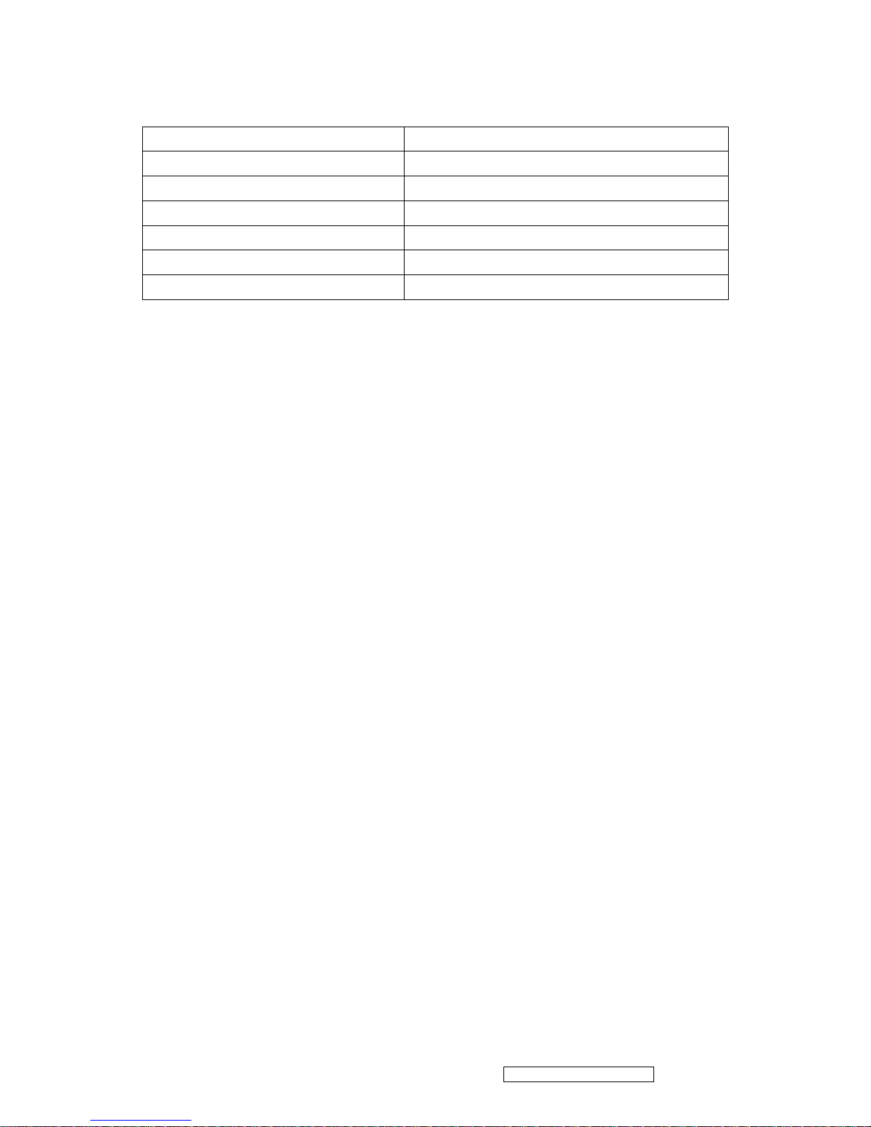
6.2.4 Power module of connector definition ;
CN101 ; Pin 1 & 2 ----> Vdc Output ( 12V +/- 5%)
Pin 3 & 4 -------> GND
Pin 5 & 6 -------> Vdc Output ( 5V +/- 5%)
Pin 7 -------------> Brightness Control Voltage
Pin 8 -------------> On /Off ( "High" set Lamp on )
CN202 ~ CN205 ; Pin 1 ---------> HV ( High Voltage for CCFL )
Pin 2 ---------> Return ( Low Voltage for CCFL )
Page 23

ViewSonic Corporation Confidential - Do Not Copy Q19wb-3
20
5. Adjustment Procedure
1. Function test
(1) Test equipment
Color video signal and pattern generator (or PC with SXGV resolution)
(2) Test condition
Before function testing and alignment, the unit must warm up for at least 30 minutes under the following
conditions:
1. Room temperature
2. With full-white screen , RGB , black pattern
3. with cycled display modes.
2. Test display modes
Item Timing Analog Digital
1 640 x 350 @ 70Hz, 31.5kHz Yes No
2 640 x 400 @ 70Hz, 31.5kHz Yes No
3 640 x 480 @ 60Hz, 31.5kHz Yes No
4 640 x 480 @ 67Hz, 35.0kHz Yes No
5 640 x 480 @ 72Hz, 37.9kHz Yes No
6 640 x 480 @ 75Hz, 37.5kHz Yes No
7 720 x 400 @ 70Hz, 31.5kHz Yes No
8 800 x 600 @ 56Hz, 35.1kHz Yes No
9 800 x 600 @ 60Hz, 37.9kHz Yes No
10 800 x 600 @ 75Hz, 46.9kHz Yes No
11 800 x 600 @ 72Hz, 48.1kHz Yes No
12 832 x 624 @ 75Hz, 49.7kHz Yes No
13 1024 x 768 @ 60Hz, 48.4kHz Yes No
14 1024 x 768 @ 70Hz, 56.5kHz Yes No
15 1024 x 768 @ 72Hz, 58.1kHz Yes No
16 1024 x 768 @ 75Hz, 60.0kHz Yes No
17 1152 x 864 @ 75Hz, 67.5kHz Yes No
18 1152 x 870 @ 75Hz, 68.7kHz Yes No
19 1280 x 1024 @ 60Hz, 63.4kHz Yes No
20 1280x 1024 @ 75Hz, 79.97kHz Yes No
21 1440x 900 @ 60Hz, 59.9kHz Yes No
22 1440x 900 @ 75Hz, 75kHz Yes No
Page 24

ViewSonic Corporation Confidential - Do Not Copy Q19wb-3
21
3. Test pattern
Item Test condition Pattern Specification Remark
1 Frequency & performance Cross-hatch pattern No noise is allowed, all colors must be clear Pattern 1
2 Monitor saturation 16-gray scale pattern 3 to 4 levels must be saturated when brightness and
contrast are set to 100%
Pattern 2
3 RGB color performance RGB color Check the color temperature of RGB signal color Pattern 3,
4, 5
4 Sub-pixel defect RGB color Check the sub-pixel defect Pattern 3,
4 , 5
5 Full white Full white Check the brightness and contrast ratio, and check
for bright pixel defects
Pattern 6
6 Full black Full black Pattern 7
7. 5-cycle pattern 5-cycle pattern Check the BU Pattern 8
8. 1-dot pattern 1-dot pattern Check the flicker Pattern 9
Pattern 1 Pattern2
Pattern 3 Pattern4
Page 25

ViewSonic Corporation Confidential - Do Not Copy Q19wb-3
22
Pattern 5 Pattern6
Pattern 7 Pattern 8
Pattern 9
Page 26

ViewSonic Corporation Confidential - Do Not Copy Q19wb-3
23
OSD Function Menu
A. When in Analog Input Mode
1. Main Menu
Press the [Menu] button to enter the Main Menu:
Press the
[<] button to immediately activate Brightness/Contrast menu. It should be
change to Contrast OSD by push button [<] or[>].
Press the [>] button to immediately activate Speaker Volume & the control
bar is adjustable by [<], [>] button.Mute or Speaker volume can be switched by press
[Menu] key when speaker volume OSD appear
Press the [AUTO] button to exit the Main Menu.
(1) Brightness /Contrast Page:
Press the [Menu] button to enter the Brightness/contrast adjustment page.
Press the
[AUTO] button to exit the page.
Press the
[<]button to highlight the previous item or the [>] button to highlight the next
item.
1) Brightness Item
Press the [Menu]button to enter the brightness adjustment page.
Press the
[>] button to increase the brightness.
Press the
[<] button to decrease the brightness.
Press the
[AUTO] button to exit the page.
2) Contrast Item
Press the [Menu]button to enter the Contrast adjustment page.
Press the
[>] button to increase the contrast.
Press the
[<] button to decrease the contrast.
Press the
[AUTO] button to exit the page.
(2) Image Control Page:
Press the [Menu] button to enter the Image Control Page.
Press the
[AUTO] button to exit the page.
Press the
[<]button to highlight the previous item or the [>] button to highlight the next
item.
1) Auto Adjustment Item
Press the [Menu]button to execute the auto adjustment function.
Page 27

ViewSonic Corporation Confidential - Do Not Copy Q19wb-3
24
Press the [AUTO] button to exit the page.
.
2) H. Position Item
Press the [Menu]button to enter the horizontal postion adjustment page.
Press the
[>] button to shift the image to the right.
Press the
[<] button to shift the image to the left.
Press the
[AUTO] button to exit the page.
3) V. Position Item
Press the [Menu]button to enter the vertical postion adjustment page.
Press the
[>] button to shift the image to the upward.
Press the
[<] button to shift the image to the downward.
Press the
[AUTO] button to exit the page.
4) Clock Item
Press the [Menu]button to enter the clock adjustment page.
Press
[>] & [<]Button to adjust the internal clock. Larger values make
the displayed image appear wider; smaller values make it appear compressed.
Press the
[AUTO] button to exit the page.
5) Phase Item
Press the [Menu] button to enter the phase adjustment page.
Press
[>] & [<] Button to Adjusts the internal clock’s time lag in order to
optimize the screen image.
Press the
[AUTO] button to exit the page.
6) Sharpness Item
Press the [Menu] button to enter the sharpness adjustment page.
Press
[>] Button to increase image sharpness.
Press
[<] Button to decrease image sharpness.
Press the
[AUTO] button to exit the page.
Page 28

ViewSonic Corporation Confidential - Do Not Copy Q19wb-3
25
(3) Color Page:
Press the [Menu] button to enter the color adjustment page.
Press the
[AUTO]button to exit the page.
Press the
[<]button to highlight the previous item or the [>] button to
highlight the next item.
1) 9300k Item
2) 6500K Item
3) 5400K Item
4) SRGB Item
Press the [Menu] button to select the currently highlighted item.
Press the
[AUTO] button to exit the currently highlighted item.
5) User Color Item
Press the [Menu] button to enter the user color page.
Press the
[AUTO] button to exit the page.
Red, Green, Blue Options:
Press the [Menu] button to enter the RGB adjustment page
Press the
[AUTO]button to exit the page.
Press the
[>] button to increase the selected color level.
Press the
[<]button to decrease the selected color level.
(4) OSD Control Page:
Press the [Menu] button to enter the OSD control page.
Press the
[AUTO] button to exit the page.
Press the
[<] button to highlight the previous item or the [>] button to
highlight the next item.
1) H.OSD Position Item
Press the [Menu] button to enter the H.OSD Position adjustment page.
Press
[>] Button to shift the OSD to the right.
Press
[<] Button to shift the OSD to the left.
Press the
[AUTO] button to exit the page.
Page 29

ViewSonic Corporation Confidential - Do Not Copy Q19wb-3
26
2) V.OSD Position Item
Press the [Menu] button to enter the V.OSD Position adjustment page.
Press
[>] Button to shift the image to the upward.
Press
[<] Button to shift the image to the downward.
Press the
[AUTO] button to exit the page.
3) OSD Time Out Item
Press the [Menu] button to enter the OSD time out adjustment page.
Press the
[>] button to increase the OSD time out.
Press the
[<] button to decrease the OSD time out.
Press the
[AUTO] button to exit the page.
(5) Other Page:
Press the [Menu] button to enter the OSD control page.
Press the
[AUTO] button to exit the page.
Press the
[<] button to highlight the previous item or the [>] button to
highlight the next item.
1) Language Item
Press the [Menu] button to enter the language selection page.
Press the
[AUTO] button to exit the page.
Press the
[<] button to highlight the previous item or the [>] button to highlight the
next item.
English, French… Option
Press the [Menu] button to select the language.
2) Speaker Volume Item
Press the [Menu] button to enter the speaker volume adjustment page.
Press
[>] Button to increase the volume.
Press
[<] Button to decrease the volume.
Press the
[AUTO] button to exit the page.
3) Information Item
Press the [Menu] button to enter the Information page.
Page 30

ViewSonic Corporation Confidential - Do Not Copy Q19wb-3
27
Press the [AUTO] button to exit the page.
Press the
[<] button to highlight the previous item or the [>] button to highlight the
next item.
ON,OFF select
Press the [Menu] button to select the ON/OFF.
(6) Reset Page:
Press the [Menu] button to enter the reset page.
Press the
[AUTO] button to exit the page.
Press the
[<] button to highlight the previous item or the [>] button to
highlight the next item.
YES,NO select
Press the [Menu] button to select the YES/NO.
(7) Exit Page:
Press the [Menu]/
[AUTO] button to exit the OSD Menu.
2. Other Menu:
This “shortcut” menu is directly accessible without bringing up the OSD.
(1) Brightness /Contrast Dialog
Press the
[<] button to enter the Brightness /Contrast Dialog.
Press the
[AUTO] button to exit the Brightness /Contrast Dialog.
Press the
[<] button to highlight the previous item or the [>] button to highlight the next
item.
Press the [Menu] button to enter the brightness/contrast adjustment page.
Press the
[>] button to increase the brightness/contrast.
Press the
[<] button to decrease the brightness/contrast.
(2)
Speaker volume/Mute Dialog
Press the
[>] button to enter the Speaker volume/Mute Dialog.
Press the
[AUTO] button to exit the Speaker volume/Mute Dialog.
Press the [Menu] button to switch the
Speaker volume and Mute page.
Page 31

ViewSonic Corporation Confidential - Do Not Copy Q19wb-3
28
Press the [>] button to increase the volume.
Press the
[<] button to decrease the volume.
B. Other Information
When the “No Signal” or “Out of Range” messages appear:
If no input signal is detected, the “No Signal” message will appear in the center of the screen.
If the V-Sync signal rate is greater than than 85Hz or it s resolution is greater than SXGA, the “Out
of Range” message will appear in the center of the screen.
Activating Factory Mode and Burn Mode:
While the device is in standby, press the
[AUTO] button, then press the power button to enter
Factory Mode. While Factory Mode is active, an additional menu page titled “F1”&”F2” will be
accessible. Press the [Menu] button to enter the Factory Menu page, then press the [Menu]
button to enter Burn Mode.
When Installing a New Main Board
1. Enter Factory Mode.
2. Use a PC or chrom to send a 32-tone gray scale signal to the monitor.
3. Select “Auto Color”
Page 32

ViewSonic Corporation Confidential - Do Not Copy Q19wb-3
29
Firmware update procedure :
When you received a received monitor , please check whether the firmware version. If not , please following procedure to
upgrade to the latest version .
1. Equipment needed :
- W9V-Q2
- PC ( Personal computer )
- LPT cable
- Fixture (LM5ISP)
- Firmware upgrade program
2. Connection :
To PC To Monitor
Page 33

ViewSonic Corporation Confidential - Do Not Copy Q19wb-3
30
Appendix A : How to install the software for ISP :
0. To setup ISP environment :
Hardware: PC or notebook, parallel(printer) cable, ISP tooling.
Software: If OS was Win2000 or WinXP , please install “PORT95NT.exe”
In order to ensure can execute ISP program, please set BIOS in PC or Notebook as Fig 0.0
Fig 0.0
0.1 Double-click the “ PORT95NT.exe” in Windows & install the program. , see Fig 0.1
Fig 0.1
Page 34

ViewSonic Corporation Confidential - Do Not Copy Q19wb-3
31
0.2 Keep on press “ Next “ 4 times to go through the installation processes, see Fig. 0.2
Fig. 0.2
0.3 Choose “ Typical “ then press “ Next “ , see Fig. 0.3
Fig. 0.3
Page 35

ViewSonic Corporation Confidential - Do Not Copy Q19wb-3
32
0.4 Keep on press “ Next “ 4 times to go through the installation processes, see Fig. 0.4
Fig. 0.4
0.5 Install completed , restart the PC or notebook. See Fig 0.5
Fig. 0.5
Page 36

ViewSonic Corporation Confidential - Do Not Copy Q19wb-3
33
Appendix B : How to use software to upgrade the BIOS :
1.1 Double-click the “ ISP_TOOL.exe” in Windows, see Fig 1.1
Fig. 1.1
1.2 It is the main meun of ISP_TOOL , see Fig 1.2
Fig. 1.2
Page 37

ViewSonic Corporation Confidential - Do Not Copy Q19wb-3
34
1.3 Single-click the “Connect” button to connect with MCU. The dialog of “O.K.” will appear in window, when the computer
has finished to connect with MCU, see Fig 1.3
Fig. 1.3
1.4 Single-click the “Read” button,you can select the file of BIOS. see Fig 1.4& Fig1.5
Fig. 1.4
Page 38

ViewSonic Corporation Confidential - Do Not Copy Q19wb-3
35
Fig. 1.5
1.5 When the file of BIOS has been selected ,you will see the dialog,see Fig1.6
Fig. 1.6
Page 39

ViewSonic Corporation Confidential - Do Not Copy Q19wb-3
36
Appendix C : Use ISP to program MCU
2.1 Single-click the “Run” button,you can program the MCU. .see Fig2.1
Fig. 2.1
2.2 If the program has been done,you will seen fig3.2. Now you must Single-click the “Dis Con” to disconnect with MCU.
Fig2.2.
Page 40

Q19wb-3 series de-assembling procedure
1. Move the monitor our from carton 2. Put the monitor on desk & face down
3. Loose the screws &Remove the HINGE COVER 4. Loose the screws & remove the stand
5. Loose the screws &Separate the BACK COVER 6. Remove the black tap e & AL-Foil
ViewSonic Corporation Confidential - Do Not Copy Q19wb-3
37
Page 41

7. Pull out the cables & Loose the screws &Separate the
speaker
8. Remove the AL-Foil
9.Remove the AL-Foil 10. Pull out the cables
11. Loose the screw 12.Tear off the yellow tape& Pull out the LVD cables
ViewSonic Corporation Confidential - Do Not Copy Q19wb-3
38
Page 42

13. Loose the bezel screw 14. Remove the bezel
15. Loose the BKT screw L/R 16. Move the BKT screw L/R
17. Remove the BEZEL BKT 18. Remove the GASKET
ViewSonic Corporation Confidential - Do Not Copy Q19wb-3
39
Page 43

19. Loose the BUTTON/B screw& Remove the BUTTON/B 20. Loose the IO NUT
21. Remove the POWER/B MYLAR 22. Loose the screw
23. Separate the M/B&P/B& GND PLATE 24.Separate the M/B&LVDS CABLE
ViewSonic Corporation Confidential - Do Not Copy Q19wb-3
40
Page 44

Q19wb-3 series packing method
1. Sticker on LCD protection film 2. Put the monitor into the PE or EPE bags
3. Put on the end-cap left / right 4. Put the monitor into carton
5. Put all accessories into carton 6. Seal the monitor
Face-up
Power cable & Audio cable
Base
VGA cable
MANUAL+CD
ViewSonic Corporation Confidential - Do Not Copy Q19wb-3
41
Page 45

ViewSonic Corporation Confidential - Do Not Copy Q19wb-3
42
6. Troubleshooting Flow Chart
1.No power
NO
No Power
Change Power Board
Check Power Module
Output CN101
Pin 5,6 = 5V?
Check Scalar Module
Output CN4
Pin 5,6 = 5V?
OK
Change Cable
From(Power module)CN101 to (Scalar/B)CN4
NO
OK
Check Power Button
From Scalar/B(CN8)
to Button/B(CON1)
NO
Check Cable
Open?
YES
Change Cable
NO
Change Switch or Button Board
Page 46

ViewSonic Corporation Confidential - Do Not Copy Q19wb-3
43
2.No Characters , Missing one color
Check R101 , 1.8V output
Check or Change Q5
Check R98 , 3.3V output
Check or Change U3
Check CN7 to Panel Signal Output
Check Inverter
From Power
board OK?
Change Power Board
Check X’Tal 14.318Mhz
Change X1
Check H,V SYNC?
Change U4
Check or Change Cable or Panel
Change VGA Cable
No Characters or Missing one color
Check CN4 5V Output
Change Power Board
NO
OK
NO
OK
NO
OK
NO
NO
OK
OK
OK
NO
NO
Page 47

ViewSonic Corporation Confidential - Do Not Copy Q19wb-3
44
3.No Audio
NO
OK
NO
OK
NO
No Audio
Check Input Signal AJ1
OK?
Check Input source or Change AJ1 U3
Check ACN1 to
Speaker OK?
Change Speaker or ACN1(Cable)
Check AU1(pin6)
Volume and AQ1 OK?
Change AQ1
Check
AU1(pin12)Mute,(pin11)
Stby
Change AU1 or AQ2 or AQ3
Page 48

ViewSonic Corporation Confidential - Do Not Copy Q19wb-3
45
7. Recommended Spare Parts List
Serial No. Prefix: QHZ Rev: 1a
Item ECR/ECN ViewSonic P/N Ref. P/N Location Universal number#
1
Accessories:
Power Cord - B 1.8M SP-035/10A A-PC-0106-0224 DM333181G97
2 Power Supply Board - EADP-45AF 90~240V B-00008124 AS05B520037
3 Main Board - L9F-A2 (W9ZA-L2 M16AK-LF-1) B-00008125 21L9F0MB0D3
4 Control Board (Button Board L0ZJ-A1) B-00008126 23L0ZJBB050
5 Hinge Cover - W9E-A1 C-00008150 EBW9E002010
6 Front Panel - W9V-Q2 C-00008151 34W9V0LB018
7 Cover - W9C-B1 C-00008152 25W9C0LC012
8 Base Assembly - L7C-A3 C-00008153 38L7C0BS003
9 Audio Cable - (ST,1.8M) CB-00004149 DD0L0TPC007
10 VGA Cable (15/15P,1.8M) CB-00008044 DD0L7WPC001
11 MB-LCD Cable LVDS(30P,140MM,LINKTEC) CB-00008048 DDM0TWLC001
12
Documentation
:
User's Guide DC-00008140 HGW9V002010
13 LCD Panel 19" HSD190MGW-A02 5ms E-00008051 AA90MGW1024
14 LCD Panel 19" HSD190MGW-A00 5ms E-00008072 AA90MGW1059 AUO
15 Speaker L9F(X05015N-002) 1.5Wx2 E-00008097 DN005015S08
16 Bracket - Left -HSD W9ZA-A1 HW-00008026 FBW9ZA11013
17 Bracket - Right -HSD W9ZA-A1 HW-00008027 FBW9ZA10017
18 Screw - F3.0*6.0-T(MC) HW-00008028 MF30060TJB2
19 Screw - M 4.0* 10-T(MC) HW-00008029 MS40100T138
20
Miscellaneous:
LCD Film W9V M-00008032 JXW9V001010
21 Generic Foam Set P-00001347 30833
22 Generic Box P-00002515 20653
23 PE Bag P-00004159 HAL0T002019
24 Craft Box P-00008150 HFW9V002019
25 Craft Foam - Right P-00008151 HBW9ZA04017
26 Craft Foam - Left P-00008152 HBW9ZA03011
27
Plastics:
Stand - W9C-A1 PL-00008035 26W9ZCSA006
Remark 1:
Above listed items are examples, supplier can expand the rows to add more necessary items.
Remark 2:
RECOMMENDED SPARE PARTS LIST (Q19wb-3)
Description
PC Board
Assembly:
Cables:
ViewSonic Model Number: VS11578
All revised RSPLs with newly added items or any change made should be highlighted and correlated with the ECN/ECR approved by ViewSonic
Corporation. This is to eliminate repeated cross checks of each item between this version and prior versions.
Cabinets:
Hardware:
Packing Material:
Electronic
Components:
Page 49

ViewSonic Model Number: VS11578
Rev: 1a
Serial No. Prefix: QHZ
Item ViewSonic P/N Ref. P/N Description Location Universal number# Q'ty
1
N/A 1W9VZQVS046 W9V-Q2 LCD MONITOR(Q19WB-3,USA)GP
2
B-00008125 21L9F0MB0D3 L9F-A2 M/B ASSY(W9ZA-L2,M16AK-LF-1) GP
1
3
N/A 31L9F0SS0C1 L9F-A2 M/B S/S ASSY(W9ZA-L2,M16AK-1)GP
1
4
N/A CC547X6MD03 CAP EC 4.7U50V(+-20%105C.5*11,5K)CXN GP
C40 1
5 N/A CC610X6MD01 CAP EC 10U 50V(+-20%.105C.5*11,5K)CXN GP
C32,C34,C45,C49,C5
3,C54,C58,C97
8
6 N/A CC710X4MD02 CAP EC100U25V(+-20%105C,6.3*11,5K)CXN GP C15 1
7 N/A CC733L3MD17 CAP EC DIP 330U16V(+-20%,105C,8*11)LXNGP
AC3,AC5,AC9,AC11,
C30,C31,C76
7
8
N/A DFTJ05FR037 CONN DIP PHONE JACK 5P FR(J303-1-A-G+)GP
AJ1 1
9
N/A DFDS15FR041 CONN D-SUB 15P 3R FR(P1.15,H12.55) GP
CN1 1
10
N/A DFDS15FR076 CONN D-SUB 15P 3R FR(P1.15,H12.55) GP
CN1 1
11
N/A DFHD08FR102 CONN DIP HEADER 8P 2R FR(P2.54,H5.0) GP
CN4 1
12
N/A DFHD30MR267 CONN DIP HEADER 30P 2R MR(P2.0,H4.0) GP
CN7 1
13
N/A DFHD04MR132 CONN DIP HEADER 4P 1R MR(P2.0,H4.1) GP
ACN1 1
14
N/A BG614318081 XTALDIP14.318MHZ(+-30PPM,70.C 49/S) GP
X1 1
15
N/A AL007496D02 IC(20P) TDA7496L(DIP) GP
AU1 1
16
N/A AL007496D29 IC(20P) UTC TDA7496LK(DIP) GP
AU1 1
17
N/A DFHD08FR021 CONN DIP HEADER 8P 1R FR(P1.0,H3.0)GP
CN8 1
18
B-00008126 23L0ZJBB050 L0ZJ-A1 BUTTON/B ASSY(FOR W9C-B1)GP
1
19
N/A DAL0ZJTB129 PCB(BUTTON) L0ZJ-A1(2L,126*9,REVB)ID3 GP
1
20
N/A BEYG0004ZA1 LED(SMD) Y/G(KPTB-1612NSGC) GP
LED1 1
21
N/A DEFC2879003 CABLE FFC(8P,287MM,ID3)W9C-B2 GP
CON1 1
22
N/A FCL0ZJ01010 METAL DOME SWITCH L0ZJ-A1(FCL0ZJ01,3A)GP
1
23
B-00008124 AS05B520037 ADP/INV EADP-45AF BF, 90~264V GP
1
24
C-00008151 24W9V0LB018 W9V-Q2 LCD BEZEL ASSY GP
1
25
N/A 34W9V0LB018 W9V-Q2 LCD BEZEL SUB ASSY GP
1
26
N/A 36W9C0PS003 W9C-B1 PCB SHIELD ASSY(N/DVI)NEW GP
1
27
N/A FCL7B001018 POWER BOARD MYLAR L7B(FCL7B001,REV3A)GP
1
28
N/A FCL7G001016 AL FOIL L7G(FCL7G001,REV3A)HAN GP
1
29
N/A FCM7T004014 AL FOIL M7T(FCM7T004,REV3A) GP
2
30
M-SCW-0824-0726 MF30080BBJ5 SCREW F3.0*8L,B,NI GP
2
31
N/A MF30060TJB2 SCREW F3.0*6.0-T(MC)GP
5
32
M-SCW-0824-6799 MM35080BBW2 SCREW M3.5*8-B (NI,WASHER)GP
1
33
N/A EBW9E003016 BEZEL BKT W9E-A1(EBW9E003,REV3A) GP
1
34
N/A MM30050B241 SCREW M3.0*5.0-B BLACK (NYLOK)GP
2
35
M-SCW-0824-6761 MM30030IBJ4 SCREW M3*3-I-NI GP
16
36
N/A MF20025IBJ8 SCREW F2*2.5-I(NI) GP
2
37
M-MS-0808-8986 MBLI1004018 IO NUT LI1(MBLI1004,REV3A)GP
2
38
N/A GBL9C003019 GASKET 7*7*0.6T L9C-B1(GBL9C003,R3A)GP
1
39
N/A GBL9C002012 GASKET 15*8*0.6T L9C-B1(GBL9C002,R3A)GP
1
40
N/A FBW9TB02013 GND PLATE-VGA-PANEL W9TB(FBW9TB02,R3A)GP
1
41
C-00008152 25W9C0LC012 W9C-B1 LCD COVER ASSY GP
1
42
N/A EAW9C002011 LCD COVER W9C-B1(EAW9C002,REV3A) GP
1
43
N/A FBW9ZA03011 HINGE BKT W9ZA(FBW9ZA03,REV3A)GP
1
44
PL-00008035 26W9ZCSA006 W9ZC-A1 STAND ASSY GP
1
45
N/A EAL7C004019 STAND L7C-A1(EAL7C004,REV3C)GP
1
46
N/A FBW9E003016 HINGE ASSY W9E-A1(FBW9E003,REV3A) GP
1
47
N/A DDL70LTH103 CABLE ASSY L70L STAND-HINGE(1P, REV1A)GP
1
48
HW-00008029 MS40100T138 SCREW M4.0*10-T(MC)GP
4
49
M-SCW-0824-0727 MF30080IBJ0 SCREW F3.0*8-I(NI)GP
2
50
M-SCW-0824-6761 MM30030IBJ4 SCREW M3*3-I-NI GP
1
51
N/A FBL7C006012 GND PLATE L7C-A1(FBL7C006,REV3A)GP
1
52
N/A 27W9C0CS003 W9C-B1 CHASSIS ASSY GP
1
53
C-00008150 EBW9E002010 HINGE COVER W9E-A1(EBW9E002,REV3A) GP
1
54
CB-00008048 DDM0TWLC001 CABLE MB-LCD(30P,100MM,LG,AU)M0TW GP
1
55
N/A DDM0TWLC010 CABLE LVDS(30P,100MM,LINKTEC,LG)M0TW GP
1
56
E-00008097 DN005015S08 SPEAK ASSY L9F(X05015N-002)1.5W*2 GP
1
57
N/A MM40130P000 SCREW M4.0*13-P(BLACK)GP
2
58
N/A MM40120FJB8 SCREW M4.0*12-F(BLACK)GP
2
59
N/A 2AW9V0PTU08 W9V-Q1 PANEL DEPENDENT KIT ASSY(HSD) GP
1
60
E-00008051 AA90MGW1024 LCD 19"HSD190MGW1-A02 5MS FOR VSC CON GP
1
61
N/A AZW9V0BU008 W9V-Q1 BIOS(HSD190MGW1-A02)TUM16AL 5MS
1
62
HW-00008026 FBW9ZA11013 LCD BKT-L-HSD W9ZA-A1(FBW9ZA11,REV3A)GP
1
63
N/A FBW9ZA10017 LCD BKT-R-HSD W9ZA-A1(FBW9ZA10,REV3A)GP
1
64
N/A 2AW9V0PTU16 W9V-Q2 PANEL DEPENDENT KIT ASSY(HSD) GP
1
65
N/A AA90MGW1041 LCD 19" HSD190MGW1-A00K(5MS)FOR VSC GP
1
66
N/A AZW9V0BU105 W9V-Q2 BIOS HSD(A00K)TSUM16AK-LF-1 5MS
1
67
HW-00008026 FBW9ZA11013 LCD BKT-L-HSD W9ZA-A1(FBW9ZA11,REV3A)GP
1
68
N/A FBW9ZA10017 LCD BKT-R-HSD W9ZA-A1(FBW9ZA10,REV3A)GP
1
69
N/A 2AW9V0PTU24 W9V-Q2 PANEL DEPENDENT KIT ASSY(HSD-K)GP
1
70
E-00008072 AA90MGW1059 LCD 19"HSD190MGW1-A00 5MS FOR VSC GP
1
71
N/A AZW9V0BU024 W9V-Q2 BIOS HSD(A00)TSUM16AK-LF-1 5MS
1
72
HW-00008026 FBW9ZA11013 LCD BKT-L-HSD W9ZA-A1(FBW9ZA11,REV3A)GP
1
73
N/A FBW9ZA10017 LCD BKT-R-HSD W9ZA-A1(FBW9ZA10,REV3A)GP
1
74
N/A 28W9V0PK011 W9V-Q2 PACKING ASSY GP
1
75
C-00008153 38L7C0BS003 L7C-A3 BASE SUB ASSY(BLACK)GP
1
76
CB-00008044 DD0L7WPC001 CABLE MB-VGA(15P,1.8M)L7E BLACK 5.5 GP
1
77
CB-00004149 DD0L0TPC007 CABLE AUDIO(ST,1.8M)BLACK L0T GP
1
78
P-00004159 HAL0T002019 PE BAG L0T(HAL0T002,REV3A)GP
1
BOM LIST (Q19wb-3)
ViewSonic Corporation Confidential - Do Not Copy Q19wb-3
46
Page 50

Item ViewSonic P/N Ref. P/N Description Location Universal number# Q'ty
79
P-00008151 HBW9ZA04017 END CAP-R W9ZA-A1(HBW9ZA04,REV3A) GP
1
80
P-00008152 HBW9ZA03011 END CAP-L W9ZA-A1(HBW9ZA03,REV3A) GP
1
81
M-LB-0813-0747 HCL7V004013 CORE LABEL(HCL7V004,REV3A)GP
1
82
M-LB-0813-0745 HCL7V002011 SERIAL LEBAL L7V(HCL7V002,REV3A) GP
1
83
M-LB-0813-1042 HCL7V019011 CARTON LABEL L7VC(HCL7V019,REV3B) GP
1
84
M-LB-0813-1043 HCL70021011 HI-POT LABEL L70L(HCL70021,REV3A)GP
1
85
N/A HCW9V001010 ID LABEL W9V-Q1(HCW9V001,R3A) GP
1
86
DC-00008140 HGW9V002010 MANUAL+CD W9V-Q2(HGW9V002,R3A) GP
1
87
P-00008150 HFW9V002019 CARTON W9V-Q2(HFW9V001,R3A) GP
1
88
N/A JXW9C001017 HANDLE UPPER W9C-B1(JXW9C001,REV3A)GP
1
89
N/A JXW9C002013 HANDLE DOWN W9C-B1(JXW9C002,REV3A)GP
1
90
N/A HFW9C004019 SPACE PLATE W9C-B(HFW9C004,R3A) GP
0.036
91
N/A HFW9C003012 SPACE PLATE W9C-A(HFW9C003,R3A) GP
0.025
92
A-PC-0106-0224 DM333181G97 PWR CORD B 1.8M SP-305/10A USA GP
1
93
M-00008032 JXW9V001010 LCD FILM W9V(JXW9V001,R3A)440*285 GP
1
ViewSonic Corporation Confidential - Do Not Copy Q19wb-3
47
Page 51

ViewSonic Corporation Confidential - Do Not Copy Q19wb-3
48
8. Exploded Diagram and Exploded Parts List
ViewSonic Model Number: VS11578
Rev: 1a
Serial No. Prefix: QHZ
Item ViewSonic P/N Ref. P/N Description Q'ty
1 N/A EAW9V002014 LCD BEZEL W9V-Q2 1
2 M-SCW-0824-6761 MM30030IBJ4 SCREW M3*3-I-NI 17
3 N/A EBW9V002015 BUTTON W9V-Q2 1
4 N/A EBW9C002012 LED LENS W9C-B1 1
5 N/A 23L0ZJBB050 L0ZJ-A1 BUTTON/B ASSY 1
6 N/A MF20025IBJ8 SCREW F2*2.5-I(NI) GP 2
7 N/A FBW9ZA10017 LCD BKT-R-HSD W9ZA-A1( 1
8 HW-00008026 FBW9ZA11013 LCD BKT-L-HSD W9ZA-A1 1
9 E-00008097 DN005015S08 SPEAK ASSY L9F)1.5W*2 1
10 E-00008072 AA90MGW1059 LCD 19"HSD190MGW1-A00 5MS 1
11 N/A EBW9E003016 BEZEL BKT W9E-A1 1
12 N/A FCL7B001018 POWER BOARD MYLAR L7B 1
13 B-00008124 AS05B520037 ADP/INV EADP-45AF BF, 90~264V 1
14 M-MS-0808-8986 MBLI1004018 IO NUT LI1 2
15 N/A 21L9F0MB0D3 L9F-A2 M/B ASSY 1
16 N/A MF30060TJB2 SCREW F3.0*6.0-T(MC)GP 5
17 M-SCW-0824-6799 MM35080BBW2 SCREW M3.5*8-B (NI,WASHER)GP 1
18 N/A FAW9C001015 PCB SHIELD W9C-B1 1
19 N/A FCL7TA01018 SHIELD ING MYLAR 1
20 N/A FCL7G001016 AL FOIL M7G 2
21 N/A FCM7T004014 AL FOIL M7T 1
22 N/A FBW9ZA03011 HINGE BKT 1
23 N/A EAW9C002011 LCD COVER W9C-B1 1
24 HW-00008029 MS40100T138 SCREW M4.0*10-T 4
25 N/A FBW9E003016 HINGE ASSY W9E-A1 1
26 N/A EAL7C004019 STAND L7C-A1 1
27 HW-00008029 MS40100T138 CABLE ASSY L70L STAND-HINGE 1
28 N/A FBL7C006012 GND PLATE L7C-A1 1
29 M-SCW-0824-0727 MF30080IBJ0 SCREW F3.0*8-I(NI)GP 2
30 N/A EAL7C005015 BASE L7C-A1 1
31 M-MS-0808-9251 GAL5V002013 RUBBER FOOT L5VC 4
32 C-00008150 EBW9E002010 HINGE COVER W9E-A1 1
33 M-SCW-0824-0726 MF30080BBJ5 SCREW F3.0*8L,B,NI GP 2
34 N/A MM40120FJB8 SCREW M4.0*12-F(BLACK)GP 2
35 N/A MM40130P000 SCREW M4.0*13-P(BLACK)GP 2
36 N/A MM30050B241 SCREW M3.0*5.0-B BLACK 2
37 CB-00008048 DDM0TWLC001 CABLE MB-LCD 1
38 N/A DEFC3309006 CABLE FFC(8P,287MM,ID3)W9C-B2 1
39 N/A GBL9C003019 GASKET 7*7*0.6T L9C-B1 2
EXPLODED PARTS LIST (Q19wb-3)
Page 52

ViewSonic Corporation Confidential - Do Not Copy Q19wb-3
49
SPK
SPK
POWER/B
Main Board
Button Board
&INV./B
TO PANEL
TO PANEL LVDS
CN4
ACN1
CON1
CN8
CN7
CN202
CN203
CN204
CN205
CN101
Page 53

ViewSonic Corporation Confidential - Do Not Copy Q19wb-3
50
Page 54

ViewSonic Model Number: VS11578
Rev: 1a
Item ViewSonic P/N Ref. P/N Location Q'ty
1 N/A
1W9VZQVS046 W9V-Q2 LCD MONITOR(Q19WB-3,USA)GP
1
2 C-00008153
38L7C0BS003 L7C-A3 BASE SUB ASSY(BLACK)GP
1
3 P-00008152
HBW9ZA03011 END CAP-L W9ZA-A1
1
4 P-00008151
HBW9ZA04017 END CAP-R W9ZA-A1
1
5 P-00008150
HFW9V002019 CARTON W9V-Q2
1
6 M-LB-0813-1042
HCL7V019011 CARTON LABEL L7VC
1
7 CB-00008044
DD0L7WPC001 CABLE MB-VGA(15P,1.8M)L7E BLACK 5.5
1
8 CB-00004149
DD0L0TPC007 CABLE AUDIO(ST,1.8M)BLACK L0T GP
1
9 A-PC-0106-0224
DM333181G97 POWER CORD SP-30+IS-14 3P 1.8M(USA)B
1
10 P-00004159
HAL0T002019 PE BAG L0T
1
11 N/A
HGW9V001013 MANUAL+CD W9V-Q1
1
12 M-00008032
JXW9V001010 LCD FILM W9V
1
13 M-LB-0813-1043
HCL70021011 HI-POT LABEL L70L
1
14 N/A
HCW9V001010 ID LABEL W9V-Q1
1
15 M-LB-0813-0745
HCL7V002011 SERIAL LEBAL L7V
1
PACKING PART LIST (Q19wb-3)
ViewSonic Corporation Confidential - Do Not Copy Q19wb-3
51
Page 55

ViewSonic Corporation Confidential - Do Not Copy Q19wb-3
52
9. Block Diagram
LVB0P
ON/OFF
CE#
ADJ
VDDP
DDCROM_SCL
LED_ORANGE
LVA0M
VGA
SEL
LC
GIN-
HSYNC0
H-SYNC
PWM1
LVA1M
POWER BOARD
+1.8V
DDC-SCL
LED_GRN
RST
+3.3V
AVDD_PLL
LVB3M
LCD VDD
SWCHING
SDO
LVDS Interface
LVB2M
AVDD_DVI
LVACKM
GPIO_P25
LC
ON BACKLITE
MENU
BIN-
BGND
(24LC16)
XOUT
(SST25VF010)
RIN+
RGND
BIN+
14.318MHz
P00
ON/OFF
LCD-TFT Module
LVB1M
Inverter
G+
GPIO_P23
SDI
SOGIN
DDCROM_SDA
RIN-
VDDC
LVA3M
P13
LVB0M
LVACKP
P07
Q5
VCC3.3
V-SYNC
SOG
POWER
SDA
LVBCKM
P14
SDI
LVB2P
LC
U3
PWM0
LVBCKP
P02
VCTRL
LC
(TSUM16AK-LF-1)
VCC3.3
AVDD_ADC
RESET
LC
DDCA_SCL
VCC3.3
SW BOARD
Scaler
BRIGHTNESS ADJ
LVB1P
LVA0P
DDCA_SDA
+12V
P01
SCL
SCK
SCK
B+
VCC3.3
LVB3P
GIN+
+5V
(AP1117ELA)
P26
CE#
LVA1P
XIN
U5
R+
VDDCTRL_2
LEFT
DDC-SDA
LVA2M
SDO
LC
VSYNC0
VCC1.8
RIGHT
VCC3.3
AVDD_MPLL
VCTRL
ADJ
GPIO_P12
GGND
LVA2PU6LVA3P
CLK+
CLK-
CLK+
CLK-
CN1
System Block Diagram
Page 56

ViewSonic Corporation Confidential - Do Not Copy
53
10. Schematic Diagrams
Model
Title
Date Rev:
ViewSonic Corporation
VGA & DVI Input
RED+IN GREEN+IN BLUE+IN
IN-H IN-V VGA_SCL_OVGA_SDA_O
IN-V
RED+IN
VSYNC
BLUE-IN
GREEN+IN
BLUE+IN
GREEN-IN
RED-IN
IN-V
GREEN-IN
GREEN+IN
IN-H
VGA_SCL_O
BLUE+IN
DDC-SDA
RED-IN
VGA_SDA_O
DSUB_5V_O
DDC-SCL
RED+IN
RX2+RX2-
BLUE-IN
RX1+RX1-
SDA-DDDC
RX0-
SCL-DDDC
RXC+ RXC-
SCL-DDDC
SDA-DDDC
RX0+
HSYNC
IN-H
DDCD_SCL
DDCD_SDA
RX2RX2+
RX1RX1+
RX0+
RX0-
RXC+
RXC-
DSUB_5V
VCC3.3
DDC_VCC DDC_VCC
VCC3.3
VCC3.3
DVI_5V
DDC_VCC
DVI_5VVCC5V
DDC_VCC
VCC3.3
SOGIN 5
GREEN+ 5
RED- 5
BLUE+ 5
VSYNC 5
BLUE- 5
RED+ 5
GREEN- 5
DDCA_SCL 5
DDCA_SDA 5
DDCD_SCL 5
DDCD_SDA 5
R- 5
R+ 5
G- 5
B- 5
B+ 5
CLK+ 5
CLK- 5
G+ 5
HPD_Ctrl 5
HSYNC 5
C88
0.1uF/6/NC
D13
Z5.6/NC
2 1
C7 0.01uF/6
R25 100/6
R19 10/6
D2
DAN217K/NC
12
3
R2 100/6
C12
33pF/6
D7
Z5.6/NC
2 1
C10 0.047uF/6
R4 100/6/1%
R107 10K/6/NC
C6 0.047uF/6
C93
0.1uF/6/NC
C5
NC
R3
75/6/1%
R104
4.7K/6/NC
D11
DAN217K/NC
12
3
R17
2.2K/6
C3 0.047uF/6
D15
DAN217K/NC
12
3
R12 100/6/1%
R6
75/6/1%
R106 10K/6/NC
R30 10/6
U7 24C02
A0
1
A1
2
A2
3
GND4SDA
5
SCL
6
WP
7
VCC
8
C2
NC
R7 100/6/1%
R1 56/6/1%
C96
0.1uF/6/NC
R5 56/6/1%
D17
DAN217K/NC
12
3
D3
DAN217K/NC
12
3
L5 100/6
D8
DAN217K/NC
12
3
R14
2.2K/6
CN3
DVI-I
RX2-
1
RX2+
2
GND
3
RX4-
4
RX4+
5
SCL
6
SDA
7
VS
8
RX1-
9
RX1+
10
GND
11
RX3-
12
RX3+
13
5V
14
GND
15
HP
16
RX0-
17
RX0+
18
GND
19
RX5-
20
RX5+
21
GND
22
RXC+
23
RXC-
24
26
25
R117 220/6/NC
C1 0.047uF/6
D14
DAN217K/NC
12
3
Q13
PMBS3904/NC
C
B
E
C90
0.1uF/6/NC
R20
10K/6
R28 10/6
D32
BAT54C-GS08
R10 56/6/1%
D5
Z5.6/NC
2 1
C4 0.047uF/6
R118 220/6/NC
R24 100/6
CN1
VGA
1
6
2
7
3
8
4
9
5
11
12
13
14
15
10
1617
D16
DAN217K/NC
12
3
R29 10/6
R13 1K/6
R8 100/6
R15 100/6
D10
DAN217K/NC
12
3
L2 CX000300112
C89
0.1uF/6/NC
R16 1K/6
R18 10/6
R119 220/6/NC
R22 10/6
C95
0.1uF/6/NC
C86
0.1uF/6/NC
R11
75/6/1%
D12
Z5.6/NC
2 1
R111
0/6/NC
C13
0.1uF/6NC
R23 10/6
C101
0.1uF/6
D6
Z5.6/NC
2 1
R9 470/6
D1
DAN217K/NC
12
3
R120 220/6/NC
L4 CX000300112
C11
33pF/6
D9
DAN217K/NC
12
3
D4
Z5.6/NC
2 1
R27 10/6
C92
0.1uF/6/NC
C87
0.1uF/6/NC
L1 CX000300112
L3 0/ 6
C8 0.047uF/6
C91
0.1uF/6/NC
C9
NC
C94
0.1uF/6/NC
R26 10K/6
R21
10K/6
Q19wb-3
Page 57

ViewSonic Corporation Confidential - Do Not Copy
54
Model
Title
Date Rev:
ViewSonic Corporation
SCALER
MENU_OLEFT_O UP_O DOWN_OSEL_OPWR_ORIGHT_O
LEFT
MENU_O
UP
RIGHT_O
UP_O
PWR_O
LED_R
LEFT_O
SEL_O
LED_R_O
LED_R_G
LED_G
MENU
RIGHT
SEL
DOWN_O
PWR
DOWN
PWR
UP
SEL
RIGHT
MENU
LED_G
DOWN
LED_R
LEFT
MENU_O
SEL_O
PWR_O
RIGHT_O
LEFT_O
LED_R_O
LED_R_G
WP
WP
VCC1.8
VCC3.3
VDDC
AVDD
VCC3.3 VDDP
VCC3.3 VDVI
VCC3.3 VPLL
VMPLLVCC3.3
VCC3.3 VCC3.3 VCC3.3 VCC3.3 VCC3.3 VCC3.3 VCC3.3
VCC3.3
VCC3.3
VCC3.3
VCC3.3
VCC3.3
VMPLL VDDPVDVI
VCC3.3
VDDCVPLL
VCC5V
AVDD
VCC3.3
AVDD
5V
on_BACKLIGHT 6
VSYNC4
VCTRL 6
CLK-4
LVA3M 7
DDCD_SCL4
LVB2M 7
GREEN+4
HPD_Ctrl 4
RED+4
DDCA_SCL4
G-4
GREEN-4
LVA2M 7
LVA3P 7
LVA2P 7
LVB0P 7
R-4
LVB0M 7
SOGIN4
LVA1M 7
B-4
LVBCKP 7
G+4
LVB1M 7
LVA0P 7
LVB3M 7
STBY 8
LVB2P 7
adj_BACKLIGHT 6
HSYNC4
BLUE-4
LVB3P 7
LVA1P 7
VOLUME 8
LVA0M 7
RED-4
LVB1P 7
B+4
DDCD_SDA4
MUTE 8
BLUE+4
R+4
LVACKM 7
DDCA_SDA4
VDDCTRL_2 7
LVBCKM 7
LVACKP 7
CLK+4
TO BUTTON BOARD
2006/03/13 ADD
Add WP Control Avoid data losing.
FB3
CX201209813
C47
0.1uF/6
R71
4.7K/6
R70 4.7K/6
C51
0.1uF/6
R108 100/6
C48
0.1uF/6
R68
33K/6
+
C58
10uF/50V
L11 1K/6/1%
1 2
C52
0.1uF/6
R51
10K/6
R60 82K/6
C42
0.1uF/6
C650.1uF/6
R56 NC
C43
0.1uF/6
R74 100/6
R64
33K/6
C50
0.1uF/6
Q7
PMBS3906
C61
0.1uF/6
C97
10uF/50V
C630.1uF/6
R57
68K/6
+
C45
10uF/50V
U6 2 4C16
A0
1
A1
2
A2
3
GND4SDA
5
SCL
6
WP
7
VCC
8
L15 1K/6/1%
1 2
+
C49
10uF/50V
R62
10K/6
R63
33K/6
CN8
7101-E08N
1
2
3
4
6
8
7
5
C46
0.1uF/6
D26
DAN217K/NC
12
3
X1
14.318MHZ
L12 1K/6/1%
1 2
R66
33K/6
D25
DAN217K/NC
12
3
FB5
CX201209813
R59
10K/6
L17 100/6/1%
1 2
C39
0.1uF/6
C55
0.1uF/6
L18 330/6/1%
1 2
R105
10K/6
C41
0.1uF/6
U5
SST25VF512A
CE#
1
SDO
2
WP#
3
VSS4SDI
5
SCK
6
HOLD#
7
VDD
8
R67
33K/6
R103 NC
R65
33K/6
R54
10K/6
L16 1K/6/1%
1 2
C670.1uF/6
+
C40
4.7uF/50V
R75 100/6
CN5
JWT-A2001WV2-04/NC
1
2
3
4
C37
0.1uF/6
C44
0.1uF/6
L13 1K/6/1%
1 2
C100 0.1uF/6
R73
10K/6
C56 22pF/6
D31
DAN217K/NC
12
3
R55 NC
C36
0.1uF/6
C620.1uF/6
L10 1K/6/1%
1 2
+
C34
10uF/50V
FB1
CX201209813
CN6
4501-10-10P-R/NC
1
2
3
4
5
6
7
8
9
10
FB2
CX201209813
R109
10K/6
R58
10K/6
FB4
CX201209813
Q6
PMBS3906
U4
TSUM16AK-LF-1
RIN0P
59
GIN0P
56
SOGIN0
57
BIN0P
54
RIN0N
58
GIN0N
55
BIN0N
53
HSYNC0
63
VSYNC0
64
REXT
51
REFP
62
REFM
61
SDO
70
SCK
72
SCZ
71
SDI
73
GPIO_P27/PWM1
79
PWM1/GPIO_P25
21
LVACKM
108
XIN
32
XOUT
33
LVA2P
109
LVA2M
110
LVA1P
111
LVA1M
112
LVA0P
113
LVA0M
114
LVB3P
118
LVB3M
119
LVBCKP
120
LVBCKM
121
LVB2P
122
LVB2M
123
LVB1P
124
LVB1M
125
LVB0P
126
LVB0M
127
LVACKP
107
LVA3M
106
LVA3P
105
GND41GND
47
RX2P
39
RX2N
40
RX1P
42
RX1N
43
AVDD_DVI
44
RX0P
45
RX0N
46
RXCKP
48
RXCKN
49
GND38GND96GND
116
VDDP
67
VDDC
12
MODE[1]
104
MODE[0]
102
VCTRL
11
VDDP
14
VDD_OTP
68
DDCA_SDA
65
DDCA_SCL
66
DDCD_SDA
36
DDCD_SCL
37
PWM0/GPIO_P26
29
AVDD_DVI
50
VDDC
97
GPIO_P15
69
PWM2/GPIO_P24
78
GPIO_P12
20
GPIO_P17/SAR0
22
GPIO_P00/SAR1
23
GPIO_P01/SAR2
24
GPIO_P06
27
GPIO_P07
28
GPIO_P13
30
GPIO_P14
31
GPIO_P16
35
DDCROM_SDA
76
DDCROM_SCL
77
RST
19
NC
100
NC
101
NC
98
NC
99
NC
93
NC
94
NC
91
NC
92
NC
89
NC
90
NC
9
NC
10
NC
15
NC
16
NC
17
NC
18
NC
2
NC
3
NC
5
NC
6
NC
7
NC
8
NC
128
NC
1
NC
80
NC
81
NC
88
NC
87
NC
86
NC
85
NC
84
NC
83
NC
82
GPIO_P02/SAR3
25
GPIO_P03
26
GPIO_P22
75
GPIO_P23
74
AVDD_PLL
52
AVDD_MPLL34AVDD_MPLL
4
VDDP95VDDP
103
VDDP
115
VDDC
117
AVDD_ADC
60
GND
13
R61
10K/6
C35
0.1uF/6
C60 0.1uF/6
C98
1uF/8
R52
10K/6
C57 22pF/6
+
C54
10uF/50V
C640.1uF/6
FB6
CX201209813
C59
0.1uF/6
C680.1uF/6
C53
10uF/50V
R110
0/6/NC
R69
33K/6
D27
DAN217K/NC
12
3
C660.1uF/6
D30
DAN217K/NC
12
3
C38
0.1uF/6
D29
DAN217K/NC
12
3
L14 1K/6/1%
1 2
D28
DAN217K/NC
12
3
R72
10K/6
R53 390/6/1%
Q19wb-3
Page 58

ViewSonic Corporation Confidential - Do Not Copy
55
Model
Title
Date Rev:
ViewSonic Corporation
POWER
VCC3.3
VCC12
VCC3.3 VCC3.3
VCC3.3
VCC3.3
VCC5V
VCC5V
VCC1.8
5V
DSUB_5V DVI_5V
on_BACKLIGHT 5
adj_BACKLIGHT 5
VCTRL 5
0.8A Max
C14
0.1uF/6
Q4
PMBS3904
31
2
L9
CX121A50006/1206
+
C31
330uF/16V
CN4
4
5 6
1 2
3
87
D22
BAT54C-GS08
R100 0/6
+
C30
330uF/16V
U3-A
AP1117ELA/TO252/NC
ADJ/GND
1
VOUT
2
VIN
3
OUT
4
R50
100/6/1%
C99
0.1uF/NC
D21
ML25PT
Q2
PMBS3904
31
2
R36 1K/6C18
1uF/8
+
C32
10uF/50V
R47
330/6/1%
R46
200/6/1%
Q5
CHT2907APT
C
B
E
R43 2K/6
U3
AP1117ELA/TO223
ADJ/GND
1
VOUT
2
VIN
3
OUT
4
C24
1uF/8/NC
D24
LL1N4148PT
R48
47/6
Q8
CHT2907APT
C
B
E
R31
10K/6
R32
10K/6
R38
1K/6
C15
100uF/25V
D23
LL1N4148PT
R96
0/6/NC
R41 0/6
R49
2K/6
R95
0/6
Q19wb-3
Page 59

ViewSonic Corporation Confidential - Do Not Copy
56
Model
Title
Date Rev:
ViewSonic Corporation
PANEL
RXO1-LVB1M
RXO0-LVB0M RXO0+ LVB0P
RXO1+ LVB1PLCDVCC
RXO3+ LVB3P
RXE2-LVA2M
LVBCKM RXOC-
LCDVCC
GND
RXE1-LVA1M
GND
RXE1+ LVA1P
LCDVCC
GND
RXE2+ LVA2P
RXE3-LVA3M
RXO3-LVB3M
RXE0+ LVA0P
RXE3+ LVA3P
POL
RXOC+ L VBCKP
LCDVCC
LVB2M RXO2-
LVACKM RXEC-
LVB2PRXO2+
RXEC+ LVACKP
RXE0-LVA0M
GND
LVB3M
LVBCKP
LVB0M
LVB1P
LVBCKM
LVB0P
LVB3P
LVB1M
LVB2M
LVB2P
LVA3P
LVA3M
LVACKP
LVA2P
LVACKM
LVA2M
LVA1M
LVA1P
LVA0P
LVA0M
LCDVCC
15GND
15GND
LCDVCC
GND
GND
VCC3.3
LCDVCC
VCC5V
VDDCTRL_2 5
LVA0P 5
LVBCKP 5
LVB2P 5
LVACKP 5
LVA1P 5
LVA2M5
LVB2M5
LVACKM5
LVA3P 5
LVBCKM5
LVB0P 5
LVB3M5
LVA0M5
LVB3P 5
LVA1M5
LVA2P 5
LVB0M5
LVB1M5
LVB1P 5
LVA3M5
LVBCKP5
LVA0P5
LVB2P5
LVA2M5
LVACKP5
LVA1P5
LVBCKM5
LVACKM5
LVA3P5
LVB2M5
LVB3M5
LVB0P5
LVA0M5
LVA1M5
LVB3P5
LVA2P5
LVA3M5
LVB1M5
LVB0M5
LVB1P5
E
1
S
1
2
3
C
B
2
G
3
D
2006/03/14 ADD FFC FPE Connector
R86
10K/6
R102
0/6
12
R85
82K/6
Q12
SN7002E/NC
3
2
1
1
H2
MTH276D126
2
3
4
5 6
7
8
9
C76
330uF/16V
R77
0/8
R81
10K/6
12
Q9 AO3415L
3
2
1
R83
3.6K/NC
CN7
1
1
3
3
5
5
7
7
9
9
11
11
13
13
15
15
17
17
19
19
21
21
23
23
25
25
27
27
29
29
2
2
4
4
6
6
8
8
10
10
12
12
14
14
16
16
18
18
20
20
22
22
24
24
26
26
28
28
30
30
CN9
FFC 30PIN PH=1.0 (MS240430)/NC
1
1
2
2
3
3
4
4
6
6
8
8
10
10
12
12
14
14
16
16
18
18
20
20
22
22
24
24
26
26
28
28
30
30
7
7
9
9
11
11
13
13
15
15
17
17
19
19
21
21
23
23
25
25
27
27
29
29
5
5
313132
32
C73
2200pF/6
12
1
H3
MTH276D126
2
3
4
5 6
7
8
9
1
H1
MTH276D126
2
3
4
5 6
7
8
9
C75
0.1uF/6
12
R99
0/6/NC
R80
82K/6
C74
2200pF/6
1 2
Q11
CHDTC144EUPT
2
31
R87
1.2K/6/NC
Q19wb-3
Page 60

ViewSonic Corporation Confidential - Do Not Copy
57
Model
Title
Date Rev:
ViewSonic Corporation
AUDIO
LIN_PC
RIN_PC
VOLU
VOLU
L_LINE
R_LINE
SPKOUTL
Z0415
SPKOUTR
Z0416
GNDAGND
AGND
GND
AGND
AGND
AGND
AGND
AGND AGND
AGND
AGND
+12V_A
+12V_A
+12V_A
+12V_A
+12V_A
VCC12
VCC3.3
VCC3.3
AGND
AGND
VOLUME5
MUTE5
STBY5
PC
AUDIO-IN
AR14 1K/6
AL6 CX201209813
AR6 100/6
AR13
10K/6
AL7 CX201209813
AC1
1uF/8
ACN1
1
2
3
4
AC11
330uF/16V
AQ3
PMBS3906
R91
20K/6
AL3 CX201209813
1 2
AC2
0.1uF/6
AR2 10K/6
AJ1
2
3
4
5
1
AR9 CX201209813
AC8
220pF/6
AU1
TDA7496L
INL
4
INR
9
VAROUT_L
5
VOLUME
6
VAROUR_R
7
OUTL
17
OUTR
14
MUTE
12
STBY
11
SVR
10
GND
13
VS15VS
16
GND1GND2GND3GND19GND20GND
18
R92
20K/6
AR12 10K/6
AR10 10K/6
AL4 CX201209813
1 2
AC7
220pF/6
AC4 0.47uF/6
AR8 CX201209813
AQ2
PMBS3906
R94
10K/6
AC3
330uF/16V
AC10
0.1uF/6
AC9
330uF/16V
AR15 1K/6
AL5
CX201209813
AR11
10K/6
AR1 10K/6
AR7 100/6
AC5
330uF/16V
R93
10K/6
AC6 0.47uF/6
AL1 CX201209813
AQ1
PMBS3904
2
31
AL2 CX201209813
AR5 2K/6
AR4 4.7K/6
AR3 1K/6
Q19wb-3
Page 61

ViewSonic Corporation Confidential - Do Not Copy
58
Model
Title
Date Rev:
ViewSonic Corporation
AC to DC ADAPTOR
Q19wb-3
Page 62

ViewSonic Corporation Confidential - Do Not Copy
59
Model
Title
Date Rev:
ViewSonic Corporation
AC to DC ADAPTOR
Q19wb-3
Page 63

ViewSonic Corporation Confidential - Do Not Copy
60
Model
Title
Date Rev:
ViewSonic Corporation
Metal Dome Button Board
MENU
SEL
PWR
LEFT
AMBER
RIGHT
GREEN
Orange / Blue : KPTB-1612SEKPBAC
Orange / Green : KPTB-1612NSGC
SW3 SW METALDOME
SW4 SW METALDOME
SW5 SW METALDOME
CON1
PH=1.0mm 8Pin/NC
1
2
3
4
6
8
7
5
9 10
BLUE
AMBER
3
12
4
LED1 KPTB-1612
SW1 SW METALDOME
SW2 SW METALDOME
Q19wb-3
Page 64

ViewSonic Corporation Confidential - Do Not Copy Q19wb-3
61
11. PCB Layout Diagrams
Page 65

ViewSonic Corporation Confidential - Do Not Copy
62
Q19wb-3
Page 66

ViewSonic Corporation Confidential - Do Not Copy
63
Q19wb-3
Page 67

ViewSonic Corporation Confidential - Do Not Copy
64
Q19wb-3
Page 68

ViewSonic Corporation Confidential - Do Not Copy
65
Q19wb-3
Page 69

ViewSonic Corporation Confidential - Do Not Copy
66
Q19wb-3
Page 70

ViewSonic Corporation Confidential - Do Not Copy Q19wb-3
67
* Reader’s Response*
Dear Readers:
Thank you in advance for your feedback on our Service Manual, which allows continuous improvement
of our products. We would appreciate your completion of the Assessment Matrix below, for return to
ViewSonic Corporation.
Assessment
A. What do you think about the content of this Service Manual?
Unit Excellent Good Fair Bad
1. Precautions and Safety Notices
2. Specification
3. Front Panel Function Control Description
4. Circuit Description
5. Adjustment Procedure
6. Troubleshooting Flow Chart
7. Recommended Spare Parts List
8. Exploded Diagram and Exploded Parts List
9. Block Diagrams
10. Schematic Diagrams
11.PCB Layout Diagrams
B. Are you satisfied with this Service Manual?
Item Excellent Good Fair Bad
1. Service Manual Content
2. Service Manual Layout
3. The form and listing
C. Do you have any other opinions or suggestions regarding this service manual?
Reader’s basic dada:
Name:
Title:
Company:
Add:
Tel:
Fax:
E-mail:
After completing this form, please return it to ViewSonic Quality Assurance in the USA at facsimile
1-909-839-7943. You may also e-mail any suggestions to the Director, Quality Systems & Processes
(marc.maupin@viewsonic.com)
 Loading...