


Service Manual
ViewSonic VA912-4
VA912b-4
Model No. VS10867
19” Color TFT LCD Display
ViewSonic
(VA912/b-4_SM Rev. 1a Nov. 2005)
381 Brea Canyon Road, Walnut, California 91789 USA - (800) 888-8583
Copyright
Copyright
reproduced, transmitted, transcribed, stored in a retrieval system, or translated into any language or
computer language, in any form or by any means, electronic, mechanical, magnetic, optical, chemical,
manual or otherwise, without the prior written permission of ViewSonic Corporation.
Disclaimer
ViewSonic makes no representations or warranties, either expressed or implied, with respect to the
contents hereof and specifically disclaims any warranty of merchantability or fitness for any particular
purpose. Further, ViewSonic reserves the right to revise this publication and to make changes from time
to time in the contents hereof without obligation of ViewSonic to notify any person of such revision or
changes.
Trademarks
Optiquest is a registered trademark of ViewSonic Corporation.
ViewSonic is a registered trademark of ViewSonic Corporation.
All other trademarks used within this document are the property of their respective owners.
2005 by ViewSonic Corporation. All rights reserved. No part of this publication may be
¤
Revision History
ECR Number
1a
11/09/05
Initial Release
Description of Changes
EditorRevision SM Editing Date
G. Han
ViewSonic Corporation Confidential
i
-
Do Not Copy VA912/b-4

TABLE OF CONTENTS
1. Precautions and Safety Notices
2. Specification
3. Front Panel Function Control Description
4. Circuit Description
5. Adjustment Procedure
6. Troubleshooting Flow Chart
7. Recommended Spare Parts List
8. Exploded Diagram and Exploded Parts List
9. Block Diagram
10. Schematic Diagrams
11. PCB Layout Diagrams
1
3
11
13
24
34
37
43
47
48
53
ViewSonic Corporation Confidential
ii
-
Do Not Copy VA912/b-4

1. Precautions and Safety Notices
1. Appropriate Operation
(1) Turn off the product before cleaning.
(2) Use only a dry soft cloth when cleaning the LCD panel surface.
(3) Use a soft cloth soaked with mild detergent to clean the display housing.
(4) Use only a high quality, safety approved AC/DC power cord.
(5) Disconnect the power plug from the AC outlet if the product will not be used for a long period of time.
(6) If smoke, abnormal noise, or strange odor is present, immediately switch the LCD display off.
(7) Do not touch the LCD panel surface with sharp or hard objects.
(8) Do not place heavy objects on the LCD display, video cable, or power cord.
(9) Do not use abrasive cleaners, waxes or solvents for your cleaning.
(10) Do not operate the product under the following conditions:
- Extremely hot, cold or humid environment.
- Areas containing excessive dust and dirt.
- Near any appliance generating a strong magnetic field.
- In direct sunlight.
2. Caution
No modification of any circuit should be attempted. Service work should only be performed after you are thoroughly familiar
with all of the following safety checks and servicing guidelines.
3. Safety Check
Care should be taken while servicing this LCD display. Because of the high voltage used in the inverter circuit, the voltage is
exposed in such areas as the associated transformer circuits.
4. LCD Module Handling Precautions
4.1 Handling Precautions
(1) Since front polarizer is easily damaged, pay attention not to scratch it.
(2) Be sure to turn off power supply when connecting or disconnecting input connector.
(3) Wipe off water drops immediately. Long contact with water may cause discoloration or spots.
(4) When the panel surface is soiled, wipe it with absorbent cotton or other soft cloth.
(5) Since the panel is made of glass, it may break or crack if dropped or bumped on hard surface.
(6) Since CMOS LSI is used in this module, take care of static electricity and ensure human earth when handling.
(7) Do not open or modify the Module Assembly.
(8) Do not press the reflector sheet at the back of the module in any direction.
(9) In the event that a Module must be put back into the packing container slot after it was taken out of the
container, do not press the center of the CCFL Reflector edge. Instead, press at the far ends of the
CFL Reflector edge softly. Otherwise the TFT Module may be damaged.
(10) At the insertion or removal of the Signal Interface Connector, be sure not to rotate or tilt the Interface
Connector of the TFT Module.
ViewSonic Corporation Confidential
1
-
Do Not Copy VA912/b-4

(11) After installation of the TFT Module into an enclosure (LCD monitor housing, for example), do not twist or
bend the TFT Module even momentarily. When designing the enclosure, it should be taken into consideration
that no bending/twisting forces may be applied to the TFT Module from outside. Otherwise the TFT Module
may be damaged.
(12) The cold cathode fluorescent lamp in the LCD contains a small amount of mercury. Please follow local
ordinances or regulations for disposal.
(13) The LCD module contains a small amount of materials having no flammability grade. The LCD module
should be supplied with power that complies with the requirements of Limited Power Source
(IEC60950 or UL1950), or an exemption should be applied for.
(14) The LCD module is designed so that the CCFL in it is supplied by a Limited Current Circuit (IEC60950
or UL1950). Do not connect the CCFL to a Hazardous Voltage Circuit.
ViewSonic Corporation Confidential
2
-
Do Not Copy VA912/b-4
2. Specification
1 PRODUCT DEFINITION AND SPECIFICATION
VSA
VSAP
VSE
VSCN
Region
(M)
Product Name
(A)/(S)/(K)
(E)/(U)
VA912/b-4 / VA912-4U
(G)
Model Number VS10867
English, French, German, Italian, Spanish,
OSD Languages
Finnish, Japanese, Traditional Chinese,
Simplified Chinese
TFT LCD Panel and Model # Vendor : HSD, Model # : 190ME13 A02
Scalar Model # : RTD 2523
Input Signal Analog / Digital
Sync Compatibility Separate
Audio 1W x 2
a. Refer to Appendix D
Power Cable
b. U model: (2 power cables are required)
1. Schuko CEE7-7 Type Plug
2. Separate 3-prong BS 1363 Type Plug
Analog Cable (1.8 m, color : black), with PC
YES
2001 and Hot Plug Detect &DDC
Audio Cable (1.8m, Color: black) with PC
YES
2001
DVI Cable(1.8m, color: black) with PC 2001
ViewSonic CD Wizard
ViewSonic Quick Start Guide
Screen Protector Mylar
Warranty Sticker NO NO NO
Warranty Card NO NO NO
Carton Sticker NO NO NO
PE bag of Carton NO NO NO
YES YES No YES
Arabic, English, Finnish, Spanish, German,
Italian, Swedish, Polish, Korean, Portuguese,
Russian, French, Simplified Chinese, Traditional
Chinese, Hungary, Czech, Turkish
YES YES YES YES
YES
YES
YES
YES
ViewSonic Corporation Confidential
3
-
Do Not Copy VA912/b-4

This product specification is divided into the following categories:
4-1 General Specification 4-11 Environmental
4-2 Video Interface 4-12 Manuals and Documents
4-3 Power Supply 4-13 Regulatory and Safety
4-4 Electrical Requirement 4-14 Video Communications
4-5 Front Panel Control and Indicators 4-15 Coding Assignment
4-6 Audio Interface 4-16 Reliability
4-7 TFT LCD Panel 4-17 Mass Production Release
4-8 Image Performance 4-18 ECR / ECN
4-9 Mechanical 4-19 Service
4-10 Packaging
ViewSonic Corporation Confidential
4
-
Do Not Copy VA912/b-4
GENERAL specification
Test Resolution & Frequency 1280x1024 @ 60Hz
Test Image Size Full Size
Contrast and Brightness Controls
Factory Default:
Contrast = 70%, Brightness = 100%
VIDEO INTERFACE
Analog Input Connector DB-15 (Analog), refer the appendix A
Digital Input Connector DVI-I (digital)
Default Input Connector Defaults to the first detected input
Equal to twice the weight of the monitor for
Video Cable Strain Relief
five minutes
Video Cable Connector DB-15 Pin out Compliant DDC 2B
1. Video RGB (Analog)
Video Signals
2. DVI (Digital)
Separate
Video Impedance 75 Ohms (Analog)
Maximum PC Video Signal 950 mV with no damage to monitor
Maximum Mac Video Signal 1250 mV with no damage to monitor
Sync Signals LVDS
DDC 2B Compliant with Revision 1.3
Sync Compatibility Separate Sync
Shall be compatible with all PC type
Video Compatibility
computers, Macintosh computers, and after
market video cards
640 x 350*, 640 x 480, 720 x 400* (640 x
400*), 800 x 600, 832 x 624, 1024 x 768,
1152 x 870, 1280 x 720, 1280 x 960, 1280 x
Resolution Compatibility
1024
* The image vertical size might not be full screen.
But the image vertical position should be at the center.
Exclusions Not compatible with interlaced video
ViewSonic Corporation Confidential
5
-
Do Not Copy VA912/b-4
POWER SUPPLY
Power Supply (Adapter) FSP043-2PI01
Input Voltage Range 90 TO 264 VAC
Input Frequency Range 47 TO 63 HERTZ
Short Circuit Protection Output can be shorted without damage
Over Current Protection 5.13 A typical at 18.1 VDC
Leakage Current 0.25mA (Max) at 264VAC / 50Hz
EFFICIENCY 80 % typical at 115VAC Full Load
Fuse Internal and not user replaceable
Power Dissipation 65 Watts
Max Input AC Current 1.8Arms @ 90VAC,
INRUSH CURRENT (COLD START) 100 A @ 240VAC , 50Hz
Shall start and function properly when under
Power Supply Cold Start
Power Supply Transient Immunity
Power Supply Line Surge Immunity
Power Supply Missing Cycle Immunity
Power Supply Acoustics
full load, with all combinations of input
voltage, input frequency, and operating
temperature
Shall be able to withstand an EN61000-4-4
±2KV transient test with no damage
Shall be able to withstand ±2KV (L-L) and
±2.3KV (L-PE) with no damage
Shall be able to function properly, without
reset or visible screen artifacts, when ½
cycle of AC power is randomly missing at
nominal input
The power supply shall not produce audible
noise that would be detectable by the user.
Audible shall defined to be in compliance
with ISO 7779 (DIN EN27779:1991) Noise
measurements of machines acoustics.
Power Switch noise shall not be considered
Separate 3-prong NEMA 5-15P type plug.
US Type Power Cable
Length = 1.8m. Connects to display.
Color = Black
Schuko CEE7-7 type plug.
European Type Power Cable
Length = 1.8m, Connects to display.
Color = Black
Separate 3-prong type plug.
CCC Type Power Cable
Length = 1.8m. Connects to display.
Color = Black
ViewSonic Corporation Confidential
6
-
Do Not Copy VA912/b-4
Separate 2-prong NEMA 1-15P type plug.
PSE Type Power Cable
Length = 1.8m. Connects to display.
Color = Black
Power Saving Operation(Method) VESA DPMS Signaling
ON Mode < 40W (max) / 36 W (typ)
Power Consumption
ACTIVE OFF < 1 W
Recovery Time ON MODE = N/A, ACTIVE OFF < 5 SEC
ELECTRICAL REQUIREMENT
Horizontal / Vertical Frequency
Horizontal Frequency 30 – 82 KHZ
Vertical Refresh Rate 50 – 85* HZ.
Maximum Pixel Clock 135 MHz
Sync Polarity Independent of sync polarity.
Timing Table
Item Timing Analog Digital
1 640 x 350 @ 70Hz, 31.5kHz Yes Yes
2 640 x 400 @ 60Hz, 31.5kHz Yes Yes
3 640 x 400 @ 70Hz, 31.5kHz Yes Yes
4 640 x 480 @ 60Hz, 31.5kHz Yes Yes
5 640 x 480 @ 67Hz, 35.0kHz Yes Yes
6 640 x 480 @ 72Hz, 37.9kHz Yes Yes
7 640 x 480 @ 75Hz, 37.5kHz Yes Yes
8 640 x 480 @ 85Hz, 43.27kHz Yes Yes
9 720 x 400 @ 70Hz, 31.5kHz Yes Yes
10 800 x 600 @ 56Hz, 35.1kHz Yes Yes
11 800 x 600 @ 60Hz, 37.9kHz Yes Yes
12 800 x 600 @ 75Hz, 46.9kHz Yes Yes
13 800 x 600 @ 72Hz, 48.1kHz Yes Yes
14 800 x 600 @ 85Hz, 53.7kHz Yes Yes
15 832 x 624 @ 75Hz, 49.7kHz Yes Yes
16 1024 x 768 @ 60Hz, 48.4kHz Yes Yes
17 1024 x 768 @ 70Hz, 56.5kHz Yes Yes
18 1024 x 768 @ 72Hz, 58.1kHz Yes Yes
19 1024 x 768 @ 75Hz, 60.0kHz Yes Yes
20 1024 x 768 @ 85Hz, 68.67kHz Yes Yes
21 1152 x 870 @ 75Hz, 68.7kHz Yes Yes
ViewSonic Corporation Confidential
7
-
Do Not Copy VA912/b-4

22 1280 x 1024 @ 60Hz, 63.4kHz Yes Yes
23 1280 x 1024 @ 75Hz, 79.97kHz Yes Yes
24 1280x 720 @ 60Hz, 45kHz (HDTV) Yes Yes
Primary Presets
1280x1024 @ 60Hz
User Presets
Number of User Presets (recognized timings) Available: 10 presets total in FIFO
configuration
Changing Modes
● Maximum Mode Change Blank Time for image stability : 3 seconds (Max), excluding
“Auto Adjust” time
● Under DOS mode (640 x 350, 720 x 400 & 640 x 400), there is no “Auto Adjust”
feature.
● The monitor needs to do “Auto Adjust” the first time a new mode is detected but except
the DOS mode 640 x 350, 720 x 400 & 640 x 400.(see section “0-Touch™ Function
Actions”)
● While running Change Mode, Auto Adjust or Memory Recall, the image shall blank
FRONT PANEL CONTROLS AND INDICATORS
Front Panel Hardware Controls
Power Switch (Front Head) Power Control, soft Power Switch.
Power LED (Front Head) Green – ON
Orange – Active Off
Dark = Soft Power Switch OFF
Front Panel Controls (Head)
[;X] [ 1 ] [▲] [▼] [ 2 ] [
]
] Power
[
[ 1 ] Button 1
[ 2 ] Button 2
[▲] Up arrow button
[▼] Down arrow button
[; X]
MUTE
Note: Power Button, Button 1 and Button 2
and Mute Button must be one-shot logic
operation. (i.e. there should be no cycling)
Reaction Time OSD must fully appear within 0.5s after
pushing Button 1
ViewSonic Corporation Confidential
8
-
Do Not Copy VA912/b-4
Panel Source Identify
(1) ID label - The panel code “T” for HSD panel should be shown on the lower right side
of ID label. (See Figure 2)
(2) UPC label - The panel code “T” for HSD panel should be shown on the lower right
side of UPC label. (See Figure 3)
Panel Characteristics:
Model number HSD 190ME13-A02
Type TN type with LVDS interface
Active Size 376.32 (H) x 301.056 (V)
Pixel Arrangement RGB Vertical Stripe
Pixel Pitch 0.294 mm
GLASS TREATMENT Anti Glare (Hard coating 3H)
# OF BACKLIGHTS 4 CCFL direct light
BACKLIGHT LIFE 40,000 Hours (min)
Luminance (Center) –
Condition:
250 cd/m2 (Typ after 30 minute warm up)
200 cd/m2 (Min after 30 minute warm up)
CT = 6500K, Contrast = Max,
Brightness = Max
U = 80% (typ), 75% (Min).
Brightness Uniformity (9 Points)
U = Min Luminance in 5 points / Max
Luminance in 5 points
Contrast Ratio 600 (typ), 450 (min)
Color Depth 16 million colors (6 bit + 2 bit FRC)
Viewing Angle (Horizontal)
VIEWING ANGLE (VERTICAL)
Response Time
@ CR>10
Typical: 140
Minimum: 120
@ CR>10
Typical: 130
Minimum: 110
8ms (Tr= 2 ms, Tf = 6 ms) (typ)
@ CR>5
Typical: 160
Minimum: 140
@ CR>5
Typical: 150
Minimum: 130
10%-90% @ Ta=25°C
20 ms (Tr= 7 ms, Tf = 13 ms) (max)
Panel Defects Please see Panel Quality Specifications.
ViewSonic Corporation Confidential
9
-
Do Not Copy VA912/b-4
MECHANICAL
Dimension (Desktop)
Width 437 mm (17.2 inch)
Height 419 mm (16.5 inch)
Depth 216 mm (8.5 inch)
Monitor Weight 4.7 Kg/ 10.4 lbs
Ergonomics
Tilt Up ≧ 20 º to 18°
Tilt Down ≦ -5 º to -3°
Vibration Test
● Vibration Frequency : 2 – 200 Hz
● Acceleration : 1.14 G RMS
● Sweep Time : 1 oct. / min
*Refer to Figure 1
● Test Time : 60 min per axis, total 3 axis / 6 main face
● Vibration Test Data shall be submitted for approval to ViewSonic before Mass
Production
Drop Test (100G)
● Weak Corner : 76.2 cm
● Six Faces : 76.2 cm
● 3 Edges Radiating From Weak Corner : 76.2 cm
● Drop Test Data shall be submitted for approval to ViewSonic before Mass Production
ENVIRONMENTAL
● Operating Temperature : 5°C to +35°C
● Storage Temperature : -20°C to +55°C
● Operating Relative Humidity : 20% to 80% RH Non-Condensing
● Storage Relative Humidity : 20% to 85% RH Non-Condensing
● Operating Altitude : 0 to +3,000 meters
● Storage Altitude : 0 to +12,000 meters
ViewSonic Corporation Confidential
10
-
Do Not Copy VA912/b-4
3. Front Panel Function Control Description
ViewSonic Corporation Confidential
11
-
Do Not Copy VA912/b-4

ViewSonic VA921-4/VA921b-4/VA912-4U
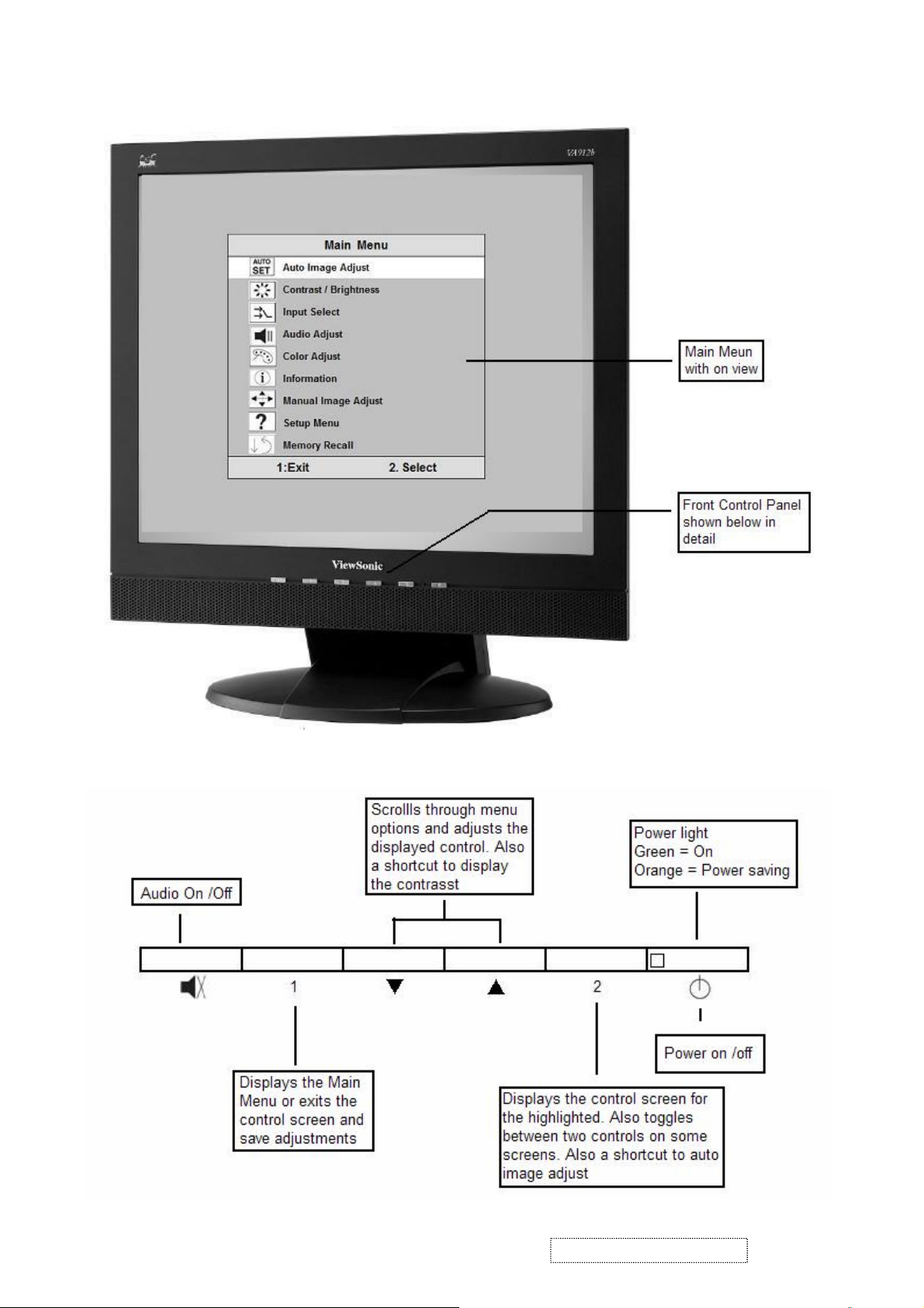
Main Menu Controls
Adjust the menu items shown below by using the up and down buttons.
A. Auto Image Adjust automatically sizes, centers, and fine tunes the video signal to eliminate waviness and distortion.
Press the [2] button to obtain a sharper image.
NOTE: Auto Image Adjust works with most common video cards. If this function does not work on your LCD
display, then lower the video refresh rate to 60 Hz and set the resolution to its pre-set value.
B. Contrast adjusts the difference between the image background (black level) and the foreground (white level).
C. Brightness adjusts the lamps current to control the screen brightness.
D. Input adjusts the Analogue or the Digital input source
E. Audio Adjust the volume increase or decrease and mute function
F. Color Adjust
adjust red (R), green (G), and blue (B). The factory setting for this product is 6500K (6500° Kelvin).
9300K — Adds blue to the screen image for cooler white (used in most office settings with fluorescent lighting).
5400K — Adds red to the screen image for warmer white and richer red.
Custom User Color — Individual adjustments for red, green, and blue.
1 To select color (R, G or B) press button [2].
2 To adjust selected color, press or .
3 When you are finished making all color adjustments, press button [1] twice.
G. Information displays the timing mode (video signal input) coming from the graphics card in your computer. See your
graphic card’s user guide for instructions on changing the resolution and refresh rate (vertical frequency). VESA 1280
x 1024 @ 60 Hz (recommended) means that the resolution is 1280 x 1024 and the refresh rate is 60 Hertz.
H. Manual Image Adjust
H. Size (Horizontal Size) adjusts the width of the screen image.
NOTE: Vertical size is automatic with your LCD display.
H./V. Position adjusts horizontal and vertical position of the screen image. You can toggle between Horizontal and
Vertical by pressing button [2]. Horizontal moves the screen image to the left or to the right. Vertical moves the screen
image up and down.
Fine Tune sharpens focus by aligning the illuminated text and/or graphic characters.
Sharpness adjusts the clarity and focus of the screen image.
Setup Menu controls are explained below:
Language allows you to choose the language used in the menus and control screens.
Resolution Notice displays the recommended resolution for this LCD display.
Enable allows the Resolution Notice to appear on-screen.
Disable will not allow the Resolution Notice to appear on-screen.
OSD Timeout sets the length of time an on-screen display screen is displayed. For example, with a“15 second”
I. OSD Position allows you to move the on-screen display menus and control screens.
J. Memory Recall
Timing Mode listed in this user guide.
provides several color options: preset color temperatures and Custom User Color which allows you to
controls are explained below:
setting, if a control is not pushed within 15 seconds, the display OSD disappears.
returns adjustments to the original factory settings if the display is operating in a factory Preset
ViewSonic Corporation Confidential
12
-
Do Not Copy VA912/b-4
4. Circuit Description
1. Outline
1.1 Power On/Off, up arrow- button, down arrow button, (1) MENU button, (2) Enter button, Mute button on
the front panel.
1.2 D-sub 15pin connector, DVI-D connector, audio line-in receptacle, and AC-IN are located on the back side
of the cabinet.
1.3 OSD menu includes the following function;
Auto Image Adjust (only active under analog input)
Contrast/Brightness
Input Select
Audio Adjust
Color Adjust
Information
Manual Image Adjust
Setup Menu
Memory Recall
1.4 Contrast and Brightness can be directly controlled with UP / DOWN key.
1.5 Audio volume can be controlled with up key and down key when Audio Adjust menu is active.
Pushing Mute key can disable audio output.
1.6
2. CONNECTORS
2.1 AC inlet : CEE22 typed connector
2.2 Audio : Line-in,
CN9
Line-in receptacle
(Line-in receptacle is green)
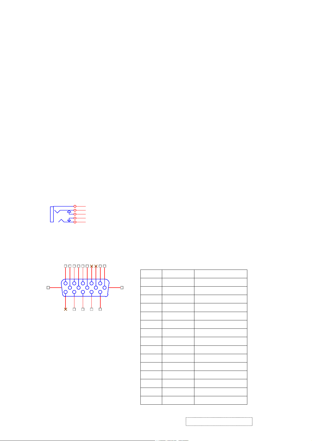
2.3 Video signal connector for analog input: 15P Mini D-Sub
16
1
11
1
5
4
3
2
6
2
7
3
8
4
9
12
13
14
5
15
10
CN6
DB15HD
17
PIN MNEMONI SIGNAL
1 RV Red Video
2 GV Green Video
3 BV Blue Video
4 NC None
5 GND Ground (DDC return)
6 RG Red GND
7 GG Green GND
8 BG Blue GND
9 +5V +5V (for DDC)
10 SG Sync GND
11 NC None
12 SDA DDC Data
13 HS Horizontal Sync
14 VS Vertical Sync
15 SCL DDC Clock
ViewSonic Corporation Confidential
13
-
Do Not Copy VA912/b-4
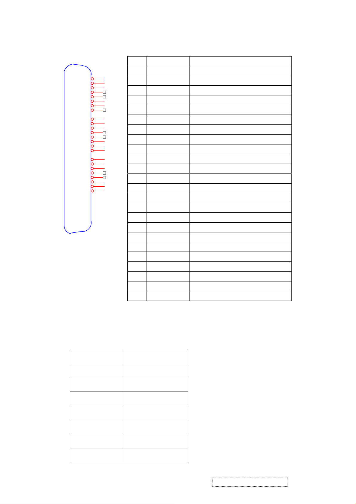
Video signal connector for digital input: 24pin DVI-D connector
2.4
CN9
Pin No. Signal Name Description
1 RX2- TMDS negative differential input, channel 2
1
RX2-
RX2+
GND
RX4-
RX4+
SCL
SDA
VS
RX1-
RX1+
GND
RX3-
RX3+
5V
GND
HP
RX0-
RX0+
GND
RX5-
RX5+
GND
RXC+
RXC-
2
3
4
5
6
7
8
9
10
11
12
13
14
15
16
17
18
19
20
21
22
23
24
2 RX2+ TMDS positive differential input, channel 2
3 GND Logic Ground
4 RX4- Reserved. No connection
5 RX4+ Reserved. No connection
6 SCL DDC2B Clock
7 SDA DDC2B Data
8 VS Reserved. No connection
9 RX1- TMDS negative differential input, channel 1
10 RX1+ TMDS positive differential input, channel 1
11 GND Logic Ground
12 RX3- Reserved. No connection
13 RX3+ Reserved. No connection
14 +5V Power
15 GND Logic Ground
16 HP SENSE Pin, Pull High
17 RX0- TMDS negative differential input, channel 0
DVI-D
18 RX0+ TMDS positive differential input, channel 0
19 GND Logic Ground
20 RX5- Reserved. No connection
21 RX5+ Reserved. No connection
22 GND Logic Ground
23 RXC+ TMDS positive differential input, reference clock
24 RXC- TMDS negative differential input, reference clock
3. ELECTRICAL SPECIFICATIONS
3.1 Standard conditions
Display Area
Video Signal
Contrast
Brightness
Ambient
Input
Warming up
Display
376.32 x 301.056 mm
0.7Vpp
Default
Default
20 +/- 5 °C
AC
> 30 min
1280 x 1024
ViewSonic Corporation Confidential
14
-
Do Not Copy VA912/b-4
3.2 POWER
3.2.1 Power supply
Input voltage 100~240Vac
Power frequency 50~60Hz
Input current
Inrush current
Power consumption 36W(typical);40Watts(Max)
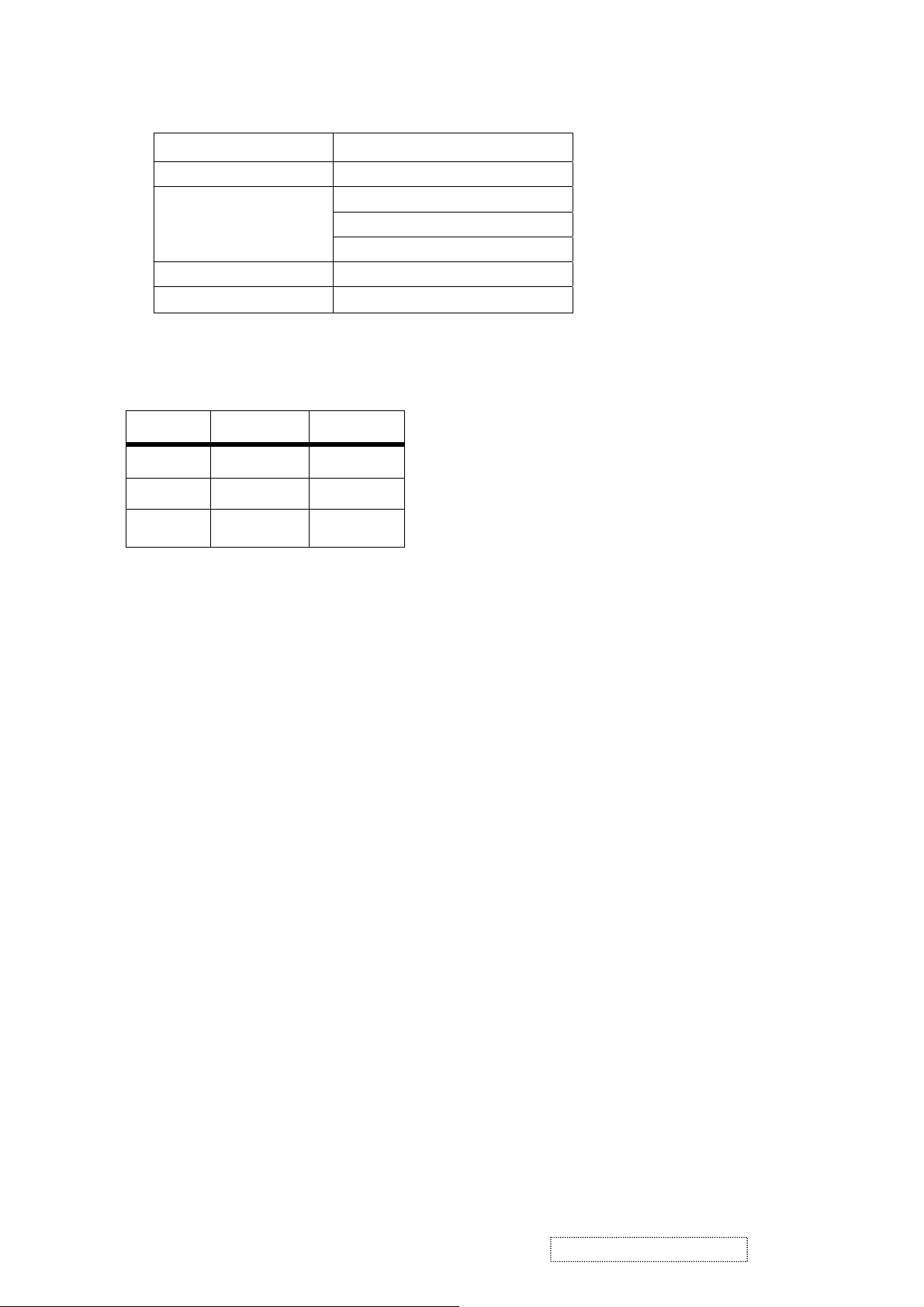
3.2.2 Power Management
State Power Indicator
On 36Watts Blue
Standby < 1Watts Amber
<1.8Arms@90Vac
100A(Max) at 90Vac(cold start)
Off <1Watts Off
3.3 Acceptable timing
If the timing is within following specification, this LCD display can automatically function with a certain
position.
Horizontal: Sync frequency: 30~82 kHz
Vertical: Sync frequency: 50~85*Hz
3.4 Signal level and input impedance
3.4.1 Video Signal level: 0.7Vp-p Video signal.
3.4.2 Sync Signal level
H/V Separate: TTL level
3.4.3 Input impedance
Analog video input: 75 ohm
Digital video input: 100 ohm
Sync input: > 1 k ohm
Audio input: 10K ohm
4. SIGNAL CABLE: Signal cable with Mini D-Sub 15P connectors at both ends. Length: 1.8 meter.
ViewSonic Corporation Confidential
15
-
Do Not Copy VA912/b-4

5. EDID data
5.1. Analog EDID: Analog EDID is stored in U8.
Time: 15:03:33
Date: Fri Aug 05, 2005
______________________________________________________________________
______________________________________________________________________
VIEWSONIC CORPORATION
EDID Version # 1, Revision # 3
DDCTest For: ViewSonic VA912-4SERIES
______________________________________________________________________
______________________________________________________________________
EDID Block 0, Bytes 0-127
128 BYTES OF EDID CODE:
0 1 2 3 4 5 6 7 8 9
________________________________________
0 | 00 FF FF FF FF FF FF 00 5A 63
10 | 1C 72 00 00 00 00 01 0F 01 03
20 | 08 26 1E 78 2E FD 56 A5 53 4A
30 | 9D 24 14 4F 54 BF EF 80 81 80
40 | 81 40 71 4F 61 59 45 59 31 59
50 | 01 01 01 01 30 2A 00 98 51 00
60 | 2A 40 30 70 13 00 78 2D 11 00
70 | 00 1E 00 00 00 FF 00 50 57 38
80 | 30 35 30 31 30 30 30 30 31 0A
90 | 00 00 00 FD 00 32 55 1E 52 0E
100 | 00 0A 20 20 20 20 20 20 00 00
110 | 00 FC 00 56 41 39 31 32 2D 34
120 | 53 45 52 49 45 53 00 18
______________________________________________________________________
(08-09) ID Manufacturer Name ________________ = VSC
(11-10) Product ID Code _____________________ = 721C
(12-15) Last 5 Digits of Serial Number ______ = Not Used
(16) Week of Manufacture _________________ = 01
(17) Year of Manufacture _________________ = 2005
(10-17) Complete Serial Number ______________ = See Descriptor Block
(18) EDID Version Number _________________ = 1
(19) EDID Revision Number ________________ = 3
(20) VIDEO INPUT DEFINITION:
Analog Signal
0.700, 0.300 (1.000 Vp-p)
Separate Syncs
(21) Maximum Horizontal Image Size ________________ = 380 mm
(22) Maximum Vertical Image Size __________________ = 300 mm
(23) Display Gamma ________________________________ = 2.20
(24) Power Management and Supported Feature(s):
Active Off/Very Low Power, Standard Default Color Space,
ViewSonic Corporation Confidential
16
-
Do Not Copy VA912/b-4

Preferred Timing Mode
Display Type = R/G/B Color
(25-34) CHROMA INFO:
Red X - 0.647 Green X - 0.292 Blue X - 0.142 White X - 0.310
Red Y - 0.327 Green Y - 0.614 Blue Y - 0.079 White Y - 0.330
(35) ESTABLISHED TIMING I:
720 X 400 @ 70Hz (IBM,VGA)
640 X 480 @ 60Hz (IBM,VGA)
640 X 480 @ 67Hz (Apple,Mac II)
640 X 480 @ 72Hz (VESA)
640 X 480 @ 75Hz (VESA)
800 X 600 @ 56Hz (VESA)
800 X 600 @ 60Hz (VESA)
(36) ESTABLISHED TIMING II:
800 X 600 @ 72Hz (VESA)
800 X 600 @ 75Hz (VESA)
832 X 624 @ 75Hz (Apple,Mac II)
1024 X 768 @ 60Hz (VESA)
1024 X 768 @ 70Hz (VESA)
1024 X 768 @ 75Hz (VESA)
1280 X 1024 @ 75Hz (VESA)
(37) Manufacturer's Reserved Timing:
1152 X 870 @ 75Hz (Apple,Mac II)
(38-53) Standard Timing Identification:
1280 X 1024 @60Hz
1280 X 960 @60Hz
1152 X 864 @75Hz
1024 X 768 @85Hz
800 X 600 @85Hz
640 X 480 @85Hz
Not Used
Not Used
______________________________________________________________________
(54-71) Detailed Timing / Descriptor Block 1:
1280x1024 Pixel Clock: 108.00 MHz
______________________________________________________________________
Horizontal Image Size: 376 mm Vertical Image Size: 301 mm
Refreshed Mode: Non-Interlaced Normal Display - No Stereo
Horizontal:
Active Time: 1280 pixels Blanking Time: 408 pixels
Sync Offset: 48 pixels Sync Pulse Width: 112 pixels
Border: 0 pixels Frequency: 63.98 KHz
Ver t i c al:
Active Time: 1024 lines Blanking Time: 42 lines
Sync Offset: 1 lines Sync Pulse Width: 3 lines
ViewSonic Corporation Confidential
17
-
Do Not Copy VA912/b-4

Border: 0 lines Frequency: 60.02 Hz
Digital Separate, Horizontal Polarity (+) Vertical Polarity (+)
______________________________________________________________________
(72-89) Detailed Timing / Descriptor Block 2:
Monitor Serial Number:
PW8050100001
______________________________________________________________________
(90-107) Detailed Timing / Descriptor Block 3:
Monitor Range Limits:
Min Vertical Freq - 50 Hz
Max Vertical Freq - 85 Hz
Min Horiz. Freq - 30 KHz
Max Horiz. Freq - 82 KHz
Pixel Clock - 140 MHz
Secondary GTF - Not Supported
______________________________________________________________________
(108-125) Detailed Timing / Descriptor Block 4:
Monitor Name:
VA912-4SERIES
(126) No Extension EDID Block(s)
(127) CheckSum OK
5.2. Digital EDID: Digital EDID is stored in U5.
Time: 15:02:23
Date: Fri Aug 05, 2005
______________________________________________________________________
______________________________________________________________________
VIEWSONIC CORPORATION
EDID Version # 1, Revision # 3
DDCTest For: ViewSonic VA912-4SERIES
______________________________________________________________________
______________________________________________________________________
EDID Block 0, Bytes 0-127
128 BYTES OF EDID CODE:
ViewSonic Corporation Confidential
18
-
Do Not Copy VA912/b-4

0 1 2 3 4 5 6 7 8 9
________________________________________
0 | 00 FF FF FF FF FF FF 00 5A 63
10 | 1C 72 00 00 00 00 01 0F 01 03
20 | 80 26 1E 78 2E FD 56 A5 53 4A
30 | 9D 24 14 4F 54 BF EF 80 81 80
40 | 81 40 71 4F 61 59 45 59 31 59
50 | 31 0A 01 01 30 2A 00 98 51 00
60 | 2A 40 30 70 13 00 78 2D 11 00
70 | 00 1E 00 00 00 FF 00 50 57 38
80 | 30 35 30 31 30 30 30 30 31 0A
90 | 00 00 00 FD 00 32 55 1E 52 0E
100 | 00 0A 20 20 20 20 20 20 00 00
110 | 00 FC 00 56 41 39 31 32 2D 34
120 | 53 45 52 49 45 53 00 67
______________________________________________________________________
(08-09) ID Manufacturer Name ________________ = VSC
(11-10) Product ID Code _____________________ = 721C
(12-15) Last 5 Digits of Serial Number ______ = Not Used
(16) Week of Manufacture _________________ = 01
(17) Year of Manufacture _________________ = 2005
(10-17) Complete Serial Number ______________ = See Descriptor Block
(18) EDID Version Number _________________ = 1
(19) EDID Revision Number ________________ = 3
(20) VIDEO INPUT DEFINITION:
Digital Signal
Non - VESA DFP 1.x Compatible
(21) Maximum Horizontal Image Size ________________ = 380 mm
(22) Maximum Vertical Image Size __________________ = 300 mm
(23) Display Gamma ________________________________ = 2.20
(24) Power Management and Supported Feature(s):
Active Off/Very Low Power, Standard Default Color Space,
Preferred Timing Mode
Display Type = R/G/B Color
(25-34) CHROMA INFO:
Red X - 0.647 Green X - 0.292 Blue X - 0.142 White X - 0.310
Red Y - 0.327 Green Y - 0.614 Blue Y - 0.079 White Y - 0.330
(35) ESTABLISHED TIMING I:
720 X 400 @ 70Hz (IBM,VGA)
640 X 480 @ 60Hz (IBM,VGA)
640 X 480 @ 67Hz (Apple,Mac II)
640 X 480 @ 72Hz (VESA)
640 X 480 @ 75Hz (VESA)
800 X 600 @ 56Hz (VESA)
800 X 600 @ 60Hz (VESA)
(36) ESTABLISHED TIMING II:
ViewSonic Corporation Confidential
19
-
Do Not Copy VA912/b-4

800 X 600 @ 72Hz (VESA)
800 X 600 @ 75Hz (VESA)
832 X 624 @ 75Hz (Apple,Mac II)
1024 X 768 @ 60Hz (VESA)
1024 X 768 @ 70Hz (VESA)
1024 X 768 @ 75Hz (VESA)
1280 X 1024 @ 75Hz (VESA)
(37) Manufacturer's Reserved Timing:
1152 X 870 @ 75Hz (Apple,Mac II)
(38-53) Standard Timing Identification:
1280 X 1024 @60Hz
1280 X 960 @60Hz
1152 X 864 @75Hz
1024 X 768 @85Hz
800 X 600 @85Hz
640 X 480 @85Hz
640 X 400 @70Hz
Not Used
______________________________________________________________________
(54-71) Detailed Timing / Descriptor Block 1:
1280x1024 Pixel Clock: 108.00 MHz
______________________________________________________________________
Horizontal Image Size: 376 mm Vertical Image Size: 301 mm
Refreshed Mode: Non-Interlaced Normal Display - No Stereo
Horizontal:
Active Time: 1280 pixels Blanking Time: 408 pixels
Sync Offset: 48 pixels Sync Pulse Width: 112 pixels
Border: 0 pixels Frequency: 63.98 KHz
Vertical:
Active Time: 1024 lines Blanking Time: 42 lines
Sync Offset: 1 lines Sync Pulse Width: 3 lines
Border: 0 lines Frequency: 60.02 Hz
Digital Separate, Horizontal Polarity (+) Vertical Polarity (+)
______________________________________________________________________
(72-89) Detailed Timing / Descriptor Block 2:
Monitor Serial Number:
PW8050100001
______________________________________________________________________
(90-107) Detailed Timing / Descriptor Block 3:
ViewSonic Corporation Confidential
20
-
Do Not Copy VA912/b-4

Monitor Range Limits:
Min Vertical Freq - 50 Hz
Max Vertical Freq - 85 Hz
Min Horiz. Freq - 30 KHz
Max Horiz. Freq - 82 KHz
Pixel Clock - 140 MHz
Secondary GTF - Not Supported
______________________________________________________________________
(108-125) Detailed Timing / Descriptor Block 4:
Monitor Name:
VA912-4SERIES
(126) No Extension EDID Block(s)
(127) CheckSum OK
6. THEORY OF OPERATION
This section describes the function of the LCD monitor per functional block.
This monitor includes MB board, power/inverter board and button board.
6.1 MB BOARD
The MB board is a two-layer, single-landed. 5V and 12V DC power from the power adapter enters the board
through connector CN1. Other connectors on the board are for audio and button board .The VGA cable is a signal
cable that contains video signal, sync signal and DDC signal from PC VGA adapter. This system board consists of
4 functional areas: flat panel controller, flash ROM, power regulator and Audio amplifier
6.1.1 Flat panel controller… RTD2523 (U6)
The heart of the system board is the scalar chip of RTD2523. The RTD2523 is a high performance, dual input
graphics processing IC for LCD monitors with resolutions up to SXGA. It provides all key IC functions required
for LCD panel. On-chip functions include an 8-bit triple ADC, PLL, DVI receiver, high scaling engine, OSD
controller and dual LVDS transmitter.
a) Clock Generation:
Crystal Input Clock (XIN and XOUT): This is the input pair to an internal crystal oscillator and
corresponding logic. A 24.576 MHz crystal is recommended.
b) Hardware Reset (Pin 56):
Hardware Reset signal is provided to MCU (I1). It is active high.
c) Analog to Digital Converter:
The RTD2523 chip has three ADC's (analog-to-digital converters), one for each color (red, green and
blue) .The analog RGB and synchronous signals are connected to RTD2523 as described below:
Pin Name Pin Number
Red + 37
Red - 38
Green + 34
ViewSonic Corporation Confidential
21
-
Do Not Copy VA912/b-4

Green - 35
Blue + 30
Blue - 31
H sync 42
V sync 43
d) Embedded OSD: Embedded 11.25K SRAM dynamically stores OSD command and fonts.
e) On chip TMDS receiver: The RTD2523 integrated TMDS receiver, which operates up to 165MHz and can
directly connect to all DVI compliant TMDS transmitters. The TMDS signals are connected to RTD2523 as
described bellow:
Pin Name Pin NO.
TX0+ 20
TX0- 21
TX1+ 18
TX1- 17
TX2+ 15
TX2- 14
TXC+ 23
TXC- 24
f) PWM controlling function (Pin 112, Pin 113): The RTD2523 has two dedicated PWM outputs of PWM0
and PWM1 to control audio volume and back light brightness.
g) Serial interface ports (pin 70 and pin 71): This serial interface ports communicate with MCU and support
up to 400Kbit per second transmit rate.
h) Panel interface (Pin 85~94, Pin 73~82,) : The RTD2523 driver interface is highly programmable. It
supports dual /Single LVDS interface output.
6.1.2 Power Regulator AIC1117 (U1, U3): The AIC1117 is a low dropout positive adjustable regulator with
minimum of 800mA output current capability.
So it is well suited for 3.3 V and 2.5 V Regulator.
U3 as a 2.5V regulator, Desired output voltage are determined by the equation
Volt=1.25 x (1 + R17/R15)= 2.5
U1 as a 3.3V regulator, Desired output voltage are determined by the equation
Volt=1.255 x (1+ R6/R3)= 3.3
6.2 Audio Amplifier UTC TDA7496L(U9)
The TDA7496L is a stereo 2W+2W class AB power amplifier; Features of the TDA7496L include linear volume
control, Stand-by and mute functions.
6.3 Power/Inverter Board
This is a specific power/inverter for VA912 monitor 45W 5V + 12V power and backlight which converters
12Vdc to drive four cold cathode fluorescence tubes. Electrical specification described as below.
6.3.1 Inverter Electrical specification described as below.
INPUT
Rated Input Voltage 12Vdc
Input Voltage Range 11.4~12.6Vdc
Input Current <1.96A
Off state Input Power <0.1W
ViewSonic Corporation Confidential
22
-
Do Not Copy VA912/b-4

On / off control Voltage 2~5.25 for on, 0~0.13 for off
OUTPUT
Rated Output Strike-on Voltage 1500~2000Vrms
Rated Output Voltage 710Vrms at 6mA
Rated Output Frequency 40~50KHz
Rated Output Current 6~7mA
6.3.2 Power Electrical specification described as below.
INPUT
Rated Input Voltage 90~264Vac, 47~63Hz
Operation Input Voltage 100~240Vac, 50~60Hz
Input Current <1.8A@90Vac
Inrush Current <100A @ 90Vac(Cold start)
Efficiency 80 % TYPICAL AT 115VAC FULL LOAD
OUTPUT
Output Voltage Regulation +/-5%
Output Ripple and Noise 120 mVp-p
Rated Output Current <4.16A
Turn-on Delay <3 seconds
ViewSonic Corporation Confidential
23
-
Do Not Copy VA912/b-4

5. Adjustment Procedure
1. Function test
(1) Test equipment
Color video signal and pattern generator (or PC with SXGV resolution)
(2) Test condition
Before function testing and alignment, the unit must warm up for at least 30 minutes under the
following conditions:
1. Room temperature
2. With full-white screen , RGB , black pattern
3. with cycled display modes.
2. Test display modes
Item Timing Analog Digital
1 640 x 350 @ 70Hz, 31.5kHz Yes Yes
2 640 x 400 @ 60Hz, 31.5kHz Yes Yes
3 640 x 400 @ 70Hz, 31.5kHz Yes Yes
4 640 x 480 @ 60Hz, 31.5kHz Yes Yes
5 640 x 480 @ 67Hz, 35.0kHz Yes Yes
6 640 x 480 @ 72Hz, 37.9kHz Yes Yes
7 640 x 480 @ 75Hz, 37.5kHz Yes Yes
8 640 x 480 @ 85Hz, 43.27kHz Yes Yes
9 720 x 400 @ 70Hz, 31.5kHz Yes Yes
10 800 x 600 @ 56Hz, 35.1kHz Yes Yes
11 800 x 600 @ 60Hz, 37.9kHz Yes Yes
12 800 x 600 @ 75Hz, 46.9kHz Yes Yes
13 800 x 600 @ 72Hz, 48.1kHz Yes Yes
14 800 x 600 @ 85Hz, 53.7kHz Yes Yes
15 832 x 624 @ 75Hz, 49.7kHz Yes Yes
16 1024 x 768 @ 60Hz, 48.4kHz Yes Yes
17 1024 x 768 @ 70Hz, 56.5kHz Yes Yes
18 1024 x 768 @ 72Hz, 58.1kHz Yes Yes
19 1024 x 768 @ 75Hz, 60.0kHz Yes Yes
20 1024 x 768 @ 85Hz, 68.67kHz Yes Yes
21 1152 x 870 @ 75Hz, 68.7kHz Yes Yes
22 1280 x 1024 @ 60Hz, 63.4kHz Yes Yes
23 1280 x 1024 @ 75Hz, 79.97kHz Yes Yes
24 1280x 720 @ 60Hz, 45kHz (HDTV) Yes Yes
ViewSonic Corporation Confidential
24
-
Do Not Copy VA912/b-4

3. Test pattern
Item Test condition Pattern Specification Remark
1 Frequency & performance Cross-hatch pattern No noise is allowed, all colors must
be clear
2 Monitor saturation 16-gray scale pattern 3 to 4 levels must be saturated when
brightness and contrast are set to
100%
3 RGB color performance RGB color Check the color temperature of
RGB signal color
4 Sub-pixel defect RGB color Check the sub-pixel defect Pattern 3,
5 Full white Full white Check the brightness and contrast
ratio, and check for bright pixel
defects
6 Full black Full black Pattern 7
7. 5-cycle pattern 5-cycle pattern Check the BU Pattern 8
8. 1-dot pattern 1-dot pattern Check the flicker Pattern 9
Pattern 1
Pattern 2
Pattern 3,
4, 5
4 , 5
Pattern 6
Pattern 1 Pattern2
Pattern 3 Pattern4
ViewSonic Corporation Confidential
25
-
Do Not Copy VA912/b-4

Pattern 5 Pattern6
Pattern 7 Pattern 8
Pattern 9
ViewSonic Corporation Confidential
26
-
Do Not Copy VA912/b-4

OSD Function Menu
A. When in Analog Input Mode
1. Main Menu
Press the [1] (Menu) button to enter the Main Menu:
Press the [▲] button to highlight the previous item or the [▼] button to highlight
the next item.
Press the [1] (Menu) button to exit the Main Menu.
(1) Auto Image Adjust Page:
Press the [2] button to execute the auto image adjust function.
Press the [1] button to exit the page.
(2) Contrast/Brightness Page:
Press the [2] button to enter the contrast adjustment page.
Press the [1] button to exit the page.
1) Contrast Item
Press the [▲] button to increase the contrast.
Press the [▼] button to decrease the contrast.
Press the [2] button to enter the brightness adjustment page.
Press the [1] button to exit the page.
2) Brightness Item
Press the [▲] button to increase the brightness.
Press the [▼] button to decrease the brightness.
Press the [2] button to enter the contrast adjustment page.
Press the [1] button to exit the page.
(3) Input Select Page:
Press the [2] button to switch to digital input mode.
(4) Audio Adjust Page:
Press the [▲] button to increase the volume.
Press the [▼] button to decrease the volume.
Press the [2] button to enable or disable mute function .
Press the [1] button to exit the page.
(5) Color Adjust Page:
Press the [2] button to enter the color adjustment page.
Press the [1] button to exit the page.
Press the [▲] button to highlight the previous item or the [▼] button to
highlight the next item.
1) sRGB Item
2) 9300K Item
3) 6500K Item
4) 5400K Item
5) 5000K Item
Press the [2] button to select the currently highlighted item.
Press the [1] button to exit the currently highlighted item.
6) User Color Item
Press the [2] button to enter the user color page.
ViewSonic Corporation Confidential
27
-
Do Not Copy VA912/b-4

Press the [1] button to exit the page.
Red, Green, Blue Options:
Press the [2] button to cycle among the colors.
Press the [1] button to exit the page.
Press the [▲] button to increase the selected color level.
Press the [▼] button to decrease the selected color level.
(6) Information Page:
Press the [2] button to enter the information page.
Press the [1] button to exit the information page.
(7) Manual Image Adjust Page:
Press the [2] button to enter the manual image adjustment page.
Press the [1] button to exit the page.
Press the [▲] button to highlight the previous item or the [▼] button to
highlight the next item.
1) H./V. Position Item
Press the [2] button to enter the horizontal/vertical postion adjustment page.
Press the [1] button to exit the page.
a) Horizontal Position:
Press the [2] button to enter the vertical position adjustment page.
Press the [1] button to exit the page.
Press the [▲] button to shift the image to the right.
Press the [▼] button to shift the image to the left.
b) Vertical Position:
Press the [2] button to return to the horizontal position adjustment page.
Press the [1] button to exit the page.
Press the [▲] button to shift the image upward.
Press the [▼] button to shift the image downward.
2) Horizontal Size Item
Press the [2] button to enter the horizontal size adjustment page.
Press the [1] button to exit the page.
Press the [▲] button to make the image wider.
Press the [▼] button to make the image narrower.
3) Fine tune Item
Press the [2] button to enter the fine tuning page.
Press the [1] button to exit the page.
Press “[▲]” Button to adjust character position in one direction.
Press “[▼]“Button to adjust character position in the other direction.
4) Sharpness Item
Press the [2] button to enter the sharpness adjustment page.
Press the [1] button to exit the page.
Press “[▲]” Button to increase image sharpness.
Press “[▼]“ Button to decrease image sharpness.
(8) Setup Menu Page:
ViewSonic Corporation Confidential
28
-
Do Not Copy VA912/b-4

Press the [2] button to enter the setup menu page.
Press the [1] button to exit the page.
Press the [▲] button to highlight the previous item or the [▼] button to
highlight the next item.
1) Language Select Item
Press the [2] button to enter the language selection page.
Press the [1] button to exit the page.
Press the [▲] button to highlight the previous item or the [▼] button to
highlight the next item.
English, French… Option
Press the [2] button to select the language.
Press the [1] button to exit the page.
2) Resolution Notice Item
Press the [2] button to enter the resolution notice page.
Press the [1] button to exit the page.
Enable, Disable Option
Press the [2] button to select the highlighted option.
Press the [1] button to exit the page.
Press the [▲] button to highlight the previous option or the [▼] button
to highlight the next option.
3) OSD Position Item
Press the [2] button to enter the OSD position adjustment page.
Press the [1] button to exit the page.
a) Horizontal Position Option
Press the [2] button to enter the vertical position adjustment page.
Press the [1] button to exit the page.
Press the [▲] button to shift the menu to the right.
Press the [▼] button to shift the menu to the left.
b) Vertical Position Option:
Press the [2] button to enter the horizontal position adjustment page.
Press the [1] button to exit the page.
Press the [▲] button to shift the menu upward.
Press the [▼] button to shift the menu downward.
4) OSD Time Out Item
Press the [2] button to enter the OSD time out adjustment page.
Press the [1] button to exit the page.
Press the [▲] button to increase the OSD time out.
Press the [▼] button to decrease the OSD time out.
5) OSD Background Item
Press the [2] button to enter the OSD background selection page.
Press the [1] button to exit the page.
Enable, Disable Option
Press the [▲] button to highlight the previous option or the [▼] button
to highlight the next option.
Press the [2] button to select the highlighted option.
ViewSonic Corporation Confidential
28
-
Do Not Copy VA912/b-4

Press the [1] button to exit the page.
(9) Memory Recall Page
Press the [2] button to execute the memory recall function.
Press the [1] button to exit the page.
2. Other Menu:
This “shortcut” menu is directly accessible without bringing up the OSD.
(1) Contrast Dialog
Press the [▲] or [▼] button to enter the Contrast Dialog.
Press the [1] button to exit the Contrast Dialog.
Press the [2] button to enter the Brightness Dialog.
Press the [▲] button to increase the contrast.
Press the [▼] button to decrease the contrast.
(2) Brightness Dialog
Press the [▲] or [▼] button to enter the Brightness Dialog.
Press the [1] button to exit the Brightness Dialog.
Press the [2] button to enter the Contrast Dialog.
Press the [▲] button to increase the brightness.
Press the [▼] button to decrease the brightness.
(3) Analog/Digital Dialog
Press the [2] button to toggle between analog and digital modes.
B. When in Digital Input Mode
1. Main Menu
Press the [1] (Menu) button to enter the Main Menu:
Press the [▲] button to highlight the previous item or the [▼] button to highlight
the next item.
Press the [1] (Menu) button to exit the Main Menu.
(1) Auto Image Adjust Page:
Press the [2] button to execute the auto image adjust function.
Press the [1] button to exit the page.
(2) Contrast/Brightness Page:
Press the [2] button to enter the contrast adjustment page.
Press the [1] button to exit the page.
1) Contrast Item
Press the [▲] button to increase the contrast.
Press the [▼] button to decrease the contrast.
Press the [2] button to enter the brightness adjustment page.
Press the [1] button to exit the page.
2) Brightness Item
Press the [▲] button to increase the brightness.
Press the [▼] button to decrease the brightness.
Press the [2] button to enter the contrast adjustment page.
Press the [1] button to exit the page.
ViewSonic Corporation Confidential
30
-
Do Not Copy VA912/b-4

(3) Input Select Page:
Press the [2] button to switch to analog input mode.
(4) Audio Adjust Page:
Press the [▲] button to increase the volume.
Press the [▼] button to decrease the volume.
Press the [2] button to enable or disable mute function .
Press the [1] button to exit the page.
(4) Color Adjust Page:
Press the [2] button to enter the color adjustment page.
Press the [1] button to exit the page.
Press the [▲] button to highlight the previous item or the [▼] button to
highlight the next item.
1) sRGB Item
2) 9300K Item
3) 6500K Item
4) 5400K Item
5) 5000K Item
Press the [2] button to select the currently highlighted item.
Press the [1] button to exit the currently highlighted item.
6) User Color Item
Press the [2] button to enter the user color page.
Press the [1] button to exit the page.
Red, Green, Blue Options:
Press the [2] button to cycle among the colors.
Press the [1] button to exit the page.
Press the [▲] button to increase the selected color level.
Press the [▼] button to decrease the selected color level.
(5) Information Page:
Press the [2] button to enter the information page.
Press the [1] button to exit the information page.
(6) Manual Image Adjust Page:
Press the [2] button to enter the manual image adjustment page.
Press the [1] button to exit the page.
Press the [▲] button to highlight the previous item or the [▼] button to
highlight the next item.
1) Sharpness Item
Press the [2] button to enter the sharpness adjustment page.
Press the [1] button to exit the page.
Press “[▲]” Button to increase image sharpness.
Press “[▼]“ Button to decrease image sharpness.
(7) Setup Menu Page:
Press the [2] button to enter the setup menu page.
Press the [1] button to exit the page.
ViewSonic Corporation Confidential
31
-
Do Not Copy VA912/b-4

Press the [▲] button to highlight the previous item or the [▼] button to
highlight the next item.
1) Language Select Item
Press the [2] button to enter the language selection page.
Press the [1] button to exit the page.
Press the [▲] button to highlight the previous item or the [▼] button to
highlight the next item.
English, French… Option
Press the [2] button to select the language.
Press the [1] button to exit the page.
2) Resolution Notice Item
Press the [2] button to enter the resolution notice page.
Press the [1] button to exit the page.
Enable, Disable Option
Press the [2] button to select the highlighted option.
Press the [1] button to exit the page.
Press the [▲] button to highlight the previous option or the [▼] button
to highlight the next option.
3) OSD Position Item
Press the [2] button to enter the OSD position adjustment page.
Press the [1] button to exit the page.
a) Horizontal Position Option
Press the [2] button to enter the vertical position adjustment page.
Press the [1] button to exit the page.
Press the [▲] button to shift the menu to the right.
Press the [▼] button to shift the menu to the left.
b) Vertical Position Option:
Press the [2] button to enter the horizontal position adjustment page.
Press the [1] button to exit the page.
Press the [▲] button to shift the menu upward.
Press the [▼] button to shift the menu downward.
4) OSD Time Out Item
Press the [2] button to enter the OSD time out adjustment page.
Press the [1] button to exit the page.
Press the [▲] button to increase the OSD time out.
Press the [▼] button to decrease the OSD time out.
5) OSD Background Item
Press the [2] button to enter the OSD background selection page.
Press the [1] button to exit the page.
Enable, Disable Option
Press the [▲] button to highlight the previous option or the [▼] button
to highlight the next option.
Press the [2] button to select the highlighted option.
Press the [1] button to exit the page.
ViewSonic Corporation Confidential
32
-
Do Not Copy VA912/b-4

(8) Memory Recall Page
Press the [2] button to execute the memory recall function.
Press the [1] button to exit the page.
2. Other Menu:
This “shortcut” menu is directly accessible without bringing up the OSD.
(1) Contrast Dialog
Press the [▲] or [▼] button to enter the Contrast Dialog.
Press the [1] button to exit the Contrast Dialog.
Press the [2] button to enter the Brightness Dialog.
Press the [▲] button to increase the contrast.
Press the [▼] button to decrease the contrast.
(2) Brightness Dialog
Press the [▲] or [▼] button to enter the Brightness Dialog.
Press the [1] button to exit the Brightness Dialog.
Press the [2] button to enter the Contrast Dialog.
Press the [▲] button to increase the brightness.
Press the [▼] button to decrease the brightness.
(3) Analog/Digital Dialog
Press the [2] button to toggle between analog and digital modes.
C. Other Information
When the “No Signal” or “Out of Range” messages appear:
If no input signal is detected, the “No Signal” message will appear in the center of
the screen.
If the V-Sync signal rate is greater than than 85Hz or its resolution is greater than
SXGA, the “Out of Range” message will appear in the center of the screen.
Activating Factory Mode and Burn Mode:
While the device is in standby, press the [2] button, then press the power button to
enter Factory Mode. While Factory Mode is active, an additional menu page titled
“Factory Menu” will be accessible. Press the [2] button to enter the Factory Menu
page, then press the [2] button to enter Burn Mode.
When Installing a New Main Board
1. Enter Factory Mode.
2. Use a PC or chrom to send a 32-tone gray scale signal to the monitor.
3. Select “Auto Color”
ViewSonic Corporation Confidential
33
-
Do Not Copy VA912/b-4

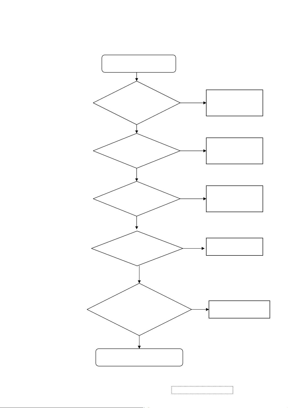
6. Troubleshooting
No power
No Power
Check CN1 pin 5,6
5V correct?
OK
Check U1 pin2
Output 3.3V?
OK
Check U3 pin 2
Output 2.5V?
OK
Check X’tal Y1=24.576MHz?
And Y2=11.092MHz?
No
No
No
No
Change power
board module
Change U1.
Change U3
Change Y1 or Y2
OK
Check button cable
No
& button board?
Change cable or
button board
OK
Change M/B
ViewSonic Corporation Confidential
34
-
Do Not Copy VA912/b-4
y
)
Q
No Audio
No Audio Output
Check Input
Signal J3 OK?
No
Check Input source
or Change J3
OK
Check JP2 to
Speaker OK?
No
Change Speaker or
JP2(Cable)
OK
Check CN1 pin
1,2=12V?
No
Change power
board module
OK
Check U9(pin6)
Volume and
15
No
Change Q15
OK
Check U9
pin12(Mute),pin11(
Stb
No
Change U9
OK
Change M/B
ViewSonic Corporation Confidential
35
-
Do Not Copy VA912/b-4

p
Display color abnormal:
Display color abnormal
Check panel
cable?
No
Change panel cable
OK
Check open/short
of U6
No
Repair open/short
OK
Check panel
ower supplyof
No
Change Q8
OK
Check panel
No
Change panel
OK
Change M/B
ViewSonic Corporation Confidential
36
-
Do Not Copy VA912/b-4

front bezel ass'y
1
C-00004172
back cover
1
CB-00004149
Audio cable
1
CB-00002602
VGA cable
1
Screw
6
M-MS-0808-9682
JXL9V001010
LCD FILM
1
cushion
1
cushion
1
RECOMMENDED SPARE PARTS LIST (VA912-4)
ViewSonic Model Number: VS10867-1W
7. Recommended Spare Parts List
Rev: 1a
Serial No. Prefix: PW7
Item ECR/ECN ViewSonic P/N Ref. P/N Location Universal number# Q'ty
Accessories:
1
Board Assembly:
2 Power board B-00003993 AS05B312D00 Power board 1
3 Main Board B-00004169 21L9TAMB090 Main board 1
4 Button board B-00004170 23L9VABB003 Button board 1
Cabinets:
5 Front bezel assy C-00004171
6 Base Assembly C-00004147 38W0VABS010 base assy 1
7
Cables:
8 Cable MB-LCD CB-00002525 DD0L9VLC015 Cable MB-LCD 1
9
10
11 Cable MB-BB CB-00004173 DDL9VABU001 Cable MB-BB 1
Documentation:
12
Electronic
13 19" HSD TFT LCD panel E-00004175 AA90ME13006 LCD panel (2nd source) 1
Components:
14 19" HSD TFT LCD panel E-00004176 AA90ME13014 LCD panel 1
15 Speaker assy E-00004177 DN0TE200F00 speaker assy 1
Hardware:
16 Screw M3.0*4.0-I(NI) GP M-SCW-0824-6802 MM30040IBJ9 Screw 8
17 Screw M3.0*6, B(NI) GP M-SCW-0824-0814
18 Screw F4.0*14-I(BNI) GP HW-00004157 MF40140IJ29 Screw 7
Miscellaneous:
19
Packing Material:
20 EPE bags M-MS-0808-9158 HAL7V002019 EPE bags 1
21 Carton P-00004178 HFL9VA02013 carton 1
22 End cap (L) P-00004179
23 End cap (R) P-00004180
Plastics:
24
Description
Power cable A-00003642 DM33T181004 Power cable 1
24L9VALB012
Back Cover Assembly
Audio cable
VGA cable
User manual + CD wizard DC-00004174 HFL9VA02013 User manual 1
LCD film
Stand assy PL-00004163 26W0VASA016 Stand ASSY 1
25L9VALC010
DD0L0TPC007
DDL7VDPC005
MM30060BBJ3
HBL9VA01013
HBL9VA02010
ViewSonic Corporation Confidential
37
-
Do Not Copy VA912/b-4
Rev: 1a
Serial No. Prefix: PW8
RECOMMENDED SPARE PARTS LIST (VA912b-4)
ViewSonic Model Number: VS10867-1W
Item ECR/ECN ViewSonic P/N Ref. P/N Location Universal number# Q'ty
Accessories:
1
Board Assembly:
2 Power board B-00003993 AS05B312D00 Power board 1
3 Main Board B-00004169 21L9TAMB090 Main board 1
4 Button board B-00004170 23L9VABB003 Button board 1
Cabinets:
5 Front bezel assy C-00004181
6 Base Assy C-00004165 38W0VABS001 base assy 1
7
Cables:
8 Cable MB-LCD CB-00002525 DD0L9VLC015 Cable MB-LCD 1
9 Audio cable CB-00004149 DD0L0TPC007 Audio cable 1
10 VGA cable CB-00002602 DDL7VDPC005 VGA cable 1
11 Cable MB-BB CB-00004173 DDL9VABU001 Cable MB-BB 1
Documentation:
12
Electronic
13 19" HSD TFT LCD panel E-00004175 AA90ME13006
Components:
14 19" HSD TFT LCD panel E-00004176 AA90ME13014 LCD panel 1
15 Speaker assy E-00004177 DN0TE200F00 speaker assy 1
Hardware:
16 Screw M3.0*4.0-I(NI) GP M-SCW-0824-6802 MM30040IBJ9 Screw 8
17 Screw M3.0*6, B(NI) GP M-SCW-0824-0814
18 Screw F4.0*14-I(BNI) GP HW-00004157 MF40140IJ29 Screw 7
Miscellaneous:
19
Packing Material:
20 PE bags P-00004159 HAL0T002019 PE bags 1
21 Carton P-00004183 HFL9VA01017 carton 1
22 End cap (L) P-00004179
23 End cap (R) P-00004180
Plastics:
24
Description
Power cable A-00003642 DM33T181004 Power cable 1
24L9VALB004
Back Cover Assy
User manual + CD wizard DC-00004174 HFL9VA02013 User manual 1
LCD film M-MS-0808-9682 JXL9V001010 LCD FILM 1
Stand assy PL-00004168 26W0VASA008 Stand ASSY 1
C-00004182
25L9VALC001
MM30060BBJ3
HBL9VA01013
HBL9VA02010
front bezel ass'y 1
back cover 1
Screw 6
cushion 1
cushion 1
1
ViewSonic Corporation Confidential
38
-
Do Not Copy VA912/b-4
ViewSonic Model Number: VS10867-1W
Item
ViewSonic P/N
Ref. P/N
Description
Location
Universal number#
Q'ty
1
#N/A
1L9VAZXVS09
L9VA LCD MONITOR(USA) GP
2
B-00004169
21L9TAMB090
L9TA M/B ASSY(RTD2523-LF) GP
13#N/A
31L9TASS079
L9TA M/B S/S ASSY(RTD2523-LF) GP
1
,EC3,EC5,EC6
5
#N/A
CC71004MD68
CAP EC 100U 25V(+-20%,105C,6*11,LESR) GP
C70
1
7,C99,EC1
7
#N/A
BG611059327
XTAL DIP 11.0592MHZ(+-30PPM,49/US) GP
Y218
#N/A
BG624576104
XTAL DIP 24.576MHZ(+-30PPM,49/S) GP
Y119
#N/A
AL007496D29
IC(20P) UTC TDA7496LK(DIP) GP
U9110
#N/A
DFPJ05FR153
CONN DIP PHONE JACK 5P FR(H10)248C GP
J3111
#N/A
DFHD04MR132
CONN DIP HEADER 4P 1R MR(P2.0,H4.1) GP
JP2112
#N/A
DFHD10MR324
CONN DIP HEADER 10P 1R MR(P2.0,H4.1) GP
CN6113
#N/A
DFHD30MR267
CONN DIP HEADER 30P 2R MR(P2.0,H4.0) GP
CN5114
#N/A
DFHD08FR102
CONN DIP HEADER 8P 2R FR(P2.54,H5.0) GP
CN1115
#N/A
DFDS15FR076
CONN D-SUB 15P 3R FR(P1.15,H12.55) GP
CN2116
#N/A
DFDI24FR108
CONN DIP DVI 24P 3R FR(P1.905,H10.04) GP
CN4117
B-00004170
23L9VABB003
L9VA BUTTON/B ASSY GP
118#N/A
DAL9VATB115
PCB(BUTTON)L9VA TB(1L,204*16,REVA) GP
119#N/A
BEYG0014DA0
LED(DIP) YELLOW/GREEN(L-3WYGW-F01) GP
LED1120
#N/A
DFHD10MR324
CONN DIP HEADER 10P 1R MR(P2.0,H4.1) GP
CN1
1
SW4,SW5,SW6
22
B-00003993
AS05B312D00
ADP/INV,FSP043-2PI01 90~264V GP
123C-00004181
24L9VALB004
L9VA LCD BEZEL ASSY GP
124#N/A
34L9VALB004
L9VA LCD BEZEL SUB ASSY GP
125#N/A
36L9VAPS001
L9VA PCB SHIELDING ASSY GP
126#N/A
FAL9VA01012
LCD BKT-L L9VA(FAL9VA01,REV3A) GP
127#N/A
FAL9VA02019
LCD BKT-R L9VA(FAL9VA02,REV3A) GP
128#N/A
FCL7B001018
POWER BOARD MYLAR
129#N/A
FCM7T004014
AL FOIL M7T(FCM7T004,REV3A) GP
330M-SCW-0824-6802
MM30040IBJ9
SCREW M3.0*4.0-I(NI) GP
831M-SCW-0824-0814
MM30060BBJ3
SCREW M3.0*6,B(NI) GP
632M-MS-0808-8986
MBLI1004018
IO NUT LI1(MBLI1004,REV3A)
433#N/A
MS35080B456
SCREW F3.5*8-B(NI)(WASHER)GP
134CB-00002525
DD0L9VLC015
CABLE MB-LCD(30P,140MM)L9V-5 GP
135CB-00004152
DD0L9VLC023
CABLE LVDS(30P,140MM,LINKTEC,AU)L9VA GP
136CB-00004173
DDL9VABU001
CABLE MB-BUTTON(10P/10P,280MM)L9VA GP
137E-00004177
DN0TE200F00
SPEAK ASSY L9VA FG-TE200 1.5W*2 GP
138#N/A
FCL5M005011
AL FOIL(PANEL) L5M(FCL5M005,REV 3A)
239M-MS-0808-9247
EBL70023013
WIRE MOUNTS L70L-E(EBL70023,REV3A) GP
140#N/A
GAL7TA01016
RUBBER FOOT L7TA(GAL7TA01,REV3A)
241#N/A
25L9VALC001
L9VA LCD COVER ASSY GP
142#N/A
EAL9VA02019
LCD COVER L9VA(EAL9VA02,REV3A) GP
143#N/A
FBL9VA01013
HINGE-PLATE L9VA(FBL9VA01,REV3A) GP
144M-MS-0808-9411
FBL70008014
LOCK METAL L70B(FBL70008,REV3A) GP
145PL-00004168
26W0VASA008
W0VA STAND ASSY GP
146#N/A
EAW0VA03011
STAND-FRONT W0VA(EAW0VA03,REV3A)GP
147#N/A
EAW0VA05013
STAND-BACK W0VA(EAW0VA05,REV4A)GP
148#N/A
FAW0VA04017
HINGE ASSY W0VA(FAW0VA04,REV3A)GP
149#N/A
FBW0VA02015
CONTACT-PLATE W0VA(FBW0VA02,REV3A)GP
150HW-00004157
MF40140IJ29
SCREW F4.0*14-I(BNI) GP
751#N/A
DDL9TATH107
CABLE STAND-HINGE(1P,150MM) GP
152M-SCW-0824-6895
MF40080IBJ1
SCREW F4.0*8-I(NI)GP
153#N/A
27L9VACS001
L9VA CHASSIS ASSY GP
154#N/A
EBL9VA02010
HINGE COVER L9VA(EBL9VA02,REV3A) GP
155#N/A
GAW0VA02014
RUBBER PLUG VESA (GAW0VA02,R3A)GRAY GP
456M-SCW-0824-6797
MF40080BJ29
SCREW F4.0*8-B(BNI) GP
257#N/A
MM40100BL61
SCREW M4*10.0-B(BNI,NYLOK) GP
658#N/A
2AL9VAPTU02
L9VA PANEL KIT ASSY(HSD 8MS) GP
159E-00004175
AA90ME13006
LCD(TFT) HSD190ME13-A02(8MS)GP
160E-00004176
AA90ME13014
LCD(TFT)19" HSD190ME13-A03 GP
161#N/A
AZL9VA0U001
L9VA SW BIOS IMAGE (W/AUDIO) FOR HSD
162#N/A
28L9VAPK008
L9VA PACKING ASSY GP
163C-00004165
38W0VABS001
W0VA BASE SUB ASSY GP
164CB-00002602
DDL7VDPC005
CABLE MB-VGA (15/15P,1.8M)L7VD GP
165CB-00003440
DD0L0TTH108
CABLE ASSY L0T MB-DVI(24P,REV2A) GP
166CB-00004149
DD0L0TPC007
CABLE AUDIO(ST,1.8M)BLACK L0T GP
167P-00004179
HBL9VA01013
END CAP-L L9VA(HBL9VA01,REV3A) GP
168P-00004180
HBL9VA02010
END CAP-R L9VA(HBL9VA02,REV3A) GP
169M-LB-0813-0747
HCL7V004013
CORE LABEL(HCL7V004,REV3A)
1
Rev: 1a
Serial No. Prefix: PW7
BOM LIST (VA912-4)
4 #N/A CC62204MD23 CAP EC 22U 25V(+-20%,105C,5*11,2KHR)GP
6 #N/A CC73303MD51 CAP EC 330U 16V(+-20%,105C,8*11,2KH)GP
21 PL-BT-0706-0127 DHP0002B108 SWITCH PUSH BUTTON(PT-002-B1,50MA,12V)GP
C34,C46,C50,C
53,C59,C84,EC2
C6,C91,C93,C9
SW1,SW2,SW3,
10
6
6
ViewSonic Corporation Confidential
39
-
Do Not Copy VA912/b-4

Item
ViewSonic P/N
Ref. P/N
Description
Location
Universal number#
Q'ty
70
#N/A
HCL9VA01014
ID LABEL L9VA(HCL9VA01,REV3A) GP
171M-LB-0813-0745
HCL7V002011
SERIAL LEBAL L7V(HCL7V002,REV3A) GP
172#N/A
HCL9VA02011
CARTON LABEL(4) L9VA(HCL9VA02,R3A) GP
173P-00004183
HFL9VA01017
CARTON L9VA(HFL9VA01,REV3A) GP
174#N/A
HGL9VA01018
CD+QSG L9VA(HGL9VA01,REV3A) GP
175#N/A
JXLM5003011
HANDLE LM5S(JXLM5003,REV 3B) GP
176M-MS-0808-9682
JXL9V001010
LCD FILM L9V(JXL9V001,REV3A) GP
177M-LB-0813-1043
HCL70021011
HI-POT LABEL L70L(HCL70021,REV3A)
178#N/A
HFL9T002018
SPACE PLATE L9T(HFL9T002,REV3A)
0.02779P-00004159
HAL0T002019
PE BAG L0T(HAL0T002,REV3A)
180#N/A
HDL7VC01019
SERVICR PAPER L7VC(HDL7VC01,REV3A) GP
181DC-00003536
HCL9V009011
HG LABEL L9VD(HCL9V009,REV3A)
182A-PC-0106-0224
DM333181G97
POWER CORD 3P 1.8M(USA)V04VS350012180 GP
1
ViewSonic Corporation Confidential
40
-
Do Not Copy VA912/b-4
Item
ViewSonic P/N
Ref. P/N
Description
Location
Universal number#
Q'ty
C34,C46,C50,C53,C59,
CONN D-SUB 15P 3R FR(P1.15,H12.55) GP
16
#N/A
DFDI24FR108
CONN DIP DVI 24P 3R FR(P1.905,H10.04) GP
CN4117
B-00004170
23L9VABB003
L9VA BUTTON/B ASSY GP
118#N/A
DAL9VATB115
PCB(BUTTON)L9VA TB(1L,204*16,REVA) GP
119#N/A
BEYG0014DA0
LED(DIP) YELLOW/GREEN(L-3WYGW-F01) GP
LED1120
#N/A
DFHD10MR324
CONN DIP HEADER 10P 1R MR(P2.0,H4.1) GP
CN1
1
B1,50MA,12V)GP
W5,SW6
29
M-MS-0808-9243
FEL7V003019
LOGO FRONT-VSC-38MM
1
35
#N/A
FCL7B001018
POWER BOARD MYLAR
1
IO NUT LI1(MBLI1004,REV3A)
SCREW F3.5*8-B(NI)(WASHER)GP
42
CB-00004152
DD0L9VLC023
CABLE LVDS(30P,140MM,LINKTEC,AU)L9VA
1
RUBBER FOOT L7TA(GAL7TA01,REV3A)
LCD COVER L9VA B(EAL9VA02,R3A) GP
LOCK METAL L70B(FBL70008,REV3A) GP
W0VA STAND ASSY (S/B) GP
STAND FRONT W0VA(EAW0VA03,R3A)BK GP
STAND-BACK W0VA(EAW0VA05,R3A)BK GP
BOM LIST (VA912b-4)
ViewSonic Model Number: VS10867-1W
Rev: 1a
Serial No. Prefix: PW8
1 #N/A 1L9VAZXVS92 L9VA LCD MONITOR(TWN)S/B GP
2 B-00004169 21L9TAMB090 L9TA M/B ASSY(RTD2523-LF) GP 1
3 #N/A 31L9TASS079 L9TA M/B S/S ASSY(RTD2523-LF) GP 1
4 #N/A CC62204MD23 CAP EC 22U 25V(+-20%,105C,5*11,2KHR)GP
5 #N/A CC71004MD68 CAP EC 100U 25V(+-20%,105C,6*11,LESR) GP C70 1
6 #N/A CC73303MD51 CAP EC 330U 16V(+-20%,105C,8*11,2KH)GP C6,C91,C93,C97,C99,E 6
7 #N/A BG611059327 XTAL DIP 11.0592MHZ(+-30PPM,49/US) GP Y2 1
8 #N/A BG624576104 XTAL DIP 24.576MHZ(+-30PPM,49/S) GP Y1 1
9 #N/A AL007496D29 IC(20P) UTC TDA7496LK(DIP) GP U9 1
10 #N/A DFPJ05FR153 CONN DIP PHONE JACK 5P FR(H10)248C GP J3 1
11 #N/A DFHD04MR132 CONN DIP HEADER 4P 1R MR(P2.0,H4.1) GP JP2 1
12 #N/A DFHD10MR324 CONN DIP HEADER 10P 1R MR(P2.0,H4.1) GP CN6 1
13 #N/A DFHD30MR267
14 #N/A DFHD08FR102 CONN DIP HEADER 8P 2R FR(P2.54,H5.0) GP CN1 1
15 #N/A DFDS15FR076
21 PL-BT-0706-0127 DHP0002B108
22 B-00003993 AS05B312D00 ADP/INV,FSP043-2PI01 90~264V GP 1
23 C-00004171 24L9VALB012 L9VA-U LCD BEZEL ASSY (S/B) GP 1
24 #N/A 34L9VALB012 L9VA-U LCD BEZEL SUB ASSY (S/B) GP 1
25 #N/A EAL9VA01021 LCD BEZEL L9VA S(EAL9VA01,R3A) GP 1
26 #N/A EBL9VA01013 FUNCTION BUTTON L9VA(EBL9VA01,REV3A) 1
27 #N/A EBW0VA02015 LENS W0VA(EBW0VA02,REV3A)GP 1
28 M-MS-0808-9244 FEL7V004015 BIRD LOGO-10MM L7VC(FEL7V004,REV3A) 1
CONN DIP HEADER 30P 2R MR(P2.0,H4.0) GP
SWITCH PUSH BUTTON(PT-002-
C84,EC2,EC3,EC5,EC6 10
CN5 1
CN2 1
SW1,SW2,SW3,SW4,S
6
30 #N/A 36L9VAPS001 L9VA PCB SHIELDING ASSY GP 1
31 #N/A FCL7TA01018 SHIELDING MYLAR L7TA(FCL7TA01,R3A)GP 1
32 #N/A FAL7TA08011 SHIELDING L9VA(FAL7TA08,REV3A)DUAL GP 1
33 #N/A FAL9VA01012 LCD BKT-L L9VA(FAL9VA01,REV3A) GP 1
34 #N/A FAL9VA02019 LCD BKT-R L9VA(FAL9VA02,REV3A) GP 1
36 #N/A FCM7T004014 AL FOIL M7T(FCM7T004,REV3A) GP 3
37 M-SCW-0824-6802 MM30040IBJ9 SCREW M3.0*4.0-I(NI) GP 8
38 M-SCW-0824-0814 MM30060BBJ3 SCREW M3.0*6,B(NI) GP 6
39 M-MS-0808-8986 MBLI1004018
40 #N/A MS35080B456
41 CB-00002525 DD0L9VLC015 CABLE MB-LCD(30P,140MM)L9V-5 GP 1
43 CB-00004173 DDL9VABU001 CABLE MB-BUTTON(10P/10P,280MM)L9VA GP 1
44 E-00004177 DN0TE200F00 SPEAK ASSY L9VA FG-TE200 1.5W*2 GP 1
45 #N/A FCL5M005011 AL FOIL(PANEL) L5M(FCL5M005,REV 3A) 2
46 M-MS-0808-9247 EBL70023013 WIRE MOUNTS L70L-E(EBL70023,REV3A) GP 1
47 #N/A GAL7TA01016
48 C-00004172 25L9VALC010 L9VA-U LCD COVER ASSY (S/B) GP 1
49 #N/A EAL9VA02027
50 #N/A FBL9VA01013 HINGE-PLATE L9VA(FBL9VA01,REV3A) GP 1
51 M-MS-0808-9411 FBL70008014
52 PL-00004163 26W0VASA016
53 #N/A EAW0VA03029
54 #N/A EAW0VA05021
55 #N/A FAW0VA04017 HINGE ASSY W0VA(FAW0VA04,REV3A)GP 1
56 #N/A FBW0VA02015 CONTACT-PLATE W0VA(FBW0VA02,REV3A)GP 1
57 HW-00004157 MF40140IJ29 SCREW F4.0*14-I(BNI) GP 7
58 #N/A DDL9TATH107 CABLE STAND-HINGE(1P,150MM) GP 1
59 #N/A 27L9VACS019 L9VA-U CHASSIS ASSY (S/B) GP 1
60 #N/A EBL9VA02028 HINGE COVER L9VA B(EBL9VA02,R3A) GP 1
61 M-MS-0808-9815 GAL9V002014 RUBBER PLUG VESA L9V(GAL9V002,REV3A) 4
62 M-SCW-0824-6797 MF40080BJ29 SCREW F4.0*8-B(BNI) GP 2
63 #N/A MM40100BL61 SCREW M4*10.0-B(BNI,NYLOK) GP 6
64 #N/A 2AL9VAPTU02 L9VA PANEL KIT ASSY(HSD 8MS) GP 1
65 E-00004175 AA90ME13006 LCD(TFT) HSD190ME13-A02(8MS)GP 1
ViewSonic Corporation Confidential
41
-
Do Not Copy VA912/b-4
4
1
2
1
1
1
1
1

Item
ViewSonic P/N
Ref. P/N
Description
Location
Universal number#
Q'ty
66 E-00004176 AA90ME13014 LCD(TFT)19" HSD190ME13-A03 GP 1
L9VA SW BIOS IMAGE (W/AUDIO) FOR HSD
L9VA-U PACKING ASSY (S/B) GP
EPE BAG L7VX(HAL7V002,REV3A) GP
67 #N/A AZL9VA0U001
68 #N/A 28L9VAPK016
69 C-00004147 38W0VABS010 W0VA BASE SUB ASSY (S/B) GP 1
70 M-MS-0808-9158 HAL7V002019
71 P-00004179 HBL9VA01013 END CAP-L L9VA(HBL9VA01,REV3A) GP 1
72 P-00004180 HBL9VA02010 END CAP-R L9VA(HBL9VA02,REV3A) GP 1
73 M-LB-0813-0747 HCL7V004013 CORE LABEL(HCL7V004,REV3A) 1
74 #N/A HCL9VA03017 ID LABEL(S) L9VA(HCL9VA03,REV3A) GP 1
75 M-LB-0813-0745 HCL7V002011 SERIAL LEBAL L7V(HCL7V002,REV3A) GP 1
76 DC-00004174 HFL9VA02013 CARTON(S) L9VA(HFL9VA02,REV3A) GP 1
77 #N/A HGL9VA01018 CD+QSG L9VA(HGL9VA01,REV3A) GP 1
78 #N/A JXLM5003011 HANDLE LM5S(JXLM5003,REV 3B) GP 1
79 M-MS-0808-9682 JXL9V001010 LCD FILM L9V(JXL9V001,REV3A) GP 1
80 M-LB-0813-1043 HCL70021011 HI-POT LABEL L70L(HCL70021,REV3A) 1
81 #N/A HFL9T002018 SPACE PLATE L9T(HFL9T002,REV3A) 0.027
82 M-00002264 HCL7V028010 8MS STICKER L7VC(HCL7V028,REV3A) 1
83 CB-00002602 DDL7VDPC005 CABLE MB-VGA (15/15P,1.8M)L7VD GP 1
84 CB-00004149 DD0L0TPC007 CABLE AUDIO(ST,1.8M)BLACK L0T GP 1
85 #N/A HCL9VA02011 CARTON LABEL(4) L9VA(HCL9VA02,R3A) GP 1
86 A-00003642 DM33T181004 POWER CORD SP-305+IS-14 3P 1.8M(TWN)B GP 1
1
1
1
ViewSonic Corporation Confidential
42
-
Do Not Copy VA912/b-4
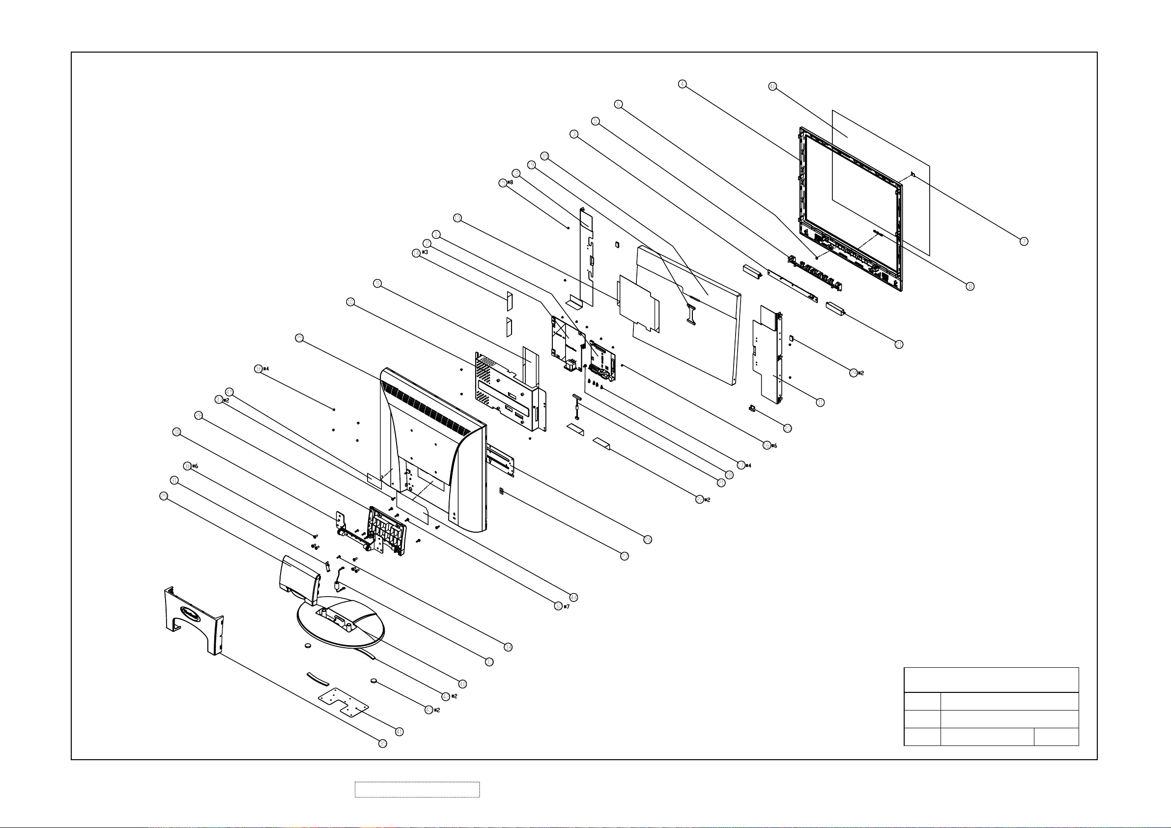
8. Exploded Diagram and Exploded Parts List
ViewSonic Corporation Confidential
43
-
Do Not Copy VA912/b-4
ViewSonic Corporation
Model
Title
Date Rev:

Rev: 1a
EXPLODED PARTS LIST (VA912-4)
ViewSonic Model Number: VS10867-1W
Serial No. Prefix: PW7
Item ViewSonic P/N Ref. P/N Description Q'ty
1 B-00004169 21L9TAMB090 L9TA M/B ASSY(RTD2523-LF) GP 1
2 B-00003993 AS05B312D00 ADP/INV,FSP043-2PI01 90~264V GP 1
3 B-00004170 23L9VABB003 L9VA BUTTON/B ASSY GP 1
4 #N/A EAL9VA01012 LCD BEZEL L9VA GP 1
5 #N/A EBL9VA01013 FUNCTION BUTTON L9VA GP 1
6 #N/A EBW0VA02015 LENS W0VA GP 1
7 M-MS-0808-9244 FEL7V004015 BIRD LOGO-10MM L7VC 1
8 M-MS-0808-9243 FEL7V003019 LOGO FRONT-VSC-38MM L7VC 1
9 #N/A FCL7TA01018 SHIELDING MYLAR L7TAGP 1
10 #N/A FAL7TA08011 SHIELDING L9VA DUAL GP 1
11 #N/A FAL9VA01012 LCD BKT-L L9VA GP 1
12 #N/A FAL9VA02019 LCD BKT-R L9VA GP 1
13 #N/A FCL7B001018 POWER BOARD MYLAR L7B GP 1
14 #N/A FCM7T004014 AL FOIL M7T GP 3
15 M-SCW-0824-6802 MM30040IBJ9 SCREW M3.0*4.0-I(NI) GP 8
16 M-SCW-0824-0814 MM30060BBJ3 SCREW M3.0*6,B(NI) GP 6
17 M-MS-0808-8986 MBLI1004018 IO NUT LI1 GP 4
18 #N/A MS35080B456 SCREW F3.5*8-B(NI)(WASHER) 1
19 CB-00002525 DD0L9VLC015 CABLE MB-LCD(30P,140MM)L9V-5 GP 1
20 CB-00004173 DDL9VABU001 CABLE MB-BUTTON(10P/10P,280MM)L9VA GP 1
21 E-00004177 DN0TE200F00 SPEAK ASSY L9VA FG-TE200 1.5W*2 GP 1
22 #N/A FCL5M005011 AL FOIL(PANEL) L5M 2
23 M-MS-0808-9247 EBL70023013 WIRE MOUNTS L70L-E GP 1
24 #N/A GAL7TA01016 RUBBER FOOT L7TA 2
25 #N/A EAL9VA02019 LCD COVER L9VA GP 1
26 #N/A FBL9VA01013 HINGE-PLATE L9VA GP 1
27 M-MS-0808-9411 FBL70008014 LOCK METAL L70B GP 1
28 #N/A EAW0VA03011 STAND-FRONT W0VA GP 1
29 #N/A EAW0VA05013 STAND-BACK W0VA GP 1
30 #N/A FAW0VA04017 HINGE ASSY W0VA GP 1
31 #N/A FBW0VA02015 CONTACT-PLATE W0VA GP 1
32 HW-00004157 MF40140IJ29 SCREW F4.0*14-I(BNI) GP 7
33 #N/A DDL9TATH107 CABLE STAND-HINGE(1P,150MM) GP 1
34 M-SCW-0824-6895 MF40080IBJ1 SCREW F4.0*8-I(NI) GP 1
35 #N/A EBL9VA02010 HINGE COVER L9VA GP 1
36 #N/A GAW0VA02014 RUBBER PLUG VESA W0VA GRAY GP 4
37 M-SCW-0824-6797 MF40080BJ29 SCREW F4.0*8-B(BNI)GP 2
38 #N/A MM40100BL61 SCREW M4*10.0-B(BNI,NYLOK) GP 6
39 #N/A EAW0VA04017 BASE W0VA GP 1
40 E-00004175 AA90ME13006 LCD(TFT)HSD 190ME13-A02(8MS) A GP 1
41 #N/A FBW0VA03011 BASE-PLATE W0VA GP 1
42 #N/A GAW0VA03011 RUBBER FOOT-C W0VA GP 2
43 #N/A GAW0VA01018 RUBBER FOOT W0VA GP 2
44 #N/A HCL9VA01014 ID LABEL L9VA GP 1
45 M-LB-0813-0745 HCL7V002011 SERIAL LABAL L7V GP 1
46 M-MS-0808-9682 JXL9V001010 LCD FILM L9V GP 1
ViewSonic Corporation Confidential
44
-
Do Not Copy VA912/b-4
ViewSonic Model Number: VS10867-1W
EXPLODED PARTS LIST (VA912b-4)
Rev: 1a
Serial No. Prefix: PW8
Item ViewSonic P/N Ref. P/N Description Q'ty
1 B-00004169 21L9TAMB090 L9TA M/B ASSY(RTD2523-LF) GP 1
2 B-00003993 AS05B312D00 ADP/INV,FSP043-2PI01 90~264V GP 1
3 B-00004170 23L9VABB003 L9VA BUTTON/B ASSY GP 1
4 #N/A EAL9VA01021 LCD BEZEL L9VA S(EAL9VA01,R3A) GP 1
5 #N/A EBL9VA01013 FUNCTION BUTTON L9VA GP 1
6 #N/A EBW0VA02015 LENS W0VA GP 1
7 M-MS-0808-9244 FEL7V004015 BIRD LOGO-10MM L7VC 1
8 M-MS-0808-9243 FEL7V003019 LOGO FRONT-VSC-38MM L7VC 1
9 #N/A FCL7TA01018 SHIELDING MYLAR L7TAGP 1
10 #N/A FAL7TA08011 SHIELDING L9VA DUAL GP 1
11 #N/A FAL9VA01012 LCD BKT-L L9VA GP 1
12 #N/A FAL9VA02019 LCD BKT-R L9VA GP 1
13 #N/A FCL7B001018 POWER BOARD MYLAR L7B GP 1
14 #N/A FCM7T004014 AL FOIL M7T GP 3
15 M-SCW-0824-6802 MM30040IBJ9 SCREW M3.0*4.0-I(NI) GP 8
16 M-SCW-0824-0814 MM30060BBJ3 SCREW M3.0*6,B(NI) GP 6
17 M-MS-0808-8986 MBLI1004018 IO NUT LI1 GP 4
18 #N/A MS35080B456 SCREW F3.5*8-B(NI)(WASHER) 1
19 CB-00002525 DD0L9VLC015 CABLE MB-LCD(30P,140MM)L9V-5 GP 1
20 CB-00004173 DDL9VABU001 CABLE MB-BUTTON(10P/10P,280MM)L9VA GP 1
21 E-00004177 DN0TE200F00 SPEAK ASSY L9VA FG-TE200 1.5W*2 GP 1
22 #N/A FCL5M005011 AL FOIL(PANEL) L5M 2
23 M-MS-0808-9247 EBL70023013 WIRE MOUNTS L70L-E GP 1
24 #N/A GAL7TA01016 RUBBER FOOT L7TA 2
25 #N/A EAL9VA02027 LCD COVER L9VA B(EAL9VA02,R3A) GP 1
26 #N/A FBL9VA01013 HINGE-PLATE L9VA GP 1
27 M-MS-0808-9411 FBL70008014 LOCK METAL L70B GP 1
28 #N/A EAW0VA03029 STAND FRONT W0VA(EAW0VA03,R3A)BK GP 1
29 #N/A EAW0VA05021 STAND-BACK W0VA(EAW0VA05,R3A)BK GP 1
30 #N/A FAW0VA04017 HINGE ASSY W0VA GP 1
31 #N/A FBW0VA02015 CONTACT-PLATE W0VA GP 1
32 HW-00004157 MF40140IJ29 SCREW F4.0*14-I(BNI) GP 7
33 #N/A DDL9TATH107 CABLE STAND-HINGE(1P,150MM) GP 1
34 M-SCW-0824-6895 MF40080IBJ1 SCREW F4.0*8-I(NI) GP 1
35 #N/A EBL9VA02028 HINGE COVER L9VA B(EBL9VA02,R3A) GP 1
36 M-MS-0808-9815 GAL9V002014 RUBBER PLUG VESA L9V(GAL9V002,REV3A) 4
37 M-SCW-0824-6797 MF40080BJ29 SCREW F4.0*8-B(BNI)GP 2
38 #N/A MM40100BL61 SCREW M4*10.0-B(BNI,NYLOK) GP 6
39 #N/A EAW0VA04025 BASE W0VA(EAW0VA04,REV3A)BK GP 1
40 E-00004175 AA90ME13006 LCD(TFT)HSD 190ME13-A02(8MS) A GP 1
41 #N/A FBW0VA03011 BASE-PLATE W0VA GP 1
42 #N/A GAW0VA03011 RUBBER FOOT-C W0VA GP 2
43 #N/A GAW0VA01018 RUBBER FOOT W0VA GP 2
44 #N/A HCL9VA01014 ID LABEL L9VA GP 1
45 M-LB-0813-0745 HCL7V002011 SERIAL LABAL L7V GP 1
46 M-MS-0808-9682 JXL9V001010 LCD FILM L9V GP 1
ViewSonic Corporation Confidential
45
-
Do Not Copy VA912/b-4

Item
ViewSonic P/N
Ref. P/N
Description
Q'ty
PACKING PARTS LIST (VA912b-4)
Item
ViewSonic P/N
Ref. P/N
Description
Q'ty
Packing for Shipping
ViewSonic Corporation Confidential
46
-
Do Not Copy VA912/b-4
ViewSonic Model Number: VS10867-1W
Rev: 1a
Serial No. Prefix: PW8
1 #N/A 1L9VAZXVS92 VA912 monitor 1
2 #N/A HBL9VA010013 END CAP (L) 1
3 P-00004180 HBL9VA02010 END CAP (R) 1
4 #N/A HGL9VA010018 USER'S MANUAL & CD 1
5 A-00003642 DM33T181004 POWER CORD 3P 1.8M 1
6 #N/A HCL9VA02013 CARTON 1
7 M-LB-0813-1042 HCL7V019011 CARTON LABEL 1
8 M-MS-0808-9158 HAL7V002019 EPE BAG 1
9 CB-00002602 DDL7VDPC005 VGA CABLE 1
10 CB-00004149 DD0L0TPC007 AUDIO CABLE 1
11 C-00004147 38W0VABS010 Base assy 1
1 #N/A 1L9VAZXVS09 VA912 monitor 1
2 #N/A HBL9VA010013 END CAP (L) 1
3 P-00004180 HBL9VA02010 END CAP (R) 1
4 #N/A HGL9VA010018 USER'S MANUAL & CD 1
5 A-PC-0106-0224 DM333181G97 POWER CORD 3P 1.8M 1
6 #N/A HCL9VA01017 CARTON 1
7 M-LB-0813-1042 HCL7V019011 CARTON LABEL 1
8 P-00004159 HAL0T002019 PE BAG 1
9 CB-00002602 DDL7VDPC005 VGA CABLE 1
10 CB-00004149 DD0L0TPC007 AUDIO CABLE 1
11 C-00004165 38W0VABS001 Base assy 1

9. Block Diagram
+3.3V
+2.5V
POWER
AIC117ADJ
AIC117ADJ
+5V
+5V
TX0+ / TX0-
Backlight
TX1+ / TX1-
TX2+ / TX2-
19"
Panel
TX3+ / TX3-
Switch
AO3415
Clock + / Clock-
BRIGHTNESS
DDC
EEPROM
+3.3V +2.5V
24LC02
Triple ADC
Interface
Digital
HSYNC , VSYNC
AR AG AB
+12V
Panel
RTD2523
Volu
24.576MHz
Mute
Audio
TDA7496L
STBY
Interface
Clock
Gen.
RST
Host
Interface
IRQ
+5V
CSZ
CPU
MTV312V64
VBRI
Keypad
INV
ON/OFF
+12V
+5V
Power Board
And Backlight
Control
Inverter
AC IN
Crystal
DVI IN
VGA IN
11.0592MHZ
EEPROM
24LC16
ViewSonic Corporation Confidential
47
-
Do Not Copy VA912/b-4

10. Schematic Diagrams
CN1 CONN 4x2-R
1
2
3
4
6
5
7
8
2
C102
12V
L3
1U/6
FUSE1
0
1
10K/6
1
2
C4
0.1u/6
3DVCC
MMST3906
C11
R8
0/6
Q3
0.1U/6
3DVCC
R10
10K/6
R14
10K/6/NC
R1,L1
C5
0.1u/6
R13 1K/6
3DVCC
VCC12
C6
220u/16V
VRMT
L32
FEB_0805
TO252 package
U1 AIC1117CY
3
VIN
+
EC2
10uF/16V
U2 AIC1117CY
2
VIN
VOUT
GND
1
VOUT
GND
1
5DVCC
3EC
C1
0.1u/6
EC1
330u/16V
5DVCC
12
3DVCC_1
10uF/16V
EC3
R175 0/6
0.1u/6
C3
共同
layout
2
4
VO
200/6 1%
R3
+
R6
330/6 1%
3
U1與U'
3DVCC
3DVCC
3AVCC1
3PVCC
3AVCC2
RTD 3DVCC
ADC_ 3AVCC
RTD 3PVCC
LVDS_3AVCC
DSUB_5V
D30
1N4148
3DVCC
D31
1N4148
4.7K/6
R143
R18 4.7K/6
C13
1U/8
Modify
Q18
MMBT3906
3
1
2
2
MMBT3906
R144
4.7K/6
3
1
3DVCC
3
Q19
1
R16
1K/6
Q4
SN7002E
2
NC/CX201209805/8
L27
CX201209805/8
L28
C100
0.1u/6
VCPU
VBRI
C101
NC/6
SOT223 package
D1
1N4148
DEL R173,R174; ADD D1
U3 AIC1117CY
3
VIN
+
10uF/16V
EC5
VOUT
GND
1
2.5DVCC_1
+
EC6
10uF/16V
R176 0/6
0.1u/6
C12
2
4
VO
R15
200/6 1%
R17
200/6 1%
2.5DVCC
2.5DVCC
RTD 2.5DVCC
ViewSonic Corporation Confidential
48
-
Do Not Copy VA912/b-4
3
34
2
2
1
1
9
9
8
1
34
2
5
1
678
9
8
9
7
6
3
34
2
2
1
1
9
9
8
1
4
5
5
678
7
6
1
4
5
5
678
7
6
3
34
2
2
1
1
9
9
8
1
4
3
5
2
5
1
678
7
6
For layout
4
5
ViewSonic Corporation
Model
POWER
Title
Date Rev:

DDC_SDA
IN-H
IN-V
DDC_SCL
VGA/NC
CN2
PAGE1 VGA
INPUT
DDC_SDA
16
11
12
13
14
15
1
6
2
7
3
8
4
9
5
10
17
RED+IN
RED-IN
GREEN+IN
GREEN-IN
BLUE+IN
BLUE-IN
DSUB_5V
PIN 10 VGA_CON
DSUB_5V
DDC_SCL
L8 FCB1608C-190T03/6
RED+IN
RED-IN
L9 FCB1608C-190T03/6
GREEN+IN
GREEN-IN
R24
75/6/F
R27
75/6/F
C17
10pF
C20
10pF
R23 100/6
R25 100/6
R26 100/6
R28 100/6
R29 100/6
C16 0.047u/6
C18 0.047u/6
C19 0.047u/6
C21 0.047u/6
C22 0.047u/6
R30
1M/6
RED+
RED-
GREEN+
GREEN-
SOGIN
DAN217K
RED+IN
IN-H
GND
IN-H
DDC_SCL
D7
3
RED-IN
GREEN-IN
BLUE-IN
ADC_VCC
2
1
2
D10
1
GREEN+IN
IN-V
Z5.6
25
26
DVI-D/NC
11
13
DAN217K
CN4
RX2-
RX2+
GND
RX4-
RX4+
RX1-
RX1+
GND
RX3-
RX3+
GND
RX0-
RX0+
GND
RX5-
RX5+
GND
RXC+
RXC-
CN3
1
+
+
3
+
+
5
+
+
7
+
+
9
+
+
+
+
+
+
NC/VGA INPUT
D8
3
1
2
3
4
5
6
SCL
7
SDA
8
VS
9
10
11
12
13
14
5V
15
16
HP
17
18
19
20
21
22
23
24
2
1
2
4
6
8
10
12
14
2
1
D11
DDC_SDA
Z5.6
RED+IN
GREEN+IN
BLUE+IN
GND
IN-V
DDC_SDA
DSUB_5V
DAN217K
BLUE+IN
R48 10K/6
C31
1U/6NC
2
1
D9
3
D12
Z5.6
DDC2_SCL
DDC2_SDA
2
1
2
1
DDC_SCL
D24
Z5.6
2
D13
Z5.6
1
Bus_Power
C30
0.1U/6
L10 FCB1608C-190T03
BLUE+IN
BLUE-IN
R32
75/6/F
IN-H
C24
10pF
L31 FCM1608C-300T06/6
IN-V
R37
2K/6
R155 0
R156 0
R157 0
R158 0
R159 0
R160 0
R161 0
R162 0
D18
D20
D25
Z5.6
Z5.6
Z5.6
2
D19
Z5.6
1
2
D21
Z5.6
1
2
D26
Z5.6
1
2
D27
1
Z5.6
2
D28
Z5.6
1
2
1
2
1
2
1
R31 100/6
R33 100/6
R34 100/6
R35
2K/6
R36 100/6
TX2TX2+
TX1TX1+
TX0TX0+
TXC+
TXC-
C26
22P/6
VGAVS
C28
22P/6
C23 0.047u/6
C25 0.047u/6
VGAHS
BLUE+
BLUE-
2
D34
Z3.3V
1
2
D35
Z3.3V
1
AHS
AVS
C29 0.1U/6
U5
1
NC
2
NC
3
NC
4
VSS SDA
M24LC02
Bus_Power
VCC
VCLK
SCK
3DVCC
D17
BAT54C-GS08
R44
8
7
6
5
2K/6
2
D22
Z5.6/NC
1
R45
2K/6
R46 100/6
R47 100/6
2
D23
Z5.6/NC
1
3DVCC
DDC2_SCL
DDC2_SDA
ViewSonic Corporation
Model
VGA AND DVI INPUT
Title
ViewSonic Corporation Confidential
49
-
Do Not Copy VA912/b-4
Date Rev:

3DVCC
3DVCC
L12
FEB_0805
C34
10uF/16V
C35
0.1u/6
C36
0.1u/6
C37
0.1u/6
C38
0.1u/6
C39
0.1u/6
C40
0.1u/6
C41
0.1u/6
C42
0.1u/6
C43
0.1u/6
C44
0.1u/6
C45
0.1u/6
C46
10uF/16V
L13 FEB_0805
R2.5DVCCR3DVCC
2.5DVCC
C47
0.1u/6
2.5DVCC
TMDS_AVCC
R57
NC
R58
4.7K/6
3AVCC1
3PVCC
3AVCC2
3PVCC
R54
4.7K/6
R55
4.7K/6/NC
3AVCC2 TMDS_AVCC
L15 FEB_0805
C54
C60
0.1u/6
0.1u/6
22uF/16V
L19 FEB_0805
C33 22pF/6
C48 22pF/6
L14 FEB_0805
C50
0.1u/6
10uF/16V
C49
PLL_GND
+
C53
ADC_VCC3AVCC1
+
C59
22uF/16V
ADC_GND
C43.C44.C45
XO
R53
NC
C61
Y1
24.576MHz
XI
+
0.1u/6
C51
0.1u/6
C52
R56 1K/6 R68
TX2+
TX2TX1+
TX1TX0+
TX0TXC+
TXC-
RX2P
RX2N
RX1P
RX1N
RX0P
RX0N
RXCP
RXCN
Near to Chip
C55
0.1u/6
0.1u/6
BLUE+
BLUE-
SOGIN
GREEN+
GREEN-
RED+
RED-
0.1u/6
C62
盡量靠近
C56
0.1u/6
C63
0.1u/6
C57
C64 0.1u/6
0.1u/6
IC
AHS
AVS
0.1u/6
C58
B+
BSOG
G+
GR+
R-
AHS
AVS
RTD_SCLK
RTD_SDO/SDI
RTD_SCSB
DDC_SDA
DDC_SCL
XO
XI
SDIO1
SDIO2
SDIO3
RESET
U6
1
XO
2
XI
4
DPLL_VDD
5
APLL_VDD
3
DPLL_GND
8
APLL_GND
6
PLL_TEST1
7
PLL_TEST2
9
TMDS_TST/PWM1
12
EXT_RES
14
RX2P
15
RX2N
17
RX1P
18
RX1N
20
RX0P
21
RX0N
23
RXCP
24
RXCN
11
TMDS_VDD
13
TMDS_VDD
19
TMDS_VDD
26
TMDS_VDD
TMDS_GND
10
16
TMDS_GND
22
TMDS_GND
25
TMDS_GND
B+
30
B-
31
SOG/ADC_TEST
33
34
G+
G-
35
R+
37
R-
38
ADC_VDD
29
36
ADC_VDD
ADC_VDD
41
ADC_REFIO
28
ADC_GND
27
ADC_GND
32
ADC_GND
39
ADC_GND
40
AHS
42
AVS
43
R66 100/6
120
3.3V Ground
96
109
3.3V Ground
SCLK
50
3.3V Ground
SDIO[0]
54
84
53
3.3V Ground
TCON[4]/SDIO[1]
72
3.3V Ground
TCON[3]/SDIO2]
52
57
51
NCR71
48
3.3V Ground
TCON[2]/SDIO[3]/PWM2
3.3V Ground
SCSB
RESET#
56
111
NCR72
110
95
83
121
3.3V Power
3.3V Power
3.3V Power
3.3V Power
RTD2523
DDCSDA
47
58
71
3.3V Power
3.3V Power
DDCSDA2
DDCSCL
46
125
49
3.3V Power
DDCSCL2
126
127
2.5V Power
98
45
69
2.5V Power
2.5V Power
TCON[11]/V[0]
TCON[10]/V[1]
115
114
2.5V Power
TCON[9]/V[2]
TCON[8]/V[3]
117
116
70
44
97
128
TCON[12]/COUT/PWM2
TCON[13]/COUT/PWM2
2.5V Ground
2.5V Ground
2.5V Ground
2.5V Ground
TCON[0]/VCLK
TCON[1]/V[7]
TCON[7]/V[4]
TCON[6]/V[5]
TCON[5]/V[6]
122
119
118
123
124
PWM0/REFCLK
AR1N
AR1P/TCON[0]
AR2N/TCON[1]
AR2P/TCON[5]
AR3N/TCON[6]
AR3P/TCON[7]
AG1N/TCON[8]
AG1P/TCON[9]
AG2N/TCON[10]
AG2P/TCON[11]
BG3N
BG3P
BCLKN
BCLKP
BB1N
BB1P
BB2N
BB2P
BB3N
BB3P
AG3N/TEAN
AG3P/TEAP
ACLKN/TEBN
ACLKP/TEBP
AB1N/TECN
AB1P/TECP
AB2N/TECLKN
AB2P/TECLKP
AB3N/TEDN
AB3P/TEDP
BR1N/TOAN
BR1P/TOAP
BR2N/TOBN
BR2P/TOBP
BR3N/TOCN
BR3P/TOCP
BG1N/TOCLKN
BG1P/TOCLKP
BG2N/TODN
BG2P/TODP
55
107
106
105
104
103
102
101
100
99
68
67
66
65
64
63
62
61
60
59
94
93
92
91
90
89
88
77
76
75
74
73
113
112
87
86
85
82
81
80
79
78
108
RXEIN0RXEIN0+
RXEIN1RXEIN1+
RXEIN2-
RXEIN2+
RXECKINRXECKIN+
RXEIN3-
RXEIN3+
RXOIN0-
RXOIN0+
RXOIN1-
RXOIN1+
RXOIN2-
RXOIN2+
RXOCKINRXOCKIN+
RXOIN3-
RXOIN3+
VBRI
VOLUME
5DVCC
5DVCC
L22
FEB_1206
DGND
VCC12
L21
NC
R67
82K/6
R70
82K/6
3
1
GND
PANEL_5_12VCC
Q9
DTC144EUA
2
RXEIN0RXEIN2-
DGND
RXECKINRXEIN3RXOIN0DGND
RXOIN1RXOIN2RXOCKINRXOIN3-
0/6R177
Q8 SI2301DS
1
C67
2200P/6
1
3
5
7
9
11
13
15
17
19
21
23
25
27
29
2
PANEL_PW12
CN5
1
2
3
4
5
6
7
8
9
10
11
12
13
14
15
16
17
18
19
20
21
22
23
24
25
26
27
28
29
30
1841 30P
3
C68
2200P/6
RXEIN0+
2
RXEIN1+RXEIN1-
4
RXEIN2+
6
DGND
8
RXECKIN+
10
RXEIN3+
12
RXOIN0+
14
DGND
16
RXOIN1+
18
RXOIN2+
20
RXOCKIN+
22
RXOIN3+
24
26
PANEL_5_12VCC
28
PANEL_5_12VCC
30
G
0/6R178
PANEL_5_12VCC
10K/6
D
3
DGND
C69
0.1U/6
S12
PANEL_5_12VCC
C70
100U/16V
ViewSonic Corporation Confidential
50
-
Do Not Copy VA912/b-4
ViewSonic Corporation
Model
Title
Date Rev:
RTD2523

3AVCC1
RESET
NC/ 1N4148
3AVCC1
D32
R147
4.7K/6
R165
NC/100K/6
C103
NC/1U/16V
2
2N3906
Q13
3DVCC
1
3
1
Q12
2N3906
2
3
VCPU
1
Q20
2
3
R166
0/6
NC/2N3906
2
Reset circuit
1
D33
NC/DAN202U
3
VCPU
C86
NC/1U/16V
R106
NC/82K/6
R78
10K/6
LED_G
LED_R
C84
+
22uF/16V
3DVCC
R79
10K/6
R82 4.7K/6
R93 4.7K/6
VCPU
C85
0.1u/6
C
B
3DVCC
MENU
SEL
PWR
DOWN
UP
RIGHT
LEFT
Junction from
A change to B
VCPU
E
33K/6
33K/6
R87
R88
0.1U/6
0.1U/6
C76
C77
33K/6
33K/6
R90
R89
0.1U/6
0.1U/6
C78
C79
33K/6
33K/6
R91
0.1U/6
C80
33K/6
R84
R85
0.1U/6
0.1U/6
C82
C81
less R94 to CN6 pin 11
R95 1K/6
R96 1K/6
R97 1K/6
R98 1K/6
R99 1K/6
R100 1K/6
R101 1K/6
R102 220/6
R103 220/6
R101,R103 net swap
CN6
10
9
8
7
6
5
4
3
2
1
4501-10-10P-R
TO BUTTON BOARD
90° E&T
4607-11Pin
VCPU
1
2
C75
0.1U/6
4.7K/6
R170
U8
1
A0
2
A1
3
A2
4
VSS SI
24LC16
PARAMETER
EEPROM
R171
4.7K/6
VCC
WP
SCK
R172
4.7K/6
8
7
6
5
VCPU
R180
NC
KEY1
KEY2
KEY3
R80
2K/6
R81
2K/6
R83 100/6
R92 100/6
PANEL_PW12
R179
2K/6
WP_EE
MUTE
STBY
C87 10pF/6
C88 10pF/6
VCPU
R142 NC
IICSCL
IICSDA
LED_R
LED_G
KEY1
KEY2
KEY3
Y2
11.0592MHz
PWR_SEL
R41
6.8K/6
R38
2K/6
VCC12
I1
12
X1
11
X2
7
RESET
19
INT0/P3.2
14
ISCL/P3.5/T1
13
ISDA/P3.4/T0
27
P6.0/AD0
26
P6.1/AD1
16
P6.2
9
P6.3
30
P6.4
31
P6.5
32
P6.6
33
P6.7
MTV312M64
6
NC
5
4
NC
VDD3
44
43
8
VCCVSS
VSYNC
HSYNC
DA8/HLFHO
DA9/HALFV
P3.1/TXD
P3.0/RXD
10
P5.0
P5.1
P5.2
P5.3
P5.4
P5.5
P5.6
P1.0
P1.1
P1.2
P1.3
P1.4
P1.5
P1.6
P1.7
DA7
P4.0
P4.1
P4.2
R163
4.7K/6
R164 22
3
2
1
42
41
40
34
39
38
17
18
20
21
22
23
24
25
35
36
37
15
28
29
KEY1
KEY2
KEY3
R181 22
2
1
R39 4.7K/6
R40 4.7K/6
4
3
R124 100/6
R125 100/6
JP3
56
MENU
SEL
PWR
UP
DOWN
RIGHT
LEFT
WP_EE
VCPU
AVS
VRMT
R109 4.7K/6
R108 4.7K/6
R110
4.7K/6
VCPU
R111
4.7K/6
TxD
RxD
R112
NC
R113
NC
VCPU
R114
4.7K/6
DDC_SDA
DDC_SCL
R115
4.7K/6
5DVCC
SDIO1
SDIO2
SDIO3
RTD_SCLK
RTD_SCSB
JP1
1
2
3
4
HEADER 4
2004/12/28
ViewSonic Corporation Confidential
51
-
Do Not Copy VA912/b-4
2004/12/28
ViewSonic Corporation
Model
Title
Date Rev:
MCU & BUTTON
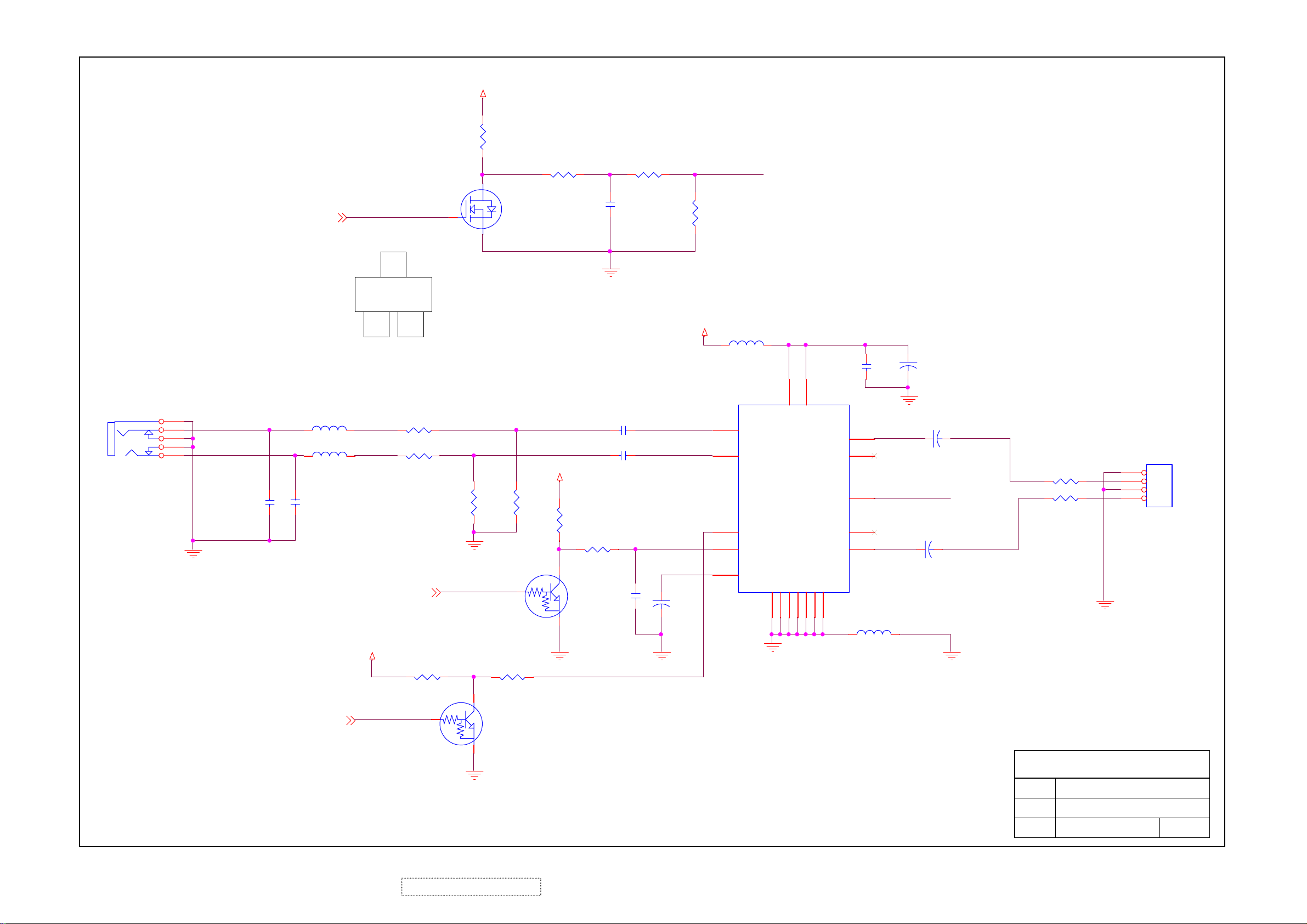
VCC12
R128
1K/6
PC AUDIO-IN
J3
ZD005D100
1
5
4
3
2
Z0412
AGND
L_LINE
R_LINE
VOLUME
L25 600/CX601T02001
1
1
L26 600/CX601T02001
220P/6
220P/6
C96
C95
2
2
3BC
R133 100/6
Z0416
VCC12
2
12
E
R132 100/6
MUTE
R140 10K/6
MUTE
3
1
R135
20K/6
AGND
R141 10K/6
R129 10K/6
SN7002E
Q15
LIN_PCZ0415
RIN_PC
20K/6
R136
2
R130 10K/6
1U/8
C89
AGND
C92 0.47U/8
C94 0.47U/8
VCC12
R138
10K/6
R139 10K/6
3
Q16
0.1U/8
DTC144EUA
1
AGND AGND
C98
C99
330U/16V
R131 3.9K/6
VCC12
VOL
L24
4
9
11
12
10
TDA7496L
BEAD/1206
U9
INL
INR VAROUT_L
STBY
SVR
GND
1
AGND
GND
2
15
VS
GND
3
16
VS
OUTL
VOLUME
VAROUR_R
OUTRMUTE
GND
GND
GND
18
20
19
13
GND
C90
0.1U/6
AGND
17
5
6
7
14
L23 BEAD/1206
C93
C97
VOL
C91
330U/16V
330U/16V
330U/16V
SPKOUTL
SPKOUTR
R134 CX201209805/8
R137 CX201209805/8
AGND
JP2
1
2
3
4
4606-04-04P-R
SPEAKER OUT
STBY
STBY
2
ViewSonic Corporation Confidential
52
3
Q17
DTC144EUA
1
AGND
-
Do Not Copy VA912/b-4
ViewSonic Corporation
Model
Title
Date Rev:
AUDIO

11. PCB Layout Diagrams
MB TOP
ViewSonic Corporation Confidential
53
-
Do Not Copy VA912/b-4

ViewSonic Corporation Confidential
54
-
Do Not Copy VA912/b-4

*Readers Response*
Dear Readers:
Thank you in advance for your feedback on our Service Manual, which allows continuous improvement
of our products. We would appreciate your completion of the Assessment Matrix below, for return to
ViewSonic Corporation.
A. What do you think about the content of this Service Manual?
Assessment
1.
Precautions and Safety Notices
2. Specification
Front Panel Function Control Description
3.
4. Circuit Description
5.
Adjustment Procedure
6. Troubleshooting Flow Chart
7. Recommended Spare Parts List
8. Exploded Diagram and Exploded Parts List
9. Block Diagram
10. Schematic Diagrams
11. PCB Layout Diagrams
tinU riaF daB
dooGtnellecxE
B. Are you satisfied with this Service Manual?
metI tnellecxE dooG riaF daB
.1
Service Manual Content
.2
Service Manual Layout
.3
The form and listing
C. Do you have any other opinions or suggestions regarding this service manual?
Readers basic data:
Name: Title:
Company:
Add.:
Tel:
E-mail:
After completing this form, please return it to ViewSonic Quality Assurance
1-909-839-7943.
(marc.maupin@viewsonic.com)
You may also e-mail any suggestions to the Director, Quality Systems & Processes
Fax:
in the USA at facsimile
ViewSonic Corporation Confidential
55
-
Do Not Copy VA912/b-4
 Loading...