

Page 1

Service Manual
ViewSonic N3260w-1NT
N3760w-1NT
N4060w-1NT
N3260wb-1NT
N3760wb-1NT
Model No. VS10847-NT-1P
VS10848-NT-1P
VS10846-NT-1P
32” 37” 40” LCD TV
(N3260w_N3760w_N4060w_N3260wb_N3760wb-1NT_SM_Rev.1c_Nov.2006)
ViewSonic® 381 Brea Canyon Road, Walnut, California 91789 USA - (800) 888-8583
Page 2
ViewSonic Corporation Confidential - Do Not Copy
N3260w_N3760w_N4060w
N3260wb_N3760wb-1NT
1
Copyright
Copyright © 2006 by ViewSonic Corporation. All rights reserved. No part of this publication may be
reproduced, transmitted, transcribed, stored in a retrieval system, or translated into any language or
computer language, in any form or by any means, electronic, mechanical, magnetic, optical, chemical,
manual or otherwise, without the prior written permission of ViewSonic Corporation.
Disclaimer
ViewSonic makes no representations or warranties, either expressed or implied, with respect to the contents
hereof and specifically disclaims any warranty of merchantability or fitness for any particular purpose. Further,
ViewSonic reserves the right to revise this publication and to make changes from time to time in the contents
hereof without obligation of ViewSonic to notify any person of such revision or changes.
Trademarks
Optiquest is a registered trademark of ViewSonic Corporation.
ViewSonic is a registered trademark of ViewSonic Corporation.
All other trademarks used within this document are the property of their respective owners.
Revision History
Revision SM Editing Date ECR Number Description of Changes Editor
1a 2006/04/25 Initial Release Sophia Kao
N3760wb-NT's RSPL and BOM.
1b 2006/07/04
Add two models, N3260wb-NT and
Sophia Kao
Sophia Kao
1c 2006/11/14
Add Assembly and disassembly procedure
on SM.
Page 3

TABLE OF CONTENTS
1. Precautions and Safety Notices 3
2. Specification 6
3. Front Panel Function Control Description 8
4. Circuit Description 9
5. Adjustment Procedure 16
6. Trouble Shooting Flow Chart 23
7. Block Diagram 27
8. PCB Layout Diagrams 28
9. Schematic Diagrams 32
10. Exploded Diagram and Exploded Parts List 47
11. Assembly and disassembly procedure 53
ViewSonic Corporation Confidential - Do Not Copy
2
N3260w_N3760w_N4060w
12. Recommended Spare Parts List 56
N3260wb_N3760wb-1NT
Page 4

1. Precautions and Safety Notices
All rights reserved. No part of this publication may be reproduced, transmitted, transcribed,
stored in a retrieval system or translated into any language in any form or by any means,
electronic, mechanical, magnetic, optical, chemical, manual, or otherwise, without the prior
permission of the company.
Disclaimer
We make no representations or warranties, either expressed or implied, with respect to the
contents of this document, and specifically disclaims any warranties, merchantability or fitness
for any particular purpose. Further, reserves the right to revise this publication and make
changes in the contents without obligation to notify any person of such revision or change.
All rights reserved
VGA and XGA are registered trademarks of International Business Machines Co. Inc.
Product safety notice
Many electrical and mechanical parts in this product include specific, safety related
characteristics. These characteristics may not be immediately obvious by visual inspection and
the protection these components offer can not necessarily be obtained using replacement
components with the same voltage or power ratings.
offer can not necessarily be obtained using replacement components with the same voltage or
power ratings. Electrical components having such features are identified by shading on the
schematic diagram and in the parts list. Before replacing components, read the parts list in this
manual thoroughly.
The use of substitute parts which do not have the same safety characteristics as those indicated
in the parts list may cause electrical shock, fire, x-ray emissions, or other hazards.
Service notes
1. When replacing circuit boards or components, clamp the lead wires to the terminals before
soldering.
2. When replacing a high power resistor (oxide metal film resistor) on a circuit board, keep the
resistor at least 10 mm (0.5-inch) from the circuit board.
3. Keep leads and wires away from high voltage and high temperature components.
4. If any fuse in the product is blown, replace it only with the correct fuse specified in the parts
list.
Handling of broken glass and liquid crystal leakage
If the LCD is damaged, liquid crystal leakage may occur and the glass may shatter into small pieces. Do
not touch the broken glass or liquid crystal which is toxic. In addition to possible cuts resulting from
broken glass, toxic leakage may cause skin irritation or poisoning. If liquid crystal enters your eyes or
mouth, you should immediately rinse with clean water and consult a doctor.
Important safety information
1. Read all these instructions.
ViewSonic Corporation Confidential - Do Not Copy
3
N3260w_N3760w_N4060w
N3260wb_N3760wb-1NT
Page 5

2. Save these instructions for later use.
3. Unplug this television set from the wall outlet before cleaning.
4. Do not use accessories not recommended in the user manual as they may damage the product.
5. Do not use this product in wet locations such as near a bathtub, washbowl, kitchen sink, laundry
tub, swimming pool, or in a wet basement
6. Do not place this product on an unstable cart, stand, or table. The television receiver may fall
and causeserious injury as well as possibly damaging the product. Use only with a cart or
stand recommended serious injury as well as possibly damaging the product. Use only with a
cart or stand recommended instructions and only use a mounting kit as recommended by the
manufacturer.
7. Blocking the ventilation holes can cause overheating and fire. Take care not to block any
ventilation holes when siting the television close to walls or other objects. Never install this
product in a closed cabinet or bookcase unless sufficient ventilation is provided.
8. This television should be operated using only the type of power source indicated on the label
and in the user manual. If you are unsure what your home power supply is, you should
consult the Power Company or talk to your television dealer.
9. This television is equipped with a plug designed to fit only one way in the power socket. The
earth pin is an important safety feature of the plug. If the plug does not fit your outlets or your
outlets do not include a hole for the earth pin, you should consult a qualified electrician about
replacing the socket.
10. Do not rest anything on the power cord and do not allow the power cord to lie in a position
where it is likely to be stepped on or tripped over.
11. Follow all warnings and instructions marked on the television receiver.
12. During thunderstorms and when the television is unused for extended periods of time, you
should unplug the power cord from the outlet and disconnect the antenna.
13. External antenna systems should be sited away from overhead power lines and away from
electrical circuits. Extreme caution should be exercised when erecting an outside antenna.
Touching overhead power cables can be fatal.
14. Do not overload power outlets or extension cords as fire or electric shock can result.
15. Never push anything into the television through the ventilation slots as they may come into
contact with high voltage elements of the device and cause electric shock or fire. Take care
never to spill liquids into the product.
16. Servicing of this product should only be carried out by qualified service technicians.
17. Unplug this product from the power source and consult a qualified service technician in the
following
cases:
• The power cord is damaged or frayed.
• Liquid is spilled into the television.
• The television is exposed to rain or water.
• The television does not operate as the user manual describes. In this case, use only
ViewSonic Corporation Confidential - Do Not Copy
4
N3260w_N3760w_N4060w
N3260wb_N3760wb-1NT
Page 6

the controls covered by the operating instructions. Improper adjustment of this equipment
using controls not covered in the user manual may result in damage to the product that may
require extensive work by qualified technicians to rectify.
• The television or cabinet is damaged.
• The television shows a change in performance that indicates a need for servicing.
18. When replacement parts are used, ensure that the technician uses only parts recommended
by the manufacturer. Unauthorised replacement parts may cause a fire or electric shock.
19. After servicing, ensure that the technician performs routine safety checks to determine
whether the television is in a safe operating condition.
20. When moving this equipment, care should be taken to prevent damage due to dropping,
falling or impact.
Introduction
This service manual covers the LCD TV and is intended for the use of qualified service
engineers only. Service and repair of this product by unqualified persons may result in
permanent damage to the product or personal injury and should not be attempted.
This manual includes:
.A block diagram of the LCD TV
.An explanation of theory of operation
.An explanation of the service mode to enable you to adjust the internal settings
.A step by step guide to assembly and disassembly of the product
.A complete parts list for the product
.An exploded diagram of the product
.Pictures of the printed circuit boards
ViewSonic Corporation Confidential - Do Not Copy
5
N3260w_N3760w_N4060w
N3260wb_N3760wb-1NT
Page 7

2. Specification
Panel Type 32” (full 31.5” viewable diagonal area)
37” (full 37.02” viewable diagonal area)
40” (full 39.9” viewable diagonal area)
Active Matrix Wide-XGA, 136
6 x 768
Color Anti-reflective coating + Anti-glare coating
Viewing angles 32” 170° (H) / 170° (V)
37” 176° (H) / 176° (V)
40” 170° (H) / 170° (V)
Input signal Video VGA input * 1
TV system antenna
Composite Video input * 2
S-Video * 2
Component Video * 2 (YCbCr, YPbPr)
HDMI * 1
Audio Audio input (3.5 For V
GA*1)
Audio output * 1
Compatibility PC Up to 1360 x 768 Non-interlaced
Macintosh1 Up to 832 x 624 Non-interlaced
Resolution Supported 1280 x 1024 @ 60 Hz*
1024 x 768 @ 60/75 Hz
1280 x 768 @ 60 Hz
1280 x 720 @ 60 Hz
1360 x 768 @ 60 Hz (it is the PC reference mode)
832 x 624 @ 75 Hz (Mac)
800 x 600 @ 60/75 Hz
640 x 480 @ 60/75 Hz
720 x 400 @ 70 Hz
* is not supported at HDMI status.(PIP/POP)
Speaker Output 10 W + 10 W
Power Voltage 32”:190W 110V VAC ,50/60Hz (auto switch)
37”:220W 110-240 ,50/60Hz (auto switch)
ViewSonic Corporation Confidential - Do Not Copy
6
N3260w_N3760w_N4060w
N3260wb_N3760wb-1NT
Page 8

40”:260W 110-240 ,50/60Hz (auto switch)
Operating Temperature 0°C to 40°C (32°F to 104°F)
Conditions Humidity 10% to 85% (no condensation)
Altitude To 3000 meters
Storage conditions Temperature -20°C to 60°C (-4°F to 140°F)
Humidity 10% to 85% (no condensation)
Altitude To 12,000 meters
Dimensions Physical 32” : 820 mm (W) x 650 mm (H) x 230 mm (D)
32.3” (W) x 25.6” (H) x 9.1 “(D)
37” : 960 mm (W) x 730 mm (H) x 280 mm (D)
37.8” (W) x 28.7” (H) x 11” (D)
40” : 1015 mm (W) x 755 mm (H) x 280 mm (D)
40.0 ”(W) x 29.7” (H) x 11” (D)
Package 32” : 960mm (W) x 780 mm (H) x 320 mm (D)
37.8” (W) x 30.7” (H) x 12.6 “(D)
37” :1130 mm (W) x 870 mm (H) x 370 mm (D)
44.5” (W) x 34.3” (H) x 14.6” (D)
40” : 1145 mm (W) x 910 mm (H) x 370 mm (D)
45.1 (W) x 35.8” (H) x 14.6” (D)
Weight Net 32” : 22 kg (48.5 lb.)
37” : 31 kg (68.3 lb.)
40” : 33 kg (72.7 lb.)
Gross 32” : 26.5 kg (58.4 lb.)
37” : 38.5 kg (84.9 lb.)
40” : 40.0 kg (88.1 lb.)
Regulations BSMI
Power saving modes Stand by <1.5 W (Red LED)
Preset Timing Mode (Pre-adjusted to VESA 1360 x 768 at 60 Hz)
War nin g : Do not set the graphics card in you computer to exceed these refresh rates. Doing so may result in permanent
damage to the LCD.
Note : Product specifications are subject to change without notice.
ViewSonic Corporation Confidential - Do Not Copy
7
N3260w_N3760w_N4060w
N3260wb_N3760wb-1NT
Page 9
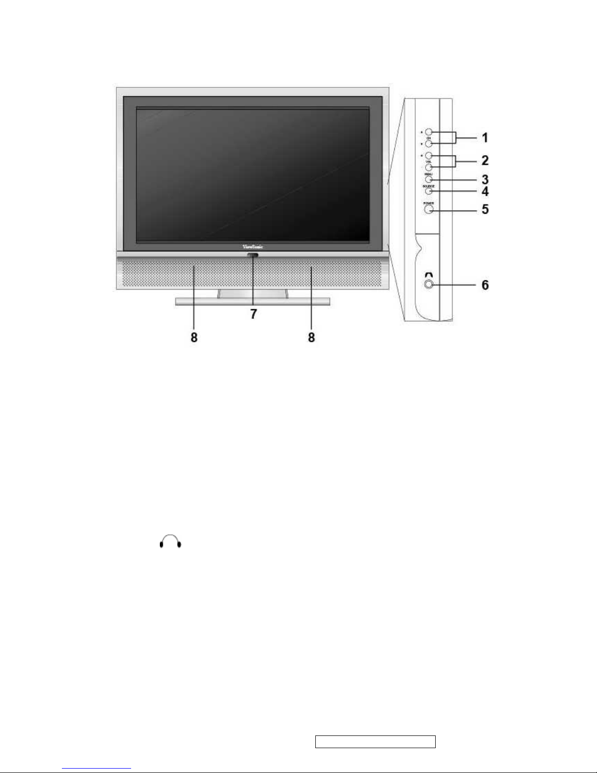
3. Front Panel Function Control Description
1. CH ▲/ ▼
Changes the channel.
2. VOL +/–
Used for changing the volume.
3. MENU
Display menu screen
4. SOURCE
Switch between display input sources.
5. POWER
Turns the TV on and off. A green light indicates that TV is on and red that it is off.
6. EARPHONE
Used for connecting headphones to the TV.
7. Power indicator LED
Green shall apply during all operational states(ie.with image preaent).
Orange shall apply DPMS State for RGB/DVI.
Red shall apply when the product in stand-by mode. (DPMS state only in PC mode.)
8. SPEAKERS
Audio output.
ViewSonic Corporation Confidential - Do Not Copy
8
N3260w_N3760w_N4060w
N3260wb_N3760wb-1NT
Page 10
4. Circuit Description
Power Circuit:
Exchanged Power Model provide this machine 3 batch power: +12V, +5V and +24V. +5V is Stand-By power, provide
every circuits in main board needed power with +12V.+24 is back light power.
A.
Cold-Start Mode
:
z Exchanged Power Model (+12V, +5V), via power1 jack transmits voltage to digital main board.
z When connect with AC110V, exchanged power produce +5V voltage immediately (circuit mark
5V_SB) and provide CPU U22 the needed stand-by voltage to turn on the machine
z This machine is in Stand-By Mode now.
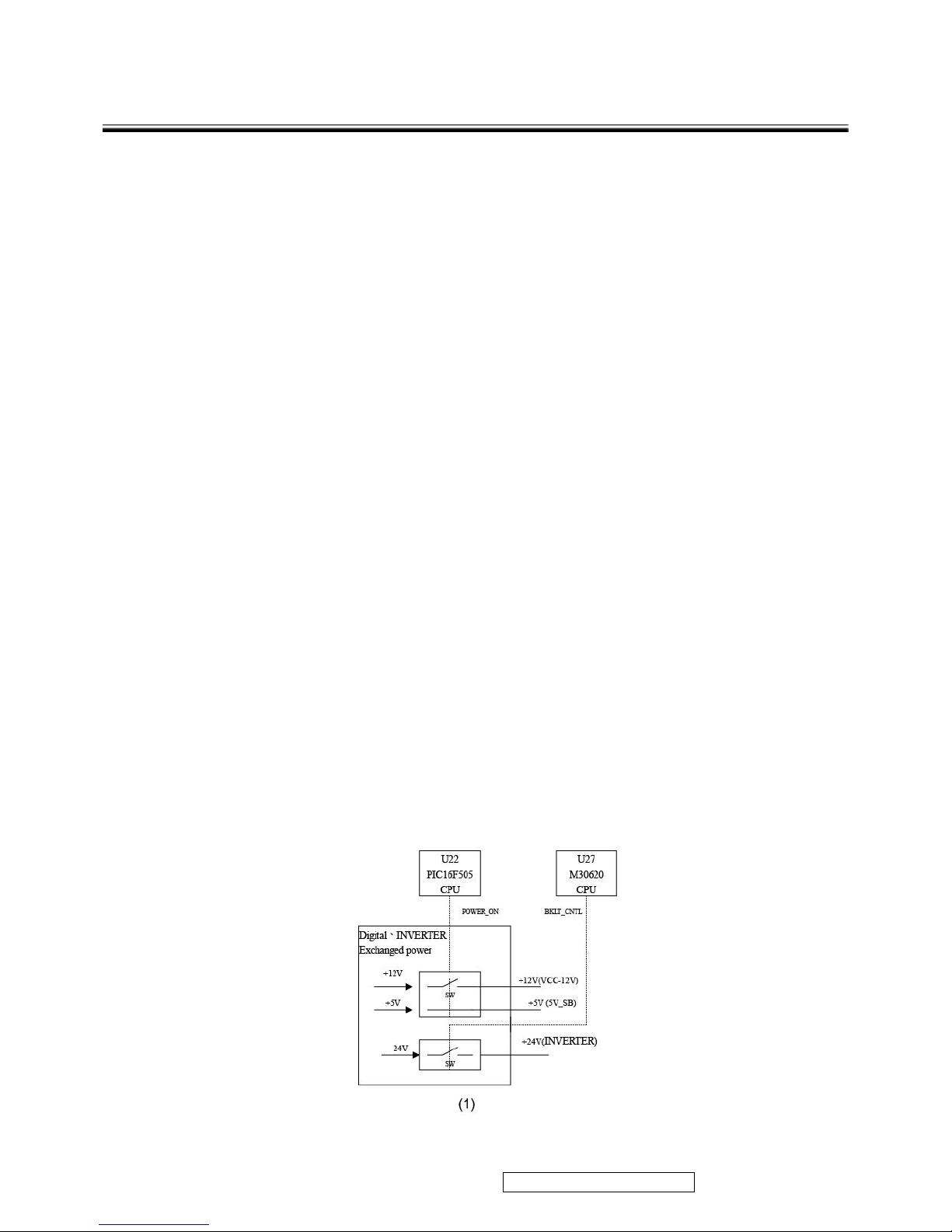
B.
Stand-By Mode(+5V)
:
z In Stand-By Mode, Exchanged Power Model provides +5V voltage (circuit mark 5V_SB) and provides
the needed power to CPU U22 PIC 16F505.
z When this machine is in Stand-By mode, only U22- PIC16F505 keep working, so the system can
assure the consumption power is < 1.5W in Stand-by Mode.
z The Block Diagram 1 shows Stand-By Mode
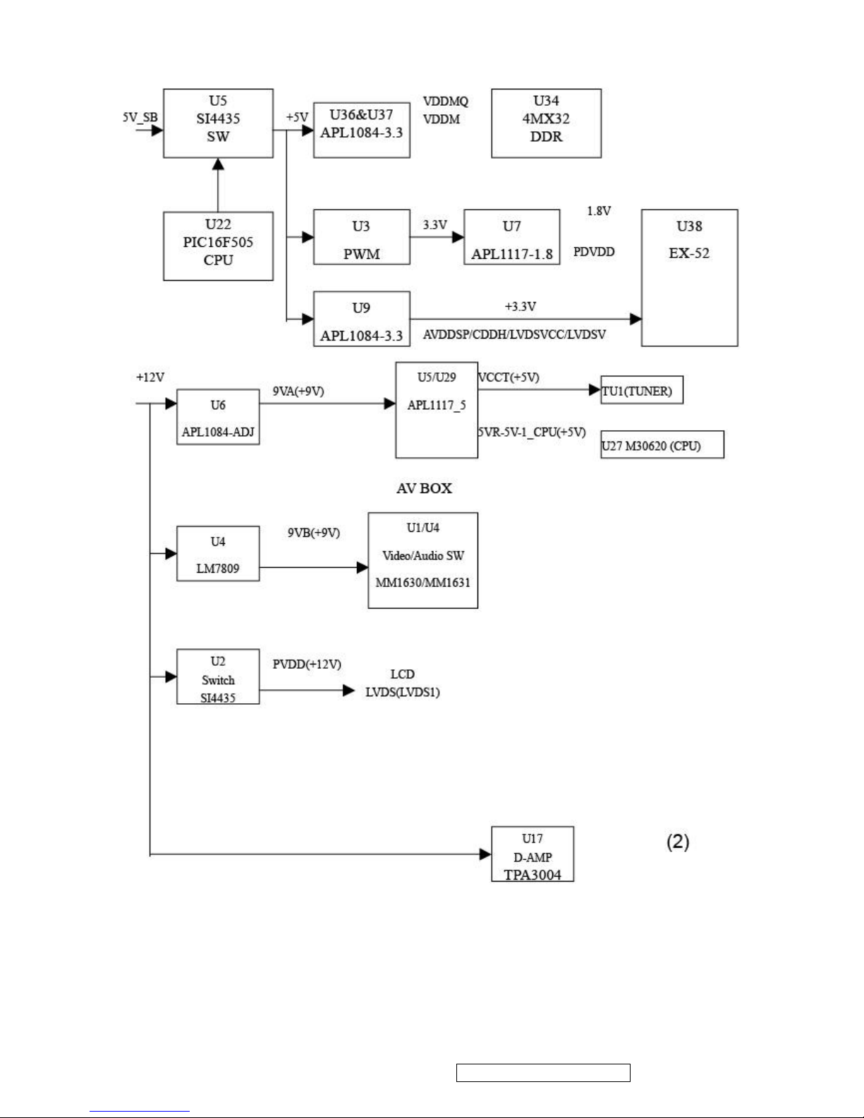
C. Power ON Mode(+5V ,+12V)
z When the system receives the start order by Power Key of the remote control or Power ON/OFF of
the control panel, it will process the following action
z The system hands over CPU’s masterdom from CPU U22CPU to U27 M30620 .
z When exchanged power receives the start order by CPU U22, (signal mark POWER_ON), via Q3
MMBT3904 to control Exchanged Power Model provides +12V voltage (signal mark VCC_12V).
Every batches of digital board circuit would be able to process Power ON procedure.
z After every batches of digital board process Power ON procedure,U29 M30620 via BKLT_CNTL to
control circuit and light the back light.
z The Block Diagram 2 shows the voltage of Power ON Mode and IC.
ViewSonic Corporation Confidential - Do Not Copy
9
N3260w_N3760w_N4060w
N3260wb_N3760wb-1NT
Page 11
ViewSonic Corporation Confidential - Do Not Copy
10
N3260w_N3760w_N4060w
N3260wb_N3760wb-1NT
Page 12
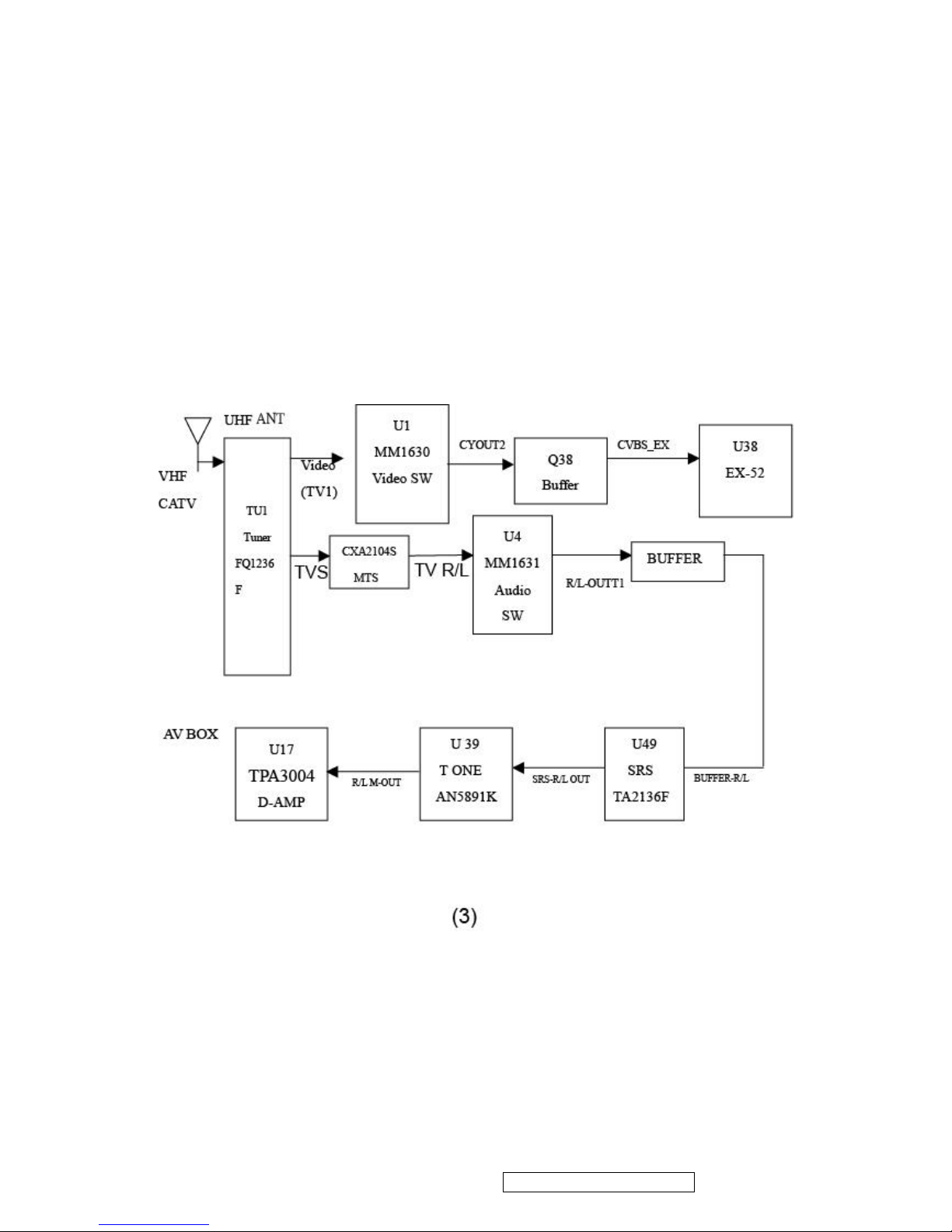
Antenna Circuit:
• Tuner FQ1236F receive the signal coming from CATV or antenna RF NTSC signal and demodulate image
composite signal (signal mark TV 1) and audio medium frequency signal (signal mark SIF1).
• Image composite signal (signal mark TV 1)
• Image composite signal enter Video SW IC AV BOXU1 MM1630 PIN 17 and switch with other input
signals in U1 inner switch circute .Output from PIN 60 (signal mark CYOUT2) than via Q38 Video buffer (signal
mark CVBS_EX) and enter U38 Scaler IC EX-52 (Pin 242) directly. Switches with other input signals in
U38 inner switch circute.
• Audio medium frequency signal (signal mark TV-S), transmits U3 CAX2104S to demodulate audio IF and
stereo.Then switches signal source with other Audio Source in U4 MM1631 Audio S/W.PIN 29,30 outputs via
Q25,Q26 Audio buffer to U49 SRS TA2136F , transmits to U39 AN5891K then enter D-amplifier U17 TPA3004
output.
ViewSonic Corporation Confidential - Do Not Copy
11
N3260w_N3760w_N4060w
N3260wb_N3760wb-1NT
Page 13

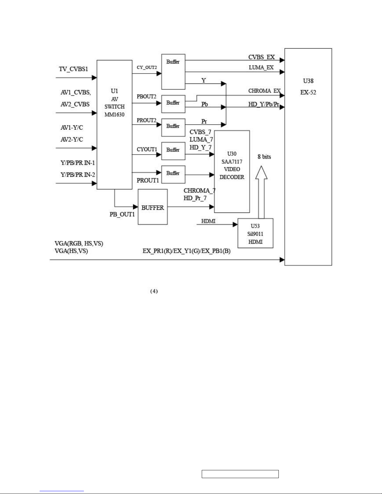
AV (Video) Input circuit (AV,S,YPbPr,PC,HDMI ): (AS block diagram 4)
• AV IN:AV1、AV2 、S1、S2、YPbPr1 、YPbPr2 、HDMI、PC
•AV BOX AV1 or AV2 Input:
• Composite video output signal of external AV1 or AV2 device respectively input IC U1 Video/Audio
SWITCH Input port PIN 65,71 and switch signal with other Video Source in CPU controlled inner switch circuit.
• U1 Composite video output:
After switching with other Video Signal source, output from U1 PIN 60 (signal mark CYOUT 2) goes through Q38 Video
buffer (signal mark CVBS_EX) and input U38 Scaler IC EX-52 input jack (Pin 243) (CVBS2)directly.
Switches with other input signals in U38 inner switch circuit.
• PIP/POP mode
U3 PIN 56 output AV composite image signal (CYOUT1) via Buffer Q36 translate into CVBS_7 signal then
input U30 SA7117 Video decode PIN L3 to proceed PIP/POP function in PIP/POP mode .
• S 、Composite video Terminal.
• U3 S1 or S2 input
S video include Y,C siganl . S1Y1 & C1 input respectively U3 PIN67,69 .S2 Y2 &C2 input respectively
from U3 PIN73,75.Switch signal with other Video Source in U1 inner switch circuit.
• U3 S Output
S(Y/C) output respectively from PIN56 and 55 .Y singal via Buffer(Q29) translates into LUMA_7 than input
U30 SA7117 Video decode PIN k2.
• PIP/POP mode
Via Buffer Q36,C signal (PBOUT2) translate into CHROMA_7 and input U30 SA7117 Video decode PIN
H2 to proceed PIP/POP function in PIP/POP mode .
• HDTV
: Receives outside AV DEVICE Component Video signal .YIN_1,PBIN_1,PRIN_1 input respectively U1
PIN21,23,25 and Switch signal with other Video Source in U1 inner switch circuit than Y via Q37 Video buffer
input U38 EX-52 PORT Y_G1(PIN246),Pb viaQ40 Video buffer input U38 EX-52 PORT PB_B1(PIN232),Pr via
Q39 Video buffer input U38EX-52 PORT PB_R1(pin225) and Switch signal with other Video Source in EX_52 .
• HDMI: Receives outside AV DEVICE HDMI Digital , U53 Sil9011 translate Digital Video signal decode into
24 bits Digital RGB signal DIN[0:23],than input U38 EX-52 Digital PORT DIN[0:23] and switch with other Audio
source in EX-52 .
• PC(VGA) signal includes: R、G、B、HS (Horizontal sync signal)、VS (Vertical sync signal), R transmits to U38
EX-52 PORT PR_R2_G1(PIN226)、G transmits to U38 EX-52 PORT Y_G2(PIN248)、B transmits to U38 EX-52
PORT PB_B2(PIN233) and switch with other EX-52 inner signals. HS(Horizontal sync signal) transmits to U38
EX-52 PORT AIN_HS(PIN10),VS (Vertical sync signal ) transmits to U38 EX-52 PORT AIN_VS(PIN11).
• U38 EX-52 transmits digital Video via LVDS (TXOUT0:3+,TXOUT0:3-) to PIN Set J10 and show out the image.
ViewSonic Corporation Confidential - Do Not Copy
12
N3260w_N3760w_N4060w
N3260wb_N3760wb-1NT
Page 14
ViewSonic Corporation Confidential - Do Not Copy
13
N3260w_N3760w_N4060w
N3260wb_N3760wb-1NT
Page 15
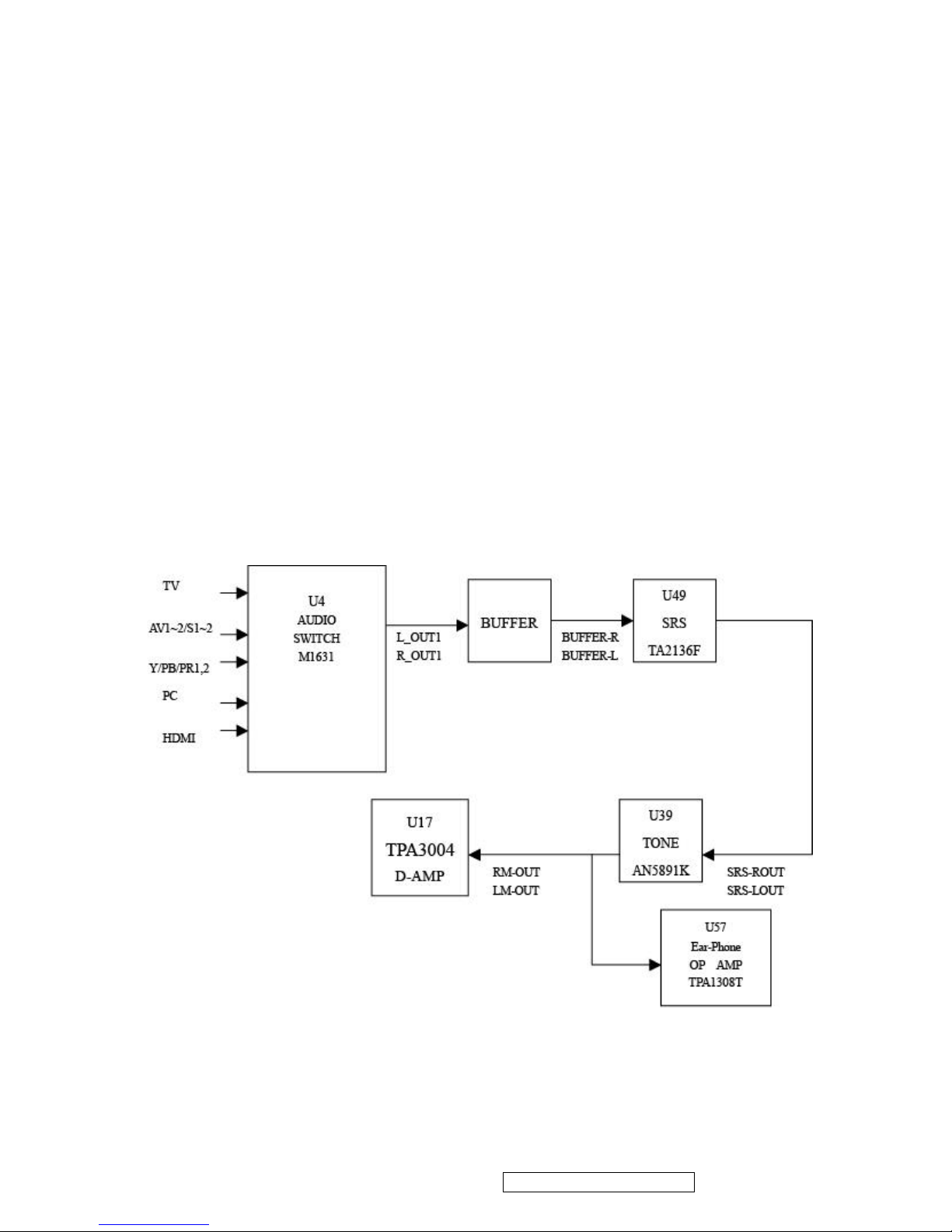
AV Input Circuit(Audio):
• AV Audio input signal includes:AV(1,2)、S(1,2)、HDTV(1,2)、PC、TV、HDMI
• AV 1(S1),AV2(S2) Audio R/L Signals input respectively U4 MM1631 Audio Switch PIN35,36/PIN33,34 to
switch with other audio input source than output from U4 29,30 via Q25,Q26 Audio Buffer and input U49 SRS
TA2136F PIN1,2 to process SRS processing then output from PIN11,12.Input U39AN5891K PIN3,22 for sound
effect working .
• U39AN5891K PIN 12,13 output earphone signal and variable audio voice .Earphone signal trainsmits to U57
TDA1308T AMP to amplify earphone volum .
• HDTV (Y/Pb/Pr) left and right audio signals input repectively U4 MM1631 Audio Switch PIN1,2/3,4
• PC(VGA) left and right audio signals input to U22 MM1631 Audio Switch PIN 7,8 .
• HDMI Audio :
• Digital Audio signal :Via U53 Sil9011 Digital Vedio Decode decoded into I2s digital audio signal and via
U56 CS4334 D/A translate into analog audio signal than input U4 MM1631 Audio Switch PIN9,10.
• Analog Audio signal :input U4 MM1631 Audio Switch PIN 11,12.
• Digital /Analog Audio signal switch by OSD memu.
• After R/L audio signals switching (include AV,S,HDTV ,PC ,TV and HDMI ),All signals output from U39 AN5891
PIN12,13 and trainsmit to U17 TPA3004 amplify and output.
ViewSonic Corporation Confidential - Do Not Copy
14
N3260w_N3760w_N4060w
N3260wb_N3760wb-1NT
Page 16
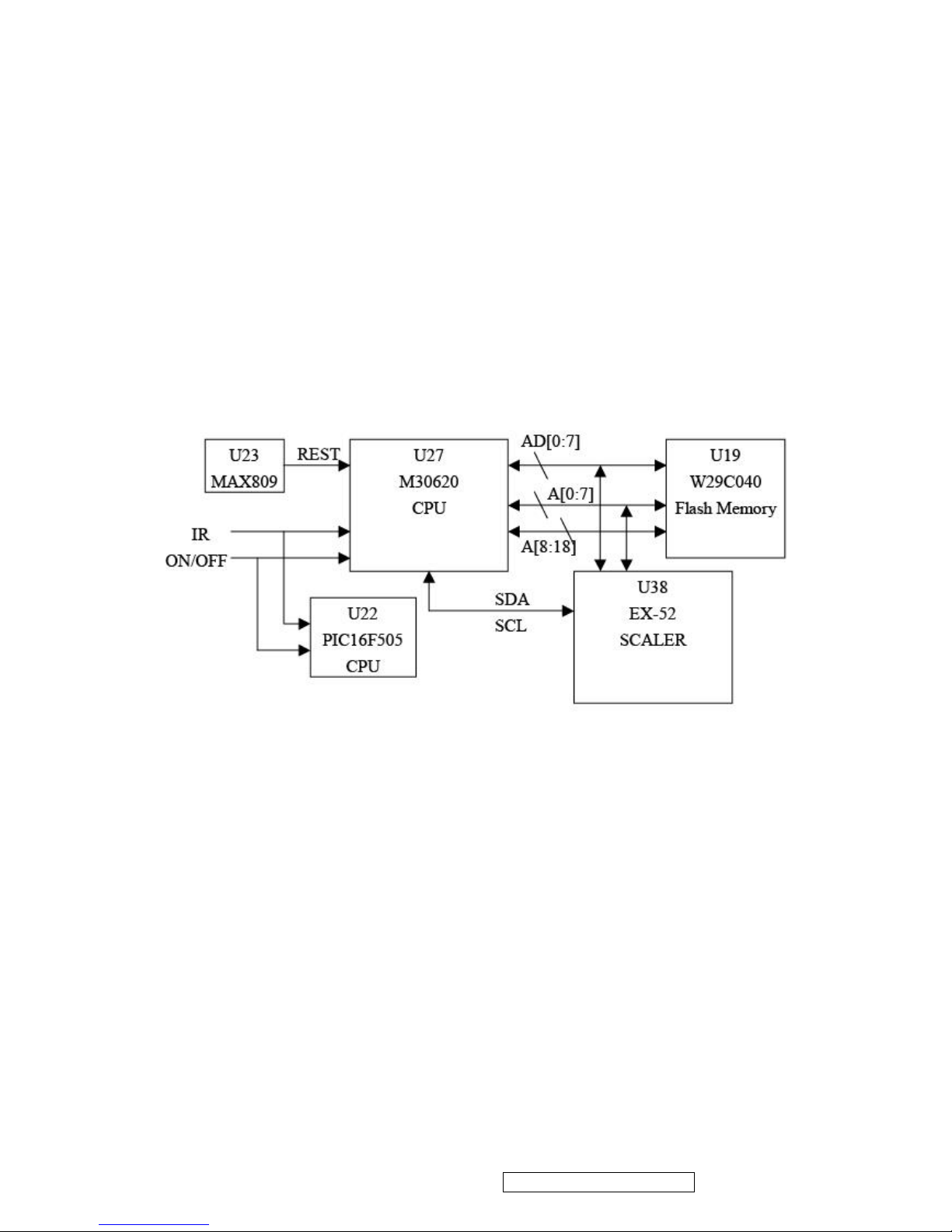
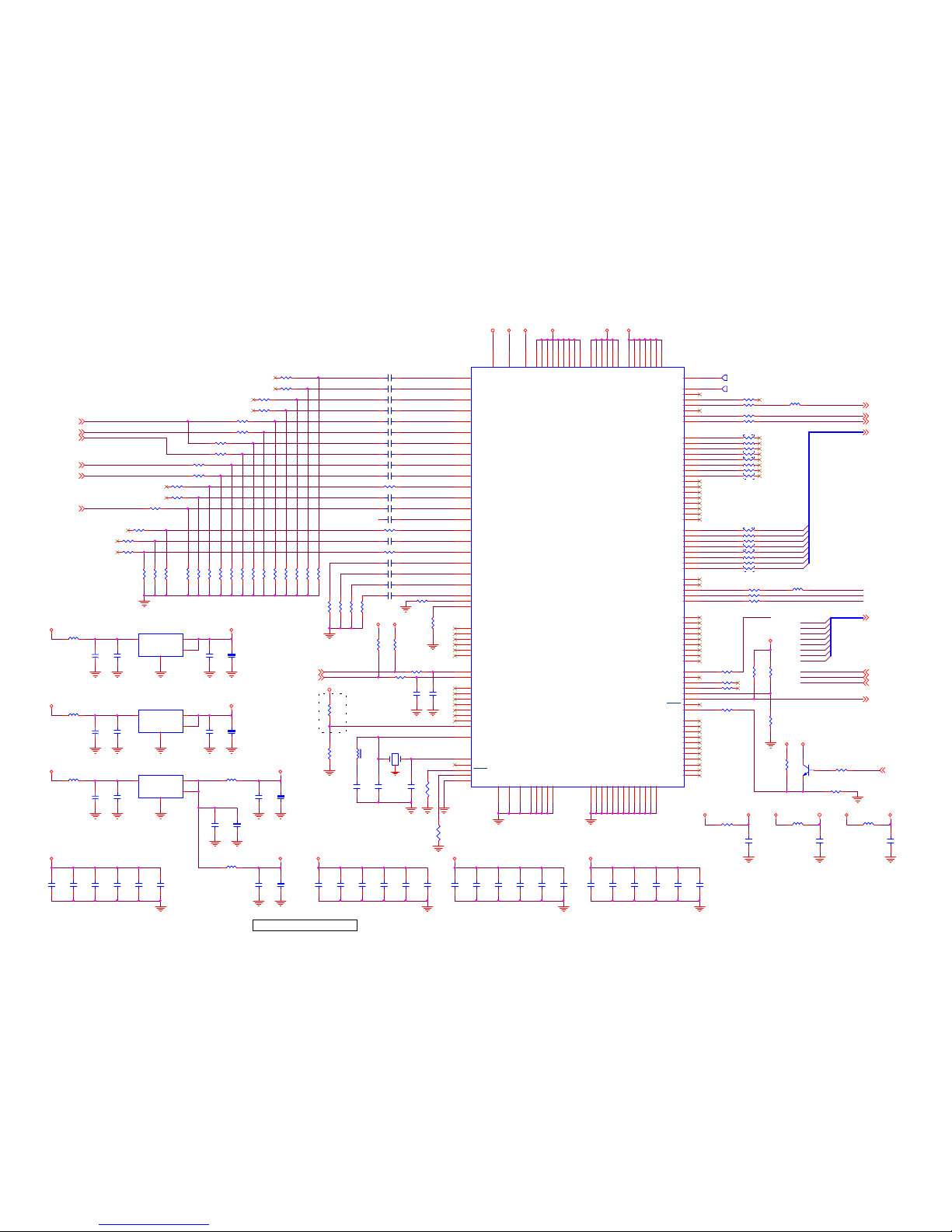
CPU circuit
• U27 M30620 is 16 BITS CMOS CPU,the main CPU of the system.
• (Address Bus):A[0:7] and A[8:18]
• Data Bus) :AD[0:7]
• U19 W29C040 is 4Megabit(512K X 8- bit) Flash Memory,the main function is store program.
• U23 is Reset IC,reset CPU U29 at the beginning of Power ON
• CPU U27 via I2C SDA/SCL(SDA_5V /SCL_5V) to connect and control U38 SCALER IC EX52 and transmits data
via Address Bus:A[0:7] and Data Bus :AD[0:7].
• U22 PIC16F505 is the second CPU,the main function is instead the main CPU U27 M30620 to detect Remote
controller and control On/Off button to order the system power on while this machine is in Stand-By mode. This
step can assure this machine has low consumption power as it is in Stand-By
mode.
ViewSonic Corporation Confidential - Do Not Copy
15
N3260w_N3760w_N4060w
N3260wb_N3760wb-1NT
Page 17
5. Adjusting Procedure (Service mode)
An internal settings service menu is provided to allow adjustment of the device by qualified
service personal. Improper use of the internal settings service menu may render the device
unusable. Refer to the following sections to learn how to operate the service menu.
Equipment Needed
This is necessary to burning LCD TV set about 30 MIN. before start Adjusting Procedure .
Starting the service mode
To start the service mode of operation and view the internal settings menu, do the following:
1. Switch on the LCD TV and make sure that the TV mode is selected.
to enter the internal settings menu.
3. Press ▲ and ▼ to scroll through the various menu options.
4. Press ◄ and ► to change the menu settings.
5. Press EXIT to save the new settings and exit.
6. Press DISPLAY to switch the service mode pages.
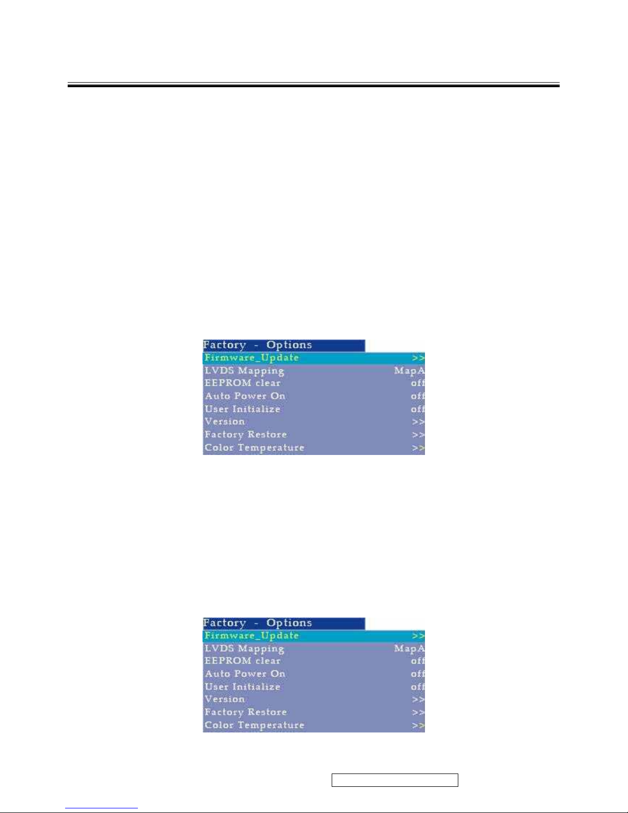
Factory Option
Firmware Update Connect to the equipment and update new software.
EEPROM clear While it displays the word “OK”, it finishes clearing.
Auto Power Up As the order shows “On”, it will turn on the power as you
connect to the power plug.
User Initialize off The suitable mode for customers.
Version Display the software version.
Factory Restore (no support)
Color Temperature Adjusts the image color intensity
ViewSonic Corporation Confidential - Do Not Copy
16
2. Press 100 991 (-/-- button followed by 991 on the number buttons) on the remote control
N3260w_N3760w_N4060w
N3260wb_N3760wb-1NT
Page 18
ViewSonic Corporation Confidential - Do Not Copy
17
N3260w_N3760w_N4060w
N3260wb_N3760wb-1NT
Page 19
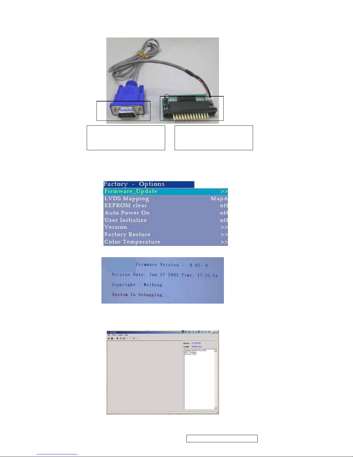
Firmware Upgrade/Upgrade
1.connect Cable
Connect to the LPT1 jack
of PC
Connect to the VGA jack
of TV set
2. After connect the cable, turn on the TV set and enter Adjusting Procedure
Factory mode select [Firmware Upgrade] and press
► key to enter upgrade mode
TL3241T
3. Enter the [IAP Writer] on PC and enter the burner program.
ViewSonic Corporation Confidential - Do Not Copy
18
N3260w_N3760w_N4060w
N3260wb_N3760wb-1NT
Page 20
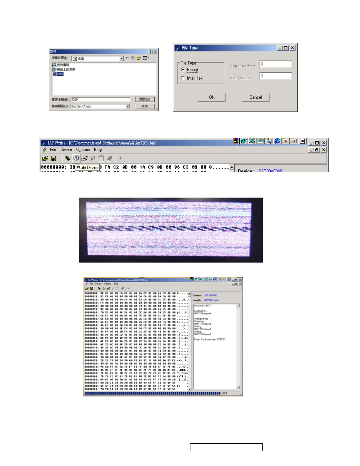
4. Press [open file] icon and show [open file] window picture. Select the file and
Press [OK]
5.Press [Write Device] and start writing.
The screen of TV SET when writing.
The write Device OK.
5. When writing finish, it is necessary to unplug and plug AC power. Turn on the TV
set and the upgrade OK
ViewSonic Corporation Confidential - Do Not Copy
19
N3260w_N3760w_N4060w
N3260wb_N3760wb-1NT
Page 21
Firmware Original Setting
【Factory-Options】:
X: no this function.
Item Original Setting Describe
TV/AV/S HDTV PC/DVI
Fireware Update X
Check Software version and update date when
press ►
LVDS Mapping X No Function
EEPROM clear off Clean EEPROM data
Auto Power Up off Turn on setting automatically
User Initialize X Original setting automatically
Version X Check software version when press ►
Factory Restore X Back to factory setting.
Color temperature
【TCD3】:
Item Original Setting Describe
TV/AV/S HDTV PC/DVI
Bright Middle 036 X Adjusts bright middle setting
Contrast Middle 107 X Adjusts contrast middle setting
Sharpness Middle: 002 X Adjusts sharpness middle setting
Color Middle: 152 X Adjusts color middle setting
Hue Middle: X Adjusts hue middle setting
YC Delay 000 X no function
U Delay 007 007 007 no function
V Delay 005 005 007 no function
PWM 110 110 110 Adjusts background bright .
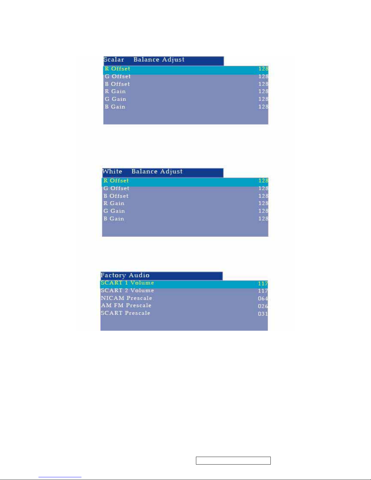
【ScalerWhite Balance Adjust】:
Item Original Setting Describe
TV/AV/S HDTV PC/DVI
R offset 129 129 133 Adjusts R Offset
G offset 130 130 135 Adjusts R Offset
B offset 134 134 130 Adjusts R Offset
R Gain 135 135 157 Adjusts R gain
G gain 130 130 150 Adjusts R gain
B gain 137 137 176 Adjusts R gain
ViewSonic Corporation Confidential - Do Not Copy
20
N3260w_N3760w_N4060w
N3260wb_N3760wb-1NT
Page 22

Function Test
A. Control Bottom (control panel and remote control)
Check item Describe
POWER Press [POWER] to turn ON or OFF LCD TV
Press [SLEEP] to set the off timer from 15 to 120 min.
Remote control
effective range
The effective range is 5 meter from LCD sensor.
Indicator LED TURN ON : green light
TRUN OFF (standby mode): red light
DPMS state for PC/HDMI mode :orange light
EARPHONE Plug in the earphone, check the speakers is mute
Plug in the earphone, check the earphone is working
Plug in the earphone, Adjust the VOLUME and make sure the
volume of earphone follow the adjusting
MENU Press [MENU] key to make sure the OSD picture will show out
CHANNEL
Press [Channel]
▲ ▼ to check the channel number change normally
Press [RECALL] to check switching previously viewed channel normally
Press [NUMBER KEY] and [100] to enter the channel number
VOLUME Press + - to check the volume Increases or decreases
SOURCE Press [SOURCE] KEY and check each signal source is normally
Press [HDMI], [PC], [S-VIDEO], [AV], [COMPONENT] to enter
HDMI,PC,S-VIDEO, AV,COMPONENT mode
SCREEN Press [WIDE] will switches in several screen
mode :AUTO,4:3,16:9,Zoom,14:9)
Press [Display] will show the input signal source
Press [POWER SAVING] to select standard or soft to saving
power.
AUDIO Press [AUDIO MODE] to switch the audio mode: custom , soft ,
standard
Press [MUTE] to disable the audio output
Press [SRS] to switch SRS ON or OFF, STEREO SURROUND,
and MONO SURRONUD.
Press [SOUND AI] to adjust volume automatically.
Press [立體雙語 SOUND] to switch MONAURAL,STEREO mode.
VIDEO Press [VIDEO MODE] to switch video mode: custom, vivid, mild,
and standard.
Press [PIP/POP] to toggles between PIP and POP modes.
ViewSonic Corporation Confidential - Do Not Copy
21
N3260w_N3760w_N4060w
N3260wb_N3760wb-1NT
Page 23

B. OSD (MENU)
Press [menu] to check the OSD and adjust by
▲ ▼◄ ►KEY
Check item Describe
VIDEO
Press
▲ ▼ to check the BAR slide :picture mode- contrast - brightness-
colour- tint- sharpness –NR-
Press
◄ ► to check the red bar or number increases or decreases.
Picture mode : custom ,vivid ,mild ,standard
NR: ON,OFF
AUDIO
Press
▲ ▼ to check the BAR slide : volume- treble -bass-balancer-
SRS- MTS –audio mode-HDMI Audio
Press
◄ ► to check the red bar or number increases or decreases.
SRS : SRS ON, SRS OFF, stereo surround, mono surround.
MTS: ON,OFF
Audio Mode: custom, soft, standard
HDMI Audio: digital, analog
SCREEN
Press
▲ ▼ to check the BAR slide : display mode – default- color
temperature (PC ONLY:phase, clock,H position, V position, auto Sync)
Press
◄ ► to check the red bar or number increases or decreases.
Display mode: Auto,4:3,16:9,Zoom,14:9.
Color temperature: cold,standard,warm
SETUP
Press
▲ ▼ to check the BAR slide : tuning-auto search
Tuning
Press ▲ ▼ to check the BAR slide : CH-type-CH NO.- favorite CH -skip-
fine tuning-manual search
Press ◄ ► to check the red bar or number increases or decreases.
CH type : cable, TV.
Favorites CH: 12 Channels setting
SKIP: Select ON to delete the channel from channel list. Press [EXIT] to
make sure the channel has been deleted.
Fine tuning: press ◄ ►to adjust the frequency of channel. Check the
vision behavior Press [EXIT] to make sure the setting has been saved.
OPTION
Press
▲ ▼ to check the BAR slide : menu language-sleep timer-menu
background-source information-reset-PC display
Press ◄ ► to check the item correctly.
Menu language: Check the display language correctly (Chinese, English).
Sleep timer: From OFF –15-…-120MIN.
MENU background: Adjust the background color from light to heavy
Opaque/mode1/mode2/mode3/mode4
Reset: Reset all OSD setting to original setting.
PC display: adjusts the resolution of TV set in PC MODE
ViewSonic Corporation Confidential - Do Not Copy
22
N3260w_N3760w_N4060w
N3260wb_N3760wb-1NT
Page 24

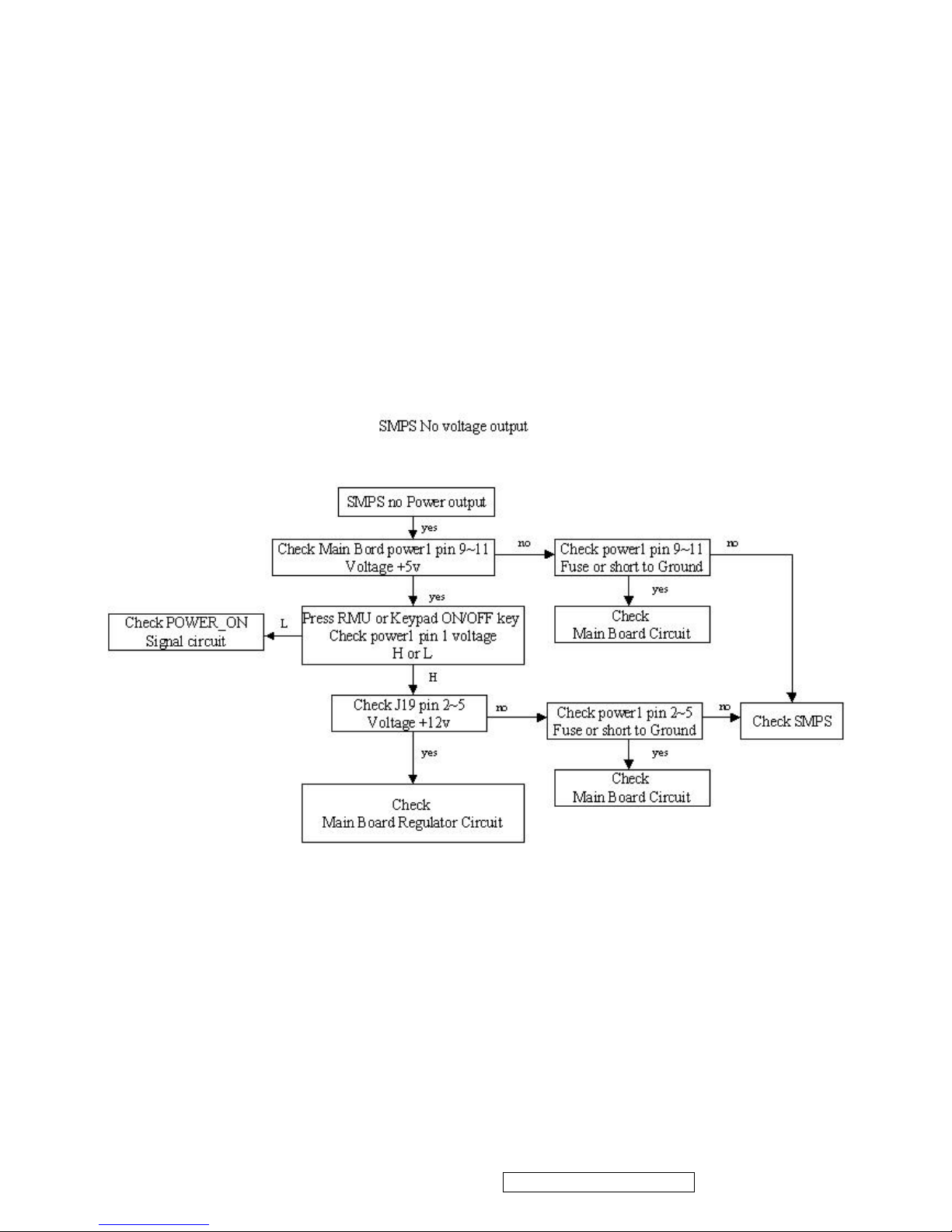
6. Trouble Shooting Flow Chart
No power
z Make sure the LCD is properly connected. (see also pages 12)
z Make sure the AC power cord is properly connected. (see also page 12)
z Make sure the AC power is ON, DC power button is ON (Green LED).
z
Plug another electrical device (like a radio) to the power outlet to verify that the outlet is
supplying the proper voltage.
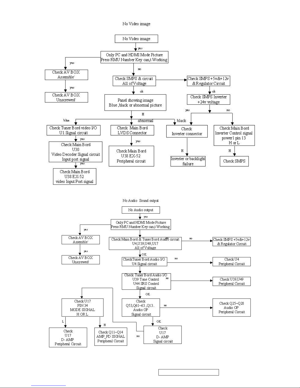
Poor or no picture
z The TV station may be experiencing problems. Try another channel.
z The Cable TV signal may be scrambled or encoded. Please contact your local cable
operator.
z Make sure that connection to other components are correct. (see also pages 12)
z Make sure that setup has been done correctly after connections. (see also pages 14-19)
z Make sure the correct input is selected and the input signal is compatible.
Strange color, light color, or color misalignment
z Ensure that the video cable is securely connected.
z The picture may appear dim in a brightly lit room.
z Adjust brightness and contrast.
z Check the input signal setting.
No sound
z Check your audio connections
z The MUTE button may have been pressed, try pressing this button again.
z Check your audio settings, your TV audio may be set to minimum.
z Press the Volume + (Up) button on the remote control.
Remote control unit does not operate
z Make sure batteries are inserted correctly. (see also page 11)
z Batteries could be weak or dead. Replace batteries.
z Is a fluorescent light illuminated near the remote control sensor?
z The path of the remote control beam may be blocked. Make sure the path is clear and that
the remote control is aimed at the remote control sensor on the TV.
z Press only one button at a time and it is the correct one for the operation you want to
perform.
Unit cannot be operated
z External influences such as lightning or static electricity may cause improper operation. In
this case, operate the unit after first turning on the power of the LCD and the AVC System,
or unplug the AC cord for 1 to 2 minutes, then replug again.
Power is cut off suddenly
z Is the sleep timer set? (see also page 19)
ViewSonic Corporation Confidential - Do Not Copy
23
N3260w_N3760w_N4060w
N3260wb_N3760wb-1NT
Page 25
z The internal temperature of the unit has increased. Remove any objects blocking the vent
or clean as necessary.
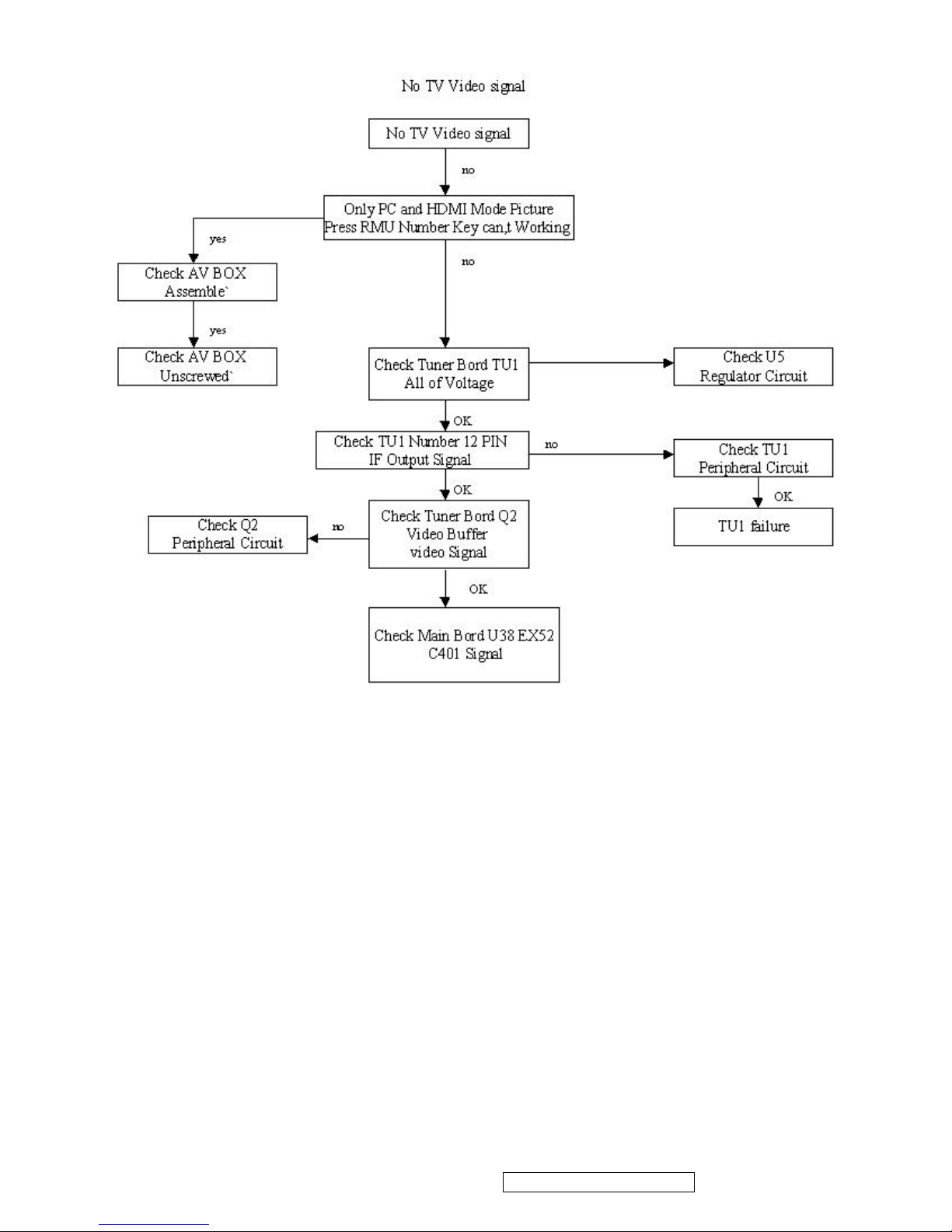
No CATV reception (or no reception above CH13)
z Is the AIR/CABLE option set correctly? Please set the AIR/CABLE option to CABLE.
z CATV is connected improperly or not connected; please check all the CATV connections.
z The cable TV service is interrupted; please contact your cable operator.
Picture is cut off/with sidebar screen
z Is the image positioned correctly?
z Are screen mode adjustments such as picture size set correctly?
ViewSonic Corporation Confidential - Do Not Copy
24
N3260w_N3760w_N4060w
N3260wb_N3760wb-1NT
Page 26
ViewSonic Corporation Confidential - Do Not Copy
25
N3260w_N3760w_N4060w
N3260wb_N3760wb-1NT
Page 27
ViewSonic Corporation Confidential - Do Not Copy
26
N3260w_N3760w_N4060w
N3260wb_N3760wb-1NT
Page 28
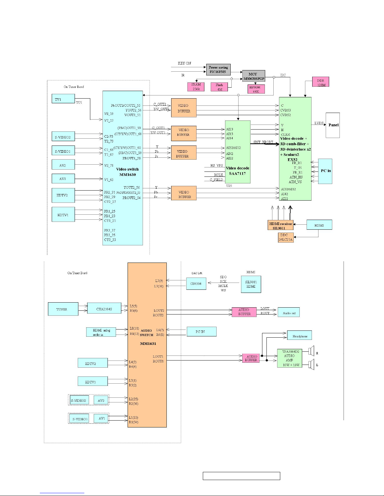
7. Block Diagram
32 ”/37”/40”
ViewSonic Corporation Confidential - Do Not Copy
27
N3260w_N3760w_N4060w
N3260wb_N3760wb-1NT
Page 29
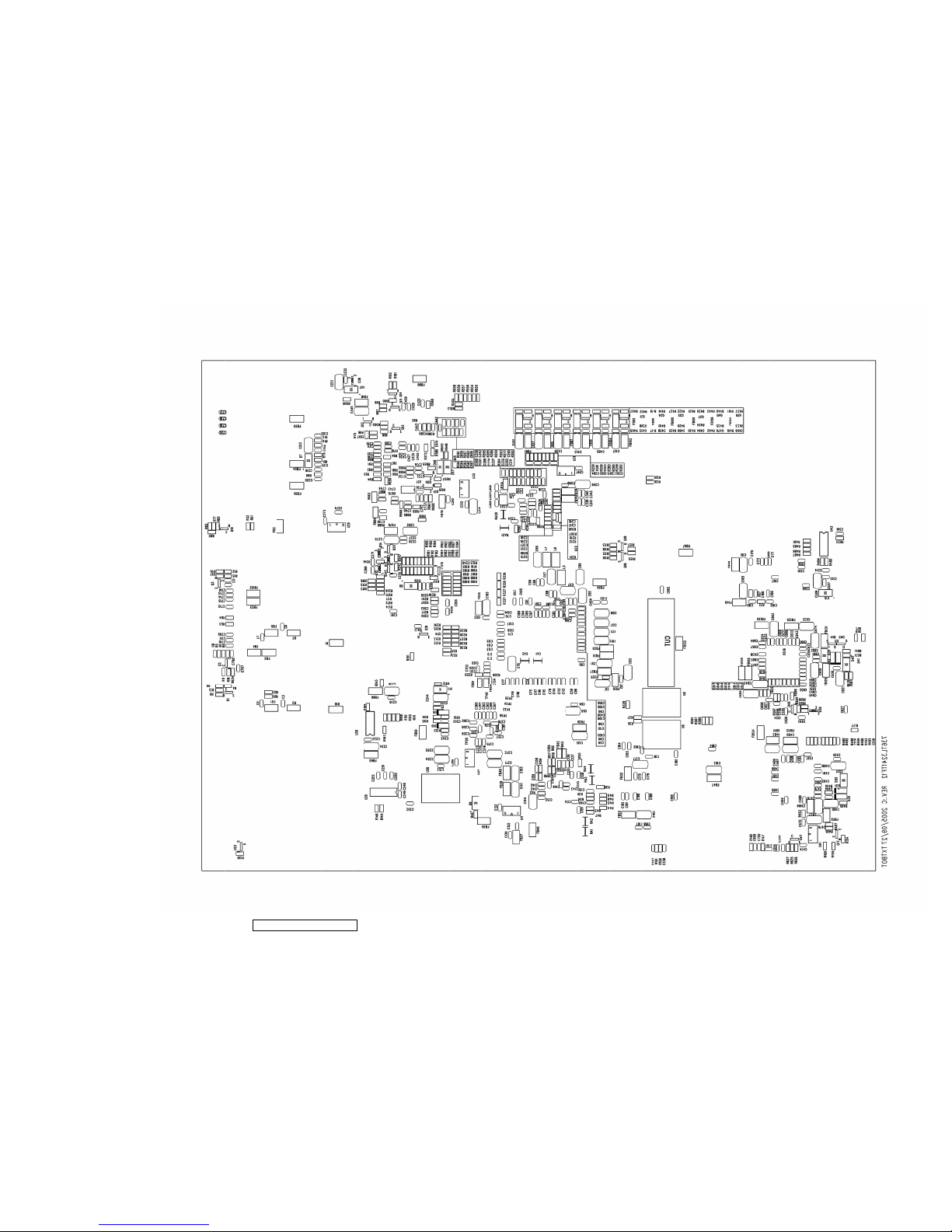
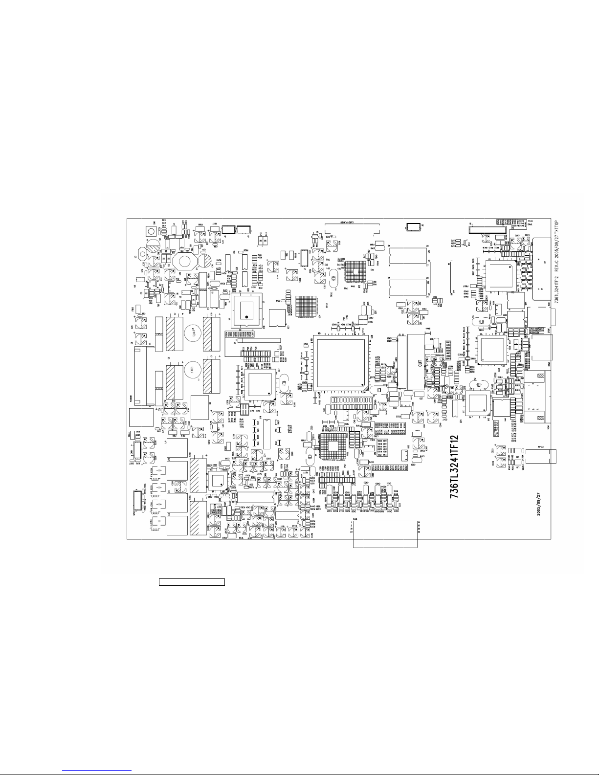
8. PCB Layout Diagrams
ViewSonic Corporation Confidential - Do Not Copy
28
N3260w_N3760w_N4060w
N3260wb_N3760wb-1NT
Page 30
ViewSonic Corporation Confidential - Do Not Copy
29
N3260w_N3760w_N4060w
N3260wb_N3760wb-1NT
Page 31

ViewSonic Corporation Confidential - Do Not Copy
30
N3260w_N3760w_N4060w
N3260wb_N3760wb-1NT
Page 32

ViewSonic Corporation Confidential - Do Not Copy
31
N3260w_N3760w_N4060w
N3260wb_N3760wb-1NT
Page 33

SB_PWR
5V_SB
INV_ON
EXT_PWM
BKLT_CNTL
5V
5V
3.3V
5V
5V
5V_SB
GND
VCC
GND GND
GND
GND
GND GND GND
GND
GND
GND
GNDGNDGND
GND
GND
5V_SB
VCC_12V
PVDD
GND GND GND
GND
5V_SB5V_SB
GND
5V
GNDGND GND
3V3_SB
GND
GND
GNDGND
9VA
GND
5V_SB
GND-AMP
5V_SB
VCC_ AMP
GND
VCC_12V
GND
VCC
GND
5V_SB
GND
5V_P5V
GND GND
VCC_12V
VCC_12V
GND GND
9VB
GND
GNDGND
GND GNDGND
GND
N16810698
VCC
GNDGND GND
VCC
GND
VCC
GND
GND
GND GND
GND GND
GND GND
GND GND
GND GND
GND GND
GND GND
GND GND
POWER_ON7
SB_PWR6
POW ER_ON7
BKLT_PWR7
EXT_PWM 10
BKLT_CNTL 7
close to pin 2
close to pin 1
15mils
close to pin 1
15mils
15mils
400mils
400mils
10mils
SO-8
H : Power Off
L : Power On
H : System Off
L : System On
NT3760w-NT NT4060w-NT use FB10
NT3260w-NT use FB11
NT3760w-NT NT4060w-NT use FB10
NT3260w-NT use FB11
R23
1K 1%
P Channel
U2
SI4435
S
1
S
2
S
3
G4D
5
D
6
D
7
D
8
R8
0_NS
+
C12
100uF
L4
SSL0804T-4R7M-S
1 2
R14
10K
U1
APL1117_3.3
GND
1
VO
2
VI
3
TAB
4
Q5
IRF7821
1 32
4
5 6 7 8
Q4
IRF7821
1
3
2
4
5
6
7
8
C38
100nF
Q8
MMBT3904
1
2 3
C715100nF
R13
100_NS
FB10
PBY32_19 0HM_NS
C711100nF
+
C41
47uF
C7
100nF
R2
1K
C21
100nF
D5
1N4148
12
R10
1K
D3 1N4148
1 2
R20
0
RG7 0
U3
IRU3037ACS
Fb
1
VCC
2
LDrv
3
GND
4
SS
8
Comp
7
Vc
6
HDrv
5
FB17
PBY 32_120 OHM
RG1 0
R21
10k
+
C10
1000uF
F3
6.3A/250V
C14
100nF
C6
100nF
+
C43
100uF
+
C44
100uF
Q6
MMBT3904
1
2 3
L3
SSL0402T-1R0M-S
1 2
+
C15
100uF
C716100nF
C709100nF
C712100nF
FB122
PBY32_19 OHM
+
C19 680uF
R15 0
RG8 0
R17 4.7K
FB15
PBY 32_120 OHM
+
C47
100uF
C39
100nF
FB8
PBY32_19 OHM
C32
100nF
C16
100nF
C13
100nF
FB18
PBY32_120 OHM
R4
4.7K
+
C35
100uF
FB1
PBY32_19 OHM
FB5
PBY32_19 OHM
FB2
PBY32_19 OHM
FB11
PBY 32_19 OHM
+
C25
47uF
L2
10uH/COIL
1 2
R12 1K
POWER1
CONN RECT 13
1
2
3
4
5
6
7
8
9
10
11
12
13
C710100nF
R33 4.7K
C26
100nF
C46
100nF
C28
100nF
R22 3.16K 1%
C11
100nF
R19
0
FB3
PBY32_19 OHM
R18
4.7
C8
10nF
C42
100nF
C24 NS
+
C18
150uF
Q7
MMBT3904
1
2 3
C34
100nF
R11
1K
+
C5
470uF
+
C1
1000uF
R3
560
C714100nF
R624
10K
C33
100nF
+
C9
100uF
C3
100nF
+
C40
100uF
D2 1N4148
1 2
U6
LM7809_T0263_3
GND
2
VO
3
VI
1
R16 330
C20
100nF
R32
1K
+
C37
100uF
R7
1K
L1
10uH/COIL
1 2
R6 0
C31
10nF
R9 10K
R1
10K_NS
R5 22
+
C36
100uF
RG3 0
Q1
MMBT3904
1
2 3
Q3
MMBT3904
1
2 3
R27 10k
C713100nF
C30
100nF
+
C2
470uF
C708100nF
C27
1uF
FB19
PBY32_120 OHM
D1 1N4148
1 2
U4
LM7809_T0263_3
GND
2
VO
3
VI
1
FB7
PBY 32_120 OHM
F1 FUSE
RG4 0
F2
FUSE
D4
1N4148
12
RG5 0
C23
470pF
R29
10k
RG2 0
Q2
MMBT3904
1
2 3
FB4
PBY32_19 OHM
+
C29
100uF
R31
0
FB121
PBY32_19 OHM_NS
C707100nF
C4
100nF
P Channel
U5
SI4435
S
1
S
2
S
3
G4D
5
D
6
D
7
D
8
R26 1K
R25 47K
+
C22
100uF
R24
0
+
C17
220uF
RG6 0
C45
100nF
9. Schematic Diagrams
9.1 POWER
ViewSonic Corporation Confidential - Do Not Copy
32
N3260w_N3760w_N4060w
N3260wb_N3760wb-1NT
Page 34

PAVDD1PAVDD2
AVSS3_BG_ASS
AVSS_ADC2
AVSS_ADC1
VSSH VSSH
EX-VSSC
VSSL
PDVDD
PDVSS
PAVDD
PAVSS
AVSS_ADC3
GNDGND
GND
GND GND
5V EX-VD3_3
GND GND
EX-VL1_8 PAVDD1PAVDD2
AVDD1
AVDD2
GND
GND
GND
EX-VDDL
EX-VA1_8
EX-VDDL
EX-VD3_3
3V3_SB
GND
EX-VD1_9
GND GND GND GND GND
3.3V EX-VL1_8
VDDH
AVDDSP
GNDGND
GND
GND GND
3.3V EX-VD1_9
EX-VD3_3
EX-VD3_3
EX-VD3_3
EX-VDDL
VDDMQ
3.3V EX-VA1_8
GND
VDH
3V3_SB
EX-VA1_8
EX-VL1_8
GND
EX-VD1_9
VDDL
GND GND
EX-VL1_8 EX-VL1_8
PDVDD PAVDD
AVDD3EX-VA1_8
GND
GND
LVDSVCC
GND
LVDSPLL
GND
LVDSVDD
GND GND GND GND GND
GND
GND GND
GND
0.24A
1.12A
0.06A
1.8V Power
for SVP-EX
ANALOG
1.9V Power
for SVP-EX
DIGITAL
1.8V Power
for SVP-EX
CORE
SVP-EX
3.3V
Power
LVDS 386: 0.48A
EX-52: 0.25A
C110
100nF
C82
100nF
FB34
PBY32_120 OHM
22uF
C51
C90
100nF
C122
100nF
C53
100nF
C85
100nF
C70
100nF
C108
100nF
22uF
C97
22uF
C111
C124
100nF
C86
100nF
C58
100nF
FB27
PBY 32_120 OHM
22uF
C91
22uF
C83
U8
APL1084_ADJ
GND
1
VO
2
VI
3
C66
100nF
C116
100nF
U10
APL1117_1.8
VI
3
GND
1
VO
2
TAB
4
FB21
PBY32_120 OHM
FB33
PBY32_120 OHM
+
C52
100uF
FB25
PBY32_120 OHM
C63
100nF
L5 10uH
L7 10uH
U9
APL1084_3.3
GND
1
VO
2
VI
3
FB35
PBY 32_120 OHM
C72
100nF
22uF
C93
C88
100nF
C56
100nF
C125
100nF
C62
100nF
C121
100nF
C71
100nF
C94
100nF
C123
100nF
C60
100nF
FB29
PBY32_120 OHM
FB23
PBY32_120 OHM
C50
100nF
C119
100nF
C105
100nF
C75
100nF
C120
100nF
22uF
C67
22uF
C95
C113
100nF
22uF
C87
C117
100nF
FB20
PBY32_120 OHM
22uF
C109
C112
100nF
FB30
PBY32_120 OHM
C98
100nF
C106
100nF
R36 210
22uF
C57
C96
100nF
C115
100nF
C127
100nF
22uF
C107
C61
100nF
22uF
C101
FB31
PBY 32_120 OHM
22uF
C103
22uF
C89
FB32
PBY 32_120 OHM
C68
100nF
C81
100nF
22uF
C79
C99
100nF
C59
100nF
22uF
C69
C114
100nF
C73
100nF
22uF
C78
+
C48
100uF
C76
100nF
U7
APL1117_1.8
VI
3
GND
1
VO
2
TAB
4
+
C84
100uF
L6 10uH
C102
100nF
22uF
C65
C92
100nF
C54
100nF
C126
100nF
C74
100nF
R37
110
+
C80
100uF
C49
100nF
22uF
C55
FB28
PBY32_120 OHM
FB22
PBY 32_120 OHM
C77
100nF
C118
100nF
FB24
PBY32_120 OHM
C100
100nF
C104
100nF
C64
100nF
FB26
PBY32_120 OHM
9.2 EX52 REGULATOR & DECOUPLE CAP
ViewSonic Corporation Confidential - Do Not Copy
33
N3260w_N3760w_N4060w
N3260wb_N3760wb-1NT
Page 35

R_OUT+ L_OUT+
LOUT-
R_OUT+
R_OUT-
R_OUT- L_OUT-
L_OUT+
LOUT+
ROUT+
ROUT-
L_OUT-
PVCCL
PVCCR
AVCP
GND-AMP
GND-AMP
VCC_AMP
VCC_AMP
VCC_AMP
GND-AMP
GND-AMP
PVCCR PVCCR
PVCCL
GND-AMP
PVCCL
GND-AMP
GND
GND
AVCP
GND
5V-1_CPU
5V-1_CPU
MPOWER
5V_SB
5V_SB
AVCP
GND
5V_SB
GND
MPOWER
GNDGND
GND
MPOWER
GND
GND-AMPGND-AMP
GND-AMP
GND-AMP
GND-AMP
GND
GND-AMP
GND-AMP
GND-AMP
GND-AMP
SD
RM_OUT11
LM_OUT11
SD
R_OUT+R_OUT-
L_OUT+L_OUT-
MODE
SD
AMP_PD7
MODE
EAR_LIN
EAR_RIN
R_OUT+
R_OUT-
L_OUT-
L_OUT+
LM_OUT11
RM_OUT11
EAR_LIN
EAR_RIN
6 ohm speaker
(TPA3005D2)
H : AMP O n
L : AMP Off
PITCH 2.0
!
+
C209
10uF
R505
10K_NC
R75 0
C200
220nF
R101
120K
D7
1N4148
12
R85
47K
R73 0_NS
R100
10K
C221
220nF
FB54
PBY 32_120 OHM
C717
100nF
R82
10K
L12
15uH
R80 0
C224
0.47uF
R98
1K
R74 0
C232
100nF
SPK1
2.5 m/m X 4
1
2
3
4
C216 470nF
R92 30K
R87 15K
+
C201
1000uF
C718
100nF
+
C218
220uF
C698
100nF
R96
10K
R95 10K
R88 15K
+
C230
47uF
C219 220pF
L14
COIL-BEAD
C199
220nF
R76 0
C196
100nF
C226
1nF
R79 0_NS
C225
0.47uF
L11
15uH
C223
1nF
22uF
C204
C212 470nF
Q14
MMBT3906
1
32
L8
15uH
FB62
PBY32_120 OHM
L10
COIL-BEAD
R659
0
C719
100nF
R81 0_NS
+
C195
1000uF
C194
0.47uF
R86 0
R89 120K
U17
TPA3004D2
#SHUTDOWN
1
AGND
26
AGND
30
AVCC
33
AVDD
29
AVDDREF
7
BSLN
13
BSLP
24
BSRN
48
BSRP
37
COSC
28
VARDIFF(GAIN0)
9
VARMAX(GAIN1)
10
LINN
6
LINP
5
LOUTN16LOUTN17LOUTP20LOUTP
21
VREF(NC)
8
VAROUTL(NC)
31
VAROUTR(NC)
32
VOLUME(NC)
11
REFGND(NC)
12
MODE(NC)
34
MODE_OUT(NC)
35
PGNDL18PGNDL
19
PGNDR
42
PGNDR
43
PVCCL14PVCCL
15
PVCCL22PVCCL
23
PVCCR38PVCCR
39
PVCCR46PVCCR
47
RINP
3
RINN
2
ROSC
27
ROUTN
44
ROUTN
45
ROUTP
40
ROUTP
41
VCLAMPL
25
VCLAMPR
36
V2P5
4
Q13
MMBT3904
1
2 3
Q10
MMBT3904
1
2 3
+
C207
10uF
R93 30K
L9
15uH
+
C206 10uF
FB64
PBY32_120 OHM
+
C231
22uF
D36
BAT54C
1
2
3
R83
22K
C228
1nF
C720
100nF
C208 470nF
R661
0
Q11
MMBT3906
1
3 2
+
C215
10uF
L15
COIL-BEAD
FB55
PBY 32_120 OHM
C220 1uF
C229
1nF
R102
3.3K
R507
10K
FB63
PBY32_120 OHM
R78 0
R506 1K
R77 0
+
C227
220uF
C203
100nF
EAR1
EARPHONE
1
2
3
4
C222
220nF
22uF
C198
10uF
C213
C197
100nF
R97 1K
R94 0
C202
100nF
C193
0.47uF
R90 15K
C211 470nF
C217 1uF
FB56
PBY 32_120 OHM
L13
COIL-BEAD
D37
ZD5.6B
C205 1uF
Q12
MMBT3904
1
2 3
R91 30K
R99
1K
C697
100nF
R84 0
C214
100nF
C210 470nF
9.3 AUDIO AMP
ViewSonic Corporation Confidential - Do Not Copy
34
N3260w_N3760w_N4060w
N3260wb_N3760wb-1NT
Page 36

WR_EM A18
RST#
RST#_
RD
A6
A3
A2
A1
A[0:7]
A0
A7
A5
A4
AD0
AD5
S_A3
A8
A9
A10
S_A9
S_A10
S_A6
S_A7
S_A1
S_A2
S_A4
S_A8
S_A5
S_AD3
S_AD7
S_AD6
S_AD2
S_A0
S_AD1
S_AD0
S_AD5
S_AD4
S_WR~
RD S_OE~
WR_EM
CS1
KEY_ON
REMOTE_PIC
SCL_5V
SDA_5V
PC_SDA
SCL_5V
SDA_5V
PC_SCL
A18
A0
A1
A2
A3
A4
A7
AD1
AD2
AD3
AD4
AD6
AD7
A5
A6
SCL1
SDA1
KEYA
IR
KEYB
IR
REMOTE
REMOTE_PIC
PS
AD3
AD5
AD0
AD6
AD4
AD7
AD1
AD[0:7]
AD2
MCU_RST
KEY_ON
A11
A17
A11
S_A12
A[8:18]
A16
S_A13
A18
A8
A13
A14
A13
S_A14
A10
A15
A9
A14 A12
A12
S_A11
MCU_RST 7
5V-1_CPU
5V-1_CPU
GNDGND
3V3_SB
GND
GNDGND
5V_SB
GND GND
GND
3.3VC
5V-1_CPU
5V-1_CPU
GND
GND
GND
GND
GND
5V_SB
GND
GND
3.3VC
3.3VC
5V_SB
5V-1_CPU 5V-1_CPU
GND
GND
5V_SB
5V_SB
GND
5V_SB
9VA
GND
GND
9VA4052
GND
5V_SB
5V-1_CPU
5V
GND
GND
GND GND
CS17
RST#_7
RST# 3,13,15
SDA_5V7,11,16
SCL_5V7,11,16
SDA1 3,8,10,15
SCL1 3,8 ,10,15
LED_SB7
LED_G7
KEYA7
KEYB7
KEY_ON
IR
VGA_ID 7
SB_PWR 1
LED_SB 7
MCU _CONTR 7
PS 7
A[8:18]7
A[0:7]7,10
WR_EM7
Detect_VGA7
AD[0:7] 7,10
REMOTE7
SCLE 7
SDAE 7
E_PAGE 7
RD 7
KEY_ON17
XXI7
CE_REMOTE 14
HDMI_ID 7
CE_REMOTE14
XXO 7
EE_CHECK 7
KEY_ON
W27E040
W27E040 USED
W27E040 USED
RESET SAA7117A/SiI169/SiI9011....
PC I2C Debug
When use W27E040,use R420 and
R421;R422 and R423 are Option.
When use W29C040,use R422 and
R423;R420 and R421are Option.
(LM809)
MAX809LD_NS
(SOT-23)
RESET MCU
"#
#
22uF
C236
D11 RD5.1B
C255
100nF
R148
15k
R160 100_NS
D9 SD05
1 2
FB66
PBY 32_120 OHM
C257
15pF
R161
22_NC
U23
OUT
2
GND
1
VCC
3
R126 47
RA8 47R
4
8
7
6
5
2
3
1
Q16
2N7002/SOT_1
312
R125 47
R136 0_NS
SW1
HDK632A
1
3
2
4
R129 47
RA9 47R
1
5
6
7
8
3
2
4
R128 22
C238
10nF
U25C 74HC126
98
14
10
7
C245 100nF
D10 SD05
1 2
C235
100nF
R118
10K
R625
820_NC
R119 100
R140 0_NS
U25A 74HC126
23
14
1
7
R130 47
R105 0_NS
C258
15pF
R628
0_NC
D43
1N4148
1 2
R157 22
J6
HEADER 3_NC
1
2
3
U25B 74HC126
56
14
4
7
R569 100
R106 0
Q182N7002/SOT_1
312
C701 100nF_NC
C243
100pF
R626
330
U21
24LC64
A0
1
A1
2
A2
3
GND4SDA
5
SCL
6
PAGE
7
VCC
8
C253
15pF
R131 47
R134 47_NC
U22 PIC16F505
VDD
1
RB5
2
RB4
3
RB3
4
RC5
5
RC4
6
RC37RC2
8
RC1
9
RC0
10
RB2
11
RB1
12
RB0
13
VSS
14
C237
100nF
R152
4.7K
C242
100pF
R107 0
+
C241
10uF_NS
R133 47
RA7 47R
1
5
6
7
8
3
2
4
R132 47
J4
CONN SOCKET 10
1
2
3
4
5
6
7
8
9
10
R112 47
R108 47_NS
R111 47
R113 10K
R122
100
R156 22
U18
CY7C199C-12VC
D0
11
D1
12
D2
13
D3
15
D4
16
D5
17
D6
18
D7
19
A14
10
A13
9
A12
8
A11
7
A10
6
A9
5
A8
4
A7
3
A3
25
A2
24
A0
21
A1
23
A6
2
A4
26
A5
1
/CE
20
/OE
22
/WE
27
VCC
28
GND
14
+
C256
10uF
R150
4.7K
RA5 47R
1
5
6
7
8
3
2
4
R120
10K_NS
R504
0
U19
W29C040
A0
12
A1
11
A2
10
A3
9
A4
8
A5
7
A8
27
A11
25
A12
4
A7
5
A14
29
A15
3
A6
6
A9
26
A13
28
A10
23
A16
2
A17
30
A18
31
GND
16
VPP
1
VCC
32
OE#
24
CE#
22
Q7
21
Q5
19
Q0
13
Q1
14
Q2
15
Q3
17
Q4
18
Q6
20
RA10 47R
1
5
6
7
8
3
2
4
R158 22
+
C246
100uF
C700 100nF_NC
22uFC244
R153
4.7K
FB67
PBY 32_120 OHM
J5
HEADER 3_NC
1
2
3
R121
4.7K
C247
100nF
R115 10K
R159 22_NC
R147
15k
+
C254
10uF
R110 47
R155 22
RA6 47R
4
8
7
6
5
2
3
1
R114 10K
R137
22K
R135 47
R127 47
R124 47
C699 100nF_NC
9.4 MISC
ViewSonic Corporation Confidential - Do Not Copy
35
N3260w_N3760w_N4060w
N3260wb_N3760wb-1NT
Page 37

CTS1/RTS1
P6_5/CLK1
RXD
TXD
RST_H
PS
RST#_
HOLD
MCU_ALE
MCU_WR
CS
MCU_RDRD
PD_DVIN
LED_G
E_PAGE
V_ST
RGB_ST
VGA_ID
BKLT_CNTL
DVBT_RST#
KEYB
A17
A16
A14
A13
A12
A15
A18
A11
A10
A9
A8
A[8:18]
A6
A5
A7
A3
A2
A4
A1
A0
DVBT_RDY#
S_DET
AMP_PD
MCU_RST
CNVss
INT_A
EX_INT#
SW7
SW8
REMOTE
SW9
SW10
SCLE
BKLT_PWR
CPU1
MUTE
A[0:7]
A0
A1
CTS1/RTS1
P6_5/CLK1
A2
RXD
A3
TXD
MCU_RST
A4
WR_EM
A5A6A7
HOLD
CNVss
HOLD
P5_ 2/RD
P5_ 2/RD
RD
WR_EM
WR_EM
CS1
SCL_5V
ISP_CTRL
SDA_ISP
SCL_5V
ISP_CTRL
KEYA
POWER_ON
KEY_ON1
SDA_5V
SDA_5V
SCL _ISP
7117_CE
88610_RST
AD5
AD[0:7]
AD1
AD6
AD2
AD3
AD7
AD4
AD0
SDAE
MCU _CONTR
GND GND
GND
5V-1_CPU
GND GND
5V-1_CPU
GND
5V-1_CPU
GNDGND
GND
5V-1_CPU
GND
5V-1_CPU
5VR9VA
5V-1_CPU
GND GND
5V-1_CPU
GND GNDGND
GND
GND
GND
5V-1_CPU
5V-1_CPU
5V-1_CPU
GND
5V-1_CPU
5VR
5V-1_CPU
GND
5V-1_CPU
5V-1_CPU5V-1_CPU
GND
5V-1_CPU
GND
GND
5V-1_CPU
GNDGNDGND
5V-1_CPU
5V_SB
5V-1_CPU5V-1_CPU
GND
VGA_ID6
DVBT_RDY#16
KEYB6
KEYA6
AMP_PD5
DVBT_RST#16
BKLT_CNTL1
POW ER_ON1
LED_G6
E_PAGE6
PD_DVIN13
BKLT_PWR1
SCLE6
MUTE16
KEY_ON16
7117_CE8
88610_RST3
EX_INT#10
REMOTE6
INT_A8
MCU_RST6
SCL _ISP14
SDA_ISP14
A[0:7] 6,10
A[8:18] 6
AD[0:7] 6,10
MCU_RD 10
MCU_WR 10
CS 10
WR_EM 6
RD 6
CS1 6
PS 6
MC U_ALE 10
RST#_ 6
P5_2/RD 6
RST_H 10
SCL _5V 6,11,16
SDA_5V 6,11,16
RXD 6
TXD 6
SDAE6
MCU_CONTR6
R/T_SW6
XXI6
RX_INT#15
SCDT15
HDMI_ID6
SRS_MODE111
EE_CHECK6
SRS_MODE211
XXO6
LED_SB6
R800
"
##
8.
R186 100
C264
15pF
R210 4.7K
R231 100
R215 4.7K
R243 0
R238 0
C268
100pF
R221 0_NS
R199 100
R175 100_NS
22uF
C275
R168 4.7K
R201 4.7K
R197 100
TP24 RD
R184 100
R174 100_NS
FB71
PBY32_120 OHM
R170 4.7K
R172 4.7K
C265
15pF
R173 100
R195 100
U28
74LV4053
X0
12
X1
13
Y0
2
Y1
1
Z0
5
Z1
3
INH6A
11
B
10
C
9
X
14
Y
15
Z
4
VDD
16
VSS8VEE
7
22uF
C262
R166 4.7K
C259
100nF
R233 0
R193 330
R228 100
R239 100
C266
15pF
J7
HEADER 10
1
2
3
4
5
6
7
8
9
10
C274
100nF
TP20
A5
R245 47K
R216 4.7K
C261
100nF
R185 100
R214 4.7K
U27
M30620SPGP
P7_5/TA2in
23
P6_5/CLK1
31
P6_6/RXD1
30
P7_0/SDA2
28
P9_3/DA0
2
P7_3/TA1in
25
P7_2/TA1out
26
P7_1/SCL2
27
P8_7/Xcin
8
P8_5/NIM
15
P7_6/TA3out
22
P6_1/CLK0
35
P9_4/DA1
1
P9_2/TB2in
3
P9_1/TB1in
4
BYTE
6
CNVss
7
P8_6/Xcout
9
Reset
10
Vss
12
Xin
13
P8_3/INT1
17
P8_2/INT0
18
P8_0/TA4out
20
P7_7/TA3in
21
P7_4/TA2out
24
P6_4/CTS1/RTS1
32
P6_3/SDA0
33
P6_2/SCL0
34
P6_0/CTS0/RTS0
36
P5_7/RDY
37
P5_6/ALE
38
P5_5/HOLD
39
P5_4/HLDA
40
P5_3/BCLK
41
P5_2/RD
42
P5_1/BHE
43
P5_0/WR
44
P6_7/TXD1
29
P9_0/TB0in
5
Xout
11
P8_4/INT2
16
P8_1/TA4in
19
P3_0/A8
61
P1_7/INT5
71
P1_6/INT4
72
P1_5/INT3
73
P1_4
74
P1_3
75
P1_2
76
P1_1
77
P1_0
78
P3_1/A9
59
P3_2/A10
58
P3_3/A11
57
P3_4/A12
56
P3_5/A13
55
P3_6/A14
54
P3_7/A15
53
P4_0/A16
52
P4_1/A17
51
P4_2/A18
50
P4_3/A19
49
P4_4/CS0
48
P4_5/CS1
47
P4_6/CS2
46
P4_7/CS3
45
P2_0/A0/D0
70
P2_1/A1/D1
69
P2_2/A2/D2
68
P2_3/A3/D3
67
P2_4/A4/D4
66
P2_5/A5/D5
65
P2_6/A6/D6
64
P2_7/A7/D7
63
P0_1/AN0_1
85
P0_2/AN0_2
84
P0_3/AN0_3
83
P0_4/AN0_4
82
P0_5/AN0_5
81
P0_6/AN0_6
80
P0_7/AN0_7
79
P10_0/AN0
95
P10_2/AN2
92
P10_3/AN3
91
P10_4/AN4
90
P10_5/AN5
89
P10_6/AN6
88
P10_7/AN7
87
P0_0/AN0_0
86
Avss
94
P10_1/AN1
93
Vref
96
P9_7/ADTRG
98
P9_6
99
P9_5
100
Vss
62
Avcc
97
Vcc114Vcc2
60
R225 100
TP21
A6
R226 100
R182 100
R194 330
R180 100
R192 4.7K
FB70
PBY32_120 OHM
R169 4.7K
+
C272
100uF
FB69 PBY32_120 OHM_NS
C260
100nF
R206 47
Y3
10MHz
1 2
3
R227 100
R230 100
R163 4.7K
R244 47K
R171 4.7K
RA14 47R
1
5
6
7
8
3
2
4
R164 4.7K
R165 4.7K
R200 4.7K
R179 100
R188 100
R191 4.7K
R176 100
R222 0
TP23 CS
R196 100
R190 4.7K
TP25 ALE
RA17 47R
1
5
6
7
8
3
2
4
R203 4.7K
TP15
A0
R220 47
R187 100
R241 1K_NS
RA11 100R
1
5
6
7
8
3
2
4
R202 4.7K
TP19
A4
RA16 47R
1
5
6
7
8
3
2
4
R167 4.7K
RA12 100R
1
5
6
7
8
3
2
4
TP17
A2
D45 1N4148
12
R177 100_NS
TP18
A3
R229 4.7K
C267
100pF
R223 47
R217 4.7K
TP16
A1
C273
100nF
R204 0_NS
R181 100
U29
APL1117_5
GND
1
VO
2
VI
3
TAB
4
R162 4.7K
R209 4.7K
TP26 WR
Q19
MMBT3904_NS
1
2 3
R236 4.7K
R212 4.7K
R183 100
RA15 47R
1
5
6
7
8
3
2
4
R232 100
R240 100
C702
100nF_NC
R189 4.7K
R213 4.7K
R211 4.7K
RA13 47R
1
5
6
7
8
3
2
4
R205 47
R224 47
C277
100nF
R198 100
R237 100
R219 47
R235 4.7K
R218 4.7K
R234 100
TP22
A7
R207 4.7K
R208 4.7K
C263
100nF
R178 100
9.5 MPU M30620SPGP
ViewSonic Corporation Confidential - Do Not Copy
36
N3260w_N3760w_N4060w
N3260wb_N3760wb-1NT
Page 38
EX_DHSIN
SDA1
EX_CLKIN
HS_VPC
VS_VPC
XCLK
DIN7
DIN6
DIN5
DIN4
DIN0
DIN1
DIN3
DIN2
Y4
7117_CE
Y7
Y1
Y5
Y6
Y3
Y0
Y2
INT_A
DIN[0:15]
SCL1
EX_DVSINIGPV
ICLK
IGPH
IPD0
IPD1
IPD2
IPD3
IPD4
IPD5
IPD6
IPD7
AI21
AI11
AI41
AI31
FSW
AI33
AI34
AI12
AI22
AI42
AI32
AI13
AI44
AI43
AI24
AI23
AI14
EX_CLKIN
VS_VPC
XCLK
Y1
Y5
Y6
Y3
Y2
Y4
Y0
Y7
Y[0:7]
EX_CLKIN
LUMA_7
CHROMA_7
CVBS_7
HD_Pr_7
HD_Y_7
HD_Pb_7
EX_DVSIN
EX_DHSIN
HS_VPC
GNDGND GNDGND
GNDGND
GND
GND
3.3V
VDDA3.3VDD3.3
5V
GND
VDD3.3
VDDA3.3
VDD1.8VDDA3.3
GND
GND
VDD3.3
GND GND
VDDA1.8
3.3V
VDDA1.8
GND GND
VDD1.8
GND
VDD3.3
GND
VDD3.3
VXDD
VA1.8VDA1.8
VDDA1.8 VDDA1.8
VDDA1.8
VDD3.3
VDD3.3
VDD1.8
VA1.8VDA1.8VXDD
GND
GND
GNDGNDGNDGNDGND
GND GND GND
GND GND
GND GND
GND
GND GND GND
GNDGND
GND
VDD3.3VDD3.3
GND
GND
GND
GND
HD_Y_712
HD_ Pr_712
HD_Pb_712
LUMA_712
CVBS_712
CHROMA_712
EX_DVSIN 3, 10,13,15
EX_CLKIN 3,10,13,15
DIN[0:15] 3,10,13,15
EX_DHSIN 3,10,13,15
Y[0:7]
7117_CE 7
INT_A 7
XCLK
HS_VPC
VS_VPC
SCL13, 6,10,15
SDA13,6 ,10,15
Option
Logic 0 for 24.576MHz
Logic 1 for 32.11MHz
Option
LAYOUT: Place xtal
circuit as compact
and close to chip
as possible
Logic 0 for slave address 42h/43h & 4Ah/4Bh
Logic 1 for slave address 40h/41h & 48h/49h
L16
4.7uH_NS
C285 22nF
C322
470pF
C330
470pF
R306
4.7K_NS
R276 100
R289 47
R266 47
TP27
R295 47
R261 56
C307
18pF
R308 1K_NS
R304 47_NC
C317
100nF
R284 100
R279 100
R267 0_NC
U31
APL1117_1.8
GND
1
VO
2
VI
3
TAB
4
R257 47_NS
C339
100nF
C282 22nF
C323
270pF
C311
100nF
C338
100nF
R299 47
R252 47_NS
R256 36
FB80
PBY32_120 OHM
R301 4.7K
C293 22nF
C340
100nF
22uF
C305
C318
100nF
R260 47
R297 4.7K_NS
R300 47
R27275_NC
R249 36_NC
C288 22nF
R262 47
FB78
PBY 32_120 OHM
22uF
C314
C320
100nF
FB77
PBY32_120 OHM
R311 10K
Q22
MMBT3904
1
2 3
R278 100
R294 47
C337
270pF
C333
100nF
C283 22nF
C297
100nF
R292 47
C335
2.7nF
R251 47_NC
C324
100nF
R269 47_NS
R309
1K
C294 22nF
R275 100
C327
100nF
RA18 47R_NC
2
5
6
8
7
3
1
4
R263 8.2K_NC
R291 47
FB79
PBY32_120 OHM
C306
1nF_NS
FB72
SBK20_19 OHM_NC
C292 22nF
U32
APL1117_1.8
GND
1
VO
2
VI
3
TAB
4
R273100_NC
C310
100nF
R307 47
R310 0_NS
R312 4.7K
C281 22nF
FB74
PBY32_120 OHM
+
C302
100uF
R268 0
R259 47
R288 47
R298 4.7K_NS
RA21 47R
4
8
7
6
5
2
3
1
R315 0
C287 22nF
C280 22nF
C303
100nF
C295 22nF
R305 47_NC
C289 22nF
C298
100nF
C301
15pF
22uF
C325
C342
680pF
C319
100nF
R264 0_NC
R265 47_NS
+
C296
100uF
R303 47
C315
100nF
R281 100
C291 22nF
C278 22nF
C316
100nF
R258 36
FB76
PBY32_120 OHM
C332
100nF
C336
470pF
C334
100nF
C286 22nF
C308
18pF
R255 47_NS
R254 47_NC
RA20 47R
4
8
7
6
5
2
3
1
C331
270pF
R314 3.3
22uF
C312
R286 100
C328
100nF
RA19 47R_NC
1
5
6
7
8
3
2
4
C284 22nF
C279 22nF
R302 4.7K
R253 47_NS
U30
SAA7117A
AOUT
M1
VSSA0M2VSSA1J4VSSA2H3VSSA3
E4
VXSS
A4
VSSA4
C1
AGNDA
L2
AGND
C2
VDD18_2
F12
VDD18_3
H12
VDD18_4M5VDD18_5
M9
VDDA18_0
N2
VDDA18_1
P2
VDDA0M3VDDA1K4VDDA2H4VDDA3F4VDDA4
D4
VXDD
B3
VDDD0C5VDDD1C9VDDD2
D12
VDDD3
J12
VDDD4M4VDDD5M8VDDD6
M11
TRST
C6
TCK
B6
TMS
D6
TDO
A5
TDI
B5
EXMCLR
P3
AMXCLK
M12
ALRCLK
P12
ASCLK
N11
AMCLK
P11
CLKEXT
N6
VSSD1D5VSSD2D9VSSD3
D11
VSSD4
G11
VSSD5L4VSSD6L8VSSD7
L11
VSSD8D7VSSD9
D10
VSSD10
F11
VSSD11
J11
VSSD12L5VSSD13
L9
LLC
P4
LLC2
N5
RTS0
M10
RTS1
N10
RTCO
L10
INT_A
P9
RESO
P5
ADP0
N8
ADP1
P8
ADP2
M7
ADP3
L7
ADP4
P7
ADP5
N7
ADP6
L6
ADP7
M6
ADP8
P6
XPD0
A8
XPD1
B8
XPD2
A9
XPD3
B9
XPD4
A10
XPD5
B10
XPD6
A11
XPD7
C11
XRDY
A6
XDQ
B7
XCLK
A7
XRV
D8
XRH
C7
HPD0
D14
HPD1
E11
HPD2
E13
HPD3
E12
HPD4
E14
HPD5
F13
HPD6
F14
HPD7
G13
IPD0
G14
IPD1
G12
IPD2
H11
IPD3
H14
IPD4
H13
IPD5
J14
IPD6
J13
IPD7
K11
IGP0
L14
IGP1
K13
ITRDY
N12
ICLK
M14
IDQ
L13
IGPV
K14
IGPH
K12
AI11
J2
AI12
K1
AI14
L3
AI1D
K3
AI21
G4
AI22
G3
AI24
J3
AI2D
H1
AI31
E3
AI32
F2
AI3D
F1
AI41
B1
AI42
D2
AI44
E1
AI4D
D3
FSW
M13
CE
N4
ITRI
L12
XTRI
B11
SCL
N9
SDA
P10
XTALI
B4
XTAL
A3
XTOUT
A2
RES1
B2
RES2
B13
RES3
B14
RES4
C3
RES5
C4
RES6
C12
RES7
C13
RES8
N1
RES10
N3
RES11
N13
RES12
N14
TEST0
P13
TEST1
D13
TEST2
C14
TEST3
A13
TEST4
B12
TEST5
A12
VDD18_0C8VDD18_1
C10
VDDA1AL1VDDA2AJ1VDDA3AG2VDDA4A
E2
AI34
G1
AI13
K2
AI23
H2
AI33
F3
AI43
D1
R290 10K_NS
C300
15pF
R270 0_NC
C343
270pF
R27475_NC
R293 47
C329
2.7nF
R296 10K
22uF
C299
C341
2.7nF
FB73
SBK20_19 OHM
R282 100
C313
100nF
R277 1K
R285 100
C304
100nF
R250 47_NC
FB75
PBY32_120 OHM
C321
2.7nF
+
C309
100uF
R313 1K
R280 100
TP28
C290 22nF_NC
Y4
24.576MHz
1 2
3
U33
APL1117_3.3
GND
1
VO
2
VI
3
TAB
4
C326
100nF
R283 100
R287 100
R271 0_NC
9.6 SAA7117A (VIDEO DECODER)
ViewSonic Corporation Confidential - Do Not Copy
37
N3260w_N3760w_N4060w
N3260wb_N3760wb-1NT
Page 39

DQS[0:3]
MCLK0
MA11
MA10
MA9
MA8
MA6
MA4
MA5
MA3
MA2
MA0
MA1
CLKE
WE#
CAS#
RAS#
CS0#
BA0
BA1
MA7
MCLK0#
WE#
MCLK0
DDQS0
DQ23
DQM0
RAS#
CAS#
CS0#
MD11
MD22
MD8
MD12
MD9
MD31
MD25
MD5
MD27
MD23
MD13
MD24
MD10
MD0
MD19
DQ30
DQ28
DQ31
DQ29
DQ26
DQ27
DQ25
DQ24
DQ14
DQ15
DQ13
DQ12
DQ11
DQ10
DQ8
DQ9
DQ23
DQ16
DQ18
DQ19
DQ21
DQ20
DQ17
DQ22
DQ6
DQ7
DQ5
DQ1
DQ2
DQ3
DQ4
DQ0
MD[ 0:31]
MD14
MD30
MD17
MD2
MD26
MD3
MD21
MD16
MD7
MD6
MD28
MD4
MD20
MD18
MD15
MD29
MD1
MVREF
MA[ 0:11]
DQ M[3:0]
DQM1
DQM0
DQM2
DQM3
DQS0 DDQS0
DQS1 DDQS1
DQS2 DDQS2
DQS3 DDQS3
VDDM
VDDMQ
VDDM
GND
GND
GND
GNDGND GND GND GND
GND
GNDGND
GNDGND
VDDMQ VDDMQ
GND GND GND GND
VDDMQ
GND
5V_P VDDMQ
VDDM5V_P
GND
GNDGND GNDGND GND
5V-EX529VA
MCLK0#10
MCLK010
CAS#10
RAS#10
CS0#10
WE#10
BA010
BA110
CLKE10
MA[0:11]10
DQS[0:3]10
DQ M[3:0]10
MD[0:31] 1 0
MVREF 10
Power for DDR
IO PADS
Power for DDR
Core Logic
VDDM+VDDMQ: 0.12+0.935A
Each MD trace must be equal length.
Each DQS trace must be equal length.
DDQS0 TP23
MCLK0 TP22
DQ23 TP25
Test pads for DDR
MEMORY DECOUPLING SCHEME
(to page 10)
R316
51
RA24 15R
1
5
6
7
8
3
2
4
C370
100nF
TP33
TP_T_C30
R318 15
TP31
TP_T_C30
C356
100nF
22uF
C371
C357
100nF
RA29 15R
1
5
6
7
8
3
2
4
C348
100nF
TP36
TP_T_C30
FBGA 144
U34
4Mx32_DDR
CK
L10
CK#
L11
CKE
M11
DQS0
A1
VREF
M12
MCL
L12
CS#
M1
RAS#
L1
CAS#
K1
WE#
K2
VSSQ
A10
VSSQC3VSSQC4VSSQC5VSSQC8VSSQC9VSSQ
C10
VSSQD5VSSQ
D8
VSSK4VSSK9VSSJ5VSS
J6
BA1
L4
BA0
M3
DQ31
A7
DQ30
B8
DQ29
A8
DQ28
A9
DQ27
B12
DQ26
C11
DQ25
C12
DQ24
D12
DQ0
A6
DQ1
B5
DQ2
A5
DQ3
A4
DQ4
B1
DQ5
C2
DQ6
C1
DQ7
D1
DQ15
E11
DQ14
E12
DQ13
F11
DQ12
F12
DQ11
H11
DQ10
H12
DQ9
J11
DQ8
J12
DM3
A11
DM1
G11
DQ16
E2
DQ17
E1
DQ18
F2
DQ19
F1
DQ20
H2
DQ21
H1
DQ22
J1
DQ23
J2
DM0
A2
DM2
G2
A10
K5
A9
L7
A8_AP
M10
A7
M9
A6
M8
A5
L8
A4
M7
A3
M6
A2
L5
A1
M5
A0
M4
DQS2
G1
VSSQE9VSSQF4VSSQF9VSSQG4VSSQG9VSSQH4VSSQ
J4
VSSQ
A3
VSSQ
E4
VSSQJ9VSSQH9VSSJ7VSSJ8VSSD4VSSD6VSSD7VSS
D9
VSSH8VSSH7VSSH6VSSH5VSSG8VSSG7VSSG6VSSG5VSSF8VSSF7VSSF6VSSF5VSSE8VSSE7VSSE6VSS
E5
RFU2
L9
RFU3
K8
A11
L6
NC_B3
B3
NC_G3
G3
NC_L2
L2
NC_M2
M2
NC_L3
L3
NC_K11
K11
NC_K12
K12
NC_G10
G10
NC_B10
B10
VDDQB2VDDQB4VDDQB6VDDQB7VDDQB9VDDQ
B11
VDDQD2VDDQ
D11
VDDQE3VDDQF3VDDQH3VDDQJ3VDDQ
E10
VDDQ
F10
VDDQ
H10
VDDQ
J10
VDDK3VDDK6VDDK7VDD
K10
VDDD3VDD
D10
VDDC6VDD
C7
DQS3
A12
DQS1
G12
C362
10nF
C376
10nF
22uF
C355
RA28 15R
1
5
6
7
8
3
2
4
FB82
PBY32_120 OHM
RA26 15R
1
5
6
7
8
3
2
4
C346
100nF
+
C347
100uF
U37
APL1117_2.5
VI
3
GND
1
VO
2
TAB
4
C353
100nF
R322
1K
22uF
C372
C358
100nF
+
C351
100uF
RA23 15R
1
5
6
7
8
3
2
4
C365
1nF
R319 15
TP32
TP_T_C30
C374
100nF
TP38
TP_T_C30
C360
10nF
TP35
TP_T_C30
U36
APL1084_2.5
GND
1
VO
2
VI
3
C369
100nF
C361
10nF
22uF
C350
TP34
TP_T_C30
TP39
TP_T_C30
C363
10nF
TP37
TP_T_C30
C373
100nF
C366
1nF
R317
51
FB81
PBY32_120 OHM
R320 15
R321 15
C367
1nF
RA27 15R
1
5
6
7
8
3
2
4
C378
1nF
U35
APL1117_5
GND
1
VO
2
VI
3
TAB
4
C375
10nF
C352
100nF
R323
1K
C344 10nF
TP30
TP_T_C30
FB83
PBY32_120 OHM
C377
1nF
TP29
TP_T_C30
C359
100nF
C345
100nF
22uF
C354
C349
100nF
RA22 15R
1
5
6
7
8
3
2
4
RA25 15R
1
5
6
7
8
3
2
4
+
C368
100uF
C364
1nF
9.7 SVP-EX52 DDR
ViewSonic Corporation Confidential - Do Not Copy
38
N3260w_N3760w_N4060w
N3260wb_N3760wb-1NT
Page 40

MPUGPIO2
MPUGPIO3
FLDIO
DQM3
DQM1
DQM2
DQM0
DQ M[0:3]
CVBS_EXOUT
CVBS_OUTN
TXOUT3-
TXCLK+
TXCLK-
TXOUT2+
TXOUT2-
TXOUT3+
TXOUT1-
TXOUT1+
TXOUT0TXOUT0+
DIN[0:15]
DIN10
DIN9
DIN8
DIN12
DIN5
DIN7
DIN6
DIN2
DIN3
DIN4
DIN1
DIN0
CVBS_OUTN
DIN15
DIN13
DIN11
DIN14
VREFN_1
MVREF
TESTMODE
BA1
BA0
WE#
CLKE
MPUGPIO1
MPUGPIO0
EX-PWM EXT_PWM
GPO/O
MPUCS0N
CS
MPUGPIO4
EX-SCL SCL1
EX-SDA SDA1
EX_CLKIN
RAS#
CAS#
VREFP_1
EX-DEREX_DE
EX-D7
EX-D6
EX-D5
EX-D2
EX-D3
EX-D4
EX-D1
EX-D0
AD3
AD0
MCK0
MCK0#
AD1
AD2
AD5
AD4
AD7
AD[0:7]
AD6
EX_DHSIN
EX_DVSIN
EX_INT#
EX-RD#
EX-WR#MCU_WR
MCU_ALE
MCU_RD
MLF1
PLF2PAVSS2
VREFN_2
VREFP_2
MCLK0
CS1#
CS0#
EX-PB_B1
EX-PR_R1
EX-PR_R2
DIN19
DIN18
DIN21
DIN20
DIN22
DIN23
DIN16
DIN17
EX-CVBS2
EX-CVBS1
EX-C
EX-CVBS3
EX-Y_G2
A1
EX-PB_B2
DQM0 MD0
A2
A0
A6
A5
A4
A7
A3
A[0:7]
EX_AVSIN
EX_AHSIN
EX-Y_G1
DIN[16:23]
MA[ 0:11]
MA0
MA2
MA7
MA8
MA1
MA9
MA3
MA4
MA6
MA5
MA10
MA11
MD[ 0:31]
MD31
MD30
MD25
MD19
MD15
MD1
MD27
MD11
MD22
MD8
MD9
MD23
MD6
MD16
MD18
MD26
MD4
MD0
MD2
MD28
MD13
MD7
MD24
MD21
MD14
MD12
MD5
MD29
MD20
MD3
MD10
MD17
VREFN_3
VREFP_3
TXOUT2+
TXCLK+
TXOUT3+
AVSS_ADC3
TXOUT1+
TXCLK-
TXOUT0-
TXOUT2-
TXOUT3-
TXOUT1-
TXOUT0+
AVSS_ADC2
PAVSS1
AVSS_ADC1
DQS [0:3]
DQS0
DQS1
DQS3
DQS2
DQS0
GND
AVDD1
GND
EX-VD3_3
GNDGND
LVDSPLLLVDSVDDAVDD2 AVDD3 AVDDSP PAVDD PDVDD
GND
GND GND
GND
GND
GND
GNDGND
VDDH
GND
VDDL EX-VDDL PAVDD1PAVDD2
VDDMQ
VDDMQ LVDSVCC
GNDGND
GND
GND
GND GND
EX-VA1_8
GND GND GND GND
VDH
GND GND GND GND GND GND
5V-EX52
GND
GND GND
GND
GND GND
GNDGNDGND
GND GND GND GND
GND
GND
GND
PVDDPVDD
GND
EX-VD3_3
GND
AVDDSP
GND
GND
EX_DE13,15
DIN[0:15]3,8,13,15
EX_CLKIN3 ,8,13,15
EX_DVSIN3,8,13,15
EX_DHSIN3 ,8,13,15
EX_AVSIN14
EX_AHSIN14
HD_Pr12
EX_PR114
EX_Y114
HD_Y12
HD_Pb12
EX_PB114
CVBS_EX12
TV1_EX
LUMA_EX12
CHROMA_EX12
DIN[16:23]13,15
MCU_WR7
EX_INT#7
MCU_RD7
MCU_ALE7
RST_H7
CS 7
EXT_PWM 1
AD[0:7] 6,7
MA[0:11]9
A[0:7] 6,7
BA19
BA09
RAS#9
CAS#9
CLKE9
CS0#9
WE#9
SCL1 3,6,8,15
SDA1 3,6,8,15
MVREF9
MCLK0#9
MCLK09
MD[0:31] 9
DQS[0:3]9
DQ M[0:3]9
MCUCS0N
Address:7E/7F
Address:7C/7D
HIGH
LOW
MPUGPIO4
MD0 TP19
DQM0 TP18
DQS0 TP17
MCLK0 TP16
Separated-Address / Data
Data / Address_multiplex
*CS1N is not a input or output pin
CS1N=0: SVP-EX CPU access enabled
CS1N=1:SVP-EX CPU access disabled
OUTPUT
MPUGPIO0 MPUCS0N
IN P U T
MPUGPIO1 *CS1N MPUGPIO2 MPUGPIO3
000
0
1
1
11
1
1
1
11 1
11
1
11
1
0
0
0
0
A15=1 A14=0: Select SVP-EX
A15=0 A14=X: Do Not Select SVP-EX
Place 75 ohm
resistors close to
SVP-EX
Test pads for DDR
"
##
"
##
+
C382
10uF
POWER & GROUND
U38E
SVP-EX52_3
VDDM
179
VDDM
175
VDDM
171
VDDM
161
VDDM
157
VDDM
153
VDDM
136
VDDM
134
VDDM
124
VDDM
119
VDDM
103
VDDM99VDDM95VDDM85VDDM81VDDM
77
VSSM
173
VSSM
176
VSSM
169
VSSM
155
VSSM
158
VSSM
151
VSSM
132
VSSM
129
VSSM
121
VSSM
116
VSSM
105
VSSM98VSSM
101
VSSM87VSSM80VSSM
83
VDDR
139
VSSR
141
VDDC9VDDC67VDDC89VDDC
107
VDDC
113
VDDC
143
VDDC
149
VDDC
167
VDDC
184
VDDC
198
VDDC
214
VDDC
251
VSSC8VSSC68VSSC74VSSC92VSSC
110
VSSC
146
VSSC
164
VSSC
182
VSSC
185
VSSC
199
VSSC
215
VSSC
250
PAVSS27PAVSS1
4
PAVSS
255
PDVSS
253
AVSS1
239
AVSS2
228
AVSS3
222
AVSSSP
235
VSSH
205
VSSH
187
VSSH66VSSH20VSSL
127
VDH
204
VDH
186
VDDH65VDDH
19
VDDL
128
AVDD2
227
AVDD3
221
AVDDSP
234
PAVDD25PAVDD1
2
PAVDD
254
PDVDD
252
AVDD1
238
VSSC
41
VDDC
40
VSSH
51
VDDH
50
LVDSVCC
33
LVDSGND32PLL_GND
25
PLL_VCC
24
LVDSVDDP
38
C405 474P
R340 0
C399 10nF
TP42
TP_T_C30
C379 2.7nF
C380 2.7nF
R334 47
MEMORY PORT
U38C
SVP-EX52_3
MD0
73
MD1
75
MD2
76
MD3
78
MD4
84
MD5
86
MD6
88
MD7
90
MD8
91
MD9
93
MD10
94
MD11
96
MD12
102
MD13
104
MD14
106
MD15
108
MD16
148
MD17
150
MD18
152
MD19
154
MD20
160
MD21
162
MD22
163
MD23
165
MD24
166
MD25
168
MD26
170
MD27
172
MD28
178
MD29
180
MD30
181
MD31
183
DQM0
79
DQM1
97
DQM2
159
DQM3
177
DQS0
82
DQS1
100
DQS2
156
DQS3
174
MA11
109
MA10
111
MA9
112
MA8
114
MA7
115
MA6
117
MA5
118
MA4
120
MA3
122
MA2
123
MA1
125
MA0
126
MCK0
130
MCK0#
131
CS0#
133
CS1#
135
RAS#
137
CAS#
138
MVREF
140
BA1
147
BA0
145
CLKE
144
WE#
142
C387 100nF
R364 1.2K
R351 47
R342 0
R330 47
R350 47
C396 474P
+
C411
10uF
R363 75
R325 1K
C385 100nF
C703
100nF_NC
CA1
10P_NC
1
567
8
324
C410
100nF
R357 75
R337 1K
C402 474P
R358 75
INPUT PORT
U38A
SVP-EX52_3
DIN0
64
DIN1
63
DIN2
62
DIN3
61
DIN4
60
DIN5
59
DIN6
58
DIN7
57
PR_R1
225
Y_G1
246
PB_B1
232
PR_R2
226
Y_G2
248
PB_B2
233
CVBS_OUTP
236
CVBS_OUTN
237
CVBS1
242
CVBS2
243
CVBS3
244
C
231
AIN_N1
245
AIN_N2
247
AIN_N3
249
DE
23
V
22
H
21
AIN_HS
10
AIN_VS
11
DIN8
55
DIN9
54
DIN10
53
DIN11
52
DIN12
49
DIN13
48
DIN14
47
DIN15
46
DIN16
45
DIN17
44
DIN18
43
DIN19
42
DIN20
72
DIN21
71
DIN22
70
DIN23
69
CLK/I
56
C394 100nF
C400 100nF
R339 0
R336 1K_NS
C392 474P
R346 150
R345 150
R324 0
MISC
U38B
SVP-EX52_3
XTALO1XTALI
256
VREFP_1
241
VREFN_1
240
VREFP_2
230
VREFN_2
229
VREFP_3
224
GPO/O
39
NC
192
MPUGPIO0
193
MPUGPIO1
191
MPUGPIO2
190
MPUGPIO3
189
MPUGPIO4
188
GPIO/PWM
17
FLD/IO
18
SDA
16
SCL
14
RD#
216
WR#
217
ALE
218
MPUCS0N
219
INT#
220
V5SF
15
TESTMODE
12
RESET
13
ADDR7
213
ADDR6
212
ADDR5
211
ADDR4
210
ADDR3
209
ADDR2
208
ADDR1
207
ADDR0
206
A_D7
203
A_D6
202
A_D5
201
A_D4
200
A_D3
197
A_D2
196
A_D1
195
A_D0
194
MLF1
3
PLF2
6
VREFN_3
223
R347 75
C390 474P
FB84
SBK20_19 OHM
RA31 47R
1
5
6
7
8
3
2
4
R335 0
R329 1.2K
LVDS PORT
U38D
SVP-EX52_3
TXOUT0-
37
TXOUT0+
36
TXOUT1-
35
TXOUT1+
34
TXOUT2-
31
TXOUT2+
30
TXCLK-
29
TXCLK+
28
TXOUT3-
27
TXOUT3+
26
R338 0_NC
R331 47
C404
20pF
R359 75
R344 150
R365 1.5K
C386
100nF_NS
C397
15pF
C384 100nF
C407
30pF
C393 474P
TP44
TP_T_C30
R341 0
TP43
TP_T_C30
R332 47
R355 47
Y5 14.318MHz
12
3
C409
100nF
R352 820_NS
TP41
TP_T_C30
FB85
SBK20_19 OHM
R360 75
R362 0
C381 100nF
R354
0
C406 474P
C389 100nFC388 474P
R327 1K_NS
C403
20pF
C401 474P
TP45
TP_T_C30
RA30 47R
1
5
6
7
8
3
2
4
R326 1K
C408
100nF
TP40
TP_T_C30
R349 75
R356 47
C383
100nF_NS
CA2
10P_NC
1
567
8
324
R348 75
R333 0
R361
0_NS
C395 474P
C704
100nF_NC
LVDS CONNECTOR
LVDS1
CONN SOCKET 15x2
2
4
6
8
10
12
14
16
18
20
22
24
26
28
30
1
3
5
7
9
11
13
15
17
19
21
23
25
27
29
C391
100nF_NS
R343 47
R328 10K
R353 4.7K
C398
15pF
9.8 SVP EX52
ViewSonic Corporation Confidential - Do Not Copy
39
N3260w_N3760w_N4060w
N3260wb_N3760wb-1NT
Page 41

AUDIO_LIN
R_OUT1
L_OUT1
GND
9VB
GND
9VB
9VB
GND
GND
GND
9VB
GND
GND
GND
GND
GND
9VB
GND
GND
GND
GND
GND
GND
GND
GND
GND
GND
GND GND
GND
GND
GND
GND
9VB
GND
LM_OUT 5
SDA_5V6,7,16
RM_OUT 5
SCL_5V6,7,16
R_OUT116
L_OUT116
SRS_LOUT
SRS_ROUT
BUFFER_R
BUFFER_L
SRS_ROUT
SRS_LOUT
BUFFER_R
BUFFER_L
BUFFER_L
BUFFER_R
SRS_MODE1 7
SRS_MODE2 7
SRS_ROUT
SRS_LOUT
Q28
MMBT3904
1
2 3
C425
39nF
C416 560pF_NS
C422
100nF
U39 AN 5891K
PF1
1
AGC
2
RIN
3
PF2
4
PF3
5
PF4
6
GND
7
RT
8
MODE
24
VCC
23
LIN
22
VREF
21
BB
20
LB
19
LT
18
BLD
17
RB
9
BD
10
VD
11
ROUT
12
SCL
13
SDA
14
LOUT
15
TD
16
1.3K
R563
22uF
C436
C423
2.2nF_NS
+
C421
100uF
1K
R554
C615 100nF
+
C419 10uF
R387
120
22uF
C445
R374
100K
R389 100
+
C616
22uF
C609
4.7nF
R390 22
C428 100nF
R372 220k
8.2K
R555
R383
100K_NC
1KR560
C438 5 60pF_NS
R391
100K_NC
R393 0
U49
TA2136F
LIN
1
RIN
2
BPF1
3
BPF2
4
BPF3
5
PF1
6
PF2
7
PF3
8
CTIN
24
CTOUT
23
SPIN
22
SPOUT
21
MODE1
20
MODE2
19
MNGN
18
TEST
17
PF4
9
PF5
10
ROUT
11
LOUT
12
VCC
13
GND
14
VREF
15
SMF
16
FB86
PBY32_120 OHM
R375
4.7K
C427 33nF
R377
100K_NC
R394
100K_NC
+
C440 10uF
10K_NS
R566
47K
R565
R385
4.7K
0
R556
+
C431 10uF
+
C439
2.2uF
C606
100nF
C446
100nF
Q26
MMBT3904
1
2 3
C432
100nF
+
C435 10uF
R384
100K
10K_NS
R568
FB87
PBY 32_120 OHM
R378 22
+
C611
4.7uF
C607
10nF
4.3KR562
R392 47
R386
3.3K_NS
+
C608
0.47uF
+
C417
2.2uF
4.7kR557
R388 100
+
C415 10uF
R382 0
C429 10nF
R553 0_NS
C444
2.2nF_NS
R376
3.3K_NS
+
C610
0.47uF
+
C612
10uF
C414 33nF
+
C437 10uF
5.1k
R558
R371
100K
R380 47
R395
120
51K
R564
C434 100nF
+
C418 2.2uF
R552 0_NS
+
C433
10uF
FB88
PBY32_120 OHM
+
C605 4.7uF
C426
15nF
R381
0
+
C613
10uF
0
R559
+
C424 10uF
110K
R561
Q25
MMBT3904
1
2 3
+
C413 10uF
+
C441 2.2uF
C442 100pF
R379
100K
+
C604
4.7uF
R373
0
3.9KR567
Q27
MMBT3904
1
2 3
C443 100pF
C430 10nF
+
C420 10uF
+
C412
10uF
+
C614
10uF
9.9 TONE
ViewSonic Corporation Confidential - Do Not Copy
40
N3260w_N3760w_N4060w
N3260wb_N3760wb-1NT
Page 42

CYOUT2
CYOUT2
PBOUT1
HD_Y
PBOUT2
HD_Pb
CYOUT2
PROUT2
CYOUT1
PBOUT2
PROUT1
GND
GND
GND
GND
9VB
GND
GND
GND
GND
GND
9VB
9VA
9VA
9VA
9VA
9VA 9VB
9VB
9VB
GND GND
GND GND
GND GND
GND GND
GND GND
GND GND
GND GND
GND GND
GND GND
9VA
GND
GND
GND
9VB
GND
GND GND
GND GND
GND
CYOUT116
LUMA_7 8
CYOUT216
LUMA_EX 10
CVBS_EX 10
CHR OMA_7 8
HD_Y 10
HD_Pb10
CYOUT216
CYOUT216
PBOUT216
PBOUT116
CYOUT116
PBOUT116
HD_Y_7 8
HD_ Pb_7 8
PROUT216
HD_PR 10
CHROMA_EX 10
PBOUT216
HD_ Pr_7 8
CVBS_7 8
CYOUT1 16
PROUT116
/012
3
45
/
067789987
22uF
C447
22uF
C469
R429 47
FB100
PBY32_120 OHM
Q36
MMBT3904
1
2 3
Q34
MMBT3904
1
2 3
R404
22K
R397 22
R428
1K
22uF
C451
Q35
MMBT3904
1
2 3
22uF
C449
R414 47
FB94
PBY 32_120 OHM
FB98
PBY32_120 OHM
R422 47
R410 22
FB97
PBY32_120 OHM
FB96
PBY32_120 OHM
22uF
C465
R402 47
R436 150
22uF
C467
R413 150
C468
100nF
FB101
PBY32_120 OHM
R439 75
R431
22K
R434 47
Q39
MMBT3904
1
2 3
C466
100nF
Q32
MMBT3904
1
2 3
R440 47
22uF
C459
FB92
PBY32_120 OHM
R408 22
R425
75
R421 22
22uF
C453
FB91
PBY32_120 OHM
Q37
MMBT3904
1
2 3
FB105
PBY32_120 OHM
R438
22K
C454
100nF
R416
22K
FB93
PBY32_120 OHM
R426 75
22uF
C455
C456
100nF
FB89
PBY 32_120 OHM
Q33
MMBT3904
1
2 3
R399 47
C448
100nF
Q31
MMBT3904
1
2 3
R419
22K
R418
22K
R407
22K
R405 75
C462
100nF
FB99
PBY32_120 OHM
22uF
C457
R406
22K
R435 22
FB106
PBY32_120 OHM
Q29
MMBT3904
1
2 3
R400 47
R423 47
C450
100nF
FB90
PBY 32_120 OHM
R430
75
FB102
PBY32_120 OHM
R401 75
R409 22
R441
22K
FB104
PBY32_120 OHM
FB95
PBY32_120 OHM
FB103
PBY32_120 OHM
C464
100nF
R396 22
Q38
MMBT3904
1
2 3
R398 22
R432 22
Q30
MMBT3904
1
2 3
R417 75
R412 47
R443
22K
C470
100nF
R420 22
Q40
MMBT3904
1
2 3
R403 75
22uF
C463
C452
100nF
22uF
C461
R437 47
R442 75
C458
100nF
R411 47
R427
22K
R415 150
R424 22
C460
100nF
R433 22
9.10 VIDEO BUFFER
ViewSonic Corporation Confidential - Do Not Copy
41
N3260w_N3760w_N4060w
N3260wb_N3760wb-1NT
Page 43

BIN
GIN
RIN
BLUEF
GREENF
EX_PR1
EX_Y1
EX_PB1
SDA_INVGAVS
VGA_SCL
VGAHS
VGA_SCL
VGA_SDA
PC_RXD
PC_TXD
G5V
VGA_SDA
SCL_ISP
SDA_ISP
SCL_IN
EX_A HSIN
EX_ AVSIN
REDF
VGAHS
VGAVS
HD_5V
DDC_CLK
DDC_DATA
D2+
D0+
CKCK+
D1+
D0-
D1-
D2-
DDC_CLK
DDC_DATA
5V
GVCC1GVCC1 GVCC1
GVCC1GVCC1
GVCC1
GVCC1
3V3_SB 3V3_SB
GND
GND GND
GND GND
GND
GND
GND
GND
GND
GNDGND GND
GND
GND GND GND
GND GND GND GND GND GND GND GND GND
GND GND GND
GND GND
GND
HD_5V
GND
3.3V
GND
3.3V
GND
HD_5V
GND
HD_5V
GND
GND
3.3V
3.3V
HM_5V
HD_5V
HD_5V
HD_5V
GND
VGAHS7
VGAVS7
PC_RXD6
PC_TXD6
SCL _ISP 7
SDA_ISP 7
EX_PR1 10
EX_Y1 10
EX_PB1 10
EX_AHSIN 10
EX_AVSIN 10
HSCL15
HSDA15
CK- 15
CK+ 15
D0- 15
D0+ 15
D1- 15
D1+ 15
D2- 15
D2+ 15
Dip with socket
H READ/WRITE
L READ ONLY
Address: 1010 000x
Dip with socket
Address: 1010 000x
L READ ONLY
H READ/WRITE
R583
0
U51
CAT24WC02P
A0
1
A1
2
A2
3
GND4SDA
5
SCL
6
WP
7
VCC
8
R623
100K
R482 47_NS
D41
0
1 2
C510
15pF
R576 4.7K
C619
15pF
D18 BAT54S
1
3
2
C507
100nF
C500
100nF
C503
10pF
C504
10pF
R487 22
R486 22_NS
C514
47pF
R574
1K
R584
4.7K_NC
R469 47
U42
24LC21A/P
A0
1
A1
2
A2
3
GND4SDA
5
SCL
6
WP
7
VCC
8
Q44
2N7002/SOT_1
3
1
2
R622
4.7K_NC
D40
SD05_NC
1 2
10uF
C621
R470 4.7K
R473 2.2K
CM1
CMM21T-900M-S
1 2
4 3
D22
SD05
1 2
FB114 SBK20_19 OHM
D15
1N4148
1 2
C502
10pF
R582
4.7K_NC
FB116 SBK20_19 OHM
R479 75
R575 4.7K
C506
10pF
CM4
CMM21T-900M-S
1 2
4 3
U50
RClamp0504M
Line1
1
2
2
Line3
4
Line2
9
10
10
GND
8
VCC
3
5
5
7
7
Line4
6
C512
10pF
R580 47
R485 22
C501
10pF
VGA1
DB15
6
17
1
7
2
8
3
9
4
10
16
5
11
12
13
14
15
C505
10pF
D20
SD05
1 2
C618
15pF
CM3
CMM21T-900M-S
1 2
4 3
R483 47_NS
C509
15pF
D23
SD05
1 2
FB117 SBK20_19 OHM
C620
100nF
C513
10pF
R585
0
C617
100nF
R477 75
R474 47
R481 22_NS
D24
SD05
1 2
D17 BAT54S
1
3
2
C516
100nF
FB115 SBK20_19 OHM
R484 22
FB119 SBK20_19 OHM
R579 47
R471 4.7K
10uF
C508
R468 47
R478 75
R472 2.2K
R644
22K
C515
100pF
R573 4.7K
D39
SD05_NC
1 2
R475 47
R476 47
D16
SD05
1 2
U52
RClamp0504M
Line1
1
2
2
Line3
4
Line2
9
10
10
GND
8
VCC
3
5
5
7
7
Line4
6
FB118 SBK20_19 OHM
CM2
CMM21T-900M-S
1 2
4 3
R480 22
D19 BAT54S
1
3
2
C511
10pF
U43
74F14
1A11Y
2
2A
3
2Y
4
3A
5
4A
9
5A
11
5Y
10
6Y
12
3Y
6
4Y
8
GND
7
VCC
14
6A
13
HDMI
HDMI CON
SHELL1
20
SHELL2
21
D2+
1
D2 Shield
2
D2-
3
D1+
4
D1 Shield
5
D1-
6
D0+
7
D0 Shield
8
D0-
9
CK+
10
CK Shield
11
CK-
12
CE Remote
13
NC
14
DDC CLK
15
DDC DATA
16
GND
17
+5V
18
HP DET
19
D21
SD05
1 2
Q45
2N7002/SOT_1
3
1
2
9.11 VGA/DVI & OTHERS CONNECTOR
ViewSonic Corporation Confidential - Do Not Copy
42
N3260w_N3760w_N4060w
N3260wb_N3760wb-1NT
Page 44

SCDT
RX_INT#
HSDA
HSCL
D0- X0-
D2- X2-
CK+ XC+
CK- XC-
D1+ X1+
RD0
RD1
RD2
RD3
RD4
RD5
RD6
RD7
RD8
RD9
RD10
RD11
RD12
RD13
RD14
RD15
RD16
RD17
RD18
RD19
RD20
RD21
RD22
RD23
ODCK
VSYNC
HSYNC
EX_DE
EX_DHSIN
EX_DVSIN
CI2CA
RST#
X0+D0+
X1-D1-
X2+D2+
CSCL
CSDA
SCL1
SDA1
MCLK
SCK
PWR5V
WS
SD0
EX_CLKIN
DIN4
DIN15
DIN9
DIN13
DIN2
DIN7
DIN3
DIN14
DIN5
DIN10
DIN12
DIN8
DIN0
DIN11
DIN1
DIN18
DIN16
DIN19
DIN23
DIN20
DIN21
DIN17
DIN[16:23]
DIN22
DIN6
DIN[0:7]
DIN[8:15]
GND
3V3S
PVC2
GNDGNDGND GND
GND
HAVCCHVCC
3V3S
GND
5V
GNDGND GND GND
GND GNDGND GND GND GND
EX-VA1_8
GND GNDGND
HVCC
GND
PVC1 PVC2
HOVCC
EX-VA1_8
VR1_8
GND GNDGND
3V3S
HAVCC
GND
GND
3V3S
GNDGNDGNDGND GNDGNDGNDGNDGNDGNDGND
3V3S
GND
HOVCC
PVC3
GNDGND GND GND
3V3S PVC3 3V3S
VR1_8
PVC1
GNDGND GND GND
GND GNDGND
VR1_8
GND
GND
GND GND
GND
GND
5VHM
HM_5V
GND
GND
CK-14
CK+14
D0-14
D1-14
D1+14
D2-14
D2+14
HSDA14
HSCL14
RST#3,6,13
RX_INT#7
SCDT7
EX_DE 10,13
EX_DVSIN 3,8,10,13
EX_DHSIN 3,8,10,13
EX_CLKIN 3, 8,10,13
DIN[8:15] 3,10,13
DIN[0:7] 3,8,10,13
DIN[16:23] 10,13
SCL13,6,8,10
SDA13,6,8,10
SD016
WS16
SCK16
MCLK16
D0+14
Layout: Place close
to Pin 86
LAYOUT: Need 100 Ohm differential
impedance for each pair of traces.
High/0x62/0x6A
Low/0x60/0x68
(Default)
Layout: Place close
to Pin 87
Layout: Place close
to Pin 46 / Pin 47
LAYOUT: Place xtal
circuit as compact
and close to chip
as possible
"
##
21.
C670
1nF
RA38 47R
1
5
6
7
8
3
2
4
FB126
PBY32_120 OHM
R586 47
C634
100nF
C656
100nF
C625 22pF
R588 47
C622
15pF
C646
1nF
C657
1nF
R595
47R
1
5
6
7
8
3
2
4
C652
1nF
22uF
C655
R594 47
C633
100nF
C630
100nF
C664
100nF
R602
4.7K
RA42 47R
1
5
6
7
8
3
2
4
FB124
PBY 32_120 OHM
R590 47
C639
1nF
C660
100nF
TP46TP_T_C30
R597
1M
C671
1nF
22uF
C659
C665
100nF
FB128
PBY 32_120 OHM
C653
1nF
C643 1nF
22uFC631
C623
15pF
RA43 47R
1
5
6
7
8
3
2
4
R589 47
C649
100nF
R508 47
Y6
28.322MHz
1 2
3
C526
100nF
R596 33
C651
1nF
R593 47
R592 47
FB125
PBY32_120 OHM
C624 22pF
128-Pin LQFP
SiI9011
U53
ANTSTO
48
XTALOUT
84
MUTE
67
MCLK
79
SPDIF
70
VPP
45
TEST
88
XTALIN
85
RXC-
50
RXC+
51
RX0-
54
RX0+
55
RX1-
58
RX1+
59
RX2-
62
RX2+
63
AVCC49AVCC53AVCC57AVCC
61
AGND52AGND56AGND60AGND
64
PVCC
47
PGND
46
DVCC
66
DVCC2
82
DGND65DGND2
83
XTALVCC
86
REGVCC
87
DSCL
42
DSDA
41
INT
91
PWR5V
44
VCC12VCC24VCC36VCC81VCC
112
VCC
125
NC
43
CSCL
40
CSDA
39
DE
127
VSYNC
1
HSYNC
128
ODCK
119
OVCC7OVCC19OVCC31OVCC68OVCC77OVCC98OVCC
107
OGND6OGND18OGND30OGND69OGND78OGND97OGND
106
SCDT
90
RESET#
89
SCK
76
WS
75
SD0
74
SD1
73
SD2
72
SD3
71
OVCC
120
OGND
118
CI2CA
38
QE0
124
QE1
123
QE2
122
QE3
121
QE4
117
QE5
116
QE6
115
QE7
114
QE8
111
QE9
110
QE10
109
QE11
108
QE12
105
QE13
104
QE14
103
QE15
102
QE16
101
QE17
100
QE18
99
QE19
96
QE20
95
QE21
94
QE22
93
QE23
92
QO0
35
QO1
34
QO2
33
QO3
32
QO4
29
QO5
28
QO6
27
QO7
26
QO8
23
QO9
22
QO10
21
QO11
20
QO12
17
QO13
16
QO14
15
QO15
14
QO16
11
QO17
10
QO18
9
QO19
8
QO20
5
QO21
4
QO22
3
QO23
2
GND13GND25GND37GND80GND
113
GND
126
C705
100nF_NC
22uF
C645
C675 1nF
22uF
C648
FB123 0
22uF
C674
FB129
PBY32_120 OHM
C647 100nF
C673
100nF
C672 1nF
C640
1nF
22uF
C663
RA41 47R
1
5
6
7
8
3
2
4
FB120
SBK20_19 OHM
R591 47
FB131
PBY32_120 OHM
C706
100nF_NC
C635
100nF
C669
1nF
D42
ZD5.1B
C641
1nF
C650
100nF
C661
1nF
C668
1nF
+
C628
100uF
C666
100nF
R601 0
R605
4.7K
C658 100nF
C644
100nF
22uF
C632
C636
1nF
C642
1nF
RA39 47R
1
5
6
7
8
3
2
4
C629
100nF
C638
1nF
FB130
PBY 32_120 OHM
C654 1nF
R587 47
C662 100nF
C637
1nF
C667
1nF
RA40 47R
1
5
6
7
8
3
2
4
FB127
PBY32_120 OHM
R598 4.7K_NS
U54
APL1117_3.3
GND
1
VO
2
VI
3
TAB
4
9.12 SIL9011 (HDMI)
ViewSonic Corporation Confidential - Do Not Copy
43
N3260w_N3760w_N4060w
N3260wb_N3760wb-1NT
Page 45

DAC_AR
WS
SCK
SD0 DAC_AL
MCLK
HDMI_L
HDMI_R
AVCC5
AVCC5
AVC5
AVC5VCC
AVC5
AVC5
GND
GND GND GND
GND
GND
GNDGND
GND GND
GND
GND GND
GNDGND
GND
GND GND
AVCC5VCC
GND
GND
GNDGN D
GND
GND GN D
GND
9VB
GND
GND
VCC_12V
GND
VCC _12V
GND
GND
GND
SD015
SCK15
WS15
MCLK15
HDMI_L
HDMI_R
PC_R
PC_L
HDMI_L
HDMI_R
DVBT_RXD6
DVBT_TXD 6
DVBT_RDY#7
DVBT_RST# 7
CYOUT112
PBOUT112
PROUT112
CYOUT212
PBOUT212
PROUT212
MP3_R 4
PC_R
PC_L
L_OUT1 11
MP3_L 4
SDA_5V6,7,11
SCL_5V6,7,11
R_OUT1 11
MUTE7
Audio DACs
:;<*=
>
?
@
AB
:;<*=
C692
100nF
R501 100
C691 270pF
MH5
MH
1
2
3
4
567
8
C525
4.7nF
L20 10uH
R621 5.9K
MH2
MH
1
2
3
4
567
8
C680
2.7nF
+
C677 3.3uF
R614
20K
+
C687 10uF
R500 100
+
C523 2.2uF
R616 1.15K
FB132
PBY 32_120 OHM
R617 4.75K
R503
100K
R618 1.21K
MH6
MH
1
2
3
4
567
8
C690
2.7nF
R619
100K
U55B
LM358
5
6
7
C694
100nF
U56
CS4334
SDATA
1
DEM/SCLK
2
LRCK
3
MCLK4AOUTR
5
AOUTL
8
VA
7
AGND
6
R609 1.21K
U55A
LM358
1
2
3
4 8
R611
267K
R502
100K
C682
100nF
R612
100K
L19 5.6uH
MH1
MH
1
2
3
4
567
8
RA44
4.7K_NS
1
567
8
324
R607 1.15K
C524
4.7nF
C676 270pF
MH3
MH
1
2
3
4
567
8
C695
100nF
L18 5.6uH
C696
2.7nF
MH4
MH
1
2
3
4
567
8
R620
267K
R606 5.9K
C686
100nF
R613
23.2K
R615 560
22uF
C693
+
C678 10uF
C679
2.7nF
+
C688 3.3uF
R610 560
PC-IN1
5
4
3
2
1
+
C522 2.2uF
U40B
TX25-40P-LT-H1E
5
9
11
13
15
17
19
1
39
37
35
33
31
29
27
25
23
21
40
38
36
34
32
30
28
26
24
20
18
16
14
12
10
8
6
4
7
3
222
4142
C681
2.7nF
R608 4.75K
C689
2.7nF
+
C683
10uF
+
C684
100uF
C685
100nF
9.13 HDMI AUDIO & OTHER CONNECTOR
ViewSonic Corporation Confidential - Do Not Copy
44
N3260w_N3760w_N4060w
N3260wb_N3760wb-1NT
Page 46

TV_R
HD2_L
HD1_L
SDA_5V
TV_L
PC_R
AV1_R
MP3_L
DVI_L
AV1_L
DVBT_L
MUTE
PRIN_2
Y IN_1
TV_CVBS1
PRIN_1
PBIN_2
PBIN_1
AV2_Y
SDA_5V
SCL_5V
D VBT_Y
DVBT_PB
DVBT_PR
TV_S
TV1
SCL_5V
SCL_5V
SDA_5V
SDA_5V
TV_S
SCL_5V
TV_L
TV_R
AV2_CVBS
AV1_CVBS
AV1_Y
AV1_C
AV2_C
Y IN_2
AV2_R
AV2_L
HD1_R
HD2_R
PC_L
DVI_R
MP3_R
DVBT_R
L_OUT1
R_OUT1
DVBT_L
DVBT_R
DVBT_PR
A GND
DVBT_PB
A GND
D VBT_Y
A GND
VCC_12V
VCC_12V
VCC_12V
9 VAV1
9 VAV2
9VAV2
9VB
9VAV1
9VAV19V
VCC_12V
9VV12B
V12B
V CCB VCCBU
VCCBU
VCCIF
VCCT V CCIFV CCT
9VB
V CCB
9VB
VCCT
9VB
9VAV29VB
GND
GND
GND
G ND
GND
GND
GND
G ND
G ND
GND
G ND
GND
G ND
GND
G ND
G ND
GND
G ND
GND
G ND
GND
GND
G ND
G ND
GND
GND
G ND
G ND
G ND
GND
GND
GND
GND
GND
GND
GND GND
G ND
GND
GND
G ND
G ND
G ND
G ND
G ND
GND
G ND
G ND
G ND
G ND
GND
G ND
GND
G ND
G ND
GND
GND
GND
GND
GND
GND
G ND
GND
GND
VCC_12V
GNDG ND
VCCT
VCCBU
G ND
GND GND
GND G ND G ND
G ND
G ND
G ND
9VB
G ND
G ND
VCC_12V
G ND
VCC_12V
G ND
G ND
GND
DVBT_R
DVBT_PB
DVBT_L
D VBT_Y
DVBT_PR
DVBT_RDY#
TV_R
TV_L
SDA_5V
SCL_5V
TV_S
AV2_CVBS2
AV1_CVBS2
TV_CVBS1
AV1_Y2
AV2_Y2
AV1_C2
AV2_C2
Y IN_12
Y IN_22
DVBT_Y
PBIN_12
PBIN_22
DVBT_PB
PRIN_12
PRIN_22
DVBT_PR
C YOUT1
PBOUT1
PROUT1
AV1_CC 2
AV2_CC 2
AV1_L2
AV1_R2
AV2_L2
AV2_R2
HD1_L2
HD1_R2
HD2_L2
HD2_R2
TV_R
TV_L
PC_L
PC_R
DVI_L2
DVI_R2
MP3_L
MP3_R
DVBT_R
DVBT_L
SCL_5V
SDA_5V
L_OUT1
R_OUT1
TV_S
TV_CVBS1
L_OUT2 2
R_OUT2 2
C YOUT2
PBOUT2
PROUT2
DVBT_TXD
DVBT_RXD
DVBT_RST#
HDMI_L
HDMI_R
HDMI_R
DVBT_RXD 6
HDMI_L
DVBT_TXD6
DVBT_RDY# 7
DVBT_RST#7
CYOUT1 12
PBOUT1 12
PROUT1 12
CYOUT2 12
PBOUT2 12
PROUT2 12
MP3_R4
PC_R
PC_L
L_OUT111
MP3_L4
SDA_5V 6,7,11
SCL_5V 6,7,11
R_OUT111
MUTE 7
QFP-80D
SSOP36A
H : Mute ON
L : Mute OFF
PITCH 2.0
TU1
FQ1236/F H-5
SCL
4
SDA
5
AS
6
SIFSND
11
CVBS
12
AFSND
14
NC2
2
NC3
9
NC4
10
NC1
1
VB
3
IFB
13
GND115GND216GND317GND4
18
C44 4.7uF
R104 2.2K
R173 0
C60
330pF
C18 1uF_NS
R73 2.2K
R79 2.2K
L6 10uH
C84
15pF
R46 3.3K
+
C77
100uF
R95 0_NC
R85 2.2K
R3 47_NC
R68 2.2K
R82 2.2K
L1 10uH
C40 15nF
0C66
R26 5.6K
R53
75
C75
100nF
R37 0
0C67
C4
100nF
R50 0
R71 2.2K
R6 0
R111
0
+
C20
100uF
MH4
MH
1
2
3
4
567
8
R69 2.2K
C76
100nF
U3 CXA2104S
TVOUT-R
1
TVOUT-L
2
SDA
3
SCL
4
DGND
5
MAININ
6
MAINOUT
7
PCINT1
8
PCINT2
9
PLINT
10
COMPIN
11
VGA
12
IREF
13
GND
14
SAPTC
15
SOUT
30
NC
29
VCPWGT
28
VCATC
27
VCAIN
26
VEOUT
25
VETC
24
VEWGT
23
VE
22
SAPIN
21
SAPOUT
20
NOISETC
19
STIN
18
SUBOUT
17
VCC
16
+
C26
100uF
C59 4.7uF
R84 0
R96
68
U1
M M1 630
V2
71
V1
65
V6
15
PBOUT2/COUT2
55
VOUT
61
V4
3
O372O2
66
V5
9
PROUT1
58
CYOUT2/YOUT2/VOUT2
56
V3
77
VIN
63
V7
17
PBOUT1/COUT1
59
VCC1
8
C1
69
CYOUT1/YOUT1/VOUT1
60
O4
78
Y2
73
Y3
79
Y4
5
Y5
11
V8
19
Y1
67
C2
75
C3
1
GND362GND2
44
PR4
43
CY1
21
CY2
27
PB2
29
O1
64
PB3
35
PB4
41
CY4
39
PB1
23
VCC357VCC2
47
L11
20
L32
30
L33
36
L12
26
L13
32
L21
22
L22
28
SW2
40
PROUT2
54
SCL
46
SDA
45
ADR
14
VCC4
53
C4
7
CY3
33
BIAS
16
PR1
25
PR2
31
PR3
37
GND1
18
L23
34
L31
24
C5
13
SW1
38
SW3
42
YOUT3
52
VOUT3
51
COUT3
50
DCOUT
49
VOUT4
48
S2-5
10
S-1
70
S-2
76
S-3
2
S-4
6
S-5
12
S2-1
68
S2-2
74
S2-3
80
S2-4
4
R72 2.2K
R86 2.2K
+
C30 10uF
C24 10nF_NS
L4 10uH
R45 75
R62
100K
R108 2.2K
DVB-T_NC
1
2
3
4
5
6
7
8
9
10
11
12
13
14
15
FB2
PBY32_120 OHM
C43 5.6nF
R2 47_NC
C88
100pF
L5 10uH
R78 2.2K
R1 47_NC
R90
0
C87
1nF
C56
330pF
R51 0
R32 75
+
C49 1uF
R10 100K
R41 75
R67 2.2K
R59
100K
R7 0
C15
100nF
L3
10uH
R91 2.2K
+
C34 1uF
C73
100pF
C22 1uF_NS
U5
APL1117_5
GND
1
VO2VI
3
TAB
4
C10 1uF_NS
R106
2.2K_NC
R36
100K
R74 2.2K_NC
U2
LM7809-TO263_3
VO3VI
1
ADJ
2
R77 2.2K
C69
1nF
C23 10nF_NS
R92 2.2K
U4
MM16 31
L3
1
L4
3
GND
24
VCC
31
VCC1
32
L1
33
L2
35
L5
5
L6
7
L7
9
L8
11
L9
13
L10
15
L11
17
R1
34
R2
36
R3
2
R4
4
R5
6
R6
8
R7
10
R8
12
R9
14
R10
16
R11
18
BIAS
19
SCL
23
SDA
22
MUTE
20
LOUT1
30
ROUT1
29
LOUT2
28
R0UT2
27
LOUT3
26
ROUT3
25
ADR
21
C72
1nF
C86
100nF
R44 0
+
C62
100uF
+
C61 4.7uF
+
C74
100uF
100KR16
100KR18
R55 0_NS
Q1
MMBT3904
1
2 3
R47 47
R93 47
R24 5.6K
R4 47_NC
R76 2.2K_NC
C21
100nF
C36 1uF
L7 10uH
C39
100pF
R20 6.8K_NC
R66 2.2K
C55
330pF
R81 2.2K
C38
100pF
C5
100nF
+
C51 4.7uF
R33 0
R70 2.2K
MH1
MH
1
2
3
4
567
8
C63
100nF
R43 3.3K
C68
100nF
C50
100nF
R56 0
22uF
C46
100KR14
R61
100K
R107
75_NC
C52 4.7uF
R112 0_NS
C2
100nF
R98 2.2K
FB1
PBY32_120 OHM
C19 1uF_NS
+
C45 4.7uF
+
C14
100uF
R99 1K
R8 100K
C54
15pF
R80 2.2K
C71
100nF
C141
100nF
R58 62K
C25 10nF_NS
R171 0
C142
100nF
C81 1uF
C70
100pF
C42 1uF
R54 0
R52
75
R22 75
R9 100K
R83
2.2K_NS
C144
100nF
MH5
MH
1
2
3
4
567
8
L2 10uH
R12 100K
R64
1K
C148
100nF
R28 100
0C65
R34 0
100KR17
R101 2.2K_NC
R21 6.8K_NC
+
C58 4.7uF
+
C32 10uF
100KR15
C47 47nF
+
C1
100uF
C8 1uF_NS
R38 75
R102 0
C79
100nF
C28 1uF
R75 2.2K
+
C17
100uF
R11 100K
R110
0
R60
100K
C48 2.7nF
R87 47
R109 0_NC
R39 0
R49 47
R42 1M
R172 0
Q2
MMBT3904
1
2 3
C41 4.7uF
R100
22K
100KR13
R63
100
R65 2.2K 0C64
R40 0
MH3
MH
1
2
3
4
567
8
22uF
C85
C83
15pF
C27
100nF
MH2
MH
1
2
3
4
567
8
R105
0_NS
MH6
MH
1
2
3
4
567
8
C16
100nF
100KR19
+
C80
10uF
R29 3.9K
+
C57 4.7uF
U40A
TX24-40R-LT-H1E
5
9
11
13
15
17
19139
37
35
33
31
29
27
25
23
21
40
38
36
34
32
30
28
26
24
20
18
16
14
12
10
8
6
4
7
3
2 22
4142
+
C3
100uF
R88 47
C82 1uF
R31 100
R97 2.2K
C53
15pF
R35 0
R103 2.2K_NC
R94 47
+
C37 10uF
R57
100
+
C78
100uF
R5 0
R89 0
R48 0
9.14 AV BOX
ViewSonic Corporation Confidential - Do Not Copy
45
N3260w_N3760w_N4060w
N3260wb_N3760wb-1NT
Page 47

HD2R
PRIN_1
Y IN_1
HD2_R
HD1PB_IN
HD2_L
HD1_R
HD1_L
HD1PR_IN
H D1Y_IN
HD1R
HD1L
PBIN_1
HD2L
HD1PB_IN
HD1PR_IN
H D1Y_IN
HD2L
HD1R
HD2R
AV2_CVBS
AV2CVBS
AV2_R
A V1R
AV1_L
AV1_CVBS
AV2L
AV1L
AV1CVBS
AV1_R
AV2CVBS
AV1CVBS
A V2R
AV1_C
AV2_L
AV2L
HD1L
H D2Y_IN
HD2PR_IN
HD2PR_IN
HD2PB_IN
Y IN_2
PRIN_2
PBIN_2
HD2PB_IN
H D2Y_IN
A V1C
AV1Y
A V2C
AV1L
A V2R
AV1_Y
AV2_C
AV2_Y
A V1R
G ND G ND
GND
GND
G ND
GND
G ND
G ND
GND
GND
G ND G ND G ND GND
GND
G ND G ND GND G ND GND G ND
G NDG NDG NDGNDG NDG ND
G ND GND GND G ND
G ND
G ND GND GND G ND
G ND G ND GND
G ND
GND G ND
GND
G ND
G ND
G ND
G ND
GND
GND
GND
GND
GND
G ND
G ND
GND
GND
GND
GND
G ND
GND
GND
GND
GND
G NDGND
9VB
G ND GND
9VB
G NDG ND
G NDGND
G ND GND G ND
GND
AV1_CC 1
AV2_CC 1
Y IN_1 1
PBIN_1 1
PRIN_1 1
Y IN_2 1
PBIN_2 1
PRIN_2 1
HD1_R 1
HD1_L 1
HD2_L 1
HD2_R 1
AV1_CVBS 1
AV1_R 1
AV1_L 1
AV2_CVBS 1
AV2_R 1
AV2_L 1
AV1_C 1
AV1_Y 1
AV2_Y 1
AV2_C 1
DVI_L 1
DVI_R 1
LOUT
MUTE 1
ROUT
LOUT
L_OUT21
ROUT
R_OUT21
BOTTOM VIEW
1 2 3 4 5 6
7 8 9
BOTTOM VIEW
1 2 3 4
5 6
2
BOTTOM VIEW
4
516
3
1
6
3
2
5
4
7 8
BOTTOM VIEW
(Y-PB-PR AUDIO 1 / Y-PB-PR AUDIO 2)
(Y-PB-PR1 / P-YB-YR2)
BOTTOM VIEW
1 2 3 4 5 6
7 8 9
9
FB6
0
C134
330pF
Q8
MMBT3904
1
2 3
C97
10pF
FB5
0
C91
10pF
R160 1K
+
C122 1uF
+
C145 1uF
+
C121 10uF
+
C143 1uF
C118
4.7nF
22uF
C153
Q7
MMBT3904
1
2 3
R153 1K
+
C95 1uF
R124 100
+
C99 1uF
C125
330pF
C147
4.7nF
FB12
PBY32_120 OHM
+
C131 10uF
C101
4.7nF
R126
47K
R164 47
C136
330pF
C94
330pF
R169 22_NC
R157 22
+
C114 1uF
R137
75
C139
4.7nF
FB10
PBY32_120 OHM
R149
15K
C137
330pF
+
C105 1uF
L8 2.2uH
L20 5.6uH
+
C150 10uF
A-OUT
KM04023
234
5
6
1
R136
75
R121
75
L16 5.6uH
+
C89 1uF
FB4
0
C151
470P
R161 22
R131 100
R123
75
R158 22_NC
R134
47K
R159
470K
R113
75
C110
330pF
L9 5.6uH
FB11
PBY32_120 OHM
R12075C103
10pF
22uF
C155
C127
330pF
C102
4.7nF
+
C90 1uF
+
C123 1uF
+
C98 1uF
YPBPR-S
KM04023
234
5
6
1
C156
100nF
C104
10pF
R129
75
Q5
MMBT3904
1
2 3
Y PBPR KM04024
23456
7
1
8
9
C92
10pF
AV KM04024
23456
7
1
8
9
C135
330pF
L21 5.6uH
+
C115 1uF
R162 22_NC
S-VIDEO HDC-057A
65
7 8
9
1
3 4
2
R135 100
R150
15K
L12 5.6uH
R114
75
R144 100
FB7
0
R133
47K
R170
22K
R140
47K
C93
330pF
+
C116 1uF
R166 22_NC
C157
470P
R122
75
R115
75
L15 2.2uH
R155
470K
R116 100
R165 75
FB13
PBY32_120 OHM
L23
FB8
0
R118
47K
L11 2.2uH
R125 100
L17 5.6uH
C140
4.7nF
R167 75
L19 2.2uH
C124
330pF
R128
75
R154 1K
R117 100
R156 1K
R119
47K
R146 100
R138 100
+
C133 1uF
C130
4.7nF
L13 5.6uH
R130
75
+
C100 1uF
+
C106 1uF
+
C138 1uF
R163 47
C113
10pF
C154
100nF
C96
10pF
C126
330pF
L10 5.6uH
Q6
MMBT3904
1
2 3
FB3
0
C129
4.7nF
C120
10pF
R132 100
R127
47K
C117
4.7nF
C109
330pF
L14 2.2uH
+
C128 1uF
C119
10pF
+
C132 1uF
L22 5.6uH
R168
22K
L18 2.2uH
R139
47K
C107
10pF
C112
10pF
+
C111 1uF
C146
4.7nF
+
C152 10uF
C108
10pF
9.15 AV BOX TERMINAL
ViewSonic Corporation Confidential - Do Not Copy
46
N3260w_N3760w_N4060w
N3260wb_N3760wb-1NT
Page 48

26
29
30
27
31
33
34
38
37
40
44
45
46
49
50
51
52
56
55
57
58
59
60
61
62
32
39
63
54
53
43
28
21
1
3
4
7
8
9
18
19
17
14
11
13
12
10
15
16
20
22
23
24
25
2
5
6
36
41
42
47
48
35
T
A
I
W
A
N
T
A
I
W
A
N
10. Exploded Diagram And Exploded Parts List
ViewSonic Corporation Confidential - Do Not Copy
10.1 N3260w
47
N3260w_N3760w_N4060w
N3260wb_N3760wb-1NT
Page 49

46
40
39
48
49
47
38
61
55
54
56
57
58
59
60
62
51
44
45
37
36
53
52
43
17
14
15
16
11
13
12
10
31
32
19
1
20
29
28
33
2
18
7
8
9
3
4
5
6
21
22
23
24
27
35
41
42
50
26
34
25
30
T
A
I
W
A
N
T
A
I
W
A
N
10.2 N3760w
ViewSonic Corporation Confidential - Do Not Copy
48
N3260w_N3760w_N4060w
N3260wb_N3760wb-1NT
Page 50

10.3 N4060w
ViewSonic Corporation Confidential - Do Not Copy
49
N3260w_N3760w_N4060w
N3260wb_N3760wb-1NT
Page 51
ViewSonic Model Number: VS10847-1P
Rev: 1a
Serial No. Prefix: PVM
Ite
m
ViewSonic P/N Ref. P/N Description Q't
y
1 C-00004608 7024303007511 FRONT PANEL 1
2 N/A 7024734022111 NAME PLATE 1
3 E-00004604 735527000010G SPK 2
4 N/A 780PB4010CB06 SCREW 8
5 E-00005476 735512000060G SPK 2
6 M-SCW-0824-6962 780PB3010CA01 SCREW 4
7 M-00005487 7024414026311 DÉCOR PLATE RM 1
8 B-00005580 7TL3241TN110 LED PWB ASSY 1
9 M-SCW-0824-6962 780PB3010CA01 SCREW 2
10 N/A 7024503018111 SUPPORT EAR. PWB 1
11 M-SCW-0824-6962 780PB3010CA01 SCREW 2
12 B-00005581 7TL3241TL110 EAR. PWB ASSY 1
13 N/A 780PS3006CA00 SCREW 2
14 PL-00005478 7024454014511 CTL KNOB 1
15 M-SCW-0824-6962 780PB3010CA01 SCREW 2
16 B-00005579 7TL3241TH110 CTL PWB ASSY 1
17 M-SCW-0824-6962 780PB3010CA01 SCREW 2
18 N/A 7024503018011 SUPPORT 1
19 N/A 780PB4012CB06 SCREW 5
20 N/A 7024503017011 SUPPORT L.R 2
21 N/A 780PS4008CB06 SCREW 4
22 N/A 7333063200502 TFT 1
23 N/A 7024503016911 SUPPORT TOP/BOTTOM 2
24 M-SCW-0824-6962 780PB3010CA01 SCREW 18
25 N/A 780PS4008CB06 SCREW 4
26 N/A 7024503019011 SUPPORT MAIN 1
27 M-SCW-0824-6962 780PB3010CA01 SCREW 16
28 N/A 7024604018211 INSULATOR 1
29 N/A 7TL3241TA110 POWER PWB ASSY 1
30 N/A 780PS3006CA00 SCREW 4
31 N/A 7024504022711 SUPPORT AC 1
32 M-SCW-0824-6962 780PB3010CA01 SCREW 2
33 N/A 737420500290G AC SOCAT 1
34 N/A 780XX40002711 SCREW 2
35 N/A 7024604019111 CUSHION 1
36 M-00005584 7024413058411 DÉCOR PLATE CHASSIS 1
37 B-00005578 7TL3241TF110 MAIN PWB ASSY 1
38 N/A 780PS3006CA00 SCREW 7
39 N/A 7024513005411 SHIELD MAIN PWB 1
40 N/A 780XX40002211 SCREW 12
41 N/A 7024604018711 SUSHION 1
42 N/A 7024604018811 CUSHION 1
43 M-00005486 7024413057411 DÉCOR PLATE 1
44 C-00004609 7024313003111 BACK COVER 1
45 N/A 780PB4012CB07 SCREW 13
46 N/A 780PS4008CB06 SCREW 2
47 N/A 7024614016111 DÉCOR SHEET 1
48 M-00005586 7024413057311 DÉCOR PLATE TN 1
49 N/A 7024764052211 LABEL MODEL 1
50 N/A 7024764041211 LABEL CAUTION 1
51 N/A 7024503020111 SUPPORT DÉCOR 1
52 M-00005485 7024413056511 DÉCOR PLATE WIRE 1
53 PL-00004616 7024404012711 WIRE CLIP 1
54 N/A 780PB4012CB07 SCREW 1
55 M-00005585 7024413056411 DÉCOR PLATE HENGE 1
56 M-SCW-0824-6963 780PS4012CB08 SCREW 2
57 N/A 7024503017111 SUPPORT HENGE 1
58 M-SCW-0824-6963 780PS4012CB08 SCREW 6
59 C-00004610 7024403012011 BOTTOM BASE 1
60 N/A 7024503017211 BASE SUPPORT SHEET 1
61 HW-00003604 780XX40002311 SCREW 6
62 N/A 780XX40002011 SCREW 6
63 M-00005479 7024614014311 PAD 6
EXPLODED PARTS LIST (N3260W-NT)
ViewSonic Corporation Confidential - Do Not Copy
50
N3260w_N3760w_N4060w
N3260wb_N3760wb-1NT
Page 52

ViewSonic Model Number: VS10848-1P
Rev: 1a
Serial No. Prefix: PVN
Item ViewSonic P/N Ref. P/N Description Q'ty
1 C-00004626 7024303007611 FRONT PANEL 1
2 N/A 7024734022211 NAME PLATE 1
3 E-00004604 735527000010G SPK 2
4 N/A 780PB4010CB06 SCREW 8
5 E-00005476 735512000060G SPK 2
6 M-SCW-0824-6962 780PB3010CA01 SCREW 4
7 M-00005487 7024414026311 DÉCOR PLATE RM 1
8 B-00005589 7TL3741TN110 LED PWB ASSY 1
9 M-SCW-0824-6962 780PB3010CA01 SCREW 2
10 N/A 7024503018111 SUPPORT EAR. PWB 1
11 M-SCW-0824-6962 780PB3010CA01 SCREW 2
12 B-00005581 7TL3241TL110 EAR. PWB ASSY 1
13 N/A 780PS3006CA00 SCREW 2
14 PL-00005478 7024454014511 CTL KNOB 1
15 M-SCW-0824-6962 780PB3010CA01 SCREW 2
16 B-00005579 7TL3241TH110 CTL PWB ASSY 1
17 M-SCW-0824-6962 780PB3010CA01 SCREW 2
18 N/A 7024503017911 SUPPORT 1
19 N/A 780PB4012CB06 SCREW 5
20 N/A 7333063700102 TFT 1
21 N/A 7024503019111 SUPPORT MAIN (M) 1
22 M-SCW-0824-6962 780PB3010CA01 SCREW 16
23 N/A 7024504022711 SUPPORT AC 1
24 M-SCW-0824-6962 780PB3010CA01 SCREW 2
25 N/A 737420500310G AC SOCAT 1
26 N/A 780XX40002711 SCREW 2
27 N/A 780PS4008CB06 SCREW 8
28 N/A 7024503017611 SUPPORT MAIN (R ) 1
29 M-SCW-0824-6962 780PB3010CA01 SCREW 16
30 N/A 7024604018311 INSULATOR 1
31 N/A 7TL3741TA110 POWER PWB ASSY 1
32 N/A 780PS3006CA00 SCREW 4
33 M-SCW-0824-6962 780PB3010CA01 SCREW 6
34 N/A 7024604019111 CUSHION 1
35 M-00005584 7024413058411 DEOCR PLATE CHASSIS 1
36 B-00005588 7TL3741TF110 MAIN PWB ASSY 1
37 N/A 780PS3006CA00 SCREW 7
38 N/A 7024503017511 SUPPORT MAIN 1
39 N/A 7024513005411 SHIELD MAIN PWB 1
40 N/A 780XX40002211 SCREW 12
41 N/A 7024604018711 CUSHION 1
42 N/A 7024604018811 CUSHION 1
43 M-00005486 7024413057411 DÉCOR PLATE 1
44 C-00004624 7024313003211 BACK COVER 1
45 N/A 780PB4012CB07 SCREW 16
46 N/A 780PS4008CB06 SCREW 3
47 M-00005586 7024413057311 DÉCOR PLATE TN 1
48 N/A 7024764052611 LABEL MODEL 1
49 N/A 7024764041211 LABEL CAUTION 1
50 N/A 7024503020111 SUPPORT DÉCOR 1
51 M-00005493 7024413056711 DÉCOR PLATE WIRE 1
52 PL-00004616 7024404012711 WIRE CLIP 1
53 N/A 780PB4012CB07 SCREW 1
54 M-00005591 7024413056611 DÉCOR PLATE HENGE 1
55 M-SCW-0824-6963 780PS4012CB08 SCREW 4
56 N/A 7024503017711 SUPPORT HENGE 1
57 M-SCW-0824-6963 780PS4012CB08 SCREW 6
58 C-00004625 7024403012111 BOTTOM BASE 1
59 N/A 7024503017811 BASE SUPPORT SHEET 1
60 HW-00003604 780XX40002311 SCREW 6
61 N/A 780XX40002011 SCREW 6
62 M-00005479 7024614014311 PAD 6
EXPLODED PARTS LIST (N3760W-NT)
ViewSonic Corporation Confidential - Do Not Copy
51
N3260w_N3760w_N4060w
N3260wb_N3760wb-1NT
Page 53

ViewSonic Model Number: VS10846-1P
Rev: 1a
Serial No. Prefix: PVL
Item ViewSonic P/N Ref. P/N Description Q'ty
1 C-00004635 7024303007711 FRONT PANEL 1
2N/
A
7024734022211 NAME PLAT
E
1
3 E-00004604 735527000010G SPK 2
4N/
A
780PB4010CB06 SCREW 8
5 M-00005487 7024414026311 DÉCOR PLATE RM 1
6N/
A
7TL4041TN110 LED PWB ASS
Y
1
7 M-SCW-0824-696
2
780PB3010CA01 SCREW 2
8N/
A
7024503018111 SUPPORT EAR. PWB 1
9 M-SCW-0824-696
2
780PB3010CA01 SCREW 2
10 B-00005581 7TL3241TL110 EAR. PWB ASS
Y
1
11 N/
A
780PS3006CA00 SCREW 2
12 PL-00005478 7024454014511 CTL KNOB 1
13 M-SCW-0824-696
2
780PB3010CA01 SCREW 2
14 B-00005579 7TL3241TH110 CTL PWB ASSY 1
15 M-SCW-0824-696
2
780PB3010CA01 SCREW 2
16 N/
A
7024503017911 SUPPORT 1
17 N/
A
780PB4012CB06 SCREW 5
18 N/
A
7333064000202 TFT 1
19 N/
A
7024503019911 SUPPORT MAIN (M) 1
20 M-SCW-0824-6962 780PB3010CA01 SCREW 8
21 N/
A
7024504022711 SUPPORT AC 1
22 M-SCW-0824-696
2
780PB3010CA01 SCREW 2
23 N/
A
737420500290G AC SOCAT 1
24 N/
A
780XX40002711 SCREW 2
25 N/
A
780XX40004211 SCREW 4
26 N/
A
7024503019611 SUPPORT MAIN (R ) 1
27 M-SCW-0824-696
2
780PB3010CA01 SCREW 12
28 M-SCW-0824-696
2
780PB3010CA01 SCREW 6
29 N/
A
7TL3741TA110 POWER PWB ASS
Y
1
30 N/
A
780PS3006CA00 SCREW 4
31 B-00005593 7TL4041TF110 MAIN PWB ASS
Y
1
32 N/
A
780PS3006CA00 SCREW 9
33 N/
A
7024614016311 DÉCOR PLATE CHASSIS 1
34 N/
A
7024604018711 CUSHIO
N
1
35 N/
A
7024604018811 CUSHIO
N
1
36 N/
A
7024503019511 SUPPORT MAIN (L) 1
37 N/
A
7024513005111 SHIELD MAIN PW
B
1
38 N/
A
780XX40002211 SCREW 12
39 M-SCW-0824-696
2
780PB3010CA01 SCREW 3
40 PL-00004616 7024404012711 WIRE CLI
P
1
41 N/
A
780PB4012CB07 SCREW 1
42 C-00004634 7024313003311 BACK COVE
R
1
43 N/
A
780PB4012CB07 SCREW 16
44 N/
A
780PS4008CB06 SCREW 3
45 N/
A
7024413056311 DÉCOR PLATE TN 1
46 N/
A
7024764055211 LABEL MODE
L
1
47 N/
A
7024764041211 LABEL CAUTIO
N
1
48 N/
A
7024503020111 SUPPORT DÉCOR 1
49 M-00005497 7024413057511 DÉCOR PLATE WIR
E
1
50 M-00005591 7024413056611 DÉCOR PLATE HENG
E
1
51 M-SCW-0824-6963 780PS4012CB08 SCREW 2
52 N/
A
7024503017711 SUPPORT HENGE 1
53 M-SCW-0824-6963 780PS4012CB08 SCREW 6
54 C-00004625 7024403012111 BOTTOM BASE 1
55 N/
A
7024503017811 BASE SUPPORT SHEET 1
56 HW-00003604 780XX40002311 SCREW 6
57 N/
A
780XX40002011 SCREW 6
58 M-00005479 7024614014311 PAD 6
59 N/
A
7024503019711 SUPPORT (T,B) 2
60 N/
A
780PS4008CB06 SCREW 5
61 N/
A
7024503019811 SUPPORT (L,R) 2
62 N/
A
780PS4008CB06 SCREW 4
63 M-SCW-0824-696
2
780PB3010CA01 SCREW 24
64 M-SCW-0824-696
2
780PB3010CA01 SCREW 4
65 M-00005486 7024413057411 DÉCOR PLATE CARD 1
66 M-00005596 7024414028211 DÉCOR PLATE 2
67 N/
A
7024604018311 INSULATO
R
1
68 E-00005476 735512000060G SPK 2
EXPLODED PARTS LIST (N4060W-NT)
ViewSonic Corporation Confidential - Do Not Copy
52
N3260w_N3760w_N4060w
N3260wb_N3760wb-1NT
Page 54

This section covers disassembly and reassembly of the TL20 LCD TV. Removal of external
casing, its individual parts or internal components can render the product dangerous. There can
be a risk of electric shock from exposed components even when the device is not connected to a
Rear Coverpower source.
11.1 Disassembly
1.Unscrew and remove the rear cover.
2.Pull down or out the pedestal.
3.Unscrew and remove the main board cover.
5.Unscrew and remove the LCD connector shield plate .
6.Unscrew and remove the VGA connector .
REAR Cover
Pedestal
Main Board
Cover
Speaker
11. Assembly and disassembly procedure
ViewSonic Corporation Confidential - Do Not Copy
53
N3260w_N3760w_N4060w
N3260wb_N3760wb-1NT
Page 55

7. Unscrew and remove the AC power connector.
8. Unscrew and remove the power circuit board .
9.Unscrew and remove the main circuit board .
10.Unscrew and remove the main base plate.
12.Unscrew and remove the LED board.
13.Unscrew and lift out the LCD panel.
14.Remove the panel support screws from the LCD panel.
15.Remove the panel supports from the LCD panel carefully.
Main Board
Power
Panel rear
cover
ViewSonic Corporation Confidential - Do Not Copy
54
N3260w_N3760w_N4060w
N3260wb_N3760wb-1NT
Page 56

11.2 Reassembly
Reassembly is the reverse of the disassembly procedure. When reassembling the LCD TV, note
the following points:
Η
The LCD panel is delicate and care should be taken to ensure that it is not scratched
when removed. Do not expose the LCD panel to dust or sharp objects.
Η
When fixing the M-shaped bracket in place, ensure that the screw holes are correctly
lined up before attempting to install the pedestal.
Η
Make sure that the RC sensor cover is in place before installing the LED board.
Η
Make sure that the VGA connector is firmly secured before replacing the rear panel.
Η
Make sure that both speaker cables are connected.
Η
When attaching the speakers, place the main unit and the speakers face down on a soft
surface. Line up the pins on the speakers with the holes in the rear panel and secure
each speaker with 2 screws.
Η
When connecting speaker cables, make sure that the marked speaker cable (black) is
attached to the black terminal and the unmarked cable (white) is attached to the red
terminal.
ViewSonic Corporation Confidential - Do Not Copy
55
N3260w_N3760w_N4060w
N3260wb_N3760wb-1NT
Page 57
Rev: 1a
Serial No. Prefix: PVM
Item ECR/ECN ViewSonic P/N Ref. P/N Location Universal number# Q'ty
1
Accessories:
AC Power Cor
d
A-00005470
737212200450G 1
2
Remote Control Uni
t A-00005575 7352200079B0G 1
3
Board Assembl
y:
Main PWB Ass
y B-00005578 7TL3241TF110 1
4
CTL PWB Ass
y B-00005579 7TL3241TH110 1
5
LED PWB Ass
y B-00005580 7TL3241TN110 1
6
EAR PWB Ass
y B-00005581 7TL3241TL110 1
7
Power Su
pply Assy B-00005582 7375040002002 1
8
Cabinets:
Front Pane
l C-00004608 7024303007511 1
9
Back Cove
r C-00004609 7024313003111 1
10
Base Botto
m C-00004610 7024403012011 1
11
Cables:
VGA Cabl
e
CB-00005577
737300020140G 1
12
Documentation:
QUICK START GUID
E
DC-00005576
7024750046111 1
13
Electronics:
AV Connector
E-00002300
7373000200602 1
14
SP
K E-00004604 735527000010G 1
15
SP
K E-00005476 735512000060G 1
16
Miscellaneous:
Su
pport (RM) M-00002278 7024404008311 1
17
CUSHION LE
G M-00005479 7024614014311 1
18
DECOR PLATE WIRE M-00005485 7024413056511 1
19
DECOR PLATE CARD M-00005486 7024413057411 1
20
DECOR PLATE RN M-00005487 7024414026311 1
21
DECOR PLATE CHASSIS M-00005584 7024413058411 1
22
DECOR PLATE HENGE M-00005585 7024413056411 1
23
DECOR PLATE TN M-00005586 7024413057311 1
24
DECOR PLATE
(Bird) M-00005587 7024414028111 1
25
Packin
g Material:
EPE Ba
g M-MS-0808-9920 7024824006711 1
26
EPE Shee
t P-00001683 7024824006411 1
27
Pol
yfoam (Top) P-00004612 7024813006511 1
28
Pol
yfoam (Bottom) P-00004613 7024813006611 1
29
PE Ba
g P-00004614 7024824005119 1
30
Carto
n P-00005583 7024803013411 1
31
Plastics:
WIRE CLI
P PL-00004616 7024404012711 1
32
POWER KNOB
PL-00005478
7024454014511
1
Remark 1:
Above listed items are examples, supplier can expand the rows to add more necessary items.
Remark 2: All revised RSPLs with newly added items or any change made should be highlighted and correlated with the
ECN/ECR approved by ViewSonic Corporation. This is to eliminate repeated cross checks of each item
RECOMMENDED SPARE PARTS LIST (N3260W-NT)
Description
ViewSonic Model Number: VS10847-1P
ViewSonic Corporation Confidential - Do Not Copy
12. Recommended Spare Parts List
56
N3260w_N3760w_N4060w
N3260wb_N3760wb-1NT
Page 58

Rev: 1a
Serial No. Prefix: PVN
Item ECR/ECN ViewSonic P/N Ref. P/N Location Universal number# Q'ty
1
Accessories:
AC Power Cor
d
A-00005470
737212200450
G
1
2
Remote Control Uni
t
A-00005575 7352200079B0
G
1
3
Board Assembly:
Power Su
pply
Ass
y
B-00004623 737504000240
G
1
4
CTL PWB Ass
y
B-00005579 7TL3241TH110 1
5
EAR PWB Ass
y
B-00005581 7TL3241TL110 1
6
MAIN BOARD ASS
Y
B-00005588 7TL3741TF110 1
7
LED BOARD ASS
Y
B-00005589 7TL3741TN110 1
8
Cabinets:
Back Cove
r
C-00004624 7024313003211 1
9
Base Botto
m
C-00004625 7024403012111 1
10
Front Pane
l
C-00004626 7024303007611 1
11
Cables:
VGA Cabl
e
CB-00005577
737300020140
G
1
12
Documentation:
QUICK START GUID
E
DC-00005576
7024750046111 1
13
Electronics:
AV Connector
E-00002300
7373000200602 1
14
SPK E-00004604 735527000010
G
1
15
SPK E-00005476 735512000060
G
1
16
Miscellaneous:
Su
pp
ort (RM
)
M-00002278 7024404008311 1
17
CUSHION LE
G
M-00005479 7024614014311 1
18
DECOR PLATE CARD M-00005486 7024413057411 1
19
DECOR PLATE RN M-00005487 7024414026311 1
20
DECOR PLATE WIRE M-00005493 7024413056711 1
21
DECOR PLATE CHASSIS M-00005584 7024413058411 1
22
DECOR PLATE TN M-00005586 7024413057311 1
23
DECOR PLATE
(
Bird
)
M-00005587 7024414028111 1
24
DECOR PLATE HENGE M-00005591 7024413056611 1
25
Su
pp
ort Carto
n
M-00005592 7024404012411 1
26
Packing Material:
EPE Shee
t
P-00001683 7024824006411 1
27
PE Ba
g
P-00004614 7024824005119 1
28
EPE Ba
g
P-00004629 7024824008611 1
29
Pol
y
foam (Bottom
)
P-00004630 7024813006811 1
30
Pol
y
foam (To
p)
P-00004631 7024813006711 1
31
Carto
n
P-00005590 7024803013811 1
32
Pl
astics:
WIRE CLI
P
PL-00004616
7024404012711
1
33
POWER KNOB PL-00005478 7024454014511 1
Remark 1:
Above listed items are examples, supplier can expand the rows to add more necessary items.
Remark 2: All revised RSPLs with newly added items or any change made should be highlighted and correlated with
the ECN/ECR approved by ViewSonic Corporation. This is to eliminate repeated cross checks of each item
RECOMMENDED SPARE PARTS LIST (N3760W-NT)
Description
ViewSonic Model Number: VS10848-1P
ViewSonic Corporation Confidential - Do Not Copy
57
N3260w_N3760w_N4060w
N3260wb_N3760wb-1NT
Page 59

Rev: 1a
Serial No. Prefix: PVL
Item ECR/ECN ViewSonic P/N Ref. P/N Location Universal number# Q'ty
1
Accessories:
AC Power Cor
d
A-00005470
737212200450G 1
2
REMOTE CONTROL UNI
T
A-00005575 7352200079B0G 1
3
Board Assembl
y
:
POWER SUPPLY BOARD B-00004623 737504000240G 1
4
CONTROL BOARD ASSY B-00005579 7TL3241TH11
0
1
5
AUDIO CONTROL BOARD B-00005581 7TL3241TL11
0
1
6
MAIN BOARD ASSY B-00005593 7TL4041TF11
0
1
7
LED BOARD ASS
Y
B-00005594 7TL4041TN11
0
1
8
Cabinets:
BASE BOTTOM C-00004625 7024403012111 1
9
BACK COVE
R
C-00004634 7024313003311 1
10
FRONT PANE
L
C-00004635 7024303007711 1
11
Cables:
VGA Cabl
e
CB-00005577
737300020140G 1
12
Documentation
QUICK START GUID
E
DC-00005576
7024750046111 1
13
Electronics:
AV Connector
E-00002300
7373000200602 1
14
SPEAKE
R
E-00004604 735527000010G 1
15
SPEAKE
R
E-00005476 735512000060G 1
16
Miscellaneous:
Su
pp
ort (RM
)
M-00002278 7024404008311 1
17
CUSHION LE
G
M-00005479 7024614014311 1
18
DECOR PLATE CARD M-00005486 7024413057411 1
19
DECOR PLATE RN M-00005487 7024414026311 1
20
DECOR PLATE WIR
E
M-00005497 7024413057511 1
21
DECOR PLATE TN M-00005586 7024413057311 1
22
DECOR PLATE
(
Bird
)
M-00005587 7024414028111 1
23
DECOR PLATE HENGE M-00005591 7024413056611 1
24
Su
pp
ort Carto
n
M-00005592 7024404012411 1
25
DECOR PLAT
E
M-00005596 7024414028211 1
26
Packin
g
Material:
EPE Shee
t
P-00001683 7024824006411 1
27
PE Ba
g
P-00004614 7024824005119 1
28
EPE Ba
g
P-00004629 7024824008611 1
29
Pol
y
foam (Bottom
)
P-00004638 7024813007211 1
30
Pol
y
foam (To
p)
P-00004639 7024813007111 1
31
Carto
n
P-00005595 7024803014811 1
32
Plastics:
WIRE CLI
P
PL-000046167024404012711 1
33
POWER KNOB PL-00005478 7024454014511 1
Remark 1:
Above listed items are examples, supplier can expand the rows to add more necessary items.
Remark 2: All revised RSPLs with newly added items or any change made should be highlighted and correlated with the
ECN/ECR approved by ViewSonic Corporation. This is to eliminate repeated cross checks of each item between this
RECOMMENDED SPARE PARTS LIST (N4060W-NT)
Description
ViewSonic Model Number: VS10846-1P
ViewSonic Corporation Confidential - Do Not Copy
58
N3260w_N3760w_N4060w
N3260wb_N3760wb-1NT
Page 60

ViewSonic Model Number: VS10847-1P
Serial No. Prefix: Q9L
Ite
m
ECR/ECN ViewSonic P/N Ref. P/N Location Universal number#Q't
y
1
Accessories: [Adapter,
Remote Control]
AC Power Cord A-00005470 737212200450G 1
2 Remote Control Uni
t
A-00005575 7352200079B0
G
1
3 Power Su
pply
Ass
y
B-00005305 737504000250
G
1
4 Main PWB Ass
y
B-00005578 7TL3241TF110 1
5 CTL PWB Ass
y
B-00005579 7TL3241TH110 1
6 LED PWB Ass
y
B-00005580 7TL3241TN110 1
7 EAR PWB Ass
y
B-00005581 7TL3241TL110 1
8
Cabinets:
[Front Panel, Back
Cover
,
Base
]
Front Panel C-00006259 7024303010511 1
9 Base Assembly (Base Bottom) C-00006281 7024403012411 1
10 Back Cove
r
C-00004609 7024313003111 1
11 Wire Cli
p
CB-00005481 7024404013111 1
12 VGA Cabl
e
CB-00005577
737300020140
G
1
13
Documentation:
[Quick Start Guide, CD
Rom
]
Quick Start Guide DC-00005576 7024750046111 1
14 S
p
eake
r
E-00004604 735527000010
G
1
15 S
p
eake
r
E-00004605 735512000060
G
1
16 AV Connector E-00002274 7373000200602 1
17 Su
pp
ort (RM
)
M-00002278 7024404008311 1
18 Cushion Le
g
M-00005479 7024614014311 1
19 Décor Plate Hen
ge
M-00005483 7024413058511 1
20 Décor Plate Wir
e
M-00005485 7024413056511 1
21 Décor Plate Car
d
M-00005486 7024413057411 1
22 Décor Plate R
N
M-00005487 7024414026311 1
23 Décor Plate Chassi
s
M-00005584 7024413058411 1
24 Décor Plate T
N
M-00005586 7024413057311 1
25 Décor Plate
(
Bird
)
M-00005587 7024414028111 1
26 EPE Shee
t
P-00001683 7024824006411 1
27 EPE Ba
g
P-00002281 7024824006711 1
28 Pol
y
foam (To
p)
P-00004612 7024813006511 1
29 Pol
y
foam (Bottom
)
P-00004613 7024813006611 1
30 PE Ba
g
P-00004614 7024824005119 1
31 Generic Foam Se
t
P-00002919 30291
32 Generic Bo
x
P-00003840 22404
33 Carft Carton P-00005583 7024803013411 1
34
Plastics: [All Covers:
Dust, Cable, Hinge
covers
]
Power Knob PL-00005478 7024454014511 1
Remark 1: Above listed items are examples, supplier can expand the rows to add more necessary items.
Remark 2:
RECOMMENDED SPARE PARTS LIST (N3260wb-NT)
Description
Miscellaneous:
Packing Material:
[Box, Foam]
Electronic
Components:
[CRT-
EEPROM, Fly Back
Transformer, Microprocessor]
[LCD TV-Panel]
All revised RSPLs with newly added items or any change made should be highlighted and correlated with the
ECN/ECR approved by ViewSonic Corporation. This is to eliminate repeated cross checks of each item between
this version and prior versions.
PC Board Assembly:
[All PCBA]
Cables:
[All Cables]
ViewSonic Corporation Confidential - Do Not Copy
59
N3260w_N3760w_N4060w
N3260wb_N3760wb-1NT
Page 61

ViewSonic Model Number: VS10848-1P
Serial No. Prefix: Q9M
Item ECR/ECNViewSonic P/N Ref. P/N Location Universal number# Q'ty
1 AC Power Cor
d
A-00005470
737212200450G 1
2 Remote Control Unit A-00005575 7352200079B0G 1
3 Power Su
pply
Ass
y
B-00004623 737504000240G 1
4 CTL PWB Ass
y
B-00005579 7TL3241TH110 1
5 EAR PWB Ass
y
B-00005581 7TL3241TL110 1
6 Main PWB Ass
y
B-00005588 7TL3741TF110 1
7 LED PWB Ass
y
B-00005589 7TL3741TN110 1
8 Back Cove
r
C-00004624 7024313003211 1
9 Front Panel C-00006269 7024303010611 1
10 Base Assembl
y (
Base Bottom) C-00006270 7024403012511 1
11 Wire Cli
p
CB-00005481 7024404013111 1
12 VGA Cable
CB-00005577
737300020140G 1
13
Documentation: [Quick Start
Guide
,
CD Rom
]
Quick Start Guide DC-00005576 7024750046111 1
14 AV Connector E-00002274 7373000200602 1
15 SP
K
E-00004604 735527000010G 1
16 SP
K
E-00004605 735512000060G 1
17
Miscellaneous:
Support (RM) M-00002278 7024404008311 1
18 Cushion Le
g
M-00005479 7024614014311 1
19 Décor Plate Card M-00005486 7024413057411 1
20 Décor Plate RN M-00005487 7024414026311 1
21 Décor Plate Hen
g
e M-00005492 7024413058611 1
22 Décor Plate Wire M-00005493 7024413056711 1
23 Décor Plate Chassis M-00005584 7024413058411 1
24 Décor Plate T
N
M-00005586 7024413057311 1
25 Décor Plate
(
Bird
)
M-00005587 7024414028111 1
26 Su
pp
ort Carton M-00005592 7024404012411 1
27
Packing Material: [Box, Foam]
EPE Sheet P-00001683 7024824006411 1
28
Generic Foam Set
P-00003872 333204
29
Generic Box
P-00003877 23205
30 PE Ba
g
P-00004614 7024824005119 1
31 EPE Ba
g
P-00004629 7024824008611 1
32 Pol
y
foam (Bottom
)
P-00004630 7024813006811 1
33 Pol
y
foam (To
p)
P-00004631 7024813006711 1
34 Carton P-00005590 7024803013811 1
35
Plastics: [All Covers: Dust,
Cable
,
Hinge covers
]
Power Knob PL-00005478 7024454014511 1
Remark 1:
Above listed items are examples, supplier can expand the rows to add more necessary items.
Remark 2: All revised RSPLs with newly added items or any change made should be highlighted and correlated with the
ECN/ECR approved by ViewSonic Corporation. This is to eliminate repeated cross checks of each item between
this version and prior versions
.
RECOMMENDED SPARE PARTS LIST (N3760wb-NT)
Description
Accessories: [Adapter, Remote
Control
]
PC Board Assembly: [All
PCBA]
Cabinets:
[Front
Panel, Back Cover, Base]
Cables: [All Cables]
Electronic
Components:
[CRT-EEPROM, Fly
Back Transformer, Microprocessor
]
ViewSonic Corporation Confidential - Do Not Copy
60
N3260w_N3760w_N4060w
N3260wb_N3760wb-1NT
Page 62

ViewSonic Model Number: VS10847-1P
Rev: 1a
Serial No. Prefix: PVM
Item ViewSonic P/N Ref. P/N Description Location Universal number# Q'ty
1 Fireware TL3241TTV1.00 1
2N/
A
7TL3241T9310 PE BAG ASS
Y
1
3N/
A
7TL3241T0110 SET ASSY 1
4 M-MS-0808-992
0
7024824006711 EPE BAG;TL3012FM
A
1
5 P-00005583 7024803013411 CARTON;TL3241TT,(C) 1
6 P-00004612 7024813006511 POLYFOAM TOP;TL3241RT,(A) 1
7 P-00004613 7024813006611 POLYFOAM BOTTOM;TL3241RT,(A
)
1
8 P-00001683 7024824006411 EPE SHEET;TL3001FM 1
9N/
A
7024764053511 LABEL CARTON;TL3241TT,(C
)
1
10 N/
A
7024764053811 LABEL SERIAL;TL3241TT,(C
)
1
11 N/
A
7831912000102 TAPE;2""W\PP,VS SECURITY(KUNSHAN JING
,
0
12 N/
A
7TL3241T9310 PE BAG ASS
Y
13 N/
A
735499000130G B(BATTERY DRY;NV-UM4EM(2S);GLOSO),(D
)
2
14 A-00005575 7352200079B0G RMTX UNIT;TECORM-163T(ROUWON),(D) 1
15 P-00004614 7024824005119 PE BAG;TC3366CH SPK B,(A) 1
16 E-00002300 7373000200602 SIGNAL CABLE;1800mm(YO DYI),(E
)
1
17 M-MS-0808-992
4
7373000200612 AV CONNECTOR;PX-050829-01(PSI),(E
)
0
18 CB-00005577 737300020140G VGA CABLE;HDB15M/HDB15M 1.8M(PJT),(D
)
1
19 DC-00005576 7024750046111 QUICK START GUIDE(DISPLAY);TL3241TT,(
C
1
20 N/
A
7TL3241T0110 SET ASSY
21 N/
A
7TL3241T1010 CABI TOTAL ASS
Y
1
22 N/
A
7TL3241T6110 BACK COVER ASS
Y
1
23 NAZZ;783303000020
7
1
24 NAZZ;783306000010
4
1
25 N/
A
7833040002402 SILICONE GLUE;KE-45
T
0
26 NAZZ;783302000030
6
1
27 NAZZ;783302000000
4
1
28 N/
A
7024764052211 LABEL MODEL;TL3241TT,(C
)
1
29 N/
A
780PB4012CB07 SCREW M4X12;TL3201FM,(F) 13
30 N/
A
780PS4008CB06 SCREW;S-TYPE M4*8,(F) 3
31 N/
A
7TL3241T7010 SUPPORT ASSY 1
32 M-SCW-0824-6963 780PS4012CB08 SCREW;S-TYPE M4*12,(F) SCREW 6
33 M-00005585 7024413056411 DECOR PLATE HENGE (A);TL3241R
T
1
34 M-SCW-0824-6963 780PS4012CB08 SCREW;S-TYPE M4*12,(F) 2
35 N/
A
7024764040111 LABEL HI PORT OK;TL,(C
)
1
36 M-00005586 7024413057311 DECOR PLATE TN (A);TL3241TT 1
37 M-00005485 7024413056511 DECOR PLATE WIRE (A);TL3241R
T
1
38 M-00005486 7024413057411 DECOR PLATE CARD;TL3241RT(A) 1
39 N/
A
7024764041211 LABEL(CAUTION);TL2327FMR,(C
)
1
40 PL-00004616 7024404012711 WIRE CLIP;TL3241RT,(A
)
1
41 N/
A
780PB4012CB07 SCREW M4X12;TL3201FM,(F) 1
42 N/
A
7024503020111 SUPPORT DECOR;TL3241TT,(B) 1
43 N/
A
7TL3241T1010 CABI TOTAL ASS
Y
44 N/
A
7TL3241T1210 FRONT PANEL ASS
Y
1
45 N/
A
7333063200502 TFT-LCD;T315XW01 V5(AU
)
1
46 N/
A
7024513005411 SHIELD MAIN PWB(B);TL3241T
T
1
47 N/
A
780XX40002211 SCREW(TBF3X08);TL2003FM,(F) 12
48 N/
A
7024604018711 CUSHION AV BOX;TL3241TT,(H
)
1
49 N/
A
7024604018811 CUSHION AV BOX;TL3241TT,(H
)
1
50 M-00005584 7024413058411 DECOR PLATE CHASSIS;TL3241TT,(A) 1
51 N/
A
780PS4008CB06 SCREW;S-TYPE M4*8,(F) 8
52 N/
A
7024503016911 SUPPORT TOP(B);TL3241RT 2
53 N/
A
7024604019111 CUSHION AV BOX;TL3241TT,(H
)
1
54 N/
A
7024503017011 SUPPORT L,R(B);TL3241RT 2
55 N/
A
7TL3241T2010 CHASSIS ASS
Y
1
56 M-SCW-0824-696
2
780PB3010CA01 SCREW;B-TYPE M3*10,(F) 18
57 M-SCW-0824-696
2
780PB3010CA01 SCREW;B-TYPE M3*10,(F) SCREW 16
58 N/
A
7024503018011 SUPPORT (B);TL3241RT SUPPORT 1
59 N/
A
780PB4012CB07 SCREW M4X12;TL3201FM,(F) 5
60 N/
A
7TL3241T3110 SPK ASSY 1
61 N/
A
780PB4010CB06 SCREW;B-TYPE M4*10,(F) 8
62 M-SCW-0824-696
2
780PB3010CA01 SCREW;B-TYPE M3*10,(F) 4
63 N/
A
7TL3241T6110 BACK COVER ASS
Y
64 C-00004609 7024313003111 BACK COVER(A);TL3241R
T
1
65 N/
A
7024614016111 DECOR SHEET 800X12;TL3241RT,(G) 1
66 N/
A
7TL3241T7010 SUPPORT ASSY
67 N/
A
7024503017111 SUPPORT HENGE(B);TL3241RT 1
68 C-00004610 7024403012011 BOTTOM BASE(A);TL3241RT 1
69 N/
A
7024503017211 BASE SUPPORT SHEET(B);TL3241RT 1
BOM LIST (N3260W-NT)
ViewSonic Corporation Confidential - Do Not Copy
61
N3260w_N3760w_N4060w
N3260wb_N3760wb-1NT
Page 63

Item ViewSonic P/N Ref. P/N Description Location Universal number# Q'ty
70 HW-00003604 780XX40002311 SCREW(MSF4X12);TL3001FM,(F) 6
71 N/
A
780XX40002011 SCREW;TBF M4*10,(F) 6
72 M-00005479 7024614014311 CUSHION LEG;TL3001FM,(H
)
6
73 N/
A
7TL3241T1210 FRONT PANEL ASS
Y
74 C-00004608 7024303007511 FRONT PANEL(A);TL3241R
T
1
75 M-SCW-0824-696
2
780PB3010CA01 SCREW;B-TYPE M3*10,(F) 2
76 B-00005580 7TL3241TN110 LED PWB ASS
Y
1
77 N/
A
7TL3241T1310 CTL PANEL ASS
Y
1
78 M-00005487 7024414026311 DECOR PLATE RN;TL3241RT,(A) 1
79 B-00005581 7TL3241TL110 EAR PWB ASS
Y
1
80 M-SCW-0824-696
2
780PB3010CA01 SCREW;B-TYPE M3*10,(F) 2
81 M-SCW-0824-696
2
780PB3010CA01 SCREW;B-TYPE M3*10,(F) 2
82 N/
A
7024734022111 NAME PLATE;TL3241RT(VIEW SONIC),(B
)
1
83 M-00005587 7024414028111 DECOR PLATE(BIRD);TL3241TT,(A
)
1
84 N/
A
7TL3241T2010 CHASSIS ASS
Y
85 N/
A
7TL3241T2510 POWER TERMINL ASS
Y
1
86 N/
A
7TL3241TA110 POWER ASSY 1
87 B-00005578 7TL3241TF110 MAIN PWB ASS
Y
1
88 N/
A
7024604018211 INSULATOR;TL3241RT,(A
)
1
89 N/
A
780PS3006CA00 SCREW;S-TYPE M3*6,(F) 4
90 M-SCW-0824-696
2
780PB3010CA01 SCREW;B-TYPE M3*10,(F) 2
91 N/
A
7024503019011 SUPPORT MAIN (B);TL3241TT 1
92 N/
A
780PS3006CA00 SCREW;S-TYPE M3*6,(F) 6
93 N/
A
737425000730G WIRE HARNESS;13P(J17)/600mm(YO-DYI),(
E
POWER(J1 1
94 N/
A
737425001050G WIRE HARNESS;30P/220mm(YO DYI),(E
)
LVDS(J10 1
95 N/
A
737425001070G WIRE HARNESS;12P/700mm(YO DYI),(E
)
1
96 M-SCW-0824-696
2
780PB3010CA01 SCREW;B-TYPE M3*10,(F) 1
97 N/
A
7024604007011 SHEET AL50X60;TL2004F
M
2
98 N/
A
7024604011811 CUSHION;TL2009F
M
1
99 N/
A
7024604011911 AL SHEET(SA20X80);TL2009F
M
1
100 N/
A
7024604018411 CUSHION;(HDMI);TL3241RT,(H
)
1
101 N/
A
7TL3241T3110 SPK ASSY
102 E-00004604 735527000010G SPK;2250176-06LD-TY(TECH),(D
)
2
103 N/
A
737410401360G WIRE HARNESS;4P/950/650mm(YODYI),(E
)
S1
104 E-00005476 735512000060G SPK;T13074-08R(TECH),(D) 2
105 N/
A
737409200090G WIRE ASSY;2P/100mm(YO DYI),(E
)
1
106 N/
A
737409200100G WIRE ASSY;2P/100mm(YO DYI),(E
)
1
107 B-00005580 7TL3241TN110 LED PWB ASS
Y
108 736TL3241RN12 PCB 1
109 N/
A
7832060000001 JUMPER WIRE;0.6D NO FORMIN
G
R1 0
110 N/
A
2RDSPY22H0JT3 "RES. CARBON;RD1\6PTY22HJ,T R2 1
111 N/
A
2CE4C1H100MU2 B(CE04C1H100M,U) E1 1
112 N/
A
2CC5C1H101JT5 "CAP. CERAMIC;CC45CH1H101J,T C1 1
113 N/
A
7339130300513 "CAP. SEMICONDUCTOR;CG45F1H104Z,T(UK
)
C2 1
114 N/
A
2DL010300170GLED;L-3WEGW(KINGBRIGHT
)
LED 1
115 M-00002278 7024404008311 SUPPORT(RM);TL2003FM LED 1
116 N/
A
2AA090420017GIC(3P);IRM-2638VS6F3(ELEC
)
REMOTE 1
117 N/
A
737425001060G WIRE HARNESS;10P(J6)/(J2)720/(J1)620m
m
J1 1
118 N/
A
7TL3241T1310 CTL PANEL ASS
Y
119 B-00005579 7TL3241TH110 CTL PWB ASS
Y
1
120 PL-00005478 7024454014511 POWER KNOB(A);TL3241R
T
CTL KNOB 1
121 M-SCW-0824-696
2
780PB3010CA01 SCREW;B-TYPE M3*10,(F) SCREW 3
122 B-00005581 7TL3241TL110 EAR PWB ASS
Y
123 736TL3241RL12 1
124 N/
A
737010050090G JACK EARPHONE;LJE0369-7(LIH SHENG
)
EA
R
1
125 N/
A
737425401260G WIRE HARNESS;4P/1100mm(YO DYI),(E
)
1
126 N/
A
7024503018111 SUPPORT EAR PWB (B);TL3241RT 1
127 N/
A
780PS3006CA00 SCREW;S-TYPE M3*6,(F) SCREW 2
128 N/
A
7TL3241T2510 POWER TERMINL ASS
Y
129 N/
A
7024504022711 SUPPORT POWER TL3241RT,(B) 1
130 N/
A
737420500340G WIRE HARNESS;5P(O)/300/100mm(YO DYI),
(
1
131 N/
A
780XX40002711 SCREW(TBF3X14);TL3001FM,(F) SCREW 2
132 N/
A
7TL3241TA110 POWER ASSY
133 N/
A
7375040001902 SMPS POWER ASSY;FSP208-3M01(FSP) 0
134 B-00004603 737504000190G SMPS POWER ASSY;FSP-208-3M04GP(SPI),(
D
1
135 B-00005582 7375040002002 SMPS PWB ASSY;SLS0469D03015LF(LISHIN)
,
0
136 A-0000547
0
737212200450G AC POWER CORD;YP-12/YC-12(HWA RIEU
)
1
137 N/
A
7373110000102 PLUG ADAPTOR;YL-212(HWA RIEU
)
1
138 B-00005578 7TL3241TF110 MAIN PWB ASS
Y
139 N/
A
736TL3241TF22 B(MAIN PCB
)
PCB 1
140 N/
A
7339041405302 CAP.ELEC;TKR102M1EG21M(JAMICON
)
C1 1
141 N/
A
7339041405402 CAP.ELEC;TKR471M1VG16M(JAMICON
)
C2 1
142 N/
A
7339041405402 CAP.ELEC;TKR471M1VG16M(JAMICON
)
C5 1
143 N/
A
7339041405302 CAP.ELEC;TKR102M1EG21M(JAMICON
)
C10 1
ViewSonic Corporation Confidential - Do Not Copy
62
N3260w_N3760w_N4060w
N3260wb_N3760wb-1NT
Page 64

Item ViewSonic P/N Ref. P/N Description Location Universal number# Q'ty
144 N/
A
733904140610G CAP ELEC;16SA150M,0S-CON(SANYO
)
C18 1
145 N/
A
733904140630G CAP ELEC;6SA680M,0S-CON(SANYO
)
C19 1
146 N/
A
7339020906002 CAP.MP;MEM474J063T58(AVX) C193 1
147 N/
A
7339020906002 CAP.MP;MEM474J063T58(AVX) C194 1
148 N/
A
7339041405302 CAP.ELEC;TKR102M1EG21M(JAMICON
)
C195 1
149 N/
A
7339041405302 CAP.ELEC;TKR102M1EG21M(JAMICON
)
C201 1
150 N/
A
7339020906002 CAP.MP;MEM474J063T58(AVX) C224 1
151 N/
A
7339020906002 CAP.MP;MEM474J063T58(AVX) C225 1
152 N/
A
2DS01086S110G DIODE;RLS4148N-T11(ROHM
)
D1 1
153 N/
A
2DS01086S110G DIODE;RLS4148N-T11(ROHM
)
D2 1
154 N/
A
2DS01086S110G DIODE;RLS4148N-T11(ROHM
)
D3 1
155 N/
A
2DS01086S110G DIODE;RLS4148N-T11(ROHM
)
D4 1
156 N/
A
2DS01086S110G DIODE;RLS4148N-T11(ROHM
)
D5 1
157 N/
A
2DS01086S110G DIODE;RLS4148N-T11(ROHM
)
D7 1
158 N/
A
2DE00003S124G DIODE SE;PESD1LIN(PHILIPS
)
D9 1
159 N/
A
2DE00003S124G DIODE SE;PESD1LIN(PHILIPS
)
D10 1
160 N/
A
2DZ201300S242 DIODE ZENER(SMD);BZV55C5V1(PHILIPS
)
D11 1
161 N/
A
2DS01086S110G DIODE;RLS4148N-T11(ROHM
)
D15 1
162 N/
A
2DE00003S124G DIODE SE;PESD1LIN(PHILIPS
)
D16 1
163 N/
A
2DS01085S124G DIODE;BAT54S(PHILIPS
)
D17 1
164 N/
A
2DS01085S124G DIODE;BAT54S(PHILIPS
)
D18 1
165 N/
A
2DS01085S124G DIODE;BAT54S(PHILIPS
)
D19 1
166 N/
A
2DE00003S124G DIODE SE;PESD1LIN(PHILIPS
)
D20 1
167 N/
A
2DE00003S124G DIODE SE;PESD1LIN(PHILIPS
)
D21 1
168 N/
A
2DE00003S124G DIODE SE;PESD1LIN(PHILIPS
)
D22 1
169 N/
A
2DE00003S124G DIODE SE;PESD1LIN(PHILIPS
)
D23 1
170 N/
A
2DE00003S124G DIODE SE;PESD1LIN(PHILIPS
)
D24 1
171 N/
A
2DS01088S124G DIODE;BAT54C(PHILIPS
)
D36 1
172 N/
A
2DZ201400S242 ZENER(SMD);BZV55-B/C5V6
)
D37 1
173 N/
A
2DZ201300S242 DIODE ZENER(SMD);BZV55C5V1(PHILIPS
)
D42 1
174 N/
A
2DS01086S110G DIODE;RLS4148N-T11(ROHM
)
D43 1
175 N/
A
2DS01086S110G DIODE;RLS4148N-T11(ROHM
)
D45 1
176 N/
A
7351110001226 COIL CHOKE;E6-201-001(MAIN POWER
)
L1 1
177 N/
A
7351110001226 COIL CHOKE;E6-201-001(MAIN POWER
)
L2 1
178 N/
A
735121000080G POWER CHOKE(SMD);SSL0402T-1R0M-N(CHILIL3 1
179 N/
A
735121000090G POWER CHOKE(SMD);SSL0804T-4R7M-N(CHILIL4 1
180 N/
A
735121000120G INDUCTORS(SMD);E6-261-G005(TDRH104R-1
0
L8 1
181 N/
A
735121000120G INDUCTORS(SMD);E6-261-G005(TDRH104R-1
0
L9 1
182 N/
A
7351091002305 COIL BEAD;RH 03506ST-Y7-B(CHILISIN
)
L10 1
183 N/
A
735121000120G INDUCTORS(SMD);E6-261-G005(TDRH104R-1
0
L11 1
184 N/
A
735121000120G INDUCTORS(SMD);E6-261-G005(TDRH104R-1
0
L12 1
185 N/
A
7351091002305 COIL BEAD;RH 03506ST-Y7-B(CHILISIN
)
L13 1
186 N/
A
7351091002305 COIL BEAD;RH 03506ST-Y7-B(CHILISIN
)
L14 1
187 N/
A
7351091002305 COIL BEAD;RH 03506ST-Y7-B(CHILISIN
)
L15 1
188 N/
A
2TX000280063G TRANSISTOR;MMBT3904LT1G(ON) Q1 1
189 N/
A
2TX000280063G TRANSISTOR;MMBT3904LT1G(ON) Q2 1
190 N/
A
2TX000280063G TRANSISTOR;MMBT3904LT1G(ON) Q3 1
191 N/
A
2TF070030075G FET;CEM4410A(CET) Q4 1
192 N/
A
2TF070030075G FET;CEM4410A(CET) Q5 1
193 N/
A
2TX000280063G TRANSISTOR;MMBT3904LT1G(ON) Q6 1
194 N/
A
2TX000280063G TRANSISTOR;MMBT3904LT1G(ON) Q7 1
195 N/
A
2TX000280063G TRANSISTOR;MMBT3904LT1G(ON) Q8 1
196 N/
A
2TX000280063G TRANSISTOR;MMBT3904LT1G(ON) Q10 1
197 N/
A
2TS070060063G TRANSISTOR;MMBT3906LT1G(ON) Q11 1
198 N/
A
2TX000280063G TRANSISTOR;MMBT3904LT1G(ON) Q12 1
199 N/
A
2TX000280063G TRANSISTOR;MMBT3904LT1G(ON) Q13 1
200 N/
A
2TS070060063G TRANSISTOR;MMBT3906LT1G(ON) Q14 1
201 N/
A
2TF070010077G TRANSISTOR;2N7002L(UTC) Q16 1
202 N/
A
2TF070010077G TRANSISTOR;2N7002L(UTC) Q18 1
203 N/
A
2TX000280063G TRANSISTOR;MMBT3904LT1G(ON) Q22 1
204 N/
A
2TX000280063G TRANSISTOR;MMBT3904LT1G(ON) Q25 1
205 N/
A
2TX000280063G TRANSISTOR;MMBT3904LT1G(ON) Q26 1
206 N/
A
2TX000280063G TRANSISTOR;MMBT3904LT1G(ON) Q27 1
207 N/
A
2TX000280063G TRANSISTOR;MMBT3904LT1G(ON) Q28 1
208 N/
A
2TX000280063G TRANSISTOR;MMBT3904LT1G(ON) Q29 1
209 N/
A
2TX000280063G TRANSISTOR;MMBT3904LT1G(ON) Q30 1
210 N/
A
2TX000280063G TRANSISTOR;MMBT3904LT1G(ON) Q31 1
211 N/
A
2TX000280063G TRANSISTOR;MMBT3904LT1G(ON) Q32 1
212 N/
A
2TX000280063G TRANSISTOR;MMBT3904LT1G(ON) Q33 1
213 N/
A
2TX000280063G TRANSISTOR;MMBT3904LT1G(ON) Q34 1
214 N/
A
2TX000280063G TRANSISTOR;MMBT3904LT1G(ON) Q35 1
215 N/
A
2TX000280063G TRANSISTOR;MMBT3904LT1G(ON) Q36 1
216 N/
A
2TX000280063G TRANSISTOR;MMBT3904LT1G(ON) Q37 1
217 N/
A
2TX000280063G TRANSISTOR;MMBT3904LT1G(ON) Q38 1
ViewSonic Corporation Confidential - Do Not Copy
63
N3260w_N3760w_N4060w
N3260wb_N3760wb-1NT
Page 65
Item ViewSonic P/N Ref. P/N Description Location Universal number# Q'ty
218 N/
A
2TX000280063G TRANSISTOR;MMBT3904LT1G(ON) Q39 1
219 N/
A
2TX000280063G TRANSISTOR;MMBT3904LT1G(ON) Q40 1
220 N/
A
2TF070010077G TRANSISTOR;2N7002L(UTC) Q44 1
221 N/
A
2TF070010077G TRANSISTOR;2N7002L(UTC) Q45 1
222 N/
A
734007200160G RES.ARRAY;CN34JTNO470(TA-I
)
RA5 1
223 N/
A
734007200160G RES.ARRAY;CN34JTNO470(TA-I
)
RA6 1
224 N/
A
734007200160G RES.ARRAY;CN34JTNO470(TA-I
)
RA7 1
225 N/
A
734007200160G RES.ARRAY;CN34JTNO470(TA-I
)
RA8 1
226 N/
A
734007200160G RES.ARRAY;CN34JTNO470(TA-I
)
RA9 1
227 N/
A
734007200160G RES.ARRAY;CN34JTNO470(TA-I
)
RA10 1
228 N/
A
734007200210G RES.ARRAY;CN34JTNO101(TA-I
)
RA11 1
229 N/
A
734007200210G RES.ARRAY;CN34JTNO101(TA-I
)
RA12 1
230 N/
A
734007200160G RES.ARRAY;CN34JTNO470(TA-I
)
RA13 1
231 N/
A
734007200160G RES.ARRAY;CN34JTNO470(TA-I
)
RA14 1
232 N/
A
734007200160G RES.ARRAY;CN34JTNO470(TA-I
)
RA15 1
233 N/
A
734007200160G RES.ARRAY;CN34JTNO470(TA-I
)
RA16 1
234 N/
A
734007200160G RES.ARRAY;CN34JTNO470(TA-I
)
RA17 1
235 N/
A
734007200160G RES.ARRAY;CN34JTNO470(TA-I
)
RA20 1
236 N/
A
734007200160G RES.ARRAY;CN34JTNO470(TA-I
)
RA21 1
237 N/
A
734007200130G RES.ARRAY;CN34JTNO150(TA-I
)
RA22 1
238 N/
A
734007200130G RES.ARRAY;CN34JTNO150(TA-I
)
RA23 1
239 N/
A
734007200130G RES.ARRAY;CN34JTNO150(TA-I
)
RA24 1
240 N/
A
734007200130G RES.ARRAY;CN34JTNO150(TA-I
)
RA25 1
241 N/
A
734007200130G RES.ARRAY;CN34JTNO150(TA-I
)
RA26 1
242 N/
A
734007200130G RES.ARRAY;CN34JTNO150(TA-I
)
RA27 1
243 N/
A
734007200130G RES.ARRAY;CN34JTNO150(TA-I
)
RA28 1
244 N/
A
734007200130G RES.ARRAY;CN34JTNO150(TA-I
)
RA29 1
245 N/
A
734007200160G RES.ARRAY;CN34JTNO470(TA-I
)
RA30 1
246 N/
A
734007200160G RES.ARRAY;CN34JTNO470(TA-I
)
RA31 1
247 N/
A
734007200160G RES.ARRAY;CN34JTNO470(TA-I
)
RA38 1
248 N/
A
734007200160G RES.ARRAY;CN34JTNO470(TA-I
)
RA39 1
249 N/
A
734007200160G RES.ARRAY;CN34JTNO470(TA-I
)
RA40 1
250 N/
A
734007200160G RES.ARRAY;CN34JTNO470(TA-I
)
RA41 1
251 N/
A
734007200160G RES.ARRAY;CN34JTNO470(TA-I
)
RA42 1
252 N/
A
734007200160G RES.ARRAY;CN34JTNO470(TA-I
)
RA43 1
253 N/
A
734007200160G RES.ARRAY;CN34JTNO470(TA-I
)
R595 1
254 N/
A
2AA16094S191GIC(3P);AIC1117-33PY(AIC
)
U1 1
255 N/
A
2TF020030068G FET;AP4435GM(AP) U2 1
256 N/
A
2AC02044S107G IC(8P);IRU3037ACSPBF(WEIKENG
)
U3 1
257 N/
A
2AA16085S177GIC(3P);78T09AL(UTC) U4 1
258 N/
A
2TF020030068G FET;AP4435GM(AP) U5 1
259 N/
A
2AA16085S177GIC(3P);78T09AL(UTC) U6 1
260 N/
A
2AA16113S191GIC(3P);AIC1117-18PY(UTC
)
U7 1
261 N/
A
2AA16115S191GIC(3P);AIC1084-PM(AIC
)
U8 1
262 N/
A
2AA16089S191GIC(3P);AIC1084-33PM(AIC
)
U9 1
263 N/
A
2AA16113S191GIC(3P);AIC1117-18PY(UTC
)
U10 1
264 N/
A
2AA03104S122GIC(48P);TPA3004D2PHPG4(WEIKENG
)
U17 1
265 N/
A
2AM02062S167GIC(28P);CY7C199C-12VXC(CYPRESS) U18 1
266 N/
A
737000100010G PLCC SOCKE;2111-32TE;LEAMA
X
U19 1
267 N/
A
2AM02067S161GIC(32P);PM39F040-70JCE;PMC U19 1
268 N/
A
2AM070330070GIC(8P);24LC64-I/PG(MICROCHIP
)
U21 1
269 N/
A
7370000508502 SOCKET IC;16008-8000020N(TOP YANG
)
U21 1
270 N/
A
2AC02046S170G IC(14P);PIC16F505-I/SLG-2(NPT-1)日規,( U22 1
271 N/
A
2AA20009S192GIC(3P);CAT809LTBIT(CATALYST
)
U23 1
272 N/
A
2AB00004S124GIC(14P);74HC/HCT126(PHILIPS
)
U25 1
273 N/
A
2AP04006S102G IC(80P);M30620SPGP#U5,RENESAS) U27 1
274 N/
A
2AA24010S124GB(IC 16P ;74HC4053DT(PHILIPS
)
U28 1
275 N/
A
2AA16114S191GIC(3P);AIC1117-50PY(AIC
)
U29 1
276 N/
A
2AA10045S124GIC(144P);SAA7117AE/V2/G(PHILIPS
)
U30 1
277 N/
A
2AA16113S191GIC(3P);AIC1117-18PY(UTC
)
U31 1
278 N/
A
2AA16113S191GIC(3P);AIC1117-18PY(UTC
)
U32 1
279 N/
A
2AA16094S191GIC(3P);AIC1117-33PY(AIC
)
U33 1
280 N/
A
2AM10013S1A9GIC(144P);EM6A9320BI-5MG(ETRON
)
U34 1
281 N/
A
2AA16114S191GIC(3P);AIC1117-50PY(AIC
)
U35 1
282 N/
A
2AA16107S191GIC(3P);AIC1084-25PM(AIC
)
U36 1
283 N/
A
2AA16093S191GIC(3P);AIC1117-25PY(AIC
)
U37 1
284 N/
A
7024524010911 HEAT SINK;TL3209FM,(B
)
U38 1
285 N/
A
2AA02065S1C0GIC(256P);SVP-EX52-LF(TRIDENT
)
U38 1
286 N/
A
2AA0307100032 IC(24P);AN5891K(PANASONIC
)
U39 1
287 N/
A
2AM070280070GIC(8P);24LC21A/PG(MICROCHIP
)
U42 1
288 N/
A
7370000508502 SOCKET IC;16008-8000020N(TOP YANG
)
U42 1
289 N/
A
2AL13001S124GIC(14P);74LVC14AD(PHILIPS
)
U43 1
290 N/
A
2AA03091S1042 B(TA2136F) U49 1
291 N/
A
2DS06003S1D1G DIODE ZENER;RCLAMP0514M.TBT(SEMTECH) U50 1
ViewSonic Corporation Confidential - Do Not Copy
64
N3260w_N3760w_N4060w
N3260wb_N3760wb-1NT
Page 66

Item ViewSonic P/N Ref. P/N Description Location Universal number# Q'ty
292 N/
A
2AM0204703921 IC(8P);CAT24WC02P(CATALYST) U51 1
293 N/
A
7370000508502 SOCKET IC;16008-8000020N(TOP YANG
)
U51 1
294 N/
A
2DS06003S1D1G DIODE ZENER;RCLAMP0514M.TBT(SEMTECH) U52 1
295 N/
A
2AA13052S182GIC(128P);SIL9011CLU,(WEIKENG
)
U53 1
296 N/
A
2AA16094S191GIC(3P);AIC1117-33PY(AIC
)
U54 1
297 N/
A
2AA11036S177GIC(8P);LM358L(UTC
)
U55 1
298 N/
A
2AA100360086GIC(8P);CS4334-KSZ(CIRRUS
)
U56 1
299 N/
A
733700001600G CRYATAL;XAT010000FK1H(HARMONY
)
Y3 1
300 N/
A
733700001580G CRYATAL;XAT024576FK1H/AT-49(HARMONY)Y4 1
301 N/
A
733700001590G CRYSTAL;XAT01431AFK1H(HARMONY
)
Y5 1
302 N/
A
733700001620G CRYSTAL;28.322MHz/HC-49S(AIXING
)
Y6 1
303 N/
A
737110242080G HEADER PIN(4PIN);M4-I25002(YO DYI
)
SPK1 1
304 N/
A
735204000220G SW TACT;TSAB-2L(HUA JIE)(5mm
)
SW1 1
305 N/
A
7370200202602 D CONNECTOR;32115-1000030T(TOP YANG) VGA1 1
306 N/
A
7371101410002 HEADER PIN;M4-I20001(WST
)
EAR1 1
307 N/
A
735323250030G FUSE;ICP 6.3A/250V(WALTER
)
F1 1
308 N/
A
735323250030G FUSE;ICP 6.3A/250V(WALTER
)
F2 1
309 N/
A
735323250030G FUSE;ICP 6.3A/250V(WALTER
)
F3 1
310 N/
A
737050110010G HDMI;HM-19F4-05(NIAN YEONG
)
HDM
I
1
311 N/
A
7371141010302 HEADER PIN;DF11-30DP-2DSA(YO DYI
)
LVDS1 1
312 N/
A
737030030020G JAE CONNECTOR;TX25-40P-LT-H1E(AIXING)
,
P40B 1
313 N/
A
737010050050G JACK EARPHONE;27305-3020001N(TOP YANG
)
PC-IN1 1
314 N/
A
7371112021602 HEADER PIN;M13-I25002R(YO DYI
)
POWER1 1
315 N/
A
7371101010302 HEADER PIN;M10-I20001(WST
)
J4 1
316 N/
A
735124000020G EMI FILTER;ACM2012D-900-2P-T00(TDK),(
D
CM1 1
317 N/
A
735124000020G EMI FILTER;ACM2012D-900-2P-T00(TDK),(
D
CM2 1
318 N/
A
735124000020G EMI FILTER;ACM2012D-900-2P-T00(TDK),(
D
CM3 1
319 N/
A
735124000020G EMI FILTER;ACM2012D-900-2P-T00(TDK),(
D
CM4 1
320 N/
A
7TL3241TFDB0 SUB-MAIN PWB ASS
Y
1
321 B-00005579 7TL3241TH110 CTL PWB ASS
Y
322 736TL3241RH12 PCB 1
323 N/
A
736TL3241RD12 PCB ASSY;CY243X163S(CHIAN YOU),(D
)
1
324 N/
A
7832060000001 JUMPER WIRE;0.6D NO FORMIN
G
J4 0
325 N/
A
7832060000001 JUMPER WIRE;0.6D NO FORMIN
G
J5 0
326 N/
A
2RDSPY1K50JT9 "RES. CARBON;RD1\6PTY1R5KJ,T R3 1
327 N/
A
2RDSPY4K70JT1 "RES. CARBON;RD1\6PTY4R7KJ,T R7 1
328 N/
A
2RDSPY4K70JT1 "RES. CARBON;RD1\6PTY4R7KJ,T R8 1
329 N/
A
2RDSPY4K70JT1 "RES. CARBON;RD1\6PTY4R7KJ,T R9 1
330 N/
A
2RDSPY1K50JT9 "RES. CARBON;RD1\6PTY1R5KJ,T R10 1
331 N/
A
2RDSPY4K70JT1 "RES. CARBON;RD1\6PTY4R7KJ,T R11 1
332 N/
A
2RDSPY4K70JT1 "RES. CARBON;RD1\6PTY4R7KJ,T R12 1
333 N/
A
735204000220G SW TACT;TSAB-2L(HUA JIE)(5mm
)
TV/AV 1
334 N/
A
735204000220G SW TACT;TSAB-2L(HUA JIE)(5mm
)
MENU 1
335 N/
A
735204000220G SW TACT;TSAB-2L(HUA JIE)(5mm
)
VOL-D
N
1
336 N/
A
735204000220G SW TACT;TSAB-2L(HUA JIE)(5mm
)
VOL-U
P
1
337 N/
A
735204000220G SW TACT;TSAB-2L(HUA JIE)(5mm
)
CH-D
N
1
338 N/
A
735204000220G SW TACT;TSAB-2L(HUA JIE)(5mm
)
CH-UP 1
339 N/
A
735204000220G SW TACT;TSAB-2L(HUA JIE)(5mm
)
ON/OFF 1
340 N/
A
7TL3241TFDB0 SUB-MAIN PWB ASS
Y
341 N/
A
2RTQFM1K00JT2 RES.FLAT CHIP;RT1/4FM1KJ,T R2 1
342 N/
A
2RTQFM560HJT2 RES.FLAT CHIP;RT1/4FM560HJ,T R3 1
343 N/
A
2RTDFK4K70JT2 RES.FLAT CHIP;RT1/10FK4R7KJ,T(LIAN SH
E
R4 1
344 N/
A
2RTDFK22H0JT2 RES.FLAT CHIP;RT1/10FK22HJ,T(LIAN SHE
N
R5 1
345 N/
A
2RTDFK0H00JT2 RES.FLAT CHIP;RT1/10FK0HJ,T R6 1
346 N/
A
2RTQFM1K00JT2 RES.FLAT CHIP;RT1/4FM1KJ,T R7 1
347 N/
A
2RTDFK10K0JT2 RES.FLAT CHIP;RT1/10FK10KJ,T(LIAN SHE
N
R9 1
348 N/
A
2RTQFM1K00JT2 RES.FLAT CHIP;RT1/4FM1KJ,T R10 1
349 N/
A
2RTDFK1K00JT2 RES.FLAT CHIP;RT1/10FK1KJ,T(LIAN SHEN
G
R11 1
350 N/
A
2RTDFK1K00JT2 RES.FLAT CHIP;RT1/10FK1KJ,T(LIAN SHEN
G
R12 1
351 N/
A
2RTDFK10K0JT2 RES.FLAT CHIP;RT1/10FK10KJ,T(LIAN SHE
N
R14 1
352 N/
A
2RTDFK0H00JT2 RES.FLAT CHIP;RT1/10FK0HJ,T R15 1
353 N/
A
2RTDFK330HJT2 RES.FLAT CHIP;RT1/10FK330HJ,T(LIAN SH
E
R16 1
354 N/
A
2RTDFK4K70JT2 RES.FLAT CHIP;RT1/10FK4R7KJ,T(LIAN SH
E
R17 1
355 N/
A
2RTDFK4H70JT2 RES.FLAT CHIP;RT1/10FK4R7HJ,T(LIAN SH
E
R18 1
356 N/
A
2RTEFL0H00JT2 RES.FLAT CHIP;RT1/8FL0HJ,T R19 1
357 N/
A
2RTEFL0H00JT2 RES.FLAT CHIP;RT1/8FL0HJ,T R20 1
358 N/
A
2RTDFK10K0JT2 RES.FLAT CHIP;RT1/10FK10KJ,T(LIAN SHE
N
R21 1
359 N/
A
2RTDFK3K16FT2 RES.FLAT CHIP;RT1/10FD3R16KF,T R22 1
360 N/
A
2RTDFK1K00FT2 RES.FLAT CHIP;RT1/10FK1KF,T(LIAN SHEN
G
R23 1
361 N/
A
2RTDFK0H00JT2 RES.FLAT CHIP;RT1/10FK0HJ,T R24 1
362 N/
A
2RTDFK47K0JT2 RES.FLAT CHIP;RT1/10FK47KJ,T R25 1
363 N/
A
2RTDFK1K00JT2 RES.FLAT CHIP;RT1/10FK1KJ,T(LIAN SHEN
G
R26 1
364 N/
A
2RTDFK10K0JT2 RES.FLAT CHIP;RT1/10FK10KJ,T(LIAN SHE
N
R27 1
365 N/
A
2RTDFK10K0JT2 RES.FLAT CHIP;RT1/10FK10KJ,T(LIAN SHE
N
R29 1
ViewSonic Corporation Confidential - Do Not Copy
65
N3260w_N3760w_N4060w
N3260wb_N3760wb-1NT
Page 67

Item ViewSonic P/N Ref. P/N Description Location Universal number# Q'ty
366 N/
A
2RTDFK0H00JT2 RES.FLAT CHIP;RT1/10FK0HJ,T R31 1
367 N/
A
2RTDFK1K00JT2 RES.FLAT CHIP;RT1/10FK1KJ,T(LIAN SHEN
G
R32 1
368 N/
A
2RTDFK4K70JT2 RES.FLAT CHIP;RT1/10FK4R7KJ,T(LIAN SH
E
R33 1
369 N/
A
2RTDFK210HFT2 RES.FLAT CHIP;RT1/10FK210HF,T R36 1
370 N/
A
2RTDFK110HJT2 RES.FLAT CHIP;RT1/10FK110HJ,T(LIAN SH
E
R37 1
371 N/
A
2RTDFK0H00JT2 RES.FLAT CHIP;RT1/10FK0HJ,T R74 1
372 N/
A
2RTDFK0H00JT2 RES.FLAT CHIP;RT1/10FK0HJ,T R75 1
373 N/
A
2RTDFK0H00JT2 RES.FLAT CHIP;RT1/10FK0HJ,T R76 1
374 N/
A
2RTDFK0H00JT2 RES.FLAT CHIP;RT1/10FK0HJ,T R77 1
375 N/
A
2RTDFK0H00JT2 RES.FLAT CHIP;RT1/10FK0HJ,T R78 1
376 N/
A
2RTDFK0H00JT2 RES.FLAT CHIP;RT1/10FK0HJ,T R80 1
377 N/
A
2RTDFK10K0JT2 RES.FLAT CHIP;RT1/10FK10KJ,T(LIAN SHE
N
R82 1
378 N/
A
2RTDFK22K0JT2 RES.FLAT CHIP;RT1/10FK22KJ,T R83 1
379 N/
A
2RTDFK0H00JT2 RES.FLAT CHIP;RT1/10FK0HJ,T R84 1
380 N/
A
2RTDFK47K0JT2 RES.FLAT CHIP;RT1/10FK47KJ,T R85 1
381 N/
A
2RTDFK0H00JT2 RES.FLAT CHIP;RT1/10FK0HJ,T R86 1
382 N/
A
2RTDFK15K0JT2 RES.FLAT CHIP;RT1/10FK15KJ,T(LIAN SHE
N
R87 1
383 N/
A
2RTDFK15K0JT2 RES.FLAT CHIP;RT1/10FK15KJ,T(LIAN SHE
N
R88 1
384 N/
A
2RTDFK120KJT2 RES.FLAT CHIP;RT1/10FK120KJ,T(LIAN SH
E
R89 1
385 N/
A
2RTDFK15K0JT2 RES.FLAT CHIP;RT1/10FK15KJ,T(LIAN SHE
N
R90 1
386 N/
A
2RTDFK30K0JT2 RES.FLAT CHIP;RT1/10FK30KJ,T(LIAN SHE
N
R91 1
387 N/
A
2RTDFK30K0JT2 RES.FLAT CHIP;RT1/10FK30KJ,T(LIAN SHE
N
R92 1
388 N/
A
2RTDFK30K0JT2 RES.FLAT CHIP;RT1/10FK30KJ,T(LIAN SHE
N
R93 1
389 N/
A
2RTDFK0H00JT2 RES.FLAT CHIP;RT1/10FK0HJ,T R94 1
390 N/
A
2RTDFK10K0JT2 RES.FLAT CHIP;RT1/10FK10KJ,T(LIAN SHE
N
R95 1
391 N/
A
2RTDFK10K0JT2 RES.FLAT CHIP;RT1/10FK10KJ,T(LIAN SHE
N
R96 1
392 N/
A
2RTDFK1K00JT2 RES.FLAT CHIP;RT1/10FK1KJ,T(LIAN SHEN
G
R97 1
393 N/
A
2RTDFK1K00JT2 RES.FLAT CHIP;RT1/10FK1KJ,T(LIAN SHEN
G
R98 1
394 N/
A
2RTDFK1K00JT2 RES.FLAT CHIP;RT1/10FK1KJ,T(LIAN SHEN
G
R99 1
395 N/
A
2RTDFK10K0JT2 RES.FLAT CHIP;RT1/10FK10KJ,T(LIAN SHE
N
R100 1
396 N/
A
2RTDFK120KJT2 RES.FLAT CHIP;RT1/10FK120KJ,T(LIAN SH
E
R101 1
397 N/
A
2RTDFK3K30JT2 RES.FLAT CHIP;RT1/10FK3R3KJ,T R102 1
398 N/
A
2RTDFK0H00JT2 RES.FLAT CHIP;RT1/10FK0HJ,T R106 1
399 N/
A
2RTDFK0H00JT2 RES.FLAT CHIP;RT1/10FK0HJ,T R107 1
400 N/
A
2RTDFK47H0JT2 RES.FLAT CHIP;RT1/10FK47HJ,T(LIAN SHE
N
R110 1
401 N/
A
2RTDFK47H0JT2 RES.FLAT CHIP;RT1/10FK47HJ,T(LIAN SHE
N
R111 1
402 N/
A
2RTDFK47H0JT2 RES.FLAT CHIP;RT1/10FK47HJ,T(LIAN SHE
N
R112 1
403 N/
A
2RTDFK10K0JT2 RES.FLAT CHIP;RT1/10FK10KJ,T(LIAN SHE
N
R113 1
404 N/
A
2RTDFK10K0JT2 RES.FLAT CHIP;RT1/10FK10KJ,T(LIAN SHE
N
R114 1
405 N/
A
2RTDFK10K0JT2 RES.FLAT CHIP;RT1/10FK10KJ,T(LIAN SHE
N
R115 1
406 N/
A
2RTDFK10K0JT2 RES.FLAT CHIP;RT1/10FK10KJ,T(LIAN SHE
N
R118 1
407 N/
A
2RTDFK100HJT2 RES.FLAT CHIP;RT1/10FK100HJ,T(LIAN SH
E
R119 1
408 N/
A
2RTDFK4K70JT2 RES.FLAT CHIP;RT1/10FK4R7KJ,T(LIAN SH
E
R121 1
409 N/
A
2RTDFK100HJT2 RES.FLAT CHIP;RT1/10FK100HJ,T(LIAN SH
E
R122 1
410 N/
A
2RTDFK47H0JT2 RES.FLAT CHIP;RT1/10FK47HJ,T(LIAN SHE
N
R124 1
411 N/
A
2RTDFK47H0JT2 RES.FLAT CHIP;RT1/10FK47HJ,T(LIAN SHE
N
R125 1
412 N/
A
2RTDFK47H0JT2 RES.FLAT CHIP;RT1/10FK47HJ,T(LIAN SHE
N
R126 1
413 N/
A
2RTDFK47H0JT2 RES.FLAT CHIP;RT1/10FK47HJ,T(LIAN SHE
N
R127 1
414 N/
A
2RTDFK22H0JT2 RES.FLAT CHIP;RT1/10FK22HJ,T(LIAN SHE
N
R128 1
415 N/
A
2RTDFK47H0JT2 RES.FLAT CHIP;RT1/10FK47HJ,T(LIAN SHE
N
R129 1
416 N/
A
2RTDFK47H0JT2 RES.FLAT CHIP;RT1/10FK47HJ,T(LIAN SHE
N
R130 1
417 N/
A
2RTDFK47H0JT2 RES.FLAT CHIP;RT1/10FK47HJ,T(LIAN SHE
N
R131 1
418 N/
A
2RTDFK47H0JT2 RES.FLAT CHIP;RT1/10FK47HJ,T(LIAN SHE
N
R132 1
419 N/
A
2RTDFK47H0JT2 RES.FLAT CHIP;RT1/10FK47HJ,T(LIAN SHE
N
R133 1
420 N/
A
2RTDFK47H0JT2 RES.FLAT CHIP;RT1/10FK47HJ,T(LIAN SHE
N
R135 1
421 N/
A
2RTDFK22K0JT2 RES.FLAT CHIP;RT1/10FK22KJ,T R137 1
422 N/
A
2RTDFK15K0JT2 RES.FLAT CHIP;RT1/10FK15KJ,T(LIAN SHE
N
R147 1
423 N/
A
2RTDFK15K0JT2 RES.FLAT CHIP;RT1/10FK15KJ,T(LIAN SHE
N
R148 1
424 N/
A
2RTDFK4K70JT2 RES.FLAT CHIP;RT1/10FK4R7KJ,T(LIAN SH
E
R150 1
425 N/
A
2RTDFK4K70JT2 RES.FLAT CHIP;RT1/10FK4R7KJ,T(LIAN SH
E
R152 1
426 N/
A
2RTDFK4K70JT2 RES.FLAT CHIP;RT1/10FK4R7KJ,T(LIAN SH
E
R153 1
427 N/
A
2RTDFK22H0JT2 RES.FLAT CHIP;RT1/10FK22HJ,T(LIAN SHE
N
R155 1
428 N/
A
2RTDFK22H0JT2 RES.FLAT CHIP;RT1/10FK22HJ,T(LIAN SHE
N
R156 1
429 N/
A
2RTDFK22H0JT2 RES.FLAT CHIP;RT1/10FK22HJ,T(LIAN SHE
N
R157 1
430 N/
A
2RTDFK22H0JT2 RES.FLAT CHIP;RT1/10FK22HJ,T(LIAN SHE
N
R158 1
431 N/
A
2RTDFK0H00JT2 RES.FLAT CHIP;RT1/10FK0HJ,T R160 1
432 N/
A
2RTDFK4K70JT2 RES.FLAT CHIP;RT1/10FK4R7KJ,T(LIAN SH
E
R162 1
433 N/
A
2RTDFK4K70JT2 RES.FLAT CHIP;RT1/10FK4R7KJ,T(LIAN SH
E
R163 1
434 N/
A
2RTDFK4K70JT2 RES.FLAT CHIP;RT1/10FK4R7KJ,T(LIAN SH
E
R164 1
435 N/
A
2RTDFK4K70JT2 RES.FLAT CHIP;RT1/10FK4R7KJ,T(LIAN SH
E
R165 1
436 N/
A
2RTDFK4K70JT2 RES.FLAT CHIP;RT1/10FK4R7KJ,T(LIAN SH
E
R166 1
437 N/
A
2RTDFK4K70JT2 RES.FLAT CHIP;RT1/10FK4R7KJ,T(LIAN SH
E
R167 1
438 N/
A
2RTDFK4K70JT2 RES.FLAT CHIP;RT1/10FK4R7KJ,T(LIAN SH
E
R168 1
439 N/
A
2RTDFK4K70JT2 RES.FLAT CHIP;RT1/10FK4R7KJ,T(LIAN SH
E
R169 1
ViewSonic Corporation Confidential - Do Not Copy
66
N3260w_N3760w_N4060w
N3260wb_N3760wb-1NT
Page 68

Item ViewSonic P/N Ref. P/N Description Location Universal number# Q'ty
440 N/
A
2RTDFK4K70JT2 RES.FLAT CHIP;RT1/10FK4R7KJ,T(LIAN SH
E
R170 1
441 N/
A
2RTDFK4K70JT2 RES.FLAT CHIP;RT1/10FK4R7KJ,T(LIAN SH
E
R171 1
442 N/
A
2RTDFK4K70JT2 RES.FLAT CHIP;RT1/10FK4R7KJ,T(LIAN SH
E
R172 1
443 N/
A
2RTDFK100HJT2 RES.FLAT CHIP;RT1/10FK100HJ,T(LIAN SH
E
R173 1
444 N/
A
2RTDFK100HJT2 RES.FLAT CHIP;RT1/10FK100HJ,T(LIAN SH
E
R176 1
445 N/
A
2RTDFK100HJT2 RES.FLAT CHIP;RT1/10FK100HJ,T(LIAN SH
E
R178 1
446 N/
A
2RTDFK100HJT2 RES.FLAT CHIP;RT1/10FK100HJ,T(LIAN SH
E
R179 1
447 N/
A
2RTDFK100HJT2 RES.FLAT CHIP;RT1/10FK100HJ,T(LIAN SH
E
R180 1
448 N/
A
2RTDFK100HJT2 RES.FLAT CHIP;RT1/10FK100HJ,T(LIAN SH
E
R181 1
449 N/
A
2RTDFK100HJT2 RES.FLAT CHIP;RT1/10FK100HJ,T(LIAN SH
E
R182 1
450 N/
A
2RTDFK100HJT2 RES.FLAT CHIP;RT1/10FK100HJ,T(LIAN SH
E
R183 1
451 N/
A
2RTDFK100HJT2 RES.FLAT CHIP;RT1/10FK100HJ,T(LIAN SH
E
R184 1
452 N/
A
2RTDFK100HJT2 RES.FLAT CHIP;RT1/10FK100HJ,T(LIAN SH
E
R185 1
453 N/
A
2RTDFK100HJT2 RES.FLAT CHIP;RT1/10FK100HJ,T(LIAN SH
E
R186 1
454 N/
A
2RTDFK100HJT2 RES.FLAT CHIP;RT1/10FK100HJ,T(LIAN SH
E
R187 1
455 N/
A
2RTDFK100HJT2 RES.FLAT CHIP;RT1/10FK100HJ,T(LIAN SH
E
R188 1
456 N/
A
2RTDFK4K70JT2 RES.FLAT CHIP;RT1/10FK4R7KJ,T(LIAN SH
E
R189 1
457 N/
A
2RTDFK4K70JT2 RES.FLAT CHIP;RT1/10FK4R7KJ,T(LIAN SH
E
R190 1
458 N/
A
2RTDFK4K70JT2 RES.FLAT CHIP;RT1/10FK4R7KJ,T(LIAN SH
E
R191 1
459 N/
A
2RTDFK47K0JT2 RES.FLAT CHIP;RT1/10FK47KJ,T R192 1
460 N/
A
2RTDFK330HJT2 RES.FLAT CHIP;RT1/10FK330HJ,T(LIAN SH
E
R193 1
461 N/
A
2RTDFK330HJT2 RES.FLAT CHIP;RT1/10FK330HJ,T(LIAN SH
E
R194 1
462 N/
A
2RTDFK100HJT2 RES.FLAT CHIP;RT1/10FK100HJ,T(LIAN SH
E
R195 1
463 N/
A
2RTDFK100HJT2 RES.FLAT CHIP;RT1/10FK100HJ,T(LIAN SH
E
R196 1
464 N/
A
2RTDFK100HJT2 RES.FLAT CHIP;RT1/10FK100HJ,T(LIAN SH
E
R197 1
465 N/
A
2RTDFK100HJT2 RES.FLAT CHIP;RT1/10FK100HJ,T(LIAN SH
E
R198 1
466 N/
A
2RTDFK100HJT2 RES.FLAT CHIP;RT1/10FK100HJ,T(LIAN SH
E
R199 1
467 N/
A
2RTDFK4K70JT2 RES.FLAT CHIP;RT1/10FK4R7KJ,T(LIAN SH
E
R200 1
468 N/
A
2RTDFK4K70JT2 RES.FLAT CHIP;RT1/10FK4R7KJ,T(LIAN SH
E
R201 1
469 N/
A
2RTDFK4K70JT2 RES.FLAT CHIP;RT1/10FK4R7KJ,T(LIAN SH
E
R202 1
470 N/
A
2RTDFK4K70JT2 RES.FLAT CHIP;RT1/10FK4R7KJ,T(LIAN SH
E
R203 1
471 N/
A
2RTDFK47H0JT2 RES.FLAT CHIP;RT1/10FK47HJ,T(LIAN SHE
N
R205 1
472 N/
A
2RTDFK47H0JT2 RES.FLAT CHIP;RT1/10FK47HJ,T(LIAN SHE
N
R206 1
473 N/
A
2RTDFK4K70JT2 RES.FLAT CHIP;RT1/10FK4R7KJ,T(LIAN SH
E
R207 1
474 N/
A
2RTDFK4K70JT2 RES.FLAT CHIP;RT1/10FK4R7KJ,T(LIAN SH
E
R208 1
475 N/
A
2RTDFK4K70JT2 RES.FLAT CHIP;RT1/10FK4R7KJ,T(LIAN SH
E
R209 1
476 N/
A
2RTDFK4K70JT2 RES.FLAT CHIP;RT1/10FK4R7KJ,T(LIAN SH
E
R210 1
477 N/
A
2RTDFK4K70JT2 RES.FLAT CHIP;RT1/10FK4R7KJ,T(LIAN SH
E
R211 1
478 N/
A
2RTDFK4K70JT2 RES.FLAT CHIP;RT1/10FK4R7KJ,T(LIAN SH
E
R212 1
479 N/
A
2RTDFK4K70JT2 RES.FLAT CHIP;RT1/10FK4R7KJ,T(LIAN SH
E
R213 1
480 N/
A
2RTDFK4K70JT2 RES.FLAT CHIP;RT1/10FK4R7KJ,T(LIAN SH
E
R214 1
481 N/
A
2RTDFK4K70JT2 RES.FLAT CHIP;RT1/10FK4R7KJ,T(LIAN SH
E
R215 1
482 N/
A
2RTDFK4K70JT2 RES.FLAT CHIP;RT1/10FK4R7KJ,T(LIAN SH
E
R216 1
483 N/
A
2RTDFK4K70JT2 RES.FLAT CHIP;RT1/10FK4R7KJ,T(LIAN SH
E
R217 1
484 N/
A
2RTDFK4K70JT2 RES.FLAT CHIP;RT1/10FK4R7KJ,T(LIAN SH
E
R218 1
485 N/
A
2RTDFK47H0JT2 RES.FLAT CHIP;RT1/10FK47HJ,T(LIAN SHE
N
R219 1
486 N/
A
2RTDFK47H0JT2 RES.FLAT CHIP;RT1/10FK47HJ,T(LIAN SHE
N
R220 1
487 N/
A
2RTDFK0H00JT2 RES.FLAT CHIP;RT1/10FK0HJ,T R222 1
488 N/
A
2RTDFK47H0JT2 RES.FLAT CHIP;RT1/10FK47HJ,T(LIAN SHE
N
R223 1
489 N/
A
2RTDFK47H0JT2 RES.FLAT CHIP;RT1/10FK47HJ,T(LIAN SHE
N
R224 1
490 N/
A
2RTDFK100HJT2 RES.FLAT CHIP;RT1/10FK100HJ,T(LIAN SH
E
R225 1
491 N/
A
2RTDFK100HJT2 RES.FLAT CHIP;RT1/10FK100HJ,T(LIAN SH
E
R226 1
492 N/
A
2RTDFK100HJT2 RES.FLAT CHIP;RT1/10FK100HJ,T(LIAN SH
E
R227 1
493 N/
A
2RTDFK100HJT2 RES.FLAT CHIP;RT1/10FK100HJ,T(LIAN SH
E
R228 1
494 N/
A
2RTDFK4K70JT2 RES.FLAT CHIP;RT1/10FK4R7KJ,T(LIAN SH
E
R229 1
495 N/
A
2RTDFK100HJT2 RES.FLAT CHIP;RT1/10FK100HJ,T(LIAN SH
E
R230 1
496 N/
A
2RTDFK100HJT2 RES.FLAT CHIP;RT1/10FK100HJ,T(LIAN SH
E
R231 1
497 N/
A
2RTDFK100HJT2 RES.FLAT CHIP;RT1/10FK100HJ,T(LIAN SH
E
R232 1
498 N/
A
2RTDFK0H00JT2 RES.FLAT CHIP;RT1/10FK0HJ,T R233 1
499 N/
A
2RTDFK100HJT2 RES.FLAT CHIP;RT1/10FK100HJ,T(LIAN SH
E
R234 1
500 N/
A
2RTDFK4K70JT2 RES.FLAT CHIP;RT1/10FK4R7KJ,T(LIAN SH
E
R235 1
501 N/
A
2RTDFK4K70JT2 RES.FLAT CHIP;RT1/10FK4R7KJ,T(LIAN SH
E
R236 1
502 N/
A
2RTDFK100HJT2 RES.FLAT CHIP;RT1/10FK100HJ,T(LIAN SH
E
R237 1
503 N/
A
2RTDFK0H00JT2 RES.FLAT CHIP;RT1/10FK0HJ,T R238 1
504 N/
A
2RTDFK100HJT2 RES.FLAT CHIP;RT1/10FK100HJ,T(LIAN SH
E
R239 1
505 N/
A
2RTDFK100HJT2 RES.FLAT CHIP;RT1/10FK100HJ,T(LIAN SH
E
R240 1
506 N/
A
2RTDFK0H00JT2 RES.FLAT CHIP;RT1/10FK0HJ,T R243 1
507 N/
A
2RTDFK47K0JT2 RES.FLAT CHIP;RT1/10FK47KJ,T R244 1
508 N/
A
2RTDFK47K0JT2 RES.FLAT CHIP;RT1/10FK47KJ,T R245 1
509 N/
A
2RTDFK36H0JT2 RES.FLAT CHIP;RT1/10FK36HJ,T R256 1
510 N/
A
2RTDFK36H0JT2 RES.FLAT CHIP;RT1/10FK36HJ,T R258 1
511 N/
A
2RTDFK47H0JT2 RES.FLAT CHIP;RT1/10FK47HJ,T(LIAN SHE
N
R259 1
512 N/
A
2RTDFK47H0JT2 RES.FLAT CHIP;RT1/10FK47HJ,T(LIAN SHE
N
R260 1
513 N/
A
2RTDFK56H0JT2 RES.FLAT CHIP;RT1/10FK56HJ,T(LIAN SHE
N
R261 1
ViewSonic Corporation Confidential - Do Not Copy
67
N3260w_N3760w_N4060w
N3260wb_N3760wb-1NT
Page 69

Item ViewSonic P/N Ref. P/N Description Location Universal number# Q'ty
514 N/
A
2RTDFK47H0JT2 RES.FLAT CHIP;RT1/10FK47HJ,T(LIAN SHE
N
R262 1
515 N/
A
2RTDFK47H0JT2 RES.FLAT CHIP;RT1/10FK47HJ,T(LIAN SHE
N
R266 1
516 N/
A
2RTDFK0H00JT2 RES.FLAT CHIP;RT1/10FK0HJ,T R268 1
517 N/
A
2RTDFK100HJT2 RES.FLAT CHIP;RT1/10FK100HJ,T(LIAN SH
E
R275 1
518 N/
A
2RTDFK100HJT2 RES.FLAT CHIP;RT1/10FK100HJ,T(LIAN SH
E
R276 1
519 N/
A
2RTDFK1K00JT2 RES.FLAT CHIP;RT1/10FK1KJ,T(LIAN SHEN
G
R277 1
520 N/
A
2RTDFK100HJT2 RES.FLAT CHIP;RT1/10FK100HJ,T(LIAN SH
E
R278 1
521 N/
A
2RTDFK100HJT2 RES.FLAT CHIP;RT1/10FK100HJ,T(LIAN SH
E
R279 1
522 N/
A
2RTDFK100HJT2 RES.FLAT CHIP;RT1/10FK100HJ,T(LIAN SH
E
R280 1
523 N/
A
2RTDFK100HJT2 RES.FLAT CHIP;RT1/10FK100HJ,T(LIAN SH
E
R281 1
524 N/
A
2RTDFK100HJT2 RES.FLAT CHIP;RT1/10FK100HJ,T(LIAN SH
E
R282 1
525 N/
A
2RTDFK100HJT2 RES.FLAT CHIP;RT1/10FK100HJ,T(LIAN SH
E
R283 1
526 N/
A
2RTDFK100HJT2 RES.FLAT CHIP;RT1/10FK100HJ,T(LIAN SH
E
R284 1
527 N/
A
2RTDFK100HJT2 RES.FLAT CHIP;RT1/10FK100HJ,T(LIAN SH
E
R285 1
528 N/
A
2RTDFK100HJT2 RES.FLAT CHIP;RT1/10FK100HJ,T(LIAN SH
E
R286 1
529 N/
A
2RTDFK100HJT2 RES.FLAT CHIP;RT1/10FK100HJ,T(LIAN SH
E
R287 1
530 N/
A
2RTDFK47H0JT2 RES.FLAT CHIP;RT1/10FK47HJ,T(LIAN SHE
N
R288 1
531 N/
A
2RTDFK47H0JT2 RES.FLAT CHIP;RT1/10FK47HJ,T(LIAN SHE
N
R289 1
532 N/
A
2RTDFK47H0JT2 RES.FLAT CHIP;RT1/10FK47HJ,T(LIAN SHE
N
R291 1
533 N/
A
2RTDFK47H0JT2 RES.FLAT CHIP;RT1/10FK47HJ,T(LIAN SHE
N
R292 1
534 N/
A
2RTDFK47H0JT2 RES.FLAT CHIP;RT1/10FK47HJ,T(LIAN SHE
N
R293 1
535 N/
A
2RTDFK47H0JT2 RES.FLAT CHIP;RT1/10FK47HJ,T(LIAN SHE
N
R294 1
536 N/
A
2RTDFK47H0JT2 RES.FLAT CHIP;RT1/10FK47HJ,T(LIAN SHE
N
R295 1
537 N/
A
2RTDFK10K0JT2 RES.FLAT CHIP;RT1/10FK10KJ,T(LIAN SHE
N
R296 1
538 N/
A
2RTDFK47H0JT2 RES.FLAT CHIP;RT1/10FK47HJ,T(LIAN SHE
N
R299 1
539 N/
A
2RTDFK47H0JT2 RES.FLAT CHIP;RT1/10FK47HJ,T(LIAN SHE
N
R300 1
540 N/
A
2RTDFK4K70JT2 RES.FLAT CHIP;RT1/10FK4R7KJ,T(LIAN SH
E
R301 1
541 N/
A
2RTDFK4K70JT2 RES.FLAT CHIP;RT1/10FK4R7KJ,T(LIAN SH
E
R302 1
542 N/
A
2RTDFK47H0JT2 RES.FLAT CHIP;RT1/10FK47HJ,T(LIAN SHE
N
R303 1
543 N/
A
2RTDFK47H0JT2 RES.FLAT CHIP;RT1/10FK47HJ,T(LIAN SHE
N
R307 1
544 N/
A
2RTDFK1K00JT2 RES.FLAT CHIP;RT1/10FK1KJ,T(LIAN SHEN
G
R309 1
545 N/
A
2RTDFK10K0JT2 RES.FLAT CHIP;RT1/10FK10KJ,T(LIAN SHE
N
R311 1
546 N/
A
2RTDFK4K70JT2 RES.FLAT CHIP;RT1/10FK4R7KJ,T(LIAN SH
E
R312 1
547 N/
A
2RTDFK1K00JT2 RES.FLAT CHIP;RT1/10FK1KJ,T(LIAN SHEN
G
R313 1
548 N/
A
2RTEFL3H30JT2 RES.FLAT CHIP;RT1/8FL3R3HJ,T R314 1
549 N/
A
2RTDFK0H00JT2 RES.FLAT CHIP;RT1/10FK0HJ,T R315 1
550 N/
A
2RTDFK51H0JT2 RES.FLAT CHIP;RT1/10FK51HJ,T(LIAN SHE
N
R316 1
551 N/
A
2RTDFK51H0JT2 RES.FLAT CHIP;RT1/10FK51HJ,T(LIAN SHE
N
R317 1
552 N/
A
2RTDFK15H0JT2 RES.FLAT CHIP;RT1/10FK15HJ,T(LIAN SHE
N
R318 1
553 N/
A
2RTDFK15H0JT2 RES.FLAT CHIP;RT1/10FK15HJ,T(LIAN SHE
N
R319 1
554 N/
A
2RTDFK15H0JT2 RES.FLAT CHIP;RT1/10FK15HJ,T(LIAN SHE
N
R320 1
555 N/
A
2RTDFK15H0JT2 RES.FLAT CHIP;RT1/10FK15HJ,T(LIAN SHE
N
R321 1
556 N/
A
2RTDFK1K00JT2 RES.FLAT CHIP;RT1/10FK1KJ,T(LIAN SHEN
G
R322 1
557 N/
A
2RTDFK1K00JT2 RES.FLAT CHIP;RT1/10FK1KJ,T(LIAN SHEN
G
R323 1
558 N/
A
2RTDFK0H00JT2 RES.FLAT CHIP;RT1/10FK0HJ,T R324 1
559 N/
A
2RTDFK1K00JT2 RES.FLAT CHIP;RT1/10FK1KJ,T(LIAN SHEN
G
R325 1
560 N/
A
2RTDFK1K00JT2 RES.FLAT CHIP;RT1/10FK1KJ,T(LIAN SHEN
G
R326 1
561 N/
A
2RTDFK10K0JT2 RES.FLAT CHIP;RT1/10FK10KJ,T(LIAN SHE
N
R328 1
562 N/
A
2RTDFK1K20JT2 RES.FLAT CHIP;RT1/10FK1R2KJ,T(LIAN SH
E
R329 1
563 N/
A
2RTDFK47H0JT2 RES.FLAT CHIP;RT1/10FK47HJ,T(LIAN SHE
N
R330 1
564 N/
A
2RTDFK47H0JT2 RES.FLAT CHIP;RT1/10FK47HJ,T(LIAN SHE
N
R331 1
565 N/
A
2RTDFK47H0JT2 RES.FLAT CHIP;RT1/10FK47HJ,T(LIAN SHE
N
R332 1
566 N/
A
2RTDFK0H00JT2 RES.FLAT CHIP;RT1/10FK0HJ,T R333 1
567 N/
A
2RTDFK47H0JT2 RES.FLAT CHIP;RT1/10FK47HJ,T(LIAN SHE
N
R334 1
568 N/
A
2RTDFK0H00JT2 RES.FLAT CHIP;RT1/10FK0HJ,T R335 1
569 N/
A
2RTDFK1K00JT2 RES.FLAT CHIP;RT1/10FK1KJ,T(LIAN SHEN
G
R337 1
570 N/
A
2RTDFK0H00JT2 RES.FLAT CHIP;RT1/10FK0HJ,T R339 1
571 N/
A
2RTDFK0H00JT2 RES.FLAT CHIP;RT1/10FK0HJ,T R340 1
572 N/
A
2RTDFK0H00JT2 RES.FLAT CHIP;RT1/10FK0HJ,T R341 1
573 N/
A
2RTDFK0H00JT2 RES.FLAT CHIP;RT1/10FK0HJ,T R342 1
574 N/
A
2RTDFK47H0JT2 RES.FLAT CHIP;RT1/10FK47HJ,T(LIAN SHE
N
R343 1
575 N/
A
2RTDFK150HJT2 RES.FLAT CHIP;RT1/10FK150HJ,T(LIAN SH
E
R344 1
576 N/
A
2RTDFK150HJT2 RES.FLAT CHIP;RT1/10FK150HJ,T(LIAN SH
E
R345 1
577 N/
A
2RTDFK150HJT2 RES.FLAT CHIP;RT1/10FK150HJ,T(LIAN SH
E
R346 1
578 N/
A
2RTDFK75H0JT2 RES.FLAT CHIP;RT1/10FK75HJ,T(LIAN SHE
N
R347 1
579 N/
A
2RTDFK75H0JT2 RES.FLAT CHIP;RT1/10FK75HJ,T(LIAN SHE
N
R348 1
580 N/
A
2RTDFK75H0JT2 RES.FLAT CHIP;RT1/10FK75HJ,T(LIAN SHE
N
R349 1
581 N/
A
2RTDFK47H0JT2 RES.FLAT CHIP;RT1/10FK47HJ,T(LIAN SHE
N
R350 1
582 N/
A
2RTDFK47H0JT2 RES.FLAT CHIP;RT1/10FK47HJ,T(LIAN SHE
N
R351 1
583 N/
A
2RTDFK4K70JT2 RES.FLAT CHIP;RT1/10FK4R7KJ,T(LIAN SH
E
R353 1
584 N/
A
2RTDFK0H00JT2 RES.FLAT CHIP;RT1/10FK0HJ,T R354 1
585 N/
A
2RTDFK47H0JT2 RES.FLAT CHIP;RT1/10FK47HJ,T(LIAN SHE
N
R355 1
586 N/
A
2RTDFK47H0JT2 RES.FLAT CHIP;RT1/10FK47HJ,T(LIAN SHE
N
R356 1
587 N/
A
2RTDFK75H0JT2 RES.FLAT CHIP;RT1/10FK75HJ,T(LIAN SHE
N
R357 1
ViewSonic Corporation Confidential - Do Not Copy
68
N3260w_N3760w_N4060w
N3260wb_N3760wb-1NT
Page 70

Item ViewSonic P/N Ref. P/N Description Location Universal number# Q'ty
588 N/
A
2RTDFK75H0JT2 RES.FLAT CHIP;RT1/10FK75HJ,T(LIAN SHE
N
R358 1
589 N/
A
2RTDFK75H0JT2 RES.FLAT CHIP;RT1/10FK75HJ,T(LIAN SHE
N
R359 1
590 N/
A
2RTDFK0H00JT2 RES.FLAT CHIP;RT1/10FK0HJ,T R362 1
591 N/
A
2RTDFK75H0JT2 RES.FLAT CHIP;RT1/10FK75HJ,T(LIAN SHE
N
R363 1
592 N/
A
2RTDFK1K20JT2 RES.FLAT CHIP;RT1/10FK1R2KJ,T(LIAN SH
E
R364 1
593 N/
A
2RTDFK1K50JT2 RES.FLAT CHIP;RT1/10FK1R5KJ,T(LIAN SH
E
R365 1
594 N/
A
2RTDFK100KJT2 RES.FLAT CHIP;RT1/10FK100KJ,T(LIAN SH
E
R371 1
595 N/
A
2RTDFK220KJT2 RES.FLAT CHIP;RT1/10FK220KJ,T(LIAN SH
E
R372 1
596 N/
A
2RTDFK0H00JT2 RES.FLAT CHIP;RT1/10FK0HJ,T R373 1
597 N/
A
2RTDFK100KJT2 RES.FLAT CHIP;RT1/10FK100KJ,T(LIAN SH
E
R374 1
598 N/
A
2RTDFK4K70JT2 RES.FLAT CHIP;RT1/10FK4R7KJ,T(LIAN SH
E
R375 1
599 N/
A
2RTDFK22H0JT2 RES.FLAT CHIP;RT1/10FK22HJ,T(LIAN SHE
N
R378 1
600 N/
A
2RTDFK100KJT2 RES.FLAT CHIP;RT1/10FK100KJ,T(LIAN SH
E
R379 1
601 N/
A
2RTDFK47H0JT2 RES.FLAT CHIP;RT1/10FK47HJ,T(LIAN SHE
N
R380 1
602 N/
A
2RTDFK0H00JT2 RES.FLAT CHIP;RT1/10FK0HJ,T R381 1
603 N/
A
2RTDFK0H00JT2 RES.FLAT CHIP;RT1/10FK0HJ,T R382 1
604 N/
A
2RTDFK100KJT2 RES.FLAT CHIP;RT1/10FK100KJ,T(LIAN SH
E
R384 1
605 N/
A
2RTDFK4K70JT2 RES.FLAT CHIP;RT1/10FK4R7KJ,T(LIAN SH
E
R385 1
606 N/
A
2RTDFK120HJT2 RES.FLAT CHIP;RT1/10FK120HJ,T(LIAN SH
E
R387 1
607 N/
A
2RTDFK100HJT2 RES.FLAT CHIP;RT1/10FK100HJ,T(LIAN SH
E
R388 1
608 N/
A
2RTDFK100HJT2 RES.FLAT CHIP;RT1/10FK100HJ,T(LIAN SH
E
R389 1
609 N/
A
2RTDFK22H0JT2 RES.FLAT CHIP;RT1/10FK22HJ,T(LIAN SHE
N
R390 1
610 N/
A
2RTDFK47H0JT2 RES.FLAT CHIP;RT1/10FK47HJ,T(LIAN SHE
N
R392 1
611 N/
A
2RTDFK0H00JT2 RES.FLAT CHIP;RT1/10FK0HJ,T R393 1
612 N/
A
2RTDFK120HJT2 RES.FLAT CHIP;RT1/10FK120HJ,T(LIAN SH
E
R395 1
613 N/
A
2RTDFK22H0JT2 RES.FLAT CHIP;RT1/10FK22HJ,T(LIAN SHE
N
R396 1
614 N/
A
2RTDFK22H0JT2 RES.FLAT CHIP;RT1/10FK22HJ,T(LIAN SHE
N
R397 1
615 N/
A
2RTDFK22H0JT2 RES.FLAT CHIP;RT1/10FK22HJ,T(LIAN SHE
N
R398 1
616 N/
A
2RTDFK47H0JT2 RES.FLAT CHIP;RT1/10FK47HJ,T(LIAN SHE
N
R399 1
617 N/
A
2RTDFK47H0JT2 RES.FLAT CHIP;RT1/10FK47HJ,T(LIAN SHE
N
R400 1
618 N/
A
2RTDFK75H0JT2 RES.FLAT CHIP;RT1/10FK75HJ,T(LIAN SHE
N
R401 1
619 N/
A
2RTDFK47H0JT2 RES.FLAT CHIP;RT1/10FK47HJ,T(LIAN SHE
N
R402 1
620 N/
A
2RTDFK75H0JT2 RES.FLAT CHIP;RT1/10FK75HJ,T(LIAN SHE
N
R403 1
621 N/
A
2RTDFK22K0JT2 RES.FLAT CHIP;RT1/10FK22KJ,T R404 1
622 N/
A
2RTDFK75H0JT2 RES.FLAT CHIP;RT1/10FK75HJ,T(LIAN SHE
N
R405 1
623 N/
A
2RTDFK22K0JT2 RES.FLAT CHIP;RT1/10FK22KJ,T R406 1
624 N/
A
2RTDFK22K0JT2 RES.FLAT CHIP;RT1/10FK22KJ,T R407 1
625 N/
A
2RTDFK22H0JT2 RES.FLAT CHIP;RT1/10FK22HJ,T(LIAN SHE
N
R408 1
626 N/
A
2RTDFK22H0JT2 RES.FLAT CHIP;RT1/10FK22HJ,T(LIAN SHE
N
R409 1
627 N/
A
2RTDFK22H0JT2 RES.FLAT CHIP;RT1/10FK22HJ,T(LIAN SHE
N
R410 1
628 N/
A
2RTDFK47H0JT2 RES.FLAT CHIP;RT1/10FK47HJ,T(LIAN SHE
N
R411 1
629 N/
A
2RTDFK47H0JT2 RES.FLAT CHIP;RT1/10FK47HJ,T(LIAN SHE
N
R412 1
630 N/
A
2RTDFK150HJT2 RES.FLAT CHIP;RT1/10FK150HJ,T(LIAN SH
E
R413 1
631 N/
A
2RTDFK47H0JT2 RES.FLAT CHIP;RT1/10FK47HJ,T(LIAN SHE
N
R414 1
632 N/
A
2RTDFK150HJT2 RES.FLAT CHIP;RT1/10FK150HJ,T(LIAN SH
E
R415 1
633 N/
A
2RTDFK22K0JT2 RES.FLAT CHIP;RT1/10FK22KJ,T R416 1
634 N/
A
2RTDFK75H0JT2 RES.FLAT CHIP;RT1/10FK75HJ,T(LIAN SHE
N
R417 1
635 N/
A
2RTDFK22K0JT2 RES.FLAT CHIP;RT1/10FK22KJ,T R418 1
636 N/
A
2RTDFK22K0JT2 RES.FLAT CHIP;RT1/10FK22KJ,T R419 1
637 N/
A
2RTDFK22H0JT2 RES.FLAT CHIP;RT1/10FK22HJ,T(LIAN SHE
N
R420 1
638 N/
A
2RTDFK22H0JT2 RES.FLAT CHIP;RT1/10FK22HJ,T(LIAN SHE
N
R421 1
639 N/
A
2RTDFK47H0JT2 RES.FLAT CHIP;RT1/10FK47HJ,T(LIAN SHE
N
R422 1
640 N/
A
2RTDFK47H0JT2 RES.FLAT CHIP;RT1/10FK47HJ,T(LIAN SHE
N
R423 1
641 N/
A
2RTDFK22H0JT2 RES.FLAT CHIP;RT1/10FK22HJ,T(LIAN SHE
N
R424 1
642 N/
A
2RTDFK75H0JT2 RES.FLAT CHIP;RT1/10FK75HJ,T(LIAN SHE
N
R425 1
643 N/
A
2RTDFK75H0JT2 RES.FLAT CHIP;RT1/10FK75HJ,T(LIAN SHE
N
R426 1
644 N/
A
2RTDFK22K0JT2 RES.FLAT CHIP;RT1/10FK22KJ,T R427 1
645 N/
A
2RTDFK22K0JT2 RES.FLAT CHIP;RT1/10FK22KJ,T R428 1
646 N/
A
2RTDFK1K80JT2 RES.FLAT CHIP;RT1/10FK1R8KJ,T(LIAN SH
E
R429 1
647 N/
A
2RTDFK68H0JT2 RES.FLAT CHIP;RT1/10FK68H0J,T R430 1
648 N/
A
2RTDFK22K0JT2 RES.FLAT CHIP;RT1/10FK22KJ,T R431 1
649 N/
A
2RTDFK22H0JT2 RES.FLAT CHIP;RT1/10FK22HJ,T(LIAN SHE
N
R432 1
650 N/
A
2RTDFK22H0JT2 RES.FLAT CHIP;RT1/10FK22HJ,T(LIAN SHE
N
R433 1
651 N/
A
2RTDFK47H0JT2 RES.FLAT CHIP;RT1/10FK47HJ,T(LIAN SHE
N
R434 1
652 N/
A
2RTDFK22H0JT2 RES.FLAT CHIP;RT1/10FK22HJ,T(LIAN SHE
N
R435 1
653 N/
A
2RTDFK150HJT2 RES.FLAT CHIP;RT1/10FK150HJ,T(LIAN SH
E
R436 1
654 N/
A
2RTDFK1K80JT2 RES.FLAT CHIP;RT1/10FK1R8KJ,T(LIAN SH
E
R437 1
655 N/
A
2RTDFK22K0JT2 RES.FLAT CHIP;RT1/10FK22KJ,T R438 1
656 N/
A
2RTDFK68H0JT2 RES.FLAT CHIP;RT1/10FK68H0J,T R439 1
657 N/
A
2RTDFK1K80JT2 RES.FLAT CHIP;RT1/10FK1R8KJ,T(LIAN SH
E
R440 1
658 N/
A
2RTDFK22K0JT2 RES.FLAT CHIP;RT1/10FK22KJ,T R441 1
659 N/
A
2RTDFK68H0JT2 RES.FLAT CHIP;RT1/10FK68H0J,T R442 1
660 N/
A
2RTDFK22K0JT2 RES.FLAT CHIP;RT1/10FK22KJ,T R443 1
661 N/
A
2RTDFK47H0JT2 RES.FLAT CHIP;RT1/10FK47HJ,T(LIAN SHE
N
R468 1
ViewSonic Corporation Confidential - Do Not Copy
69
N3260w_N3760w_N4060w
N3260wb_N3760wb-1NT
Page 71

Item ViewSonic P/N Ref. P/N Description Location Universal number# Q'ty
662 N/
A
2RTDFK47H0JT2 RES.FLAT CHIP;RT1/10FK47HJ,T(LIAN SHE
N
R469 1
663 N/
A
2RTDFK4K70JT2 RES.FLAT CHIP;RT1/10FK4R7KJ,T(LIAN SH
E
R470 1
664 N/
A
2RTDFK4K70JT2 RES.FLAT CHIP;RT1/10FK4R7KJ,T(LIAN SH
E
R471 1
665 N/
A
2RTDFK2K20JT2 RES.FLAT CHIP;RT1/10FK2R2KJ,T(LIAN SH
E
R472 1
666 N/
A
2RTDFK2K20JT2 RES.FLAT CHIP;RT1/10FK2R2KJ,T(LIAN SH
E
R473 1
667 N/
A
2RTDFK47H0JT2 RES.FLAT CHIP;RT1/10FK47HJ,T(LIAN SHE
N
R474 1
668 N/
A
2RTDFK47H0JT2 RES.FLAT CHIP;RT1/10FK47HJ,T(LIAN SHE
N
R475 1
669 N/
A
2RTDFK47H0JT2 RES.FLAT CHIP;RT1/10FK47HJ,T(LIAN SHE
N
R476 1
670 N/
A
2RTDFK75H0JT2 RES.FLAT CHIP;RT1/10FK75HJ,T(LIAN SHE
N
R477 1
671 N/
A
2RTDFK75H0JT2 RES.FLAT CHIP;RT1/10FK75HJ,T(LIAN SHE
N
R478 1
672 N/
A
2RTDFK75H0JT2 RES.FLAT CHIP;RT1/10FK75HJ,T(LIAN SHE
N
R479 1
673 N/
A
2RTDFK22H0JT2 RES.FLAT CHIP;RT1/10FK22HJ,T(LIAN SHE
N
R480 1
674 N/
A
2RTDFK22H0JT2 RES.FLAT CHIP;RT1/10FK22HJ,T(LIAN SHE
N
R484 1
675 N/
A
2RTDFK22H0JT2 RES.FLAT CHIP;RT1/10FK22HJ,T(LIAN SHE
N
R485 1
676 N/
A
2RTDFK22H0JT2 RES.FLAT CHIP;RT1/10FK22HJ,T(LIAN SHE
N
R487 1
677 N/
A
2RTDFK4K70JT2 RES.FLAT CHIP;RT1/10FK4R7KJ,T(LIAN SH
E
R495 1
678 N/
A
2RTDFK100HJT2 RES.FLAT CHIP;RT1/10FK100HJ,T(LIAN SH
E
R500 1
679 N/
A
2RTDFK100HJT2 RES.FLAT CHIP;RT1/10FK100HJ,T(LIAN SH
E
R501 1
680 N/
A
2RTDFK100KJT2 RES.FLAT CHIP;RT1/10FK100KJ,T(LIAN SH
E
R502 1
681 N/
A
2RTDFK100KJT2 RES.FLAT CHIP;RT1/10FK100KJ,T(LIAN SH
E
R503 1
682 N/
A
2RTDFK0H00JT2 RES.FLAT CHIP;RT1/10FK0HJ,T R504 1
683 N/
A
2RTDFK1K00JT2 RES.FLAT CHIP;RT1/10FK1KJ,T(LIAN SHEN
G
R506 1
684 N/
A
2RTDFK10K0JT2 RES.FLAT CHIP;RT1/10FK10KJ,T(LIAN SHE
N
R507 1
685 N/
A
2RTDFK47H0JT2 RES.FLAT CHIP;RT1/10FK47HJ,T(LIAN SHE
N
R508 1
686 N/
A
2RTDFK1K00JT2 RES.FLAT CHIP;RT1/10FK1KJ,T(LIAN SHEN
G
R554 1
687 N/
A
2RTDFK8K20JT2 RES.FLAT CHIP;RT1/10FK8R2KJ,T(LIAN SH
E
R555 1
688 N/
A
2RTDFK0H00JT2 RES.FLAT CHIP;RT1/10FK0HJ,T R556 1
689 N/
A
2RTDFK4K70JT2 RES.FLAT CHIP;RT1/10FK4R7KJ,T(LIAN SH
E
R557 1
690 N/
A
2RTDFK5K10JT2 RES.FLAT CHIP;RT1/10FK5R1KJ,T(LIAN SH
E
R558 1
691 N/
A
2RTDFK0H00JT2 RES.FLAT CHIP;RT1/10FK0HJ,T R559 1
692 N/
A
2RTDFK1K00JT2 RES.FLAT CHIP;RT1/10FK1KJ,T(LIAN SHEN
G
R560 1
693 N/
A
2RTDFK110KJT2 RES.FLAT CHIP;RT1/10FK110KJ,T(LIAN SH
E
R561 1
694 N/
A
2RTDFK4K30JT2 RES.FLAT CHIP;RT1/10FK4R3KJ,T(LIAN SH
E
R562 1
695 N/
A
2RTDFK1K30JT2 RES.FLAT CHIP;RT1/10FK1R3KJ,T R563 1
696 N/
A
2RTDFK51K0JT2 RES.FLAT CHIP;RT1/10FK51KJ,T(LIAN SHE
N
R564 1
697 N/
A
2RTDFK47K0JT2 RES.FLAT CHIP;RT1/10FK47KJ,T R565 1
698 N/
A
2RTDFK3K90JT2 RES.FLAT CHIP;RT1/10FK3R9KJ,T(LIAN SH
E
R567 1
699 N/
A
2RTDFK100HJT2 RES.FLAT CHIP;RT1/10FK100HJ,T(LIAN SH
E
R569 1
700 N/
A
2RTDFK4K70JT2 RES.FLAT CHIP;RT1/10FK4R7KJ,T(LIAN SH
E
R573 1
701 N/
A
2RTDFK1K00JT2 RES.FLAT CHIP;RT1/10FK1KJ,T(LIAN SHEN
G
R574 1
702 N/
A
2RTDFK4K70JT2 RES.FLAT CHIP;RT1/10FK4R7KJ,T(LIAN SH
E
R575 1
703 N/
A
2RTDFK4K70JT2 RES.FLAT CHIP;RT1/10FK4R7KJ,T(LIAN SH
E
R576 1
704 N/
A
2RTDFK47H0JT2 RES.FLAT CHIP;RT1/10FK47HJ,T(LIAN SHE
N
R579 1
705 N/
A
2RTDFK47H0JT2 RES.FLAT CHIP;RT1/10FK47HJ,T(LIAN SHE
N
R580 1
706 N/
A
2RTDFK100HJT2 RES.FLAT CHIP;RT1/10FK100HJ,T(LIAN SH
E
R583 1
707 N/
A
2RTDFK100HJT2 RES.FLAT CHIP;RT1/10FK100HJ,T(LIAN SH
E
R585 1
708 N/
A
2RTDFK47H0JT2 RES.FLAT CHIP;RT1/10FK47HJ,T(LIAN SHE
N
R586 1
709 N/
A
2RTDFK47H0JT2 RES.FLAT CHIP;RT1/10FK47HJ,T(LIAN SHE
N
R587 1
710 N/
A
2RTDFK47H0JT2 RES.FLAT CHIP;RT1/10FK47HJ,T(LIAN SHE
N
R588 1
711 N/
A
2RTDFK47H0JT2 RES.FLAT CHIP;RT1/10FK47HJ,T(LIAN SHE
N
R589 1
712 N/
A
2RTDFK0H00JT2 RES.FLAT CHIP;RT1/10FK0HJ,T R590 1
713 N/
A
2RTDFK47H0JT2 RES.FLAT CHIP;RT1/10FK47HJ,T(LIAN SHE
N
R591 1
714 N/
A
2RTDFK47H0JT2 RES.FLAT CHIP;RT1/10FK47HJ,T(LIAN SHE
N
R592 1
715 N/
A
2RTDFK47H0JT2 RES.FLAT CHIP;RT1/10FK47HJ,T(LIAN SHE
N
R593 1
716 N/
A
2RTDFK47H0JT2 RES.FLAT CHIP;RT1/10FK47HJ,T(LIAN SHE
N
R594 1
717 N/
A
2RTDFK33H0JT2 RES.FLAT CHIP;RT1/10FK33HJ,T(LIAN SHE
N
R596 1
718 N/
A
2RTDFK1M00JT2 RES.FLAT CHIP;RT1/10FK1MJ,T(LIAN SHEN
G
R597 1
719 N/
A
2RTDFK0H00JT2 RES.FLAT CHIP;RT1/10FK0HJ,T R601 1
720 N/
A
2RTDFK4K70JT2 RES.FLAT CHIP;RT1/10FK4R7KJ,T(LIAN SH
E
R602 1
721 N/
A
2RTDFK4K70JT2 RES.FLAT CHIP;RT1/10FK4R7KJ,T(LIAN SH
E
R605 1
722 N/
A
2RTDFK5K90FT2 RES.FLAT CHIP;RT1/10FK5R9KF,T R606 1
723 N/
A
2RTDFK1K15FT2 RES.FLAT CHIP;RT1/10FK1R15KF,T R607 1
724 N/
A
2RTDFK4K75FT2 RES.FLAT CHIP;RT1/10FK4R75KF,T R608 1
725 N/
A
2RTDFK1K21FT2 RES.FLAT CHIP;RT1/10FK1R21KF,T R609 1
726 N/
A
2RTDFK560HJT2 RES.FLAT CHIP;RT1/10FK560HJ,T R610 1
727 N/
A
2RTDFK267KFT2 RES.FLAT CHIP;RT1/10FK267KF,T R611 1
728 N/
A
2RTDFK100KJT2 RES.FLAT CHIP;RT1/10FK100KJ,T(LIAN SH
E
R612 1
729 N/
A
2RTDFK23K2FT2 RES.FLAT CHIP;RT1/10FK23R2KF,T R613 1
730 N/
A
2RTDFK20K0FT2 RES.FLAT CHIP;RT1/10FK20KF20KF,
T
R614 1
731 N/
A
2RTDFK560HJT2 RES.FLAT CHIP;RT1/10FK560HJ,T R615 1
732 N/
A
2RTDFK1K15FT2 RES.FLAT CHIP;RT1/10FK1R15KF,T R616 1
733 N/
A
2RTDFK4K75FT2 RES.FLAT CHIP;RT1/10FK4R75KF,T R617 1
734 N/
A
2RTDFK1K21FT2 RES.FLAT CHIP;RT1/10FK1R21KF,T R618 1
735 N/
A
2RTDFK100KJT2 RES.FLAT CHIP;RT1/10FK100KJ,T(LIAN SH
E
R619 1
ViewSonic Corporation Confidential - Do Not Copy
N3260w_N3760w_N4060w
N3260wb_N3760wb-1NT
70
Page 72

Item ViewSonic P/N Ref. P/N Description Location Universal number# Q'ty
736 N/
A
2RTDFK267KFT2 RES.FLAT CHIP;RT1/10FK267KF,T R620 1
737 N/
A
2RTDFK5K90FT2 RES.FLAT CHIP;RT1/10FK5R9KF,T R621 1
738 N/
A
2RTDFK100KJT2 RES.FLAT CHIP;RT1/10FK100KJ,T(LIAN SH
E
R623 1
739 N/
A
2RTDFK10K0JT2 RES.FLAT CHIP;RT1/10FK10KJ,T(LIAN SHE
N
R624 1
740 N/
A
2RTDFK330HJT2 RES.FLAT CHIP;RT1/10FK330HJ,T(LIAN SH
E
R626 1
741 N/
A
2RTDFK22K0JT2 RES.FLAT CHIP;RT1/10FK22KJ,T R644 1
742 N/
A
2RTDFK0H00JT2 RES.FLAT CHIP;RT1/10FK0HJ,T R659 1
743 N/
A
2RTDFK0H00JT2 RES.FLAT CHIP;RT1/10FK0HJ,T R661 1
744 N/
A
2RTDFK0H00JT2 RES.FLAT CHIP;RT1/10FK0HJ,T RG1 1
745 N/
A
2RTDFK0H00JT2 RES.FLAT CHIP;RT1/10FK0HJ,T RG2 1
746 N/
A
2RTDFK0H00JT2 RES.FLAT CHIP;RT1/10FK0HJ,T RG3 1
747 N/
A
2RTDFK0H00JT2 RES.FLAT CHIP;RT1/10FK0HJ,T RG4 1
748 N/
A
2RTDFK0H00JT2 RES.FLAT CHIP;RT1/10FK0HJ,T RG5 1
749 N/
A
2RTDFK0H00JT2 RES.FLAT CHIP;RT1/10FK0HJ,T RG6 1
750 N/
A
2RTDFK0H00JT2 RES.FLAT CHIP;RT1/10FK0HJ,T RG7 1
751 N/
A
2RTDFK0H00JT2 RES.FLAT CHIP;RT1/10FK0HJ,T RG8 1
752 N/
A
2CDJA1H104KT2 CAP.MILYR CHIP;CD1JA1H104K,
T
C3 1
753 N/
A
2CDJA1H104KT2 CAP.MILYR CHIP;CD1JA1H104K,
T
C4 1
754 N/
A
2CDJA1H104KT2 CAP.MILYR CHIP;CD1JA1H104K,
T
C6 1
755 N/
A
2CDJA1H104KT2 CAP.MILYR CHIP;CD1JA1H104K,
T
C7 1
756 N/
A
2CDJA1H103JT2 CAP.MTLYR CHIP;CD1JA1H103J,T(PAN OVERS C8 1
757 N/
A
2CEBC1C101MT2 CAP.ELEC(SMD);CE0BC1C101M,T C9 1
758 N/
A
2CDJA1H104KT2 CAP.MILYR CHIP;CD1JA1H104K,
T
C11 1
759 N/
A
2CEBC1C101MT2 CAP.ELEC(SMD);CE0BC1C101M,T C12 1
760 N/
A
2CDJA1H104KT2 CAP.MILYR CHIP;CD1JA1H104K,
T
C13 1
761 N/
A
2CDJA1H104KT2 CAP.MILYR CHIP;CD1JA1H104K,
T
C14 1
762 N/
A
2CEBC1C101MT2 CAP.ELEC(SMD);CE0BC1C101M,T C15 1
763 N/
A
2CDJA1H104KT2 CAP.MILYR CHIP;CD1JA1H104K,
T
C16 1
764 N/
A
2CEBC1C221MT2 B(CE0BC1C221M,T) C17 1
765 N/
A
2CDJA1H104KT2 CAP.MILYR CHIP;CD1JA1H104K,
T
C21 1
766 N/
A
2CEBC1C101MT2 CAP.ELEC(SMD);CE0BC1C101M,T C22 1
767 N/
A
2CDJA1H471JT2 CAP.MTLYR CHIP;CD1JA1H471J,T(PAN OVERS C23 1
768 N/
A
2CEBC1C470MT2 CAP.ELEC(SMD);CE0BC1C470M,T C25 1
769 N/
A
2CDJA1H104KT2 CAP.MILYR CHIP;CD1JA1H104K,
T
C26 1
770 N/
A
2CDJA1A105ZT2 CAP.MTLYR CHIP;CD1JA1A105Z,T(PAN OVERSC27 1
771 N/
A
2CDJA1H104KT2 CAP.MILYR CHIP;CD1JA1H104K,
T
C28 1
772 N/
A
2CEBC1C101MT2 CAP.ELEC(SMD);CE0BC1C101M,T C29 1
773 N/
A
2CDJA1H104KT2 CAP.MILYR CHIP;CD1JA1H104K,
T
C30 1
774 N/
A
2CDJA1H103JT2 CAP.MTLYR CHIP;CD1JA1H103J,T(PAN OVERS C31 1
775 N/
A
2CDJA1H104KT2 CAP.MILYR CHIP;CD1JA1H104K,
T
C32 1
776 N/
A
2CDJA1H104KT2 CAP.MILYR CHIP;CD1JA1H104K,
T
C33 1
777 N/
A
2CDJA1H104KT2 CAP.MILYR CHIP;CD1JA1H104K,
T
C34 1
778 N/
A
2CEBC1C101MT2 CAP.ELEC(SMD);CE0BC1C101M,T C35 1
779 N/
A
2CEBC1C101MT2 CAP.ELEC(SMD);CE0BC1C101M,T C36 1
780 N/
A
2CEBC1C101MT2 CAP.ELEC(SMD);CE0BC1C101M,T C37 1
781 N/
A
2CDJA1H104KT2 CAP.MILYR CHIP;CD1JA1H104K,
T
C38 1
782 N/
A
2CDJA1H104KT2 CAP.MILYR CHIP;CD1JA1H104K,
T
C39 1
783 N/
A
2CEBC1C101MT2 CAP.ELEC(SMD);CE0BC1C101M,T C40 1
784 N/
A
2CEBC1C470MT2 CAP.ELEC(SMD);CE0BC1C470M,T C41 1
785 N/
A
2CDJA1H104KT2 CAP.MILYR CHIP;CD1JA1H104K,
T
C42 1
786 N/
A
2CEBC1C101MT2 CAP.ELEC(SMD);CE0BC1C101M,T C43 1
787 N/
A
2CEBC1C101MT2 CAP.ELEC(SMD);CE0BC1C101M,T C44 1
788 N/
A
2CDJA1H104KT2 CAP.MILYR CHIP;CD1JA1H104K,
T
C45 1
789 N/
A
2CDJA1H104KT2 CAP.MILYR CHIP;CD1JA1H104K,
T
C46 1
790 N/
A
2CEBC1C101MT2 CAP.ELEC(SMD);CE0BC1C101M,T C47 1
791 N/
A
2CEBC1C101MT2 CAP.ELEC(SMD);CE0BC1C101M,T C48 1
792 N/
A
2CDJA1H104KT2 CAP.MILYR CHIP;CD1JA1H104K,
T
C49 1
793 N/
A
2CDJA1H104KT2 CAP.MILYR CHIP;CD1JA1H104K,
T
C50 1
794 N/
A
2CDAA1A226ZT2CAP.MILYR CHIP;CD1AA1A226Z,T(1206
)
C51 1
795 N/
A
2CEBC1C101MT2 CAP.ELEC(SMD);CE0BC1C101M,T C52 1
796 N/
A
2CDJA1H104KT2 CAP.MILYR CHIP;CD1JA1H104K,
T
C53 1
797 N/
A
2CDJA1H104KT2 CAP.MILYR CHIP;CD1JA1H104K,
T
C54 1
798 N/
A
2CDAA1A226ZT2CAP.MILYR CHIP;CD1AA1A226Z,T(1206
)
C55 1
799 N/
A
2CDJA1H104KT2 CAP.MILYR CHIP;CD1JA1H104K,
T
C56 1
800 N/
A
2CDAA1A226ZT2CAP.MILYR CHIP;CD1AA1A226Z,T(1206
)
C57 1
801 N/
A
2CDJA1H104KT2 CAP.MILYR CHIP;CD1JA1H104K,
T
C58 1
802 N/
A
2CDJA1H104KT2 CAP.MILYR CHIP;CD1JA1H104K,
T
C59 1
803 N/
A
2CDJA1H104KT2 CAP.MILYR CHIP;CD1JA1H104K,
T
C60 1
804 N/
A
2CDJA1H104KT2 CAP.MILYR CHIP;CD1JA1H104K,
T
C61 1
805 N/
A
2CDJA1H104KT2 CAP.MILYR CHIP;CD1JA1H104K,
T
C62 1
806 N/
A
2CDJA1H104KT2 CAP.MILYR CHIP;CD1JA1H104K,
T
C63 1
807 N/
A
2CDJA1H104KT2 CAP.MILYR CHIP;CD1JA1H104K,
T
C64 1
808 N/
A
2CDAA1A226ZT2CAP.MILYR CHIP;CD1AA1A226Z,T(1206
)
C65 1
809 N/
A
2CDJA1H104KT2 CAP.MILYR CHIP;CD1JA1H104K,
T
C66 1
ViewSonic Corporation Confidential - Do Not Copy
N3260w_N3760w_N4060w
N3260wb_N3760wb-1NT
71
Page 73

Item ViewSonic P/N Ref. P/N Description Location Universal number# Q'ty
810 N/
A
2CDAA1A226ZT2CAP.MILYR CHIP;CD1AA1A226Z,T(1206
)
C67 1
811 N/
A
2CDJA1H104KT2 CAP.MILYR CHIP;CD1JA1H104K,
T
C68 1
812 N/
A
2CDAA1A226ZT2CAP.MILYR CHIP;CD1AA1A226Z,T(1206
)
C69 1
813 N/
A
2CDJA1H104KT2 CAP.MILYR CHIP;CD1JA1H104K,
T
C70 1
814 N/
A
2CDJA1H104KT2 CAP.MILYR CHIP;CD1JA1H104K,
T
C71 1
815 N/
A
2CDJA1H104KT2 CAP.MILYR CHIP;CD1JA1H104K,
T
C72 1
816 N/
A
2CDJA1H104KT2 CAP.MILYR CHIP;CD1JA1H104K,
T
C73 1
817 N/
A
2CDJA1H104KT2 CAP.MILYR CHIP;CD1JA1H104K,
T
C74 1
818 N/
A
2CDJA1H104KT2 CAP.MILYR CHIP;CD1JA1H104K,
T
C75 1
819 N/
A
2CDJA1H104KT2 CAP.MILYR CHIP;CD1JA1H104K,
T
C76 1
820 N/
A
2CDJA1H104KT2 CAP.MILYR CHIP;CD1JA1H104K,
T
C77 1
821 N/
A
2CDAA1A226ZT2CAP.MILYR CHIP;CD1AA1A226Z,T(1206
)
C78 1
822 N/
A
2CDAA1A226ZT2CAP.MILYR CHIP;CD1AA1A226Z,T(1206
)
C79 1
823 N/
A
2CEBC1C101MT2 CAP.ELEC(SMD);CE0BC1C101M,T C80 1
824 N/
A
2CDJA1H104KT2 CAP.MILYR CHIP;CD1JA1H104K,
T
C81 1
825 N/
A
2CDJA1H104KT2 CAP.MILYR CHIP;CD1JA1H104K,
T
C82 1
826 N/
A
2CDAA1A226ZT2CAP.MILYR CHIP;CD1AA1A226Z,T(1206
)
C83 1
827 N/
A
2CEBC1C101MT2 CAP.ELEC(SMD);CE0BC1C101M,T C84 1
828 N/
A
2CDJA1H104KT2 CAP.MILYR CHIP;CD1JA1H104K,
T
C85 1
829 N/
A
2CDJA1H104KT2 CAP.MILYR CHIP;CD1JA1H104K,
T
C86 1
830 N/
A
2CDAA1A226ZT2CAP.MILYR CHIP;CD1AA1A226Z,T(1206
)
C87 1
831 N/
A
2CDJA1H104KT2 CAP.MILYR CHIP;CD1JA1H104K,
T
C88 1
832 N/
A
2CDAA1A226ZT2CAP.MILYR CHIP;CD1AA1A226Z,T(1206
)
C89 1
833 N/
A
2CDJA1H104KT2 CAP.MILYR CHIP;CD1JA1H104K,
T
C90 1
834 N/
A
2CDAA1A226ZT2CAP.MILYR CHIP;CD1AA1A226Z,T(1206
)
C91 1
835 N/
A
2CDJA1H104KT2 CAP.MILYR CHIP;CD1JA1H104K,
T
C92 1
836 N/
A
2CDAA1A226ZT2CAP.MILYR CHIP;CD1AA1A226Z,T(1206
)
C93 1
837 N/
A
2CDJA1H104KT2 CAP.MILYR CHIP;CD1JA1H104K,
T
C94 1
838 N/
A
2CDAA1A226ZT2CAP.MILYR CHIP;CD1AA1A226Z,T(1206
)
C95 1
839 N/
A
2CDJA1H104KT2 CAP.MILYR CHIP;CD1JA1H104K,
T
C96 1
840 N/
A
2CDAA1A226ZT2CAP.MILYR CHIP;CD1AA1A226Z,T(1206
)
C97 1
841 N/
A
2CDJA1H104KT2 CAP.MILYR CHIP;CD1JA1H104K,
T
C98 1
842 N/
A
2CDJA1H104KT2 CAP.MILYR CHIP;CD1JA1H104K,
T
C99 1
843 N/
A
2CDJA1H104KT2 CAP.MILYR CHIP;CD1JA1H104K,
T
C100 1
844 N/
A
2CDAA1A226ZT2CAP.MILYR CHIP;CD1AA1A226Z,T(1206
)
C101 1
845 N/
A
2CDJA1H104KT2 CAP.MILYR CHIP;CD1JA1H104K,
T
C102 1
846 N/
A
2CDAA1A226ZT2CAP.MILYR CHIP;CD1AA1A226Z,T(1206
)
C103 1
847 N/
A
2CDJA1H104KT2 CAP.MILYR CHIP;CD1JA1H104K,
T
C104 1
848 N/
A
2CDJA1H104KT2 CAP.MILYR CHIP;CD1JA1H104K,
T
C105 1
849 N/
A
2CDJA1H104KT2 CAP.MILYR CHIP;CD1JA1H104K,
T
C106 1
850 N/
A
2CDAA1A226ZT2CAP.MILYR CHIP;CD1AA1A226Z,T(1206
)
C107 1
851 N/
A
2CDJA1H104KT2 CAP.MILYR CHIP;CD1JA1H104K,
T
C108 1
852 N/
A
2CDAA1A226ZT2CAP.MILYR CHIP;CD1AA1A226Z,T(1206
)
C109 1
853 N/
A
2CDJA1H104KT2 CAP.MILYR CHIP;CD1JA1H104K,
T
C110 1
854 N/
A
2CDAA1A226ZT2CAP.MILYR CHIP;CD1AA1A226Z,T(1206
)
C111 1
855 N/
A
2CDJA1H104KT2 CAP.MILYR CHIP;CD1JA1H104K,
T
C112 1
856 N/
A
2CDJA1H104KT2 CAP.MILYR CHIP;CD1JA1H104K,
T
C113 1
857 N/
A
2CDJA1H104KT2 CAP.MILYR CHIP;CD1JA1H104K,
T
C114 1
858 N/
A
2CDJA1H104KT2 CAP.MILYR CHIP;CD1JA1H104K,
T
C115 1
859 N/
A
2CDJA1H104KT2 CAP.MILYR CHIP;CD1JA1H104K,
T
C116 1
860 N/
A
2CDJA1H104KT2 CAP.MILYR CHIP;CD1JA1H104K,
T
C117 1
861 N/
A
2CDJA1H104KT2 CAP.MILYR CHIP;CD1JA1H104K,
T
C118 1
862 N/
A
2CDJA1H104KT2 CAP.MILYR CHIP;CD1JA1H104K,
T
C119 1
863 N/
A
2CDJA1H104KT2 CAP.MILYR CHIP;CD1JA1H104K,
T
C120 1
864 N/
A
2CDJA1H104KT2 CAP.MILYR CHIP;CD1JA1H104K,
T
C121 1
865 N/
A
2CDJA1H104KT2 CAP.MILYR CHIP;CD1JA1H104K,
T
C122 1
866 N/
A
2CDJA1H104KT2 CAP.MILYR CHIP;CD1JA1H104K,
T
C123 1
867 N/
A
2CDJA1H104KT2 CAP.MILYR CHIP;CD1JA1H104K,
T
C124 1
868 N/
A
2CDJA1H104KT2 CAP.MILYR CHIP;CD1JA1H104K,
T
C125 1
869 N/
A
2CDJA1H104KT2 CAP.MILYR CHIP;CD1JA1H104K,
T
C126 1
870 N/
A
2CDJA1H104KT2 CAP.MILYR CHIP;CD1JA1H104K,
T
C127 1
871 N/
A
2CEBC1C101MT2 CAP.ELEC(SMD);CE0BC1C101M,T C129 1
872 N/
A
2CEBC1C101MT2 CAP.ELEC(SMD);CE0BC1C101M,T C131 1
873 N/
A
2CDJA1H104KT2 CAP.MILYR CHIP;CD1JA1H104K,
T
C138 1
874 N/
A
2CDJA1H104KT2 CAP.MILYR CHIP;CD1JA1H104K,
T
C139 1
875 N/
A
2CDJA1H104KT2 CAP.MILYR CHIP;CD1JA1H104K,
T
C140 1
876 N/
A
2CDJA1H104KT2 CAP.MILYR CHIP;CD1JA1H104K,
T
C142 1
877 N/
A
2CDJA1H104KT2 CAP.MILYR CHIP;CD1JA1H104K,
T
C143 1
878 N/
A
2CDJA1H104KT2 CAP.MILYR CHIP;CD1JA1H104K,
T
C145 1
879 N/
A
2CDJA1H104KT2 CAP.MILYR CHIP;CD1JA1H104K,
T
C146 1
880 N/
A
2CDJA1H104KT2 CAP.MILYR CHIP;CD1JA1H104K,
T
C196 1
881 N/
A
2CDJA1H104KT2 CAP.MILYR CHIP;CD1JA1H104K,
T
C197 1
882 N/
A
2CDAA1H105ZT2B(CAP.MILYR CHIP;CD1AA1H105Z,T(1206)
)
C198 1
883 N/
A
2CDJA1C224ZT2 CAP.MTLYR CHIP;CD1JA1C224Z,T(PAN OVERS C199 1
ViewSonic Corporation Confidential - Do Not Copy
N3260w_N3760w_N4060w
N3260wb_N3760wb-1NT
72
Page 74

Item ViewSonic P/N Ref. P/N Description Location Universal number# Q'ty
884 N/
A
2CDJA1C224ZT2 CAP.MTLYR CHIP;CD1JA1C224Z,T(PAN OVERS C200 1
885 N/
A
2CDJA1H104KT2 CAP.MILYR CHIP;CD1JA1H104K,
T
C202 1
886 N/
A
2CDJA1H104KT2 CAP.MILYR CHIP;CD1JA1H104K,
T
C203 1
887 N/
A
2CDAA1H105ZT2B(CAP.MILYR CHIP;CD1AA1H105Z,T(1206)
)
C204 1
888 N/
A
2CDJA1A105ZT2 CAP.MTLYR CHIP;CD1JA1A105Z,T(PAN OVERSC205 1
889 N/
A
2CEBC1C100MT2 CAP.ELEC(SMD);CE0BC1C100M,T C206 1
890 N/
A
2CEBC1C100MT2 CAP.ELEC(SMD);CE0BC1C100M,T C207 1
891 N/
A
2CDJA1C474ZT2 CAP.MTLYR CHIP;CD1JA1C474Z,
T
C208 1
892 N/
A
2CEBC1C100MT2 CAP.ELEC(SMD);CE0BC1C100M,T C209 1
893 N/
A
2CDJA1C474ZT2 CAP.MTLYR CHIP;CD1JA1C474Z,
T
C210 1
894 N/
A
2CDJA1C474ZT2 CAP.MTLYR CHIP;CD1JA1C474Z,
T
C211 1
895 N/
A
2CDJA1C474ZT2 CAP.MTLYR CHIP;CD1JA1C474Z,
T
C212 1
896 N/
A
2CDAA1C106ZT2 CAP.MILYR CHIP;CD1AA1C106Z,T(1206
)
C213 1
897 N/
A
2CDJA1H104KT2 CAP.MILYR CHIP;CD1JA1H104K,
T
C214 1
898 N/
A
2CEBC1C100MT2 CAP.ELEC(SMD);CE0BC1C100M,T C215 1
899 N/
A
2CDJA1C474ZT2 CAP.MTLYR CHIP;CD1JA1C474Z,
T
C216 1
900 N/
A
2CDJA1A105ZT2 CAP.MTLYR CHIP;CD1JA1A105Z,T(PAN OVERSC217 1
901 N/
A
2CEBC1C221MT2 B(CE0BC1C221M,T) C218 1
902 N/
A
2CDJA1H221JT2 CAP.MTLYR CHIP;CD1JA1H221J,T(PAN OVERS C219 1
903 N/
A
2CDJA1A105ZT2 CAP.MTLYR CHIP;CD1JA1A105Z,T(PAN OVERSC220 1
904 N/
A
2CDJA1C224ZT2 CAP.MTLYR CHIP;CD1JA1C224Z,T(PAN OVERS C221 1
905 N/
A
2CDJA1C224ZT2 CAP.MTLYR CHIP;CD1JA1C224Z,T(PAN OVERS C222 1
906 N/
A
2CDJA1H102JT2 CAP.MTLYR CHIP;CD1JA1H102J,T(PAN OVERS C223 1
907 N/
A
2CDJA1H102JT2 CAP.MTLYR CHIP;CD1JA1H102J,T(PAN OVERS C226 1
908 N/
A
2CEBC1C221MT2 B(CE0BC1C221M,T) C227 1
909 N/
A
2CDJA1H102JT2 CAP.MTLYR CHIP;CD1JA1H102J,T(PAN OVERS C228 1
910 N/
A
2CDJA1H102JT2 CAP.MTLYR CHIP;CD1JA1H102J,T(PAN OVERS C229 1
911 N/
A
2CEBC1C470MT2 CAP.ELEC(SMD);CE0BC1C470M,T C230 1
912 N/
A
2CDAA1A226ZT2CAP.MILYR CHIP;CD1AA1A226Z,T(1206
)
C231 1
913 N/
A
2CDJA1H104KT2 CAP.MILYR CHIP;CD1JA1H104K,
T
C232 1
914 N/
A
2CDJA1H104KT2 CAP.MILYR CHIP;CD1JA1H104K,
T
C235 1
915 N/
A
2CDAA1A226ZT2CAP.MILYR CHIP;CD1AA1A226Z,T(1206
)
C236 1
916 N/
A
2CDJA1H104KT2 CAP.MILYR CHIP;CD1JA1H104K,
T
C237 1
917 N/
A
2CDJA1H103JT2 CAP.MTLYR CHIP;CD1JA1H103J,T(PAN OVERS C238 1
918 N/
A
2CDJA1H101JT2 CAP.MTLYR CHIP;CD1JA1H101J,T C242 1
919 N/
A
2CDJA1H101JT2 CAP.MTLYR CHIP;CD1JA1H101J,T C243 1
920 N/
A
2CDAA1A226ZT2CAP.MILYR CHIP;CD1AA1A226Z,T(1206
)
C244 1
921 N/
A
2CDJA1H104KT2 CAP.MILYR CHIP;CD1JA1H104K,
T
C245 1
922 N/
A
2CEBC1C101MT2 CAP.ELEC(SMD);CE0BC1C101M,T C246 1
923 N/
A
2CDJA1H104KT2 CAP.MILYR CHIP;CD1JA1H104K,
T
C247 1
924 N/
A
2CDJA1H150JT2 CAP.MTLYR CHIP;CD1JA1H150J,T(PAN OVERS C253 1
925 N/
A
2CEBC1C100MT2 CAP.ELEC(SMD);CE0BC1C100M,T C254 1
926 N/
A
2CDJA1H104KT2 CAP.MILYR CHIP;CD1JA1H104K,
T
C255 1
927 N/
A
2CEBC1C100MT2 CAP.ELEC(SMD);CE0BC1C100M,T C256 1
928 N/
A
2CDJA1H150JT2 CAP.MTLYR CHIP;CD1JA1H150J,T(PAN OVERS C257 1
929 N/
A
2CDJA1H150JT2 CAP.MTLYR CHIP;CD1JA1H150J,T(PAN OVERS C258 1
930 N/
A
2CDJA1H104KT2 CAP.MILYR CHIP;CD1JA1H104K,
T
C259 1
931 N/
A
2CDJA1H104KT2 CAP.MILYR CHIP;CD1JA1H104K,
T
C260 1
932 N/
A
2CDJA1H104KT2 CAP.MILYR CHIP;CD1JA1H104K,
T
C261 1
933 N/
A
2CDAA1A226ZT2CAP.MILYR CHIP;CD1AA1A226Z,T(1206
)
C262 1
934 N/
A
2CDJA1H104KT2 CAP.MILYR CHIP;CD1JA1H104K,
T
C263 1
935 N/
A
2CDJA1H150JT2 CAP.MTLYR CHIP;CD1JA1H150J,T(PAN OVERS C264 1
936 N/
A
2CDJA1H150JT2 CAP.MTLYR CHIP;CD1JA1H150J,T(PAN OVERS C265 1
937 N/
A
2CDJA1H150JT2 CAP.MTLYR CHIP;CD1JA1H150J,T(PAN OVERS C266 1
938 N/
A
2CDJA1H101JT2 CAP.MTLYR CHIP;CD1JA1H101J,T C267 1
939 N/
A
2CDJA1H101JT2 CAP.MTLYR CHIP;CD1JA1H101J,T C268 1
940 N/
A
2CEBC1C101MT2 CAP.ELEC(SMD);CE0BC1C101M,T C272 1
941 N/
A
2CDJA1H104KT2 CAP.MILYR CHIP;CD1JA1H104K,
T
C273 1
942 N/
A
2CDJA1H104KT2 CAP.MILYR CHIP;CD1JA1H104K,
T
C274 1
943 N/
A
2CDAA1A226ZT2CAP.MILYR CHIP;CD1AA1A226Z,T(1206
)
C275 1
944 N/
A
2CDJA1H104KT2 CAP.MILYR CHIP;CD1JA1H104K,
T
C277 1
945 N/
A
2CDJA1E223KT2 CAP.MTLYR CHIP;CD1JA1E223K,T(PAN OVERS C278 1
946 N/
A
2CDJA1E223KT2 CAP.MTLYR CHIP;CD1JA1E223K,T(PAN OVERS C279 1
947 N/
A
2CDJA1E223KT2 CAP.MTLYR CHIP;CD1JA1E223K,T(PAN OVERS C280 1
948 N/
A
2CDJA1E223KT2 CAP.MTLYR CHIP;CD1JA1E223K,T(PAN OVERS C281 1
949 N/
A
2CDJA1E223KT2 CAP.MTLYR CHIP;CD1JA1E223K,T(PAN OVERS C282 1
950 N/
A
2CDJA1E223KT2 CAP.MTLYR CHIP;CD1JA1E223K,T(PAN OVERS C283 1
951 N/
A
2CDJA1E223KT2 CAP.MTLYR CHIP;CD1JA1E223K,T(PAN OVERS C284 1
952 N/
A
2CDJA1E223KT2 CAP.MTLYR CHIP;CD1JA1E223K,T(PAN OVERS C285 1
953 N/
A
2CDJA1E223KT2 CAP.MTLYR CHIP;CD1JA1E223K,T(PAN OVERS C286 1
954 N/
A
2CDJA1E223KT2 CAP.MTLYR CHIP;CD1JA1E223K,T(PAN OVERS C287 1
955 N/
A
2CDJA1E223KT2 CAP.MTLYR CHIP;CD1JA1E223K,T(PAN OVERS C288 1
956 N/
A
2CDJA1E223KT2 CAP.MTLYR CHIP;CD1JA1E223K,T(PAN OVERS C289 1
957 N/
A
2CDJA1E223KT2 CAP.MTLYR CHIP;CD1JA1E223K,T(PAN OVERS C291 1
ViewSonic Corporation Confidential - Do Not Copy
N3260w_N3760w_N4060w
N3260wb_N3760wb-1NT
73
Page 75

Item ViewSonic P/N Ref. P/N Description Location Universal number# Q'ty
958 N/
A
2CDJA1E223KT2 CAP.MTLYR CHIP;CD1JA1E223K,T(PAN OVERS C292 1
959 N/
A
2CDJA1E223KT2 CAP.MTLYR CHIP;CD1JA1E223K,T(PAN OVERS C293 1
960 N/
A
2CDJA1E223KT2 CAP.MTLYR CHIP;CD1JA1E223K,T(PAN OVERS C294 1
961 N/
A
2CDJA1E223KT2 CAP.MTLYR CHIP;CD1JA1E223K,T(PAN OVERS C295 1
962 N/
A
2CEBC1C101MT2 CAP.ELEC(SMD);CE0BC1C101M,T C296 1
963 N/
A
2CDJA1H104KT2 CAP.MILYR CHIP;CD1JA1H104K,
T
C297 1
964 N/
A
2CDJA1H104KT2 CAP.MILYR CHIP;CD1JA1H104K,
T
C298 1
965 N/
A
2CDAA1A226ZT2CAP.MILYR CHIP;CD1AA1A226Z,T(1206
)
C299 1
966 N/
A
2CDJA1H150JT2 CAP.MTLYR CHIP;CD1JA1H150J,T(PAN OVERS C300 1
967 N/
A
2CDJA1H150JT2 CAP.MTLYR CHIP;CD1JA1H150J,T(PAN OVERS C301 1
968 N/
A
2CEBC1C101MT2 CAP.ELEC(SMD);CE0BC1C101M,T C302 1
969 N/
A
2CDJA1H104KT2 CAP.MILYR CHIP;CD1JA1H104K,
T
C303 1
970 N/
A
2CDJA1H104KT2 CAP.MILYR CHIP;CD1JA1H104K,
T
C304 1
971 N/
A
2CDAA1A226ZT2CAP.MILYR CHIP;CD1AA1A226Z,T(1206
)
C305 1
972 N/
A
2CDJA1H180JT2 CAP.MTLYR CHIP;CD1JA1H180J,T(PAN OVERS C307 1
973 N/
A
2CDJA1H180JT2 CAP.MTLYR CHIP;CD1JA1H180J,T(PAN OVERS C308 1
974 N/
A
2CEBC1C101MT2 CAP.ELEC(SMD);CE0BC1C101M,T C309 1
975 N/
A
2CDJA1H104KT2 CAP.MILYR CHIP;CD1JA1H104K,
T
C310 1
976 N/
A
2CDJA1H104KT2 CAP.MILYR CHIP;CD1JA1H104K,
T
C311 1
977 N/
A
2CDAA1A226ZT2CAP.MILYR CHIP;CD1AA1A226Z,T(1206
)
C312 1
978 N/
A
2CDJA1H104KT2 CAP.MILYR CHIP;CD1JA1H104K,
T
C313 1
979 N/
A
2CDAA1A226ZT2CAP.MILYR CHIP;CD1AA1A226Z,T(1206
)
C314 1
980 N/
A
2CDJA1H104KT2 CAP.MILYR CHIP;CD1JA1H104K,
T
C315 1
981 N/
A
2CDJA1H104KT2 CAP.MILYR CHIP;CD1JA1H104K,
T
C316 1
982 N/
A
2CDJA1H104KT2 CAP.MILYR CHIP;CD1JA1H104K,
T
C317 1
983 N/
A
2CDJA1H104KT2 CAP.MILYR CHIP;CD1JA1H104K,
T
C318 1
984 N/
A
2CDJA1H104KT2 CAP.MILYR CHIP;CD1JA1H104K,
T
C319 1
985 N/
A
2CDJA1H104KT2 CAP.MILYR CHIP;CD1JA1H104K,
T
C320 1
986 N/
A
2CDJA1H272KT2 CAP.MTLYR CHIP;CD1JA1H272K,T(PAN OVERS C321 1
987 N/
A
2CDJA1H471JT2 CAP.MTLYR CHIP;CD1JA1H471J,T(PAN OVERS C322 1
988 N/
A
2CDJA1H271JT2 CAP.MTLYR CHIP;CD1JA1H271J,T(PAN OVERS C323 1
989 N/
A
2CDJA1H104KT2 CAP.MILYR CHIP;CD1JA1H104K,
T
C324 1
990 N/
A
2CDAA1A226ZT2CAP.MILYR CHIP;CD1AA1A226Z,T(1206
)
C325 1
991 N/
A
2CDJA1H104KT2 CAP.MILYR CHIP;CD1JA1H104K,
T
C326 1
992 N/
A
2CDJA1H104KT2 CAP.MILYR CHIP;CD1JA1H104K,
T
C327 1
993 N/
A
2CDJA1H104KT2 CAP.MILYR CHIP;CD1JA1H104K,
T
C328 1
994 N/
A
2CDJA1H272KT2 CAP.MTLYR CHIP;CD1JA1H272K,T(PAN OVERS C329 1
995 N/
A
2CDJA1H471JT2 CAP.MTLYR CHIP;CD1JA1H471J,T(PAN OVERS C330 1
996 N/
A
2CDJA1H271JT2 CAP.MTLYR CHIP;CD1JA1H271J,T(PAN OVERS C331 1
997 N/
A
2CDJA1H104KT2 CAP.MILYR CHIP;CD1JA1H104K,
T
C332 1
998 N/
A
2CDJA1H104KT2 CAP.MILYR CHIP;CD1JA1H104K,
T
C333 1
999 N/
A
2CDJA1H104KT2 CAP.MILYR CHIP;CD1JA1H104K,
T
C334 1
1000 N/
A
2CDJA1H272KT2 CAP.MTLYR CHIP;CD1JA1H272K,T(PAN OVERS C335 1
1001 N/
A
2CDJA1H471JT2 CAP.MTLYR CHIP;CD1JA1H471J,T(PAN OVERS C336 1
1002 N/
A
2CDJA1H271JT2 CAP.MTLYR CHIP;CD1JA1H271J,T(PAN OVERS C337 1
1003 N/
A
2CDJA1H104KT2 CAP.MILYR CHIP;CD1JA1H104K,
T
C338 1
1004 N/
A
2CDJA1H104KT2 CAP.MILYR CHIP;CD1JA1H104K,
T
C339 1
1005 N/
A
2CDJA1H104KT2 CAP.MILYR CHIP;CD1JA1H104K,
T
C340 1
1006 N/
A
2CDJA1H272KT2 CAP.MTLYR CHIP;CD1JA1H272K,T(PAN OVERS C341 1
1007 N/
A
2CDJA1H681JT2 CAP.MTLYR CHIP;CD1JA1H681J,T(PAN OVERS C342 1
1008 N/
A
2CDJA1H271JT2 CAP.MTLYR CHIP;CD1JA1H271J,T(PAN OVERS C343 1
1009 N/
A
2CDJA1H103JT2 CAP.MTLYR CHIP;CD1JA1H103J,T(PAN OVERS C344 1
1010 N/
A
2CDJA1H104KT2 CAP.MILYR CHIP;CD1JA1H104K,
T
C345 1
1011 N/
A
2CDJA1H104KT2 CAP.MILYR CHIP;CD1JA1H104K,
T
C346 1
1012 N/
A
2CEBC1C101MT2 CAP.ELEC(SMD);CE0BC1C101M,T C347 1
1013 N/
A
2CDJA1H104KT2 CAP.MILYR CHIP;CD1JA1H104K,
T
C348 1
1014 N/
A
2CDJA1H104KT2 CAP.MILYR CHIP;CD1JA1H104K,
T
C349 1
1015 N/
A
2CDAA1A226ZT2CAP.MILYR CHIP;CD1AA1A226Z,T(1206
)
C350 1
1016 N/
A
2CEBC1C101MT2 CAP.ELEC(SMD);CE0BC1C101M,T C351 1
1017 N/
A
2CDJA1H104KT2 CAP.MILYR CHIP;CD1JA1H104K,
T
C352 1
1018 N/
A
2CDJA1H104KT2 CAP.MILYR CHIP;CD1JA1H104K,
T
C353 1
1019 N/
A
2CDAA1A226ZT2CAP.MILYR CHIP;CD1AA1A226Z,T(1206
)
C354 1
1020 N/
A
2CDAA1A226ZT2CAP.MILYR CHIP;CD1AA1A226Z,T(1206
)
C355 1
1021 N/
A
2CDJA1H104KT2 CAP.MILYR CHIP;CD1JA1H104K,
T
C356 1
1022 N/
A
2CDJA1H104KT2 CAP.MILYR CHIP;CD1JA1H104K,
T
C357 1
1023 N/
A
2CDJA1H104KT2 CAP.MILYR CHIP;CD1JA1H104K,
T
C358 1
1024 N/
A
2CDJA1H104KT2 CAP.MILYR CHIP;CD1JA1H104K,
T
C359 1
1025 N/
A
2CDJA1H103JT2 CAP.MTLYR CHIP;CD1JA1H103J,T(PAN OVERS C360 1
1026 N/
A
2CDJA1H103JT2 CAP.MTLYR CHIP;CD1JA1H103J,T(PAN OVERS C361 1
1027 N/
A
2CDJA1H103JT2 CAP.MTLYR CHIP;CD1JA1H103J,T(PAN OVERS C362 1
1028 N/
A
2CDJA1H103JT2 CAP.MTLYR CHIP;CD1JA1H103J,T(PAN OVERS C363 1
1029 N/
A
2CDJA1H102JT2 CAP.MTLYR CHIP;CD1JA1H102J,T(PAN OVERS C364 1
1030 N/
A
2CDJA1H102JT2 CAP.MTLYR CHIP;CD1JA1H102J,T(PAN OVERS C365 1
1031 N/
A
2CDJA1H102JT2 CAP.MTLYR CHIP;CD1JA1H102J,T(PAN OVERS C366 1
ViewSonic Corporation Confidential - Do Not Copy
74
N3260w_N3760w_N4060w
N3260wb_N3760wb-1NT
Page 76

Item ViewSonic P/N Ref. P/N Description Location Universal number# Q'ty
1032 N/
A
2CDJA1H102JT2 CAP.MTLYR CHIP;CD1JA1H102J,T(PAN OVERS C367 1
1033 N/
A
2CEBC1C101MT2 CAP.ELEC(SMD);CE0BC1C101M,T C368 1
1034 N/
A
2CDJA1H104KT2 CAP.MILYR CHIP;CD1JA1H104K,
T
C369 1
1035 N/
A
2CDJA1H104KT2 CAP.MILYR CHIP;CD1JA1H104K,
T
C370 1
1036 N/
A
2CDAA1A226ZT2CAP.MILYR CHIP;CD1AA1A226Z,T(1206
)
C371 1
1037 N/
A
2CDAA1A226ZT2CAP.MILYR CHIP;CD1AA1A226Z,T(1206
)
C372 1
1038 N/
A
2CDJA1H104KT2 CAP.MILYR CHIP;CD1JA1H104K,
T
C373 1
1039 N/
A
2CDJA1H104KT2 CAP.MILYR CHIP;CD1JA1H104K,
T
C374 1
1040 N/
A
2CDJA1H103JT2 CAP.MTLYR CHIP;CD1JA1H103J,T(PAN OVERS C375 1
1041 N/
A
2CDJA1H103JT2 CAP.MTLYR CHIP;CD1JA1H103J,T(PAN OVERS C376 1
1042 N/
A
2CDJA1H102JT2 CAP.MTLYR CHIP;CD1JA1H102J,T(PAN OVERS C377 1
1043 N/
A
2CDJA1H102JT2 CAP.MTLYR CHIP;CD1JA1H102J,T(PAN OVERS C378 1
1044 N/
A
2CDJA1H272KT2 CAP.MTLYR CHIP;CD1JA1H272K,T(PAN OVERS C379 1
1045 N/
A
2CDJA1H272KT2 CAP.MTLYR CHIP;CD1JA1H272K,T(PAN OVERS C380 1
1046 N/
A
2CDJA1H104KT2 CAP.MILYR CHIP;CD1JA1H104K,
T
C381 1
1047 N/
A
2CDJA1H104KT2 CAP.MILYR CHIP;CD1JA1H104K,
T
C384 1
1048 N/
A
2CDJA1H104KT2 CAP.MILYR CHIP;CD1JA1H104K,
T
C385 1
1049 N/
A
2CDJA1H104KT2 CAP.MILYR CHIP;CD1JA1H104K,
T
C387 1
1050 N/
A
2CDJA1C474ZT2 CAP.MTLYR CHIP;CD1JA1C474Z,
T
C388 1
1051 N/
A
2CDJA1H104KT2 CAP.MILYR CHIP;CD1JA1H104K,
T
C389 1
1052 N/
A
2CDJA1C474ZT2 CAP.MTLYR CHIP;CD1JA1C474Z,
T
C390 1
1053 N/
A
2CDJA1C474ZT2 CAP.MTLYR CHIP;CD1JA1C474Z,
T
C392 1
1054 N/
A
2CDJA1C474ZT2 CAP.MTLYR CHIP;CD1JA1C474Z,
T
C393 1
1055 N/
A
2CDJA1H104KT2 CAP.MILYR CHIP;CD1JA1H104K,
T
C394 1
1056 N/
A
2CDJA1C474ZT2 CAP.MTLYR CHIP;CD1JA1C474Z,
T
C395 1
1057 N/
A
2CDJA1C474ZT2 CAP.MTLYR CHIP;CD1JA1C474Z,
T
C396 1
1058 N/
A
2CDJA1H150JT2 CAP.MTLYR CHIP;CD1JA1H150J,T(PAN OVERS C397 1
1059 N/
A
2CDJA1H150JT2 CAP.MTLYR CHIP;CD1JA1H150J,T(PAN OVERS C398 1
1060 N/
A
2CDJA1H103JT2 CAP.MTLYR CHIP;CD1JA1H103J,T(PAN OVERS C399 1
1061 N/
A
2CDJA1H104KT2 CAP.MILYR CHIP;CD1JA1H104K,
T
C400 1
1062 N/
A
2CDJA1C474ZT2 CAP.MTLYR CHIP;CD1JA1C474Z,
T
C401 1
1063 N/
A
2CDJA1C474ZT2 CAP.MTLYR CHIP;CD1JA1C474Z,
T
C402 1
1064 N/
A
2CDJA1H200JT2 CAP.MILYR CHIP;CD1JA1H200J,
T
C403 1
1065 N/
A
2CDJA1H200JT2 CAP.MILYR CHIP;CD1JA1H200J,
T
C404 1
1066 N/
A
2CDJA1C474ZT2 CAP.MTLYR CHIP;CD1JA1C474Z,
T
C405 1
1067 N/
A
2CDJA1C474ZT2 CAP.MTLYR CHIP;CD1JA1C474Z,
T
C406 1
1068 N/
A
2CDJA1H300JT2 CAP.MTLYR CHIP;CD1JA1H300J,T(PAN OVERS C407 1
1069 N/
A
2CDJA1H104KT2 CAP.MILYR CHIP;CD1JA1H104K,
T
C408 1
1070 N/
A
2CDJA1H104KT2 CAP.MILYR CHIP;CD1JA1H104K,
T
C409 1
1071 N/
A
2CDJA1H104KT2 CAP.MILYR CHIP;CD1JA1H104K,
T
C410 1
1072 N/
A
2CEBC1C100MT2 CAP.ELEC(SMD);CE0BC1C100M,T C411 1
1073 N/
A
2CEBC1C100MT2 CAP.ELEC(SMD);CE0BC1C100M,T C412 1
1074 N/
A
2CEBC1C100MT2 CAP.ELEC(SMD);CE0BC1C100M,T C413 1
1075 N/
A
2CDJA1E333KT2 CAP.MTLYR CHIP;CD1JA1E333K,T C414 1
1076 N/
A
2CEBC1C100MT2 CAP.ELEC(SMD);CE0BC1C100M,T C415 1
1077 N/
A
2CEBC1H2R2MT2 CAP.ELEC(SMD);CE0BC1H2R2M,T(KAIMEI
)
C417 1
1078 N/
A
2CEBC1H2R2MT2 CAP.ELEC(SMD);CE0BC1H2R2M,T(KAIMEI
)
C418 1
1079 N/
A
2CEBC1C100MT2 CAP.ELEC(SMD);CE0BC1C100M,T C419 1
1080 N/
A
2CEBC1C100MT2 CAP.ELEC(SMD);CE0BC1C100M,T C420 1
1081 N/
A
2CEBC1C101MT2 CAP.ELEC(SMD);CE0BC1C101M,T C421 1
1082 N/
A
2CDJA1H104KT2 CAP.MILYR CHIP;CD1JA1H104K,
T
C422 1
1083 N/
A
2CEBC1C100MT2 CAP.ELEC(SMD);CE0BC1C100M,T C424 1
1084 N/
A
2CDJA1C393KT2 CAP.MTLYR CHIP;CD1JA1C393K,T(PAN OVERS C425 1
1085 N/
A
2CDJA1H153KT2 CAP.MTLYR CHIP;CD1JA1H153K,T(PAN OVERS C426 1
1086 N/
A
2CDJA1E333KT2 CAP.MTLYR CHIP;CD1JA1E333K,T C427 1
1087 N/
A
2CDJA1H104KT2 CAP.MILYR CHIP;CD1JA1H104K,
T
C428 1
1088 N/
A
2CDJA1H103JT2 CAP.MTLYR CHIP;CD1JA1H103J,T(PAN OVERS C429 1
1089 N/
A
2CDJA1H103JT2 CAP.MTLYR CHIP;CD1JA1H103J,T(PAN OVERS C430 1
1090 N/
A
2CEBC1C100MT2 CAP.ELEC(SMD);CE0BC1C100M,T C431 1
1091 N/
A
2CDJA1H104KT2 CAP.MILYR CHIP;CD1JA1H104K,
T
C432 1
1092 N/
A
2CEBC1C100MT2 CAP.ELEC(SMD);CE0BC1C100M,T C433 1
1093 N/
A
2CDJA1H104KT2 CAP.MILYR CHIP;CD1JA1H104K,
T
C434 1
1094 N/
A
2CEBC1C100MT2 CAP.ELEC(SMD);CE0BC1C100M,T C435 1
1095 N/
A
2CDAA1A226ZT2CAP.MILYR CHIP;CD1AA1A226Z,T(1206
)
C436 1
1096 N/
A
2CEBC1C100MT2 CAP.ELEC(SMD);CE0BC1C100M,T C437 1
1097 N/
A
2CEBC1H2R2MT2 CAP.ELEC(SMD);CE0BC1H2R2M,T(KAIMEI
)
C439 1
1098 N/
A
2CEBC1C100MT2 CAP.ELEC(SMD);CE0BC1C100M,T C440 1
1099 N/
A
2CEBC1H2R2MT2 CAP.ELEC(SMD);CE0BC1H2R2M,T(KAIMEI
)
C441 1
1100 N/
A
2CDJA1H101JT2 CAP.MTLYR CHIP;CD1JA1H101J,T C442 1
1101 N/
A
2CDJA1H101JT2 CAP.MTLYR CHIP;CD1JA1H101J,T C443 1
1102 N/
A
2CDAA1A226ZT2CAP.MILYR CHIP;CD1AA1A226Z,T(1206
)
C445 1
1103 N/
A
2CDJA1H104KT2 CAP.MILYR CHIP;CD1JA1H104K,
T
C446 1
1104 N/
A
2CDAA1A226ZT2CAP.MILYR CHIP;CD1AA1A226Z,T(1206
)
C447 1
1105 N/
A
2CDJA1H104KT2 CAP.MILYR CHIP;CD1JA1H104K,
T
C448 1
ViewSonic Corporation Confidential - Do Not Copy
75
N3260w_N3760w_N4060w
N3260wb_N3760wb-1NT
Page 77

Item ViewSonic P/N Ref. P/N Description Location Universal number# Q'ty
1106 N/
A
2CDAA1A226ZT2CAP.MILYR CHIP;CD1AA1A226Z,T(1206
)
C449 1
1107 N/
A
2CDJA1H104KT2 CAP.MILYR CHIP;CD1JA1H104K,
T
C450 1
1108 N/
A
2CDAA1A226ZT2CAP.MILYR CHIP;CD1AA1A226Z,T(1206
)
C451 1
1109 N/
A
2CDJA1H104KT2 CAP.MILYR CHIP;CD1JA1H104K,
T
C452 1
1110 N/
A
2CDAA1A226ZT2CAP.MILYR CHIP;CD1AA1A226Z,T(1206
)
C453 1
1111 N/
A
2CDJA1H104KT2 CAP.MILYR CHIP;CD1JA1H104K,
T
C454 1
1112 N/
A
2CDAA1A226ZT2CAP.MILYR CHIP;CD1AA1A226Z,T(1206
)
C455 1
1113 N/
A
2CDJA1H104KT2 CAP.MILYR CHIP;CD1JA1H104K,
T
C456 1
1114 N/
A
2CDAA1A226ZT2CAP.MILYR CHIP;CD1AA1A226Z,T(1206
)
C457 1
1115 N/
A
2CDJA1H104KT2 CAP.MILYR CHIP;CD1JA1H104K,
T
C458 1
1116 N/
A
2CDAA1A226ZT2CAP.MILYR CHIP;CD1AA1A226Z,T(1206
)
C459 1
1117 N/
A
2CDJA1H104KT2 CAP.MILYR CHIP;CD1JA1H104K,
T
C460 1
1118 N/
A
2CDAA1A226ZT2CAP.MILYR CHIP;CD1AA1A226Z,T(1206
)
C461 1
1119 N/
A
2CDJA1H104KT2 CAP.MILYR CHIP;CD1JA1H104K,
T
C462 1
1120 N/
A
2CDAA1A226ZT2CAP.MILYR CHIP;CD1AA1A226Z,T(1206
)
C463 1
1121 N/
A
2CDJA1H104KT2 CAP.MILYR CHIP;CD1JA1H104K,
T
C464 1
1122 N/
A
2CDAA1A226ZT2CAP.MILYR CHIP;CD1AA1A226Z,T(1206
)
C465 1
1123 N/
A
2CDJA1H104KT2 CAP.MILYR CHIP;CD1JA1H104K,
T
C466 1
1124 N/
A
2CDAA1A226ZT2CAP.MILYR CHIP;CD1AA1A226Z,T(1206
)
C467 1
1125 N/
A
2CDJA1H104KT2 CAP.MILYR CHIP;CD1JA1H104K,
T
C468 1
1126 N/
A
2CDAA1A226ZT2CAP.MILYR CHIP;CD1AA1A226Z,T(1206
)
C469 1
1127 N/
A
2CDJA1H104KT2 CAP.MILYR CHIP;CD1JA1H104K,
T
C470 1
1128 N/
A
2CDJA1H104KT2 CAP.MILYR CHIP;CD1JA1H104K,
T
C500 1
1129 N/
A
2CDJA1H100JT2 CAP.MTLYR CHIP;CD1JA1H100J,T(PAN OVERS C501 1
1130 N/
A
2CDJA1H100JT2 CAP.MTLYR CHIP;CD1JA1H100J,T(PAN OVERS C502 1
1131 N/
A
2CDJA1H100JT2 CAP.MTLYR CHIP;CD1JA1H100J,T(PAN OVERS C503 1
1132 N/
A
2CDJA1H100JT2 CAP.MTLYR CHIP;CD1JA1H100J,T(PAN OVERS C504 1
1133 N/
A
2CDJA1H100JT2 CAP.MTLYR CHIP;CD1JA1H100J,T(PAN OVERS C505 1
1134 N/
A
2CDJA1H100JT2 CAP.MTLYR CHIP;CD1JA1H100J,T(PAN OVERS C506 1
1135 N/
A
2CDJA1H104KT2 CAP.MILYR CHIP;CD1JA1H104K,
T
C507 1
1136 N/
A
2CDAA1C106ZT2 CAP.MILYR CHIP;CD1AA1C106Z,T(1206
)
C508 1
1137 N/
A
2CDJA1H150JT2 CAP.MTLYR CHIP;CD1JA1H150J,T(PAN OVERS C509 1
1138 N/
A
2CDJA1H150JT2 CAP.MTLYR CHIP;CD1JA1H150J,T(PAN OVERS C510 1
1139 N/
A
2CDJA1H100JT2 CAP.MTLYR CHIP;CD1JA1H100J,T(PAN OVERS C511 1
1140 N/
A
2CDJA1H100JT2 CAP.MTLYR CHIP;CD1JA1H100J,T(PAN OVERS C512 1
1141 N/
A
2CDJA1H100JT2 CAP.MTLYR CHIP;CD1JA1H100J,T(PAN OVERS C513 1
1142 N/
A
2CDJA1H470JT2 CAP.MTLYR CHIP;CD1JA1H470J,T C514 1
1143 N/
A
2CDJA1H101JT2 CAP.MTLYR CHIP;CD1JA1H101J,T C515 1
1144 N/
A
2CDJA1H104KT2 CAP.MILYR CHIP;CD1JA1H104K,
T
C516 1
1145 N/
A
2CEBC1H2R2MT2 CAP.ELEC(SMD);CE0BC1H2R2M,T(KAIMEI
)
C522 1
1146 N/
A
2CEBC1H2R2MT2 CAP.ELEC(SMD);CE0BC1H2R2M,T(KAIMEI
)
C523 1
1147 N/
A
2CDJA1H472KT2 CAP.MTLYR CHIP;CD1JA1H472K,T(PAN OVERS C524 1
1148 N/
A
2CDJA1H472KT2 CAP.MTLYR CHIP;CD1JA1H472K,T(PAN OVERS C525 1
1149 N/
A
2CDJA1H104KT2 CAP.MILYR CHIP;CD1JA1H104K,
T
C526 1
1150 N/
A
2CEBC1C4R7MT2 CAP.ELEC(SMD);CE0BC1C4R7M,T(KAIMEI
)
C604 1
1151 N/
A
2CEBC1C4R7MT2 CAP.ELEC(SMD);CE0BC1C4R7M,T(KAIMEI
)
C605 1
1152 N/
A
2CDJA1H104KT2 CAP.MILYR CHIP;CD1JA1H104K,
T
C606 1
1153 N/
A
2CDJA1H103JT2 CAP.MTLYR CHIP;CD1JA1H103J,T(PAN OVERS C607 1
1154 N/
A
2CEBC1CR47MT2 B(CE0BC1CR47M,T),(D) C608 1
1155 N/
A
2CDJA1H472KT2 CAP.MTLYR CHIP;CD1JA1H472K,T(PAN OVERS C609 1
1156 N/
A
2CEBC1CR47MT2 B(CE0BC1CR47M,T),(D) C610 1
1157 N/
A
2CEBC1C4R7MT2 CAP.ELEC(SMD);CE0BC1C4R7M,T(KAIMEI
)
C611 1
1158 N/
A
2CEBC1C100MT2 CAP.ELEC(SMD);CE0BC1C100M,T C612 1
1159 N/
A
2CEBC1C100MT2 CAP.ELEC(SMD);CE0BC1C100M,T C613 1
1160 N/
A
2CEBC1C100MT2 CAP.ELEC(SMD);CE0BC1C100M,T C614 1
1161 N/
A
2CDJA1H104KT2 CAP.MILYR CHIP;CD1JA1H104K,
T
C615 1
1162 N/
A
2CEBC1C220MT2 CAP.ELEC(SMD);CE0BC1C220M,T C616 1
1163 N/
A
2CDJA1H104KT2 CAP.MILYR CHIP;CD1JA1H104K,
T
C617 1
1164 N/
A
2CDJA1H104KT2 CAP.MILYR CHIP;CD1JA1H104K,
T
C620 1
1165 N/
A
2CDAA1C106ZT2 CAP.MILYR CHIP;CD1AA1C106Z,T(1206
)
C621 1
1166 N/
A
2CDJA1H150JT2 CAP.MTLYR CHIP;CD1JA1H150J,T(PAN OVERS C622 1
1167 N/
A
2CDJA1H150JT2 CAP.MTLYR CHIP;CD1JA1H150J,T(PAN OVERS C623 1
1168 N/
A
2CDJA1H220JT2 CAP.MTLYR CHIP;CD1JA1H220J,T(PAN OVERS C624 1
1169 N/
A
2CDJA1H220JT2 CAP.MTLYR CHIP;CD1JA1H220J,T(PAN OVERS C625 1
1170 N/
A
2CEBC1C101MT2 CAP.ELEC(SMD);CE0BC1C101M,T C628 1
1171 N/
A
2CDJA1H104KT2 CAP.MILYR CHIP;CD1JA1H104K,
T
C629 1
1172 N/
A
2CDJA1H104KT2 CAP.MILYR CHIP;CD1JA1H104K,
T
C630 1
1173 N/
A
2CDAA1A226ZT2CAP.MILYR CHIP;CD1AA1A226Z,T(1206
)
C631 1
1174 N/
A
2CDAA1A226ZT2CAP.MILYR CHIP;CD1AA1A226Z,T(1206
)
C632 1
1175 N/
A
2CDJA1H104KT2 CAP.MILYR CHIP;CD1JA1H104K,
T
C633 1
1176 N/
A
2CDJA1H104KT2 CAP.MILYR CHIP;CD1JA1H104K,
T
C634 1
1177 N/
A
2CDJA1H104KT2 CAP.MILYR CHIP;CD1JA1H104K,
T
C635 1
1178 N/
A
2CDJA1H102JT2 CAP.MTLYR CHIP;CD1JA1H102J,T(PAN OVERS C636 1
1179 N/
A
2CDJA1H102JT2 CAP.MTLYR CHIP;CD1JA1H102J,T(PAN OVERS C637 1
ViewSonic Corporation Confidential - Do Not Copy
76
N3260w_N3760w_N4060w
N3260wb_N3760wb-1NT
Page 78

Item ViewSonic P/N Ref. P/N Description Location Universal number# Q'ty
1180 N/
A
2CDJA1H102JT2 CAP.MTLYR CHIP;CD1JA1H102J,T(PAN OVERS C638 1
1181 N/
A
2CDJA1H102JT2 CAP.MTLYR CHIP;CD1JA1H102J,T(PAN OVERS C639 1
1182 N/
A
2CDJA1H102JT2 CAP.MTLYR CHIP;CD1JA1H102J,T(PAN OVERS C640 1
1183 N/
A
2CDJA1H102JT2 CAP.MTLYR CHIP;CD1JA1H102J,T(PAN OVERS C641 1
1184 N/
A
2CDJA1H102JT2 CAP.MTLYR CHIP;CD1JA1H102J,T(PAN OVERS C642 1
1185 N/
A
2CDJA1H102JT2 CAP.MTLYR CHIP;CD1JA1H102J,T(PAN OVERS C643 1
1186 N/
A
2CDJA1H104KT2 CAP.MILYR CHIP;CD1JA1H104K,
T
C644 1
1187 N/
A
2CDAA1A226ZT2CAP.MILYR CHIP;CD1AA1A226Z,T(1206
)
C645 1
1188 N/
A
2CDJA1H102JT2 CAP.MTLYR CHIP;CD1JA1H102J,T(PAN OVERS C646 1
1189 N/
A
2CDJA1H104KT2 CAP.MILYR CHIP;CD1JA1H104K,
T
C647 1
1190 N/
A
2CDAA1A226ZT2CAP.MILYR CHIP;CD1AA1A226Z,T(1206
)
C648 1
1191 N/
A
2CDJA1H104KT2 CAP.MILYR CHIP;CD1JA1H104K,
T
C649 1
1192 N/
A
2CDJA1H104KT2 CAP.MILYR CHIP;CD1JA1H104K,
T
C650 1
1193 N/
A
2CDJA1H102JT2 CAP.MTLYR CHIP;CD1JA1H102J,T(PAN OVERS C651 1
1194 N/
A
2CDJA1H102JT2 CAP.MTLYR CHIP;CD1JA1H102J,T(PAN OVERS C652 1
1195 N/
A
2CDJA1H102JT2 CAP.MTLYR CHIP;CD1JA1H102J,T(PAN OVERS C653 1
1196 N/
A
2CDJA1H102JT2 CAP.MTLYR CHIP;CD1JA1H102J,T(PAN OVERS C654 1
1197 N/
A
2CDAA1A226ZT2CAP.MILYR CHIP;CD1AA1A226Z,T(1206
)
C655 1
1198 N/
A
2CDJA1H104KT2 CAP.MILYR CHIP;CD1JA1H104K,
T
C656 1
1199 N/
A
2CDJA1H102JT2 CAP.MTLYR CHIP;CD1JA1H102J,T(PAN OVERS C657 1
1200 N/
A
2CDJA1H104KT2 CAP.MILYR CHIP;CD1JA1H104K,
T
C658 1
1201 N/
A
2CDAA1A226ZT2CAP.MILYR CHIP;CD1AA1A226Z,T(1206
)
C659 1
1202 N/
A
2CDJA1H104KT2 CAP.MILYR CHIP;CD1JA1H104K,
T
C660 1
1203 N/
A
2CDJA1H102JT2 CAP.MTLYR CHIP;CD1JA1H102J,T(PAN OVERS C661 1
1204 N/
A
2CDJA1H104KT2 CAP.MILYR CHIP;CD1JA1H104K,
T
C662 1
1205 N/
A
2CDAA1A226ZT2CAP.MILYR CHIP;CD1AA1A226Z,T(1206
)
C663 1
1206 N/
A
2CDJA1H104KT2 CAP.MILYR CHIP;CD1JA1H104K,
T
C664 1
1207 N/
A
2CDJA1H104KT2 CAP.MILYR CHIP;CD1JA1H104K,
T
C665 1
1208 N/
A
2CDJA1H104KT2 CAP.MILYR CHIP;CD1JA1H104K,
T
C666 1
1209 N/
A
2CDJA1H102JT2 CAP.MTLYR CHIP;CD1JA1H102J,T(PAN OVERS C667 1
1210 N/
A
2CDJA1H102JT2 CAP.MTLYR CHIP;CD1JA1H102J,T(PAN OVERS C668 1
1211 N/
A
2CDJA1H102JT2 CAP.MTLYR CHIP;CD1JA1H102J,T(PAN OVERS C669 1
1212 N/
A
2CDJA1H102JT2 CAP.MTLYR CHIP;CD1JA1H102J,T(PAN OVERS C670 1
1213 N/
A
2CDJA1H102JT2 CAP.MTLYR CHIP;CD1JA1H102J,T(PAN OVERS C671 1
1214 N/
A
2CDJA1H102JT2 CAP.MTLYR CHIP;CD1JA1H102J,T(PAN OVERS C672 1
1215 N/
A
2CDJA1H104KT2 CAP.MILYR CHIP;CD1JA1H104K,
T
C673 1
1216 N/
A
2CDAA1A226ZT2CAP.MILYR CHIP;CD1AA1A226Z,T(1206
)
C674 1
1217 N/
A
2CDJA1H102JT2 CAP.MTLYR CHIP;CD1JA1H102J,T(PAN OVERS C675 1
1218 N/
A
2CDJA1H271JT2 CAP.MTLYR CHIP;CD1JA1H271J,T(PAN OVERS C676 1
1219 N/
A
2CEBC1V3R3MT2 CAP.ELEC(SMD);CE0BC1V3R3M,T(LUXON
)
C677 1
1220 N/
A
2CEBC1C100MT2 CAP.ELEC(SMD);CE0BC1C100M,T C678 1
1221 N/
A
2CDJA1H272KT2 CAP.MTLYR CHIP;CD1JA1H272K,T(PAN OVERS C679 1
1222 N/
A
2CDJA1H272KT2 CAP.MTLYR CHIP;CD1JA1H272K,T(PAN OVERS C680 1
1223 N/
A
2CDJA1H272KT2 CAP.MTLYR CHIP;CD1JA1H272K,T(PAN OVERS C681 1
1224 N/
A
2CDJA1H104KT2 CAP.MILYR CHIP;CD1JA1H104K,
T
C682 1
1225 N/
A
2CEBC1C100MT2 CAP.ELEC(SMD);CE0BC1C100M,T C683 1
1226 N/
A
2CEBC1C101MT2 CAP.ELEC(SMD);CE0BC1C101M,T C684 1
1227 N/
A
2CDJA1H104KT2 CAP.MILYR CHIP;CD1JA1H104K,
T
C685 1
1228 N/
A
2CDJA1H104KT2 CAP.MILYR CHIP;CD1JA1H104K,
T
C686 1
1229 N/
A
2CEBC1C100MT2 CAP.ELEC(SMD);CE0BC1C100M,T C687 1
1230 N/
A
2CEBC1V3R3MT2 CAP.ELEC(SMD);CE0BC1V3R3M,T(LUXON
)
C688 1
1231 N/
A
2CDJA1H272KT2 CAP.MTLYR CHIP;CD1JA1H272K,T(PAN OVERS C689 1
1232 N/
A
2CDJA1H272KT2 CAP.MTLYR CHIP;CD1JA1H272K,T(PAN OVERS C690 1
1233 N/
A
2CDJA1H271JT2 CAP.MTLYR CHIP;CD1JA1H271J,T(PAN OVERS C691 1
1234 N/
A
2CDJA1H104KT2 CAP.MILYR CHIP;CD1JA1H104K,
T
C692 1
1235 N/
A
2CDAA1A226ZT2CAP.MILYR CHIP;CD1AA1A226Z,T(1206
)
C693 1
1236 N/
A
2CDJA1H104KT2 CAP.MILYR CHIP;CD1JA1H104K,
T
C694 1
1237 N/
A
2CDJA1H104KT2 CAP.MILYR CHIP;CD1JA1H104K,
T
C695 1
1238 N/
A
2CDJA1H272KT2 CAP.MTLYR CHIP;CD1JA1H272K,T(PAN OVERS C696 1
1239 N/
A
2CDJA1H104KT2 CAP.MILYR CHIP;CD1JA1H104K,
T
C697 1
1240 N/
A
2CDJA1H104KT2 CAP.MILYR CHIP;CD1JA1H104K,
T
C698 1
1241 N/
A
2CDJA1H104KT2 CAP.MILYR CHIP;CD1JA1H104K,
T
C707 1
1242 N/
A
2CDJA1H104KT2 CAP.MILYR CHIP;CD1JA1H104K,
T
C708 1
1243 N/
A
2CDJA1H104KT2 CAP.MILYR CHIP;CD1JA1H104K,
T
C709 1
1244 N/
A
2CDJA1H104KT2 CAP.MILYR CHIP;CD1JA1H104K,
T
C710 1
1245 N/
A
2CDJA1H104KT2 CAP.MILYR CHIP;CD1JA1H104K,
T
C711 1
1246 N/
A
2CDJA1H104KT2 CAP.MILYR CHIP;CD1JA1H104K,
T
C712 1
1247 N/
A
2CDJA1H104KT2 CAP.MILYR CHIP;CD1JA1H104K,
T
C713 1
1248 N/
A
2CDJA1H104KT2 CAP.MILYR CHIP;CD1JA1H104K,
T
C714 1
1249 N/
A
2CDJA1H104KT2 CAP.MILYR CHIP;CD1JA1H104K,
T
C715 1
1250 N/
A
2CDJA1H104KT2 CAP.MILYR CHIP;CD1JA1H104K,
T
C716 1
1251 N/
A
2CDJA1H104KT2 CAP.MILYR CHIP;CD1JA1H104K,
T
C717 1
1252 N/
A
2CDJA1H104KT2 CAP.MILYR CHIP;CD1JA1H104K,
T
C718 1
1253 N/
A
2CDJA1H104KT2 CAP.MILYR CHIP;CD1JA1H104K,
T
C719 1
ViewSonic Corporation Confidential - Do Not Copy
77
N3260w_N3760w_N4060w
N3260wb_N3760wb-1NT
Page 79

Item ViewSonic P/N Ref. P/N Description Location Universal number# Q'ty
1254 N/
A
2CDJA1H104KT2 CAP.MILYR CHIP;CD1JA1H104K,
T
C720 1
1255 N/
A
735109200130G FERRITE CHIP BEAD;PBY321611T-190Y-
N
FB1 1
1256 N/
A
735109200130G FERRITE CHIP BEAD;PBY321611T-190Y-
N
FB2 1
1257 N/
A
735109200130G FERRITE CHIP BEAD;PBY321611T-190Y-
N
FB3 1
1258 N/
A
735109200130G FERRITE CHIP BEAD;PBY321611T-190Y-
N
FB4 1
1259 N/
A
735109200130G FERRITE CHIP BEAD;PBY321611T-190Y-
N
FB5 1
1260 N/
A
735109200450G FERRITE CHIP BEAD;PBY321611T-102Y-N,(
D
FB7 1
1261 N/
A
735109200130G FERRITE CHIP BEAD;PBY321611T-190Y-
N
FB8 1
1262 N/
A
735109200130G FERRITE CHIP BEAD;PBY321611T-190Y-
N
FB11 1
1263 N/
A
735109200450G FERRITE CHIP BEAD;PBY321611T-102Y-N,(
D
FB15 1
1264 N/
A
735109200450G FERRITE CHIP BEAD;PBY321611T-102Y-N,(
D
FB17 1
1265 N/
A
735109200450G FERRITE CHIP BEAD;PBY321611T-102Y-N,(
D
FB18 1
1266 N/
A
735109200450G FERRITE CHIP BEAD;PBY321611T-102Y-N,(
D
FB19 1
1267 N/
A
735109200450G FERRITE CHIP BEAD;PBY321611T-102Y-N,(
D
FB20 1
1268 N/
A
735109200450G FERRITE CHIP BEAD;PBY321611T-102Y-N,(
D
FB21 1
1269 N/
A
735109200450G FERRITE CHIP BEAD;PBY321611T-102Y-N,(
D
FB22 1
1270 N/
A
735109200450G FERRITE CHIP BEAD;PBY321611T-102Y-N,(
D
FB23 1
1271 N/
A
735109200450G FERRITE CHIP BEAD;PBY321611T-102Y-N,(
D
FB24 1
1272 N/
A
735109200450G FERRITE CHIP BEAD;PBY321611T-102Y-N,(
D
FB25 1
1273 N/
A
735109200450G FERRITE CHIP BEAD;PBY321611T-102Y-N,(
D
FB26 1
1274 N/
A
735109200450G FERRITE CHIP BEAD;PBY321611T-102Y-N,(
D
FB27 1
1275 N/
A
735109200450G FERRITE CHIP BEAD;PBY321611T-102Y-N,(
D
FB28 1
1276 N/
A
735109200450G FERRITE CHIP BEAD;PBY321611T-102Y-N,(
D
FB29 1
1277 N/
A
735109200450G FERRITE CHIP BEAD;PBY321611T-102Y-N,(
D
FB30 1
1278 N/
A
735109200450G FERRITE CHIP BEAD;PBY321611T-102Y-N,(
D
FB31 1
1279 N/
A
735109200450G FERRITE CHIP BEAD;PBY321611T-102Y-N,(
D
FB32 1
1280 N/
A
735109200450G FERRITE CHIP BEAD;PBY321611T-102Y-N,(
D
FB33 1
1281 N/
A
735109200450G FERRITE CHIP BEAD;PBY321611T-102Y-N,(
D
FB34 1
1282 N/
A
735109200450G FERRITE CHIP BEAD;PBY321611T-102Y-N,(
D
FB35 1
1283 N/
A
735109200450G FERRITE CHIP BEAD;PBY321611T-102Y-N,(
D
FB54 1
1284 N/
A
735109200450G FERRITE CHIP BEAD;PBY321611T-102Y-N,(
D
FB55 1
1285 N/
A
735109200450G FERRITE CHIP BEAD;PBY321611T-102Y-N,(
D
FB56 1
1286 N/
A
735109200450G FERRITE CHIP BEAD;PBY321611T-102Y-N,(
D
FB62 1
1287 N/
A
735109200450G FERRITE CHIP BEAD;PBY321611T-102Y-N,(
D
FB63 1
1288 N/
A
735109200450G FERRITE CHIP BEAD;PBY321611T-102Y-N,(
D
FB64 1
1289 N/
A
735109200450G FERRITE CHIP BEAD;PBY321611T-102Y-N,(
D
FB66 1
1290 N/
A
735109200450G FERRITE CHIP BEAD;PBY321611T-102Y-N,(
D
FB67 1
1291 N/
A
735109200450G FERRITE CHIP BEAD;PBY321611T-102Y-N,(
D
FB68 1
1292 N/
A
735109200450G FERRITE CHIP BEAD;PBY321611T-102Y-N,(
D
FB128 1
1293 N/
A
735109200450G FERRITE CHIP BEAD;PBY321611T-102Y-N,(
D
FB70 1
1294 N/
A
735109200450G FERRITE CHIP BEAD;PBY321611T-102Y-N,(
D
FB71 1
1295 N/
A
735109200440G B(SPB201209T-170Y-N,CHILISIN
)
FB73 1
1296 N/
A
735109200450G FERRITE CHIP BEAD;PBY321611T-102Y-N,(
D
FB74 1
1297 N/
A
735109200450G FERRITE CHIP BEAD;PBY321611T-102Y-N,(
D
FB75 1
1298 N/
A
735109200450G FERRITE CHIP BEAD;PBY321611T-102Y-N,(
D
FB76 1
1299 N/
A
735109200450G FERRITE CHIP BEAD;PBY321611T-102Y-N,(
D
FB77 1
1300 N/
A
735109200450G FERRITE CHIP BEAD;PBY321611T-102Y-N,(
D
FB78 1
1301 N/
A
735109200450G FERRITE CHIP BEAD;PBY321611T-102Y-N,(
D
FB79 1
1302 N/
A
735109200450G FERRITE CHIP BEAD;PBY321611T-102Y-N,(
D
FB80 1
1303 N/
A
735109200450G FERRITE CHIP BEAD;PBY321611T-102Y-N,(
D
FB81 1
1304 N/
A
735109200450G FERRITE CHIP BEAD;PBY321611T-102Y-N,(
D
FB82 1
1305 N/
A
735109200450G FERRITE CHIP BEAD;PBY321611T-102Y-N,(
D
FB83 1
1306 N/
A
735109200440G B(SPB201209T-170Y-N,CHILISIN
)
FB84 1
1307 N/
A
735109200440G B(SPB201209T-170Y-N,CHILISIN
)
FB85 1
1308 N/
A
735109200450G FERRITE CHIP BEAD;PBY321611T-102Y-N,(
D
FB86 1
1309 N/
A
735109200450G FERRITE CHIP BEAD;PBY321611T-102Y-N,(
D
FB87 1
1310 N/
A
735109200450G FERRITE CHIP BEAD;PBY321611T-102Y-N,(
D
FB88 1
1311 N/
A
735109200450G FERRITE CHIP BEAD;PBY321611T-102Y-N,(
D
FB89 1
1312 N/
A
735109200450G FERRITE CHIP BEAD;PBY321611T-102Y-N,(
D
FB90 1
1313 N/
A
735109200450G FERRITE CHIP BEAD;PBY321611T-102Y-N,(
D
FB91 1
1314 N/
A
2RTQFM0H00JT2 B(0 OHM,1206) FB92 1
1315 N/
A
735109200450G FERRITE CHIP BEAD;PBY321611T-102Y-N,(
D
FB93 1
1316 N/
A
735109200450G FERRITE CHIP BEAD;PBY321611T-102Y-N,(
D
FB94 1
1317 N/
A
735109200450G FERRITE CHIP BEAD;PBY321611T-102Y-N,(
D
FB95 1
1318 N/
A
2RTQFM0H00JT2 B(0 OHM,1206) FB96 1
1319 N/
A
735109200450G FERRITE CHIP BEAD;PBY321611T-102Y-N,(
D
FB97 1
1320 N/
A
735109200450G FERRITE CHIP BEAD;PBY321611T-102Y-N,(
D
FB98 1
1321 N/
A
735109200450G FERRITE CHIP BEAD;PBY321611T-102Y-N,(
D
FB99 1
1322 N/
A
2RTQFM0H00JT2 B(0 OHM,1206) FB100 1
1323 N/
A
2RTQFM0H00JT2 B(0 OHM,1206) FB101 1
1324 N/
A
735109200450G FERRITE CHIP BEAD;PBY321611T-102Y-N,(
D
FB102 1
1325 N/
A
735109200450G FERRITE CHIP BEAD;PBY321611T-102Y-N,(
D
FB103 1
1326 N/
A
735109200450G FERRITE CHIP BEAD;PBY321611T-102Y-N,(
D
FB104 1
1327 N/
A
2RTQFM0H00JT2 B(0 OHM,1206) FB105 1
ViewSonic Corporation Confidential - Do Not Copy
78
N3260w_N3760w_N4060w
N3260wb_N3760wb-1NT
Page 80

Item ViewSonic P/N Ref. P/N Description Location Universal number# Q'ty
1328 N/
A
2RTQFM0H00JT2 B(0 OHM,1206) FB106 1
1329 N/
A
735109200440G B(SPB201209T-170Y-N,CHILISIN
)
FB114 1
1330 N/
A
735109200440G B(SPB201209T-170Y-N,CHILISIN
)
FB115 1
1331 N/
A
735109200440G B(SPB201209T-170Y-N,CHILISIN
)
FB116 1
1332 N/
A
735109200440G B(SPB201209T-170Y-N,CHILISIN
)
FB117 1
1333 N/
A
735109200440G B(SPB201209T-170Y-N,CHILISIN
)
FB118 1
1334 N/
A
735109200440G B(SPB201209T-170Y-N,CHILISIN
)
FB119 1
1335 N/
A
2RTDFK0H00JT2 RES.FLAT CHIP;RT1/10FK0HJ,T FB120 1
1336 N/
A
735109200130G FERRITE CHIP BEAD;PBY321611T-190Y-
N
FB122 1
1337 N/
A
2RTDFK0H00JT2 RES.FLAT CHIP;RT1/10FK0HJ,T FB123 1
1338 N/
A
735109200450G FERRITE CHIP BEAD;PBY321611T-102Y-N,(
D
FB124 1
1339 N/
A
735109200450G FERRITE CHIP BEAD;PBY321611T-102Y-N,(
D
FB125 1
1340 N/
A
735109200450G FERRITE CHIP BEAD;PBY321611T-102Y-N,(
D
FB126 1
1341 N/
A
735109200450G FERRITE CHIP BEAD;PBY321611T-102Y-N,(
D
FB127 1
1342 N/
A
735109200450G FERRITE CHIP BEAD;PBY321611T-102Y-N,(
D
FB129 1
1343 N/
A
735109200450G FERRITE CHIP BEAD;PBY321611T-102Y-N,(
D
FB130 1
1344 N/
A
735109200450G FERRITE CHIP BEAD;PBY321611T-102Y-N,(
D
FB131 1
1345 N/
A
735109200450G FERRITE CHIP BEAD;PBY321611T-102Y-N,(
D
FB132 1
1346 N/
A
735122000010G CHIP INDUCTOR;NLC322522T-100K-N(CHILI
S
L5 1
1347 N/
A
735122000010G CHIP INDUCTOR;NLC322522T-100K-N(CHILI
S
L6 1
1348 N/
A
735122000010G CHIP INDUCTOR;NLC322522T-100K-N(CHILI
S
L7 1
1349 N/
A
2LC0CN5R6KT0G COIL FILTER;C,5R6K,
T
L18 1
1350 N/
A
2LC0CN5R6KT0G COIL FILTER;C,5R6K,
T
L19 1
1351 N/
A
2RTQFM0H00JT2 B(0 OHM,1206) D41 1
ViewSonic Corporation Confidential - Do Not Copy
79
N3260w_N3760w_N4060w
N3260wb_N3760wb-1NT
Page 81

Rev: 1a
Serial No. Prefix: PVN
Item ViewSonic P/N Ref. P/N Description Location Universal number# Q'ty
1 Fireware TL3741TT V1.00 1
2N/
A
7TL3741T9310 PE BAG ASS
Y
1
3N/
A
7TL3741T0110 SET ASSY 1
4 P-00004629 7024824008611 EPE BAG;TL3290JT (A
)
1
5 P-00005590 7024803013811 CARTON(C);TL3741TT 1
6 P-00004631 7024813006711 POLYFOAM TOP;TL3741RT,(A) 1
7 P-00004630 7024813006811 POLYFOAM BOTTOM;TL3741RT,(A
)
1
8 P-00001683 7024824006411 EPE SHEET;TL3001FM 1
9N/
A
7024764054311 LABEL CARTON(C);TL3741T
T
1
10 N/
A
7024764054611 LABEL SERIAL(C);TL3741T
T
1
11 M-00005592 7024404012411 SUPPORT CARTON;TL2718FMR,(A) 4
12 N/
A
7831912000102 TAPE;2""W\PP,VS SECURITY(KUNSHAN JING
,
0
13 N/
A
7TL3741T9310 PE BAG ASS
Y
14 N/
A
735499000130G B(BATTERY DRY;NV-UM4EM(2S);GLOSO),(D
)
2
15 A-00005575 7352200079B0G RMTX UNIT;TECORM-163T(ROUWON),(D) 1
16 P-00004614 7024824005119 PE BAG;TC3366CH SPK B,(A) 1
17 E-00002300 7373000200602 SIGNAL CABLE;1800mm(YO DYI),(E
)
1
18 M-MS-0808-992
4
7373000200612 AV CONNECTOR;PX-050829-01(PSI),(E
)
0
19 CB-00005577 737300020140G VGA CABLE;HDB15M/HDB15M 1.8M(PJT),(D
)
1
20 DC-00005576 7024750046111 QUICK START GUIDE(DISPLAY);TL3241TT,(
C
1
21 N/
A
7TL3741T0110 SET ASSY
22 N/
A
7TL3741T1010 CABI TOTAL ASS
Y
1
23 N/
A
7TL3741T6110 BACK COVER ASS
Y
1
24 NAZZ;783303000020
7
1
25 NAZZ;783306000010
4
1
26 N/
A
7833040002402 SILICONE GLUE;KE-45
T
0
27 NAZZ;783302000030
6
1
28 NAZZ;783302000000
4
1
29 N/
A
7024764052611 LABEL MODEL(C);TL3741T
T
1
30 N/
A
780PB4012CB07 SCREW M4X12;TL3201FM,(F) 16
31 N/
A
780PS4008CB06 SCREW;S-TYPE M4*8,(F) 3
32 N/
A
7TL3741T7010 SUPPORT ASSY 1
33 M-SCW-0824-6963 780PS4012CB08 SCREW;S-TYPE M4*12,(F) SCREW 6
34 M-00005591 7024413056611 DECOR PLATE HENGE;TL3741RT,(A) 1
35 M-SCW-0824-6963 780PS4012CB08 SCREW;S-TYPE M4*12,(F) 4
36 N/
A
7024764040111 LABEL HI PORT OK;TL,(C
)
1
37 M-00005586 7024413057311 DECOR PLATE TN (A);TL3241TT 1
38 M-00005493 7024413056711 DECOR PLATE WIRE (A);TL3741R
T
1
39 N/
A
7024764041211 LABEL(CAUTION);TL2327FMR,(C
)
1
40 PL-00004616 7024404012711 WIRE CLIP;TL3241RT,(A
)
1
41 N/
A
780PB4012CB07 SCREW M4X12;TL3201FM,(F) 1
42 N/
A
7024503020111 SUPPORT DECOR;TL3241TT,(B) 1
43 N/
A
7TL3741T1010 CABI TOTAL ASS
Y
44 N/
A
7TL3741T1210 FRONT PANEL ASS
Y
1
45 N/
A
7333063700102 TFT-LCD;LC370W01(LG.PHILIPS),(D
)
1
46 N/
A
7024513005411 SHIELD MAIN PWB(B);TL3241T
T
1
47 N/
A
780XX40002211 SCREW(TBF3X08);TL2003FM,(F) 12
48 N/
A
7024604018711 CUSHION AV BOX;TL3241TT,(H
)
1
49 N/
A
7024604018811 CUSHION AV BOX;TL3241TT,(H
)
1
50 M-00005584 7024413058411 DECOR PLATE CHASSIS;TL3241TT,(A) 1
51 N/
A
780PS4008CB06 SCREW;S-TYPE M4*8,(F) 8
52 N/
A
7024503017511 SUPPORT MAIN L(B);TL3741R
T
1
53 N/
A
7024604019111 CUSHION AV BOX;TL3241TT,(H
)
1
54 N/
A
7024503017611 SUPPORT MAIN R(B);TL3741RT 1
55 N/
A
7TL3741T2010 CHASSIS ASS
Y
1
56 N/
A
780PB3008CA00 SCREW;B-TYPE M3*8,(F) 6
57 M-SCW-0824-696
2
780PB3010CA01 SCREW;B-TYPE M3*10,(F) SCREW 18
58 M-SCW-0824-696
2
780PB3010CA01 SCREW;B-TYPE M3*10,(F) 6
59 N/
A
7024503017911 SUPPORT (B);TL3741RT SUPPORT 1
60 N/
A
780PB4012CB07 SCREW M4X12;TL3201FM,(F) 5
61 N/
A
7TL3741R3110 SPK ASSY 1
62 N/
A
780PB4010CB06 SCREW;B-TYPE M4*10,(F) 8
63 M-SCW-0824-696
2
780PB3010CA01 SCREW;B-TYPE M3*10,(F) 4
64 N/
A
7TL3741T6110 BACK COVER ASS
Y
65 C-00004624 7024313003211 BACK COVER(A);TL3741R
T
1
66 N/
A
7TL3741T7010 SUPPORT ASSY
67 N/
A
7024503017711 SUPPORT HENGE;TL3741RT,(B) 1
68 C-00004625 7024403012111 BOTTOM BASE;TL3741RT,(A) 1
69 N/
A
7024503017811 BASE SUPPORT SHEET;TL3741RT,(B) 1
ViewSonic Model Number: VS10848-1P
BOM LIST (N3760W-NT)
ViewSonic Corporation Confidential - Do Not Copy
N3260w_N3760w_N4060w
N3260wb_N3760wb-1NT
80
Page 82

Item ViewSonic P/N Ref. P/N Description Location Universal number# Q'ty
70 HW-00003604 780XX40002311 SCREW(MSF4X12);TL3001FM,(F) 6
71 N/
A
780XX40002011 SCREW;TBF M4*10,(F) 6
72 M-00005479 7024614014311 CUSHION LEG;TL3001FM,(H
)
6
73 N/
A
7TL3741T1210 FRONT PANEL ASS
Y
74 C-00004626 7024303007611 FRONT PANEL(A);TL3741R
T
1
75 M-SCW-0824-696
2
780PB3010CA01 SCREW;B-TYPE M3*10,(F) 2
76 B-00005589 7TL3741TN110 LED PWB ASS
Y
1
77 N/
A
7TL3741T1310 CTL PANEL ASS
Y
1
78 M-00005487 7024414026311 DECOR PLATE RN;TL3241RT,(A) 1
79 B-00005581 7TL3241TL110 EAR PWB ASS
Y
1
80 M-SCW-0824-696
2
780PB3010CA01 SCREW;B-TYPE M3*10,(F) 2
81 M-SCW-0824-696
2
780PB3010CA01 SCREW;B-TYPE M3*10,(F) 2
82 N/
A
7024734022211 NAME PLATE;TL3741RT(VIEW SONIC),(B
)
1
83 M-00005587 7024414028111 DECOR PLATE(BIRD);TL3241TT,(A
)
1
84 N/
A
7TL3741T2010 CHASSIS ASS
Y
85 N/
A
7TL3741T2510 POWER TERMINL ASS
Y
1
86 N/
A
7TL3741TA110 POWER ASSY 1
87 B-00005588 7TL3741TF110 MAIN PWB ASS
Y
1
88 N/
A
780PS3006CA00 SCREW;S-TYPE M3*6,(F) 4
89 M-SCW-0824-696
2
780PB3010CA01 SCREW;B-TYPE M3*10,(F) 2
90 N/
A
7024503019111 SUPPORT MAIN M(B);TL3741TT 1
91 N/
A
780PS3006CA00 SCREW;S-TYPE M3*6,(F) 7
92 N/
A
737425000950G WIRE HARNESS;13P(J17)/600mm(YO-DYI),(
E
POWER(J1 1
93 N/
A
737425000980G WIRE HARNESS;30P/300mm(YO-DYI),(E
)
LVDS 1
94 N/
A
737425000970G WIRE HARNESS;12P/850mm(YO-DYI),(E
)
INVERTER 1
95 M-SCW-0824-696
2
780PB3010CA01 SCREW;B-TYPE M3*10,(F) 1
96 N/
A
737425001010G WIRE HARNESS;12P/400mm(YO-DYI),(E
)
INVERTER 1
97 N/
A
7024604018311 INSULATOR;TL3741RT,(A
)
1
98 N/
A
7024604018411 CUSHION;(HDMI);TL3241RT,(H
)
1
99 N/
A
7024604006711 SHEET AL60X70;TL2004FM,(H
)
2
100 N/
A
7024604011811 CUSHION;TL2009F
M
1
101 N/
A
7024604011911 AL SHEET(SA20X80);TL2009F
M
1
102 N/
A
7024604011011 CUSHION(80X15X15);TL3201FM,(H
)
1
103 N/
A
7024604018911 CUSHION(10X10X100);TL3741TT,(H) 1
104 N/
A
7TL3741R3110 SPK ASSY
105 E-00004604 735527000010G SPK;2250176-06LD-TY(TECH),(D
)
2
106 N/
A
737410401350G WIRE HARNESS;4P/1050/1050mm(佑迪),(E) S 1
107 E-00005476 735512000060G SPK;T13074-08R(TECH),(D) 2
108 N/
A
737409200090G WIRE ASSY;2P/100mm(YO DYI),(E
)
1
109 N/
A
737409200100G WIRE ASSY;2P/100mm(YO DYI),(E
)
1
110 B-00005589 7TL3741TN110 LED PWB ASS
Y
111 736TL3241RN12 PCB 1
112 N/
A
7832060000001 JUMPER WIRE;0.6D NO FORMIN
G
R1 0
113 N/
A
2RDSPY22H0JT3 "RES. CARBON;RD1\6PTY22HJ,T R2 1
114 N/
A
2CE4C1H100MU2 B(CE04C1H100M,U) E1 1
115 N/
A
2CC5C1H101JT5 "CAP. CERAMIC;CC45CH1H101J,T C1 1
116 N/
A
7339130300513 "CAP. SEMICONDUCTOR;CG45F1H104Z,T(UK
)
C2 1
117 N/
A
2DL010300170GLED;L-3WEGW(KINGBRIGHT
)
LED 1
118 M-00002278 7024404008311 SUPPORT(RM);TL2003FM LED 1
119 N/
A
2AA090420017GIC(3P);IRM-2638VS6F3(ELEC
)
REMOTE 1
120 N/
A
737425000880G WIRE HARNESS;10P(J6)/900/950mm,(E
)
J1 1
121 N/
A
7TL3741T1310 CTL PANEL ASS
Y
122 B-00005579 7TL3241TH110 CTL PWB ASS
Y
1
123 PL-00005478 7024454014511 POWER KNOB(A);TL3241R
T
CTL KNOB 1
124 M-SCW-0824-696
2
780PB3010CA01 SCREW;B-TYPE M3*10,(F) SCREW 3
125 B-00005581 7TL3241TL110 EAR PWB ASS
Y
126 736TL3241RL12 1
127 N/
A
737010050090G JACK EARPHONE;LJE0369-7(LIH SHENG
)
EA
R
1
128 N/
A
737425401260G WIRE HARNESS;4P/1100mm(YO DYI),(E
)
1
129 N/
A
7024503018111 SUPPORT EAR PWB (B);TL3241RT 1
130 N/
A
780PS3006CA00 SCREW;S-TYPE M3*6,(F) SCREW 2
131 N/
A
7TL3741T2510 POWER TERMINL ASS
Y
132 N/
A
7024504022711 SUPPORT POWER TL3241RT,(B) 1
133 N/
A
737420500310G WIRE HARNESS;5P/350mm(YO-DYI),(E
)
1
134 N/
A
780XX40002711 SCREW(TBF3X14);TL3001FM,(F) SCREW 2
135 N/
A
7TL3741TA110 POWER ASSY
136 B-00004623 737504000240G SMPS POWER ASSY;FSP276-3F01)(SPI),(D
)
1
137 A-0000547
0
737212200450G AC POWER CORD;YP-12/YC-12(HWA RIEU
)
1
138 N/
A
7373110000102 PLUG ADAPTOR;YL-212(HWA RIEU
)
1
139 B-00005588 7TL3741TF110 MAIN PWB ASS
Y
140 N/
A
736TL3241TF22 B(MAIN PCB
)
PCB 1
141 N/
A
7339041405302 CAP.ELEC;TKR102M1EG21M(JAMICON
)
C1 1
142 N/
A
7339041405402 CAP.ELEC;TKR471M1VG16M(JAMICON
)
C2 1
143 N/
A
7339041405402 CAP.ELEC;TKR471M1VG16M(JAMICON
)
C5 1
ViewSonic Corporation Confidential - Do Not Copy
N3260w_N3760w_N4060w
N3260wb_N3760wb-1NT
81
Page 83

Item ViewSonic P/N Ref. P/N Description Location Universal number# Q'ty
144 N/
A
7339041405302 CAP.ELEC;TKR102M1EG21M(JAMICON
)
C10 1
145 N/
A
733904140610G CAP ELEC;16SA150M,0S-CON(SANYO
)
C18 1
146 N/
A
733904140630G CAP ELEC;6SA680M,0S-CON(SANYO
)
C19 1
147 N/
A
7339020906002 CAP.MP;MEM474J063T58(AVX) C193 1
148 N/
A
7339020906002 CAP.MP;MEM474J063T58(AVX) C194 1
149 N/
A
7339041405302 CAP.ELEC;TKR102M1EG21M(JAMICON
)
C195 1
150 N/
A
7339041405302 CAP.ELEC;TKR102M1EG21M(JAMICON
)
C201 1
151 N/
A
7339020906002 CAP.MP;MEM474J063T58(AVX) C224 1
152 N/
A
7339020906002 CAP.MP;MEM474J063T58(AVX) C225 1
153 N/
A
2DS01086S110G DIODE;RLS4148N-T11(ROHM
)
D1 1
154 N/
A
2DS01086S110G DIODE;RLS4148N-T11(ROHM
)
D2 1
155 N/
A
2DS01086S110G DIODE;RLS4148N-T11(ROHM
)
D3 1
156 N/
A
2DS01086S110G DIODE;RLS4148N-T11(ROHM
)
D4 1
157 N/
A
2DS01086S110G DIODE;RLS4148N-T11(ROHM
)
D5 1
158 N/
A
2DS01086S110G DIODE;RLS4148N-T11(ROHM
)
D7 1
159 N/
A
2DE00003S124G DIODE SE;PESD1LIN(PHILIPS
)
D9 1
160 N/
A
2DE00003S124G DIODE SE;PESD1LIN(PHILIPS
)
D10 1
161 N/
A
2DZ201300S242 DIODE ZENER(SMD);BZV55C5V1(PHILIPS
)
D11 1
162 N/
A
2DS01086S110G DIODE;RLS4148N-T11(ROHM
)
D15 1
163 N/
A
2DE00003S124G DIODE SE;PESD1LIN(PHILIPS
)
D16 1
164 N/
A
2DS01085S124G DIODE;BAT54S(PHILIPS
)
D17 1
165 N/
A
2DS01085S124G DIODE;BAT54S(PHILIPS
)
D18 1
166 N/
A
2DS01085S124G DIODE;BAT54S(PHILIPS
)
D19 1
167 N/
A
2DE00003S124G DIODE SE;PESD1LIN(PHILIPS
)
D20 1
168 N/
A
2DE00003S124G DIODE SE;PESD1LIN(PHILIPS
)
D21 1
169 N/
A
2DE00003S124G DIODE SE;PESD1LIN(PHILIPS
)
D22 1
170 N/
A
2DE00003S124G DIODE SE;PESD1LIN(PHILIPS
)
D23 1
171 N/
A
2DE00003S124G DIODE SE;PESD1LIN(PHILIPS
)
D24 1
172 N/
A
2DS01088S124G DIODE;BAT54C(PHILIPS
)
D36 1
173 N/
A
2DZ201400S242 ZENER(SMD);BZV55-B/C5V6
)
D37 1
174 N/
A
2DZ201300S242 DIODE ZENER(SMD);BZV55C5V1(PHILIPS
)
D42 1
175 N/
A
2DS01086S110G DIODE;RLS4148N-T11(ROHM
)
D43 1
176 N/
A
2DS01086S110G DIODE;RLS4148N-T11(ROHM
)
D45 1
177 N/
A
7351110001226 COIL CHOKE;E6-201-001(MAIN POWER
)
L1 1
178 N/
A
7351110001226 COIL CHOKE;E6-201-001(MAIN POWER
)
L2 1
179 N/
A
735121000080G POWER CHOKE(SMD);SSL0402T-1R0M-N(CHILIL3 1
180 N/
A
735121000090G POWER CHOKE(SMD);SSL0804T-4R7M-N(CHILIL4 1
181 N/
A
735121000120G INDUCTORS(SMD);E6-261-G005(TDRH104R-1
0
L8 1
182 N/
A
735121000120G INDUCTORS(SMD);E6-261-G005(TDRH104R-1
0
L9 1
183 N/
A
7351091002305 COIL BEAD;RH 03506ST-Y7-B(CHILISIN
)
L10 1
184 N/
A
735121000120G INDUCTORS(SMD);E6-261-G005(TDRH104R-1
0
L11 1
185 N/
A
735121000120G INDUCTORS(SMD);E6-261-G005(TDRH104R-1
0
L12 1
186 N/
A
7351091002305 COIL BEAD;RH 03506ST-Y7-B(CHILISIN
)
L13 1
187 N/
A
7351091002305 COIL BEAD;RH 03506ST-Y7-B(CHILISIN
)
L14 1
188 N/
A
7351091002305 COIL BEAD;RH 03506ST-Y7-B(CHILISIN
)
L15 1
189 N/
A
2TX000280063G TRANSISTOR;MMBT3904LT1G(ON) Q1 1
190 N/
A
2TX000280063G TRANSISTOR;MMBT3904LT1G(ON) Q2 1
191 N/
A
2TX000280063G TRANSISTOR;MMBT3904LT1G(ON) Q3 1
192 N/
A
2TF070030075G FET;CEM4410A(CET) Q4 1
193 N/
A
2TF070030075G FET;CEM4410A(CET) Q5 1
194 N/
A
2TX000280063G TRANSISTOR;MMBT3904LT1G(ON) Q6 1
195 N/
A
2TX000280063G TRANSISTOR;MMBT3904LT1G(ON) Q7 1
196 N/
A
2TX000280063G TRANSISTOR;MMBT3904LT1G(ON) Q8 1
197 N/
A
2TX000280063G TRANSISTOR;MMBT3904LT1G(ON) Q10 1
198 N/
A
2TS070060063G TRANSISTOR;MMBT3906LT1G(ON) Q11 1
199 N/
A
2TX000280063G TRANSISTOR;MMBT3904LT1G(ON) Q12 1
200 N/
A
2TX000280063G TRANSISTOR;MMBT3904LT1G(ON) Q13 1
201 N/
A
2TS070060063G TRANSISTOR;MMBT3906LT1G(ON) Q14 1
202 N/
A
2TF070010077G TRANSISTOR;2N7002L(UTC) Q16 1
203 N/
A
2TF070010077G TRANSISTOR;2N7002L(UTC) Q18 1
204 N/
A
2TX000280063G TRANSISTOR;MMBT3904LT1G(ON) Q22 1
205 N/
A
2TX000280063G TRANSISTOR;MMBT3904LT1G(ON) Q25 1
206 N/
A
2TX000280063G TRANSISTOR;MMBT3904LT1G(ON) Q26 1
207 N/
A
2TX000280063G TRANSISTOR;MMBT3904LT1G(ON) Q27 1
208 N/
A
2TX000280063G TRANSISTOR;MMBT3904LT1G(ON) Q28 1
209 N/
A
2TX000280063G TRANSISTOR;MMBT3904LT1G(ON) Q29 1
210 N/
A
2TX000280063G TRANSISTOR;MMBT3904LT1G(ON) Q30 1
211 N/
A
2TX000280063G TRANSISTOR;MMBT3904LT1G(ON) Q31 1
212 N/
A
2TX000280063G TRANSISTOR;MMBT3904LT1G(ON) Q32 1
213 N/
A
2TX000280063G TRANSISTOR;MMBT3904LT1G(ON) Q33 1
214 N/
A
2TX000280063G TRANSISTOR;MMBT3904LT1G(ON) Q34 1
215 N/
A
2TX000280063G TRANSISTOR;MMBT3904LT1G(ON) Q35 1
216 N/
A
2TX000280063G TRANSISTOR;MMBT3904LT1G(ON) Q36 1
217 N/
A
2TX000280063G TRANSISTOR;MMBT3904LT1G(ON) Q37 1
ViewSonic Corporation Confidential - Do Not Copy
N3260w_N3760w_N4060w
N3260wb_N3760wb-1NT
82
Page 84

Item ViewSonic P/N Ref. P/N Description Location Universal number# Q'ty
1180 N/
A
2CDJA1H102JT2 CAP.MTLYR CHIP;CD1JA1H102J,T(PAN OVERS C638 1
1181 N/
A
2CDJA1H102JT2 CAP.MTLYR CHIP;CD1JA1H102J,T(PAN OVERS C639 1
1182 N/
A
2CDJA1H102JT2 CAP.MTLYR CHIP;CD1JA1H102J,T(PAN OVERS C640 1
1183 N/
A
2CDJA1H102JT2 CAP.MTLYR CHIP;CD1JA1H102J,T(PAN OVERS C641 1
1184 N/
A
2CDJA1H102JT2 CAP.MTLYR CHIP;CD1JA1H102J,T(PAN OVERS C642 1
1185 N/
A
2CDJA1H102JT2 CAP.MTLYR CHIP;CD1JA1H102J,T(PAN OVERS C643 1
1186 N/
A
2CDJA1H104KT2 CAP.MILYR CHIP;CD1JA1H104K,
T
C644 1
1187 N/
A
2CDAA1A226ZT2CAP.MILYR CHIP;CD1AA1A226Z,T(1206
)
C645 1
1188 N/
A
2CDJA1H102JT2 CAP.MTLYR CHIP;CD1JA1H102J,T(PAN OVERS C646 1
1189 N/
A
2CDJA1H104KT2 CAP.MILYR CHIP;CD1JA1H104K,
T
C647 1
1190 N/
A
2CDAA1A226ZT2CAP.MILYR CHIP;CD1AA1A226Z,T(1206
)
C648 1
1191 N/
A
2CDJA1H104KT2 CAP.MILYR CHIP;CD1JA1H104K,
T
C649 1
1192 N/
A
2CDJA1H104KT2 CAP.MILYR CHIP;CD1JA1H104K,
T
C650 1
1193 N/
A
2CDJA1H102JT2 CAP.MTLYR CHIP;CD1JA1H102J,T(PAN OVERS C651 1
1194 N/
A
2CDJA1H102JT2 CAP.MTLYR CHIP;CD1JA1H102J,T(PAN OVERS C652 1
1195 N/
A
2CDJA1H102JT2 CAP.MTLYR CHIP;CD1JA1H102J,T(PAN OVERS C653 1
1196 N/
A
2CDJA1H102JT2 CAP.MTLYR CHIP;CD1JA1H102J,T(PAN OVERS C654 1
1197 N/
A
2CDAA1A226ZT2CAP.MILYR CHIP;CD1AA1A226Z,T(1206
)
C655 1
1198 N/
A
2CDJA1H104KT2 CAP.MILYR CHIP;CD1JA1H104K,
T
C656 1
1199 N/
A
2CDJA1H102JT2 CAP.MTLYR CHIP;CD1JA1H102J,T(PAN OVERS C657 1
1200 N/
A
2CDJA1H104KT2 CAP.MILYR CHIP;CD1JA1H104K,
T
C658 1
1201 N/
A
2CDAA1A226ZT2CAP.MILYR CHIP;CD1AA1A226Z,T(1206
)
C659 1
1202 N/
A
2CDJA1H104KT2 CAP.MILYR CHIP;CD1JA1H104K,
T
C660 1
1203 N/
A
2CDJA1H102JT2 CAP.MTLYR CHIP;CD1JA1H102J,T(PAN OVERS C661 1
1204 N/
A
2CDJA1H104KT2 CAP.MILYR CHIP;CD1JA1H104K,
T
C662 1
1205 N/
A
2CDAA1A226ZT2CAP.MILYR CHIP;CD1AA1A226Z,T(1206
)
C663 1
1206 N/
A
2CDJA1H104KT2 CAP.MILYR CHIP;CD1JA1H104K,
T
C664 1
1207 N/
A
2CDJA1H104KT2 CAP.MILYR CHIP;CD1JA1H104K,
T
C665 1
1208 N/
A
2CDJA1H104KT2 CAP.MILYR CHIP;CD1JA1H104K,
T
C666 1
1209 N/
A
2CDJA1H102JT2 CAP.MTLYR CHIP;CD1JA1H102J,T(PAN OVERS C667 1
1210 N/
A
2CDJA1H102JT2 CAP.MTLYR CHIP;CD1JA1H102J,T(PAN OVERS C668 1
1211 N/
A
2CDJA1H102JT2 CAP.MTLYR CHIP;CD1JA1H102J,T(PAN OVERS C669 1
1212 N/
A
2CDJA1H102JT2 CAP.MTLYR CHIP;CD1JA1H102J,T(PAN OVERS C670 1
1213 N/
A
2CDJA1H102JT2 CAP.MTLYR CHIP;CD1JA1H102J,T(PAN OVERS C671 1
1214 N/
A
2CDJA1H102JT2 CAP.MTLYR CHIP;CD1JA1H102J,T(PAN OVERS C672 1
1215 N/
A
2CDJA1H104KT2 CAP.MILYR CHIP;CD1JA1H104K,
T
C673 1
1216 N/
A
2CDAA1A226ZT2CAP.MILYR CHIP;CD1AA1A226Z,T(1206
)
C674 1
1217 N/
A
2CDJA1H102JT2 CAP.MTLYR CHIP;CD1JA1H102J,T(PAN OVERS C675 1
1218 N/
A
2CDJA1H271JT2 CAP.MTLYR CHIP;CD1JA1H271J,T(PAN OVERS C676 1
1219 N/
A
2CEBC1V3R3MT2 CAP.ELEC(SMD);CE0BC1V3R3M,T(LUXON
)
C677 1
1220 N/
A
2CEBC1C100MT2 CAP.ELEC(SMD);CE0BC1C100M,T C678 1
1221 N/
A
2CDJA1H272KT2 CAP.MTLYR CHIP;CD1JA1H272K,T(PAN OVERS C679 1
1222 N/
A
2CDJA1H272KT2 CAP.MTLYR CHIP;CD1JA1H272K,T(PAN OVERS C680 1
1223 N/
A
2CDJA1H272KT2 CAP.MTLYR CHIP;CD1JA1H272K,T(PAN OVERS C681 1
1224 N/
A
2CDJA1H104KT2 CAP.MILYR CHIP;CD1JA1H104K,
T
C682 1
1225 N/
A
2CEBC1C100MT2 CAP.ELEC(SMD);CE0BC1C100M,T C683 1
1226 N/
A
2CEBC1C101MT2 CAP.ELEC(SMD);CE0BC1C101M,T C684 1
1227 N/
A
2CDJA1H104KT2 CAP.MILYR CHIP;CD1JA1H104K,
T
C685 1
1228 N/
A
2CDJA1H104KT2 CAP.MILYR CHIP;CD1JA1H104K,
T
C686 1
1229 N/
A
2CEBC1C100MT2 CAP.ELEC(SMD);CE0BC1C100M,T C687 1
1230 N/
A
2CEBC1V3R3MT2 CAP.ELEC(SMD);CE0BC1V3R3M,T(LUXON
)
C688 1
1231 N/
A
2CDJA1H272KT2 CAP.MTLYR CHIP;CD1JA1H272K,T(PAN OVERS C689 1
1232 N/
A
2CDJA1H272KT2 CAP.MTLYR CHIP;CD1JA1H272K,T(PAN OVERS C690 1
1233 N/
A
2CDJA1H271JT2 CAP.MTLYR CHIP;CD1JA1H271J,T(PAN OVERS C691 1
1234 N/
A
2CDJA1H104KT2 CAP.MILYR CHIP;CD1JA1H104K,
T
C692 1
1235 N/
A
2CDAA1A226ZT2CAP.MILYR CHIP;CD1AA1A226Z,T(1206
)
C693 1
1236 N/
A
2CDJA1H104KT2 CAP.MILYR CHIP;CD1JA1H104K,
T
C694 1
1237 N/
A
2CDJA1H104KT2 CAP.MILYR CHIP;CD1JA1H104K,
T
C695 1
1238 N/
A
2CDJA1H272KT2 CAP.MTLYR CHIP;CD1JA1H272K,T(PAN OVERS C696 1
1239 N/
A
2CDJA1H104KT2 CAP.MILYR CHIP;CD1JA1H104K,
T
C697 1
1240 N/
A
2CDJA1H104KT2 CAP.MILYR CHIP;CD1JA1H104K,
T
C698 1
1241 N/
A
2CDJA1H104KT2 CAP.MILYR CHIP;CD1JA1H104K,
T
C707 1
1242 N/
A
2CDJA1H104KT2 CAP.MILYR CHIP;CD1JA1H104K,
T
C708 1
1243 N/
A
2CDJA1H104KT2 CAP.MILYR CHIP;CD1JA1H104K,
T
C709 1
1244 N/
A
2CDJA1H104KT2 CAP.MILYR CHIP;CD1JA1H104K,
T
C710 1
1245 N/
A
2CDJA1H104KT2 CAP.MILYR CHIP;CD1JA1H104K,
T
C711 1
1246 N/
A
2CDJA1H104KT2 CAP.MILYR CHIP;CD1JA1H104K,
T
C712 1
1247 N/
A
2CDJA1H104KT2 CAP.MILYR CHIP;CD1JA1H104K,
T
C713 1
1248 N/
A
2CDJA1H104KT2 CAP.MILYR CHIP;CD1JA1H104K,
T
C714 1
1249 N/
A
2CDJA1H104KT2 CAP.MILYR CHIP;CD1JA1H104K,
T
C715 1
1250 N/
A
2CDJA1H104KT2 CAP.MILYR CHIP;CD1JA1H104K,
T
C716 1
1251 N/
A
2CDJA1H104KT2 CAP.MILYR CHIP;CD1JA1H104K,
T
C717 1
1252 N/
A
2CDJA1H104KT2 CAP.MILYR CHIP;CD1JA1H104K,
T
C718 1
1253 N/
A
2CDJA1H104KT2 CAP.MILYR CHIP;CD1JA1H104K,
T
C719 1
ViewSonic Corporation Confidential - Do Not Copy
N3260w_N3760w_N4060w
N3260wb_N3760wb-1NT
83
Page 85
Item ViewSonic P/N Ref. P/N Description Location Universal number# Q'ty
1254 N/
A
2CDJA1H104KT2 CAP.MILYR CHIP;CD1JA1H104K,
T
C720 1
1255 N/
A
735109200130G FERRITE CHIP BEAD;PBY321611T-190Y-
N
FB1 1
1256 N/
A
735109200130G FERRITE CHIP BEAD;PBY321611T-190Y-
N
FB2 1
1257 N/
A
735109200130G FERRITE CHIP BEAD;PBY321611T-190Y-
N
FB3 1
1258 N/
A
735109200130G FERRITE CHIP BEAD;PBY321611T-190Y-
N
FB4 1
1259 N/
A
735109200130G FERRITE CHIP BEAD;PBY321611T-190Y-
N
FB5 1
1260 N/
A
735109200450G FERRITE CHIP BEAD;PBY321611T-102Y-N,(
D
FB7 1
1261 N/
A
735109200130G FERRITE CHIP BEAD;PBY321611T-190Y-
N
FB8 1
1262 N/
A
735109200130G FERRITE CHIP BEAD;PBY321611T-190Y-
N
FB11 1
1263 N/
A
735109200450G FERRITE CHIP BEAD;PBY321611T-102Y-N,(
D
FB15 1
1264 N/
A
735109200450G FERRITE CHIP BEAD;PBY321611T-102Y-N,(
D
FB17 1
1265 N/
A
735109200450G FERRITE CHIP BEAD;PBY321611T-102Y-N,(
D
FB18 1
1266 N/
A
735109200450G FERRITE CHIP BEAD;PBY321611T-102Y-N,(
D
FB19 1
1267 N/
A
735109200450G FERRITE CHIP BEAD;PBY321611T-102Y-N,(
D
FB20 1
1268 N/
A
735109200450G FERRITE CHIP BEAD;PBY321611T-102Y-N,(
D
FB21 1
1269 N/
A
735109200450G FERRITE CHIP BEAD;PBY321611T-102Y-N,(
D
FB22 1
1270 N/
A
735109200450G FERRITE CHIP BEAD;PBY321611T-102Y-N,(
D
FB23 1
1271 N/
A
735109200450G FERRITE CHIP BEAD;PBY321611T-102Y-N,(
D
FB24 1
1272 N/
A
735109200450G FERRITE CHIP BEAD;PBY321611T-102Y-N,(
D
FB25 1
1273 N/
A
735109200450G FERRITE CHIP BEAD;PBY321611T-102Y-N,(
D
FB26 1
1274 N/
A
735109200450G FERRITE CHIP BEAD;PBY321611T-102Y-N,(
D
FB27 1
1275 N/
A
735109200450G FERRITE CHIP BEAD;PBY321611T-102Y-N,(
D
FB28 1
1276 N/
A
735109200450G FERRITE CHIP BEAD;PBY321611T-102Y-N,(
D
FB29 1
1277 N/
A
735109200450G FERRITE CHIP BEAD;PBY321611T-102Y-N,(
D
FB30 1
1278 N/
A
735109200450G FERRITE CHIP BEAD;PBY321611T-102Y-N,(
D
FB31 1
1279 N/
A
735109200450G FERRITE CHIP BEAD;PBY321611T-102Y-N,(
D
FB32 1
1280 N/
A
735109200450G FERRITE CHIP BEAD;PBY321611T-102Y-N,(
D
FB33 1
1281 N/
A
735109200450G FERRITE CHIP BEAD;PBY321611T-102Y-N,(
D
FB34 1
1282 N/
A
735109200450G FERRITE CHIP BEAD;PBY321611T-102Y-N,(
D
FB35 1
1283 N/
A
735109200450G FERRITE CHIP BEAD;PBY321611T-102Y-N,(
D
FB54 1
1284 N/
A
735109200450G FERRITE CHIP BEAD;PBY321611T-102Y-N,(
D
FB55 1
1285 N/
A
735109200450G FERRITE CHIP BEAD;PBY321611T-102Y-N,(
D
FB56 1
1286 N/
A
735109200450G FERRITE CHIP BEAD;PBY321611T-102Y-N,(
D
FB62 1
1287 N/
A
735109200450G FERRITE CHIP BEAD;PBY321611T-102Y-N,(
D
FB63 1
1288 N/
A
735109200450G FERRITE CHIP BEAD;PBY321611T-102Y-N,(
D
FB64 1
1289 N/
A
735109200450G FERRITE CHIP BEAD;PBY321611T-102Y-N,(
D
FB66 1
1290 N/
A
735109200450G FERRITE CHIP BEAD;PBY321611T-102Y-N,(
D
FB67 1
1291 N/
A
735109200450G FERRITE CHIP BEAD;PBY321611T-102Y-N,(
D
FB68 1
1292 N/
A
735109200450G FERRITE CHIP BEAD;PBY321611T-102Y-N,(
D
FB128 1
1293 N/
A
735109200450G FERRITE CHIP BEAD;PBY321611T-102Y-N,(
D
FB70 1
1294 N/
A
735109200450G FERRITE CHIP BEAD;PBY321611T-102Y-N,(
D
FB71 1
1295 N/
A
735109200440G B(SPB201209T-170Y-N,CHILISIN
)
FB73 1
1296 N/
A
735109200450G FERRITE CHIP BEAD;PBY321611T-102Y-N,(
D
FB74 1
1297 N/
A
735109200450G FERRITE CHIP BEAD;PBY321611T-102Y-N,(
D
FB75 1
1298 N/
A
735109200450G FERRITE CHIP BEAD;PBY321611T-102Y-N,(
D
FB76 1
1299 N/
A
735109200450G FERRITE CHIP BEAD;PBY321611T-102Y-N,(
D
FB77 1
1300 N/
A
735109200450G FERRITE CHIP BEAD;PBY321611T-102Y-N,(
D
FB78 1
1301 N/
A
735109200450G FERRITE CHIP BEAD;PBY321611T-102Y-N,(
D
FB79 1
1302 N/
A
735109200450G FERRITE CHIP BEAD;PBY321611T-102Y-N,(
D
FB80 1
1303 N/
A
735109200450G FERRITE CHIP BEAD;PBY321611T-102Y-N,(
D
FB81 1
1304 N/
A
735109200450G FERRITE CHIP BEAD;PBY321611T-102Y-N,(
D
FB82 1
1305 N/
A
735109200450G FERRITE CHIP BEAD;PBY321611T-102Y-N,(
D
FB83 1
1306 N/
A
735109200440G B(SPB201209T-170Y-N,CHILISIN
)
FB84 1
1307 N/
A
735109200440G B(SPB201209T-170Y-N,CHILISIN
)
FB85 1
1308 N/
A
735109200450G FERRITE CHIP BEAD;PBY321611T-102Y-N,(
D
FB86 1
1309 N/
A
735109200450G FERRITE CHIP BEAD;PBY321611T-102Y-N,(
D
FB87 1
1310 N/
A
735109200450G FERRITE CHIP BEAD;PBY321611T-102Y-N,(
D
FB88 1
1311 N/
A
735109200450G FERRITE CHIP BEAD;PBY321611T-102Y-N,(
D
FB89 1
1312 N/
A
735109200450G FERRITE CHIP BEAD;PBY321611T-102Y-N,(
D
FB90 1
1313 N/
A
735109200450G FERRITE CHIP BEAD;PBY321611T-102Y-N,(
D
FB91 1
1314 N/
A
2RTQFM0H00JT2 B(0 OHM,1206) FB92 1
1315 N/
A
735109200450G FERRITE CHIP BEAD;PBY321611T-102Y-N,(
D
FB93 1
1316 N/
A
735109200450G FERRITE CHIP BEAD;PBY321611T-102Y-N,(
D
FB94 1
1317 N/
A
735109200450G FERRITE CHIP BEAD;PBY321611T-102Y-N,(
D
FB95 1
1318 N/
A
2RTQFM0H00JT2 B(0 OHM,1206) FB96 1
1319 N/
A
735109200450G FERRITE CHIP BEAD;PBY321611T-102Y-N,(
D
FB97 1
1320 N/
A
735109200450G FERRITE CHIP BEAD;PBY321611T-102Y-N,(
D
FB98 1
1321 N/
A
735109200450G FERRITE CHIP BEAD;PBY321611T-102Y-N,(
D
FB99 1
1322 N/
A
2RTQFM0H00JT2 B(0 OHM,1206) FB100 1
1323 N/
A
2RTQFM0H00JT2 B(0 OHM,1206) FB101 1
1324 N/
A
735109200450G FERRITE CHIP BEAD;PBY321611T-102Y-N,(
D
FB102 1
1325 N/
A
735109200450G FERRITE CHIP BEAD;PBY321611T-102Y-N,(
D
FB103 1
1326 N/
A
735109200450G FERRITE CHIP BEAD;PBY321611T-102Y-N,(
D
FB104 1
1327 N/
A
2RTQFM0H00JT2 B(0 OHM,1206) FB105 1
ViewSonic Corporation Confidential - Do Not Copy
N3260w_N3760w_N4060w
N3260wb_N3760wb-1NT
84
Page 86

Item ViewSonic P/N Ref. P/N Description Location Universal number# Q'ty
366 N/
A
2RTDFK10K0JT2 RES.FLAT CHIP;RT1/10FK10KJ,T(LIAN SHE
N
R29 1
367 N/
A
2RTDFK0H00JT2 RES.FLAT CHIP;RT1/10FK0HJ,T R31 1
368 N/
A
2RTDFK1K00JT2 RES.FLAT CHIP;RT1/10FK1KJ,T(LIAN SHEN
G
R32 1
369 N/
A
2RTDFK4K70JT2 RES.FLAT CHIP;RT1/10FK4R7KJ,T(LIAN SH
E
R33 1
370 N/
A
2RTDFK210HFT2 RES.FLAT CHIP;RT1/10FK210HF,T R36 1
371 N/
A
2RTDFK110HJT2 RES.FLAT CHIP;RT1/10FK110HJ,T(LIAN SH
E
R37 1
372 N/
A
2RTDFK0H00JT2 RES.FLAT CHIP;RT1/10FK0HJ,T R74 1
373 N/
A
2RTDFK0H00JT2 RES.FLAT CHIP;RT1/10FK0HJ,T R75 1
374 N/
A
2RTDFK0H00JT2 RES.FLAT CHIP;RT1/10FK0HJ,T R76 1
375 N/
A
2RTDFK0H00JT2 RES.FLAT CHIP;RT1/10FK0HJ,T R77 1
376 N/
A
2RTDFK0H00JT2 RES.FLAT CHIP;RT1/10FK0HJ,T R78 1
377 N/
A
2RTDFK0H00JT2 RES.FLAT CHIP;RT1/10FK0HJ,T R80 1
378 N/
A
2RTDFK10K0JT2 RES.FLAT CHIP;RT1/10FK10KJ,T(LIAN SHE
N
R82 1
379 N/
A
2RTDFK22K0JT2 RES.FLAT CHIP;RT1/10FK22KJ,T R83 1
380 N/
A
2RTDFK0H00JT2 RES.FLAT CHIP;RT1/10FK0HJ,T R84 1
381 N/
A
2RTDFK47K0JT2 RES.FLAT CHIP;RT1/10FK47KJ,T R85 1
382 N/
A
2RTDFK0H00JT2 RES.FLAT CHIP;RT1/10FK0HJ,T R86 1
383 N/
A
2RTDFK15K0JT2 RES.FLAT CHIP;RT1/10FK15KJ,T(LIAN SHE
N
R87 1
384 N/
A
2RTDFK15K0JT2 RES.FLAT CHIP;RT1/10FK15KJ,T(LIAN SHE
N
R88 1
385 N/
A
2RTDFK120KJT2 RES.FLAT CHIP;RT1/10FK120KJ,T(LIAN SH
E
R89 1
386 N/
A
2RTDFK15K0JT2 RES.FLAT CHIP;RT1/10FK15KJ,T(LIAN SHE
N
R90 1
387 N/
A
2RTDFK30K0JT2 RES.FLAT CHIP;RT1/10FK30KJ,T(LIAN SHE
N
R91 1
388 N/
A
2RTDFK30K0JT2 RES.FLAT CHIP;RT1/10FK30KJ,T(LIAN SHE
N
R92 1
389 N/
A
2RTDFK30K0JT2 RES.FLAT CHIP;RT1/10FK30KJ,T(LIAN SHE
N
R93 1
390 N/
A
2RTDFK0H00JT2 RES.FLAT CHIP;RT1/10FK0HJ,T R94 1
391 N/
A
2RTDFK10K0JT2 RES.FLAT CHIP;RT1/10FK10KJ,T(LIAN SHE
N
R95 1
392 N/
A
2RTDFK10K0JT2 RES.FLAT CHIP;RT1/10FK10KJ,T(LIAN SHE
N
R96 1
393 N/
A
2RTDFK1K00JT2 RES.FLAT CHIP;RT1/10FK1KJ,T(LIAN SHEN
G
R97 1
394 N/
A
2RTDFK1K00JT2 RES.FLAT CHIP;RT1/10FK1KJ,T(LIAN SHEN
G
R98 1
395 N/
A
2RTDFK1K00JT2 RES.FLAT CHIP;RT1/10FK1KJ,T(LIAN SHEN
G
R99 1
396 N/
A
2RTDFK10K0JT2 RES.FLAT CHIP;RT1/10FK10KJ,T(LIAN SHE
N
R100 1
397 N/
A
2RTDFK120KJT2 RES.FLAT CHIP;RT1/10FK120KJ,T(LIAN SH
E
R101 1
398 N/
A
2RTDFK3K30JT2 RES.FLAT CHIP;RT1/10FK3R3KJ,T R102 1
399 N/
A
2RTDFK0H00JT2 RES.FLAT CHIP;RT1/10FK0HJ,T R106 1
400 N/
A
2RTDFK0H00JT2 RES.FLAT CHIP;RT1/10FK0HJ,T R107 1
401 N/
A
2RTDFK47H0JT2 RES.FLAT CHIP;RT1/10FK47HJ,T(LIAN SHE
N
R110 1
402 N/
A
2RTDFK47H0JT2 RES.FLAT CHIP;RT1/10FK47HJ,T(LIAN SHE
N
R111 1
403 N/
A
2RTDFK47H0JT2 RES.FLAT CHIP;RT1/10FK47HJ,T(LIAN SHE
N
R112 1
404 N/
A
2RTDFK10K0JT2 RES.FLAT CHIP;RT1/10FK10KJ,T(LIAN SHE
N
R113 1
405 N/
A
2RTDFK10K0JT2 RES.FLAT CHIP;RT1/10FK10KJ,T(LIAN SHE
N
R114 1
406 N/
A
2RTDFK10K0JT2 RES.FLAT CHIP;RT1/10FK10KJ,T(LIAN SHE
N
R115 1
407 N/
A
2RTDFK10K0JT2 RES.FLAT CHIP;RT1/10FK10KJ,T(LIAN SHE
N
R118 1
408 N/
A
2RTDFK100HJT2 RES.FLAT CHIP;RT1/10FK100HJ,T(LIAN SH
E
R119 1
409 N/
A
2RTDFK4K70JT2 RES.FLAT CHIP;RT1/10FK4R7KJ,T(LIAN SH
E
R121 1
410 N/
A
2RTDFK100HJT2 RES.FLAT CHIP;RT1/10FK100HJ,T(LIAN SH
E
R122 1
411 N/
A
2RTDFK47H0JT2 RES.FLAT CHIP;RT1/10FK47HJ,T(LIAN SHE
N
R124 1
412 N/
A
2RTDFK47H0JT2 RES.FLAT CHIP;RT1/10FK47HJ,T(LIAN SHE
N
R125 1
413 N/
A
2RTDFK47H0JT2 RES.FLAT CHIP;RT1/10FK47HJ,T(LIAN SHE
N
R126 1
414 N/
A
2RTDFK47H0JT2 RES.FLAT CHIP;RT1/10FK47HJ,T(LIAN SHE
N
R127 1
415 N/
A
2RTDFK22H0JT2 RES.FLAT CHIP;RT1/10FK22HJ,T(LIAN SHE
N
R128 1
416 N/
A
2RTDFK47H0JT2 RES.FLAT CHIP;RT1/10FK47HJ,T(LIAN SHE
N
R129 1
417 N/
A
2RTDFK47H0JT2 RES.FLAT CHIP;RT1/10FK47HJ,T(LIAN SHE
N
R130 1
418 N/
A
2RTDFK47H0JT2 RES.FLAT CHIP;RT1/10FK47HJ,T(LIAN SHE
N
R131 1
419 N/
A
2RTDFK47H0JT2 RES.FLAT CHIP;RT1/10FK47HJ,T(LIAN SHE
N
R132 1
420 N/
A
2RTDFK47H0JT2 RES.FLAT CHIP;RT1/10FK47HJ,T(LIAN SHE
N
R133 1
421 N/
A
2RTDFK47H0JT2 RES.FLAT CHIP;RT1/10FK47HJ,T(LIAN SHE
N
R135 1
422 N/
A
2RTDFK22K0JT2 RES.FLAT CHIP;RT1/10FK22KJ,T R137 1
423 N/
A
2RTDFK15K0JT2 RES.FLAT CHIP;RT1/10FK15KJ,T(LIAN SHE
N
R147 1
424 N/
A
2RTDFK15K0JT2 RES.FLAT CHIP;RT1/10FK15KJ,T(LIAN SHE
N
R148 1
425 N/
A
2RTDFK4K70JT2 RES.FLAT CHIP;RT1/10FK4R7KJ,T(LIAN SH
E
R150 1
426 N/
A
2RTDFK4K70JT2 RES.FLAT CHIP;RT1/10FK4R7KJ,T(LIAN SH
E
R152 1
427 N/
A
2RTDFK4K70JT2 RES.FLAT CHIP;RT1/10FK4R7KJ,T(LIAN SH
E
R153 1
428 N/
A
2RTDFK22H0JT2 RES.FLAT CHIP;RT1/10FK22HJ,T(LIAN SHE
N
R155 1
429 N/
A
2RTDFK22H0JT2 RES.FLAT CHIP;RT1/10FK22HJ,T(LIAN SHE
N
R156 1
430 N/
A
2RTDFK22H0JT2 RES.FLAT CHIP;RT1/10FK22HJ,T(LIAN SHE
N
R157 1
431 N/
A
2RTDFK22H0JT2 RES.FLAT CHIP;RT1/10FK22HJ,T(LIAN SHE
N
R158 1
432 N/
A
2RTDFK0H00JT2 RES.FLAT CHIP;RT1/10FK0HJ,T R160 1
433 N/
A
2RTDFK4K70JT2 RES.FLAT CHIP;RT1/10FK4R7KJ,T(LIAN SH
E
R162 1
434 N/
A
2RTDFK4K70JT2 RES.FLAT CHIP;RT1/10FK4R7KJ,T(LIAN SH
E
R163 1
435 N/
A
2RTDFK4K70JT2 RES.FLAT CHIP;RT1/10FK4R7KJ,T(LIAN SH
E
R164 1
436 N/
A
2RTDFK4K70JT2 RES.FLAT CHIP;RT1/10FK4R7KJ,T(LIAN SH
E
R165 1
437 N/
A
2RTDFK4K70JT2 RES.FLAT CHIP;RT1/10FK4R7KJ,T(LIAN SH
E
R166 1
438 N/
A
2RTDFK4K70JT2 RES.FLAT CHIP;RT1/10FK4R7KJ,T(LIAN SH
E
R167 1
439 N/
A
2RTDFK4K70JT2 RES.FLAT CHIP;RT1/10FK4R7KJ,T(LIAN SH
E
R168 1
ViewSonic Corporation Confidential - Do Not Copy
N3260w_N3760w_N4060w
N3260wb_N3760wb-1NT
85
Page 87

Item ViewSonic P/N Ref. P/N Description Location Universal number# Q'ty
440 N/
A
2RTDFK4K70JT2 RES.FLAT CHIP;RT1/10FK4R7KJ,T(LIAN SH
E
R169 1
441 N/
A
2RTDFK4K70JT2 RES.FLAT CHIP;RT1/10FK4R7KJ,T(LIAN SH
E
R170 1
442 N/
A
2RTDFK4K70JT2 RES.FLAT CHIP;RT1/10FK4R7KJ,T(LIAN SH
E
R171 1
443 N/
A
2RTDFK4K70JT2 RES.FLAT CHIP;RT1/10FK4R7KJ,T(LIAN SH
E
R172 1
444 N/
A
2RTDFK100HJT2 RES.FLAT CHIP;RT1/10FK100HJ,T(LIAN SH
E
R173 1
445 N/
A
2RTDFK100HJT2 RES.FLAT CHIP;RT1/10FK100HJ,T(LIAN SH
E
R176 1
446 N/
A
2RTDFK100HJT2 RES.FLAT CHIP;RT1/10FK100HJ,T(LIAN SH
E
R178 1
447 N/
A
2RTDFK100HJT2 RES.FLAT CHIP;RT1/10FK100HJ,T(LIAN SH
E
R179 1
448 N/
A
2RTDFK100HJT2 RES.FLAT CHIP;RT1/10FK100HJ,T(LIAN SH
E
R180 1
449 N/
A
2RTDFK100HJT2 RES.FLAT CHIP;RT1/10FK100HJ,T(LIAN SH
E
R181 1
450 N/
A
2RTDFK100HJT2 RES.FLAT CHIP;RT1/10FK100HJ,T(LIAN SH
E
R182 1
451 N/
A
2RTDFK100HJT2 RES.FLAT CHIP;RT1/10FK100HJ,T(LIAN SH
E
R183 1
452 N/
A
2RTDFK100HJT2 RES.FLAT CHIP;RT1/10FK100HJ,T(LIAN SH
E
R184 1
453 N/
A
2RTDFK100HJT2 RES.FLAT CHIP;RT1/10FK100HJ,T(LIAN SH
E
R185 1
454 N/
A
2RTDFK100HJT2 RES.FLAT CHIP;RT1/10FK100HJ,T(LIAN SH
E
R186 1
455 N/
A
2RTDFK100HJT2 RES.FLAT CHIP;RT1/10FK100HJ,T(LIAN SH
E
R187 1
456 N/
A
2RTDFK100HJT2 RES.FLAT CHIP;RT1/10FK100HJ,T(LIAN SH
E
R188 1
457 N/
A
2RTDFK4K70JT2 RES.FLAT CHIP;RT1/10FK4R7KJ,T(LIAN SH
E
R189 1
458 N/
A
2RTDFK4K70JT2 RES.FLAT CHIP;RT1/10FK4R7KJ,T(LIAN SH
E
R190 1
459 N/
A
2RTDFK4K70JT2 RES.FLAT CHIP;RT1/10FK4R7KJ,T(LIAN SH
E
R191 1
460 N/
A
2RTDFK47K0JT2 RES.FLAT CHIP;RT1/10FK47KJ,T R192 1
461 N/
A
2RTDFK330HJT2 RES.FLAT CHIP;RT1/10FK330HJ,T(LIAN SH
E
R193 1
462 N/
A
2RTDFK330HJT2 RES.FLAT CHIP;RT1/10FK330HJ,T(LIAN SH
E
R194 1
463 N/
A
2RTDFK100HJT2 RES.FLAT CHIP;RT1/10FK100HJ,T(LIAN SH
E
R195 1
464 N/
A
2RTDFK100HJT2 RES.FLAT CHIP;RT1/10FK100HJ,T(LIAN SH
E
R196 1
465 N/
A
2RTDFK100HJT2 RES.FLAT CHIP;RT1/10FK100HJ,T(LIAN SH
E
R197 1
466 N/
A
2RTDFK100HJT2 RES.FLAT CHIP;RT1/10FK100HJ,T(LIAN SH
E
R198 1
467 N/
A
2RTDFK100HJT2 RES.FLAT CHIP;RT1/10FK100HJ,T(LIAN SH
E
R199 1
468 N/
A
2RTDFK4K70JT2 RES.FLAT CHIP;RT1/10FK4R7KJ,T(LIAN SH
E
R200 1
469 N/
A
2RTDFK4K70JT2 RES.FLAT CHIP;RT1/10FK4R7KJ,T(LIAN SH
E
R201 1
470 N/
A
2RTDFK4K70JT2 RES.FLAT CHIP;RT1/10FK4R7KJ,T(LIAN SH
E
R202 1
471 N/
A
2RTDFK4K70JT2 RES.FLAT CHIP;RT1/10FK4R7KJ,T(LIAN SH
E
R203 1
472 N/
A
2RTDFK47H0JT2 RES.FLAT CHIP;RT1/10FK47HJ,T(LIAN SHE
N
R205 1
473 N/
A
2RTDFK47H0JT2 RES.FLAT CHIP;RT1/10FK47HJ,T(LIAN SHE
N
R206 1
474 N/
A
2RTDFK4K70JT2 RES.FLAT CHIP;RT1/10FK4R7KJ,T(LIAN SH
E
R207 1
475 N/
A
2RTDFK4K70JT2 RES.FLAT CHIP;RT1/10FK4R7KJ,T(LIAN SH
E
R208 1
476 N/
A
2RTDFK4K70JT2 RES.FLAT CHIP;RT1/10FK4R7KJ,T(LIAN SH
E
R209 1
477 N/
A
2RTDFK4K70JT2 RES.FLAT CHIP;RT1/10FK4R7KJ,T(LIAN SH
E
R210 1
478 N/
A
2RTDFK4K70JT2 RES.FLAT CHIP;RT1/10FK4R7KJ,T(LIAN SH
E
R211 1
479 N/
A
2RTDFK4K70JT2 RES.FLAT CHIP;RT1/10FK4R7KJ,T(LIAN SH
E
R212 1
480 N/
A
2RTDFK4K70JT2 RES.FLAT CHIP;RT1/10FK4R7KJ,T(LIAN SH
E
R213 1
481 N/
A
2RTDFK4K70JT2 RES.FLAT CHIP;RT1/10FK4R7KJ,T(LIAN SH
E
R214 1
482 N/
A
2RTDFK4K70JT2 RES.FLAT CHIP;RT1/10FK4R7KJ,T(LIAN SH
E
R215 1
483 N/
A
2RTDFK4K70JT2 RES.FLAT CHIP;RT1/10FK4R7KJ,T(LIAN SH
E
R216 1
484 N/
A
2RTDFK4K70JT2 RES.FLAT CHIP;RT1/10FK4R7KJ,T(LIAN SH
E
R217 1
485 N/
A
2RTDFK4K70JT2 RES.FLAT CHIP;RT1/10FK4R7KJ,T(LIAN SH
E
R218 1
486 N/
A
2RTDFK47H0JT2 RES.FLAT CHIP;RT1/10FK47HJ,T(LIAN SHE
N
R219 1
487 N/
A
2RTDFK47H0JT2 RES.FLAT CHIP;RT1/10FK47HJ,T(LIAN SHE
N
R220 1
488 N/
A
2RTDFK0H00JT2 RES.FLAT CHIP;RT1/10FK0HJ,T R222 1
489 N/
A
2RTDFK47H0JT2 RES.FLAT CHIP;RT1/10FK47HJ,T(LIAN SHE
N
R223 1
490 N/
A
2RTDFK47H0JT2 RES.FLAT CHIP;RT1/10FK47HJ,T(LIAN SHE
N
R224 1
491 N/
A
2RTDFK100HJT2 RES.FLAT CHIP;RT1/10FK100HJ,T(LIAN SH
E
R225 1
492 N/
A
2RTDFK100HJT2 RES.FLAT CHIP;RT1/10FK100HJ,T(LIAN SH
E
R226 1
493 N/
A
2RTDFK100HJT2 RES.FLAT CHIP;RT1/10FK100HJ,T(LIAN SH
E
R227 1
494 N/
A
2RTDFK100HJT2 RES.FLAT CHIP;RT1/10FK100HJ,T(LIAN SH
E
R228 1
495 N/
A
2RTDFK4K70JT2 RES.FLAT CHIP;RT1/10FK4R7KJ,T(LIAN SH
E
R229 1
496 N/
A
2RTDFK100HJT2 RES.FLAT CHIP;RT1/10FK100HJ,T(LIAN SH
E
R230 1
497 N/
A
2RTDFK100HJT2 RES.FLAT CHIP;RT1/10FK100HJ,T(LIAN SH
E
R231 1
498 N/
A
2RTDFK100HJT2 RES.FLAT CHIP;RT1/10FK100HJ,T(LIAN SH
E
R232 1
499 N/
A
2RTDFK0H00JT2 RES.FLAT CHIP;RT1/10FK0HJ,T R233 1
500 N/
A
2RTDFK100HJT2 RES.FLAT CHIP;RT1/10FK100HJ,T(LIAN SH
E
R234 1
501 N/
A
2RTDFK4K70JT2 RES.FLAT CHIP;RT1/10FK4R7KJ,T(LIAN SH
E
R235 1
502 N/
A
2RTDFK4K70JT2 RES.FLAT CHIP;RT1/10FK4R7KJ,T(LIAN SH
E
R236 1
503 N/
A
2RTDFK100HJT2 RES.FLAT CHIP;RT1/10FK100HJ,T(LIAN SH
E
R237 1
504 N/
A
2RTDFK0H00JT2 RES.FLAT CHIP;RT1/10FK0HJ,T R238 1
505 N/
A
2RTDFK100HJT2 RES.FLAT CHIP;RT1/10FK100HJ,T(LIAN SH
E
R239 1
506 N/
A
2RTDFK100HJT2 RES.FLAT CHIP;RT1/10FK100HJ,T(LIAN SH
E
R240 1
507 N/
A
2RTDFK0H00JT2 RES.FLAT CHIP;RT1/10FK0HJ,T R243 1
508 N/
A
2RTDFK47K0JT2 RES.FLAT CHIP;RT1/10FK47KJ,T R244 1
509 N/
A
2RTDFK47K0JT2 RES.FLAT CHIP;RT1/10FK47KJ,T R245 1
510 N/
A
2RTDFK36H0JT2 RES.FLAT CHIP;RT1/10FK36HJ,T R256 1
511 N/
A
2RTDFK36H0JT2 RES.FLAT CHIP;RT1/10FK36HJ,T R258 1
512 N/
A
2RTDFK47H0JT2 RES.FLAT CHIP;RT1/10FK47HJ,T(LIAN SHE
N
R259 1
513 N/
A
2RTDFK47H0JT2 RES.FLAT CHIP;RT1/10FK47HJ,T(LIAN SHE
N
R260 1
ViewSonic Corporation Confidential - Do Not Copy
N3260w_N3760w_N4060w
N3260wb_N3760wb-1NT
86
Page 88

Item ViewSonic P/N Ref. P/N Description Location Universal number# Q'ty
514 N/
A
2RTDFK56H0JT2 RES.FLAT CHIP;RT1/10FK56HJ,T(LIAN SHE
N
R261 1
515 N/
A
2RTDFK47H0JT2 RES.FLAT CHIP;RT1/10FK47HJ,T(LIAN SHE
N
R262 1
516 N/
A
2RTDFK47H0JT2 RES.FLAT CHIP;RT1/10FK47HJ,T(LIAN SHE
N
R266 1
517 N/
A
2RTDFK0H00JT2 RES.FLAT CHIP;RT1/10FK0HJ,T R268 1
518 N/
A
2RTDFK100HJT2 RES.FLAT CHIP;RT1/10FK100HJ,T(LIAN SH
E
R275 1
519 N/
A
2RTDFK100HJT2 RES.FLAT CHIP;RT1/10FK100HJ,T(LIAN SH
E
R276 1
520 N/
A
2RTDFK1K00JT2 RES.FLAT CHIP;RT1/10FK1KJ,T(LIAN SHEN
G
R277 1
521 N/
A
2RTDFK100HJT2 RES.FLAT CHIP;RT1/10FK100HJ,T(LIAN SH
E
R278 1
522 N/
A
2RTDFK100HJT2 RES.FLAT CHIP;RT1/10FK100HJ,T(LIAN SH
E
R279 1
523 N/
A
2RTDFK100HJT2 RES.FLAT CHIP;RT1/10FK100HJ,T(LIAN SH
E
R280 1
524 N/
A
2RTDFK100HJT2 RES.FLAT CHIP;RT1/10FK100HJ,T(LIAN SH
E
R281 1
525 N/
A
2RTDFK100HJT2 RES.FLAT CHIP;RT1/10FK100HJ,T(LIAN SH
E
R282 1
526 N/
A
2RTDFK100HJT2 RES.FLAT CHIP;RT1/10FK100HJ,T(LIAN SH
E
R283 1
527 N/
A
2RTDFK100HJT2 RES.FLAT CHIP;RT1/10FK100HJ,T(LIAN SH
E
R284 1
528 N/
A
2RTDFK100HJT2 RES.FLAT CHIP;RT1/10FK100HJ,T(LIAN SH
E
R285 1
529 N/
A
2RTDFK100HJT2 RES.FLAT CHIP;RT1/10FK100HJ,T(LIAN SH
E
R286 1
530 N/
A
2RTDFK100HJT2 RES.FLAT CHIP;RT1/10FK100HJ,T(LIAN SH
E
R287 1
531 N/
A
2RTDFK47H0JT2 RES.FLAT CHIP;RT1/10FK47HJ,T(LIAN SHE
N
R288 1
532 N/
A
2RTDFK47H0JT2 RES.FLAT CHIP;RT1/10FK47HJ,T(LIAN SHE
N
R289 1
533 N/
A
2RTDFK47H0JT2 RES.FLAT CHIP;RT1/10FK47HJ,T(LIAN SHE
N
R291 1
534 N/
A
2RTDFK47H0JT2 RES.FLAT CHIP;RT1/10FK47HJ,T(LIAN SHE
N
R292 1
535 N/
A
2RTDFK47H0JT2 RES.FLAT CHIP;RT1/10FK47HJ,T(LIAN SHE
N
R293 1
536 N/
A
2RTDFK47H0JT2 RES.FLAT CHIP;RT1/10FK47HJ,T(LIAN SHE
N
R294 1
537 N/
A
2RTDFK47H0JT2 RES.FLAT CHIP;RT1/10FK47HJ,T(LIAN SHE
N
R295 1
538 N/
A
2RTDFK10K0JT2 RES.FLAT CHIP;RT1/10FK10KJ,T(LIAN SHE
N
R296 1
539 N/
A
2RTDFK47H0JT2 RES.FLAT CHIP;RT1/10FK47HJ,T(LIAN SHE
N
R299 1
540 N/
A
2RTDFK47H0JT2 RES.FLAT CHIP;RT1/10FK47HJ,T(LIAN SHE
N
R300 1
541 N/
A
2RTDFK4K70JT2 RES.FLAT CHIP;RT1/10FK4R7KJ,T(LIAN SH
E
R301 1
542 N/
A
2RTDFK4K70JT2 RES.FLAT CHIP;RT1/10FK4R7KJ,T(LIAN SH
E
R302 1
543 N/
A
2RTDFK47H0JT2 RES.FLAT CHIP;RT1/10FK47HJ,T(LIAN SHE
N
R303 1
544 N/
A
2RTDFK47H0JT2 RES.FLAT CHIP;RT1/10FK47HJ,T(LIAN SHE
N
R307 1
545 N/
A
2RTDFK1K00JT2 RES.FLAT CHIP;RT1/10FK1KJ,T(LIAN SHEN
G
R309 1
546 N/
A
2RTDFK10K0JT2 RES.FLAT CHIP;RT1/10FK10KJ,T(LIAN SHE
N
R311 1
547 N/
A
2RTDFK4K70JT2 RES.FLAT CHIP;RT1/10FK4R7KJ,T(LIAN SH
E
R312 1
548 N/
A
2RTDFK1K00JT2 RES.FLAT CHIP;RT1/10FK1KJ,T(LIAN SHEN
G
R313 1
549 N/
A
2RTEFL3H30JT2 RES.FLAT CHIP;RT1/8FL3R3HJ,T R314 1
550 N/
A
2RTDFK0H00JT2 RES.FLAT CHIP;RT1/10FK0HJ,T R315 1
551 N/
A
2RTDFK51H0JT2 RES.FLAT CHIP;RT1/10FK51HJ,T(LIAN SHE
N
R316 1
552 N/
A
2RTDFK51H0JT2 RES.FLAT CHIP;RT1/10FK51HJ,T(LIAN SHE
N
R317 1
553 N/
A
2RTDFK15H0JT2 RES.FLAT CHIP;RT1/10FK15HJ,T(LIAN SHE
N
R318 1
554 N/
A
2RTDFK15H0JT2 RES.FLAT CHIP;RT1/10FK15HJ,T(LIAN SHE
N
R319 1
555 N/
A
2RTDFK15H0JT2 RES.FLAT CHIP;RT1/10FK15HJ,T(LIAN SHE
N
R320 1
556 N/
A
2RTDFK15H0JT2 RES.FLAT CHIP;RT1/10FK15HJ,T(LIAN SHE
N
R321 1
557 N/
A
2RTDFK1K00JT2 RES.FLAT CHIP;RT1/10FK1KJ,T(LIAN SHEN
G
R322 1
558 N/
A
2RTDFK1K00JT2 RES.FLAT CHIP;RT1/10FK1KJ,T(LIAN SHEN
G
R323 1
559 N/
A
2RTDFK0H00JT2 RES.FLAT CHIP;RT1/10FK0HJ,T R324 1
560 N/
A
2RTDFK1K00JT2 RES.FLAT CHIP;RT1/10FK1KJ,T(LIAN SHEN
G
R325 1
561 N/
A
2RTDFK1K00JT2 RES.FLAT CHIP;RT1/10FK1KJ,T(LIAN SHEN
G
R326 1
562 N/
A
2RTDFK10K0JT2 RES.FLAT CHIP;RT1/10FK10KJ,T(LIAN SHE
N
R328 1
563 N/
A
2RTDFK1K20JT2 RES.FLAT CHIP;RT1/10FK1R2KJ,T(LIAN SH
E
R329 1
564 N/
A
2RTDFK47H0JT2 RES.FLAT CHIP;RT1/10FK47HJ,T(LIAN SHE
N
R330 1
565 N/
A
2RTDFK47H0JT2 RES.FLAT CHIP;RT1/10FK47HJ,T(LIAN SHE
N
R331 1
566 N/
A
2RTDFK47H0JT2 RES.FLAT CHIP;RT1/10FK47HJ,T(LIAN SHE
N
R332 1
567 N/
A
2RTDFK0H00JT2 RES.FLAT CHIP;RT1/10FK0HJ,T R333 1
568 N/
A
2RTDFK47H0JT2 RES.FLAT CHIP;RT1/10FK47HJ,T(LIAN SHE
N
R334 1
569 N/
A
2RTDFK0H00JT2 RES.FLAT CHIP;RT1/10FK0HJ,T R335 1
570 N/
A
2RTDFK1K00JT2 RES.FLAT CHIP;RT1/10FK1KJ,T(LIAN SHEN
G
R337 1
571 N/
A
2RTDFK0H00JT2 RES.FLAT CHIP;RT1/10FK0HJ,T R339 1
572 N/
A
2RTDFK0H00JT2 RES.FLAT CHIP;RT1/10FK0HJ,T R340 1
573 N/
A
2RTDFK0H00JT2 RES.FLAT CHIP;RT1/10FK0HJ,T R341 1
574 N/
A
2RTDFK0H00JT2 RES.FLAT CHIP;RT1/10FK0HJ,T R342 1
575 N/
A
2RTDFK47H0JT2 RES.FLAT CHIP;RT1/10FK47HJ,T(LIAN SHE
N
R343 1
576 N/
A
2RTDFK150HJT2 RES.FLAT CHIP;RT1/10FK150HJ,T(LIAN SH
E
R344 1
577 N/
A
2RTDFK150HJT2 RES.FLAT CHIP;RT1/10FK150HJ,T(LIAN SH
E
R345 1
578 N/
A
2RTDFK150HJT2 RES.FLAT CHIP;RT1/10FK150HJ,T(LIAN SH
E
R346 1
579 N/
A
2RTDFK75H0JT2 RES.FLAT CHIP;RT1/10FK75HJ,T(LIAN SHE
N
R347 1
580 N/
A
2RTDFK75H0JT2 RES.FLAT CHIP;RT1/10FK75HJ,T(LIAN SHE
N
R348 1
581 N/
A
2RTDFK75H0JT2 RES.FLAT CHIP;RT1/10FK75HJ,T(LIAN SHE
N
R349 1
582 N/
A
2RTDFK47H0JT2 RES.FLAT CHIP;RT1/10FK47HJ,T(LIAN SHE
N
R350 1
583 N/
A
2RTDFK47H0JT2 RES.FLAT CHIP;RT1/10FK47HJ,T(LIAN SHE
N
R351 1
584 N/
A
2RTDFK4K70JT2 RES.FLAT CHIP;RT1/10FK4R7KJ,T(LIAN SH
E
R353 1
585 N/
A
2RTDFK0H00JT2 RES.FLAT CHIP;RT1/10FK0HJ,T R354 1
586 N/
A
2RTDFK47H0JT2 RES.FLAT CHIP;RT1/10FK47HJ,T(LIAN SHE
N
R355 1
587 N/
A
2RTDFK47H0JT2 RES.FLAT CHIP;RT1/10FK47HJ,T(LIAN SHE
N
R356 1
ViewSonic Corporation Confidential - Do Not Copy
N3260w_N3760w_N4060w
N3260wb_N3760wb-1NT
87
Page 89

Item ViewSonic P/N Ref. P/N Description Location Universal number# Q'ty
588 N/
A
2RTDFK75H0JT2 RES.FLAT CHIP;RT1/10FK75HJ,T(LIAN SHE
N
R357 1
589 N/
A
2RTDFK75H0JT2 RES.FLAT CHIP;RT1/10FK75HJ,T(LIAN SHE
N
R358 1
590 N/
A
2RTDFK75H0JT2 RES.FLAT CHIP;RT1/10FK75HJ,T(LIAN SHE
N
R359 1
591 N/
A
2RTDFK0H00JT2 RES.FLAT CHIP;RT1/10FK0HJ,T R361 1
592 N/
A
2RTDFK75H0JT2 RES.FLAT CHIP;RT1/10FK75HJ,T(LIAN SHE
N
R363 1
593 N/
A
2RTDFK1K20JT2 RES.FLAT CHIP;RT1/10FK1R2KJ,T(LIAN SH
E
R364 1
594 N/
A
2RTDFK1K50JT2 RES.FLAT CHIP;RT1/10FK1R5KJ,T(LIAN SH
E
R365 1
595 N/
A
2RTDFK100KJT2 RES.FLAT CHIP;RT1/10FK100KJ,T(LIAN SH
E
R371 1
596 N/
A
2RTDFK220KJT2 RES.FLAT CHIP;RT1/10FK220KJ,T(LIAN SH
E
R372 1
597 N/
A
2RTDFK0H00JT2 RES.FLAT CHIP;RT1/10FK0HJ,T R373 1
598 N/
A
2RTDFK100KJT2 RES.FLAT CHIP;RT1/10FK100KJ,T(LIAN SH
E
R374 1
599 N/
A
2RTDFK4K70JT2 RES.FLAT CHIP;RT1/10FK4R7KJ,T(LIAN SH
E
R375 1
600 N/
A
2RTDFK22H0JT2 RES.FLAT CHIP;RT1/10FK22HJ,T(LIAN SHE
N
R378 1
601 N/
A
2RTDFK100KJT2 RES.FLAT CHIP;RT1/10FK100KJ,T(LIAN SH
E
R379 1
602 N/
A
2RTDFK47H0JT2 RES.FLAT CHIP;RT1/10FK47HJ,T(LIAN SHE
N
R380 1
603 N/
A
2RTDFK0H00JT2 RES.FLAT CHIP;RT1/10FK0HJ,T R381 1
604 N/
A
2RTDFK0H00JT2 RES.FLAT CHIP;RT1/10FK0HJ,T R382 1
605 N/
A
2RTDFK100KJT2 RES.FLAT CHIP;RT1/10FK100KJ,T(LIAN SH
E
R384 1
606 N/
A
2RTDFK4K70JT2 RES.FLAT CHIP;RT1/10FK4R7KJ,T(LIAN SH
E
R385 1
607 N/
A
2RTDFK120HJT2 RES.FLAT CHIP;RT1/10FK120HJ,T(LIAN SH
E
R387 1
608 N/
A
2RTDFK100HJT2 RES.FLAT CHIP;RT1/10FK100HJ,T(LIAN SH
E
R388 1
609 N/
A
2RTDFK100HJT2 RES.FLAT CHIP;RT1/10FK100HJ,T(LIAN SH
E
R389 1
610 N/
A
2RTDFK22H0JT2 RES.FLAT CHIP;RT1/10FK22HJ,T(LIAN SHE
N
R390 1
611 N/
A
2RTDFK47H0JT2 RES.FLAT CHIP;RT1/10FK47HJ,T(LIAN SHE
N
R392 1
612 N/
A
2RTDFK0H00JT2 RES.FLAT CHIP;RT1/10FK0HJ,T R393 1
613 N/
A
2RTDFK120HJT2 RES.FLAT CHIP;RT1/10FK120HJ,T(LIAN SH
E
R395 1
614 N/
A
2RTDFK22H0JT2 RES.FLAT CHIP;RT1/10FK22HJ,T(LIAN SHE
N
R396 1
615 N/
A
2RTDFK22H0JT2 RES.FLAT CHIP;RT1/10FK22HJ,T(LIAN SHE
N
R397 1
616 N/
A
2RTDFK22H0JT2 RES.FLAT CHIP;RT1/10FK22HJ,T(LIAN SHE
N
R398 1
617 N/
A
2RTDFK47H0JT2 RES.FLAT CHIP;RT1/10FK47HJ,T(LIAN SHE
N
R399 1
618 N/
A
2RTDFK47H0JT2 RES.FLAT CHIP;RT1/10FK47HJ,T(LIAN SHE
N
R400 1
619 N/
A
2RTDFK75H0JT2 RES.FLAT CHIP;RT1/10FK75HJ,T(LIAN SHE
N
R401 1
620 N/
A
2RTDFK47H0JT2 RES.FLAT CHIP;RT1/10FK47HJ,T(LIAN SHE
N
R402 1
621 N/
A
2RTDFK75H0JT2 RES.FLAT CHIP;RT1/10FK75HJ,T(LIAN SHE
N
R403 1
622 N/
A
2RTDFK22K0JT2 RES.FLAT CHIP;RT1/10FK22KJ,T R404 1
623 N/
A
2RTDFK75H0JT2 RES.FLAT CHIP;RT1/10FK75HJ,T(LIAN SHE
N
R405 1
624 N/
A
2RTDFK22K0JT2 RES.FLAT CHIP;RT1/10FK22KJ,T R406 1
625 N/
A
2RTDFK22K0JT2 RES.FLAT CHIP;RT1/10FK22KJ,T R407 1
626 N/
A
2RTDFK22H0JT2 RES.FLAT CHIP;RT1/10FK22HJ,T(LIAN SHE
N
R408 1
627 N/
A
2RTDFK22H0JT2 RES.FLAT CHIP;RT1/10FK22HJ,T(LIAN SHE
N
R409 1
628 N/
A
2RTDFK22H0JT2 RES.FLAT CHIP;RT1/10FK22HJ,T(LIAN SHE
N
R410 1
629 N/
A
2RTDFK47H0JT2 RES.FLAT CHIP;RT1/10FK47HJ,T(LIAN SHE
N
R411 1
630 N/
A
2RTDFK47H0JT2 RES.FLAT CHIP;RT1/10FK47HJ,T(LIAN SHE
N
R412 1
631 N/
A
2RTDFK150HJT2 RES.FLAT CHIP;RT1/10FK150HJ,T(LIAN SH
E
R413 1
632 N/
A
2RTDFK47H0JT2 RES.FLAT CHIP;RT1/10FK47HJ,T(LIAN SHE
N
R414 1
633 N/
A
2RTDFK150HJT2 RES.FLAT CHIP;RT1/10FK150HJ,T(LIAN SH
E
R415 1
634 N/
A
2RTDFK22K0JT2 RES.FLAT CHIP;RT1/10FK22KJ,T R416 1
635 N/
A
2RTDFK75H0JT2 RES.FLAT CHIP;RT1/10FK75HJ,T(LIAN SHE
N
R417 1
636 N/
A
2RTDFK22K0JT2 RES.FLAT CHIP;RT1/10FK22KJ,T R418 1
637 N/
A
2RTDFK22K0JT2 RES.FLAT CHIP;RT1/10FK22KJ,T R419 1
638 N/
A
2RTDFK22H0JT2 RES.FLAT CHIP;RT1/10FK22HJ,T(LIAN SHE
N
R420 1
639 N/
A
2RTDFK22H0JT2 RES.FLAT CHIP;RT1/10FK22HJ,T(LIAN SHE
N
R421 1
640 N/
A
2RTDFK47H0JT2 RES.FLAT CHIP;RT1/10FK47HJ,T(LIAN SHE
N
R422 1
641 N/
A
2RTDFK47H0JT2 RES.FLAT CHIP;RT1/10FK47HJ,T(LIAN SHE
N
R423 1
642 N/
A
2RTDFK22H0JT2 RES.FLAT CHIP;RT1/10FK22HJ,T(LIAN SHE
N
R424 1
643 N/
A
2RTDFK75H0JT2 RES.FLAT CHIP;RT1/10FK75HJ,T(LIAN SHE
N
R425 1
644 N/
A
2RTDFK75H0JT2 RES.FLAT CHIP;RT1/10FK75HJ,T(LIAN SHE
N
R426 1
645 N/
A
2RTDFK22K0JT2 RES.FLAT CHIP;RT1/10FK22KJ,T R427 1
646 N/
A
2RTDFK22K0JT2 RES.FLAT CHIP;RT1/10FK22KJ,T R428 1
647 N/
A
2RTDFK1K80JT2 RES.FLAT CHIP;RT1/10FK1R8KJ,T(LIAN SH
E
R429 1
648 N/
A
2RTDFK68H0JT2 RES.FLAT CHIP;RT1/10FK68H0J,T R430 1
649 N/
A
2RTDFK22K0JT2 RES.FLAT CHIP;RT1/10FK22KJ,T R431 1
650 N/
A
2RTDFK22H0JT2 RES.FLAT CHIP;RT1/10FK22HJ,T(LIAN SHE
N
R432 1
651 N/
A
2RTDFK22H0JT2 RES.FLAT CHIP;RT1/10FK22HJ,T(LIAN SHE
N
R433 1
652 N/
A
2RTDFK47H0JT2 RES.FLAT CHIP;RT1/10FK47HJ,T(LIAN SHE
N
R434 1
653 N/
A
2RTDFK22H0JT2 RES.FLAT CHIP;RT1/10FK22HJ,T(LIAN SHE
N
R435 1
654 N/
A
2RTDFK150HJT2 RES.FLAT CHIP;RT1/10FK150HJ,T(LIAN SH
E
R436 1
655 N/
A
2RTDFK1K80JT2 RES.FLAT CHIP;RT1/10FK1R8KJ,T(LIAN SH
E
R437 1
656 N/
A
2RTDFK22K0JT2 RES.FLAT CHIP;RT1/10FK22KJ,T R438 1
657 N/
A
2RTDFK68H0JT2 RES.FLAT CHIP;RT1/10FK68H0J,T R439 1
658 N/
A
2RTDFK1K80JT2 RES.FLAT CHIP;RT1/10FK1R8KJ,T(LIAN SH
E
R440 1
659 N/
A
2RTDFK22K0JT2 RES.FLAT CHIP;RT1/10FK22KJ,T R441 1
660 N/
A
2RTDFK68H0JT2 RES.FLAT CHIP;RT1/10FK68H0J,T R442 1
661 N/
A
2RTDFK22K0JT2 RES.FLAT CHIP;RT1/10FK22KJ,T R443 1
ViewSonic Corporation Confidential - Do Not Copy
N3260w_N3760w_N4060w
N3260wb_N3760wb-1NT
88
Page 90

Item ViewSonic P/N Ref. P/N Description Location Universal number# Q'ty
662 N/
A
2RTDFK47H0JT2 RES.FLAT CHIP;RT1/10FK47HJ,T(LIAN SHE
N
R468 1
663 N/
A
2RTDFK47H0JT2 RES.FLAT CHIP;RT1/10FK47HJ,T(LIAN SHE
N
R469 1
664 N/
A
2RTDFK4K70JT2 RES.FLAT CHIP;RT1/10FK4R7KJ,T(LIAN SH
E
R470 1
665 N/
A
2RTDFK4K70JT2 RES.FLAT CHIP;RT1/10FK4R7KJ,T(LIAN SH
E
R471 1
666 N/
A
2RTDFK2K20JT2 RES.FLAT CHIP;RT1/10FK2R2KJ,T(LIAN SH
E
R472 1
667 N/
A
2RTDFK2K20JT2 RES.FLAT CHIP;RT1/10FK2R2KJ,T(LIAN SH
E
R473 1
668 N/
A
2RTDFK47H0JT2 RES.FLAT CHIP;RT1/10FK47HJ,T(LIAN SHE
N
R474 1
669 N/
A
2RTDFK47H0JT2 RES.FLAT CHIP;RT1/10FK47HJ,T(LIAN SHE
N
R475 1
670 N/
A
2RTDFK47H0JT2 RES.FLAT CHIP;RT1/10FK47HJ,T(LIAN SHE
N
R476 1
671 N/
A
2RTDFK75H0JT2 RES.FLAT CHIP;RT1/10FK75HJ,T(LIAN SHE
N
R477 1
672 N/
A
2RTDFK75H0JT2 RES.FLAT CHIP;RT1/10FK75HJ,T(LIAN SHE
N
R478 1
673 N/
A
2RTDFK75H0JT2 RES.FLAT CHIP;RT1/10FK75HJ,T(LIAN SHE
N
R479 1
674 N/
A
2RTDFK22H0JT2 RES.FLAT CHIP;RT1/10FK22HJ,T(LIAN SHE
N
R480 1
675 N/
A
2RTDFK22H0JT2 RES.FLAT CHIP;RT1/10FK22HJ,T(LIAN SHE
N
R484 1
676 N/
A
2RTDFK22H0JT2 RES.FLAT CHIP;RT1/10FK22HJ,T(LIAN SHE
N
R485 1
677 N/
A
2RTDFK22H0JT2 RES.FLAT CHIP;RT1/10FK22HJ,T(LIAN SHE
N
R487 1
678 N/
A
2RTDFK4K70JT2 RES.FLAT CHIP;RT1/10FK4R7KJ,T(LIAN SH
E
R495 1
679 N/
A
2RTDFK100HJT2 RES.FLAT CHIP;RT1/10FK100HJ,T(LIAN SH
E
R500 1
680 N/
A
2RTDFK100HJT2 RES.FLAT CHIP;RT1/10FK100HJ,T(LIAN SH
E
R501 1
681 N/
A
2RTDFK100KJT2 RES.FLAT CHIP;RT1/10FK100KJ,T(LIAN SH
E
R502 1
682 N/
A
2RTDFK100KJT2 RES.FLAT CHIP;RT1/10FK100KJ,T(LIAN SH
E
R503 1
683 N/
A
2RTDFK0H00JT2 RES.FLAT CHIP;RT1/10FK0HJ,T R504 1
684 N/
A
2RTDFK1K00JT2 RES.FLAT CHIP;RT1/10FK1KJ,T(LIAN SHEN
G
R506 1
685 N/
A
2RTDFK10K0JT2 RES.FLAT CHIP;RT1/10FK10KJ,T(LIAN SHE
N
R507 1
686 N/
A
2RTDFK47H0JT2 RES.FLAT CHIP;RT1/10FK47HJ,T(LIAN SHE
N
R508 1
687 N/
A
2RTDFK1K00JT2 RES.FLAT CHIP;RT1/10FK1KJ,T(LIAN SHEN
G
R554 1
688 N/
A
2RTDFK8K20JT2 RES.FLAT CHIP;RT1/10FK8R2KJ,T(LIAN SH
E
R555 1
689 N/
A
2RTDFK0H00JT2 RES.FLAT CHIP;RT1/10FK0HJ,T R556 1
690 N/
A
2RTDFK4K70JT2 RES.FLAT CHIP;RT1/10FK4R7KJ,T(LIAN SH
E
R557 1
691 N/
A
2RTDFK5K10JT2 RES.FLAT CHIP;RT1/10FK5R1KJ,T(LIAN SH
E
R558 1
692 N/
A
2RTDFK0H00JT2 RES.FLAT CHIP;RT1/10FK0HJ,T R559 1
693 N/
A
2RTDFK1K00JT2 RES.FLAT CHIP;RT1/10FK1KJ,T(LIAN SHEN
G
R560 1
694 N/
A
2RTDFK110KJT2 RES.FLAT CHIP;RT1/10FK110KJ,T(LIAN SH
E
R561 1
695 N/
A
2RTDFK4K30JT2 RES.FLAT CHIP;RT1/10FK4R3KJ,T(LIAN SH
E
R562 1
696 N/
A
2RTDFK1K30JT2 RES.FLAT CHIP;RT1/10FK1R3KJ,T R563 1
697 N/
A
2RTDFK51K0JT2 RES.FLAT CHIP;RT1/10FK51KJ,T(LIAN SHE
N
R564 1
698 N/
A
2RTDFK47K0JT2 RES.FLAT CHIP;RT1/10FK47KJ,T R565 1
699 N/
A
2RTDFK3K90JT2 RES.FLAT CHIP;RT1/10FK3R9KJ,T(LIAN SH
E
R567 1
700 N/
A
2RTDFK100HJT2 RES.FLAT CHIP;RT1/10FK100HJ,T(LIAN SH
E
R569 1
701 N/
A
2RTDFK4K70JT2 RES.FLAT CHIP;RT1/10FK4R7KJ,T(LIAN SH
E
R573 1
702 N/
A
2RTDFK1K00JT2 RES.FLAT CHIP;RT1/10FK1KJ,T(LIAN SHEN
G
R574 1
703 N/
A
2RTDFK4K70JT2 RES.FLAT CHIP;RT1/10FK4R7KJ,T(LIAN SH
E
R575 1
704 N/
A
2RTDFK4K70JT2 RES.FLAT CHIP;RT1/10FK4R7KJ,T(LIAN SH
E
R576 1
705 N/
A
2RTDFK47H0JT2 RES.FLAT CHIP;RT1/10FK47HJ,T(LIAN SHE
N
R579 1
706 N/
A
2RTDFK47H0JT2 RES.FLAT CHIP;RT1/10FK47HJ,T(LIAN SHE
N
R580 1
707 N/
A
2RTDFK100HJT2 RES.FLAT CHIP;RT1/10FK100HJ,T(LIAN SH
E
R583 1
708 N/
A
2RTDFK100HJT2 RES.FLAT CHIP;RT1/10FK100HJ,T(LIAN SH
E
R585 1
709 N/
A
2RTDFK47H0JT2 RES.FLAT CHIP;RT1/10FK47HJ,T(LIAN SHE
N
R586 1
710 N/
A
2RTDFK47H0JT2 RES.FLAT CHIP;RT1/10FK47HJ,T(LIAN SHE
N
R587 1
711 N/
A
2RTDFK47H0JT2 RES.FLAT CHIP;RT1/10FK47HJ,T(LIAN SHE
N
R588 1
712 N/
A
2RTDFK47H0JT2 RES.FLAT CHIP;RT1/10FK47HJ,T(LIAN SHE
N
R589 1
713 N/
A
2RTDFK0H00JT2 RES.FLAT CHIP;RT1/10FK0HJ,T R590 1
714 N/
A
2RTDFK47H0JT2 RES.FLAT CHIP;RT1/10FK47HJ,T(LIAN SHE
N
R591 1
715 N/
A
2RTDFK47H0JT2 RES.FLAT CHIP;RT1/10FK47HJ,T(LIAN SHE
N
R592 1
716 N/
A
2RTDFK47H0JT2 RES.FLAT CHIP;RT1/10FK47HJ,T(LIAN SHE
N
R593 1
717 N/
A
2RTDFK47H0JT2 RES.FLAT CHIP;RT1/10FK47HJ,T(LIAN SHE
N
R594 1
718 N/
A
2RTDFK33H0JT2 RES.FLAT CHIP;RT1/10FK33HJ,T(LIAN SHE
N
R596 1
719 N/
A
2RTDFK1M00JT2 RES.FLAT CHIP;RT1/10FK1MJ,T(LIAN SHEN
G
R597 1
720 N/
A
2RTDFK0H00JT2 RES.FLAT CHIP;RT1/10FK0HJ,T R601 1
721 N/
A
2RTDFK4K70JT2 RES.FLAT CHIP;RT1/10FK4R7KJ,T(LIAN SH
E
R602 1
722 N/
A
2RTDFK4K70JT2 RES.FLAT CHIP;RT1/10FK4R7KJ,T(LIAN SH
E
R605 1
723 N/
A
2RTDFK5K90FT2 RES.FLAT CHIP;RT1/10FK5R9KF,T R606 1
724 N/
A
2RTDFK1K15FT2 RES.FLAT CHIP;RT1/10FK1R15KF,T R607 1
725 N/
A
2RTDFK4K75FT2 RES.FLAT CHIP;RT1/10FK4R75KF,T R608 1
726 N/
A
2RTDFK1K21FT2 RES.FLAT CHIP;RT1/10FK1R21KF,T R609 1
727 N/
A
2RTDFK560HJT2 RES.FLAT CHIP;RT1/10FK560HJ,T R610 1
728 N/
A
2RTDFK267KFT2 RES.FLAT CHIP;RT1/10FK267KF,T R611 1
729 N/
A
2RTDFK100KJT2 RES.FLAT CHIP;RT1/10FK100KJ,T(LIAN SH
E
R612 1
730 N/
A
2RTDFK23K2FT2 RES.FLAT CHIP;RT1/10FK23R2KF,T R613 1
731 N/
A
2RTDFK20K0FT2 RES.FLAT CHIP;RT1/10FK20KF20KF,
T
R614 1
732 N/
A
2RTDFK560HJT2 RES.FLAT CHIP;RT1/10FK560HJ,T R615 1
733 N/
A
2RTDFK1K15FT2 RES.FLAT CHIP;RT1/10FK1R15KF,T R616 1
734 N/
A
2RTDFK4K75FT2 RES.FLAT CHIP;RT1/10FK4R75KF,T R617 1
735 N/
A
2RTDFK1K21FT2 RES.FLAT CHIP;RT1/10FK1R21KF,T R618 1
ViewSonic Corporation Confidential - Do Not Copy
N3260w_N3760w_N4060w
N3260wb_N3760wb-1NT
89
Page 91

Item ViewSonic P/N Ref. P/N Description Location Universal number# Q'ty
736 N/
A
2RTDFK100KJT2 RES.FLAT CHIP;RT1/10FK100KJ,T(LIAN SH
E
R619 1
737 N/
A
2RTDFK267KFT2 RES.FLAT CHIP;RT1/10FK267KF,T R620 1
738 N/
A
2RTDFK5K90FT2 RES.FLAT CHIP;RT1/10FK5R9KF,T R621 1
739 N/
A
2RTDFK100KJT2 RES.FLAT CHIP;RT1/10FK100KJ,T(LIAN SH
E
R623 1
740 N/
A
2RTDFK10K0JT2 RES.FLAT CHIP;RT1/10FK10KJ,T(LIAN SHE
N
R624 1
741 N/
A
2RTDFK330HJT2 RES.FLAT CHIP;RT1/10FK330HJ,T(LIAN SH
E
R626 1
742 N/
A
2RTDFK22K0JT2 RES.FLAT CHIP;RT1/10FK22KJ,T R644 1
743 N/
A
2RTDFK0H00JT2 RES.FLAT CHIP;RT1/10FK0HJ,T R659 1
744 N/
A
2RTDFK0H00JT2 RES.FLAT CHIP;RT1/10FK0HJ,T R661 1
745 N/
A
2RTDFK0H00JT2 RES.FLAT CHIP;RT1/10FK0HJ,T RG1 1
746 N/
A
2RTDFK0H00JT2 RES.FLAT CHIP;RT1/10FK0HJ,T RG2 1
747 N/
A
2RTDFK0H00JT2 RES.FLAT CHIP;RT1/10FK0HJ,T RG3 1
748 N/
A
2RTDFK0H00JT2 RES.FLAT CHIP;RT1/10FK0HJ,T RG4 1
749 N/
A
2RTDFK0H00JT2 RES.FLAT CHIP;RT1/10FK0HJ,T RG5 1
750 N/
A
2RTDFK0H00JT2 RES.FLAT CHIP;RT1/10FK0HJ,T RG6 1
751 N/
A
2RTDFK0H00JT2 RES.FLAT CHIP;RT1/10FK0HJ,T RG7 1
752 N/
A
2RTDFK0H00JT2 RES.FLAT CHIP;RT1/10FK0HJ,T RG8 1
753 N/
A
2CDJA1H104KT2 CAP.MILYR CHIP;CD1JA1H104K,
T
C3 1
754 N/
A
2CDJA1H104KT2 CAP.MILYR CHIP;CD1JA1H104K,
T
C4 1
755 N/
A
2CDJA1H104KT2 CAP.MILYR CHIP;CD1JA1H104K,
T
C6 1
756 N/
A
2CDJA1H104KT2 CAP.MILYR CHIP;CD1JA1H104K,
T
C7 1
757 N/
A
2CDJA1H103JT2 CAP.MTLYR CHIP;CD1JA1H103J,T(PAN OVERS C8 1
758 N/
A
2CEBC1C101MT2 CAP.ELEC(SMD);CE0BC1C101M,T C9 1
759 N/
A
2CDJA1H104KT2 CAP.MILYR CHIP;CD1JA1H104K,
T
C11 1
760 N/
A
2CEBC1C101MT2 CAP.ELEC(SMD);CE0BC1C101M,T C12 1
761 N/
A
2CDJA1H104KT2 CAP.MILYR CHIP;CD1JA1H104K,
T
C13 1
762 N/
A
2CDJA1H104KT2 CAP.MILYR CHIP;CD1JA1H104K,
T
C14 1
763 N/
A
2CEBC1C101MT2 CAP.ELEC(SMD);CE0BC1C101M,T C15 1
764 N/
A
2CDJA1H104KT2 CAP.MILYR CHIP;CD1JA1H104K,
T
C16 1
765 N/
A
2CEBC1C221MT2 B(CE0BC1C221M,T) C17 1
766 N/
A
2CDJA1H104KT2 CAP.MILYR CHIP;CD1JA1H104K,
T
C21 1
767 N/
A
2CEBC1C101MT2 CAP.ELEC(SMD);CE0BC1C101M,T C22 1
768 N/
A
2CDJA1H471JT2 CAP.MTLYR CHIP;CD1JA1H471J,T(PAN OVERS C23 1
769 N/
A
2CEBC1C470MT2 CAP.ELEC(SMD);CE0BC1C470M,T C25 1
770 N/
A
2CDJA1H104KT2 CAP.MILYR CHIP;CD1JA1H104K,
T
C26 1
771 N/
A
2CDJA1A105ZT2 CAP.MTLYR CHIP;CD1JA1A105Z,T(PAN OVERSC27 1
772 N/
A
2CDJA1H104KT2 CAP.MILYR CHIP;CD1JA1H104K,
T
C28 1
773 N/
A
2CEBC1C101MT2 CAP.ELEC(SMD);CE0BC1C101M,T C29 1
774 N/
A
2CDJA1H104KT2 CAP.MILYR CHIP;CD1JA1H104K,
T
C30 1
775 N/
A
2CDJA1H103JT2 CAP.MTLYR CHIP;CD1JA1H103J,T(PAN OVERS C31 1
776 N/
A
2CDJA1H104KT2 CAP.MILYR CHIP;CD1JA1H104K,
T
C32 1
777 N/
A
2CDJA1H104KT2 CAP.MILYR CHIP;CD1JA1H104K,
T
C33 1
778 N/
A
2CDJA1H104KT2 CAP.MILYR CHIP;CD1JA1H104K,
T
C34 1
779 N/
A
2CEBC1C101MT2 CAP.ELEC(SMD);CE0BC1C101M,T C35 1
780 N/
A
2CEBC1C101MT2 CAP.ELEC(SMD);CE0BC1C101M,T C36 1
781 N/
A
2CEBC1C101MT2 CAP.ELEC(SMD);CE0BC1C101M,T C37 1
782 N/
A
2CDJA1H104KT2 CAP.MILYR CHIP;CD1JA1H104K,
T
C38 1
783 N/
A
2CDJA1H104KT2 CAP.MILYR CHIP;CD1JA1H104K,
T
C39 1
784 N/
A
2CEBC1C101MT2 CAP.ELEC(SMD);CE0BC1C101M,T C40 1
785 N/
A
2CEBC1C470MT2 CAP.ELEC(SMD);CE0BC1C470M,T C41 1
786 N/
A
2CDJA1H104KT2 CAP.MILYR CHIP;CD1JA1H104K,
T
C42 1
787 N/
A
2CEBC1C101MT2 CAP.ELEC(SMD);CE0BC1C101M,T C43 1
788 N/
A
2CEBC1C101MT2 CAP.ELEC(SMD);CE0BC1C101M,T C44 1
789 N/
A
2CDJA1H104KT2 CAP.MILYR CHIP;CD1JA1H104K,
T
C45 1
790 N/
A
2CDJA1H104KT2 CAP.MILYR CHIP;CD1JA1H104K,
T
C46 1
791 N/
A
2CEBC1C101MT2 CAP.ELEC(SMD);CE0BC1C101M,T C47 1
792 N/
A
2CEBC1C101MT2 CAP.ELEC(SMD);CE0BC1C101M,T C48 1
793 N/
A
2CDJA1H104KT2 CAP.MILYR CHIP;CD1JA1H104K,
T
C49 1
794 N/
A
2CDJA1H104KT2 CAP.MILYR CHIP;CD1JA1H104K,
T
C50 1
795 N/
A
2CDAA1A226ZT2CAP.MILYR CHIP;CD1AA1A226Z,T(1206
)
C51 1
796 N/
A
2CEBC1C101MT2 CAP.ELEC(SMD);CE0BC1C101M,T C52 1
797 N/
A
2CDJA1H104KT2 CAP.MILYR CHIP;CD1JA1H104K,
T
C53 1
798 N/
A
2CDJA1H104KT2 CAP.MILYR CHIP;CD1JA1H104K,
T
C54 1
799 N/
A
2CDAA1A226ZT2CAP.MILYR CHIP;CD1AA1A226Z,T(1206
)
C55 1
800 N/
A
2CDJA1H104KT2 CAP.MILYR CHIP;CD1JA1H104K,
T
C56 1
801 N/
A
2CDAA1A226ZT2CAP.MILYR CHIP;CD1AA1A226Z,T(1206
)
C57 1
802 N/
A
2CDJA1H104KT2 CAP.MILYR CHIP;CD1JA1H104K,
T
C58 1
803 N/
A
2CDJA1H104KT2 CAP.MILYR CHIP;CD1JA1H104K,
T
C59 1
804 N/
A
2CDJA1H104KT2 CAP.MILYR CHIP;CD1JA1H104K,
T
C60 1
805 N/
A
2CDJA1H104KT2 CAP.MILYR CHIP;CD1JA1H104K,
T
C61 1
806 N/
A
2CDJA1H104KT2 CAP.MILYR CHIP;CD1JA1H104K,
T
C62 1
807 N/
A
2CDJA1H104KT2 CAP.MILYR CHIP;CD1JA1H104K,
T
C63 1
808 N/
A
2CDJA1H104KT2 CAP.MILYR CHIP;CD1JA1H104K,
T
C64 1
809 N/
A
2CDAA1A226ZT2CAP.MILYR CHIP;CD1AA1A226Z,T(1206
)
C65 1
ViewSonic Corporation Confidential - Do Not Copy
N3260w_N3760w_N4060w
N3260wb_N3760wb-1NT
90
Page 92

Item ViewSonic P/N Ref. P/N Description Location Universal number# Q'ty
810 N/
A
2CDJA1H104KT2 CAP.MILYR CHIP;CD1JA1H104K,
T
C66 1
811 N/
A
2CDAA1A226ZT2CAP.MILYR CHIP;CD1AA1A226Z,T(1206
)
C67 1
812 N/
A
2CDJA1H104KT2 CAP.MILYR CHIP;CD1JA1H104K,
T
C68 1
813 N/
A
2CDAA1A226ZT2CAP.MILYR CHIP;CD1AA1A226Z,T(1206
)
C69 1
814 N/
A
2CDJA1H104KT2 CAP.MILYR CHIP;CD1JA1H104K,
T
C70 1
815 N/
A
2CDJA1H104KT2 CAP.MILYR CHIP;CD1JA1H104K,
T
C71 1
816 N/
A
2CDJA1H104KT2 CAP.MILYR CHIP;CD1JA1H104K,
T
C72 1
817 N/
A
2CDJA1H104KT2 CAP.MILYR CHIP;CD1JA1H104K,
T
C73 1
818 N/
A
2CDJA1H104KT2 CAP.MILYR CHIP;CD1JA1H104K,
T
C74 1
819 N/
A
2CDJA1H104KT2 CAP.MILYR CHIP;CD1JA1H104K,
T
C75 1
820 N/
A
2CDJA1H104KT2 CAP.MILYR CHIP;CD1JA1H104K,
T
C76 1
821 N/
A
2CDJA1H104KT2 CAP.MILYR CHIP;CD1JA1H104K,
T
C77 1
822 N/
A
2CDAA1A226ZT2CAP.MILYR CHIP;CD1AA1A226Z,T(1206
)
C78 1
823 N/
A
2CDAA1A226ZT2CAP.MILYR CHIP;CD1AA1A226Z,T(1206
)
C79 1
824 N/
A
2CEBC1C101MT2 CAP.ELEC(SMD);CE0BC1C101M,T C80 1
825 N/
A
2CDJA1H104KT2 CAP.MILYR CHIP;CD1JA1H104K,
T
C81 1
826 N/
A
2CDJA1H104KT2 CAP.MILYR CHIP;CD1JA1H104K,
T
C82 1
827 N/
A
2CDAA1A226ZT2CAP.MILYR CHIP;CD1AA1A226Z,T(1206
)
C83 1
828 N/
A
2CEBC1C101MT2 CAP.ELEC(SMD);CE0BC1C101M,T C84 1
829 N/
A
2CDJA1H104KT2 CAP.MILYR CHIP;CD1JA1H104K,
T
C85 1
830 N/
A
2CDJA1H104KT2 CAP.MILYR CHIP;CD1JA1H104K,
T
C86 1
831 N/
A
2CDAA1A226ZT2CAP.MILYR CHIP;CD1AA1A226Z,T(1206
)
C87 1
832 N/
A
2CDJA1H104KT2 CAP.MILYR CHIP;CD1JA1H104K,
T
C88 1
833 N/
A
2CDAA1A226ZT2CAP.MILYR CHIP;CD1AA1A226Z,T(1206
)
C89 1
834 N/
A
2CDJA1H104KT2 CAP.MILYR CHIP;CD1JA1H104K,
T
C90 1
835 N/
A
2CDAA1A226ZT2CAP.MILYR CHIP;CD1AA1A226Z,T(1206
)
C91 1
836 N/
A
2CDJA1H104KT2 CAP.MILYR CHIP;CD1JA1H104K,
T
C92 1
837 N/
A
2CDAA1A226ZT2CAP.MILYR CHIP;CD1AA1A226Z,T(1206
)
C93 1
838 N/
A
2CDJA1H104KT2 CAP.MILYR CHIP;CD1JA1H104K,
T
C94 1
839 N/
A
2CDAA1A226ZT2CAP.MILYR CHIP;CD1AA1A226Z,T(1206
)
C95 1
840 N/
A
2CDJA1H104KT2 CAP.MILYR CHIP;CD1JA1H104K,
T
C96 1
841 N/
A
2CDAA1A226ZT2CAP.MILYR CHIP;CD1AA1A226Z,T(1206
)
C97 1
842 N/
A
2CDJA1H104KT2 CAP.MILYR CHIP;CD1JA1H104K,
T
C98 1
843 N/
A
2CDJA1H104KT2 CAP.MILYR CHIP;CD1JA1H104K,
T
C99 1
844 N/
A
2CDJA1H104KT2 CAP.MILYR CHIP;CD1JA1H104K,
T
C100 1
845 N/
A
2CDAA1A226ZT2CAP.MILYR CHIP;CD1AA1A226Z,T(1206
)
C101 1
846 N/
A
2CDJA1H104KT2 CAP.MILYR CHIP;CD1JA1H104K,
T
C102 1
847 N/
A
2CDAA1A226ZT2CAP.MILYR CHIP;CD1AA1A226Z,T(1206
)
C103 1
848 N/
A
2CDJA1H104KT2 CAP.MILYR CHIP;CD1JA1H104K,
T
C104 1
849 N/
A
2CDJA1H104KT2 CAP.MILYR CHIP;CD1JA1H104K,
T
C105 1
850 N/
A
2CDJA1H104KT2 CAP.MILYR CHIP;CD1JA1H104K,
T
C106 1
851 N/
A
2CDAA1A226ZT2CAP.MILYR CHIP;CD1AA1A226Z,T(1206
)
C107 1
852 N/
A
2CDJA1H104KT2 CAP.MILYR CHIP;CD1JA1H104K,
T
C108 1
853 N/
A
2CDAA1A226ZT2CAP.MILYR CHIP;CD1AA1A226Z,T(1206
)
C109 1
854 N/
A
2CDJA1H104KT2 CAP.MILYR CHIP;CD1JA1H104K,
T
C110 1
855 N/
A
2CDAA1A226ZT2CAP.MILYR CHIP;CD1AA1A226Z,T(1206
)
C111 1
856 N/
A
2CDJA1H104KT2 CAP.MILYR CHIP;CD1JA1H104K,
T
C112 1
857 N/
A
2CDJA1H104KT2 CAP.MILYR CHIP;CD1JA1H104K,
T
C113 1
858 N/
A
2CDJA1H104KT2 CAP.MILYR CHIP;CD1JA1H104K,
T
C114 1
859 N/
A
2CDJA1H104KT2 CAP.MILYR CHIP;CD1JA1H104K,
T
C115 1
860 N/
A
2CDJA1H104KT2 CAP.MILYR CHIP;CD1JA1H104K,
T
C116 1
861 N/
A
2CDJA1H104KT2 CAP.MILYR CHIP;CD1JA1H104K,
T
C117 1
862 N/
A
2CDJA1H104KT2 CAP.MILYR CHIP;CD1JA1H104K,
T
C118 1
863 N/
A
2CDJA1H104KT2 CAP.MILYR CHIP;CD1JA1H104K,
T
C119 1
864 N/
A
2CDJA1H104KT2 CAP.MILYR CHIP;CD1JA1H104K,
T
C120 1
865 N/
A
2CDJA1H104KT2 CAP.MILYR CHIP;CD1JA1H104K,
T
C121 1
866 N/
A
2CDJA1H104KT2 CAP.MILYR CHIP;CD1JA1H104K,
T
C122 1
867 N/
A
2CDJA1H104KT2 CAP.MILYR CHIP;CD1JA1H104K,
T
C123 1
868 N/
A
2CDJA1H104KT2 CAP.MILYR CHIP;CD1JA1H104K,
T
C124 1
869 N/
A
2CDJA1H104KT2 CAP.MILYR CHIP;CD1JA1H104K,
T
C125 1
870 N/
A
2CDJA1H104KT2 CAP.MILYR CHIP;CD1JA1H104K,
T
C126 1
871 N/
A
2CDJA1H104KT2 CAP.MILYR CHIP;CD1JA1H104K,
T
C127 1
872 N/
A
2CEBC1C101MT2 CAP.ELEC(SMD);CE0BC1C101M,T C129 1
873 N/
A
2CEBC1C101MT2 CAP.ELEC(SMD);CE0BC1C101M,T C131 1
874 N/
A
2CDJA1H104KT2 CAP.MILYR CHIP;CD1JA1H104K,
T
C138 1
875 N/
A
2CDJA1H104KT2 CAP.MILYR CHIP;CD1JA1H104K,
T
C139 1
876 N/
A
2CDJA1H104KT2 CAP.MILYR CHIP;CD1JA1H104K,
T
C140 1
877 N/
A
2CDJA1H104KT2 CAP.MILYR CHIP;CD1JA1H104K,
T
C142 1
878 N/
A
2CDJA1H104KT2 CAP.MILYR CHIP;CD1JA1H104K,
T
C143 1
879 N/
A
2CDJA1H104KT2 CAP.MILYR CHIP;CD1JA1H104K,
T
C145 1
880 N/
A
2CDJA1H104KT2 CAP.MILYR CHIP;CD1JA1H104K,
T
C146 1
881 N/
A
2CDJA1H104KT2 CAP.MILYR CHIP;CD1JA1H104K,
T
C196 1
882 N/
A
2CDJA1H104KT2 CAP.MILYR CHIP;CD1JA1H104K,
T
C197 1
883 N/
A
2CDAA1H105ZT2B(CAP.MILYR CHIP;CD1AA1H105Z,T(1206)
)
C198 1
ViewSonic Corporation Confidential - Do Not Copy
N3260w_N3760w_N4060w
N3260wb_N3760wb-1NT
91
Page 93

Item ViewSonic P/N Ref. P/N Description Location Universal number# Q'ty
884 N/
A
2CDJA1C224ZT2 CAP.MTLYR CHIP;CD1JA1C224Z,T(PAN OVERS C199 1
885 N/
A
2CDJA1C224ZT2 CAP.MTLYR CHIP;CD1JA1C224Z,T(PAN OVERS C200 1
886 N/
A
2CDJA1H104KT2 CAP.MILYR CHIP;CD1JA1H104K,
T
C202 1
887 N/
A
2CDJA1H104KT2 CAP.MILYR CHIP;CD1JA1H104K,
T
C203 1
888 N/
A
2CDAA1H105ZT2B(CAP.MILYR CHIP;CD1AA1H105Z,T(1206)
)
C204 1
889 N/
A
2CDJA1A105ZT2 CAP.MTLYR CHIP;CD1JA1A105Z,T(PAN OVERSC205 1
890 N/
A
2CEBC1C100MT2 CAP.ELEC(SMD);CE0BC1C100M,T C206 1
891 N/
A
2CEBC1C100MT2 CAP.ELEC(SMD);CE0BC1C100M,T C207 1
892 N/
A
2CDJA1C474ZT2 CAP.MTLYR CHIP;CD1JA1C474Z,
T
C208 1
893 N/
A
2CEBC1C100MT2 CAP.ELEC(SMD);CE0BC1C100M,T C209 1
894 N/
A
2CDJA1C474ZT2 CAP.MTLYR CHIP;CD1JA1C474Z,
T
C210 1
895 N/
A
2CDJA1C474ZT2 CAP.MTLYR CHIP;CD1JA1C474Z,
T
C211 1
896 N/
A
2CDJA1C474ZT2 CAP.MTLYR CHIP;CD1JA1C474Z,
T
C212 1
897 N/
A
2CDAA1C106ZT2 CAP.MILYR CHIP;CD1AA1C106Z,T(1206
)
C213 1
898 N/
A
2CDJA1H104KT2 CAP.MILYR CHIP;CD1JA1H104K,
T
C214 1
899 N/
A
2CEBC1C100MT2 CAP.ELEC(SMD);CE0BC1C100M,T C215 1
900 N/
A
2CDJA1C474ZT2 CAP.MTLYR CHIP;CD1JA1C474Z,
T
C216 1
901 N/
A
2CDJA1A105ZT2 CAP.MTLYR CHIP;CD1JA1A105Z,T(PAN OVERSC217 1
902 N/
A
2CEBC1C221MT2 B(CE0BC1C221M,T) C218 1
903 N/
A
2CDJA1H221JT2 CAP.MTLYR CHIP;CD1JA1H221J,T(PAN OVERS C219 1
904 N/
A
2CDJA1A105ZT2 CAP.MTLYR CHIP;CD1JA1A105Z,T(PAN OVERSC220 1
905 N/
A
2CDJA1C224ZT2 CAP.MTLYR CHIP;CD1JA1C224Z,T(PAN OVERS C221 1
906 N/
A
2CDJA1C224ZT2 CAP.MTLYR CHIP;CD1JA1C224Z,T(PAN OVERS C222 1
907 N/
A
2CDJA1H102JT2 CAP.MTLYR CHIP;CD1JA1H102J,T(PAN OVERS C223 1
908 N/
A
2CDJA1H102JT2 CAP.MTLYR CHIP;CD1JA1H102J,T(PAN OVERS C226 1
909 N/
A
2CEBC1C221MT2 B(CE0BC1C221M,T) C227 1
910 N/
A
2CDJA1H102JT2 CAP.MTLYR CHIP;CD1JA1H102J,T(PAN OVERS C228 1
911 N/
A
2CDJA1H102JT2 CAP.MTLYR CHIP;CD1JA1H102J,T(PAN OVERS C229 1
912 N/
A
2CEBC1C470MT2 CAP.ELEC(SMD);CE0BC1C470M,T C230 1
913 N/
A
2CDAA1A226ZT2CAP.MILYR CHIP;CD1AA1A226Z,T(1206
)
C231 1
914 N/
A
2CDJA1H104KT2 CAP.MILYR CHIP;CD1JA1H104K,
T
C232 1
915 N/
A
2CDJA1H104KT2 CAP.MILYR CHIP;CD1JA1H104K,
T
C235 1
916 N/
A
2CDAA1A226ZT2CAP.MILYR CHIP;CD1AA1A226Z,T(1206
)
C236 1
917 N/
A
2CDJA1H104KT2 CAP.MILYR CHIP;CD1JA1H104K,
T
C237 1
918 N/
A
2CDJA1H103JT2 CAP.MTLYR CHIP;CD1JA1H103J,T(PAN OVERS C238 1
919 N/
A
2CDJA1H101JT2 CAP.MTLYR CHIP;CD1JA1H101J,T C242 1
920 N/
A
2CDJA1H101JT2 CAP.MTLYR CHIP;CD1JA1H101J,T C243 1
921 N/
A
2CDAA1A226ZT2CAP.MILYR CHIP;CD1AA1A226Z,T(1206
)
C244 1
922 N/
A
2CDJA1H104KT2 CAP.MILYR CHIP;CD1JA1H104K,
T
C245 1
923 N/
A
2CEBC1C101MT2 CAP.ELEC(SMD);CE0BC1C101M,T C246 1
924 N/
A
2CDJA1H104KT2 CAP.MILYR CHIP;CD1JA1H104K,
T
C247 1
925 N/
A
2CDJA1H150JT2 CAP.MTLYR CHIP;CD1JA1H150J,T(PAN OVERS C253 1
926 N/
A
2CEBC1C100MT2 CAP.ELEC(SMD);CE0BC1C100M,T C254 1
927 N/
A
2CDJA1H104KT2 CAP.MILYR CHIP;CD1JA1H104K,
T
C255 1
928 N/
A
2CEBC1C100MT2 CAP.ELEC(SMD);CE0BC1C100M,T C256 1
929 N/
A
2CDJA1H150JT2 CAP.MTLYR CHIP;CD1JA1H150J,T(PAN OVERS C257 1
930 N/
A
2CDJA1H150JT2 CAP.MTLYR CHIP;CD1JA1H150J,T(PAN OVERS C258 1
931 N/
A
2CDJA1H104KT2 CAP.MILYR CHIP;CD1JA1H104K,
T
C259 1
932 N/
A
2CDJA1H104KT2 CAP.MILYR CHIP;CD1JA1H104K,
T
C260 1
933 N/
A
2CDJA1H104KT2 CAP.MILYR CHIP;CD1JA1H104K,
T
C261 1
934 N/
A
2CDAA1A226ZT2CAP.MILYR CHIP;CD1AA1A226Z,T(1206
)
C262 1
935 N/
A
2CDJA1H104KT2 CAP.MILYR CHIP;CD1JA1H104K,
T
C263 1
936 N/
A
2CDJA1H150JT2 CAP.MTLYR CHIP;CD1JA1H150J,T(PAN OVERS C264 1
937 N/
A
2CDJA1H150JT2 CAP.MTLYR CHIP;CD1JA1H150J,T(PAN OVERS C265 1
938 N/
A
2CDJA1H150JT2 CAP.MTLYR CHIP;CD1JA1H150J,T(PAN OVERS C266 1
939 N/
A
2CDJA1H101JT2 CAP.MTLYR CHIP;CD1JA1H101J,T C267 1
940 N/
A
2CDJA1H101JT2 CAP.MTLYR CHIP;CD1JA1H101J,T C268 1
941 N/
A
2CEBC1C101MT2 CAP.ELEC(SMD);CE0BC1C101M,T C272 1
942 N/
A
2CDJA1H104KT2 CAP.MILYR CHIP;CD1JA1H104K,
T
C273 1
943 N/
A
2CDJA1H104KT2 CAP.MILYR CHIP;CD1JA1H104K,
T
C274 1
944 N/
A
2CDAA1A226ZT2CAP.MILYR CHIP;CD1AA1A226Z,T(1206
)
C275 1
945 N/
A
2CDJA1H104KT2 CAP.MILYR CHIP;CD1JA1H104K,
T
C277 1
946 N/
A
2CDJA1E223KT2 CAP.MTLYR CHIP;CD1JA1E223K,T(PAN OVERS C278 1
947 N/
A
2CDJA1E223KT2 CAP.MTLYR CHIP;CD1JA1E223K,T(PAN OVERS C279 1
948 N/
A
2CDJA1E223KT2 CAP.MTLYR CHIP;CD1JA1E223K,T(PAN OVERS C280 1
949 N/
A
2CDJA1E223KT2 CAP.MTLYR CHIP;CD1JA1E223K,T(PAN OVERS C281 1
950 N/
A
2CDJA1E223KT2 CAP.MTLYR CHIP;CD1JA1E223K,T(PAN OVERS C282 1
951 N/
A
2CDJA1E223KT2 CAP.MTLYR CHIP;CD1JA1E223K,T(PAN OVERS C283 1
952 N/
A
2CDJA1E223KT2 CAP.MTLYR CHIP;CD1JA1E223K,T(PAN OVERS C284 1
953 N/
A
2CDJA1E223KT2 CAP.MTLYR CHIP;CD1JA1E223K,T(PAN OVERS C285 1
954 N/
A
2CDJA1E223KT2 CAP.MTLYR CHIP;CD1JA1E223K,T(PAN OVERS C286 1
955 N/
A
2CDJA1E223KT2 CAP.MTLYR CHIP;CD1JA1E223K,T(PAN OVERS C287 1
956 N/
A
2CDJA1E223KT2 CAP.MTLYR CHIP;CD1JA1E223K,T(PAN OVERS C288 1
957 N/
A
2CDJA1E223KT2 CAP.MTLYR CHIP;CD1JA1E223K,T(PAN OVERS C289 1
ViewSonic Corporation Confidential - Do Not Copy
N3260w_N3760w_N4060w
N3260wb_N3760wb-1NT
92
Page 94

Item ViewSonic P/N Ref. P/N Description Location Universal number# Q'ty
958 N/
A
2CDJA1E223KT2 CAP.MTLYR CHIP;CD1JA1E223K,T(PAN OVERS C291 1
959 N/
A
2CDJA1E223KT2 CAP.MTLYR CHIP;CD1JA1E223K,T(PAN OVERS C292 1
960 N/
A
2CDJA1E223KT2 CAP.MTLYR CHIP;CD1JA1E223K,T(PAN OVERS C293 1
961 N/
A
2CDJA1E223KT2 CAP.MTLYR CHIP;CD1JA1E223K,T(PAN OVERS C294 1
962 N/
A
2CDJA1E223KT2 CAP.MTLYR CHIP;CD1JA1E223K,T(PAN OVERS C295 1
963 N/
A
2CEBC1C101MT2 CAP.ELEC(SMD);CE0BC1C101M,T C296 1
964 N/
A
2CDJA1H104KT2 CAP.MILYR CHIP;CD1JA1H104K,
T
C297 1
965 N/
A
2CDJA1H104KT2 CAP.MILYR CHIP;CD1JA1H104K,
T
C298 1
966 N/
A
2CDAA1A226ZT2CAP.MILYR CHIP;CD1AA1A226Z,T(1206
)
C299 1
967 N/
A
2CDJA1H150JT2 CAP.MTLYR CHIP;CD1JA1H150J,T(PAN OVERS C300 1
968 N/
A
2CDJA1H150JT2 CAP.MTLYR CHIP;CD1JA1H150J,T(PAN OVERS C301 1
969 N/
A
2CEBC1C101MT2 CAP.ELEC(SMD);CE0BC1C101M,T C302 1
970 N/
A
2CDJA1H104KT2 CAP.MILYR CHIP;CD1JA1H104K,
T
C303 1
971 N/
A
2CDJA1H104KT2 CAP.MILYR CHIP;CD1JA1H104K,
T
C304 1
972 N/
A
2CDAA1A226ZT2CAP.MILYR CHIP;CD1AA1A226Z,T(1206
)
C305 1
973 N/
A
2CDJA1H180JT2 CAP.MTLYR CHIP;CD1JA1H180J,T(PAN OVERS C307 1
974 N/
A
2CDJA1H180JT2 CAP.MTLYR CHIP;CD1JA1H180J,T(PAN OVERS C308 1
975 N/
A
2CEBC1C101MT2 CAP.ELEC(SMD);CE0BC1C101M,T C309 1
976 N/
A
2CDJA1H104KT2 CAP.MILYR CHIP;CD1JA1H104K,
T
C310 1
977 N/
A
2CDJA1H104KT2 CAP.MILYR CHIP;CD1JA1H104K,
T
C311 1
978 N/
A
2CDAA1A226ZT2CAP.MILYR CHIP;CD1AA1A226Z,T(1206
)
C312 1
979 N/
A
2CDJA1H104KT2 CAP.MILYR CHIP;CD1JA1H104K,
T
C313 1
980 N/
A
2CDAA1A226ZT2CAP.MILYR CHIP;CD1AA1A226Z,T(1206
)
C314 1
981 N/
A
2CDJA1H104KT2 CAP.MILYR CHIP;CD1JA1H104K,
T
C315 1
982 N/
A
2CDJA1H104KT2 CAP.MILYR CHIP;CD1JA1H104K,
T
C316 1
983 N/
A
2CDJA1H104KT2 CAP.MILYR CHIP;CD1JA1H104K,
T
C317 1
984 N/
A
2CDJA1H104KT2 CAP.MILYR CHIP;CD1JA1H104K,
T
C318 1
985 N/
A
2CDJA1H104KT2 CAP.MILYR CHIP;CD1JA1H104K,
T
C319 1
986 N/
A
2CDJA1H104KT2 CAP.MILYR CHIP;CD1JA1H104K,
T
C320 1
987 N/
A
2CDJA1H272KT2 CAP.MTLYR CHIP;CD1JA1H272K,T(PAN OVERS C321 1
988 N/
A
2CDJA1H471JT2 CAP.MTLYR CHIP;CD1JA1H471J,T(PAN OVERS C322 1
989 N/
A
2CDJA1H271JT2 CAP.MTLYR CHIP;CD1JA1H271J,T(PAN OVERS C323 1
990 N/
A
2CDJA1H104KT2 CAP.MILYR CHIP;CD1JA1H104K,
T
C324 1
991 N/
A
2CDAA1A226ZT2CAP.MILYR CHIP;CD1AA1A226Z,T(1206
)
C325 1
992 N/
A
2CDJA1H104KT2 CAP.MILYR CHIP;CD1JA1H104K,
T
C326 1
993 N/
A
2CDJA1H104KT2 CAP.MILYR CHIP;CD1JA1H104K,
T
C327 1
994 N/
A
2CDJA1H104KT2 CAP.MILYR CHIP;CD1JA1H104K,
T
C328 1
995 N/
A
2CDJA1H272KT2 CAP.MTLYR CHIP;CD1JA1H272K,T(PAN OVERS C329 1
996 N/
A
2CDJA1H471JT2 CAP.MTLYR CHIP;CD1JA1H471J,T(PAN OVERS C330 1
997 N/
A
2CDJA1H271JT2 CAP.MTLYR CHIP;CD1JA1H271J,T(PAN OVERS C331 1
998 N/
A
2CDJA1H104KT2 CAP.MILYR CHIP;CD1JA1H104K,
T
C332 1
999 N/
A
2CDJA1H104KT2 CAP.MILYR CHIP;CD1JA1H104K,
T
C333 1
1000 N/
A
2CDJA1H104KT2 CAP.MILYR CHIP;CD1JA1H104K,
T
C334 1
1001 N/
A
2CDJA1H272KT2 CAP.MTLYR CHIP;CD1JA1H272K,T(PAN OVERS C335 1
1002 N/
A
2CDJA1H471JT2 CAP.MTLYR CHIP;CD1JA1H471J,T(PAN OVERS C336 1
1003 N/
A
2CDJA1H271JT2 CAP.MTLYR CHIP;CD1JA1H271J,T(PAN OVERS C337 1
1004 N/
A
2CDJA1H104KT2 CAP.MILYR CHIP;CD1JA1H104K,
T
C338 1
1005 N/
A
2CDJA1H104KT2 CAP.MILYR CHIP;CD1JA1H104K,
T
C339 1
1006 N/
A
2CDJA1H104KT2 CAP.MILYR CHIP;CD1JA1H104K,
T
C340 1
1007 N/
A
2CDJA1H272KT2 CAP.MTLYR CHIP;CD1JA1H272K,T(PAN OVERS C341 1
1008 N/
A
2CDJA1H681JT2 CAP.MTLYR CHIP;CD1JA1H681J,T(PAN OVERS C342 1
1009 N/
A
2CDJA1H271JT2 CAP.MTLYR CHIP;CD1JA1H271J,T(PAN OVERS C343 1
1010 N/
A
2CDJA1H103JT2 CAP.MTLYR CHIP;CD1JA1H103J,T(PAN OVERS C344 1
1011 N/
A
2CDJA1H104KT2 CAP.MILYR CHIP;CD1JA1H104K,
T
C345 1
1012 N/
A
2CDJA1H104KT2 CAP.MILYR CHIP;CD1JA1H104K,
T
C346 1
1013 N/
A
2CEBC1C101MT2 CAP.ELEC(SMD);CE0BC1C101M,T C347 1
1014 N/
A
2CDJA1H104KT2 CAP.MILYR CHIP;CD1JA1H104K,
T
C348 1
1015 N/
A
2CDJA1H104KT2 CAP.MILYR CHIP;CD1JA1H104K,
T
C349 1
1016 N/
A
2CDAA1A226ZT2CAP.MILYR CHIP;CD1AA1A226Z,T(1206
)
C350 1
1017 N/
A
2CEBC1C101MT2 CAP.ELEC(SMD);CE0BC1C101M,T C351 1
1018 N/
A
2CDJA1H104KT2 CAP.MILYR CHIP;CD1JA1H104K,
T
C352 1
1019 N/
A
2CDJA1H104KT2 CAP.MILYR CHIP;CD1JA1H104K,
T
C353 1
1020 N/
A
2CDAA1A226ZT2CAP.MILYR CHIP;CD1AA1A226Z,T(1206
)
C354 1
1021 N/
A
2CDAA1A226ZT2CAP.MILYR CHIP;CD1AA1A226Z,T(1206
)
C355 1
1022 N/
A
2CDJA1H104KT2 CAP.MILYR CHIP;CD1JA1H104K,
T
C356 1
1023 N/
A
2CDJA1H104KT2 CAP.MILYR CHIP;CD1JA1H104K,
T
C357 1
1024 N/
A
2CDJA1H104KT2 CAP.MILYR CHIP;CD1JA1H104K,
T
C358 1
1025 N/
A
2CDJA1H104KT2 CAP.MILYR CHIP;CD1JA1H104K,
T
C359 1
1026 N/
A
2CDJA1H103JT2 CAP.MTLYR CHIP;CD1JA1H103J,T(PAN OVERS C360 1
1027 N/
A
2CDJA1H103JT2 CAP.MTLYR CHIP;CD1JA1H103J,T(PAN OVERS C361 1
1028 N/
A
2CDJA1H103JT2 CAP.MTLYR CHIP;CD1JA1H103J,T(PAN OVERS C362 1
1029 N/
A
2CDJA1H103JT2 CAP.MTLYR CHIP;CD1JA1H103J,T(PAN OVERS C363 1
1030 N/
A
2CDJA1H102JT2 CAP.MTLYR CHIP;CD1JA1H102J,T(PAN OVERS C364 1
1031 N/
A
2CDJA1H102JT2 CAP.MTLYR CHIP;CD1JA1H102J,T(PAN OVERS C365 1
ViewSonic Corporation Confidential - Do Not Copy
N3260w_N3760w_N4060w
N3260wb_N3760wb-1NT
93
Page 95

Item ViewSonic P/N Ref. P/N Description Location Universal number# Q'ty
1032 N/
A
2CDJA1H102JT2 CAP.MTLYR CHIP;CD1JA1H102J,T(PAN OVERS C366 1
1033 N/
A
2CDJA1H102JT2 CAP.MTLYR CHIP;CD1JA1H102J,T(PAN OVERS C367 1
1034 N/
A
2CEBC1C101MT2 CAP.ELEC(SMD);CE0BC1C101M,T C368 1
1035 N/
A
2CDJA1H104KT2 CAP.MILYR CHIP;CD1JA1H104K,
T
C369 1
1036 N/
A
2CDJA1H104KT2 CAP.MILYR CHIP;CD1JA1H104K,
T
C370 1
1037 N/
A
2CDAA1A226ZT2CAP.MILYR CHIP;CD1AA1A226Z,T(1206
)
C371 1
1038 N/
A
2CDAA1A226ZT2CAP.MILYR CHIP;CD1AA1A226Z,T(1206
)
C372 1
1039 N/
A
2CDJA1H104KT2 CAP.MILYR CHIP;CD1JA1H104K,
T
C373 1
1040 N/
A
2CDJA1H104KT2 CAP.MILYR CHIP;CD1JA1H104K,
T
C374 1
1041 N/
A
2CDJA1H103JT2 CAP.MTLYR CHIP;CD1JA1H103J,T(PAN OVERS C375 1
1042 N/
A
2CDJA1H103JT2 CAP.MTLYR CHIP;CD1JA1H103J,T(PAN OVERS C376 1
1043 N/
A
2CDJA1H102JT2 CAP.MTLYR CHIP;CD1JA1H102J,T(PAN OVERS C377 1
1044 N/
A
2CDJA1H102JT2 CAP.MTLYR CHIP;CD1JA1H102J,T(PAN OVERS C378 1
1045 N/
A
2CDJA1H272KT2 CAP.MTLYR CHIP;CD1JA1H272K,T(PAN OVERS C379 1
1046 N/
A
2CDJA1H272KT2 CAP.MTLYR CHIP;CD1JA1H272K,T(PAN OVERS C380 1
1047 N/
A
2CDJA1H104KT2 CAP.MILYR CHIP;CD1JA1H104K,
T
C381 1
1048 N/
A
2CDJA1H104KT2 CAP.MILYR CHIP;CD1JA1H104K,
T
C384 1
1049 N/
A
2CDJA1H104KT2 CAP.MILYR CHIP;CD1JA1H104K,
T
C385 1
1050 N/
A
2CDJA1H104KT2 CAP.MILYR CHIP;CD1JA1H104K,
T
C387 1
1051 N/
A
2CDJA1C474ZT2 CAP.MTLYR CHIP;CD1JA1C474Z,
T
C388 1
1052 N/
A
2CDJA1H104KT2 CAP.MILYR CHIP;CD1JA1H104K,
T
C389 1
1053 N/
A
2CDJA1C474ZT2 CAP.MTLYR CHIP;CD1JA1C474Z,
T
C390 1
1054 N/
A
2CDJA1C474ZT2 CAP.MTLYR CHIP;CD1JA1C474Z,
T
C392 1
1055 N/
A
2CDJA1C474ZT2 CAP.MTLYR CHIP;CD1JA1C474Z,
T
C393 1
1056 N/
A
2CDJA1H104KT2 CAP.MILYR CHIP;CD1JA1H104K,
T
C394 1
1057 N/
A
2CDJA1C474ZT2 CAP.MTLYR CHIP;CD1JA1C474Z,
T
C395 1
1058 N/
A
2CDJA1C474ZT2 CAP.MTLYR CHIP;CD1JA1C474Z,
T
C396 1
1059 N/
A
2CDJA1H150JT2 CAP.MTLYR CHIP;CD1JA1H150J,T(PAN OVERS C397 1
1060 N/
A
2CDJA1H150JT2 CAP.MTLYR CHIP;CD1JA1H150J,T(PAN OVERS C398 1
1061 N/
A
2CDJA1H103JT2 CAP.MTLYR CHIP;CD1JA1H103J,T(PAN OVERS C399 1
1062 N/
A
2CDJA1H104KT2 CAP.MILYR CHIP;CD1JA1H104K,
T
C400 1
1063 N/
A
2CDJA1C474ZT2 CAP.MTLYR CHIP;CD1JA1C474Z,
T
C401 1
1064 N/
A
2CDJA1C474ZT2 CAP.MTLYR CHIP;CD1JA1C474Z,
T
C402 1
1065 N/
A
2CDJA1H200JT2 CAP.MILYR CHIP;CD1JA1H200J,
T
C403 1
1066 N/
A
2CDJA1H200JT2 CAP.MILYR CHIP;CD1JA1H200J,
T
C404 1
1067 N/
A
2CDJA1C474ZT2 CAP.MTLYR CHIP;CD1JA1C474Z,
T
C405 1
1068 N/
A
2CDJA1C474ZT2 CAP.MTLYR CHIP;CD1JA1C474Z,
T
C406 1
1069 N/
A
2CDJA1H300JT2 CAP.MTLYR CHIP;CD1JA1H300J,T(PAN OVERS C407 1
1070 N/
A
2CDJA1H104KT2 CAP.MILYR CHIP;CD1JA1H104K,
T
C408 1
1071 N/
A
2CDJA1H104KT2 CAP.MILYR CHIP;CD1JA1H104K,
T
C409 1
1072 N/
A
2CDJA1H104KT2 CAP.MILYR CHIP;CD1JA1H104K,
T
C410 1
1073 N/
A
2CEBC1C100MT2 CAP.ELEC(SMD);CE0BC1C100M,T C411 1
1074 N/
A
2CEBC1C100MT2 CAP.ELEC(SMD);CE0BC1C100M,T C412 1
1075 N/
A
2CEBC1C100MT2 CAP.ELEC(SMD);CE0BC1C100M,T C413 1
1076 N/
A
2CDJA1E333KT2 CAP.MTLYR CHIP;CD1JA1E333K,T C414 1
1077 N/
A
2CEBC1C100MT2 CAP.ELEC(SMD);CE0BC1C100M,T C415 1
1078 N/
A
2CEBC1H2R2MT2 CAP.ELEC(SMD);CE0BC1H2R2M,T(KAIMEI
)
C417 1
1079 N/
A
2CEBC1H2R2MT2 CAP.ELEC(SMD);CE0BC1H2R2M,T(KAIMEI
)
C418 1
1080 N/
A
2CEBC1C100MT2 CAP.ELEC(SMD);CE0BC1C100M,T C419 1
1081 N/
A
2CEBC1C100MT2 CAP.ELEC(SMD);CE0BC1C100M,T C420 1
1082 N/
A
2CEBC1C101MT2 CAP.ELEC(SMD);CE0BC1C101M,T C421 1
1083 N/
A
2CDJA1H104KT2 CAP.MILYR CHIP;CD1JA1H104K,
T
C422 1
1084 N/
A
2CEBC1C100MT2 CAP.ELEC(SMD);CE0BC1C100M,T C424 1
1085 N/
A
2CDJA1C393KT2 CAP.MTLYR CHIP;CD1JA1C393K,T(PAN OVERS C425 1
1086 N/
A
2CDJA1H153KT2 CAP.MTLYR CHIP;CD1JA1H153K,T(PAN OVERS C426 1
1087 N/
A
2CDJA1E333KT2 CAP.MTLYR CHIP;CD1JA1E333K,T C427 1
1088 N/
A
2CDJA1H104KT2 CAP.MILYR CHIP;CD1JA1H104K,
T
C428 1
1089 N/
A
2CDJA1H103JT2 CAP.MTLYR CHIP;CD1JA1H103J,T(PAN OVERS C429 1
1090 N/
A
2CDJA1H103JT2 CAP.MTLYR CHIP;CD1JA1H103J,T(PAN OVERS C430 1
1091 N/
A
2CEBC1C100MT2 CAP.ELEC(SMD);CE0BC1C100M,T C431 1
1092 N/
A
2CDJA1H104KT2 CAP.MILYR CHIP;CD1JA1H104K,
T
C432 1
1093 N/
A
2CEBC1C100MT2 CAP.ELEC(SMD);CE0BC1C100M,T C433 1
1094 N/
A
2CDJA1H104KT2 CAP.MILYR CHIP;CD1JA1H104K,
T
C434 1
1095 N/
A
2CEBC1C100MT2 CAP.ELEC(SMD);CE0BC1C100M,T C435 1
1096 N/
A
2CDAA1A226ZT2CAP.MILYR CHIP;CD1AA1A226Z,T(1206
)
C436 1
1097 N/
A
2CEBC1C100MT2 CAP.ELEC(SMD);CE0BC1C100M,T C437 1
1098 N/
A
2CEBC1H2R2MT2 CAP.ELEC(SMD);CE0BC1H2R2M,T(KAIMEI
)
C439 1
1099 N/
A
2CEBC1C100MT2 CAP.ELEC(SMD);CE0BC1C100M,T C440 1
1100 N/
A
2CEBC1H2R2MT2 CAP.ELEC(SMD);CE0BC1H2R2M,T(KAIMEI
)
C441 1
1101 N/
A
2CDJA1H101JT2 CAP.MTLYR CHIP;CD1JA1H101J,T C442 1
1102 N/
A
2CDJA1H101JT2 CAP.MTLYR CHIP;CD1JA1H101J,T C443 1
1103 N/
A
2CDAA1A226ZT2CAP.MILYR CHIP;CD1AA1A226Z,T(1206
)
C445 1
1104 N/
A
2CDJA1H104KT2 CAP.MILYR CHIP;CD1JA1H104K,
T
C446 1
1105 N/
A
2CDAA1A226ZT2CAP.MILYR CHIP;CD1AA1A226Z,T(1206
)
C447 1
ViewSonic Corporation Confidential - Do Not Copy
N3260w_N3760w_N4060w
N3260wb_N3760wb-1NT
94
Page 96

Item ViewSonic P/N Ref. P/N Description Location Universal number# Q'ty
1106 N/
A
2CDJA1H104KT2 CAP.MILYR CHIP;CD1JA1H104K,
T
C448 1
1107 N/
A
2CDAA1A226ZT2CAP.MILYR CHIP;CD1AA1A226Z,T(1206
)
C449 1
1108 N/
A
2CDJA1H104KT2 CAP.MILYR CHIP;CD1JA1H104K,
T
C450 1
1109 N/
A
2CDAA1A226ZT2CAP.MILYR CHIP;CD1AA1A226Z,T(1206
)
C451 1
1110 N/
A
2CDJA1H104KT2 CAP.MILYR CHIP;CD1JA1H104K,
T
C452 1
1111 N/
A
2CDAA1A226ZT2CAP.MILYR CHIP;CD1AA1A226Z,T(1206
)
C453 1
1112 N/
A
2CDJA1H104KT2 CAP.MILYR CHIP;CD1JA1H104K,
T
C454 1
1113 N/
A
2CDAA1A226ZT2CAP.MILYR CHIP;CD1AA1A226Z,T(1206
)
C455 1
1114 N/
A
2CDJA1H104KT2 CAP.MILYR CHIP;CD1JA1H104K,
T
C456 1
1115 N/
A
2CDAA1A226ZT2CAP.MILYR CHIP;CD1AA1A226Z,T(1206
)
C457 1
1116 N/
A
2CDJA1H104KT2 CAP.MILYR CHIP;CD1JA1H104K,
T
C458 1
1117 N/
A
2CDAA1A226ZT2CAP.MILYR CHIP;CD1AA1A226Z,T(1206
)
C459 1
1118 N/
A
2CDJA1H104KT2 CAP.MILYR CHIP;CD1JA1H104K,
T
C460 1
1119 N/
A
2CDAA1A226ZT2CAP.MILYR CHIP;CD1AA1A226Z,T(1206
)
C461 1
1120 N/
A
2CDJA1H104KT2 CAP.MILYR CHIP;CD1JA1H104K,
T
C462 1
1121 N/
A
2CDAA1A226ZT2CAP.MILYR CHIP;CD1AA1A226Z,T(1206
)
C463 1
1122 N/
A
2CDJA1H104KT2 CAP.MILYR CHIP;CD1JA1H104K,
T
C464 1
1123 N/
A
2CDAA1A226ZT2CAP.MILYR CHIP;CD1AA1A226Z,T(1206
)
C465 1
1124 N/
A
2CDJA1H104KT2 CAP.MILYR CHIP;CD1JA1H104K,
T
C466 1
1125 N/
A
2CDAA1A226ZT2CAP.MILYR CHIP;CD1AA1A226Z,T(1206
)
C467 1
1126 N/
A
2CDJA1H104KT2 CAP.MILYR CHIP;CD1JA1H104K,
T
C468 1
1127 N/
A
2CDAA1A226ZT2CAP.MILYR CHIP;CD1AA1A226Z,T(1206
)
C469 1
1128 N/
A
2CDJA1H104KT2 CAP.MILYR CHIP;CD1JA1H104K,
T
C470 1
1129 N/
A
2CDJA1H104KT2 CAP.MILYR CHIP;CD1JA1H104K,
T
C500 1
1130 N/
A
2CDJA1H100JT2 CAP.MTLYR CHIP;CD1JA1H100J,T(PAN OVERS C501 1
1131 N/
A
2CDJA1H100JT2 CAP.MTLYR CHIP;CD1JA1H100J,T(PAN OVERS C502 1
1132 N/
A
2CDJA1H100JT2 CAP.MTLYR CHIP;CD1JA1H100J,T(PAN OVERS C503 1
1133 N/
A
2CDJA1H100JT2 CAP.MTLYR CHIP;CD1JA1H100J,T(PAN OVERS C504 1
1134 N/
A
2CDJA1H100JT2 CAP.MTLYR CHIP;CD1JA1H100J,T(PAN OVERS C505 1
1135 N/
A
2CDJA1H100JT2 CAP.MTLYR CHIP;CD1JA1H100J,T(PAN OVERS C506 1
1136 N/
A
2CDJA1H104KT2 CAP.MILYR CHIP;CD1JA1H104K,
T
C507 1
1137 N/
A
2CDAA1C106ZT2 CAP.MILYR CHIP;CD1AA1C106Z,T(1206
)
C508 1
1138 N/
A
2CDJA1H150JT2 CAP.MTLYR CHIP;CD1JA1H150J,T(PAN OVERS C509 1
1139 N/
A
2CDJA1H150JT2 CAP.MTLYR CHIP;CD1JA1H150J,T(PAN OVERS C510 1
1140 N/
A
2CDJA1H100JT2 CAP.MTLYR CHIP;CD1JA1H100J,T(PAN OVERS C511 1
1141 N/
A
2CDJA1H100JT2 CAP.MTLYR CHIP;CD1JA1H100J,T(PAN OVERS C512 1
1142 N/
A
2CDJA1H100JT2 CAP.MTLYR CHIP;CD1JA1H100J,T(PAN OVERS C513 1
1143 N/
A
2CDJA1H470JT2 CAP.MTLYR CHIP;CD1JA1H470J,T C514 1
1144 N/
A
2CDJA1H101JT2 CAP.MTLYR CHIP;CD1JA1H101J,T C515 1
1145 N/
A
2CDJA1H104KT2 CAP.MILYR CHIP;CD1JA1H104K,
T
C516 1
1146 N/
A
2CEBC1H2R2MT2 CAP.ELEC(SMD);CE0BC1H2R2M,T(KAIMEI
)
C522 1
1147 N/
A
2CEBC1H2R2MT2 CAP.ELEC(SMD);CE0BC1H2R2M,T(KAIMEI
)
C523 1
1148 N/
A
2CDJA1H472KT2 CAP.MTLYR CHIP;CD1JA1H472K,T(PAN OVERS C524 1
1149 N/
A
2CDJA1H472KT2 CAP.MTLYR CHIP;CD1JA1H472K,T(PAN OVERS C525 1
1150 N/
A
2CDJA1H104KT2 CAP.MILYR CHIP;CD1JA1H104K,
T
C526 1
1151 N/
A
2CEBC1C4R7MT2 CAP.ELEC(SMD);CE0BC1C4R7M,T(KAIMEI
)
C604 1
1152 N/
A
2CEBC1C4R7MT2 CAP.ELEC(SMD);CE0BC1C4R7M,T(KAIMEI
)
C605 1
1153 N/
A
2CDJA1H104KT2 CAP.MILYR CHIP;CD1JA1H104K,
T
C606 1
1154 N/
A
2CDJA1H103JT2 CAP.MTLYR CHIP;CD1JA1H103J,T(PAN OVERS C607 1
1155 N/
A
2CEBC1CR47MT2 B(CE0BC1CR47M,T),(D) C608 1
1156 N/
A
2CDJA1H472KT2 CAP.MTLYR CHIP;CD1JA1H472K,T(PAN OVERS C609 1
1157 N/
A
2CEBC1CR47MT2 B(CE0BC1CR47M,T),(D) C610 1
1158 N/
A
2CEBC1C4R7MT2 CAP.ELEC(SMD);CE0BC1C4R7M,T(KAIMEI
)
C611 1
1159 N/
A
2CEBC1C100MT2 CAP.ELEC(SMD);CE0BC1C100M,T C612 1
1160 N/
A
2CEBC1C100MT2 CAP.ELEC(SMD);CE0BC1C100M,T C613 1
1161 N/
A
2CEBC1C100MT2 CAP.ELEC(SMD);CE0BC1C100M,T C614 1
1162 N/
A
2CDJA1H104KT2 CAP.MILYR CHIP;CD1JA1H104K,
T
C615 1
1163 N/
A
2CEBC1C220MT2 CAP.ELEC(SMD);CE0BC1C220M,T C616 1
1164 N/
A
2CDJA1H104KT2 CAP.MILYR CHIP;CD1JA1H104K,
T
C617 1
1165 N/
A
2CDJA1H104KT2 CAP.MILYR CHIP;CD1JA1H104K,
T
C620 1
1166 N/
A
2CDAA1C106ZT2 CAP.MILYR CHIP;CD1AA1C106Z,T(1206
)
C621 1
1167 N/
A
2CDJA1H150JT2 CAP.MTLYR CHIP;CD1JA1H150J,T(PAN OVERS C622 1
1168 N/
A
2CDJA1H150JT2 CAP.MTLYR CHIP;CD1JA1H150J,T(PAN OVERS C623 1
1169 N/
A
2CDJA1H220JT2 CAP.MTLYR CHIP;CD1JA1H220J,T(PAN OVERS C624 1
1170 N/
A
2CDJA1H220JT2 CAP.MTLYR CHIP;CD1JA1H220J,T(PAN OVERS C625 1
1171 N/
A
2CEBC1C101MT2 CAP.ELEC(SMD);CE0BC1C101M,T C628 1
1172 N/
A
2CDJA1H104KT2 CAP.MILYR CHIP;CD1JA1H104K,
T
C629 1
1173 N/
A
2CDJA1H104KT2 CAP.MILYR CHIP;CD1JA1H104K,
T
C630 1
1174 N/
A
2CDAA1A226ZT2CAP.MILYR CHIP;CD1AA1A226Z,T(1206
)
C631 1
1175 N/
A
2CDAA1A226ZT2CAP.MILYR CHIP;CD1AA1A226Z,T(1206
)
C632 1
1176 N/
A
2CDJA1H104KT2 CAP.MILYR CHIP;CD1JA1H104K,
T
C633 1
1177 N/
A
2CDJA1H104KT2 CAP.MILYR CHIP;CD1JA1H104K,
T
C634 1
1178 N/
A
2CDJA1H104KT2 CAP.MILYR CHIP;CD1JA1H104K,
T
C635 1
1179 N/
A
2CDJA1H102JT2 CAP.MTLYR CHIP;CD1JA1H102J,T(PAN OVERS C636 1
ViewSonic Corporation Confidential - Do Not Copy
N3260w_N3760w_N4060w
N3260wb_N3760wb-1NT
95
Page 97

Item ViewSonic P/N Ref. P/N Description Location Universal number# Q'ty
1180 N/
A
2CDJA1H102JT2 CAP.MTLYR CHIP;CD1JA1H102J,T(PAN OVERS C637 1
1181 N/
A
2CDJA1H102JT2 CAP.MTLYR CHIP;CD1JA1H102J,T(PAN OVERS C638 1
1182 N/
A
2CDJA1H102JT2 CAP.MTLYR CHIP;CD1JA1H102J,T(PAN OVERS C639 1
1183 N/
A
2CDJA1H102JT2 CAP.MTLYR CHIP;CD1JA1H102J,T(PAN OVERS C640 1
1184 N/
A
2CDJA1H102JT2 CAP.MTLYR CHIP;CD1JA1H102J,T(PAN OVERS C641 1
1185 N/
A
2CDJA1H102JT2 CAP.MTLYR CHIP;CD1JA1H102J,T(PAN OVERS C642 1
1186 N/
A
2CDJA1H102JT2 CAP.MTLYR CHIP;CD1JA1H102J,T(PAN OVERS C643 1
1187 N/
A
2CDJA1H104KT2 CAP.MILYR CHIP;CD1JA1H104K,
T
C644 1
1188 N/
A
2CDAA1A226ZT2CAP.MILYR CHIP;CD1AA1A226Z,T(1206
)
C645 1
1189 N/
A
2CDJA1H102JT2 CAP.MTLYR CHIP;CD1JA1H102J,T(PAN OVERS C646 1
1190 N/
A
2CDJA1H104KT2 CAP.MILYR CHIP;CD1JA1H104K,
T
C647 1
1191 N/
A
2CDAA1A226ZT2CAP.MILYR CHIP;CD1AA1A226Z,T(1206
)
C648 1
1192 N/
A
2CDJA1H104KT2 CAP.MILYR CHIP;CD1JA1H104K,
T
C649 1
1193 N/
A
2CDJA1H104KT2 CAP.MILYR CHIP;CD1JA1H104K,
T
C650 1
1194 N/
A
2CDJA1H102JT2 CAP.MTLYR CHIP;CD1JA1H102J,T(PAN OVERS C651 1
1195 N/
A
2CDJA1H102JT2 CAP.MTLYR CHIP;CD1JA1H102J,T(PAN OVERS C652 1
1196 N/
A
2CDJA1H102JT2 CAP.MTLYR CHIP;CD1JA1H102J,T(PAN OVERS C653 1
1197 N/
A
2CDJA1H102JT2 CAP.MTLYR CHIP;CD1JA1H102J,T(PAN OVERS C654 1
1198 N/
A
2CDAA1A226ZT2CAP.MILYR CHIP;CD1AA1A226Z,T(1206
)
C655 1
1199 N/
A
2CDJA1H104KT2 CAP.MILYR CHIP;CD1JA1H104K,
T
C656 1
1200 N/
A
2CDJA1H102JT2 CAP.MTLYR CHIP;CD1JA1H102J,T(PAN OVERS C657 1
1201 N/
A
2CDJA1H104KT2 CAP.MILYR CHIP;CD1JA1H104K,
T
C658 1
1202 N/
A
2CDAA1A226ZT2CAP.MILYR CHIP;CD1AA1A226Z,T(1206
)
C659 1
1203 N/
A
2CDJA1H104KT2 CAP.MILYR CHIP;CD1JA1H104K,
T
C660 1
1204 N/
A
2CDJA1H102JT2 CAP.MTLYR CHIP;CD1JA1H102J,T(PAN OVERS C661 1
1205 N/
A
2CDJA1H104KT2 CAP.MILYR CHIP;CD1JA1H104K,
T
C662 1
1206 N/
A
2CDAA1A226ZT2CAP.MILYR CHIP;CD1AA1A226Z,T(1206
)
C663 1
1207 N/
A
2CDJA1H104KT2 CAP.MILYR CHIP;CD1JA1H104K,
T
C664 1
1208 N/
A
2CDJA1H104KT2 CAP.MILYR CHIP;CD1JA1H104K,
T
C665 1
1209 N/
A
2CDJA1H104KT2 CAP.MILYR CHIP;CD1JA1H104K,
T
C666 1
1210 N/
A
2CDJA1H102JT2 CAP.MTLYR CHIP;CD1JA1H102J,T(PAN OVERS C667 1
1211 N/
A
2CDJA1H102JT2 CAP.MTLYR CHIP;CD1JA1H102J,T(PAN OVERS C668 1
1212 N/
A
2CDJA1H102JT2 CAP.MTLYR CHIP;CD1JA1H102J,T(PAN OVERS C669 1
1213 N/
A
2CDJA1H102JT2 CAP.MTLYR CHIP;CD1JA1H102J,T(PAN OVERS C670 1
1214 N/
A
2CDJA1H102JT2 CAP.MTLYR CHIP;CD1JA1H102J,T(PAN OVERS C671 1
1215 N/
A
2CDJA1H102JT2 CAP.MTLYR CHIP;CD1JA1H102J,T(PAN OVERS C672 1
1216 N/
A
2CDJA1H104KT2 CAP.MILYR CHIP;CD1JA1H104K,
T
C673 1
1217 N/
A
2CDAA1A226ZT2CAP.MILYR CHIP;CD1AA1A226Z,T(1206
)
C674 1
1218 N/
A
2CDJA1H102JT2 CAP.MTLYR CHIP;CD1JA1H102J,T(PAN OVERS C675 1
1219 N/
A
2CDJA1H271JT2 CAP.MTLYR CHIP;CD1JA1H271J,T(PAN OVERS C676 1
1220 N/
A
2CEBC1V3R3MT2 CAP.ELEC(SMD);CE0BC1V3R3M,T(LUXON
)
C677 1
1221 N/
A
2CEBC1C100MT2 CAP.ELEC(SMD);CE0BC1C100M,T C678 1
1222 N/
A
2CDJA1H272KT2 CAP.MTLYR CHIP;CD1JA1H272K,T(PAN OVERS C679 1
1223 N/
A
2CDJA1H272KT2 CAP.MTLYR CHIP;CD1JA1H272K,T(PAN OVERS C680 1
1224 N/
A
2CDJA1H272KT2 CAP.MTLYR CHIP;CD1JA1H272K,T(PAN OVERS C681 1
1225 N/
A
2CDJA1H104KT2 CAP.MILYR CHIP;CD1JA1H104K,
T
C682 1
1226 N/
A
2CEBC1C100MT2 CAP.ELEC(SMD);CE0BC1C100M,T C683 1
1227 N/
A
2CEBC1C101MT2 CAP.ELEC(SMD);CE0BC1C101M,T C684 1
1228 N/
A
2CDJA1H104KT2 CAP.MILYR CHIP;CD1JA1H104K,
T
C685 1
1229 N/
A
2CDJA1H104KT2 CAP.MILYR CHIP;CD1JA1H104K,
T
C686 1
1230 N/
A
2CEBC1C100MT2 CAP.ELEC(SMD);CE0BC1C100M,T C687 1
1231 N/
A
2CEBC1V3R3MT2 CAP.ELEC(SMD);CE0BC1V3R3M,T(LUXON
)
C688 1
1232 N/
A
2CDJA1H272KT2 CAP.MTLYR CHIP;CD1JA1H272K,T(PAN OVERS C689 1
1233 N/
A
2CDJA1H272KT2 CAP.MTLYR CHIP;CD1JA1H272K,T(PAN OVERS C690 1
1234 N/
A
2CDJA1H271JT2 CAP.MTLYR CHIP;CD1JA1H271J,T(PAN OVERS C691 1
1235 N/
A
2CDJA1H104KT2 CAP.MILYR CHIP;CD1JA1H104K,
T
C692 1
1236 N/
A
2CDAA1A226ZT2CAP.MILYR CHIP;CD1AA1A226Z,T(1206
)
C693 1
1237 N/
A
2CDJA1H104KT2 CAP.MILYR CHIP;CD1JA1H104K,
T
C694 1
1238 N/
A
2CDJA1H104KT2 CAP.MILYR CHIP;CD1JA1H104K,
T
C695 1
1239 N/
A
2CDJA1H272KT2 CAP.MTLYR CHIP;CD1JA1H272K,T(PAN OVERS C696 1
1240 N/
A
2CDJA1H104KT2 CAP.MILYR CHIP;CD1JA1H104K,
T
C697 1
1241 N/
A
2CDJA1H104KT2 CAP.MILYR CHIP;CD1JA1H104K,
T
C698 1
1242 N/
A
2CDJA1H104KT2 CAP.MILYR CHIP;CD1JA1H104K,
T
C707 1
1243 N/
A
2CDJA1H104KT2 CAP.MILYR CHIP;CD1JA1H104K,
T
C708 1
1244 N/
A
2CDJA1H104KT2 CAP.MILYR CHIP;CD1JA1H104K,
T
C709 1
1245 N/
A
2CDJA1H104KT2 CAP.MILYR CHIP;CD1JA1H104K,
T
C710 1
1246 N/
A
2CDJA1H104KT2 CAP.MILYR CHIP;CD1JA1H104K,
T
C711 1
1247 N/
A
2CDJA1H104KT2 CAP.MILYR CHIP;CD1JA1H104K,
T
C712 1
1248 N/
A
2CDJA1H104KT2 CAP.MILYR CHIP;CD1JA1H104K,
T
C713 1
1249 N/
A
2CDJA1H104KT2 CAP.MILYR CHIP;CD1JA1H104K,
T
C714 1
1250 N/
A
2CDJA1H104KT2 CAP.MILYR CHIP;CD1JA1H104K,
T
C715 1
1251 N/
A
2CDJA1H104KT2 CAP.MILYR CHIP;CD1JA1H104K,
T
C716 1
1252 N/
A
2CDJA1H104KT2 CAP.MILYR CHIP;CD1JA1H104K,
T
C717 1
1253 N/
A
2CDJA1H104KT2 CAP.MILYR CHIP;CD1JA1H104K,
T
C718 1
ViewSonic Corporation Confidential - Do Not Copy
N3260w_N3760w_N4060w
N3260wb_N3760wb-1NT
96
Page 98

Item ViewSonic P/N Ref. P/N Description Location Universal number# Q'ty
1254 N/
A
2CDJA1H104KT2 CAP.MILYR CHIP;CD1JA1H104K,
T
C719 1
1255 N/
A
2CDJA1H104KT2 CAP.MILYR CHIP;CD1JA1H104K,
T
C720 1
1256 N/
A
735109200130G FERRITE CHIP BEAD;PBY321611T-190Y-
N
FB1 1
1257 N/
A
735109200130G FERRITE CHIP BEAD;PBY321611T-190Y-
N
FB2 1
1258 N/
A
735109200130G FERRITE CHIP BEAD;PBY321611T-190Y-
N
FB3 1
1259 N/
A
735109200130G FERRITE CHIP BEAD;PBY321611T-190Y-
N
FB4 1
1260 N/
A
735109200130G FERRITE CHIP BEAD;PBY321611T-190Y-
N
FB5 1
1261 N/
A
735109200450G FERRITE CHIP BEAD;PBY321611T-102Y-N,(
D
FB7 1
1262 N/
A
735109200130G FERRITE CHIP BEAD;PBY321611T-190Y-
N
FB8 1
1263 N/
A
735109200130G FERRITE CHIP BEAD;PBY321611T-190Y-
N
FB10 1
1264 N/
A
735109200450G FERRITE CHIP BEAD;PBY321611T-102Y-N,(
D
FB15 1
1265 N/
A
735109200450G FERRITE CHIP BEAD;PBY321611T-102Y-N,(
D
FB17 1
1266 N/
A
735109200450G FERRITE CHIP BEAD;PBY321611T-102Y-N,(
D
FB18 1
1267 N/
A
735109200450G FERRITE CHIP BEAD;PBY321611T-102Y-N,(
D
FB19 1
1268 N/
A
735109200450G FERRITE CHIP BEAD;PBY321611T-102Y-N,(
D
FB20 1
1269 N/
A
735109200450G FERRITE CHIP BEAD;PBY321611T-102Y-N,(
D
FB21 1
1270 N/
A
735109200450G FERRITE CHIP BEAD;PBY321611T-102Y-N,(
D
FB22 1
1271 N/
A
735109200450G FERRITE CHIP BEAD;PBY321611T-102Y-N,(
D
FB23 1
1272 N/
A
735109200450G FERRITE CHIP BEAD;PBY321611T-102Y-N,(
D
FB24 1
1273 N/
A
735109200450G FERRITE CHIP BEAD;PBY321611T-102Y-N,(
D
FB25 1
1274 N/
A
735109200450G FERRITE CHIP BEAD;PBY321611T-102Y-N,(
D
FB26 1
1275 N/
A
735109200450G FERRITE CHIP BEAD;PBY321611T-102Y-N,(
D
FB27 1
1276 N/
A
735109200450G FERRITE CHIP BEAD;PBY321611T-102Y-N,(
D
FB28 1
1277 N/
A
735109200450G FERRITE CHIP BEAD;PBY321611T-102Y-N,(
D
FB29 1
1278 N/
A
735109200450G FERRITE CHIP BEAD;PBY321611T-102Y-N,(
D
FB30 1
1279 N/
A
735109200450G FERRITE CHIP BEAD;PBY321611T-102Y-N,(
D
FB31 1
1280 N/
A
735109200450G FERRITE CHIP BEAD;PBY321611T-102Y-N,(
D
FB32 1
1281 N/
A
735109200450G FERRITE CHIP BEAD;PBY321611T-102Y-N,(
D
FB33 1
1282 N/
A
735109200450G FERRITE CHIP BEAD;PBY321611T-102Y-N,(
D
FB34 1
1283 N/
A
735109200450G FERRITE CHIP BEAD;PBY321611T-102Y-N,(
D
FB35 1
1284 N/
A
735109200450G FERRITE CHIP BEAD;PBY321611T-102Y-N,(
D
FB54 1
1285 N/
A
735109200450G FERRITE CHIP BEAD;PBY321611T-102Y-N,(
D
FB55 1
1286 N/
A
735109200450G FERRITE CHIP BEAD;PBY321611T-102Y-N,(
D
FB56 1
1287 N/
A
735109200450G FERRITE CHIP BEAD;PBY321611T-102Y-N,(
D
FB62 1
1288 N/
A
735109200450G FERRITE CHIP BEAD;PBY321611T-102Y-N,(
D
FB63 1
1289 N/
A
735109200450G FERRITE CHIP BEAD;PBY321611T-102Y-N,(
D
FB64 1
1290 N/
A
735109200450G FERRITE CHIP BEAD;PBY321611T-102Y-N,(
D
FB66 1
1291 N/
A
735109200450G FERRITE CHIP BEAD;PBY321611T-102Y-N,(
D
FB67 1
1292 N/
A
735109200450G FERRITE CHIP BEAD;PBY321611T-102Y-N,(
D
FB68 1
1293 N/
A
735109200450G FERRITE CHIP BEAD;PBY321611T-102Y-N,(
D
FB128 1
1294 N/
A
735109200450G FERRITE CHIP BEAD;PBY321611T-102Y-N,(
D
FB70 1
1295 N/
A
735109200450G FERRITE CHIP BEAD;PBY321611T-102Y-N,(
D
FB71 1
1296 N/
A
735109200440G B(SPB201209T-170Y-N,CHILISIN
)
FB73 1
1297 N/
A
735109200450G FERRITE CHIP BEAD;PBY321611T-102Y-N,(
D
FB74 1
1298 N/
A
735109200450G FERRITE CHIP BEAD;PBY321611T-102Y-N,(
D
FB75 1
1299 N/
A
735109200450G FERRITE CHIP BEAD;PBY321611T-102Y-N,(
D
FB76 1
1300 N/
A
735109200450G FERRITE CHIP BEAD;PBY321611T-102Y-N,(
D
FB77 1
1301 N/
A
735109200450G FERRITE CHIP BEAD;PBY321611T-102Y-N,(
D
FB78 1
1302 N/
A
735109200450G FERRITE CHIP BEAD;PBY321611T-102Y-N,(
D
FB79 1
1303 N/
A
735109200450G FERRITE CHIP BEAD;PBY321611T-102Y-N,(
D
FB80 1
1304 N/
A
735109200450G FERRITE CHIP BEAD;PBY321611T-102Y-N,(
D
FB81 1
1305 N/
A
735109200450G FERRITE CHIP BEAD;PBY321611T-102Y-N,(
D
FB82 1
1306 N/
A
735109200450G FERRITE CHIP BEAD;PBY321611T-102Y-N,(
D
FB83 1
1307 N/
A
735109200440G B(SPB201209T-170Y-N,CHILISIN
)
FB84 1
1308 N/
A
735109200440G B(SPB201209T-170Y-N,CHILISIN
)
FB85 1
1309 N/
A
735109200450G FERRITE CHIP BEAD;PBY321611T-102Y-N,(
D
FB86 1
1310 N/
A
735109200450G FERRITE CHIP BEAD;PBY321611T-102Y-N,(
D
FB87 1
1311 N/
A
735109200450G FERRITE CHIP BEAD;PBY321611T-102Y-N,(
D
FB88 1
1312 N/
A
735109200450G FERRITE CHIP BEAD;PBY321611T-102Y-N,(
D
FB89 1
1313 N/
A
735109200450G FERRITE CHIP BEAD;PBY321611T-102Y-N,(
D
FB90 1
1314 N/
A
735109200450G FERRITE CHIP BEAD;PBY321611T-102Y-N,(
D
FB91 1
1315 N/
A
2RTQFM0H00JT2 B(0 OHM,1206) FB92 1
1316 N/
A
735109200450G FERRITE CHIP BEAD;PBY321611T-102Y-N,(
D
FB93 1
1317 N/
A
735109200450G FERRITE CHIP BEAD;PBY321611T-102Y-N,(
D
FB94 1
1318 N/
A
735109200450G FERRITE CHIP BEAD;PBY321611T-102Y-N,(
D
FB95 1
1319 N/
A
2RTQFM0H00JT2 B(0 OHM,1206) FB96 1
1320 N/
A
735109200450G FERRITE CHIP BEAD;PBY321611T-102Y-N,(
D
FB97 1
1321 N/
A
735109200450G FERRITE CHIP BEAD;PBY321611T-102Y-N,(
D
FB98 1
1322 N/
A
735109200450G FERRITE CHIP BEAD;PBY321611T-102Y-N,(
D
FB99 1
1323 N/
A
2RTQFM0H00JT2 B(0 OHM,1206) FB100 1
1324 N/
A
2RTQFM0H00JT2 B(0 OHM,1206) FB101 1
1325 N/
A
735109200450G FERRITE CHIP BEAD;PBY321611T-102Y-N,(
D
FB102 1
1326 N/
A
735109200450G FERRITE CHIP BEAD;PBY321611T-102Y-N,(
D
FB103 1
1327 N/
A
735109200450G FERRITE CHIP BEAD;PBY321611T-102Y-N,(
D
FB104 1
ViewSonic Corporation Confidential - Do Not Copy
N3260w_N3760w_N4060w
N3260wb_N3760wb-1NT
97
Page 99

Item ViewSonic P/N Ref. P/N Description Location Universal number# Q'ty
1328 N/
A
2RTQFM0H00JT2 B(0 OHM,1206) FB105 1
1329 N/
A
2RTQFM0H00JT2 B(0 OHM,1206) FB106 1
1330 N/
A
735109200440G B(SPB201209T-170Y-N,CHILISIN
)
FB114 1
1331 N/
A
735109200440G B(SPB201209T-170Y-N,CHILISIN
)
FB115 1
1332 N/
A
735109200440G B(SPB201209T-170Y-N,CHILISIN
)
FB116 1
1333 N/
A
735109200440G B(SPB201209T-170Y-N,CHILISIN
)
FB117 1
1334 N/
A
735109200440G B(SPB201209T-170Y-N,CHILISIN
)
FB118 1
1335 N/
A
735109200440G B(SPB201209T-170Y-N,CHILISIN
)
FB119 1
1336 N/
A
2RTDFK0H00JT2 RES.FLAT CHIP;RT1/10FK0HJ,T FB120 1
1337 N/
A
735109200130G FERRITE CHIP BEAD;PBY321611T-190Y-
N
FB121 1
1338 N/
A
2RTDFK0H00JT2 RES.FLAT CHIP;RT1/10FK0HJ,T FB123 1
1339 N/
A
735109200450G FERRITE CHIP BEAD;PBY321611T-102Y-N,(
D
FB124 1
1340 N/
A
735109200450G FERRITE CHIP BEAD;PBY321611T-102Y-N,(
D
FB125 1
1341 N/
A
735109200450G FERRITE CHIP BEAD;PBY321611T-102Y-N,(
D
FB126 1
1342 N/
A
735109200450G FERRITE CHIP BEAD;PBY321611T-102Y-N,(
D
FB127 1
1343 N/
A
735109200450G FERRITE CHIP BEAD;PBY321611T-102Y-N,(
D
FB129 1
1344 N/
A
735109200450G FERRITE CHIP BEAD;PBY321611T-102Y-N,(
D
FB130 1
1345 N/
A
735109200450G FERRITE CHIP BEAD;PBY321611T-102Y-N,(
D
FB131 1
1346 N/
A
735109200450G FERRITE CHIP BEAD;PBY321611T-102Y-N,(
D
FB132 1
1347 N/
A
735122000010G CHIP INDUCTOR;NLC322522T-100K-N(CHILI
S
L5 1
1348 N/
A
735122000010G CHIP INDUCTOR;NLC322522T-100K-N(CHILI
S
L6 1
1349 N/
A
735122000010G CHIP INDUCTOR;NLC322522T-100K-N(CHILI
S
L7 1
1350 N/
A
2LC0CN5R6KT0G COIL FILTER;C,5R6K,
T
L18 1
1351 N/
A
2LC0CN5R6KT0G COIL FILTER;C,5R6K,
T
L19 1
1352 N/
A
2RTQFM0H00JT2 B(0 OHM,1206) D41 1
ViewSonic Corporation Confidential - Do Not Copy
N3260w_N3760w_N4060w
N3260wb_N3760wb-1NT
98
Page 100

ViewSonic Model Number: VS10846-1P
Rev: 1a
Serial No. Prefix: PVL
Item ViewSonic P/N Ref. P/N Description Location Universal number# Q'ty
1 Fireware TL4041TT V1.00 1
2N/
A
7TL4041T9310 PE BAG ASS
Y
1
3N/
A
7TL4041T0110 SET ASSY 1
4 P-00004629 7024824008611 EPE BAG;TL3290JT (A
)
1
5 P-00005595 7024803014811 CARTON;TL4041TT,(C) 1
6 P-00004639 7024813007111 POLYFOAM TOP;TL4041RT,(A) 1
7 P-00004638 7024813007211 POLYFOAM BOTTOM;TL4041RT,(A
)
1
8 P-00001683 7024824006411 EPE SHEET;TL3001FM 1
9N/
A
7024764055611 LABEL CARTON;TL4041TT,(C
)
1
10 N/
A
7024764056011 LABEL SERIAL;TL4041TT,(C
)
1
11 M-00005592 7024404012411 SUPPORT CARTON;TL2718FMR,(A) 4
12 N/
A
7024764031514 LABEL SER;TC2135F
M
1
13 N/
A
7831912000102 TAPE;2""W\PP,VS SECURITY(KUNSHAN JING
,
0
14 N/
A
7TL4041T9310 PE BAG ASS
Y
15 N/
A
735499000130G B(BATTERY DRY;NV-UM4EM(2S);GLOSO),(D
)
2
16 A-00005575 7352200079B0G RMTX UNIT;TECORM-163T(ROUWON),(D) 1
17 P-00001685 7024824007711 PE BAG(60X85);TL3207FM
R
1
18 P-00004614 7024824005119 PE BAG;TC3366CH SPK B,(A) 1
19 E-00002300 7373000200602 SIGNAL CABLE;1800mm(YO DYI),(E
)
1
20 M-MS-0808-992
4
7373000200612 AV CONNECTOR;PX-050829-01(PSI),(E
)
0
21 CB-00005577 737300020140G VGA CABLE;HDB15M/HDB15M 1.8M(PJT),(D
)
1
22 DC-00005576 7024750046111 QUICK START GUIDE(DISPLAY);TL3241TT,(
C
1
23 N/
A
7TL4041T0110 SET ASSY
24 N/
A
7TL4041T1010 CABI TOTAL ASS
Y
1
25 N/
A
7TL4041T6110 BACK COVER ASS
Y
1
26 NAZZ;783303000020
7
1
27 NAZZ;783306000010
4
1
28 N/
A
7833040002402 SILICONE GLUE;KE-45
T
0
29 NAZZ;783302000030
6
1
30 NAZZ;783302000000
4
1
31 N/
A
7024764055211 LABEL MODEL;TL4041TT,(C
)
1
32 N/
A
780PB4012CB07 SCREW M4X12;TL3201FM,(F) 16
33 N/
A
780PS4008CB06 SCREW;S-TYPE M4*8,(F) 3
34 N/
A
7TL4041T7010 SUPPORT ASSY 1
35 M-SCW-0824-6963 780PS4012CB08 SCREW;S-TYPE M4*12,(F) SCREW 6
36 M-00005591 7024413056611 DECOR PLATE HENGE;TL3741RT,(A) 1
37 M-SCW-0824-6963 780PS4012CB08 SCREW;S-TYPE M4*12,(F) 4
38 N/
A
7024764040111 LABEL HI PORT OK;TL,(C
)
1
39 M-00005586 7024413057311 DECOR PLATE TN (A);TL3241TT 1
40 M-00005497 7024413057511 DECOR PLATE WIRE ;TL4041RT,(A
)
1
41 M-00005486 7024413057411 DECOR PLATE CARD;TL3241RT(A) 1
42 N/
A
7024764041211 LABEL(CAUTION);TL2327FMR,(C
)
1
43 M-00005486 7024413057411 DECOR PLATE CARD;TL3241RT(A) 1
44 PL-00004616 7024404012711 WIRE CLIP;TL3241RT,(A
)
1
45 N/
A
780PB4012CB07 SCREW M4X12;TL3201FM,(F) 1
46 N/
A
7024503020111 SUPPORT DECOR;TL3241TT,(B) 1
47 N/
A
7TL4041T1010 CABI TOTAL ASS
Y
48 N/
A
7TL4041T1210 FRONT PANEL ASS
Y
1
49 N/
A
7333064000202 TFT-LCD;LTA400W2-L01(SAMSUNG),(D
)
1
50 N/
A
7024513005411 SHIELD MAIN PWB(B);TL3241T
T
1
51 N/
A
780XX40002211 SCREW(TBF3X08);TL2003FM,(F) 12
52 N/
A
7024604018711 CUSHION AV BOX;TL3241TT,(H
)
1
53 N/
A
7024604018811 CUSHION AV BOX;TL3241TT,(H
)
1
54 N/
A
7024614016311 DECOR SHEET(CHASSIS);TL4041TT,(G) 1
55 N/
A
780PS4008CB06 SCREW;S-TYPE M4*8,(F) 9
56 N/
A
7024503019511 SUPPORT MAIN L(TL4041RT),(B
)
1
57 N/
A
7024503019611 SUPPORT MAIN/R(TL4041RT),(B) 1
58 N/
A
7TL4041T2010 CHASSIS ASS
Y
1
59 N/
A
780PS3006CA00 SCREW;S-TYPE M3*6,(F) 6
60 N/
A
780PS3006CA00 SCREW;S-TYPE M3*6,(F) SCREW 12
61 N/
A
780PS3006CA00 SCREW;S-TYPE M3*6,(F) 8
62 N/
A
7024503017911 SUPPORT (B);TL3741RT SUPPORT 1
63 N/
A
780PB4012CB07 SCREW M4X12;TL3201FM,(F) 5
64 N/
A
7TL4041R3110 SPK ASSY 1
65 N/
A
780PB4010CB06 SCREW;B-TYPE M4*10,(F) 8
66 N/
A
7024604007011 SHEET AL50X60;TL2004F
M
2
67 N/
A
7024503019711 SUPPORT (T,B);TL4041RT,(B) 2
68 N/
A
7024503019811 SUPPORT (R,L) TL4041RT,(B) 2
69 M-SCW-0824-696
2
780PB3010CA01 SCREW;B-TYPE M3*10,(F) 24
BOM LIST (N4060W-NT)
ViewSonic Corporation Confidential - Do Not Copy
N3260w_N3760w_N4060w
N3260wb_N3760wb-1NT
99
 Loading...