

Page 1

Service Manual
ViewSonic N3250w-G-1
Model No. VS10769-1G
32” LCD TV Display
ViewSonic
(N3250w-G_SM Rev. 1a Jan. 2006)
381 Brea Canyon Road, Walnut, California 91789 USA - (800) 888-8583
Page 2
Copyright
Copyright
2006 by ViewSonic Corporation. All rights reserved. No part of this publication may be
¤
reproduced, transmitted, transcribed, stored in a retrieval system, or translated into any language or
computer language, in any form or by any means, electronic, mechanical, magnetic, optical, chemical,
manual or otherwise, without the prior written permission of ViewSonic Corporation.
Disclaimer
ViewSonic makes no representations or warranties, either expressed or implied, with respect to the
contents hereof and specifically disclaims any warranty of merchantability or fitness for any particular
purpose. Further, ViewSonic reserves the right to revise this publication and to make changes from time
to time in the contents hereof without obligation of ViewSonic to notify any person of such revision or
changes.
Trademarks
Optiquest is a registered trademark of ViewSonic Corporation.
ViewSonic is a registered trademark of ViewSonic Corporation.
All other trademarks used within this document are the property of their respective owners.
1a
01/03
/06
Revision History
Documents Number
DCN Number ECR Number
5805
S
Description of Changes EditorRevision SM Editing Date
Initial Release
A. Lu
ViewSonic Corporation Confidential
i
-
Do Not Copy N3250w-G
Page 3

TABLE OF CONTENTS
1. Precautions and Safety Notices
2. Service Tool & Equipment Required
3. Specification
4. Adjustment Procedure
5. Packing For Shipping And Disassembly Procedure
6. Troubleshooting Flow Chart
7. Exploded View
8. Recommended Spare Parts List
9. Block Diagram
10. Schematic Diagrams
11. Working
Theorem
12. Wiring Diagram
13. PCB Layout Diagrams
1
4
4
8
27
35
39
41
48
49
60
62
63
ViewSonic Corporation Confidential
ii
-
Do Not Copy N3250w-G
Page 4

1. Precautions and Safety Notices
1.1. SAFETY PRECAUTIONS
This LCD TV is manufactured and tested on a ground principle that a user's safety comes first.
However, improper use or installation may cause damage to the LCD TV as well as to the user.
Carefully go over the following WARNINGS before installing and keep this guide handy.
WARNINGS:
This LCD TV should be operated only at the correct power sources indicated on the label
on the rear end of the LCD TV. If you're unsure of the power supply in your residence,
consult your local dealer or power company.
Use only the special power adapter that comes with this LCD TV for power input.
Do not try to repair the LCD TV yourself as it contains no user-serviceable parts. This
LCDTV should only be repaired by a qualified technician.
Do not remove the LCD TV cabinet. There is high-voltage parts inside that may cause
electric shock to human bodies, even when the power cord is unplugged.
Stop using the LCD TV if the cabinet is damaged. Have it checked by a service technacian.
Put your LCD TV only in a clean, dry environment. If it gets wet, unplug the power cable
immediately and consult your service technician.
Always unplug the LCD TV before cleaning it. Clean the cabinet with a clean, dry cloth.
Apply non-ammonia based cleaner onto the cloth, not directly onto the glass screen.
Keep the LCD TV away from magnetic objects, motors, TV sets, and transformer.
Do not place heavy objects on the LCD TV or power cord.
1.2. PRODUCT SAFETY NOTICE
Many electrical and mechanical parts in this chassis have special safety visual inspections and
the protection afforded by them cannot necessarily be obtained by using replacement
components rated for higher voltages, wattage, etc. Before replacing any of these components
read the parts list in this manual carefully. The use of substitute replacement parts which do not
have the same safety characteristics as specified in the parts list may create shock, fire, or other
hazards.
1.3. SERVICE NOTES
1. When replacing parts or circuit boards, clamp the lead wires around terminals before
soldering.
2. When replacing a high wattage resistor (more than 1W of metal oxide film resistor) in circuit
board, keep the resistor about 5mm away from circuit board.
3. Keep wires away from high voltage, high temperature components and sharp edges.
4. Keep wires in their original position so as to reduce interference.
5. Usage of this product please refer to also user's manual.
ViewSonic Corporation Confidential
1
-
Do Not Copy N3250w-G
Page 5
LCD TV Handling Precautions
1. Handling Precautions
(1) Since front polarizer is easily damaged, pay attention not to scratch it.
(2) Be sure to turn off power supply when inserting or disconnecting from input connector.
(3) Wipe off water drop immediately. Long contact with water may cause discoloration or spots.
(4) When the panel surface is soiled, wipe it with absorbent cotton or other soft cloth.
(5) Since the panel is made of glass, it may break or crack if dropped or bumped on hard surface.
(6) Since CMOS LSI is used in this module, take care of static electricity and insure human earth
when handling.
(7) Do not open nor modify the Module Assembly.
(8) Do not press the reflector sheet at the back of the module to any directions.
(9) In case if a Module has to be put back into the packing container slot after on ce it was taken
out from the container, do not press the center of the CCFL Reflector edge. Instead, press at
the far ends of the CFL Reflector edge softly. Otherwise the TFT Module may be damaged.
(10) At the insertion or removal of the Signal Interface Connector, be sure not to rotate nor tilt the
Interface Connector of the TFT Module.
(11) After installation of the TFT Module into an enclosure (LCD TV housing, for example), do
not twist nor bend the TFT Module even momentary. At designing the enclosure, it should be
taken into consideration that no bending/twisting forces are applied to the TFT Module from
outside. Otherwise the TFT Module may be damaged.
(12) Cold cathode fluorescent lamp in LCD contains a small amount of mercury. Please follow
local ordinances or regulations for disposal.
(13) Small amount of materials having no flammability grade is used in the LCD module. The
LCD module should be supplied by power complied with requirements of Limited Power
Source (IEC60950 or UL1950), or be applied exemption.
(14) The LCD module is designed so that the CFL in it is supplied by Limited Current Circuit
(IEC60950 or UL1950). Do not connect the CFL in Hazardous Voltage Circuit.
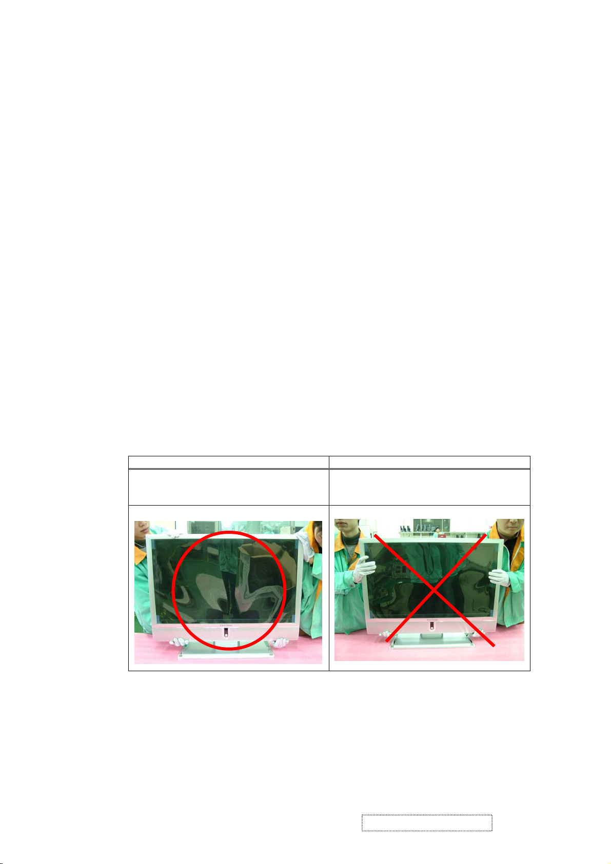
2. Handling and Placing Methods
Correct Methods: Incorrect Methods:
Only touch the metal frame of the LCD panel
or the front cover of the LCD TV. Do not touch
the surface of the polarizer.
Surface of the LCD panel is pressed by fingers
and that may cause “Mura”
ViewSonic Corporation Confidential
2
-
Do Not Copy N3250w-G
Page 6
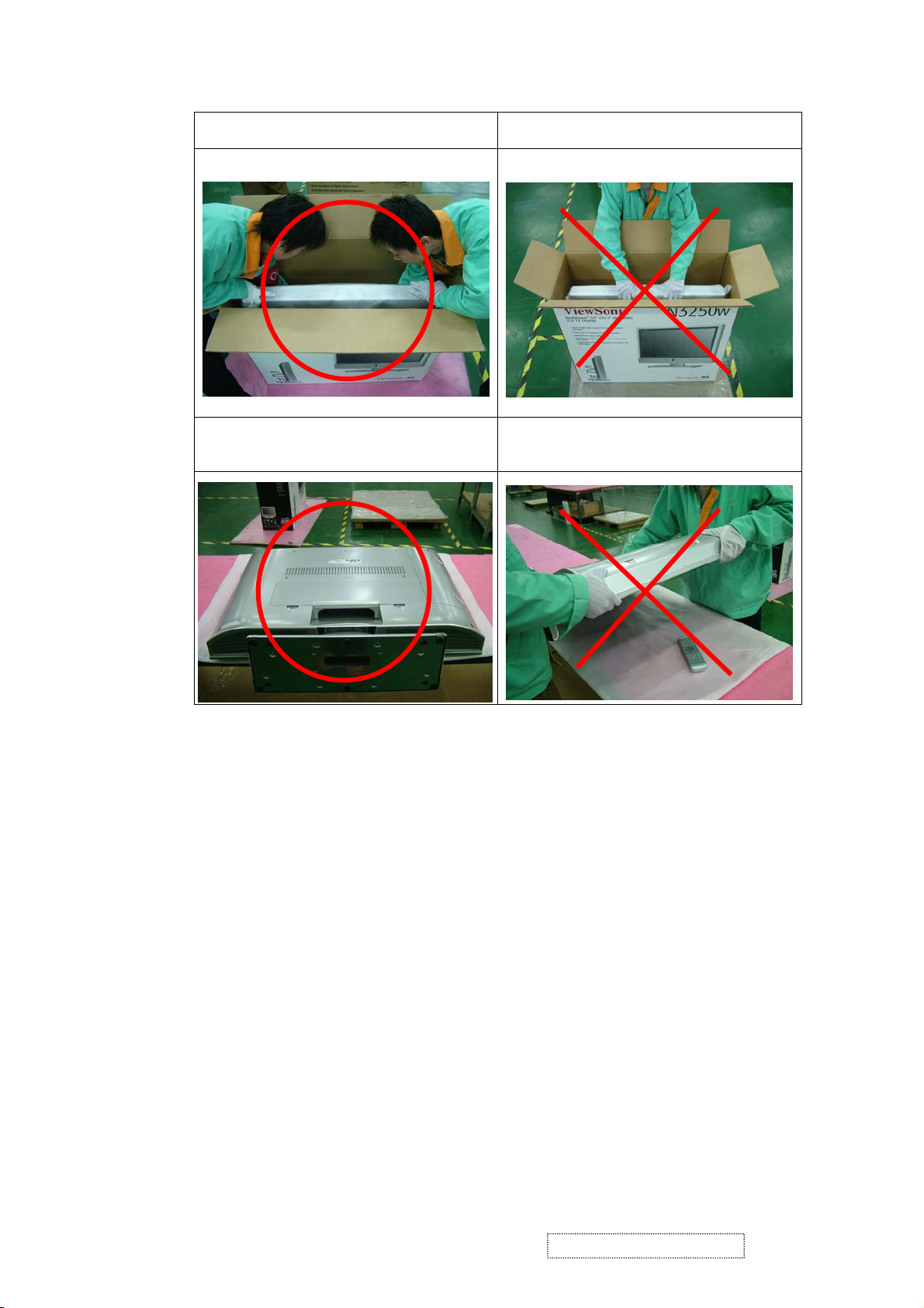
Take out the LCD TV with cushions Taking out the LCD TV by grasping the LCD
panel. That may cause “Mura”
Place the LCD TV on a clean and soft foam
pad.
Placing the LCD TV on foreign objects. That
could scratch the surface of the panel or cause
“Mura”
ViewSonic Corporation Confidential
3
-
Do Not Copy N3250w-G
Page 7

2. Service Tool & Equipment Required
1. SIGNAL GEN.
2. MULTIMETER
3. OSCILLOSCOPE
4. SCREW DRIVER
5. IRON
6. ABSORBER
7. SOLDER
8. DUMMY LOAD (5A/200W)
9. DVD PLAYER
3. SPECIFICATIONS
3.1. PRODUCT SPECIFICATIONS
LCD Panel 32" TFT
Power Management < 5W
(OFF MODE)
Displayable Resolution VESA 1280×1024 max.
Pixel Dimension 0.51075(H)×0.5107 (W)mm
LCD Display Color 16.7M Color Max. (8bit/color)
Viewing Angle CR
Horizontal: -85°+85°
Vertical: -85°+85°
Contrast Ratio 800 : 1 (typical)
Brightness 500 cd/m
Response Time Tr: 8 ms , Tf: 8ms (typical)
Active Display Area 679.68mm×392.26mm
RF Tuner Input level: 0 ~ +15 dB mV
Rang: NTSC 55.25 to 801.25 MHz, 2-69 channels for Off-Air
and 2-125 Channeis for CATV
Power Voltage: 100~240 V
Consumption: 200 Watts (Max.)
Speaker 10W×2
Compliance FCC,UL
Temperature Operating : 0°C~ +40°C
Storage : -20°C~+60°C
≥
10
2
(typical)
ViewSonic Corporation Confidential
4
-
Do Not Copy N3250w-G
Page 8
3.2. FACTORY SUPPORTING
MODES
ITEM 1 2 3 4
TIMING 640×480 60HZ 640×480 75HZ 800×600 60HZ 800×600 75HZ
Pixel Rate 25.175MHZ 31.500MHZ 40.000MHZ 49.500MHZ
H TOTAL 31.778us 26.667us 26.400us 21.333us
H DISPLAY 25.422us 20.317us 20.000us 16.162us
H B-Porch 1.907us 3.810us 2.200us 3.232us
H Width 3.813us 2.032us 3.200us 1.616us
H Border 0.318us 0.000us 0.000us 0.000us
V TOTAL 16.683ms 13.334ms 16.579ms 13.333ms
V DISPLAY 15.253ms 12.800ms 15.840ms 12.800ms
V B-Porch 1.049ms 0.427ms 0.607ms 0.448ms
Vs Width 0.064ms 0.080ms 0.106ms 0.064ms
V Border 0.254ms 0.000ms 0.000ms 0.000ms
H/V Sync -/- -/- +/+ +/+
Interlace No. No. No. No.
ITEM 5 6 7 8
TIMING 1024×768 60HZ 1024×768 75HZ 1280×720 60HZ 1280×768 60HZ
Pixel Rate 65.000MHZ 78.750MHZ 74.250MHZ 65.000MHZ
H TOTAL 20.677us 16.660us 22.222us 20.677us
H DISPLAY 15.754us 13.003us 17.239us 15.754us
H B-Porch 2.462us 2.235us 2.936us 2.462us
H Width 2.092us 1.219us 1.007us 2.092us
H Border 0.000us 0.000us 0.000us 0.000us
V TOTAL 16.666ms 13.328ms 16.667ms 16.666ms
V DISPLAY 15.880ms 12.795ms 16.000ms 15.880ms
V B-Porch 0.600ms 0.466ms 0.444ms 0.600ms
Vs Width 0.124ms 0.050ms 0.111ms 0.124ms
V Border 0.000ms 0.000ms 0.000ms 0.000ms
H/V Sync -/- +/+ -/- -/Interlace No. No. No. No.
ViewSonic Corporation Confidential
5
-
Do Not Copy N3250w-G
Page 9
ITEM 9 10 11 12
TIMING
Pixel Rate
H TOTAL
H DISPLAY
H B-Porch
H Width
H Border
V TOTAL
V DISPLAY
V B-Porch
Vs Width
V Border
H/V Sync
Interlace
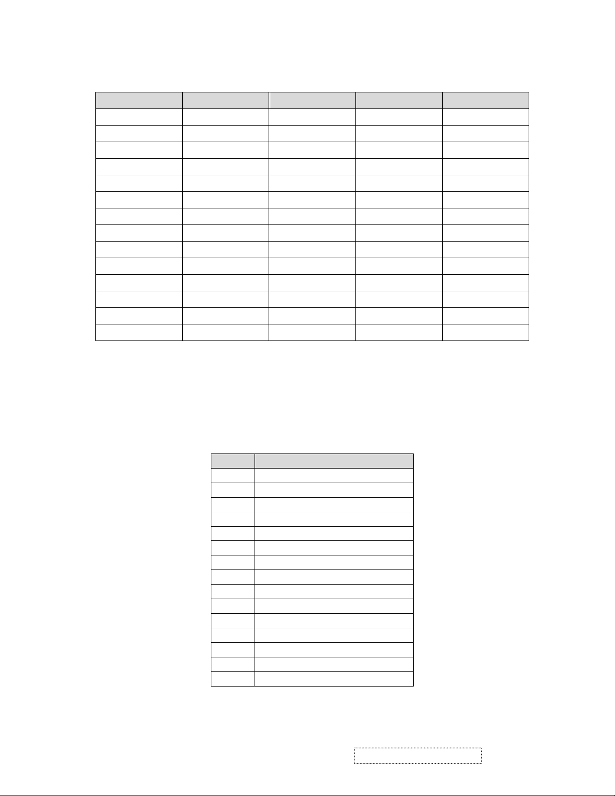
3.3. D-SUB & DVI CONNECTOR
Connector pin assignments for VGA cable
The signal cable connector shall be a molded-over, shield twisted pair cable. The cable shall be
1.8 meters long. The pin assignments shall be listed as below:
1360×768 60HZ 1280×1024 60HZ
85.5MHZ 108MHZ
20.959us 15.630us
15.906us 11.852us
2.994us 2.296us
1.310us 1.037us
0.000us 0.000us
16.662ms 16.661ms
16.097ms 16.005ms
0.377ms 0.594ms
0.126ms 0.047ms
0.00ms 0.00ms
+/+ +/+
No. No.
PIN D-SUB Connector
1 Red Video
2 Green Video
3 Blue Video
4 NC
5 GND
6 GNC
7 GND
8 GND
9 +5V for DDC
10 GND
11 NC
12 SDA
13 H-sync
14 V-sync
15 SCL
ViewSonic Corporation Confidential
6
-
Do Not Copy N3250w-G
Page 10
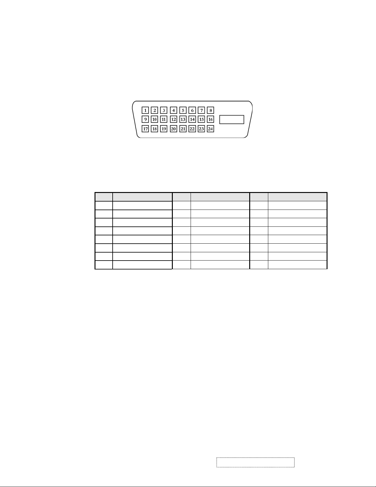
Connector pin assignments for DVI cable
DVI: 25 pins DVI connector is designed to match with DVI digital signal cable, the pin
assignment is as the following:
* 25 pins DVI female
Pin Signal Assignment Pin Signal Assignment Pin Signal Assignment
1 TMDS RX2- 9 TMDS RX1- 17 TMDS RX02 TMDS RX2+ 10 TMDS RX1+ 18 TMDS RX0+
3 TMDS Ground 11 TMDS Ground 19 TMDS Ground
4 Floating 12 Floating 20 Floating
5 Floating 13 Floating 21 Floating
6 DDC Clock 14 +5V Power 22 TMDS Ground
7 DDC Data 15 Ground 23 TMDS Clock+
8 Floating 16 Hot Plug Detect 24 TMDS Clock-
ViewSonic Corporation Confidential
7
-
Do Not Copy N3250w-G
Page 11
4. Adjustment Procedure
4.1. ADJUSTMENT CONDITIONS AND PRECAUTIONS
1. Approximately 30 minutes should be allowed for warm up before proceeding.
2. Adjustments should be undertaken only on those necessary elements since most of them
have been carefully preset at the factory.
3. ESD protection is needed before adjustment.
4.2. MAIN ADJUSTMENTS
NO. FUNCTION DESIGNATION
1. EEPROM Initial Function Key
2. White Balance Function Key
4.3. ALIGNMENT PROCEDURES
Adjustment Conditions and Precautions:
(A). Power supply voltage:
AC 110/120V±10% 60 Hz±5%, AC 220/240V±10% 50 Hz±5%.
(B). Warm up time:
The display must be power ON for at least 30 minutes at full white pattern before
starting alignments.
This is especially critical in color temperature and white balance adjustments.
(C). Signals: reference the front detail specifications and timing table.
Video : reference the front detail specifications.
1. EEPROM Initial:
A. Timing : 1024x768@60Hz.
B. Pattern : Cross hatch.
C. Switch off the power and press the “▲” and “enter “ key simultaneously, and switch
on the power. At this time we can enter into the factory mode.
D. Select the “EEPROM INIT” item and press “enter“key to reset the EEPROM.
2. White Balance Adjustment :
A. Timing : 1024x768@60Hz.
B. Pattern : 16 gray.
C. Set CA110 color analizer at the center of screen and along a perpendicular to the
screen at 20cm from the display.
D. Press menu key select the OSD page on INPUT SELECT and select MAIN:VGA.
E. Press menu key change the OSD page to adjust page.
F. Press “▼” key to select the “ WHITE BALANCE” item in the factory mode and
press “enter “key, then the white balance will be auto dadjusted .
G. Color temperature verification :
Warm /SRGB x=0.313±0.03 y=0.329±0.03
USER x=0.283±0.03 y=0.298±0.03
COOL x=0.271±0.03 y=0.278±0.03
Y≥380 cd/m
2
ViewSonic Corporation Confidential
8
-
Do Not Copy N3250w-G
Page 12
4-4 Adjusting Procedure
1. Function Test
1.1. Product
- 32” LCD TV
1.2. Test Equipment
-PC signal generator: CHROMA 2130,2135,2325,2326 or 2525.
-TV, Video signal generator: SHIBASOKU TG91CC.
-AV, S-Video, HD, and SCART signal generator: DVD.
-Color analyzer: MINOLTA CA110.
-Power meter: CP-310A or CP-320A.
1.3. Test Condition
Before function test and alignment, each LCD TV should be run-in and warmed up for at least
30 minutes with the following conditions:
(a) In room temperature,
(b) With full-white screen, and 16 grey scale,
(c) With cycled display modes.
1.4. Test Display Modes & Pattern
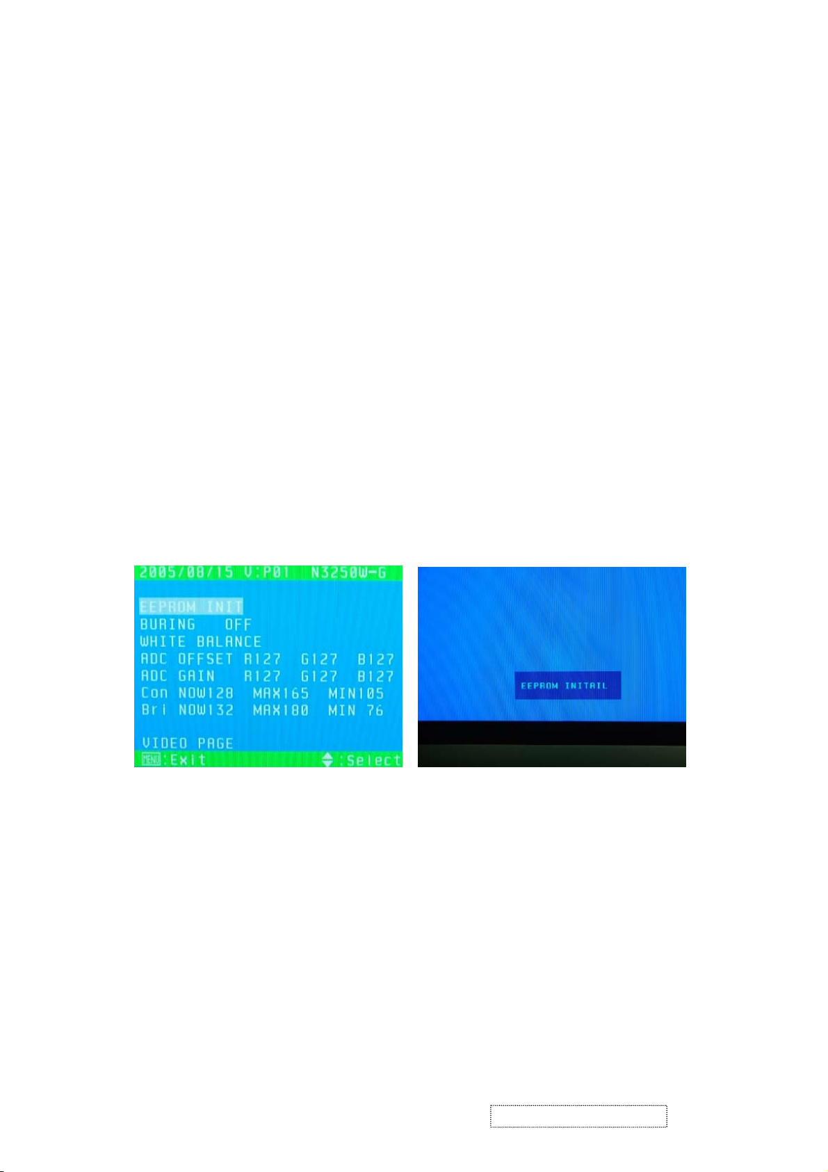
1.4.1 EEPROM INIT
A. Timing: 1366*768@60Hz
B. Pattern: 16*12 pane
C. Press ’POWER’, ‘▲’and ‘ENTER’ at the same time, then go into the FACTORY
MODE.
ViewSonic Corporation Confidential
Fig.1 Fig.2
D. Figure 1,press ENTER, and the Fig. 2 come out. The act of EEPROM INITIAL is
completed when EEPROM INIT disappeared. And remove OSD to WHITE BALANCE.
1.4.2 COLOR TEMPERATURE ADJUSTING
PC MODE:
A. Timing: 1280*1024@75Hz.
B. Pattern: 16 grey scale and full white.
C. LCD TV should be run-in and warmed up for at least 30 minutes.
D. Make sure the distance between SENOR of the CA110 and the LCD TV is about
20cm.
E. Color Temperature adjusting.
9
-
Do Not Copy N3250w-G
Page 13
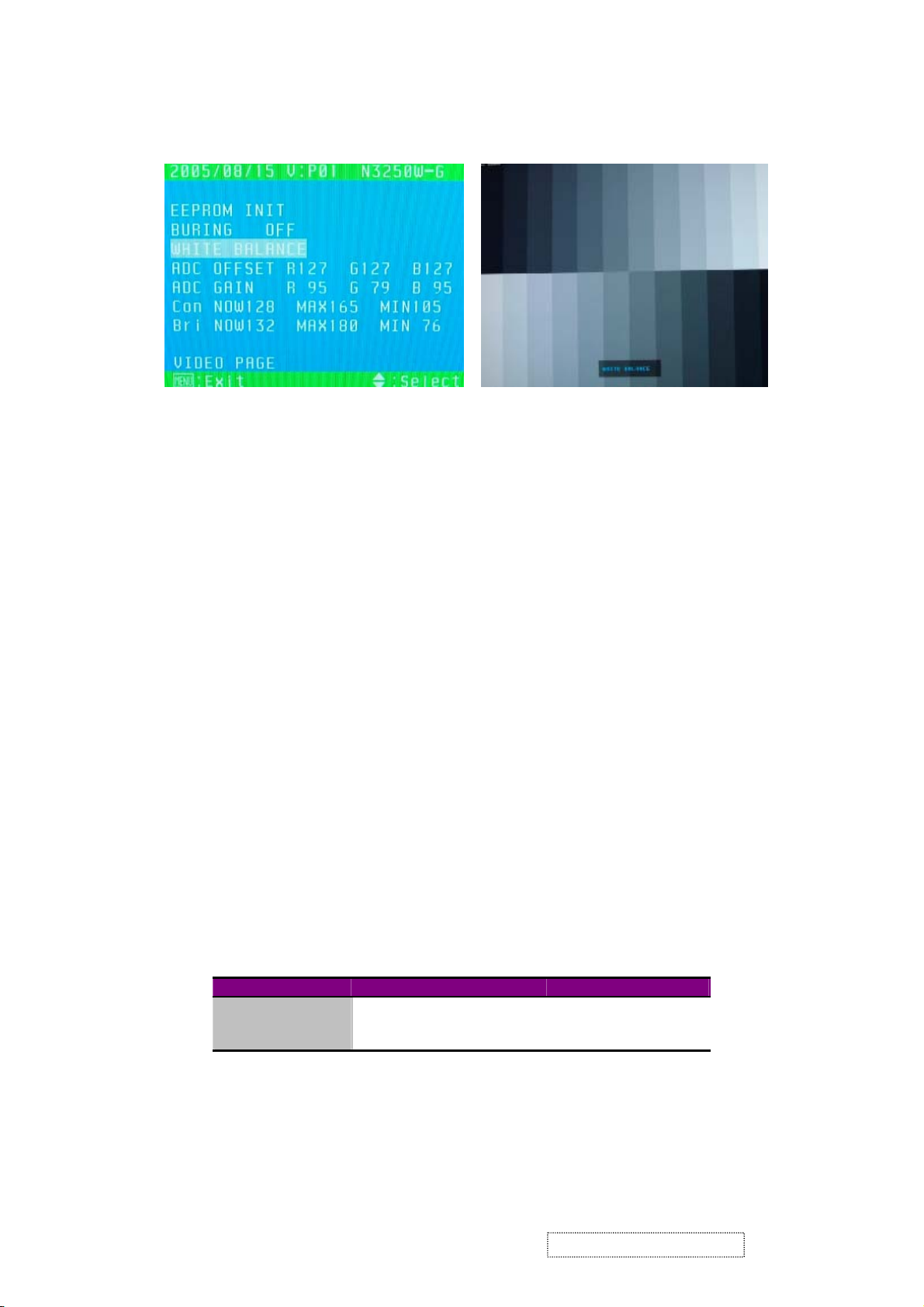
Fig. 3 Fig. 4
1. Fig. 3: under the picture of 16 grey scale, select WHITE BALANCE and press
ENTER, The color warm will auto adjust, the same as Fig. 4. The act of EHITE
BALANCEL is completed when EHITE BALANCEL disappeared.
2. After adjusting, switch to FULL WHITE and check the value of each color.
Preset color for N3250W(G)
USER----9300 x=0.285±0.015 y=0.293±0.015
Warm SRGB----6500 x=0.313±0.015 y=0.329±0.015
COOL----12000 x=0.271±0.015 y=0.278±0.015
HD MODE:
A. Timing: PAL OR NTSC.
B. Pattern: Color bar
1. Figure 3: under the picture of color bar , select WHITE BALANCE and press
ENTER, The color warm will auto adjust, the same as Figure 4. The act of EHITE
BALANCEL is completed when EHITE BALANCEL disappeared.
2. Normal----9300 x=0.285±0.015 y=0.293±0.015
Warm ----6500 x=0.313±0.015 y=0.329±0.015
COOL----12000 x=0.271±0.015 y=0.278±0.015
1.4.3.Check the position of the picture displayed and phase auto adjusting.
A. Under TV Mode, check the picture of GREY, if there are some white point flashes or
blue point, please adjusts DDR-ADJUST to normal state.
B. Depend on the TIMING of TIMING TABLE (Engineer Spec. ) to switch MODE in
order, stay about 10 seconds each MODE, it can changed and stored automatically
each MODE. We can’t switch over to the next MODE until AUTO ADJUST
disappears.
C. Need confirm after adjusting, each MODE really change and store.
1.4.4.POWER SAVING TEST:
A. Timing: 640*480@75Hz.
B. Pattern: TEST-TTL/ECL.
C. BRIGHTNESS=MAX, CONTRAST=MAX.
D. The power that each MODE consumes is shown in Chart 1.
MODE
NORMAL
Standby
OFF
MAX POWER CONSUMED POWER LED COLOR
<200W GREEN
<5W ORANGE
<5W RED
Chart 1
ViewSonic Corporation Confidential
10
-
Do Not Copy N3250w-G
Page 14

1.4.5 OSD FUNCTION TEST:
A. Timing: 640*480 @75Hz.
B. Pattern: “GENERAL-1”.
C. Make sure that Each FUNCTION have one right action.
D. After adjusting and confirming no error, we can take delivery of goods until it set as
default.
1.4.6 Under PC MODE, input PC AUDIO signal, determines whether the action of AUDIO IN is
right. Meets earphone with the EARPHONE, Determined whether the action of AUDIO
OUT is normal.
CHANNEL
ORDER
P0
P1
P2
P3
P4
P5
P6
P7
Sound modulation: standard.
2. Stereo content setting: Left sound track 3KHz; Right sound track 1KHz.
FREQUENCE
(MHz)
45.75 PAL I Mono Scope FM Mono
55.75 SECAM L Color Bar Nicam
160.00 SECAM L Mono scope FM Mono*1
440.25 PAL D/K Full White
471.25 PAL B/G Dem Nicam
567.25 PAL I Multi-Burst Nicam Dual -10 Dual Function
855.25 PALB/G Color Bar Nicam
863.25 PAL D/K Mono Scope FM Mono*1
Note: 1. Sound working pattern: Int Osc 400Hz;
1.4.7.TV RECEIVING TEST:
P0. Examines sound by ear, whether the sound does have mechanical resonation and the
electrical unusual sound, and image to sound disturbance.
P1. Examines whether the sound does receive the image disturbance, Judgment basis:
Whether there is unusual sound, input signal LEVEL<=36dBu,and STEREO
SENSITIVITY is normal.
P2. Adjustment attenuator, If the critical point of the change of the image signal to noise
ratio is under LEVEL<=60dBu,regards as normally.
P3. Examines TV brightness; confirm whether DUAL FUNCTION is normal under DUAL
MODE: whether DUAL SENSITIVITY is normal when input signal is under
LEVEL<=36dBu.
P4. Examines whether PAL color demodulation is normal by using DEM image; whether
STEREO SENSITIVITY is normal when input signal is under LEVEL<=36dBu.
P5. Examines whether DUAL FUNCTION is normal under DUAL MODE; whether
DUAL SENSITIVITY is normal when input signal is under LEVEL<=36dBu.
P6. Examines whether the sound does receive the image disturbance, Judgment basis:
Whether there is unusual sound, input signal LEVEL<=36dBu,and STEREO
SENSITIVITY is normal.
P7. Adjustment attenuator, If the critical point of the change of the image signal to noise
ratio is under LEVEL<=60dBu,regards as normally.
Broadcasting
System
PATTERN SOUND P/S(dB) CONTENT
100%
SET CONTENT CHECK
-5 Mechanical
(Sweep Tone)
-16 image to sound
Stereo*2
-16 NOISE LIMITED
(400Hz)
Nicam
Stereo*2
Stereo*2
Stereo*2
(400Hz)
Chart 2
-10 sound image
-10 Stereo Function
-16 Mechanical
-16 NOISE LIMITED
electrical unusual
sound
disturbance
SENSITIVIY
brightness effect
electrical unusual
sound
SENSITIVIY
ViewSonic Corporation Confidential
11
-
Do Not Copy N3250w-G
Page 15

1.4.8.VIDEO RECEIVING TEST:
AV receives supply oscillator: AV/S-Video/HD/SCART1/SCART2/SCART-SV are from
DVD to LCD TV; Examines whether has the image and the sound and is normal.
(1). AV: Video cable (Yellow), Audio cable (Left (White), Right (Red) sound track).
(2). S-Video: S-Video signal cable (White), Audio cable (Left (White), Right (Red) sound
track).
(3). HD (Ypbpr/YcbCr): brightness signal cable (Green), Component signal cable (Red,
Blue), Audio cable (Left (White), Right (Red) sound track).
(4). SCART1: 21Pin SCART signal cable (Black).
(5). SCART2: 21Pin SCART signal cable (Black).
1.4.9.VIDEO/AUDIO OUTPUT TEST:
(1). SCART/AV output: A 32” LCD TV in AV pattern, inputs the CVBS signal; the output
meets SCART, SCART connects another 32” LCD TV which is in SCART pattern,
Examines two 32” LCD TV whether demonstrates the same image. But their sound
doesn’t mutually affect, Must respectively adjust volume to examine sound. AV output
test method is in the same way.
(2). Under any pattern except PC pattern, The Audio output meets active extra speaker,
examines whether the extra speaker makes the sound.
1.5 Compatible Mode Table
All timings must be properly PHASED, SIZED, and CENTERED.
Aspect Ratio=Resolution to which the native signal is SCALED and CENTERED
1:1=Centered,1:1 Pixel Correlation, No Scaling. No Filtering, Image must be properly phased.
Full Screen=The Input timing is scaled to full screen, regardless of scaling artifacts.
=>640*480
N/A=Not Applicable to a green timing.
MODE
RF(Analog)
576i
576p
HD 720p
HD 1080i
640*480@60Hz
640*480@75Hz
800*600@60Hz
800*600@75Hz
1024*768@60Hz
1024*768@75Hz
1280*720@60Hz
1280*768@60Hz
1360*768@60Hz
1280*1024@60Hz
CVBS SVHS YCBCR
(scart CVBS)
NO NO NO NO NO NO YES
YES YES YES YES NO YES NO
NO NO NO YES NO YES NO
NO NO NO YES NO YES NO
NO NO NO YES NO YES NO
NO NO NO NO YES YES NO
NO NO NO NO YES YES NO
NO NO NO NO YES YES NO
NO NO NO NO YES YES NO
NO NO NO NO YES YES NO
NO NO NO NO YES YES NO
NO NO NO NO YES YES NO
NO NO NO NO YES YES NO
NO NO NO NO YES YES NO
NO NO NO NO YES YES NO
Chart 3. Mode Compatibility Table---N3250W(G)
YPBPR
(scart RGB)
RGB
(D-Sub)
HDMI
(HDCP)
TV
ViewSonic Corporation Confidential
12
-
Do Not Copy N3250w-G
Page 16

MODE
576i**
576p**
HD 720p
HD 1080i
640*480@60Hz
640*480@75Hz
800*480@60Hz
800*600@75Hz
1024*768@60Hz
1024*768@75Hz
1280*720@60Hz
1280*768@60Hz
1360*768@60Hz
1280*1024@60Hz
Chart 4. ASPECT RATIO CONTROLS (YPBPR/RGB/HDCP Only): Viewing Window
1.6 All Modes Reset
After final QC step, we have to erase all saved changes again and restore the factory defaults.
You should do “All Mode Reset” again.
Power Off LCD TV.
Turn off the LCD TV by pressing “Power” button.
1:1 FS FA R
N/A 1366*768 1024*768*
N/A 1366*768 1024*768*
1250*700 1366*768 N/A
N/A 1366*768 N/A
N/A 1366*768 1024*768*
N/A 1366*768 1024*768*
800*600 1366*768 1024*768*
800*600 1366*768 1024*768*
1024*768* 1366*768 N/A
1024*768* 1366*768 N/A
1280*720* 1366*768 N/A
1280*768* 1366*768 N/A
1360*768* N/A N/A
N/A 1366*768* N/A
(on1366*768 panel)---N3250W(G)
*=Default Setting,**=These modes also woke on CVBS/SVHS/YCBCR inputs
ViewSonic Corporation Confidential
13
-
Do Not Copy N3250w-G
Page 17
2. Firmware Upgrade Procedure
N3250W(G) LC
When you receive the returned LCD TV, please check whether the firmware version is the
latest. If not, please do the following procedures to upgrade it to the latest version.
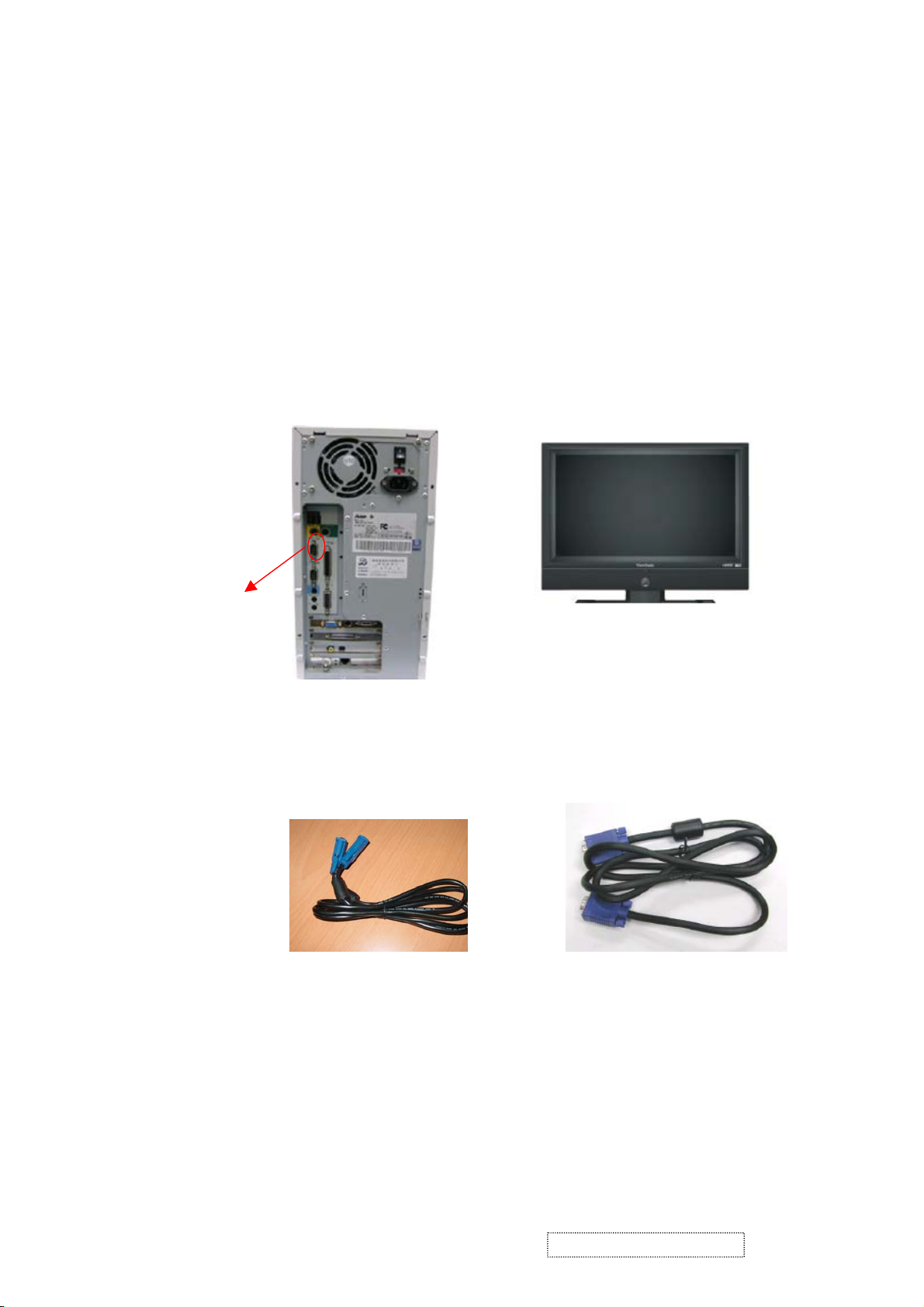
2.1. Equipment Needed
- N3250W(G) LCD TV
- Fixture for Firmware Upgrade
- VGA Cable
- PC (Personal Computer)
- LPT Cable
- Firmware Upgrade Program
- One additional LCD TV for checking the program execution
Com Port
RS-232 Cable (pin to pin)
D TV
VGA Cable
ViewSonic Corporation Confidential
14
-
Do Not Copy N3250w-G
Page 18
2.2. Setup Procedure
2.2.1 Connect P2 of Fixture with printer port of PC by LPT Cable.
2.2.2 Connect P1 of Fixture with N3250W(G) LCD TV by VGA Cable.
2.2.4 Connect Power Cord to N3250W(G) LCD TV.
2.2.5 Connect PC to the additional LCD TV.
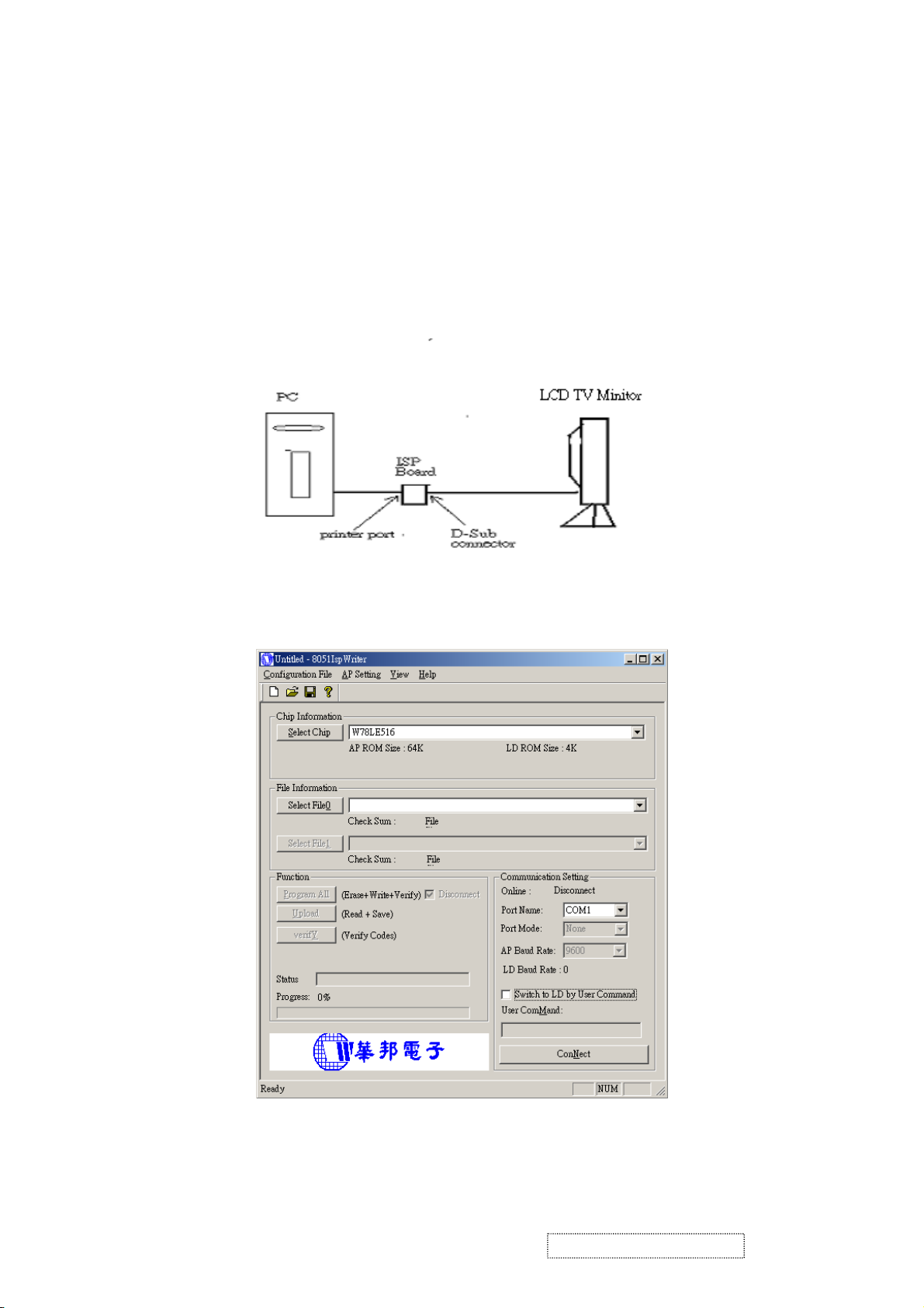
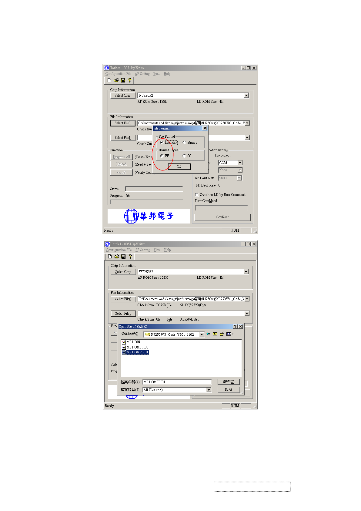
2.3. ISP Download program procedure
2.3.1 Hardware Connect status:
2.3.2 Download ISP program
Step 1: Execute ISP.exe
ViewSonic Corporation Confidential
15
-
Do Not Copy N3250w-G
Page 19
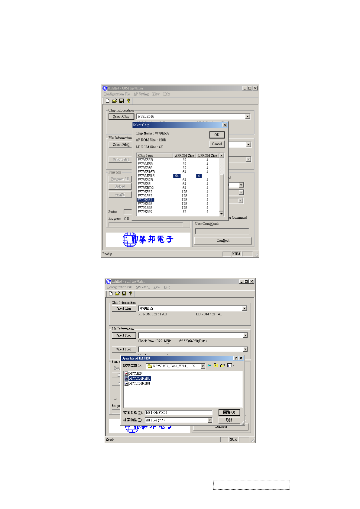
Step 2: Select MCU type
Pressing the Comb box to select the type of the MCU, It need to be selected the
N3250W(G) LCD TV for this project., then press the OK Button.
Step 3: Load file
Press the Load MCU File button to select the file (File 0
(*.Hex)
and File 1) will be downloaded.
ViewSonic Corporation Confidential
16
-
Do Not Copy N3250w-G
Page 20
ViewSonic Corporation Confidential
17
-
Do Not Copy N3250w-G
Page 21
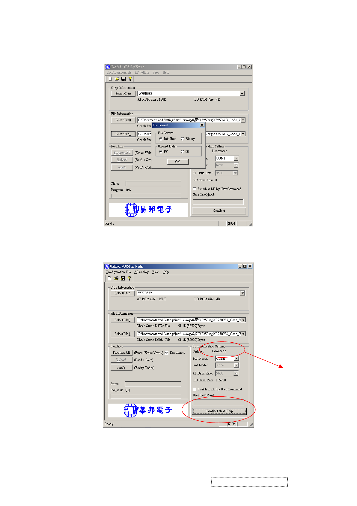
Step 4: Test Communication
Pressing the ConN
ect button to test whether the communication is well.
Testing Result
ViewSonic Corporation Confidential
18
-
Do Not Copy N3250w-G
Page 22
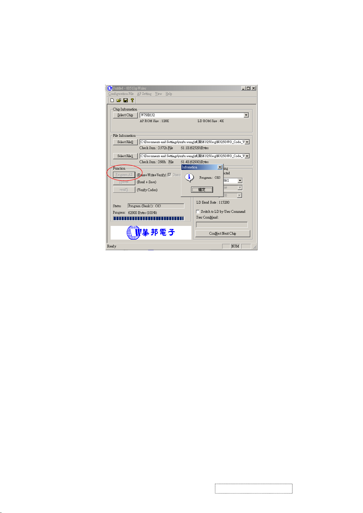
Step 5: Run
Pressing the Program All to start download program. Pressing the ‘OK’ Button to finish the
download program procedure.
Trouble shooting:
If you find the status like the follow picture. Please check the following item.
a. The connecting status between PC and ISP board.
b. The connecting status between ISP status and LCD TV.
Turn off the power of LCD TV (AC plug off) and disconnect the D-Sub connector. To connect
the D-Sub connector and then turn on the power of LCD TV.(AC plug on)
ViewSonic Corporation Confidential
19
-
Do Not Copy N3250w-G
Page 23

If the test result shows “Connected,” it means the connection is well. If not (failed),
it means the connection has problems. Then you need to check the setup procedure
or reboot the PC, or simply use another PC to do the firmware upgrade.
ViewSonic Corporation Confidential
20
-
Do Not Copy N3250w-G
Page 24

3. DDC Key In Procedure
Note:
1. Every time after replacing the main board, you have to do the DDC key in.
2. If you find the DDC does not conform to the LCD TV, you have to do the DDC key in.
3.1. Equipment Needed
- N3250W(G) LCD TV
- DDC Card
- PC
- RS232 cable
- Barcode Reader
- VGA Cable
N3250W(G) LCD TV DDC Card PC
RS-232 Cable VGA Cable Barcode Reader
ViewSonic Corporation Confidential
21
-
Do Not Copy N3250w-G
Page 25

3.2. Setup Procedure
3.2.1 Connect VGA Card and DDC Card with RS-232 cable.
3.2.2 Barcode Reader connect with keyboard and PC keyboard port.
3.2.3 Connect RS-232 Cable and N3250W(G) LCD TV with VGA Cable.
(when key in DVI DDC information, use VGA transform to DVI port )
3.2.4 Connect Power Cord to N3250W(G) LCD TV.
3.3. DDC Key In Procedure
3.3.1 Run DDC.exe
3.3.2 Choose model number and conform the Time then Press “ENTER” key.
ViewSonic Corporation Confidential
22
-
Do Not Copy N3250w-G
Page 26

3.3.3 When appear the PIC “ choose DDC Card”, Press ALT+2 Enter DDC 2B test
interface.
3.3.4 Press F8 to choose corresponding model.DAT (N3250W-G.DAT press “ENTER” key)
Choose DDC Card
ViewSonic Corporation Confidential
23
-
Do Not Copy N3250w-G
Page 27

3.3.5 Press F9 enter the download interface
3.3.6 Key in the serial number or use the barcode reader to scan the barcode of the LCD TV,
and press “ENTER” key.
ViewSonic Corporation Confidential
24
-
Do Not Copy N3250w-G
Page 28

3.3.7 The successful picture is as follows. “Compare EDID:OK! Press any key to continue”.
3.4. Check Method
Use ViewSonic EDID Editor
ViewSonic Corporation Confidential
25
-
Do Not Copy N3250w-G
Page 29

Connect the N3250W(G) LCD TV to PC with VGA Cable. Excute the EDID Editor, then
Press Ctrl+F5. If the DDC is correct, you can see the information as follow:
ViewSonic Corporation Confidential
26
-
Do Not Copy N3250w-G
Page 30

5. Packing For Shipping And Disassembly Procedure
Packing For Shipping
1. Packing Procedure
1.1 Paste protection film to protect the LCD TV. (Figure 1)
1.2 Put the LCD TV in the PE bag and seal the bag. (Figure 2)
1.3 Put the cushions on the LCD TV. (Figure 3)
1.4 Place the LCD TV into the carton and then Put the other cushions on the LCD TV,put all the
accessories into the carton. At last, close the carton and seal it with tape. (Figure 4)
Figure 1 Figure 2
1.Power Cord 2.VGA Cable 3.SCART Cable
4.RCA Cable 5.User’s Guide 6.Remote contrl
7. GUARANT CARD 8.BATTERY
ViewSonic Corporation Confidential
Figure 3
27
Figure 4
-
Do Not Copy N3250w-G
Page 31

Disassembly Procedure
1. Disassembly of Stand and Dust Cover from LCD TV.
1.1 Unscrew 4 screws that secure Stand Unit.
1.2 Detach Stand Unit from the LCD TV.
Stand
ViewSonic Corporation Confidential
28
-
Do Not Copy N3250w-G
Page 32

1.3 Detach Dust Cover from the LCD TV.
Dust Cover Dust Cover
2. Disassembly of Rear Cover.
2.1 Unscrew 16 screws to remove Rear Cover.
Rear Cover
ViewSonic Corporation Confidential
29
-
Do Not Copy N3250w-G
Page 33

3. Disassembly of Main Board, Power Board, Keypad,IR Board,Speaker,Front
Cover and Panel Unit.
3.1 Unscrew 14 screws to remove Shielding Plate.
Shielding Plate
3.2. Unscrew 3 screws to remove Dust Cover.
ViewSonic Corporation Confidential
30
-
Do Not Copy N3250w-G
Page 34

3.3. Unscrew 3 screws to remove Metal Fittg.
3.4. Unscrew 10 screws to remove Metal Fittg.
ViewSonic Corporation Confidential
31
-
Do Not Copy N3250w-G
Page 35

3.5. Unscrew 4 screws and disconnect the wires to remove Main Board.
3.6. Unscrew 6 screws and disconnect the wires to remove Power Board.
Main Board
3.7. Unscrew 6 screws and disconnect the wires to remove KeyPad.
Power Board
ViewSonic Corporation Confidential
32
-
Do Not Copy N3250w-G
Page 36

3.8. Unscrew 8 screws to remove Speaker.
3.9. Unscrew 6 screws to remove
Bracket.
Keypad Board
Speaker
ViewSonic Corporation Confidential
33
Bracket
-
Do Not Copy N3250w-G
Page 37

3.10. Unscrew 6 screws to remove Front Cover.
Front Cover
3.11. Unscrew 4 screws to remove IR Board.
IR Board
3.12. Lay Panel Unit facedown and unscrew 6 screws on its right and left sides, to remove Panel Unit
and Panel Bracket.
Panel Bracket
Panel Unit
ViewSonic Corporation Confidential
34
-
Do Not Copy N3250w-G
Page 38

6. Troubleshooting Flow Chart
11.1. NO POWER
START
Check
P118 pin 5,6
Is 12v?
YES
Check I113
is working?
YES
Check p711
pin 5 is 5v?
NO
NO
NO
Remove p118
Check 12v & 5v
Replace
X103,I114,I113
Check wireharness
p703
NO
Replace Power
Board
YES
Replace IR board
ViewSonic Corporation Confidential
35
-
Do Not Copy N3250w-G
Page 39

TV model
Check
I118 pin 14
NO
Replace I118
SCART
Check I127
pin 44,45
Check I127
pin20,21
SCART1
NO
SCART2
NO
Check
I110 pin 9,11,12,14
C278,C279,L155,L153
Check
I110 pin 9,10,12,13
C281,C282,L159,L160
Replace I127
AV,
S-VIDEO
Check I127
pin 38,39
NO
Check R500,R501
L138,L139,C602,C603
PC
Check I127
pin 41,42
YPbPr
Check I127
pin 35,36
NO
NO
Check R498,R499
C600,C601,L136,L137
L 171,L173,R502
R503,C604,C605
Do Not Copy N3250w-G
-
11.2. NO VOICE
Yes
Check L126
12v?
Yes
Check P115
Yes
Check speaker
NO
NO
Check Power
12v
Replace I129
36
ViewSonic Corporation Confidential
Page 40

N3250w-G
TV model
Check I118 pin 12 has
signal?
Yes
NO
Replace I118
SCART
Check I107 pin 27 has
signal
Yes
Check I107 is
working?
Yes
Check I107 has output signal at
RP20,RP21
Yes
Check
P116 pin 4,5+5v?
Yes
NO
Check
I109 pin 2,6 has
signal?
NO
NO
NO
SCART1
NO
SCART2
Replace X101
Replace I101
Replace Q401
Check
I110 pin 2,4 C277
Check
I110 pin3,4 C280
S-VIDEO
Check
I107 pin 26,34 has
signal?
Yes
NO
C262,C263,R215,R217,L
Check
130,L131
AV
Check
I107 pin 27
Yes
YPbPr model
Check
I103 pin 34 has signal?
Yes
Check
I103 LVDS
signal out
Yes
NO
NO
NO
Check
I109 pin 2,4 L135
Check
C418,R339
L134
Replace
I103
py
o
C
t
No
Do
l
a
nfidenti
Co
37
11.3. NO DISPLAY
Check FFC cable & LCD
Panel
n
o
i
t
a
r
rpo
o
C
nic
So
View
Page 41

DVI D SUB YPbPr
Check power region Check led color
Refer to No Power
trouble shoot flow
chart
dark
Green
Press Power Key on/
off is ok?
yes
Press menu Key if
osd display
yes
Check I103 if RST pin81 have reset pulse
Amber
Amber&Green
n
n
yes
Check I/O cable is ok
Check X103 crystal 24MHZ if
working?
y
Check I113 reset
Check keypad pcb is
ok?
y
Check if inverter is ok
yes
Check I/O signal is in pwr
y
n
Check Reset circuit
n
Change Invert er
I113 set reset pu sle?
saying mode?
Change I113
nn
y
Check I100 crystal 14.318MHZ if working?
y
Check P116 data bus have signal
y
Check panel power 5v
y
Change LCD panel
n
Change I103
ViewSonic Corporation Confidential
38
-
Do Not Copy N3250w-G
Page 42

7. Exploded View
ViewSonic Corporation Confidential
39
-
Do Not Copy N3250w-G
Page 43

ViewSonic Model Number: VS10769-1G
EXPLODED PARTS LIST (N3250w-1G)
Rev: 1a
Serial No. Prefix: PS6
Item ViewSonic P/N Ref.P/N Q'ty
1F01 #N/A 2024268203 FRONT BEZEL ABS 94HB BLACK/PS-7604B(V.S) 1
1F02 #N/A 2054256101 ORNAMENT ABS 94HB AL-PLATE 1
1F03 #N/A 2033150600 IR COVER JC278UB PC LIMPID 476C 1
1F06 #N/A 2044266901 FUNCTION KEY JC278UB ABS 94V0 AL-PLATE PWR 1
1F12 M-SCW-0824-0285 2084730082 SCREW,BND T+ M3X8(BND T+) 4
1F22 #N/A 2071972200 METAL FITTG SECC T=1.0MM FOR AU PANEL 1
1F23 #N/A 2082740082 SCREW,BND+ M4X8(BND+) 6
1F25 #N/A 2082740082 SCREW,BND+ M4X8(BND+) 2
1F26 M-SCW-0824-0811 2080003700 SCREW,SPE 1SZZTER001A M3*6L SWR17/FZMY1 6
1F27 M-SCW-0824-0811 2080003700 SCREW,SPE 1SZZTER001A M3*6L SWR17/FZMY1 4
1F28 #N/A 2072051000 METAL FITTG-I/O SECC T=1.0MM FOR EURO 1
1F29 #N/A 2082630042 SCREW M3*4 P=0.5 3
1F30 #N/A 2072050800 METAL FITTG-I/O SECC T=1.0MM FOR EURO 1
1F31 #N/A 2082630042 SCREW M3*4 P=0.5 4
1F33 M-SCW-0824-6719 2082630062 SCREW M3X6 P=0.5 2
1F36 #N/A 2027259801 DUST COVER ABS 94HB PS-7604B FOR EURO 1
1F37 #N/A 2083730102 SCREW,BND T+ SCREW BND T+ 3
1F39 #N/A 2080040062 SCREW,SPE M4*8 PMS-3/W 1
1F40 #N/A 2061254000 SPONGE SPONGE BLACK 10*6*180MM 1
1F41 #N/A 2071800300 BRACKET,FIX 62*8*3.4 T=0.5MM WITH PVC TUBE 1
1F50 #N/A 2071972400 METAL FITTG SECC T=1.0MM VESA SUPPORT 1
1F51 #N/A 2083630068 SCREW FMS+ M3X6,M,S-TITE,F,NI 4
1F52 #N/A 2082630042 SCREW M3*4 P=0.5 14
1F54 #N/A 2084740122 SCREW,BND T+ M4X12(BND T+) 4
1F55 #N/A 2027259601 DUST COVER ABS 94HB PS-7604B 1
1F56 #N/A 2044266601 FUNCTION KEY JC278 ABS 94V0 AL-PLATE FUNCTI 1
1F57 M-SCW-0824-0285 2084730082 SCREW,BND T+ M3X8(BND T+) 2
1F58 M-SCW-0824-6719 2082630062 SCREW M3X6 P=0.5 2
1F59 M-SCW-0824-6721 2084740082 SCREW,BND T+ M4X8(BND T+) 2
1F60 #N/A 2071871400 BRACKET,FIX SECC T=2.0MM FIX ARM 1
1F61 #N/A 2086240122 SCREW,P SW+ M4*12 PSW+ 2
1F62 #N/A 2084740122 SCREW,BND T+ M4X12(BND T+) 6
1F70 #N/A 2090106700 WASHER,METAL f12xf4.5x1.5t SECC 8
1F71 #N/A 2084740122 SCREW,BND T+ M4X12(BND T+) 8
2C01 #N/A 2022262901 CABI BACK ABS 94HB PS-7604B (EURO) 1
2C12 #N/A 2082740082 SCREW,BND+ M4X8(BND+) 2
2C13 #N/A 2084740122 SCREW,BND T+ M4X12(BND T+) 2
2C14 #N/A 2082340102 SCREW,CSK+ SCREW F M4X10 (CSK+) 6
2C15 #N/A 2027259901 DUST COVER ABS 94HB PS-7604B 1
2C16 #N/A 2027260001 DUST COVER ABS 94HB PS-7604B 1
2C17 #N/A 2080005901 SCREW,SPE M6*10MM TYPE"I" NI 6
5B01 #N/A 2071871700 BRACKET,FIX JC278UB ALUMINUM PS-7604B ARM 1
5B02 #N/A 2071871601 BRACKET,FIX JC32UB SGCC T=3.0MM STAND 1
5B03 #N/A 2082340102 SCREW,CSK+ SCREW F M4X10 (CSK+) 4
5B04 PL-00003417 2028258801 STAND JC278UB ABS 94HB PS-7604B 1
5B05 M-SCW-0824-0123 2084740102 SCREW,BND T+ M4X10(BND T+) 8
5B06 #N/A 2054256201 ORNAMENT JC278UB BASE PLATE LEFT 1
5B07 #N/A 2054256301 ORNAMENT JC278UB BASE PLATE RIGHT 1
5B08 #N/A 2082750402 SCREW,BND+ M5X40,M,P,ZN-CC 4
5B09 PL-PD-0714-0113 2039819301 FOOT PAD RUBBER O20*2TMM SQUARE RAIN 6
Description
ViewSonic Corporation Confidential
40
-
Do Not Copy N3250w-G
Page 44

Components:
8. Recommended Spare Parts List
RECOMMENDED SPARE PARTS LIST (N3250w-1G)
ViewSonic Model Number: VS10769-1G
Rev: 1a
Serial No. Prefix: PS6
Item ECR/ECN ViewSonic P/N Ref.P/N Location Q'ty
Accessories:
1 AC POWER CORDCHINA WALL 1.83M BLACK A-PC-0106-0277 2427130097P P901 1
2 REMOTE CONTROL N3250W(G) ViewSonic CHINA A-00004438 2419200047P H901 1
Board Assembly:
3 PCB ASS'Y BLOCK (CON) B-00004487 6202-7032146361 1
4 PCB ASS'Y BLOCK (IR) B-00004488 6206-7032146361 1
5
Cabinets:
6 CABI BACK ABS 94HB PS-7604B (EURO) C-00004490 2022262901P 2C01 1
7 DUST COVER ABS 94HB PS-7604B C-00004491 2027259601P 1F55 1
8 DUST COVER ABS 94HB PS-7604B C-00004492 2027259901P 2C15 1
9 DUST COVER ABS 94HB PS-7604B C-00004493 2027260001P 2C16 1
10 DUST COVER ABS 94HB PS-7604B FOR EURO C-00004494 2027259801P 1F36 1
11 FRONT BEZEL ABS 94HB BLACK/PS-7604B(V.S) C-00004495 2024268203P 1F01 1
12 STAND JC278UB ABS 94HB PS-7604B PL-00003417 2028258801P 5B04 1
Cables:
13 CABLERCA 3P(Y/R/W) 2562#26 1.8M BLK CB-00003425 2427701893P P905 1
14 I/O CABLE D15/D15 20276(3+6) 1.83M BLACK A-VC-0101-0386 2427501187P P902 1
Documentation:
15 GUARANT CARD VIEWSONIC N3250W(G) QSG DC-00004496 2002310515P 6P81 1
16 GUARANT CARD VIEWSONIC WARRANTY CARD-C 2004 DC-00003461 2002310402P 6P07 1
Electronic
17
Packing Material:
18 CARTON BOX 360X220X50mm (WXDXH) BOX(B) P-00004497 2011100017P 6P85 1
19 POLYFOAM EPE (R) P-00003574 2012178700P 6P20 1
20 POLYFOAM EPE (L) P-00003575 2012178800P 6P21 1
21 POLYFOAM EPE DOWN JC328UB P-00004498 2012180100P 6P22 1
PCB ASS'Y BLOCK (MAIN)
LCD PANELT315XW01 V2 AU E-00003571 2212008100P V901 1
Description
B-00004489 6201-7032146361 1
ViewSonic Corporation Confidential
-
Do Not Copy N3250w-G
41
Page 45

ViewSonic Model Number: VS10769-1G
Universal number#
M-SCW-0824-0811
M-SCW-0824-6719
M-SCW-0824-0285
DUST COVER-RIGHT COVER
DUST COVER-DOWN COVER
M-SCW-0824-0123
LED HOLDER-PWR
MANUAL INSERT-MAIN
MANUAL INSERT-CON
C627 C686 C687
C102 C103 C106C12 C113
C491 C492 C493 C494
BOM LIST (N3250w-1G)
Rev: 1a
Serial No. Prefix: PS6
Item ViewSonic P/N Ref. P/N Location
1 C-00004495 2024268203P FRONT BEZEL 32UB ABS HB BLK C/PS-7604B(VSC 1F01 1
2 #N/A 2054256101P ORNAMENT JC32 FRONT BAR ABS HB AL-PLATE 1F02 1
3 #N/A 2033150600P IR COVER JC278UB PC LIMPID 476C 1F03 1
4 #N/A 2053754201P LED INDIC.-PWR JC278UB PMMA LIMPID 1F04 1
5 #N/A 2044266901P FUNCTION KEY JC278UB ABS 94V0 AL-PLATE PWR 1F06 1
6 #N/A 2071972200P METAL FITTG SECC T=1.0MM FOR AU PANEL 1F22 1
7 #N/A 2082740082P SCREW,BND+ M4X8(BND+) 1F23 1F25 2C12 10
8
9 #N/A 2072051000P METAL FITTG-I/O SECC T=1.0MM FOR EURO 1F28 1
10 #N/A 2082630042P SCREW M3*4 P=0.5 1F29 1F31 1F52 21
11 #N/A 2072050800P METAL FITTG-I/O SECC T=1.0MM FOR EURO 1F30 1
12 #N/A 2083630068P SCREW FMS+ M3X6,M,S-TITE,F,NI 1F32 1F51 7
13
14 C-00004494 2027259801P DUST COVER JC32 ABS HB PS-7604B (E) 1F36 1
15 #N/A 2083730102P SCREW,BND T+ SCREW BND T+ 1F37 3
16 #N/A 2080040062P SCREW,SPE M4*8 PMS-3/W 1F39 1
17 #N/A 2061254000P SPONGE SPONGE BLACK 10*6*180MM 1F40 2C02 2
18 #N/A 2071800300P BRACKET,FIX 62*8*3.4 T=0.5MM WITH PVC TUBE 1F41 1
19 #N/A 2071972400P METAL FITTG SECC T=1.0MM VESA SUPPORT 1F50 1
20 #N/A 2084740122P SCREW,BND T+ M4*12 (BND T+) 1F54 1F62 1F71 2C13 20
21 C-00004491 2027259601P DUST COVER JC32 ABS HB PS-7604B 1F55 1
22 #N/A 2044266601P FUNCTION KEY JC278 ABS 94V0 AL-PLATE FUNCTI 1F56 1
23
24 #N/A 2071871400P BRACKET,FIX SECC T=2.0MM FIX ARM 1F60 1
25 #N/A 2086240122P SCREW,P SW+ M4*12 PSW+ 1F61 2
26 #N/A 2090106700P WASHER,METAL f12xf4.5x1.5t SECC 8. 1F70 0
27 C-00004490 2022262901P CABI BACK JC32 ABS HB PS-7604B(E) 2C01 1
28 #N/A 2061254001P SPONGE SPONGE BLACK 20*15*50MM 2C03 2
29 #N/A 2061151900P FELT 267*12.7=0.5MM NO.5000NS 2C04 2
30 C-00004492 2027259901P
31 C-00004493 2027260001P
32 #N/A 2080005901P SCREW,SPE M6*10MM TYPE"I" NI 2C17 6
33 #N/A 2071871700P BRACKET,FIX JC278UB ALUMINUM PS-7604B ARM 5B01 1
34 #N/A 2071871601P BRACKET,FIX JC32UB SGCC T=3.0MM STAND 5B02 1
35 #N/A 2082340102P SCREW,CSK+ SCREW F M4X10 (CSK+) 5B03 2C14 10
36 PL-00003417 2028258801P STAND JC278UB ABS 94HB PS-7604B 5B04 1
37
38 #N/A 2054256201P ORNAMENT JC278UB BASE PLATE LEFT 5B06 1
39 #N/A 2054256301P ORNAMENT JC278UB BASE PLATE RIGHT 5B07 1
40 #N/A 2082750402P SCREW,BND+ M5X40,M,P,ZN-CC 5B08 4
41 PL-PD-0714-0113 2039819301P FOOT PAD RUBBER O20*2TMM SQUARE GRAIN 5B09 6
42 #N/A 2011132505P CARTON BOX VIEWSONIC N3250W(G) VS10769-1G 6P01 1
43 #N/A 2055632167P LABEL N3250W VS10769-1G (G) AUO 6P02 1
44 #N/A 2055636040P LABEL N3250W VS10769-1G SMALL LABEL 6P05 1
45 DC-00003461 2002310402P GUARANT CARD VIEWSONIC WARRANTY CARD-C 2004 6P07 1
46 M-LB-0813-0862 2056606025P SERIAL LABEL VS CN WARRANTY CARD SN STICKER 6P08 2
47 M-LB-0813-0984 2002201323P DISPLAY CARD VIEWSONIC CRT QUALIFIED LABEL 6P09 1
48 M-LB-0813-0856 2055613379P LABEL VIEWSONIC CONTAINER LABEL 6P11 1/6
49 M-LB-0813-0863 2056606010P SERIAL LABEL VIEWSONIC BOX STICKER-G 6P12 1
50 M-LB-0813-0530 2055617101P LABEL 10*20 HI-POT TESTED OK 6P13 1
51 M-LB-0813-0959 2055613392P LABEL VSC HIGH VOLTAGE WARNING LABEL 6P14 1
52 M-LB-0813-0864 2056606009P SERIAL LABEL VIEWSONIC SERVICE STICKER-G 6P15 1
53 #N/A 2012184000P POLYFOAM UB/EC TOP(R) EPE 6P20 1
54 #N/A 2012184100P POLYFOAM UB/EC TOP(L) EPE 6P21 1
55 #N/A 2012184200P POLYFOAM UB DOWN EPE 6P22 1
56 #N/A 2055135049P LABEL N3250W VS10769-1G AUO CHINA 6P50 1
57 M-LB-0813-0528 2055103400P LABEL JK0936F WEN 6P52 1
58 M-LB-0813-0002 2056603050P SERIAL LABEL VIEWSONIC LCD SERIAL LABEL 6P56 6P54 6P55 6P51 4
59 #N/A 2013054007P POLYETHY BAG 870*800MM HDPE BAG 6P60 1
60 #N/A 2013054013P POLYETHY BAG 950LX400WX1200H T=0.08MM 6P70 1
61 #N/A 2001131435P OWNER GUIDE VSC N3250W VS10769-1G CHINA 6P80 1
62 DC-00004496 2002310515P GUARANT CARD VIEWSONIC N3250W(G) QSG 6P81 1
63 P-00004497 2011100017P CARTON BOX 360X220X50mm (WXDXH) BOX(B) 6P85 1
64 M-MS-0808-1316 2013222536P POLYETHY BAG 250mmX350mmX0.3t ADD>PE-LD< 6P86 1
65 #N/A 2074750100P
66 #N/A 2005100400P BATTERY,DRY R6PGS 1.5V (AA) CHINA TOSHIBA B901 2
67 #N/A 2710125100
68 #N/A 2720125100 V-TYPE-MAIN N3250W(G) BA52 1
69 #N/A 2702225100 PCB-CON N3250W(G) BB31 1
70 #N/A 2710625100
71 E-C-0404-4424 2346110396P CAP,CHIP 125'C CS 0603/X7R/50V 0.01u K T
72 #N/A 2349900996P CAP,CHIP SPEC 0603V-PORT 10P+-10% INPAQ
2080003700P SCREW,SPE ISZZTER001A M3*6L MSWR17/FZMYI 1F26 1F27 1F38 16
2082630062P SCREW M3X6 P=0.5 1F33 1F58 4
2084730082P SCREW,BND T+ M3X8(BND T+) 1F57 1F12 1F59 8
2084740102P SCREW,BND T+ M4X10(BND T+) 5B05 8
Description
JC32 ABS HB PS-7604B (R) 2C15 1
JC32 ABS HB PS-7604B (D) 2C16 1
NYLON 66 H=6.0MM LED306 9R81 1
N3250(G) BA42 1
N3250W(G) BB42 1
C100 C101 C104 C424 C517
C114 C115 C119 C408 C409
C420 C421 C422 C243 C471
C472 C473 C474 C475 C490
Q'ty
8
24
ViewSonic Corporation Confidential
42
-
Do Not Copy N3250w-G
Page 46

Item ViewSonic P/N Ref. P/N Location
Universal number#
C105 C107 C108 C109 C10
C426 C427
3
CAP,MINI ELE 105'C
C125 C127 C275 C276 C277
C726 C730 C733
C126 C128 C129 C131 C133
2
CAP,MINI ELE 105'C
C135 C138 C140 C150 C152
C623 C683 C684
CAP,MINI ELE 105'C
C631 C632 C634 C635
CAP,MINI ELE 105'C
C518 C641 C703 C724 C725
4
2
4
C267 C268 C391 C640 C644
C626
C278 C279 C281 C282 C600
C682
C673C676 C734
C430 C431 C432 C433 C458
C504C505 C506
CAP,ELE LOW ESR 105'C
CAP,MINI ELE 105'C
CAP,ELE LOW ESR 105'C
CAP,MINI ELE 105'C
CAP,ARRAY P=0.8 85'C
DIODE,ZENER SMD
73 #N/A 2346147396P CAP,CHIP 125'C CS 0603/X7R/50V 0.047u K T
74 #N/A 2341112096P CAP,CHIP 125'C CS 0603/COG/50V 12p J T
75 #N/A 2336310713P
76 #N/A 2346110496P CAP,CHIP 125'C CS 0603/X7R/50V 0.1u K T
77 #N/A 2341130096P CAP,CHIP 125'C CS 0603/COG/50V 30p J T
78 #N/A 2336610613P
79 #N/A 2336322613P
80 E-00000999 2336347613P
81 #N/A 2341120096P CAP,CHIP 125'C CS 0603/COG/50V 20p J T
82 E-C-0404-3900 2341133096P CAP,CHIP 125'C CS 0603/COG/50V 33p J T
83 #N/A 2346122396P CAP,CHIP 125'C CS 0603/X7R/50V 0.022u K T
84 E-C-0404-4828 2341110196P CAP,CHIP 125'C CS 0603/COG/50V 100p J T
85 #N/A 2341147196P CAP,CHIP 125'C CS 0603/COG/50V 470p J T
86 E-00003865 2346710596P CAP,CHIP 85'C CS 0603/Y5V/16V 1.0u Z T
87 #N/A 2333610613P CAP ELE 105'C EC 10u/ 50V 5*11 P=2.5 T
88 #N/A 2349901096P CAP,CHIP SPEC AC0603470A 47p±10% INPAQ
89 #N/A 2335215811P
90 #N/A 2341110296P CAP,CHIP 125'C CS 0603/COG/50V 1000p J T C519 C638 C639 3
91 #N/A 2346415496P CAP,CHIP 85'C CS 0603/Y5V/50V 0.15u Z T C614 1
92 E-C-0404-4829 2341122196P CAP,CHIP 125'C CS 0603/COG/50V 220p J T C617 C671 2
93 #N/A 2341139196P CAP,CHIP 125'C CS 0603/COG/50V 390p J T C618 1
94 #N/A 2341168196P CAP,CHIP 125'C CS 0603/COG/50V 680p J T C625 1
95 #N/A 2341156096P CAP,CHIP 125'C CS 0603/COG/50V 56p J T C628 C629 C633 3
96 E-C-0404-4225 2346139296P CAP,CHIP 125'C CS 0603/X7R/50V 3900p K T C630 1
97 #N/A 2341182996P CAP,CHIP 125'C CS 0603/COG/50V 8.2p D T C636 C637 2
98 #N/A 2333310801P CAP ELE 105'C EC 1000u/ 16V10*17 P=5.0 C C653 C704 2
99 #N/A 2347110396P CAP,CHIP 125'C CS 0805/X7R/50V 0.01u K T C654 C666 C667 C675 4
100 #N/A 2301310591P CAP MEB MEB 1.0u/ 63V P=5.0 J T C662 C665 C670 C674 4
101 #N/A 2336610513P
102 E-C-0404-3816 2347110296P CAP,CHIP 125'C CS 0805/X7R/50V 1000p K T C688 C689N C690 C691 4
103 E-C-0404-3096 2335310812P
104 #N/A 2336622513P
105 #N/A 2340722008P
106 E-D-0403-1779 2364503996P
EC 100u/ 16V 6.3*7 P=2.5 T
EC 10u/ 50V 5*7 P=2.5 T
EC 22u/ 16V 4*7 P=2.5 T
EC 47u/ 16V 5*7 P=2.5 T
EC 1500u/ 10V10*16 P=5.0 C C514 C521 2
EC 1u/ 50V 4*7 P=2.5 T C679 C680 2
EC 1000u/ 16V 10*20 P=5.0 K C714 C719 2
EC 2.2u/ 50V 4*7 P=2.5 T C738 C643 2
1206Y5V 22.000PF 16V M 8P CP01 CP02 2
BZV55-C5V6 5% SOD-80C PHILIPS
C111 C417 C418 C419 C425
C116 C117 C118
C280 C488 C489 C713 C720
C134 C136 C137 C139 C141
C142 C143 C144 1C45 C146
C147 C148 C149 C151 C154
C155 C156 C158 C159 C160
C161 C162 C163 C165 C166
C167 C168 C169 C170 C180
C181 C182 C183 C184 C185
C186 C187 C188 C189 C190
C192 C193 C194 C195 C196
C197 C206 C207 C208 C209
C210 C212 C214 C215 C216
C217 C218 C219 C220 C221
C226 C227 C231 C234 C235
C236 C237 C238 C239 C240
C241 C244 C245 C246 C247
C252 C253 C254 C255 C256
C261 C262 C263 C270 C274
C376 C380 C382 C383 C384
C385 C386 C387 C388
C389C390 C482 C485 C513
C529 C611 C619 C620 C624
C642 C651 C660 C663 C668
C677 C765 C701 C702C712
C715 C716 C721 C722 C723
C130 C132
C153 C157 C164 C178 C204
C213 C229 C232 C379 C612
C613 C615 C616 C621 C622
C179 C191 C269 C483 C486
C205 C211 C225 C233 C381
C222 C223 C377 C378
C224 C736
C228 C230 C242 C243
C248 C249 C250 C251 C257
C258 C259 C264 C265 C266
C272 C273 C522 C608 C609
C601 C602 C603 C604 C605
C606 C607 C610 C655 C656
C657 C658 C659 C678 C681
C392 C652 C661 C664 C669
C463 C477 C479 C480 C481
C484 C487 C496 C502 C503
D100 RA
D101 RA
D104 RA
Q'tyDescription
12
13
127
23
9
10
15
6
21
8
18
3
ViewSonic Corporation Confidential
43
-
Do Not Copy N3250w-G
Page 47

Item ViewSonic P/N Ref. P/N Location
Universal number#
DIODE,ZENER SMD
DIODE,ZENER SMD
DIODE,SWITCH SMD
DIODE,RECT(SMD)
DIODE,SWITCH SMD
MEMORY IC (SDRAM)
IC,MEMORY (EEPROM)
MEMORY IC (EEPROM)
2
2
2
2
107 E-D-0403-1666 2364500396P
108 #N/A 2364505636P
109 #N/A 2364600496P
110 E-D-0403-1892 2364200896P
111 E-00003830 2364601396P
112 E-00003534 2363600696P DIODE,SWITCH RLS4148-T11 SOD-80 ROHM
113 #N/A 2363705101P LED L-3WEGW KINGBRIGHT D721 1
114 A-00004438 2419200047P CONT BLOCK N3250W(G) VinewSonic CHINA H901 1
115 #N/A 2365104000P MEMORY IC 24LC22A-I/P PDIP-8 MICROCHIP I100 1
116 E-IC-0401-2017 2365412600P DIGITAL IC 24LC21A/P PSDIP-8 MICROCHIP I101 1
117 #N/A 2365814996P IC,LINEAR(SMD) AP1084K18LA TO-263 AnaChip I102 RA 1
118 #N/A 2365810196P IC,LINEAR(SMD) AIC1084-18CM TO-263 AIC I102 RB 1
119 #N/A 2365335156P LINEAR IC OB1084CLP(1.8V) TO-263 LITEON I102 RC 1
120 #N/A 2365425096P DIGITAL IC MST5151LA-LF LQFP-256 Mstar I103 1
121 #N/A 2365104396P MEMORY IC NT5DS4M32EG FBGA-144 NANYA I105 RA 1
122 #N/A 2365105796P
123 E-IC-0401-2924 2365808196P IC,LINEAR(SMD) AP1117E33LA SOT-223 AnaChip I106 RA 1
124 #N/A 2365808396P IC,LINEAR(SMD) AIC1117-33PY SOT-223 AIC I106 RB 1
125 #N/A 2365809496P IC,LINEAR(SMD) CM1117SCM-3.3V SOT223 CHAMPION I106 RC 1
126 #N/A 2365425066P DIGITAL IC SAA7117AH QFP-160 PHILIPS I107 1
127 #N/A 2365813696P IC,LINEAR(SMD) AP1117E18LA SOT-223 AnaChip I108 RA 1
128 #N/A 2365335086P LINEAR IC AIC1117A-18PY SOT223 AIC I108 RB 1
129 #N/A 2365335216P LINEAR IC MM1501XNRE SOT-26B MITSUMI I109 1
130 #N/A 2365915796P IC,DIGITAL SMD ADG774BRQ QSOP-16 ADI I110 RA 1
131 E-00003530 2365813796P IC,LINEAR(SMD) TS5V330DBQR SSOP-16 TI I110 RB 1
132 #N/A 2365931896P IC,DIGITAL SMD FSAV330QSCX QSOP-16 FAIRCHILD I110 RC 1
133 #N/A 2365425016P DIGITAL IC W79E632A40PL PLCC-44 Winbond I113 1
134 #N/A 2365104700P MEMORY IC AT24C32A-10PU-2.7 PDIP-8 ATMEL I114 RA 1
135 #N/A 2365102800P
136 #N/A 2365105600P MEMORY IC HT24LC04 DIP-8 HOLTEK I115 RA 1
137 #N/A 2365416900P DIGITAL IC AT24C04-10PC-2.7 SOIC-8 ATMEL I115 RB 1
138 #N/A 2365105900P
139 #N/A 2416901900P UV TUNER FQ1216ME/IH-5 PHILIPS I118 RA 1
140 E-00003954 2416901800P UV TUNER TAPE-S701D (J) LG I118 RB 1
141 #N/A 2365930296P IC,DIGITAL SMD MSP3410G-QI-B8V3 Micronas I127 RA 1
142 #N/A 2365425176P DIGITAL IC MSP3410G-QI-C12-001 Micronas I127 RB 1
143 #N/A 2365335246P LINEAR IC TPA3004D2PHPRG34 HTQFP48 TI I129 1
144 E-00000915 2360501196P FET,P-CH SMD AP9435GM SO-8 APEC
145 E-00000916 2360501596P FET,P-CH SMD AO4405 SO-8 AOS
146 #N/A 2360510196P FET,P-CH SMD SI4953ADY-T1-E3 SO-8 VISHAY
147 E-00003529 2360501796P FET,P-CH SMD APM9435KC SO-8 Anpec
148 #N/A 2365813096P IC,LINEAR(SMD) L78M08CDT-TR DPAK(TO-252) ST I137 1
149 E-IC-0401-2745 2365810796P IC,LINEAR(SMD) AP1084K33LA TO-263 ATC I140 RA 1
150 E-IC-0401-2123 2365807496P IC,LINEAR(SMD) AIC1084-33PM TO-263 AIC I140 RB 1
151 #N/A 2365809196P IC,LINEAR(SMD) CM1084SCN263 SO-263 CHAMPION I140 RC 1
152 #N/A 2365811196P IC,LINEAR(SMD) AP1117E25A(2.5V)SOT223 AnaChip I141 RA 1
153 #N/A 2365811796P IC,LINEAR(SMD) GM1117-2.5ST3 SOT-223 GAMA I141 RB 1
154 #N/A 2365808596P IC,LINEAR(SMD) CM1117KCM-2.5V SOT223 CHAMPION I141 RC 1
155 #N/A 2419301400P RECEIV BLOCK ECM-A38-3VS28 ECEL I721 1
156 #N/A 2438000001P SOFTWARE HDCP KEY CODE KC01 1
RLZ5.6B 5.45-5.73V LL-34 ROHM
BZV55-B5V6 2% SOD-80C PHILIPS
MM4148 SOD-80 GRANDE
BAS32L SOD80C PHILIPS
1N4148W-7-F SOD-123 DIODES
EM6A9320BI-5MG FBGA144 Etron I105 RB 1
M24C32-WBN6P PDIP-8 ST I114 RB 1
AT24C04-10PU-2.7 PDIP-8 ATMEL I115 RC 1
D100 RB
D101 RB
D104 RB
D100 RC
D101 RC
D104 RC
D102 RA
D103 RA
D105 RA
D106 RA
D107 RA
D112 RA
D113 RA
D102 RB
D103 RB
D105 RB
D106 RB
D107 RB
D112 RB
D113 RB
D102 RC
D103 RC
D105 RC
D106 RC
D107 RC
D112 RC
D113 RC
D102 RD
D103 RD
D105 RD
D106 RD
D107 RD
D112 RD
D113 RD
I135 RA
I136 RA
I135 RB
I136 RB
I135 RC
I136 RC
I135 RD
I136 RD
Q'tyDescription
3
3
7
7
7
7
ViewSonic Corporation Confidential
44
-
Do Not Copy N3250w-G
Page 48

Item ViewSonic P/N Ref. P/N Location
Universal number#
BEAD,HI-IMPEDANCE
L132 L134L135
BEAD,HI-IMPEDANCE
1
BEAD,HI-IMPEDANCE
L104 L136 L137 L138 L139
L160 L171 L173
BEAD,HI-CURRENT
L105 L106 L107 L108 L110
L190 L191
4
BEAD,HI-CURRENT
5
2
L166 L206 R183 R193 R195
R624
INDUCTOR CHIP MULTI-LAYER
INDUCTOR CHIP MULTI-LAYER
AL SHIELDING TAPE
SHIELDING FOAM
SHIELDING FOAM
XISTOR,NPN R SMD
XISTOR,NPN R SMD
157 #N/A 2379330006P
158 #N/A 2379322106P
159 #N/A 2379360106P
160 E-00003533 2379520196P
161 #N/A 2371115001P COIL,CHOKE 15uH/ 8*10 UEW 0.5mm/21.5Ts
162 #N/A 2379500196P
163 #N/A 2371120201P COIL,CHOKE 2mH 10*15 0.3mm/231.5Ts P=5.0
164 E-R-0405-6600 2253200096P RES CHIP 1/10W RC 0603 1/10W 0 ohm J T
165 #N/A 2377410996P
166 #N/A 2377410996P
167 #N/A 2404381106P CONNECTOR 2DS-0341-001 DVI-D S.E P100 RA 1
168 #N/A 2404381104P CONNECTOR QH11121-FP0 DVI-D FOXCONN P100 RB 1
169 #N/A 2407430900P SOCKET DHSB-15FTF7 BLUE(661C) LEOCO P101 1
170 M-MS-0808-6354 2404301105P CONNECTOR JST PH 6P SIDE P=2.0 OR EQUAL P102 P711 2
171 #N/A 2404301106P CONNECTOR JST PH 7P SIDE P=2.0 OR EQUAL P103 P701 2
172 #N/A 2407442900P SOCKET MINI DIN 4P SIDE BLACK P104 1
173 #N/A 2405322201P RCA JACK 2*2P (4P BLU/YEL/RED/GRN) P105 1
174 #N/A 2405324201P RCA JACK 2*2P (WHITE/RED) P106 1
175 #N/A 2404300003P CONNECTOR JST XH 4P TOP P=2.5 OR EQUAL P107 P115 2
176 #N/A 2405322202P RCA JACK RCA JACK 2P (WHT/RED) P110 1
177 #N/A 2405105900P EARPHONE JACK ERR 3.5∮ SIDE 284C(BLUE) P111 1
178 #N/A 2404322321P CONNECTOR WRC-021V-07 21P*3.81mm KYOYAKU P112 P113 2
179 #N/A 2405106000P EARPHONE JACK 2SJ-P520-A04 (577C) SINGATRON P114 1
180 #N/A 2404322130P CONNECTOR 2R1L SIDE P=2.0mm 2046P30HT00 P116 1
181 #N/A 2404301011P CONNECTOR JST XH 12P SIDE P=2.5 OR EQUAL P118 1
182 #N/A 2407390144P SOCKET,IC 1.27mm*44PIN PLCC SMD P130 1
183 M-MS-0808-5483 2407310108P SOCKET,IC 2.54mmX7.62 08PIN DIP D/L P131 1
184 #N/A 2427407001P WIRE HARNESS 7/7P H/H 1007#26+128C L=500mm P702 1
185 #N/A 2427406001P WIRE HARNESS 6/6P H/H 1007#26+128C L=420 P703 1
186 #N/A 2427404006P WIRE HARNESS 4/2+2P H/A 1007#24 L=600mm P704 1
187 #N/A 2427414002P WIRE HARNESS 10/14P H/A 1007#24+128C L=400 P705 1
188 #N/A 2434420801P
189 M-MS-0808-6571 2433303010P
190 #N/A 2433310011P
191 #N/A 2427430011P WIRE HARNESS 30/30P 1571#28+168C L=250mm P709 1
192 #N/A 2407001700P SOCKET,ASSY INLET+CON/SW 1015#18 L=110 P801 1
193 A-PC-0106-0277 2427130097P AC POWER CORD CHINA WALL 1.83M BLACK P901 1
194 A-VC-0101-0386 2427501187P I/O CABLE D15/D15 20276(3+6) 1.83M BLACK P902 1
195 #N/A 2405313001P RCA JACK RCA (R/W/Y)/SCART P904 1
196 CB-00003425 2427701893P CABLE RCA 3P(Y/R/W) 2562#26 1.8M BLK P905 1
197 E-Q-0402-1377 2360300396P
198 E-Q-0402-1378 2360300596P
Z= 30 ohm(200MHZ~) 0603 300mA
Z= 220 ohm(200MHZ~) 0603 200mA
Z= 600 ohm(200MHZ~) 0603 200mA
Z= 200 ohm 0805 I=2.0A
Z= 80 ohm 0805 I=6.0A
1uH/0603 K T L169 1
1uH/0603 K T L170 1
W40*L80mm (AL) P706 2
W10*H10.5*L10mm P707 2
W10*H3*L15mm P708 1
MMBT3904 SOT-23 MOTOROLA
MMBT3904-7 SOT23 VISHAY
L100 L101L102 L130 L131
L103
L148 L151 L153 L155 L159
L111 L112 L113 L114 L115
L116 L117 L118 L120 L121
L154 L156 L157 L161 L167
L168 L172 L183 L185 L189
L122 L123L124 L125
L126 L127 L178 L182 L188
L163 L164
R200 R201 R202 R204 R205
R206 R305 R306 R318 R319
R326 R327 R378 R388 R410
R519 R520 R521 R523 R603
Q100 RA
Q104 RA
Q105 RA
Q108 RA
Q109 RA
Q112 RA
Q113 RA
Q114 RA
Q115 RA
Q116 RA
Q118 RA
Q128 RA
Q129 RA
Q130 RA
Q131 RA
Q100 RB
Q104 RB
Q105 RB
Q108 RB
Q109 RB
Q112 RB
Q113 RB
Q114 RB
Q115 RB
Q116 RB
Q118 RB
Q128 RB
Q129 RB
Q130 RB
Q131 RB
Q'tyDescription
9
13
27
26
15
15
ViewSonic Corporation Confidential
45
-
Do Not Copy N3250w-G
Page 49

Item ViewSonic P/N Ref. P/N Location
Universal number#
XISTOR,NPN R SMD
XISTOR,NPN R SMD
XISTOR,NPN R SMD
XISTOR,NPN R SMD
XISTOR,PNP R SMD
XISTOR,PNP R SMD
XISTOR,PNP R SMD
XISTOR,PNP R SMD
R102 R296 R304 R307 R308
R619 R620 R621 R623
199 E-Q-0402-1087 2360301896P
200 E-Q-0402-1624 2360301696P
201 E-Q-0402-1180 2360301296P
202 E-Q-0402-1608 2360300896P
203 #N/A 2360100696P
204 E-Q-0402-1607 2360100796P
205 E-Q-0402-1607 2360100596P
206 E-Q-0402-1375 2360100396P
207 E-R-0405-6416 2253233296P RES CHIP 1/10W RC 0603 1/10W 3.3Kohm J T R100 R101 R104 R105 4
208 E-R-0405-6419 2253247296P RES CHIP 1/10W RC 0603 1/10W 4.7Kohm J T
MMBT3904LT1 SOT23 LRC
PMBS3904 SOT-23 PHILIPS
MMBT3904-F SOT23 DIODES
MMBT3904K SOT-23 FAIRCHILD
PMBS3906 SOT-23 PHILIPS
MMBT3906-F SOT-23 DIODES
MMBT3906-NL SOT23 FAIRCHILD
MMBT3906-7 SOT23 VISHAY
Q100 RC
Q104 RC
Q105 RC
Q108 RC
Q109 RC
Q112 RC
Q113 RC
Q114 RC
Q115 RC
Q116 RC
Q118 RC
Q128 RC
Q129 RC
Q130 RC
Q131 RC
Q100 RD
Q104 RD
Q105 RD
Q108 RD
Q109 RD
Q112 RD
Q113 RD
Q114 RD
Q115 RD
Q116 RD
Q118 RD
Q128 RD
Q129 RD
Q130 RD
Q131 RD
Q100 RE
Q104 RE
Q105 RE
Q108 RE
Q109 RE
Q112 RE
Q113 RE
Q114 RE
Q115 RE
Q116 RE
Q118 RE
Q128 RE
Q129 RE
Q130 RE
Q131 RE
Q100 RF
Q104 RF
Q105 RF
Q108 RF
Q109 RF
Q112 RF
Q113 RF
Q114 RF
Q115 RF
Q116 RF
Q118 RF
Q128 RF
Q129 RF
Q130 RF
Q131 RF
Q101 RA
Q102 RA
Q110 RA
Q111 RA
Q101 RB
Q102 RB
Q110 RB
Q111 RB
Q101 RC
Q102 RC
Q110 RC
Q111 RC
Q101 RD
Q102 RD
Q110 RD
Q111 RD
R309 R310 R321 R322 R323
R380 R397 R524 R525 R539
Q'tyDescription
15
15
15
15
4
4
4
4
19
ViewSonic Corporation Confidential
46
-
Do Not Copy N3250w-G
Page 50

Item ViewSonic P/N Ref. P/N Location
Universal number#
R103 R106 R107 R109 R131
R171 R348 R518
R122 R126 R127
R111 R112 R113 R116 R117
R349 R350 R351
R118 R137 R141 R172 R173
R607 R616
R123 R124 R125 R197 R198
R389 R400 R546 R554
R156 R157 R518 R159 R160
R408 R409 R527 R528
R511 R512 R513 R599
RES,CHIP NETWORKS
RES,CHIP NETWORKS
RES,CHIP NETWORKS
RR120 R128 R182 R225 R236
R541
S707 S721
PCB MULTILAYER
209 E-R-0405-6409 2253210196P RES CHIP 1/10W RC 0603 1/10W 100 ohm J T
210 E-R-0405-6998 2253210096P RES CHIP 1/10W RC 0603 1/10W 10 ohm J T
211 E-R-0405-6417 2253247096P RES CHIP 1/10W RC 0603 1/10W 47 ohm J T
212 E-R-0405-6410 2253210296P RES CHIP 1/10W RC 0603 1/10W 1.0Kohm J T
213 E-R-0405-7003 2253275096P RES CHIP 1/10W RC 0603 1/10W 75 ohm J T
214 E-R-0405-6604 2253222296P RES CHIP 1/10W RC 0603 1/10W 2.2Kohm J T R129 R130 R622 3
215 #N/A 2253211296P RES CHIP 1/10W RC 0603 1/10W 1.1Kohm J T R139 1
216 E-R-0405-6601 2253210596P RES CHIP 1/10W RC 0603 1/10W 1.0Mohm J T R142 R297 2
217 #N/A 2253239196P RES CHIP 1/10W RC 0603 1/10W 390 ohm J T R143 R196 2
218 E-R-0405-6602 2253215196P RES CHIP 1/10W RC 0603 1/10W 150 ohm J T R155 1
219 E-R-0405-7001 2253233096P RES CHIP 1/10W RC 0603 1/10W 33 ohm J T
220 #N/A 2253227096P RES CHIP 1/10W RC 0603 1/10W 27 ohm J T R192 R215 R217 R228 R230 5
221 E-R-0405-7002 2253251196P RES CHIP 1/10W RC 0603 1/10W 510 ohm J T R212 1
222 E-R-0405-6412 2253220196P RES CHIP 1/10W RC 0603 1/10W 200 ohm J T R221 R222 R223 3
223 #N/A 2253282096P RES CHIP 1/10W RC 0603 1/10W 82 ohm J T R226 1
224 E-R-0405-6418 2253247196P RES CHIP 1/10W RC 0603 1/10W 470 ohm J T R227 R301 R302 R515 4
225 #N/A 2253256096P RES CHIP 1/10W RC 0603 1/10W 56 ohm J T R229 R239 2
226 E-R-0405-6415 2253230296P RES CHIP 1/10W RC 0603 1/10W 3.0Kohm J T R233 R234 R235 R413 4
227 E-R-0405-7000 2253222196P RES CHIP 1/10W RC 0603 1/10W 220 ohm J T R320 R490 2
228 #N/A 2253213296P RES CHIP 1/10W RC 0603 1/10W 1.3Kohm J T R381 R399 2
229 #N/A 2253212396P RES CHIP 1/10W RC 0603 1/10W 12Kohm J T R502 R503 R514 R532 4
230 E-R-0405-6999 2253220396P RES CHIP 1/10W RC 0603 1/10W 20Kohm J T
231 E-R-0405-6606 2253233196P RES CHIP 1/10W RC 0603 1/10W 330 ohm J T R516 1
232 #N/A 2253239296P RES CHIP 1/10W RC 0603 1/10W 3.9Kohm J T R517 1
233 #N/A 2253239396P RES CHIP 1/10W RC 0603 1/10W 39Kohm J T R535 1
234 #N/A 2253212496P RES CHIP 1/10W RC 0603 1/10W 120Kohm J T R538 1
235 #N/A 2253224396P RES CHIP 1/10W RC 0603 1/10W 24Kohm J T R608 1
236 E-00003527 2253247396P RES CHIP 1/10W RC 0603 1/10W 47Kohm J T R617 1
237 E-R-0405-6006 2259233008P
238 E-R-0405-6422 2259247008P
239 E-R-0405-6608 2259210108P
240 E-R-0405-6411 2253210396P RES CHIP 1/10W RC 0603 1/10W 10Kohm J T
241 M-SW-0815-0182 2403702200P TACT SWITCH TSAA-2 HUAJIE
242 #N/A 2202520400P
243 #N/A 2202129800P PC BOARD JC278 KEY/B CEM1 120*20 V1.00 U701 1
244 #N/A 2202129901P PC BOARD JC278 IR/B CEM1 54*53 V2.01 U702 1
245 #N/A 2200202300P PC BOARD ASS'Y FSP212-3F01 JC328 SPI U801 RA 1
246 #N/A 2200202400P PC BOARD ASS'Y 201-C001 JC328 DARFON U801 RB 1
247 #N/A 2200202500P PC BOARD ASS'Y OPV-007 LIEN CHANG U801 RC 1
248 E-00003571 2212008100P LCD PANEL T315XW01 V2 AUO V901 1
249 #N/A 2391310062P SPEAKER ASS'Y 10W/6ohm L228*W65*H77mm W901 2
250 E-X-0415-0111 2369102901P XTAL,OSC 14.31818MHZ/49US 0.1mW/30PF X100 1
251 E-X-0415-0112 2369103901P XTAL,OSC 24.576MHZ/49US 0.1mW/20pF X101 1
252 #N/A 2369105701P XTAL,OSC 24.0000MHZ/49US 0.1mw/16PF X103 1
253 #N/A 2369105501P XTAL,OSC 18.432MHZ/49US 0.1mW/12pf X105 1
8P4R 1/16W 33 ohm J P=0.8 RP01 RP02 RP03 3
8P4R 1/16W 47 ohm J P=0.8
8P4R 1/16W 100 ohm J P=0.8 RP12 RP13 2
JC328A11E M/B FR4*4 340*240 U101 1
R132 R144 R168 R169 R170
R108 R110 R114 R115 R121
R119 R164 R165 R166 R167
R186 R188 R190R191 R219
R220 R300 R337 R339 R341
R231 R232 R382 R384 R386
R387 R398 R401 R498 R499
R500 R501 R504 R505 R543
R548 R549 R551 R555 R556
R199 R207 R208 R209 R329
R336 R338 R340 R376 R379
R161 R162 R163 R184 R185
R506 R507 R508 R509 R510
RP04 RP05 RP06 RP07 RP08
RP09 RP10 RP11 RP20 RP21
R237 R298 R303 R311 R312
R313 R314 R315 R316 R317
R383 R385 R391 R533 R537
S702 S703 S704 S705 S706
Q'tyDescription
13
8
23
27
19
14
9
10
21
7
ViewSonic Corporation Confidential
47
-
Do Not Copy N3250w-G
Page 51

9. Block Diagram
AC 110~220V
INPUT
Image
TV RF
signal from
antenna
Audio
SWITCHING
POWER
SUPPLY DC
5VD
SWITCH( I136
AP9435M,Q105
MM3904 )
STB_5V
D-SUB Input(P101) R,G,B,HS,VS
SCART1 (AV, R G B)
SCART2
PC / DVI
AV / S-Video
YPbPr
SCART1
SCART2
Lout Rout
I129 TPA3004D2
Audio AMP
+24V
+12V
5VD for I113 W79E632A1 MCU and I114 24C16 EEPROM
I100 24C21 DVI EEPROM and I101 24C21 D_SUB EEPROM
I127 MSP 34XXG Audio processor and I135 AP9435M PANEL VCC use
I102(TO-263)
1084K18
5VD
DVI Input(P100)
RXC,RX0,RX1,RX2,HPD_CAB
YPbPr(RCA)
S-Video
AV (RCA)
(SV,AV / R G B)
SCART2 Video CBVS OUT
SCART1 for TV only
Video CBVS OUT
I118 Tuner LG
TAPE-S701D
SIF
I127
MSP3410G
(BBE)
Audio
Processor
I140(TO263)
AP1084K33
AP1117D25A
I118 TUNER ,I109 MM1501 CBVS SW,I110 PI5V330 SCART SW,I125 24LC16 EEPROM
I106(TO-223)
AP1117E3.3V
I108(TO-223)
AP1117E1.8V
OSC.
18.432MHZ
X106
Rout
Lout
1.8V for I103 MST5151LA SCALER
3.3V for I103 MST5151LA SCALER
)
RCA and SCART2
Audio L/R OUT
SCART1 for TV only
Audio L/R OUT
L/R Speaker
EAR Phone JACK
2.5V for I103 MST5151LA SCALER and I105 DDRI141(TO223
3.3V_S for I107 SAA7117 Video Decoder
1.8V_VA for I107 SAA7117 Video Decoder
I2C BUS(MSDA,MSCL)
I101 24LC21
DDC
EEPROM
I100 24LC21
DVI EEPROM
TCVBS
,I115 24C04 HDCP EEPROM
DSCL
DSDA
SCL-DVI
SDA-DVI
I107 SAA7117
Video Decoder
I2C BUS(MSDA,MSCL)
MA[0..11]
I103
MST5151LA
Video Image
Processor
VCLK
VDXA[0..7]
OSC.
24.576MHZ
X101
12V for I129 TPA3004D2 Audio AMP
I137(SOT252)
LM7808-8.0V
I105
DDR NT5DS4M32EG
WE
CKE
RAS
SBA(0/1)
CAS
MCLK(+/-)
DQS[0..3]
ALE
I113 W79E632
Microprocessor
A
V_8V for I127 MSP 34XX
Audio processor use
MD[0..31]
DQM[0..3]
/RD
/INT0
/WR
HWRESET
I114 24LC16
EEPROM ,
I115 24LC04
HDCP EEPROM
+24V for INVERTER
G
OSC.
14.318MHz
X100
Brightness Control
Backlight ON/OFF Control
RXEC(+/-)
RXE0(+/-)
RXE1(+/-)
RXE2(+/-)
RXE3(+/-)
OSC.
24.00MHZ
X103
KeyPad
INVERTER
TO
BACKLIGHT
High Volt
32"TV/LCD FLAT
PANEL
N3250w-G LCD TV/Monitor Block Diagram
ViewSonic Corporation Confidential
48
-
Do Not Copy N3250w-G
2
Page 52

10. Schematic Diagrams
10.1. D-SUB / DVI
P100
27
NC1
DATA2/4_SHLD
DATA1/3_SHLD
DATA0/5_SHLD
28
NC2
DVI-24
DATA2+
DATA4+
DDC_CLK
DDC_DATA
A_VSYNC
DATA1+
DATA3+
H_PLUG_DET
DATA0+
DATA5+
CLK_SHLD
A_GREEN
A_BLUE
A_HSYNC
A_GND1
A_GND2
SHELL1
DATA2-
DATA4-
DATA1-
DATA3-
+5V
GND
DATA0-
DATA5-
CLK+
CLK-
A_RED
SHELL2
25
1
2
3
4
5
6
7
8
9
10
11
12
13
14
15
16
17
18
19
20
21
22
23
24
C1
C2
C3
C4
C5
C6
26
C102
10P/ESD
GDC5V
5VD
GVCC
R100
3.3K
GDC5V
GDC5V
GVCC
GSDA
C106
10P/ESD
R118 1K
1
C119
10P/ESD
R101
3.3K
2 3
R120 10K
R106 100
R107 100
R108 10
R110 10
R114 10
R115 10
R121 10
R122 10
R126 10
R127 10
01 D_SUB/DVI
R102 4.7K
GVCK
GSCL
Q100
MMBT3904
1 2
1 2
D102
LL4148
D103
LL4148
7
6
5
I100
24LC22/SMD/DIP
SCL_DVI
SDA_DVI
RX2RX2+
RX1RX1+
RX0RX0+
RXC+
RXC-
GVCC
VCC
NC1
NC2
NC3
GND
HPD_CAB P2
VCLK
SCL
SDA
8
1
2
3
4
SCL_DVI P2
SDA_DVI P2
RX2- P2
RX2+ P2
RX1- P2
RX1+ P2
RX0- P2
RX0+ P2
RXC+ P2
RXC- P2
GVCC
C100
0.01U
5VDP2,5,8,10,11
16 17
RX_SCL
TX_SDA
P101
D_sub 15 PIN
6
1
11
7
2
12
8
3
13
G5V
9
4
14
10
5
15
5VD
VR+
TX_SDA
VG+
VB+
RX_SCL
R128 10K
1 2
1 2
C115
10P/ESD
GVCC1
VGA_CAB P5
D105
LL4148
D106
LL4148
C103
10P/ESD
D100
5.6V
1 2
GVCC1
RXD P5
TXD P5
D101
5.6V
1 2
C112
10P/ESD
L103 R220/0603
R600/0603
C113
10P/ESD
GVCC1
L100
R30/0603
L101
R30/0603
L102
R30/0603
L104
C114
10P/ESD
R104
3.3K
R129
GVCC1
2.2K
R105
3.3K
R130
2.2K
CVCK
DSCL
DSDA
R103
100
R123
75
R124
75
I101
7
VCLK
6
SCL
5
SDA
24C21/SMD/DIP
R125
75
C116
12P
VCC
NC1
NC2
NC3
GND
C117
12P
8
1
2
3
4
R109 100
R111 47
R112 47
R113 47
R116 47
R117 47
R119 47
C118
12P
GVCC1
C101
0.01U
R131 100
R132 100
C104 0.01U
C105 0.047U
C107 0.047U
C108 0.047U
C109 0.047U
C110 0.047U
C111 0.047U
SOG P2
RIN+ P2
RIN- P2
GIN+ P2
GIN- P2
BIN+ P2
BIN- P2
HS_RGB P2
VS_RGB P2
D104
5.6V
1 2
ViewSonic Corporation Confidential
49
-
Do Not Copy N3250w-G
Page 53

10.2. SCALER MST5151LA
02 SCALER
POWER
DVI
INPUT
VGA
INPUT
Y,Pb,Pr
INPUT
VIDEO
INPUT
uP
INTERFACE
1
+1.8V Regulator
TO-263
MDATA0
MDATA1
MDATA2
MDATA3
MDATA4
MDATA5
MDATA6
MDATA7
MDATA8
MDATA9
MDATA10
MDATA11
MDATA12
MDATA13
MDATA14
MDATA15
MDATA16
MDATA17
MDATA18
MDATA19
MDATA20
MDATA21
MDATA22
MDATA23
MDATA24
MDATA25
MDATA26
MDATA27
MDATA28
MDATA29
MDATA30
MDATA31
C166
C165
0.1U
0.1U
追加
MVref
C142
0.1U
R201/0805
L110
MVref
TP2
TP5
TP8
TP10
L106
R201/0805
C135
10U/50V
3_3VA
+1-8V_NEW
C143
0.1U
C150
10U/50V
+VDDM
L107
R201/0805
C138
10U/50V
C144
0.1U
R137
1K
C128
0.1U
+AVDD_ADC
C136
0.1U
+AVDD_PLL
C147
0.1U
C151
0.1U
+VDDC
C129
0.1U
TP3
TP6
C137
0.1U
C139
0.1U
C148
0.1U
R139
1K
RXOC-
RXOC+
+
+
C146
C145
0.1U
0.1U
+AVDD_PLL2
+
+1-8V_NEW
3
IN
2
OUT
1
ADJ
RXO0RXO0+
RXO1RXO1+
RXO2RXO2+
RXOCRXOC+
RXO3RXO3+
RXE0RXE0+
RXE1RXE1+
RXE2RXE2+
RXECRXEC+
RXE3RXE3+
WE P3
CAS P3
RAS P3
SBA0 P3
SBA1 P3
MCLK+ P3
MCLK- P3
CKE P3
DQM0 P3
DQM1 P3
C169
C167
C168
0.1U
0.1U
0.1U
DQS0 P3
DQS1 P3
DQS2 P3
DQS3 P3
DDR RAM
I/F
AR[0..11] P3
MDATA[0..31] P3
C170
0.1U
RXO0-
RXO0+
RXO1-
RXO1+
2_5V
+
2.5V for
VDDC
C127
100U/16V
RXE0- P10
RXE0+ P10
RXE1- P10
RXE1+ P10
RXE2- P10
RXE2+ P10
RXEC- P10
RXEC+ P10
RXE3- P10
RXE3+ P10
L109
NC/0805
TP1
TP4
TP7
TP9
+3.3AVDD for
AVDDA
+3.3AVDD for
AVDD_PLL
+
C140
10U/50V
+3.3V_AVDD
(51562) for
AVDD_PLL2
RXO2-
RXO2+
RXO3-
RXO3+
L108
R201/0805
C141
0.1U
3_3VA
3_3VA
for BUSTYPE
H- 8 bit parallel bus
L- 4 bit ddr direct bus
+AVDD_DVI
3
DVI_R+
4
DVI_R-
6
DVI_G+
7
DVI_G-
9
DVI_B+
DVI_BDVI_CK+
DVI_CKREXT
DDCD_DA
DDCD_CK
HSYNC1
VSYNC1
BIN1P
BIN1M
SOGIN1
GIN1P
GIN1M
RIN1P
RIN1M
BIN0M
BIN0P
GIN0M
GIN0P
SOGIN0
RIN0M
RIN0P
HSYNC0
VSYNC0
RMID
REFP
REFM
VI_CK
VI_DATA[0]
VI_DATA[1]
VI_DATA[2]
VI_DATA[3]
VI_DATA[4]
VI_DATA[5]
VI_DATA[6]
VI_DATA[7]
VI_DATA[8]
VI_DATA[9]
VI_DATA[10]
VI_DATA[11]
VI_DATA[12]
VI_DATA[13]
VI_DATA[14]
VI_DATA[15]
GPIO[0]
GPIO[1]
GPIO[2]/VVS
GPIO[3]
GPIO[4]/VCLK2
GPIO[5]/VHS
GPIO[6]
VCTRL
HWRESET
INT
ALE
RDZ
WRZ
868788
TP11
TP12
TP14
C155
0.1U
DBUS[0]
DBUS[1]
DBUS[2]
89
255
XIN
DBUS[3]
DBUS[4]
9091929398
+AVDD_ADC
254213882564780
XOUT
DBUS[5]
DBUS[6]
DBUS[7]
PWM5
190
+3.3V for
VDD_MPLL
2_5VM
2_5VM P3,11
2_5V
2_5V P11
3_3VA
3_3VA P11
V33
V33 P11
5VD
5VD P1,5,8,10,11
RX2+
RX2+P1
RX2-
RX2-P1
RX1+
RX1+P1
RX1-
RX1-P1
RX0+
RX0+P1
RX0-
RX0-P1
RXC+
RXC+P1
RXC-
RXC-P1
SDA_DVI
SDA_DVIP1
SCL_DVI
SCL_DVIP1
HS_RGB
HS_RGBP1
VS_RGB
VS_RGBP1
BIN+
BIN+P1
BIN-
BIN-P1
SOG
SOGP1
GIN+
GIN+P1
GIN-
GIN-P1
RIN+
RIN+P1
RIN-
RIN-P1
PR+P6
PR-P6
SOYP6
Y+P6
Y-P6
PB+P6
PB-P6
VCLK1
VCLK1P4
VDXA[0..7]P4
PW_DOWNP7
HPD_CABP1
HWRESET
HWRESETP5
INTP5
RDP5
WRP5
ALEP5
AD[0..3]P5
PHDPWMO
PHDPWMOP11
*Crystal for Scaler
14.318MHz
+AVDD_DVI
PR+
PR-
SOY
Y+
YPB+
PB-
VDXA0
VDXA1
VDXA2
VDXA3
VDXA4
VDXA5
VDXA6
VDXA7
PW_DOWN
HPD_CAB
R144 100
INT
0.1U
RD
WR
ALE
AD0
AD1
AD2
AD3
+3.3AVDD for
AVDD_DVI
C130 30P
14.318MHz
C132 30P
R143
390/1%
C133 0.1U
C149
3_3VA
X100
RX2+
RX2RX1+
RX1RX0+
RX0RXC+
RXC-
SDA_DVI
SCL_DVI
HS_RGB
VS_RGB
BIN+
BINSOG
GIN+
GINRIN+
RIN-
PBPB+
YY+
SOY
PRPR+
C134
0.1U
VCLK1
VDXA0
VDXA2
VDXA3
VDXA4
VDXA6
VDXA7
R145 NC
INT
ALE
RD
WR
AD1
L111
R201/0805
C152
10U/50V
VDXA1
VDXA5
AD0
AD2
AD3
PHDPWMO
+AVDD_DVI
R142
1M
10
12
13
15
18
19
22
23
24
25
26
27
28
29
30
31
32
33
34
35
36
37
40
41
42
43
44
66
67
68
69
70
71
72
73
74
54
55
56
57
58
59
60
61
97
96
95
94
65
64
251
76
81
82
83
84
85
C154
+
0.1U
AVDD_ADC
AVDD_ADC
PWM4
PWM3
188
189
+VDD_MPLL
14
AVDD_DVI
AVDD_DVI
AVDD_MPLL
PWM1
PWM0
GND
PWM2
253
252125111720
V33
+VDDP
183
VDDP
VDDP
GND
GND
L112
R201/0805
C153
10U/50V
+VDDM +AVDD_PLL
202
222
238
VDDP
VDDP
VDDP
VDDP
GND
GND
GND
GND
GND
39
4546637879
+VDD_MPLL
+
133
145
106
122161297799
159
174
VDDM
VDDM
VDDM
VDDM
VDDM
VDDM
MST5151LA
GND
GND
GND
GND
GND
GND
100
107
123
C156
0.1U
+AVDD_PLL2
GND
GND
128
134
AVDD_PLL
AVDD_PLL2
I103
GND
GND
GND
146
152
160
+VDDC
C131
0.1U
151
180
213
225
VDDC
GND
181
VDDC
VDDC
GND
GND
182
193
VDDC
GND
203
2_5VM
212
VDDC
GND
246
VDDC
GND
223
224
R201/0805
VDDC
GND
L113
192
GND
245
239484951505275
C157
10U/50V
62
VDDC
GND
GND
175
+2.5VM(DDR RAM) for
VDDM
BYPASS
GND
240
BUSTYPE
AUMCK
AUSD
R141
1K
AUSCK
+
250
AUWS
249
AIWS
AISCK
SPDIF
AUMUTE
C158
0.1U
197
196
195
230
229
228
NC19
NC18
MDATA[28]
MDATA[29]
108
105
104
+VDDM
C163
0.1U
199
198
NC17
NC16
NC15
MDATA[25]
MDATA[26]
MDATA[27]
111
110
109
NC14
NC13
NC12
MDATA[22]
MDATA[23]
MDATA[24]
113
112
194
114
241
231
232
233
234
235
236
237
242
243
244
247
248
AISD
NC27
NC20
NC21
NC22
NC23
NC24
NC25
NC26
NC28
NC29
NC30
AIMCK
MDATA[30]
NC3
NC2
NC1
177
178
C159
0.1U
MDATA[31]
NC4
NC5
103
102
17953176
C161
C160
C162
0.1U
0.1U
0.1U
5VD
191
187
NC9
NC11
NC10
MDATA[19]
MDATA[20]
MDATA[21]
116
115
+3.3V for
VDDP
186
185
NC8
NC7
LVBCKM
LVACKM
MADR[11]
MADR[10]
MDATA[0]
MDATA[1]
MDATA[2]
MDATA[3]
MDATA[4]
MDATA[5]
MDATA[6]
MDATA[7]
MDATA[8]
MDATA[9]
MDATA[10]
MDATA[11]
MDATA[12]
MDATA[13]
MDATA[14]
MDATA[15]
MDATA[17]
MDATA[18]
118
117
R201/0805
184
NC6
LVB0M
LVB0P
LVB1M
LVB1P
LVB2M
LVB2P
LVBCKP
LVB3M
LVB3P
LVA0M
LVA0P
LVA1M
LVA1P
LVA2M
LVA2P
LVACKP
LVA3M
LVA3P
MVREF
DQS0
DQS1
DQS2
DQS3
MADR[9]
MADR[8]
MADR[7]
MADR[6]
MADR[5]
MADR[4]
MADR[3]
MADR[2]
MADR[1]
MADR[0]
WEZ
CASZ
RASZ
BADR[0]
BADR[1]
MCLK
MCLKZ
MCLKE
DQM[0]
DQM[1]
MDATA[16]
119
L105
100U/16V
227
226
221
220
219
218
217
216
215
214
211
210
209
208
207
206
205
204
201
200
124
173
154
120
101
150
149
148
147
144
143
142
141
140
139
138
137
136
135
132
131
130
127
126
125
153
121
172
171
170
169
168
167
166
165
164
163
162
161
158
157
156
155
MDATA16
MDATA17
MDATA18
MDATA19
MDATA20
MDATA21
MDATA22
MDATA23
MDATA24
MDATA25
MDATA26
MDATA27
MDATA28
MDATA29
MDATA30
MDATA31
V33
C125
+
MVref
L114
R201/0805
C126
0.1U
DQS0
DQS1
DQS2
DQS3
AR11
AR10
AR9
AR8
AR7
AR6
AR5
AR4
AR3
AR2
AR1
AR0
WE
CAS
RAS
SBA0
SBA1
MCLK+
MCLKCKE
DQM0
DQM1
C164
10U/50V
If use LT1084-3.3 then:
240 open & 390 = 0
I102
4
AP1084K18
PANEL INTERFACE
MVref
+VDDP
+
ViewSonic Corporation Confidential
50
-
Do Not Copy N3250w-G
Page 54

10.3. DDR NT5DS4M32E
2_5VM
C178
10U/50V
AR[0..11]P2
DQS0P2
DQS2P2
DQS1P2
DQS3P2
2_5VM
+
SBA0P2
SBA1P2
MCLK-P2
MCLK+P2
CKEP2
RASP2
CASP2
WEP2
DQM0P2
DQM1P2
L115
R201/0805
2_5VM P2,11
2_5V_DMQ
SBA0
SBA1
MCLKMCLK+
CKE
RAS
CAS
WE
DQS0
DQS2
DQS1
DQS3
DQM0
DQM1
+
C179
22U/16V
AR0
AR1
AR2
AR3
AR4
AR5
AR6
AR7
AR8
AR9
AR10
AR11
C180
0.1U
RP01 RP 33X4
RP02 RP 33X4
RP03 RP 33X4
2_5V_DMQ
R172
1K
R173
1K
7531
7531
7531
H/W
Swamp
FSVREF
C181
0.1U
03 DDR
C183
0.1U
R155
150
C184
0.1U
C182
0.1U
Place this parallel termination close to
corresponding memory IC Pins
MCLK+
MCLK-
FSADDR0
FSADDR1
FSADDR2
FSADDR3
8642
FSADDR4
FSADDR5
FSADDR6
FSADDR7
8642
FSADDR8
FSADDR9
FSADDR10
FSADDR11
8642
R156 33
R157 33
R158 33
R159 33
R160 33
R161 33
R162 33
R163 33
R164 100
R165 100
R166 100
R167 100
R168 100
R169 100
R170 100
R171 100
Near The
DDR-SDRAM IC
Stub as short as
possible.
FSVREF
C197
0.1U
C185
0.1U
FSADDR0
FSADDR1
FSADDR2
FSADDR3
FSADDR4
FSADDR5
FSADDR6
FSADDR7
FSADDR8
FSADDR9
FSADDR10
FSADDR11
DQM00
DQM10
DQM01
DQM11
M12
M11
M10
M13
N10
N11
N12
H13
B13
H12
B12
C11
H11
L12
L13
C186
0.1U
N5
N6
M6
N7
N8
M9
N9
M8
L6
M7
N4
M5
N2
M2
L2
L3
B2
H2
B3
H3
L9
C4
H4
M3
M4
N3
2_5V_DMQ
A0
A1
A2
A3
A4
A5
A6
A7
A8/AP
A9
A10
A11
BA0
BA1
CK
CK
CKE
CS
RAS
CAS
WE
DQS0
DQS1
DQS2
DQS3
DM0
DM1
DM2
DM3
RFU1
RFU2
MCL
NC
NC
NC
NC
NC
NC
NC
NC
NC
VDDQ
VSS
VDDQ
VSS
VDDQ
VDDQ
VSS
VSS
VDDQ
VDDQ
I105
VSS
VSS
C189
0.1U
VDDQ
VSS
2_5V_DMC
VDDQ
VDDQ
VSS
VSS
VDDQ
VSS
VSS
C188
C187
0.1U
0.1U
C3C5C7C8C10
C12E3E12F4F11G4G11J4J11K4K11
VDDQ
VDDQ
VDDQ
VDDQ
VDDQ
VDDQ
NT5DS4M32EG-5
VSS
VSS
VSS
VSS
VSS
VSS
E5E7E8
E10F6F7F8F9G6G7G8G9H6H7H8H9J6J7J8J9K6K7K8K9L5L10
D7D8E4
VDD
VDD
VSS
VSS
C190
0.1U
E11L4L7L8L11
VDD
VDD
VDD
VSS
VSS
VSS
VDD
VSS
FSVREF
VDD
VDD
VSS
VSS
N13
VREF
VSS
DQ0
DQ1
DQ2
DQ3
DQ4
DQ5
DQ6
DQ7
DQ8
DQ9
DQ10
DQ11
DQ12
DQ13
DQ14
DQ15
DQ16
DQ17
DQ18
DQ19
DQ20
DQ21
DQ22
DQ23
DQ24
DQ25
DQ26
DQ27
DQ28
DQ29
DQ30
DQ31
VSSQ
VSSQ
VSSQ
VSSQ
VSSQ
VSSQ
VSSQ
VSSQ
VSSQ
VSSQ
VSSQ
VSSQ
VSSQ
VSSQ
VSSQ
VSSQ
VSSQ
VSSQ
VSSQ
VSSQ
2_5VM
B7
C6
B6
B5
C2
D3
D2
E2
K13
K12
J13
J12
G13
G12
F13
F12
F3
F2
G3
G2
J3
J2
K2
K3
E13
D13
D12
C13
B10
B9
C9
B8
B4
B11
D4
D5
D6
D9
D10
D11
E6
E9
F5
F10
G5
G10
H5
H10
J5
J10
K5
K10
L116
R201/0805
FSDATA0
FSDATA1
FSDATA2
FSDATA3
FSDATA4
FSDATA5
FSDATA6
FSDATA7
FSDATA16
FSDATA17
FSDATA18
FSDATA19
FSDATA20
FSDATA21
FSDATA22
FSDATA23
FSDATA8
FSDATA9
FSDATA10
FSDATA11
FSDATA12
FSDATA13
FSDATA14
FSDATA15
FSDATA24
FSDATA25
FSDATA26
FSDATA27
FSDATA28
FSDATA29
FSDATA30
FSDATA31
2_5V_DMC
C191
22U/16V
+
C192
0.1U
FSDATA[0..31]
H/W
Swamp
C193
0.1U
C194
0.1U
FSDATA0
RP04 RP 100X4
FSDATA1
FSDATA2
FSDATA3
FSDATA4
RP05 RP 100X4
FSDATA5
FSDATA6
FSDATA7
FSDATA8
RP06 RP 100X4
FSDATA9
FSDATA10
FSDATA11
FSDATA12
RP07 RP 100X4
FSDATA13
FSDATA14
FSDATA15
FSDATA16
RP08 RP 100X4
FSDATA17
FSDATA18
FSDATA19
FSDATA20
RP09 RP 100X4
FSDATA21
FSDATA22
FSDATA23
FSDATA24
RP10 RP 100X4
FSDATA25
FSDATA26
FSDATA27
FSDATA28
RP11 RP 100X4
FSDATA29
FSDATA30
FSDATA31
Near The DDR-RAM IC
C195
0.1U
C196
0.1U
MDATA0
MDATA1
MDATA2
8642
8642
8642
8642
8642
8642
8642
8642
MDATA3
MDATA4
MDATA5
MDATA6
MDATA7
MDATA8
MDATA9
MDATA10
MDATA11
MDATA12
MDATA13
MDATA14
MDATA15
MDATA16
MDATA17
MDATA18
MDATA19
MDATA20
MDATA21
MDATA22
MDATA23
MDATA24
MDATA25
MDATA26
MDATA27
MDATA28
MDATA29
MDATA30
MDATA31
MDATA0
MDATA1
MDATA2
MDATA3
MDATA4
MDATA5
MDATA6
MDATA7
MDATA8
MDATA9
MDATA10
MDATA11
MDATA12
MDATA13
MDATA14
MDATA15
MDATA16
MDATA17
MDATA18
MDATA19
MDATA20
MDATA21
MDATA22
MDATA23
MDATA24
MDATA25
MDATA26
MDATA27
MDATA28
MDATA29
MDATA30
MDATA31
7531
7531
7531
7531
7531
7531
7531
7531
MDATA[0..31]
MDATA[0..31] P2
Near The DDR-SDRAM IC
ViewSonic Corporation Confidential
51
-
Do Not Copy N3250w-G
Page 55

10.4. VIDEO DECODER SAA7117
04 SAA7117A
VVCLK1
VDXA[0..7]P2
VOUT1
SCART_RED1P6
SCART_GREEN1P6
SCART_BLUE1P6
SCART_RED2P6
SCART_GREEN2P6
SCART_BLUE2P6
SCART_ALin1P6
SCART_ARin1P6
SCART_ALin2P6
SCART_ARin2P6
SCART_RED1
SCART_GREEN1
SCART_BLUE1
RCA_AVP6
SCART_AV1
SCART_AV1P6
SCART_ALin1
SCART_ARin1
SCART_AV2
SCART_AV2P6
SCART_ALin2
SCART_ARin2
VVCLK1
VDXA0
VDXA1
VDXA2
VDXA3
VDXA4
VDXA5
VDXA6
VDXA7
SCART_RED2
SCART_GREEN2
SCART_BLUE2
SCART_AV
C280
100U/16V
C281 1U
C282 1U
C248
100P
C257
100P
C277
C278 1U
C279 1U
+
R192 27
C250
C249
100P
100P
GNDV
C258
100P
C275
100U/16V
100U/16V
100U/16V
+
C259
100P
+
C276
+
C251
100P
R207
4 3
5
GNDV
I110
2
S1A
5
S1B
11
S1C
14
S1D
3
S2A
6
S2B
10
S2C
13
S2D
8
GND
PI5V330
C229
10U/50V
R196
390
R208
75
GNDVGNDV
I109
IN2 VCC
GND
MM1501
R197
75
STB_5V
75
OUT
SWIN1
GNDV
VCC
DA
DB
DC
DD
/EN
IN
+
R198
R209
75
75
2
16
R205 0
16
4
7
9
12
1
15
C231
0.1U
R199
75
C252 0.1U
C253 0.1U
C254 0.1U
C255 0.1U
VOUT1
SCART_AV
SWITCH_L
SWITCH_R
I108
IN
4
OUT
ADJ
AIC117-1.8V/SOT223
C244 0.1U
C245 0.1U
C246 0.1U
C247 0.1U
STB_5V
C261
0.1U
GNDV
SELVOUT1 P5
STB_5V
C256
0.1U
R206
0
3
2
1
A11
A21
A31
A41
+3-3V_VB
I2C_SCL
A13
I2C_SDA
A23
A33
A43
SWITCH_L P8
SWITCH_R P8
SELVOUT2 P5
+1-8V
L120
R201/0805
L121
C234
0.1U
R182
10K
GNDV
R201/0805
C232
+
10U/50V
47U/16V
Cut-off the power plane of
Crystal Parts Area
C222 20P
X101
24.576MHZ
C223 20P
R184 33
R185 33
C228 0.022U
R186 47
R188 47
C230 0.022U
C242 0.022U
R190 47
C243 0.022U
R191 47
FOR SAA7117
47U/16V
C233
A11
A12
A13
A14
A21
A22
A23
A24
A31
A32
A33
A41
A42
A43
A44
+1-8V_VA
C225
+1-8V_VB
+
+
C235
0.1U
GNDV
STB_5V
+
C204
8642
8642
R193 0
R195 0
R200 0
I2C_SEL
C212
0.1U
R201/0805
10U/50V
C220
0.1U
R183 0
RP12 RP 100X4
7531
RP13 RP 100X4
7531
4
I106
AP1117E-3.3V
SOT-223
L117
C205
47U/16V
3
2
1
CP01
CP 22PX4
3
2
1
+
GNDV
SAA_OUT
THS
TVS
C206
0.1U
5 4
C211
47U/16V
VDDD2
VDDD4
VSSD8
VSSD10
133
101
145
VDDD7
VSSD12
VDDD8
132
154
VDDD10
VXSS
142
+
VDDD12
+3-3V_VB
C214
0.1U
L119
NC
157
VXDD
TDO
FSW
158
150
83
C215
C216
0.1U
0.1U
+1-8V_VA+1-8V_VB
40
41
VDDA_A18$
VDDA_C18$
AMXCLK
XTOUT
INT_A
ASCLK
AMCLK
76
64
747275
C217
0.1U
ALRCLK
C218
0.1U
ICLK
IGPH
IGPV
IGP0
IGP1
ITRDY
IPD0
IPD1
IPD2
IPD3
IPD4
IPD5
IPD6
IPD7
HPD0
HPD1
HPD2
HPD3
HPD4
HPD5
HPD6
HPD7
XPD0
XPD1
XPD2
XPD3
XPD4
XPD5
XPD6
XPD7
ADTEST1$
ADTEST2$
ADTEST3$
ADTEST4$
ADTEST5$
ADTEST6$
ADTEST7$
ADTEST8$
ADTEST9$
LLC2_54$
AOUT
RTCO
RTS0
RTS1
RESON
+3-3V_VB
C219
0.1U
84
85
IDQ
91
90
87
89
77
86
ITRI
102
100
99
98
97
94
93
92
113
112
111
110
109
107
105
103
139
138
135
134
131
130
128
127
62
61
60
58
57
56
55
54
53
46
LLC
48
39
71
69
70
49
R202
0
+3-3V_S
455973
VSSD3
VSSD5
+3-3V_VB
114
VDDD1
VDDD3
VDDD5
VDDD6
SAA7117
VSSD9
VSSD11
VSSD13
VSSD6
129
137
153516796108
L118
R201/0805
Video Decoder
136
151506595106
VDDD9
VDDD11
VDDD13
I107
VSSD7
VSSD2
VSSD4
104
C226
C227
0.1U
0.1U
C237
C238
0.1U
C239
0.1U
C240
0.1U
C241
0.1U
C236
0.1U
0.1U
FOR SAA7117A
+3-3V_VA
3732332425161789
156
XTAL
155
XTALI
44
CE
66
SCL
68
SDA
147
TRSTN
27
AI11
29
AI12
31
AI13
34
AI14
30
AI1D
19
AI21
21
AI22
23
AI23
26
AI24
22
AI2D
11
AI31
13
AI32
15
AI33
18
AI34
14
AI3D
2
AI41
5
AI42
7
AI43
10
AI44
6
AI4D
152
TDI
148
TCK
149
TMS
143
XCLK
144
XDQ
141
XRH
140
XRV
146
XRDY
126
XTRI
52
TESTCLK$
43
GPIN$
VDDA0
VDDA1
VDDA1A
VSSA0
VSSA1
VSSA2
VSSA3
VSSA4
382820124335
GNDV
VDDA2
VDDA3
VDDA4
VDDA2A
VDDA3A
VDDA4A
VSSD1
AGND
AGNDA
476388
+3-3V_S
C221
0.1U
C207
C208
0.1U
0.1U
VCLK1
C224
33P
3
2
7
6
SAA_OUT P6,7
THS P7
TVS P7
+
C213
10U/50V
+3-3V_VA
C209
0.1U
VCLK1 P2
8 1
C210
0.1U
GNDV
3
6
5 4
Video Decoder
SAA7117
STB_5V
I2C_SCL
I2C_SCL P5,7,8
I2C_SDA
I2C_SDA P5,7,8
*Short these ground planes on PCB
Power Plane : +1-8V_D , +1-8 V_A D,
+3-3V_D, +3-3V_AD,+3-3V, +5V
Power Line : +1-8V_PLL,+1 -8V ,+1 2V
Ground Plane : GND , GNDV
VDXA0
VDXA1
VDXA2
VDXA3
VDXA4
VDXA5
VDXA6
VDXA7
2
CP02
CP 22PX4
8 1
7
I2c Address Select:
R206 on: 42h
R207 on: 40h
I2C_SEL
R194 NC/0
R201 0
STB_5V P6,7,8,11
+3-3V_VB
STB_5V
L154
R228
R224
NC
LUM_IN
CHR_IN
GNDV
R225
10K
R226
82
TV_CVBS
TV_CVBSP6,8
LUM_INP6
CHR_INP6
27
Q108
MMBT3904
1
2 3
R227
470
GNDV
R215 27
R217 27
C264
100P
L166
C270
0.1U
R229
0
56
C265
R219
100P
47
GNDVGNDV
R201/0805
C269
22U/16V
R230
27
C272
470P
GNDV GNDV
C262 0.1U
C263 0.1U
R220
47
ViewSonic Corporation Confidential
52
C274
A12
0.1U
C273
R239
56
470P
GNDV
TR
TRP7
TG
A14
A24
-
Do Not Copy N3250w-G
TGP7
TB
TBP7
FSW_TP7
R214 0
R216 0
R218 0
SCART_FSW_S
FSW_T
R204 0
R210 680
C266
C267
100P
100P
GNDV GNDV
C268
100P
GNDV
R221
STB_5V
R231
1k
Q110
MMBT3906
23
SCART_FSW2P6
A44
R212
510
SCART_FSW1P6
A22
A32
A42
R223
R222
150
150
150
1
Q111
MMBT3906
1
GNDV
STB_5V
GNDV
R232
1k
23
GNDV
GNDV
R233
3K
R234
3K
Q112
MMBT3904
1
23
R236
10k
R237
10k
Q113
MMBT3904
D112
LL4148
1 2
1
Q107
NC
R238
NC(10k)
1 2
1
2 3
GNDV
GNDV
D113
LL4148
2 3
SCART_FSW_S
R235
3K
GNDV
SELVOUT2 P5
SELVOUT3 P5
Page 56

10.5. MCU W79E632
I2C_SCL
I2C_SDA
D107
LL4148
C379
10uF/16V
1 2
I2C_SCL P4,7,8
I2C_SDA P4,7,8
5VD
C377 20P
C378 20P
R298
10K
POWER_ENP11
ALL_RSTP7,8
HWRESETP2
VGA_CABP1
HPD_CABP1,2
I114
1
2 7
3
VCC
A0
A1 WP
SCL
A2
SDAGND
24LC32/DIP/SN
R297
1M
INTP2
MUTEP8
ALEP2
PWRONP11
HPD_CAB
5VD
C389
0.1U
8
6
54
I2C_SCL
I2C_SDA
POWER_EN
0
05 MCU
5VDP1,2,8,10,11
R296 4.7K
X103
24MHz
INT
IRRCVR1
R305 0
ALL_RST
MUTE
HWRESET
ALE
VGA_CAB
PWRON
PWR_SW
R306
R308
4.7k
5VD 5VD 5VD
R321
4.7K
5VD 5VD5VD
UCLK
5VD
35
EA/VP
21
X1
20
X2
10
RESET
14
INT0/P3.2
15
INT1/P3.3
16
T0/P3.4
17
T1/P3.5
2
P1.0
3
P1.1
4
P1.2
5
P1.3
6
P1.4
7
P1.5
8
P1.6
9
P1.7
1
P4.2
12
P4.3/ISP
W79E632A1
R322
4.7K
I2C_SCL
I2C_SDA
MPU
5VD
RP20
7531
RP 4.7KX4
C376
0.1U
I113
P0.0
P0.1
P0.2
P0.3
P0.4
P0.5
P0.6
P0.7
P2.0
P2.1
P2.2
P2.3
P2.4
P2.5
P2.6
P2.7
RD/P3.7
WR/P3.6
PSEN
ALE/P
TXD/P3.1
RXD/P3.0
P4.0
P4.1
GND VCC
22 44
*MCU ROM size at
8642
43
42
41
40
39
38
37
36
24
25
26
27
28
29
KEY_LEFT(-)
30
KEY_RIGHT(+)
31
19
18
32
33
13
11
23
34
RD
WR
MTXD
MRXD
128K byte
P130=SOCKET
I2C address A0
I2C_SCL P4,7,8
I2C_SDA P4,7,8
5VD
7531
8642
RD P2
WR P2
R320
220
RP21
RP 4.7KX4
AD0
AD1
AD2
AD3
ENTER / PWR_SW
MENU
KEY_DOWN
KEY_UP
G_LED
Y_LED
MUTE_AMP
Debug port
5VD
SELVOUT3 P4
MUTE_AMP P9
SELVOUT2 P4
SELVOUT1 P4
5VD 5VD
R310
4.7K
C392
10uF/16V
MRXD
MTXD
AD[0..3] P2
R309
4.7K
R319
0
P107
1
2
3
4
CON_4_2.5mm
R318
TXD
0
RXD
ON_PANEL
ON_PBACK
TXD P1
RXD P1
ON_PANEL P10
ON_PBACK P11
1 P 1.1 Power EN ON : L , OFF : H
2 P 1.3 Mute Audio on : H , Audio off : L
3 P 2.3 Mute AMP Audio on : H , Audio off : L
4 P 2.4 SCART2 : H , SCRAT1 : L
5 P 2.5 RCA_AV : H , SCRAT_AV : L
6 P 4.0 PANAL VCC ON : H , PANAL VCC OFF : L
7 P 4.1 PBACK ON : H , PBACK OFF : L
8 P 4.2 VCC+5V_2(STB_5V) ON : H , OFF : L
R301
470
23
1
23
1
LED_R
R311
10K
C382
0.1U
R312
10K
C3830.1U
5VD
R313
10K
C3840.1U
R314
10K
C3850.1U
R315
10K
C3860.1U
R316
10K
C3870.1U
R317
10K
C3880.1U
Y_LED
G_LED
R304
MMBT3906
4K7
R307
4K7
PWR_SW
KEY_LEFT(-)
KEY_RIGHT(+)
KEY_DOWN
KEY_UP
ENTER / PWR_SW
MENU
Q101
5VD
R302
470
R303
Q102
MMBT3906
IRRCVR1
LED_G
10K
C391
100P
R300
47
C380
0.1U
P102
1
2
3
4
5
6
6P_2mm
P103
1
2
3
4
5
6
7
7P_2mm
C381
47uF/16V
I2C address A4
R323
4.7K
1
2 7
3
24LC04BT/SN//DIP
I115
A0
A1 WP
A2
VCC
SCL
SDAGND
C390
0.1U
8
R324
6
54
4.7K
R325
4.7K
R326 0
R327 0
For HDCP encode
key storagy
I2C_SCL
I2C_SDA
I2C_SCL P4,7,8
I2C_SDA P4,7,8
ViewSonic Corporation Confidential
53
-
Do Not Copy N3250w-G
BCE
Page 57

10.6. SCART RCA VIDEO AUDIO JACK
STB_5VP4,7,8,11
P112
SCART-1
C488
TV_CVBS
TV_CVBSP4,8
+
100U/16V
P113
SCART-2
C489
SAA_OUTP4,7
SAA_OUT
100U/16V
R383
10K
1
R391
10K
21
20
19
18
17
16
15
14
13
12
11
10
9
8
7
6
5
4
3
2
1
1
R385
10K
R392
10K
21
20
19
18
17
16
15
14
13
12
11
10
9
8
7
6
5
4
3
2
1
STB_5V
CVBS INPUT
CVBS OUT
Blanking I/O
Red I/O
Green I/O
Switch
Blue I/O
Audio L-Input
Audio L-Out
Audio R-Input
Audio R-Out
C482
0.1U
Q104
MMBT3904
2 3
R386
10K
CVBS INPUT
CVBS OUT
Blanking I/O
Red I/O
Green I/O
Switch
Blue I/O
Audio L-Input
Audio L-Out
Audio R-Input
Audio R-Out
C485
0.1U
Q105
MMBT3904
2 3
R387
10K
STB_5V
R201/0805
C483
22U/16V
R378 0
C495
+
NC(100U/16V)
STB_5V
R388 0
NC(100U/16V)
L156
L157
R201/0805
C486
22U/16V
C497
C479
47P/ESD
C503
47P/ESD
06 SCART RCA VIDEO AUDIO JACK
C471
10P/ESD
C480
47P/ESD
R380
4.7K
R381
1.3K
C475
10P/ESD
C490
10P/ESD
C504
47P/ESD
C494
10P/ESD
R397
4.7K
R399
1.3K
C472
10P/ESD
R377
NC
C491
10P/ESD
R390
NC
C473
10P/ESD
R379
75
C492
10P/ESD
R400
75
C474
10P/ESD
47P/ESD
C493
10P/ESD
R376
75
C477
47P/ESD
C481
47P/ESD
AUDIO_OUT_L
C484
C496
47P/ESD
C505
47P/ESD
R373
NC
SCART_FSW1
L153
R600/0603
L155
R600/0603
R382
1K
R389
R393
75
L159
R600/0603
C502
47P/ESD
AUDIO_OUT_L2
R374
R375
NC
NC
AUDIO_OUT_R
C487
47P/ESD
R394
NC
NC
L160
R600/0603
AUDIO_OUT_R2
R398
1K
BCE
SCART_AV1
SCART_RED1
SCART_GREEN1
SCART_BLUE1
SCART_ALin1
SCART_ARin1
R384
1K
FS_SC1
R395
NC
C506
47P/ESD
AUDIO_OUT_L P8
SCART_Y
SCART_C
SCART_AV2
SCART_RED2
SCART_GREEN2
SCART_BLUE2
SCART_FSW2
SCART_ALin2
SCART_ARin2
R401
1K
FS_SC2
SCART_AV1 P4
SCART_RED1 P4
SCART_GREEN1 P4
SCART_BLUE1 P4
SCART_FSW1 P4
SCART_ALin1 P4
SCART_ARin1 P4
AUDIO_OUT_R P8
FS_SC1 P7
SCART_Y P4
SCART_C P4
SCART_AV2 P4
SCART_RED2 P4
SCART_GREEN2 P4
SCART_BLUE2 P4
SCART_FSW2 P4
SCART_ALin2 P4
SCART_ARin2 P4
AUDIO_OUT_R2 P8
AUDIO_OUT_L2 P8
FS_SC2 P7
Pr_IN
Y_IN
Pb_IN
PC-Audio-IN
P114
PC AUDIO I/P
L206
R120/0603
C644
100p
P104
5 3
S_TERMINAL1
P105
6
5
AV1/YPbPr1
P106
6
5
AUDIO R/L_IN1
1
P110
RCA JACK 1X2
L171
R600/0603
C640
100p
L173
R600/0603
L130 R30/0603
R331
NC
R600/0603
R340
NC
L131 R30/0603
NC
R329
R337 47
R339 47
R341 47
R348 100
R349 47
R350 47
R351 47
6/18/2
R330
C409
10P/ESD
L132 R30/0603
L133 R30/0603
L134 R30/0603
L135 R30/0603
C422
C423
10P/ESD
L136 R600/0603
L137 R600/0603
L138 R600/0603
L139 R600/0603
C433
C432
47P/ESD
47P/ESD
L151 R600/0603
L148
R338
R336
NC
NC
10P/ESD
C415
NC
PC_R P8
PC_L P8
C408
10P/ESD
C421
10P/ESD
C431
47P/ESD
C463
47P/ESD
C458
47P/ESD
C416
NC
4/7
4
3
2
1
C420
10P/ESD
4
3
2
1
C430
47P/ESD
2
3
C414
NC
PC_R
PC_L
R342
75
C417 0.047U
C418 0.047U
C419 0.047U
C424 0.01U
C425 0.047U
C426 0.047U
C427 0.047U
LUM_IN
CHR_IN
R343
75
75
AUDIO_OUT_L2 P8
LUM_IN P4
CHR_IN P4
Pr_IN
Pb_IN
Y_IN
RCA_AV
R344
75
HD_R
HD_L
AV_SV-R
AV_SV-L
AUDIO_OUT_R2 P8
PR+
PR+ P2
Y+
Y+ P2
PB+
PB+ P2
SOY
SOY P2
PR-
PR- P2
Y-
Y- P2
PB-
PB- P2
RCA_AV P4
HD_R P8
HD_L P8
AV_SV-R P8
AV_SV-L P8
ViewSonic Corporation Confidential
54
-
Do Not Copy N3250w-G
Page 58

10.7. AUDIO DECODE AND TUNER
07 TUNER Audio
Decoder
AV_8V
AV_8VP11
MUTE
R408 33
R409 33
R410 0
R411
C520
0.1U
I2C_SDA
I2C_SCL
R516
330
L169
1uH
INDUCTOR
5VD
STB_5V
15
CHASSIS
16
CHASSIS
17
CHASSIS
Tuner FQ1216_MK3
TUNER
I2C_SDAP4,5,7
I2C_SCLP4,5,7
MUTEP5
5VDP1,2,5,10,11
STB_5VP4,6,7,11
I118
NC/AGC
NC/Monitor
VCC-IF
CVBS
AF O/PCHASSIS
TUN_SIF
VCC
SCL
SDA
AS
NC
NC
SIF
1
2
3
4
5
6
9
10
11
12
13
1418
R522
NC
C513
0.1U
NC
C521
1500U/10V
C617
220p
C625
680p
C514
1500U/10V
C515
NC
C519
1000P
R413
3K
L163
2mH
C516
NC
C630
3.9n
HD_LP6
HD_RP6
AV_SV-LP6
AV_SV-RP6
PC_LP6
PC_RP6
SWITCH_LP4
SWITCH_RP4
C618
390p
C626
470p
STB_5V
C517 0.01U
C518
47U/16V
R412
NC
5VD
5VD
L170
1uH
INDUCTOR
L164
2mH
PC_L
PC_R
TUN_MONO
C627
0.01u
C636
8.2p
GND_API
STB_5V
I2C_SCL
I2C_SDA
C522
330P
HD_L
HD_R
AV_SV-L
AV_SV-R
SWITCH_L
SWITCH_R
R514
12K
1
R517
3.9K
18.432MHz
TUN_SIF
TV_CVBS
TUN_MONO
C608
470P
GND_API GND_API
R201/0805L168
R515
470
Q109
MMBT3904
2 3
R518
100
X105
C637
8.2p
TV_CVBS P4,6
L161
R201/0805
C619
0.1u
C609
470P
10u/50V
GNDV
C615
+
MUTE
R512
R511
20K
20K
C611 0.1u
+
C612
10u/50V
AVSUP
ANA_IN1+
ANA_INANA_IN2+
TESTEN
XTAL_IN
XTAL_OUT
TP
AUD_CL_OUT
NC
NC
D_CTR_I/OUT1
D_CTR_I/OUT0
ADR_SEL
STANDBYQ
NC
ALL_RSTP5,7
C600 1U
C601 1U
C602 1U
C603 1U
C604 1U
C605 1U
C606 1U
C607 1U
R513
20K
48
ASG
ASG
SC2_IN_L
SC3_IN_R
ASG
SC3_IN_L
AVSS
MONO_IN
SC1_IN_L
VREFTOP
SC1_IN_R
SC2_IN_R
MSP 34xxG
64Pin
PMQFP64
I2C_CL
I2C_DA
I2S_CL
I2S_WS
I2S_DA_OUT
I2S_DA_IN1
ADR_DA
ADR_WS
ADR_CL
DVSUP
DVSS
I2S_DA_IN2NCNCNCRESETQ
123456789101112131415
GND_API
C641
47u/16V
ALL_RST
C642
0.1u
GND_API
R526
NC
C613
10u/50V
333435363738394041424344454647
AHVSS
AGNDC
SC4_IN_L
SC4_IN_R
CAPL_M
AHVSUP
CAPL_A
SC1_OUT_L
SC1_OUT_R
SC2_OUT_L
SC2_OUT_R
DACM_S
DACM_SUB
DACM_C
DACM_L
DACM_R
DACA_L
DACA_R
16
MSP34xxG-PLQFP64
VREF1
VREF2
GND_API
+
GND_APIGND_API
R525
4.7K
C643
32
31
30
29
28
27
26
25
24
23
22
21
20
19
18
17
I127
3.3u/50V
C614
0.15u
C621
10u/50V
R519 0
R520 0
R521 0
R523 0
GND_APO
DACM_L
DACM_R
GND_APO
5VD
AV_8V
+8V_MSPA2
C622
C638
1000P
GND_APO
+
10u/50V
+
C624
0.1u
GND_API
+
C631 22u/16V
+
C632 22u/16V
+
C634 22u/16V
+
C635 22u/16V
C639
1000P
GND_APO
C623
+
10u/50V
AUDIO_Lout
AUDIO_Rout
GND_API GND_APO
AUDIO_OUT_L P6
AUDIO_OUT_R P6
AUDIO_OUT_L2 P6
AUDIO_OUT_R2 P6
AUDIO_L AMP P9
AUDIO_R AMP P9
1KR498
1KR499
1KR500
1KR501
12KR502
12KR503
1KR504
1KR505
R506
20K
R507
20K
R201/0805L167
C616
+
10u/50V
GND_API
R508
20K
C620
0.1u
C628 56p
C629 56p
C633
56p
4.7KR524
GND_API
I2C_SCL
I2C_SDA
5VD
R509
20K
R510
20K
1U
C610
49
50
51
52
53
54
55
56
57
58
59
60
61
62
63
64
R527 33
R528 33
L172
R201/0805
ViewSonic Corporation Confidential
55
-
Do Not Copy N3250w-G
Page 59

10.8. AUDIO AMP TPA3004D2
08 Audio AMP
AUDIO_L AMPP8
AUDIO_R AMPP8
MUTE_AMPP5
AUDIO_L_AMP
AUDIO_R_AMP
R535
39K
AGND
MUTE_AMP
R536
NC
GND_APO
R537
10K
R539
4.7K
C655
1u/16V 0603
C656
1u/16V 0603
C657
1u/16V 0603
C658
1u/16V 0603
C659
1u/16V 0603
R532 12K
R533 10K
R534 NC
R538
120K
AGND
C671
220p
5
6
4
2
3
11
7
8
9
10
12
26
28
27
1
30
I129
L_INP
L_INN
V2P5
R_INN
R_INP
VOL
AVDDref
Vref
VARDIFF
VARMAX
REFGND
AGND
COSC
ROSC
SDZ
AGND
34
TPA3004D2
MODEB
35
VCLAMPL
25
MODE
33
AVCC
VCLAMPR
36
C651
100n
AGND
13
BSLN
BSLP
BSRN
BSRP
AVDD
14
15
16
17
18
19
20
21
22
23
24
48
47
46
45
44
43
42
41
40
39
38
37
29
AGND
PVCCL
PVCCL
L_OUTN
L_OUTN
PGNDL
PGNDL
L_OUTP
L_OUTP
PVCCL
PVCCL
PVCCR
PVCCR
R_OUTN
R_OUTN
PGNDR
PGNDR
R_OUTP
R_OUTP
PVCCR
PVCCR
VAROUTL
VAROUTR
31
32
C652
10u/50V
C654 10n/0805
AGND
C666
10n/0805
C667
10n/0805
C675
10n/0805
C676
10u/50V
C660
100n
100n
C663
C668
100n
100n
C672
C661
10u/50V
10u/50V
C664
C669
10u/50V
10u/50V
C673
R543
1K
AMPPVCC
GND
AMPPVCC
AMPPVCC
GND
AMPPVCC
C653
1000uF/16V
GND
L122 15uH
L123
15uH
L124
15uH
C677
0.1U
L125
15uH
R541
10K
L126 R80/0805
L127 R80/0805
L128 NC(110uH)
SP_L_OUTN
SP_L_OUTP
SP_R_OUTN
SP_R_OUTP
C688
1000P/0805
GND
C689
1000P/0805
+
C662
1uF/63V
C665
1uF/63V
GND
C670
1uF/63V
C674
1uF/63V
12VIN
C690
1000P/0805
1000P/0805
P115
CON_2.54mm_4
1
2
3
4
C691
C678
1u/16V 0603
GND
GND
GND_APO
AGND
ViewSonic Corporation Confidential
56
C679
C680
GND
GND
GND
1u/50V
1u/50V
-
Do Not Copy N3250w-G
C681
1u/16V 0603
C682
1u/16V 0603
R548
1K
R549
1K
R545
10K
R551
1K
R553
10K
Q130
MMBT3904
2 3
R546
75
C685
0.1U
Q131
MMBT3904
2 3
R554
75
GND
C683
10uF/50V
C684
10uF/50V
R555
1K
R556
GND
1K
GNDGND GND
C686
330P
C687
330P
P111
AUDIO O/P
1
1
Q128
2 3
MMBT3904
GND
1
Q129
2 3
MMBT3904
GND
GND GND
1
GND GND
Page 60

10.9. LVDS OUT
09 LVDS OUT
RXE0-
RXE0-P2
RXE0+
RXE0+P2
RXE1-
RXE1-P2
RXE1+
RXE1+P2
RXE2-
RXE2-P2
RXE2+
RXE2+P2
RXEC-
RXEC-P2
RXEC+
RXEC+P2
RXE3-
RXE3-P2
RXE3+
RXE3+P2
ON_PANELP5
ON_PANEL
R600~R606 CMO AND CPT AND AU
R600
NC/0R
PANELVCC
R601
NC/0R
R602
NC/0R
R604
NC/4.7K
R603
0R
R605
NC/4.7K
R599
20K
C701
0.1U
RXE3+
RXE3RXEC+
RXEC-
RXE2+
RXE2RXE1+
RXE1RXE0+
RXE0-
R606
NC/4.7K
P116
30
29
28
27
26
25
24
23
22
21
20
19
18
17
16
15
14
13
12
11
10
9
8
7
6
5
4
3
2
1
CON 2X15 2mm
FPVCC 0 OFF
1 ON
ON_PANEL
L179
R608 24K
R607
Q114
MMBT3904
1
R609
NC
5VD12VIN
CPT CMO AU
L178
L178
L179 NC
R600
BCE
PANELVCC
4 5
3 6
2 7
1 8
2 3
C704
1000u/16V
I135
GD
SD
SD
SD
AP9435M
C703
47uf/16V
C702
0.1U
R601
R602
R603
R604
R605
R606
R607
NC
R80/0805/BEADR80/0805/BEAD
R80/0805/BEAD NC
NC
0R
NC NC
0R 0R
NC
NC
NC NC
NC NC
NC
0R
NC NC
NC
NCNC
NCNC
2.2K 1K 1K
ViewSonic Corporation Confidential
57
-
Do Not Copy N3250w-G
Page 61

10.10. POWER DC DC
10 Power DC-DC
P118
1
2
3
4
5
6
7
8
9
10
11
12
CON_ 2.5mm_12
GNDP
12VIN
C719
+
1000uF/16V/LowESR
GNDP
POWER_ON
ON_PBACK
C715
0.1U
ON_PBACK P5
5VD
C714
+
1000uF/16V/LowESR
5VD
L182
R80/0805
C722
R616
0.1U
L188
R617 47K
C726
+
100U/16V
PWRON
PWRONP5
5VD
R80/0805
1K
Q115
MMBT3904
1
R618
2 3
NC
C729
4
0.1U
+3.3V Regulator TO-263
47u/16V
I140
AP1084K33
4 5
3 6
2 7
1 8
C724
+3.3V
IN
OUT
ADJ
I136
GD
SD
SD
SD
AP9435M
3
2
1
+
C730
100U/16V
STB_5V
C725
47uf/16V
L185
R201/0805
L189
R201/0805
C723
0.1U
V33 3_3VA
12VIN
GNDP
V33
+
C712
0.1U
C720
100U/16V
I137
4
LM7808/TO252
V33
C721
0.1U
OUT
ADJ
IN
3
2
1
12VIN
2_5VM
2_5V
3_3VA
V33
STB_5V
5VD
AV_8V
C713
100U/16V
+
R201/0805L183
C716
0.1U
12VIN P5,9,10
2_5VM P2,3
2_5V P2
3_3VA P2
V33 P2
STB_5V P4,6,7,8
5VD P1,2,5,8,10
AV_8V P8
AV_8V
P5
POWER_EN
PHDPWMOP2
R622 2.2K
R621 4K7
C737
NC(10U/50V)
GNDP
GNDP
5VD
R623
4K7
R624
0
Q118
1
MMBT3904
2 3
R628
NC
5VD
R619
4K7
R620 4K7
Q116
1
MMBT3904
2 3
+
R629 NC
C736
330p
2.2U/50V
POWER_ON
IADJ
+
C738
5VD
L186
NC(R201/0805)
C727
NC(100U/16V)
5VD
L190
R201/0805
+
C733
+
100U/16V
C731
NC(0.1U)
C735
0.1U
I139
4
OUT
ADJ
NC(AP1117D25A)
SOT223
I141
4
OUT
ADJ
AP1117D25A
SOT223
3
IN
2
1
3
IN
2
1
C728
+
NC(10U/50V)
C734
+
10U/50V
L187
NC(R201/0805)
L191
R201/0805
2_5V
2_5VM
GNDP
BCE
ViewSonic Corporation Confidential
58
-
Do Not Copy N3250w-G
Page 62

10.11. KEYPAD IR
S705 S702 S703 S704
S706 S707
D721
123
GND
VOUT
VCC
I721
CAM-1538TP5
KEY0_MENU
KEY1_OK
KEY2_UP
KEY3_DOWN
KEY4_INC
KEY5_DEC
GND
LED_R
LED_G
IR_IN
5VD
PWRON
S721
P701
1
2
3
4
5
6
7
CON7_2mm
P711
1
2
3
4
5
6
CON6_2mm
GND
VOLDEC
VOL+
INC
GNDGND
LED
IR
POWER
MENU DOWN UP OK
ViewSonic Corporation Confidential
59
-
Do Not Copy N3250w-G
Page 63

11. Working
A. A/D converter (PC & YPbPr) and DVI(HDCP) input
The MST5151LA offers designers the flexibility of an analog interface and High-Definition
Multimedia Interface (DVI) receiver integrated on a single chip. Also included is support for High
bandwidth Digital Content Protection (HDCP).
Analog Interface
The MST5151LA is a complete 8-bit 165 MSPS monolithic analog interface optimized for
capturing Component Video (YPbPr) and RGB graphics signals. Its 165 MSPS encode rate
capability and full power analog bandwidth of 300 MHz supports all HDTV formats (up to 1080p)
and FPD resolutions up to UXGA (1600 x 1200 @ 60 Hz). The analog interface includes a 165
MHz triple ADC with internal 3.3V reference, a Phase Locked Loop (PLL), and programmable
gain, offset, and clamp control. The user provides only 1.8V and 3.3V power supply, analog input,
and Hsync. Three-state CMOS outputs may be powered from 1.8V to 3.3V. The MST5151LA
on-chip PLL generates a pixel clock from Hsync. Pixel clock output frequencies range from
12MHz to 165 MHz. PLL clock jitter is typically less than 500 ps p-p at 165 MHz. The
MST5151LA also offers full sync processing for composite sync and Sync-on-Green (SOG)
applications.
Digital Interface
The MST5151LA contains a DVI(HDCP) 1.0 compatible receiver and supports all HDTV
formats (up to 1080p) and display resolutions up to UXGA (1600 x 1200 @ 60 Hz). The receiver
features an intra-pair skew tolerance of up to one full clock cycle. With the inclusion of HDCP,
displays may now receive encrypted video content. The MST5151LA allows for authentication of
a video receiver, decryption of encoded data at the receiver, and renew ability of that
authentication during transmission as specified by the HDCP v1.1 protocol.
Fabricated in an advanced CMOS process, the MST5151LA is provided in a space-saving
100-lead LQFP surface-mount Pb free plastic package and is specified over the 0
temperature range.
B. Video Decoder (video)
The SAA7117 is a highly integrated NTSC, PAL, and SECAM video decoder support for high
quality LCD-TV video applications, SAA7117 supports NTSC/PAL chroma and luma separation
using a 2-dimensional adaptive comb filter for reducing the cross-luma and cross-chroma artifacts.
The frame buffer is also use for 2D noise reduction circuit that resumes good visual quality when
the input signal is a noisy video source
The SAA7117 10-bits CMOS Analog-to-Digital Converters(ADC) at four-fold ”ITU656”
oversampling(54MHZ);Sixteen analog input pins.allowing fo multiple combinations of
composite.S-Video component video;Eight 3-level capable sensor pins for D-connector or SCART
AV- and RGB- switch signals(three of those can be active simultaneously),one Fast blanking
input;Level sensitive fast blanking(RGB switch control);I²C read back of digital AGC gain factor;
The component, composite, or S-Video signals are sampled at a free-run external clock frequency
(10~58.6 MHz). After the video decoder processing, the video data was sent out with a line-locked
alignment rate (24.576 MHz).
The SAA7117 comes with 160-pin QFP package.
Theorem
o
C to 70 oC
ViewSonic Corporation Confidential
60
-
Do Not Copy N3250w-G
Page 64

C. Scaling controller
MST5151LA chip is a LCD-TV controller chip for color display up to SXGA or
The
/WXGA wide screen panel. It includes a 128/256/512 4-bit/fixel font 3D interlace-to progressive
video processing. It also supports non-linear scaling for 4:3 to/form 16:9 conversion, flexible
picture in video display, cinema to TV conversion, hue/saturation adjustment, and advanced OSD
system.
The
MST5151LA chip is targeted for the applications of high-end LCD-TV. It will accept
all HDTV video signals for flat panel display. It comes with 256-pin LQFP package.
General Feature:
1M*32Bit*4Banks SDRAM controller for interlaced to progressive video processing and
fram-rate conversion for computer graphics.
PIP (picture in picture)/POP(picture on picture)
MstarACE-2 picture/color processing and Embedded On-screen display controller(OSD)
engine
Hardware mode detection for HDTV.
Two sets of mode detection for flexible simultaneous main- picture and sub-picture display.
Copy protection detect and display enable.
On chip hue, saturation, brightness, contrast, and gamma correction.
Max pixel rate up to 135 MHz.
Video Black White Expansion.
Flesh tone adjustment.
Improved temporal-spatial dithering.
Non-linear scaling for 4:3 to/form 16:9 conversion.
Auto cinema mode detection, 3:2/2:2 pull-down, a nd 3D de-interlacing.
Desk and ceiling mode for projector application.
PWM (Pulse Width Modulators) from 28K to 100Hz.
D. Audio
Three audio sources put into MSP 3410G which fist select the sources and do pre-amplify. The
bass treble control also is provided. The control of all the functions is accomplished by serial bus.
Audio amplifier put into IC TI TPA3004D2 is a class-D amplifier that is output power of
20W/channel on a 12V power supply operation.
E. Tuner
The Antenna receive the TV signal and modulate it to the CVBS signal which can be recognized
by the decoder and FM-stereo/FM-mono/NICAM audio signal output to the sound Automatic
standard decoder IC MSP3410G. The MCU can automatic detect the tuner and send order by seria l
bus.
ViewSonic Corporation Confidential
61
-
Do Not Copy N3250w-G
Page 65

12. Wiring Diagram
ViewSonic Corporation Confidential
62
-
Do Not Copy N3250w-G
Page 66

13. PCB Layout Diagrams
13.1. MAIN PCB TOP VIEW
ViewSonic Corporation Confidential
63
-
Do Not Copy N3250w-G
Page 67

13.2. MAIN PCB BOTTOM VI
EW
ViewSonic Corporation Confidential
64
-
Do Not Copy N3250w-G
Page 68

13.3. KEYPAD
13.4. KEYPAD
PCB TO
P VIEW
PCB BOTTOM VIEW
ViewSonic Corporation Confidential
65
-
Do Not Copy N3250w-G
Page 69

13.5. IR PCB TOP VIEW
ViewSonic Corporation Confidential
66
-
Do Not Copy N3250w-G
Page 70

13.6. IR PCB BOTTOM VIEW
ViewSonic Corporation Confidential
67
-
Do Not Copy N3250w-G
Page 71

*Readers Response*
Dear Readers:
Thank you in advance for your feedback on our Service Manual, which allows continuous improvement
of our products. We would appreciate your completion of the Assessment Matrix below, for return to
ViewSonic Corporation.
A. What do you think about the content of this Service Manual?
Assessment
1. Precautions and Safety Notices
2. Service Tool & Equipment Required
3. Specification
tinU riaF daB
dooGtnellecxE
4. Adjustment Procedure
5. Packing For Shipping And Disassembly Procedure
6. Troubleshooting Flow Chart
7. Exploded View
8. Recommended Spare Parts List
9. Block Diagram
10. Schematic Diagrams
11. Working Theorem
12. Wiring Diagram
13. PCB Layout Diagrams
B. Are you satisfied with this Service Manual?
metI tnellecxE dooG riaF daB
.1
Service Manual Content
.2
Service Manual Layout
.3
The form and listing
C. Do you have any other opinions or suggestions regarding this service manual?
Readers basic data:
Name: Title:
Company:
Add.:
Tel:
E-mail:
After completing this form, please return it to ViewSonic Quality Assurance
1-909-839-7943.
(marc.maupin@viewsonic.com)
You may also e-mail any suggestions to the Director, Quality Systems & Processes
Fax:
in the USA at facsimile
ViewSonic Corporation Confidential
68
-
Do Not Copy N3250w-G
 Loading...