

Page 1

Service Manual
ViewSonic VE175-3-1
Model No. VS 10231
17” Color TFT LCD Display
ViewSonic
(VE175-3_SM_963 Rev. 1a Dec. 2004)
381 Brea Canyon Road, Walnut, California 91789 USA - (800) 888-8583
Page 2

Copyright
Copyright
2004 by ViewSonic Corporation. All rights reserved. No part of this publication may be
¤
reproduced, transmitted, transcribed, stored in a retrieval system, or translated into any language or
computer language, in any form or by any means, electronic, mechanical, magnetic, optical, chemical,
manual or otherwise, without the prior written permission of ViewSonic Corporation.
Disclaimer
ViewSonic makes no representations or warranties, either expressed or implied, with respect to the
contents hereof and specifically disclaims any warranty of merchantability or fitness for any particular
purpose. Further, ViewSonic reserves the right to revise this publication and to make changes from time
to time in the contents hereof without obligation of ViewSonic to notify any person of such revision or
changes.
Trademarks
Optiquest is a registered trademark of ViewSonic Corporation.
ViewSonic is a registered trademark of ViewSonic Corporation.
All other trademarks used within this document are the property of their respective owners.
1a
23/12/04
Revision History
Documents Number
DCN Number ECR Number
5003
Description of Changes EditorRevision SM Editing Date
Initial Release
A. Lu
ViewSonic Corporation Confidential
i
-
Do Not Copy VE175-3
Page 3

TABLE OF CONTENTS
1. Precautions and Safety Notices
2. Specification
3. Front Panel Function Control Description
4. Circuit Description
5. Adjusting Procedure
6. Trouble Shooting Flow Chart
7. Recommended Spare Parts List
8. Exploded Diagram And Spare Parts List
9. Block Diagram
10. Schematic Diagrams
11. PCB Layout Diagrams
1
5
8
14
15
28
32
36
42
43
48
ViewSonic Corporation Confidential
ii
-
Do Not Copy VE175-3
Page 4

1. Precautions and Safety Notices
1. Appropriate Operation
(1) Turn off the product before cleaning.
(2) Use only a dry soft cloth when cleaning the LCD panel surface.
(3) Use a soft cloth soaked with mild detergent to clean the display housing.
(4) Use only high quality and safety approved AC/DC power cord.
(5) Disconnect the power plug from AC outlet if the product is not used for a long period of time.
(6) If smoke, abnormal noise, or strange odor is present, immediately switch the LCD display off.
(7) Do not touch the LCD panel surface with sharp or hard objects.
(8) Do not place heavy objects on the LCD display, video cable, or power cord.
(9) Do not use abrasive cleaners, waxes or solvents for your cleaning.
(10) Do not operate the product under the following conditions:
- Extremely hot, cold or humid environment.
- Areas susceptible to excessive dust and dirt.
- Near any appliance generating a strong magnetic field.
- Place in direct sunlight.
2. Caution
No modification of any circuit should be attempted. Service work should only be performed after you are thoroughly familiar
with all of the following safety checks and servicing guidelines.
3. Safety Check
Care should be taken while servicing this LCD display. Because of the high voltage used in the inverter circuit, the voltage is
exposed in such areas as the associated transformer circuits.
4. LCD Module Handling Precautions
4.1 Handling Precautions
(1) Since front polarizer is easily damaged, pay attention not to scratch it.
(2) Be sure to turn off power supply when inserting or disconnecting from input connector.
(3) Wipe off water drop immediately. Long contact with water may cause discoloration or spots.
(4) When the panel surface is soiled, wipe it with absorbent cotton or other soft cloth.
(5) Since the panel is made of glass, it may break or crack if dropped or bumped on hard surface.
(6) Since CMOS LSI is used in this module, take care of static electricity and insure human earth when handling.
(7) Do not open nor modify the Module Assembly.
(8) Do not press the reflector sheet at the back of the module to any directions.
(9) In case if a Module has to be put back into the packing container slot after once it was taken out from the
container, do not press the center of the CCFL Reflector edge. Instead, press at the far ends of the CFL
Reflector edge softly. Otherwise the TFT Module may be damaged.
(10) At the insertion or removal of the Signal Interface Connector, be sure not to rotate nor tilt the Interface
Connector of the TFT Module.
ViewSonic Corporation Confidential
1
-
Do Not Copy VE175-3
Page 5

(11) After installation of the TFT Module into an enclosure (LCD monitor housing, for example), do not twist nor
bend the TFT Module even momentary. At designing the enclosure, it should be taken into consideration that
no bending/twisting forces are applied to the TFT Module from outside. Otherwise the TFT Module may be
damaged.
(12) Cold cathode fluorescent lamp in LCD contains a small amount of mercury. Please follow local ordinances or
regulations for disposal.
(13) Small amount of materials having no flammability grade is used in the LCD module. The LCD module should
be supplied by power complied with requirements of Limited Power Source (IEC60950 or UL1950), or be
applied exemption.
(14) The LCD module is designed so that the CFL in it is supplied by Limited Current Circuit (IEC60950 or
UL1950). Do not connect the CFL in Hazardous Voltage Circuit.
ViewSonic Corporation Confidential
2
-
Do Not Copy VE175-3
Page 6
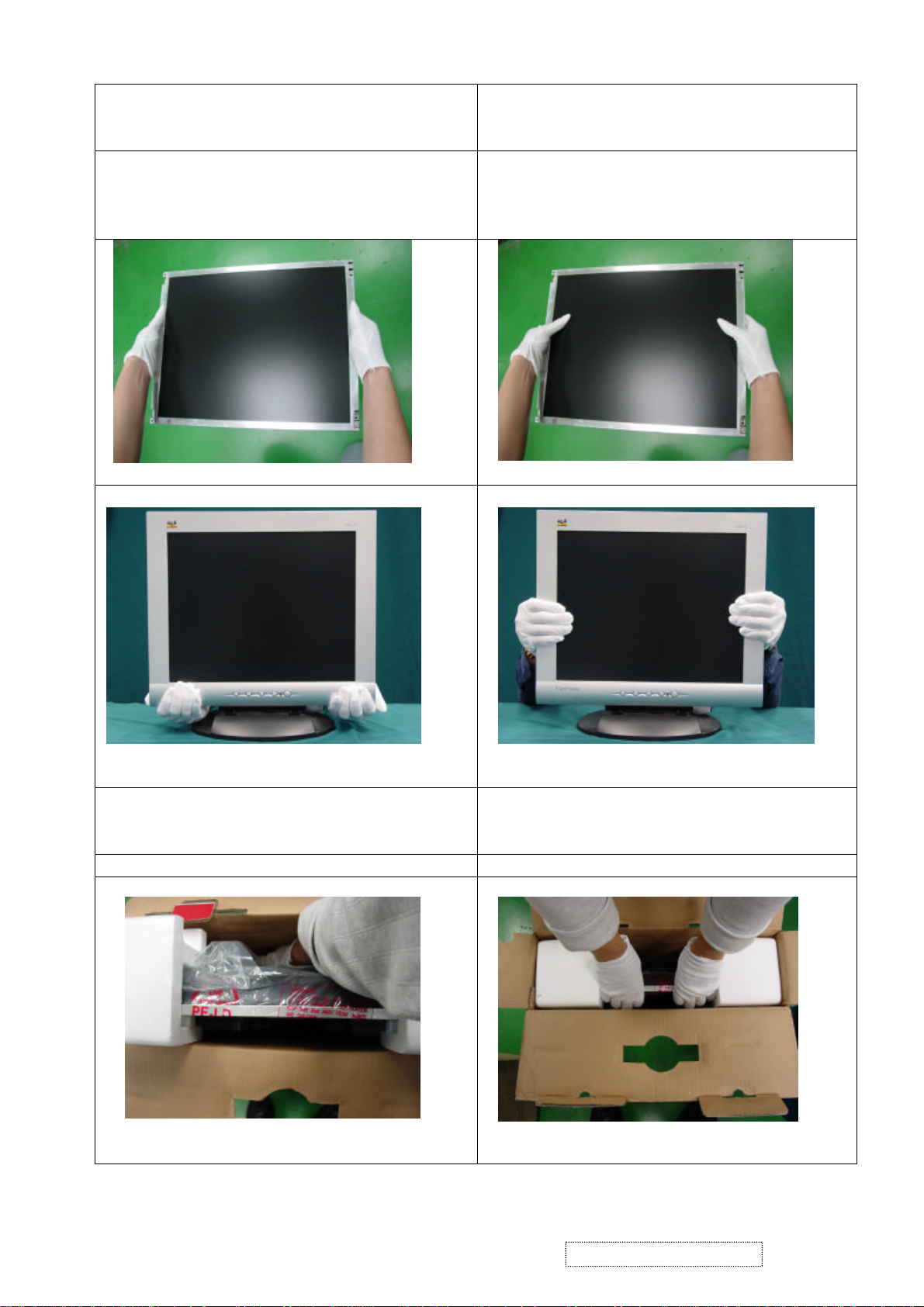
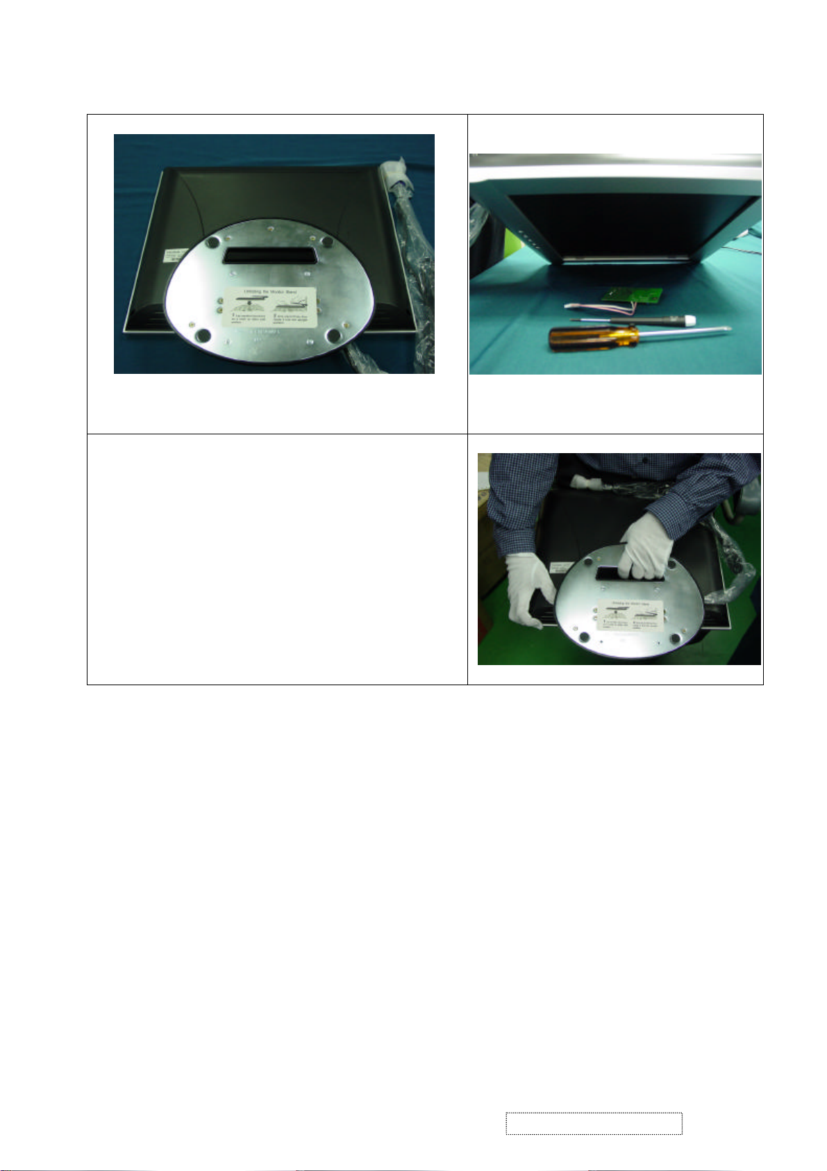
Surface of the LCD panel is pressed by fingers and
Correct Methods:
Only touch the metal frame of the LCD panel
or the front cover of the monitor.Do not
touch the surface of the polarizer.
Incorrect Methods:
that will probably cause “Mura”.
Take out the monitor with cushions Taking out the monitor by grasping the LCD
panel.That will probably cause “Mura”.
ViewSonic Corporation Confidential
-
3
Do Not Copy VE175-3
Page 7
ViewSonic Corporation Confidential
4
-
Do Not Copy VE175-3
Page 8

2. Specification
GENERAL specification
Test Resolution & Frequency 1280 x 1024 @ 60Hz
Test Image Size Full Size
Contrast and Brightness Controls
VIDEO INTERFACE
Analog Input Connector DB-15 (Analog), refer the appendix A
Video Cable Strain Relief
Video Cable Connector DB-15 Pin out Compliant DDC 1/2B
Video Signals Video RGB (Analog)
Video Impedance 75 Ohms (Analog), 100 Ohms (Digital)
Maximum PC Video Signal 950 mV with no damage to monitor
Maximum Mac Video Signal 1250 mV with no damage to monitor
Sync Signals TTL
DDC 1/2B Compliant with Revision 1.3
Sync Compatibility Separate Sync
Video Compatibility
Resolution Compatibility
Exclusions Not compatible with interlaced video
Factory Default:
Contrast = 50%, Brightness = 100%
Equal to twice the weight of the monitor for five
minutes
Shall be compatible with all PC type computers,
Macintosh computers, and after market video cards
640 x 350, 640 x 480, 720 x 400 (640 x 400), 800
x 600, 832 x 624, 1024 x 768, 1280 x 1024
TABLE : 15 PIN D-SUB CONNECTOR PIN ASSIGNMENT
This section describes the pin assignment of the LCD’s video connector. It is called 15 Pin Mini D-sub Connector.
Pin NO. Signal Connector
1 Red Video Signal
2 Green Video Signal
3 Blue Video Signal
4 N.C.
5 Ground
6 Ground
7 Ground
8 Ground
9 +5v
10 Ground
11 N.C.
12 DDC data
13 Horizontal sync signal
14 Vertical sync signal
15 DDC clock
ViewSonic Corporation Confidential
5
-
Do Not Copy VE175-3
Page 9
Power Supply
External Power Supply Part Number: HOAU222001
Input Voltage Range 90 to 264 VAC
Over Current Protection 5 A TYPICAL AT 5 VDC
Power Dissipation 45 Watts (typ)
Changing Modes
Maximum Mode Change Blank Time, for image
stability. Note:
1) Excluding “Auto Adjust” time
2) Under DOS mode (640 x 350, 720 x 400 & 640
3 seconds (Max)
1 seconds (Typ) for recognized timings
1-2 seconds (Typ) for unrecognized timing
.
x 400), there is no “Auto Adjust” feature.
3) The monitor needs to do “Auto Adjust” the first
time a new mode is detected.
Mode Change Image The image shall blank while the monitor changes
modes.
GTF
GTF N/A
Panel Characteristics
Panel Type AUO M170EG01 V.1
Type COLOR ACTIVE MATRIX TFT, TN TYPE
Active Size 337.92 (H) x 270.336 (V)
Pixel Arrangement RGB Vertical Stripe
Pixel Pitch 0.264 mm
Glass Treatment Anti Glare (Hard coating 2H)
# of Backlights 4 CCFL edge-light (2 top / 2 bottom)
Backlight Life 50,000 Hours (Typ) /30,000 Hours (Min)
Panel Performance
Luminance –
Condition:
CT = 6500K, Contrast = Max, Brightness = Max
xxx cd/m2 (max after 30 minute warmup)
260 cd/m2 (typ after 30 minute warmup)
210 cd/m2 (min after 30 minute warmup)
Brightness Uniformity 75% Entire Area (minimum)
Contrast Ratio xxx:1 (max), 450:1 (typ), 250:1 (min)
Color Depth 16.2 million colors (8 bit panel)
Viewing Angle (Horizontal) 140 deg @ CR>10,
Viewing Angle (Vertical) 130 deg @ CR>10,
Response Time
10%-90% @ Ta=25°C
16 ms (Tr= 12 ms, Tf = 4 ms) (typ)
25ms (max)
Panel Defects Please see Panel Quality Specifications.
ViewSonic Corporation Confidential
6
-
Do Not Copy VE175-3
Page 10
Horizontal/Vertical Frequency
Horizontal Frequency 30-82 kHz
Vertical Refresh Rate 50 – 75 Hz.
Maximum Pixel Clock 140 MHz
Sync Polarity Independent of sync polarity.
Primary Presets
Primary Preset 1280 x 1024 @ 60Hz
Look up table timing
<<Analog>>
1. 640 x 350 @ 70Hz, 31.5kHz
2. 640 x 400 @ 70Hz, 31.5kHz
3. 640 x 480 @ 60Hz, 31.5kHz
4. 640 x 480 @ 67Hz, 35.0kHz
5. 640 x 480 @ 75Hz, 37.5kHz
6. 640 x 480 @ 72Hz, 37.9kHz
7. 720 x 400 @ 70Hz, 31.5kHz
8. 800 x 600 @ 56Hz, 35.1kHz
9. 800 x 600 @ 60Hz, 37.9kHz
10. 800 x 600 @ 75Hz, 46.9kHz
11. 800 x 600 @ 72Hz, 48.1kHz
12. 832 x 624 @ 75Hz, 49.7kHz
13. 1024 x 768 @ 60Hz, 48.4kHz
14. 1024 x 768 @ 70Hz, 56.5kHz
15. 1024 x 768 @ 72Hz, 58.1kHz
16. 1024 x 768 @ 75Hz, 60.0kHz
17. 1280 x 1024 @ 60Hz, 63.4kHz
18. 1280 x 1024 @ 75Hz, 79.97kHz
User Presets
Number of User Presets (recognized timings)
Available
10 presets total in FIFO configuration.
Environmental Conditions
Operating Temperature 0°C to +40°C
Storage Temperature -20°C to +60°C
Operating Relative Humidity 20% to 90% RH Non-Condensing
Storage Relative Humidity 5% to 90% RH Non-Condensing
Operating Altitude 0 to +3,000 meters
Storage Altitude 0 to +12,000 meters
Dimensions (Base attached unless otherwise specified)
Width 414.5 mm
Height 403 mm
Depth 229 mm
Monitor Weight 5.7 kg /12.57lbs
Ergonomics
Tilt Up 20 degrees minimum
Tilt Down 5 degrees
ViewSonic Corporation Confidential
7
-
Do Not Copy VE175-3
Page 11
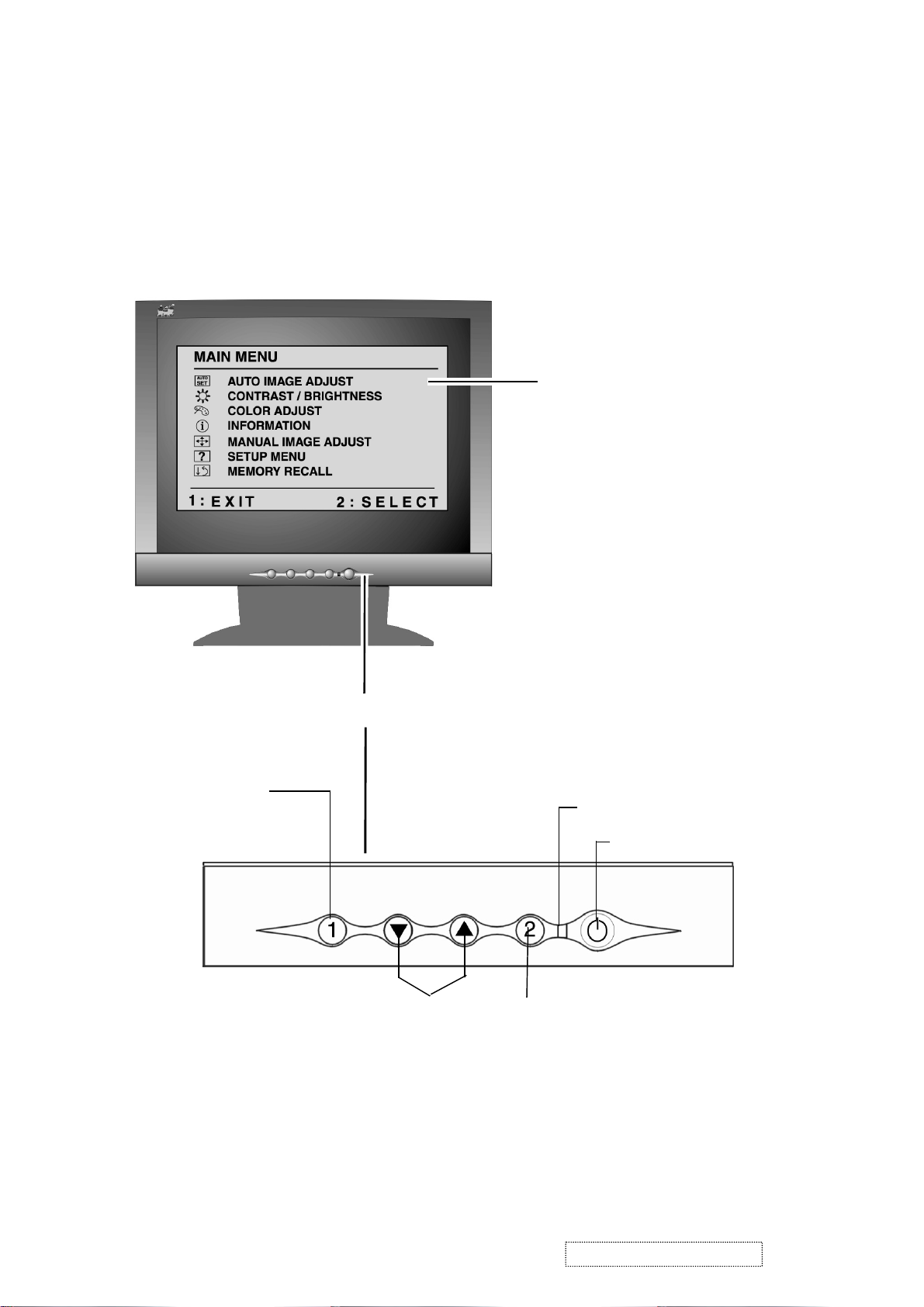
3. Front Panel Function Control Description
Adjusting the Screen Image
Use the buttons on the front control panel to display and adjust the OnView
®
controls which display on the screen. The OnView controls are explained at the
top of the next page.
Main Menu
with OnView controls
Displays, saves
changes to, and exits
the Main Menu.
Scroll through menu
options and adjust the
displayed control.
Front Control Panel
Power light
Power On/Off
Selects a highlighted control. Also,
displays the control screen for the
selected control and toggles
between control pairs.
ViewSonic Corporation Confidential
8
-
Do Not Copy VE175-3
Page 12
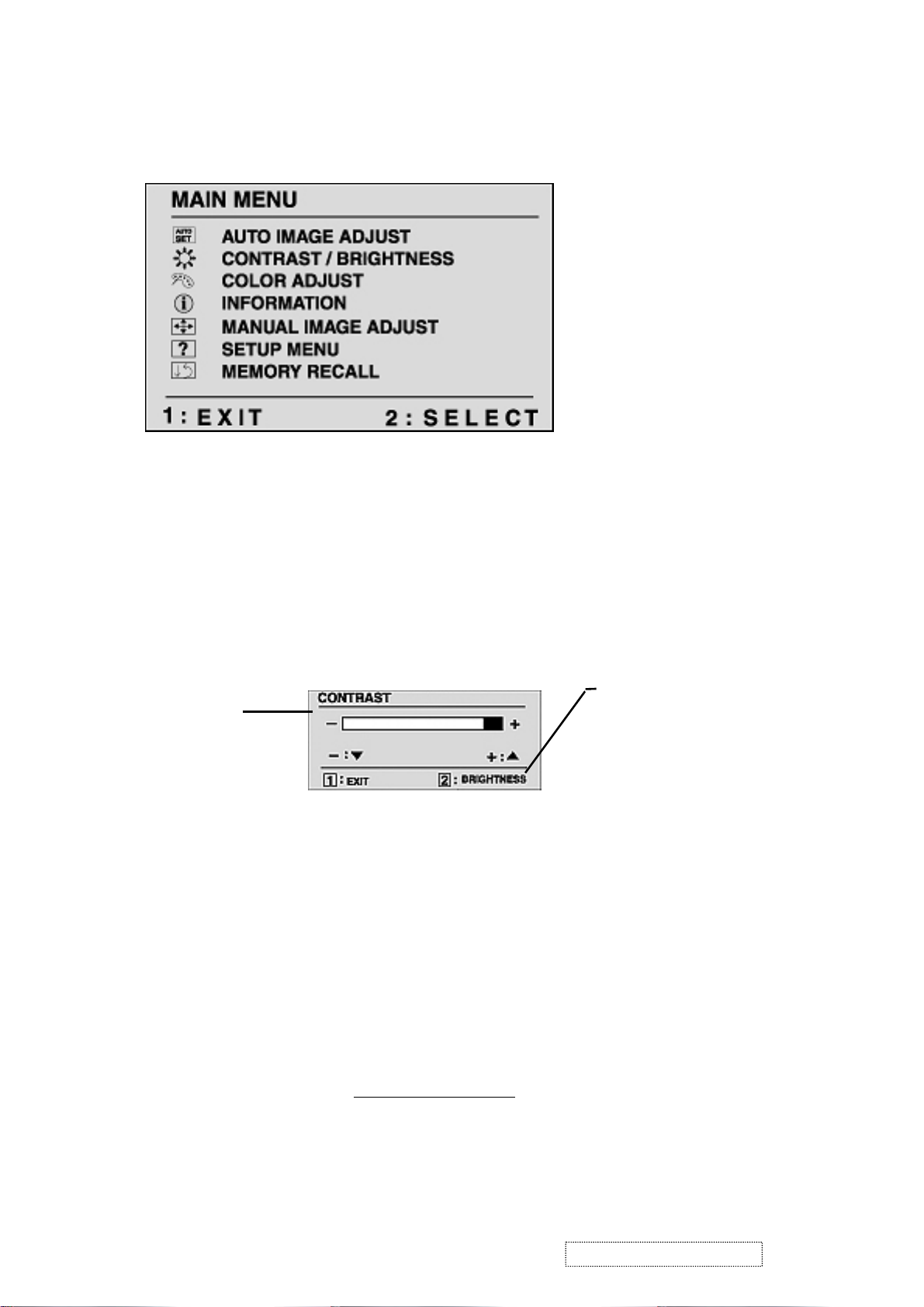
Do the following to adjust the screen image:
1
To display the Main Menu, press button [1].
NOTE: All OnView menus and adjustment screens disappear automatically
after about 30 seconds. This time period is adjustable through the Setup
menu and the OSD timeout control described on page 11.
2
To highlight a control you want to adjust, press I or J to scroll up or down
the Main Menu.
3
To select the highlighted control, press button [2]. A control screen appears
like the example shown below.
The line at the
TheJdown
arrow decreases,
I
up arrow
increases
4
To adjust the control, press the upIor downJbuttons.
5
To save the adjustments and exit the menu, press button [1] twice.
bottom of the screen
tells you what you
can do next - in this
example, either EXIT
or select the
BRIGHTNESS
control.
The following tips may help you optimize your display:
• Adjust your computer's graphic card so that it outputs a video signal 1280 x
1024 @ 60 Hz to the LCD dislay. (Look for instructions on “changing the
refresh rate” in your graphic card's user guide.)
• If necessary, make small adjustments using H. POSITION and V. POSITION
until the screen image is completely visible
. (The black border around the
edge of the screen should barely touch the illuminated “active area” of the
LCD dislay.)
ViewSonic Corporation Confidential
9
-
Do Not Copy VE175-3
Page 13

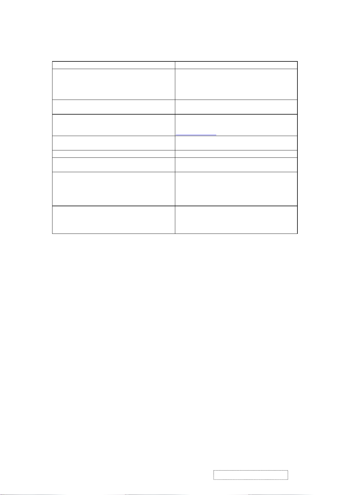
Main Menu Controls
Adjust the menu items shown below by using the up Iand down Jbuttons.
Control Explanation
Auto Adjust
automatically sizes, centers, and fine tunes the
video signal to eliminate waviness and distortion.
Press the [2] button to obtain a sharper image.
NOTE
: Auto Adjust works with most common video cards. If
this function does not work on your LCD dislay, then lower the
video refresh rate to 60 Hz and set the resolution to its pre-set
value.
Contrast
adjusts the difference between the image background
(black level) and the foreground (white level).
Brightness
Color Adjust
adjusts background black level of the screen image.
provides several color options: preset color
temperatures and User which allows you to adjust red (R), green
(G), and blue (B). The factory setting for this product is 6500K
(6500 Kelvin).
9300K
— Adds blue to the screen image for cooler white (used
in most office settings with fluorescent lighting).
6500K
— Adds red to the screen image for warmer white and
richer red. Default setting.
5400K — Adds green to the screen image for a darker color.
User
— Individual adjustments for red, green, and blue.
1
To select color (R, G or B) press button [2].
2
To adjust selected color, press I or J.
3
When you are finished making all color adjustments, press
button [1] twice.
ViewSonic Corporation Confidential
10
-
Do Not Copy VE175-3
Page 14

Control Explanation
i
Information
coming from the graphics card in your computer. See your
displays the timing mode (video signal input)
graphic card’s user guide for instructions on changing the
resolution and refresh rate (vertical frequency).
VESA 1280 x 1024 @ 60 Hz (recommended) means that the
resolution is 1280 x 1024 and the refresh rate is 60 Hertz.
Manual Image Adjust
The Manual Image Adjust controls are explained below:
H./V. Position
screen image. You can toggle between Horizontal and Vertical
by pressing button [2]. Horizontal moves the screen image to
the left or to the right. Vertical moves the screen image up and
down.
adjusts horizontal and vertical position of the
H. Size
NOTE:
Fine Tune sharpens focus by aligning the illuminated text and/
(Horizontal Size) adjusts the width of the screen image.
Vertical size is automatic with your LCD dislay.
or graphic characters.
NOTE: Try the Auto Adjust (see page 9) before using the Fine
Tune control.
Sharpness
adjusts the clarity and focus of the screen image.
ViewSonic Corporation Confidential
11
-
Do Not Copy VE175-3
Page 15
Control
Explanation
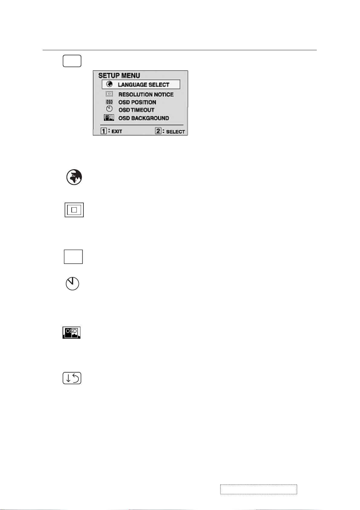
?
Setup Menu displays the menu shown below.
The Setup Menu controls are explained below.
L
anguage
Select allows you to choose the language used in
the menus and control screens.
Resolution Notice
advises the optimal resolution to use. After
selecting Resolution Notice, a sub menu appears asking if you
want to Disable or Enable the notice. If you want the Resolution
Notice to appear on-screen, select Enable.
OSD
OSD Position
allows you to move the on-screen display menus
and control screens.
OSD Timeout
sets the length of time an on-screen display
screen is displayed. For example, with a “15 second” setting, if
a control is not pushed within 15 seconds, the display screen
disappears.
OSD Background
allows you to turn the On-Screen display
background on or off. This means that while making adjustments
from the OSD control screens you can also view open software
applications, or the Windows desktop.
Memory Recall
returns adjustments to the original factory
settings if the display is operating in a factory Preset Timing
Mode listed in this user guide.
ViewSonic Corporation Confidential
12
-
Do Not Copy VE175-3
Page 16
Hot Key for Function Controls
is
connected) , then press
. After entering Burn in Mode. press
,
2] key at the same time and plug the
Buttons: Functions:
[Up] + [Down] arrows Recall Contrast or Brightness while in the
Contrast or Brightness adjustment.or recall both
of Contrast and Brightness when the OSD in not
on.
[1] + [2] Toggle 720x400 and 640x400 mode when input
720x400 or 640x400 mode.
[1] + [Up] + [Down] White Balance.White Balance should set the
screen on the pure black and white pattern with
640x480@60Hz
resolution.
[1] + [Down] (hold for 10 seconds) Power Lock (Unlock).User won’t be able to turn
off the monitor.
[1] +[Up] (hold for 10 seconds) OSD Lock (Unlock).
Then press [Up] key at the same time and plug the
AC cord.
un-plug the AC cord and be sure the signal cable
not connected (D-sub not
[2] key at the same time and plug the AC cord.
All Mode Reset. It will erase all end user’s setting
and restore the factory defaults.
Burn in Mode
[1] button. you can find the information about this
monitor.
un-plug the AC cord and be sure the signal cable
then press [
AC cord.
Factory in Mode.
ViewSonic Corporation Confidential
13
-
Do Not Copy VE175-3
Page 17

4. Circuit Description
1. WORKING THEOREM
A. DC-DC CONVERTER
This brick converts the 5V input voltage to 3.3V and 1.8V for controller use.
It consists of a Liner Regulator IC (AIC117), filter capacitor, and constant voltage capacitor. The AIC1117 is
a low dropout three terminal regulator with 800mA output current capability. Its low dropout voltage and fast
transient response make it ideal for low voltage microprocessor applications. Internal current and thermal limiting
provides protection against any overload condition that would create excessive junction temperatures.
B. A/D converter
The gmZAN3SL provides all the key display functions required for displaying a good quality image on a LCD
panel when connected to the PC source with analog interface. The integrated functions include a high-speed triple-ADC
and PLL, a high quality zoom and shrink scaling engine, an on-screen display (OSD) controller, digital color controls
and LVDS Transmitters. Its provides a front-end analog interface with standard VGA compliance and an output industry
standard LVDS interface for speed grade up to XGA and SXGA respectively. Typical gmZAN3SL based design need an
external 8051 equivalent MCU with integrated flash. It provides the flexibility of choosing either 8bit parallel or 6wire
host interface. Integrated LVDS transmitters and PWM based backlight control circuitry provides direct interconnect to
LCD panels and backlight inverters. Integrated Schmitt circuit, integrated reset circuit and single crystal base makes
gmZAN3XL/SL an ideal choice for the entry- level SXGA monitor design.
D. MCU:
The MTV312M micro-controller is an 8051 CPU core embedded device especially tailored for CRT/LCD Monitor
applications. It includes an 8051 CPU core, 1024-byte SRAM, 14 built-in PWM DACs, VESA DDC interface,
4- channel A/D converter, and a 64K-byte internal program Flash-ROM.
ViewSonic Corporation Confidential
14
-
Do Not Copy VE175-3
Page 18

5. Adjusting Procedure
5-1 Product
17” LCD Monitor
5-2 Test Equipment
Color Video Signal & Pattern (or PC with SXGA resolution)
5-3 Test Condition
Before function test and alignment, each LCD Monitor should be run-in and warmed up for at least
30 minutes with the following conditions:
(a) In room temperature,
(b) With full-white screen, RGB, and Black
(c) With cycled display modes,
640x480 (H=43.27 kHz, V=85Hz)
800x600 (H=53.7 kHz, V=85Hz)
1024x768 (H=68.67 kHz, V=85Hz)
1280x1024 (H=79.97 kHz, V=75Hz)
5-4 Test Display Modes & Pattern
5-4.1 Compatible Modes
Analog Digital
1. 640 x 350 @ 70Hz, 31.5kHz
2. 640 x 480 @ 60Hz, 31.5kHz
3. 640 x 480 @ 67Hz, 35.0kHz
4. 640 x 480 @ 75Hz, 37.5kHz
5. 640 x 480 @ 72Hz, 37.9kHz
6. 720 x 400 @ 70Hz, 31.5kHz
7. 800 x 600 @ 56Hz, 35.1kHz
8. 800 x 600 @ 60Hz, 37.9kHz
09. 800 x 600 @ 75Hz, 46.9kHz
10. 800 x 600 @ 72Hz, 48.1kHz
11. 832 x 624 @ 75Hz, 49.7kHz
12. 1024 x 768 @ 60Hz, 48.4kHz
13. 1024 x 768 @ 70Hz, 56.5kHz
14. 1024 x 768 @ 72Hz, 58.1kHz
15. 1024 x 768 @ 75Hz, 60.0kHz
16. 1024 x 768 @ 85Hz, 68.67kHz
17. 1280 x 1024 @ 60Hz, 63.4kHz
18. 1280 x 1024 @ 75Hz, 79.97kHz
5-4.2 Auto Image Adjust
Please select and enter “Auto Image Adjust” function on Main Menu to see if it is workable. The
“Auto Image Adjust” function is aimed to offer a better screen quality by built-in ASIC. For
optimum screen quality, the user has to adjust each function manually.
5-4.3 Firmware
Test Pattern: Burn in Mode (Refer to Chapter III-3. Hot Keys for Function Controls)
- Make sure the F/W is the latest version.
5-4.4 DDC
5-4.5 Fine Tune and Sharpness
Test Pattern: EDID program
- Make sure it can pass test program.
Test Signal: 1280x1024@60Hz
Test Pattern: Line Moiré Pattern
- Check and see if the image has noise and focus performs well. Eliminate visual line bar.
- If not, readjust by the following steps:
(a) Select and enter “Fine Tune” function on “Manual Image Adjust” to adjust the image to
eliminate visual wavy noise.
(b) Then, select and enter “Sharpness” function to adjust the clarity and focus of the screen image.
ViewSonic Corporation Confidential
15
-
Do Not Copy VE175-3
Page 19

5-4.6 White Balance
Test Signal: 640x480@60Hz
Test Pattern: Full White and Black Pattern
5-4.7 R, G, B, Colors Contrast
Test Signal: 1280x1024@60Hz
Test Pattern: R, G, B, Color Intensities Pattern and 16 Gray Scale Pattern
5-4.8 Dead Pixel and Line
Test Signal: 1280x1024@60Hz
Test Pattern: Dark and White Screen Pattern
- Check and see if there are dead pixels on LCD panel with shadow gauge and filter film.
- The total numbers and distance of dead pixels should be compliant with the spec.
5-4.9 Mura
Test Pattern: White, RGB, Black, & Grey
Test Tool: 10 % ND Filter
- Check if the Mura can pass 10 % ND Filter.
5-4.10 Check for Secondary Display Modes
Test Signal:
Analog: 640x350@70Hz; 640x480@60/67/72/75/85Hz;
720x400@70Hz; 800x600@56/60/72/75/85Hz;
832x624@75Hz, 1024x768@60/70/72/75/85Hz;
1280x1024@60/75Hz
Digital: 640x350@70Hz; 640x480@60/72/75/85Hz;
720x400@70Hz; 800x600@56/60/72/75/85Hz;
1024x768@60/70/72/75/85Hz; 1152x870@75Hz,
1280x720@60Hz, 1280x1024@60Hz
- Normally when the primary mode 1280*1024@60Hz is well adjusted and compliant with the
specification, the secondary display modes will be great possible to be compliant with the spec. But
we still have to check with the general test pattern to make sure every secondary is compliant with the
specification.
5-4.11 All Modes Reset
After final QC step, we have to erase all saved changes again and restore the factory defaults. You
should do “All Mode Reset” again.
1.5.13 Power off Monitor
Turn off the monitor by pressing “Power” button.
ViewSonic Corporation Confidential
16
-
Do Not Copy VE175-3
Page 20

15pin VGA
connector
5-5. Firmware Upgrade Procedure
Equipment Needed
- VE175 Monitor
- Fixture for Firmware Upgrade
- Power Adapter (P/N: 47.58201.001) x1 for Fixture
- VGA Cable (P/N: 42.59901.003) x1(Pin 4, 11 should be connected to GND)
- PC (Personal Computer)
- LPT Cable (P/N: 42.59906.001) x1
- Firmware Upgrade Program
- One additional monitor for checking the program execution
PC
Fixture
Printer Port
VE175
5-6 EDID Procedure
DDC User’s manual
1. Hardware installation
A. The EDID cable has equipped 2 different terminals;
one is male 25 pin printer connector and another side is male 15 pin D-sub connecter.
B. Connect the EDID cable from PC Printer port to monitor D-sub connector.
C. Make sure the monitor was working under power saving mode and keep it at “Power Saving state” during
DDC process.
ViewSonic Corporation Confidential
PC printer
port 25pin
EDID-Kit
Cable
17
D-Sub of
Monitor
-
Do Not Copy VE175-3
Page 21

2. Programming procedure
A. Normally, you received a EDID zip file of new model. You need to unzipped it.
B. There will need the following files for DDC program: (VE175 is an example)
1. DPS.EXE
2. VE175.BAT
3. VE175.DDC
4. VE175.CFG
5. VE175.DPS
C.Execute the VE175.BAT (for VE175 monitor only) from Programming PC. Below screen will display.
Fig-DDC1
Refer to Fig-DDC1; you have to select the required item if the display data was not you want.
Press 1:
For year, the cursor will move to the column behind “Edit Year” than you can key in the data you want after
that press enter to exit and return. (It needs 4 numbers for this data)
Press 2:
For week, the cursor will move to the column behind “Edit Week” than you can key in the data you want
after that press enter to exit and return. (This data is within 1 ~ 53.)
Press 3:
For S/N,, the cursor will move to the column behind “Edit S/N” than you can key in the data you want after that
press enter to exit and return. (This data is within 0 ~ 99999, 5 numbers max.)
D. Press “ESC” or “Enter” key to return main menu, the Fig-DDC2 will be displayed and the correct serial number
will show on right corner of screen.
ViewSonic Corporation Confidential
18
-
Do Not Copy VE175-3
Page 22

Fig-DDC2
Under Fig-DDC2, you could change the “Week” data by press “*” key and the “S/N” data by press “-“ key.
Press 3 “DDC Writer/Check Data”:
display on the screen after programming.
Please refer to Fig-DDC3 below, the DDC process is finished.
The Kit will start to program new data of EDID into monitor, all DDC data will
Display updated serial
number.
ViewSonic Corporation Confidential
Fig-DDC3
19
-
Do Not Copy VE175-3
Page 23

The message (E2PROM Acknowledge Not Echo) will display on the screen if there is any error detected by Programming
PC. If error message is happened, please re-check the connection of cable and return to first step.
Please refer to the Viewsonic EDID data format that was printing on ID label.
PPPYYWWxxxxx
PPP = Viewsonic Regional Product ID Code, EX. VE500 is “910”, VE700 is “A10” and VG900 is “A1C ”,
VE175-3 is “P8D” .
YY= 2 digits of Manufacturing year. (range 1996-2015).
WW = 2 digits of Manufacturing week (range 01-54).
xxxxx = 5 digits of Sequence number. (range 00001-99999).
5-7 . ISP procedure
Connection of ISP Kit:
Using Printer cable connect ISP-board (P1) with PC Printer port.
Using VGA cable connect ISP-board (CN702) with monitor (destination).
ViewSonic Corporation Confidential
20
-
Do Not Copy VE175-3
Page 24

From Pc Signal
To Monitor
Insert4,8 ON(VE1753)
(1,2,3,4,5,6,7, OFF)
12345678
Printer cable
ViewSonic Corporation Confidential
21
-
Do Not Copy VE175-3
Page 25

Monitor ISP Mode setting
In the power off mode,Pressq, p, 2 keys button together keep pressing the 2 key and press then power key
To wake up system. from adapter.
An OSD message “ ISP Mode” will display on monitor screen.
PC portion:
1. We need 2 files for ISP windows version :
2. For Win2K and WinXP, Setup the Port95nt.exe program firstly. When the setup is completed, the PC need to
Port95nt.exe and SAMPOISP_2.5a.zip . We can save them in t
the same folder.
restart.(For Win98, this procedure is not necessary)
ViewSonic Corporation Confidential
22
-
Do Not Copy VE175-3
Page 26

3. Unzip SAMPOISP_2.5a.zip file in the same folder and Install the Setup.exe.
4. When the setup is completed, launch the Sampotech ISP program.
ViewSonic Corporation Confidential
23
-
Do Not Copy VE175-3
Page 27

5. When the program is ready, we have the screen as the following picture.
6. In the program picture, we need to setup 3 items.
a. Click “Creat Security File” button, we have to setup 3 addresses:
ISP Slave Add. “7C”
Slave Add. “7C”
Command 1 “77”
After setting ok, click OK to exit the Security menu.
ViewSonic Corporation Confidential
24
-
Do Not Copy VE175-3
Page 28

b. Choose the MTV type to MTV312M64.
ViewSonic Corporation Confidential
25
-
Do Not Copy VE175-3
Page 29

c. Click “Load MCU File”
button and choose the file you want to update.
7. Click RUN button to start ISP. If the entrance procedure of ISP is correct, there will be a message box as the
following picture. Click OK to program the MCU.
ViewSonic Corporation Confidential
26
-
Do Not Copy VE175-3
Page 30

8. If every setting is ok, the programming procedure is as the following picture.
9. If the
programming process is correct, the monitor will turn off and then turn on. Click Ok to exit the ISP mode.
So far, we have finished the ISP programming process.
ViewSonic Corporation Confidential
27
-
Do Not Copy VE175-3
Page 31

6. Trouble Shooting Flow Chart
ViewSonic Corporation Confidential
28
-
Do Not Copy VE175-3
Page 32

ViewSonic Corporation Confidential
29
-
Do Not Copy VE175-3
Page 33

G
p
Power 5V-In J P1
5V-in
LVDS Signal Output
anel
To
CN4
LVDS Signa
I/F bard power
Check Start
Check
+3.3V_VDD(U6)
+1.8V_VDD(U7)
MCU3V3
Power _In
ZAN3SL & MCU
Check Start
(no display)
No
Yes
l
Check U2
Output LVDS Signal
(CN4 Odd and
Even Data
No
Yes
)
End
Power Part
No
Check 5V input
(JP2,pin1,pin2)
Yes
End
Yes
Zan3&Mcu
Clock(X1_12MHz)、Rest time
Iinput Signal(R、G、B、H/V_Sync)
R
VGA Signal Input
CN1
Check:
I2C Signal(include U2&U4、
Host Interface (AD0~AD&)、
U2&U4 Power
B
I/F Board QPWB-5642T8
ViewSonic Corporation Confidential
30
-
Do Not Copy VE175-3
Page 34

OSD no respones
downer side
Check SW
board
S1~S5
Check I/F board
& panel
Too dim
The brightness is
different between
upper Side and
Partly picture
without Color
Vertical,
Horizontal None
synchronousness
A few of colorfully
Vertical lines
RGB Signal error
H/Vsync error
Check OSD
adjustment
Check inverter
&backlight
Check I/F
board
Check panel
Check SW board
JP1 & Inverter
&I/F board
Even(or odd)
vertical Line is dark
ViewSonic Corporation Confidential
31
-
Do Not Copy VE175-3
Page 35

F1
M-MS-0808-9180
SSAKH1356D8-T--
1
7. Recommended Spare Parts List
RECOMMENDED SPARE PARTS LIST (VE175-3)
ViewSonic Model Number: VS10231
Rev: 1a
Item ECR/ECN ViewSonic P/N Ref. P/N Location Universal number# Q'ty
Accessories
1
PC Board Assembly:
2 I/F BOARD B-00001028 DPWBN5642T8---- 1
3 INVERTER+POWER B-00001029 RUNTP5624T8---- 1
4 SW BOARD B-00001030 DPWBN5614T8---- 1
Cabinets:
5 BACK BEZEL C-00001031 GCABB1734D8F--F 1
6 FRONT BEZEL C-00001032 GCABA2301D8F--E 1
7 HINGE COVER C-00001045 GCOVD2533D8F--D 1
Cables:
8 LVDS CABLE CB-00001033 QCODS1752T8---- 1
9 VGA CABLE 1.8M CB-00001034 QCODS1741T8---- 1
Documentation:
10 CD DRIVER DC-00001035 DDSKC0050T8---- 1
11 ID label DC-00001036 TLAB-5643T8---- 1
Electronic
12 PANEL(17" AU) E-00001037 VVLM170EG01---- 1
Components:
13 44 PIN IC SOCKET M-MS-0808-8003 QSOCI1642T844-- U4 1
14 CPU (MYSON MTV312MV64)) E-00001038 VSIMTV312M----- U4 1
15 CRYSTAL 12MHZ E-X-0415-0127 RCRSL1167T8---- X1 1
16 EEPROM E-00001039 VSIMP24LC16B--A U3 1
17 FOUSE 4A E-FS-0410-0099 QFS-Z402F-81UAA
18 SCALLER GENESIS gmZAN3 E-00001040 VSIGMZAN3SL---A U2 1
Hardware:
19 AC INLET BRACKET HW-00001041 LANGF2157D8---- 1
20 HINGE M-MS-0808-8124 MHNGM0019D8---- 1
21 MAIN BRACKET HW-00001042 LANGF2086D8---K 1
22 SCREW (To assembly the cabinet) M-SCW-0824-6734 XEPSB40P12000-- 2
Miscellaneous:
23
Packing Material:
24 CARTON P-00001043 SPAKC3412D8---D 1
25
26 POLYFOAM P-FM-0602-0798 SPAKA6503D8F--- 1
Plastics:
27 BASE (Pedestal) PL-PS-0715-0989 GSTN-2870D8F--A 1
28 BASE PLATE M-MS-0808-8901 LANGF2052D8---A 1
29 DECORATION PLATE PL-00001044 PISLV0248D8---B 1
30 HINGE COVER C-00001045 GCOVD2533D8F--D 1
31 SWITCH KNOB PL-NB-0707-0214 JKNBP2309D8F--A 1
32 VIEWSONIC LOGO PLATE M-CV-0830-2476 GCOVD2390D8F--- 1
Description
AC POWER CORD 1.8M A-PC-0106-0180 QACC-1126D8D--- 1
VIEWSONIC LOGO M-MS-0808-6478 HBDGA1724D8---- 1
PE BAG
1
ViewSonic Corporation Confidential
-
Do Not Copy VE175-3
32
Page 36

FOR INVERTER*4,I/F *3,SHIELD CASE*2,AC
FOR INVERTER*4,I/F *3,SHIELD CASE*2,AC
BOM LIST (VE175-3)
ViewSonic Model Number: VS10231
Rev: 1a
Item ViewSonic P/N Ref.P/N Description Location Q'ty
1 PL-PS-0715-0989 GSTN-2870D8F--A BASE BASE 1PCS
2 M-MS-0808-8124 MHNGM0019D8---- HINGE HINGE 1PCS
3 M-MS-0808-8901 LANGF2052D8---A BASE PLATE BASE PLATE 1PCS
4 M-SCW-0824-6737 XESSD30P06000-- BASE PLATE/BASE*5 BASE PLATE/BASE*5 5PCS
5 M-SCW-0824-6736 XBSSD40P12000-- BASE PLATE/HINGE*4, BASE PLATE/HINGE*4, 4PCS
6 PL-00001047 GLEGG1460D8F--B RUBBER LEG RUBBER LEG 1PCS
7 #N/A QCNWS0908T8020- POWER WIRE POWER WIRE 1PCS
8 #N/A TLABZ4916T8---- INVERTER LABEL INVERTER LABEL 1PCS
9 C-00001032 GCABA2301D8F--E CAB-A CAB-A 1PCS
10 C-00001031 GCABB1734D8F--F CAB-B CAB-B 1PCS
11 PL-NB-0707-0214 JKNBP2309D8F--A KNOB KNOB 1PCS
12 M-CV-0830-2476 GCOVD2390D8F--- LOGO PLATE LOGO PLATE 1PCS
13 C-00001045 GCOVD2533D8F--D HINGE COVER HINGE COVER 1PCS
14 HW-00001041 LANGF2157D8---- AC INLET BRACKET AC INLET BRACKET 1PCS
15 HW-00001046 PSLDM6594D8---- SHIELD CASE SHIELD CASE 1PCS
FOR MAIN BRACKET ( SCREW, BRAZIER
16 M-SCW-0824-6804 XEASD30P06000-17 M-SCW-0824-6738 XEPSN26P06000-- KEY BOARD/CAB-A*3 KEY BOARD/CAB-A*3 3PCS
18 #N/A XEPSN40P12000-- FOR CAB-A/B FOR CAB-A/B 2PCS
19 M-SCW-0824-6740 XBMSD30P04000-20 M-SCW-0824-6812 XEASD30P12TV0-- HINGE*2 HINGE*2 2PCS
21 M-SCW-0824-6739 XBMSD40P08TV0-- MHNGM0019*4 MHNGM0019*4 4PCS
22 HW-00001048 XBMSD40P06000-- AC BRACKET & MAIN BRACKET AC BRACKET & MAIN BRACKET 1PCS
23 M-MS-0808-9174 HDECP1929D8F--- LENS LENS 1PCS
24 M-MS-0808-6478 HBDGA1724D8---- VS LOGO VS LOGO 1PCS
25 HW-00001050 XHISE40P08TV0-- GROUND GROUND 1PCS
26 PL-00001044 PISLV0248D8---B DECORATION PLATE DECORATION PLATE 1PCS
27 M-BK-0805-0057 LANGF2063D8---- KENSINGTON BRACKET KENSINGTON BRACKET 1PCS
28 #N/A ZTAPEN018D030U- TYPE 0.05M*3,0.1*1 TYPE 0.05M*3,0.1*1 0.15M
29 #N/A PISLS1182D8---- PC PLATE PC PLATE 2PCS
30 #N/A XBJSD30P04000-- FOR GROUND FOR GROUND 1PCS
31 #N/A XBSSN30P06000-- AC SOCKET&LANGF2157*2 AC SOCKET&LANGF2157*2 2PCS
32 B-00001029 RUNTP5624T8D--- INVERTER+POWER (JHC BLACK) INVERTER+POWER (JHC BLACK) 1PCS
33 DC-00001036 TLAB-5643T8---- MODEL LABEL MODEL LABEL 1PCS
34 CB-00001034 QCODS1741T8---- VGA CABLE 1.8M FOR PC99(BLACK) VGA CABLE 1.8M FOR PC99(BLACK) 1PCS
35 A-PC-0106-0180 QACC-1126D8D--- AC POWER CORD (1.8M) USA(BLACK) AC POWER CORD (1.8M) USA(BLACK) 1PCS
36 M-LB-0813-0527 TLABZ3903D8---- UPC LABEL UPC LABEL 1PCS
37 #N/A TLAB-5523D8---- S/N LABEL S/N LABEL 1PCS
38 #N/A TINSE3132T8---- USER'S MANUAL USER'S MANUAL 1PCS
39 #N/A TLAB-5430T8---- STAND LABEL STAND LABEL 1PCS
40 P-FM-0602-0798 SPAKA6503D8F--- EPS PAD EPS PAD 1PCS
41 P-00001043 SPAKC3412D8---D CARTON CARTON 1PCS
42 M-MS-0808-9180 SSAKH1356D8-T-- SET BAG SET BAG 1PCS
43 #N/A SPAKW1155D8---C PALLET (981x1143) PALLET (981x1143) 0.0179PCS
44 #N/A SPAKK6273D8---C CORNER PAPER (50x50x2000)V CORNER PAPER (50x50x2000)V 0.0714PCS
45 #N/A SPAKK6322D8---A CORNER PAPER (50x50x1000)T CORNER PAPER (50x50x1000)T 0.0357PCS
46 #N/A ZTAPEQ019T040-- TAPE 50MM*1 TAPE 50MM*1 0.05M
47 #N/A ZTAPEQ072T050-B TAPE 800MM*3,500MM*2 TAPE 800MM*3,500MM*2 3.4M
48 #N/A SPAKK6346D8---- CORRUGATED BOARD (980x1140)TB CORRUGATED BOARD (980x1140)TB 0.0400PCS
49 #N/A SPAKK6357D8---A CORNER PAPER (50x50x2200)V CORNER PAPER (50x50x2200)V 0.070PCS
50 #N/A SPAKK1703T8Z--B CORNER PAPER (50x50x120)T CORNER PAPER (50x50x120)T 0.0714PCS
51 #N/A PISL-1246D8---A PROTECT SHEET WITH PRINTING PROTECT SHEET WITH PRINTING 1PCS
52 #N/A ZTAPEQ050Y062-- SECURITY TAPE SECURITY TAPE 0.5300 PCS
53 #N/A TLAB-5439T8---- 3 WORD LABEL 3 WORD LABEL 1PCS
HEAD-3*6-Bronze)"
BRACKET*1
FOR MAIN BRACKET 11PCS
BRACKET*1
10PCS
MODEL: DPWBN5642T8----(FOR MAIN BOARD)
Item ViewSonic P/N Ref.P/N Description Location Q'ty
1 #N/A QPWB-5642T8---- I/F Board I/F Board 1PCS
2 #N/A VRMDNVG--000J-A Resistor,SMT,0603,0O,±5%,1/16W R53, D5, R62, R63, R90, R92 6PCS
3 #N/A VRMDNVG--101J-A Resistor,SMT,0603,100O,±5%,1/16W
4 #N/A VRMDNVG--102J-A Resistor,SMT,0603,1KO,±5%,1/16W R50, R67 ,R72 ,R73, R74, R96 6PCS
5 #N/A VRMDNVG--103J-A Resistor,SMT,0603,10KO,±5%,1/16W
6 #N/A VRMDNVG--105J-A Resistor,SMT,0603,1MO,±5%,1/16W R54 1PCS
7 #N/A VRMDNVG--202J-A Resistor,SMT,0603,2KO,±5%,1/16W R52, R68 2PCS
8 #N/A VRMDNVG--200J-A Resistor,SMT,0603,20O,±5%,1/16W R18, R19 2PCS
9 #N/A VRMDNVG--331J-A ResistorSMT,0603,330O,±5%,1/16W R84, R85 2PCS
10 #N/A VRMDNVG--203J-A ResistorSMT,0603,20KO,±5%,1/16W R95 1PCS
#N/A R43, R55, R56, R57, R64, R65, R81, R83, R86
ViewSonic Corporation Confidential
33
R23, R28, R29, R30, R31, R35, R36, R37, R38
,R41
R1, R2, R26, R27, R33, R39 ,R40 ,R48, R49,R60,
R61, R69, R70
-
Do Not Copy VE175-3
19PCS
13PCS
Page 37

Item ViewSonic P/N Ref.P/N Description Location Q'ty
11 #N/A VRMDNVG--472J-A Resistor,SMT,0603,4.7KO,±5%,1/16W R24, R25, R71, R78 ,R79 ,R80, R82 7PCS
12 #N/A VRMDNVG--104J-A Resistor,SMT,0603,100KO,±5%,1/16W R3 1PCS
13 #N/A VRMDNVG--473J-A Resistor,SMT,0603,47KO,±5%,1/16W R66 1PCS
14 #N/A VRMDNVG--750J-A Resistor,SMT,0603,75O,±5%,1/16W R10, R11, R12, R22 4PCS
15 #N/A VRMDNVG-1000F-A Resistor,SMT,0603,100O,±1%,1/16W R6, R7, R8 3PCS
16 #N/A VRMDNVG-1200F-A Resistor,SMT,0603,120O,±1%,1/16W R13, R14, R15 3PCS
17 #N/A RNWRB1618T8101M Resistor array,SMT,8P4R,25V,100O RN1, RN2 2PCS
18 #N/A RNWRB1618T8472A Resistor array,SMT,8P4R,25V,4.7KO RN3 1PCS
19 #N/A VCICHN1HH101J-A Capacitor,SMT,0603,50V,100P C21, C22 2PCS
20 #N/A VCICHN1HH220J-A Capacitor,SMT,0603,50V,22P C57, C58 2PCS
21 #N/A VCIRHN1HG103K-A Capacitor,SMT,0603,50V,0.01U C11, C15, C16,C3 ,C4 ,C5 ,C50 ,C6 ,C7 ,C8, C9 11PCS
22 #N/A VCLFHN1CG105Z-A Capacitor,SMT,0805,50V,1U C63 ,R93, R94 3PCS
23 #N/A VCLFHN1HG104Z-A Capacitor,SMT,0603,50V,0.1U
#N/A
#N/A
24 E-C-0404-4947 VCICHN1HH330J-A Capacitor,SMT,0603,50V,33P R34 1PCS
25 E-D-0403-0531 VSD1N4148-----A DIODE,IN1418 D1 D2 2PCS
26 E-D-0403-0657 VSZRLZ5.6B----A ZENER DIODE,5.6V D3 D4 D6 D8 D9 5PCS
27 #N/A VSDBAV99------A DIODE,BAV99(75V/4NS/250mW) D10 D11 D7 3PCS
28 #N/A VSDDL4001-----A DIODE,DL4001 D13 1PCS
29 #N/A RFIL-5187T8500A BEAD,100MHZ/50O,±25%,PBY32161 D14.(1206), 1PCS
30 E-L-0407-1559 RFIL-5232T8300A BEAD,100MHZ/30O,±25%,NBQ16080 FB5 FB6 FB7 FB8 FB9.(0603), 5PCS
31 #N/A RFIL-5240T8110A BEAD,100MHZ/11O,±25%,SBY20120 FB4 L1 L2 L3 L4 L5 L6.(0805), 7PCS
32 #N/A RFIL-5235T8900A BEAD,100MHZ/90O,±25%,NBQ16080 FB1 FB2 FB3 3PCS
33 #N/A VST2N3904-----A Transistor,2N3904,(NPN T.R VCEO=40VAC) Q3 Q4 Q5 Q6 4PCS
34 #N/A VSTMMBT3904T-MA Transistor,MMBT3904T,(NPN T.R VCEO=40VAC) Q3 Q4 Q5 Q6 4PCS
35 #N/A VST2N3906-----A Transistor,2N3906,(PNP T.R VCEO=40VAC) Q1 Q2 Q7 Q8 4PCS
36 E-FS-0410-0099 QFS-Z402F-81UAA FUSE, 4A/125V F1.(4A/125V), 1PCS
37 E-00001040 VSIGMZAN3SL---A GENESIS SCALER ,gmZAN3SL U2 1PCS
38 E-00001039 VSIMP24LC16B--A EEPROM,IC 24C16B U3 1PCS
39 #N/A VSISDM9435A---A Power PMOSFET IC SDM9435A U5 1PCS
40 E-IC-0401-2120 VSIAIC1117-33-A Power Regulator 3.3V IC AIC1117-33(SOD223) U6 1PCS
41 #N/A VSIAIC1117-18-A Power Regulator 1.8V IC AIC1117-18(SOD223) U7 1PCS
42 M-MS-0808-8003 QSOCI1642T844-- IC SOCKET 44 PIN U4 1PCS
43 #N/A VCEATU1CH106M5- E,Capacitor,(10UF/16V) C1 C24 C31 C38 C41 5PCS
44 #N/A VCEATU1CH107M5- E,Capacitor,(100UF/16V) C61 C70 C73 C74 C77. 5PCS
45 #N/A VCEATU1CH226M5- E,Capacitor,(22UF/16V) C59 1PCS
46 E-00001038 VSIMTV312M----- MYSON MTV312MV64 U4 1PCS
47 E-IC-0401-2922 VSIMTV312M64--S SECOND SOURCE U4 1PCS
48 #N/A TLAB-4862D8---- BIOS LABEL BIOS LABEL 1PCS
49 #N/A VCNCP663USJ---- HEADER 15*2 CN4. 1PCS
50 #N/A VCNCP090DSEJST- Connector 13PIN J1 1PCS
51 #N/A VCNCP0908SEJST- Connector 8PIN JP1 1PCS
52 #N/A VCNCP0906SEJST- Connector 6PIN JP3 1PCS
53 E-X-0415-0127 RCRSL1167T8---- OSC(12 MHZ) X1. 1PCS
54 #N/A RCRSL1217T8---- OSC(12 MHZ) X1. 1PCS
55 #N/A RCRSL1215T8---- OSC(12 MHZ) X1. 1PCS
56 B-SB-0221-0505 TLAB-3547T8---- PCB LABEL PCB LABEL 1PCS
C2, C25, C26, C27, C28, C29, C30, C32, C33,
C34, C35, C36
C37, C39, C40, C42 ,C43, C44 ,C45, C47, C51,
C54, C56, C60
C62,C65, C66 ,C67, C68 ,C69, C71, C72 ,C75,
C76
34PCS
MODEL: DPWBN5614T8---A(SW BOARD)
Item ViewSonic P/N Ref.P/N Description Location Q'ty
1 #N/A QPWB-5614T8---- S/W BARE BOARD S/W BARE BOARD 1PCS
2 #N/A VCICHN1HH101J-A Capacitor,SMT,0603,50V,100P C1 C2 2PCS
3 #N/A VSPSPR-39MVWF-- L1 L2 L3 L4 L5 L1 L2 L3 L4 L5 5PCS
4 #N/A VRMDNVG--000J-A Resistor,SMT,0603,0O,±5%,1/16W J1 1PCS
5 #N/A VRMDNVG--103J-A Resistor,SMT,0603,10KO,±5%,1/16W R2 R4 2PCS
6 M-WR-0828-0473 QJUM-1045D8100- R1 R3 R1 R3 2PCS
7 B-SB-0221-0505 TLAB-3547T8---- PCB LABEL PCB LABEL 1PCS
8 #N/A VCNCP0906REJST- JP1 JP1 1PCS
9 #N/A VSPSPR-39MVWF-- LED LED 1PCS
10 M-SW-0815-0212 QSW-A1129D8---- S1 S2 S3 S4 S5 S1 S2 S3 S4 S5 5PCS
MODEL: CPWBGE175T8AU--
Item ViewSonic P/N Ref.P/N Description Location Q'ty
1 E-00001037 VVLM170EG01---- AU 17" PANEL AU 17" PANEL 1SET
2 B-00001028 DPWBN5642T8---- I/F BOARD (FOR GENESIS gmZAN3) I/F BOARD (FOR GENESIS gmZAN3) 1PCS
4 DC-00001035 DDSKC0050T8---- CD DRIVER CD DRIVER 1PCS
5 CB-00001033 QCODS1752T8---- LVDS CABLE LVDS CABLE 1PCS
6 HW-00001042 LANGF2086D8---K MAIN BRACKET MAIN BRACKET 1PCS
7 M-SCW-0824-0809 LX-BZ1559N8---- PANEL FIX*6, PANEL FIX*6, 6PCS
8 M-BK-0805-0053 LANGF2066D8---- BRACKET(MAIN-SUB) BRACKET(MAIN-SUB) 1PCS
9 M-SCW-0824-6733 XBMSD30P06000-- FOR LANGF2066/2086C*4, FOR LANGF2066/2086C*4, 4PCS
10 #N/A PISLV0251T8---- STICK ON MAIN BRACKET STICK ON MAIN BRACKET 1PCS
11 #N/A ZTAPEL025S030-- 220MM*2,220MM*2 PANEL 220MM*2,220MM*2 PANEL 580MM
12 B-00001030 DPWBN5614T8---- SW BOARD SW BOARD 1PCS
ViewSonic Corporation Confidential
-
Do Not Copy VE175-3
34
Page 38

Item ViewSonic P/N Ref.P/N Description Location Q'ty
13 #N/A QCNWS0906T8029- OSD CABLE OSD CABLE 1PCS
14 #N/A PISLV0250T8---- STICK ON MAIN BRACKET STICK ON MAIN BRACKET 1PCS
MODEL: CPWBGE175T8HAN-
Item ViewSonic P/N Ref.P/N Description Location Q'ty
1 #N/A VVLHSD170ME13-- AU 17" PANEL AU 17" PANEL 1SET
2 B-00001028 DPWBN5642T8---- I/F BOARD (FOR GENESIS gmZAN3) I/F BOARD (FOR GENESIS gmZAN3) 1PCS
4 DC-00001035 DDSKC0050T8---- CD DRIVER CD DRIVER 1PCS
5 CB-00001033 QCODS1752T8---- LVDS CABLE LVDS CABLE 1PCS
6 HW-00001042 LANGF2086D8---K MAIN BRACKET MAIN BRACKET 1PCS
7 M-SCW-0824-0809 LX-BZ1559N8---- PANEL FIX*6, PANEL FIX*6, 6PCS
8 M-BK-0805-0053 LANGF2066D8---- BRACKET(MAIN-SUB) BRACKET(MAIN-SUB) 1PCS
9 M-SCW-0824-6733 XBMSD30P06000-- FOR LANGF2066/2086C*4, FOR LANGF2066/2086C*4, 4PCS
10 #N/A PISLV0251T8---A STICK ON MAIN BRACKET STICK ON MAIN BRACKET 1PCS
11 #N/A ZTAPEL025S030-- 220MM*2,220MM*2 PANEL 220MM*2,220MM*2 PANEL 580MM
12 B-00001030 DPWBN5614T8---- SW BOARD SW BOARD 1PCS
13 #N/A QCNWS0906T8029- OSD CABLE OSD CABLE 1PCS
14 #N/A PISLV0250T8---- STICK ON MAIN BRACKET STICK ON MAIN BRACKET 1PCS
15 #N/A PCUSS1394D8---- SPONG (L:20,W:10,H:10) SPONG (L:20,W:10,H:10) 1PCS
ViewSonic Corporation Confidential
35
-
Do Not Copy VE175-3
Page 39

8. Exploded Diagram And Spare Parts List
ViewSonic Corporation Confidential
36
-
Do Not Copy VE175-3
41
Page 40

EXPLODED PARTS LIST (VE175-3)
ViewSonic Model Number: VS10231
Rev: 1a
Item ViewSonic P/N Ref. P/N Description Q'TY
1 C-00001032 GCABA2301D8F--E FRONT COVER 1
2 M-MS-0808-9174 HDECP1929D8F--3 PL-NB-0707-0214 JKNBP2309D8F--A
4 B-00001030 DPWBN5614T8---5 HW-00001042 LANGF2086D8---K
6 M-BK-0805-0053 LANGF2066D8---- BRACKET(MAIN-SUB) 1
7 PL-PS-0715-0989 GSTN-2870D8F--A BASE 1
8 M-MS-0808-8124 MHNGM0019D8---- HINGE 1
9 M-MS-0808-8901 LANGF2052D8---A BASE PLATE 1
10 B-00001029 RUNTP5624T8D--- INVERTER+POWER(JHC BLACK) 1
11 HW-00001046 PSLDM6594D8---- SHIELD CASE 1
12 PL-00001047 GLEGG1460D8F--B RUBBER LEG 4
13
14
15
16
17
18
19
20
21
22
23
24
25
26
27
28
29
30
31
32
33
34
HW-00001041 LANGF2157D8---- AC INLET BRACKET 1
PL-00001044 PISLV0248D8---B DECORATION PLATE 1
B-00001028 DPWBN5642T8---- I/F BOARD 1
E-00001037 VVLM170EG01---- AU PANEL 1
M-BK-0805-0012 LANGF2063D8---A KENSINGTON BRACKET 1
C-00001031 GCABB1734D8F--F REAR COVER 1
M-CV-0830-2476 GCOVD2390D8F--- LOGO COVER 1
C-00001045 GCOVD2533D8F--D HINGE COVER 1
M-MS-0808-6478 HBDGA1724D8---- BIRD PLATE 1
M-SCW-0824-6804 XEASD30P06000-M-SCW-0824-6740 XBMSD30P04000-- SCREW(ROUND HEAD-M3*4-Bronze) 10
M-SCW-0824-0809 LX-BZ1559N8---- SPECIAL SCREW M3*4 Nickle 4
M-SCW-0824-6733 XBMSD30P06000-- SCREW(ROUND HEAD-M3*6-Bronze) 4
M-SCW-0824-6738 XEPSN26P06000-M-SCW-0824-6739 XBMSD40P08TV0-M-SCW-0824-6737 XESSD30P06000-M-SCW-0824-6736 XBSSD40P12000-M-SCW-0824-6734 XEPSB40P12000--
HW-00001048 XBMSD40P06000-- SCREW(ROUND HEAD-M4*6-Bronze) 1
HW-00001049 XBSSB30P06000--
M-SCW-0824-6812 XEASD30P12TV0--
HW-00001050 XHISE40P08TV0--
LENS
FUNCTION KNOB
FUNCTION PCB
MAIN BRACKET
FOR MAIN BRACKET ( SCREW, BRAZIER HEAD-3*6-Bronze)"
SCREW(PAN HEAD-2.6*6-Nickle)
SCREW(ROUND HEAD-Washer-M4*8-Bronze)
SCREW(FLAT HEAD-3*6-Bronze)
SCREW(FLAT HEAD-4*12-Bronze)
SCREW(PAN HEAD-4*12-Black)
SCREW(FLAT HEAD-3*6-Black)
SCREW(BRAZIER HEAD-Washer-3*12-Bronze)
SCREW(PAN HEAD-Washer-M4*8-Nickle)
1
1
1
1
11
3
4
5
4
2
2
2
1
ViewSonic Corporation Confidential
37
-
Do Not Copy VE175-3
Page 41

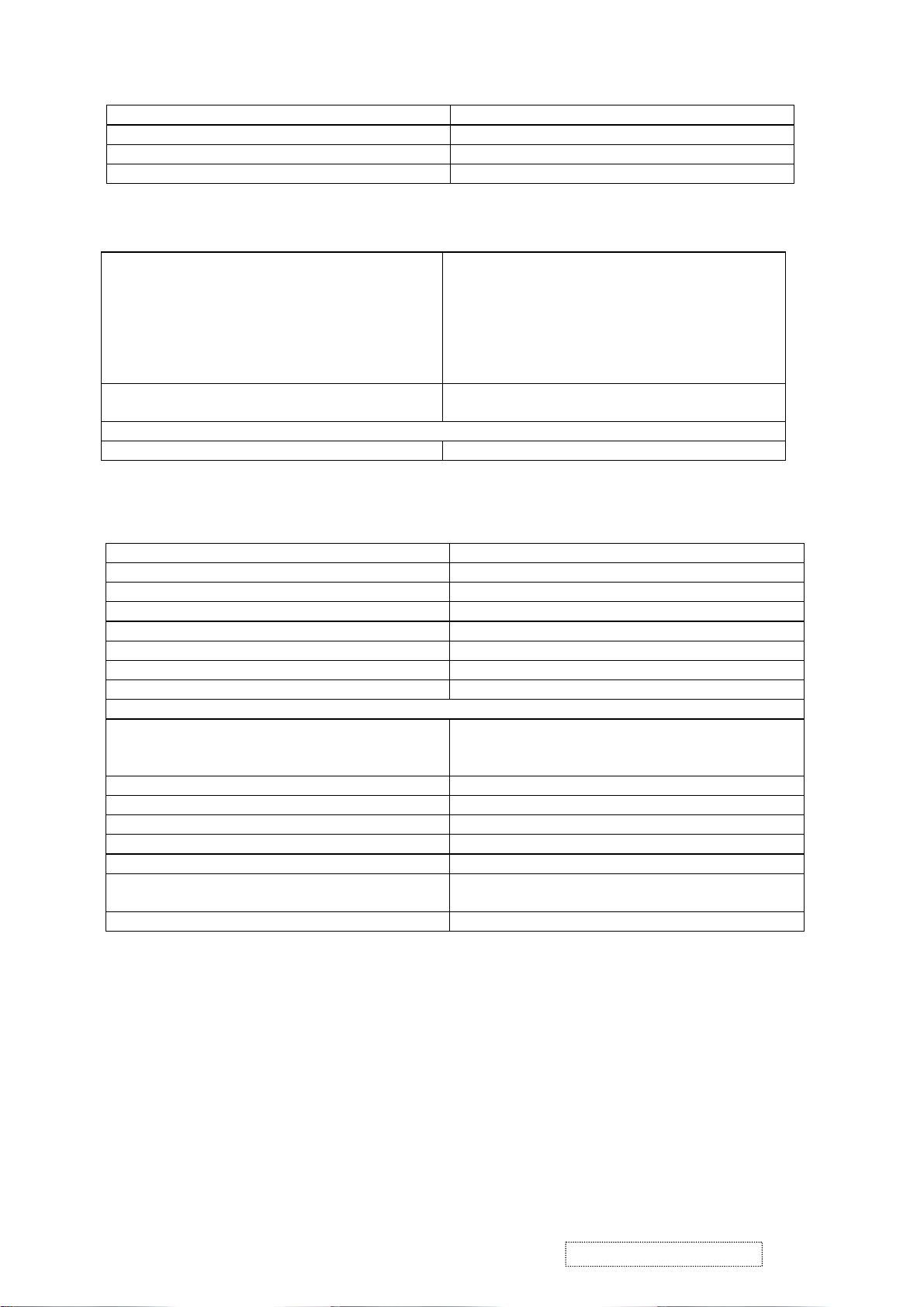
Parking For Shipping
1. Parking Procedure
1.1 Paste protecting film to protect the monitor. (Figure 1)
1.2 Put the montor in the PE bag and seal the bag with tape. (Figure 2)
1.3 Put the cushions on the monitor. (Figure 3)
1.4 Place the monitor into the carton and then put all the accessories into the carton. At last,
Figure 1 Figure 2
The carton and seal it with tape. (Figure 4)
Figure 3 Figure 4
ViewSonic Corporation Confidential
38
-
Do Not Copy VE175-3
Page 42

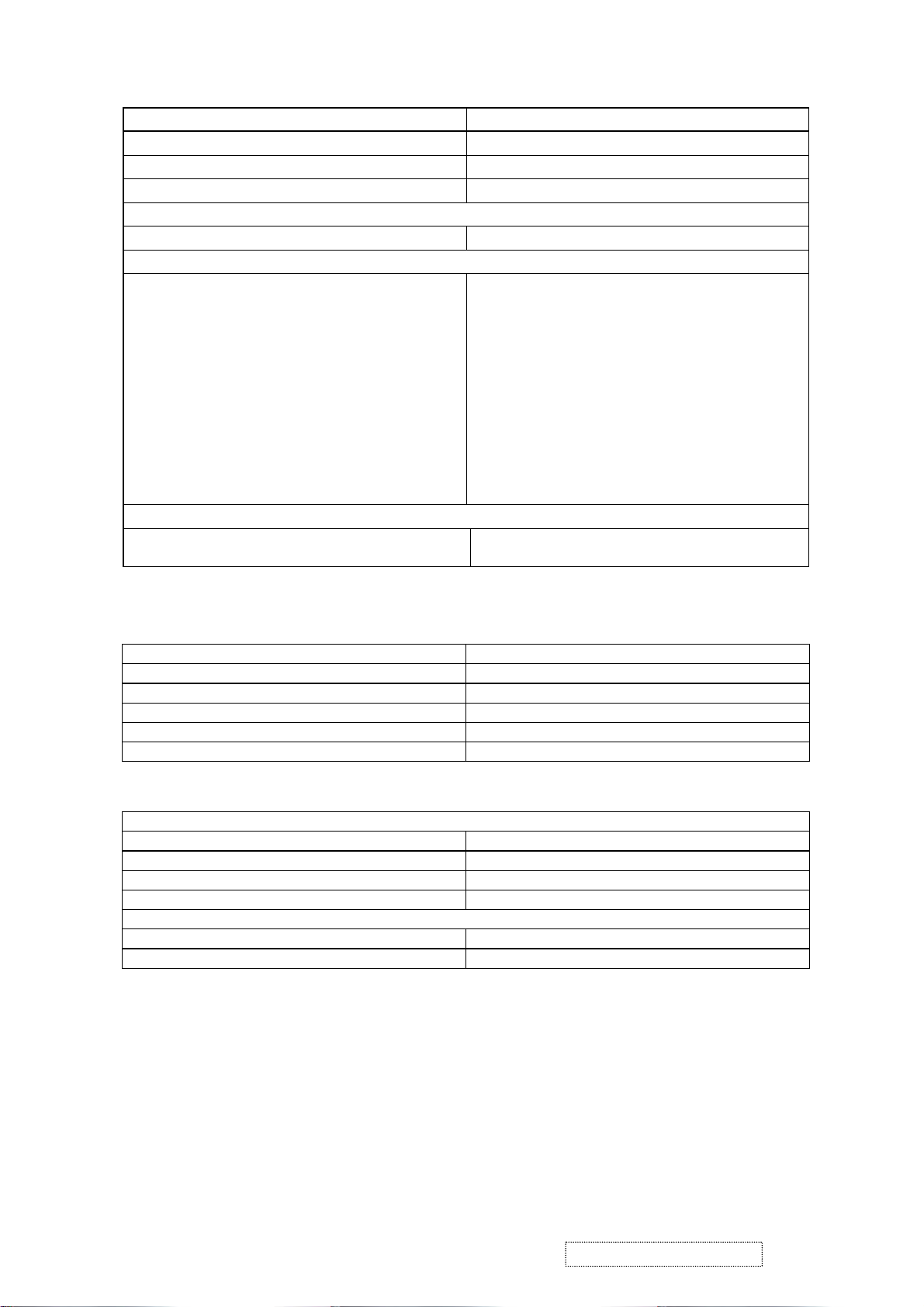
2. Disassembly
Lie down the monitor on flat table
Remove Base cover
Remove Stand
ViewSonic Corporation Confidential
39
-
Do Not Copy VE175-3
Page 43

Take out 2 screws at bottom side of CAB-B
Take out 3 screws of IF-board
Take out 2 screws at bottom side of left shielding case
ViewSonic Corporation Confidential
40
-
Do Not Copy VE175-3
Page 44

Take off power +inverter board
Take out 3 screws at bottom side of IF-board
Disassemble the Stand if need
ViewSonic Corporation Confidential
41
-
Do Not Copy VE175-3
Page 45

9. Block Diagram
INTERFACE BOARD(DPWBN5642T8----)
COMPUTER
GRAPHIC
5V
3.3V
1.8V
J1
(DB15)
X1
OSC
MCU
(U4)
MYSON
312
SW BOARD
JP1
JP7
DPWBN5614T8----
SCALER
gmZAN3L
(U2)
Serial
EEPROM
24C16
(U3)
SWITCH MODE
POWER SUPPLY
CN4 30 PIN
LVDS CABEL
JP1
TO
INVERTER
C
O
N
INVERTER+POWER
4
RUNTP5624T8----
C
O
N
5
ViewSonic Corporation Confidential
CON2
CON1
42
C
O
N
3
C
O
N
6
17” LCD
PANEL
C
0
N
1
-
Do Not Copy VE175-3
Page 46

10. Schematic Diagrams
SHEET 3
3. Input Connectors
RED+
RED-
GREEN+
GREEN-
BLUE+
BLUE-
ZAN3SL_HSYNC
ZAN3SL_VSYNC
uC_HSYNC_IN
uC_VSYNC_IN
SOG_MCSS
VGA_CAB
VGA_SDA
VGA_SCL
SHEET 4
RED+
RED-
GREEN+
GREENBLUE+
BLUE-
ZAN3SL_HSYNC
ZAN3SL_VSYNC
uC_HSYNC_IN
uC_VSYNC_IN
SOG_MCSS
VGA_CAB KEY_UP
VGA_SDA
VGA_SCL
4. gmZAN3SL
SHEET 6
6. Power&Audio
LVDS_E[0..9]
LVDS_O[0..9]
LED_GREEN
LED_ORANGE
KEY_ONOFF
KEY_RIGHT
KEY_DOWN
KEY_LEFT
BKLT_EN
BKLT_ADJUST
PPWR
PBIAS
PWM0
SW2
SW3
MUTE
AUD_ON
SRS
SRS
VOL
AUD_ON
MUTE
VOL
LVDS_E[0..9]
LVDS_O[0..9]
SHEET 5
LVDS_E[0..9]
LVDS_O[0..9]
PPWR
PBIAS
PWM0
LED_GREEN
LED_ORANGE
KEY_ONOFF
KEY_UP
KEY_RIGHT
KEY_DOWN
KEY_LEFT
SW2
SW3
BKLT_EN
BKLT_ADJUST
5. Display
ViewSonic Corporation Confidential
43
-
Do Not Copy VE175-3
Title
VE175-3
Size Document Number
DPWBN5642T8----;---A
Date:
0/19/04
Rev
Sheet
26
1
of
A
Page 47

3.3V_DVDD
VGA_+5V
D1
1 2
1N4148
J1
1
2
3
4
5
6
7
8
9
10
11
12
13
JST PHR-13 2.0 pitch 90 Degree
D2
1 2
1N4148
R1
10K
VGA_+5V
VGA-DET
VGA_SCL
A-VS
A-HS
VGA_SDA
A-BLUE
A-GREEN
A-RED
3.3V_DVDD
Q2
2
2N3906
1
R3
100k
0.1uF
15
14
13
12
11
CN1
DB15 HD/NC
D8
5.6V
MCU3V3
C3
0.01uF
17 16
GND
VGA
1 2
5
10
4
9
3
8
2
7
1
6
D9
5.6V
GNDGND
D6
5.6V
1 2
VGA_+5V
1 2
GND
VGA-DET
D5
雙
Lay
0603
+5V
R4
10K/NC
5.6V/short
1 2
GND
C16
10nF
GND
+5V
C15
10nF
GND
D10
C11
10nF
3
GND
GND
D7
+5V
100R/NC
R5
Layout two size 0805/0603
0603 / 100 R
FB1
0603 / 100 R
GND
R11 75R
R12 75R
GND
FB2
FB3
0603 / 100 R
R9
2.7K/NC
C12
10PF/NC
GND
A-BLUE
A-GREEN
A-RED
+5V
R10 75R
GND
3
GND
1 2
Near VGA pins
1 2
C13
10PF/NC
GND
R6
100R
R7
100R
R8
100R
C14
10PF/NC
GND
GND GND
1%
1%
1%
1%
120R
R13
GND
1%
120R
R14
1%
120R
R15
C4 0.01uF
C5 0.01uF
C6 0.01uF
C7 0.01uF
C8 0.01uF
C9 0.01uF
C10 0.01uF/NC
VGA_CAB 4
BLUE+ 4
BLUE- 4
GREEN+ 4
GREEN- 4
RED+ 4
RED- 4
SOG_MCSS 4
Q1
3
2
2N3906
3
1
C1
C2
10uF/16V
R2
10K
D3
5.6V
1 2
GND
D4
5.6V
1 2
GND
GND
GND
GND
U1
2
A1
3
A2WPSCL
4
GND
24C21/NC
EDID
VGA_+5V
1 2
81
VCCA0
7
6
5
SDA
BAT54C/NC
D12
3
0.1uF/NC
C17
A-VS
GND
+5V
R16
10K/NC
C20
100pF/NC
GND
GND
R17
10K/NC
C23
100pF/NC
R21
R20
100R/NC
100R/NC
ViewSonic Corporation Confidential
44
3
D11
1 2
GND
A-HS
A-VS
-
Do Not Copy VE175-3
R18 20R
R19 20R
100pF/NC
R22 75R
R23 100R
Title
VE175-3
Size Document Number
DPWBN5642T8----;---A
Date:
C18
GND
100pF
0/19/04
C21
C19
100pF/NC
GND
GND
C22
100pF
36
Sheet
ZAN3SL_HSYNC 4
ZAN3SL_VSYNC 4
uC_HSYNC_IN 4
uC_VSYNC_IN 4
VGA_SDA 4
VGA_SCL 4
Rev
of
A
Page 48

+3.3V_VDD
L1
0805/60/100M
C24
10uF/16V
C25
0.1uF
C26
0.1uF
C27
0.1uF
C28
0.1uF
C29
0.1uF
3.3V_DVDD
C30
0.1uF
+1.8V_VDD
L2
0805/60/100M
C31
10uF/16V
C32
0.1uF
C33
0.1uF
C34
0.1uF
C35
0.1uF
1.8V_DVDD
C36
0.1uF
C37
0.1uF
3.3V_DVDD
1.8V_DVDD
CN2
gProbe
DDC_SCL
DDC_SDA
GND
C52
0.1uF/NC
1
2
3
4
R58 10K/NC
GND
GND
+5V
GND
MCU3V3
R59 10K/NC
R46 10K/NC
R62 0R
R63 0R
0805/60/100M
0805/60/100M
R47 10K/NC
R51 0R/NC
R53 0R/NC
L4
L5
RXD
TXD
TXD
RXD
GND
C41
10uF/16V
GND
3.3V_LAVDD
Close to respective power Pins
C45
0.1uF
GND
MCU3V3
C54
0.1uF
GND
R54
1M
X1
12MHz
C58
C57
22pF
22pF
HCLK/ALE
WRn
GND
GND
Close to respective power Pins
3.3V_AVDD
C42
C43
C44
0.1uF
0.1uF
0.1uF
Close to respective power Pins
GND
R34
uC_HSYNC_IN3
uC_VSYNC_IN3
3.3V_DVDD
R94
MCU3V3
R60
10K
1uf
10uF/16v/NC
R61
10K
MCU3V3
R93
1uf
C53
C55
GND
SRS
GND
R55 100R
R56 100R
R52
R50
200R
100R
GND
+5V
0R
VGA_SCL
VGA_SDA3
3
U3
1
A0
2
A1
3
A2
4 5
VSS SI
24LC16B
0R
C50
0.01uF
GND GND
R95
20k
3
C56
0.1uF
GND
C47
0.1uF
VCC
WP
SCK
uC_HSYNC_IN
uC_VSYNC_IN
NVRAM_SCL
NVRAM_SDA
C51
0.1uF
U4
7
RST
8
VDD
9
P6.3/AD3
10
VSS
11
X2
12
X1
13
ISDA/P3.4/T0
14
ISDL/P3.5/T1
15
STOUT/P4.2
16
P6.2/AD2/HLFH1
17
P1.0
MTV312MV
VGA_SCL
VGA_SDA
MCU3V3
R26
10K
8
7
6
GND
6
NC
NC
VDD3
P1.1
P3.2/INT0
P1.2
1819202122232425262728
INTR
DA0/P5.0
P1.3
MCU3V3
R24 4.7K
12345
VSYNC
DA2/P5.2
DA1/P5.1
P1.4
P1.5
P1.6
R25 4.7K
HSYNC
P1.7
R27
10K
MCU3V3
100R
R36
0.01uF/NC
R41 100R
R43 100R
4041424344
DA5/P5.5
DA4/P5.4
DA3/P5.3
DA8/HLFHO
DA9/HALFV
HBLANK/P4.1
VBLANK/P4.0
DA7/HCLAMP
DA6/P5.6
P6.7/DA13
P6.6/DA12
P6.5/DA11
P6.4/DA10
Hscl/P3.0/Rxd
P6.1/AD1
P6.0/AD0
Hsda/P3.1/Txd
R64 100R
R65 100R
RN1
1 8
2 7
3 6
4 5
RN2
1 8
2 7
3 6
4 5
L3
0805/60/100M
R28 100R
R29 100R
R30 100R
R31 100R
R32
10K/NC
GND
39
38
37
36
35
34
33
32
31
30
29
44-Pin PLCC
Socket
100R
100R
GND
GND
DDC_SCL
DDC_SDA
NVRAM_SCL
NVRAM_SDA
MCU3V3
RST#
C49
MEM_REG
R57 100R
RXD
TXD
SW3
SW2
AD7
AD6
AD5
AD4
AD3
AD2
AD1
AD0
C38
10uF/16V
R39
10K
RDn
C39
0.1uF
MCU3V3
R40
10K
VGA_CAB
LED_ORANGE
LED_GREEN
KEY_ONOFF
SW3
5
SW2
5
1.8V_AVDD
C40
0.1uF
Close to respective power Pins
ZAN3SL_HSYNC3
ZAN3SL_VSYNC3
SOG_MCSS3
+5V
Refer Boot Strap Options
10K/NC
R44
R45
10K/NC
VGA_CAB 3
LED_ORANGE 5
LED_GREEN 5
KEY_ONOFF
5
INTR
GREEN+3
GREEN-3
DNP
RED+3
RED-3
BLUE+3
BLUE-3
1.8V_AVDD
TCLK
R37 100R
DDC_SCL
DDC_SDA
AD2
R48 10K
GND
3.3V_AVDD
AGND
ZAN3SL_HSYNC
ZAN3SL_VSYNC
+5V
RST#
R33
10K
AD7
AD6
AD5
AD4
AD3
AD1
AD0
R49 10K
Refer Boot Strap Options
RDn
WRn
HCLK/ALE
MEM_REG
U2
69
AVDD_ADC_3.3
79
AVDD_ADC_3.3
89
AVDD_RPLL_3.3
84
VDD_RPLL_1.8
82
VDD_ADC_1.8
81
GND_ADC
72
AGND_ADC
76
AGND_ADC
80
AGND_ADC
83
VSS_RPLL
86
AVSS_RPLL
87
XTAL
88
TCLK
77
RED+
78
RED-
74
GREEN+
75
GREEN-
70
BLUE+
71
BLUE-
95
HSYNC
96
VSYNC
73
SOG_MCSS
91
RESET_OUT
90
RESETn
46
GPIO10/IRQn
97
DDC_SCL
98
DDC_SDA
38
GPIO13/AD7
39
GPIO12/AD6
40
GPIO11/AD5
41
HFS/AD4
42
HDATA3/AD3
43
HDATA2/AD2
44
HDATA1/AD1
45
HDATA0/AD0
37
RDn
36
WRn
35
HCLK/ALE
34
MEM_REG
gmZAN3SL
33
51
94
RVDD_3.3
RVDD_3.3
RVDD_3.3
CRVSS
32486468100
CRVSS
CRVSS
GND
CRVSS
473167
92
65
99
CVDD_1.8
CVDD_1.8
CVDD_1.8
CVDD_1.8
CVDD_1.8
CRVSS
CRVSS
93
AVDD_LV_3.3
CVDD_1.8
VDD_OUT_LV_3.3
VDD_OUT_LV_3.3
VDD_OUT_LV_3.3
VSS_OUT_LV
VSS_OUT_LV
CH3P_LV_E/R0
CH3N_LV_E/R1
CLKP_LV_E/R2
CLKN_LV_E/R3
CH2P_LV_E/R4
CH2N_LV_E/R5
CH1P_LV_E/R6
CH1N_LV_E/R7
CH0P_LV_E/G0
CH0N_LV_E/G1
CH3P_LV_O/G2
CH3N_LV_O/G3
CLKP_LV_O/G4
CLKN_LV_O/G5
CH2P_LV_O/G6
CH2N_LV_O/G7
CH1P_LV_O/B0
CH1N_LV_O/B1
CH0P_LV_O/B2
CH0N_LV_O/B3
GPIO0/PWM0
GPIO1/PWM1
GPIO2/DHS
GPIO4/DEN
GPIO5/DCLK
VBUFS_RPLL
Title
Size Document Number
Date:
GPIO3/DVS
1
4
16
28
3
AVSS_LV
15
27
5
6
7
8
9
10
11
12
13
14
17
18
19
20
21
22
23
24
25
26
30
PPWR
29
PBIAS
49
NC
61
NC
66
NC
52
53
54
55
56
57
58
GPIO6/B7
59
GPIO7/B4
60
GPIO8/B6
50
GPIO9/B5
85
2
VCO_LV
62
STI_TM1
63
STI_TM2
VE175-3
DPWBN5642T8----;---A
0/19/04
GND
LVDS_E9
LVDS_E8
LVDS_E7
LVDS_E6
LVDS_E5
LVDS_E4
LVDS_E3
LVDS_E2
LVDS_E1
LVDS_E0
LVDS_O9
LVDS_O8
LVDS_O7
LVDS_O6
LVDS_O5
LVDS_O4
LVDS_O3
LVDS_O2
LVDS_O1
LVDS_O0
GND
GND
PPWR
PBIAS
SP1
SP3
3.3V_LAVDD
PWM0
VOL
R35 100R
R38 100R
SP2
SP4
GND
3.3V_DVDD
LVDS_E[0..9]
LVDS_O[0..9]
Sheet
PPWR 5
PBIAS 5
PWM0 5
VOL 6
AUD_ON 6
MUTE 6
4
of
LVDS_E[0..9] 5
LVDS_O[0..9] 5
Rev
A
6
ViewSonic Corporation Confidential
45
-
Do Not Copy VE175-3
Page 49

+12V
JP1
JP2
6
5
4
3
2
1
LVDS_O[0..9]4
1
2
*
標註記號
3
4
5
6
7
8
JST PHR-8
2.0 pitch
90 Degree
LVDS_O0
LVDS_O1
LVDS_O2
LVDS_O3
LVDS_O4
LVDS_O5
LVDS_O6
LVDS_O7
LVDS_O8
LVDS_O9
F1 4A_SMD
RFIL-5240T8110A[0805]
BL_ON/OFF
BL_ADJ
L6
+5V
RXO0RXO0+
RXO1RXO1+
RXO2RXO2+
RXOCRXOC+
RXO3RXO3+
RXE0RXE0+
RXE1RXE1+
RXE2RXE2+
RXECRXEC+
RXE3RXE3+
+5V
100uF/16V
R66
47K
3
4
PPWR
R67 1K
Q3
1
MMBT3904L
2
GND
C61
GND
+5V
+5V
FB4
0805
C62
0.1uF
SW_PANEL_PWR
R96
1K
100uF/16V-22uF
SP5
C59
GND
C60
0.1uF
U5
AP9435M
8
3
S
2
S
1
S
D
7
D
6
D
5
D
G
4
BL_ADJ
C63
1uF
LVDS_E[0..9]4
R71 4.7K
Q4
2N3904
LVDS_E0
LVDS_E1
LVDS_E2
LVDS_E3
LVDS_E4
LVDS_E5
LVDS_E6
LVDS_E7
LVDS_E8
LVDS_E9
Q5
MMBT3904L
+5V
3
2
GND
R69
10K
R73 1K
1
3
2
GND
MCU3V3
R70
10K
1
Q6
MMBT3904L
R74
1K
PBIAS
4
+5V
R68
2K
3
2
1k
R72
1
PWM0
4
BL_ON/OFF
C64
1uF/NC
GND
SW_PANEL_PWR
RXO0RXO1RXO2-
RXOC+
RXO3-
RXE0RXE1RXE2-
RXEC+
RXE3-
CN4
12
34
56
78
910
11 12
13 14
15 16
17 18
19 20
21 22
23
24
25
26
27
28
29
30
HEADER 15X2
Panel for
HannStar
SHARP
GND
RXO0+
RXO1+
RXO2+
RXOC-
RXO3+
RXE0+
RXE1+
RXE2+
RXEC-
RXE3+
JP3
1
1
2
2
3
3
4
4
5
5
6
6
OSD CON
FB5 0603
1 2
FB6 0603
1 2
FB7 0603
1 2
FB8 0603
1 2
FB9 0603
1 2
C65
0.1uF
R87
10K
C66
0.1uF
GND
R88
10K
C67
0.1uF
C68
0.1uF
R81 100R
R83 100R
R84 330R
R85 330R
R86 100R
C69
0.1uF
ViewSonic Corporation Confidential
46
182736
45
RN3
4.7K*4
SW2
SW3
LED_O
LED_G
KEY_ONOFF
-
Do Not Copy VE175-3
2
3
Q7
2N3906
R80
4.7K
1
R78
4.7K
LED-ORANGE
2
3
R82
Q8
4.7K
1
2N3906
R79
4.7K
LED-GRN
KEY_LCD_ONOFF
SW3
SW2
LED-GRN
LED-ORANGE
4
KEY_ONOFF
SW3
4
SW2
4
LED_GREEN
LED_ORANGE 4
PCB Mounting Holes
4
M1
M2
M3
M4
GND
Title
VE175-3
Size Document Number
DPWBN5642T8----;---A
0/19/04
Date:
Sheet
56
Rev
of
A
Page 50

+5V
C70
100uF/16V
AIC1117-3.3
3 2
VI VO
C71
0.1uF
C72
0.1uF
+3.3V_VDD
C73
100uF/16V
U6
GND
1
R89
120 1%
1Vf
*
D13
1 2
DL4001SMCT
1Vf
D14
1 2
DL4001SMCT/NC
GND
C74
100uF/16V
GND
GND
Higher Amperage regulator for 3.3V_DVDD is required to
support the inrush current for 3.3V Panels
U7
AIC1117-1.8
3 2
VI VO
C75
0.1uF
GND
GND
1
GND
R90
200 1%
GND
GND
R91
220 1%
R92
100 1%
GND
C76
0.1uF
GND
+1.8V_VDD
C77
100uF/16V
GND
Power Configuration:
U11
Fixed
R107=120 ohms 1%
R108=200 ohms 1%
R107=NC
R108= 0 ohm
Adjustable
U12
R109=120 ohms 1%
R110=200 ohms 1%
R109=NC
R110= 0 ohm
pitch_ 1.5
JP4
1
2
3
4
AUD_ON
4
VOL
4
MUTE
4
SRS
4
ViewSonic Corporation Confidential
47
+5V
+12V
DGND
-
Do Not Copy VE175-3
J2-1
1
1
2
J2
1
2
3
4
5
2
1.5Pitch 90 Degree
J2-2
1
1
2
2
Note: All capacitors without specified value
are 85 C type.
All C's not otherwise specified are
50V type.
All resistorwich are not otherwise
specified are 1/6W.
共
Lay
Title
VE175-3
Size Document Number
DPWBN5642T8----;---A
Date:
0/19/04
Sheet
66
Rev
of
A
Page 51

11. PCB Layout Diagrams
MAIN BOARD
ViewSonic Corporation Confidential
48
-
Do Not Copy VE175-3
54
Page 52

CONTROL BOARD
ViewSonic Corporation Confidential
49
-
Do Not Copy VE175-3
Page 53

POWER BOARD
ViewSonic Corporation Confidential
50
-
Do Not Copy VE175-3
Page 54

ViewSonic Corporation Confidential
51
-
Do Not Copy VE175-3
Page 55

*Readers Response*
Dear Readers:
Thank you in advance for your feedback on our Service Manual,which allows continuous improvement
of our products. We would appreciate your completion of the Assessment Matrix below, for return to
ViewSonic Corporation.
Assessment
A.What do you think about the content after reading VE175-3 Service Manual?
1.
Precautions And Safety Notices
2. Specification
Front Panel Function Control Description
3.
4. Circuit Description
5.
Adjusting Procedure
6. Trouble Shooting Flow Chart
7. Recommended Spare Parts List
8. Exploded Diagram and Spare Parts List
9. Block Diagram
10. Schematic Diagrams
11. PCB Layout Diagrams
tinU riaF daB
B.Are you satisfied with the VE175-3 service manual?
metI tnellecxE dooG riaF daB
dooGtnellecxE
.1
Service Manual Content
.2
Service Manual Layout
.3
The form and listing
C.Do you have any other opinion or suggestion about this service manual?
Readers basic data:
Name: Title:
Company:
Add.:
Tel:
E-mail:
After completing this form, please return it to ViewSonic Quality Assurance
1-909-839-7943.
(marc.maupin@viewsonic.com)
You may also e-mail any suggestions to the Director, Quality Systems & Processes
Fax:
in the USA at facsimile
ViewSonic Corporation Confidential
52
-
Do Not Copy VE175-3
 Loading...