

Page 1

Service Manual
ViewSonic VPW505
ModelNo.VPLSM24288-1W
50" XGA Plasma Panel Display
(VPW505_SM_708 Rev. 1a Jun_ 2003)
ViewSonic ® 381 Brea Canyon Road, Walnut, California 91789 USA - (800) 888-8583
Page 2
Copyright
¤
Copyright
reproduced, transmitted, transcribed, stored in a retrieval system, or translated into any language or
computer language, in any form or by any means, electronic, mechanical, magnetic, optical, chemical,
manual or otherwise, without the prior written permission of ViewSonic Corporation.
Disclaimer
ViewSonic makes no representations or warranties, either expressed or implied, with respect to the contents
hereof and specifically disclaims any warranty of merchantability or fitness for any particular purpose.
Further, ViewSonic reserves the right to revise this publication and to make changes from time to time in the
contents hereof without obligation of ViewSonic to notify any person of such revision or changes.
Trademarks
ViewSonic is a registered trademark of ViewSonic Corporation.
All other trademarks used within this document are the property of their respective owners.
2003 by ViewSonic Corporation. All rights reserved. No part of this publication may be
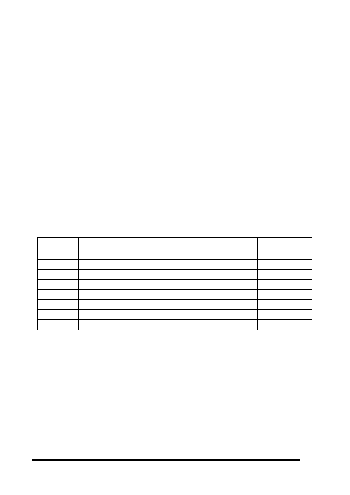
Revision History
Revision Date Description Of Changes Approval
1
a
6/06/03 Initial Release - DCN3574 J. Wu
Page 3

CONTENTS
1. IMPORTANT SAFETY PRECAUTIONS..……….1.1
2. SPECIFICATION….......................................2.1-2.10
3. FACTORY & ELECTRONIC ADJUSTMENT..3.1-3.2
4. BLOCK DIAGRAM………………...................4.1- 4.6
5. TROUBLE SHOOTING GUIDES…………...5.1 - 5.6
6. SCHEMATIC DIAGRAM…………………….6.1 - 6.22
7. P.C.BOARD TOP VIEW….…………………7.1 - 7.11
8. RECOMMENDED SPARE PARTS LIST…..8.1 - 8.3
9. EXPLODED VIEW………………….………………9.1
10.PACKING OF THE LIST…………………………10.1
ViewSonic Corporation
Confidential – Do Not Copy
Page 4

IMPORTANT SAFETY PRECAUTIONS Ver1.0
1. Before return ing an instrument to the customer,
always make a saf ety check of the entire instrument,
including, but not limited to, the following items.
a.
Be sure that no built-in protective devices are defective and/or have been defeated during servicing. (1)
Protective shields are provided on this chassis to protect both the technician and the customer. Correctly
replace all mis sing protec tive sh ields, including an y removed f or ser vicing con venienc e. (2) W hen reins talling
the chassis and/or other assembly in the cabinet, be sure to put back in place all protective devices, including,
but not limited to, nonmetallic control knobs, insulating fish papers, adjustment and compartment
covers/shields, and is olation res istor/capacit or networks.
Do not operate this instrument or permit it to be
operated without all protective devices correctly installed and functioning.
b.
Be sure that there are no cabinet openings through which an adult or child might be able to insert their
fingers and contact a ha zardous voltage, Such opening inc lude, but are not lim ited to, (1) spac ing between
the picture tube and the c abinet mask , (2) excessively wide ca binet ventilation sl ots, and (3) an improper ly
fitted and/or incorrectly secured cabinet back cover.
c. Leakage Current Hot Check
—
—With the instr ument completely reas sembled, plug the AC line cord directly
——
into a 120V AC out let . (Do not use an isolatio n tr a nsformer during this tes t.) Us e a l eakage current tester or a
metering system that com plies with American Nati onal Standards Institutes (ANSI) C101.1 Leakage Cur rent
for Appliances and U nderwriters Laboratories ( UL) 47 8 . W ith the ins tr ument AC switch firs t in t he O N pos it io n
and then in the OFF position, m easure from a known earth ground (metal water pipe, conduit, etc.) to all
exposed metal parts of the instrument (antennas, handle bracket, metal cabinet, screw heads, metallic
overlays, control sh afts, etc.), especially any exposed m etal parts that offer an electrical return path to th e
chassis. Any cur rent m easured m us t not ex cee d 3.5 m illiam p. Rev erse t he ins tr um ent power cord plu g in the
outlet and repeat test.
ANY MEASUREMENTS NOT WITHIN T HE LIMITS SPECIFIED HEREIN INDIC ATE
A POTENTIAL SHOCK HAZARD THAT MUST BE ELIMINATED BEFORE RETURNING THE
INSTRUMENT TO THE CUSTOMER.
AC Leakage Test
DEVICE
UNDER
TEST
TEST ALL
EXPOSED METAL
SURFACES
3. WIRE CORD
ALSO TEST WITH
PLUG REVERSED
(USING AC ADAPTER
PLUG AS REQUIRED)
LEAKAGE
CURRENT
TESTER
+ -
(READING
SHOULD NOT
BE ABOVE
3.5mA)
EARTH
GROUND
2.
Read and comply with al l caution and s afety-re lated notes on or inside th e Mon itor cabinet, on th e Project ion
Monitor chassis, or on the picture tube.
3. Design Alteration Warning
—
—Do not alter or add to the mechanical or electrical design of this unit. Design
——
alterations and additio ns, including , but not limited to, circuit modif ications and th e addition of the item s such
as auxiliary audio and/or video output connections might alter the safety characteristics of this Projection
Monitor and create a hazard to the user. Any design alterations or additions will void the manufacturer’s
warranty and will make you, the service, responsible for personal injury or property damage resulting
therefrom.
ViewSonic Corporation
Confidential – Do Not Copy
1-1
Page 5

IMPORTANT SAFETY PRECAUTIONS Ver1.0
4. Hot Chassis Warning
AC power cord and may be safely serviced without an isolation transformer only if the AC power plug is
inserted so that the c hassis is c onnected to the gr ound side of the AC power so urce. To confirm that the AC
power plug is inserted correctly, with an AC voltm eter measure between the chassis and a known earth
ground. If a voltage read in g in ex c es s of 1.0V is o bta in ed, r emove and reinsert t he AC po wer pl ug i n op pos it e
polarity and again m easure the voltage potent ial between the chass is and a known earth gr ound. b. Some
Monitor chassis norm all y have 85V AC (RMS.) , bet ween c hassis a nd ear th gr oun d regard less of the A C plug
polarity. These chassis can be safely service d only with an isolation transformer inserted in the power line
between the receiv er and the AC power source, for both personnel a nd test equipm ent protection.
Projection Monitor chass is have a secondary ground system s in addition to the main chassis ground. T his
secondary ground system is not isolated from the AC power line. The two ground system are electrically
separated by insulating material that must not be defeated or altered.
5.
Observe original lead dress. Take extra care to assure correct lead dress in the f ollowing areas:
sharp edges, b. near thermall y hot parts—be sure that le ads and components do not touch thermall y hot
c.
parts,
out-of-place, or fr ayed wiring. Do not chan ge spacing bet ween components, an d between com ponents and
the printed-circuit board. Check AC power cord for damage.
6.
Components, parts, and/or wiring that appear to have overheated or are otherwise damaged should be
replaced with components, parts, or wiring that meet original specifications. Additionally, determine the
cause of overheating an d/or dam age and, if neces sar y, take corrective action to rem ove any pote ntial saf ety
hazard.
7. PRODUCT SAFETY NOTICE
characteristics som e of which are often not evident from visual ins pection, nor can the protection they give
necessarily be ob tained b y replacin g them with com ponents rated for higher voltage, wattag e, etc. Parts th at
have special safety characteristics are identified in this service data by shading with a mark on
schematics and b y shading or a * mark in the parts l ist. Use of a substi tute repl acem ent part that d oes not
have the same safety characteristics as the recommended replacement part in this service data parts list
might create shock, fire, and/or other hazards.
the AC supply,
a.
————
Some Monitor chassis are electrically connec ted directly to one conduc tor of the
d.
high voltage,
—
—Many Monitor electrical and mechanical parts have special safety-related
——
e.
antenna wiring. Always inspect in all areas for pinched,
c.
a.
Some
near
ViewSonic Corporation
Confidential – Do Not Copy
1-2
Page 6

SPECIFICATION FOR VPW505 PLASMA DISPLAY VER1.0
1. SCOPE:
These specifications describe all the characteristics of the 50 inch color monitor.
2. ELECTRICAL REQUIREMENTS:
2.1. Display panel: Specification
a. Screen size Diagonal 50 inch
b. Aspect ratio 16:9 wide
c. Number of pixels 1366(Horizontal, RGB Trio ) X 768(Vertical)pixels
d. Pixel Pitch 0.81mm X 0.81mm
e. Luminance 620cd/m
f. Chromatically
2.2. Power Source:
a. Input voltage 100 ~ 240 Vac , 50 / 60 Hz
b. Input current 5.0 A
c. Inrush current 60 A p-p/20ms Max.
d. Power consumption
x=0.270
at center block white pattern 100% (mosaic).
x=0.280
at center block white pattern 100% (mosaic).
x=0.332
at center block white pattern 100% (mosaic).
x=0.313
at center block white pattern 100% (mosaic).
550 Watts MAX ( at 110Vac/all white pattern)
2
,at APL13%
0.03, y=0.270
±±±±
0.03, y=0.300
±±±±
0.03, y=0.338
±±±±
0.03, y=0.329
±±±±
0.03(color temperature HIGH )
±±±±
0.03(color temperature MID )
±±±±
0.03(color temperature LOW )
±±±±
0.03(color temperature 6500D )
±±±±
e. Stand-by & DPMS 5 Watts Max. (at 110Vac)
2.3. Input Signal:
2.3.1 Connector Type:
2.3.2 Video/S-Vi deo Signal:
a. Type Analog
b. Polarity Positive
c. Amplitude
d. Frequency
e. Input impedance 75 ohms
2.3.3 COMPONENT Signal:
a. Type Analog
b. Polarity Positive
c. Amplitude AV: 1Vp-p (with sync)
d. Frequency
Y/CB/CR
Y/PB/PR: HDTV
RCA Jack for audio, video Y/C
6 pin Din S-terminal
9 pin D-SUB
15 pin D-SUB
24 pin DVI
Video 1Vp-p , (priority S-Video) Y=1Vp-p C=0.286Vp-p
H: 15.734KHz V: 60Hz(NTSC)
H: 15.625KHz V: 50Hz(PAL)
S-Video: Y: 1Vp-p ,C: 0.286Vp-p
H: 15.734KHz ,V: 60Hz (NTSC)
H: 15.625KHz ,V: 50Hz (PAL)
1. 31KHz/60Hz (480P)
2. 45KHz/60Hz (720P)
3. 33KHz/60Hz(1080I)
and Y/PB/PR
B/CR
ViewSonic Corporation
2-1
Confidential – Do Not Copy
Page 7

SPECIFICATION FOR VPW505 PLASMA DISPLAY VER1.0
2.3.4 RGB Signal:
a. Type TTL
b. Polarity Positive or Negative
c. Amplitude RGB: 0.7Vp-p
d. Frequency
2.3.5 DVI Signal:
H: support to 31K~91KHz
V: support to 50~85Hz
a. Type
b. Polarity
c. Frequency
2.3.6 Audio Signal: Analog 500mV rms /more than 22Kohm
2.3.7 Pin Assignments For D-SUB Connector (In / Loop Out):
Pin Signal Assignment Pin Signal Assignment Pin Signal Assignment
1 RED 6 RED GND 11 GND
2 GREEN 7 GREEN GND 12 SDA
3 BLUE 8 BLUE GND 13 H-SYNC
4 GND 9 NC 14 V-SYNC
5 GND 10 GND 15 SCL
2.3.8 Pin Assignments For 24 Pin DVI Connector (Digital Only):
Pin Signal Assignment Pin Signal Assignment Pin Signal Assignment
1 TMDS Data 2- 9 TMDS Data 1- 17 TMDS Data 02 TMDS Data 2+ 10 TMDS Data 1+ 18 TMDS Data 0+
3 TMDS Data 2/4
Shield
4 TMDS Data 4- 12 TMDS Data 3- 20 TMDS Data 55 TMDS Data 4+ 13 TMDS Data 3+ 21 TMDS Data 5+
6 DDC Clock 14 +5V Power 22 TMDS Clock Shield
7 DDC Data 15 Ground (For +5V) 23 TMDS Clock +
8 No Connect 16 Hot Plug Detect 24 TMDS Clock -
Digital
Positive or Negative
H: support to 31K~68KHz
V: support to 50~85Hz
11 TMDS Data 1/3 Shield 19 TMDS Data 0/5 Shield
ViewSonic Corporation
2-2
Confidential – Do Not Copy
Page 8
SPECIFICATION FOR VPW505 PLASMA DISPLAY VER1.0
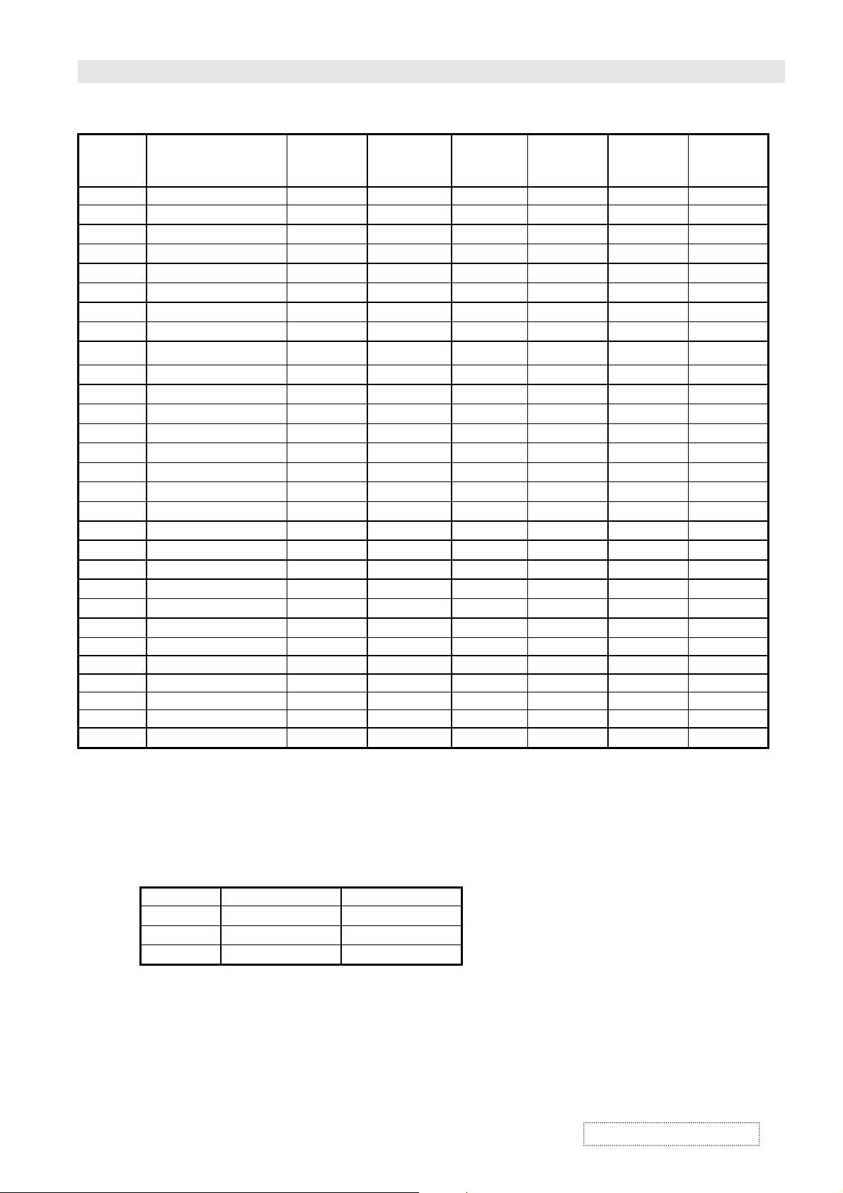
2.3.9 MODE LIST FOR RGB/DVI :
Mode No Resolution
(Hz) (K Hz) (Hz) (TTL) (TTL) (MHz)
1
2
3
4
5
6
7
8
9
10
11
12
13
14
15
1280(SXGA)
◎◎◎◎
16
1280(SXGA)
◎◎◎◎
18
19
20
21
22
23
24 640 x 480 67 35.00 66.67 - - 30.240
25 832 x 624 75 49.73 74.55 - - 57.283
26 1152 x 870 75 68.68 75.06 - - 100.000
28 1360 x 768 60 47.368 59.960 - + 72.000
30 1280 x 960 60 60.00 60.00 + + 108.000
31
◎◎◎◎
640(VGA)
640(VGA)
640(VGA)
640(VGA)
800(SVGA)
800(SVGA)
800(SVGA)
800(SVGA)
800(SVGA)
1024(XGA)
1024(XGA)
1024(XGA)
1024(XGA)
1280(SXGA)
720(DOS)
640(VGA)
1280(HDTV)
1920(HDTV)
640(VGA)
852(WGA)
1280 x 960 85 85.938 85.002 + + 148.500
480
××××
480
××××
480
××××
480
××××
600
××××
600
××××
600
××××
600
××××
600
××××
768
××××
768
××××
768
××××
768
××××
1024
××××
1024
××××
1024
××××
400
××××
480
××××
720P
××××
1080I
××××
350
××××
480
××××
Refresh
Rate
60 31.5 59.94 - - 25.175
72 37.9 72.81 - - 31.500
75 37.5 75 - - 31.500
85 43.3 85.01 - - 36.000
56 35.1 56.25 + + 36.000
60 37.9 60.317 + + 40.000
72 48.1 72.19 + + 50.000
75 46.9 75 + + 49.500
85 53.7 85.06 + + 56.250
60 48.4 60.01 - - 65.000
70 56.5 70.07 - - 75.000
75 60.0 75.03 + + 78.750
85 68.7 84.99 + + 94.500
60 63.98 60.02 + + 108.00
75 79.98 75.03 + + 135.00
85 91.15 85.02 + + 157.50
70 31.46 70.08 + - 28.322
50 31.50 50.00 - - 25.175
60 45.00 60.00 + + 74.250
60(I) 33.75 60.00 + + 74.250
70 31.50 70.00 - - 25.175
60 31.72 60.41 - - 30.000
Horizontal
Frequency
Vertical
Frequency
Vertical
Sync
Polarity
Horizontal
Sync
Polarity
Dot rate
Attention
2.3.10 Y/P
B/PR
Mode No Resolution Refresh Rate
1
2
3
: For DVI is not supported.
◎◎◎◎
For Component:
640
1920
1280
ViewSonic Corporation
480P
××××
1080I
××××
720P
××××
60
60
60
2-3
Confidential – Do Not Copy
Page 9

SPECIFICATION FOR VPW505 PLASMA DISPLAY VER1.0
2.4. Display Performance Requirements:
The data of display performance are measured based on the following
conditions unless otherwise specified.
a. Ambient temperature
b. Warm up period 30 minutes Min.
c. Line input voltage : 100 Vac ~ 240 Vac (50 / 60 Hz)
d. Viewing distance Distance from screen is 81 cm
e. Display mode Tes t with window white pattern mode if not specified.
f. Brightness condition Press recall bottom to set default brightness
2.4.1 Maximum Resolution: Support to 1280 x 1024
2.4.2 Horizontal Size (Standard) 1106.5
Vertical Size (Standard) 622.1
2.4.3 Maximum Brightness Level: Timing Mode 1
a. 100% center block white
pattern(mosaic)
b. Raster background
2.5. Operation:
Main unit button
IR Remote Control
25
5
±±±±
℃℃℃℃
8 mm (for mode 1
±±±±
8 mm (for mode 1
±±±±
More than 30FL
(while pressing recall button to set default brightness)
Less than 0.4FL
(while pressing recall button to set default brightness)
Main power switch (power ON /OFF)
Power ON/OFF
Input Select (TV -> AV1 ->AV2[S] -> COMPONENT 1 ->
COMPONENT 2-> RGB -> DVI->TV run in circle)
Menu key -,+
Adjustment -,+
Power on/off
MUTE
Display
Input Select (same as Main unit button)
Volume -,+
Wide :
TV/AV1/AV2[S]/COMPONENT 1/2
PANORAMA/4:3/16:9
(ZOOM1/ZOOM2/ZOOM3/OFF For 16:9 Only)
Analog RGB input : 4:3/16:9
Menu -,+
Adjustment -,+
RECALL
PIP ,SOURCE,SWAP,POSITION
USE FOR TV MODE:
V-CHIP
FAV.CH,FAV.SET,QV,CCD,MTS,CH LOCK,
SLEEP TIMER,
Number Select, CH
DIRECT KEY:
POWER ON,POWER
OFF,RGB,TV,AV1,AV2,COMPONENT1/2,DVI
SET
////
〜〜〜〜
〜〜〜〜
31)
31)
▲▼
▲▼
▲▼▲▼
input:
ViewSonic Corporation
2-4
Confidential – Do Not Copy
Page 10

SPECIFICATION FOR VPW505 PLASMA DISPLAY VER1.0
2.5.1Adjustable Items
TV /AV1 /AV2[S] /
COMPONENT 480I
COMPONENT
input
480P/720P/1080I
Analog RGB input
DVI input
input
PICTURE:
Input Source, Brightness, Contrast, Color, Tint, Sharpness
Color Temperature, Clock Phase, Screen Wide, Zoom
SOUND:
Bass, Treble, Surround, BBE, Bass Extension, Volume,
INNER SPK, Audio Output
PIP:
Source, Position, Swap
POP:
Source, Screen Rate, Swap
TV:
Channel, Channel Status, MTS, CCD, V-CHIP, Ch Search,
Tuner Source, Background
OTHER:
OSD Timeout, OSD Brightness, OSD Background, Sleep,
Power Saving(these mode is not use)
PICTURE(same as TV/AV1/AV2[S]/COMPONENT 480I input )
SOUND(same as TV/AV1/ AV2[S]/COMPONENT 480I
PIP/POP(this mode is not use)
TV(same as TV/AV1/AV2[S]/COMPONENT 480I
OTHER(same as TV/AV1/AV2[S]/COMPONENT 480I
PICTURE:
Input Source, Brightness, Contrast, V-center, V-size,
H- position, H-width, Color Temperature, Clock Phase
SOUND(same as TV/AV1/AV2[S]/COMPONENT 480I
PIP/POP(this mode is not use)
TV(same as TV/AV1/AV 2[S]/COMPONENT 480I input )
OTHER:
OSD Timeout, OSD Brightness, OSD Background, Sleep,
Power Saving
PICTURE:
Input Source, Brightness, Contrast, V-center, V-size, Hposition, H-width, Color Temperature
SOUND(same as TV/AV1/AV2[S]/COMPONENT 480I
PIP/POP(this mode is not use)
TV(same as TV/AV1/AV2[S]/COMPONENT 480I
OTHER:
OSD Timeout, OSD Brightness, OSD Background, Sleep,
Power Saving
input )
input )
input )
input )
input )
input )
3. DIMENSIONS: Without/Stand With/Stand
Width
Height
Depth
1256mm
762 mm
107.5mm
1256mm
810mm
300 mm
3.1. Package Dimensions:
Width 1436 mm
Height 1125 mm
Depth 470 mm
3.2. Weight:
Net weight 103.6lbs/47 Kgs (w/o stand) 108lbs/ 49Kgs (w/ stand)
Gross weight 132.24lbs/60 Kgs
ViewSonic Corporation
Confidential – Do Not Copy
2-5
Page 11

SPECIFICATION FOR VPW505 PLASMA DISPLAY VER1.0
4.ENVIRONMENT
4.1. Operating:
Temperature
Relative humidity 20~80%
Pressure 800~1114 hpa
4.2. Non-Operating:
Temperature
Relative humidity 20~90%
Pressure 700~1114 hpa
Vibration X/Y/Z, 0.5G/10~55Hz(sweep), 10 minutes
4.3. Acoustics:
(IHF A-weighted 1meter) 50dB Max.
5. SOUND:
a. Residual hum (at volume min)
b. Practical max. Audio output (at 10% THD max.)
1.0vp-p 1K Hz input 5W +5W Max. /12 ohm
c. Sound distortion (at 250 mw 1K Hz) 1% Max.
d. Audio output (input at 1.4V
e. Max. hum (at volume max)
f. Sensitivity (at volume max. O/P 1W)
at 1KHz AV Input
g. Audio Fidelity (1KHz 0dB,corrected for emphasis characteristics)
WOOFER ON 60Hz
10KHz
BBE ON 60Hz
10KHz
WOOFER & BBE OFF 100Hz
10KHz
0~40
-20~50
)
P-P
(32~104
℃℃℃℃
℃℃℃℃
℉℉℉℉
)
500
W Max.
μμμμ
1.0 V
≧≧≧≧
1000
μμμμ
150mV
P-P
W Max.
3dB
±±±±
11dB
4dB
±±±±
6dB
±±±±
8dB
±±±±
-1dB
-1dB
3dB
±±±±
3dB
3dB
3dB
3dB
±±±±
3dB
±±±±
6. RF
6.1 RF Sensitivity (Peak)
VHF CH 2 ~ CH 13 30dB Max.
UHF CH 14 ~ CH 69 30dB Max.
CATV CH A-5 ~ CH W+29 30dB Max.
6.2 AFT Pull-In Range
VHF CH 2 ~ CH 13
UHF CH 14 ~ CH 69
CATV CH A-5 ~ CH W+29
6.3 Picture IF Rejection
VHF CH 2 ~ CH 13 50dB Min.
UHF CH 14 ~ CH 69 50dB Min.
CATV CH A-5 ~ CH W+29 50dB Min.
6.4 Picture Image Rejection
VHF CH 2 ~ CH 13 40dB Min.
UHF CH 14 ~ CH 69 35dB Min.
CATV CH A-5 ~ CH W+29 35dB Min.
0.6MHz Min.
±±±±
0.6MHz Min.
±±±±
0.6MHz Min.
±±±±
ViewSonic Corporation
Confidential – Do Not Copy
2-6
Page 12
SPECIFICATION FOR VPW505 PLASMA DISPLAY VER1.0
6.5 AGC Characteristics
AGC Figure Of Merit 50dB Min.
RF signal range in which video at PDP drops 6 dB from output level obtained
with 100mV input.
6.6 RF AGC Cut In Level
6.7 FM/AM Rejection (100mV at SIF input) 14dB min
6.8 Noise Limits Sensitivity VHF 45dB max
7. Reliability Requirement:
The MTBF needs 20000hrs under operation 25
8. REGULATORY REQUIREMENTS:
8.1 Safety Requirement:
a. UL Safety of information technology equipment including
electrical business equipment
b. CSA
c. TUV
8.2 Emission Requirement:
The unit shall meet the EMI limits in all screen modes. For EMI testing, the unit must be failed
with the screen pattern consisting of scrolling capital “H” characters also the brightness
contrast will be adjusted to max. Level.
Safety of information technology equipment including
electrical business equipment
55dB
UHF 49dB max
5
(half luminosity, motion picture)
±±±±
℃℃℃℃
2dB
±±±±
a. FCC class B part 15
8.3 Transit test
a. Drop Test 200mm max.
b. Vibration Test
1. Forward and backward
2. Right and left
3. Up and down
8.4 Power Management:
Mode H-sync V-sync Video Power dissipation
Normal Pulse Pulse Active Normal power
Stand-by No pulse No pulse No video Power off
This Plasma display is Energy star compliant when used with a computer equipped with DPMS.
Note: The power indicator LED color is green in normal state, yellow in stand-by and
power saving state.
9. VIDEO
Pulse No pulse Power saving
No pulse Pulse
30 minutes 1000 c.p.m
30 minutes 1000 c.p.m
30 minutes 1000 c.p.m
Blanked Less than 5 watts
9.1 Video Signal Output
(input signal at 1.0 Vp-p
ViewSonic Corporation
0.2Vp-p)
±±±±
2-7
1.0 Vp-p
0.2Vp-p
±±±±
Confidential – Do Not Copy
Page 13

SPECIFICATION FOR VPW505 PLASMA DISPLAY VER1.0
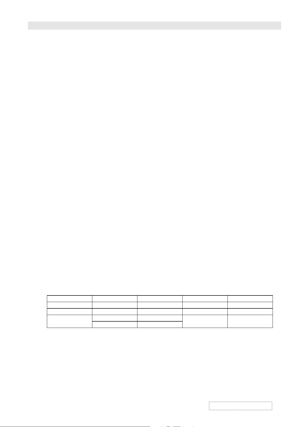
APPENDIX A :
Preset Timing Chart
Item Description:
A Total time
B Active display area including borders
C Active display area excluding borders
D Left/Top border
E Right/bottom border
F Blanking time
G Front porch
H Sync-width
I Back porch
Mode No 1 2 3 4 5 6 7 8 9
Resolution
&
Refresh Rate
Pixel Clock 25.175 31.500 31.500 36.000 36.000 40.000 50.000 49.500 56.250 MHz
Horizontal visible 640 640 640 640 800 800 800 800 800 Dots
Horizontal total 800 832 840 832 1024 1056 1040 1056 1048 Dots
Horizontal front porch 16 24 16 56 24 40 56 16 32 Dots
Horizontal sync 96 40 64 56 72 128 120 80 64 Dots
Horizontal back porch 48 128 120 80 128 88 64 160 152 Dots
Horiz blanking time 144 176 200 192 224 256 240 256 248 Dots
Vertical visible 480 480 480 480 600 600 600 600 600 Lines
Vertical total 525 520 500 509 625 628 666 625 631 Lines
Vertical front porch 10 9 1 1 1 1 37 1 1 Lines
Vertical sync 2 3 3 3 2 4 6 3 3 Lines
Vertical back porch 33 28 16 25 22 23 23 21 27 Lines
Vertical blanking time 45 40 20 29 25 28 66 25 31 Lines
Horizontal frequency 31.469 37.9 37.500 43.269 35.156 37.879 48.077 46.875 53.674 KHz
Vertical frequency 59.940 72.81 75.000 85.008 56.250 60.317 72.188 75.000 85.061 Hz
Vertical sync p olarity - - - - + + + + + TTL
Horiz sync polarity - - - - + + + + + TTL
ViewSonic Corporation
640
480
60
640
480
72
640
480
75
640
480
85
2-8
800
600
56
800
600
60
800
600
72
Confidential – Do Not Copy
800
600
75
800
600
85
Hz
Page 14
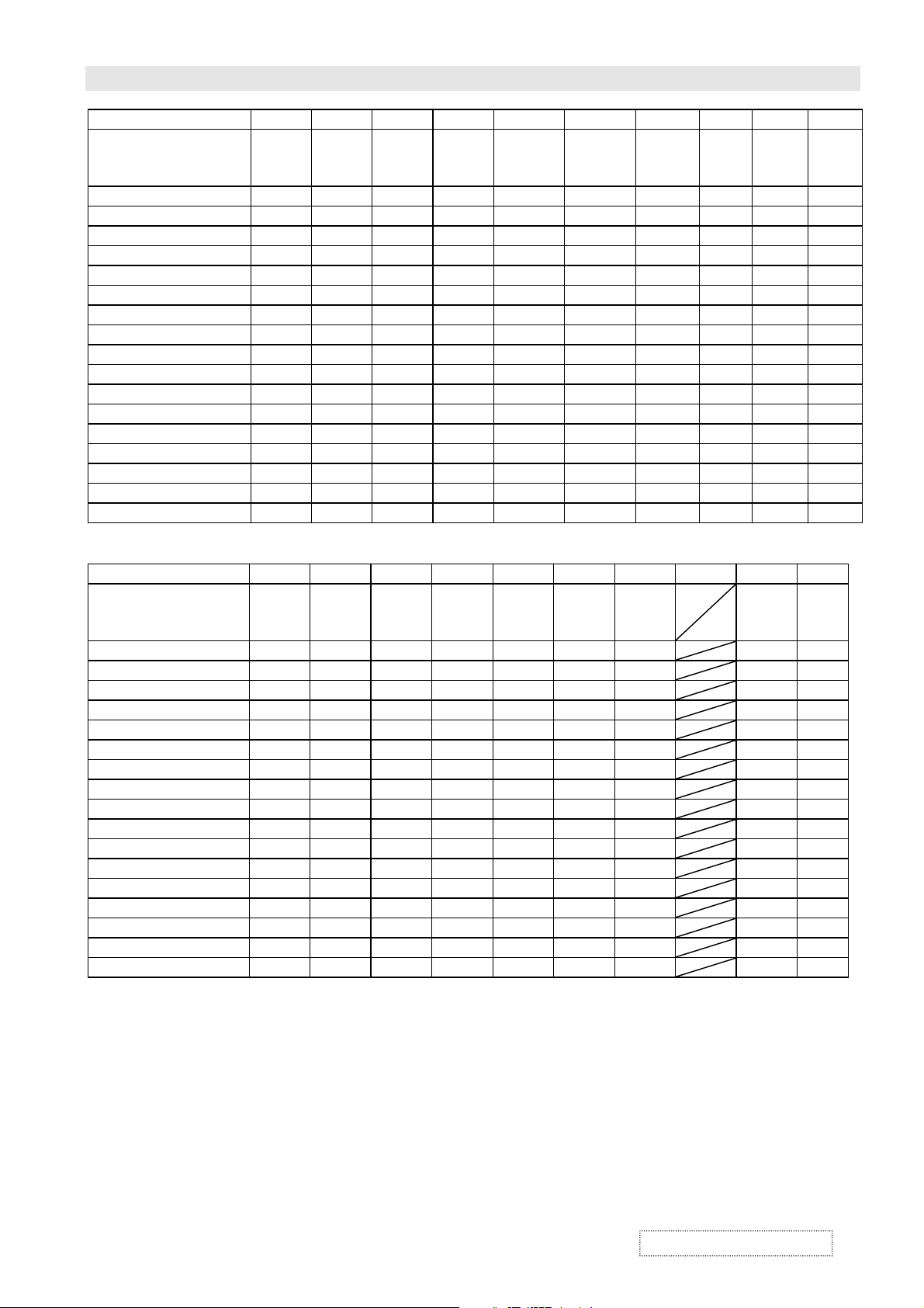
SPECIFICATION FOR VPW505 PLASMA DISPLAY VER1.0
Mode No 10 11 12 13 14 15 16 18 19
Resolution
&
Refresh Rate
Pixel Clock 65.000 75.000 78.750 94.500 108.000 135.000 157.500 28.320 25.175 MHz
Horizontal visible 1024 1024 1024 1024 1280 1280 1280 720 640 Dots
Horizontal total 1344 1328 1312 1376 1688 1688 1728 900 800 Dots
Horizontal front porch 24 24 16 48 48 16 64 18 16 Dots
Horizontal sync 136 136 96 96 112 144 160 108 96 Dots
Horizontal back porch 160 144 176 208 248 248 224 54 48 Dots
Horiz blanking time 320 304 288 352 408 408 448 180 160 Dots
Vertical visible 768 768 768 768 1024 1024 1024 400 480 Lines
Vertical total 806 806 800 808 1066 1066 1072 449 629 Lines
Vertical front porch 3 3 1 1 1 1 1 12 62 Lines
Vertical sync 6 6 3 3 3 3 3 2 2 Lines
Vertical back porch 29 29 28 36 38 38 44 35 85 Lines
Vertical blanking time 38 38 32 40 42 42 48 49 149 Lines
Horizontal frequency 48.364 56.476 60.023 68.677 63.981 79.976 91.146 31.469 31.469 KHz
Vertical frequency 60.004 70.069 75.029 84.997 60.020 75.025 85.024 70.087 50.030 Hz
Vertical sync polarity - - + + + + + + - TTL
Horiz sync polarity - - + + + + + - - TTL
1024
768
60
1024
768
70
1024
768
75
1024
768
85
1280
1024
60
1280
1024
75
1280
1024
85
720
400
70
640
480
50
Hz
Mode No 20 21 22 23 24 25 26 27 28
Resolution
&
Refresh Rate
Pixel Clock 74.250 74.250 25.175 30.000 30.240 57.283 100.000 72.000 MHz
Horizontal visible 1280 1920 640 852 640 832 1152 1360 Dots
Horizontal total 1650 2200 800 955 864 1152 1456 1520 Dots
Horizontal front porch 110 88 16 19 64 32 32 48 Dots
Horizontal sync 40 44 96 48 64 64 128 32 Dots
Horizontal back porch 220 148 48 36 96 224 144 80 Dots
Horiz blanking time 370 280 160 103 224 320 304 160 Dots
Vertical visible 720 540 350 480 480 624 870 768 Lines
Vertical total 750 562.5 449 525 525 667 915 790 Lines
Vertical front porch 5 3 37 10 3 1 3 2 Lines
Vertical sync 5 5 2 2 3 3 3 5 Lines
Vertical back porch 20 15 60 33 39 39 39 15 Lines
Vertical blanking time 30 23 99 45 45 43 45 22 Lines
Horizontal frequency 45.000 33.750 31.469 31.413 35.000 49.725 68.681 47.368 KHz
Vertical frequency 60.000 60.000 70.087 59.835 66.667 74.550 75.062 59.960 Hz
Vertical syn c polarity + + - - - - - - TTL
Horiz sync polarity + + + - - - - + TTL
1280
720P
60
1920
1080I
60I
640
350
70
852
480
60
640
480
67
832
624
75
1152
870
75
1360
768
60
Hz
ViewSonic Corporation
Confidential – Do Not Copy
2-9
Page 15

SPECIFICATION FOR VPW505 PLASMA DISPLAY VER1.0
Mode No 29 30 31
Resolution
&
Refresh Rate
Pixel Clock 108.000 148.500 MHz
Horizontal visible 1280 1280 Dots
Horizontal total 1800 1728 Dots
Horizontal front porch 96 64 Dots
Horizontal sync 112 160 Dots
Horizontal back porch 312 224 Dots
Horiz blanking time 520 448 Dots
Vertical visible 960 960 Lines
Vertical total 1000 1011 Lines
Vertical front porch 1 1 Lines
Vertical sync 3 3 Lines
Vertical back porch 36 47 Lines
Vertical blanking time 40 51 Lines
Horizontal frequency 60.000 85.938 KHz
Vertical frequency 60.000 85.002 Hz
Vertical sync polarity + + TTL
Horiz sync polarity + + TTL
1280
960
60
1280
960
85
Hz
ViewSonic Corporation
Confidential – Do Not Copy
2-10
Page 16
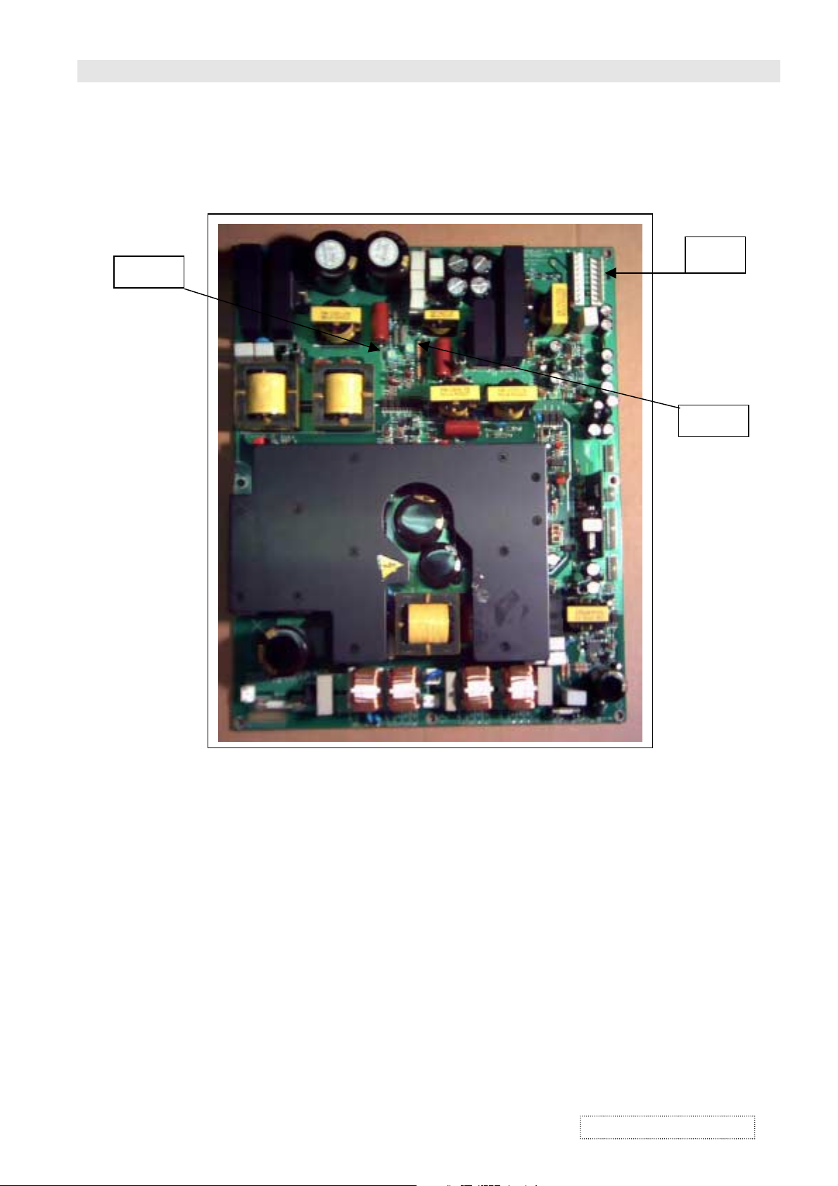
FACTORY & ELECTRONIC ADJUSTMENT VER1.0
"Vs" VR
"Va" VR
1. PANEL voltage adjustment
POWER VOLTAGE ADJUST FOR LG 50" TMDS PANEL
P805
1. POWER ON
2. INPUT ALL WHITE PATTERN
3. ADJUST "Vs" VR MEASURE P805 PIN9 TO PIN5 VOLTAGE IS 170 ~ 185 V
4. ADJUST "Va" VR MEASURE P805 PIN8 TO PIN5 VOLTAGE IS 55 ~ 65 V
ViewSonic Corporation
3-1
Confidential – Do Not Copy
Page 17

FACTORY & ELECTRONIC ADJUSTMENT VER1.0
2. Color temperature adjustment
Push the factory service key to into the adjustment mode. The picture will appear as
follow
DVI
5400ºk
X=335 Y=343
GAIN Bias
RGB RGB
XXX XXX
Use the AV key to select the color to adjust andorkey to adjust the level.
The required equipments are CA-100,Vp300.
a. Adjust Bise first to let the Y be 0.4 on CA-100. Adjust R or B to let the value of
X,Y on CA-100 be the same as the value showing screen, The value of Y
should be Maintained 0.4 during the adjusting.
b. Move the cursor to adjust Gain. The value of Y should be adjusted to 25. Then
adjust R or B to let the value of X,Y on CA-100 be the same as the value
showing on screen. The value of Y should be maintain 25 during the adjstiy.
c. Repeat to check the Bias and Gain. The value of Y,X and Y should be the
same as the previous adjusted value. Then the DVI 5400ºk mode is adjusted
completely.
d. Push the factory service key again to next picture. Then repeat the steps a. b. c.
to adjust.
e. If the adjvstment is completed, repeat d. a. b. and c steps to adjust again.
f. When the last mode AV 13000ºk is adjusted completely, push the factory
service key again to leave the adjustment mode,
Note: 1. There are 12 adjusted modes(DVIx4.RGBx4 Componentx4)
2. The adjusted sequence is DVI´RGB´Component.
3. DVI/RGB : Bias Y=0.4
Gain Y=25
Component : Bias Y=1
Gain Y=35
ViewSonic Corporation
Confidential – Do Not Copy
3-2
Page 18

BLOCK DIAGRAM VER1.0
X-Left-Top
X-Center-Top
CN1
SUB
Power
Pin[1: 4]
CN6
CN2 Pin[ 1: 3]
Pin[1: 2]
CN4
Pin[1: 6]
CN3
X-Right-Top
Z-SUS
Main Power
PB02 Pin[1: 5]
Front
Button
Control
Board Assy
Pin[1: 6]
JA3
Power SW
AC IN
Logic
Board
P100
Pin[1:40]
Pin[1:40]
J18
(TMDS)
Pin[1:48]
JP5
(9V)
Pin[1:3]
(5V)
Audio
Amplifier
Board Ass'y
Image Board
Ass'y
JP4
PinA[1:48]
J15 Pin[1:4]
(Audio DC,Suppl y)
J25
JA2
Pin[1: 10]
JA1
Pin[1: 12]
J14 Pin[1: 6]
(5V,SB DET )
Pin[1: 7]
J21
(24V,9V)
J28 Pin[1: 5]
J12 Pin[ 1: 10]
(Audio Signal)
J11 Pin[ 1: 12]
J5 Pin[1:6]
(Key)
Y-DRV-Top
Y-SUS
Y-DRV-Bottom
DC/DC
CONVERTER
X-Left-Bottom
X-Cente r -Bottom
X-Right-Bottom
AV Module
Board(with
Tuner) Assy
JP2 Pin[1: 32]
JP1
Pin[1:32]
Panel's Board Assem bly
SAMPO Board Assembl y
ViewSonic Corporation
4-1
Confidential – Do Not Copy
Page 19
BLOCK DIAGRAM VER1.0
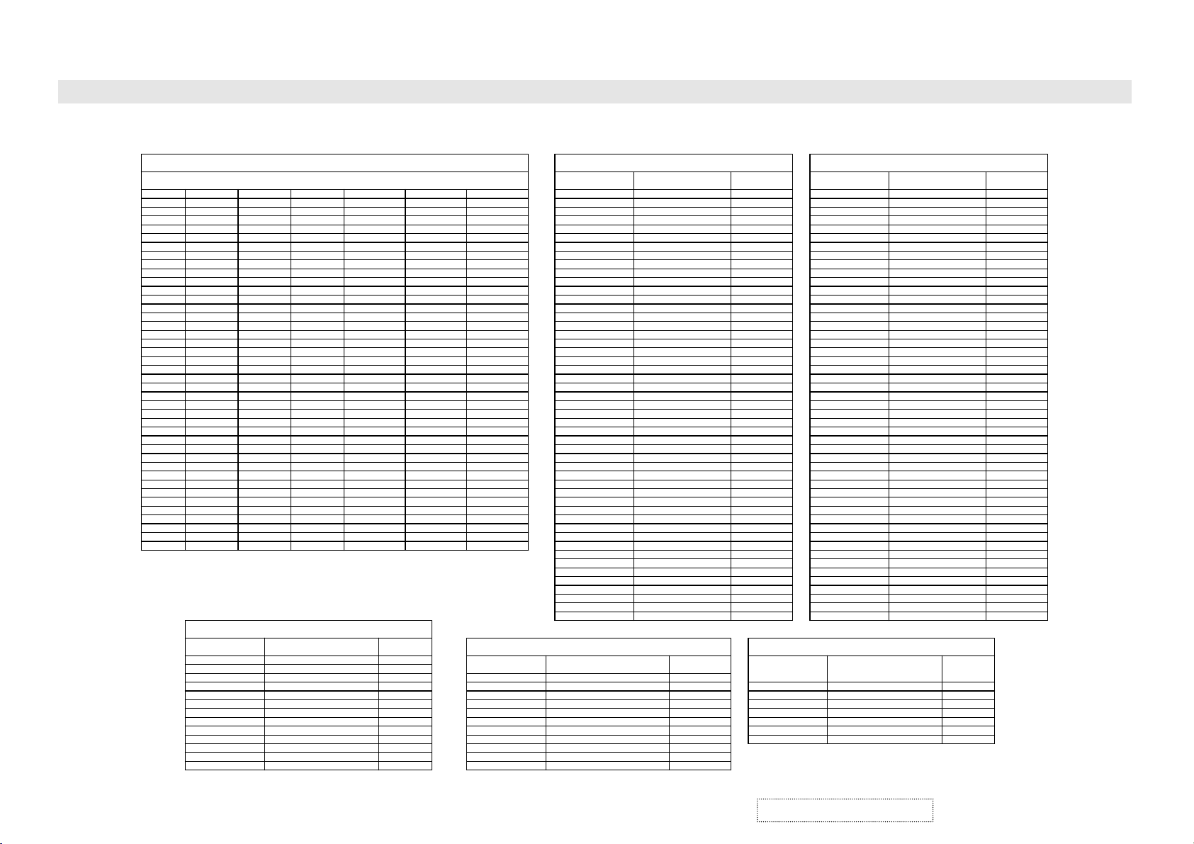
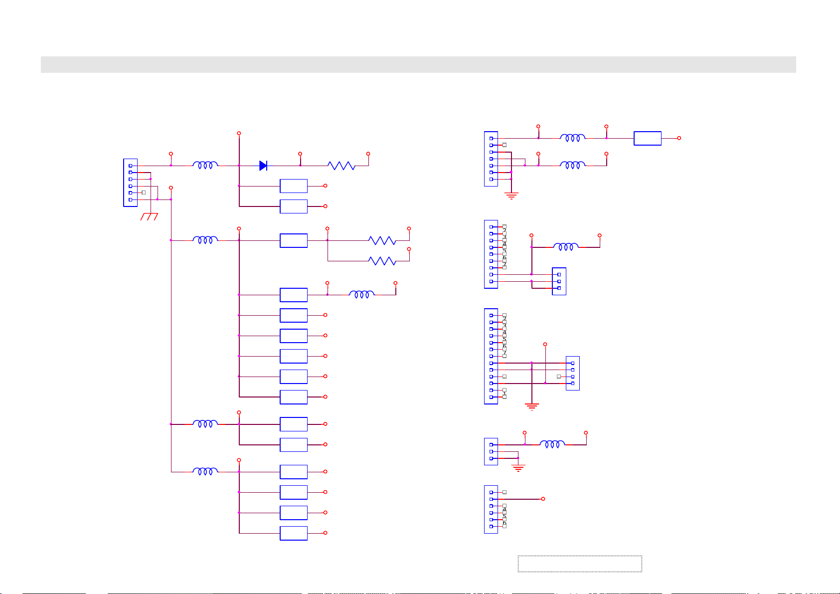
Image Board Socket Data
Image Board Ass'y
Pin 1
Pin 2
Pin 3
Pin 4
Pin 5
Pin 6
Pin 7
Pin 8
Pin 9
Pin 10
Pin 11
Pin 12
Pin 13
Pin 14
Pin 15
Pin 16
Pin 17
Pin 18
Pin 19
Pin 20
Pin 21
Pin 22
Pin 23
Pin 24
Pin 25
Pin 26
Pin 27
Pin 28
Pin 29
Pin 30
Pin 31
Pin 32
Pin 33
Pin 34
Pin 35
Pin 36
Pin 37
Pin 38
Pin 39
Pin 40
J1 (40 Pin)
GND
NC
RARA+
GND
GND
RBRB+
GND
GND
RCRC+
GND
GND
RCLK RCLK +
GND
GND
RDRD+
GND
GND
GND
GND
NC
GND
NC
GND
NC
GND
NC
NC
NC
NC
NC
NC
NC
NC
NC
NC
Image Board ←→ Audio Amplifier Board
Image Board
J11 (12 Pin)
Pin 1
Pin 2
Pin 3
Pin 4
Pin 5
Pin 6
Pin 7
Pin 8
Pin 9
Pin 10
Pin 11
Pin 12
Image Board ←→ Panel
J14 (6 Pin)
+5VSB
DGND
DGND
5V1
SB
DGND
J15 (4 Pin)
VGND
VGND
NC
+9V
Audio Amplifier Board
JA1 (12 Pin)
Pin 1
Pin 2
Pin 3
Pin 4
Pin 5
Pin 6
Pin 7
Pin 8
Pin 9
Pin 10
Pin 11
Pin 12
J21 (7 Pin)
+9VT
NC
DGND
+24V
+24V
GND
GND
Content
24V
24V
DGND
SB5V
DGND
AO_SEL
SDA2
SCL2
A_MUTEn
SURR1
SURR2
DGND
J25 (3 Pin)
+5VA
VGND
VGND
J28 (5 Pin)
SB
+5SB
VGND
AC_DET
AC_DET
Image Board
J12 (10 Pin)
Pin 1
Pin 2
Pin 3
Pin 4
Pin 5
Pin 6
Pin 7
Pin 8
Pin 9
Pin 10
Image Board ←→ AV Module Board
Image Board
JP5 (48 Pin)
A1
A2
A3
A4
A5
A6
A7
A8
A9
A10
A11
A12
A13
A14
A15
A16
B1
B2
B3
B4
B5
B6
B7
B8
B9
B10
B11
B12
B13
B14
B15
B16
C1
C2
C3
C4
C5
C6
C7
C8
C9
C10
C11
C12
C13
C14
C15
C16
AV Module Board
JP2 (48 Pin)
A16
A15
A14
A13
A12
A11
A10
A9
A8
A7
A6
A5
A4
A3
A2
A1
B16
B15
B14
B13
B12
B11
B10
B9
B8
B7
B6
B5
B4
B3
B2
B1
C1
C2
C3
C4
C5
C6
C7
C8
C9
C10
C11
C12
C13
C14
C15
C16
Image Board ←→ Audi o Amplifier Boar d
Audio Amplifier Board
JA2 (10 Pin)
Pin 1
Pin 2
Pin 3
Pin 4
Pin 5
Pin 6
Pin 7
Pin 8
Pin 9
Pin 10
L_IN
R_IN
AGND
L_OUT
R_O UT
AGND
SUB_WFR
SPK_CTL
PWR_ CTL
NC
Content
Image Board ←→ AV Module Board
Content
+9VT
DGND
NC
DGND
SCL2
DGND
SDA2
DGND
NC
DGND
TV_R
DGND
TV_L
DGND
AFT_TUN
TUN_DETn
DVI_ L
DVI_ R
AGND
L_OUT
R_O UT
SUB_WFR
PWR_ CTL
AGND
AGND
AGND
AGND
AGND
AGND
D_CTL
RES ETQ
SD
AS_MP
AS_SP
RST_ DPTV
SV2_SW
V2B_DETn
YUVn_RGB
15Kn_MP
15Kn_SP
SB5V
TDO
TDI
NC
NC
TMS
DGND
TCK
Image Board
JP5 (48 Pin)
A1
A2
A3
A4
A5
A6
A7
A8
A9
A10
A11
A12
A13
A14
A15
A16
B1
B2
B3
B4
B5
B6
B7
B8
B9
B10
B11
B12
B13
B14
B15
B16
C1
C2
C3
C4
C5
C6
C7
C8
C9
C10
C11
C12
C13
C14
C15
C16
AV Module Board
JP2 (48 Pin)
A16
A15
A14
A13
A12
A11
A10
A9
A8
A7
A6
A5
A4
A3
A2
A1
B16
B15
B14
B13
B12
B11
B10
B9
B8
B7
B6
B5
B4
B3
B2
B1
C1
C2
C3
C4
C5
C6
C7
C8
C9
C10
C11
C12
C13
C14
C15
C16
Image Board ←→ Front Button Cont r ol B oar d
Image Board
J5 (6 P i n )
Pin 1
Pin 2
Pin 3
Pin 4
Pin 5
Pin 6
Front Butt on Cont rol
Board
JA3 (6 Pin)
Pin 1
Pin 2
Pin 3
Pin 4
Pin 5
Pin 6
Content
RC_O UT
SW_OUT
ON_LED
SB_LED
DGND
SB5V
Content
COMPOSI TE
VGND
S2_Y
S2_C
VGND
Y1
PB1_CB1
PR1_CR1
VGND
Y2
PB2_CB2
PR2_CR2
VGND
AVB_DETn
TV
VGND
AV1_L
AV1_R
AGND
S2_L
S2_R
AGND
YUV1_L
YUV1_R
AGND
YUV2_L
YUV2_R
AGND
RGB _L
RGB _R
AGND
AGND
PCn_MPU
PCSCS
PCSI
PCSCLK
SSO
DGND
P5V
SCL2
SDA2
DGND
SCL_SP
SDA_SP
DGND
SCL2_33
SDA2_33
DGND
ViewSonic Corporation
4-2
Confidential – Do Not Copy
Page 20

BLOCK DIAGRAM VER1.0
Image Board Signal Block Diagram
SDRAM
(PAGE4)
TV
AV
S-VIDEO
TA8551CH
AV
SWITCH
IC1
(PAGE2)
VIDEO
Y
C
VIDEO
Y
C
Y1/CB/CR
Y1/PB/PR
MULTIPLEX
SWITCH
IC3
6830 MAIN
Video
Processor
U45
6830 SUB
Video
Porcessor
U46
YCBCR
YCBCR/YPBPR
YCBCR/YPBPR
(PAGE3)
(PAGE5)
SDRAM
(PAGE6)
YUV
MULTIPLEX
SWITCH
IC2
RGB IN
MULTIPLEX
SWITCH
U34
(PAGE7)
R,G,B
RGB OUT
AD
Converter
U29
(PAGE8)
SIL169 DVI
U32
(PAGE10)
SDRAM
(PAGE12)
SCALE IC
C711/C713
U23
(PAGE11)
LVDS
TRANSMITTER
(PAGE14)
Clock
Generator
9161A(PLL)
(PAGE13)
P
A
N
E
L
Y2/CB/CR
Y2/PB/PR
MULTIPLEX
SWITCH
IC7
(PAGE1)
TA1276
Color Space
Conveter
U43
CPU
U4
(PAGE9)
DVI IN
RS232
ViewSonic Corporation
4-3
Confidential – Do Not Copy
Page 21
BLOCK DIAGRAM VER1.0
SB5V
J14
+5VSB
1
2
3
4
+5V1
5
6
(USB5V, SB5V_M, SB5V_IO, SB5V_CPU)
SB5V_V
U63
U13
U61
P5V
D43
(5V_OSD)
VDDM
5VDDA
U62
U60
U56
U52
REG_5V
5VDDD
5VDDM1
REG_5V_S
U31
U28
U54
U58
Image board Power Block Diagram
SB5V_VO
R376
V33SB
USB3V
V33
V33P
(VDD33)
V33TMP
VCC3
VCCA3
V33ADC
V33PLL
VADC3
V25_MP
L13
L17
L15
(VDRAM )
(VCC3_M )
VCCPLL
VCCBF
VIP711
J21
1
2
3
4
5
6
7
CON8009
1
2
3
4
5
6
7
8
9
CON8011
1
2
3
4
5
6
7
8
9
10
11
12
13
J25
1
2
3
+5VA
+5VA
+9VT
+24V
+9V
P9V
(+9V)
IC9
P24V
A5V
J25
1
2
3
J15
1
2
3
4
A5V
P5V_COLOR
ViewSonic Corporation
U53
U55
U57
U59
VCCA3_S
VADC3_S
VCC3_S
V25_SP
(VCC3_M _S)
4-4
J28
1
2
3
4
5
6
+5VSB
Confidential – Do Not Copy
Page 22

BLOCK DIAGRAM VER1.0
FROM AV
SELECTOR
ICR1
SRS S URRO UND
PROCESSOR
PDP Sound Block Diagram
ICS1
LPF
Q1/Q2
INPUT BUFFER
ICA3
FIXE D/V A RIB L E
OUTPUT
SELECTOR
ICA1 /ICA 2
MUTE
AV_ OUTPUT
Q8/Q9/Q11
MUTE
ICS2
MUTE
PAGE2
SUB_WOOFER
OUTPUT
IC1
BBE & SOUND
PROCESSOR
ViewSonic Corporation
U1
BUFFER
AMPLIFIER
PAGE1
DPWB113 72-1G-SA
IC2
M A IN P O WE R
AMPLIFIER
4-5
INSIDE
SPEAKER
Confidential – Do Not Copy
Page 23

BLOCK DIAGRAM VER1.0
Tuner Signal Block Diagram
9V
POWER BLOCK
5V
TU201 RF MODULE TU201 PIF MODULE
7805
IC202
AUDIO OUT
7809
IC201
NE555
IC241
9V_T
JP2
SCL2
FROM IMAGE BOARD CPU
SDA2
2SC2482
Q241
31V
TV_L OUT
UPC 1854ACT
MTS
IC203
TV_R OUT
VIDEO OUT
ViewSonic Corporation
DPWB11410-1G---
4-6
Confidential – Do Not Copy
Page 24

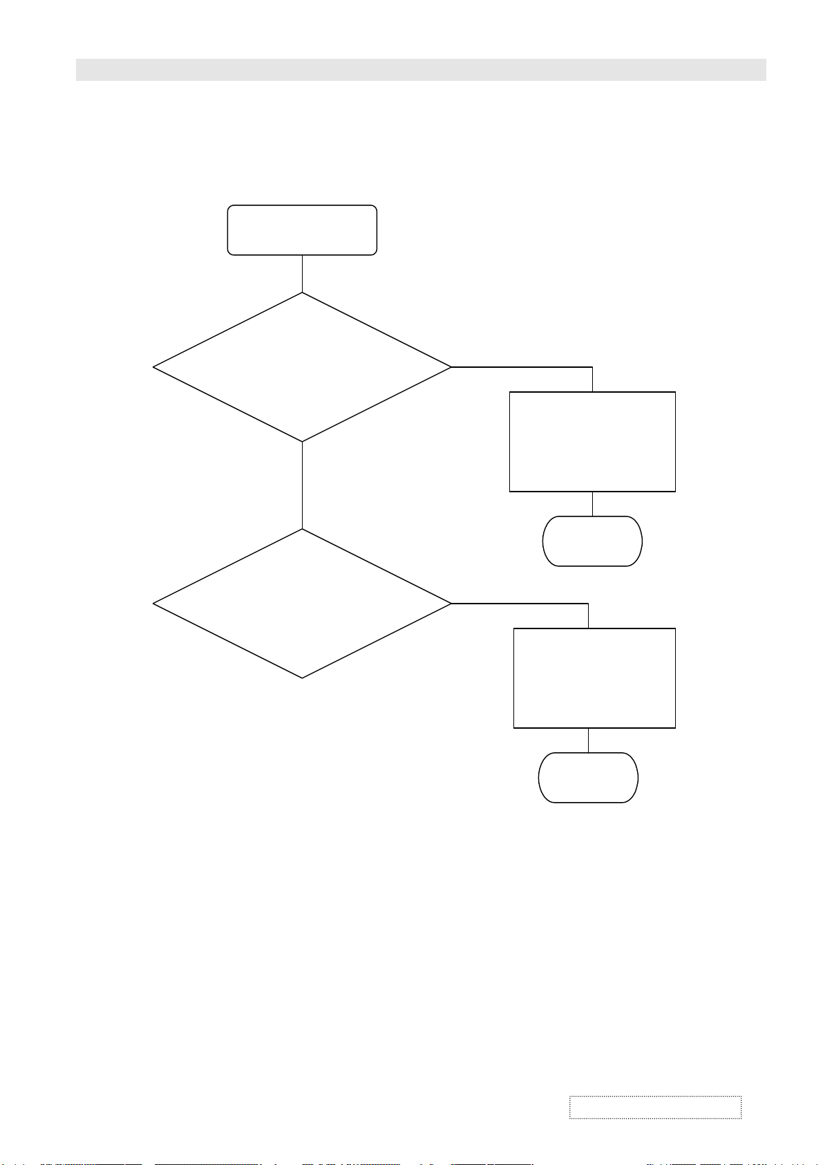
TROUBLE SHOOTING GUIDES VER1.0
No Power
SET POWER ON
Panel Main Power
Check
G
Panel SUB Power
Check
NG
Replace Main Power
Check
OK
NG
Replace SUB Power
Check
OK
ViewSonic Corporation
Confidential – Do Not Copy
5-1
Page 25

TROUBLE SHOOTING GUIDES VER1.0
No Picture
No picture
AV Module Board
(with Tuner)
(DPWB11410-1G---)
Check
G
Image Board
(DPWB11400-1G---)
Check
G
NG
Replace
AV Module Board
(
DPWB11410-1G---) Check
NG
Replace Image Board
(DPWB11400-1G---)
Check
(with Tuner)
OK
OK
PDP Panel Module
(P50WXDP1)
Check
NG
Replace
PDP Panel Module
(P50WXDP1)
Check
OK
ViewSonic Corporation
Confidential – Do Not Copy
5-2
Page 26

TROUBLE SHOOTING GUIDES VER1.0
Vertical Line Fail
Vertical Line
Fail
X-TOP
X-BOTTOM
Check
G
PDP Panel Module
Assembly
(P50WXDP1)
NG
Replace
X-TOP
X- BOTTOM
Check
OK
NG
Replace
PDP Panel Module Assembly
(P50WXDP1)
Check
ViewSonic Corporation
OK
Confidential – Do Not Copy
5-3
Page 27

TROUBLE SHOOTING GUIDES VER1.0
(
Horizontal Line Fail
Horizontal Line
Fail
Z-SUS
(6870QZC001)
Check
G
Y-SUS(6870QYC001)
Check
Y-DRV-TOP
(6870QDC001) Check
Y-DRV-BOTTOM
(6870QFC001) Check
G
NG
Replace
Z-SUS
(6870QZC001) Check
OK
NG
Replace
Y-SUS(6870QYC001) Check
Y-DRV-TOP
(6870QDC001) Check
Y-DRV-BOTTOM
6870QFC001) Check
ViewSonic Corporation
PDP Panel Module
Assembly
(P50WXDP1)
Check
5-4
NG
OK
Replace
PDP Panel Assembly
(P50WXDP1)
Check
OK
Confidential – Do Not Copy
Page 28

TROUBLE SHOOTING GUIDES VER1.0
No Remote Control
SET POWER ON
Remote Control
Check
G
Front Button Control
Board
(DPWB11372-1G-KS)
Check
G
NG
Replace
Battery
NG
Replace
(BRC-241) Check
OK
Replace Front Button
Control Board
(DPWB11372-1G-KS)
Check
OK
ViewSonic Corporation
Image Board
(DPWB11400-1G---)
Check
OK
NG
Replace Image Board
(DPWB11400-1G---)
Check
O K
Confidential – Do Not Copy
5-5
Page 29
TROUBLE SHOOTING GUIDES VER1.0
Front Button Fail
SET POWER ON
Front Button Control
Board
DPWB11372-1G-KS
NG
Check
Image Board
DPWB11400-1G---
Check
G
NG
Replace Front Button
Control Board
DPWB11372-1G-KS
Check
OK
Replace
Image Board
DPWB11400-1G---
Check
ViewSonic Corporation
OK
Confidential – Do Not Copy
5-6
Page 30

SCHEMATIC DIAGRAM
Panel
S
L
SB5V_CPU
R5
10K
1/16W
SB5V_CPU
SB5V
C426
+
1uF
50V
D
SCRAT_S O
SCART _SIP[ 18]
TELEXONP[18]
S_DETP[18]
AVB_DETnP[18]
TUN_DETnP[ 18]
U68
L1
SB5V
C1
0. 1 uF
25V
Z
D1
RLS4148
U5
S80845ANU P
V
I
N
+C4
10uF
16V
D
INT_RTCP[2]
INT_DPTV_SP[14]
INT_DPTVP[13]
INT _USBP[2]
TXDP[2]
RXDP[ 2 ]
C6
10PF
T
50V
D
U68
AMC7630-5
1
VIN
VOUT
2
GND
GND
3
GND
GND
4 5
EN GND
R412
10K
1/16W
R411
10K
1/16W
D
NOTE:
SD, D_CTL, RESETQ
ARE USED IN
PAL TUNER SYSTEM
R46 0 1/16W
R50 0 1/16W
R51 0 1/16W
R294 0 1/ 16W
AVB_DETn
TUN_DETn
TP16
SB5V_IO
TDO
TMS
GND
28
4 5
TDI
TMS
TCK
I/O16
TCK
I/O17
I/O18
I/O19
I/O20
I/O21
I/O22
I/O23I/O12
I/O24
I/O25
I/O26
I/O27
I/O28
I/O29
I/O30
I/O31
I/O0
I/O01
I/O02
GND
39
RP3
10K ohm
RP46
N/10K ohm
TP17
TP18
TP19
TP20
TP21
TP26
TP27
SB5V_CPU
TDO P[18]
TDI P[18]
TMS P[18]
TCK P[18]
18
19
20
21
22
23
24
2512
30
31
32
33
34
35
36
37
40
41
42
18
27
36
45
GIHS P[ 7]
GIVS P[ 7]
J5
VCNC P0316-EJST-
R36 10K 1/ 16W
R37 10K 1/ 16W
R39 10K 1/ 16W
U6C
L1
N/0
1/8W
P5
P6
P3
P0
P4
P2
P1
PA2/TIOCA0/TCLKC
PA3/TIOCB0/TCLKD
PA4/T I OCA1/A23
PA5/T I OCB1/A22
PA6/T I OCA2/A21
PA7/T I OCB2/A20
RP5
10K ohm
1 8
2 7
3 6
4 5
U6E
74LVT04
P7
20
D7
A0
A1
A2
A3
A4
A5
A6
A7
A8
A9
A10
A11
A12
A13
A14
A15
A16
A17
A18
A19
PA0/T CLKA
PA1/T CLKB
PB0/TIOCA3
PB1/TIOCB3
PB2/TIOCA4
PB3/TIOCB4
PB4/T O CXA4
PB5/T O CXB4
PB6
PB7/ADT RG
P70/AN0
P71/AN1
P72/AN2
P73/AN3
P74/AN4
P75/AN5
P76/AN6
P77/AN7
YUV_SW P[11,18]
15Kn_MP P[ 11,12, 18]
15Kn_SP P[ 18]
A_MUTEn P[ 18]
YUVn_RGB P[9,18]
RSTnC711 P[ 5, 8]
A0
A1
A2
A3
A4
A5
A6
A7
A8
22
23
24
25
26
27
28
29
31
32
33
34
35
36
37
38
39
40
41
42
73
74
75
76
77
78
79
80
1
2
3
4
5
6
7
8
59
60
61
62
63
64
65
66
A9
A0
A10
A1
A2
A11
A3
A12
A4
A13
A14
A5
A6
A15
A7
A16
A17
A8
A9
A10
A11
A12
A13
A14
A15
A16
A17
A18
A19
R31 33 1/ 16W
R33 33 1/ 16W
GIVS
R10 33 1/ 16W
R12 33 1/ 16W
REMOT E
GIHS
R18 33 1/16W
R21 33 1/16W
R24 33 1/16W
KEYPAD_IN
SO
AFT_TUN
R4 N/0 1/ 16W
R41 N/ 0 1/ 16W
HS_POL
VS_POL
SOGn
(NO)
R345
0
1/16W
R226
0
1/16W
D
RP42
N/10K ohm
TP1
TP2 TP15
TP3
TP6
TP9
TP10
TP11
TP12
RP48
N/10K ohm
SB5V_IO
TP5
SB5V_M
SB5V_IO
TP4
NMI
R13
47
1/16W
C12
0. 1 uF
25V
Z
D
182736
R11
N/47
C23
0. 1 uF
25V
Z
D
U4
HD6413079F
MPU
45
MD1
44
MD0
51
EXTAL
52
XTAL
46
@
47
STBY
48
RES
57
RESO
49
NMI
54
AS
55
RD
56
WR
69
P80/IRQ0
70
P81/IRQ1
71
P82/IRQ2
72
P83/IRQ3
9
P90/T XD
10
P92/RXD
11
P94/SCK/ IRQ4
43
P60/WAIT
21
VCC
68
AVCC
53
VCC
12
VSS
58
AVSS
50
VSS
30
VSS
D
67
VREF
C418
+
10uF
16V
D
ST ANDBY
POWER_ON
RESE T
45
RP9
10K ohm
C244
0. 1 uF
25V
Z
D
SDA_1
SCL_1
ADDR1
11 10
13141516171819
D0D1D2D3D4D5D6
SB5V_IO
R1
10K
1/16W
D
SB5V_CPU
R6
100K
1/16W
V
12
O
U
TGND
J2
C5
Z
25V
R16
3.3K
1/16W
SB5V_CPU
+
D
RP8
18
27
36
45
C428
4. 7 uF
16V
N/CO N3
RP44
10K ohm
1 8
2 7
182736
1
2
NMI
3
TP7
TP8
R17
3.3K
1/16W
SB5V
AC_DET P[18]
SB5V_IO
3 6
4 5
45
R44
10K
1/16W
IO_INTn
ADDR1
R45
0
1/16W
3
0. 1 uF
C7
10PF
T
50V
D
8
7
6
RP7
10K ohm
10K ohm
R349
N/ 1M
1/16W
Y1
16MHz
C2
T
T
33PF
50V
D
D
SB5V_CPU
R7 3. 3K 1/16W
R8 47 1/16W
R9
47
1/16W
R14
N/3.3K
C8
0. 1 uF
25VZ
D
SB5V_CPU
SB5V_M
C24
0. 1 uF
25V
Z
D
L3
SB5V
0
1/8W
U8
PCA9555D B
1
VDD
INT
2
A1
SDA
3
A2
SCL
4
P00
A0
5
P01
P17
6
P02
P16
7
P03
P15
8
P04
P14
9
P05
P13
10
P06
P12
11
P07
P11
12 13
VSS P10
D
C3
33PF
50V
INT_RTC
INT_DPTV_S
INT_DPTV
INT _USB
R15
3.3K
1/16W
+C9
10uF
16V
D
C25
0. 1 uF
25V
Z
24
R38 10 1/ 16W
23
R40 10 1/ 16W
22
21
20
19
18
17
16
15
14
5 6
12
11
10
9
8
7
6
5
27
26
23
25
4
28
29
3
2
30
16
1 8
2 7
R132
0
1/16W
74LVT04
U3
29C020CP90BS
A0
D0
A1
D1
A2
D2
A3
D3
A4
D4
A5
D5
A6
D6
A7
D7
A8
A9
A10
A11
VCC
A12
VPP
A13
A14
PGM
A15
A16
A17
OE
CE
GND
SB5V_CPU
RP1
10K ohm
3 6
4 5
R19 33 1/16W
R20 33 1/16W
SO P[2,5]
AFT_TUN P[18]
D_ CL T
SOGn P[ 9]
SB5V_IO
1 8
2 7
3 6
4 5
182736
45
U6D
74LVT04
9 8
13
14
15
17
18
19
20
21
CPU 5 V
32
A18
1
31
24
22
SCART_RGB P[18]
R42
N/ 10K
1/16W
U9
N/PCA9555DB
IO_INTn
1
ADDR2
2
3
4
5
6
7
8
9
10
11
12 13
D
VDD
INT
A1
A2
P00
P01
P02
P03
P04
P05
P06
P07
VSS P10
P0
P1
P2
P3
P4
P5
P6
P7
CPU 5 V
RP2
10K ohm
1 8
2 7
3 6
4 5
SCL1
SDA1
SB5V_CPU
R29
5.6K
1/16W
D
24
R43 N/10 1/16W
23
SDA
R52 N/10 1/16W
22
SCL
21
A0
20
P17
19
P16
18
P15
17
P14
16
P13
15
P12
14
P11
L8
0
1/8W
Q4
2SC2412KBQ
SB5V_IO
D
+
D
A0
A1
A2
A3
A17
A18
A19
SCLK
SB5V_CPU
R25
5.6K
1/16W
Q1
2SC2412KBQ
C243
N/10uF
16V
182736
45
U1
A5-32-10VC4
P0
R342
0
1/16W
SB5V_CPU
C14
+
10uF
16V
D
C15
+
10uF
16V
D
C242
N/0.1uF
25V
Z
D
RP47
N/10K ohm
1
I/O5
2
I/O6
3
I/O7
8
I/O8
9
I/O9
10
I/O10
11
I/O11
13
I/O13
14
I/O14
15
I/O15
5
CLK0
27
CLK1
16
VCC
38
VCC
43
I/O03
44
I/O04
SCL2
SCS
SI
PLLDATA
PLLCLK
HSYNC_MP
HSYNC_SP
SDA2
SCL0
SDA0
SDA_1
SCL_1
ADDR2
D
D
R30
22K
1/16W
R35
22K
1/16W
29
6
SB5V_CPU
R27
22K
1/16W
R34
22K
1/16W
1 8
2 7
SB5V_IO
4726
TD1
TDO
GND
GND
17
3 6
6
5
4
3
2
1
R2
N/1.5K
1/16W
LD001
N/ LED
SCL2
SDA2
R70
0
1/16W
SB5V
GND
SB_LED
ON_LED
SW _IN
RC_I N
R344
0
1/16W
SB5V_CPU
SB5V
R3
N/1.5K
1/16W
LD002
N/ LED
RGBn_DVI P[ 3,10,18]
OCKINV P[8]
SB P[18]
FRE EZE P[5]
USB_CS P[ 2]
PNL_CTLn P[4]
PS_DPTV P[13]
Y UV_SPSW P[11, 18]
LG_VS
RST_DPT V P[ 13,14, 18]
AO_SEL P[ 18]
SURR1 P[18]
SURR2 P[18]
REAE TQ
SPK_CTL P[ 18]
ALE_DPTV P[13]
WRn_DPT V P[ 13]
RDn_DPT V P[ 13]
SCL2 P[2, 7,10,12,13,14,18]
SCLK P[2, 5]
SCS P[5]
SI P[2,5]
PLLDATA P[ 3]
PLLCLK P[ 3]
HSYNC_MP P[ 11]
HSYNC_SP P[11]
SDA2 P[2,7,10, 12, 13,14, 18]
SCL0
SDA0
J3
N/CO N4
1
2
3
4
D
SB5V
+ C13
D
C16
1000PF
50V
P[0..7]
A[ 0. . 19]
SO1
N/W27C010 _5
EEPROM(DIP32)
A0
12
A0
A1
11
A1
A2
10
A2
A3
9
A3
8
A4
A4
7
A5
A5
A6
6
A6
A7
5
A7
A8
27
A8
A9
26
A9
A10
23
A10
A11
25
A11
A12
4
A12
28
A13
A13
29
A14
A14
A15
3
A15
A16
2
A16
A17
30
A17
24
OE
CEn
22
CE
PLLCLK
PLLDATA
D
U6A
RGBn_DVI
10uF
16V
Q2
2SC2412KBQ
C17
1000PF
50V
D
74LVT04
1 2
U6F
74LVT04
13 12
SB5V
C10
10uF
16V
SCL0
SDA0
SB5V
Q3
2SC2412KBQ
C19
C18
1000PF
1000PF
50V
50V
Title
DIG I T A L SY ST EM - CPU H8/ 3 0 05 & F L A S H ME MO RY & CP L D & I / O
Siz e Doc um ent Nu m ber
QPWB1140 0-1G---
C
Wednesday, Oc t ober 30, 2002
Dat e:
VER1.0
P[0..7] P[13]
J4
N/CO N3
1
2
3
+
C11
0. 1 uF
25V
Z
D
D
R22
10
1/16W
R23
10
1/16W
R28
47K
1/16W
R32
47K
1/16W
C20
120PF
T
50V
13
Q0
14
O1
15
O2
17
O3
18
O4
19
O5
20
O6
21
O7
32
VCC
1
VPP
31
PGM
16
GND
SB5V_M
3 4
D
F1
0
1/8W
P0
P1
P2
P3
P4
P5
P6
P7
SB5V_M
A18
PGMn
D
U6B
74LVT04
1
2
3
4 5
U7
M24C16WBN6
8
VCC
7
TEST
6
SCL
F2
0
1/8W
F3
0
1/8W
F4
0
1/8W
Sheet
U3 SOCKE T
I1514-132-S
1
2
3
4
5
6
7
8
9
10
11
12
13
14
15
16
SB5V
L2
0
1/8W
U7 So c ket
I1177-108--
8
7
6
A0
A1
A2
VSSSDA
POWER_ON
ST ANDBY
KEYPAD_IN
REMOT E
C375
120PF
T
50V
D
118
PD_DVIn P[8]
PD_9884n P[7]
1
2
3
45
of
32
31
30
29
28
27
26
25
24
23
22
21
20
19
18
17
Rev
1.4
ViewSonic Corporation
6-1
Confidential – Do Not Copy
Page 31

SCHEMATIC DIAGRAM
R59
47
1/16W
R60
47
1/16W
R61
47
1/16W
R63
47
1/16W
R64
N/220
1/16W
C33
0.1uF
25V
Z
5V_OSD
T
D
R55
N/1K
1/16W
C250
N/27PF
50V
V33SB
+
R56
N/1K
1/16W
C254
27PF
T
50V
D
L6
0
1/8W
C37
47uF
16V
R57
N/1K
1/16W
C255
N/27PF
T
50V
D
C38
0.1uF
25V
Z
R58
1K
1/16W
INTENSITY
C39
0.1uF
25V
Z
C30
100PF
T
50V
D
C31
1uF
50V
C34
1uF
50V
C40
0.1uF
25V
Z
C252
27PF
T
50V
R_OSD P[5]
G_OSD P[5]
B_OSD P[5]
DTEN P[5]
TP21
1
+
3
4
+
5
16
2
6
15
D
R66
100
1/16W
U12
HIN232CB
C1+
C1C2+
C2VCC
V+
VGND
R1-OUT
T1-OUT
T2-OUT
R2-OUT
POCLKOSDP[3]
D
5V_OSD
HSYNCORP[5]
SDA2P[1,7,10,12,13,14,18]
SCL2P[1,7,10,12,13,14,18]
+
SDA2
SCL2
C27
10uF
16V
R62
62
1/16W
R227
N/100
1/16W
R54
0
1/16W
C28
0.1uF
25V
Z
R65
100
1/16W
R67
100
1/16W
C416
N/22PF
T
50V
D
D
C29
120PF
50V
1
2
3
4
5
6
7
8
U11
MTV130
VSS
XIN
NC
VDD
HFLB
SSB
SDA
SCK
VSS
R-OUT
G-OUT
B-OUT
FBKG
INT
VFLB
VDD
16
15
14
13
12
11
10
9
P5V
5V_OSD
C32
+
N/10uF
16V
L4
0
1/8W
D
D
D
L5
N/0
1/8W
T1-IN
R1-IN
R2-IN
T2-IN
A5V
SDA2_33P[4,7,13]
SCL2_33P[4,7,13]
VSYNCO P[4,5]
TXD
11
RXD
12
13
14
TP22
7
8
TP23
TP24
9
10
TP25
R68
33
1/16W
R69
33
1/16W
SDA2_33
SCL2_33
SB5V
TXD P[1]
RXD P[1]
SD
RD
C35
180PF
T
50V
D
4 5
3 6
2 7
1 8
RP12
10K ohm
C36
180PF
T
50V
D
DTR
CTS
RTS
DSR
V33
SDA2
SCL2
V33
1
Q5
BSN20
3
5
9
4
D
8
3
7
2
6
1
Title
Size Document Number
B
Date: Sheet
2
P1
QSOCD1553-109--
10
11
DI GI TAL SY STEM - OSD-MTV030 / USB C Y7C 63723 / RS232 H I N 232C B
QPWB11400-1G---
Wednes day , Oct ober 30, 2002
VER1.0
V33
3
SDA2_33
1
Q6
BSN20
2
SCL2_33
D(2)
M8p
S(3)
G(1)
BSN20
218
of
Rev
1.4
ViewSonic Corporation
6-2
Confidential – Do Not Copy
Page 32

SCHEMATIC DIAGRAM
D
C57
0.1uF
25V
Z
2
3
5
6
11
10
14
13
1
15
U15
74LVC157
1A
1B
2A
2B
3A
3B
4A
4B
A/B
G
D
1Y
2Y
3Y
4Y
VCC
GND
6
7
13
3
5
1
2
4
4
7
9
12
16
8
U16
ICS9161A
X1
X2
VDD
AVDD
GND
SEL0_CLK
SEL1_DATA
OE
R77
33
1/16W
R79
56
1/16W
C50
0.1uF
25V
Z
D
MCLK
VCLK
ERROUT
INIT0
INIT1
EXTCLK
EXTSEL
PD
V33SB
8
9
10
12
14
11
15
16
VCLK
26M
67.425M
34.234
TP28
VCCPLL
C5:F8:47
8C:FC:46
AC:AC:47
R80
33
1/16W
R81
47
1/16W
R83
150
1/16W
POCLK
S-PDP 42
S-PDP 50
L-PDP 42
L-PDP 50
T
D
C49
47PF
50V
T
D
C53
N/18PF
50V
T
D
MCLKREGISTER
80M
90M
100M
R78
33
1/16W
C54
68PF
50V
A/B
0
1
CLK
POCLK
REGISTER
1B:38:71
21:AC:71
22:EC:71
PIHS P[5]
DDCVSY NC P[7]
PIVS P[5]
PICLK P[5]
PIHSS P[7]
Y
DVI-H,V,CLK
RGB-H,V,CLK
CLK P[5,6]
POCLK P[4,5]
POCLKOSD P[2]
Title
Size Document Number
Date: Sheet
DIGI TAL SYSTEM - HSYN SW & CLOC K GEN.
QPWB11400-1G---
B
Friday, F ebruary 21, 2003
DVI_HSP[8]
PLLHSOP[7]
DVI_VSP[8]
FGVSP[7,8,9]
DVI_PICKP[5]
DATACKP[7]
FGVS
R386
150
1/16W
FGHSP[7,9]
RGBn_DVIP[1,10,18]
FGHS
T
D
C404
33PF
50V
FROM CPU
VCCPLL
T
C51
12PF
50V
Y3
14.318MHz
D
R350
N/1M
1/16W
C52
12PF
T
50V
D
V33
L13
0
1/8W
+
D
C55
47uF
16V
C56
0.1uF
25V
Z
D
R82
4.7
1/16W
D
PLLCLKP[1]
PLLDATAP[1]
VER1.0
Rev
1.4
318
of
ViewSonic Corporation
6-3
Confidential – Do Not Copy
Page 33

SCHEMATIC DIAGRAM
AVCC
TX2-
TX0-
TX1-
TX0+
TX1+
AVCC
AGND
IDCK-
IDCK+D5D4D3D2D1D0
C438
0.1uF
16V
Z
TXC+
AVCC
D10D9D8D7D6
R441
0
1/16W
C437
0.1uF
16V
Z
Note: All polarized
CAPs should
be Tantalum
For T MDS
TXC-
AGND
C444
0.1uF
16V
Z
TX2+
TX2TX1+
TX1TX0+
TX0TXC+
TXC-
171819202122232425262728293031
PGND
PVCC 1
EXT_SWING
BSEL/SCL
DSEL/ SDA
ISEL/ RST
EDGE/HT PLG
CT L1/ A1/DK1
CT L2/ A2/DK2
CT L3/ A3/DK3
GND
64
R348
510
1/16W
MSEN
VSYNC
HSYNC
VREF
L52
200+ Ohm
GND
VCC
PD
DE
VCC
TMDS33
PGND
16
15
14
13
12
11
10
R347 0 1/16W
9
8
7
6
R433 100 1/16W
5
R443 100 1/16W
4
3
R442 100 1/16W
2
1
U69
SiI164
T MDS I NT E RF A C E
L53
n/0
AVCC
R439
N/0
SC2_ 33
SD2_ 33
PVCC
C433
+
10uF
16V
PGND
PVCC
C439
C448
0.1uF
+
10uF
16V
16V
Z
1/16W
R440
N/0
1/16W
C442
0.1uF
25V
Z
SC2_ 33
SD2_ 33
TMDS33
PNLC TL33
DSVSYNC0
DSHSY NC0
DBLANKN
TMDS33
TXCTXC+
TX0TX0+
TX1TX1+
TX2TX2+
Connect to TMDS
PDP Module
C441
C440
0.1uF
0.1uF
16V
16V
Z
Z
Title
DIG I T AL SY ST EM - BUFFER 74LVT 244 & LVDS / T MDS & PANEL CONN.
Size Docum ent Num ber
QPWB11 40 0-1G---
C
Dat e:
Friday, F ebruary 21, 2003
VCCB F
VCCB F
R382
68
1/16W
R86
N/22 1/16W
BVSYNCO
BHSYNCO
BBLANKN
TP108
BROUT0
BROUT1
BROUT2
BROUT3
BROUT5
BROUT6
BROUT7
BGOUT0
BGOUT1
BGOUT2
BGOUT3
BGOUT4
BGOUT5
BGOUT6
BGOUT7
BBOUT0
BBOUT1
BBOUT2
BBOUT3
BBOUT4
BBOUT5
BBOUT6
BBOUT7
PCLK_LG
PCLK_SST
RP36
22 o hm
1 8
2 7
3 6
4 5
1 8
2 7
3 6
4 5
RP37
22 o hm
RP38
22 o hm
1 8
2 7
3 6
4 5
1 8
2 7
3 6
4 5
RP49
22 o hm
RP40
22 o hm
1 8
2 7
3 6
4 5
1 8
2 7
3 6
4 5
RP41
22 o hm
1 8
2 7
3 6
4 5
C351
N/47p
C359
N/47p
C367
N/47p
RP35
22 o hm
C352
N/47p
C360
N/47p
C368
N/47p
C353
N/47p
C361
N/47p
C369
N/47p
DSVSY NCO
DSHSY NCO
DBLANKN
C354
N/47p
C362
N/47p
C370
N/47p
C355
N/47p
C363
N/47p
C371
N/47p
C356
N/47p
C364
N/47p
C372
N/47p
C357
N/47p
C365
N/47p
C373
N/47p
C358
N/47p
C366
N/47p
C374
N/47p
BRROUT0
BRROUT1
BRROUT2
BRROUT3
BRROUT4
BRROUT5
BRROUT6
BRROUT7
BRGOUT0
BRGOUT1
BRGOUT2
BRGOUT3
BRGOUT4
BRGOUT5
BRGOUT6
BRGOUT7
BRBOUT0
BRBOUT1
BRBOUT2
BRBOUT3
BRBOUT4
BRBOUT5
BRBOUT6
BRBOUT7
R436
0
1/16W
R430
0
1/16W
N/10K
1/16W
TMDS33
R429
R435
PVCC
PGND
N/10K
1/16W
TMDS33
33
34
35
BRROUT7
36
BRROUT6
37
BRROUT5
38
BRROUT4
39
BRROUT3
40
BRROUT2
41
BRROUT1
42
43
BRROUT0
BRGOUT7
44
BRGOUT6
45
BRGOUT5
46
BRGOUT4
47
48
C443
C434
0.1uF
+
10uF
25V
16V
Z
32
TX2+
AGND
VCC
RESERVED
DKEN
D23
D22
D21
D20
D19
D18
D17
D16
D15
D14
D13
D12
GND
PVCC 2
D11
495051525354555657585960616263
BRGOUT3
BRGOUT2
BRGOUT1
BRGOUT0
BRBOUT7
BRBOUT6
PCLK_LG
BRBOUT5
BRBOUT4
BRBOUT3
BRBOUT2
BRBOUT1
BRBOUT0
POCLKP[3,5]
VSYNCOP[2, 5]
HSY NCOP[ 5]
BLANKnP[5]
PNL_C TLnP[ 1]
POCLK
VSYNCO
HSY NCO
BLANKn
TP109
PNL_C TLn
TP29
TP30
R130
N
TP31
ROUT[0.. 7]P[5]
ROUT[0.. 7]
PNL_C TLn
ROUT 7
ROUT 5
ROUT 3
ROUT 1
ROUT 0
ROUT 2
ROUT 4
ROUT 6
GOUT[0..7]P[5]
GOUT[0..7]
PNL_C TLn
GOUT 7
GOUT 5
GOUT 3
GOUT 1
GOUT 0
GOUT 2
GOUT 4
GOUT 6
BOUT[0..7]P[5]
BOUT[0..7]
PNL_C TLn
BOUT7
BOUT5
BOUT3
BOUT1
BOUT0
BOUT2
BOUT4
BOUT6
2
4
6
8
11
13
15
17
1
19
2
4
6
8
11
13
15
17
1
19
2
4
6
8
11
13
15
17
1
19
2
4
6
8
11
13
15
17
1
19
U18
74LV C244A BD
1A1
1A2
1A3
1A4
2A1
2A2
2A3
2A4
1G
2G
U19
74LV C244A BD
1A1
1A2
1A3
1A4
2A1
2A2
2A3
2A4
1G
2G
U20
74LV C244A BD
1A1
1A2
1A3
1A4
2A1
2A2
2A3
2A4
1G
2G
U21
74LV C244A BD
1A1
1A2
1A3
1A4
2A1
2A2
2A3
2A4
1G
2G
18
1Y1
1Y2
1Y3
1Y4
2Y1
2Y2
2Y3
2Y4
VCC
GND
1Y1
1Y2
1Y3
1Y4
2Y1
2Y2
2Y3
2Y4
VCC
GND
1Y1
1Y2
1Y3
1Y4
2Y1
2Y2
2Y3
2Y4
VCC
GND
1Y1
1Y2
1Y3
1Y4
2Y1
2Y2
2Y3
2Y4
VCC
GND
BPCLKO
TP32
16
14
TP33
12
9
TP34
7
5
R131
3
N
20
10
D
18
BROUT7
BROUT5
16
BROUT3
14
12
BROUT1
9
BROUT0
7
BROUT2 BROUT4
5
BROUT4
BROUT6
3
20
VCCB F
10
D
18
BGOUT7
BGOUT5
16
BGOUT3
14
BGOUT1
12
BGOUT0
9
7
BGOUT2
BGOUT4
5
BGOUT6
3
20
VCCB F
10
D
18
BBOUT7
BBOUT5
16
14
BBOUT3
12
BBOUT1
BBOUT0
9
BBOUT2
7
5
BBOUT4
3
BBOUT6
20
10
D
LVDS33
LVDS33
BRROUT6
BRROUT7
BRROUT0
BRROUT1
BRROUT2
BRROUT3
BRROUT4
BRROUT5
BRGOUT6
BRGOUT7
BRGOUT0
BRGOUT1
BRGOUT2
BRGOUT3
BRGOUT4
BRGOUT5
BRBOUT6
BRBOUT7
BRBOUT0
BRBOUT1
BRBOUT2
BRBOUT3
BRBOUT4
BRBOUT5
C396
+C401
N/0.1uF
N/10uF
Z
25V
+C400
C397
N/10uF
N/0.1uF
Z
25V
R391
0
1/16W
50
TxIN27
TxIN5
TxIN0
TxIN1
TxIN2
TxIN3
TxIN4
TxIN6
TxIN10
TxIN11
TXIN7
TxIN8
TxIN9
TxIN12
TxIN13
TxIN14
TxIN16
TxIN17
TxIN15
TxIN18
TxIN19
TxIN20
TxIN21
TxIN22
TxIN23
R-F B
513212933
51
52
54
55
56
10
11
12
14
16
18
15
19
20
22
23
24
25
R393
0
1/16W
2
3
8
4
6
7
For SAMSUNG LVDS PDP
GND
R390
N/0
1/16W
GND
R402
0
1/16W
R408
0
1/16W
R392
32
LVDS VCC
TxCLKOUT -
TxCLKOUT +
TxIN24
TxIN25
PW R DWN
TxIN26
TxCLK IN
TxOUT0-
TxOUT0+
TxOUT1-
TxOUT1+
TxOUT2-
TxOUT2+
TxOUT3-
TxOUT3+
0
1/16W
27
28
30
31
48
47
46
45
42
41
40
39
38
37
U66
N/DS90CF 385A
DSHSY NC0
DSVSYNC0
SC2
LVDS33
1
917264434
VCC
VCC
VCC
PLL VCC
GND
GND
PLL GND
PLL GND
LVDS GND
LVDS GND
353643
LVDS GND
49
GND
53
VCCB F
L50
N/BLM31A 601S
U24F
74LVT 04
PNLC TL33
R432
0
1/16W
RXIN0RXIN0+
RXIN1RXIN1+
RXIN2RXIN2+
RXCLKINRX CLKI N+
RXIN3RXIN3+
DBLANKN
R73
N/0
1312
1 2
3 4
5 6
7 8
9 10
11 12
13 14
15 16
17 18
19 20
21 22
23 24
25 26
27 28
29 30
31 32
33 34
35 36
37 38
39 40
J1
N/CON31
ViewSonic Corporation
LVDS33
+C399
N/10uF
16V
PNL_C TLn
L51
200+ Ohm
V33P
C395
C394
C390
N/0.1uF
N/0.1uF
Z
25V
PCLK_LG
C422
T
22PF
50V
Z
Z
25V
N/0.1uF
25V
V33P
C398
N/0.1uF
25VZ
L17
N/0
1/ 8W
P5V
L14
+C59
0
1/ 8W
C60
47uF
0.1uF
16V
25V
Z
D
C435
C446
0.1uF
+
10uF
25V
16V
Z
VCCB F
C62
C61
0.1uF
0.1uF
25V
25V
Z
Z
For SS TTL
Resistors
R86
IC
SD2
R84
N/0
Inductances
Connectors
J18,J19
L14
Capacitors
6-4
TMDS33
C436
C447
0.1uF
+
10uF
16V
16V
Z
L54
0
1/ 8W
PGND
C63
0.1uF
25V
Z
For SS LVDS
R382,R390,
R391,R392,
R393
U66
J1
L17,L50
C390,C394,
C395,C396,
C397,C398,
C399,C400,
C401
Confidential – Do Not Copy
VER1.0
SCL2_ 33
SCL2_ 33 P[2,7,13]
SDA2_ 33
SDA2_ 33 P[2, 7,13]
R428 10K 1/16W
R427 N/10K 1/16W
R426 N/10K 1/16W
R425 5.6K 1/16W
R424 10K 1/16W
R423 10K 1/16W
R422 10K 1/16W
R421 N/10K 1/16W
R420 N/0 1/16W
R419 0 1/16W
R418 0 1/16W
R416 N/0 1/16W
R415 N/0 1/16W
R414 N/0 1/16W
R413 0 1/16W
R434
2.2K
1/16W
R346
N/0
1/16W
1 2
3 4
5 6
7 8
9 10
11 12
13 14
15 16
17 18
19 20
21 22
23 24
25 26
27 28
29 30
31 32
33 34
35 36
37 38
39 40
J18
CON40
TMDS33
Shee t
TMDS33
Rev
1.4
of
418
Page 34

SCHEMATIC DIAGRAM
J8
N/CON6
1
2
3
4
5
6
PCn_MPU
D
N/HE ADER 1X2
PCn_MPUP[18]
PCSCSP[18]
PCSIP[18]
PCSCL KP[18]
SSOP[18]
PCSI
SI
SIP[1,2]
PCSCS
SCS
SCSP[1]
SSO
PCSCL K
SCLK
SCLKP[1,2]
PCn_MPU
R89
10K
1 2
D
PCn_MPU
PCSCS
PCSI
PCSCL K
SSO
1/16W
V33
JP3
PID[ 0.. 7]P[7,8]
PID[8..15]P[7,8]
PID[16..23]P[7,8]
PID[24..31]P[7,8]
PID[32..39]P[7,8]
PID[40..47]P[7,8]
PICLKP[3]
PIVSP[3]
PIHSP[3]
FREEZ EP[ 1]
DVI _CLKP[8]
VIP711
+C65
VIP711
C66
22uF
16V
0.1uF
25V
Z
VIP711
+C71
VIP711
+C72
22uF
16V
22uF
16V
PID[8..15]
PID[16..23]
PID[24..31]
PID[32..39]
PID[40..47]
C67
0.1uF
25V
Z
+C73
22uF
16V
D
PID[ 0.. 7]
2
3
5
6
11
10
14
13
1
15
DVI _CLK
U22
74LVC 157
1A
1B
2A
2B
3A
3B
4A
4B
A/B
G
C68
0.1uF
25V
Z
C74
0.1uF
25V
Z
GND
4
PID0
PID1
PID2
PID3
PID4
PID5
PID6
PID7
PID8
PID9
PID10
PID11
PID12
PID13
PID14
PID15
PID16
PID17
PID18
PID19
PID20
PID21
PID22
PID23
PID24
PID25
PID26
PID27
PID28
PID29
PID30
PID31
PID32
PID33
PID34
PID35
PID36
PID37
PID38
PID39
PID40
PID41
PID42
PID43
PID44
PID45
PID46
PID47
D
C69
0.1uF
25V
Z
SSI
7
SSCS
9
SO
SO P[1,2]
12
SSCLK
16
8
MA_IP[ 0.. 13]P[6]
C75
0.1uF
25V
Z
V33P
TP91
V33
C64
0.1uF
25V
Z
D
190
PID0
191
PID1
192
PID2
193
PID3
194
PID4
195
PID5
196
PID6
197
PID7
198
PID8
199
PID9
201
PID10
203
PID11
204
PID12
205
PID13
206
PID14
207
PID15
208
PID16
209
PID17
210
PID18
211
PID19
214
PID20
215
PID21
216
PID22
217
PID23
218
PID24
219
PID25
220
PID26
221
PID27
222
PID28
223
PID29
225
PID30
226
PID31
227
PID32
228
PID33
229
PID34
230
PID35
231
PID36
232
PID37
233
PID38
234
PID39
235
PID40
238
PID41
239
PID42
240
PID43
241
PID44
242
PID45
243
PID46
244
PID47
248
PICLK
245
PIVS
246
PIHS
250
PIFLD
251
PIVSG O
VIP711
L15
0
1/8W
C76
0.1uF
25V
Z
D
VIP711
C77
0.1uF
25V
Z
MA_IP11
TP43
MA_IP13
TP44
MD_I P0
MD_I P2
MD_I P1
MA_I P1
MA_I P3
MA_I P0
MA_I P2
MA_IP12
MA_IP13
7675808182838687888990919293789101415161712
BA0
BA1
MA0
MA1
MA2
VDD
VDD
VDD
VDD
VDD
VDD
13192633404754606774859498
C78
0.1uF
25V
Z
MA_I P9
MA_I P7
MA_I P4
MA_I P6
MA_I P5
MA_I P8
MA_IP11
MA_IP10
MA3
MA4
MA5
MA6
MA7
MA8
MA9
MD0
MD1
MD2
MA10
MA11
VDD
VDD
VDD
VDD
VDD
VDD
VDD
VDD
VDD
VDD
VDD
VDD
VDD
113
121
128
134
141
147
C79
C80
0.1uF
0.1uF
25V
25V
Z
Z
MD_ IP33
MD_ IP15
MD_ IP14
MD_I P4
MD_ IP10
MD_I P5
MD_I P9
MD_I P6
MD_I P8
MD_I P3
MD_I P7
2021222324272829303134353637384142434445484950515355565758616263646668697071732787977349997
MD3
MD5
MD6
MD7
MD8
MD4
MD9
MD10
MD_ IP16
MD_ IP13
MD_ IP12
MD_ IP11
MD11
MD12
MD13
MD_ IP19
MD_ IP18
MD_ IP17
MD14
MD15
MD16
MD17
MD18
MD19
MD_ IP26
MD_ IP25
MD_ IP22
MD_ IP28
MD_ IP27
MD_ IP23
MD_ IP24
MD_ IP21
MD_ IP20
MD20
MD21
MD22
MD23
MD24
MD25
MD26
MD27
MD28
MD_ IP34
MD_ IP30
MD_ IP35
MD_ IP32
MD_ IP29
MD29
MD30
MD_ IP36
MD_ IP31
MD31
MD32
MD33
MD34
MD35
MD36
MD_ IP43
MD_ IP40
MD_ IP38
MD_ IP37
MD_ IP41
MD_ IP39
MD_ IP44
MD_ IP42
MD37
MD38
MD39
MD40
MD41
MD42
MD43
MD44
U23
IP00C713
VDD
VDD
VDD
VDD
VDD
VDD
VDD
VDD
VDD
VDD
VDD
VDD
AVDD
AGND
GND
GND
GND
GND
GND
GND
GND
GND
GND
GND
GND
GND
GND
GND
GND
GND
GND
GND
GND
GND
GND
GND
GND
GND
GND
GND
GND
GND
GND
154
161
168
175
182
188
202
213
237
249
256
1096108511182532394652596572849596
C81
C82
0.1uF
0.1uF
25V
25V
Z
Z
C83
0.1uF
25V
Z
C84
0.1uF
25V
Z
114
119
126
133
139
146
153
160
167
174
180
187
200
212
224
SSCS
SSI
VIP711
SSO
SCLKB
SSOP[18]
RSTnC711P[1,8]
C85
0.1uF
25V
Z
236
MD_ IP45
MD45
GND
MD_ IP46
MD46
GND
247
255
RP43
10K ohm
MD_IP[0.. 47] P[6]
CS n_I P P [ 6]
RASn_I P P[ 6]
CASn_I P P[ 6]
WRn_IP P[6]
LDQM P[6]
UDQM P[ 6]
MD_ IP47
CS
RAS
CAS
MWR
MD47
GND
D
DQM0
DQM1
MCL K SEL
SSSISO
SCLK
RST
253
2541252
100
18
27
36
45
CLK P [3, 6]
OSDDT0
OSDDT1
OSDDT2
OSDDT3
DVI _CLK
POD0
POD1
POD2
POD3
POD4
POD5
POD6
POD7
POD8
POD9
POD10
POD11
POD12
POD13
POD14
POD15
POD16
POD17
POD18
POD19
POD20
POD21
POD22
POD23
POD24
POD25
POD26
POD27
POD28
POD29
POD30
POD31
POD32
POD33
POD34
POD35
POD36
POD37
POD38
POD39
POD40
POD41
POD42
POD43
POD44
POD45
POD46
POD47
POCLK
POVS
POHS
POFLD
POEXT
PODMD
POACT
OSDEN
118
120
122
123
124
125
127
129
130
131
132
135
136
137
138
140
142
143
144
145
148
149
150
151
152
155
156
157
158
159
162
163
164
165
166
169
170
171
172
173
176
177
178
179
181
183
184
185
105
116
115
117
189
104
186
107
110
111
112
106
11 10
MCL K
TEST0
TEST1
TESTH
101
102
103
D
VIP711
V33
C70
0.1uF
25V
Z
D
R228
0
1/16W
C424
N/39PF
T
50V
D
U24E
74LVT04
VIP711
TP45
TP46
TP47
TP48
TP49
TP50
TP51
TP52
TP53
TP54
TP55
TP56
TP57
TP58
TP59
TP60
TP61
TP62
TP63
TP64
TP65
TP66
TP67
TP68
POFLD
D
ROUT 0
ROUT 1
ROUT 2
ROUT 3
ROUT 4
ROUT 5
ROUT 6
ROUT 7
GOUT0
GOUT1
GOUT2
GOUT3
GOUT4
GOUT5
GOUT6
GOUT7
BOUT0
BOUT1
BOUT2
BOUT3
BOUT4
BOUT5
BOUT6
BOUT7
D
R90
0
1/16W
R91
N/0
1/16W
R96
0
1/16W
POCLK P[3,4]
VSYNCO P[2,4]
HSYNCO P[ 4]
R_OSD P[2]
G_OSD P[2]
B_OSD P[2]
TP70
DTEN P[2]
HSYNCOR P[ 2]
SSCLK
U24D
74LVT04
9 8
3 4
Title
Size Document Num ber
C
Dat e:
1Y
2Y
3Y
4Y
VCC
VER1.0
ROUT[0..7]P[4]
GOUT[0..7] P[4]
BOUT[0..7]P[4]
VIP711
R92
R93
10K
10K
1/16W
TP69
U24A
74LVT04
1 2
U24B
74LVT04
DVI_PI CK
DIG I T AL SY ST EM - IM A GE SCALI NG IP 00C713
QPWB11400 -1G---
Friday , F ebruary 21, 2003
U24C
74LVT04
5 6
DVI_PI CK P[3]
1/16W
R94
R95
N/0
N/0
1/16W
1/16W
D
D
BLANKn P[ 4]
SCLKB
518
Sheet of
Rev
1.4
ViewSonic Corporation
6-5
Confidential – Do Not Copy
Page 35

SCHEMATIC DIAGRAM
MA_IP[0..13]P[5]
MD_IP[0..47]P[5]
U25
V33TMP
VDRAM
L16
0
1/8W
MD_IP32
MD_IP33
MD_IP34
MD_IP35
MD_IP36
MD_IP37
MD_IP38
MD_IP39
MD_IP40
MD_IP41
MD_IP42
MD_IP43
MD_IP44
MD_IP45
MD_IP46
MD_IP47
D
SDRAM 64M_1M16B_4BANK
2
DQ0
4
DQ1
5
DQ2
7
DQ3
8
DQ4
10
DQ5
11
DQ6
13
DQ7
42
DQ8
44
DQ9
45
DQ10
47
DQ11
48
DQ12
50
DQ13
51
DQ14
53
DQ15
1
VDD
3
VDDQ
9
VDDQ
14
VDD
27
VDD
43
VDDQ
49
VDDQ
6
VSSQ
12
VSSQ
28
VSS
41
VSS
46
VSSQ
52
VSSQ
54
VSS
A10/AP
A11
BA0
BA1
LDQM
UDQM
CS
RAS
CAS
WE
CLK
CKE
NC
NC/RFU
+C86
100uF
16V
23
24
25
26
29
30
31
32
33
34
22
35
20
21
15
39
19
18
17
16
38
37
36
40
LDQM
UDQM
CSn_IP
RASn_IP
CASn_IP
WRn_IP
CLK
VDRAM
C87
0.1uF
25V
Z
MA_I P0
MA_I P1
MA_I P2
MA_I P3
MA_I P4
MA_I P5
MA_I P6
MA_I P7
MA_I P8
MA_IP9
MA_I P10
MA_I P11
MA_I P12
MA_I P13
VDRAM
VDRAM
C88
0.1uF
25V
Z
MD_IP16
MD_IP17
MD_IP18
MD_IP19
MD_IP20
MD_IP21
MD_IP22
MD_IP23
MD_IP24
MD_IP25
MD_IP26
MD_IP27
MD_IP28
MD_IP29
MD_IP30
MD_IP31
C89
0.1uF
25V
Z
D
A0
A1
A2
A3
A4
A5
A6
A7
A8
A9
U26
SDRAM 64M_1M16B_4BANK
2
DQ0
4
DQ1
5
DQ2
7
DQ3
8
DQ4
10
DQ5
11
DQ6
13
DQ7
42
DQ8
44
DQ9
45
DQ10
47
DQ11
48
DQ12
50
DQ13
51
DQ14
53
DQ15
1
VDD
3
VDDQ
9
VDDQ
14
VDD
27
VDD
43
VDDQ
49
VDDQ
6
VSSQ
12
VSSQ
28
VSS
41
VSS
46
VSSQ
52
VSSQ
54
VSS
C90
0.1uF
25V
Z
D
C91
0.1uF
25V
Z
C92
0.1uF
25V
Z
A10/AP
A11
BA0
BA1
LDQM
UDQM
CS
RAS
CAS
WE
CLK
CKE
NC
NC/RFU
U27
SDRAM 64M_1M16B_4BANK
23
A0
A1
A2
A3
A4
A5
A6
A7
A8
A9
C93
0.1uF
25V
Z
MA_I P0
24
MA_I P1
25
MA_I P2
MA_I P3
26
MA_I P4
29
30
MA_I P5
MA_I P6
31
MA_I P7
32
MA_I P8
33
MA_I P9
34
22
MA_I P10
35
MA_I P11
20
MA_I P12
MA_I P13
21
15
LDQM
39
UDQM
CSn_IP
19
RASn_IP
18
CASn_IP
17
WRn_IP
16
38
CLK
37
36
40
C94
0.1uF
25V
Z
VDRAM
VDRAM
C95
0.1uF
25V
Z
MD_IP0
MD_IP1
MD_IP2
MD_IP3
MD_IP4
MD_IP5
MD_IP6
MD_IP7
MD_IP8
MD_IP9
MD_IP10
MD_IP11
MD_IP12
MD_IP13
MD_IP14
MD_IP15
D
C96
0.1uF
25V
Z
A10/AP
A11
BA0
BA1
LDQM
UDQM
CS
RAS
CAS
WE
CLK
CKE
NC
23
A0
24
A1
25
A2
26
A3
29
A4
30
A5
31
A6
32
A7
33
A8
34
A9
22
35
20
21
15
39
19
18
17
16
38
37
36
40
2
DQ0
4
DQ1
5
DQ2
7
DQ3
8
DQ4
10
DQ5
11
DQ6
13
DQ7
42
DQ8
44
DQ9
45
DQ10
47
DQ11
48
DQ12
50
DQ13
51
DQ14
53
DQ15
1
VDD
3
VDDQ
9
VDDQ
14
VDD
27
VDD
43
VDDQ
49
VDDQ
6
VSSQ
12
VSSQ
28
VSS
41
VSS
46
VSSQ
52
VSSQ
54
VSS
C97
0.1uF
25V
Z
C98
0.1uF
25V
Z
Title
Size Document Number
B
Date:
NC/RFU
DI GI TAL SY STEM - IMAGE SDR AM 16M
QPWB11400-1G---
Friday , F e bruar y 21, 2003
VER1.0
MA_I P0
MA_I P1
MA_I P2
MA_I P3
MA_I P4
MA_I P5
MA_I P6
MA_I P7
MA_I P8
MA_I P9
MA_I P10
MA_I P11
MA_I P12
MA_I P13
LDQM
UDQM
CSn_IP
RASn_IP
CASn_IP
WRn_IP
CLK
VDRAM
Sheet
LDQM P[5]
UDQM P[5]
CSn_IP P[5]
RASn_IP P[5]
CASn_IP P[5]
WRn_IP P[5]
CLK P[3,5]
VDRAM
618
of
Rev
1.4
ViewSonic Corporation
6-6
Confidential – Do Not Copy
Page 36

SCHEMATIC DIAGRAM
P5V
L18
0
1/8W
FGHSP[3,9]
FGVSP[3,8,9]
DDCVSYNCP[3]
PIHSSP[3]
FOR GIVS & GIHS
C101
0.1uF
25V
Z
V33PLL
C123
0.1uF
25V
Z
C138
0.1uF
25V
Z
C102
0.1uF
25V
Z
D
+C115
10uF
16V
C139
0.1uF
25V
Z
C103
0.1uF
25V
Z
R106
10K
1/16W
D
L19
0
1/8W
C104
0.1uF
25V
Z
R389
0
1/16W
D
V33PLL
C113
0.039uF
16V
V33
VDD33
R101
0
1/16W
D
C112
3900PF
50V
P5V
R97
N/10K
1/16W
R98
0
1/16W
D
R109
3.3K
1/16W
C125
0.1uF
25V
Z
V33ADC
C111
0.1uF
25V
Z
D
C126
0.01uF
50V
U28
BA033LBSG
1
C105
0.1uF
25V
Z
SDA2_33P[2,4,13]
SCL2_33P[2,4,13]
PD_9884nP[1]
FGRINP[9]
FGGINP[9]
FGBINP[9]
C129
0.1uF
25V
Z
VCC
3 4
CTL C
2
SDA2_33
SCL2_33
SDA2P[1,2,10,12,13,14,18]
SCL2P[1,2,10,12,13,14,18]
DDCVSYNC
V33SB
C114
0.1uF
25V
Z
D
V33ADC
V33ADC
C130
0.1uF
25V
Z
C116
0.1uF
25V
Z
C131
0.1uF
25V
Z
OUT
GND
D
1 2
5 6
5
C117
0.1uF
25V
Z
C132
0.1uF
25V
Z
D
U30A
74LVT14
U30C
74LVT14
C106
+C99
0.01uF
50V
C420
N/0.1uF
25V
Z
R102
75
1/16W
11 10
13 12
C118
0.1uF
25V
Z
C133
0.1uF
25V
Z
10uF
16V
3 4
9 8
U30E
74LVT14
U30F
74LVT14
C119
0.1uF
25V
Z
C134
0.1uF
25V
Z
R103
75
1/16W
R48
N/0
1/16W
U30B
74LVT14
U30D
74LVT14
VDD33
V33PLL
C107
0.1uF
25V
Z
R317 33 1/16W
R318 33 1/16W
R99 N/150 1/16W
R100 N/150 1/16W
C108 0.047uF 16V
C109 0.047uF 16V
C110 0.047uF 16V
R104
75
1/16W
R111
33
1/16W
R114
33
1/16W
C120
0.1uF
25V
Z
C135
0.1uF
25V
Z
D
C100
0.1uF
25V
Z
R105
33
1/16W
R107 N/33 1/16W
R108 33 1/16W
R110 N/33 1/16W
C121
0.1uF
25V
Z
D
C136
0.1uF
25V
Z
GIVS P[1]
GIHS P[1]
C122
0.1uF
25V
Z
C137
0.1uF
25V
Z
1
V33PLL
10
11
16
18
19
23
25
124
128
125
27
28
29
30
31
32
15
22
127
126
36
37
38
40
41
44
45
12
13
14
17
20
21
24
26
46
118
U31
BA033
VIN
1
NC
2
NC
3
NC
4
VD
8
VD
VD
VD
VD
VD
VD
VD
VD
VD
VD
/PWRDWN
CKINV
CLAMP
SDA
SCL
A0
A1
7
RAIN
GAIN
BAIN
REFIN
REFOUT
NC
NC
NC
HSYNC
COAST
CKEXT
FILT
5
GND
6
GND
9
GND
GND
GND
GND
GND
GND
GND
GND
GND
NC
NC
GND
3539424749515253122
GND
2
D
3334434850
PVD
PVD
PVD
GND
GND
GND
GND
VOUT
PVD
PVD
GND
GND
3
GND
GND
GND
12363738393
V33ADC
+C124
100uF
16V
5464748494
VDD
VDD
VDD
VDD
GND
GND
GND
D
104
VDD
GND
103
C127
0.1uF
25V
Z
114
VDD
GND
113
VDD33
U29
AD9884AKS
120
VDD
VDD
DATACK
/DATACK
HSOUT
GND
GND
119
121
DRA0
DRA1
DRA2
DRA3
DRA4
DRA5
DRA6
DRA7
DRB0
DRB1
DRB2
DRB3
DRB4
DRB5
DRB6
DRB7
DGA0
DGA1
DGA2
DGA3
DGA4
DGA5
DGA6
DGA7
DGB0
DGB1
DGB2
DGB3
DGB4
DGB5
DGB6
DGB7
DBA0
DBA1
DBA2
DBA3
DBA4
DBA5
DBA6
DBA7
DBB0
DBB1
DBB2
DBB3
DBB4
DBB5
DBB6
DBB7
GND
112
111
110
109
108
107
106
105
102
101
100
99
98
97
96
95
92
91
90
89
88
87
86
85
82
81
80
79
78
77
76
75
72
71
70
69
68
67
66
65
62
61
60
59
58
57
56
55
115
116
117
DRA0
DRA1
DRA2
DRA3
DRA4
DRA5
DRA6
DRA7
DRB0
DRB1
DRB2
DRB3
DRB4
DRB5
DRB6
DRB7
DGA0
DGA1
DGA2
DGA3
DGA4
DGA5
DGA6
DGA7
DGB0
DGB1
DGB2
DGB3
DGB4
DGB5
DGB6
DGB7
DBA0
DBA1
DBA2
DBA3
DBA4
DBA5
DBA6
DBA7
DBB0
DBB1
DBB2
DBB3
DBB4
DBB5
DBB6
DBB7
1 8
2 7
3 6
4 5
1 8
2 7
3 6
4 5
1 8
2 7
3 6
4 5
1 8
2 7
3 6
4 5
1 8
2 7
3 6
4 5
1 8
2 7
3 6
4 5
1 8
2 7
3 6
4 5
1 8
2 7
3 6
4 5
1 8
2 7
3 6
4 5
1 8
2 7
3 6
4 5
1 8
2 7
3 6
4 5
1 8
2 7
3 6
4 5
DATACKn
PLLHS
IIC ADDR:98H(W),99H(R)
C128
0.01uF
50V
Title
Size Document Number
B
Date: Sheet
RP10
33 ohm
RP11
33 ohm
RP13
33 ohm
RP14
33 ohm
RP15
33 ohm
RP16
33 ohm
RP17
33 ohm
RP18
33 ohm
RP19
33 ohm
RP20
33 ohm
RP21
33 ohm
RP22
33 ohm
TP77
TP78
DI GI TAL SYSTEM - FLAT PAN EL I N TER F ACE AD 9884 A
QPWB11400-1G---
Friday, F ebruary 21, 2003
VER1.0
GARED0
GARED1
GARED2
GARED3
GARED4
GARED5
GARED6
GARED7
GBRED0
GBRED1
GBRED2
GBRED3
GBRED4
GBRED5
GBRED6
GBRED7
GAGRN0
GAGRN1
GAGRN2
GAGRN3
GAGRN4
GAGRN5
GAGRN6
GAGRN7
GBGRN0
GBGRN1
GBGRN2
GBGRN3
GBGRN4
GBGRN5
GBGRN6
GBGRN7
GABLU0
GABLU1
GABLU2
GABLU3
GABLU4
GABLU5
GABLU6
GABLU7
GBBLU0
GBBLU1
GBBLU2
GBBLU3
GBBLU4
GBBLU5
GBBLU6
GBBLU7
R113
33
1/16W
GARED[0..7]
GBRED[0..7]
GAGRN[0..7]
GBGRN[0..7]
GABLU[0..7]
GBBLU[0..7]
R112
33
1/16W
C414
22PF
50V
T
D
PID[0..7] P[5,8]
PID[8..15] P[5,8]
PID[16..23] P[5,8]
PID[24..31] P[5,8]
PID[32..39] P[5,8]
PID[40..47] P[5,8]
DATACK P[3]
PLLHSO P[3]
Rev
1.4
of
718
ViewSonic Corporation
Confidential – Do Not Copy
6-7
Page 37

SCHEMATIC DIAGRAM
RLS4148
D3
RLS4148
U33
24LC 21
VDD NC
CLK
SCL
FGVS P[3,7, 9]
D
R87
120
L20
N/0
1/ 8 W
R115
4.7
1/16W
R117
4.7
1/16W
2
NC
3
NC
45
VSSSDA
R135 0 1/16W
R137 N/0 1/16W
R139 N/0 1/16W
R141 N/0 1/16W
R143 N/0 1/16W
R252 N/0 1/16W
Ω
U32
SII 169
VDVID
C143
C142
+
10uF
+
10uF
10V
10V
M
M
D
D
L22
0
1/ 8 W
SB5V
DVI_5V
D
C145
C144
330PF
T
50V
C153
100PF
T
50V
C146
330PF
T
50V
C154
100PF
T
50V
OCKINVP[ 1]
PD_DVInP[1]
DVI_HSP[ 3]
DVI_VSP[ 3]
DVI_CLKP[ 5]
C147
330PF
330PF
T
T
50V
50V
C156
C155
100PF
100PF
T
T
50V
50V
OCKINV
C149
C148
330PF
330PF
T
T
50V
50V
C152
+
10uF
10V
M
VDVIA
R116
390
R233
0
1/16W
R121
33
1/16W
R234
0
1/16W
1/16W
R122
33
1/16W
R124
0
1/16W
R118
2K
1/16W
C151
C150
330PF
330PF
T
T
50V
50V
D
RX2P
RX2N
RX1P
RX1N
RX0P
RX0N
RXCP
RXCN
RESERVED
SCL1 69
DFO
ST
PIXS
DVI_VS
HS_DJ T R
TP87
SB5V
VDVIA
(SDA169 )
18
29
43
57
78
6
38
67
19
28
45
58
76
5
39
68
97
98
79
83
87
89
92
82
84
88
95
80
81
85
86
90
91
93
94
96
99
100
1
2
3
4
48
47
46
44
40
41
42
OVCC
OVCC
OVCC
OVCC
OVCC
VCC
VCC
VCC
OGND
OGND
OGND
OGND
OGND
GND
GND
GND
PVCC
PGND
AGND
AGND
AGND
AGND
AGND
AVCC
AVCC
AVCC
AVCC
RX2+
RX2-
RX1+
RX1-
RX0+
RX0-
RXC+
RX C-
EXT_RES
RESERVED
OCK_INV&SCL
DFO &RST
PD
ST&SDA
PIXS
HSY NC
VSYNC
DE
ODCK
CTL1&HS_DJTR
CT L2&O CK_I NV
CT L3
QO10
QO11
QO12
QO13
QO14
QO15
QO16
QO17
QO18
QO19
QO20
QO21
QO22
QO23
QE10
QE11
QE12
QE13
QE14
QE15
QE16
QE17
QE18
QE19
QE20
QE21
QE22
QE23
STAG_OUT
SCDT
QO0
QO1
QO2
QO3
QO4
QO5
QO6
QO7
QO8
QO9
QE0
QE1
QE2
QE3
QE4
QE5
QE6
QE7
QE8
QE9
PDO
RP23
33 ohm
RP24
33 ohm
RP25
33 ohm
RP26
33 ohm
RP27
33 ohm
RP28
33 ohm
RP29
33 ohm
RP30
33 ohm
RP31
33 ohm
RP32
33 ohm
RP33
33 ohm
RP34
33 ohm
1 8
2 7
3 6
4 5
1 8
2 7
3 6
4 5
1 8
2 7
3 6
4 5
1 8
2 7
3 6
4 5
1 8
2 7
3 6
4 5
1 8
2 7
3 6
4 5
1 8
2 7
3 6
4 5
1 8
2 7
3 6
4 5
1 8
2 7
3 6
4 5
1 8
2 7
3 6
4 5
1 8
2 7
3 6
4 5
1 8
2 7
3 6
4 5
STAGOUT
SCDT
PDO
49
50
51
52
53
54
55
56
59
60
61
62
63
64
65
66
69
70
71
72
73
74
75
77
10
11
12
13
14
15
16
17
20
21
22
23
24
25
26
27
30
31
32
33
34
35
36
37
7
8
9
QO0
QO1
QO2
QO3
QO4
QO5
QO6
QO7
QO8
QO9
QO10
QO11
QO12
QO13
QO14
QO15
QO16
QO17
QO18
QO19
QO20
QO21
QO22
QO23
QE0
QE1
QE2
QE3
QE4
QE5
QE6
QE7
QE8
QE9
QE10
QE11
QE12
QE13
QE14
QE15
QE16
QE17
QE18
QE19
QE20
QE21
QE22
QE23
R123
0
1/16W
DFO
Func.
R249
33
1/16W
R231
33
1/16W
G(1)
BSN20
M8p
D(2)
S(3)
ST
(SDA169 )
SCL1 69
RESET *
DFO
SCL
ST
SDA
OCK_IN V
HS_DJT R
EXT_RE S
I2C
Voltag e
Level
Shifting
Title
DIGI T AL SYST EM - Pan elLink RECEIVER DVI SiI169
Siz e Doc um ent Num b er
QPWB11400-1G---
C
Friday, February 21, 2003
Dat e:
R133
N/0
1/16W
OCKINV
DFO
RESERVED
ST
PIXS
STAGOUT
HS_DJ T R
R134
10K
1/16W
R136 N/10K 1/16W
R1 38 10K 1/16W
R140 N/10K 1/16W
R1 42 10K 1/16W
R1 44 10K 1/16W
R2 51 10K 1/16W
6-8
VDVID
RP45
10K ohm
1 8
2 7
3 6
SDADVI
SCL DVI
4 5
3
2
Q21
3
BSN20
2
Q20
BSN20
1
V33SB
1
V33SB
V33SB
Confidential – Do Not Copy
J23
T128A-BJST
J24
T MDSD2P
1
T MDSD2N
2
3
T MDSD1P
T MDSD1N
4
5
T MDSD0P
6
T MDSD0N
T MDSCP
7
8
T MDSCN
9
10
D
T128A-BJST
1
2
3
4
5
6
7
8
9
10
RX2P
RX2N
RX1P
RX1N
RX0P
RX0N
RXCP
RXCN
D
VDVIA
T
C140
100PF
50V
V33SB
V33
L21
0
1/ 8 W
C141
+
10uF
10V
M
J9
QSOCD155 5-128--
D
DVI_5V
L23
0
1/ 8 W
R126
N/1K
1/16W
TP88
R125
10K
1/16W
Hot Plug D etection
TP79
TP81
TP82
T MDSD0N
T MDSD0P
T MDSD1P
T MDSD5N
T MDSD3N
T MDSD5P
C158
+
10uF
16V
D
T MDSCP
T MDSCN
17
18
10
19
20
12
21
22
14
23
24
16
C3
C5
T MDSD2N
1
9
T MDSD1N
2
T MDSD2P
3
11
T MDSD4N
4
T MDSD4P
5
T MDSD3P
13
6
7
15
8
C1
C5C5
C5
TP80
D
TP83
TP84
SCL DVI
SDADVI
ANGVS
D
R127
N/0
1/16W
R128
N/0
1/16W
R119
10K
1/16W
R120
10K
1/16W
D2
C157
0.1uF
25V
Z
D
8 1
7
6
DVI_VS
C4
C2
P5V
D4
2
BAV99
3
T MDSCP
1
P5V
D12
2
BAV99
3
T MDSD0P
1
P5V
D14
2
BAV99
T MDSD1P
3
1
P5V
D15
2
BAV99
T MDSD2P
3
1
P5V
D18
2
BAV99
3
SDADVI
1
P5V
D11
2
BAV99
3
T MDSCN
1
P5V
D13
2
BAV99
3
T MDSD0N
1
P5V
D8
2
BAV99
T MDSD1N
3
1
P5V
D16
2
BAV99
3
T MDSD2N
1
P5V
D17
2
BAV99
SCL DVI
3
1
ViewSonic Corporation
VER1.0
Parts
R238
R135
R136
R233
R231
R139
R249
R233
R234
R251
R116
RP45
R249
R231
Q20
Q21
QO[0.. 7]
QO[8..15 ]
QO[16.. 23]
QE[0.. 7]
QE[8..15]
QE[16..23]
R238
0
1/16W
SiI161 A
X
O
X
X
X
O
X
O
X
X
470 ohm
X
PID[40.. 47] P[5, 7]
PID[24.. 31] P[5, 7]
PID[8.. 15 ] P[5, 7]
PID[32.. 39] P[5, 7]
PID[16.. 23] P[5, 7]
PID[0..7] P[5,7]
SiI161 B
X
X
O
X
X
O
X
O
X
X
390 ohm
X
Sheet
RSTnC711 P[1, 5]
SiI16 9
O
X
X
X
O
X
O
X
O
O
390 ohm
O
Rev
1.2
818
of
Page 38

SCHEMATIC DIAGRAM
F7
RFILN1020-1---A
1
3
R149
2
75
1/16W
V
C159
0.01uF
50V
RI N
+
C162
C176
47uF
100PF
T
16V
50V
3
1
2
D21
BAV99
SB5V_V
Y PBPR_RP[12]
YPBPR_GP[ 12]
Y PBPR_BP[12]
VGA_GIN
F6
RFILN1020-1---A
1
3
2
V
C169
R147
100PF
75
T
50V
1/16W
R369 220 1/16W
R370 220 1/16W
R371 220 1/16W
1
D20
BAV99
YP BPR_VSP[12]
YP BPR_HSP[12]
VGA_RIN
VGA_GIN
VGA_5V
VGA_BIN
R152
N/0
1/16W
SB5V_V
VGA_5V
R157
4.7
1/16W
R158
N/ 4. 7
1/16W
R161
10K
1/16W
SCL_RGB
SDA_RGB
FGVS
6
1
7
2
8
3
9
4
10
5
S1
V
QSOCD1550-115--
11
12
SD_RGB
VGA_HSIN
13
14
VGA_VSIN
15
SC_RGB
VGA IN
D25
RLS4 148
D27
RLS4 148
C178
0.1uF
25V
R162
10K
1/16W
Z
D
U35
24LC 21
8 1
VDD NC
7
NC
CLK
6
NC
SCL
VSSSDA
2
3
45
D
SDA_RGB
SCL_RGB
F14
RFILN1020-1---A
1
F16
RFILN1020-1---A
1
2
V
2
V
11
12
3
13
14
15
3
S2
QSOCD1550-115--
VGA OUT
F8
RFILN1020-1---A
1
2
V
F11
RFILN1020-1---A
1
2
V
VGA_GOUT
VGA_ROUT
6
VGA_ROUT
1
7
VGA_GOUT
2
8
VGA_BOUT
3
9
4
10
5
V
VGAHSOUT
VGAVSOUT
3
1
D22
BAV99
3
1
D26
BAV99
1
F15
RFILN1020-1---A
1
F17
RFILN1020-1---A
1
SDA_RGB
3
2
SCL_RGB
3
2
F13
RFILN1020-1---A
1
F12
RFILN1020-1---A
2
V
2
V
SB5V_V
SB5V_V
SB5V_V
3
C181
100PF
T
2
2
V
3
3
50V
V
3
C180
100PF
T
50V
1
2SC2412 KBQ
C182
100PF
T
50V
1
D30
BAV99
R168
1K
1/16W
1
D31
BAV99
3
F10
RFILN1020-1---A
1
F9
RFILN1020-1---A
1
R376
10
1/16W
C405
+
10uF
16V
V
1
3
D28
BAV99
3
2
3
2
D29
BAV99
Q12
R167
75
1/16W
2
C163
0.01uF
50V
2
V
2
V
3
2
SB5V_VO
V
+
C165
47uF
16V
SB5V_V
3
1
3
2
2SC2412 KBQ
SB5V_V
R166
1. 2 K
1/16W
FGHS
SB5V_V
A
D24
BAV99
SB5V_V
Q10
R159
100
1/16W
R374
330
1/16W
3
1
SB5V_V
GIN
RGB_ G IN
2
D23
BAV99
SB5V_VO
V
R373
330
1/16W
A
HS
3
SB5V_VO
R165
1. 2 K
1/16W
V
R164
1. 2 K
1/16W
BOUT
SB5V_V
VS
2
SB5V_V
Q11
2SC2412 KBQ
R163
100
1/16W
VGAVSOUT
VGA_BIN
R372
330
1/16W
A
R160
100
1/16W
1
ROUT
RGB_ G IN
F5
RFILN1020-1---A
C174
0.01uF
50V
C175
47uF
16V
GOUT
F18
RFILN1020-1---A
1
2
C384
4.7uF
35V
C164
0.01uF
50V
3
R146
C166
75
100PF
T
1/16W
50V
3
1
V
C170
0.01uF
50V
C173
+
47uF
16V
+
P9V
Q48
2SC1213C
R387
1. 8 K
1/16W
C409
C408
+
10uF
0.1uF
16V
25V
Z
V
V
SB5V
R339
10K
1/16W
D39
RLS4 148
D40
RLS4 148
R333
56K
+
2
1/16W
2SC2412 KBQ
R334
56K
1/16W
3
R170
1K
1/16W
1
V
D32
BAV99
2
D19
BAV99
C168
0.01uF
50V
C171
47uF
16V
V
ZD1
RLZ7.5B
V
D43
RLS4 148
C381
+
100uF
16V
V
19
20
CP T
Y.POL
H.S T
V.ST
1
2
SB5V_V
Q43
V
R169
75
1/16W
3
2
+
R335
1K
1/16W
C410
10uF
16V
18
3
C385
4.7uF
35V
SB5V_V
H. POL
CP-S W
FGVS
SB5V_V
+
+
V
C167
47uF
16V
+
D45
RLS4 148
C382
0.01uF
50V
17
CP+OUT
C-I N
4
V
SB5V_V
R336
56K
1/16W
YP BPR_VS
16
5
V
4.7uF
35V
RLS4 148
RGB_VS
RGB_HS
YP BPR_HS
VCC
GND
D41
+C386
RI N
GIN
BIN
15
HD+OUT
C/ H.I N
6
V
HS
VS
D50
RLS4 148
SB5V_V
+
V
C179
47uF
16V
V
1
3
5
7
9
11
12
24
13
23
14
HD-OUT
H-DE T
7
0.068uF
R337
1K
1/16W
C388
16V
C389
4.7uF
35V
U34
BA7657F
RI NA
GINA
BINA
RI NB
GINB
BINB
VDINA
HDI NA
VDINB
HDI NB
+
V
+
V
20
VCC
21
ROUT
19
GOUT
15
BOUT
14
VDOUT
22
HDOUT
2
HD-DET EC
16
CT L
8
RGND
4
GGND
6
BGND
10
GND
V
P5V
R331
47K
1/16W
12
13
V-OUT
V.SS-O
10uF
16V
GND V.SS-I
SYNC SIGNAL
10 11
PROCESSOR
V
R338
1K
1/16W
R88
56K
1/16W
U64
M52347FP
C387
560PF
T
50V
V
V-IN
V-DET
8
9
+C391
V
+
D42
RLS4 148
V
C58
10uF
10V
C160
22uF
16V
ROUT
GOUT
BOUT
FGVS
FGHS
T
RGB_HS
T
V
C177
470PF
50V
C383
180PF
50V
R156
10K
1/16W
R383
10
1/16W
C161
0.1uF
25V
Z
R153
470K
1/16W
RGB_VS
V
R129
56K
1/16W
SB5V_V
A5V
SB5V_V
R377
10
1/16W
R145
100
1/16W
R150
100
1/16W
R154
100
1/16W
4053 CTL
E
L
L
H
R332
6. 8 K
1/16W
13
14
15416
X
Y
VCC
IC1 3
HEF4053BT
Y0
Y1
2
1
Title
DIGIT AL SY STEM - VG A I NPUT / O UT PUT
Siz e Document Number
QPWB11400-1G---
C
Fr iday , F ebruary 21, 2003
Date:
VER1.0
A5V
C172
+
47uF
16V
V
Q7
2SC2412 KBQ
FGGIN P[ 7]
FGBIN P[7]
FGVS P[3,7, 8]
FGHS P[3 ,7 ]
YUVn_RGB P[1, 18 ]
9
C
GND
8
V
V
918
Sheet
FGR IN P[7]
SOGn P[ 1]
Q44
2SC2412 KBQ
of
Rev
1.4
R148
1. 2 K
1/16W
V
Q8
2SC2412 KBQ
R151
1. 2 K
1/16W
V
Q9
2SC2412 KBQ
R155
1. 2 K
1/16W
V
CHANNEL
ON
Sn
L
nY0-->nZ
H
nY1-->nZ
X
NONE
12
10
B
X0
X1
Z0Z1INH A
Z
536 11
VEE
7
ViewSonic Corporation
6-9
Confidential – Do Not Copy
Page 39

SCHEMATIC DIAGRAM
S3_RP[ 18]
S3_LP[18]
AV3P[ 18]
S2_RP[ 18]
S2_LP[18]
AV1_RP[ 18]
AV1_LP[ 18]
COMPO SI T EP[ 18]
TV_RP[18]
TVP[18]
TV_LP[ 18]
RGB_DVI _R
RGB_DVI_L
YUV2_LP[18]
YUV2_RP[18]
YUV1_LP[18]
YUV1_RP[18]
M_VIDEOP[ 13]
M_YP[ 13]
M_CP[13]
L_I NP[ 18]
R_I NP[18]
YUV2_L
YUV2_R
YUV1_L
YUV1_R
S3_R
S3_L
AV3
S2_R
S2_L
AV1_R
AV1_L
COMPO SI T E
R194
3. 3 K
1/16W
R199
3. 3 K
1/16W
R203
3. 3 K
1/16W
R206
3. 3 K
1/16W
R210
3. 3 K
1/16W
R214
3. 3 K
1/16W
R171
3. 3 K
1/16W
R173
3. 3 K
1/16W
R179
3. 3 K
1/16W
R181
3. 3 K
1/16W
R185
3. 3 K
1/16W
R187
0
1/16W
1/16W
R216
47K
1/16W
R175
10
1/16W
R220
150
R176
3. 3 K
1/16W
A
A
A
A
A
R196
47K
1/16W
R201
47K
1/16W
R204
47K
1/16W
R207
47K
1/16W
V
C193
47uF
16V
+
IC1
TA8851CN
C208 2.2uF
V
2SC241 2KBQ
C198
2.2uF
50V
C199
2.2uF
50V
C205
2.2uF
50V
C209
0.01uF
50V
+
+
+
C206
2.2uF
50V
+
1/16W
50V
Q19
R225
1K
C194
22uF
16V
+
LIN E2
LIN E4
+
V
2SC241 2KBQ
2
53
C210
220uF
16V
+
C183
2.2uF
50V
+
C184
2.2uF
50V
C185
10uF
16V
+
R375
75
+
1/16W
C186
2.2uF
V
50V
+
C187
2.2uF
50V
+
C188
2.2uF
50V
C189
2.2uF
50V
+
C190
47uF
16V
C192
1uF
50V
3
52
+
R190
4. 7 K
7
48
C203
22uF
16V
1/16W
V
8
9
10
LIN S1
VIN S1
YIN S1
RIN S 1
YI N 1
CLAMP 1
VOUT 1
LOUT 1
47
46
45
+
V
P9V
R218
1. 5 K
1/16W
R219
1. 5 K
1/16W
V
R224
220
1/16W
10uF 16V
C406
+
10uF 16V
C407
+
+
4
5
6
LIN E1
VIN E1
RIN E 2
RIN E 4
51
+
A
R223
150
1/16W
V
LIN E3
C207
2.2uF
50V
R212
47K
1/16W
VIN E3
50
2SC241 2KBQ
R222
1. 5 K
1/16W
V
RIN E 1
RIN E 3
49
R378
10
1/16W
Q17
R221
1. 5 K
1/16W
R364
75
1/16W
V
VIN E2
VIN E4
Q18
R188
4. 7 K
1/16W
A
R197
4. 7 K
1/16W
11
44
P9V
R191
47K
1/16W
12
13
14
GND 1
LIN S2
VIN S2
CIN S 1
YOU T 1
ROUT 1
COUT 1
LO UT D
43
42
41
V
15
16
YIN S2
RIN S 2
CIN 1
RO UT D
40
39
R178
10K
1/16W
R184
R182
10K
4. 7 K
1/16W
1/16W
+9V
L31
0
1/8W
R388
27
1/16W
C197
+
220uF
C196
16V
0.01uF
50V
V
17
CIN S 2
YI N 2
38
V
18
VCC
CLAMP 2
37
+
V
C204
22uF
16V
19
20
21
22
23
24
25
MUT E
LIN S3
VIN S3
YIN S3
VOUT 2
LOUT 2
YOU T 2
36
35
34
33
GND2
RIN S 3
CIN S 3
ROUT 2
COUT 2
O 3
CIN 2
32
31
30
ViewSonic Corporation
6-10
A5V
A
C191
47uF
16V
C392
0.1uF
25V
C195
47uF
16V
C393
0.1uF
25V
V
26
27
SCL
SDA
I/O 2
I/O 1
29
28
R202
220
1/16W
R208
1. 5 K
1/16W
R213
1. 5 K
1/16W
Confidential – Do Not Copy
+
+
L36
0
1/8W
C212
0.1uF
25V
Z
C213
0.1uF
25V
Z
A
9
C
GND
8
C211
+
100uF
16V
A
Z
Z
A
V
R366
75
1/16W
V
V
R368
75
1/16W
V
V
V
V
10
B
VEE
7
R365
75
1/16W
R367
75
1/16W
Q14
2SC241 2KBQ
R205
1K
1/16W
R209
1. 5 K
1/16W
R215
1. 5 K
1/16W
A
12
13
2
1
5
3
6
11
A
INH
R189
0
1/16W
R192
0
1/16W
R193
0
1/16W
R195
0
1/16W
R198
100
1/16W
R200
100
1/16W
V
Z1
VCC
16
Q15
2SC241 2KBQ
R211
150
1/16W
Z0
Z
4
Y1
Y
15
P9V
R379
10
1/16W
Q16
2SC241 2KBQ
R217
150
1/16W
V
Title
Siz e Document Num ber
C
Date:
X0
X1
Y0
U42
HEF4053BT
X
14
RGB_DVI_L
RGB_DVI _R
SV2_SW
S2_Y
S2_C
S3_Y
S3_C
C201
0.01uF
50V
DIGI T AL SYST EM - VG A I NPUT / OUTPUT
QPWB11400 -1G---
Fr iday , F ebruary 21, 2003
R172
47K
1/16W
A
R174
47K
1/16W
A
R177
47K
1/16W
A
R180
47K
1/16W
A
R183
47K
1/16W
A
R186
47K
1/16W
A
1
54
+
V
VER1.0
RGB_R
DVI _R
RGB_L
DVI_L
+
C202
220uF
16V
RGB_R P[ 18]
DVI_R P[18]
RGB_L P[18]
DVI_L P[18 ]
RGBn_DVI P[ 1,3, 18]
SV2_SW P[18]
S2_Y P[ 18]
S2_C P[18]
S3_Y P[ 18]
S3_C P[18]
SDA2 P[ 1,2,7,12,13,14,18]
SCL2 P[1,2, 7,12,13,14, 18 ]
S_C P[14]
S_Y P[ 14]
S_VIDEO P[ 14]
Sheet
10 18
of
Rev
1.4
Page 40
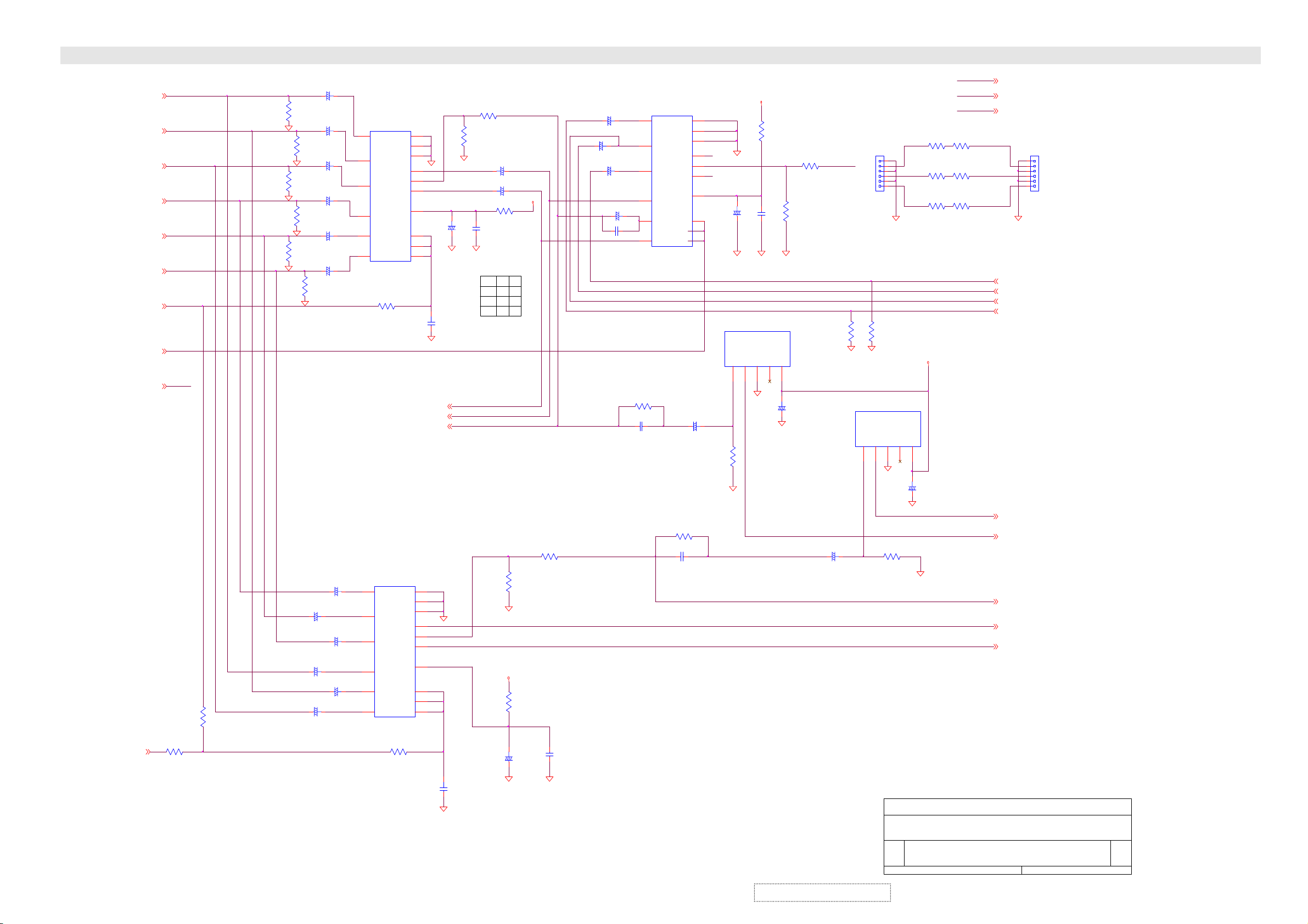
SCHEMATIC DIAGRAM
PB2_CB2P[ 18]
Y2P[18]
V
PR2_CR2P [ 18]
PB1_CB1P[ 18]
V
Y1P[18]
PR1_CR1P [ 18]
V
YUV_SWP[ 1, 18]
15Kn_ MPP[1,12,18]
DPTV _Y
DPTV _Y
R320
0
1/16W
YUV_SPSWP [ 1, 18]
R321
N/0
1/16W
C214
10uF
16V
R358
75
1/16W
V
R360
75
1/16W
V
R362
75
1/16W
+
C217
47uF
16V
+
R359
75
C220
1/16W
10uF
16V
+
C223
10uF
16V
+
R361
75
C229
1/16W
47uF
16V
+
C231
10uF
16V
+
R363
75
1/16W
V
C246
10uF
16V
+
C249
47uF
16V
+
+
C251
10uF
16V
+
C253
10uF
+
16V
C256
47uF
16V
+
C258
10uF
16V
IC3
M5205 5FP
16
11
14
GND 1
I/P 1A
GND 2
GND 3
I/P 2A
OUT 1
OUT 2
8
I/P 3A
OUT 3
1
9 7
16
11
14
Vcc
I/P 1B
I/P 2B
CON 1
CON 2
I/P 3B CON 3
R239
1K
1/16W
IC7
M5205 5FP
GND 1
I/P 1A
GND 2
GND 3
I/P 2A
OUT 1
OUT 2
8
I/P 3A
OUT 3
1
I/P 1B
I/P 2B
CON 1
CON 2
9 7
I/P 3B CON 3
R256
1K
1/16W
15
4
10
V
3
5
Y
6
13
C226
100uF
16V
2
12
C232
100PF
T
50V
V
PTV_CRP[ 13]
PTV_CBP[13]
PTV_Y0P[13]
15
4
10
V
3
5
6
13
Vcc
2
12
T
V
PTV_CB
PTV_CR
V
C265
100PF
50V
R229
0
1/16W
PTV_Y0
R232
2K
1/16W
V
PTV_CR
PTV_CB
PTV_Y0
C228
0.01u F
50V
CON1
CON2
CON3
C219
10uF
16V
+
C221
10uF
+
16V
P9V
R235
10
1/16W
L
H
A
B
B
A
B
A
R246
0
1/16W
R248
2K
1/16W
V
P9V
R254
10
1/16W
C260
+ C259
100uF
16V
V
0.01u F
50V
V
V
+
C222
10uF
16V
+
+
C227
N/47uF
16V
+
C230
10uF
16V
C215
47uF
16V
+
C218
0.01u F
50V
DPTV _Y
R241
180
1/16W
C235
0.01u F
50V
IC2
M5205 5FP
16
11
14
GND 1
I/P 1A
GND 2
GND 3
I/P 2A
OUT 1
I/P 3A
I/P 1B
I/P 2B
I/P 3B CON 3
OUT 2
OUT 3
Vcc
CON 1
CON 2
R247
180
1/16W
C247
0.01u F
50V
8
1
9 7
15
4
10
3
V11
5
6
V12
13
2
12
+
C236
1uF
50V
R243
220K
1/16W
P9V
V
C224
+
100uF
16V
V
IC4
LA721 3
VIDEO IN
H.D. OUT
12345
V
V
R230
10
1/16W
R236
0
1/16W
V13
R237
2K
C225
1/16W
0.01u F
50V
V
V
GND
V.D. OUT
VCC
C237
+
100uF
16V
V
+
C248
2.2uF
50V
V
R405
N/0
1/16W
IC6
LA721 3
J27
T1285-BJST
R407
N/0
1/16W
V
VIDEO IN
H.D. OUT
123
V11
R242
6
5
4
3
2
1
V
GND
V
R250
220K
1/16W
Title
Size Document N um ber
B
N/0
1/16W
V12
R253
N/0
1/16W
V13
R255
N/0
1/16W
P5V_CO L O R
V.D. OUT
VCC
4
5
C241
+
100uF
16V
V
V
VIDEO SYSTEM - YU V SWI TCH M52 055P & HS SEP. LA7213
QPWB11400-1G---
PB_IN
PR_IN
Y0_IN
R319
N/0
1/16W
R240
N/0
1/16W
R244
N/0
1/16W
PB_IN P[ 12]
PR_I N P[12]
Y0_I N P[12]
PB_IN
PR_IN
Y0_IN
V
DPT V _PR P[ 13]
DPT V _Y2 P[ 12]
B1 P[12]
DPT V _PB P[13]
HSYNC_S P P[1]
HSYNC_MPP[1]
DPT V _Y_S P[ 14]
DPT V _CB _S P[ 14]
DPT V _CR_S P[14]
Date: Sheet
VER1.0
J26
T1285-BJST
6
5
4
3
2
1
Rev
1.4
of
11 18Friday , Februar y 2 1, 2003
ViewSonic Corporation
6-11
Confidential – Do Not Copy
Page 41

SCHEMATIC DIAGRAM
PR_INP[11 ]
PB_INP[11]
Y0_ INP[11]
D35
N/RLS4148
Q36
N/2SC2412KBQ
D55
RLS4148
P9V
C277
+
N/22uF
16V
Q32
N/2SC2412KBQ
R276
R277
N/1.5K
N/3.3K
1/16W
1/16W
V
R289
N/12K
1/16W
R291
N/12K
R293
1/16W
N/3.9K
1/16W
V
Q45
DTC144 EKA
V
2SC2412K B Q
V
R269
180
1/16W
R280
820
1/16W
R311
22K
1/16W
V
C273
2.2uF
+
+
50V
737476788012
P5V_ CIRC L E
Q33
C293
R292
0.01uF
180
+
V
V
C297
1uF
50V
R300
220K
1/16W
Q46
DTC144 EKA
50V
IC10
LA721 3
1/16W
R S/H
SENSE I/P
FSC O/P
SCP O /P
727069676564636261595857545352504947464543424140383735
R283
30K
1/16W
V
A5V
VIDEO IN
H.D. OUT
GND
1
2
3
V
P5V_COLOR
R312
3.3K
1/16W
Q40
DTC144 EKA
V
C279
C278
0.1uF
0.1uF
C274
25V
25V
2.2uF
Z
Z
50V
Y2 I /P
U/Q I/P
COLO R
SECAM
Y1 O /P
U/Q O/P
L39
N/0
1/8W
V.D. OUT
VCC
4
5
P5V_COLOR
R306
1K
1/16W
C430
1000P F
50V
V
D57
RLS4148
C280
0.1uF
25V
Z
V/I IN
V/1 O /P
P5V_COLOR
+
+
+
C276
C275
2.2uF
1uF
50V
50V
3
BPH
1H DL
0.22uF
50V
V
C299
100uF
16V
C300
22P F
50V
T
R299
39K
1/16W
DPTV_Y2P[11]
R265
N/10K
1/16W
R53
N/0
1/16W
C284
+
N/47uF
+
B1
DPTV_Y1P[13]
FBP
R279
N/1K
1/16W
15K n_MPP[1, 11,18]
DPTV_HSP[13]
DPTV_VSP[13]
16V
C415
10uF
16V
R406
N/0
1/16W
V
R245
N/2K
1/16W
V
Q35
N/2SC2412KBQ
R285
N/1.5K
1/16W
V
P5V_COLOR
R323
3.3K
1/16W
Q47
DTC144 EKA
V
V
R268
N/2.7K
1/16W
+
C285
N/33uF
16V
T
T
P5V_COLOR
V
C301
100P F
50V
C302
N/33PF
50V
R329
3.3K
1/16W
Q42
DTC144 EKA
Q27
N/2SC2412KBQ
N/2SA1037KQ
R274
N/39K
1/16W
V
R267
N/3.3K
1/16W
N/2SC2412KBQ
R270
N/RLS4148
V
N/1K
1/16W
V
D34
R278
N/5.6K
1/16W
P5V_COLOR
R295
1.2K
1/16W
Q37
2SC2412K B Q
R297
22K
1/16W
V
R302
82K
1/16W
D38
RLS4148
Q31
R298
33K
1/16W
D37
RLS4148
R303
1K
1/16W
Q29
N/2SC2412KBQ
V
R282
N/1.2K
1/16W
R290
N/6.8K
1/16W
Q39
Q34
N/2SA1037KQ
R266
N/100K
1/16W
R273
N/100
1/16W
V
Q28
R271
N/1K
1/16W
V
D36
N/RLS4148
R296
47K
1/16W
2SA1 03 7 KQ
C269
330uF
16V
APL
4.43 MHz
+C288
R381
10
1/16W
+
567
YM I/P
VSM O/ P
M PAL
3.58 MHz
R284
30K
1/16W
C289
2200P F
50V
C287
+
330uF
16V
C298
0.01uF
50V
R301
22K
1/16W
V
V
P9V
V
C304
0.1uF
25V
Z
74HC22 1D
R380
10
1/16W
VCC3 (9 V)
APC
IC12
C270
0.01uF
C272
50V
0.01uF
50V
+
C283
1uF
50V
8
9
111315171819202122242527293132
B O/P
R O/P
TEXTGND2
CHROM A I/P
CGND
V
C291
100uF
16V
IC9
78M05A
3
D54
RLS4148
R304
27K
1/16W
R307
33K
1/16W
16
VCC
1B
1RD1Q2Q
1A
12345
V
G O/P
Y1/SYNC I /P
VOU T
P5V_COLOR
15
1RCEXT
VCC2 (9 V)
V-SEP
HD O/P
C286
2.2uF
+
50V
+
VIN
GND
2
R328
5.6K
1/16W
V
C305
47P F
50V
T
1Q
1C EXT
2CEXT
6
C307
180P F
50V
T
V
ABCL I /P
VCC1 (5 V)
C290
0.01uF
50V
R327
1K
1/16W
Q38
2SC2412K B Q
ViewSonic Corporation
6-12
Confidential – Do Not Copy
P9V
C267
+C266
100uF
16V
R I/P
SYNC. O /P
R287
10K
1/16W
C292
0.01uF
50V
2Q
1Q
7
0.1uF
25V
Z
C271
+
10uF
16V
YS1
B I/P
G I/ P
DEF GND
AF C
VCO
V
1
V
1011121314
2B
2RD
GND 2A
8 9
R310
V
100K
1/16W
R257
10
1/16W
R259
0
1/16W
R263
0
1/16W
V
C281
C282
2.2uF
2.2uF
+
+
50V
50V
YS2
ANA_ B
ANA_ R
ANA_ G
VCC (9V)
H. O/P
Curv e Adjust
FBP I/P
R288
2.2K
1/16W
C294
0.01uF
50V
FBP
R305
12K
1/16W
16
VCC
1CT C
1
C306
180P F
50V
T
G S/ H
VP O/P
DGND
SDA
V
T
C303
33P F
15
50V
2CT C
1RCTC
2
R309
1M
1/16W
B S/H
SCL
34
2RCT C
1RD
34567
V
C268
+
22uF
16V
R262
18K
1/16W
V
U43
TA 1276 AF
P9V
3
C295
+
100uF
16V
P9V
L38
0
1/8W
1011121314
2Q
2A1
2A0
2RD
1A1
1A01Q1Q
GND 2Q
8 9
V
C308
100P F
T
50V
V
Title
Size Do cument Number
B
R260
R261
0
0
1/16W
1/16W
R356
1.2K
1/16W
V
Q30
2SC2412K B Q
R357
1.2K
1/16W
V
P12V
1
C296
+
N/100uF
16V
YPBPR_ HS
D58
RLS4148
Q41
DTC144 EKA
V
R281
100
1/16W
R286
100
1/16W
U44
N/ML7 80 9F A
VOU T
IC11
74H C4 5 38 D
R258
0
1/16W
Q25
2SC2412K B Q
R355
1.2K
1/16W
V
Q26
2SC2412K B Q
R264
18K
1/16W
V
R272
0
1/16W
R275
18K
1/16W
V
VIN
GND
2
+9V
R49
0
1/16W
R308
1K
1/16W
VIDEO SYSTEM - COLOR SPACE TA1276AN
QPWB11400-1G---
Date: Sheet
VER1.0
YPBPR_ R P[9]
YPBPR_ G P[9]
YPBPR_ B P[9]
SCL2 P[1 ,2,7,10,13,14,18]
SDA2 P[1,2, 7, 10,13, 14, 18]
YPBPR_ HS P[9]
YPBPR_ VS P[9]
R322
N/0
1/16W
V
C245
100P F
T
50V
V
Rev
1.4
12 18Friday , Febr uar y 21, 2003
of
Page 42

SCHEMATIC DIAGRAM
V25_MP
AVDD1P[15]
AVDD2P[15]
RD1
0
1/16W
CD2
2200PF
50V
T
VLF
AVDDA3P[15]
AVDDA1P[15]
AVDDA2P[15]
AVDDA4P[15]
AVDDP[15]
AVDDA3
AVDDA1
AVDDA2
AVDDA4
AVDD
AGND4
AGND3
AVDD-BGP[15]
RD9
560
1/16W
XTLI
R352
N/1M
1/16W
CD3
20PF
50V
YD1
14.318MHz
T
SCL2_33P[2,4,7]
SDA2_33P[2,4,7]
P[0. .7]P[1]
RST_DPTVP[1,14,18]
PS_DPTVP[ 1]
ALE_DPTVP[1]
WRn_DPTVP[1]
RDn_DPTVP[1]
VCC3
CD107
0.01uF
50V
CD26
0.1uF
25V
Z
RD2
0
1/16W
T
SDA2P[1,2,7,10,12,14,18]
SCL2P[1,2,7,10,12,14,18]
INT_DPTVP[1]
AVDDA5P[15]
AS_MPP[18]
CD108
0.01uF
50V
DQM_MP[0..7]P[15]
MD_MP[0..63]P[15]
AVDD1
MLF
CD1
2200PF
T
50V
AVDD-BG
IRSET
XTLO
XTLO
CD4
20PF
50V
MA_MP[0..9]P[15]
157
AVDD1
158
MLF
159
AVSS1
162
AVDD2
161
VLF
160
AVSS2
205
AVDDA
181
AVDDA
190
AVDDA
194
AVDDA
199
AVDDA
206
AVSSA
182
AVSSA
191
AVSSA
195
AVSSA
200
AVSSA
32
AVDDB
31
IRSET
25
AVSSB
30
AVSSB
33
AVSSB
163
XTLI /MC LKI N
164
XTLO
RP4
22 ohm
RST
PS_DPTV
ALE
WR#
RD#
RD28 0 1/16W
RD35 0 1/16W
RD16 220 1/16W
RD20 220 1/16W
INT
AVDDA5
AS_MP
CD27
0.1uF
25V
Z
MD_MP3
MD_MP5
MD_MP1
MD_MP0
MD_MP2
8988878685848382797877767574737271706968656463626160595857565554119
MD0
MD1
MD2
MD_MP7
MD_MP4
MD_MP6
MD3
MD4
MD5
MD6
MD7
MD_MP12
MD_MP8
MD_MP10
MD_MP13
MD_MP9
MD_MP11
MD8
MD9
MD10
MD11
MD12
MD13
MD_MP18
MD_MP17
MD_MP15
MD_MP16
MD_MP14
MD14
MD15
MD16
MD17
MD18
MD_MP23
MD_MP27
MD_MP25
MD_MP21
MD_MP20
MD_MP22
MD_MP19
MD19
MD20
MD21
MD22
MD23
MD_MP28
MD_MP26
MD_MP24
MD24
MD25
MD26
MD27
PANELTV MAIN-PICTURE
AS_MP
CD111
0.01uF
50V
V5SF
1
VCC3
VDD
VDD
VDD
VDD
2352668094
V25_MP
VCC3
RD14
4.7K
1/16W
RD22
N/0
1/16W
CD30
1000PF
50V
AD0
AD1
172
171
1 8
2 7
P0
P1
CD109
0.01uF
50V
170
3 6
P2
AD5
AD6
166
3 6
P6
T
CD28
0.1uF
25V
Z
AD7
165
RP6
22 ohm
4 5
P7
SD_33
CD19
N/68PF
50V
RESET
5
SC
ALEPSWR#
1756176
SC_33
CD20
N/68PF
T
50V
CD110
0.01uF
50V
177
AD2
AD3
AD4
169
168
167
1 8
2 7
4 5
P3
P5
P4
SD
RD#SDSC
178
179
180
INT
4
CD29
0.1uF
25V
Z
ADDRSEL
SB5V
LD13
0
1/8W
CD5
0.1uF
25V
Z
RD23
10K
1/16W
MD_MP29
MD28
MD29
VDD
VDD
110
125
AVDDA5
AGND3
BA_MP
DQM_MP1
DQM_MP2
DQM1
INT2
CD35
0.1uF
25V
Z
DQM2
CLKPIP
DQM_MP3
DQM3
HSPIP
T
DQM_MP5
DQM_MP4
116
DQM4
DQM5
VSPIP
CLKMP/CLKRGB
CD12
1uF
50V
CD21
100PF
50V
DQM_MP6
DQM_MP7
117
118
DQM6
DQM7
HSMP/HSRGB
VSMP/VSRGB
VSPIP
HSPIP
CLKPIP
TEST
+
+
CD14
1uF
50V
+
CD16
22uF
16V
+
CD23
22uF
16V
CD106
0.01uF
50V
11499100
BA
MD_MP34
MD_MP31
MD_MP33
MD_MP32
MD_MP30
120
121
MD30
MD31
MD32
MD33
MD34
VDD_ADC
VDD
VDD
VDD
VDD
192
140
156
174
M_VIDEOP[10]
MD_MP35
122
PTV_Y0P[11]
PTV_CRP[11]
PTV_CBP[11]
MD_MP36
123
MD35
24
MD_MP37
124
MD36
VSS
53
M_CP[10]
M_YP[10]
CD31
1000PF
50V
MD_MP39
MD_MP38
127
128
MD37
MD38
MD39
VSS
VSS
VSS
81
67
PS_DPTV
MD_MP40
129
MD40
VSS
95
MD_MP42
MD_MP41
130
131
MD41
VSS
126
111
CD8
10uF
16V
CD9
47uF
16V
CD13
47uF
16V
CD15
47uF
16V
CD17
10uF
16V
CD22
10uF
16V
MD_MP43
132
MD42
MD43
VSS
VSS
141
RD24
N/0
1/16W
CD102
0.01uF
50V
+
+
+
+
+
+
MD_MP44
133
155
MD_MP45
134
MD44
VSS
173
MD45
VSS
MD_MP46
135
193
C
Y1
MD_MP47
136
MD46
VSS
MD_MP48
137
MD47
MD48
C
196
CVBS1
CVBS4
Cr
Cb
CD32
0.1uF
25V
Z
MD_MP49
138
MD49
CVBS3
185
MD_MP50
MD_MP51
139
142
MD50
CVBS_OUT1
189
188
AGND3
MD_MP52
143
MD51
MD52
CVBS_OUT2
CVBS1
183
RD10
27K
1/16W
MD_MP53
MD_MP54
144
145
MD53
MD54
CVBS2
CVBS4
184
186
CD103
0.01uF
50V
MD_MP55
146
197
MD55
CR
MD_MP56
147
207
MD56
CB
MD_MP57
148
MD_MP58
149
MD57
187
CD33
0.1uF
25V
Z
MD_MP59
150
MD58
CCLP1
CD24
0.1uF
25V
Z
MD_MP61
MD_MP60
MD_MP62
MD_MP63
151
152
153
154
MD59
MD60
MD61
MD62
MD63
CCLP2
CCLP3
198
208
CD6
100PF
T
50V
CD10
100PF
T
50V
T
CD104
0.01uF
50V
102
MA0
CD25
100PF
50V
AGND3
103
104
MA1
CD11
0.1uF
25V
Z
MA_MP3
105
MA2
CD7
0.1uF
25V
Z
AGND3
CD34
0.1uF
25V
Z
MA_MP5
MA_MP6
MA_MP4
106
107
108
MA3
MA4
MA5
MA6
RT1
202
MA_MP2
MA_MP1
MA_MP0
DQM_MP0
MA_MP8
MA_MP9
MA_MP7
109
112
113
90919293115
MA7
MA8
MA9
DQM0
RB1
RT2
RB2
TEST
201
203
20423383940414243
CD18
220uF
+
16V
RT1
V25_MP
CD105
0.01uF
50V
RASn_MP
CASn_MP
WEn_MP
CS0n_MP
MCLK_MP
1019897
96
WE#
CS1#
CS0#
RAS#
CAS#
MCLK
HSYNC
VSYNC
CAPD23/R7
CAPD22/R6
CAPD21/R5
CAPD20/R4
CAPD19/R3
CAPD18/G7
CAPD17/G6
CAPD16/G5
CAPD15/G4
CAPD14/G3
CAPD13/G2
CAPD12/B7
CAPD11/B6
CAPD10/B5
CAPD9/B4
CAPD8/B3
CAPD7/R2
CAPD6/R1
CAPD5/R0
CAPD4/G1
CAPD3/G0
CAPD2/B2
CAPD1/B1
CAPD0/B0
VSMP
HSMP
CLKMP
VSSA4
VSSA2
Title
Size Document Number
B
Date: Sheet
34
35
27
R
28
G
29
B
26
VM
36
HFLB
37
VPROT
7
8
9
10
11
12
13
14
15
16
17
18
19
20
21
22
44
45
46
47
48
49
50
51
U45
PNLTVP6730
TP90
LD1
0
1/8W
AGND3
LD2
AGND3
0
1/8W
VIDEO SYSTEM - PANELTV P6730 MAIN-PI CTURE
QPWB11400-1G---
Friday , F ebruary 21, 2003
VER1.0
BA_MP P[15]
RASn_MP P[15]
CASn_MP P[15]
WEn_MP P[15]
CS0n_MP P[15]
MCLK_MP P[15]
39 1/16W
RD3
RD4
39
1/16W
RD5
39
1/16W
VPROT_M
VSPIP P[14]
HSPI P P[14]
CLKPIP P[14]
RD19
0
1/16W
DEFAULT:
PULL LOW
XTLO
AGND4
TP89
CAPD23_ P[14]
CAPD22_ P[14]
CAPD21_ P[14]
CAPD20_ P[14]
CAPD19_ P[14]
CAPD18_ P[14]
CAPD17_ P[14]
CAPD16_ P[14]
CAPD15_ P[14]
CAPD14_ P[14]
CAPD13_ P[14]
CAPD12_ P[14]
CAPD11_ P[14]
CAPD10_ P[14]
CAPD9_ P[14]
CAPD8_ P[14]
CAPD7_ P[14]
CAPD6_ P[14]
CAPD5_ P[14]
CAPD4_ P[14]
CAPD3_ P[14]
CAPD2_ P[14]
CAPD1_ P[14]
CAPD0_ P[14]
VSMP P[14]
HSMP P[14]
CLKMP P[14]
RD13
10K
1/16W
RD15
N/10K
1/16W
XTLO P[14]
DPTV_HS P[12]
DPTV_VS P[12]
DPTV_PR P[11]
DPTV_PB P[11]
DPTV_Y1 P[12]
VCC3
of
13 18
Rev
1.4
ViewSonic Corporation
6-13
Confidential – Do Not Copy
Page 43

SCHEMATIC DIAGRAM
AVDD1_SP[16]
V25_SP
RDS1
0
1/16W
AVDD2_SP[16]
CDS2
2200PF
T
50V
AVDDA 3_SP[16]
AVDDA 1_SP[16]
AVDDA 2_SP[16]
AVDDA 4_SP[16]
AVDD_SP[16]
AVDDA 3_S
AVDDA 1_S
AVDDA 2_S
AVDDA 4_S
AVDD_S
AGND3
AVDD-BG_SP[16]
AVDD-BG_S
14
R404
0
1/16W
RDS9
560
1/16W
AGND4
P5V
XTLO
9 8
U67D
74HCT04D
IN T_DPTV_SP[1]
VCC 3_S
CDSA7
0.01uF
50V
CDS26
0.1uF
25V
Z
CDSA8
0.01uF
50V
AVDDA 5_SP[16]
RDS2
0
1/16W
XTLI_S
SCL_SPP[18]
SDA_SPP[18]
SDA2P[1,2,7,10,12,13,18]
SCL2P[1,2,7,10,12,13,18]
AS_SPP[18]
DQM_SP[0..7]P[16]
MA_SP[0..9]P[16]
MD_SP[0. .63]P[16]
AVDD1_S
MLF_S
CDS1
220PF
T
50V
VLF_S
IR SET_S
XTLI_S
XTLO_S
CDS3
0.1uF
25V
Z
XTLOP[13]
CDS27
0.1uF
25V
Z
157
AVDD1
158
MLF
159
AVSS1
162
AVDD2
161
VLF
160
AVSS2
205
AVDDA
181
AVDDA
190
AVDDA
194
AVDDA
199
AVDDA
206
AVSSA
182
AVSSA
191
AVSSA
195
AVSSA
200
AVSSA
32
AVDDB
31
IRSET
25
AVSSB
30
AVSSB
33
AVSSB
163
XTLI /MC LKIN
164
XTLO
AD0
AD1
172
171
RST_DPTVP[1,13,18]
RD S28 0 1/16W
RD S35 0 1/16W
RDS16
220
1/16W
INT
AVDDA 5_S
AS_SP
XTLO
CDSA9
0.01uF
50V
MD_SP3
MD_SP1
MD_SP0
8988878685848382797877767574737271706968656463626160595857565554119
MD0
MD1
MD_SP2
MD2
MD3
MD_SP4
MD_SP5
MD4
MD5
MD_SP6
MD_SP7
MD6
MD7
MD_SP8
MD8
MD_SP9
MD_SP10
MD9
MD_SP11
MD10
MD11
MD_SP12
MD_SP13
MD12
MD13
MD_SP14
MD_SP15
MD14
MD15
MD_SP17
MD_SP16
MD16
MD17
MD_SP18
MD18
MD_SP20
MD_SP19
MD19
MD20
MD_SP22
MD_SP21
MD21
MD22
MD_SP23
MD_SP24
MD23
MD24
MD_SP25
MD_SP26
MD25
MD26
MD_SP28
MD_SP27
MD27
MD28
MD_SP30
MD_SP29
MD29
MD30
MD_SP32
MD_SP31
MD31
PANELTV SUB-PICTURE
AS_SP
VCC 3_S
V5SF
1
VDD
VDD
VDD
VDD
2352668094
V25_SP
VCC 3_S
RDS14
N/4.7K
1/16W
RDS22
0
1/16W
CDS30
1000PF
50V
VDD
VDD
VDD
VDD
110
125
140
AVDDA 5_S
AGND3
156
AD2
AD3
170
169
RDS20
220
1/16W
CDS28
AD4
168
167
RST
PS1
0.1uF
25V
Z
AD5
AD6
166
T
AD7
165
SD_S
SC_S
CDS19
N/ 68PF
50V
RESET
5
CDSB0
0.01uF
50V
ALEPSWR#
1756176
CDS20
N/ 68PF
T
50V
RD#SDSC
177
178
INT
179
180
CDS29
0.1uF
25V
Z
ADDRSEL
4
SB5V
RDS23
10K
1/16W
LDS14
0
1/8W
CDS5
0.1uF
25V
Z
CDSB1
0.01uF
50V
MD_SP33
120
MD32
VDD
174
DPTV_CR_SP[11]
MD_SP34
121
MD33
VDD
192
DPTV_Y_SP[11]
DPTV_CB_SP[11]
MD_SP35
122
MD34
MD35
VDD_ADC
S_VIDEOP[ 10]
CDS31
1000PF
50V
MD_SP36
MD_SP37
123
124
MD36
VSS
53
24
S_CP[10]
S_YP[10]
MD_SP38
127
MD37
VSS
67
MD_SP39
128
MD38
VSS
81
PS1
MD_SP40
129
MD39
VSS
95
MD_SP41
130
MD40
MD41
VSS
VSS
111
CDS8
10uF
16V
CDS9
47uF
16V
CDS13
47uF
16V
CDS15
47uF
16V
CDS17
10uF
16V
CDS22
10uF
16V
CDSA2
0.01uF
50V
MD_SP42
MD_SP43
131
132
MD42
MD43
VSS
VSS
126
141
MD_SP44
MD_SP45
133
134
MD44
MD45
VSS
VSS
155
173
+
+
+
+
+
+
RDS24
N/0
1/16W
MD_SP47
MD_SP46
MD_SP48
135
136
137
MD46
MD47
MD48
VSS
C
193
196
C1_S
Y1_S
CVBS1_S
CVBS4_S
Cr_S
Cb_S
CDS32
0.1uF
25V
Z
MD_SP50
MD_SP49
138
139
MD49
MD50
CVBS3
CVBS_OUT1
185
188
AGND3
MD_SP51
MD_SP52
142
143
144
MD51
MD52
CVBS_OUT2
CVBS1
189
183
184
RDS10
27K
1/16W
CDSA3
0.01uF
50V
MD_SP54
MD_SP53
145
MD53
MD54
CVBS2
CVBS4
186
MD_SP55
MD_SP56
146
147
MD55
MD56
CR
CB
197
207
CDS33
0.1uF
25V
Z
MD_SP58
MD_SP57
148
149
MD57
187
MD_SP59
150
MD58
MD59
CCLP1
CDS24
0.1uF
25V
Z
MD_SP60
MD_SP61
151
152
MD60
CCLP2
198
CDS10
100PF
T
50V
CDSA4
0.01uF
50V
MD_SP62
153
MD61
MD62
CCLP3
208
T
MD_SP63
154
MD63
CDS6
100PF
50V
CDS25
T
100PF
50V
AGND3
MA_SP0
102
MA0
MA_SP1
MA_SP2
103
104
MA1
MA2
CDS11
0.1uF
25V
Z
AGND3
CDS34
0.1uF
25V
Z
MA_SP3
MA_SP4
105
106
MA3
CDS7
0.1uF
25V
Z
MA4
MA_SP7
MA_SP5
MA_SP9
MA_SP8
MA_SP6
107
108
109
112
113
MA5
MA6
MA7
MA8
MA9
RT1
RB1
RT2
RB2
202
201
203
20423383940414243
CDS12
1uF
50V
CDS14
1uF
50V
CDS18
220uF
+
16V
V25_SP
CDSA5
0.01uF
50V
DQM_SP1
DQM_SP4
DQM_SP2
DQM_SP3
DQM_SP0
90919293115
DQM0
DQM1
DQM2
DQM3
TEST
INT2
CLKPIP
HSPIP
+
+
CDS16
22uF
16V
CDS21
100PF
T
50V
CDS23
22uF
16V
CDS35
0.1uF
25V
Z
DQM_SP6
DQM_SP7
DQM_SP5
116
117
118
DQM4
DQM5
DQM6
VSPIP
CLKMP/CLKRGB
HSMP/HSRGB
VSSA4_S
VSSA2_S
+
+
CDSA6
0.01uF
50V
BA_SP
RASn_SP
CASn_SP
WEn_SP
CS0n_SP
MCLK_SP
11499100
1019897
96
BA
WE#
CS1#
CS0#
RAS#
CAS#
DQM7
VSMP/VSRGB
CLKMP P[13]
CLKPIP_S
TEST_S
LDS1
0
1/8W
LDS2
0
1/8W
Title
Size Document Number
B
Date: Sheet
MCLK
HSYNC
VSYNC
R
G
B
VM
HFLB
VPROT
CAPD23/R7
CAPD22/R6
CAPD21/R5
CAPD20/R4
CAPD19/R3
CAPD18/G7
CAPD17/G6
CAPD16/G5
CAPD15/G4
CAPD14/G3
CAPD13/G2
CAPD12/B7
CAPD11/B6
CAPD10/B5
CAPD9/B4
CAPD8/B3
CAPD7/R2
CAPD6/R1
CAPD5/R0
CAPD4/G1
CAPD3/G0
CAPD2/B2
CAPD1/B1
CAPD0/B0
U46
PNLTVP6730
AGND3
AGND3
VIDEO SYSTEM - PANELTV P6730 SUB-PIC TUR E
QPWB11400-1G---
Friday , F ebruary 21, 2003
VER1.0
BA_SP P[16]
RASn_SP P[16]
CASn_SP P[16]
WEn_SP P[16]
CS0n_SP P[16]
MCLK_SP P[16]
RDS3 22 1/16W
HSPIP P[13]
RDS4 22 1/16W
VSPIP P[13]
34
HSYNC
VSYNC
35
R
27
28
G
B
29
26
36
37
7
8
9
10
11
12
13
14
15
16
17
18
19
20
21
22
44
45
46
47
48
49
50
51
RDS12
22
1/16W
TPD5
DEFAULT:
PULL LOW
RDS19
0
1/16W
VPROT
1 8
2 7
3 6
4 5
1 8
2 7
3 6
4 5
1 8
2 7
3 6
4 5
1 8
2 7
3 6
4 5
1 8
2 7
3 6
4 5
1 8
2 7
3 6
4 5
RDS5 22 1/16W
TPD1
TPD2
TPD3
TPD4
RDS15
N/10K
1/16W
RDS6
22
1/16W
RND1
22 ohm
RND2
22 ohm
RND3
22 ohm
RND4
22 ohm
RND5
22 ohm
RND6
22 ohm
RDS13
10K
1/16W
HSMP P[13]
VSMP P[13]
CAPD23_ P[13]
CAPD22_ P[13]
CAPD21_ P[13]
CAPD20_ P[13]
CAPD19_ P[13]
CAPD18_ P[13]
CAPD17_ P[13]
CAPD16_ P[13]
CAPD15_ P[13]
CAPD14_ P[13]
CAPD13_ P[13]
CAPD12_ P[13]
CAPD11_ P[13]
CAPD10_ P[13]
CAPD9_ P[13]
CAPD8_ P[13]
CAPD7_ P[13]
CAPD6_ P[13]
CAPD5_ P[13]
CAPD4_ P[13]
CAPD3_ P[13]
CAPD2_ P[13]
CAPD1_ P[13]
CAPD0_ P[13]
CLKPIP P[13]
VCC3_S
of
14 18
Rev
1.4
ViewSonic Corporation
6-14
Confidential – Do Not Copy
Page 44

SCHEMATIC DIAGRAM
VADC3
T
AGND3
T
AGND3
AGND3
AGND3
AGND3
AGND3
CD53
+
10uF
16V
CD67
+
10uF
16V
CD71
+
10uF
16V
AVDDA1
CD37
100PF
50V
AVDDA2
CD41
100PF
50V
CD46
0.1uF
25V
Z
CD48
0.1uF
25V
Z
CD50
0.1uF
25V
Z
CD52
0.1uF
25V
Z
AVDD1
AVDD2
AVDD-BG
AVDDA1 P[13]
AVDDA2 P[13]
AVDDA3 P[13]
AVDDA4 P[13]
AVDDA5 P[13]
AVDD P[13]
AVDD1 P[13]
AVDD2 P[13]
AVDD-BG P[13]
LD3
0
1/8W
+
CD36
10uF
16V
LD4
0
1/8W
+
CD40
10uF
16V
LD5
0
1/8W
+
CD45
10uF
16V
LD6
0
1/8W
+
CD47
10uF
16V
LD7
0
1/8W
+
CD49
10uF
16V
LD8
0
1/8W
+
CD51
10uF
16V
CD54
0.1uF
25V
Z
VCCA3
CD68
0.1uF
25V
Z
LD12
0
1/8W
AGND4
CD72
0.1uF
25V
Z
BA_MPP[13]
WEn_MPP[13]
CASn_MPP[13]
RASn_MPP[13]
MCLK_MPP[13]
MA_MP[0..9]P[13]
Place these resistors close to DPTV
RD29 33 1/16W
RD30 33 1/16W
RD31 33 1/16W
RD32 33 1/16W
RD33 33 1/16W
CD42
10PF
T
50V
Option: Do Not Stuff
VCC3_M
CD55
0.1uF
25V
Z
SGRAM DECOUPLING CAPACITORS
CD56
0.1uF
25V
Z
VCC3_M
CD73
1000PF
50V
CD57
0.1uF
25V
Z
CD43
10PF
50V
MD_MP0
MD_MP1
MD_MP2
MD_MP3
MD_MP4
MD_MP5
MD_MP6
MD_MP7
MD_MP8
MD_MP9
MD_MP10
MD_MP11
MD_MP12
MD_MP13
MD_MP14
MD_MP15
MD_MP16
MD_MP17
MD_MP18
MD_MP19
MD_MP20
MD_MP21
MD_MP22
MD_MP23
MD_MP24
MD_MP25
MD_MP26
MD_MP27
MD_MP28
MD_MP29
MD_MP30
MD_MP31
CD74
1000PF
50V
CD44
10PF
T
50V
DQM_MP0
DQM_MP1
DQM_MP2
DQM_MP3
CD58
0.1uF
25V
Z
BAMP
WEnMP
CASnMP
RASnMP
MCLKMP
MA_MP[0..9]
T
U48
D98SD6432AH
4
DQ1
5
DQ2
7
DQ3
8
DQ4
11
DQ6
13
DQ7
74
DQ8
76
DQ9
77
DQ10
79
DQ11
80 81
DQ12 VDDQ
82
DQ13
83
DQ14
85
DQ15
31
DQ16
33
DQ17
34
DQ18
36
DQ19
37
DQ20
39
DQ21
40
DQ22
42
DQ23
45
DQ24
47
DQ25
48
DQ26
50
DQ27
51
DQ28
53
DQ29
54
DQ30
56
DQ31
16
DQM0
71
DQM1
28
DQM2
59
DQM3
14
NC
21
NC
30
CD75
1000PF
50V
NC
CD59
0.1uF
25V
Z
44
CD76
1000PF
50V
VSS
58
VSS
72
VSS
86
CD60
0.1uF
25V
Z
VSS
6
VSSQ
VSSQ
12
32
CD77
1000PF
50V
VSSQ
VSSQ
VSSQ
VSSQ
VSSQ
38
46
52
78
84
CD78
1000PF
50V
VDDDQ0
VDD
VDD
VDD
VDDQ
VDDQDQ5
VDDQ
VDDQ
VDDQ
VDDQ
VDDQ
CKE
CLK
A0
A1
A2
A3
A4
A5
A6
A7
A8
A9
A10/AP
BA0
BA1
WE
CAS
RAS
CS
NC
NC
NC
NC
VSSQ
12
15
29
43
3
910
35
41
49
55
75
67
68
25
26
27
60
61
62
63
64
65
66
24
22
23
17
18
19
20
57
69
70
73
VCC3_M
CD61
0.01uF
50V
VCC3_M
MA_MP0
MA_MP1
MA_MP2
MA_MP3
MA_MP4
MA_MP5
MA_MP6
MA_MP7
MA_MP9
MA_MP8
CD79
1000PF
50V
CD62
0.01uF
50V
CD80
1000PF
50V
CD63
0.01uF
50V
CD81
1000PF
50V
MD_MP32
MD_MP33
MD_MP34
MD_MP35
MD_MP36
MD_MP37
MD_MP38
MD_MP39
MD_MP40
MD_MP41
MD_MP42
MD_MP43
MD_MP44
MD_MP45
MD_MP46
MD_MP47
MD_MP48
MD_MP49
MD_MP50
MD_MP51
MD_MP52
MD_MP53
MD_MP54
MD_MP55
MD_MP56
MD_MP57
MD_MP58
MD_MP59
MD_MP60
MD_MP61
MD_MP62
MD_MP63
DQM_MP0
DQM_MP1
DQM_MP2
DQM_MP3
CD64
0.01uF
50V
U49
D98SD6432AH
4
DQ1
5
DQ2
7
DQ3
8
DQ4
11
DQ6
13
DQ7
74
DQ8
76
DQ9
77
DQ10
79
DQ11
80 81
DQ12 VDDQ
82
DQ13
83
DQ14
85
DQ15
31
DQ16
33
DQ17
34
DQ18
36
DQ19
37
DQ20
39
DQ21
40
DQ22
42
DQ23
45
DQ24
47
DQ25
48
DQ26
50
DQ27
51
DQ28
53
DQ29
54
DQ30
56
DQ31
16
DQM0
71
DQM1
28
DQM2
59
DQM3
14
NC
21
NC
30
CD65
0.01uF
50V
NC
44
VSSQ
VSSQ
VSSQ
VSS
VSS
58
CD66
0.01uF
50V
72
VSS
86
VSSQ
VSS
6
12
32
38
46
VCC3
Title
VID EO SY S TEM - PANELTV MP SGRAM
Size Document Number
QPWB11400-1G---
B
Date: Sheet
VDDDQ0
VDD
VDD
VDD
VDDQ
VDDQDQ5
VDDQ
VDDQ
VDDQ
VDDQ
VDDQ
CKE
CLK
A10/AP
BA0
BA1
WE
CAS
RAS
CS
NC
NC
NC
VSSQ
NC
VSSQ
VSSQ
VSSQ
52
78
84
LD11
0
1/8W
Friday , F ebruary 21, 200 3
VER1.0
CD38
CD39
10PF
50V
of
10PF
T
50V
VCC3_M
Rev
1.4
A0
A1
A2
A3
A4
A5
A6
A7
A8
A9
VCC3_M
12
15
29
43
3
910
35
41
49
55
75
67
68
25
26
27
60
61
62
63
64
65
66
24
22
23
17
18
19
20
57
69
70
73
VCC3_M
CD69
+
22uF
16V
MA_MP0
MA_MP1
MA_MP2
MA_MP3
MA_MP4
MA_MP5
MA_MP6
MA_MP7
MA_MP9
MA_MP8
R353
0
1/16W
RD34
33
1/16W
CD70
0.1uF
25V
Z
T
OPTION: Do Not Stuff
R354
0
1/16W
CS0n_MP P[13]
DQM_MP[0..7] P[13]
MD_MP[0..63] P[13]
15 18
ViewSonic Corporation
6-15
Confidential – Do Not Copy
Page 45
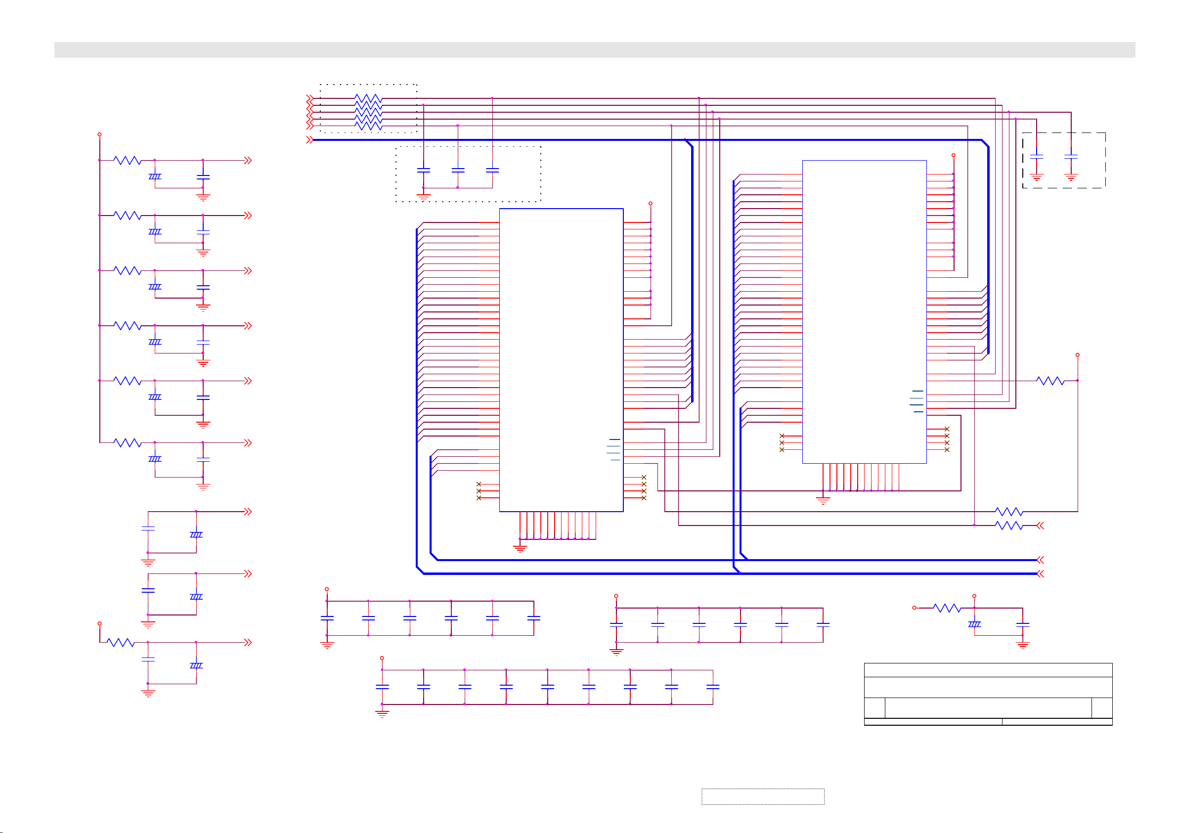
SCHEMATIC DIAGRAM
VADC3_S
LDS3
0
1/8W
LDS4
0
1/8W
LDS5
0
1/8W
LDS6
0
1/8W
LDS7
0
1/8W
LDS8
0
1/8W
CDS36
+
10uF
16V
CDS40
+
10uF
16V
CDS45
+
10uF
16V
CDS47
+
10uF
16V
CDS49
+
10uF
16V
CDS51
+
10uF
16V
AGND3
AGND3
AGND3
AGND3
AGND3
AGND3
CDS37
100PF
T
50V
CDS41
100PF
T
50V
CDS46
0.1uF
25V
Z
CDS48
0.1uF
25V
Z
CDS50
0.1uF
25V
Z
CDS52
0.1uF
25V
Z
CDS54
0.1uF
25V
Z
CDS53
+
10uF
16V
BA_SPP[13]
WEn_SPP[13]
CASn_SPP[13]
RASn_SPP[13]
MCLK_SPP[13]
MA_SP[0..9]P[13]
AVDDA 1_S P[13]
AVDDA 2_S P[13]
AVDDA 3_S P[13]
AVDDA 4_S P[13]
AVDDA 5_S P[13]
AVDD_S P[13]
AVDD1_S P[13]
VCC A3_S
CDS68
0.1uF
25V
Z
CDS67
+
10uF
16V
LDS12
0
1/8W
CDS72
0.1uF
25V
Z
CDS71
+
10uF
16V
AVDD2_S P[13]
AVDD-BG_S P[13]
AGND4
Place these resistors close to DPTV
RDS29 33 1/16W
RDS30 33 1/16W
RDS31 33 1/16W
RDS32 33 1/16W
RDS33 33 1/16W
CDS42
10PF
T
50V
Option: Do Not Stuff
VCC 3_M_S
CDS55
0.1uF
25V
Z
SGRAM DECOUPLING CAPACITORS
CDS73
1000PF
50V
CDS57
0.1uF
25V
Z
CDS74
1000PF
50V
CDS56
0.1uF
25V
Z
VCC 3_M_S
MD_SP0
MD_SP1
MD_SP2
MD_SP3
MD_SP4
MD_SP5
MD_SP6
MD_SP7
MD_SP8
MD_SP9
MD_SP10
MD_SP11
MD_SP12
MD_SP13
MD_SP14
MD_SP15
MD_SP16
MD_SP17
MD_SP18
MD_SP19
MD_SP20
MD_SP21
MD_SP22
MD_SP23
MD_SP24
MD_SP25
MD_SP26
MD_SP27
MD_SP28
MD_SP29
MD_SP30
MD_SP31
DQM_SP0
DQM_SP1
DQM_SP2
DQM_SP3
CDS58
0.1uF
25V
Z
BASP
WEnSP
CASnSP
RASnSP
MA_SP[0..9]
CDS43
10PF
T
50V
CDS44
10PF
T
50V
4
DQ1
5
DQ2
7
DQ3
8
DQ4
11
DQ6
13
DQ7
74
DQ8
76
DQ9
77
DQ10
79
DQ11
80 81
DQ12 VDDQ
82
DQ13
83
DQ14
85
DQ15
31
DQ16
33
DQ17
34
DQ18
36
DQ19
37
DQ20
39
DQ21
40
DQ22
42
DQ23
45
DQ24
47
DQ25
48
DQ26
50
DQ27
51
DQ28
53
DQ29
54
DQ30
56
DQ31
16
DQM0
71
DQM1
28
DQM2
59
DQM3
14
NC
21
NC
30
CDS75
1000PF
50V
NC
CDS59
0.1uF
25V
Z
44
CDS76
1000PF
50V
VSS
58
VSS
72
VSS
VSS
86
CDS60
0.1uF
25V
Z
VSSQ
6
VSSQ
VSSQ
12
32
CDS77
1000PF
50V
VSSQ
38
U50
D98SD 6432AH
VDDDQ0
VDD
VDD
VDD
VDDQ
VDDQDQ5
VDDQ
VDDQ
VDDQ
VDDQ
VDDQ
CKE
CLK
A10/AP
BA0
BA1
WE
CAS
RAS
NC
NC
NC
VSSQ
78
VSSQ
84
VSSQ
52
CDS78
1000PF
50V
NC
VCC 3_M_S
VSSQ
46
A0
A1
A2
A3
A4
A5
A6
A7
A8
A9
CS
12
15
29
43
3
910
35
41
49
55
75
67
68
25
26
27
60
61
62
63
64
65
66
24
22
23
17
18
19
20
57
69
70
73
CDS61
0.01uF
50V
VCC 3_M_S
MA_SP0
MA_SP1
MA_SP2
MA_SP3
MA_SP4
MA_SP5
MA_SP6
MA_SP7
MA_SP9
MA_SP8
CDS79
1000PF
50V
CDS62
0.01uF
50V
CDS80
1000PF
50V
CDS63
0.01uF
50V
CDS81
1000PF
50V
MD_SP32
MD_SP33
MD_SP34
MD_SP35
MD_SP36
MD_SP37
MD_SP38
MD_SP39
MD_SP40
MD_SP41
MD_SP42
MD_SP43
MD_SP44
MD_SP45
MD_SP46
MD_SP47
MD_SP48
MD_SP49
MD_SP50
MD_SP51
MD_SP52
MD_SP53
MD_SP54
MD_SP55
MD_SP56
MD_SP57
MD_SP58
MD_SP59
MD_SP60
MD_SP61
MD_SP62
MD_SP63
DQM_SP0
DQM_SP1
DQM_SP2
DQM_SP3
CDS64
0.01uF
50V
U51
D98SD 6432AH
4
DQ1
5
DQ2
7
DQ3
8
DQ4
11
DQ6
13
DQ7
74
DQ8
76
DQ9
77
DQ10
79
DQ11
80 81
DQ12 VDDQ
82
DQ13
83
DQ14
85
DQ15
31
DQ16
33
DQ17
34
DQ18
36
DQ19
37
DQ20
39
DQ21
40
DQ22
42
DQ23
45
DQ24
47
DQ25
48
DQ26
50
DQ27
51
DQ28
53
DQ29
54
DQ30
56
DQ31
16
DQM0
71
DQM1
28
DQM2
59
DQM3
14
NC
21
NC
30
CDS65
0.01uF
50V
NC
44
VSS
VSS
58
CDS66
0.01uF
50V
VSSQ
VSSQ
VSSQ
VSSQ
VSS
6
12
32
38
46
Title
Size Document Number
B
Date: Sheet
72
VSS
86
VDDDQ0
VDD
VDD
VDD
VDDQ
VDDQDQ5
VDDQ
VDDQ
VDDQ
VDDQ
VDDQ
CKE
CLK
A0
A1
A2
A3
A4
A5
A6
A7
A8
A9
A10/AP
BA0
BA1
WE
CAS
RAS
CS
NC
NC
NC
VSSQ
78
NC
VSSQ
VSSQ
VSSQ
52
84
VCC3_S
VIDEO SY STEM - PANELTV SP SGRAM
QPWB11400-1G---
Friday , February 21, 2003
VER1.0
VCC 3_M_S
12
15
29
43
3
910
35
41
49
55
75
67
68
MA_SP0
25
MA_SP1
26
MA_SP2
27
MA_SP3
60
MA_SP4
61
MA_SP5
62
MA_SP6
63
MA_SP7
64
65
66
MA_SP9
MA_SP8
24
22
23
17
18
19
20
57
69
70
73
LDS11
0
1/8W
VCC 3_M_S
CDS69
+
22uF
16V
OPTION: Do Not Stuff
R351
0
1/16W
RDS34
33
1/16W
CDS70
0.1uF
25V
Z
CDS38
10PF
T
50V
R343
0
1/16W
CS0n_SP P[13]
DQM_SP[0..7] P[13]
MD_SP[0. .63] P[13]
16 18
CDS39
10PF
T
50V
VCC 3_M_S
of
Rev
1.4
ViewSonic Corporation
Confidential – Do Not Copy
6-16
Page 46
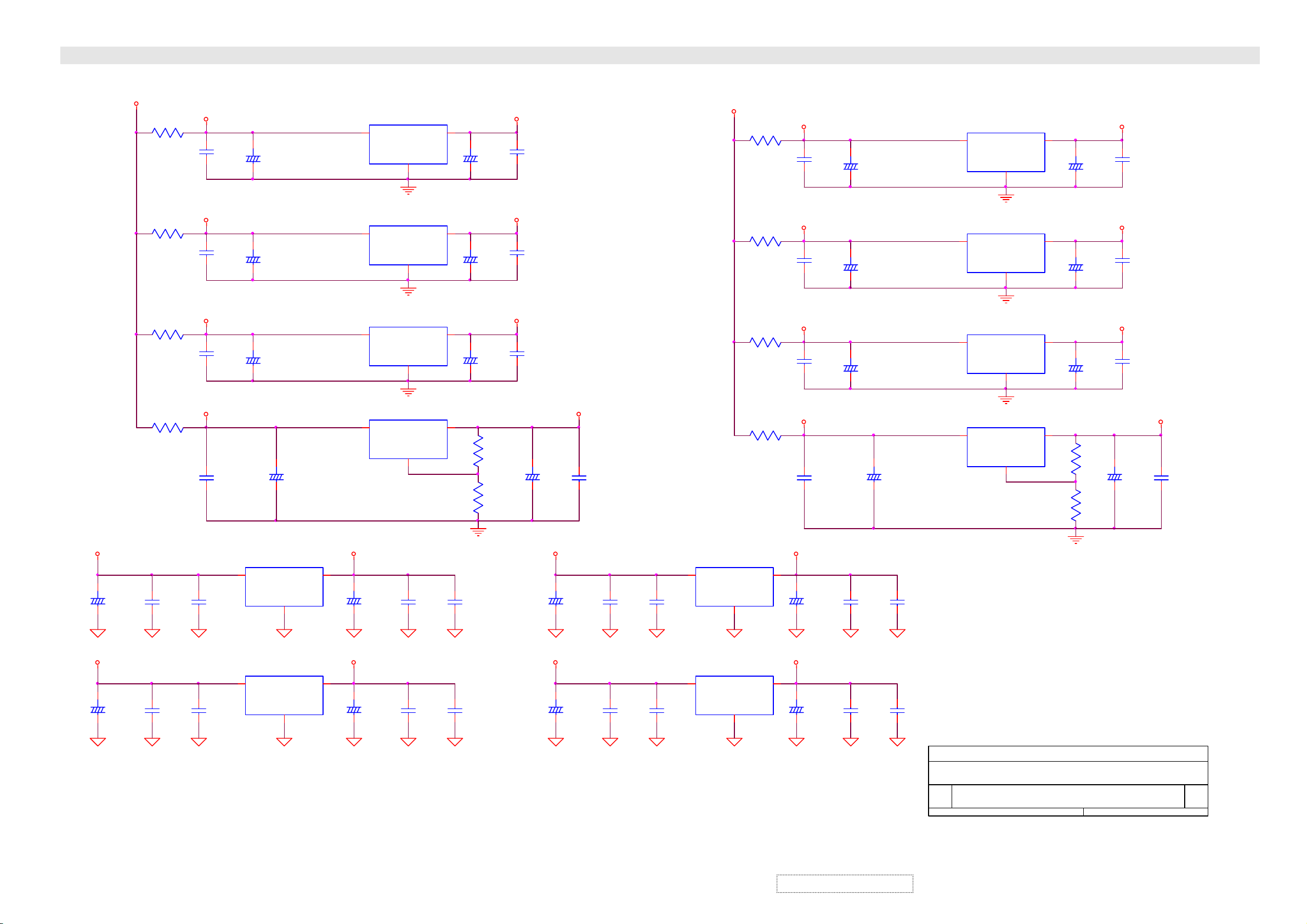
SCHEMATIC DIAGRAM
P5V
P5V
+
D
+
D
C309
100uF
16V
C321
100uF
16V
REG_5V
LD14
0
1/8W
LD18
0
1/8W
LD22
0
1/8W
LD26
0
1/8W
C313
0.1uF
25V
Z
D
C325
0.1uF
25V
Z
D
5VDDA
CD85
0.1uF
25V
Z
5VDDD
CD90
0.1uF
25V
Z
5VDDM
CD95
0.1uF
25V
Z
5VDDM1
CD100
0.1uF
25V
Z
C314
0.01uF
50V
D
C326
0.01uF
50V
D
1
1
+
+
+
U60
BA033
VIN
U62
BA033
VIN
CD82
22uF
16V
CD87
22uF
16V
CD92
22uF
16V
CD97
+
22uF
16V
2
2
REG_5V_S
U52
5VDDA_
5VDDD_
5VDDM_
5VDDM1_
3
VOUT
GND
D
1
1
3
3
V33TMP
C310
+
10uF
16V
D
BA033
VIN
U54
BA033
VIN
AGND3
U56
PJ1086CM33
VIN
U58
LD1805ADJ
VIN
2
2
1
1
GND
GND
GND
GND
C315
0.1uF
25V
Z
D
VOUT
AGND6,7
VOUT
VOUT
VOUT
3
3
2
2
C316
0.01uF
50V
D
+
+
+
For IP00C713
3
VOUT
GND
D
+
D
C322
10uF
16V
C327
0.1uF
25V
Z
D
C328
0.01uF
50V
D
VCCA3
CD84
22uF
16V
VADC3_
CD89
22uF
16V
VCC3_
CD94
22uF
16V
R397
124
1/16W
F
R398
124
1/16W
F
VCCA3
VADC3
VCC3
V25_MP
CD86
0.1uF
25V
Z
CD91
0.1uF
25V
Z
CD96
0.1uF
25V
Z
+
CD99
22uF
16V
P5V
SB5V
C311
+
100uF
16V
D
C323
+
100uF
16V
D
V25_MP
CD101
0.1uF
25V
Z
C317
0.1uF
25V
Z
D
C329
0.1uF
25V
Z
C318
0.01uF
50V
D
C330
0.01uF
50V
D
1
1
U61
BA033
VIN
U63
BA033
VIN
5VDDA_S
5VDDA_S_
V33
3
V33SBV33P
3
CDS85
0.1uF
25V
Z
5VDDD_S
CDS90
0.1uF
25V
Z
5VDDM_S
CDS95
0.1uF
25V
Z
5VDDM1_S
5VDDM1_S_
CDS99
0.1uF
25V
Z
C312
+
10uF
16V
D
C324
+
10uF
16V
D
CDS82
+
22uF
16V
CDS87
+
22uF
16V
CDS92
+
22uF
16V
C319
0.1uF
25V
Z
D
C331
0.1uF
25V
Z
DD
CDS97
+
22uF
16V
5VDDD_S_
5VDDM_S_
C320
0.01uF
50V
D
C332
0.01uF
50V
D
Title
Size Document Number
Date: Sheet
LDS13
0
1/8W
LDS15
0
1/8W
LDS17
0
1/8W
LDS19
0
1/8W
VOUT
GND
2
D
VOUT
GND
2
D
U53
BA033
1
VIN
U55
BA033
1
VIN
U57
PJ1086CM33
3
VIN
U59
LD1805ADJ
3
VIN
VIDEO SY STEM - REGULATOR POWER
QPWB11400-1G---
B
Friday, F ebruary 21, 2003
VOUT
GND
2
VOUT
GND
2
AGND3
VOUT
GND
1
VOUT
GND
1
VER1.0
VCCA3_S
3
VCCA3_S
CDS86
0.1uF
25V
Z
VADC3_S
CDS91
0.1uF
25V
Z
VCC3_S
CDS96
0.1uF
25V
Z
CDSA1
+
22uF
16V
17 18
of
V25_SP
CDSB2
0.1uF
25V
Z
Rev
1.4
AGND6,7
CDS84
+
22uF
16V
3
VADC3_S
CDS89
+
22uF
16V
VCC3_S
2
CDS94
+
22uF
16V
2
V25_SP
R400
124
1/16W
F
R401
124
1/16W
F
ViewSonic Corporation
Confidential – Do Not Copy
6-17
Page 47

SCHEMATIC DIAGRAM
F22
RF ILN1020-1---A
1
C342
220uF
16V
F20
RF ILN1020-1---A
2
V
L29
0.45uH
+C348
D
F21
RCORA1047-1---A
2
D
F23
RCORA1047-1---A
2
D
F26
RCORA1047-1---A
2
D
L24
330uH
J28
CP0055-JJST-
1
2
3
4
5
D
2
V
220uF
16V
+
3
1
3
3
3
1
SB
LG_VS
AC_DET
C417
47uF
16V
3
V
P9V
C335
+
220uF
25V
+
D
+
D
+
D
2
C338
100uF
16V
C346
100uF
16V
C412
100uF
16V
2
D
V
REG_5V_S
+5VSB
AC_DET P[1]
V
F24
RF ILN1020-1---A
F19
RF ILN1020-1---A
C343
+
100uF
16V
C336
0.1uF
25V
Z
P5V
C339
0.1uF
25V
Z
D
REG_5V
C347
0.1uF
25V
Z
D
C413
0.1uF
25V
Z
D
A5V
L_INP[10]
SPK_CTLP[1]
SCART_SO
SCART_SIP[1]
SCL2P[1,2,7,10,12,13,14]
SDA2P[1,2,7,10,12,13,14]
SCART_RGBP[1]
TV_RP[10]
TV_LP[10]
AFT_TUNP[1]
TUN _DETnP[1]
S3_RP[10]
S3_LP[10]
AV3P[10]
S3_YP[10]
S3_CP[10]
R_INP[10]
L_OUT
R_OUT
SUB_WFR
PWR_CTL
COMPOSITE
S2_Y
S2_C
Y1
PB1_CB1
PR1_CR1
Y2
PB2_CB2
PR2_CR2
AVB_DETn
TV
+9VT
+9VT
SCART_SO
SCART_SI
SCL2
SDA2
TV_R
TV_L
AFT_TUN
TUN _DETn
GND_TUNER
S3_R
S3_L
AV3
S3_Y
S3_C
SV2_SW
V2B_DETn
C344
0.1uF
25V
Z
V
C349
100uF
16V
C340
0.01uF
50V
D
P12V
SB5V
C380
0.22uF
50V
M
C350
0.1uF
25V
Z
D
C341
100PF
T
50V
D
P24V
C334
0.22uF
50V
M
COMPOSITEP[10]
S2_YP[10]
S2_CP[10]
Y1P[11]
PB1_CB1P[11]
PR1_CR1P[11]
Y2P[11]
PB2_CB2P[11]
PR2_CR2P[11]
AVB_DETnP[1]
TVP[10]
SV2_SWP[10]
V2B_DETn
JP6
N/Jump
3
+
D
3
C333
+
47uF
50V
J12
CP031A-EJST-
1
2
3
4
5
6
7
8
9
10
A
JP4A
QCNCS1680-1----
A1
A2
A3
A4
A5
A6
A7
A8
A9
B10
A10
B11
A11
B12
A12
B13
A13
B14
A14
B15
A15
B16
A16
V
JP5A
QCNCS1680-1----
A1
A2
A3
A4
A5
A6
A7
A8
A9
B10
A10
B11
A11
B12
A12
B13
A13
B14
A14
B15
A15
B16
A16
D
J16
N/ VCNCP0319-EJST-
1
2
3
4
5
6
7
8
9
V
FROM AV3 PWB
TO AUDIO PWB
A
A
R324
N/0
1/16W
AV1_L
AV1_R
S2_L
S2_R
YUV1_L
YUV1_R
YUV2_L
YUV2_R
RGB_L
RGB_R
S_DET
DVI_L
DVI_R
L_OUT
R_OUT
SUB_WFR
PWR_CTL
B1
B2
B3
B4
B5
B6
B7
B8
B9
B1
B2
B3
B4
B5
B6
B7
B8
B9
AV1_L P[10]
AV1_R P[10]
S2_L P[10]
S2_R P[10]
YUV1_L P[10]
YUV1_R P[10]
YUV2_L P[10]
YUV2_R P[10]
RGB_L P[10]
RGB_R P[10]
S_DET P[1]
FROM AUDIO PWB
DVI_L P[10]
DVI_R P[10]
S3_C P[10]
S3_Y P[10]
R325
N/0
1/16W
D_CTL
RESETQ
TELEXON P[1]
FROM TUNER PWB
C421
0.1uF
25V
Z
L26
10uH
L28
10uH
L30
10uH
C427
0.1uF
25V
Z
L27
10uH
L25
10uH
C419
0.1uF
25V
Z
+5VSB
+
D
C234
47uF
25V
C403
0.22uF
50V
M
C337
+
220uF
16V
D
C345
+
220uF
16V
D
C411
+
220uF
16V
D
+24V
+
V
1
C423
0.1uF
25V
Z
1
1
1
C216
47uF
25V
+
J25
CP0053-JJST-
1
2
3
V
J15
CP0054-JJST-
4
3
2
1
+
C240
47uF
25V
+9V
+
+5VA
C239
47uF
25V
J14
CP0056-JJST-
V
1
2
3
4
SB
5
6
SBP[1]
+
C238
47uF
25V
+5V1
C425
0.1uF
25V
Z
D
+9VT
J21
CP0057-JJST-
1
2
3
4
5
6
7
C200
0.22uF
50V
M
D
C233
47uF
+
25V
GND_TUNER
J11
VCNCP031C-EJST-
1
2
3
4
5
6
7
8
9
10
11
12
0805
JP4B
QCNCS1680-1----
Title
Size D oc um ent N um ber
B
Date: Sheet
PCn_MPU
C1
PCSCS
C2
PCSI
C3
PCSCLK
C4
SSO
C5
C6
C7
C8
C9
C10
C11
C12
C13
C14
C15
C16
JP5B
QCNCS1680-1----
C1
C2
C3
C4
C5
C6
C7
C8
C9
C10
C11
C12
C13
C14
C15
C16
J22
N/CP0306-EJST-
1
AV_B_DET
2
TUN _DETn
SB
3
4
5
6
VID EO SY STEM - CON N EC TOR
QPWB11400-1G
Friday , February 21, 2003
VER1.0
24V
SB5V
SDA2
SCL2
C402
0.22uF
50V
M
D
SCL2
SDA2
SCL_SP
SDA_SP
D
AS_MP
AS_SP
SV2_SW
YUVn_RGB
15Kn_MP
15Kn_SP
SB5V_CPU
D
D
C376
1000PF
50V
RGBn_DVI P[1,3,10]
YUV_SW P[1,11]
YUV_SPSW P[1,11]
AO_SEL P[1]
SDA2 P[1,2,7,10,12,13,14]
SCL2 P[1,2,7,10,12,13,14]
A_MUTEn P[1]
SURR1 P[1]
SURR2 P[1]
R384
N/0
1/16W
R385
0
1/16W
A
D
D
C377
1000PF
50V
AS_MP P[13]
AS_SP P[14]
RST_DPTV P[1,13,14]
YUVn_RGB P[1,9]
15Kn_MP P[1,11,12]
15Kn_SP P[1]
TDO P[1]
TDI P[1]
TMS P[1]
TCK P[1]
C378
1000PF
50V
C379
1000PF
50V
PCn_MPU P[5]
PCSCS P[5]
PCSI P[5]
PCSCLK P[5]
SSO P[5]
P5V
SCL_SP P[14]
SDA_SP P[14]
SCL_MP
SDA_MP
D
18 18
Rev
1.4
of
ViewSonic Corporation
Confidential – Do Not Copy
6-18
Page 48
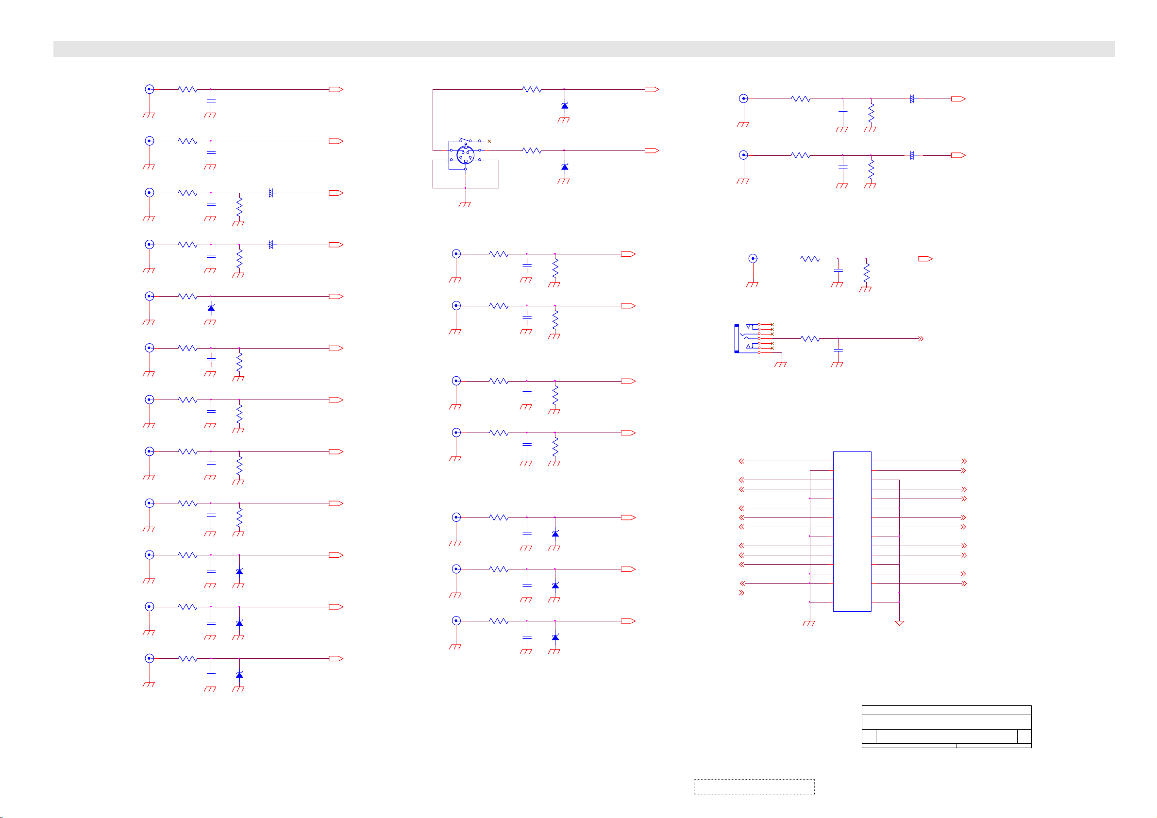
SCHEMATIC DIAGRAM
L O/P
R O/P
RGB L
RGB R
AV_VIDEO
AV_L
AV_R
YUV1_L
YUV1_R
Y1
PB1/CB1
PR1/CR1
J5A
M1076-1----
2
J5B
M1076-1----
2
J24B
P1159-1-4-C
2
J24D
P1159-1-4-C
5
S1B
P1177-1----
8
J17C
P1159-1-4-C
5
J17A
P1159-1-4-C
2
J12C
P1159-1-4-C
5
J12A
P1159-1-4-C
2
J15A
P1158-1-6-C
2
J15C
P1158-1-6-C
5
J15E
P1158-1-6-C
8
1
FE1
0
1/ 8 W
3
FE3
0
1/ 8 W
3
FE5
0
1/ 8 W
6
FE6
0
1/ 8 W
7
FE8
0
1/ 8 W
4
FE10
0
1/ 8 W
1
FE12
0
1/ 8 W
4
FE14
0
1/ 8 W
1
FE16
0
1/ 8 W
1
FE18
0
1/ 8 W
4
FE20
0
1/ 8 W
7
FE21
0
1/ 8 W
CE1
1000PF
50V
CE2
1000PF
50V
CE3
1000PF
50V
CE4
1000PF
50V
ZDA3
UDZ5.1B
CE7
1000PF
50V
CE9
1000PF
50V
CE11
1000PF
50V
CE13
1000PF
50V
CE15
100 PF
T
50V
CE17
100 PF
T
50V
CE18
100 PF
T
50V
RE3
47K
1/16W
RE4
47K
1/16W
RE8
47K
1/16W
RE10
47K
1/16W
RE12
47K
1/16W
RE14
47K
1/16W
ZDA6
UDZ6.8B
ZDA8
UDZ6.8B
ZDA9
UDZ6.8B
CE29
2.2uF
50V
CE30
2.2uF
50V
+
+
L_OUT
R_OUT
RGB_L
RGB_R
COMPOS I T E
AV1_L
AV1_R
YUV1_L
YUV1_R
Y1
PB1_CB1
PR1_CR1
SVIDEO_L
SVIDEO_R
PB2/CB2
PR2/CR2
FE2
0
1/ 8 W
S1A
P1177-1----
4
2
J17D
P1159-1-4-C
5
J17B
P1159-1-4-C
2
J12D
P1159-1-4-C
5
J12B
P1159-1-4-C
2
J15B
P1158-1-6-C
Y2
2
J15D
P1158-1-6-C
5
J15F
P1158-1-6-C
8
6
3
1
5
6
FE7
0
1/ 8 W
3
FE9
0
1/ 8 W
6
FE11
0
1/ 8 W
3
FE13
0
1/ 8 W
3
FE15
0
1/ 8 W
6
FE17
0
1/ 8 W
9
FE19
0
1/ 8 W
FE4
0
1/ 8 W
CE5
1000PF
50V
CE6
1000PF
50V
CE8
1000PF
50V
CE10
1000PF
50V
CE12
100 PF
T
50V
CE14
100 PF
T
50V
CE16
100 PF
T
50V
RE5
47K
1/16W
RE7
47K
1/16W
RE9
47K
1/16W
RE11
47K
1/16W
ZDA4
UDZ6.8B
ZDA5
UDZ6.8B
ZDA7
UDZ6.8B
ZDA1
UDZ5.1B
ZDA2
UDZ5.1B
S2_C
S2_Y
S2_L
S2_R
YUV2_L
YUV2_R
COMPOS I T E
Y2
PB2_CB2
PR2_CR2
DVI L
DVI R
SUB_WFR
S2_Y
S2_C
PB1_CB1
PR1_CR1
PB2_CB2
PR2_CR2
AV_B_DET
J24A
P1159-1-4-C
2
J24C
P1159-1-4-C
5
J3 S1006-1DU--
Y1
Y2
TV
1
4
J40
P1147-1----
2
1
7
6
2
1
4
5
3
COMPOS I T E
S2_Y
S2_C
Y1
PB1_CB1
PR1_CR1
Y2
PB2_CB2
PR2_CR2
AV_B_DET
TV
FE30
0
1/ 8 W
FE31
0
1/ 8 W
FE32
0
1/ 8 W
FE33
0
1/ 8 W
16
15
14
13
12
11
10
9
8
7
6
5
4
3
2
1
CE27
1000PF
50V
CE28
1000PF
50V
JP1
CP1615-132--
A16
A15
A14
A13
A12
A11
A10
A9
A8
A7
A6
A5
A4
A3
A2
A1
CE25
1000PF
50V
CE26
1000PF
50V
RE27
47K
1/16W
B16
B15
B14
B13
B12
B11
B10
B9
B8
B7
B6
B5
B4
B3
B2
B1
Title
Siz e Doc u m e n t Num b er
C
Dat e:
RE25
47K
1/16W
RE26
47K
1/16W
32
31
30
29
28
27
26
25
24
23
22
21
20
19
18
17
AV CONNECTOR(AV3)
DPW B114 10-1G---
Wednesday, Oc t ober 16, 2002
VER1.0
CE31
2.2uF
50V
CE32
2.2uF
50V
+
+
SUB_W FR
PWR_CT L
AV1_L
AV1_R
S2_L
S2_R
YUV1_L
YUV1_R
YUV2_L
YUV2_R
RGB_L
RGB_R
DVI_L
DVI_R
AV1_L
AV1_R
S2_L
S2_R
YUV1_L
YUV1_R
YUV2_L
YUV2_R
RGB_L
RGB_R
12
Sheet
Rev
0.1
of
ViewSonic Corporation
6-19
Confidential – Do Not Copy
Page 49

SCHEMATIC DIAGRAM
TV_L
TV_R
R212
39K
1/16W
R213
39K
1/16W
R206
1K
1/16W
R210
1K
1/16W
C202
10uF
50V
C203
10uF
50V
+
+
T
SDA
5
C212
220PF
50V
MB ( N .C)
6
R201
N/3.3K
1/2W
T
PBNCTU2
7
8
C211
220PF
50V
9
C210
+
1uF
50V
9V
R217
2.2
1/4W
47uF
16V
Q201
1 3
VR201
10K
9V
R223
1K
1/16W
C201
+
31V
NC
IF O/P
10
11
ZD201
N/UPC574J
TU202 TUJH9-805A
IF
IF I/P
N/10uF
50V
R221
150
1/16W
AFT_TUNER
RF AGC O/P
Audio O/P
B+
AFC O/ P
Video O/P
SIF O/P
2
3
4
5
617
VOUT
2SC2412KBQ
R247
N/10K
2
TV
AFT_TUNER
+31V
SCL2
SDA2
R214
100
1/16W
R215
100
1/16W
RF
5V
TU201 TELH 9-818A
12
ANT IN
AGCNCAS
1
2
SCL
3
4
JP2
CP1615 -132--
A16
A15
A14
A13
A12
A11
A10
9
A9
8
A8
7
A7
6
A6
5
A5
4
A4
3
A3
2
A2
1
A1
SDA
SCL
AGC
B16
B15
B14
B13
B12
B11
B10
AOUT
C223
100PF
T
50V
32
31
30
29
28
27
26
25
B9
24
B8
23
B7
22
B6
21
B5
20
B4
19
B3
18
B2
17
B1
DVI_L
DVI_R
L_OUT
R_OUT
SUB_WFR
PWR_CTL
DVI_L
DVI_R
L_OUT
R_OUT
SUB_WFR
PWR_CTL
9V_T
R244
56K
1/16W
IC241
NE555D
R219
680
1/16W
R243
5.6K
1/16W
7
6
81
DIS
THR
VCCGND
RST
TRIG.CVOUT
253
4
R241
27K
1/16W
R242
1.2K
1/16W
C241
0.1uF
16V
D201
N/RLS4148
預留
C245
560PF
50V
9V_T
2SC248 2
R245
330
1/16W
Q241
9V_T
R249
N/150
1/2W
L241
2.2uH
C225
0.01uF
50V
+C224
220uF
16V
P12V
P12V
P31V
P31V
SCL2
SCL2
SDA2
SDA2
16
15
14
13
12
11
10
TV_R
TV_R
TV_L
TV_L
AFT_TUNER
TUNER_DET
AFT_TUNER
R222
0
1/16W
TP201
27
28
LOT
MOA
VCC
VRE
1
2
+
+C221
R220
1K
1/16W
202
n/3.0mH
D241
RLS414 8
D242
N/RLS4148
C216
22uF
16V
26
ROT
PD1
3
C213
0.1uF
50V
C222
2.2uF
50V
C242
0.01uF
500V
C206
1uF
50V
+
+31V
25
NOT
R216
1K
1/16W
+
+
+
23
24
VOA
PD2
D1
4
5
+
C217
1uF
50V
+
C219
4.7uF
50V
L234
N/BLM31A601S
預留
ST_BY 31V USE
R248
1.2K
1/16W
R246
1.2K
1/16W
C243
4.7uF
160V
C207
10uF
50V
WTI
6
C244
0.1uF
50V
D2
+
22
STI
7
R207
3.6K
1/6W
C208
3.3uF
50V
COM
TP202
P31V
21
ITI
SOA
8
C215
0.1uF
50V
+
+31V
R211
13K
1/6W
F
C204
1uF
50V
R218
68K
1/16W
9V_T
ZD241
UPC574J
+
20
WRB
SDT
9
C218
0.047uF
16V
R203
1.2K
1/16W
C205
+
1uF
50V
L242
N/0
1/8W
R204
3.9K
1/16W
R208
1.5K
1/16W
19
10
+
R209
1.5K
1/16W
+
C209
1uF
50V
16
17
18
DO
SRB
NDT
11
C220
0.47uF
50V
Title
Size Document Number
B
Date: Sheet
SOT
12
C214
0.1uF
50V
9V
C226
+
100uF
16V
5V
RF & TUNER
DPWB11410-1G---
DGND
SI
13
3
3
VER1.0
R202
100
1/16W
R205
100
1/16W
IC203
UPC1854ACT
IC204
AT24C02
VCC
A0
TEST
A1
A2
SCL
VSS SDA
J69
Jump
V6 use
VIN
GND
2
VIN
GND
2
S6 use
1
1
5V
C228
0.1uF
+
16V
8
7
6
R224
N/3.9
1/2W
V6 use
R225
N/27
2W
S6 use JUMPER
V6 use 27/2W
SCL2
SDA2
C227
10uF
16V
22Wednes day , Oc t ober 16 , 20 02
R227
10
1/16W
P12V
of
R226
10
1/16W
S6 use 9V
V6 use 12V
Rev
1.1
SCL
ESA
AGND SDA
14 15
1
2
3
4 5
IC201
N/NJM7809FA
VOUT
IC202
NJM7805FA
VOUT
SCL
SDA
ViewSonic Corporation
6-20
Confidential – Do Not Copy
Page 50

SCHEMATIC DIAGRAM
L_IN
R_IN
GND
SURR1
SURR2
L_OUT
R_OU T
SUB_WFR
SPK_CT L
PWR_CTL
SURR1
0
1
---
FROM CP U
LINE_OUT_SEL
MUT E
SURR1
SURR2
10uF
50V
R50
10K
1/16W
Q12
DT C144EKA
DT C144EKA
L_IN
R_I N
SURR2
1
1
0
SDA2
SCL2
LINE_OUT_SEL
SB5V
MUT E
SPK_CT L
P17V
P17V
SDA2
SCL2
SB5V
RR26
2.7K
1/16W
RR24
2.7K
1/16W
+C62
Q13
L_OUT
R_OU T
SUB_WFR
SPK_CT L
PWR_CTL
3D MONO
3D STE REO
OFF
P17V
P17V
LINE_OUT_SEL
SDA2
SCL2
MUT E
SURR1
SURR2
P
L1
12uH
+C63
10uF
50V
R51
10K
1/16W
RR32
10K
1/16W
JA2
CP030A-EJST -
1
2
3
4
5
6
7
8
9
10
SDA2
SCL2
LINE_OUT_SEL
SPK_CT L
+
+C64
CR1
2.2uF
50V
2.2uF
50V
RR25
12K
1/16W
C72
0.22uF
50V
M
FROM AV SELECT OR
QR1
DT C144EKA
QR2
DT C144EKA
QR3
DT C144EKA
CR14
2200PF
50V
RR27
12K
1/16W
C27
0.47uF
16V
C19
3300PF
50V
30
BIN
C32
0.47uF
16V
1
AIN
JA1
CP031C-EJST -
1
2
3
4
5
6
7
8
9
10
11
12
RR3
10K
1/16W
CR30
4700PF
50V
CR5
10uF
+
50V
RR17
100K
RR23
6.8K
1/16W
28
3
BBE2B
BBE2A
RR9
6.8K
1/16W
CR12
0.22uF
16V
CR17
0.22uF
16V
+
C33
4.7uF
50V
C39
0.033uF
16V
1/16W
CR11
0.47uF
16V
C10
N/2200PF
C24
4.7uF
50V
CR15
10uF
+
50V
RR33
N/1
RR34
N/1
CR18
2200PF
50V
For SRS SRN D : RR 9 , RR 23
For 113 2 SRND : RR3 3 , RR 34
C20
0.033uF
16V
29
BBE1B
BBE1A
2
C38
3300PF
50V
R24
2.7K
1/16W
27
BBEOUT B
BBEOUT A
4
R35
+
2.7K
1/16W
AUD MUT E = 0
RR18
10K
1/16W
RR22
1K
1/16W
29
30
R22
N/18K
R37
N/18K
DT C144EK A
R1
C45
0.1uF
25V
Z
120K
1/16W
R5
220K
1/16W
Q2
2SC2412KBQ
+
C5
10uF
50V
+C42
100uF
16V
C51
0.22uF
50V
M
C58
3900PF
50V
R11
47K
1/16W
R25
47K
1/16W
3
R4
47K
1/16W
R9
47K
1/16W
R12
3.9K
1/16W
R30
10
1/16W
U2
LM2940CT12
VOUT
C53
100uF
35V
+
C56
0.22uF
50V
M
Q11
DT C144EKA
Q1
2SC2412KBQ
+
C3
R3
10uF
1.5K
50V
1/16W
A_L
C7
10uF
+
50V
C6
220PF
50V
+C8
22uF
16V
R48
27K
1/16W
+C122uF
ICA3
HEF4052BT
12
X0
14
X1
15
X2
11
X3
1
Y0
5
Y1
2
Y2
4
Y3
6 7
INH VEE
R13
10K
1/16W
1/2VCC
1
VIN
GND
2
1
+
CH1
3
-
8
CH2
9
+
2
16V
A
B
X- CO M
Y-COM
VDD
VSS
U1
NJM4558M
1
2
3
4 5
R16
10K
1/16W
R28
2.2K
1/16W
C46
0. 1 u F
25V
Z
IC2
TDA2616
7
4
6
5
ICA1
C65
+
10
9
13
3
16
8
+ C66
1/16W
R52
47K
1/16W
10uF
50V
R53
47K
1/16W
R55
0
1/16W
R54
N/0
TC4W53FU
10uF
50V
1
COM
2
INH
3
VEE
4
VSS
ICA2
TC4W53FU
1
COM
2
INH
3
VEE
4
VSS
0 = VARI O/P ; 1 = FIX O/P
C12
10uF
+
50V
8
R19
10K
1/16W
+C43
220uF
35V
C50
0. 1 u F
25V
Z
R44
8.2
1/2W
C60
0.022uF
50V
+C30
100uF
16V
R42
8.2
1/2W
7
6
R27
2.2K
1/16W
C57
0.022uF
50V
R21
10K
1/16W
+C14
22uF
16V
R20
3.9K
1/16W
C28
+
470uF
16V
R36
N/0
1/16W
P24V use
P17V no use
1000uF
+
C52
470uF
25V
35V
C59
470uF
16V
+
C13
220PF
50V
P17V use
P24V no use
R57
82
3W
Title
Size Document Num ber
C
Dat e:
C2
AL
AR
RR1
10K
1/16W
SURR1
SURR2
RR8
1.5K
1/16W
28
LIN
RI N
1
C15
1000PF
50V
C25
+
4.7uF
50V
26
TONEINB
TONEINA
5
+C34
4.7uF
50V
C47
N/2200PF
Q15
PN OUT
C1
CR20
0.027uF
16V
RR14
47K
1/16W
C69
0. 1 u F
16V
RR4
10K
1/16W
CR2
0.47uF
16V
RR15
33K
1/16W
RR19
56K
1/16W
27
26
PN I N
S OUT
C2
C3
2
3
CR21
CR25
4700PF
470PF
50V
50V
Q14
DT C144EK A
C21
0.47uF
16V
R26
8.2K
1/16W
23
24
25
TONELB
T ONEHB
T ONEHA
TONELA
6
7
8
R32
8.2K
1/16W
C48
1000PF
C35
50V
0.47uF
16V
C70
0. 1 u F
16V
RR5
3.9K
1/16W
RR7
RR21
2.2K
1/16W
23
C IN
I CR1
NJM2178L
C6
6
CR27
2200PF
50V
1132 S RND ON = 1
390
1/16W
RR16
4.7K
1/16W
+
CR4
10uF
50V
19
22
V REF
MODE1
CF1
CF2
7
8
CR24
0.47uF
63V
CR23
4700PF
50V
CR6
1uF
50V
+
+
CR9
1uF
50V
18
MODE2
CF3
9
M
CR29
0. 1 u F
16V
RR12
3.9K
1/16W
RR13
2.2K
1/16W
RR20
2.2K
1/16W
25
24
S IN
C OU T
C4
C5
5
4
CR26
CR22
0.015uF
0.1uF
50V
50V
BBE ON = 1
VARI OUT = 1
D2
CT H
CVB
+C37
C23
4.7uF
50V
4.7uF
50V
C18
4. 7 u F
+
50V
19
CTL
CVA
12
+C41
4. 7 u F
50V
C22
C17
0.1uF
4.7uF
+
+
16V
50V
20
21
22
PS
OUTB
IC1
NJM1 132
OUTA
VREF
AGC1
AGC2
9
10
11
C44
+C36
0.1uF
1uF
16V
50V
R56
2.2K
1/16W
N/RLS4148
18
17
AUX0
AUX1
VCC
GND
SDA
SCL
13
14
R33
R34
100
100
1/16W
1/16W
17
10
RR28
10K
1/16W
GND
MOC5
16
15
CR10
100uF
16V
RR29
100K
1/16W
12V
RR2
2.2
1/2W
RR10
RR11
10K
100K
1/16W
1/16W
CR7
+
16
15
VCC
MOC6
11
12
CR19
0. 1 u F
16V
CR99
0.01uF
50V
+C31
100uF
16V
CR8
0.01uF
0.1uF
50V
16V
14
MOC2
MOC1
LOUT
ROU T
MOC3
MOC4
13
CR28
0.01uF
50V
RR31
100K
RR30
1/16W
10K
1/16W
R15
4.7K
1/16W
R23
4.7K
1/16W
R31
2.2
1/2W
AL
+C16
0.22uF
50V
C40
+
0.22uF
50V
2. 2 u F
50V
+
C4
2.2uF
+
50V
R2
120K
1/16W
R8
220K
1/16W
R7
1.5K
1/16W
+
20
CR13
4. 7 u F
50V
+
21
CR16
4.7uF
50V
+
C9
4.7uF
50V
+
C11
4.7uF
50V
12V
VARI OUT = 1
C55
SB5V
1uF
10V
Z
R43
1.5K
1/16W
RLS4148
Q10
DT C144EKA
C54
330uF
16V
D1
R41
10K
1/16W
+
R46
82K
1/16W
POWER MUT E
Q6
2SA1037KQ
Q7
2SC2412KBQ
DR5
RLS4148
DR6
RLS4148
DR3
RLS4148
DR7
RLS4148
DR4
RLS4148
R39
2.7K
1/16W
SPK OFF
Q9
DT C144EK A
C61
3900PF
50V
R40
2.7K
1/16W
R45 / R47
S6 use 6. 8K
V6 use 1. 8K
Q8
DT C144EK A
R47
6.8K
1/16W
R45 / R4 7
S6 use 6. 8K
V6 use 1. 8K
R45
6.8K
1/16W
AL
AR
VER1.0
C29
0. 1 u F
25V
Z
+C71
A UDI O CI R CUI T
DPWB11 372-1G-SA
8
VDD
7
CH0
6
CH1
5
ADR
8
VDD
7
CH0
6
CH1
5
ADR
R59
10K
1/16W
R29
2.2
1/2W
R49
1
1/2W
+C49
1000uF
35V
F1
1000P/100V
1
F2
1000P/100V
1
Monday, Oc t ober 14, 2002
12V
Rch
GND
MUT E_1
1/2VCC
+
C67
10uF
50V
C68
10uF
50V
+
0 = MUTE
Q16
DT C144EKA
R18
10K
1/16W
SB5V
12V_0
R17
10K
1/16W
1 = VARI O/P ; 0 = FIX O/P
R38
0.22
1W
2
2
R_OU T
R6
47K
1/16W
R10
47K
1/16W
L_OUT
CP0312- EJS T -
3
3
Sheet
12V_0
Lch
Rch
GND
MUT E_1
1/2VCC
5V
R_OU T
R_O/P
LINE O/ P
L_O/P
L_OUT
Q5
DT C144EK A
Q3
DT C144EK A
PWR_CTL
P17V
(P24V)
BT1
1
2
R
BT2
CP0312- EJS T -
1
2
L
12
of
Rev
0.2
ViewSonic Corporation
6-21
Confidential – Do Not Copy
Page 51

SCHEMATIC DIAGRAM
5V
12V_0
Lch
Rch
GND
MUTE_1
1/2VCC
5V
12V_0
Lch
Rch
GND
MUTE_1
1/2VCC
RS1
22K
1/16W
RS3
47K
1/16W
RS2
22K
1/16W
ICS1
NJM4558M
1
2
3
4 5
RS6
10K
1/16W
RS7
10K
1/16W
CS5
0.047uF
16V
SMD
+CS1
47uF
16V
8
CS2
10uF
16V
CS4
0.1uF
16V
+
RS4
47K
1/16W
7
6
ICS2
TC4W53FU
1
COM
2
INH
3
VEE
4
VSS
Title
Size Doc ument Number
Date: Sheet
SUB_WOOFER
DPWB11372-1G-SA
A
VDD
ADR
CH0
CH1
8
7
6
5
+
CS3
10uF
16V
SUB_WFR
RS5
47K
1/16W
VER1.0
SUB_WOOFER OUT
SUB_WFR
Rev
0.1
of
22Fri day , F ebr uary 21, 2003
ViewSonic Corporation
Confidential – Do Not Copy
6-22
Page 52

P.C. BOARD TOP VIEW VER1.0
U35
RGB
U33
DVI
U35
RGB
MODULE NAME PART NO.
IMAGE BOARD ASS'Y DPWB11400-1G---
U3
Flash
firmware
I01
CPU
ViewSonic Corporation
Confidential – Do Not Copy
7-1
Page 53

P.C.BOARD TOP VIEW VER1.1
MODULE NAME PART NO.
AUDIO AMPLIFIER BOARD ASS'Y
DPWB11372-1G-SA
ViewSonic Corporation
7-
Confidential – Do Not Copy
2
Page 54

P.C. BOARD TOP VIEW VER1.0
MODULE NAME PART NO.
FRONT BUTTON CONTROL BOARD ASS'Y DPWB11372-1G-KS
MODULE NAME PART NO.
AV MODULE BOARD(with Tuner) ASS'Y DPWB11410-1G---
ViewSonic Corporation
7-3
Confidential – Do Not Copy
Page 55

P.C. BOARD TOP VIEW VER1.0
MODULE NAME PART NO.
DC/DC CONVERTER ASS'Y 6871QPH006
SUB POWER BOARD ASS'Y PW-0500
ViewSonic Corporation
MODULE NAME PART NO.
Confidential – Do Not Copy
7-4
Page 56

P.C. BOARD TOP VIEW VER1.0
MODULE NAME PART NO.
LOGIC BOARD ASS'Y 6870QCC023
PANEL MAIN POWER SUPPLY ASS'Y PW-1550
ViewSonic Corporation
MODULE NAME PART NO.
Confidential – Do Not Copy
7-5
Page 57
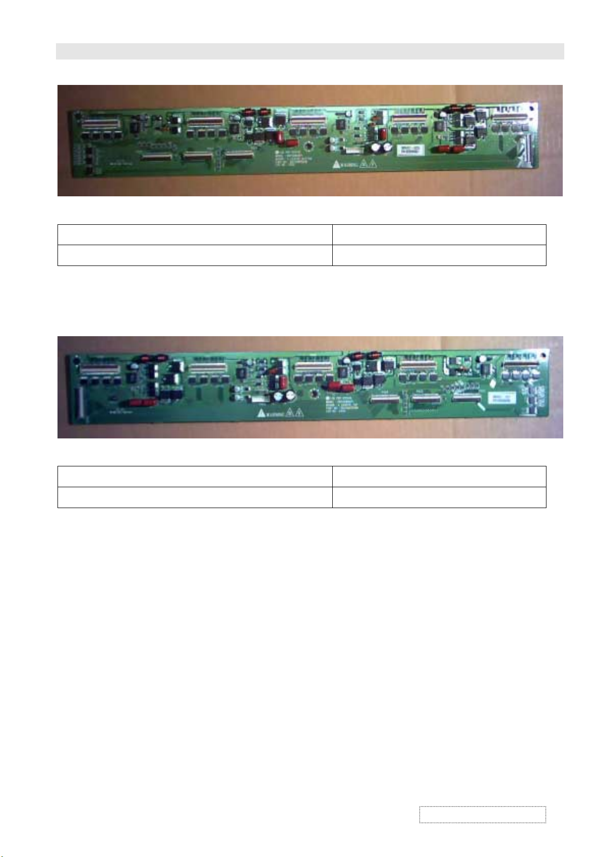
P.C. BOARD TOP VIEW VER1.0
MODULE NAME PART NO.
X-CENTER-BOTTOM ASS'Y 6870QWC001
MODULE NAME PART NO.
X-CENTER-TOP ASS'Y 6870QXC001
ViewSonic Corporation
Confidential – Do Not Copy
7-6
Page 58

P.C. BOARD TOP VIEW VER1.0
MODULE NAME PART NO.
X-LEFT-BOTTOM ASS'Y 6870QMC001
MODULE NAME PART NO.
X-LEFT-TOP ASS'Y 6870QLC001
ViewSonic Corporation
Confidential – Do Not Copy
7-7
Page 59

P.C. BOARD TOP VIEW VER1.0
MODULE NAME PART NO.
X-RIGHT-BOTTOM ASS'Y 6870QSC001
MODULE NAME PART NO.
X-RIGHT-TOP ASS'Y 6870QRC001
ViewSonic Corporation
Confidential – Do Not Copy
7-8
Page 60

P.C. BOARD TOP VIEW VER1.0
MODULE NAME PART NO.
Y-DRV-BOTTOM ASS'Y 6870QFC001
MODULE NAME PART NO.
Y-DRV-TOP ASS'Y 6870QDC001
ViewSonic Corporation
Confidential – Do Not Copy
7-9
Page 61

P.C. BOARD TOP VIEW VER1.0
MODULE NAME PART NO.
Y-SUS BOARD ASS'Y 6870QYC001
Z-SUS BOARD ASS'Y 6870QZC001
ViewSonic Corporation
MODULE NAME PART NO.
Confidential – Do Not Copy
7-10
Page 62

P.C.BOARD TOP VIEW VER1.1
MODULE NAME PART NO.
PDP PANEL MODULE
ASS'Y
P50WXDP1
ViewSonic Corporation
Confidential – Do Not Copy
7-11
Page 63

Recommended Spare Parts List
Model Name: VPW505
Item
1 B-PS-0204-0054 SUB POWER BOARD PW-0500
2 M-MS-0808-8699 PANEL MAIN POWER SUPPLY PW-1550
3 B-SB-0221-0539 DC/DC CONVERTER 6871QPH006
4 B-LB-0203-0068 LOGIC BOARD 6870QCC023
5 M-MS-0808-8853 X-CENTER BOTTOM 6870QWC001
6 M-MS-0808-8854 X-CENTER TOP 6870QXC001
7 M-MS-0808-8850 X-LEFT-BOTTOM 6870QMC001
8 M-MS-0808-8849 X-LEFT-TOP 6870QLC001
9 M-MS-0808-8852 X-RIGHT-BOTTOM 6870QSC001
10 M-MS-0808-8851 X-RIGHT-TOP 6870QRC001
11 M-MS-0808-8848 Y-DRV-BOTTOM 6870QFC001
12 M-MS-0808-8847 Y-DRV-TOP 6870QDC001
13 B-SB-0221-0537 Y-SUS-BOARD 6870QYC001
14 B-SB-0221-0538 Z-SUS BOARD 6870QZC001
15
16 M-FT-0827-0098 PDP FILTER(50" GLASS) PGLS-0014-1----
17 B-SB-0221-0531 IMAGE BOARD DPWB11400-1G---
18 B-AC-0215-0039 AUDIO AMPLIFIER BOARD DPWB11372-1G-SA
19 B-CB-0206-0154 FRONT BUTTON CONTROL PWB DPWB11372-1G-KS
20 B-SB-0221-0532 AV MODULE BOARD(WITH TUNER) DPWB11410-1G---
21 M-MS-0808-8667 REMOTE CONTROL BRC-241BVIEWSON
22 A-PC-0106-0182 POWER CORD QACCF1066-1DX--
23 A-VC-0101-0258 RGB CABLE QCODS1028-1D---
24 M-MS-0808-8700 BATTERY FOR REMOTE CONTROL RBATB0221-1DC--
25 A-UG-0107-0501 MANUAL RDISC1036-1---A
26 M-MS-0808-8705 QUICK STARE GUIDE TMAPT1010-1----
27 P-BX-0601-0822 CARTON SPAKC0723-1R---
28 P-FM-0602-0601 STYROFOAM SPAKA0659-1F--A
29 P-FM-0602-0602 STYROFOAM(TOP) SPAKA0681-1F---
30 P-FM-0602-0603 STYROFOAM(BUTTOM) SPAKA0682-1F---
31 M-MS-0808-8701 SET CUSHION (FRONT) SPAKA0683-1----
32 M-MS-0808-8702 SET CUSHION (REAR) SPAKA0684-1----
33 M-MS-0808-8703 EPE BAG SSAKH0186-1Y--A
34 M-MS-0808-8669 AV INDICATOR PVC HINDP0414-1P--H
35 M-MS-0808-8670 POWER INDICATOR PVC HINDP0415-1P---
36 M-FT-0827-0096 AC FILTER INDICATOR PVC HINDP0416-1P---
37 M-MS-0808-8336 CASE HANDLE JHNDP0020-1----
38 M-LB-0813-0721 SRS CODE TLABD1139-1B---
39 M-MS-0808-8704 G METER TLABW0056-1----
40 M-MS-0808-8357 PE FILM ZTAPEZ500T500--
41 M-LB-0813-0722 BARCODE TLABD1140-1B---
42 M-MS-0808-8707 TAPE ZTAPEQ075T900--
43 M-MS-0808-8356 WRAPPING ZTIE-P155Y1600-
ViewSonic P/N Description Reference No.
M-MS-0808-8856 PDP PANEL MODULE P50WXDP1
M-MS-0808-8706 FULL SET PANEL MODULE SAMPO VVEPP50WXDP1---
ViewSonic Corporation
Confidential – Do Not Copy
8-1
Page 64

Recommended Spare Parts List
Item
44 M-MS-0808-8668 LEG BASE GSTN-0010-F----
45 M-MS-0808-8320 LEG CUSHION GLEGG1016-1----
46 M-MS-0808-8674 LEG FIX ANGLE LANGF0859-1G---
47 M-MS-0808-8675 LEG FIX ANGLE LANGF0860-1G---
48 M-MS-0808-8677 LEG TUBE (L) LANGF0874-1G---
49 M-MS-0808-8678 LEG TUBE ( R ) LANGF0874-1G--A
50 C-FP-0301-0344 BEZEL ASS'LY DMSKP0128-1F---
51 C-BC-0302-0503 REAR COVER GCABB0306-1P--B
52 M-FT-0827-0097 AC FILTER FIX LANGF0854-1P--A
53 M-MS-0808-8672 AC MASTER POWER SW ANGLE LANGF0807-1P---
54 PL-NB-0707-0194 AC MASTER POWER SW KNOB JKNBP0520-1F--A
55 M-MS-0808-8681 ANGLE FOR COLOR FILTER FIX/BOTTOM SIDE LANGQ0022-1P--B
56 M-MS-0808-8855 ANGLE FOR COLOR FILTER FIX/LEFT SIDE LANGQ0023-1P--D
57 M-MS-0808-8683 ANGLE FOR COLOR FILTER FIX/RIGHT SIDE LANGQ0023-1P--E
58 M-CV-0830-2449 AV SOCKET COVER GCOV-0048-1P---
59 M-MS-0808-8684 BUSH FOR REAR CABINET LHLD-0288-1---B
60 M-MS-0808-8693 CUSHION FOR COLOR FILTER ANGLE(L/R) PSLDM0327-1----
61 M-MS-0808-8695 CUSHION FOR COLOR FILTER ANGLE(L/R) PSLDM0336-1----
62 M-MS-0808-8694 CUSHION FOR COLOR FILTER ANGLE(T/B) PSLDM0328-1----
63 M-MS-0808-8696 CUSHION FOR COLOR FILTER ANGLE(T/B) PSLDM0337-1----
64 M-CV-0830-2448 FOOT COVER ANGLE LANGF0875-1P---
65 M-MS-0808-8680 GROUNDING ANGLE LANGF0878-1P---
66 M-MS-0808-8688 HILDER FOR PDP PANEL BOTTOM ( R) LHLDP0089-1F---
67 M-MS-0808-8687 HOLDER FOR PDP PANEL BUTTOM(L) LHLDP0088-1F---
68 M-MS-0808-8685 HOLDER FOR PDP PANEL TOP (L) LHLDP0086-1F---
69 M-MS-0808-8686 HOLDER FOR PDP PANEL TOP( R ) LHLDP0087-1F---
70 M-MS-0808-8691 LIGHT GUIDER PREFL0065-1F---
71 M-MS-0808-8673 MAIN BOARD ANG (L) LANGF0856-1P---
72 M-MS-0808-8676 MAIN BOARD ANG( R ) LANGF0863-1P--A
73 M-MS-0808-8671 PDP PANEL ANGLE LANGF0655-1P---
74 PL-NB-0707-0205 POWER INPUT KNOB/VOLUME KNOB JKNBP0641-1F---
75 M-SW-0815-0211 PUSH POWER SW QSW-P1250-11W1-
76 M-SCW-0824-0793 SCREW CAB-B XTTSQ40P16000--
77 M-SCW-0824-0788 SCREW FOR AC FILTER FIX XBPSD30P08JS0--
78 M-SCW-0824-0792 SCREW FOR AC FILTER FIX XBSSQ30P08000--
79 M-SCW-0824-0463 SCREW FOR AC MASTER POWER SW ANGLE XEASD30P10000--
80 M-MS-0808-8327 SCREW FOR ANGLE XBPSC40P10JS---
81 M-SCW-0824-0794 SCREW FOR AV ANGLE LX-BZ1034-1----
82 M-SCW-0824-0789 SCREW FOR AV SOCKET COVER XBPSQ30P06JS0--
83 M-SCW-0824-0791 SCREW FOR BUSH XBPSQ80P30JS0--
84 M-SCW-0824-0466 SCREW FOR COLOR FILTER ANGLE XETSD40P16000--
85 M-SCW-0824-0788 SCREW FOR DOUND/MAIN BOARD/AV ANGLE XBPSD30P08JS0--
86 M-SCW-0824-0786 SCREW FOR FAN XBBSD40P30JS0--
87 M-SCW-0824-0788 SCREW FOR FOOT COVER ANGLE XBPSD30P08JS0--
88 M-SCW-0824-0463 SCREW FOR FRONT BUTTON CONTROL PWB XEASD30P10000--
89 M-SCW-0824-0788 SCREW FOR HOLDER XBPSD30P08JS0--
ViewSonic P/N Description Reference No.
ViewSonic Corporation
Confidential – Do Not Copy
8-2
Page 65

Recommended Spare Parts List
Item
90 M-SCW-0824-0466 SCREW FOR HOLDER XETSD40P16000--
91 M-SCW-0824-0790 SCREW FOR LEG ANGLE XBPSQ40P12JS0--
92 M-SCW-0824-0465 SCREW FOR LEG FIX ANGLE XETSD40P12000--
93 M-MS-0808-8327 SCREW FOR MAIN BOARD ANGLE XBPSC40P10JS---
94 M-SCW-0824-0788 SCREW FOR PCB ANGLE XBPSD30P08JS0--
95 M-SCW-0824-0792 SCREW FOR PUSH POWER SW XBSSQ30P08000--
96 M-SCW-0824-0787 SCREW FOR REAR COVER(CAB-B) XBJSQ30P08000--
97 M-SCW-0824-0465 SCREW FOR SPEAKER XETSD40P12000--
98 M-SCW-0824-0788 SCREW FOR SPONGE FOR REAR COVER (CAB-B) XBPSD30P08JS0--
99 E-SK-0412-0074 SPEAKER RSPK-L005-1CFJ-
100 M-MS-0808-8692 SPONGE FOR PWB PSLDM0326-1P--A
101 M-MS-0808-8697 SPONGE FOR REAR COVER(CAB-B) PSLDM0341-1----
102 M-MS-0808-8698 SPONGE FOR FOOT COVER ANGLE PSLDM0342-1----
103 M-MS-0808-8689 SPONGE FOR SPEAKER PCUSS0120-1P---
104 M-MS-0808-8679 SUPPORT ANGLE LANGF0877-1P---
105 M-MS-0808-8690 Wall Mount Kit PE-50WB06
ViewSonic P/N Description Reference No.
ViewSonic Corporation
Confidential – Do Not Copy
8-3
Page 66

EXPLODED VIEW
VER1.0
ViewSonic Corporation
9-1
Confidential – Do Not Copy
Page 67
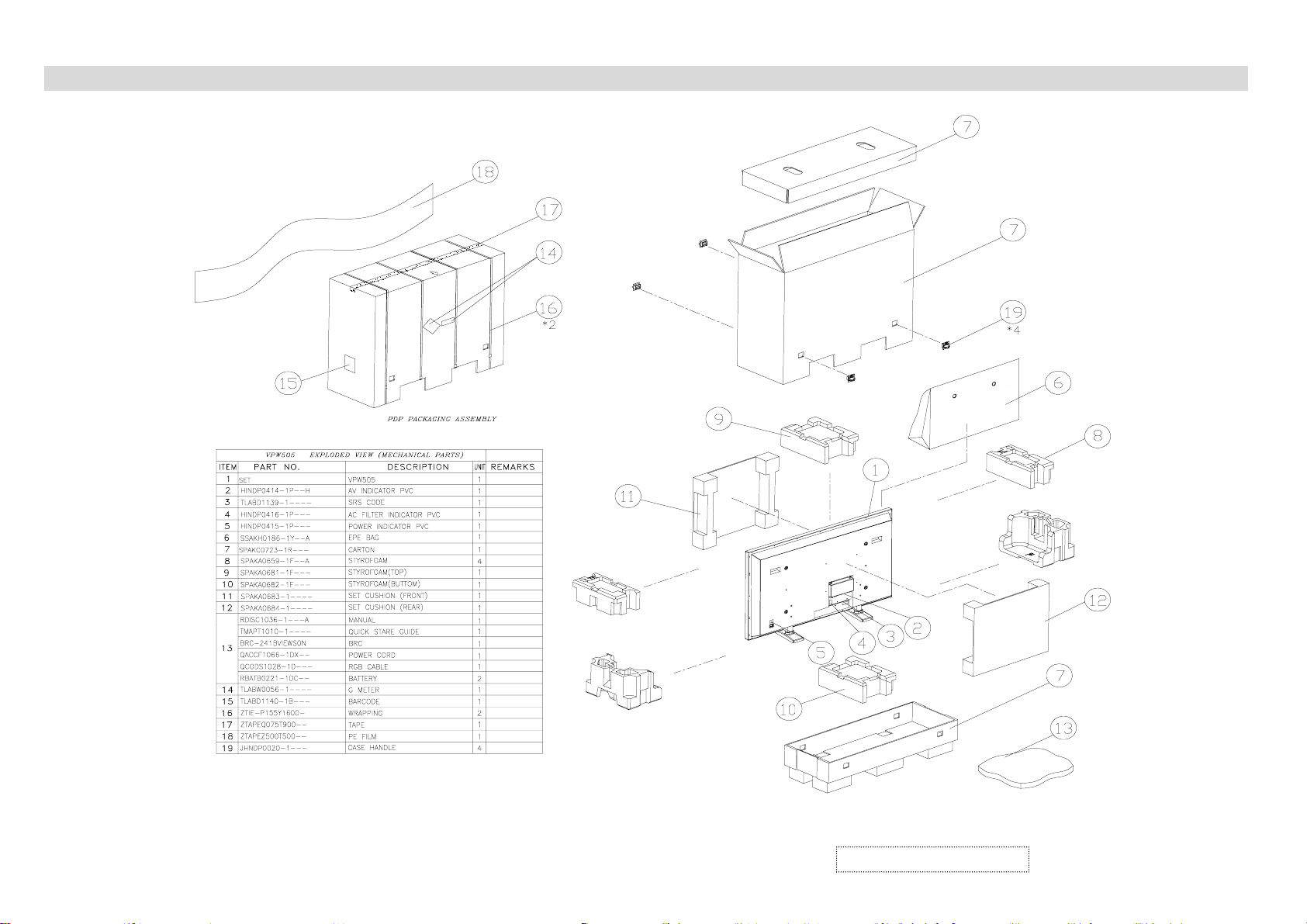
PACKING OF THE LIST V
ER1.0
ViewSonic Corporation
10-1
Confidential – Do Not Copy
Page 68

*Readers Response*
Dear Readers:
Thank you in advance for your feedback on our Service Manual,which allows continuous improvement
of our products. We would appreciate your completion of the Assessment Matrix below, for return to ViewSonic
Corporation.
Assessment
A. What do you think about the content after reading VPW505 Service Manual?
tinU tnellecxE dooG riaF daB
SPECIFICATION
THEORY OF OPERATION
TROUBLE SHOOTING FLOW CHART
ADJUSTMENT
EXPLODED VIEW AND MECHANICAL PARTS LIST
ELECTRICAL PARTS LIST
BLOCK DIAGRAM
SCHEMATIC DIAGRAMS
WIRING DIAGRAM
PCB LAYOUT
B.Are you satisfied with the VPW505 service manual?
metI tnellecxE dooG riaF daB
tnetnoClaunaMecivreS.1
tuoyaLlaunaMecivreS.2
gnitsildnamrofehT.3
C. Do you have any other opinion or suggestion about this service manual?
Readers basic data:
:emaN:eltiT
:ynapmoC
:ddA
:leT:xaF
:liam-E
After completing this form, please return it to ViewSonic Quality Assurance
1-909-444-8654.
(marc.maupin@viewsonic.com)
You may also e-mail any suggestions to the Director of Quality Assurance
in the USA at facsimile
 Loading...