

Page 1

VP2458
Monitor
User Guide
IMPORTANT: Please read this User Guide to obtain important information on installing and using your product in
a safe manner, as well as registering your product for future service. Warranty information contained in this User
Guide will describe your limited coverage from ViewSonic® Corporation, which is also found on our web site at
http://www.viewsonic.com in English, or in specific languages using the Regional selection box in the upper right
corner of our website. “Antes de operar su equipo lea cu idadosamente las instrucciones en este manual”
Model No. VS17557
P/N: VP2458
Page 2

Thank you for choosing ViewSonic®
As a world-leading provider of visual solutions, ViewSonic® is dedicated to exceeding
the world’s expectations for technological evolution, innovation, and simplicity. At
ViewSonic®, we believe that our products have the potential to make a positive
impact in the world, and we are confident that the ViewSonic® product you have
chosen will serve you well.
Once again, thank you for choosing ViewSonic®!
2
Page 3

Safety Precautions
Please read the following Safety Precautions before you start using the device.
• Keep this user guide in a safe place for later reference.
• Read all warnings and follow all instructions.
• Sit at least 18" (45 cm) away from the device.
• Allow at least 4" (10 cm) clearance around the device to ensure proper
ventilation.
• Place the device in a well-ventilated area. Do not place anything on the device
that prevents heat dissipation.
• Do not use the device near water. To reduce the risk of fire or electric shock, do
not expose the device to moisture.
• Avoid exposing the device to direct sunlight or other sources of sustained heat.
• Do not install near any heat sources such as radiators, heat registers, stoves, or
other devices (including amplifiers) that may increase the temperature of the
device to dangerous levels.
• Use a soft, dry cloth to clean the external housing. For more information, refer to
the "Maintenance" section on page 62.
• Oil may collect on the screen as you touch it. To clean the greasy spots on the
screen, refer to the "Maintenance" section on page 62.
• Do not touch the screen surface with sharp or hard objects, as it may cause
damage to the screen.
• When moving the device, be careful not to drop or bump the device on anything.
• Do not place the device on an uneven or unstable surface. The device may fall
over resulting in an injury or a malfunction.
• Do not place any heavy objects on the device or connection cables.
• If smoke, an abnormal noise, or a strange odor is present, immediately turn the
device off and call your dealer or ViewSonic®. It is dangerous to continue using
the device.
• Do not attempt to circumvent the safety provisions of the polarized or
grounding-type plug. A polarized plug has two blades with one wider than the
other. A grounding-type plug has two blades and a third grounding prong. The
wide blade and the third prong are provided for your safety. If the plug does not
fit into your outlet, obtain an adapter and do not attempt to force the plug into
the outlet.
3
Page 4

• When connecting to a power outlet, DO NOT remove the grounding
prong. Please ensure grounding prongs are NEVER REMOVED.
• Protect the power cord from being treaded upon or pinched,
particularly at the plug, and at the point where it emerges from the
equipment. Ensure that the power outlet is located near the equipment
so that it is easily accessible.
• Only use attachments/accessories specified by the manufacturer.
• When a cart is used, use with caution when moving the cart/equipment
combination to avoid injury from tipping over.
• Disconnect the power plug from the AC outlet if the device is not being used for
a long period of time.
• Refer all servicing to qualified service personnel. Service will be
required when the unit has been damaged in any way, such as:
if the power supply cord or plug is damaged
if liquid is spilled onto or objects fall in the unit
if the unit is exposed to moisture
if the unit does not operate normally or has been dropped.
• NOTICE: LISTENING THROUGH EAR-/HEADPHONES AT A HIGH VOLUME FOR
EXTENDED PERIODS CAN CAUSE HEARING DAMAGE/HEARING LOSS. When using
ear-/headphones, adjust the volume to appropriate levels, or hearing damage
may result.
• NOTICE: THE MONITOR MAY OVERHEAT AND SHUTDOWN! If the device shuts
down automatically, please turn on your monitor again. After rebooting, change
your monitor's resolution and refresh rate. For details, please refer to the
graphics card's user guide.
4
Page 5

Contents
Safety Precauons ........................................................................... 3
Introducon ...................................................................................7
Package Contents ........................................................................................................... 7
Product Overview ..........................................................................................................8
Inial Setup ..................................................................................... 9
Installing the Stand ........................................................................................................9
Wall Mounng .............................................................................................................11
Using the Security Slot ................................................................................................. 13
Making Connecons ...................................................................... 14
Connecng to Power ....................................................................................................14
Connecng External Devices ........................................................................................15
HDMI Connecon .................................................................................................. 15
DisplayPort Connecon .........................................................................................16
USB Connecon ..................................................................................................... 17
VGA Connecon ....................................................................................................18
Using the Monitor .........................................................................19
Adjusng the Viewing Angle ........................................................................................ 19
Height Adjustment ................................................................................................19
Tilt Angle Adjustment ............................................................................................ 20
Screen Orientaon Adjustment (Monitor Pivot) ...................................................20
Swivel Angle Adjustment ....................................................................................... 22
Turning the Device On/O ........................................................................................... 23
Using the Control Panel Keys .......................................................................................24
Quick Menu ........................................................................................................... 24
Hot Keys .................................................................................................................26
Conguring the Sengs ...............................................................................................29
General Operaons ............................................................................................... 29
On-Screen Display (OSD) Menu Tree ..................................................................... 32
Menu Opons ........................................................................................................ 38
Advanced Features and Sengs ....................................................49
Colorbraon ................................................................................................................. 49
Auto Pivot ....................................................................................................................50
Firmware Update ......................................................................................................... 51
5
Page 6

Appendix .......................................................................................53
Specicaons ............................................................................................................... 53
Glossary ....................................................................................................................... 55
Troubleshoong ........................................................................................................... 60
Maintenance ................................................................................................................ 62
General Precauons ..............................................................................................62
Cleaning the Screen ............................................................................................... 62
Cleaning the Case .................................................................................................. 62
Disclaimer .............................................................................................................. 62
Regulatory and Service Informaon ...............................................63
Compliance Informaon ..............................................................................................63
Industry Canada Statement ................................................................................... 63
CE Conformity for European Countries..................................................................64
Declaraon of RoHS2 Compliance ......................................................................... 64
Indian Restricon of Hazardous Substances .......................................................... 65
Product Disposal at End of Product Life ................................................................65
Copyright Informaon .................................................................................................. 66
Customer Service ...................................................................................................67
Limited Warranty ...................................................................................................68
Mexico Limited Warranty ......................................................................................71
6
Page 7

Introduction
Package Contents
• Monitor
• Power cord
• Video cable
• Quick start guide
NOTE: The power cord and video cables included in your package may vary
depending on your country. Please contact your local reseller for more
information.
7
Page 8
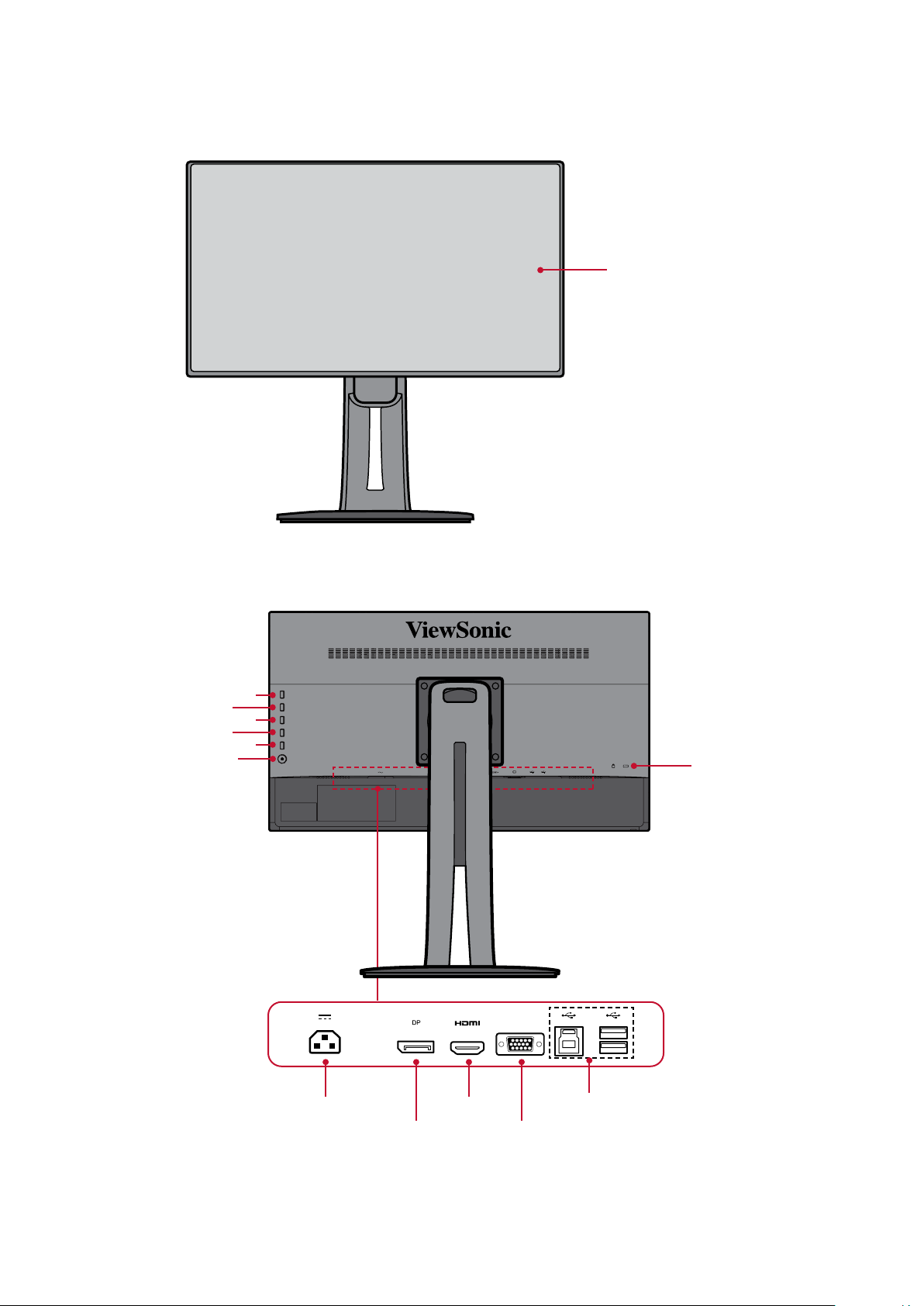
Product Overview
Front View
Display screen
Rear View
Power button
1
2
3
4
5
Security Slot
VGA
AC IN jack
DisplayPort VGA port
USB portsHDMI port
NOTE: For more information about the 1/2/3/4/5 key and its functions, refer to
“Hot Keys” on page 26.
8
Page 9
Inial Setup
This secon provides detailed instrucons for seng up your monitor.
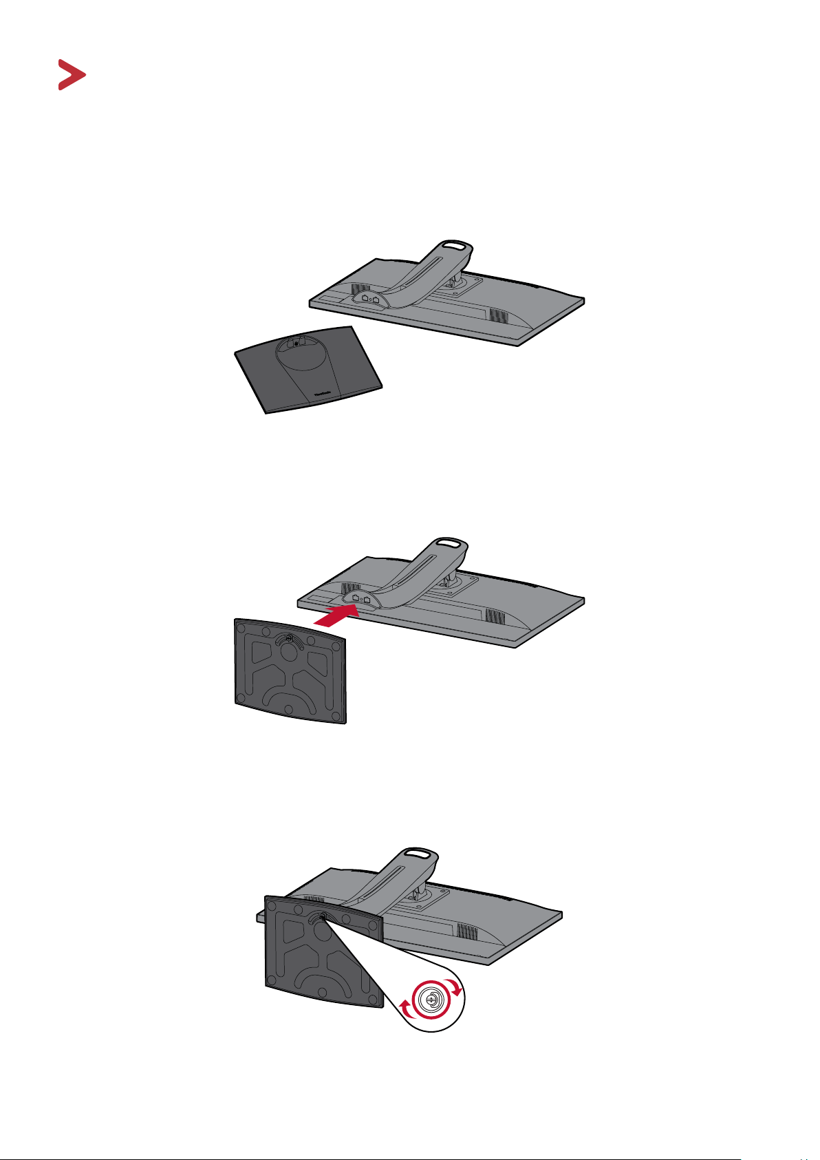
Installing the Stand
1. Place the monitor on a at, stable surface with the screen facing down.
2. Align and connect the two (2) points on the monitor stand’s base with the
monitor stand’s neck.
3. Use the captured screw in the monitor stand’s base and secure it to the monitor
stand’s neck.
9
Page 10
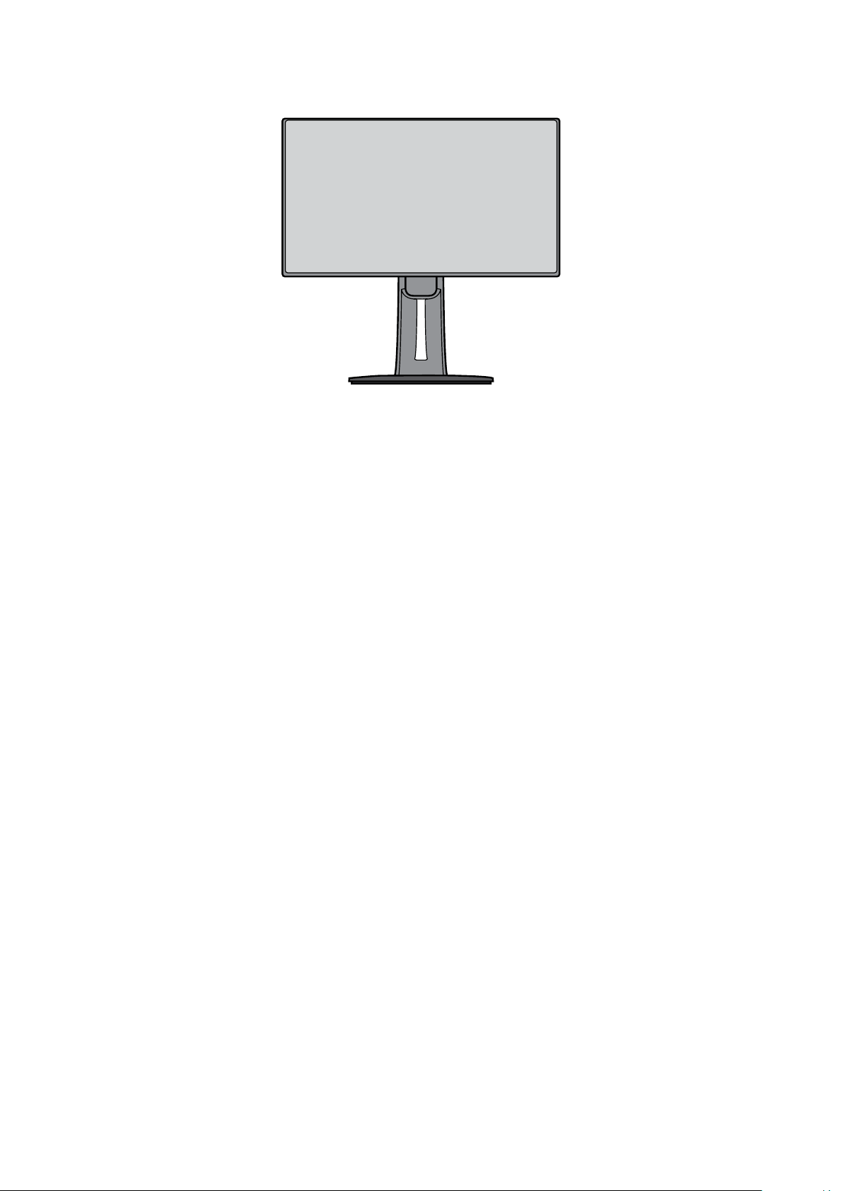
4. Li the device into its upright posion on a at, stable surface.
NOTE: Always place the device on a at, stable surface. Failure to do so may
cause the device to fall and damage the device and/or result in personal
injury.
10
Page 11
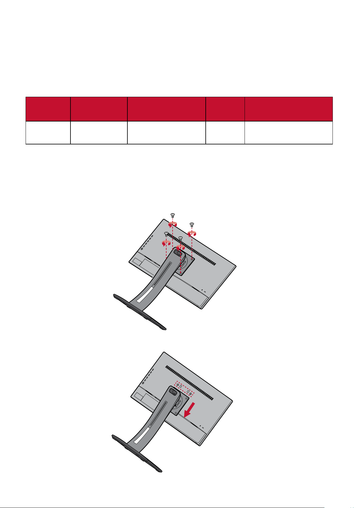
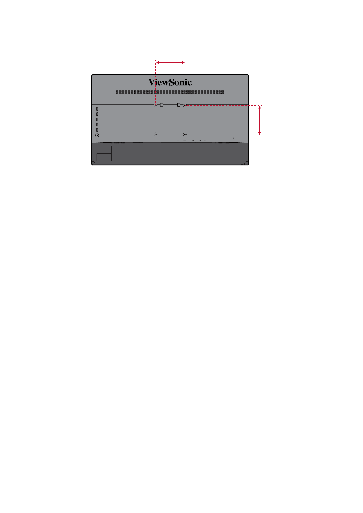
Wall Mounng
Refer to the table below for the standard dimensions for wall mount kits.
NOTE: For use only with a UL cered wall mount kit/bracket. To obtain a wall-
mounng kit or height adjustment base, contact ViewSonic® or your
local dealer.
Maximum
Loading
14 kg 100 x 100 mm 115 x 115 x 2.6 mm Ø 5 mm
NOTE: Wall mount kits are sold separately.
1. Turn o the device and disconnect all cables.
2. Place the device on a at, stable surface with the screen facing down.
3. Remove the four (4) screws securing the stand to the monitor.
Hole paern
(W x H)
Interface Pad
(W x H x D)
Pad Hole
Screw Specicaon &
Quanty
M4 x 10 mm
4 pieces
4. Pull down slightly to disengage the hooks. Then remove the stand.
11
Page 12
5. Aach the mounng bracket to the VESA mounng holes at the rear of the
device. Then secure it with four (4) screws (M4 x 10 mm).
100 mm
100 mm
6. Follow the instrucons that come with the wall mounng kit to mount the
monitor onto the wall.
12
Page 13
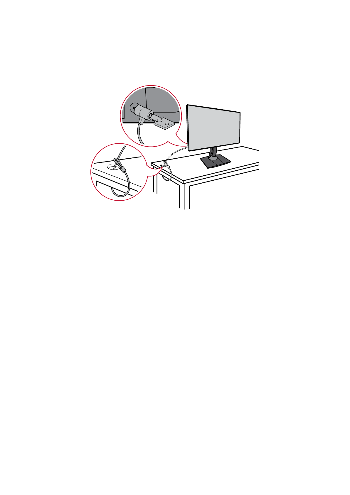
Using the Security Slot
To help prevent the device from being stolen, use a security slot locking device to
secure the device to a xed object.
Below is an example of seng up a security slot locking device on a table.
13
Page 14
Making Connecons
This secon guides you on how to connect the monitor with other equipment.
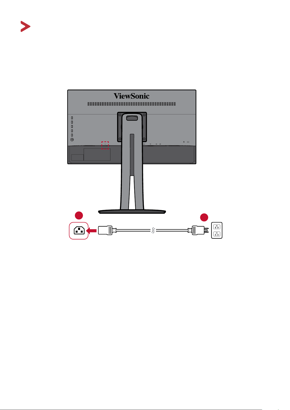
Connecng to Power
1. Connect the power cord to the AC IN jack at the rear of the device.
2. Connect the power cord plug to a power outlet.
1
2
14
Page 15
Connecng External Devices
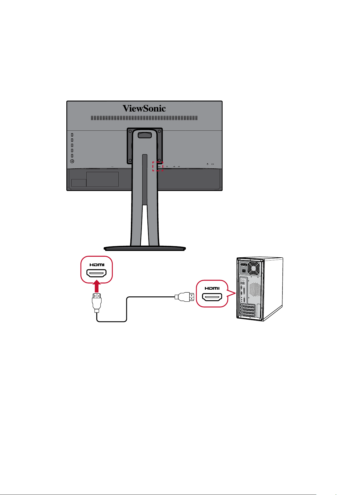
HDMI Connecon
Connect one end of an HDMI cable to the HDMI port of your monitor. Then connect
the other end of the cable to the HDMI port of your computer.
NOTE: The monitor is equipped with one HDMI 1.4 port.
15
Page 16
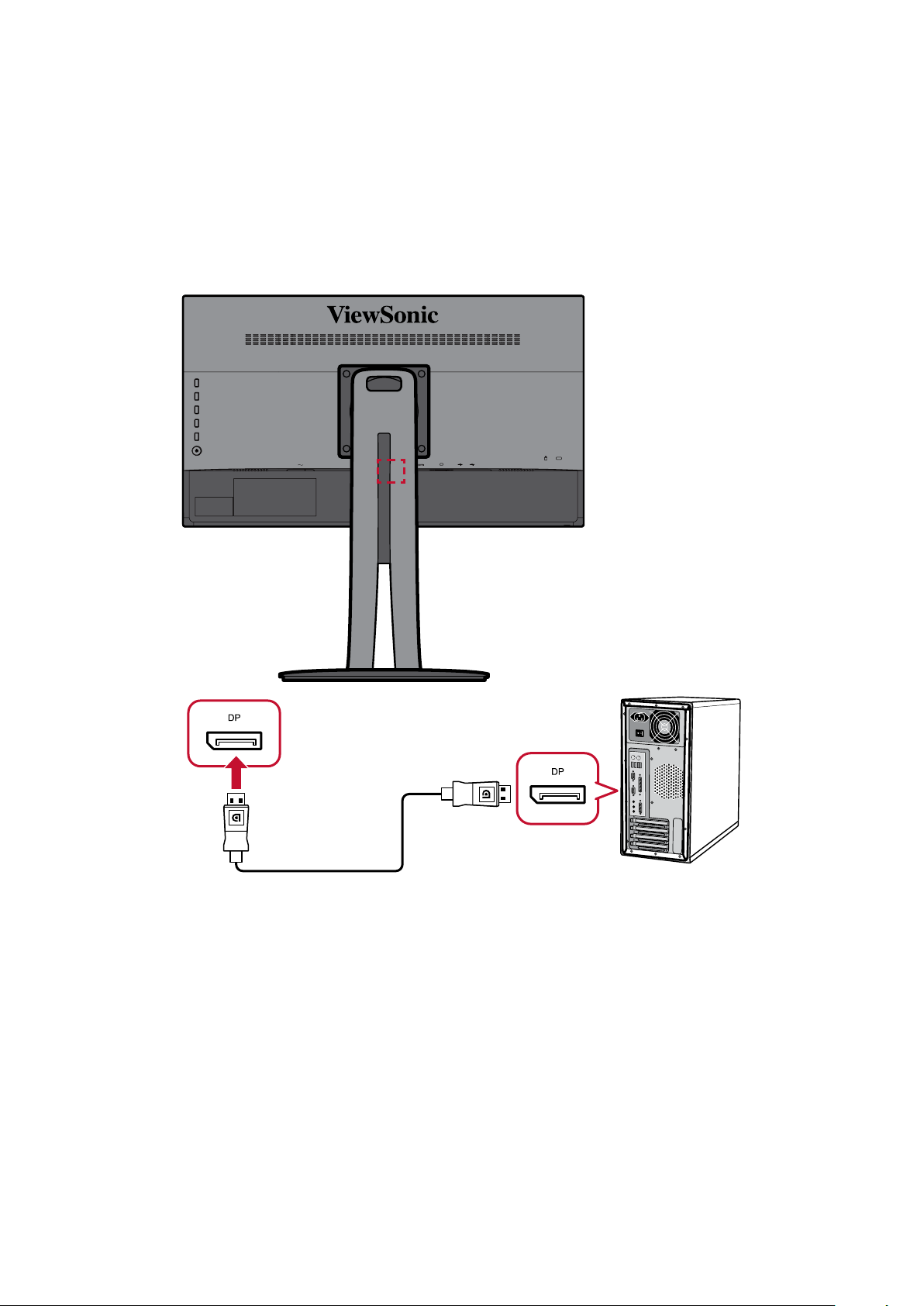
DisplayPort Connecon
Connect one end of a DisplayPort cable to the DisplayPort port. Then connect the
other end of the cable to the DisplayPort or mini DP port of your computer.
NOTE: To connect the monitor to the Thunderbolt port (v. 1&2) on your Mac,
connect the mini DP end of the “mini DP to DisplayPort cable” to the
Thunderbolt output of your Mac. Then connect the other end of the
cable to the DisplayPort of the monitor.
16
Page 17
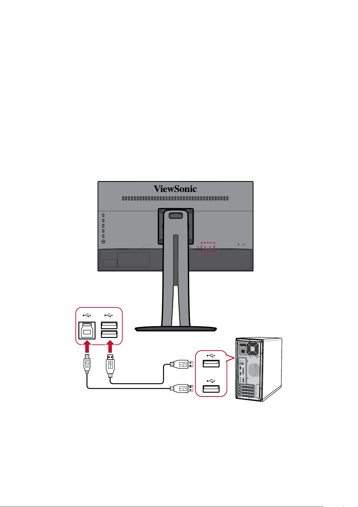
USB Connecon
Connect one end of a USB cable to a USB port of the monitor. Then connect the
other end of the cable to a USB port of your computer.
NOTE: The monitor supports two (2) types of USB ports. When making the
connecon(s), observe the following guidelines:
• Two (2) USB Type A ports: Connecon for your Type A peripheral
device(s). (i.e. storage device).
NOTE: To acvate the USB Type A port, ensure your computer is
also connected to the monitor’s USB Type B port.
• One (1) USB Type B port: Connect the USB Type B male cable (square
with 2 cut corners) to this port, and then connect the other end of the
cable to the USB downstream port of your computer.
17
Page 18
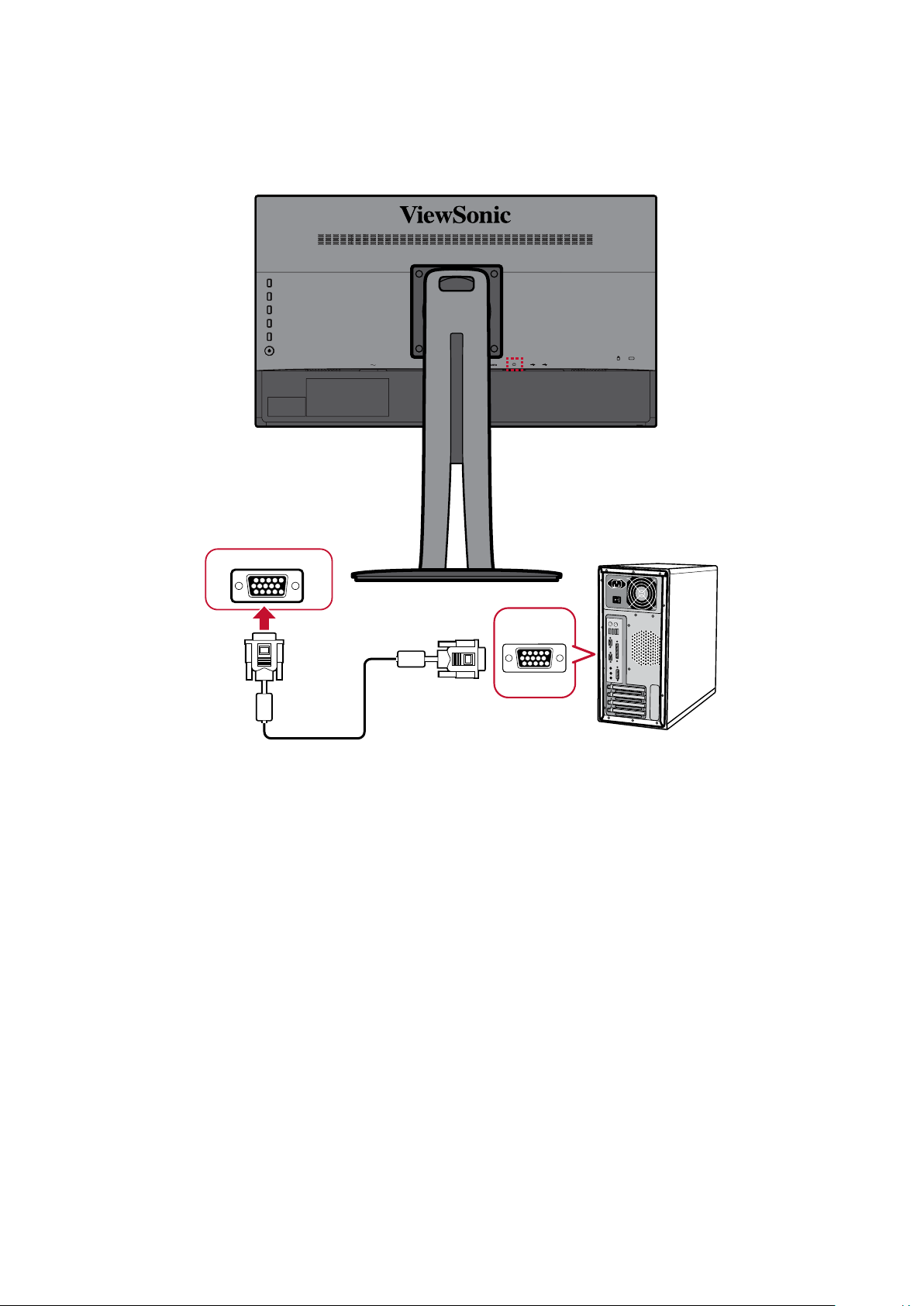
VGA Connecon
Connect one end of a VGA cable to the VGA port of your monitor. Then connect the
other end of the cable to the VGA port of your computer.
VGA
VGA
18
Page 19
Using the Monitor
Adjusng the Viewing Angle
For opmal viewing, you can adjust the viewing angle using any of the following
methods:
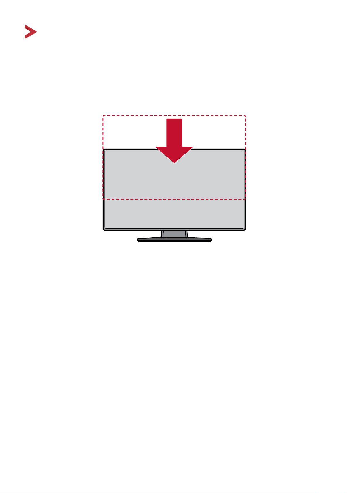
Height Adjustment
Lower or raise the monitor to the desired height (0 to 130 mm).
NOTE: When adjusng, press down rmly along the adjustment track holding
the monitor with both hands on the side.
19
Page 20
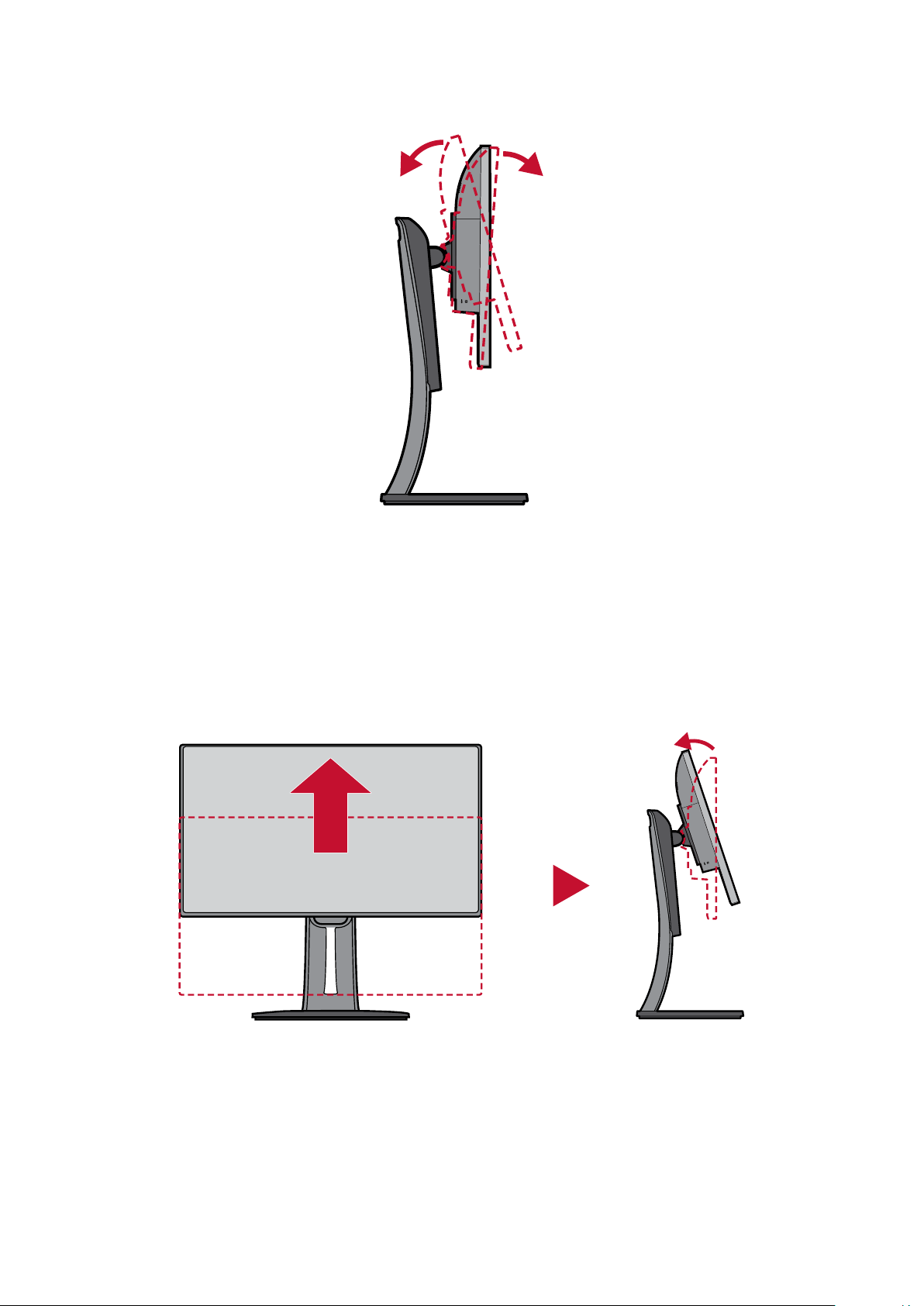
Tilt Angle Adjustment
Tilt the monitor forwards or backwards to the desired viewing angle (-5˚ to 21˚).
NOTE: When adjusng, support the stand rmly with one hand while lng the
monitor forwards or backwards with the other hand.
Screen Orientaon Adjustment (Monitor Pivot)
1. Adjust the monitor height to the highest posion. Then lt the monitor
backwards to the full lt posion.
20
Page 21
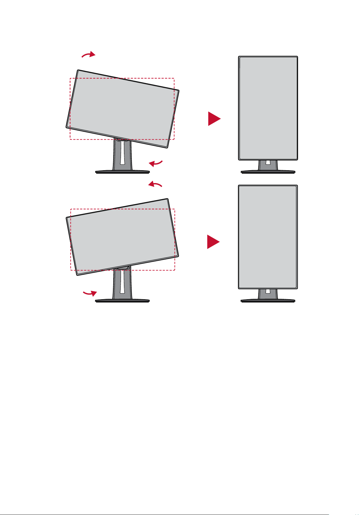
2. Rotate the monitor 90° clockwise or counter clockwise from landscape to portrait
orientaon.
NOTE:
• When adjusng, make sure to hold both sides of your monitor rmly with
both hands and rotate the monitor 90°.
• Using the “Auto Pivot” applicaon, the system can detect the screen
orientaon automacally.
21
Page 22
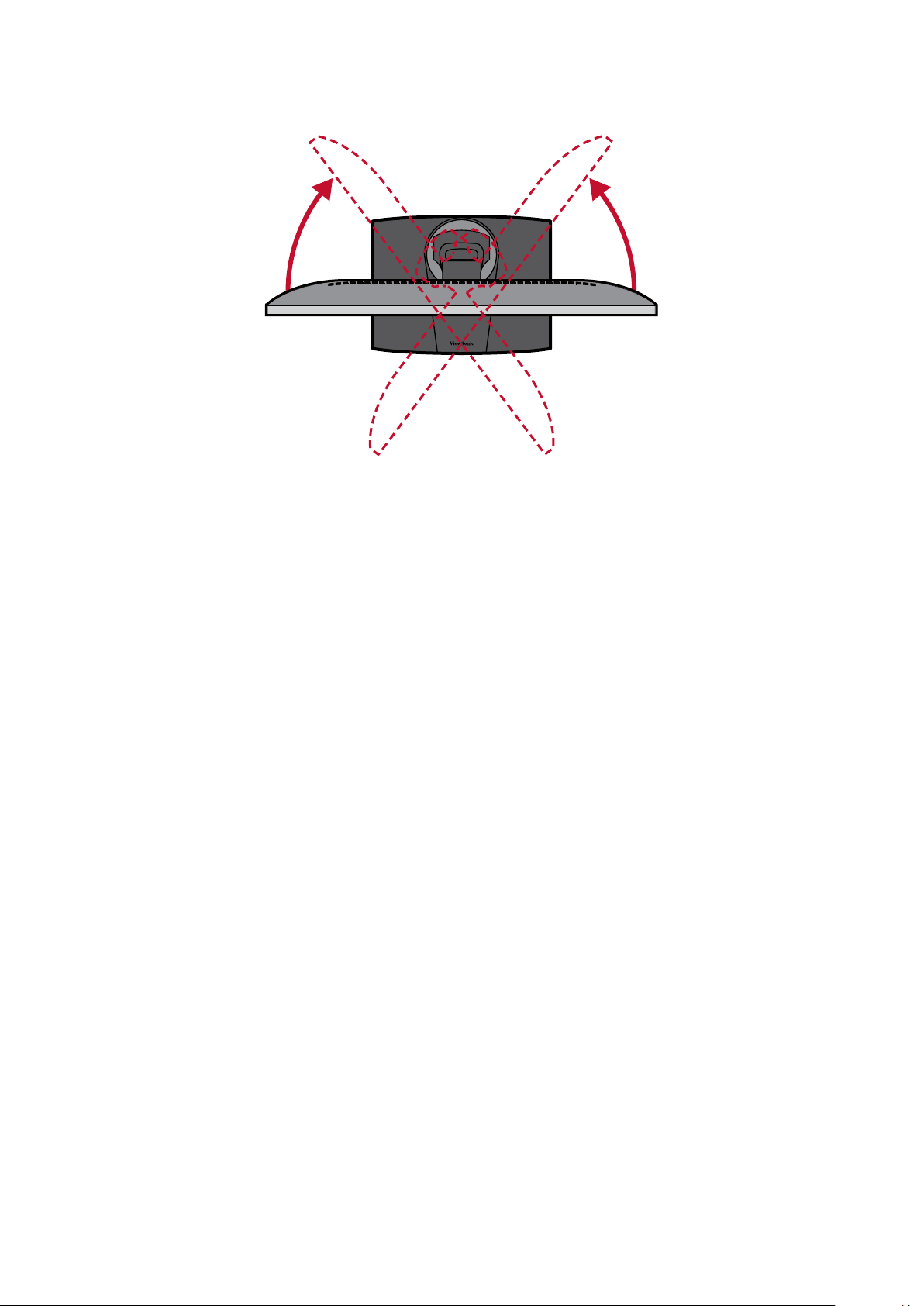
Swivel Angle Adjustment
Swivel the monitor to the le or right for the desired viewing angle (60˚).
22
Page 23
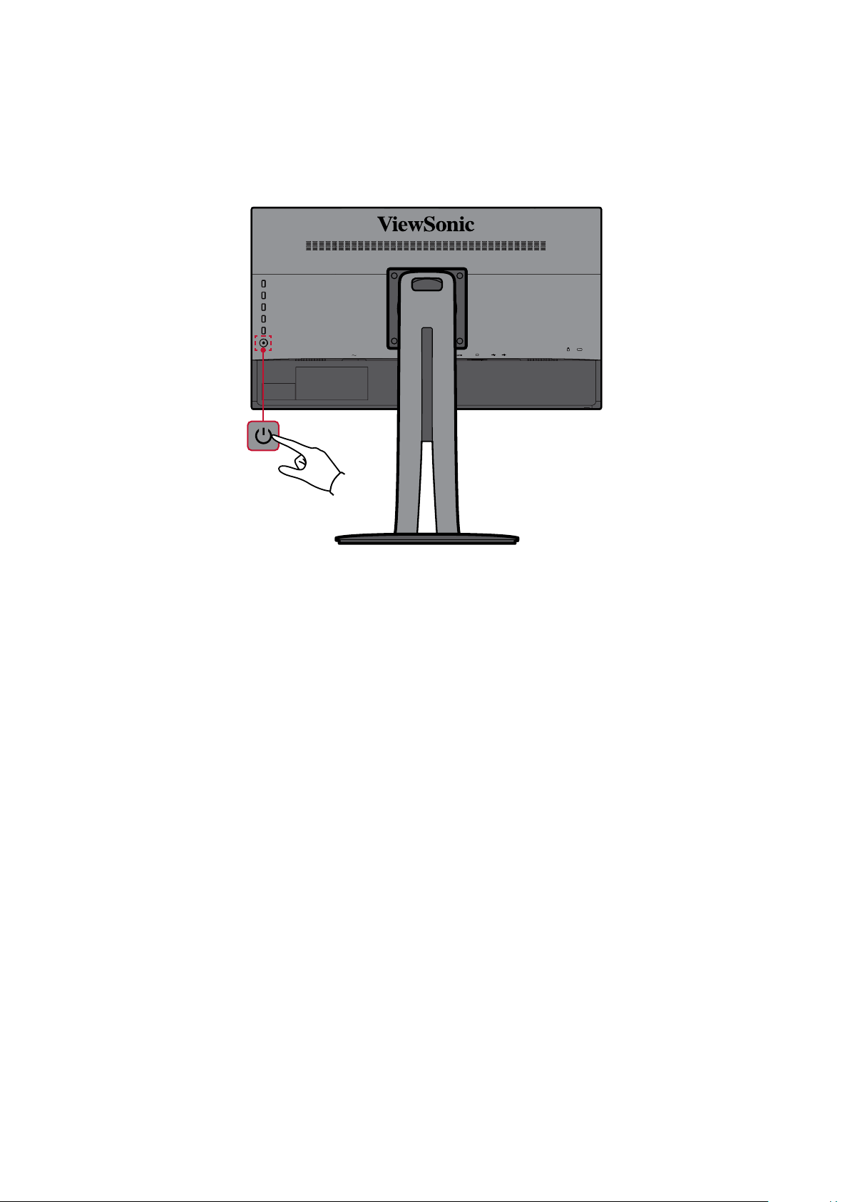
Turning the Device On/O
1. Plug the power cord into a power outlet.
2. Touch the Power buon to turn on the monitor.
3. To turn the monitor o, touch the Power buon again.
NOTE: The monitor will sll consume some power as long as the power cord
is connected to the power outlet. If the monitor is not being used for a
long period of me, please disconnect the power plug from the power
outlet.
23
Page 24

Using the Control Panel Keys
Use the control panel keys to access the Quick Menu, acvate Hot Keys, navigate
the On-Screen Display (OSD) Menu, and change the sengs.
1
2
3
4
5
Quick Menu
Press the 1/2/3/4 key to acvate the Quick Menu.
Standard Color
Contrast/Brightness
Input Select
Main Menu
Exit
NOTE: Follow the key guide that appears on the side of the screen to select the
opon or make adjustments.
Standard Color
Select one of the preset color sengs.
sRGB
CAL 1
CAL 2
CAL 3
Custom
24
Page 25

Contrast/Brightness
Adjust the contrast or brightness level.
Input Select
Select the input source.
Contrast
70
Brightness
100
DisplayPort
HDMI
D-Sub
Main Menu
Enter the On-Screen Display (OSD) Menu.
VP2458
Input
Select
DisplayPort
D-Sub
Auto Detect
HDMI
Color Adjust ViewMode
Exit
Manual Image
Adjust
Setup Menu
1920 X 1080@60HZ
Exit the Quick Menu.
NOTE: Use the 5 key to exit the Quick Menu.
25
Page 26

Hot Keys
When the On-Screen Display (OSD) Menu is o, you can quickly access special
funcons by using the control panel keys.
Key Descripon
1 Press and hold the key for 5 seconds to enter the “User Mode” menu.
Then select the desired user mode to acvate it.
User 1
User 2
User 3
Exit
5 Press the key to enable/disable the Blue Light Filter.
Blue Light Filter
On
NOTE: Viewing computer screens for extended periods of me may
cause eye irritaon and discomfort. To reduce these eects,
it is recommended to take periodic breaks from viewing to
allow the eyes to relax.
26
Page 27

Key Descripon
2 + 3 Press and hold the keys to lock/unlock the OSD Menu.
When the menu appears on the screen, connue holding both keys for
10 seconds to lock/unlock the OSD Menu.
OSD Lock/Unlock
Locking OSD
1
Press and hold for 10s
to lock OSD
If the OSD Menu is locked, the below message will appear on the
screen:
OSD Lock/Unlock
OSD Locked
27
Page 28

Key Descripon
2 + 4 Press and hold the keys to lock/unlock the Power buon.
When the menu appears on the screen, connue holding both keys for
10 seconds to lock/unlock the Power buon.
Power Lock/Unlock
Locking Power Button
3
Press and hold for 10s
to lock power
If the Power buon is locked, the below message will appear on the
screen:
Power Lock/Unlock
Power Button Locked
3 + 5 Press the keys to display/hide the boot up screen when the device is
turned on.
Boot Up Screen On/Off
Off
Press to turn on
28
Page 29

Conguring the Sengs
General Operaons
1. Press the 1/2/3/4 key to acvate the Quick Menu. Then press the 4 key to display
the On-Screen Display (OSD) Menu.
VP2458
Input
Select
DisplayPort
HDMI
D-Sub
Auto Detect
Color Adjust ViewMode
Manual Image
Adjust
Setup Menu
1920 X 1080@60HZ
2. Press the 1 or 2 key to select the main menu. Then press the 3 key to enter the
selected menu.
VP2458
Input
Select
Contrast/Brightness
Color Format
Standard Color
Custom
Color Calibration
Color Adjust ViewMode
Manual Image
Contrast
Brightness
Adjust
Setup Menu
1920 X 1080@60HZ
29
Page 30

3. Press the 1 or 2 key to select the desired menu opon. Then press the 3 key to
enter the sub-menu.
VP2458
Input
Select
Contrast/Brightness
Color Format
Standard Color
Custom
Color Calibration
Color Adjust ViewMode
Manual Image
Contrast
Brightness
Adjust
Setup Menu
1920 X 1080@60HZ
4. Press the 1 or 2 key to adjust/select the seng. Then press the 3 key to conrm.
VP2458
Input
Select
Color Adjust ViewMode
Manual Image
Adjust
Setup Menu
Contrast/Brightness
Color Format
Standard Color
Custom
Color Calibration
Contrast
Brightness
50
1920 X 1080@60HZ
30
Page 31

NOTE: Certain menu opon adjustments do not require the user to press the
3 key to conrm the selecon. Follow the key guide that appears on the
side of the screen to select the opon or make adjustments.
VP2458
Input
Select
Contrast/Brightness
Color Format
Standard Color
Custom
Color Calibration
Color Adjust ViewMode
Contrast
Brightness
Manual Image
Adjust
Setup Menu
1920 X 1080@60HZ
VP2458
Input
Select
Contrast/Brightness
Color Format
Standard Color
Custom
Color Calibration
Color Adjust ViewMode
Contrast
Brightness
Manual Image
Adjust
Setup Menu
1920 X 1080@60HZ
5. Press the 4 key to return to the previous menu.
NOTE: To exit the OSD Menu, press the 4 key unl the OSD Menu disappears.
50
Key GuideKey Guide
31
Page 32

On-Screen Display (OSD) Menu Tree
Main Menu Sub-menu Menu Opon
Input Select
ViewMode
DisplayPort
HDMI
D-Sub
Auto Detect On
O
O
Game FPS1
FPS2
RTS
MOBA
Movie
Web
Text
MAC Ultra Clear (-/+, 0~10)
Designer CAD/CAM Ultra Clear
Advanced-Sharpness
Advanced-Gamma
Animaon Ultra Clear
Advanced-Sharpness
Black Stabilizaon
Video Edit Ultra Clear
Advanced-Sharpness
Advanced-Gamma
32
Page 33

Main Menu Sub-menu Menu Opon
ViewMode
Photographer Retro Ultra Clear (-/+, 0~10)
Advanced-Sharpness (-/+, 0/25/50/75/100)
Advanced-Gamma (-/+,
1.8/2.0/2.2/2.4/2.6)
Photo Ultra Clear (-/+, 0~10)
Advanced-Sharpness (-/+, 0/25/50/75/100)
Advanced-Gamma (-/+,
1.8/2.0/2.2/2.4/2.6)
TruTone (-/+, 0~100)
Landscape Ultra Clear (-/+, 0~10)
Advanced-Sharpness (-/+, 0/25/50/75/100)
Advanced-Gamma (-/+,
1.8/2.0/2.2/2.4/2.6)
TruTone (-/+, 0~100)
Portrait Ultra Clear (-/+, 0~10)
Advanced-Sharpness (-/+, 0/25/50/75/100)
Advanced-Gamma (-/+, 1.8/2.0/2.2/
2.4/2.6)
TruTone (-/+, 0~100)
Skin Tone (-/+, 0~10)
Black Stabilizaon (-/+, 0~10)
Monochrome Advanced-Sharpness (-/+, 0/25/50/75/100)
TruTone (-/+, 0~100)
33
Page 34

Main Menu Sub-menu Menu Opon
Color Adjust
Contrast/
Brightness
Color Format Auto
Standard
Color
Custom Color Temperature Panel Default
Contrast (-/+, 0~100)
Brightness (-/+, 0~100)
RGB (Full Range)
RGB (Limited
Range)
YUV (Full Range)
YUV (Limited
Range)
sRGB
Bluish 9300K
Cool 7500K
Nave 6500K
Warm 5000K
User
Gamma O
1.8
2.0
2.2
2.4
2.6
Black Stabilizaon (-/+, 0~10)
Advanced DCR (-/+, 0/25/50/75/ 100)
Gain Red (-/+, 0~100)
Green (-/+, 0~100)
Blue (-/+, 0~100)
Oset Red (-/+, 0~100)
Green (-/+, 0~100)
Blue (-/+, 0~100)
Hue Red (-/+, 0~100)
Green (-/+, 0~100)
Blue (-/+, 0~100)
Cyan (-/+, 0~100)
Magenta (-/+, 0~100)
Yellow (-/+, 0~100)
34
Page 35

Main Menu Sub-menu Menu Opon
Color Adjust
Manual
Image Adjust
Custom Saturaon Red (-/+, 0~100)
Green (-/+, 0~100)
Blue (-/+, 0~100)
Cyan (-/+, 0~100)
Magenta (-/+, 0~100)
Yellow (-/+, 0~100)
Recall
Color
Calibraon
Auto Image Adjust
Horizontal
Size
CAL 1
CAL 2
CAL 3
Calibraon Noce Remind Schedule (-/+, 0/1/10/100/200/
500/1000/2000/3000)
Counter Hour
Recall
(-/+, 0~100)
H./V. Posion Horizontal Posion (-/+, 0~100)
Vercal Posion (-/+, 0~100)
Fine Tune (-/+, 0~100)
Sharpness (-/+, 0~100)
Aspect Rao 4:3
Full Screen
Overscan On
O
Low Input Lag On
O
Response
Time
Blue Light
Filter
Standard
Advanced
Ultra Fast
(-/+, 0~100)
35
Page 36

Main Menu Sub-menu Menu Opon
Setup Menu
Language English
Français
Deutsch
Español
Italiano
Suomi
Русский
Türkçe
日本語
한국어
繁體中文
简体中文
Česká
Svenska
Resoluon
Noce
On
O
Informaon
OSD Timeout (-/+, 5/15/30/60)
OSD
Background
OSD Pivot Auto
Power
Indicator
Auto Power
O
Sleep 30 Minutes
On
O
0˚
+90˚
-90˚
On
O
On
O
45 Minutes
60 Minutes
120 Minutes
O
36
Page 37

Main Menu Sub-menu Menu Opon
Setup Menu
Eco Mode Standard
Opmize
Conserve
USB Charging On
DisplayPort
1.1
DDC/CI On
Save As User 1
All Recall
On
O
O
User 2
User 3
Recall
O
37
Page 38

Menu Opons
Input Select
1. Press the 1/2/3/4 key to display the Quick Menu. Then press the 4 key to display
the OSD Menu.
2. Press the 1 or 2 key to select Input Select. Then press the 3 key to enter the Input
Select menu.
VP2458
Input
Select
DisplayPort
HDMI
D-Sub
Auto Detect
Color Adjust ViewMode
Manual Image
Adjust
Setup Menu
1920 X 1080@60HZ
3. Press the 1 or 2 key to select the desired input source. Then press the 3 key to
conrm the selecon.
38
Page 39

ViewMode Menu
NOTE: When a ViewMode is selected, the 5 key acvates the Quick Menu.
1. Press the 1/2/3/4 key to display the Quick Menu. Then press the 4 key to display
the OSD Menu.
2. Press the 1 or 2 key to select ViewMode. Then press the 3 key to enter the
ViewMode menu.
VP2458
Input
Select
Off
Game
Movie
Web
Text
MAC
Designer
Photographer
Color Adjust ViewMode
Manual Image
Adjust
Setup Menu
1920 X 1080@60HZ
3. Press the 1 or 2 key to select the seng. Then press the 3 key to conrm the
selecon.
Menu Opon Descripon
O Disable the funcon.
Game Select this opon for playing games.
Movie Select this opon for watching movies.
Web Select this opon for surng the web.
Text Select this opon for text-based tasks.
MAC Select this opon when connecng to Mac computers.
Designer Select this opon for viewing graphic design les.
Photographer Select this opon for viewing photo les.
39
Page 40

Color Adjust Menu
NOTE: Some sub-menus may not be adjustable depending on the user’s custom
sengs.
1. Press the 1/2/3/4 key to display the Quick Menu. Then press the 4 key to display
the OSD Menu.
2. Press the 1 or 2 key to select Color Adjust. Then press the 3 key to enter the
Color Adjust menu.
VP2458
Input
Select
Contrast/Brightness
Color Format
Standard Color
Custom
Color Calibration
Color Adjust ViewMode
Manual Image
Adjust
Setup Menu
1920 X 1080@60HZ
3. Press the 1 or 2 key to select the menu opon. Then press the 3 key to enter its
sub-menu.
4. Press the 1 or 2 key to select the seng. Then press the 3 key to conrm the
selecon.
NOTE: Some sub-menu opons may have another sub-menu. To enter the
respecve sub-menu, press the 3 key. Follow the key guide that appears
on the side of the screen to select the opon or make adjustments.
Menu Opon Descripon
Contrast/
Brightness
Contrast
Adjust the degree of dierence between the lightest and
darkest parts of the picture and change the amount of black
and white in the image.
Brightness
Adjust the background black levels of the screen image.
40
Page 41

Menu Opon Descripon
Color Format The monitor can detect the input signal color range
automacally. You can manually change the color range
opons to t the correct color range if the colors are not
displayed correctly.
• Auto: Automacally recognizes the color format and black
and white levels.
• RGB (Full Range): The input signal color format is RGB and
the black and white levels are full.
• RGB (Limited Range): The input signal color format is RGB
and the black and white levels are limited.
• YUV (Full Range): The input signal color format is YUV and
the black and white levels are full.
• YUV (Limited Range): The input signal color format is YUV
and the black and white levels are limited.
Standard Color The monitor comes with several display industry color
standards. Each color mode can be selected for applicaons of
the monitor.
• sRGB: Precise color gamut and gamma of sRGB standard.
Custom
Color Temperature
Select the color temperature seng.
• Panel Default: Use the default sengs of the monitor.
• Bluish: Set the color temperature to 9300K.
• Cool: Set the color temperature to 7500K
• Nave: Default color temperature. Recommended for
regular use.
• Warm: Set the color temperature to 5000K.
• User Color: Adjust red, green, and blue values as desired.
41
Page 42

Menu Opon Descripon
Custom
Gamma
Manually adjust the brightness level of the monitor’s
grayscale levels.
Black Stabilizaon
Provide heightened visibility and detail by brightening dark
scenes.
Advanced DCR
Automacally detects the image signal and intelligently
controls the backlight brightness and color, to improve on the
ability to make the black blacker in a dark scene, and make
the white whiter in a bright environment.
Gain
Adjust white temperature to customize your USER COLOR (can
be saved in User Mode) or a specic color temperature and
gain value (red, green, blue).
Oset
Adjust black levels for red, green, and blue.
The gain and oset funcons allow users to control the white
balance for the upmost control when manipulang contrast
and dark scenes.
Hue
Adjust the nt of each color (red, green, blue, cyan, magenta,
and yellow).
Saturaon
Adjust the color depth of each color (red, green, blue, cyan,
magenta, and yellow).
Recall
Restore custom related sengs to default.
42
Page 43

Menu Opon Descripon
Color Calibraon
(Калибриране на
цветовете)
Калибрирайте монитора с помощта на приложението
ViewSonic® Colorbraon със специфични цветови датчици.
• CAL 1: Дисплей с режима на калибриране на първия
потребител.
• CAL 2: Дисплей с режима на калибриране на втория
потребител.
• CAL 3: Дисплей с режима на калибриране на третия
потребител.
• Color Calibraon Noce (Съобщение за калибриране
на цветовете): Конфигурирайте настройките на
съобщението за калибриране.
Reminder Schedule Hour (Напомняне за час от
графика) Задайте график за съобщението за
калибриране.
Counter Hour (Брояч на часове): Покажете
натрупаното време от последното калибриране.
• Recall (Повторно извикване): Нулирайте настройките,
свързани с Color Calibraon (Калибриране на
цветовете) на стойностите им по подразбиране.
43
Page 44
Manual Image Adjust Menu
1. Press the 1/2/3/4 key to display the Quick Menu. Then press the 4 key to display
the OSD Menu.
2. Press the 1 or 2 key to select Manual Image Adjust. Then press the 3 key to enter
the Manual Image Adjust menu.
VP2458
Input
Select
Auto Image Adjust
Horizontal Size
H./V. Position
Fine Tune
Sharpness
Aspect Ratio
Overscan
Low Input Lag
Response Time
Blue Light Filter
Color Adjust ViewMode
Manual Image
Adjust
Setup Menu
1920 X 1080@60HZ
3. Press the 1 or 2 key to select the menu opon. Then press the 3 key to enter its
sub-menu.
4. Press the 1 or 2 key to adjust/select the seng. Then press the 3 key to conrm
(if applicable).
Menu Opon Descripon
Auto Image Adjust Automacally adjust the screen image posion.
Horizontal Size Stretch or shorten the screen on its horizontal axis.
H./V. Posion Adjust the screen horizontally and/or vercally.
Fine Tune Improve distorted image quality from an analog signal.
Sharpness Adjust the picture quality.
Aspect Rao Select the aspect rao of the monitor.
Overscan Automacally enlarge the original picture horizontally and
vercally to an equal aspect rao that lls the screen.
Low Input Lag Select the appropriate speed to decrease input to output
latency.
44
Page 45

Menu Opon Descripon
Response Time Adjust the response me, creang smooth images without
streaking, blurring or ghosng. A low response me is perfect
for the most graphic-intense gaming, and provides amazing
visual quality while watching sports or acon movies.
Blue Light Filter Adjust the lter that blocks high-energy blue light for a more
comfortable viewing experience.
45
Page 46

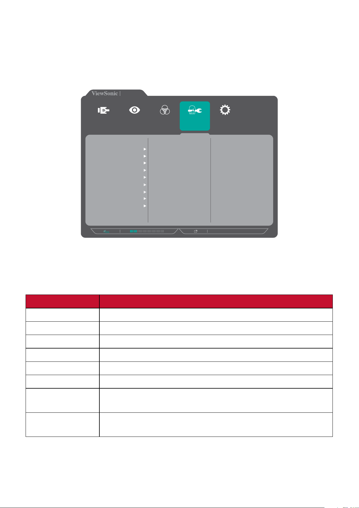
Setup Menu
1. Press the 1/2/3/4 key to acvate the Quick Menu. Then press the 4 key to display
the OSD Menu.
2. Press the 1 or 2 key to select Setup Menu. Then press the 3 key to enter the
Setup Menu menu.
VP2458
Input
Select
Language Select
Resolution Notice
Information
OSD Timeout
OSD Background
OSD Pivot
Power Indicator
Auto Power Off
Sleep
ECO Mode
DisplayPort 1.1
Color Adjust ViewMode
Manual Image
Adjust
Setup Menu
1920 X 1080@60HZ
3. Press the 1 or 2 key to select the menu opon. Then press the 3 key to enter its
sub-menu.
4. Press the 1 or 2 key to select the seng. Then press the 3 key to conrm the
selecon.
NOTE: Some sub-menu opons may have another sub-menu. To enter the
respecve sub-menu, press the 3 key. Follow the key guide that appears
on the side of the screen to select the opon or make adjustments.
46
Page 47

Menu Opon Descripon
Language Select Select an available language for the OSD Menu.
Resoluon Noce Enable this opon to allow the system to inform users that
the current viewing resoluon is not the correct nave
resoluon.
Resolution Notice
For best picture quality,
change resolution to 1920x1080
Clear
Message
Disable
Message
Press the 1 key to hide the message or press the 3 key to
disable this funcon.
Informaon Display the monitor’s informaon.
OSD Timeout Set the length of me the OSD Menu remains on the screen.
OSD Background Show/Hide the OSD background when the OSD Menu appears
on the screen.
OSD Pivot Set the OSD Menu orientaon.
• Auto: With built-in G sensor, the OSD Menu can auto pivot
when the monitor is posioned vercally.
• 0 °: Sets the OSD Menu without pivot.
• +90 °: Sets the OSD Menu with a +90 ° pivot.
• -90 °: Sets the OSD Menu with a -90 ° pivot.
Power Indicator Set the power indicator On or O. If the seng is set to On,
the power indicator lights blue when the device is turned on.
Auto Power O Enable this opon to allow the monitor to automacally turn
o aer a certain amount of me.
Sleep
Set the amount of idle me before the monitor enters Sleep
mode.
ECO Mode Choose between various modes, based on power
consumpon.
DisplayPort 1.1 Enable/Disable DisplayPort 1.1 support.
47
Page 48

Menu Opon Descripon
DDC/CI Enable this opon to allow the monitor control via the
graphics card.
Save As Set the personalized OSD conguraons for User 1/User 2/
User 3.
All Recall Resets all sengs to their default values.
48
Page 49

Advanced Features and Sengs
This secon describes advanced features of the monitor.
Colorbraon
To ensure long-term color accuracy, some specific models support hardware color
calibration function. The monitor comes with the Colorbration application. The
application installation file is in the software folder of the ViewSonic® CD. Or you
can visit: hp://color.viewsonic.com/support/soware/ to check and download the
latest version of the Colorbration application.
Standard monitor packing does not include the color sensor, which the Colorbration
application needs for the calibration process.
However, if you purchased our ViewSonic®’s Colorbration kit, it includes the
CSXRi1 color sensor, which has been co-developed with X-Rite to provide the best
solution for displaying long-term color accuracy. CS-XRi1 is X-Rite’s next generation
colorimeter, which utilizes a redesigned optical system, filter technology, calibration
architecture, and intelligent form factor to be paired with ViewSonic®’s Colorbration
application to deliver unrivalled color accuracy, repeatability, and device longevity.
NOTE: Best with ViewSonic® CS-XRi1, compatible with X-Rite i1Display Pro and
i1 Pro 2.
49
Page 50

Auto Pivot
With the Auto Pivot funcon, the monitor can detect the image display and adjust
the image’s orientaon on the screen automacally when pivong the screen
vercally or horizontally.
The applicaon installaon le is in the soware folder of the ViewSonic® CD. Or
you can visit: hp://color.viewsonic.com/support/soware/ to check and download
the latest version of the Auto Pivot applicaon.
NOTE: The Auto Pivot funcon uses DDC/CI to communicate with the monitor.
Before applying the Auto Pivot funcon, please make sure the DDC/CI
seng is set to On.
To enable the DDC/CI seng, do the following:
1. Open the OSD Menu and select the Setup Menu menu. Then press the 3 key to
enter the menu.
2. Press the 1 or 2 key to select DDC/CI. Then press the 3 key to enter its sub-menu.
3. Press the 1 or 2 key to select On. Then press the 3 key to conrm.
VP2458
Input
Select
Color Adjust ViewMode
DDC/CI
Save As
All Recall
Manual Image
On
Off
Adjust
Setup Menu
1920 X 1080@60HZ
50
Page 51

Firmware Update
For the best display performance and to resolve any known issues, it is best to keep
your monitor updated with the latest rmware version. With the USB cable and
rmware update tool, you can easily update your monitor rmware any me.
You can visit: hps://color.viewsonic.com/support/soware/ to check and
download the latest rmware version with the update tool.
To update the rmware, do the following:
1. Check and download the Firmware Update Tool with the latest rmware version
for your monitor from: hp://color.viewsonic.com/support/soware/.
2. Connect the USB Type B male cable (square with 2 cut corners) to the USB Type B
port of your monitor. Then connect the other end of the cable to the USB port of
your computer.
3. Unzip the downloaded Firmware Update Tool and double-click on the .exe le
or .pkg le. Then follow the on-screen instrucons to complete the applicaon
installaon.
4. Launch the Firmware Update Tool. The applicaon will automacally detect and
verify your monitor model and current rmware version.
5. Click Update to upgrade your monitor rmware, and wait unl the upgrade
process is complete.
51
Page 52

VP Series USB Firmware Update Tool v1.0
Model Name
Current Firmware
New Firmware
CheckSum
Model Name
Current Firmware
New Firmware
CheckSum
0%
Update EXIT(X)
CAUTION: Any interrupons during the rmware upgrade process may
permanently damage your monitor. Do not disconnect the USB cable or
turn o your PC and monitor.
52
Page 53

Appendix
Specicaons
Item Category Specicaons
LCD Type IPS, Acve Matrix 1920 X 1080 LCD;
0.2745 (H)mm x 0.2745(V)mm pixel pitch
Display Size 60.47 cm, 24" (23.8” viewable)
Color Filter RGB vercal stripe
Glass Surface An-Glare type, 3H hard coang
Input Signal Video Sync TMDS digital (100 Ω)
:55-90 Khz, fv:48-75 hz
f
h
Compability PC Up to 1920 x 1080
Macintosh Up to 1920 x 1080
Recommended 1920 x 1080 @ 60Hz
Resoluon
Power
Display area Full Scan (H x V) 527.04 x 296.46 mm (20.75” x 11.67”)
Operang
condions
Storage
condions
1
2
Supported 1920 x 1080 @ 60Hz
1680 x 1050 @60Hz
1440 x 900 @ 60Hz
1280 x 1440 @ 60Hz
1280 x 1024 @ 60, 75Hz
1024 x 768 @ 60, 70, 75Hz
800 x 600 @ 56, 60, 72, 75Hz
720 x 400 @ 70Hz
640 x 480 @ 60, 72, 75Hz
Input Voltage AC 100-240V, 50/60 Hz (auto switch)
Temperature 0°C to 40°C (32°F to 104°F)
Humidity 20% to 90% (non-condensing)
Altude Up to 16,404 feet (4.9 km)
Temperature -20°C to 60°C (-4°F to 140°F)
Humidity 5% to 90% (non-condensing)
Altude To 40,000 feet (12 km)
Dimensions Physical
(W x H x D)
Wall Mount Dimensions 100 x 100 mm
Weight Physical 5.7 kg (12.54 lbs)
538.67 x 521.57 x 215 mm
(21.21” x 20.53” x 8.46”)
53
Page 54

Item Category Specicaons
Power saving
modes
1
Do not set the graphics card in your computer to exceed these ming modes; doing so may result in
permanent damage to the display.
2
Please use the power adapter from ViewSonic® or an authorized source only.
3
The test condion follows EEI standard.
3
On
17.5W (Typical) (Blue LED)
O < 0.3W
54
Page 55

Glossary
This secon describes the standard glossary of terms used in all LCD display models.
All terms are listed in alphabecal order.
NOTE: Some terms may not be applicable to your device.
A
B
Advanced DCR
Advanced DCR technology automacally detects the image signal and
intelligently controls the backlight brightness and color, to improve on the
ability to make the black blacker in a dark scene, and make the white whiter
in a bright environment.
Auto Detect
If the current input source has no signal, the monitor will automacally
switch to the next input opon. This funcon on some models is disabled by
default.
Black Stabilizaon
ViewSonic’s Black stabilizaon provides heightened visibility and detail by
brightening dark scenes.
Blue Light Filter
Adjusts the lter that blocks high-energy blue light for a more comfortable
viewing experience.
Brightness
Adjusts background black levels of the screen image.
55
Page 56

C
Color Adjust
Provides several color adjustment modes, to help adjust the color sengs to
t the user’s needs.
Color Format
The monitor can detect the input signal color format automacally. You can
manually change the color format opons to t the correct color format
range if the colors are not displayed correctly.
Opons Descripon
Auto The monitor automacally recognizes the color format
and the black and white levels.
RGB
(Full Range)
RGB
(Limited Range)
YUV
(Full Range)
YUV
(Limited Range)
Color Space
Allows users to choose which color space they would like to use for monitor
color output (RGB, YUV).
Color Temperature
Allows users to select specic color temperature sengs to further
customize their viewing experience.
Panel Default Panel original status
The input signal color format is RGB and the black and
white levels are full.
The input signal color format is RGB and the black and
white levels are limited.
The input signal color format is YUV and the black and
white levels are full.
The input signal color format is YUV and the black and
white levels are limited.
sRGB Standard color space used for the Windows system.
Bluish Set the color temperature to 9300K.
Cool Set the color temperature to 7500K.
Nave Default color temperature. Recommended for general use.
Warm Set the color temperature to 5000K.
Contrast
Adjusts the dierence between the image background (black level) and the
foreground (white level).
56
Page 57

G
Gain
Adjusts the white temperature to customize your USER COLOR, which can
be saved in “User Mode”, or a specic color temperature and gain value
(red, green, and blue).
Game Mode
Integrang a gaming-oriented OSD design including pre-calibrated FPS,
RTS, and MOBA gaming sengs. Each mode is funconally customized
with in-game tesng and adjustments made for the best blend of color and
technology.
Gamma
Allows users to manually adjust the brightness level of the monitor’s
grayscale levels.
H
I
Hue
Adjusts the nt of each color (red, green, blue, cyan, magenta, and yellow).
Informaon
Displays the ming mode (video signal input) coming from the graphics
card in the computer, the LCD model number, the serial number, and
the ViewSonic® website URL. See your graphics cards’s user guide for
instrucons on changing the resoluon and refresh rate (vercal frequency).
NOTE: VESA 1024 x 768 @ 60Hz, for example, means that the resoluon
is 1024 x 768 and the refresh rate is 60Hz.
Input Select
Toggles between the various input opons that are available for the
monitor.
L
Low Input Lag
ViewSonic® oers low input lag, ulizing a monitor process reducer, which
decreases signal latency. Under the “Low Input Lag” sub-menu, you can
select the appropriate speed for your desired use from the two opons.
57
Page 58

M
Manual Image Adjust
Displays the “Manual Image Adjust” menu. You can manually set a variety of
image quality adjustments.
Memory Recall
Returns the adjustments back to factory sengs if the display is operang in
a factory preset ming mode listed in the “Specicaons” of this manual.
NOTE: (Excepon) This control does not aect changes made in the
“Language Select” or “Power Lock Seng”.
O
Oset
Adjusts black levels for red, green, and blue. The gain and oset funcons
allow users to control the white balance for the upmost control when
manipulang contrast and dark scenes.
OSD Pivot
Sets the monitor OSD Menu display direcon.
Opons Descripon
Auto With a built-in G sensor, the OSD can auto pivot when
posioned vercally.
0° Sets the OSD Menu without a pivot.
+90° Sets the OSD Menu with a +90° pivot.
-90° Sets the OSD Menu with a -90° pivot.
Overscan
Refers to a cropped image on your monitor’s screen. A seng on your
monitor zooms in on movie content, so that you can’t see the outermost
edges of the lm.
58
Page 59

R
Recall
Resets the ViewMode monitor sengs.
Resoluon Noce
The noce tells users that the current viewing resoluon is not the correct
nave resoluon. This noce will appear in the display sengs window
when seng up the display resoluon.
Response Time
Adjusts the response me, creang smooth images without streaking,
blurring or ghosng. A low response me is perfect for the most graphic-
intense gaming, and provides amazing visual quality while watching sports
or acon movies.
S
Saturaon
Adjusts the color depth of each color (red, green, blue, cyan, magenta, and
yellow).
Save As
The OSD save funcon is located in the main menu. There are proles which
allows the user to save their OSD sengs.
Setup Menu
Adjusts On-Screen Display (OSD) Menu sengs. Many of these sengs can
acvate on-screen display nocaons so users do not have to reopen the
menu.
Sharpness
Adjusts the picture quality of the monitor.
Standard Color
The monitor comes with several display industry color standards. Each color
mode can be selected for specic monitor applicaons.
V
Opons Descripon
sRGB Precise color gamut and gamma of sRGB standard.
Nave Original color presented by the LCD panel.
ViewMode
ViewSonic’s unique ViewMode feature oers “Standard”, “FPS Game”,
“RTS Game”, “MOBA Game”, “Movie”, “Web”, “Text”, “MAC”, and “Mono”
presets. These presets are specically designed to deliver an opmized
viewing experience for dierent screen applicaons.
59
Page 60

Troubleshoong
This secon describes some common problems that you may experience when
using the monitor.
Problem or Issue Possible Soluons
No power • Make sure you have turned on the monitor.
Otherwise, touch the Power buon to turn on the
monitor.
• Make sure the power cord is properly and securely
connected to the monitor.
• Plug another electrical device into the power outlet to
verify that the outlet is supplying power.
Power is On, but no
image appears on the
screen
Wrong or abnormal
colors
Screen image is too
light or dark
• Make sure the video cable connecng the monitor to
the computer is properly and securely connected.
• Check for broken pins in the video cable connector.
• Adjust the brightness and contrast sengs.
• Make sure the correct input source is selected.
• If any colors (red, green, or blue) are missing, check
the video cable to make sure it is properly and
securely connected. Loose or broken pins in the cable
connector could cause an improper connecon.
• Connect the monitor to another computer.
• If you have an older graphics card, contact ViewSonic®
for a non-DDC adapter.
• Adjust brightness and contrast sengs via the OSD
Menu.
• Reset the monitor to factory sengs.
Screen image cuts in
and out
Screen image or text is
blurred
• Make sure the correct input source is selected.
• Check for bent or broken pins in the video cable
connector.
• Make sure the video cable connecng the monitor to
the computer is properly and securely connected.
• Adjust the resoluon to the correct Aspect Rao.
• Reset the monitor to factory sengs.
60
Page 61

Problem or Issue Possible Soluons
The screen isn’t
centered correctly
The screen appears
yellow
The OSD Menu
does not appear
on the screen/the
OSD controls are
inaccessible
Control panel keys do
not work
Some menus aren’t
selectable in the OSD
• Adjust the horizontal and vercal controls via the OSD
Menu.
• Check the Aspect Rao.
• Reset the monitor to factory sengs.
• Make sure the “Blue Light Filter” is O.
• Check whether the OSD Menu is locked. If yes, press
and hold the 2 and 3 key for 10 seconds.
• Turn o the monitor, unplug the power cord, plug it
back in, and then turn on the monitor.
• Reset the monitor to factory sengs.
• Press only one key at a me.
• Restart the computer.
• Adjust the ViewMode or the input source.
• Reset the monitor to factory sengs.
The monitor will not
adjust
USB devices connected
to the monitor do not
work
The external device
is connected, but no
image appears on the
screen
• Make sure there are no obstrucons near or on the
monitor, and that there is adequate spacing.
• Make sure the USB cable is connected properly.
• Try changing to another USB port (if applicable).
• Some USB devices require a higher electric current;
connect the device directly to the computer.
• Make sure the Power is On
• Adjust brightness and contrast via the OSD Menu.
• Check the connecng cable and make sure it is
properly and securely connected. Loose or broken
pins in the cable connector could cause an improper
connecon.
61
Page 62

Maintenance
General Precauons
• Make sure the monitor is turned o and the power cable is unplugged from the
power outlet.
• Never spray or pour any liquid directly onto the screen or case.
• Handle the monitor with care, as a darker-colored monitor, if scued, may show
marks more clearly than a lighter-colored monitor.
Cleaning the Screen
• Wipe the screen with a clean, so, lint-free cloth. This removes dust and other
parcles.
• If the screen is sll not clean, apply a small amount of non-ammonia, nonalcohol based glass cleaner onto a clean, so, lint-free cloth; then wipe the
screen.
Cleaning the Case
• Use a so, dry cloth.
• If the case is sll not clean, apply a small amount of a non-ammonia, non-alcohol
based, mild non-abrasive detergent onto a clean, so, lint-free cloth, then wipe
the surface.
Disclaimer
• ViewSonic® does not recommend the use of any ammonia or alcohol-based
cleaners on the display screen or case. Some chemical cleaners have been
reported to damage the screen and/or case of the monitor.
• ViewSonic® will not be liable for damage resulng from use of any ammonia or
alcohol-based cleaners.
62
Page 63

Regulatory and Service Information
Compliance Information
This section addresses all connected requirements and statements regarding
regulations. Confirmed corresponding applications shall refer to nameplate labels
and relevant markings on the unit.
FCC Compliance Statement
This device complies with part 15 of FCC Rules. Operation is subject to the following
two conditions: (1) this device may not cause harmful interference, and (2) this
device must accept any interference received, including interference that may
cause undesired operation. This equipment has been tested and found to comply
with the limits for a Class B digital device, pursuant to part 15 of the FCC Rules.
These limits are designed to provide reasonable protection against harmful
interference in a residential installation. This equipment generates, uses, and
can radiate radio frequency energy, and if not installed and used in accordance
with the instructions, may cause harmful interference to radio communications.
However, there is no guarantee that interference will not occur in a particular
installation. If this equipment does cause harmful interference to radio or television
reception, which can be determined by turning the equipment off and on, the user
is encouraged to try to correct the interference by one or more of the following
measures:
• Reorient or relocate the receiving antenna.
• Increase the separation between the equipment and receiver.
• Connect the equipment into an outlet on a circuit different from that to which
the receiver is connected.
• Consult the dealer or an experienced radio/TV technician for help.
Warning: You are cautioned that changes or modifications not expressly approved
by the party responsible for compliance could void your authority to operate the
equipment.
Industry Canada Statement
CAN ICES-3 (B)/NMB-3(B)
63
Page 64

CE Conformity for European Countries
The device complies with the EMC Directive 2014/30/EU and Low Voltage
Directive 2014/35/EU.
The following information is only for EU-member states:
The mark shown to the right is in compliance with the Waste Electrical
and Electronic Equipment Directive 2012/19/EU (WEEE). The mark
indicates the requirement NOT to dispose of the equipment as unsorted
municipal waste, but use the return and collection systems according to
local law.
Declaration of RoHS2 Compliance
This product has been designed and manufactured in compliance with Directive
2011/65/EU of the European Parliament and the Council on restriction of the use
of certain hazardous substances in electrical and electronic equipment (RoHS2
Directive) and is deemed to comply with the maximum concentration values issued
by the European Technical Adaptation Committee (TAC) as shown below:
Substance Proposed Maximum
Concentration
Lead (Pb) 0.1% < 0.1%
Mercury (Hg) 0.1% < 0.1%
Cadmium (Cd) 0.01% < 0.01%
Hexavalent Chromium (Cr6+) 0.1% < 0.1%
Polybrominated biphenyls (PBB) 0.1% < 0.1%
Polybrominated diphenyl ethers
(PBDE)
Certain components of products as stated above are exempted under the Annex
III of the RoHS2 Directives as noted below:
• Mercury in cold cathode fluorescent lamps and external electrode fluorescent
lamps (CCFL and EEFL) for special purposes not exceeding (per lamp):
0.1% < 0.1%
Actual Concentration
Short length (500 mm): maximum 3.5 mg per lamp.
Medium length (> 500 mm and 1,500 mm): maximum 5 mg per lamp.
Long length (> 1,500 mm): maximum 13 mg per lamp.
• Lead in glass of cathode ray tubes.
• Lead in glass of fluorescent tubes not exceeding 0.2% by weight.
• Lead as an alloying element in aluminum containing up to 0.4% lead by weight.
• Copper alloy containing up to 4% lead by weight.
64
Page 65

• Lead in high melting temperature type solders (i.e. lead-based alloys containing
85% by weight or more lead).
• Electrical and electronic components containing lead in a glass or ceramic other
than dielectric ceramic in capacitors, e.g. piezoelectronic devices, or in a glass or
ceramic matrix compound.
Indian Restriction of Hazardous Substances
Restriction on Hazardous Substances statement (India). This product complies
with the “India E-waste Rule 2011” and prohibits use of lead, mercury, hexavalent
chromium, polybrominated biphenyls or polybrominated diphenyl ethers in
concentrations exceeding 0.1 weight % and 0.01 weight % for cadmium, except for
the exemptions set in Schedule 2 of the Rule.
Product Disposal at End of Product Life
ViewSonic® respects the environment and is committed to working and living
green. Thank you for being part of Smarter, Greener Computing. Please visit the
ViewSonic® website to learn more.
USA & Canada:
http://www.viewsonic.com/company/green/recycle-program/
Europe:
http://www.viewsoniceurope.com/eu/support/call-desk/
Taiwan:
https://recycle.epa.gov.tw/
65
Page 66

Copyright Information
Copyright© ViewSonic® Corporation, 2019. All rights reserved.
Macintosh and Power Macintosh are registered trademarks of Apple Inc.
Microsoft, Windows, and the Windows logo are registered trademarks of Microsoft
Corporation in the United States and other countries.
ViewSonic®, the three birds logo, OnView, ViewMatch, and ViewMeter are
registered trademarks of ViewSonic® Corporation.
VESA is a registered trademark of the Video Electronics Standards Association.
DPMS, DisplayPort, and DDC are trademarks of VESA.
ENERGY STAR® is a registered trademark of the U.S. Environmental Protection
Agency (EPA).
As an ENERGY STAR® partner, ViewSonic® Corporation has determined that this
product meets the ENERGY STAR® guidelines for energy efficiency.
Disclaimer: ViewSonic® Corporation shall not be liable for technical or editorial
errors or omissions contained herein; nor for incidental or consequential damages
resulting from furnishing this material, or the performance or use of this product.
In the interest of continuing product improvement, ViewSonic® Corporation
reserves the right to change product specifications without notice. Information in
this document may change without notice.
No part of this document may be copied, reproduced, or transmitted by any means,
for any purpose without prior written permission from ViewSonic® Corporation.
VP2458_UG_ENG_1b_20190130
66
Page 67

Customer Service
For technical support or product service, see the table below or contact your
reseller.
NOTE: You will need the product’s serial number.
Country/ Region Website Country/ Region Website
Asia Pacific & Africa
Australia www.viewsonic.com/au/ Bangladesh www.viewsonic.com/bd/
中国 (China)
Hong Kong (English) www.viewsonic.com/hk-en/ India www.viewsonic.com/in/
Indonesia www.viewsonic.com/id/ Israel www.viewsonic.com/il/
日本 (Japan)
Malaysia www.viewsonic.com/my/ Middle East www.viewsonic.com/me/
Myanmar www.viewsonic.com/mm/ Nepal www.viewsonic.com/np/
New Zealand www.viewsonic.com/nz/ Pakistan www.viewsonic.com/pk/
Philippines www.viewsonic.com/ph/ Singapore www.viewsonic.com/sg/
臺灣 (Taiwan)
Việt Nam www.viewsonic.com/vn/ South Africa & Maurius www.viewsonic.com/za/
www.viewsonic.com.cn
www.viewsonic.com/jp/ Korea www.viewsonic.com/kr/
www.viewsonic.com/tw/
香港 (繁體中文)
ประเทศไทย
www.viewsonic.com/hk/
www.viewsonic.com/th/
Americas
United States www.viewsonic.com/us Canada www.viewsonic.com/us
Lan America www.viewsonic.com/la
Europe
Europe www.viewsonic.com/eu/ France www.viewsonic.com/fr/
Deutschland www.viewsonic.com/de/ Қазақстан www.viewsonic.com/kz/
Россия www.viewsonic.com/ru/ España www.viewsonic.com/es/
Türkiye www.viewsonic.com/tr/ Україна www.viewsonic.com/ua/
United Kingdom www.viewsonic.com/uk/
67
Page 68

Limited Warranty
ViewSonic® Display
What the warranty covers:
ViewSonic® warrants its products to be free from defects in material and
workmanship during the warranty period. If a product proves to be defective
in material or workmanship during the warranty period, ViewSonic® will, at its
sole option, and as your sole remedy, repair or replace the product with a similar
product. Replacement Product or parts may include remanufactured or refurbished
parts or components. The repair or replacement unit or parts or components will
be covered by the balance of the time remaining on the customer’s original limited
warranty and the warranty period will not be extended. ViewSonic® provides
no warranty for any third-party software whether included with the product or
installed by the customer, installation of any unauthorized hardware parts or
components (e.g. Projector Lamps). (Please refer to: “What the warranty excludes
and does not cover” section).
How long the warranty is effective:
ViewSonic® displays are warranted for between 1 and 3 years, depending on your
country of purchase, for all parts including the light source and for all labor from
the date of the first consumer purchase.
Who the warranty protects:
This warranty is valid only for the first consumer purchaser.
What the warranty excludes and does not cover:
• Any product on which the serial number has been defaced, modified, or
removed.
• Damage, deterioration, or malfunction resulting from:
Accident, misuse, neglect, fire, water, lightning, or other acts of nature,
unauthorized product modification, or failure to follow instructions supplied
with the product.
Repair or attempted repair by anyone not authorized by ViewSonic®.
Damage to or loss of any programs, data, or removable storage media.
Normal wear and tear.
Removal or installation of the product.
• Software or data loss occurring during repair or replacement.
• Any damage of the product due to shipment.
68
Page 69

• Causes external to the product, such as electric power fluctuations or failure.
• Use of supplies or parts not meeting ViewSonic’s specifications.
• Failure of owner to perform periodic product maintenance as stated in the User
Guide.
• Any other cause which does not relate to a product defect.
• Damage caused by static (non-moving) images displayed for lengthy periods of
time (also referred to as image burn-in).
• Software - Any third-party software included with the product or installed by the
customer.
• Hardware/Accessories/Parts/Components – Installation of any unauthorized
hardware, accessories, consumable parts or components (e.g. Projector Lamps).
• Damage to, or abuse of, the coating on the surface of the display through
inappropriate cleaning as described in the product User Guide.
• Removal, installation, and set-up service charges, including wall-mounting of the
product.
How to get service:
• For information about receiving service under warranty, contact ViewSonic®
Customer Support (Please refer to the “Customer Service” page). You will need
to provide your product’s serial number.
• To obtain warranty service, you will be required to provide: (a) the original dated
sales slip, (b) your name, (c) your address, (d) a description of the problem, and
(e) the serial number of the product.
• Take or ship the product, freight prepaid, in the original container to an
authorized ViewSonic® service center or ViewSonic®.
• For additional information or the name of the nearest ViewSonic® service center,
contact ViewSonic®.
Limitation of implied warranties:
There are no warranties, express or implied, which extend beyond the description
contained herein including the implied warranty of merchantability and fitness for a
particular purpose.
69
Page 70

Exclusion of damages:
ViewSonic’s liability is limited to the cost of repair or replacement of the product.
ViewSonic® shall not be liable for:
• Damage to other property caused by any defects in the product, damages
based upon inconvenience, loss of use of the product, loss of time, loss of
profits, loss of business opportunity, loss of goodwill, interference with business
relationships, or other commercial loss, even if advised of the possibility of such
damages.
• Any other damages, whether incidental, consequential or otherwise.
• Any claim against the customer by any other party.
• Repair or attempted repair by anyone not authorized by ViewSonic®.
Effect of state law:
This warranty gives you specific legal rights, and you may also have other rights
which vary from state to state. Some states do not allow limitations on implied
warranties and/or do not allow the exclusion of incidental or consequential
damages, so the above limitations and exclusions may not apply to you.
Sales outside the U.S.A. and Canada:
For warranty information and service on ViewSonic® products sold outside of the
U.S.A. and Canada, contact ViewSonic® or your local ViewSonic® dealer.
The warranty period for this product in mainland China (Hong Kong, Macao,
and Taiwan Excluded) is subject to the terms and conditions of the Maintenance
Guarantee Card.
For users in Europe and Russia, full details of warranty provided can be found at:
http://www.viewsonic.com/eu/ under “Support/Warranty Information”.
Display Warranty Term Template In UG
VSC_TEMP_2007
70
Page 71

Mexico Limited Warranty
ViewSonic® Display
What the warranty covers:
ViewSonic® warrants its products to be free from defects in material and
workmanship, under normal use, during the warranty period. If a product
proves to be defective in material or workmanship during the warranty period,
ViewSonic® will, at its sole option, repair or replace the product with a like product.
Replacement product or parts may include remanufactured or refurbished parts or
components & accessories.
How long the warranty is effective:
ViewSonic® LCD displays are warranted for between 1 and 3 years, depending on
your country of purchase, for all parts including the light source and for all labour
from the date of the first consumer purchase.
Who the warranty protects:
This warranty is valid only for the first consumer purchaser.
What the warranty excludes or does not cover:
• Any product on which the serial number has been defaced, modified or
removed.
• Damage, deterioration, or malfunction resulting from:
Accident, misuse, neglect, fire, water, lightning, or other acts of nature,
unauthorized product modification, unauthorized attempted repair, or failure
to follow instructions supplied with the product.
Causes external to the product, such as electrical power fluctuations or
failure.
Use of supplies or parts not meeting ViewSonic®’s specifications.
Normal wear and tear.
Any other cause which does not relate to a product defect.
• Any product exhibiting a condition commonly known as “image burn-in” which
results when a static image is displayed on the product for an extended period of
time.
• Removal, installation, insurance, and set-up service charges.
71
Page 72

How to get service:
For information about receiving service under warranty, contact ViewSonic®
Customer Support (Please refer to the attached “Customer Service” page). You
will need to provide your product’s serial number, so please record the product
information in the space provided below on your purchase for your future use.
Please retain your receipt of proof of purchase to support your warranty claim.
For Your Records
Product Name: Model Number:
Document Number: Serial Number:
Purchase Date: Extended Warranty Purchase? (Y/N)
If so, what date does warranty expire?
• To obtain warranty service, you will be required to provide (a) the original dated
sales slip, (b) your name, (c) your address, (d) a description of the problem, and
(e) the serial number of the product.
• Take or ship the product, in the original container packaging, to an authorized
ViewSonic® service center.
• Round trip transportation costs for in-warranty products will be paid by
ViewSonic®.
Limitation of implied warranties:
There are no warranties, express or implied, which extend beyond the description
contained herein including the implied warranty of merchantability and fitness for a
particular purpose.
Exclusion of damages:
ViewSonic®’s liability is limited to the cost of repair or replacement of the product.
ViewSonic® shall not be liable for:
• Damage to other property caused by any defects in the product, damages
based upon inconvenience, loss of use of the product, loss of time, loss of
profits, loss of business opportunity, loss of goodwill, interference with business
relationships, or other commercial loss, even if advised of the possibility of such
damages.
• Any other damages, whether incidental, consequential or otherwise.
• Any claim against the customer by any other party.
• Repair or attempted repair by anyone not authorized by ViewSonic®.
72
Page 73

Contact Informaon for Sales & Authorized Service (Centro Autorizado de Servicio) within Mexico:
Name, address, of manufacturer and importers:
México, Av. de la Palma #8 Piso 2 Despacho 203, Corporavo Interpalmas,
Col. San Fernando Huixquilucan, Estado de México
Tel: (55) 3605-1099 hp://www.viewsonic.com/la/soporte/index.htm
NÚMERO GRATIS DE ASISTENCIA TÉCNICA PARA TODO MÉXICO: 001.866.823.2004
Hermosillo:
Distribuciones y Servicios Computacionales SA de CV.
Calle Juarez 284 local 2
Col. Bugambilias C.P: 83140
Tel: 01-66-22-14-9005
E-Mail: disc2@hmo.megared.net.mx
Puebla, Pue. (Matriz):
RENTA Y DATOS, S.A. DE C.V. Domicilio:
29 SUR 721 COL. LA PAZ
72160 PUEBLA, PUE.
Tel: 01(52).222.891.55.77 CON 10 LINEAS
E-Mail: datos@puebla.megared.net.mx
Chihuahua:
Soluciones Globales en Computación
C. Magisterio # 3321 Col. Magisterial
Chihuahua, Chih.
Tel: 4136954
E-Mail: Cefeo@soluglobales.com
Distrito Federal:
QPLUS, S.A. de C.V.
Av. Coyoacán 931
Col. Del Valle 03100, México, D.F.
Tel: 01(52)55-50-00-27-35
E-Mail : gacosta@qplus.com.mx
Villahermosa:
Compumantenimietnos Garanzados, S.A. de C.V.
AV. GREGORIO MENDEZ #1504
COL, FLORIDA C.P. 86040
Tel: 01 (993) 3 52 00 47 / 3522074 / 3 52 20 09
E-Mail: compumantenimientos@prodigy.net.mx
Veracruz, Ver.:
CONEXION Y DESARROLLO, S.A DE C.V. Av.
Americas # 419
ENTRE PINZÓN Y ALVARADO
Fracc. Reforma C.P. 91919
Tel: 01-22-91-00-31-67
E-Mail: gacosta@qplus.com.mx
Cuernavaca:
Compusupport de Cuernavaca SA de CV
Francisco Leyva # 178 Col. Miguel Hidalgo
C.P. 62040, Cuernavaca Morelos
Tel: 01 777 3180579 / 01 777 3124014
E-Mail: aquevedo@compusupportcva.com
Guadalajara, Jal.:
SERVICRECE, S.A. de C.V.
Av. Niños Héroes # 2281
Col. Arcos Sur, Sector Juárez
44170, Guadalajara, Jalisco
Tel: 01(52)33-36-15-15-43
E-Mail: mmiranda@servicrece.com
Guerrero Acapulco:
GS Computación (Grupo Sesicomp)
Progreso #6-A, Colo Centro
39300 Acapulco, Guerrero
Tel: 744-48-32627
MERIDA:
ELECTROSER
Av Reforma No. 403Gx39 y 41
Mérida, Yucatán, México CP97000
Tel: (52) 999-925-1916
E-Mail: rrrb@sureste.com
Tijuana:
STD
Av Ferrocarril Sonora #3780 L-C
Col 20 de Noviembr
Tijuana, Mexico
LCD Mexico Warranty Term Template In UG
VSC_TEMP_2008
Monterrey:
Global Product Services
Mar Caribe # 1987, Esquina con Golfo Pérsico
Fracc. Bernardo Reyes, CP 64280
Monterrey N.L. México
Tel: 8129-5103
E-Mail: aydeem@gps1.com.mx
Oaxaca, Oax.:
CENTRO DE DISTRIBUCION Y
SERVICIO, S.A. de C.V.
Murguía # 708 P.A., Col. Centro, 68000, Oaxaca
Tel: 01(52)95-15-15-22-22
Fax: 01(52)95-15-13-67-00
E-Mail. gpotai2001@hotmail.com
FOR USA SUPPORT:
ViewSonic® Corporaon
381 Brea Canyon Road, Walnut, CA. 91789 USA
Tel: 800-688-6688
E-Mail: hp://www.viewsonic.com
73
Page 74

 Loading...