

Page 1

Service Manual
ViewSonic VP2290B
ModelNo.VLCDS24728-1W
Digital LCD Display
(VP2290b-1_SM_705 Rev. 1a Jun 2003)
ViewSonic ® 381 Brea Canyon Road, Walnut, California 91789 USA - (800) 888-8583
Page 2
Copyright
¤
Copyright
reproduced, transmitted, transcribed, stored in a retrieval system, or translated into any language or
computer language, in any form or by any means, electronic, mechanical, magnetic, optical, chemical,
manual or otherwise, without the prior written permission of ViewSonic Corporation.
Disclaimer
ViewSonic makes no representations or warranties, either expressed or implied, with respect to the contents
hereof and specifically disclaims any warranty of merchantability or fitness for any particular purpose.
Further, ViewSonic reserves the right to revise this publication and to make changes from time to time in the
contents hereof without obligation of ViewSonic to notify any person of such revision or changes.
Trademarks
ViewSonic is a registered trademark of ViewSonic Corporation.
All other trademarks used within this document are the property of their respective owners.
2002 by ViewSonic Corporation. All rights reserved. No part of this publication may be
Revision History
Revision Date Description Of Changes Approval
1
a
6/06/03 Initial Release - DCN3571 J. Wu
Page 3

Assembly (Dis-Assy) Procedure
VIEWSONIC VP2290b MONITOR
1. Purpose
The purpose of this procedure is to ensure that all Liquid Crystal Display (LCD) repair processes adhere to
the specifications set forth in Incline’s LCD Repair Process Manual, document number 11010.
2. Scope:
This document delineates the generic repair processes for flat panel display. Other processes not
specifically mentioned in this procedure are subject to the processes and methods delineated in the LCD
Repair Process Manual 11010.
3. Responsibility:
It is the responsibility of the Engineering Department to maintain this procedure.
4. Reference Documents:
LCD Test Process 11010
Corrective Action Request (CAR) Form #11192
Incline LCD Traveler Form No. 11043-001
For
5. Tools Required:
Philips screwdriver, #1
Power screwdriver (adjustable torque)
Tweezers
Tube tool (Hose)
Cotton gloves
Protective mylar film ( 12.5 ” wide )
Black ESD carrier ( 18” x 24” )
Foam cushion for carrier (approx. 12” x 20” )
Protective foam for workbench (approx. 12” x 20” )
Large ESD workstation
6. Areas Affected:
Employ this procedure in all operational repair areas of Incline Corporation.
7. Document Retention Period:
Retain this document for 12 months after it has been declared obsolete.
ViewSonic Corporation
Page 2
Confidential – Do Not Copy
Page 4

Assembly (Dis-Assy) Procedure
For
VIEWSONIC VP2290b MONITOR
8. STANDARDS AND PRECAUTIONS
LCD panels are very delicate electronic instruments and need to be handled with great care at all times
during all phases of the repair process. Below is a list of some of the DOs and DON’Ts when handling
LCD panels of any kind.
8.1 ESD
Before opening a LCD assembly, ensure that you are at an ESD compliant workstation with your
ESD wrist strap attached. Wear gloves or finger cots to protect the LCD from fingerprints as
much as possible. Keep the workstation free of debris.
8.2 Contamination/Damage Avoidance
Avoid putting pressure on the plastic film covering the LCD as it can easily be damaged. Never
allow the front or rear Polarizer to come into direct contact with the bench top or granite work area
as this may scratch the Polarizer. Use a clean cloth to protect the surface of the LCD. Ensure that
all screws are immediately placed in a container after removal from the LCD. Care should be
taken with broken glass both for the safety of the operator and the LCD Polarizer. After a LCD
with a broken glass panel or Backlight is discovered and processed, the workspace should be
swept with a rag to remove any small bits of glass.
8.3 Product Tracking
Incline has developed a custom MIS program known as FAST (Facility Automated Serial
Tracking) to track and disposition all products. WIP (Work In Process) stations are located
throughout the facility to allow for convenient access to FAST. Always fill out both the paper
traveler and the WIP screen as accurately as possible. When moving the LCD between locations
update the location on the WIP screen. Throughout this entire procedure, references are made to
the LCD Matrix. The Matrix lists all of the specific tooling and setups required for each LCD.
Key elements of the Matrix are also accessed through the WIP screen.
8.4 Miscellaneous
1. Always use ESD protection devices, such as a grounded workstation and wrist strap, when
handling LCD panels.
2. When handling LCDs where tabs are mounted to PCBs which flex and can potentially make
contact with the polarized panel surfaces (both inside and outside polarizers) ensure that
there is always a protective sheet between the PCB and the polarizer surfaces.
3. Always use an air gun to clear particles from illuminator surfaces. Never use a clean wipe.
Do not touch the illuminator surfaces with your fingers; skin oils leave a mark that is very
difficult to remove without damaging the illuminator.
ViewSonic Corporation
Page 3
Confidential – Do Not Copy
Page 5
Assembly (Dis-Assy) Procedure
For
VIEWSONIC VP2290b MONITOR
9. Procedure: INSTRUCTIONS FOR DIS-ASSEMBLY
1
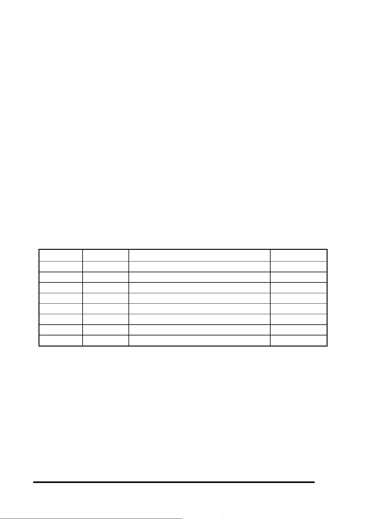
Situate monitor on workbench in preparation for removal of two (2) rear panels (Item 1)
2
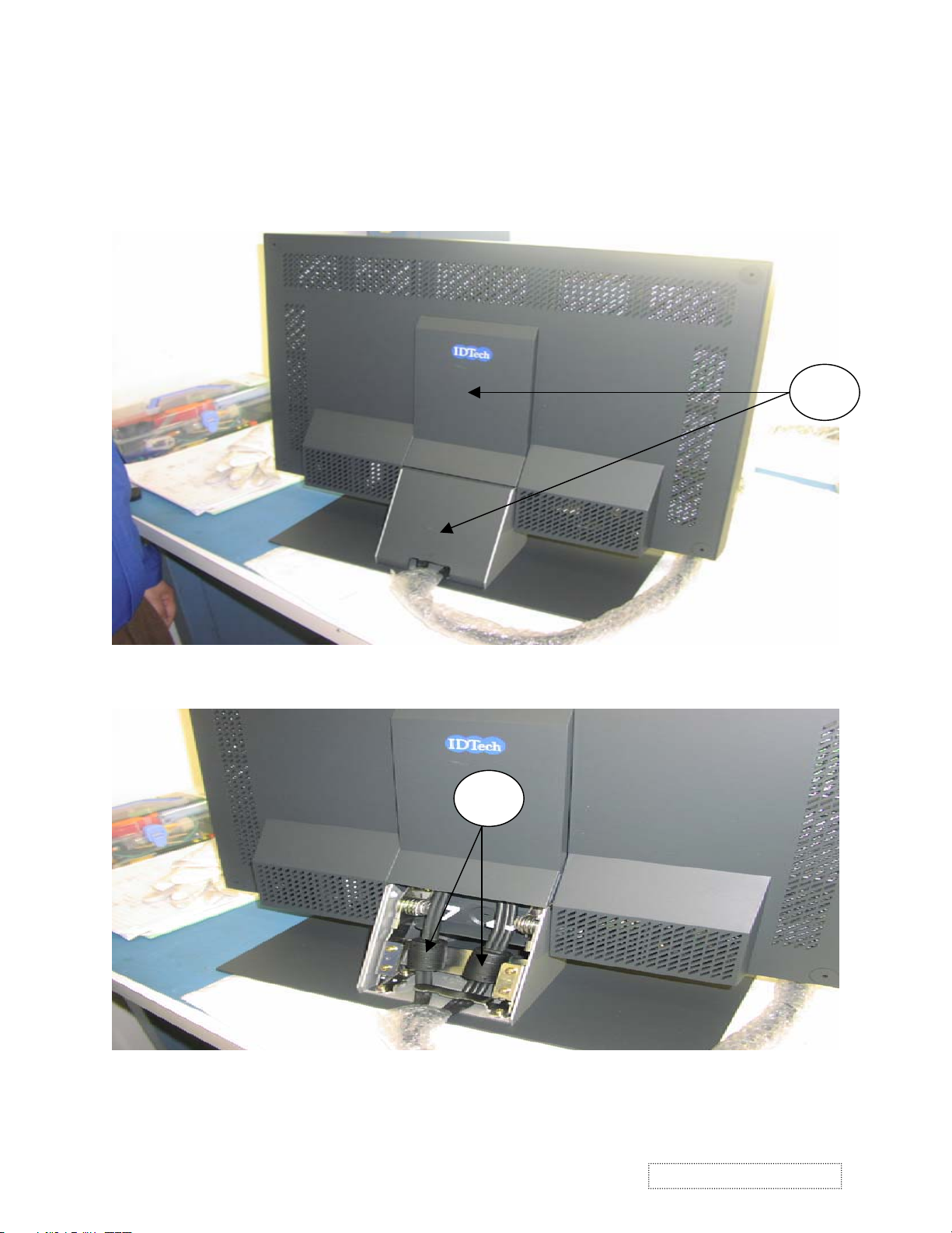
Disengage latch from bottom panel and remove panel to gain access to two (2) cables (Item 2).
ViewSonic Corporation
Page 4
Confidential – Do Not Copy
Page 6
Assembly (Dis-Assy) Procedure
For
VIEWSONIC VP2290b MONITOR
DIS-ASSEMBLY
3
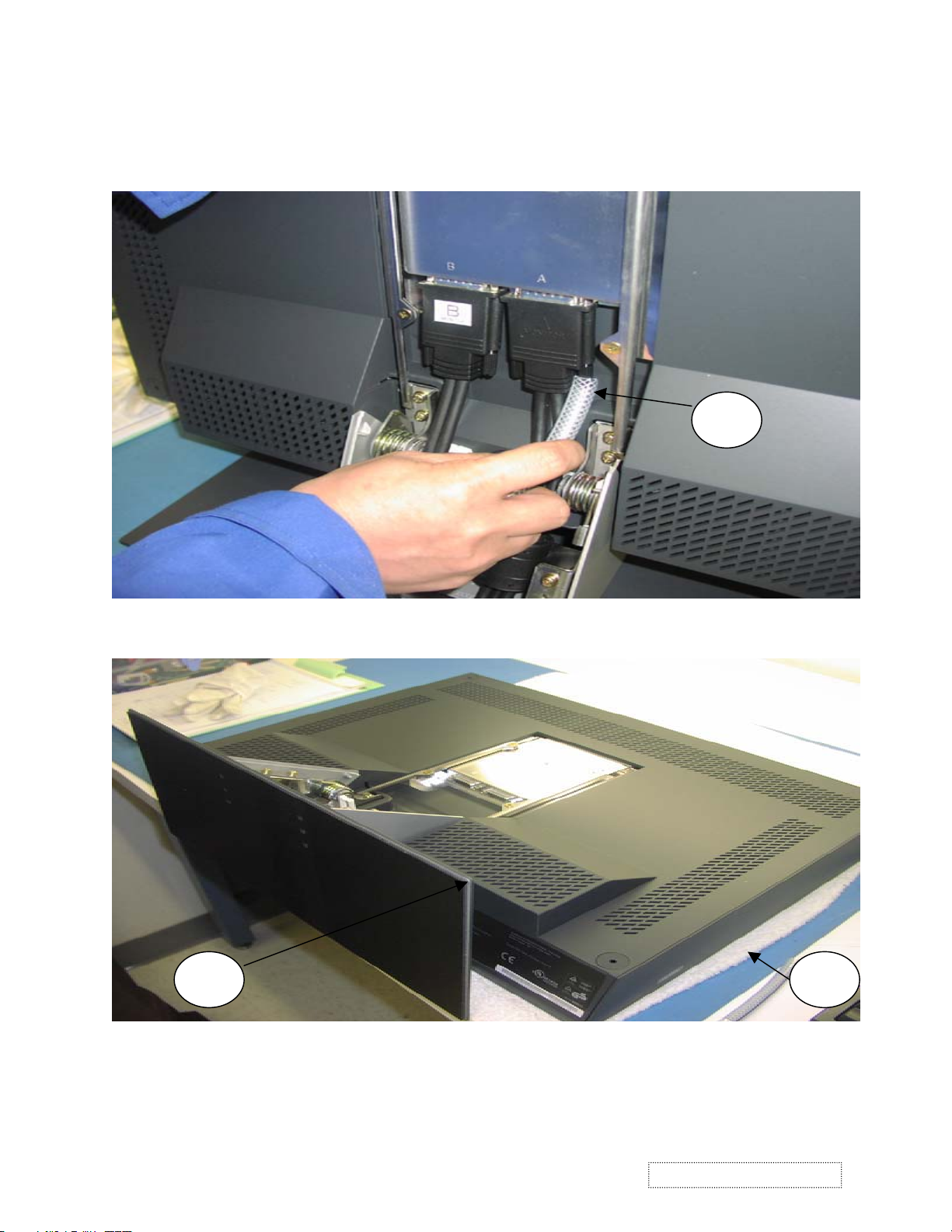
After second panel is removed, use a tube (Item 3) to loosen the four (4) connector mounting screws.
4A 4
Once both cables are removed from the monitor, lay monitor on bench with screen surface down
(protected by foam- Item 4) in preparation for removal of base (Item 4A).
ViewSonic Corporation
Page 5
Confidential – Do Not Copy
Page 7
Assembly (Dis-Assy) Procedure
For
VIEWSONIC VP2290b MONITOR
DIS-ASSEMBLY
5
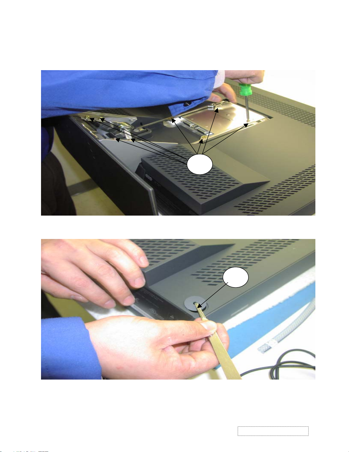
Remove eight (8) screws (Item 5) that secure monitor base. Lift and remove base from monitor.
6
Using tweezers, remove screw covers (Item 6), a total of four (4), one in each corner. Proceed to
remove four (4) screws.
ViewSonic Corporation
Page 6
Confidential – Do Not Copy
Page 8

Assembly (Dis-Assy) Procedure
For
VIEWSONIC VP2290b MONITOR
DIS-ASSEMBLY
7
Grasp and unsnap panel (Item 7) that is located on monitor bottom, beneath where base was
previously located.
8
Remove two (2) screws (Item 8) that can now be accessed.
ViewSonic Corporation
Page 7
Confidential – Do Not Copy
Page 9

Assembly (Dis-Assy) Procedure
For
VIEWSONIC VP2290b MONITOR
DIS-ASSEMBLY
9
Grasp and unsnap rear housing (Item 9) by lifting until completely separated from monitor.
10A
10
Remove ribbon cable from connector (Item 10). Peel back tape (Item 10A) to disengage cable from
metal backbone.
ViewSonic Corporation
Page 8
Confidential – Do Not Copy
Page 10

Assembly (Dis-Assy) Procedure
For
VIEWSONIC VP2290b MONITOR
DIS-ASSEMBLY
11
11A
Lift metal backbone (Item 11) and slide toward top of module to enable access to the two (2) fan
cables (Item 11A). Disconnect the two cables and note their corresponding mating connectors.
Once cables are free, remove metal backbone completely from monitor.
12
Lift and separate LCD module (Item 12) from monitor bezel (Item 12A).
ViewSonic Corporation
Page 9
Confidential – Do Not Copy
12A
Page 11

Assembly (Dis-Assy) Procedure
For
VIEWSONIC VP2290b MONITOR
DIS-ASSEMBLY
13
Lay bezel on bench to inspect for any damage; pay particular attention to function cable (Item 13).
14
Inspect four (4) guide pins in bezel (one pin in each corner- Item 14) for damage.
ViewSonic Corporation
Page 10
Confidential – Do Not Copy
Page 12

Assembly (Dis-Assy) Procedure
For
VIEWSONIC VP2290b MONITOR
DIS-ASSEMBLY
15A
15
Situate LCD module onto foam cushion (Item 15) to protect underlying PCBs. Install protective
mylar film onto front polarizer (Item 15A).
16
If LCD module (IPN F8991) is to be transported to another work area, use carrier (Item 16).
If LCD module is to be disassembled at same work bench, refer to “Assembly (Dis-Assy)
Procedure for VIEWSONIC F8991 MODULE” document.
ViewSonic Corporation
Page 11
Confidential – Do Not Copy
Page 13

Assembly (Dis-Assy) Procedure
For
VIEWSONIC VP2290b MONITOR
INSTRUCTIONS FOR ASSEMBLY
17
After removing mylar from front polarizer, situate panel assembly (IPN F8991) on edge (Item 17)
in preparation for installation into bezel.
18
18A
Situate bezel (Item 18) in front of panel. Place the bottom of bezel (with cable- Item 18A) off the
table edge to protect the underlying function control buttons.
ViewSonic Corporation
Page 12
Confidential – Do Not Copy
Page 14

Assembly (Dis-Assy) Procedure
For
VIEWSONIC VP2290b MONITOR
ASSEMBLY
19
Grasp the panel by the metal arms (Item 19) in order to lift and position into bezel.
20
Carefully lower panel into bezel (Item 20), ensuring the panel drops into the bezel guide pins.
ViewSonic Corporation
Page 13
Confidential – Do Not Copy
Page 15

Assembly (Dis-Assy) Procedure
For
VIEWSONIC VP2290b MONITOR
ASSEMBLY
21
21A
Situate metal backbone (Item 21) over panel and lower onto panel, enough to connect the two (2)
fan cables (Item 21A).
22
Connect two (2) fan cables into the original connector mates on the PCB (Item 22). Do not mix.
ViewSonic Corporation
Page 14
Confidential – Do Not Copy
Page 16

Assembly (Dis-Assy) Procedure
For
VIEWSONIC VP2290b MONITOR
ASSEMBLY
23
Ensure both fan cables are securely seated and in their original connector positions (Item 23).
24
Lower backbone fully into the bezel, ensuring backbone is properly seated (Item 24).
ViewSonic Corporation
Page 15
Confidential – Do Not Copy
Page 17

Assembly (Dis-Assy) Procedure
For
VIEWSONIC VP2290b MONITOR
ASSEMBLY
25A
25
Insert control cable into connector (Item 25) and restick tape (Item 25A).
26
Place back cover (Item 26) onto panel assembly, ensuring cover is fully seated.
ViewSonic Corporation
Page 16
Confidential – Do Not Copy
Page 18

Assembly (Dis-Assy) Procedure
For
VIEWSONIC VP2290b MONITOR
ASSEMBLY
27
Insert two (2) screws (Item 27) into bottom of monitor.
28
Grasp and install cover panel (Item 28) by snapping into position.
ViewSonic Corporation
Page 17
Confidential – Do Not Copy
Page 19

Assembly (Dis-Assy) Procedure
For
VIEWSONIC VP2290b MONITOR
ASSEMBLY
29
Insert four (4) screws into the rear cover, one in each corner. Replace screw covers (Item 29).
30A
30
Place monitor base into position (Item 30) and insert eight (8) screws (Item 30A).
ViewSonic Corporation
Page 18
Confidential – Do Not Copy
Page 20

Assembly (Dis-Assy) Procedure
For
VIEWSONIC VP2290b MONITOR
ASSEMBLY
31
Ensure monitor base (Item 31) is secure before lifting monitor into upright position.
32
With monitor in upright position, connect two (2) interface cables and secure four (4) screws
(Item 32) with the hose tool.
ViewSonic Corporation
Page 19
Confidential – Do Not Copy
Page 21

Assembly (Dis-Assy) Procedure
For
VIEWSONIC VP2290b MONITOR
ASSEMBLY
33
Install upper rear cover panel (Item 33) by snapping into position.
34A
34
Install lower rear cover panel (Item 34) by snapping into position. Ensure interface cables routed
through the opening (Item 34A). Monitor assembly is complete.
ViewSonic Corporation
Page 20
Confidential – Do Not Copy
Page 22

*Readers Response*
Dear Readers:
Thank you in advance for your feedback on our Service Manual,which allows continuous improvement
of our products. We would appreciate your completion of the Assessment Matrix below, for return to ViewSonic
Corporation.
Assessment
A. What do you think about the content after reading V P2290b Service Manual?
tinU tnellecxE dooG riaF daB
SPECIFICATION
THEORY OF OPERATION
TROUBLE SHOOTING FLOW CHART
ADJUSTMENT
EXPLODED VIEW AND MECHANICAL PARTS LIST
ELECTRICAL PARTS LIST
BLOCK DIAGRAM
SCHEMATIC DIAGRAMS
WIRING DIAGRAM
PCB LAYOUT
B.Are you satisfied with the V P2290b service manual?
metI tnellecxE dooG riaF daB
tnetnoClaunaMecivreS.1
tuoyaLlaunaMecivreS.2
gnitsildnamrofehT.3
C. Do you have any other opinion or suggestion about this service manual?
Readers basic data:
:emaN:eltiT
:ynapmoC
:ddA
:leT:xaF
:liam-E
After completing this form, please return it to ViewSonic Quality Assurance
1-909-444-8654.
(marc.maupin@viewsonic.com)
You may also e-mail any suggestions to the Director of Quality Assurance
in the USA at facsimile
 Loading...