

ViewSonic VP201b-1,VP201s-1,VLCDS26064-2W,VLCDS26064-4W Service manual

Service Manual
ViewSonic VP201b/s-1
Model No.
VLCDS26064-2W/-4W
20" Color TFT LCD Display
ViewSonic
(VP201b/s-1_SM_685 Rev. 1c Mar. 2005)
381 Brea Canyon Road, Walnut, California 91789 USA - (800) 888-8583
Copyright
Copyright
2005 by ViewSonic Corporation. All rights reserved. No part of this publication may be
¤
reproduced, transmitted, transcribed, stored in a retrieval system, or translated into any language or
computer language, in any form or by any means, electronic, mechanical, magnetic, optical, chemical,
manual or otherwise, without the prior written permission of ViewSonic Corporation.
Disclaimer
ViewSonic makes no representations or warranties, either expressed or implied, with respect to the
contents hereof and specifically disclaims any warranty of merchantability or fitness for any particular
purpose. Further, ViewSonic reserves the right to revise this publication and to make changes from time
to time in the contents hereof without obligation of ViewSonic to notify any person of such revision or
changes.
Trademarks
Optiquest is a registered trademark of ViewSonic Corporation.
ViewSonic is a registered trademark of ViewSonic Corporation.
All other trademarks used within this document are the property of their respective owners.
Revision History
1a
1b
1c
Documents Number
DCN Number ECR Number
3387, 3506,
08/28/03
25/03/04
03/09/05
3604
3773
5239
4923
Initial Release
Panel Change LG U04 Panel 16ms DCN-3773
Scalar Change to GM1601
Description of Changes EditorRevision SM Editing Date
F. Fan
A. Lu
A. Lu
ViewSonic Corporation Confidential
i
-
Do Not Copy VP201b/s-1

TABLE OF CONTENTS
1. Precautions and Safety Notices
2. Specification
3. Front Panel Function Control Description
4. Circuit Description
5. Adjustment Procedure
6. Troubleshooting Flow Chart
7. Recommended Spare Parts List
8. Exploded Diagram and Spare Parts List
9. Block Diagram
10. Schematic Diagrams
11. PCB Layout Diagrams
1
3
16
22
23
41
44
66
68
69
76
ViewSonic Corporation Confidential
ii
-
Do Not Copy VP201b/s-1

1. Precautions and Safety Notices
1. Appropriate Operation
(1) Turn off the product before cleaning.
(2) Use only a dry soft cloth when cleaning the LCD panel surface.
(3) Use a soft cloth soaked with mild detergent to clean the display housing.
(4) Use only a high quality, safety approved AC/DC power cord.
(5) Disconnect the power plug from the AC outlet if the product will not be used for a long period of time.
(6) If smoke, abnormal noise, or strange odor is present, immediately switch the LCD display off.
(7) Do not touch the LCD panel surface with sharp or hard objects.
(8) Do not place heavy objects on the LCD display, video cable, or power cord.
(9) Do not use abrasive cleaners, waxes or solvents for your cleaning.
(10) Do not operate the product under the following conditions:
- Extremely hot, cold or humid environment.
- Areas containing excessive dust and dirt.
- Near any appliance generating a strong magnetic field.
- In direct sunlight.
2. Caution
No modification of any circuit should be attempted. Service work should only be performed after you are thoroughly familiar
with all of the following safety checks and servicing guidelines.
3. Safety Check
Care should be taken while servicing this LCD display. Because of the high voltage used in the inverter circuit, the voltage is
exposed in such areas as the associated transformer circuits.
4. LCD Module Handling Precautions
4.1 Handling Precautions
(1) Since front polarizer is easily damaged, pay attention not to scratch it.
(2) Be sure to turn off power supply when connecting or disconnecting input connector.
(3) Wipe off water drops immediately. Long contact with water may cause discoloration or spots.
(4) When the panel surface is soiled, wipe it with absorbent cotton or other soft cloth.
(5) Since the panel is made of glass, it may break or crack if dropped or bumped on hard surface.
(6) Since CMOS LSI is used in this module, take care of static electricity and ensure human earth when handling.
(7) Do not open or modify the Module Assembly.
(8) Do not press the reflector sheet at the back of the module in any direction.
(9) In the event that a Module must be put back into the packing container slot after it was taken out of the
container, do not press the center of the CCFL Reflector edge. Instead, press at the far ends of the
CFL Reflector edge softly. Otherwise the TFT Module may be damaged.
(10) At the insertion or removal of the Signal Interface Connector, be sure not to rotate or tilt the Interface
Connector of the TFT Module.
ViewSonic Corporation Confidential
1
-
Do Not Copy VP201b/s-1

(11) After installation of the TFT Module into an enclosure (LCD monitor housing, for example), do not twist or
bend the TFT Module even momentarily. When designing the enclosure, it should be taken into consideration
that no bending/twisting forces may be applied to the TFT Module from outside. Otherwise the TFT Module
may be damaged.
(12) The cold cathode fluorescent lamp in the LCD contains a small amount of mercury. Please follow local
ordinances or regulations for disposal.
(13) The LCD module contains a small amount of materials having no flammability grade. The LCD module
should be supplied with power that complies with the requirements of Limited Power Source
(IEC60950 or UL1950), or an exemption should be applied for.
(14) The LCD module is designed so that the CCFL in it is supplied by a Limited Current Circuit (IEC60950
or UL1950). Do not connect the CCFL to a Hazardous Voltage Circuit.
ViewSonic Corporation Confidential
2
-
Do Not Copy VP201b/s-1
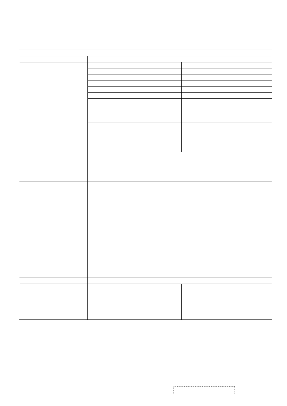
2. Specification
A. General specification:
1. General specification:
LCD panel suppliers: LG: LM201U04-A3. AUO: M201UN02 V.3
LCD panel specification:
Input signals: a. Analog R / G / B (0.7Vp-p/75 ohm) Positive.
Input connector: a. Analog D-sub 15pin x 1.
Output connector: a. USB down stream x 4.
Display data channel: DDC2B.
Signal frequency range: a. Horizontal:
a. Panel size: 20.1-inch (viewable).
b. Driver element: a - Si TFT active matrix.
c. Effective display area: 408.0 (H) X 306.0 (V) mm.
d. Pixel pitch: 0.255 (H) X 0.255 (V) mm.
e. Max. resolution: UXGA (1600X1280 pixel).
f. Display color: 16.7M colors (R, G, B 8-bit data).
g. Response time:
LG: 16 ms. (Typical)
AUO: 16 ms (Typical)
h. Color filter arrangement: R/G/B vertical stripe.
i. Black light: Edge – light type with 6CCFLs.
j. Contrast ratio:
LG: 400:1
AUO: 700:1
k. Luminance: 250cd/m2 (Typical).
l. Luminance variation: 1.54 (MAX.). (Note.1)
m. Viewing angle (CR >10): Horizontal: 170
b. Digital R /G / B DVI rev. 1.0 (TMDS single link)
c. H & V separate Sync: TTL level; Polarity: Positive or Negative.
d. H & V composite Sync: TTL level; Polarity: Positive or Negative.
e. SOG (Sync level 0.3Vp-p).
b. Digital DVI-I 29 pin x 1. (Analog + Digital)
c. USB up stream x1.
a-1. Analog: 30KHz ~ 92KHz.
a-2. Digital: 30KHz ~ 92KHz.
b. Vertical: 50Hz ~ 85*
Note: *
1
The maximum vertical refresh rate of 1600x1200 as below:
1
Hz.
o
, Vertical: 170o.
Analog input: 60 Hz.
Digital input: 60 Hz.
c. Pixel clock:
c-1. Analog: 165MHz.
c-2. Digital: 165MHz.
d. Non-interlaced.
Resolution: 1600x1200. (UXGA)
Power supply: AC Input Range: AC 90 to 264V, 50/60Hz ± 3Hz, 1.5A.
Less then 50Ap. For 115VAC. Inrush current
Power Consumption:
Less then 100Ap. For 230V
Less then 73W. On mode.
AC
.
Less then 4W. Active off mode.
Less then 2W. DC power off.
ViewSonic Corporation Confidential
3
-
Do Not Copy VP201b/s-1
b
B. Physical specification.
Overall dimension:
Mechanical adjustment:
Packaging: a. Carton dimension:
Accessories: Power cable 1.8m.
3. Regulatory & Standard certification.
Regulatory standards UL, cUL, FCC-B, CB, CE, ENERGY, NOM, TUV/GS, TUV ERGO (covers
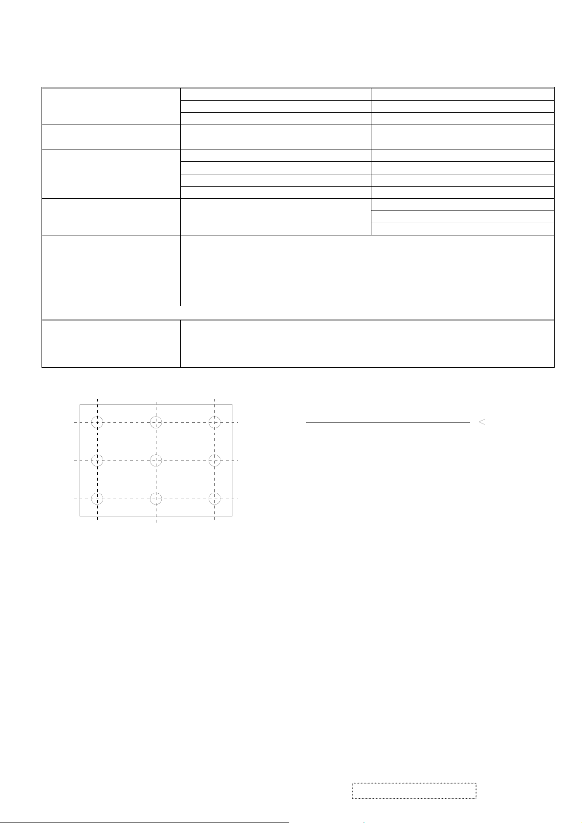
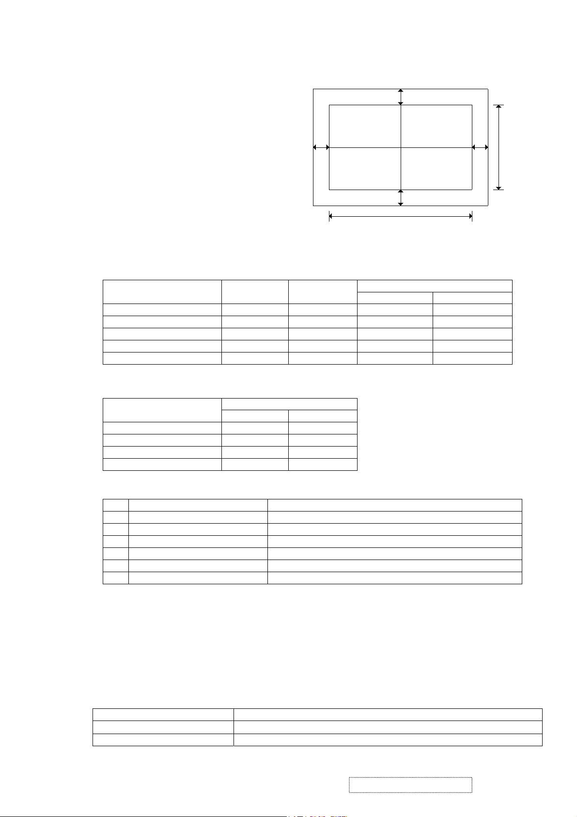
Note.1: Luminance variation:
50%90%
L = 408mm / W = 306mm
FIG.1 Luminance test point.
a. Height: 480.55mm.
b. Width: 448.00mm.
c. Depth: 266.65mm.
a. Net weight: 8.5kg. Weight:
b. Gross weight: 11.2kg.
a. Tilt: +25o ~ -5o.
b. Swivel:
c. Height adjust: 110mm.
d. Pivot: 90
± 45
o
o
.
.
a. Height: 494mm.
b. Width: 345mm.
c. Depth: 560mm.
User guide (English).
CD ROM.
Warranty card.
HD15 - HD15 cable.
DVI (D) – DVI (D) cable.
ISO13406-2 & MPRII), TCO’03(for VP201s/VP2000s), TCO99 (for VP201
NEMKO, SEMKO, DEMKO, FIMKO, GOST-R + 20 ORIGINAL COPIES
HYGIENIC, (SASO), PCBC, VCCI, BSMI, CCC, (PSB), (C-TICK), TUV-S
10%
MAX. Luminance in 9 point (1 ~ 9)
10%
BU =
1.54
MIN. Luminance in 9 point (1 ~ 9)
50%
90%
),
ViewSonic Corporation Confidential
4
-
Do Not Copy VP201b/s-1

C. Chassis alignment / Test specification.
1. Interface board function test.
1.1 Function key: Power, 1, ▲, ▼, 2 key.
1.2 Basic function check.
1.2.1 Input 1600x1200 / 60Hz, cross-hatch reverse pattern.
1.2.2 Push “1” & “2” key, selection Auto image adjust, Contrast, Brightness, Input select,
Color, Manual image adjust, Setup menu, Memory recall function.
1.2.3 Push “▲” or “▼” key check Contrast, Brightness, Input select, Color, H/V position, H
size, Fine tune, Sharpness, Scaling Language select, OSD position OSD timeout, OSD
background function.
1.2.4 Push “2” key, to select Analog / DVI-A / DVI-D signal.
1.2.5 While main menu is not display at normal status, their buttons function as “▲” & “▼” of
Contrast or Brightness with OSD.
2. Interface power test.
2.1 The test point:
2.1.1 TP251 = NA.
2.1.2 TP252 = 5V ± 5%.
2.1.3 TP253 = 18V ± 5%.
3. OSD function.
Auto Image Adjust*2
Contrast/Brightness:
Contrast, Brightness.
Input Select:
D-Sub, DVI-A, DVI-D.
Color Adjust:
SRBG, 9300K, 6500K (default), 5400K, 5000K, User Color (R, G, B).
Information:
Resolution, Horizontal Frequency, Vertical Frequency, Model Number, Serial Number, Web Site.
Manual Image Adjust:
H. / V. Position*2 (H. Position, V. Position), H. Size*2, Fine Tune*
Scaling
3
*
(Fill Screen, Fill Aspect Ratio*
Setup Menu:
Language:
English, French, German, Spanish, Italian, Finnish, Japanese, Traditional Chinese, Simplified
Chinese.
Resolution Notice:
Enable, Disable.
Input Priority:
D-Sub, DVI-A, DVI-D, Auto Search.
OSD Position:
H. Position, V. Position.
OSD Timeout:
5SEC, 15SEC, 30SEC, 60SEC
OSD Background:
On, Off.
Memory Recall
Note:
2
These functions are not available in Digital mode; the word is black and can’t select.
*
When auto tuning, the image should not be blanking.
3
These function are not available in 1600x1200 mode, the word is black and can’t select.
*
4
When the input signal is 4:3, the “Fill Aspect ratio” size same as “Fill Screen”.
*
4
, 1:1).
2
,
ViewSonic Corporation Confidential
5
-
Do Not Copy VP201b/s-1
D. Instrument alignment.
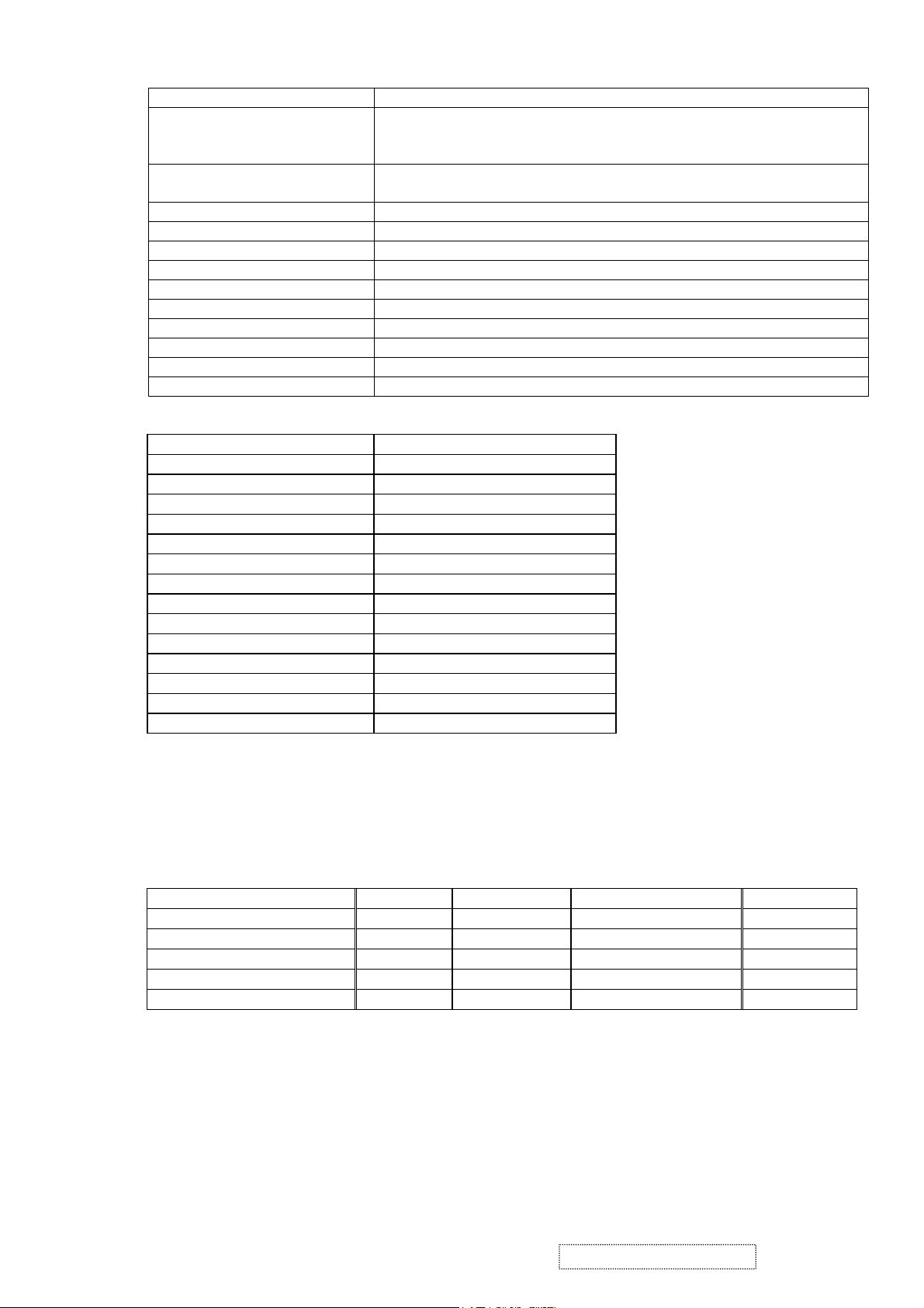
1 Initial Settings
1.1 Set contrast to 70% and brightness to 100%.
1.2 Input a 640x480 / 60Hz, 5-block (5-MOSAIC) pattern (input level 100IRE 0.7Vp-p), then
activate the White Balance function.
Set SRBG/9300K / 6500K / 5400K / 5000K, R G B Gain as shown below:
sRGB 9300K 6500K 5400K 5000K
Analog DVI Analog DVI Analog DVI Analog DVI Analog DVI
R Gain 255 255 255 255 255 255 255 255 255 255
G Gain 255 255 255 255 255 255 255 255 255 255
B Gain 255 255 255 255 255 255 255 255 255 255
2. 9300K alignment:
2.1 Input 1600x1200 / 60Hz & full white pattern at 100IRE.
2.2 Adjust R, G, and B Gain to meet following chromaticity spec:
9300K → x = 0.283 ± 0.005, y = 0.298 ± 0.005, Y > 150cd/m
3. 6500K alignment:
3.1 Input 1600x1200 / 60Hz & full white pattern at 100IRE.
3.2 Adjust R, G and B Gain to meet following chromaticity spec:
6500°K → x = 0.313 ±0.005, y = 0.329 ± 0.005, Y > 200cd/m
4. 5400K alignment:
4.1 Input 1600x1200 / 60Hz & full white pattern at 100IRE.
4.2 Adjust R, G, and B Gain to meet following chromaticity spec:
5400K → x = 0.335 ± 0.005, y = 0.350 ± 0.005, Y > 180cd/m
5. 5000K alignment:
5.1 Input 1600x1200 / 60Hz & full white pattern at 100IRE.
5.2 Adjust R, G and B Gain to meet following chromaticity spec:
5000°K → x = 0.346 ±0.005, y = 0.359 ± 0.005, Y > 180cd/m
6. sRGB alignment:
6.1 Input 1600x1200 / 60Hz & full white pattern at 100IRE.
6.2 Adjust R, G and B Gain to meet following chromaticity spec:
sRGB → x = 0.313 ±0.005, y = 0.329 ± 0.005, Y > 200cd/m
7. 64 grays and 16 grays pattern check:
7.1 Input a 1600x1200 / 60Hz, 64 gray-level pattern at 100IRE, with brightness set to 100% and
contrast set to 70%
7.2 Verify that under the 9300K / 6500K / 5400K / 5000K settings, no more than 2 of the 64
grays are saturated.
7.3 Input a 1600x1200 / 60Hz, 16 gray-level pattern at 100IRE, with brightness set to 100% and
contrast set to 100%.
7.4 Verify that under the 9300K / 6500K / 5400K / 5000K settings, no more than 4 of the 16 grays are
saturated.
2
(Both analog & DVI).
2
(Both analog & DVI).
2
(Both analog & DVI).
2
(Both analog & DVI).
2
(Both analog & DVI).
ViewSonic Corporation Confidential
6
-
Do Not Copy VP201b/s-1
E. Image test
1. Picture size & position.
1.1 Picture size.
Input analog timing modes 1 ~ 26 and DVI timing modes 1 ~ 25:
H-size: 408mm
V-size: 306mm
± 1mm.
± 1mm.
(Extra 640x350)
1.2 Screen center.
a. 1600x1200: H ± 1mm, V ± 1mm.
b. Others modes: H ± 1.5mm, V ± 1mm.
1.3 Picture position (refer to FIG.2).
H-position:
V-position:
︱g3-g4︱ ≦ 1.5mm.
︱g1-g2︱ ≦ 1.5mm.
2. Luminance test.
2.1 Input a 1600x1200 / 60Hz full white pattern at 100IRE with brightness set to 100% and
contrast set to 70%.
Color temperature x y
sRGB 0.313 ± 0.01 0.329 ± 0.01 >200 nit >200 nit
9300K 0.283 ± 0.01 0.298 ± 0.01 >150 nit >150 nit
6500K 0.313 ± 0.01 0.329 ± 0.01 >200 nit >200 nit
5400K 0.335 ± 0.01 0.350 ± 0.01 >180 nit >180 nit
5000K 0.346 ± 0.01 0.359 ± 0.01 >180 nit >180 nit
g3
g1
306mm
g4
g2
408mm
FIG. 2
Y (Luminance)
Analog DVI
2.2 Input a1600x1200 / 60Hz full white pattern at 100IRE with brightness set to 100% and
contrast set to 100%.
Color temperature
Y (Luminance)
Analog DVI
9300K >220 nit >220 nit
6500K >220 nit >220 nit
5400K >220 nit >220 nit
5000K >220 nit >220 nit
3. Picture performance test.
3.1 Picture quality:
Test pattern signal
The following image faults shall not be conspicuous:
1 100IRE white raster pattern Seam, Noise, Beat, Flicker
2 Cross hatch pattern Ringing, Overshoot, Smear, V-jitter, H-jitter
3 Color bar Color distortion, Noise, Beat, Color tangent
4 Gray scale (16 steps) Noise, Beat, Gamma distortion
5 1 dot ON / 1 dot OFF pattern Noise, Flicker
6 40IRE gray raster Noise, Beat, Gamma distortion
3.2 DVI performance test.
3.2.1 3.2.2 Test conditions:
a. VG828 digital pattern generator.
b. “TTL” DVI-D single link cable.
3.2.2 Test condition:
a. a. Resolution: 1600x1200; refresh rate: 75KHz vertical / 60Hz horizontal.
b. b. 16, 32, 64, and 256-level horizontal gray scales.
c. c. 16, 32, 64, and 256-level vertical gray scales.
4. Shortcut keys and factory presets
4.1 Shortcut keys: Press the following keys to adjust settings directly, when the OSD is not active.
[
1]. Main Menu.
[2].
Select next input. (Sequence: D-SUB
→ DVI-A → DVI-D)
[UP] or [DOWN] arrow. Directly activate the Contrast menu. Switch to Brightness menu
ViewSonic Corporation Confidential
7
-
Do Not Copy VP201b/s-1
by pushing button [2].
[UP] + [DOWN] arrows. Recall either Contrast or Brightness settings while the Contrast or
Brightness adjustment OSD is active, or recall both Contrast and
the OSD is not active.
[1] + [2].
Toggle 720x400 and 640x400 mode when input 720x400 or 640x400
mode.
[1] + [UP] + [DOWN]. White Balance (press and hold for 5 seconds).
[2] + [UP] + [DOWN]. Video Mirror Function
[1] + [DOWN]. Power Lock / Power Unlock (press and hold for 10 seconds).
[1] + [UP]. OSD Lock / OSD Unlock (press and hold for 10 seconds).
DC-Power + [2] + [UP]. Copy EDID to E
2
PROM.
DC-Power + [1]. Factory mode. (Burn in mode on)
DC-Power + [2] + [DOWN]. Burn in mode on.
DC-Power + [UP] + [DOWN]. Burn in mode off.
DC-Power + [2]. All mode recall.
AC-Power on. Enter ISP mode.
4.2 All mode recall settings:
Contrast 70%.
Brightness 100%.
Color Temperature 6500K.
Scaling Full Screen.
Input Priority Auto Search.
OSD H. Position 50%.
OSD V. Position 50%.
OSD Time Out 15 Sec
OSD Background On
Resolution Notice Enabled
720x400/640x400 720x400
User color. 50%.
Language. English.
Clear burn in mode.
Clear user mode table.
4.3 Factory shipment settings:
4.3.1 Main power switch: Off.
4.3.2 AC power button: Off.
4.3.3 Others settings same as "All mode recall" settings.
5. Power management tests.
5.1 Power consumption test table:
Monitor status LED color Video signal Power consumption Recover time
Normal / Unstable / Warning Green Active <73W
Power save Amber Blank <4W 5sec
Aging
Note
NA <73W
DC power off Off NA <2W
AC power off Off NA -
See note:
Amber (0.5sec) → Green (0.5sec) → Amber (0.5sec) → Green (0.5sec)… continuously.
6. DDC test.
6.1 DDC / EDID specification compliance requirement.
The data that is transmitted shall be stored in the monitor in non-volatile memory, which is a
requirement of the VESA EDID version 3.0 standard.
6.2 IC954 EEPROM data see Appendix-B item a.
6.3 The EDID data see Appendix-B,
VP201s analog & DVI-A are same as item b, the DVI-D input1 see item c;
VP201b analog & DVI-A are same as item d, the DVI-D input1 see item e;
ViewSonic Corporation Confidential
8
-
Do Not Copy VP201b/s-1
VP201b-H analog & DVI-A are same as item f, the DVI-D input1 see item g;
VP2000s analog & DVI-A are same as item h, the DVI-D input1 see item i;
7. USB test (VP201s/b only)
7.1 Use a USB test hub such as "UPT2 USB2.0 8-port tester" to test USB up stream and down stream
transfers. Each port must pass the test.
7.2 Use a PC to check the USB VID, which should be 0543, and the PID, which should be 1169.
7.3 For USB test settings see Appendix E.
8. For auto alignment, it is necessary to execute the auto image adjust command for 3 DOS modes
(640x350, 720x400, 640x400).
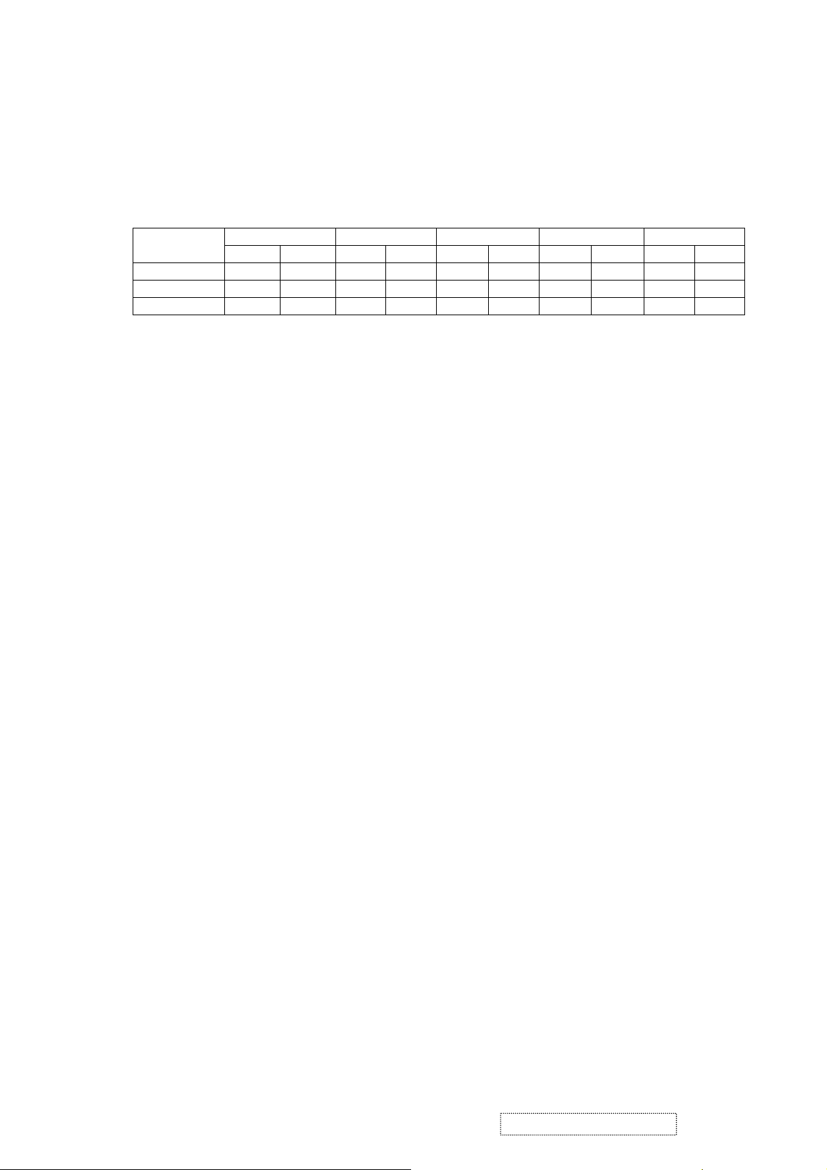
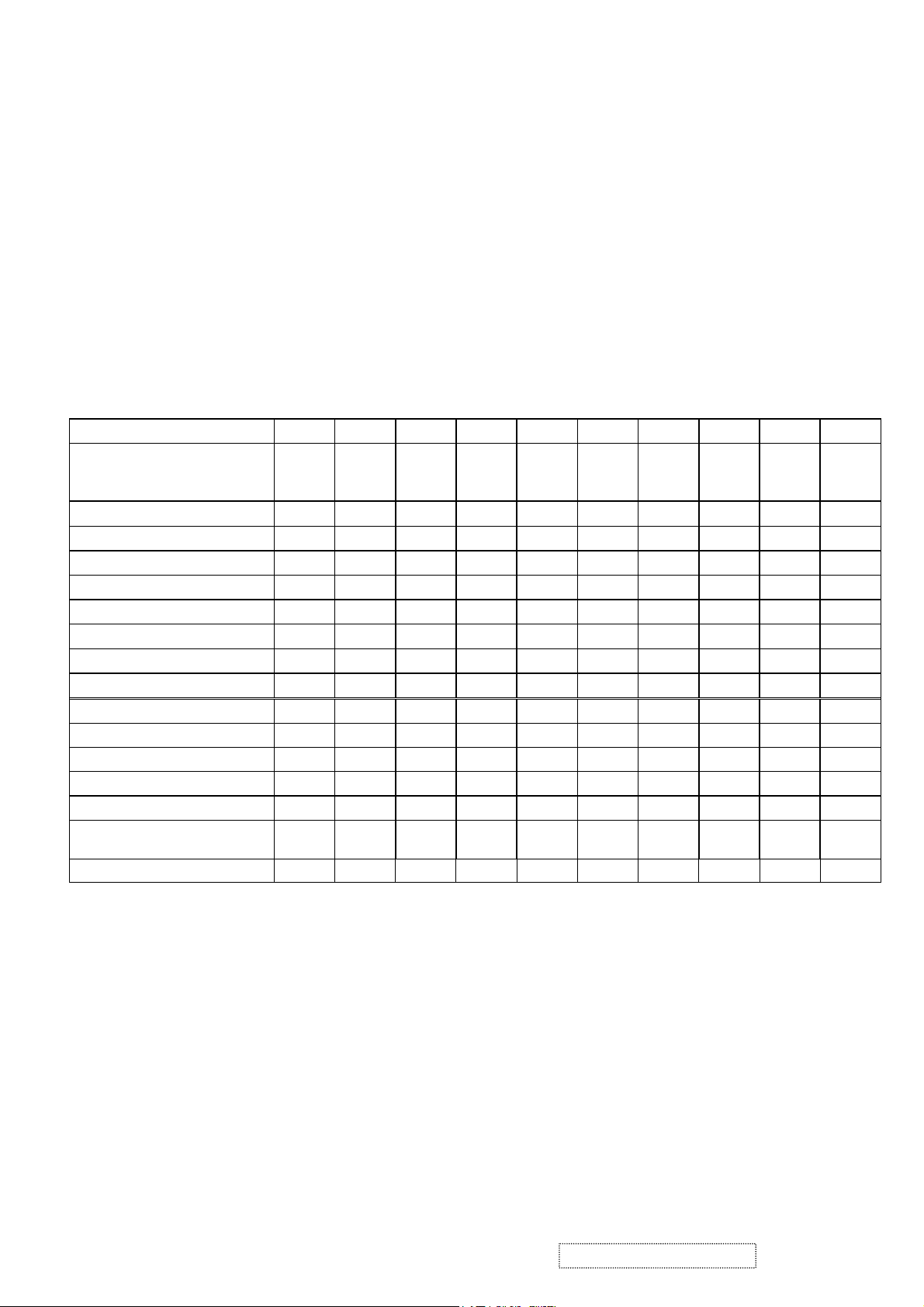
F. Analog and Digital timing chart.
Mode No. 1 2 3 4 5 6 7 8 9 10
TEXT
Mode Name
640 x
350
Horizontal Freq. 31.468 31.468 24.688 31.469 35.000 37.861 37.500 43.269 31.469
VGA
640 x
400
VESA
640 x
480
VESA
640 x
480
MAC
640 x
480
VESA
640 x
480
VESA
640 x
480
VESA
640 x
480
TEXT
720 x
400
VESA
800 x
600
35.156
Video clock Freq. 25.175 25.175 19.75 25.175 30.240 31.500 31.500 36.000 28.322 36.000
Sync. Polarity
+ - - - - - - - - +
H. total (Dots) 800 800 800 800 864 832 840 832 900 1024
H. sync. (Dots) 96 96 64 96 64 40 64 56 108 72
H. back porch (Dots) 48 48 80 48 96 128 120 80 54 128
H. active (Dots) 640 640 640 640 640 640 640 640 720 800
H. front porch (Dots) 16 16 16 16 64 24 16 56 18 24
Vertical Freq. (Hz) 70.087 70.087 49.673 59.940 66.667 72.809 75.000 85.008 70.087 56.250
Sync. Polarity
- + + - - - - - + +
V. total (Lines) 449 449 497 525 525 520 500 509 449 625
V. sync. (Lines) 2 2 4 2 3 3 3 3 2 2
V. back porch (Lines) 60 35 10 33 39 28 16 25 35 22
V. active
(Lines)
350 400 480 480 480 480 480 480 400 600
V. front porch (Lines) 37 12 3 10 3 9 1 1 12 1
ViewSonic Corporation Confidential
9
-
Do Not Copy VP201b/s-1
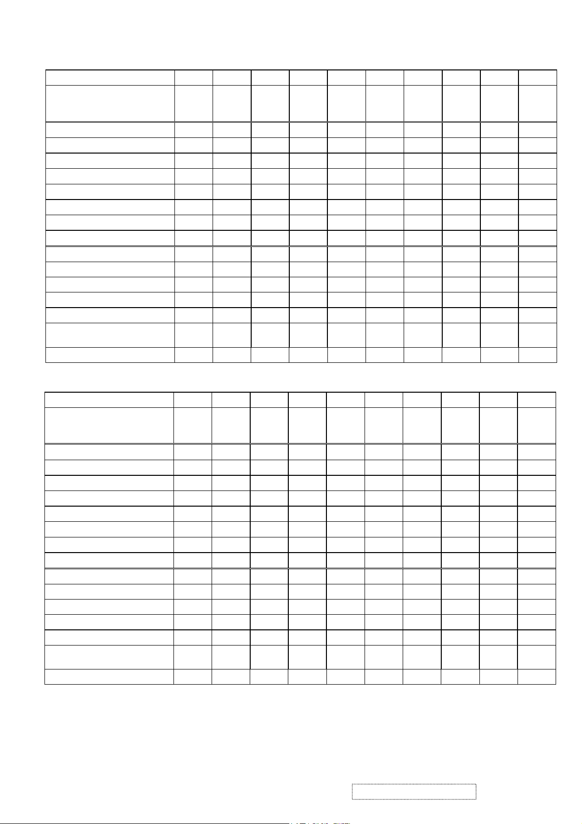
Mode No.
Mode Name
Horizontal Freq. (KHz) 37.879 48.077 46.875 53.674
Video clock Freq. 40.000 50.000 49.500 56.250 57.285 65.000 75.000 78.084 78.750 94.500
Sync. Polarity
H. total (Dots) 1056 1040 1056 1048 1152 1344 1328 1344 1312 1376
H. sync. (Dots) 128 120 80 64 64 136 136 136 96 96
H. back porch (Dots) 88 64 160 152 224 160 144 160 176 208
H. active (Dots) 800 800 800 800 832 1024 1024 1024 1024 1024
H. front porch (Dots) 40 56 16 32 32 24 24 24 16 48
Vertical Freq. (Hz) 60.317 72.188 75.000 85.061 74.553 60.004 70.069 72.082 75.029 84.997
Sync. Polarity
V. total (Lines) 628 666 625 631 667 807 806 806 800 808
V. sync. (Lines) 4 6 3 3 3 6 6 6 3 3
V. back porch (Lines) 23 23 21 27 37 29 29 29 28 38
V. active
(Lines)
V. front porch (Lines) 1 37 1 1 3 3 3 3 1 1
11 12 13 14 15 16 17 18 19 20
VESA
800 x
600
+ + + + - - - - + +
+ + + + - - - - + +
600 600 600 600 624 768 768 768 768 768
VESA
800 x
600
VESA
800 x
600
VESA
800 x
600
MAC
832 x
624
49.727
VESA
1024 x
768
48.363
VESA
1024 x
768
56.476 58.099
XGA
1024 x
768
VESA
1024 x
768
60.023 68.677
VESA
1024 x
768
Mode No.
Mode Name
Horizontal Freq. (KHz) 68.681 60.000 75.231 63.981 79.976 91.146
Video clock Freq. 100.00 108.00 130.00 108.00 135.00 157.50 74.250 162.00
Sync. Polarity
H. total (Dots) 1456 1800 1728 1688 1688 1728 1650 2160
H. sync. (Dots) 128 112 136 112 144 160 40 192
H. back porch (Dots) 144 312 224 248 248 224 270 304
H. active (Dots) 1152 1280 1280 1280 1280 1280 1280 1600
H. front porch (Dots) 32 96 88 48 16 64 60 64
Vertical Freq. (Hz) 75.062 60.000 74.857 60.020 75.025 85.024 60.000 60.000
Sync. Polarity
V. total (Lines) 915 1000 1005 1066 1066 1072 750 1250
V. sync. (Lines) 3 3 4 3 3 3 5 3
V. back porch (Lines) 39 36 38 38 38 44 20 46
V. active
(Lines)
V. front porch (Lines) 3 1 3 1 1 1 5 1
21 22 23 24 25 26 27 28 29 30
APPLE
1152x
870
- + - + + + - +
- + + + + + - +
870 960 960 1024 1024 1024 720 1200
VESA
1280 x
960
VESA
1280 x
960
VESA
1280 x
1024
VESA
1280 x
1024
VESA
1280 x
1024
HDTV
1280 x
720
45.000
VESA
1600 x
1200
75.000
ViewSonic Corporation Confidential
10
-
Do Not Copy VP201b/s-1

G. Appendix B: DDC contents.
a. IC954 128 bytes EEPROM of VSC USB Vendor ID.
0 1 2 3 4 5 6 7 8 9
0 05 43 11 69 0E 00 18 00 0A 00
10 31 80 FF FF FF FF FF FF FF FF
20 FF FF FF FF FF FF FF FF FF FF
30 FF FF FF FF FF FF FF FF FF FF
40 FF FF FF FF FF FF FF FF FF FF
50 FF FF FF FF FF FF FF FF FF FF
60 FF FF FF FF FF FF FF FF FF FF
70 FF FF FF FF FF FF FF FF FF FF
80 FF FF FF FF FF FF FF FF FF FF
90 FF FF FF FF FF FF FF FF FF FF
100 FF FF FF FF FF FF FF FF FF FF
110 FF FF FF FF FF FF FF FF FF FF
120 FF FF FF FF FF FF FF FF
b. 128 bytes of EDID code for VP201s analog.
0 1 2 3 4 5 6 7 8 9
0
10
20
30
40
50
60
70
80
90
100
110
120
00 FF FF FF FF FF FF 00 5A 63
18 0C 01 01 01 01 01 0E 01 03
0E 29 1F 78 2E 60 E5 A3 57 4B
9C 25 11 50 54 BF EF 80 A9 40
81 80 81 40 71 4F 61 59 45 59
31 59 01 01 48 3F 40 30 62 B0
32 40 40 C0 13 00 98 32 11 00
00 1E 00 00 00 FF 00 41 32 55
30 34 30 31 30 30 30 30 31 0A
00 00 00 FD 00 32 55 1E 5C 11
00 0A 20 20 20 20 20 20 00 00
00 FC 00 56 50 32 30 31 73 0A
20 20 20 20 20 20 00 3C
ViewSonic Corporation Confidential
11
-
Do Not Copy VP201b/s-1
c. 128 bytes of EDID code for VP201s digital.
0 1 2 3 4 5 6 7 8 9
0 00 FF FF FF FF FF FF 00 5A 63
10 18 0C 01 01 01 01 01 0E 01 03
20 80 29 1F 78 2E 60 E5 A3 57 4B
30 9C 25 11 50 54 BF EF 80 A9 40
40 81 80 81 40 71 4F 61 59 45 59
50 31 59 31 0A 48 3F 40 30 62 B0
60 32 40 40 C0 13 00 98 32 11 00
70 00 1E 00 00 00 FF 00 41 32 55
80 30 34 30 31 30 30 30 30 31 0A
90 00 00 00 FD 00 32 55 1E 5C 11
100 00 0A 20 20 20 20 20 20 00 00
110 00 FC 00 56 50 32 30 31 73 0A
120 20 20 20 20 20 20 00 91
d. 128 bytes of EDID code for VP201b analog.
0 1 2 3 4 5 6 7 8 9
0 00 FF FF FF FF FF FF 00 5A 63
10 11 69 01 01 01 01 01 0E 01 03
20 0E 29 1F 78 2E 60 E5 A3 57 4B
30 9C 25 11 50 54 BF EF 80 A9 40
40 81 80 81 40 71 4F 61 59 45 59
50 31 59 01 01 48 3F 40 30 62 B0
60 32 40 40 C0 13 00 98 32 11 00
70 00 1E 00 00 00 FF 00 41 32 31
80 30 34 30 31 30 30 30 30 31 0A
90 00 00 00 FD 00 32 55 1E 5C 11
100 00 0A 20 20 20 20 20 20 00 00
110 00 FC 00 56 50 32 30 31 62 0A
120 20 20 20 20 20 20 00 1B
ViewSonic Corporation Confidential
12
-
Do Not Copy VP201b/s-1

e. 128 bytes of EDID code for VP201b digital.
0 1 2 3 4 5 6 7 8 9
0 00 FF FF FF FF FF FF 00 5A 63
10 11 69 01 01 01 01 01 0E 01 03
20 80 29 1F 78 2E 60 E5 A3 57 4B
30 9C 25 11 50 54 BF EF 80 A9 40
40 81 80 81 40 71 4F 61 59 45 59
50 31 59 31 0A 48 3F 40 30 62 B0
60 32 40 40 C0 13 00 98 32 11 00
70 00 1E 00 00 00 FF 00 41 32 31
80 30 34 30 31 30 30 30 30 31 0A
90 00 00 00 FD 00 32 55 1E 5C 11
100 00 0A 20 20 20 20 20 20 00 00
110 00 FC 00 56 50 32 30 31 62 0A
120 20 20 20 20 20 20 00 70
f. 128 bytes of EDID code for VP201b-H analog.
0 1 2 3 4 5 6 7 8 9
0 00 FF FF FF FF FF FF 00 5A 63
10 11 69 01 01 01 01 01 0E 01 03
20 0E 29 1F 78 2E 60 E5 A3 57 4B
30 9C 25 11 50 54 BF EF 80 A9 40
40 81 80 81 40 71 4F 61 59 45 59
50 31 59 01 01 48 3F 40 30 62 B0
60 32 40 40 C0 13 00 98 32 11 00
70 00 1E 00 00 00 FF 00 41 32 44
80 30 34 30 31 30 30 30 30 31 0A
90 00 00 00 FD 00 32 55 1E 5C 11
100 00 0A 20 20 20 20 20 20 00 00
110 00 FC 00 56 50 32 30 31 62 0A
120 20 20 20 20 20 20 00 08
ViewSonic Corporation Confidential
13
-
Do Not Copy VP201b/s-1

g. 128 bytes of EDID code for VP201b-H digital.
0 1 2 3 4 5 6 7 8 9
0 00 FF FF FF FF FF FF 00 5A 63
10 11 69 01 01 01 01 01 0E 01 03
20 80 29 1F 78 2E 60 E5 A3 57 4B
30 9C 25 11 50 54 BF EF 80 A9 40
40 81 80 81 40 71 4F 61 59 45 59
50 31 59 31 0A 48 3F 40 30 62 B0
60 32 40 40 C0 13 00 98 32 11 00
70 00 1E 00 00 00 FF 00 41 32 44
80 30 34 30 31 30 30 30 30 31 0A
90 00 00 00 FD 00 32 55 1E 5C 11
100 00 0A 20 20 20 20 20 20 00 00
110 00 FC 00 56 50 32 30 31 62 0A
120 20 20 20 20 20 20 00 5D
h. 128 bytes of EDID code for VP2000s analog.
0 1 2 3 4 5 6 7 8 9
0 00 FF FF FF FF FF FF 00 5A 63
10 1A 23 01 01 01 01 01 0E 01 03
20 0E 29 1F 78 2E 60 E5 A3 57 4B
30 9C 25 11 50 54 BF EF 80 A9 40
40 01 01 81 80 81 40 71 4F 61 59
50 45 59 31 59 48 3F 40 30 62 B0
60 32 40 40 C0 13 00 98 32 11 00
70 00 1E 00 00 00 FF 00 50 39 34
80 30 34 30 31 30 30 30 30 31 0A
90 00 00 00 FD 00 32 55 1E 5C 11
100 00 0A 20 20 20 20 20 20 00 00
110 00 FC 00 56 50 32 30 30 30 73
120 0A 20 20 20 20 20 00 1F
ViewSonic Corporation Confidential
14
-
Do Not Copy VP201b/s-1

i. 128 bytes of EDID code for VP2000s digital.
0 1 2 3 4 5 6 7 8 9
0 00 FF FF FF FF FF FF 00 5A 63
10 1A 23 01 01 01 01 01 0E 01 03
20 80 29 1F 78 2E 60 E5 A3 57 4B
30 9C 25 11 50 54 BF EF 80 A9 40
40 81 80 81 40 71 4F 61 59 45 59
50 31 59 31 0A 48 3F 40 30 62 B0
60 32 40 40 C0 13 00 98 32 11 00
70 00 1E 00 00 00 FF 00 50 39 34
80 30 34 30 31 30 30 30 30 31 0A
90 00 00 00 FD 00 32 55 1E 5C 11
100 00 0A 20 20 20 20 20 20 00 00
110 00 FC 00 56 50 32 30 30 30 73
120 0A 20 20 20 20 20 00 74
ViewSonic Corporation Confidential
15
-
Do Not Copy VP201b/s-1
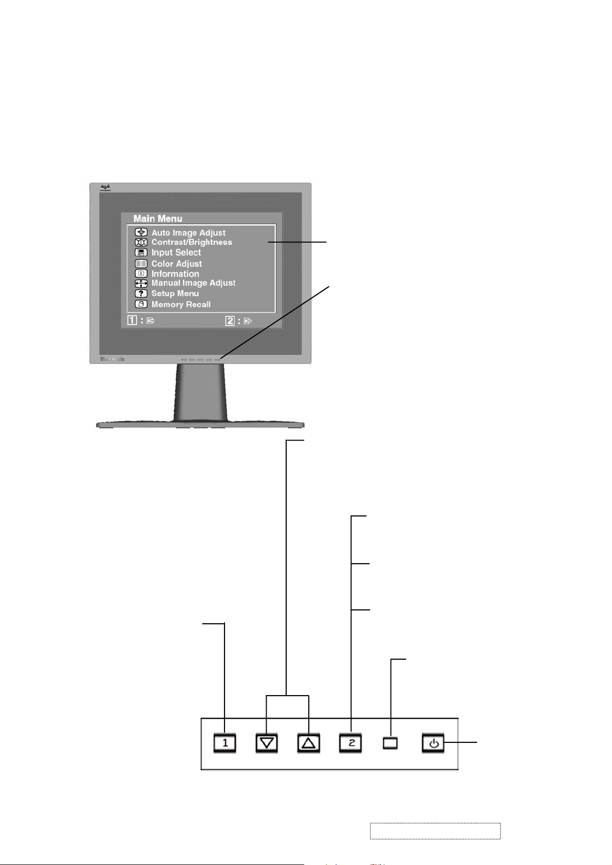
3. Front Panel Function Control Description
Adjusting the Screen Image
Use the buttons on the front control panel to display and adjust the OnView®
controls which display on the screen. The OnView controls are explained at the
of the next page.
top
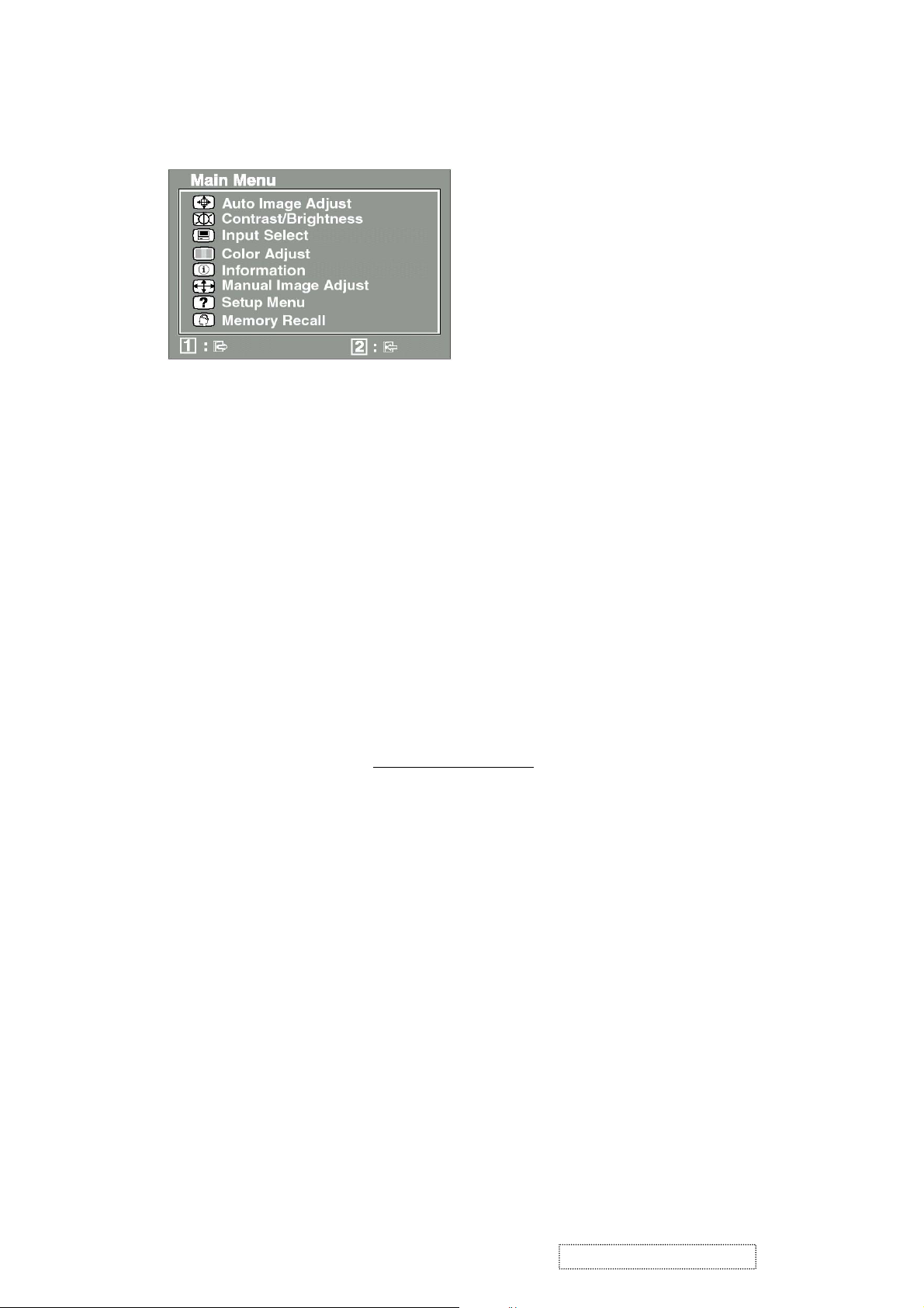
Main Menu
with OnView controls
Front Control Panel
shown below in detail
Displays the Main Menu
or exits the control screen
and saves adjustments.
Scrolls through menu options and
adjusts the displayed control.
Also a shortcut to display the
Contrast adjustment control
screen.
Displays the control
screen for the highlighted
control.
Also toggles between two
controls on some
screens.
Also a shortcut to toggle
analog and digital connection.
Power light
Green = ON
Orange = Power
Saving
ViewSonic Corporation Confidential
16
Power
On/Off
-
Do Not Copy VP201b/s-1
Do the following to adjust the screen image:
To display the Main Menu, press button [1].
1
NOTE:
All OnView menus and adjustment screens disappear automatically
after about 30 seconds.
To select a control you want to adjust, press ▲ or ▼ to scroll up or down the
2
Main Menu.
After the control is selected, press button [2].
3
To adjust the control, press the up ▲ or down ▼ buttons.
4
To save the adjustments and exit the menu, press button [1]
5
twice
.
The following tips may help you optimize your display:
• Adjust your computer's graphic card so that it outputs a video signal 1600 x
1200 @ 60 Hz to the LCD display. (Look for instructions on “changing the
refresh rate” in your graphic card's user guide.)
• If necessary, make small adjustments using H POSITION and V POSITION
until the screen image is completely visible
. (The black border around the
edge of the screen should barely touch the illuminated “active area” of the
LCD display.)
ViewSonic Corporation Confidential
17
-
Do Not Copy VP201b/s-1
Main Menu Controls
Adjust the menu items shown below by using the up ▲ and down ▼ buttons.
Control Explanation
automatically sizes, centers, and fine tunes
Auto Image Adjust
the video signal to eliminate waviness and distortion.
Press the [2] button to obtain a sharper image.
NOTE: Auto Image Adjust works with most common video
cards. If this function does not work on your LCD display, then
lower the video refresh rate to 60 Hz and set the resolution to its
pre-set value.
Contrast
adjusts the difference between the image background
(black level) and the foreground (white level).
Brightness
Input Select
adjusts background black level of the screen image.
allows you to toggle between an analog and a
digital signal.
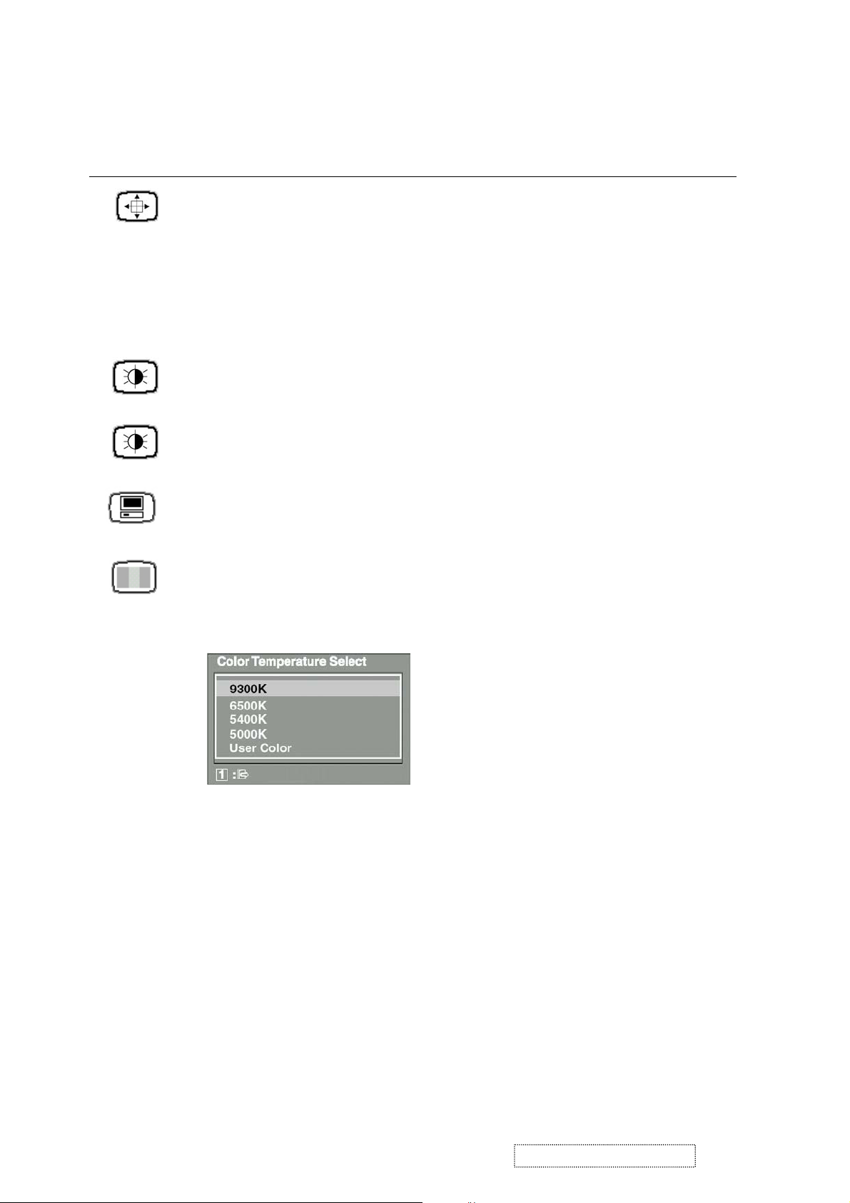
Color Adjust
color temperatures and
provides several color adjustment modes: preset
RGB
which allows you to adjust red (R),
green (G), and blue (B) separately. The factory setting for this
product is 6500K (6500 Kelvin).
9300K
— Adds blue to the screen image for cooler white (used
in most office settings with fluorescent lighting).
6500K
— Adds red to the screen image for warmer white and
richer red.
5400K
5000K
— Adds green to the screen image for a darker color.
— Adds blue and green to the screen image for a darker
color.
User Color
and blue (B)
To select color (R, G or B) press button [2].
1
To adjust selected color, press ▲ or ▼.
2
ViewSonic Corporation Confidential
— Individual adjustments for red (R), green (G),
.
18
-
Do Not Copy VP201b/s-1
Control Explanation
Important
: If you select RECALL from the Main Menu when
the product is set to a Preset Timing Mode, colors return to the
6500K factory preset.
Information
displays the timing mode (video signal input)
coming from the graphics card in your computer. See your
graphic card’s user guide for instructions on changing the
resolution and refresh rate (vertical frequency).
NOTE:
VESA 1600 x 1200 @ 60 Hz (recommended) means
that the resolution is 1600 x 1200 and the refresh rate is 60
Hertz.
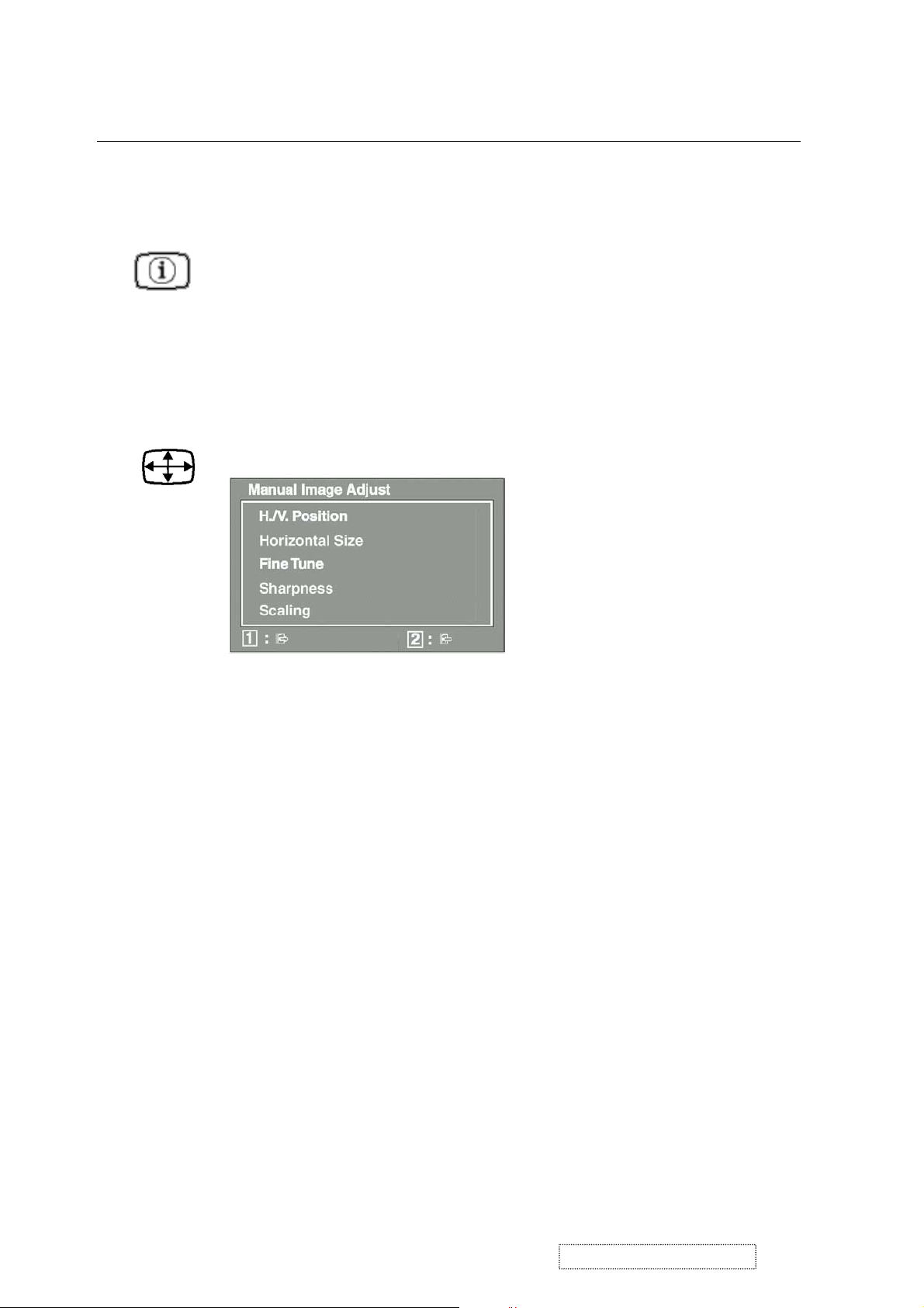
Manual Image Adjust
displays the Manual Image Adjust menu.
The
Manual Image Adjust
Horizontal Position
moves the screen image up or down.
Vertical Position
Horizontal Size
sharpens focus by aligning the illuminated text and/
Fine Tune
adjusts the width of the screen image.
moves the screen image left or right.
controls are explained below:
or graphic characters.
adjusts the clarity and focus of the screen image.
Sharpness
Scaling
adjusts the video input signal to the screen size other
than 1600 x 1200 using the following options.
adjusts the video signal so that the height and width of the
1:1
picture are the same.
adjusts the video signal to fill the screen.
Fill all
maintains the correct video signal proportions
Fill Aspect Ratio
for different resolutions.
ViewSonic Corporation Confidential
19
-
Do Not Copy VP201b/s-1
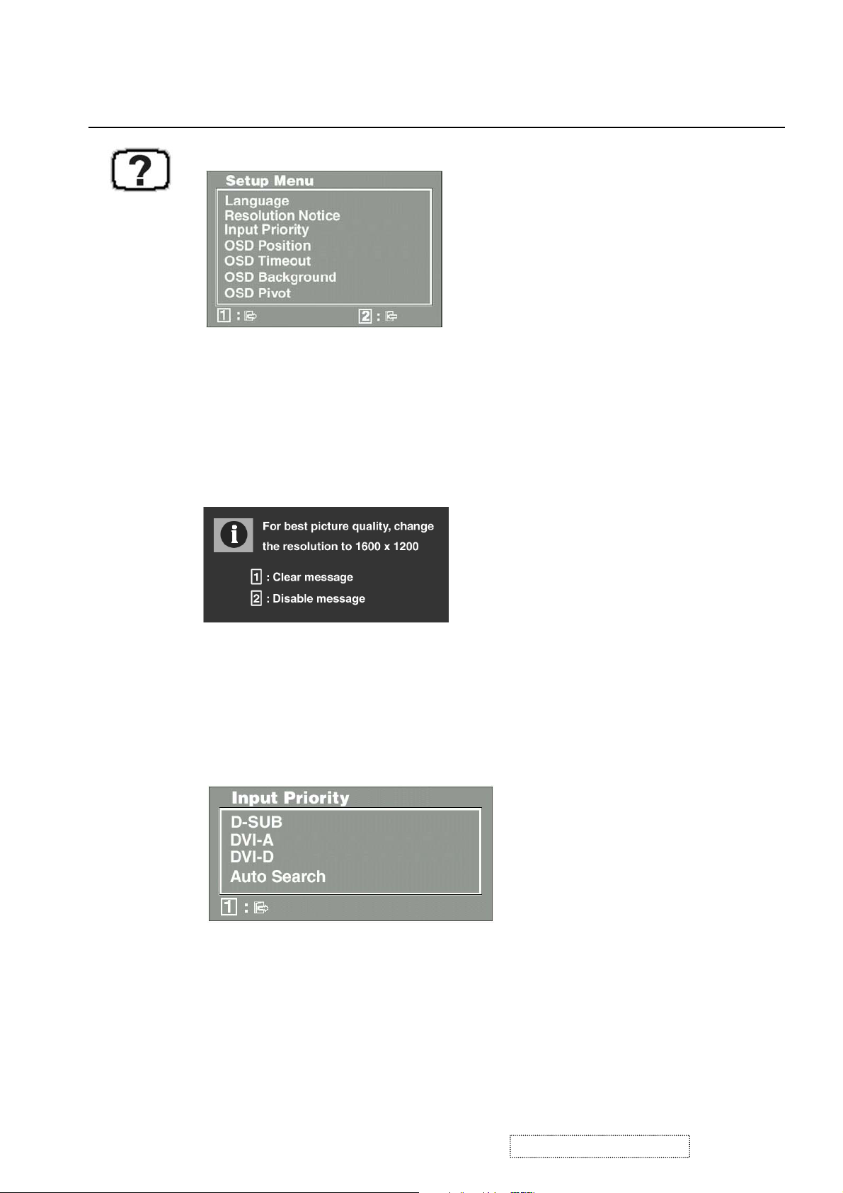
Control Explanation
Setup Menu
The
Setup Menu
Language
displays the menu shown below.
controls are explained below:
allows you to choose the language used in the menus
and control screens.
Resolution Notice
below.
displays the Resolution Notice menu shown
Resolution Notice
Input Priority
advises the optimal resolution to use.
If multiple computers will be connected to the display,
this function can be used to select which computer has priority
Depending on the selected Input Priority, the display will do a one
time detection for available inputs when first powered on.
allows you to move the on-screen display menus
OSD Position
and control screens.
sets the length of time an on-screen display
OSD Timeout
screen is displayed. For example, with a “15 second” setting, if
a control is not pushed within 15 seconds, the display screen
disappears.
ViewSonic Corporation Confidential
20
-
Do Not Copy VP201b/s-1

Control Explanation
OSD Background
allows you to turn the On-Screen-Display
background on or off.
OSD Pivot
This function is used to rotate the OSD menu,
when the display is changed from Landscape to Portrait mode.
Memory Recall
returns adjustments to the original factory
settings if the display is operating in a factory Preset Timing
Mode listed in this user guide.
Exception:
This control does not affect changes made with the
User Color control.
ViewSonic Corporation Confidential
21
-
Do Not Copy VP201b/s-1

4. Circuit Description
4.1 Power supply (DC/DC Converter):
4.1.1 IC251 BA9741 is a switching regulator controller that uses a PWM method. It is used for DC to DC
step-down conversion. It converts 24V DC into regulated and stable output voltages of 18V and 5V.
4.1.2 Regulator:
IC252 converts 5V into regulated and stable O/P 3.3V.
IC253 converts 5V into regulated and stable O/P 1.8V.
IC255 converts 5V into regulated and stable O/P 3.3V.
IC256 converts 5V into regulated and stable O/P 2.5V
4.2 DDC data select:
4.2.1 IC601 (AT24C02) saves D-SUB DDC data.
4.2.2 IC604 (AT24C02) saves DVI-D, DDC data.
4.2.3 IC605 (AT24C02) saves DVI-A, DDC data.
4.3 D-sub and DVI-A signal select
The VP231wb is equipped with two analog signal inputs: D-sub and DVI-A. The user may only choose
to display the signal from one of these ports: D-sub or DVI-A.
IC607 (AD8186) is a R, G, B signal switch IC. If the control signal (RGBSEL) is high, the device will
display the DVI-A signal. If the control signal (RGBSEL) is low, the device will display the D-sub signal.
4.4 Scalar
The gm1601H is a dual channel graphics and video processing IC for Liquid Crystal Display (LCD) monitors and
televisions incorporating Picture in Picture, up to WUXGA output resolutions. The gm1601H provides all key IC
functions required for image capture, processing and display timing control. On-chip functions include a high
speed triple-ADC and PLL, Ultra-Reliable DVI receiver, high quality zoom, and shrink scaling engines, Motion
Adaptive De-interlacing (MADI), Low Angle Diagonal Interpolation (LADI), an on-screen display (OSD)
controller, a 100MHz on-chip X186 micro-controller (OCM), and a selectable double side TTL or dual channel
LVDS transmitter for interface to displays.
4.5 USB(VP201s/b only)
IC951(USB20H04) is a 4-Port USB 2.0 Hub controller. It is compliant with the USB 2.0 specification,
enables bus-powered Hi-Speed hub design, and is compatible with On-The-Go (OTG) USB devices.
It is equipped with a serial interface for configuration from EEPROM or micro-controller when the default
settings are not used. Includes integrated termination and pull-up/pull-down resistors, as well as internal short
circuit protection of DP and DM lines. Supports individual or gangedover-current protection and power control.
ViewSonic Corporation Confidential
22
-
Do Not Copy VP201b/s-1

5. Adjustment Procedure
5.1 General.
1. All specifications must be met over line voltage range of 90V
AC
to 264V
AC
50Hz / 60Hz, unless otherwise
specified.
2. Operating temperature range is 0
o
C to 40oC with a relative humidity of 10% or less to 80%.
3. The monitor must be operational in a usable state within 30 minutes after turn-on.
4. All signal levels are measured assuming termination at the monitor’s input jacks or in its characteristic
impedance.
5. All controls must have excess range (no control may be left at an end stop when proper alignment is
completed).
6. The monitor is not required to meet specs under the following circumstances, but must tolerate without
damage to the LCD or circuits any sequence or combination of: Power on and off, signal on and off,
erratic or incorrect frequency, noisy inputs, any possible combination of unplugging of power or
signal cables, or any setting of user accessible controls. Likewise, the monitor should survive
extended periods of operation with line voltage reduced below the specified minimum.
7. An isolation transformer should be used when performing alignment and tests. Portions of the
power supply board are hot ground. The remaining boards are cold ground.
8. Ambient condition:
8.1 Illumination: In usual inspection of electric performance and mechanical performance, it shall be 150 ~
260lux.
8.2 Environmental noise: Less than 60dB.
8.3 Interference of EMI: The inspection shall be carried out in a place where the set is not disturbed by
excessive external electric waves or magnetic fields.
8.4 Temperature: 24 ± 2
o
C.
8.5 Humidity: 65 ± 20%.
ViewSonic Corporation Confidential
23
-
Do Not Copy VP201b/s-1
 Loading...