

Page 1

Service Manual
ViewSonic VP201b/s-1
Model No.
VLCDS26064-2W/-4W
20" Color TFT LCD Display
ViewSonic
(VP201b/s-1_SM_685 Rev. 1d May. 2005)
381 Brea Canyon Road, Walnut, California 91789 USA - (800) 888-8583
Page 2
Copyright
Copyright
2005 by ViewSonic Corporation. All rights reserved. No part of this publication may be
¤
reproduced, transmitted, transcribed, stored in a retrieval system, or translated into any language or
computer language, in any form or by any means, electronic, mechanical, magnetic, optical, chemical,
manual or otherwise, without the prior written permission of ViewSonic Corporation.
Disclaimer
ViewSonic makes no representations or warranties, either expressed or implied, with respect to the
contents hereof and specifically disclaims any warranty of merchantability or fitness for any particular
purpose. Further, ViewSonic reserves the right to revise this publication and to make changes from time
to time in the contents hereof without obligation of ViewSonic to notify any person of such revision or
changes.
Trademarks
Optiquest is a registered trademark of ViewSonic Corporation.
ViewSonic is a registered trademark of ViewSonic Corporation.
All other trademarks used within this document are the property of their respective owners.
Revision History
1a
1b
1c
1d
ECR Number
08/28/03
25/03/04
03/09/05
05/19/05
4923
5321
Initial Release
Panel Change LG U04 Panel 16ms DCN-3773
Scalar Change to GM1601
Panel change form: LG U04 Panel 16ms to AUO M201UN02 V3 16ms
Description of Changes
EditorRevision SM Editing Date
F. Fan
A. Lu
A. Lu
A. Lu
ViewSonic Corporation Confidential
i
-
Do Not Copy VP201b/s-1
Page 3

TABLE OF CONTENTS
1. Precautions and Safety Notices
2. Specification
3. Front Panel Function Control Description
4. Circuit Description
5. Adjustment Procedure
6. Troubleshooting Flow Chart
7. Recommended Spare Parts List
8. Exploded Diagram and Spare Parts List
9. Block Diagram
10. Schematic Diagrams
11. PCB Layout Diagrams
1
3
12
18
19
37
40
58
60
61
68
ViewSonic Corporation Confidential
ii
-
Do Not Copy VP201b/s-1
Page 4

1. Precautions and Safety Notices
1. Appropriate Operation
(1) Turn off the product before cleaning.
(2) Use only a dry soft cloth when cleaning the LCD panel surface.
(3) Use a soft cloth soaked with mild detergent to clean the display housing.
(4) Use only a high quality, safety approved AC/DC power cord.
(5) Disconnect the power plug from the AC outlet if the product will not be used for a long period of time.
(6) If smoke, abnormal noise, or strange odor is present, immediately switch the LCD display off.
(7) Do not touch the LCD panel surface with sharp or hard objects.
(8) Do not place heavy objects on the LCD display, video cable, or power cord.
(9) Do not use abrasive cleaners, waxes or solvents for your cleaning.
(10) Do not operate the product under the following conditions:
- Extremely hot, cold or humid environment.
- Areas containing excessive dust and dirt.
- Near any appliance generating a strong magnetic field.
- In direct sunlight.
2. Caution
No modification of any circuit should be attempted. Service work should only be performed after you are thoroughly familiar
with all of the following safety checks and servicing guidelines.
3. Safety Check
Care should be taken while servicing this LCD display. Because of the high voltage used in the inverter circuit, the voltage is
exposed in such areas as the associated transformer circuits.
4. LCD Module Handling Precautions
4.1 Handling Precautions
(1) Since front polarizer is easily damaged, pay attention not to scratch it.
(2) Be sure to turn off power supply when connecting or disconnecting input connector.
(3) Wipe off water drops immediately. Long contact with water may cause discoloration or spots.
(4) When the panel surface is soiled, wipe it with absorbent cotton or other soft cloth.
(5) Since the panel is made of glass, it may break or crack if dropped or bumped on hard surface.
(6) Since CMOS LSI is used in this module, take care of static electricity and ensure human earth when handling.
(7) Do not open or modify the Module Assembly.
(8) Do not press the reflector sheet at the back of the module in any direction.
(9) In the event that a Module must be put back into the packing container slot after it was taken out of the
container, do not press the center of the CCFL Reflector edge. Instead, press at the far ends of the
CFL Reflector edge softly. Otherwise the TFT Module may be damaged.
(10) At the insertion or removal of the Signal Interface Connector, be sure not to rotate or tilt the Interface
Connector of the TFT Module.
ViewSonic Corporation Confidential
1
-
Do Not Copy VP201b/s-1
Page 5

(11) After installation of the TFT Module into an enclosure (LCD monitor housing, for example), do not twist or
bend the TFT Module even momentarily. When designing the enclosure, it should be taken into consideration
that no bending/twisting forces may be applied to the TFT Module from outside. Otherwise the TFT Module
may be damaged.
(12) The cold cathode fluorescent lamp in the LCD contains a small amount of mercury. Please follow local
ordinances or regulations for disposal.
(13) The LCD module contains a small amount of materials having no flammability grade. The LCD module
should be supplied with power that complies with the requirements of Limited Power Source
(IEC60950 or UL1950), or an exemption should be applied for.
(14) The LCD module is designed so that the CCFL in it is supplied by a Limited Current Circuit (IEC60950
or UL1950). Do not connect the CCFL to a Hazardous Voltage Circuit.
ViewSonic Corporation Confidential
2
-
Do Not Copy VP201b/s-1
Page 6
2. Specification
A. General specification:
1. General specification:
LCD panel suppliers: AUO: M201UN02 V.3
LCD panel specification:
Input signals: a. Analog R / G / B (0.7Vp-p/75 ohm) Positive.
Input connector: a. Analog D-sub 15pin x 1.
Output connector: a. USB down stream x 4.(VP201s/b only)
Display data channel: DDC2B.
Signal frequency range: a. Horizontal:
a. Panel size: 20.1-inch (viewable).
b. Driver element: a - Si TFT active matrix.
c. Effective display area: 408.0 (H) X 306.0 (V) mm.
d. Pixel pitch: 0.255 (H) X 0.255 (V) mm.
e. Max. resolution: UXGA (1600X1280 pixel).
f. Display color: 16.7M colors (R, G, B 8-bit data).
g. Response time:
LG: 16 ms. (Typical)
AUO: 16 ms (Typical)
h. Color filter arrangement: R/G/B vertical stripe.
i. Black light: Edge – light type with 6CCFLs.
j. Contrast ratio:
LG: 400:1
AUO: 700:1
k. Luminance: 250cd/m2 (Typical).
l. Luminance variation: 1.54 (MAX.). (Note.1)
m. Viewing angle (CR >10): Horizontal: 170
b. Digital R /G / B DVI rev. 1.0 (TMDS single link)
c. H & V separate Sync: TTL level; Polarity: Positive or Negative.
d. H & V composite Sync: TTL level; Polarity: Positive or Negative.
e. SOG (Sync level 0.3Vp-p).
b. Digital DVI-I 29 pin x 1. (Analog + Digital)
c. USB up stream x1.(VP201s/b only)
a-1. Analog: 30KHz ~ 92KHz.
a-2. Digital: 30KHz ~ 92KHz.
b. Vertical: 50Hz ~ 85*
1
Hz.
o
, Vertical: 170o.
*Note:
When the resolution is set to 1600x1200, the maximum vertical
refresh rate is: Analog input: 60 Hz.
Digital input: 60 Hz.
c. Pixel clock:
c-1. Analog: 165MHz.
c-2. Digital: 165MHz.
d. Non-interlaced.
Resolution: 1600x1200. (UXGA)
Power supply: AC Input Range:
Less then 50Ap. For 115VAC. Inrush current
Less then 100Ap. For 230V
Power Consumption:
Less then 73W. On mode.
Less then 4W. Active off mode.
Less then 2W. DC power off.
AC 90 to 264V, 50/60Hz ± 3Hz,
1.5A.
.
AC
ViewSonic Corporation Confidential
3
-
Do Not Copy VP201b/s-1
Page 7
b
2. Physical specification:
Overall dimension:
Mechanical adjustment:
Packaging: a. Carton dimension:
Accessories: Power cable 1.8m.
3. Regulatory & Standard certification.
Regulatory standards UL, cUL, FCC-B, CB, CE, ENERGY, NOM, TUV/GS, TUV ERGO (covers
a. Height: 480.55mm.
b. Width: 448.00mm.
c. Depth: 266.65mm.
a. Net weight: 8.5kg. Weight:
b. Gross weight: 11.2kg.
a. Tilt: +25o ~ -5o.
b. Swivel:
c. Height adjust: 110mm.
d. Pivot: 90
± 45
o
o
.
.
a. Height: 494mm.
b. Width: 345mm.
c. Depth: 560mm.
User guide (English).
CD ROM.
Warranty card.
HD15 - HD15 cable.
DVI (D) – DVI (D) cable.
ISO13406-2 & MPRII), TCO’03(for VP201s/VP2000s), TCO99 (for VP201
NEMKO, SEMKO, DEMKO, FIMKO, GOST-R + 20 ORIGINAL COPIES
HYGIENIC, (SASO), PCBC, VCCI, BSMI, CCC, (PSB), (C-TICK), TUV-S
),
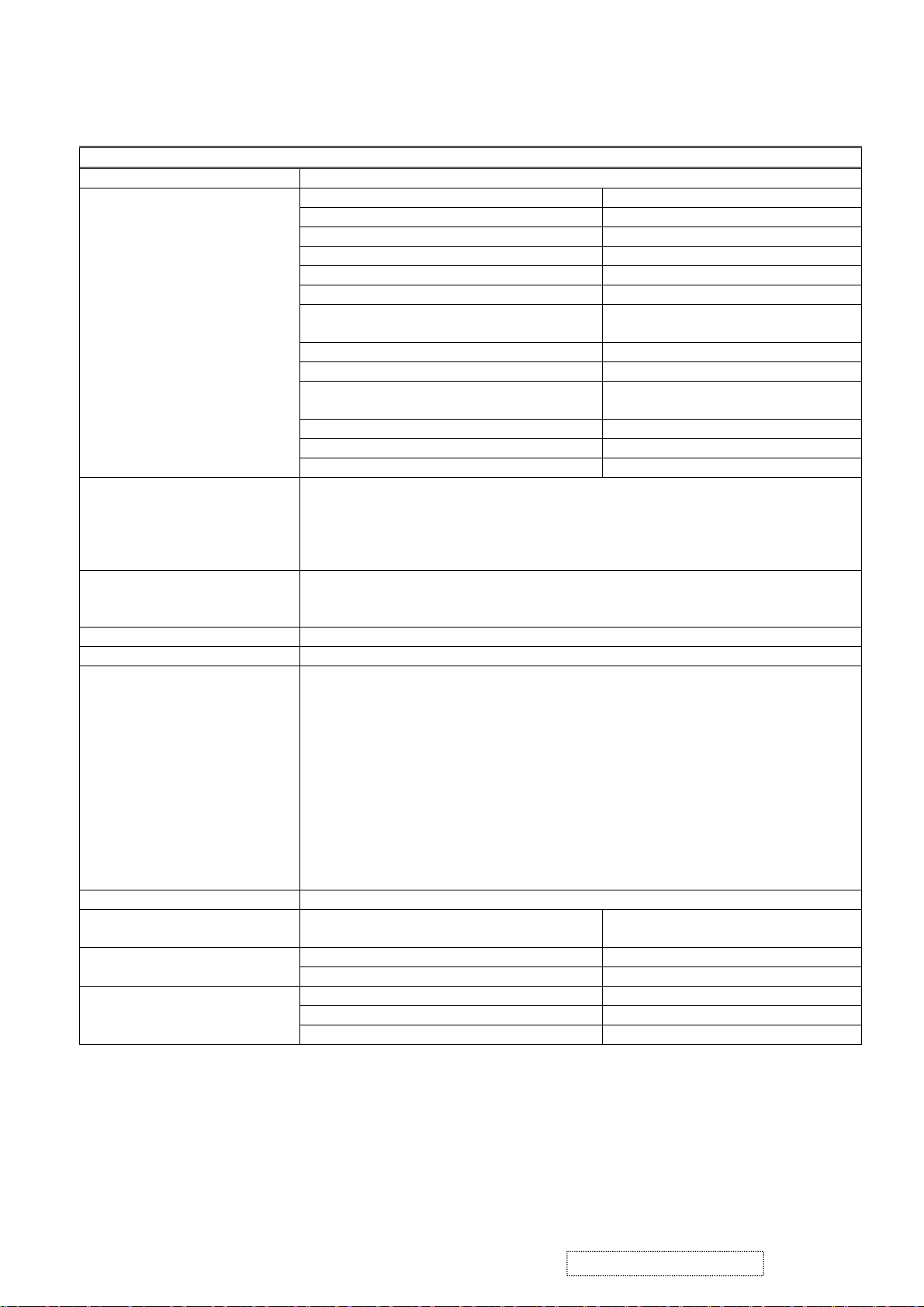
Note.1: Luminance variation:
50%90%
L = 408mm / W = 306mm
FIG.1 Luminance test points
10%
10%
50%
90%
BU =
MAX. Luminance in 9 point (1 ~ 9)
1.54
MIN. Luminance in 9 point (1 ~ 9)
ViewSonic Corporation Confidential
4
-
Do Not Copy VP201b/s-1
Page 8

B. OSD Menu Functions
1. Interface board function test.
1.1 Function keys: Power, 1, ▲, ▼, 2.
1.2 Basic function check.
1.2.1 Input 1600x1200 / 60Hz, cross-hatch reverse pattern.
1.2.2 Push “1” & “2” key, select Auto image adjust, Contrast, Brightness, Input select, Color,
Manual image adjust, Setup menu, Memory recall function.
1.2.3 Push “▲” or “▼” key check Contrast, Brightness, Input select, Color, H/V position, H size,
Fine tune, Sharpness, Scaling Language Select, OSD Position OSD Timeout, OSD
Background functions.
1.2.4 Push “2” to cycle among Analog / DVI-A / DVI-D signals.
1.2.5 When the OSD is not active, the “▲ ” and “▼” buttons increase/decrease Contrast or
Brightness.
2. Interface power test.
2.1 The test point:
2.1.1 TP251 = NA.
2.1.2 TP252 = 5V ± 5%.
2.1.3 TP253 = 18V ± 5%.
3. OSD function.
Auto Image Adjust
2
Contrast/Brightness: Contrast, Brightness.
Input Select: D-Sub, DVI-A, DVI-D.
Color Adjust: SRBG, 9300K, 6500K (default), 5400K, 5000K, User Color (R, G, B).
Information: Resolution, Horizontal Frequency, Vertical Frequency, Model Number, Serial Number,
Web Site.
Manual Image Adjust: H. / V. Position
Screen, Fill Aspect Ratio
2
(H. Position, V. Position), H. Size2, Fine Tune2, Scaling
4
, 1:1).
Setup Menu:
Language:
English, French, German, Spanish, Italian, Finnish, Japanese, Traditional Chinese, Simplified Chinese.
Resolution Notice: Enable, Disable.
Input Priority: D-Sub, DVI-A, DVI-D, Auto Search.
OSD Position: H. Position, V. Position.
OSD Timeout: 5SEC, 15SEC, 30SEC, 60SEC
OSD Background: On, Off.
Memory Recall
Notes:
2
These functions are not available in Digital mode; the item is faded out and can’t be
When auto tuning, the image should not go blank.
3
These functions are not available in 1600x1200 mode; the item is faded out and can’t be
4
When the input signal’s aspect ratio is 4:3, the “Fill Aspect ratio” function yields the same
result as “Fill Screen”.
3
(Fill
selected.
selected.
ViewSonic Corporation Confidential
5
-
Do Not Copy VP201b/s-1
Page 9

C. Image Calibration
1. Video alignment.
Initial Settings
1.1 Set contrast to 70%
and brightness to 100%.
1.2 Input a 640x480 / 60Hz, 5-block (5-MOSAIC) pattern (input level 100IRE 0.7Vp-p), then
activate the White Balance function.
Set SRBG/9300K / 6500K / 5400K / 5000K, R G B Gain as shown below:
sRGB 9300K 6500K 5400K 5000K
Analog DVI Analog DVI Analog DVI Analog DVI Analog DVI
R Gain 255 255 255 255 255 255 255 255 255 255
G Gain 255 255 255 255 255 255 255 255 255 255
B Gain 255 255 255 255 255 255 255 255 255 255
2. 9300K alignment:
1.2.1 Input 1600x1200 / 60Hz & full white pattern at 100IRE.
1.2.2 Adjust R, G, and B Gain to meet following chromaticity spec:
9300K → x = 0.283 ± 0.005, y = 0.298 ± 0.005, Y > 150cd/m
2
(Both analog & DVI).
3. 6500K alignment:
1.3.1 Input 1600x1200 / 60Hz & full white pattern at 100IRE.
1.3.2 Adjust R, G and B Gain to meet following chromaticity spec:
6500°K → x = 0.313 ±0.005, y = 0.329 ± 0.005, Y > 200cd/m
2
(Both analog & DVI).
4. 5400K alignment:
1.4.1 Input 1600x1200 / 60Hz & full white pattern at 100IRE.
1.4.2 Adjust R, G, and B Gain to meet following chromaticity spec:
5400K → x = 0.335 ± 0.005, y = 0.350 ± 0.005, Y > 180cd/m
2
(Both analog & DVI).
5. 5000K alignment:
1.5.1 Input 1600x1200 / 60Hz & full white pattern at 100IRE.
1.5.2 Adjust R, G and B Gain to meet following chromaticity spec:
6. sRGB alignment:
1.6.1 Input 1600x1200 / 60Hz & full white pattern at 100IRE.
1.6.2 Adjust R, G and B Gain to meet following chromaticity spec:
7. 64 grays and 16 grays pattern check:
sRGB → x = 0.313 ±0.005, y = 0.329 ± 0.005, Y > 200cd/m
2
(Both analog & DVI).
7.1 Input a 1600x1200 / 60Hz, 64 gray-level pattern at 100IRE, with brightness set to 100% and
contrast set to 70%.
7.2 Verify that under the 9300K / 6500K / 5400K / 5000K settings, no more than 2 of the 64
grays are saturated.
7.3 Input a 1600x1200 / 60Hz, 16 gray-level pattern at 100IRE, with brightness set to 100% and
contrast set to 100%.
7.4 Verify that under the 9300K / 6500K / 5400K / 5000K settings, no more than 4 of the 16
grays are saturated.
ViewSonic Corporation Confidential
6
-
Do Not Copy VP201b/s-1
Page 10
D. Image test
1. Picture size & position.
1.1 Picture size.
Input analog timing modes 1 ~28 and DVI timing modes 1 ~ 28:
H-size: 408mm
V-size: 306mm
± 1mm.
± 1mm.
g1
(Extra 640x350)
1.2 Screen center.
a. 1600x1200: H ± 1mm, V ± 1mm.
b. Other modes: H ± 1.5mm, V ± 1mm.
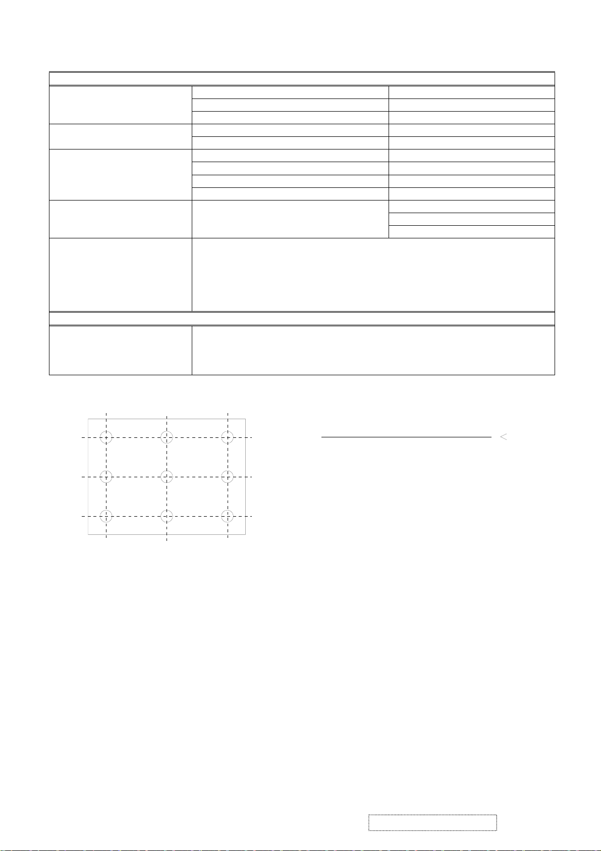
1.3 Picture position (refer to FIG.2).
H-position:
V-position:
︱g3-g4︱ ≦ 1.5mm.
︱g1-g2︱ ≦ 1.5mm.
g3
g2
g4
408mm
FIG. 2
2. Luminance test.
2.1 Input a 1600x1200 / 60Hz full white pattern at 100IRE with brightness set to 100% and contrast set to
70%.
Color temperature x y
Y (Luminance)
Analog DVI
sRGB 0.313 ± 0.01 0.329 ± 0.01 >200 nit >200 nit
9300K 0.283 ± 0.01 0.298 ± 0.01 >150 nit >150 nit
6500K 0.313 ± 0.01 0.329 ± 0.01 >200 nit >200 nit
5400K 0.335 ± 0.01 0.350 ± 0.01 >180 nit >180 nit
5000K 0.346 ± 0.01 0.359 ± 0.01 >180 nit >180 nit
2.2 Input a1600x1200 / 60Hz full white pattern at 100IRE with brightness set to 100% and contrast set to
100%.
Color temperature
Y (Luminance)
Analog DVI
9300K >220 nit >220 nit
6500K >220 nit >220 nit
5400K >220 nit >220 nit
5000K >220 nit >220 nit
3. Picture performance test.
3.1 Picture quality:
Test pattern signal The following image faults shall not be conspicuous:
1 100IRE white raster pattern Seam, Noise, Beat, Flicker
2 Cross hatch pattern Ringing, Overshoot, Smear, V-jitter, H-jitter
3 Color bar Color distortion, Noise, Beat, Color tangent
4 Gray scale (16 steps) Noise, Beat, Gamma distortion
5 1 dot ON / 1 dot OFF pattern Noise, Flicker
6 40IRE gray raster Noise, Beat, Gamma distortion
3.2 DVI performance test.
3.2.1 Test equipment:
a. VG828 digital pattern generator.
b. “TTL” DVI-D single link cable.
3.2.2 Test conditions:
a. Resolution: 1600x1200; refresh rate: 75KHz vertical / 60Hz horizontal.
306mm
b. 16, 32, 64, and 256-level horizontal gray scales..
c. 16, 32, 64, and 256-level vertical gray scales..
ViewSonic Corporation Confidential
7
-
Do Not Copy VP201b/s-1
Page 11
4. Shortcut keys and factory presets
4.1 Shortcut keys: Press the following keys to adjust settings directly, when the OSD is not active.
[
1]. Main Menu.
[2].
Select next input. (Sequence: D-SUB
→ DVI-A → DVI-D)
[UP] or [DOWN] arrow. Directly activate the Contrast menu. Switch to Brightness menu by
pushing button [
2].
[UP] + [DOWN] arrows. Recall either Contrast or Brightness settings while the Contrast or
Brightness adjustment OSD is active, or recall both Contrast and
Brightness settings when the OSD is not active.
[1] + [2].
Toggle 720x400 and 640x400 mode when input 720x400 or 640x400
mode.
[1] + [UP] + [DOWN]. White Balance (press and hold for 5 seconds).
[2] + [UP] + [DOWN]. Video Mirror Function
[1] + [DOWN]. Power Lock / Power Unlock (press and hold for 10 seconds).
[1] + [UP]. OSD Lock / OSD Unlock (press and hold for 10 seconds).
DC-Power + [2] + [UP]. Copy EDID to E
2
PROM.
DC-Power + [1]. Factory mode. (Burn in mode on)
DC-Power + [2] + [DOWN]. Burn in mode on.
DC-Power + [UP] + [DOWN]. Burn in mode off.
DC-Power + [2]. All mode recall.
AC-Power on. Enter ISP mode.
4.2 All mode recall settings:
Contrast 70%.
Brightness 100%.
Color Temperature 6500K.
Scaling Full Screen.
Input Priority Auto Search.
OSD H. Position 50%.
OSD V. Position 50%.
OSD Time Out 15 Sec
OSD Background On
Resolution Notice Enabled
720x400/640x400 720x400
User color. 50%.
Language. English.
Clear burn in mode.
Clear user mode table.
4.3 Factory shipment settings:
4.3.1 Main power switch: Off.
4.3.2 AC power button: Off.
4.3.3 Others settings same as “All mode recall” settings.
5. Power management tests.
5.1 Power consumption test table:
Monitor status LED color Video signal Power consumption Recover time
Normal / Unstable / Warning Green Active <73W
Power save Amber Blank <4W 5sec
Aging
Note
NA <73W
DC power off Off NA <2W
AC power off Off NA -
See note:
Amber (0.5sec) → Green (0.5sec) → Amber (0.5sec) → Green (0.5sec)… continuously.
6. DDC test.
6.1 DDC / EDID specification compliance requirement.
The data that is transmitted shall be stored in the monitor in non-volatile memory, which is a
requirement of the VESA EDID version 3.0 standard.
ViewSonic Corporation Confidential
8
-
Do Not Copy VP201b/s-1
Page 12
6.2 IC954 EEPROM data see Appendix-B item a.6.3 For the EDID data see Appendix B. VP2000s
analog & DVI-A are the same as item h. For the DVI-D input 1 see item i.
7. USB test (VP201s/b only)
7.1 Use a USB test hub such as “UPT2 USB2.0 8-port tester” to test USB up stream and down stream
transfers. Each port must pass the test.
7.2 Use a PC to check the USB VID, which should be
0543, and the PID, which should be 1169.
7.3 For USB test settings see Appendix E.
8. For auto alignment, it is necessary to execute the auto image adjust command for 3 DOS modes (640x350,
720x400, 640x400).
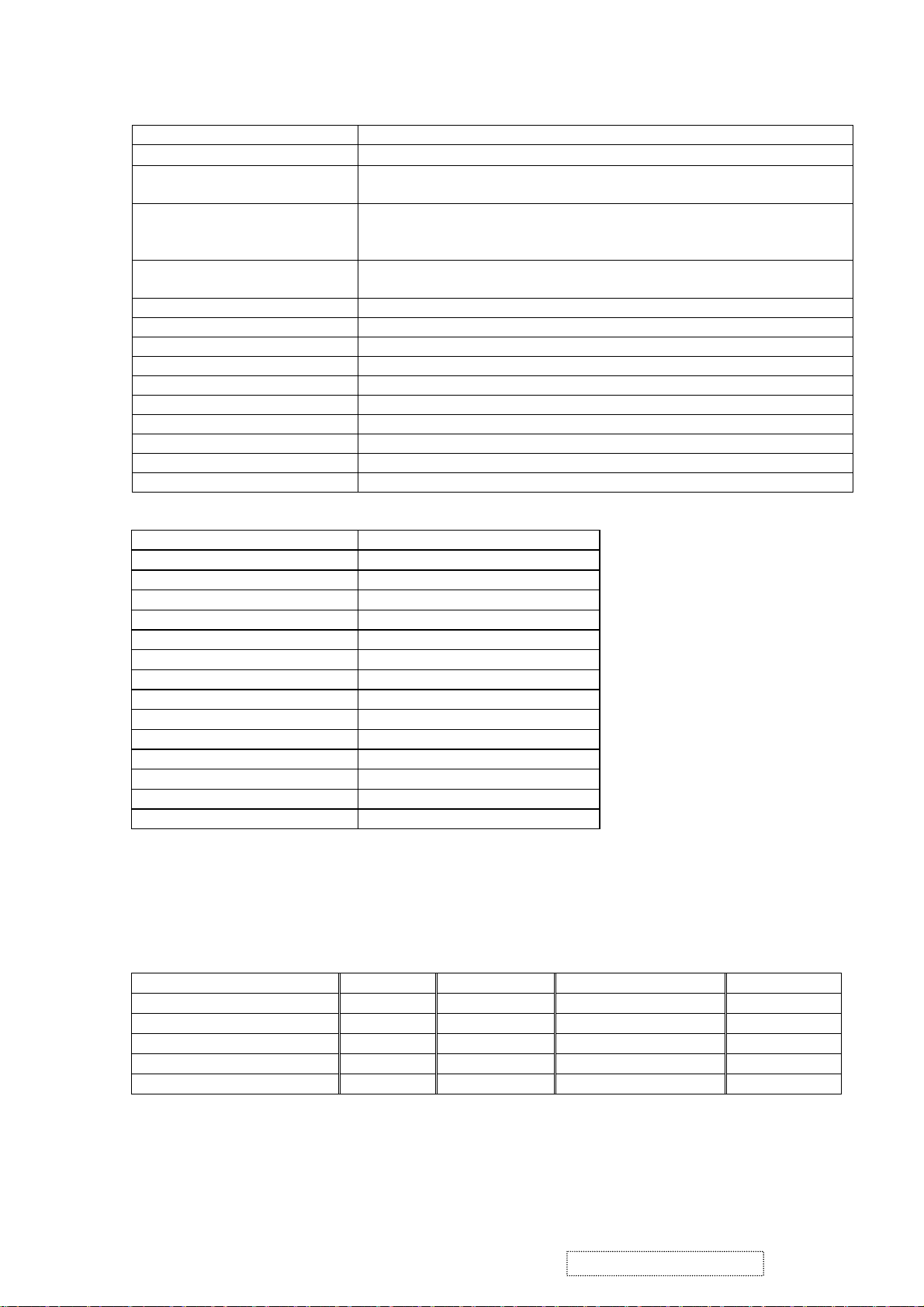
E. Analog and Digital timing chart.
Mode No. 1 2 3 4 5 6 7 8 9 10
TEXT
Mode Name
640 x
350
Horizontal Freq. 31.468 31.468 24.688 31.469 35.000 37.861 37.500 43.269 31.469
VGA
640 x
400
VESA
640 x
480
VESA
640 x
480
MAC
640 x
480
VESA
640 x
480
VESA
640 x
480
VESA
640 x
480
TEXT
720 x
400
VESA
800 x
600
35.156
Video clock Freq. 25.175 25.175 19.75 25.175 30.240 31.500 31.500 36.000 28.322 36.000
Sync. Polarity
+ - - - - - - - - +
H. total (Dots) 800 800 800 800 864 832 840 832 900 1024
H. sync. (Dots) 96 96 64 96 64 40 64 56 108 72
H. back porch (Dots) 48 48 80 48 96 128 120 80 54 128
H. active (Dots) 640 640 640 640 640 640 640 640 720 800
H. front porch (Dots) 16 16 16 16 64 24 16 56 18 24
Vertical Freq. (Hz) 70.087 70.087 49.673 59.940 66.667 72.809 75.000 85.008 70.087 56.250
Sync. Polarity
- + + - - - - - + +
V. total (Lines) 449 449 497 525 525 520 500 509 449 625
V. sync. (Lines) 2 2 4 2 3 3 3 3 2 2
V. back porch (Lines) 60 35 10 33 39 28 16 25 35 22
V. active
(Lines)
350 400 480 480 480 480 480 480 400 600
V. front porch (Lines) 37 12 3 10 3 9 1 1 12 1
ViewSonic Corporation Confidential
9
-
Do Not Copy VP201b/s-1
Page 13
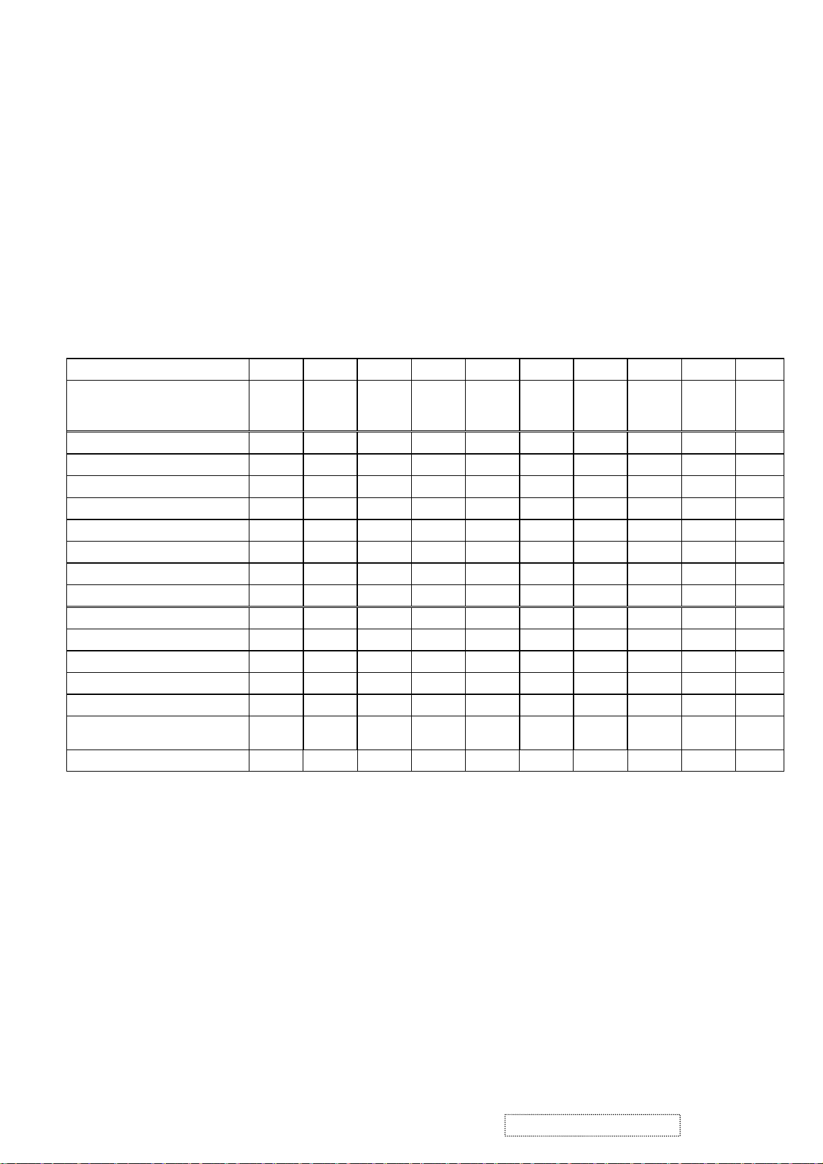
Mode No.
Mode Name
Horizontal Freq. (KHz) 37.879 48.077 46.875 53.674
Video clock Freq. 40.000 50.000 49.500 56.250 57.285 65.000 75.000 78.084 78.750 94.500
Sync. Polarity
H. total (Dots) 1056 1040 1056 1048 1152 1344 1328 1344 1312 1376
H. sync. (Dots) 128 120 80 64 64 136 136 136 96 96
H. back porch (Dots) 88 64 160 152 224 160 144 160 176 208
H. active (Dots) 800 800 800 800 832 1024 1024 1024 1024 1024
H. front porch (Dots) 40 56 16 32 32 24 24 24 16 48
Vertical Freq. (Hz) 60.317 72.188 75.000 85.061 74.553 60.004 70.069 72.082 75.029 84.997
Sync. Polarity
V. total (Lines) 628 666 625 631 667 807 806 806 800 808
V. sync. (Lines) 4 6 3 3 3 6 6 6 3 3
V. back porch (Lines) 23 23 21 27 37 29 29 29 28 38
V. active
(Lines)
V. front porch (Lines) 1 37 1 1 3 3 3 3 1 1
11 12 13 14 15 16 17 18 19 20
VESA
800 x
600
+ + + + - - - - + +
+ + + + - - - - + +
600 600 600 600 624 768 768 768 768 768
VESA
800 x
600
VESA
800 x
600
VESA
800 x
600
MAC
832 x
624
49.727
VESA
1024 x
768
48.363
VESA
1024 x
768
56.476 58.099
XGA
1024 x
768
VESA
1024 x
768
60.023 68.677
VESA
1024 x
768
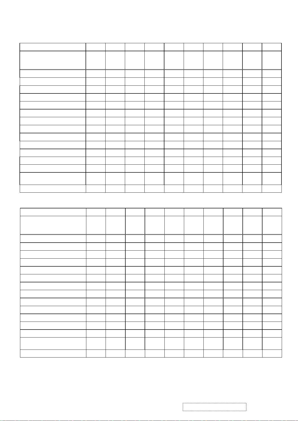
Mode No.
Mode Name
Horizontal Freq. (KHz) 68.681 60.000 75.231 63.981 79.976 91.146
Video clock Freq. 100.00 108.00 130.00 108.00 135.00 157.50 74.250 162.00
Sync. Polarity
H. total (Dots) 1456 1800 1728 1688 1688 1728 1650 2160
H. sync. (Dots) 128 112 136 112 144 160 40 192
H. back porch (Dots) 144 312 224 248 248 224 270 304
H. active (Dots) 1152 1280 1280 1280 1280 1280 1280 1600
H. front porch (Dots) 32 96 88 48 16 64 60 64
Vertical Freq. (Hz) 75.062 60.000 74.857 60.020 75.025 85.024 60.000 60.000
Sync. Polarity
V. total (Lines) 915 1000 1005 1066 1066 1072 750 1250
V. sync. (Lines) 3 3 4 3 3 3 5 3
V. back porch (Lines) 39 36 38 38 38 44 20 46
V. active
(Lines)
V. front porch (Lines) 3 1 3 1 1 1 5 1
21 22 23 24 25 26 27 28 29 30
APPLE
1152x
870
- + - + + + - +
- + + + + + - +
870 960 960 1024 1024 1024 720 1200
VESA
1280 x
960
VESA
1280 x
960
VESA
1280 x
1024
VESA
1280 x
1024
VESA
1280 x
1024
HDTV
1280 x
720
45.000
VESA
1600 x
1200
75.000
ViewSonic Corporation Confidential
10
-
Do Not Copy VP201b/s-1
Page 14

Appendix B: DDC contents.
a. 128 bytes of EDID code for VP201s analog.
b. 128 bytes of EDID code for VP201s digital.
0 1 2 3 4 5 6 7 8 9
0 00 FF FF FF FF FF FF 00 5A 63
10 18 0C 01 01 01 01 01 0F 01 03
20 0E 29 1F 78 2E 30 85 A6 56 4A
30 99 24 14 50 54 BF EF 80 A9 40
40 81 80 81 40 71 4F 01 01 01 01
50 01 01 01 01 48 3F 40 30 62 B0
60 32 40 40 C0 13 00 98 32 11 00
70 00 1E 00 00 00 FF 00 41 32 55
80 30 35 30 31 30 30 30 30 31 0A
90 00 00 00 FD 00 32 4B 1E 5C 11
100 00 0A 20 20 20 20 20 20 00 00
110 00 FC 00 56 50 32 30 31 73 0A
120 20 20 20 20 20 20 00 B0
0 1 2 3 4 5 6 7 8 9
0 00 FF FF FF FF FF FF 00 5A 63
10 18 0C 01 01 01 01 01 0F 01 03
20 80 29 1F 78 2E 30 85 A6 56 4A
30 99 24 14 50 54 BF EF 80 A9 40
40 81 80 81 40 71 4F 31 0A 01 01
50 01 01 01 01 48 3F 40 30 62 B0
60 32 40 40 C0 13 00 98 32 11 00
70 00 1E 00 00 00 FF 00 41 32 55
80 30 35 30 31 30 30 30 30 31 0A
90 00 00 00 FD 00 32 4B 1E 5C 11
100 00 0A 20 20 20 20 20 20 00 00
110 00 FC 00 56 50 32 30 31 73 0A
120 20 20 20 20 20 20 00 05
ViewSonic Corporation Confidential
11
-
Do Not Copy VP201b/s-1
Page 15

3. Front Panel Function Control Description
Adjusting the Screen Image
Use the buttons on the front control panel to display and adjust the OnView®
controls which display on the screen. The OnView controls are explained at the
of the next page.
top
Main Menu
with OnView controls
Front Control Panel
shown below in detail
Displays the Main Menu
or exits the control screen
and saves adjustments.
Scrolls through menu options and
adjusts the displayed control.
Also a shortcut to display the
Contrast adjustment control
screen.
Displays the control
screen for the highlighted
control.
Also toggles between two
controls on some
screens.
Also a shortcut to toggle
analog and digital connection.
Power light
Green = ON
Orange = Power
Saving
ViewSonic Corporation Confidential
12
Power
On/Off
-
Do Not Copy VP201b/s-1
Page 16

Do the following to adjust the screen image:
To display the Main Menu, press button [1].
1
NOTE:
All OnView menus and adjustment screens disappear automatically
after about 30 seconds.
To select a control you want to adjust, press ▲ or ▼ to scroll up or down the
2
Main Menu.
After the control is selected, press button [2].
3
To adjust the control, press the up ▲ or down ▼ buttons.
4
To save the adjustments and exit the menu, press button [1]
5
twice
.
The following tips may help you optimize your display:
• Adjust your computer's graphic card so that it outputs a video signal 1600 x
1200 @ 60 Hz to the LCD display. (Look for instructions on “changing the
refresh rate” in your graphic card's user guide.)
• If necessary, make small adjustments using H POSITION and V POSITION
until the screen image is completely visible
. (The black border around the
edge of the screen should barely touch the illuminated “active area” of the
LCD display.)
ViewSonic Corporation Confidential
13
-
Do Not Copy VP201b/s-1
Page 17
Main Menu Controls
Adjust the menu items shown below by using the up ▲ and down ▼ buttons.
Control Explanation
automatically sizes, centers, and fine tunes
Auto Image Adjust
the video signal to eliminate waviness and distortion.
Press the [2] button to obtain a sharper image.
NOTE: Auto Image Adjust works with most common video
cards. If this function does not work on your LCD display, then
lower the video refresh rate to 60 Hz and set the resolution to its
pre-set value.
Contrast
adjusts the difference between the image background
(black level) and the foreground (white level).
Brightness
Input Select
adjusts background black level of the screen image.
allows you to toggle between an analog and a
digital signal.
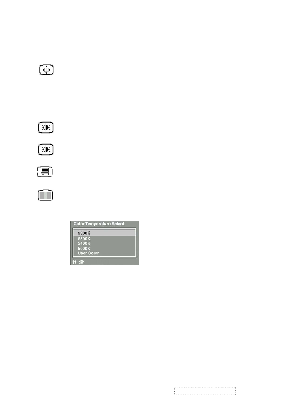
Color Adjust
color temperatures and
provides several color adjustment modes: preset
RGB
which allows you to adjust red (R),
green (G), and blue (B) separately. The factory setting for this
product is 6500K (6500 Kelvin).
9300K
— Adds blue to the screen image for cooler white (used
in most office settings with fluorescent lighting).
6500K
— Adds red to the screen image for warmer white and
richer red.
5400K
5000K
— Adds green to the screen image for a darker color.
— Adds blue and green to the screen image for a darker
color.
User Color
and blue (B)
To select color (R, G or B) press button [2].
1
To adjust selected color, press ▲ or ▼.
2
ViewSonic Corporation Confidential
— Individual adjustments for red (R), green (G),
.
14
-
Do Not Copy VP201b/s-1
Page 18
Control Explanation
Important
: If you select RECALL from the Main Menu when
the product is set to a Preset Timing Mode, colors return to the
6500K factory preset.
Information
displays the timing mode (video signal input)
coming from the graphics card in your computer. See your
graphic card’s user guide for instructions on changing the
resolution and refresh rate (vertical frequency).
NOTE:
VESA 1600 x 1200 @ 60 Hz (recommended) means
that the resolution is 1600 x 1200 and the refresh rate is 60
Hertz.
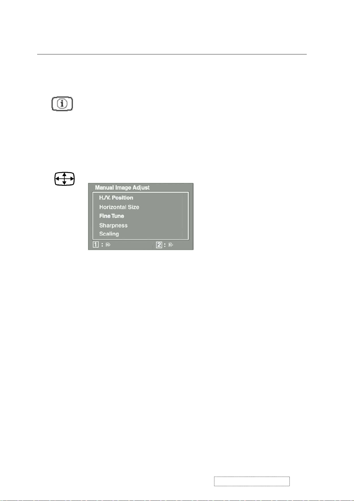
Manual Image Adjust
displays the Manual Image Adjust menu.
The
Manual Image Adjust
Horizontal Position
moves the screen image up or down.
Vertical Position
Horizontal Size
sharpens focus by aligning the illuminated text and/
Fine Tune
adjusts the width of the screen image.
moves the screen image left or right.
controls are explained below:
or graphic characters.
adjusts the clarity and focus of the screen image.
Sharpness
Scaling
adjusts the video input signal to the screen size other
than 1600 x 1200 using the following options.
adjusts the video signal so that the height and width of the
1:1
picture are the same.
adjusts the video signal to fill the screen.
Fill all
maintains the correct video signal proportions
Fill Aspect Ratio
for different resolutions.
ViewSonic Corporation Confidential
15
-
Do Not Copy VP201b/s-1
Page 19
Control Explanation
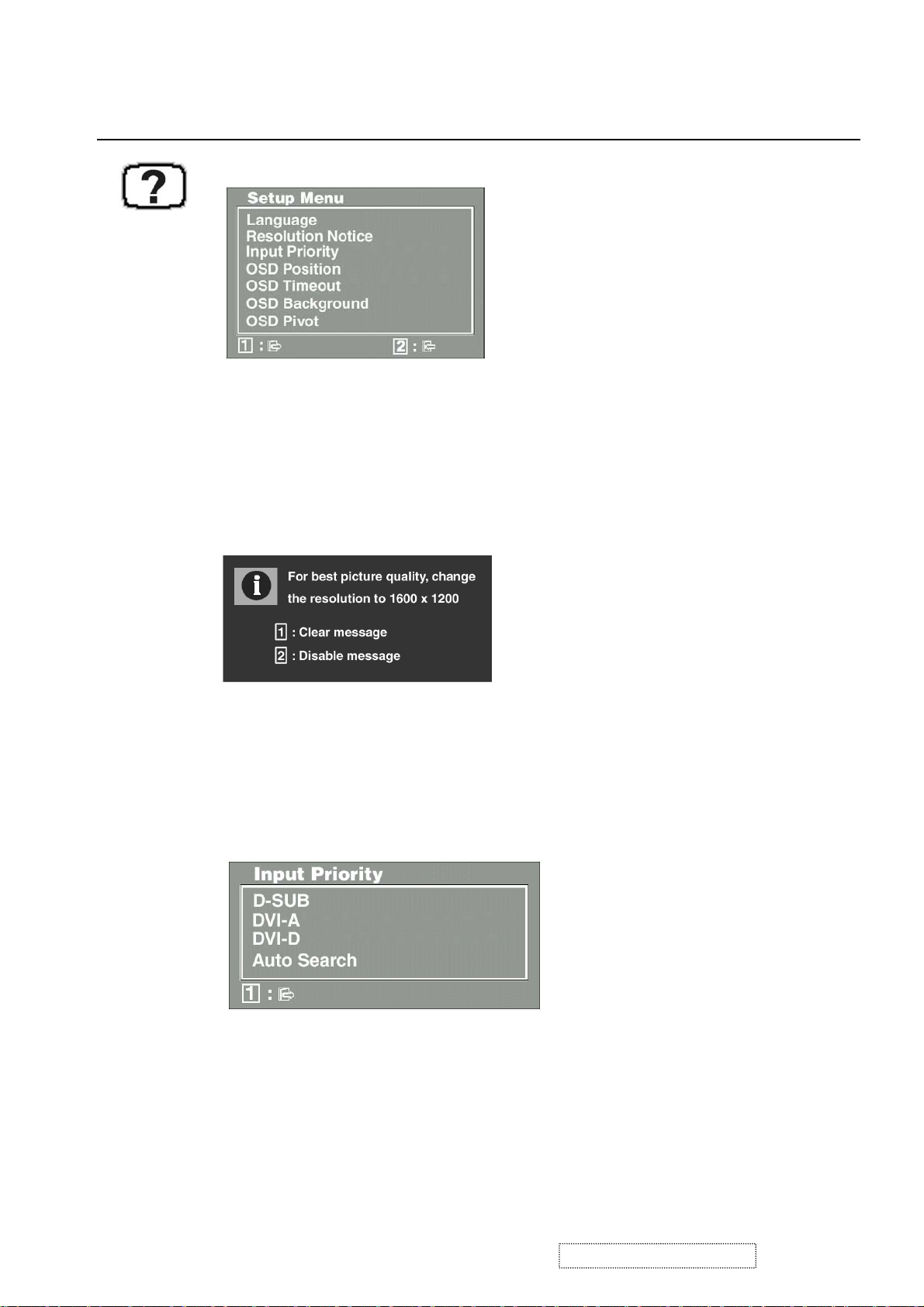
Setup Menu
The
Setup Menu
Language
displays the menu shown below.
controls are explained below:
allows you to choose the language used in the menus
and control screens.
Resolution Notice
below.
displays the Resolution Notice menu shown
Resolution Notice
Input Priority
advises the optimal resolution to use.
If multiple computers will be connected to the display,
this function can be used to select which computer has priority
Depending on the selected Input Priority, the display will do a one
time detection for available inputs when first powered on.
allows you to move the on-screen display menus
OSD Position
and control screens.
sets the length of time an on-screen display
OSD Timeout
screen is displayed. For example, with a “15 second” setting, if
a control is not pushed within 15 seconds, the display screen
disappears.
ViewSonic Corporation Confidential
16
-
Do Not Copy VP201b/s-1
Page 20

Control Explanation
OSD Background
allows you to turn the On-Screen-Display
background on or off.
OSD Pivot
This function is used to rotate the OSD menu,
when the display is changed from Landscape to Portrait mode.
Memory Recall
returns adjustments to the original factory
settings if the display is operating in a factory Preset Timing
Mode listed in this user guide.
Exception:
This control does not affect changes made with the
User Color control.
ViewSonic Corporation Confidential
17
-
Do Not Copy VP201b/s-1
Page 21

4. Circuit Description
4.1 Power supply (DC/DC Converter):
4.1.1 IC251 BA9741 is a switching regulator controller that uses a PWM method. It is used for DC to
DC step-down conversion. It converts 24V DC into regulated and stable output voltages of 18V
and 5V.
4.1.2 Regulator:
IC252 converts 5V into regulated and stable O/P 3.3V.
IC253 converts 5V into regulated and stable O/P 1.8V
IC255 converts 5V into regulated and stable O/P 3.3V.
IC256 converts 5V into regulated and stable O/P 2.5V.
4.2 DDC data select:
4.2.1 IC601 (AT24C02) saves D-SUB DDC data.
4.2.2 IC604 (AT24C02) saves DVI-D, DDC data.
4.2.3 IC605 (AT24C02) saves DVI-A, DDC data.
4.3 D-sub and DVI-A signal select
The VP201s is equipped with two analog signal inputs: D-sub and DVI-A. The user may only choose to
display the signal from one of these ports: D-sub or DVI-A.
IC607 (AD8186) is a R, G, B signal switch IC. If the control signal (RGBSEL) is high, the device will
display the DVI-A signal. If the control signal (RGBSEL) is low, the device will display the D-sub.
4.4 Scalar
The gm1601H is a dual channel graphics and video processing IC for Liquid Crystal Display (LCD) monitors and
televisions incorporating Picture in Picture, up to WUXGA output resolutions. The gm1601H provides all key IC
functions required for image capture, processing and display timing control. On-chip functions include a high speed
triple-ADC and PLL, Ultra-Reliable DVI receiver, high quality zoom, and shrink scaling engines, Motion Adaptive
De-interlacing (MADI), Low Angle Diagonal Interpolation (LADI), an on-screen display (OSD) controller, a 100MHz
on-chip X186 micro-controller (OCM), and a selectable double side TTL or dual channel LVDS transmitter for
interface to displays.
4.5 USB(VP201s/b only)
IC951(USB20H04) is a 4-Port USB 2.0 Hub controller. It is compliant with the USB 2.0 specification,
enables bus-powered Hi-Speed hub design, and is compatible with On-The-Go (OTG) USB devices. It is
equipped with a serial interface for configuration from EEPROM or micro-controller when the default
settings are not used. Includes integrated termination and pull-up/pull-down resistors, as well as internal
short circuit protection of DP and DM lines. Supports individual or ganged
over-current protection and power control.
ViewSonic Corporation Confidential
18
-
Do Not Copy VP201b/s-1
Page 22

5. Adjustment Procedure
5.1 General.
1. All specif ications must be met over line voltage range of 90VAC to 264V
50Hz / 60Hz, unless otherwise
AC
specified.
2. Operating temperature range is 0
o
C to 40oC with a relative humidity of 10% or less to 80%.
3. The monitor must be operational in a usable state within 30 minutes after turn-on.
4. All signal levels are measured assuming termination at the monitor’s input jacks or in its characteristic impedance.
5. All controls must have excess range (no control may be left at an end stop when proper alignment is completed).
6. The monitor is not required to meet specs under the following circumstances, but must tolerate without
damage to the LCD or circuits any sequence or combination of: Power on and off, signal on and off,
erratic or incorrect frequency, noisy inputs, any possible combination of unplugging of power or signal
cables, or any setting of user accessible controls. Likewise, the monitor should survive extended
periods of operation with line voltage reduced below the specified minimum.
7. An isolation transformer should be used when performing alignment and tests. Portions of the power
supply board are hot ground. The remaining boards are cold ground.
8. Ambient condition:
8.1 Illumination: In usual inspection of electric performance and mechanical performance, it shall be 150 ~
260lux.
8.2 Environmental noise: Less than 60dB.
8.3 Interference of EMI: The inspection shall be carried out in a place where the set is not disturbed by
excessive external electric waves or magnetic fields.
8.4 Temperature: 24 ± 2
o
C.
8.5 Humidity: 65 ± 20%.
ViewSonic Corporation Confidential
19
-
Do Not Copy VP201b/s-1
Page 23
5.2 Instrument alignment.
5.2.1 Adjustment procedure.
Input
D-SUB
Input
640x480 / 60Hz
Chross-hatch
Into Burn-in mode
Push “Down + 2 + DC power”
3 second
Into Factory mode
“1 + DC power”
3 second
Input
640x480 / 60Hz
5-Mosaic pattern
Push “up” key into factory mode
OSD Select “Auto BI” function
Select “S-RGB, 9300K, 6500K,
5400K, 5000K to adjust” RGB
gain and “save color”
Select “Copy TODS”, “Copy
TODA”, and “Copy TODD”
Function
ISP new program (option)
1
Push key
Exit adjust OSD
ISP new program to LCD
Do initial function push
“1 + up + down + AC on/ff ”
3 second
Do “All mode recall” function
push “2 key + DC power”
ViewSonic Corporation Confidential
20
-
Do Not Copy VP201b/s-1
Page 24

5.2.2 Video alignment.
5.2.2.1 Initial Conditions
5.2.2.1.1 Set the contrast to 70%
and set brightness to 100%..
5.2.2.1.2 Input a 640x480 / 60Hz 5-block (5-MOSAIC) pattern (input level 100IRE
0.7Vp-p), then adjust the white balance.
SRBG/9300K / 6500K / 5400K / 5000K, R G B Gain preset as below:
sRGB 9300K 6500K 5400K 5000K
Analog DVI Analog DVI Analog DVI Analog DVI Analog DVI
R Gain 255 255 255 255 255 255 255 255 255 255
G Gain 255 255 255 255 255 255 255 255 255 255
B Gain 255 255 255 255 255 255 255 255 255 255
5.2.2.2 9300K alignment:
5.2.2.2.1 Input 1600x1200 / 60Hz & full white pattern at 100IRE.
5.2.2.2.2 Adjust R, G, and B Gain to meet following chromaticity spec:
9300K → x = 0.283 ± 0.005, y = 0.298 ± 0.005, Y > 150cd/m
2
(Both analog & DVI).
5.2.2.3 6500K alignment:
5.2.2.3.1 Input 1600x1200 / 60Hz & full white pattern at 100IRE.
5.2.2.3.2 Adjust R, G and B Gain to meet following chromaticity spec:
6500°K → x = 0.313 ±0.005, y = 0.329 ± 0.005, Y > 200cd/m
2
(Both analog & DVI).
5.2.2.4 5400K alignment:
5.2.2.4.1 Input 1600x1200 / 60Hz & full white pattern at 100IRE.
5.2.2.4.2 Adjust R, G, and B Gain to meet following chromaticity spec:
5400K → x = 0.335 ± 0.005, y = 0.350 ± 0.005, Y > 180cd/m
2
(Both analog & DVI).
5.2.2.5 5000K alignment:
5.2.2.5.1 Input 1600x1200 / 60Hz & full white pattern at 100IRE.
5.2.2.5.2 Adjust R, G and B Gain to meet following chromaticity spec:
5000°K → x = 0.346 ±0.005, y = 0.359 ± 0.005, Y > 180cd/m
2
(Both analog & DVI).
5.2.2.6 sRGB alignment:
5.2.2.6.1 Input 1600x1200 / 60Hz & full white pattern at 100IRE.
5.2.2.6.2 Adjust R, G and B Gain to meet following chromaticity spec:
sRGB → x = 0.313 ±0.005, y = 0.329 ± 0.005, Y > 200cd/m
2
(Both analog & DVI).
5.2.2.7 64 grays and 16 grays pattern check:
5.2.2.7.1 Input a 1600x1200 / 60Hz, 64 gray-level pattern at 100IRE, with brightness set to 100%
and contrast set to 70%.
5.2.2.7.2 Verify that under the 9300K / 6500K / 5400K / 5000K settings, no more than 2 of the 64
grays are saturated.
5.2.2.7.3 Input a 1600x1200 / 60Hz, 16 gray-level pattern at 100IRE, with brightness set to 100%
and contrast set to 100%
5.2.2.7.4 Verify that under the 9300K / 6500K / 5400K / 5000K settings, no more than 4 of the 16
grays are saturated.
ViewSonic Corporation Confidential
21
-
Do Not Copy VP201b/s-1
Page 25

5.3 VP201s Firmware Download Procedure (Gm1601 serial)
5.3.1 Set LCD Monitor to Burn In mode (Down key + 2 key +DC power on).
5.3.2 Set LCD Monitor to Factory mode (1 key + DC power on).
5.3.3 Enter Factory Mode (Press up key).
5.3.3.1 Set the color temperature mode to sRGB and press the 2 Key. The R, G, B, Gain value will be
adjusted; note the values..
5.3.3.2 Repeat for each color temperature.
5.3.4 Install Gprobe
5.3.5 Install Gprobe_1601
ViewSonic Corporation Confidential
22
-
Do Not Copy VP201b/s-1
Page 26

5.3.6 Click Gprobe 4
ViewSonic Corporation Confidential
23
-
Do Not Copy VP201b/s-1
Page 27

ViewSonic Corporation Confidential
24
-
Do Not Copy VP201b/s-1
Page 28

5.3.7 Connect ISP Tool
5.3.7.1 ISP Tools
ViewSonic Corporation Confidential
25
-
Do Not Copy VP201b/s-1
Page 29

Connect to D-Sub
5.3.7.2 Connect ISP Tool to “COM1”
Connect to COM 1
Output 12V
ViewSonic Corporation Confidential
26
COM port
-
Do Not Copy VP201b/s-1
Page 30

5.3.7.3 Connect ISP Tool to “Display”
Connect to COM 1
D-Sub
ViewSonic Corporation Confidential
27
-
Do Not Copy VP201b/s-1
Page 31

Signal cable
Connect to D-Sub
ViewSonic Corporation Confidential
28
-
Do Not Copy VP201b/s-1
Page 32

5.3.8 Confirm connection setup
Gprobe
setting
ViewSonic Corporation Confidential
29
-
Do Not Copy VP201b/s-1
Page 33

Set to
“SERIAL1””
Set to
“COM1”
Set to
“115200”
5.3.8.1 Open BATCH file in Gprobe 4
ViewSonic Corporation Confidential
30
-
Do Not Copy VP201b/s-1
Page 34

ViewSonic Corporation Confidential
31
-
Do Not Copy VP201b/s-1
Page 35

5.3.9 Open
VP2000BATCH
ViewSonic Corporation Confidential
32
-
Do Not Copy VP201b/s-1
Page 36

5.3.10 Key in “BATCH VP2000BATCH.TXT”
ViewSonic Corporation Confidential
33
-
Do Not Copy VP201b/s-1
Page 37

5.3.11 Press Enter key
ViewSonic Corporation Confidential
34
-
Do Not Copy VP201b/s-1
Page 38

ISP finishes
5.3.12 Remove ISP tool
5.3.13 EEPROM initial (1key + up key + down key + AC Power off/on)
5.3.14 Execute Auto White Balance.
5.3.14.1 Set LCD Monitor to Burn In mode (Down key + 2 key +DC power on).
5.3.14.2 Set LCD Monitor to Factory mode (1 key + +DC power on).
5.3.14.3 Enter Factory Mode (press up key).
5.3.14.4 Recover color temperature settings:
ViewSonic Corporation Confidential
35
-
Do Not Copy VP201b/s-1
Page 39

(1) Select D-SUB
(2) Input a 640x480/60Hz 5-Mosaic pattern
(3) Push “up” key to enter factory mode, then select OSD “AutoBI” function.
(4) Set color temperature to S-RGB, 9300, 6500, 5400, and 5000; at each setting, adjust the RGB gain and save.
(5) Select “CopyToDA”, “CopyToDD” functions.
(6) Push the 1 key to exit the OSD
(7) Execute the “All mode recall” function. (Push the 2 key + DC power on)
5.3.15 Adjust DOS Mode
(1) Set LCD Monitor to Burn In mode (Down key + 2 key + DC power on).
(3) Execute auto adjust
(4) Input Cross-hatch 640 x 400 / 70 Hz
(5) Use the hot key function (“1” key + “2” key) to change mode to 640 x 400 / 70
(7) Input Cross-hatch 720 x 400/ 70 Hz
(8) Use the hot key function (“1” key + “2” key) to change mode to 720 x 400 / 70
-
(9) Execute “All mode recall” function (push “2” key + DC power on)
ViewSonic Corporation Confidential
36
-
Do Not Copy VP201b/s-1
Page 40

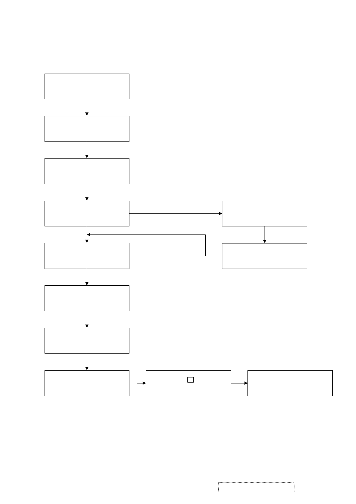
6. Troubleshooting Flow Chart
6.1 No power.
Check that CN251 pin1, are approximately 24V
Yes
Check that C281 are 24V
Yes
Check that C262 positive is at 5V.
No
Failure point
1. Adaptor failure.
2. Disconnected between CN251 and Adaptor.
No
Failure point
FB251, FB251 failure
No
Failure point
D251, IC251, L251, Q255 failure
Yes
Check:
1. IC255 is O/P 3.3V.
2. IC253 is O/P 1.8V.
3. IC256 is O/P 2.5V.
4. IC252 is O/P 3.3V.
No
IC255, IC253, IC252, IC256
Failure point
ViewSonic Corporation Confidential
37
-
Do Not Copy VP201b/s-1
Page 41

6.2 No display on screen (Screen is black, LED is off).
AC power on and DC power on
Yes
Yes
No
Follow item 6.1
Yes
Check that C265 positive is at 18V LED is light or not?
Yes
Q258, D252, L263, L254Check C276 pin8 is 18V
No
Q251, Q262 failureInverter failure
No
ViewSonic Corporation Confidential
38
-
Do Not Copy VP201b/s-1
Page 42

6.3 Show “No signal” on screen.
Check that signal level of D-sub, DVI-A or DVI-D
Yes
Check the R.G.B and H/V
Sync in IC606, IC607
IC606, IC607 Failure
6.4 Keypad cannot work.
No
Failure point
Yes
1. IC401 failure.
2. Signal cable is disconnected.
Yes
Failure point
Q401. Q402. Q403, Q404 failure
Check the the cable is fully conneted between the interface
board and key board
No
Failure point
The keypad is disconnected.
ViewSonic Corporation Confidential
29
-
Do Not Copy VP201b/s-1
Page 43

C-00001883
7. Recommended Spare Parts List
ViewSonic Model Number: VLCDS26064-2W
Rev: 1e
Item ECR/ECN ViewSonic P/N Ref. P/N Location Universal number# Q'ty
Accessories:
1
2
PC Board Assembly:
3
4
5
Cabinets:
6
7
8
9
Cables:
10
11
12
13
14
15 WIRE WITH HOUSING 1571 #28 L155 30P Added 05/09/05 CB-00002544 3679046000 1
16 CARD ATTENTION SHEET 190*125 VSC-20/21 Added 05/09/05 DC-00001459 5012046900 1
Documentation:
17
18
19
20
21
22
23
24
25
26
Electronic
27
Components:
28
Hardware:
29
30
31
32
33
34
35
36
37
38
39
40
41
42
Miscellaneous:
43
44
45
46
47
48
49
50
51
52
53
54
55
56
57
58
Packing Material:
59
60
61
62
63
64
65
66
67
68
69
70
71
72
AC POWER CORD L=1800 BLK NA #18*3C SVT C A-PC-0106-0150 3090107601 1
POWER SUPPLY 60W 18V 3.33A A-00001842 4900210180 1
DC-AC INVERTER FOR L20DBR B-00001843 4900506980 1
PWB ASSY I/F BD L20DBR 05FAB
PWB ASSY I/F BD L20DBR 05DAB B-00002542 5600110420 1
SWITCH MEMBRANCE PET 99.5*9 VP181-2 M-SW-0815-0224 3000725101 1
CABINET ASSY L20DBW05ABB S0LRA1AT C-00001884 3368224100 1
COVER VESA ABS MIDNIGHT GRAY-2 S8LRB1LS M-CV-0830-2442 3362010801 1
F/B ASSY L20CBW05ABB S0LFA1AT
F/B ASSY L20DBW05DBB S0LFA1AT C-00002551 3368321000 1
STAND ASSY L20CBW05ABB S8LBB1LS C-00001885 3368990304 1
CABLE D-SUB/D-SUB L1800 BLK OD7.5 A-VC-0101-0390 3080427000 1
CABLE DVI-D TO DVI-D L1800 P001 A-VC-0101-0370 3080428100 1
CABLE FFC 30P P1.0 L340 T1 LG M-FC-0809-0838 3080516301 1
CABLE USB 2.0 A_B L1800 BLACK M-MS-0808-8555 3080323801 1
WIRE WITH HOUSING 1007 #26 L25 6P CB-00001886 3670627400 1
CD-ROM VSC A-CD-VP201B-1 L20DBW DC-00001887 3532091300 1
LABEL BAR CODE 124*82 M-LB-0813-0978 3200787200 1
LABEL HV WARNING 100*25 M-LB-0813-0714 3202310700 1
LABEL ID 100*50 VSC VP201B L20DBW DC-00001889 3201985200 1
LABEL STICKER OD10 WHT HI-POT M-LB-0813-0785 3200158900 1
LABEL USB 35*20 VSC VP SERIES DC-00000639 3209216600 1
LABEL WARNING 81.7*81.7 VSC DC-00000424 3202334500 1
MANUAL PACKING ASSY VSC VP201B L20DBW DC-00001888 3532091400 1
NAME PLATE VSC 3-BIRD LOGO AL 11.07*7.92 M-MS-0808-8556 3200649100 1
PORTRAIT CD VSC A-CD-0002 V7.5 TAIWAN A-CD-VP181S-2 3532065001 1
CORE BEAD 40*6.5*10 W5H+TAPE E-L-0407-1587 2921021404 1
LCD 20.1" TFT PANEL UXGA
LCD 20.1" TFT LVDS UXGA E-00002545 5052000402 1
BRACKET PANEL ASSY L20DBR05AAB
PANEL BKT ASSY L20DBR 05DAB HW-00002547 3790188200 1
BRACKET PANEL SIDE-L SECC 325*30*25 T.8 M-MS-0808-8631 3460150200 1
BRACKET PANEL SIDE-R SECC 325*30*25 T.8 M-MS-0808-8630 3460150100 1
SCREW M #4-40*7 HEXH #4-40*3 S18C NI M-SCW-0824-0690 3105051501 4
SCREW M M3*0.5*4 FF C S18C ZN M-SCW-0824-0777 3105225300 6
SCREW M M3*0.5*6 FF C S18C ZN M-SCW-0824-0776 3105221000 6
SCREW M M3*0.5*8 FPH C S20C ZN BLK
SCREW M M3*0.5*5 PAN C S18C ZN BLK HW-00002546 3100430500 4
SCREW M M4*0.7*10 FF C S18C ZN BLK NYLOK M-SCW-0824-0775 3105123700 4
SCREW T M3*0.5*4 BIND C S18C ZN YEL M-SCW-0824-0732 3109010900 4
SCREW T M3*0.5*6 BIND C S18C ZN YEL M-SCW-0824-0413 3109011400 4
SCREW T M3*0.5*7 PAN C S+P S20C ZN M-SCW-0824-0784 3109010700 1
SHIELD CAN INV SPTH 208.5*73.8*18 T.3 HW-00001848 3461226501 1
SHIELD CAN SPTH 289.9*150.1*41.5 T.3 HW-00001849 3461256200 1
WASHER SPRING SWRT M-MS-0808-8040 3110250000 4
CONDUCTIVE SPONGE 10*10*12 M-MS-0808-8646 3472855100 1
CONDUCTIVE SPONGE 30*8.5*10 M-MS-0808-8643 3472851200 1
CONDUCTIVE TAPE AL W50*L55 1120 M-MS-0808-8557 3240055600 1
INSULATOR PC 130*118.5 T.5
INSULATOR PC 130*118.5 T.43 BLK M-00002548 3241194300 1
INSULATOR PC 231*13 T.5 M-MS-0808-8627 3241127400 1
SPONGE EVA 5.8*5 T.5 BLK M-MS-0808-2276 3240160801 1
TAPE AL FOIL W=25 #80023 CATERON M-MS-0808-1679 3222201300 0.465
TAPE AL FOIL W=50 TAPE AL-35FR 3M M-00001850 3222201510 0.11
TAPE PE W=50 VIEWSONIC SECURITY M-MS-0808-0918 3221903300 1.028
TAPE W=10 #1350F-1 3M M-MS-0808-8202 3220133600 0.04
TAPE W=16 #897 3M M-MS-0808-1680 3222400310 0.03
TAPE W=20 #1350F-1 3M M-00001851 3220130800 0.062
TAPE W=20 #3800A NITTO M-MS-0808-0724 3220161733 0.15
TAPE W=30 #10 3M M-MS-0808-7463 3220501600 0.29
TAPE W=45 #7290 NITTO M-MS-0808-7810 3220605633 0.128
TAPE W=76 PP47 914M 4P M-MS-0808-4975 3221101500 0.8
ANGLE PAPER 2070*55*55 T5 M-MS-0808-2815 3511208300 0.375
CAP PAPER 1130*1390*120 M-MS-0808-3190 3510449200 0.032
CAP PAPER 1130*700*120 M-MS-0808-2672 3510449300 0.063
CARTON 552*337*489 VSC VP201B (DET)
CARTON 552*337*489 VSC VP201B 3512238902
DRYER 15G 80*60 M-MS-0808-7820 3520130500 2
END BLOCK-BOTTOM EPS L20CBW05AAW P-FM-0602-0592 3500105600 1
END BLOCK-TOP EPS L20CBW05AAW P-FM-0602-0591 3500105500 1
PALLET FUMIGATE 1120*690*120 P-00001892 3524009501 0.063
PALLET FUMIGATE 1380*1120*120 P-00001891 3524009401 0.032
PE BAG 300*200*0.06T M-MS-0808-8762 3500937501 1
PE BAG 740*580*.06T CLEAR M-MS-0808-2667 3500939901 1
PE BAG 75*75*160L T.1 M-MS-0808-2671 3500943900 2
PE FILM t=0.02mm W=500 M-MS-0808-5135 3520082400 0.04
PLASTIC STRIP W=12 T.5 BLACK PL-SP-0723-0002 3520142700 1
RECOMMENDED SPARE PARTS LIST (VP201b-1 for "AUO Panel")
Description
Removed and Replaced
Part 05/09/05
Removed and Replaced
Part 05/09/05
Removed and Replaced
Part 05/09/05
Removed and Replaced
Part 05/09/05
Removed and Replaced
Part 05/09/05
Removed and Replaced
Part 05/09/05
Update Vendor P/N
05/09/05
B-00001882 5600110394 1
M-LCD-0826-0205 5052000450 1
HW-00001890 3790196001 1
M-SCW-0824-0772 3100130800 4
M-MS-0808-0016 3241127301 1
P-BX-0601-0813
3368192604 1
3512238901
1
ViewSonic Corporation Confidential
40
-
Do Not Copy VP201b/s-1
Page 44

Item ECR/ECN ViewSonic P/N Ref. P/N Location Universal number# Q'tyDescription
Plastics:
73
74
75
76
77
78
79
HANDLE PE 162*40.5 T1.5 BOTTOM NO501 M-MS-0808-2660 3470903500 1
HANDLE PE 209*18 T1.8 TOP NO501 M-MS-0808-2662 3470903600 1
POWER KNOB POM M270 MIDNIGHT GRAY S8LRB1 PL-NB-0707-0192 3360624900 1
RUBBER PAD 25*10*1.5 BLACK STICK M-MS-0808-5271 3240498900 1
RUBBER PAD 22*4 T3 BLK PL-PD-0714-0140 3240970900 1
RUBBER PAD 25*25*2 PL-PD-0714-0066 3240954400 1
RUBBER SILICON 12*12 T5 M-MS-0808-2631 3240946900 2
ViewSonic Corporation Confidential
41
-
Do Not Copy VP201b/s-1
Page 45

RECOMMENDED SPARE PARTS LIST (VP201s-1 for "AUO V.3 Panel")
ViewSonic Model Number: VLCDS26064-4W
Rev: 1d
Item ECR/ECN ViewSonic P/N Ref. P/N Location Universal number# Q'ty
Accessories:
1
PC Board Assembly:
2
3
4
5
Cabinets:
6
7
8
9
Cables:
10
11
12
13
14
15 WIRE WITH HOUSING 1571 #28 L155 30P Added 05/09/05 CB-00002544 3679046000 1
16 CARD ATTENTION SHEET 190*125 VSC-20/21 Added 05/09/05 DC-00001459 5012046900 1
Documentation:
17
18
19
20
21
22
23
24
25
Electronic
26
Components:
27
Hardware:
28
29
30
31
32
33
34
35
36
37
38
39
40
41
42 PANEL BKT ASSY L20DBR 05DAB Added 05/09/05 HW-00002547 3790188200 1
Miscellaneous:
43
44
45
46
47
48
49
50
51
52
53
54
55
56
57
58
59
60
Packing Material:
61
62
63
65
66
67
68
69
70
71
72
73
74
Description
AC POWER CORD L=1800 BLK NA #18*3C SVT C A-PC-0106-0150 3090107601 1
DC-AC INVERTER FOR L20DBR B-00001843 4900506980 1
POWER SUPPLY 60W 18V 3.33A A-00001842 4900210180 1
PWB ASSY I/F BD L20DBR 05FAB
PWB ASSY I/F BD L20DBR 05DAB B-00002542 5600110420 1
SWITCH MEMBRANCE PET 99.5*9 VP181-2 M-SW-0815-0224 3000725101 1
CABINET ASSY L20DBR05AAB S0LRA1AT C-00001895 3368223600 1
COVER VESA ABS 41S8LBB1LS M-CV-0830-2458 3361207400 1
F/B ASSY L20CBR05ADB S0LFA1AT
F/B ASSY L20DBR05DAB S0LFA1AT C-00002543 3368321100 1
STAND ASSY L20CBR05ADB S8LBB1LS C-BS-0303-0554 3368991403 1
CABLE D-SUB/D-SUB L1800 BLK OD7.5 A-VC-0101-0390 3080427000 1
CABLE DVI-D TO DVI-D L1800 P001 A-VC-0101-0370 3080428100 1
CABLE FFC 30P P1.0 L340 T1 LG
CABLE USB 2.0 A_B L1800 BLACK M-MS-0808-8555 3080323801 1
WIRE WITH HOUSING 1007 #26 L25 6P CB-00001886 3670627400 1
CD-ROM VSC A-CD-VP201S-1 L20DBR DC-00001896 3532091100 1
LABEL BAR CODE 124*82 M-LB-0813-0978 3200787200 1
LABEL HV WARNING 100*25 M-LB-0813-0714 3202310700 1
LABEL ID 100*50 VSC VP201S L20DBR DC-00001897 3201985100 1
LABEL STICKER OD10 WHT HI-POT M-LB-0813-0785 3200158900 1
LABEL USB 35*20 VSC VP SERIES DC-00000639 3209216600 1
LABEL WARNING 81.7*81.7 VSC DC-00000424 3202334500 1
MANUAL PACKING ASSY VSC VP201S L20DBR DC-00001898 3532091200 1
PORTRAIT CD VSC A-CD-0002 V7.5 TAIWAN A-CD-VP181S-2 3532065001 1
CORE BEAD 40*6.5*10 W5H+TAPE E-L-0407-1587 2921021404 1
LCD 20.1" TFT PANEL UXGA
LCD 20.1" TFT LVDS UXGA E-00002545 5052000402 1
BRACKET PANEL ASSY L20DBR05AAB HW-00001890 3790196001 1
BRACKET PANEL SIDE-L SECC 325*30*25 T.8 M-MS-0808-8631 3460150200 1
BRACKET PANEL SIDE-R SECC 325*30*25 T.8 M-MS-0808-8630 3460150100 1
SCREW M #4-40*7 HEXH #4-40*3 S18C NI M-SCW-0824-0690 3105051501 4
SCREW M M3*0.5*4 FF C S18C ZN M-SCW-0824-0777 3105225300 6
SCREW M M3*0.5*6 FF C S18C ZN M-SCW-0824-0776 3105221000 6
SCREW M M3*0.5*8 FPH C S20C ZN BLK
SCREW M M3*0.5*5 PAN C S18C ZN BLK HW-00002546 3100430500 4
SCREW M M4*0.7*10 FF C S18C ZN BLK NYLOK M-SCW-0824-0775 3105123700 4
SCREW T M3*0.5*4 BIND C S18C ZN YEL M-SCW-0824-0732 3109010900 4
SCREW T M3*0.5*6 BIND C S18C ZN YEL M-SCW-0824-0413 3109011400 4
SCREW T M3*0.5*7 PAN C S+P S20C ZN M-SCW-0824-0784 3109010700 1
SHIELD CAN INV SPTH 208.5*73.8*18 T.3 HW-00001848 3461226501 1
SHIELD CAN SPTH 289.9*150.1*41.5 T.3 HW-00001849 3461256200 1
WASHER SPRING SWRT M-MS-0808-8040 3110250000 4
CONDUCTIVE AL 15*25 T0.06 M-MS-0808-8640 3463000700 1
CONDUCTIVE SPONGE 10*10*12 M-MS-0808-8646 3472855100 1
CONDUCTIVE SPONGE 30*8.5*10 M-MS-0808-8643 3472851200 1
CONDUCTIVE TAPE AL W50*L55 1120 M-MS-0808-8557 3240055600 1
INSULATOR PC 130*118.5 T.5
INSULATOR PC 130*118.5 T.43 BLK M-00002548 3241194300 1
INSULATOR PC 231*13 T.5 M-MS-0808-8627 3241127400 1
SPONGE EVA 5.8*5 T.5 BLK M-MS-0808-2276 3240160801 1
TAPE AL FOIL W=25 #80023 CATERON M-MS-0808-1679 3222201300 0.465
TAPE AL FOIL W=50 TAPE AL-35FR 3M M-00001850 3222201510 0.11
TAPE PE W=50 VIEWSONIC SECURITY M-MS-0808-0918 3221903300 1.028
TAPE W=10 #1350F-1 3M M-MS-0808-8202 3220133600 0.04
TAPE W=16 #897 3M M-MS-0808-1680 3222400310 0.03
TAPE W=20 #1350F-1 3M M-00001851 3220130800 0.062
TAPE W=20 #3800A NITTO M-MS-0808-0724 3220161733 0.15
TAPE W=28 CM34 4P
TAPE W=30 #10 3M M-MS-0808-7463 3220501600 0.29
TAPE W=45 #7290 NITTO M-MS-0808-7810 3220605633 0.128
TAPE W=76 PP47 914M 4P M-MS-0808-4975 3221101500 0.8
ANGLE PAPER 2070*55*55 T5 M-MS-0808-2815 3511208300 0.375
CAP PAPER 1130*1390*120 M-MS-0808-3190 3510449200 0.032
CAP PAPER 1130*700*120 M-MS-0808-2672 3510449300 0.063
DRYER 15G 80*60 M-MS-0808-7820 3520130500 2
END BLOCK-BOTTOM EPS L20CBW05AAW P-FM-0602-0592 3500105600 1
END BLOCK-TOP EPS L20CBW05AAW P-FM-0602-0591 3500105500 1
PALLET FUMIGATE 1120*690*120 P-00001892 3524009501 0.063
PALLET FUMIGATE 1380*1120*120 P-00001891 3524009401 0.032
PE BAG 300*200*0.06T M-MS-0808-8762 3500937501 1
PE BAG 740*580*.06T CLEAR M-MS-0808-2667 3500939901 1
PE BAG 75*75*160L T.1 M-MS-0808-2671 3500943900 2
PE FILM t=0.02mm W=500 M-MS-0808-5135 3520082400 0.04
PLASTIC STRIP W=12 T.5 BLACK PL-SP-0723-0002 3520142700 1
Removed and Replaced
Part 05/09/05
Removed and Replaced
Part 05/09/05
Removed 05/09/05
Removed and Replaced
Part 05/09/05
Removed and Replaced
Part 05/09/05
Removed and Replaced
Part 05/09/05
Removed 05/09/05 M-00001899 3220601000 0.1
Update Vendor P/N64P-BX-0601-0877CARTON 552*337*489 VSC VP201S 1
B-00001882 5600110394 1
C-00001893 3368197901 1
M-FC-0809-0838 3080516301 1
M-LCD-0826-0205 5052000450 1
M-SCW-0824-0772 3100130800 4
M-MS-0808-0016 3241127301 1
3512244600
3512244601
ViewSonic Corporation Confidential
42
-
Do Not Copy VP201b/s-1
Page 46

Item ECR/ECN ViewSonic P/N Ref. P/N Location Universal number# Q'tyDescription
75
76
77
78
79
80
81
Plastics:
HANDLE PE 162*40.5 T1.5 BOTTOM NO501 M-MS-0808-2660 3470903500 1
HANDLE PE 209*18 T1.8 TOP NO501 M-MS-0808-2662 3470903600 1
NAME PLATE VSC 3-BIRD LOGO AL 11.07*7.92 M-MS-0808-8556 3200649100 1
POWER KNOB POM 901U 5140 S8LFB1LS PL-NB-0707-1075 3360627100 1
RUBBER PAD 22*4 T3 BLK PL-PD-0714-0140 3240970900 1
RUBBER PAD 25*25*2 PL-PD-0714-0066 3240954400 1
RUBBER SILICON 12*12 T5 M-MS-0808-2631 3240946900 2
ViewSonic Corporation Confidential
43
-
Do Not Copy VP201b/s-1
Page 47

BOM LIST (VP201b-1 for "AUO Panel")
ViewSonic Model Number: VLCDS26064-2W
Rev: 1c
Item ViewSonic P/N Ref. P/N Description Location Q'ty Unit
1 E-L-0407-1587 2921021404 CORE BEAD 40*6.5*10 W5H+TAPE 1 PCE
2 E-L-0407-1587 2921021437 CORE BEAD 40*6.5*10 A5 +TAPE 0 PCE
3 M-SW-0815-0224 3000725101 SWITCH MEMBRANCE PET 99.5*9 VP181-2 1 PCE
4 M-MS-0808-8555 3080323801 CABLE USB 2.0 A_B L1800 BLACK 1 PCE
5 A-VC-0101-0390 3080427000 CABLE D-SUB/D-SUB L1800 BLK OD7.5 1 PCE
6 A-VC-0101-0370 3080428100 CABLE DVI-D TO DVI-D L1800 P001 1 PCE
7 A-PC-0106-0150 3090107601 AC POWER CORD L=1800 BLK NA #18*3C SVT C 1 PCE
8 HW-00002546 3100430500 SCREW M M3*0.5*5 PAN C S18C ZN BLK 4 PCE
9 M-SCW-0824-0690 3105051501 SCREW M #4-40*7 HEXH #4-40*3 S18C NI 4 PCE
10 M-SCW-0824-0775 3105123700 SCREW M M4*0.7*10 FF C S18C ZN BLK NYLOK 4 PCE
11 M-SCW-0824-0776 3105221000 SCREW M M3*0.5*6 FF C S18C ZN 6 PCE
12 M-SCW-0824-0777 3105225300 SCREW M M3*0.5*4 FF C S18C ZN 6 PCE
13 M-SCW-0824-0784 3109010700 SCREW T M3*0.5*7 PAN C S+P S20C ZN 1 PCE
14 M-SCW-0824-0732 3109010900 SCREW T M3*0.5*4 BIND C S18C ZN YEL 4 PCE
15 M-SCW-0824-0413 3109011400 SCREW T M3*0.5*6 BIND C S18C ZN YEL 4 PCE
16 M-MS-0808-8040 3110250000 WASHER SPRING SWRT 4 PCE
17 M-LB-0813-0785 3200158900 LABEL STICKER OD10 WHT HI-POT 1 PCE
18 M-LB-0813-0712 3200449700 LABEL WARING 0 PCE
19 M-MS-0808-8556 3200649100 NAME PLATE VSC 3-BIRD LOGO AL 11.07*7.92 1 PCE
20 M-LB-0813-0978 3200787200 LABEL BAR CODE 124*82 1 PCE
21 DC-00001889 3201985200 LABEL ID 100*50 VSC VP201B L20DBW 1 PCE
22 M-LB-0813-0714 3202310700 LABEL HV WARNING 100*25 1 PCE
23 DC-00000424 3202334500 LABEL WARNING 81.7*81.7 VSC 1 PCE
24 DC-00000639 3209216600 LABEL USB 35*20 VSC VP SERIES 1 PCE
25 M-MS-0808-8624 3211030700 MYLAR FILM 430*330 T.1 L20CBR05ACA 0 PCE
26 #N/A 3220130500 TAPE W=17 #1350F-1 3M 0.05 MTR
27 M-00001851 3220130800 TAPE W=20 #1350F-1 3M 0.062 MTR
28 M-MS-0808-7011 3220131000 TAPE W=23 #1350F-1 3M 0.05 MTR
29 M-MS-0808-8202 3220133600 TAPE W=10 #1350F-1 3M 0.04 MTR
30 M-MS-0808-0724 3220161733 TAPE W=20 #3800A NITTO 0.15 MTR
31 M-MS-0808-7463 3220501600 TAPE W=30 #10 3M 0.29 MTR
32 M-MS-0808-7810 3220605633 TAPE W=45 #7290 NITTO 0.128 MTR
33 M-MS-0808-4975 3221101500 TAPE W=76 PP47 914M 4P 0.8 MTR
34 M-MS-0808-0918 3221903300 TAPE PE W=50 VIEWSONIC SECURITY 1.028 MTR
35 M-MS-0808-1679 3222201300 TAPE AL FOIL W=25 #80023 CATERON 0.465 MTR
36 M-00001850 3222201510 TAPE AL FOIL W=50 TAPE AL-35FR 3M 0.11 MTR
37 M-MS-0808-1680 3222400310 TAPE W=16 #897 3M 0.03 MTR
38 M-MS-0808-8557 3240055600 CONDUCTIVE TAPE AL W50*L55 1120 1 PCE
39 M-MS-0808-2276 3240160801 SPONGE EVA 5.8*5 T.5 BLK 1 PCE
40 M-MS-0808-5271 3240498900 RUBBER PAD 25*10*1.5 BLACK STICK 1 PCE
41 M-MS-0808-2631 3240946900 RUBBER SILICON 12*12 T5 2 PCE
42 PL-PD-0714-0066 3240954400 RUBBER PAD 25*25*2 1 PCE
43 PL-PD-0714-0140 3240970900 RUBBER PAD 22*4 T3 BLK 1 PCE
44 M-MS-0808-8627 3241127400 INSULATOR PC 231*13 T.5 1 PCE
45 M-00002548 3241194300 INSULATOR PC 130*118.5 T.43 BLK 1 PCE
46 PL-NB-0707-0192 3360624900 POWER KNOB POM M270 MIDNIGHT GRAY S8LRB1 1 PCE
47 M-CV-0830-2446 3362010801 COVER VESA ABS MIDNIGHT GRAY-2 S8LRB1LS 1 PCE
48 #N/A 4020374207 PLASTIC ABS 94HB MIDNIGHT GRAY-2 D-180 64 GRM
49 #N/A 4020374208 PLASTIC ABS 94HB MIDNIGHT GRAY-2 HF-380 0 GRM
50 #N/A 4020374209 PLASTIC ABS 94HB MIDNIGHT GRAY-2 SD-0150 0 GRM
51 #N/A 4020374214 PLASTIC ABS 94HB MIDNIGHT GRAY-2 PA-707 0 GRM
52 C-00001884 3368224100 CABINET ASSY L20DBW05ABB S0LRA1AT 1 PCE
53 M-MS-0808-8622 3200649200 NAME PLATE VIEWSONIC ABS 82.83*34.98 1 PCE
54 #N/A 4020374207 PLASTIC ABS 94HB MIDNIGHT GRAY-2 D-180 4 GRM
55 #N/A 4020374208 PLASTIC ABS 94HB MIDNIGHT GRAY-2 HF-380 0 GRM
56 #N/A 4020374209 PLASTIC ABS 94HB MIDNIGHT GRAY-2 SD-0150 0 GRM
57 #N/A 4020374214 PLASTIC ABS 94HB MIDNIGHT GRAY-2 PA-707 0 GRM
58 #N/A 3360257200 CABINET BACK ABS MIDNIGHT GRAY-2 S0LRA1A 1 PCE
59 #N/A 4020374207 PLASTIC ABS 94HB MIDNIGHT GRAY-2 D-180 520 GRM
60 #N/A 4020374208 PLASTIC ABS 94HB MIDNIGHT GRAY-2 HF-380 0 GRM
61 #N/A 4020374209 PLASTIC ABS 94HB MIDNIGHT GRAY-2 SD-0150 0 GRM
62 #N/A 4020374214 PLASTIC ABS 94HB MIDNIGHT GRAY-2 PA-707 0 GRM
63 M-MS-0808-8561 3460146100 BRACKET VESA SECC 110*20 T1 1 PCE
64 M-MS-0808-8563 3460146300 BRACKET KEYLOCK SECC 20.4*16.45*4.9 T.6 1 PCE
65 C-00002551 3368321000 F/B ASSY L20DBW05DBB S0LFA1AT 1 PCE
66 M-MS-0808-8559 3360506800 LED LENS ABS 1865-12 S8LRB1LS 1 PCE
67 #N/A 4020370614 PLASTIC ABS 94HB 1865-12 PA-758 0.1 GRM
68 #N/A 3361502000 F/B ABS MIDNIGHT GRAY-2 VP201B S0LFA1AT 1 PCE
69 #N/A 4020372907 PLASTIC ABS 94HB 5140 D-180 160 GRM
70 #N/A 4020372908 PLASTIC ABS 94HB 5140 HF-380 0 GRM
71 #N/A 4020372909 PLASTIC ABS 94HB 5140 SD-0150 0 GRM
72 #N/A 4020372914 PLASTIC ABS 94HB 5140 PA-757 0 GRM
73 C-00001885 3368990304 STAND ASSY L20CBW05ABB S8LBB1LS 1 PCE
74 M-SCW-0824-0781 3105127100 SCREW M M4*0.7*12 FF C S18C ZN NL 4 PCE
75 M-SCW-0824-0778 3105229400 SCREW M M3*0.5*10 FF C S18C ZN 1 PCE
76 M-SCW-0824-0782 3105280200 SCREW M M3*0.5*4 FF C S18C ZN BLK 2 PCE
77 M-SCW-0824-0779 3109017700 SCREW T M3*2.7*7.5 FF C S18C ZN YEL 2 PCE
ViewSonic Corporation Confidential
44
-
Do Not Copy VP201b/s-1
Page 48

Item ViewSonic P/N Ref. P/N Description Location Q'ty Unit
78 M-SCW-0824-0780 3109019100 SCREW T M3*2.7*7.2 FLAT C S18C ZN YEL 4 PCE
79 M-CV-0830-2443 3361204901 COVER STAND FRONT ABS MIDNIGHT GRAY-2 S8 1 PCE
80 #N/A 4020374207 PLASTIC ABS 94HB MIDNIGHT GRAY-2 D-180 49 GRM
81 #N/A 4020374208 PLASTIC ABS 94HB MIDNIGHT GRAY-2 HF-380 0 GRM
82 #N/A 4020374209 PLASTIC ABS 94HB MIDNIGHT GRAY-2 SD-0150 0 GRM
83 #N/A 4020374214 PLASTIC ABS 94HB MIDNIGHT GRAY-2 PA-707 0 GRM
84 M-CV-0830-2444 3361205101 COVER STAND REAR ABS MIDNIGHT GRAY-2 S8L 1 PCE
85 #N/A 4020374207 PLASTIC ABS 94HB MIDNIGHT GRAY-2 D-180 37 GRM
86 #N/A 4020374208 PLASTIC ABS 94HB MIDNIGHT GRAY-2 HF-380 0 GRM
87 #N/A 4020374209 PLASTIC ABS 94HB MIDNIGHT GRAY-2 SD-0150 0 GRM
88 #N/A 4020374214 PLASTIC ABS 94HB MIDNIGHT GRAY-2 PA-707 0 GRM
89 M-CV-0830-2439 3361205201 COVER BASE ABS MIDNIGHT GRAY-2 S8LBB1LS 1 PCE
90 #N/A 4020374207 PLASTIC ABS 94HB MIDNIGHT GRAY-2 D-180 20 GRM
91 #N/A 4020374208 PLASTIC ABS 94HB MIDNIGHT GRAY-2 HF-380 0 GRM
92 #N/A 4020374209 PLASTIC ABS 94HB MIDNIGHT GRAY-2 SD-0150 0 GRM
93 #N/A 4020374214 PLASTIC ABS 94HB MIDNIGHT GRAY-2 PA-707 0 GRM
94 M-CV-0830-2440 3361205300 COVER HINGE1 ABS MIDNIGHT GRAY S8LBB1LS 1 PCE
95 #N/A 4020374207 PLASTIC ABS 94HB MIDNIGHT GRAY-2 D-180 30 GRM
96 #N/A 4020374208 PLASTIC ABS 94HB MIDNIGHT GRAY-2 HF-380 0 GRM
97 #N/A 4020374209 PLASTIC ABS 94HB MIDNIGHT GRAY-2 SD-0150 0 GRM
98 #N/A 4020374214 PLASTIC ABS 94HB MIDNIGHT GRAY-2 PA-707 0 GRM
99 M-CV-0830-2441 3361205402 COVER HINGE ABS MIDNIGHT GRAY-2 S8LRB1LS 1 PCE
100 #N/A 4020374207 PLASTIC ABS 94HB MIDNIGHT GRAY-2 D-180 7.5 GRM
101 #N/A 4020374208 PLASTIC ABS 94HB MIDNIGHT GRAY-2 HF-380 0 GRM
102 #N/A 4020374209 PLASTIC ABS 94HB MIDNIGHT GRAY-2 SD-0150 0 GRM
103 #N/A 4020374214 PLASTIC ABS 94HB MIDNIGHT GRAY-2 PA-707 0 GRM
104 #N/A 3368230302 BASE BOTTOM ASSY L20CBW05ABB S0LBB1AT 1 PCE
105 M-SCW-0824-0773 3105034400 SCREW M M3*0.5*6 FLAT C S20C ZN NL(P) 6 PCE
106 M-SCW-0824-0779 3109017700 SCREW T M3*2.7*7.5 FF C S18C ZN YEL 2 PCE
107 M-SCW-0824-0780 3109019100 SCREW T M3*2.7*7.2 FLAT C S18C ZN YEL 2 PCE
108 M-CV-0830-2445 3361207000 COVER STAND BOTTOM ABS MIDNIGHT GRAY S0L 1 PCE
109 #N/A 4020374207 PLASTIC ABS 94HB MIDNIGHT GRAY-2 D-180 209 GRM
110 #N/A 4020374208 PLASTIC ABS 94HB MIDNIGHT GRAY-2 HF-380 0 GRM
111 #N/A 4020374209 PLASTIC ABS 94HB MIDNIGHT GRAY-2 SD-0150 0 GRM
112 #N/A 4020374214 PLASTIC ABS 94HB MIDNIGHT GRAY-2 PA-707 0 GRM
113 #N/A 3790184301 BKT BASE ASSY L20CBR05ACB 1 PCE
114 M-SCW-0824-0773 3105034400 SCREW M M3*0.5*6 FLAT C S20C ZN NL(P) 2 PCE
115 PL-PD-0714-0100 3240957000 RUBBER PAD OD20 T4 BLACK 2 PCE
116 PL-PD-0714-0101 3240968900 RUBBER PAD 20*20 T3 BLK 1 PCE
117 M-MS-0808-8632 3460150703 BRACKET BASE2 SECC 173*190.4 T2 VP201 1 PCE
118 M-MS-0808-8635 3460151002 BRACKET BASE3 SECC 173*190.4 T2 VP201 1 PCE
119 M-MS-0808-8636 3460151102 BRACKET BASE1 SECC 173*190.4 T2 VP201 1 PCE
120 #N/A 3790184400 BKT BASE FOOT ASSY L20CBR05ACB 2 PCE
121 M-SCW-0824-0783 3105280400 SCREW M M3*0.5*4 FLAT C S20C ZN NL 2 PCE
122 PL-PD-0714-0100 3240957000 RUBBER PAD OD20 T4 BLACK 1 PCE
123 M-MS-0808-8633 3460150801 BRACKET BASE FOOT1 SECC 195.3*62.5 T2 VP 1 PCE
124 M-MS-0808-8634 3460150902 BRACKET BASE FOOT2 SECC 195.3*62.5 T2 VP 1 PCE
125 M-MS-0808-8639 3461752201 HINGE SECC 312.5*51.82 L20CBW05ABB 1 PCE
126 M-MS-0808-8573 3470307501 WIRE SADDLE NYLON66 94V2 MIDNIGHT GRAY 3 PCE
127 M-MS-0808-8630 3460150100 BRACKET PANEL SIDE-R SECC 325*30*25 T.8 1 PCE
128 M-MS-0808-8631 3460150200 BRACKET PANEL SIDE-L SECC 325*30*25 T.8 1 PCE
129 HW-00001848 3461226501 SHIELD CAN INV SPTH 208.5*73.8*18 T.3 1 PCE
130 HW-00001849 3461256200 SHIELD CAN SPTH 289.9*150.1*41.5 T.3 1 PCE
131 M-MS-0808-2660 3470903500 HANDLE PE 162*40.5 T1.5 BOTTOM NO501 1 PCE
132 M-MS-0808-2662 3470903600 HANDLE PE 209*18 T1.8 TOP NO501 1 PCE
133 M-MS-0808-8643 3472851200 CONDUCTIVE SPONGE 30*8.5*10 1 PCE
134 M-MS-0808-8646 3472855100 CONDUCTIVE SPONGE 10*10*12 1 PCE
135 P-FM-0602-0591 3500105500 END BLOCK-TOP EPS L20CBW05AAW 1 PCE
136 P-FM-0602-0591 3500105600 END BLOCK-BOTTOM EPS L20CBW05AAW 1 PCE
137 M-MS-0808-8762 3500937501 PE BAG 300*200*0.06T 1 PCE
138 M-MS-0808-2667 3500939901 PE BAG 740*580*.06T CLEAR 1 PCE
139 M-MS-0808-2671 3500943900 PE BAG 75*75*160L T.1 2 PCE
140 M-MS-0808-3190 3510449200 CAP PAPER 1130*1390*120 0.032 PCE
141 M-MS-0808-2672 3510449300 CAP PAPER 1130*700*120 0.063 PCE
142 M-MS-0808-2815 3511208300 ANGLE PAPER 2070*55*55 T5 0.375 PCE
143 P-BX-0601-0813 3512238902 CARTON 552*337*489 VSC VP201B 1 PCE
144 M-MS-0808-5135 3520082400 PE FILM t=0.02mm W=500 0.04 KGM
145 M-MS-0808-7820 3520130500 DRYER 15G 80*60 2 PCE
146 PL-SP-0723-0002 3520142700 PLASTIC STRIP W=12 T.5 BLACK 1 MTR
147 P-00001891 3524009401 PALLET FUMIGATE 1380*1120*120 0.032 PCE
148 P-00001892 3524009501 PALLET FUMIGATE 1120*690*120 0.063 PCE
149 M-MS-0808-3275 3524009601 PALLET FUMIGATE 1120*1380*120 0 PCE
150 M-MS-0808-3374 3524009701 PALLET FUMIGATE 1120*690*120 0 PCE
151 A-CD-VP181S-2 3532065001 PORTRAIT CD VSC A-CD-0002 V7.5 TAIWAN 1 PCE
152 DC-00001887 3532091300 CD-ROM VSC A-CD-VP201B-1 L20DBW 1 PCE
153 DC-00001888 3532091400 MANUAL PACKING ASSY VSC VP201B L20DBW 1 PCE
154 M-MS-0808-8396 3520094201 PE BAG 260*155*0.1T 1 PCE
155 #N/A 5010009200 MANUAL QSG VP201B L20DBW 1 PCE
156 CB-00001886 3670627400 WIRE WITH HOUSING 1007 #26 L25 6P 1 PCE
157 CB-00002544 3679046000 WIRE WITH HOUSING 1571 #28 L155 30P 1 PCE
158 HW-00002547 3790188200 PANEL BKT ASSY L20DBR 05DAB 1 PCE
ViewSonic Corporation Confidential
45
-
Do Not Copy VP201b/s-1
Page 49

Item ViewSonic P/N Ref. P/N Description Location Q'ty Unit
159 M-MS-0808-8628 3460149900 BRACKET IF&POWER SECC 95*39.2 T.8 1 PCE
160 HW-00002550 3460213800 BRACKET PANEL SECC 433.4*171.3*8.1 T.8 1 PCE
161 A-00001842 4900210180 POWER SUPPLY 60W 18V 3.33A 1 PCE
162 E-R-0405-3195 0013102000 RES CF 1/4W 1K J R117 1 PCE
163 #N/A 0013272000 RES CF 1/4W 2.7K J R115 1 PCE
164 E-R-0405-3210 0013472000 RES CF 1/4W 4.7K J R104 1 PCE
165 #N/A 0013824000 RES CF 1/4W 820K J R103 1 PCE
166 #N/A 0133369000 RES MOF 1W .36 J R114 1 PCE
167 #N/A 0311059000 RES CH 1/4W 10K F 1206 R205 1 PCE
168 #N/A 0311081000 RES CH 1/4W 61.9K F 1206 R204 1 PCE
169 E-R-0405-7124 0313000000 RES CH 1/4W ZERO J 1206 J1,J3,R206 3 PCE
170 #N/A 0313101000 RES CH 1/4W 100 J 1206 R201,R202 2 PCE
171 #N/A 0313102000 RES CH 1/4W 1K J 1206 R208 1 PCE
172 #N/A 0313104000 RES CH 1/4W 100K J 1206 R113,R119 2 PCE
173 #N/A 0313125000 RES CH 1/4W 1.2M J 1206 R101,R102 2 PCE
174 #N/A 0313151000 RES CH 1/4W 150 J 1206 R120,R121,R122 3 PCE
175 #N/A 0313152000 RES CH 1/4W 1.5K J 1206 R118 1 PCE
176 #N/A 0313183000 RES CH 1/4W 18K J 1206 R107,R108,R109 3 PCE
177 #N/A 0313200000 RES CH 1/4W 20 J 1206 R110 1 PCE
178 #N/A 0313302000 RES CH 1/4W 3K J 1206 R111 1 PCE
179 #N/A 0313510000 RES CH 1/4W 51 J 1206 R123 1 PCE
180 #N/A 0313515000 RES CH 1/4W 5.1M J 1206 R105,R106 2 PCE
181 #N/A 0313681000 RES CH 1/4W 680 J 1206 R207 1 PCE
182 #N/A 0313753000 RES CH 1/4W 75K J 1206 R116 1 PCE
183 #N/A 0855340721 FUSE TSC 4A 250V UL VDE 11*4 PIG F101 1 PCE
184 #N/A 0910500316 RES NTC 5 L 4A TH101 1 PCE
185 #N/A 0914740111 RES NTC 470K J 5200+-7% TH102 1 PCE
186 #N/A 0914740116 RES NTC 470K J 5200+-7% TH102 0 PCE
187 #N/A 0914740216 RES NTC 470K J 5200 +-3% TH102 0 PCE
188 #N/A 0923210016 VARISTOR 320VAC 92J 3500A Z101 1 PCE
189 #N/A 0923210041 VARISTOR 320VAC 71J 2000A Z101 0 PCE
190 #N/A 0923210045 VARISTOR 320VAC 70J 2500A Z101 0 PCE
191 #N/A 1101030027 CAP Y CD 250VAC 100P K B I CY101,CY102 2 PCE
192 #N/A 1101030032 CAP Y CD 250VAC 100P K B I CY101,CY102 0 PCE
193 #N/A 1101030033 CAP Y CD 250VAC 100P M B I CY101,CY102 0 PCE
194 E-C-0404-4690 1101346027 CAP Y CD 250VAC 2.2KP M E II CY103 1 PCE
195 E-C-0404-4690 1101346032 CAP Y CD 250VAC 2.2KP M E II CY103 0 PCE
196 #N/A 1140745800 CAP CD 1KV 1KP K X7R TP5 C109,C201 2 PCE
197 #N/A 1200758000 CAP MO DP 50V .1U K X7R TP R C205 1 PCE
198 #N/A 144146819103 CAP AL 25V 680U M 10*16 TP5 C202,C203,C204 0 PCE
199 #N/A 144146819107 CAP AL 25V 680U M 10*16 TP5 C202,C203,C204 3 PCE
200 E-C-0404-3852 144162201400 CAP AL 50V 22U M 5*11 TP5 C105 1 PCE
201 #N/A 144164701400 CAP AL 50V 47U M 6.3*11 TP5 C108 1 PCE
202 #N/A 145401510005 CAP AL 400V 150U M 18*35.5 C101 1 PCE
203 #N/A 145401510033 CAP AL 400V 150U M 18*35.5 C101 0 PCE
204 #N/A 1511456100 CAP MC CP 50V .022U J X7R 0805 C103 1 PCE
205 #N/A 1511530200 CAP MC CP 50V 100P J C0G 1206 C102 1 PCE
206 #N/A 1512458100 CAP MC CP 50V .1U K X7R 0805 C104,C106,C107,C206 4 PCE
207 #N/A 1604315524 CAP X MP PC 275VAC .47U K P15 CX101 1 PCE
208 #N/A 1604315537 CAP X MP PC 275VAC .47U M P15 CX101 0 PCE
209 #N/A 1604315538 CAP X MP PC 275VAC .47U K P15 CX101 0 PCE
210 #N/A 1604315550 CAP X MP PC 275VAC .47U K P15 CX101 0 PCE
211 E-D-0403-1395 200131610020 DIO BRD 4A 600V 3S(KBJ) CR101 1 PCE
212 #N/A 200131610023 DIO BRD 4A 600V GSIB-3G(KBJ) CR101 0 PCE
213 #N/A 201300570415 DIO FRD 1A 200V DO-41 50nS D106 1 PCE
214 #N/A 201300570423 DIO FRD 1A 200V DO-204AL(DO-41) 50nS D106 0 PCE
215 E-D-0403-2025 201330630007 EOL DIO FRD 1A 1000V SOD57 75NS D101 1 PCE
216 #N/A 201330630031 DIO FRD 1A 1000V SOD57 75nS D101 0 PCE
217 #N/A 202003670008 DIO SBD 20A 150V TO-220AB C.C. D201,D202 2 PCE
218 E-D-0403-1980 203322730311 DIO ZEN 0.5W 23.6-24.7V DO-35 D110 1 PCE
219 #N/A 203322730331 DIO ZEN 0.5W 23.6-24.7V DO-35 D110 0 PCE
220 #N/A 203812540231 DIO ZEN 0.5W 4.94-5.20V MINIMELF D109 1 PCE
221 #N/A 203812540236 DIO ZEN 0.5W 4.94-5.20V LLDS(MINIMELF) D109 0 PCE
222 E-D-0403-2133 203812670331 DIO ZEN 0.5W 17.42-18.33V MINIMELF D108 1 PCE
223 E-D-0403-2134 203812670336 DIO ZEN 0.5W 17.42-18.33V LLDS(MINIMELF) D108 0 PCE
224 #N/A 203812710131 DIO ZEN 0.5W 20.64-21.71V MINIMELF D107 1 PCE
225 #N/A 203812710136 DIO ZEN 0.5W 20.64-21.71V LLDS(MINIMELF) D107 0 PCE
226 #N/A 204810750107 DIO SW 0.2A 75V SOD80C(MINIMELF) D103,D104,D105 3 PCE
227 E-D-0403-2046 204810750131 DIO SW 0.15A 75V MINIMELF D103,D104,D105 0 PCE
228 #N/A 204812000207 DIO SW 0.25A 200V SOD-80C (MINIMELF) D102 1 PCE
229 #N/A 204812000223 DIO SW 0.25A 200V MINIMELF D102 0 PCE
230 #N/A 204812000231 DIO SW 0.25A 200V MINIMELF D102 0 PCE
231 E-Q-0402-7019 210522000505 TR 40V 0.6A SOT-23 80 Q102 0 PCE
232 #N/A 210522000507 TR 40V 0.6A SOT-23 80 Q102 1 PCE
233 #N/A 2310040207 PHOTO 70V 4PIN 160-320% 10.16mm IC102 1 PCE
234 #N/A 242017400206 FET 600V 10A 0.75ohm SC-67 Q101 1 PCE
235 #N/A 2500004210 IC VOL ADJ 37V 2.5V 1% T92 IC201 1 PCE
236 #N/A 2500004213 IC VOL ADJ 37V 2.5V 1% T92 IC201 0 PCE
237 #N/A 2500004214 IC VOL ADJ 37V 2.5V 1% T92 IC201 0 PCE
238 #N/A 2633001811 IC ASIC SO-8PIN IC101 1 PCE
239 #N/A 2808312601 TRANSFORMER SMT 480UH J T101 0 PCE
ViewSonic Corporation Confidential
46
-
Do Not Copy VP201b/s-1
Page 50

Item ViewSonic P/N Ref. P/N Description Location Q'ty Unit
240 #N/A 2811100380 TRANSFORMER SMT 0.48MH J T101 1 PCE
241 #N/A 2817186980 LINE FILTER T10 638uH MIN FL101 1 PCE
242 #N/A 2817242080 LINE FILTER T16 17.5mH MIN FL102 1 PCE
243 E-L-0407-0494 2921020100 CORE BEAD 3.5*6*1.0 T/R FB101,FB102,FB103,FB104 4 PCE
244 #N/A 2970046403 PWB S 0 E1 CEM-1 118.5*115*1.6(POWER BD) 1 PCE
245 #N/A 3100000900 SCREW M M3*0.5*9 FLAT C S20C ZN 1 PCE
246 #N/A 3100030700 SCREW M M3*0.5*7 FLAT C S20C ZN BLK 2 PCE
247 M-MS-0808-9125 3110110900 NUT M3*0.5 AISI1018 3 PCE
248 #N/A 3341728501 HSK AL T=1.5 93.5*28 1 PCE
249 #N/A 3341728600 HSK AL T=1.5 70.5*17 1 PCE
250 M-WR-0828-0344 3411000200 JUMP WIRE COPPER 0.6*5.0*4.0 L201 1 PCE
251 M-WR-0828-0249 3411000400 JUMP WIRE COPPER 0.6*10.0*4.0 J2 1 PCE
252 M-WR-0828-0388 3411000600 JUMP WIRE COPPER 0.6*15.0*4.0 J4 1 PCE
253 #N/A 3600040303 SWITCH ASSY B1811T0B-2E L20DBR 05AAB COR 1 PCE
254 #N/A 3670237800 WIRE WITH HOUSING 1007#20 L70 BLK/RED 1 PCE
255 #N/A 4900505211 DC-AC INVERTER 20" LG FOR L20DBR 0 PCE
256 B-00001843 4900506980 DC-AC INVERTER FOR L20DBR 1 PCE
257 #N/A 0313202000 RES CH 1/4W 2K J 1206 R44 1 PCE
258 #N/A 0341056300 RES CH 1/10W 8.2K F 0603 R45 1 PCE
259 #N/A 0341067300 RES CH 1/10W 22K F 0603 R12,R24,R28,R32,R4,R8 6 PCE
260 E-R-0405-7028 0341071300 RES CH 1/10W 33K F 0603 R68,R70 2 PCE
261 E-R-0405-7034 0341077300 RES CH 1/10W 47K F 0603 R63,R79,R80 3 PCE
262 E-R-0405-7037 0341079300 RES CH 1/10W 51K F 0603 R37,R49,R57 3 PCE
263 #N/A 0341082300 RES CH 1/10W 68K F 0603 R36,R56 2 PCE
264 #N/A 0341084300 RES CH 1/10W 82K F 0603 R53 1 PCE
265 #N/A 0341087300 RES CH 1/10W 100K F 0603 R18,R51,R55,R61,R62 5 PCE
266 #N/A 0341092300 RES CH 1/10W 150K F 0603 R52 1 PCE
267 #N/A 0341095300 RES CH 1/10W 221K F 0603 R17 1 PCE
268 #N/A 0341104300 RES CH 1/10W 470K F 0603 R15 1 PCE
269 #N/A 0341139300 RES CH 1/10W 910 F 0603 R11,R23,R27,R31,R7 5 PCE
270 E-R-0405-7038 0341421300 RES CH 1/10W 560 F 0603 R72,R73,R74,R76,R77 5 PCE
271 E-R-0405-6685 0343103300 RES CH 1/10W 10K J 0603 R13,R33,R35,R81 4 PCE
272 E-R-0405-7050 0343104300 RES CH 1/10W 100K J 0603
273 E-R-0405-6686 0343105300 RES CH 1/10W 1M J 0603 R10,R2,R22,R26,R30,R6 6 PCE
274 #N/A 0343203300 RES CH 1/10W 20K J 0603 R46 1 PCE
275 #N/A 0343223300 RES CH 1/10W 22K J 0603 R64,R65,R66,R67 4 PCE
276 #N/A 0343333300 RES CH 1/10W 33K J 0603 R78 1 PCE
277 #N/A 0343394300 RES CH 1/10W 390K J 0603 R54 1 PCE
278 #N/A 0343432300 RES CH 1/10W 4.3K J 0603 R34 1 PCE
279 #N/A 0343561300 RES CH 1/10W 560 J 0603 R75 1 PCE
280 #N/A 0343824300 RES CH 1/10W 820K J 0603 R69,R71 2 PCE
281 #N/A 0343911300 RES CH 1/10W 910 J 0603 R3 1 PCE
282 E-FS-0410-0074 0841110702 FUSE F/P 4A 125V UL CSA F1 1 PCE
283 #N/A 1165104012 CAP CD 3KV 5P D SL P7.5 CY1,CY2,CY3,CY4,CY5,CY6 6 PCE
284 #N/A 144143311400 CAP AL 25V 330U M 10*12.5 TP5 C46,C47 2 PCE
285 #N/A 1511532000 CAP MC CP 50V 120P J C0G 0603 C50 1 PCE
286 E-C-0404-4877 1511538000 CAP MC CP 50V 220P J C0G 0603 C8 1 PCE
287 #N/A 1512446000 CAP MC CP 50V 2.2KP K X7R 0603 C36,C44 2 PCE
288 E-C-0404-4882 1512452000 CAP MC CP 50V 6.8KP K X7R 0603 C14,C6 2 PCE
289 #N/A 1512452100 CAP MC CP 50V 6.8KP K X7R 0805 C30,C32,C34,C37,C39,C42 6 PCE
290 E-C-0404-4496 1512454100 CAP MC CP 50V .01U K X7R 0805 C31,C33,C35,C38,C40,C43 6 PCE
291 #N/A 1512456000 CAP MC CP 50V .022U K X7R 0603 C18,C19,C21,C22,C23 5 PCE
292 #N/A 1512458100 CAP MC CP 50V .1U K X7R 0805 C20 1 PCE
293 #N/A 1512458200 CAP MC CP 50V .1U K X7R 1206 C48,C49 2 PCE
294 E-C-0404-4865 1542458000 CAP MC CP 16V .1U K X7R 0603
295 #N/A 1542467100 CAP MC CP 16V 1U K X7R 0805 C15,C16,C5,C7 4 PCE
296 #N/A 15A2491300 CAP MC CP 10V 10U K X7R 1210 C24,C25 2 PCE
297 #N/A 203812560131 DIO ZEN 0.5W 7.07-7.45V MINIMELF D21,D22,D23,D24 4 PCE
298 #N/A 203812560136 DIO ZEN 0.5W 7.07-7.45V LLDS(MINIMELF) D21,D22,D23,D24 0 PCE
299 E-D-0403-2131 203812570431 DIO ZEN 0.5W 7.78-8.19V MINIMELF D20 1 PCE
300 E-D-0403-2132 203812570436 DIO ZEN 0.5W 7.78-8.19V LLDS(MINIMELF) D20 0 PCE
301 #N/A 203812620131 DIO ZEN 0.5W 12.55-13.21V MINIMELF D19 1 PCE
302 #N/A 203812620136 DIO ZEN 0.5W 12.55-13.21V LLDS(MINIMELF) D19 0 PCE
303 #N/A 204520700205 DIO SW 0.215A 70V SOT-23 SE.
304 E-D-0403-2049 204520700207 DIO SW 0.215A 75V SOT-23 SE.
305 #N/A 204810750107 DIO SW 0.2A 75V SOD80C(MINIMELF) D1,D2,D3,D4,D5,D6 6 PCE
306 E-D-0403-2046 204810750131 DIO SW 0.15A 75V MINIMELF D1,D2,D3,D4,D5,D6 0 PCE
307 E-Q-0402-7019 210522000505 TR 40V 0.6A SOT-23 80 Q12,Q17 0 PCE
308 #N/A 210522000507 TR 40V 0.6A SOT-23 80 Q12,Q17 2 PCE
309 E-Q-0402-7018 211522000405 TR -40V -0.6A SOT-23 100 Q19 0 PCE
310 #N/A 211522000407 TR -40V -0.6A SOT-23 100 Q19 1 PCE
311 E-Q-0402-1554 242522500005 FET 60V 0.115A 7.5OHM LL SOT-23
312 #N/A 242522500007 FET 60V 0.18A 5OHM LL SOT-23
313 #N/A 242601000217 FET 30V 7A 0.028OHM LL SO-8 N+P Q13,Q14,Q15,Q16 0 PCE
314 #N/A 242601000263 FET 30V 6.3A 0.028ohm LL SO-8 N+P Q13,Q14,Q15,Q16 4 PCE
R1,R19,R20,R21,R25,R29,
R38,R39,R5,R9
C1,C10,C11,C12,C13,C17,C2,
C3,C4,C45,C9
D10,D11,D12,D13,D14,D15,
D16,D17,D18,D7,D8,D9
D10,D11,D12,D13,D14,D15,
D16,D17,D18,D7,D8,D9
Q1,Q10,Q11,Q18,Q2,Q20,Q3,
Q4,Q5,Q6,Q7,Q8,Q9
Q1,Q10,Q11,Q18,Q2,Q20,Q3,
Q4,Q5,Q6,Q7,Q8,Q9
10 PCE
11 PCE
0 PCE
12 PCE
0 PCE
13 PCE
ViewSonic Corporation Confidential
47
-
Do Not Copy VP201b/s-1
Page 51

Item ViewSonic P/N Ref. P/N Description Location Q'ty Unit
315 #N/A 251030130F IC DUAL CCFL INVERTER CONTROLL SSOP-30P IC1 1 PCE
316 #N/A 2801978900 TRANSFORMER IT UI-11.7 00A-2350C T1,T2,T3,T4,T5,T6 6 PCE
317 #N/A 2970046602 PWB D0 E1 FR-4 180*60*1.6 (L20C-3) 1 PCE
318 #N/A 3070074766 HEADER BOX 94V0 9-5P P2.0 R SMD 2 PCE
319 #N/A 3070075166 HEADER NYLON46 94V0 2PIN SMD 2 PCE
320 #N/A 3240256100 INSULATOR FR-60 T.25 94V-0 FOR 18B013A 1 PCE
321 #N/A 3861270000 CABLE ASSY 1007 #26 7HOLES DAC-18B014 1 PCE
322 DC-00001459 5012046900 CARD ATTENTION SHEET 190*125 VSC-20/21 1 PCE
323 DC-00001473 5012047200 ARD INFORMATION 190*125 (EPA) 1 PCE
324 E-00002545 5052000402 LCD 20.1" TFT LVDS UXGA 1 PCE
325 B-00002542 5600110420 PWB ASSY I/F BD L20DBR 05DAB 1 PCE
326 E-R-0405-7124 0313000000 RES CH 1/4W ZERO J 1206 R670 1 PCE
327 #N/A 0341052300 RES CH 1/10W 4.7K F 0603 R258,R259,R260,R261 4 PCE
328 #N/A 0341059300 RES CH 1/10W 10K F 0603 R270,R273 2 PCE
329 #N/A 0341384300 RES CH 1/10W 249 F 0603 R403 1 PCE
330 #N/A 0341406300 RES CH 1/10W 30.9K F 0603 R269,R272 2 PCE
331 #N/A 0341632300 RES CH 1/10W 33 F 0603 R415 1 PCE
332 E-R-0405-7041 0343000300 RES CH 1/10W ZERO J 0603
333 E-R-0405-7049 0343100300 RES CH 1/10W 10 J 0603 R266 1 PCE
334 #N/A 0343101100 RES CH 1/8W 100 J 0805 R265 1 PCE
335 E-R-0405-6684 0343101300 RES CH 1/10W 100 J 0603
336 E-R-0405-7054 0343102300 RES CH 1/10W 1K J 0603 R654,R951 2 PCE
337 E-R-0405-6685 0343103300 RES CH 1/10W 10K J 0603
338 E-R-0405-7050 0343104300 RES CH 1/10W 100K J 0603
339 #N/A 0343106300 RES CH 1/10W 10M J 0603 R967 1 PCE
340 #N/A 0343123300 RES CH 1/10W 12K J 0603 R954 1 PCE
341 #N/A 0343151300 RES CH 1/10W 150 J 0603 R425,R604,R605,R606, 7 PCE
342 #N/A 0343203300 RES CH 1/10W 20K J 0603 R290,R291 2 PCE
343 #N/A 0343220100 RES CH 1/8W 22 J 0805 R268,R271 2 PCE
344 E-R-0405-7055 0343221300 RES CH 1/10W 220 J 0603 R966 1 PCE
345 E-R-0405-6687 0343222300 RES CH 1/10W 2.2K J 0603 R277,R611,R612,R623,R630 5 PCE
346 E-R-0405-7058 0343330300 RES CH 1/10W 33 J 0603 R416,R417 2 PCE
347 #N/A 0343332100 RES CH 1/8W 3.3K J 0805 R263,R267 2 PCE
348 E-R-0405-7057 0343332300 RES CH 1/10W 3.3K J 0603
349 #N/A 0343333300 RES CH 1/10W 33K J 0603 R965 1 PCE
350 E-R-0405-7043 0343392300 RES CH 1/10W 3.9K J 0603 R253,R254 2 PCE
351 #N/A 0343430300 RES CH 1/10W 43 J 0603
352 E-R-0405-6690 0343470300 RES CH 1/10W 47 J 0603 R607,R610,R627,R628 4 PCE
353 #N/A 0343471100 RES CH 1/8W 470 J 0805 R447,R449 2 PCE
354 E-R-0405-7033 0343471300 RES CH 1/10W 470 J 0603 R450,R656,R980 3 PCE
355 E-R-0405-7031 0343472300 RES CH 1/10W 4.7K J 0603 R276,R284,R286,R433,R434 5 PCE
356 E-R-0405-7035 0343473300 RES CH 1/10W 47K J 0603 R285,R287,R408 3 PCE
357 E-R-0405-6691 0343562300 RES CH 1/10W 5.6K J 0603 R252,R255 2 PCE
358 #N/A 0343681300 RES CH 1/10W 680 J 0603 R429,R430 2 PCE
359 #N/A 0343684300 RES CH 1/10W 680K J 0603 R956 1 PCE
360 #N/A 0343750100 RES CH 1/8W 75 J 0805
361 E-R-0405-7147 0619900105 RES ARRAY 1/16W 100 J 8P4R 1206 RP417 1 PCE
362 #N/A 0619900112 RES ARRAY 1/16W 100 J 8P4R 1206 RP417 0 PCE
363 #N/A 0619900705 RES ARRAY 1/16W 10K J 8P4R 1206
364 #N/A 0619900712 RES ARRAY 1/16W 10K J 8P4R 1206
365 #N/A 0619901105 RES ARRAY 1/16W 33 J 8P4R 1206
366 #N/A 0619901112 RES ARRAY 1/16W 33 J 8P4R 1206
367 #N/A 0730060412 CRYSTAL 14.318MHZ 30PPM 30PF 49US X401 1 PCE
368 M-LCD-0826-0129 0730180212 CRYSTAL 24MHZ 30PPM 30PF 49US X951 1 PCE
369 #N/A 0841110802 FUSE F/P 5A 125V UL CSA F251 1 PCE
C256,R401,R402,R445,R617,
R631,R632,R635,R636,R637,
R640,R641,R644,R645,R968,
R969,R970,R971,R972,R973,
R974,R975,R976,R977
R264,R411,R421,R422,R426,
R428,R608,R609,R618,R622,
R629,R638,R646,R647
R256,R257,R262,R274,R278,
R289,R292,R406,R412,R423,
R424,R427,R431,R432,R435,
R436,R437,R438,R439,R613,
R614,R615,R616,R633,R634,
R639,R952,R953,R955,R957,
R959,R961,R963,R979
R648,R649,R650,R651,R652,
R653,R663,R664,R665,R666,
R667,R668
R407,R418,R419,R420,R446,
R448
R657,R658,R659,R660,R661,
R662
R601,R602,R603,R624,R625,
R626
RP414,RP415,RP416,RP419,
RP420
RP414,RP415,RP416,RP419,
RP420
RP401,RP402,RP403,RP404,
RP405,RP406,RP407,RP408,
RP409,RP410,RP411,RP412,
RP413
RP401,RP402,RP403,RP404,
RP405,RP406,RP407,RP408,
RP409,RP410,RP411,RP412,
RP413
24 PCE
14 PCE
34 PCE
12 PCE
6 PCE
6 PCE
6 PCE
5 PCE
0 PCE
13 PCE
0 PCE
ViewSonic Corporation Confidential
48
-
Do Not Copy VP201b/s-1
Page 52

Item ViewSonic P/N Ref. P/N Description Location Q'ty Unit
370 E-C-0404-5322 149024701208 CAP AL CP 6.3V 47U M 5*5.5
371 #N/A 149024701233 CAP AL CP 6.3V 47U M 5*5.4
372 #N/A 149101021533 CAP AL CP 10V 1KU M 10*10 C261,C262,C263 3 PCE
373 #N/A 149121001108 CAP AL CP 16V 10U M 4*5.5 C961,C962,C968,C980 4 PCE
374 #N/A 149121001133 CAP AL CP 16V 10U M 4*5.4 C961,C962,C968,C980 0 PCE
375 #N/A 149122211333 CAP AL CP 16V 220U M 6.3*7.7 C279,C972,C974,C976,C978 5 PCE
376 #N/A 149124717403 CAP AL CP 16V 470U M 10*10 C984 1 PCE
377 #N/A 149144701433 CAP AL CP 25V 47U M 8*5.4 C264 1 PCE
378 #N/A 149144711533 CAP AL CP 25V 470U M 10*10 C260,C281 2 PCE
379 #N/A 149151011333 CAP AL CP 35V 100U M 6.3*7.7 C276 1 PCE
380 E-C-0404-4878 1511514000 CAP MC CP 50V 22P J C0G 0603
381 #N/A 1511518000 CAP MC CP 50V 33P J C0G 0603 C970,C971 2 PCE
382 E-C-0404-4876 1512445000 CAP MC CP 50V 1KP K X7R 0603 C255,C257,C258 3 PCE
383 #N/A 1517654000 CAP MC CP 50V .01U Z Y5V 0603
384 E-C-0404-4497 1517658000 CAP MC CP 50V .1U Z Y5V 0603
385 #N/A 1557667100 CAP MC CP 25V 1U Z Y5V 0805 C252,C253,C274,C286 4 PCE
386 #N/A 15A7667000 CAP MC CP 10V 1U Z Y5V 0603 C270,C273,C282,C603,C608 5 PCE
387 E-C-0405-4321 15A7691100 CAP MC CP 10V 10U Z Y5V 0805
388 E-D-0403-2129 202351080023 DIO SBD 3A 40V DO-201AD D251 0 PCE
389 E-D-0403-2139 202351080105 DIO SBD 3A 40V DO-201AD D251 1 PCE
390 #N/A 202351580023 DIO SBD 5A 40V DO-201AD D252 1 PCE
391 #N/A 203812540231 DIO ZEN 0.5W 4.94-5.20V MINIMELF
392 #N/A 203812540236 DIO ZEN 0.5W 4.94-5.20V LLDS(MINIMELF)
393 #N/A 204520700205 DIO SW 0.215A 70V SOT-23 SE.
394 E-D-0403-2049 204520700207 DIO SW 0.215A 75V SOT-23 SE.
395 #N/A 204520700305 DIO SW 0.2A 70V SOT-23 C.C. D601,D607 0 PCE
396 E-D-0403-2135 204520700307 DIO SW 0.215A 75V SOT-23 D601,D607 2 PCE
397 #N/A 205800530131 DIO SI 1A 50V DO-213AB(MELF) D255,D256 2 PCE
398 E-Q-0402-1087 210522000405 TR 40V 0.2A SOT-23 100-300
399 #N/A 210522000407 TR 40V 0.2A SOT-23 100-300
400 E-Q-0402-7019 210522000505 TR 40V 0.6A SOT-23 80 Q253,Q256 0 PCE
401 #N/A 210522000507 TR 40V 0.6A SOT-23 80 Q253,Q256 2 PCE
402 #N/A 211522000205 TR -40V -0.2A SOT-23 100-300 Q401,Q402 0 PCE
403 #N/A 211522000207 TR -40V -0.1A SOT-23 100-300 Q401,Q402 2 PCE
404 E-Q-0402-7018 211522000405 TR -40V -0.6A SOT-23 100 Q254,Q257 0 PCE
405 #N/A 211522000407 TR -40V -0.6A SOT-23 100 Q254,Q257 2 PCE
406 #N/A 243502600010 FET -55V -11A 0.175ohm TO-252AA Q255,Q258 2 PCE
407 #N/A 243601000310 FET -30V -5.8A 0.045ohm SO-8 Q251,Q259 0 PCE
408 #N/A 243601000317 FET -30V -5.3A 0.05OHM LL SOIC-8 Q251,Q259 2 PCE
409 #N/A 243601000331 FET -30V -5.1A 0.055OHM LL SO-8 Q251,Q259 0 PCE
410 E-IC-0401-2925 2500058010 IC REGU LDO 0.8A 3.3V SOT-223 IC956 1 PCE
411 #N/A 2500058037 IC REGU LDO 0.8A 3.3V SOT-223 IC956 0 PCE
412 #N/A 2500058910 IC REGU 1.8V 0.8A SOT-223 IC955 1 PCE
413 #N/A 2500058937 IC REGU 1.8V 0.8A SOT-223-3P IC955 0 PCE
414 #N/A 2500082637 IC REGU LDO 2.5V 5A TO-252 IC256 1 PCE
C267,C278,C401,C411,C424,
C433,C441,C449,C457,C477,
C960,C982
C267,C278,C401,C411,C424,
C433,C441,C449,C457,C477,
C960,C982
C422,C423,C601,C602,C604,
C607
C254,C627,C628,C629,C630,
C631,C632,C633,C951,C952,
C953,C954,C957,C963,C964,
C965,C966,C967
C251,C259,C266,C268,C275,
C277,C280,C283,C284,C402,
C403,C404,C405,C406,C407,
C408,C409,C410,C412,C413,
C414,C415,C416,C417,C418,
C419,C420,C421,C425,C426,
C427,C428,C429,C430,C431,
C432,C434,C435,C436,C437,
C438,C439,C442,C443,C444,
C445,C446,C447,C448,C450,
C451,C452,C453,C454,C455,
C456,C458,C459,C460,C461,
C462,C463,C464,C465,C466,
C467,C468,C469,C470,C471,
C472,C473,C474,C475,C476,
C478,C609,C610,C618,C620,
C621,C622,C623,C624,C625,
C955,C956,C958,C959,C969,
C973,C975,C977,C979,C981,
C983
C440,C611,C612,C613,C614,
C615,C616,C626
D253,D254,D602,D605,D606,
D608
D253,D254,D602,D605,D606,
D608
D401,D402,D403,D404,D405,
D603,D604,D610,D611,D612,
D613,D614,D615,D616,D619
D401,D402,D403,D404,D405,
D603,D604,D610,D611,D612,
D613,D614,D615,D616,D619
Q252,Q260,Q262,Q263,Q403,
Q404
Q252,Q260,Q262,Q263,Q403,
Q404
12 PCE
0 PCE
6 PCE
18 PCE
96 PCE
8 PCE
6 PCE
0 PCE
0 PCE
15 PCE
0 PCE
6 PCE
ViewSonic Corporation Confidential
49
-
Do Not Copy VP201b/s-1
Page 53

Item ViewSonic P/N Ref. P/N Description Location Q'ty Unit
415 #N/A 2500082837 IC REGU LDO 3.3V 5A TO-252 IC252 1 PCE
416 E-IC-0401-2927 2500088636 IC VOL DETECTOR 4.4V SOT-23 IC402 1 PCE
417 #N/A 2500161537 IC REGU LDO 1.8V 5A TO-263 IC253 1 PCE
418 #N/A 2510019129 IC PWM SOP-16P IC251 1 PCE
419 #N/A 2530235227 IC IMAGE PROCESSOR PBGA-416B IC401 1 PCE
420 #N/A 2540279103 IC DUAL USB HIGH-SIDE POWER SW SO-8P IC952,IC953 2 PCE
421 #N/A 2540368447 IC 4Ps USB 2.0 HUB CTL TQFP-64P IC951 1 PCE
422 #N/A 2600100353 IC TRIPLE 2:1 MULTIPLEXERS TSSOP-24P IC607 1 PCE
423 E-IC-0450-0050 2610015107 IC 2 CHANNEL ANALOGUE SO16 IC602,IC603,IC606 3 PCE
424 E-IC-0401-2942 2610049742 IC CMOS 2K EEPROM SOIC-8P IC601,IC604,IC605,IC954 4 PCE
425 #N/A 2610473212 IC F-MEM 4M(512K*8) 2.7V 70nS PLCC-32P IC405 0 PCE
426 #N/A 2610473222 IC F-MEM 4M(512K*8) 3V TOP 70nS PLCC-32P IC405 0 PCE
427 #N/A 2610473223 IC F-MEM 4M 3V TOP 70nS PLCC-32P IC405 1 PCE
428 #N/A 2610487342 IC EEPROM 32K SO-8P 150MIL IC403 1 PCE
429 #N/A 2610487612 IC EEPROM 32K SOIC-8PIN IC403 0 PCE
430 #N/A 2610578017 IC DDR SDRAM 1M*32*4B 300MHZ FBGA-144B IC404 1 PCE
431 #N/A 2610578514 IC DDR SDRAM 1M*32*4B 300MHZ FBGA-144B IC404 0 PCE
432 #N/A 2816706700 INDUCTOR SMT 22UH M SMD L253 1 PCE
433 #N/A 2816706710 INDUCTOR SMT 22UH M L253 0 PCE
434 #N/A 2816721510 INDUCTOR SMT 10UH K L252,L254 2 PCE
435 #N/A 2816721580 INDUCTOR CD 10UH K SMD L252,L254 0 PCE
436 #N/A 2816727410 INDUCTOR SMT 22UH M 3.6A L251 1 PCE
437 #N/A 2816727480 INDUCTOR SMT 22UH M 3.6A L251 0 PCE
438 E-L-0408-1518 2921113212 BEAD CH 100MHZ 120 OHM 4A 1206
439 #N/A 2970049201 PWB M0 L6 E0.5/I1 FR-4 170*119*1.6(I/F B 1 PCE
440 #N/A 3000750265 SWITCH ROLL BALL 4P P2.54 1 PCE
441 #N/A 3020016000 PLCCIC SOCKET PPS 94V0 PB 1 PCE
442 #N/A 3070337534 HEADER NY66 94V0 7P P2.0 R BROWN 1 PCE
443 #N/A 3071400334 HEADER NY66 94V0 4P P2.5 R 1 PCE
444 #N/A 3072214457 CONN USB STACKED R-A DIP A TYPE 2 PCE
445 #N/A 3072241500 CONN USB PB DOUBLE A TYPE 0 PCE
446 #N/A 3072241600 CONN USB PB B TYPE 0 PCE
447 #N/A 3072253457 CONN USB B TYPE R 1 PCE
448 #N/A 3075308757 CONN D-SUB 15P R/A PC99 W/O SCREW 1 PCE
449 #N/A 3075316343 CONN DVI-D 29P P1.905 R 0 PCE
450 #N/A 3075316357 CONN DVI-I 29P P1.905 R 1 PCE
451 #N/A 3075316367 CONN DVI-I 29P P1.905 R 0 PCE
452 #N/A 3075353143 CONN D-SUB FEMALE 15P P2.29 BLUE 0 PCE
453 #N/A 3075415866 CONN FFC/FPC BOTTOM 8P P1.0 SMT 1 PCE
454 #N/A 3076151134 PIN HEADER PBT 94V-0 2*6P P2.0 R 1 PCE
455 #N/A 3076151434 PIN HEADER PBT 94V0 2*15P P2.0 R 1 PCE
456 M-LB-0813-0913 3202005900 LABEL SERIAL 42*11 SONY 1 PCE
457 M-LB-0813-0914 3202009100 LABEL REISTRATION 40*16 1 PCE
458 M-LB-0813-0915 3202215900 LABEL MCU 11*11 POLYESTER 50# 0.125 PCE
FB251,FB252,FB253,FB254,
FB255,FB256,FB257,FB258,
FB259,FB260,FB261,FB262,
FB951,FB952,FB953,FB954,
FB955,FB956,FB957,FB958,
FB959
21 PCE
ViewSonic Corporation Confidential
50
-
Do Not Copy VP201b/s-1
Page 54

Item
ViewSonic P/N
Ref. P/N
Description
Location
Q'ty
Unit
2
E-L-0407-1587
2921021437
CORE BEAD 40*6.5*10 A5 +TAPE
0
PCE3M-SW-0815-0224
3000725101
SWITCH MEMBRANCE PET 99.5*9 VP181-2
1
PCE4M-MS-0808-8555
3080323801
CABLE USB 2.0 A_B L1800 BLACK
1
PCE5A-VC-0101-0390
3080427000
CABLE D-SUB/D-SUB L1800 BLK OD7.5
1
PCE6A-VC-0101-0370
3080428100
CABLE DVI-D TO DVI-D L1800 P001
1
PCE7A-PC-0106-0150
3090107601
AC POWER CORD L=1800 BLK NA #18*3C SVT C
1
PCE8#N/A
3100430500
SCREW M M3*0.5*5 PAN C S18C ZN BLK
4
PCE9M-SCW-0824-0690
3105051501
SCREW M #4-40*7 HEXH #4-40*3 S18C NI
4
PCE10M-SCW-0824-0775
3105123700
SCREW M M4*0.7*10 FF C S18C ZN BLK NYLOK
4
PCE11M-SCW-0824-0776
3105221000
SCREW M M3*0.5*6 FF C S18C ZN
6
PCE12M-SCW-0824-0777
3105225300
SCREW M M3*0.5*4 FF C S18C ZN
6
PCE13M-SCW-0824-0784
3109010700
SCREW T M3*0.5*7 PAN C S+P S20C ZN
1
PCE
15
M-SCW-0824-0413
3109011400
SCREW T M3*0.5*6 BIND C S18C ZN YEL
4
PCE16M-MS-0808-8040
3110250000
WASHER SPRING SWRT
4
PCE17M-LB-0813-0785
3200158900
LABEL STICKER OD10 WHT HI-POT
1
PCE18M-LB-0813-0712
3200449700
LABEL WARING
0
PCE19M-MS-0808-8556
3200649100
NAME PLATE VSC 3-BIRD LOGO AL 11.07*7.92
1
PCE20M-LB-0813-0978
3200787200
LABEL BAR CODE 124*82
1
PCE21DC-00001897
3201985100
LABEL ID 100*50 VSC VP201S L20DBR
1
PCE22M-LB-0813-0900
3202011000
LABEL SERIES PANEL 42*11 T0.05
0
PCE23M-LB-0813-0714
3202310700
LABEL HV WARNING 100*25
1
PCE24DC-00000639
3209216600
LABEL USB 35*20 VSC VP SERIES
1
PCE25M-MS-0808-8624
3211030700
MYLAR FILM 430*330 T.1 L20CBR05ACA
0
PCE26#N/A
3220130500
TAPE W=17 #1350F-1 3M
0.05
MTR27M-00001851
3220130800
TAPE W=20 #1350F-1 3M
0.062
MTR28M-MS-0808-7011
3220131000
TAPE W=23 #1350F-1 3M
0.05
MTR29M-MS-0808-8202
3220133600
TAPE W=10 #1350F-1 3M
0.04
MTR30M-MS-0808-0724
3220161733
TAPE W=20 #3800A NITTO
0.15
MTR31M-MS-0808-7463
3220501600
TAPE W=30 #10 3M
0.29
MTR32M-00001899
3220601000
TAPE W=28 CM34 4P
0.1
MTR33M-MS-0808-7810
3220605633
TAPE W=45 #7290 NITTO
0.128
MTR34M-MS-0808-4975
3221101500
TAPE W=76 PP47 914M 4P
0.8
MTR35M-MS-0808-0918
3221903300
TAPE PE W=50 VIEWSONIC SECURITY
1.028
MTR36M-MS-0808-1679
3222201300
TAPE AL FOIL W=25 #80023 CATERON
0.465
MTR37M-00001850
3222201510
TAPE AL FOIL W=50 TAPE AL-35FR 3M
0.11
MTR38M-MS-0808-1680
3222400310
TAPE W=16 #897 3M
0.03
MTR39M-MS-0808-8557
3240055600
CONDUCTIVE TAPE AL W50*L55 1120
1
PCE40M-MS-0808-2276
3240160801
SPONGE EVA 5.8*5 T.5 BLK
1
PCE41M-MS-0808-2631
3240946900
RUBBER SILICON 12*12 T5
2
PCE42PL-PD-0714-0066
3240954400
RUBBER PAD 25*25*2
1
PCE43PL-PD-0714-0140
3240970900
RUBBER PAD 22*4 T3 BLK
1
PCE44M-MS-0808-8627
3241127400
INSULATOR PC 231*13 T.5
1
PCE45#N/A
3241194300
INSULATOR PC 130*118.5 T.43 BLK
1
PCE46PL-NB-0707-1075
3360627100
POWER KNOB POM 901U 5140 S8LFB1LS
1
PCE47M-CV-0830-2458
3361207400
COVER VESA ABS 41S8LBB1LS
1
PCE48#N/A
4020371607
PLASTIC ABS 94HB 41 D-180
64
GRM49#N/A
4020371608
PLASTIC ABS 94HB 41 HF-380
0
GRM50#N/A
4020371609
PLASTIC ABS 94HB 41 SD-0150
0
GRM51#N/A
4020371614
PLASTIC ABS 94HB 41 PA-707
0
GRM52C-00001895
3368223600
CABINET ASSY L20DBR05AAB S0LRA1AT
1
PCE53M-MS-0808-8758
3200651100
NAME PLATE VIEWSONIC ABS 41 82.83*34.98
1
PCE54#N/A
4020371607
PLASTIC ABS 94HB 41 D-180
4
GRM55#N/A
4020371608
PLASTIC ABS 94HB 41 HF-380
0
GRM56#N/A
4020371609
PLASTIC ABS 94HB 41 SD-0150
0
GRM57#N/A
4020371614
PLASTIC ABS 94HB 41 PA-707
0
GRM58C-BC-0302-0627
3360255300
CABINET BACK ABS 41 SOLRA1AT
1
PCE59#N/A
4020371607
PLASTIC ABS 94HB 41 D-180
520
GRM60#N/A
4020371608
PLASTIC ABS 94HB 41 HF-380
0
GRM61#N/A
4020371609
PLASTIC ABS 94HB 41 SD-0150
0
GRM62#N/A
4020371614
PLASTIC ABS 94HB 41 PA-707
0
GRM63M-MS-0808-8561
3460146100
BRACKET VESA SECC 110*20 T1
1
PCE64M-MS-0808-8563
3460146300
BRACKET KEYLOCK SECC 20.4*16.45*4.9 T.6
1
PCE65#N/A
3368321100
F/B ASSY L20DBR05DAB S0LFA1AT
1
PCE66M-MS-0808-8559
3360506800
LED LENS ABS 1865-12 S8LRB1LS
1
PCE67#N/A
4020370614
PLASTIC ABS 94HB 1865-12 PA-758
0.1
GRM68#N/A
3361500700
F/B ABS SILVER VP201S S0LFA1AT
1
PCE69#N/A
4020372907
PLASTIC ABS 94HB 5140 D-180
160
GRM70#N/A
4020372908
PLASTIC ABS 94HB 5140 HF-380
0
GRM71#N/A
4020372909
PLASTIC ABS 94HB 5140 SD-0150
0
GRM72#N/A
4020372914
PLASTIC ABS 94HB 5140 PA-757
0
GRM73C-BS-0303-0554
3368991403
STAND ASSY L20CBR05ADB S8LBB1LS
1
PCE74M-SCW-0824-0781
3105127100
SCREW M M4*0.7*12 FF C S18C ZN NL
4
PCE75M-SCW-0824-0778
3105229400
SCREW M M3*0.5*10 FF C S18C ZN
1
PCE
BOM LIST (VP201s-1 for "AUO Panel")
ViewSonic Model Number: VLCDS26064-4W
Rev: 1c
1 E-L-0407-1587 2921021404 CORE BEAD 40*6.5*10 W5H+TAPE 1 PCE
14 M-SCW-0824-0732 3109010900 SCREW T M3*0.5*4 BIND C S18C ZN YEL 4 PCE
ViewSonic Corporation Confidential
51
-
Do Not Copy VP201b/s-1
Page 55

Item
ViewSonic P/N
Ref. P/N
Description
Location
Q'ty
Unit
76
M-SCW-0824-0782
3105280200
SCREW M M3*0.5*4 FF C S18C ZN BLK
2
PCE77M-SCW-0824-0779
3109017700
SCREW T M3*2.7*7.5 FF C S18C ZN YEL
2
PCE78M-SCW-0824-0780
3109019100
SCREW T M3*2.7*7.2 FLAT C S18C ZN YEL
4
PCE79M-CV-0830-2459
3361207500
COVER STAND FRONT ABS 41 S8LBB1LS
1
PCE80#N/A
4020371607
PLASTIC ABS 94HB 41 D-180
49
GRM81#N/A
4020371608
PLASTIC ABS 94HB 41 HF-380
0
GRM82#N/A
4020371609
PLASTIC ABS 94HB 41 SD-0150
0
GRM83#N/A
4020371614
PLASTIC ABS 94HB 41 PA-707
0
GRM84M-CV-0830-2461
3361207700
COVER STAND REAR ABS 41 S8LBB1LS
1
PCE85#N/A
4020371607
PLASTIC ABS 94HB 41 D-180
37
GRM86#N/A
4020371608
PLASTIC ABS 94HB 41 HF-380
0
GRM87#N/A
4020371609
PLASTIC ABS 94HB 41 SD-0150
0
GRM88#N/A
4020371614
PLASTIC ABS 94HB 41 PA-707
0
GRM89M-CV-0830-2462
3361207800
COVER BASE ABS 41 S8LBB1LS
1
PCE90#N/A
4020371607
PLASTIC ABS 94HB 41 D-180
20
GRM91#N/A
4020371608
PLASTIC ABS 94HB 41 HF-380
0
GRM92#N/A
4020371609
PLASTIC ABS 94HB 41 SD-0150
0
GRM93#N/A
4020371614
PLASTIC ABS 94HB 41 PA-707
0
GRM94M-CV-0830-2463
3361207900
COVER HINGE1 ABS 41 S8LBB1LS
1
PCE95#N/A
4020371607
PLASTIC ABS 94HB 41 D-180
30
GRM96#N/A
4020371608
PLASTIC ABS 94HB 41 HF-380
0
GRM97#N/A
4020371609
PLASTIC ABS 94HB 41 SD-0150
0
GRM98#N/A
4020371614
PLASTIC ABS 94HB 41 PA-707
0
GRM99M-CV-0830-2464
3361208001
COVER HINGE ABS 41 S8LRB1LS
1
PCE
100
#N/A
4020371607
PLASTIC ABS 94HB 41 D-180
7.5
GRM
101
#N/A
4020371608
PLASTIC ABS 94HB 41 HF-380
0
GRM
102
#N/A
4020371609
PLASTIC ABS 94HB 41 SD-0150
0
GRM
103
#N/A
4020371614
PLASTIC ABS 94HB 41 PA-707
0
GRM
104
#N/A
3368230202
BASE BOTTOM ASSY L20CBR05ADB S0LBB1AT
1
PCE
105
M-SCW-0824-0773
3105034400
SCREW M M3*0.5*6 FLAT C S20C ZN NL(P)
6
PCE
106
M-SCW-0824-0779
3109017700
SCREW T M3*2.7*7.5 FF C S18C ZN YEL
2
PCE
107
M-SCW-0824-0780
3109019100
SCREW T M3*2.7*7.2 FLAT C S18C ZN YEL
2
PCE
108
M-CV-0830-2472
3360245300
COVER BOTTOM ABS 41 S0LBA1AT
1
PCE
109
#N/A
4020371607
PLASTIC ABS 94HB 41 D-180
209
GRM
110
#N/A
4020371608
PLASTIC ABS 94HB 41 HF-380
0
GRM
111
#N/A
4020371609
PLASTIC ABS 94HB 41 SD-0150
0
GRM
112
#N/A
4020371614
PLASTIC ABS 94HB 41 PA-707
0
GRM
113
#N/A
3790184301
BKT BASE ASSY L20CBR05ACB
1
PCE
114
M-SCW-0824-0773
3105034400
SCREW M M3*0.5*6 FLAT C S20C ZN NL(P)
2
PCE
115
PL-PD-0714-0100
3240957000
RUBBER PAD OD20 T4 BLACK
2
PCE
116
PL-PD-0714-0101
3240968900
RUBBER PAD 20*20 T3 BLK
1
PCE
117
M-MS-0808-8632
3460150703
BRACKET BASE2 SECC 173*190.4 T2 VP201
1
PCE
118
M-MS-0808-8635
3460151002
BRACKET BASE3 SECC 173*190.4 T2 VP201
1
PCE
119
M-MS-0808-8636
3460151102
BRACKET BASE1 SECC 173*190.4 T2 VP201
1
PCE
120
#N/A
3790184400
BKT BASE FOOT ASSY L20CBR05ACB
2
PCE
121
M-SCW-0824-0783
3105280400
SCREW M M3*0.5*4 FLAT C S20C ZN NL
2
PCE
122
PL-PD-0714-0100
3240957000
RUBBER PAD OD20 T4 BLACK
1
PCE
123
M-MS-0808-8633
3460150801
BRACKET BASE FOOT1 SECC 195.3*62.5 T2 VP
1
PCE
124
M-MS-0808-8634
3460150902
BRACKET BASE FOOT2 SECC 195.3*62.5 T2 VP
1
PCE
125
M-MS-0808-8639
3461752201
HINGE SECC 312.5*51.82 L20CBW05ABB
1
PCE
126
M-WR-0828-0739
3470308700
WIRE SADDLE NYLON66 94V2 41
3
PCE
127
M-MS-0808-8630
3460150100
BRACKET PANEL SIDE-R SECC 325*30*25 T.8
1
PCE
128
M-MS-0808-8631
3460150200
BRACKET PANEL SIDE-L SECC 325*30*25 T.8
1
PCE
129
HW-00001848
3461226501
SHIELD CAN INV SPTH 208.5*73.8*18 T.3
1
PCE
130
HW-00001849
3461256200
SHIELD CAN SPTH 289.9*150.1*41.5 T.3
1
PCE
131
M-MS-0808-8640
3463000700
CONDUCTIVE AL 15*25 T0.06
1
PCE
132
M-MS-0808-2660
3470903500
HANDLE PE 162*40.5 T1.5 BOTTOM NO501
1
PCE
133
M-MS-0808-2662
3470903600
HANDLE PE 209*18 T1.8 TOP NO501
1
PCE
134
M-MS-0808-8643
3472851200
CONDUCTIVE SPONGE 30*8.5*10
1
PCE
135
M-MS-0808-8646
3472855100
CONDUCTIVE SPONGE 10*10*12
1
PCE
136
P-FM-0602-0591
3500105500
END BLOCK-TOP EPS L20CBW05AAW
1
PCE
137
P-FM-0602-0591
3500105600
END BLOCK-BOTTOM EPS L20CBW05AAW
1
PCE
138
M-MS-0808-8762
3500937501
PE BAG 300*200*0.06T
1
PCE
139
M-MS-0808-2667
3500939901
PE BAG 740*580*.06T CLEAR
1
PCE
140
M-MS-0808-2671
3500943900
PE BAG 75*75*160L T.1
2
PCE
141
M-MS-0808-3190
3510449200
CAP PAPER 1130*1390*120
0.032
PCE
142
M-MS-0808-2672
3510449300
CAP PAPER 1130*700*120
0.063
PCE
143
M-MS-0808-2815
3511208300
ANGLE PAPER 2070*55*55 T5
0.375
PCE
144
#N/A
3512244601
CARTON 552*337*489 VSC VP201S
1
PCE
145
M-MS-0808-5135
3520082400
PE FILM t=0.02mm W=500
0.04
KGM
146
M-MS-0808-7820
3520130500
DRYER 15G 80*60
2
PCE
147
PL-SP-0723-0002
3520142700
PLASTIC STRIP W=12 T.5 BLACK
1
MTR
148
P-00001891
3524009401
PALLET FUMIGATE 1380*1120*120
0.032
PCE
149
P-00001892
3524009501
PALLET FUMIGATE 1120*690*120
0.063
PCE
150
M-MS-0808-3275
3524009601
PALLET FUMIGATE 1120*1380*120
0
PCE
151
M-MS-0808-3374
3524009701
PALLET FUMIGATE 1120*690*120
0
PCE
152
A-CD-VP181S-2
3532065001
PORTRAIT CD VSC A-CD-0002 V7.5 TAIWAN
1
PCE
153
DC-00001896
3532091100
CD-ROM VSC A-CD-VP201S-1 L20DBR
1
PCE
154
DC-00001898
3532091200
MANUAL PACKING ASSY VSC VP201S L20DBR
1
PCE
ViewSonic Corporation Confidential
52
-
Do Not Copy VP201b/s-1
Page 56

Item
ViewSonic P/N
Ref. P/N
Description
Location
Q'ty
Unit
155
M-MS-0808-8396
3520094201
PE BAG 260*155*0.1T
1
PCE
156
#N/A
5010009100
MANUAL QSG VP201S L20DBR
1
PCE
157
CB-00001886
3670627400
WIRE WITH HOUSING 1007 #26 L25 6P
1
PCE
158
#N/A
3679046000
WIRE WITH HOUSING 1571 #28 L155 30P
1
PCE
159
#N/A
3790188200
PANEL BKT ASSY L20DBR 05DAB
1
PCE
160
M-MS-0808-8628
3460149900
BRACKET IF&POWER SECC 95*39.2 T.8
1
PCE
161
#N/A
3460213800
BRACKET PANEL SECC 433.4*171.3*8.1 T.8
1
PCE
162
A-00001842
4900210180
POWER SUPPLY 60W 18V 3.33A
1
PCE
163
E-R-0405-3195
0013102000
RES CF 1/4W 1K J
R1171PCE
164
#N/A
0013272000
RES CF 1/4W 2.7K J
R1151PCE
165
E-R-0405-3210
0013472000
RES CF 1/4W 4.7K J
R1041PCE
166
#N/A
0013824000
RES CF 1/4W 820K J
R1031PCE
167
#N/A
0133369000
RES MOF 1W .36 J
R1141PCE
168
#N/A
0311059000
RES CH 1/4W 10K F 1206
R2051PCE
169
#N/A
0311081000
RES CH 1/4W 61.9K F 1206
R2041PCE
170
E-R-0405-7124
0313000000
RES CH 1/4W ZERO J 1206
J1,J3,R206
3
PCE
171
#N/A
0313101000
RES CH 1/4W 100 J 1206
R201,R202
2
PCE
172
#N/A
0313102000
RES CH 1/4W 1K J 1206
R2081PCE
173
#N/A
0313104000
RES CH 1/4W 100K J 1206
R113,R119
2
PCE
174
#N/A
0313125000
RES CH 1/4W 1.2M J 1206
R101,R102
2
PCE
175
#N/A
0313151000
RES CH 1/4W 150 J 1206
R120,R121,R122
3
PCE
176
#N/A
0313152000
RES CH 1/4W 1.5K J 1206
R1181PCE
177
#N/A
0313183000
RES CH 1/4W 18K J 1206
R107,R108,R109
3
PCE
178
#N/A
0313200000
RES CH 1/4W 20 J 1206
R1101PCE
179
#N/A
0313302000
RES CH 1/4W 3K J 1206
R1111PCE
180
#N/A
0313510000
RES CH 1/4W 51 J 1206
R1231PCE
181
#N/A
0313515000
RES CH 1/4W 5.1M J 1206
R105,R106
2
PCE
182
#N/A
0313681000
RES CH 1/4W 680 J 1206
R2071PCE
183
#N/A
0313753000
RES CH 1/4W 75K J 1206
R1161PCE
184
#N/A
0855340721
FUSE TSC 4A 250V UL VDE 11*4 PIG
F1011PCE
185
#N/A
0910500316
RES NTC 5 L 4A
TH1011PCE
186
#N/A
0914740111
RES NTC 470K J 5200+-7%
TH1021PCE
187
#N/A
0914740116
RES NTC 470K J 5200+-7%
TH1020PCE
188
#N/A
0914740216
RES NTC 470K J 5200 +-3%
TH1020PCE
189
#N/A
0923210016
VARISTOR 320VAC 92J 3500A
Z1011PCE
190
#N/A
0923210041
VARISTOR 320VAC 71J 2000A
Z1010PCE
191
#N/A
0923210045
VARISTOR 320VAC 70J 2500A
Z1010PCE
192
#N/A
1101030027
CAP Y CD 250VAC 100P K B I
CY101,CY102
2
PCE
193
#N/A
1101030032
CAP Y CD 250VAC 100P K B I
CY101,CY102
0
PCE
194
#N/A
1101030033
CAP Y CD 250VAC 100P M B I
CY101,CY102
0
PCE
195
E-C-0404-4690
1101346027
CAP Y CD 250VAC 2.2KP M E II
CY103
1
PCE
196
E-C-0404-4690
1101346032
CAP Y CD 250VAC 2.2KP M E II
CY103
0
PCE
197
#N/A
1140745800
CAP CD 1KV 1KP K X7R TP5
C109,C201
2
PCE
198
#N/A
1200758000
CAP MO DP 50V .1U K X7R TP R
C2051PCE
199
#N/A
144146819103
CAP AL 25V 680U M 10*16 TP5
C202,C203,C204
0
PCE
200
#N/A
144146819107
CAP AL 25V 680U M 10*16 TP5
C202,C203,C204
3
PCE
201
E-C-0404-3852
144162201400
CAP AL 50V 22U M 5*11 TP5
C1051PCE
202
#N/A
144164701400
CAP AL 50V 47U M 6.3*11 TP5
C1081PCE
203
#N/A
145401510005
CAP AL 400V 150U M 18*35.5
C1011PCE
204
#N/A
145401510033
CAP AL 400V 150U M 18*35.5
C1010PCE
205
#N/A
1511456100
CAP MC CP 50V .022U J X7R 0805
C1031PCE
206
#N/A
1511530200
CAP MC CP 50V 100P J C0G 1206
C1021PCE
207
#N/A
1512458100
CAP MC CP 50V .1U K X7R 0805
C104,C106,C107,C206
4
PCE
208
#N/A
1604315524
CAP X MP PC 275VAC .47U K P15
CX101
1
PCE
209
#N/A
1604315537
CAP X MP PC 275VAC .47U M P15
CX101
0
PCE
210
#N/A
1604315538
CAP X MP PC 275VAC .47U K P15
CX101
0
PCE
211
#N/A
1604315550
CAP X MP PC 275VAC .47U K P15
CX101
0
PCE
212
E-D-0403-1395
200131610020
DIO BRD 4A 600V 3S(KBJ)
CR1011PCE
213
#N/A
200131610023
DIO BRD 4A 600V GSIB-3G(KBJ)
CR1010PCE
214
#N/A
201300570415
DIO FRD 1A 200V DO-41 50nS
D1061PCE
215
#N/A
201300570423
DIO FRD 1A 200V DO-204AL(DO-41) 50nS
D1060PCE
216
E-D-0403-2025
201330630007
EOL DIO FRD 1A 1000V SOD57 75NS
D1011PCE
217
#N/A
201330630031
DIO FRD 1A 1000V SOD57 75nS
D1010PCE
218
#N/A
202003670008
DIO SBD 20A 150V TO-220AB C.C.
D201,D202
2
PCE
219
E-D-0403-1980
203322730311
DIO ZEN 0.5W 23.6-24.7V DO-35
D1101PCE
220
#N/A
203322730331
DIO ZEN 0.5W 23.6-24.7V DO-35
D1100PCE
221
#N/A
203812540231
DIO ZEN 0.5W 4.94-5.20V MINIMELF
D1091PCE
222
#N/A
203812540236
DIO ZEN 0.5W 4.94-5.20V LLDS(MINIMELF)
D1090PCE
223
E-D-0403-2133
203812670331
DIO ZEN 0.5W 17.42-18.33V MINIMELF
D1081PCE
224
E-D-0403-2134
203812670336
DIO ZEN 0.5W 17.42-18.33V LLDS(MINIMELF)
D1080PCE
225
#N/A
203812710131
DIO ZEN 0.5W 20.64-21.71V MINIMELF
D1071PCE
226
#N/A
203812710136
DIO ZEN 0.5W 20.64-21.71V LLDS(MINIMELF)
D1070PCE
227
#N/A
204810750107
DIO SW 0.2A 75V SOD80C(MINIMELF)
D103,D104,D105
3
PCE
228
E-D-0403-2046
204810750131
DIO SW 0.15A 75V MINIMELF
D103,D104,D105
0
PCE
229
#N/A
204812000207
DIO SW 0.25A 200V SOD-80C (MINIMELF)
D1021PCE
230
#N/A
204812000223
DIO SW 0.25A 200V MINIMELF
D1020PCE
231
#N/A
204812000231
DIO SW 0.25A 200V MINIMELF
D1020PCE
232
E-Q-0402-7019
210522000505
TR 40V 0.6A SOT-23 80
Q1020PCE
233
#N/A
210522000507
TR 40V 0.6A SOT-23 80
Q1021PCE
ViewSonic Corporation Confidential
53
-
Do Not Copy VP201b/s-1
Page 57

Item
ViewSonic P/N
Ref. P/N
Description
Location
Q'ty
Unit
234
#N/A
2310040207
PHOTO 70V 4PIN 160-320% 10.16mm
IC1021PCE
235
#N/A
242017400206
FET 600V 10A 0.75ohm SC-67
Q1011PCE
236
#N/A
2500004210
IC VOL ADJ 37V 2.5V 1% T92
IC2011PCE
237
#N/A
2500004213
IC VOL ADJ 37V 2.5V 1% T92
IC2010PCE
238
#N/A
2500004214
IC VOL ADJ 37V 2.5V 1% T92
IC2010PCE
239
#N/A
2633001811
IC ASIC SO-8PIN
IC1011PCE
240
#N/A
2808312601
TRANSFORMER SMT 480UH J
T1010PCE
241
#N/A
2811100380
TRANSFORMER SMT 0.48MH J
T1011PCE
242
#N/A
2817186980
LINE FILTER T10 638uH MIN
FL1011PCE
243
#N/A
2817242080
LINE FILTER T16 17.5mH MIN
FL1021PCE
244
E-L-0407-0494
2921020100
CORE BEAD 3.5*6*1.0 T/R
FB101,FB102,FB103,FB104
4
PCE
245
#N/A
2970046403
PWB S 0 E1 CEM-1 118.5*115*1.6(POWER BD)
1
PCE
246
#N/A
3100000900
SCREW M M3*0.5*9 FLAT C S20C ZN
1
PCE
247
#N/A
3100030700
SCREW M M3*0.5*7 FLAT C S20C ZN BLK
2
PCE
248
M-MS-0808-9125
3110110900
NUT M3*0.5 AISI1018
3
PCE
249
#N/A
3341728501
HSK AL T=1.5 93.5*28
1
PCE
250
#N/A
3341728600
HSK AL T=1.5 70.5*17
1
PCE
251
M-WR-0828-0344
3411000200
JUMP WIRE COPPER 0.6*5.0*4.0
L2011PCE
252
M-WR-0828-0249
3411000400
JUMP WIRE COPPER 0.6*10.0*4.0
J21PCE
253
M-WR-0828-0388
3411000600
JUMP WIRE COPPER 0.6*15.0*4.0
J41PCE
254
#N/A
3600040303
SWITCH ASSY B1811T0B-2E L20DBR 05AAB COR
1
PCE
255
#N/A
3670237800
WIRE WITH HOUSING 1007#20 L70 BLK/RED
1
PCE
256
#N/A
4900505211
DC-AC INVERTER 20" LG FOR L20DBR
0
PCE
257
B-00001843
4900506980
DC-AC INVERTER FOR L20DBR
1
PCE
258
#N/A
0313202000
RES CH 1/4W 2K J 1206
R441PCE
259
#N/A
0341056300
RES CH 1/10W 8.2K F 0603
R451PCE
260
#N/A
0341067300
RES CH 1/10W 22K F 0603
R12,R24,R28,R32,R4,R8
6
PCE
261
E-R-0405-7028
0341071300
RES CH 1/10W 33K F 0603
R68,R70
2
PCE
262
E-R-0405-7034
0341077300
RES CH 1/10W 47K F 0603
R63,R79,R80
3
PCE
263
E-R-0405-7037
0341079300
RES CH 1/10W 51K F 0603
R37,R49,R57
3
PCE
264
#N/A
0341082300
RES CH 1/10W 68K F 0603
R36,R56
2
PCE
265
#N/A
0341084300
RES CH 1/10W 82K F 0603
R531PCE
266
#N/A
0341087300
RES CH 1/10W 100K F 0603
R18,R51,R55,R61,R62
5
PCE
267
#N/A
0341092300
RES CH 1/10W 150K F 0603
R521PCE
268
#N/A
0341095300
RES CH 1/10W 221K F 0603
R171PCE
269
#N/A
0341104300
RES CH 1/10W 470K F 0603
R151PCE
270
#N/A
0341139300
RES CH 1/10W 910 F 0603
R11,R23,R27,R31,R7
5
PCE
271
E-R-0405-7038
0341421300
RES CH 1/10W 560 F 0603
R72,R73,R74,R76,R77
5
PCE
272
E-R-0405-6685
0343103300
RES CH 1/10W 10K J 0603
R13,R33,R35,R81
4
PCE
273 E-R-0405-7050 0343104300 RES CH 1/10W 100K J 0603
R38,R39,R5,R9
274
E-R-0405-6686
0343105300
RES CH 1/10W 1M J 0603
R10,R2,R22,R26,R30,R6
6
PCE
275
#N/A
0343203300
RES CH 1/10W 20K J 0603
R461PCE
276
#N/A
0343223300
RES CH 1/10W 22K J 0603
R64,R65,R66,R67
4
PCE
277
#N/A
0343333300
RES CH 1/10W 33K J 0603
R781PCE
278
#N/A
0343394300
RES CH 1/10W 390K J 0603
R541PCE
279
#N/A
0343432300
RES CH 1/10W 4.3K J 0603
R341PCE
280
#N/A
0343561300
RES CH 1/10W 560 J 0603
R751PCE
281
#N/A
0343824300
RES CH 1/10W 820K J 0603
R69,R71
2
PCE
282
#N/A
0343911300
RES CH 1/10W 910 J 0603
R31PCE
283
E-FS-0410-0074
0841110702
FUSE F/P 4A 125V UL CSA
F11PCE
284
#N/A
1165104012
CAP CD 3KV 5P D SL P7.5
CY1,CY2,CY3,CY4,CY5,CY6
6
PCE
285
#N/A
144143311400
CAP AL 25V 330U M 10*12.5 TP5
C46,C47
2
PCE
286
#N/A
1511532000
CAP MC CP 50V 120P J C0G 0603
C501PCE
287
E-C-0404-4877
1511538000
CAP MC CP 50V 220P J C0G 0603
C81PCE
288
#N/A
1512446000
CAP MC CP 50V 2.2KP K X7R 0603
C36,C44
2
PCE
289
E-C-0404-4882
1512452000
CAP MC CP 50V 6.8KP K X7R 0603
C14,C6
2
PCE
290
#N/A
1512452100
CAP MC CP 50V 6.8KP K X7R 0805
C30,C32,C34,C37,C39,C42
6
PCE
291
E-C-0404-4496
1512454100
CAP MC CP 50V .01U K X7R 0805
C31,C33,C35,C38,C40,C43
6
PCE
292
#N/A
1512456000
CAP MC CP 50V .022U K X7R 0603
C18,C19,C21,C22,C23
5
PCE
293
#N/A
1512458100
CAP MC CP 50V .1U K X7R 0805
C201PCE
294
#N/A
1512458200
CAP MC CP 50V .1U K X7R 1206
C48,C49
2
PCE
C3,C4,C45,C9
296
#N/A
1542467100
CAP MC CP 16V 1U K X7R 0805
C15,C16,C5,C7
4
PCE
297
#N/A
15A2491300
CAP MC CP 10V 10U K X7R 1210
C24,C25
2
PCE
298
#N/A
203812560131
DIO ZEN 0.5W 7.07-7.45V MINIMELF
D21,D22,D23,D24
4
PCE
299
#N/A
203812560136
DIO ZEN 0.5W 7.07-7.45V LLDS(MINIMELF)
D21,D22,D23,D24
0
PCE
300
E-D-0403-2131
203812570431
DIO ZEN 0.5W 7.78-8.19V MINIMELF
D201PCE
301
E-D-0403-2132
203812570436
DIO ZEN 0.5W 7.78-8.19V LLDS(MINIMELF)
D200PCE
302
#N/A
203812620131
DIO ZEN 0.5W 12.55-13.21V MINIMELF
D191PCE
303
#N/A
203812620136
DIO ZEN 0.5W 12.55-13.21V LLDS(MINIMELF)
D190PCE
D16,D17,D18,D7,D8,D9
305
E-D-0403-2049
204520700207
DIO SW 0.215A 75V SOT-23 SE.
D10,D11,D12,D13,D14,
12
PCE
306
#N/A
D15,D16,D17,D18,D7,D8,D9
307
#N/A
204810750107
DIO SW 0.2A 75V SOD80C(MINIMELF)
D1,D2,D3,D4,D5,D6
6
PCE
308
E-D-0403-2046
204810750131
DIO SW 0.15A 75V MINIMELF
D1,D2,D3,D4,D5,D6
0
PCE
309
E-Q-0402-7019
210522000505
TR 40V 0.6A SOT-23 80
Q12,Q17
0
PCE
R1,R19,R20,R21,R25,R29,
10 PCE
295 E-C-0404-4865 1542458000 CAP MC CP 16V .1U K X7R 0603
304 #N/A 204520700205 DIO SW 0.215A 70V SOT-23 SE.
ViewSonic Corporation Confidential
54
C1,C10,C11,C12,C13,C17,C2,
D10,D11,D12,D13,D14,D15,
-
Do Not Copy VP201b/s-1
11 PCE
0 PCE
Page 58

Item
ViewSonic P/N
Ref. P/N
Description
Location
Q'ty
Unit
310
#N/A
210522000507
TR 40V 0.6A SOT-23 80
Q12,Q17
2
PCE
311
E-Q-0402-7018
211522000405
TR -40V -0.6A SOT-23 100
Q190PCE
312
#N/A
211522000407
TR -40V -0.6A SOT-23 100
Q191PCE
313 E-Q-0402-1554 242522500005 FET 60V 0.115A 7.5OHM LL SOT-23
Q4,Q5,Q6,Q7,Q8,Q9
Q4,Q5,Q6,Q7,Q8,Q9
315
#N/A
242601000217
FET 30V 7A 0.028OHM LL SO-8 N+P
Q13,Q14,Q15,Q16
0
PCE
316
#N/A
242601000263
FET 30V 6.3A 0.028ohm LL SO-8 N+P
Q13,Q14,Q15,Q16
4
PCE
317
#N/A
251030130F
IC DUAL CCFL INVERTER CONTROLL SSOP-30P
IC11PCE
318
#N/A
2801978900
TRANSFORMER IT UI-11.7 00A-2350C
T1,T2,T3,T4,T5,T6
6
PCE
319
#N/A
2970046602
PWB D0 E1 FR-4 180*60*1.6 (L20C-3)
1
PCE
320
#N/A
3070074766
HEADER BOX 94V0 9-5P P2.0 R SMD
2
PCE
321
#N/A
3070075166
HEADER NYLON46 94V0 2PIN SMD
2
PCE
322
#N/A
3240256100
INSULATOR FR-60 T.25 94V-0 FOR 18B013A
1
PCE
323
#N/A
3861270000
CABLE ASSY 1007 #26 7HOLES DAC-18B014
1
PCE
324
DC-00001459
5012046900
CARD ATTENTION SHEET 190*125 VSC-20/21
1
PCE
325
DC-00001473
5012047200
ARD INFORMATION 190*125 (EPA)
1
PCE
326
#N/A
5052000402
LCD 20.1" TFT LVDS UXGA
1
PCE
327
#N/A
5600110420
PWB ASSY I/F BD L20DBR 05DAB
1
PCE
328
E-R-0405-7124
0313000000
RES CH 1/4W ZERO J 1206
R6701PCE
329
#N/A
0341052300
RES CH 1/10W 4.7K F 0603
R258,R259,R260,R261
4
PCE
330
#N/A
0341059300
RES CH 1/10W 10K F 0603
R270,R273
2
PCE
331
#N/A
0341384300
RES CH 1/10W 249 F 0603
R4031PCE
332
#N/A
0341406300
RES CH 1/10W 30.9K F 0603
R269,R272
2
PCE
333
#N/A
0341632300
RES CH 1/10W 33 F 0603
R4151PCE
R974,R975,R976,R977
335
E-R-0405-7049
0343100300
RES CH 1/10W 10 J 0603
R2661PCE
336
#N/A
0343101100
RES CH 1/8W 100 J 0805
R2651PCE
R629,R638,R646,R647
338
E-R-0405-7054
0343102300
RES CH 1/10W 1K J 0603
R654,R951
2
PCE
R959,R961,R963,R979
R667,R668
341
#N/A
0343106300
RES CH 1/10W 10M J 0603
R9671PCE
342
#N/A
0343123300
RES CH 1/10W 12K J 0603
R9541PCE
343
#N/A
0343151300
RES CH 1/10W 150 J 0603
R425,R604,R605,R606,
7
PCE
344
#N/A
R619,R620,R621
345
#N/A
0343203300
RES CH 1/10W 20K J 0603
R290,R291
2
PCE
346
#N/A
0343220100
RES CH 1/8W 22 J 0805
R268,R271
2
PCE
347
E-R-0405-7055
0343221300
RES CH 1/10W 220 J 0603
R9661PCE
348
E-R-0405-6687
0343222300
RES CH 1/10W 2.2K J 0603
R277,R611,R612,R623,R630
5
PCE
349
E-R-0405-7058
0343330300
RES CH 1/10W 33 J 0603
R416,R417
2
PCE
350
#N/A
0343332100
RES CH 1/8W 3.3K J 0805
R263,R267
2
PCE
R448
352
#N/A
0343333300
RES CH 1/10W 33K J 0603
R9651PCE
353
E-R-0405-7043
0343392300
RES CH 1/10W 3.9K J 0603
R253,R254
2
PCE
R662
355
E-R-0405-6690
0343470300
RES CH 1/10W 47 J 0603
R607,R610,R627,R628
4
PCE
356
#N/A
0343471100
RES CH 1/8W 470 J 0805
R447,R449
2
PCE
357
E-R-0405-7033
0343471300
RES CH 1/10W 470 J 0603
R450,R656,R980
3
PCE
358
E-R-0405-7031
0343472300
RES CH 1/10W 4.7K J 0603
R276,R284,R286,R433,R434
5
PCE
359
E-R-0405-7035
0343473300
RES CH 1/10W 47K J 0603
R285,R287,R408
3
PCE
360
E-R-0405-6691
0343562300
RES CH 1/10W 5.6K J 0603
R252,R255
2
PCE
361
#N/A
0343681300
RES CH 1/10W 680 J 0603
R429,R430
2
PCE
362
#N/A
0343684300
RES CH 1/10W 680K J 0603
R9561PCE
R626
364
E-R-0405-7147
0619900105
RES ARRAY 1/16W 100 J 8P4R 1206
RP4171PCE
365
#N/A
0619900112
RES ARRAY 1/16W 100 J 8P4R 1206
RP4170PCE
RP420
RP420
314 #N/A 242522500007 FET 60V 0.18A 5OHM LL SOT-23
334 E-R-0405-7041 0343000300 RES CH 1/10W ZERO J 0603
Q1,Q10,Q11,Q18,Q2,Q20,Q3,
Q1,Q10,Q11,Q18,Q2,Q20,Q3,
C256,R401,R402,R445,R617,
R631,R632,R635,R636,R637,
R640,R641,R644,R645,R968,
R969,R970,R971,R972,R973,
0 PCE
13 PCE
24 PCE
337 E-R-0405-6684 0343101300 RES CH 1/10W 100 J 0603
339 E-R-0405-6685 0343103300 RES CH 1/10W 10K J 0603
340 E-R-0405-7050 0343104300 RES CH 1/10W 100K J 0603
351 E-R-0405-7057 0343332300 RES CH 1/10W 3.3K J 0603
354 #N/A 0343430300 RES CH 1/10W 43 J 0603
R264,R411,R421,R422,R426,
R428,R608,R609,R618,R622,
R256,R257,R262,R274,R278,
R289,R292,R406,R412,R423,
R424,R427,R431,R432,R435,
R436,R437,R438,R439,R613,
R614,R615,R616,R633,R634,
R639,R952,R953,R955,R957,
R648,R649,R650,R651,R652,
R653,R663,R664,R665,R666,
R407,R418,R419,R420,R446,
R657,R658,R659,R660,R661,
14 PCE
34 PCE
12 PCE
6 PCE
6 PCE
363 #N/A 0343750100 RES CH 1/8W 75 J 0805
366 #N/A 0619900705 RES ARRAY 1/16W 10K J 8P4R 1206
367 #N/A 0619900712 RES ARRAY 1/16W 10K J 8P4R 1206
ViewSonic Corporation Confidential
55
R601,R602,R603,R624,R625,
RP414,RP415,RP416,RP419,
RP414,RP415,RP416,RP419,
-
Do Not Copy VP201b/s-1
6 PCE
5 PCE
0 PCE
Page 59

Item
ViewSonic P/N
Ref. P/N
Description
Location
Q'ty
Unit
368 #N/A 0619901105 RES ARRAY 1/16W 33 J 8P4R 1206
RP413
RP413
370
#N/A
0730060412
CRYSTAL 14.318MHZ 30PPM 30PF 49US
X4011PCE
371
M-LCD-0826-0129
0730180212
CRYSTAL 24MHZ 30PPM 30PF 49US
X9511PCE
372
#N/A
0841110802
FUSE F/P 5A 125V UL CSA
F2511PCE
C960,C982
C960,C982
375
#N/A
149101021533
CAP AL CP 10V 1KU M 10*10
C261,C262,C263
3
PCE
376
#N/A
149121001108
CAP AL CP 16V 10U M 4*5.5
C961,C962,C968,C980
4
PCE
377
#N/A
149121001133
CAP AL CP 16V 10U M 4*5.4
C961,C962,C968,C980
0
PCE
378
#N/A
149122211333
CAP AL CP 16V 220U M 6.3*7.7
C279,C972,C974,C976,C978
5
PCE
379
#N/A
149124717403
CAP AL CP 16V 470U M 10*10
C9841PCE
380
#N/A
149144701433
CAP AL CP 25V 47U M 8*5.4
C2641PCE
381
#N/A
149144711533
CAP AL CP 25V 470U M 10*10
C260,C281
2
PCE
382
#N/A
149151011333
CAP AL CP 35V 100U M 6.3*7.7
C2761PCE
C607
384
#N/A
1511518000
CAP MC CP 50V 33P J C0G 0603
C970,C971
2
PCE
385
E-C-0404-4876
1512445000
CAP MC CP 50V 1KP K X7R 0603
C255,C257,C258
3
PCE
C965,C966,C967
C251,C259,C266,C268,C275,
C983
388
#N/A
1557667100
CAP MC CP 25V 1U Z Y5V 0805
C252,C253,C274,C286
4
PCE
389
#N/A
15A7667000
CAP MC CP 10V 1U Z Y5V 0603
C270,C273,C282,C603,C608
5
PCE
C615,C616,C626
391
E-D-0403-2129
202351080023
DIO SBD 3A 40V DO-201AD
D2510PCE
392
E-D-0403-2139
202351080105
DIO SBD 3A 40V DO-201AD
D2511PCE
393
#N/A
202351580023
DIO SBD 5A 40V DO-201AD
D2521PCE
D608
D608
D613,D614,D615,D616,D619
D613,D614,D615,D616,D619
398
#N/A
204520700305
DIO SW 0.2A 70V SOT-23 C.C.
D601,D607
0
PCE
399
E-D-0403-2135
204520700307
DIO SW 0.215A 75V SOT-23
D601,D607
2
PCE
400
#N/A
205800530131
DIO SI 1A 50V DO-213AB(MELF)
D255,D256
2
PCE
Q404
Q404
403
E-Q-0402-7019
210522000505
TR 40V 0.6A SOT-23 80
Q253,Q256
0
PCE
404
#N/A
210522000507
TR 40V 0.6A SOT-23 80
Q253,Q256
2
PCE
369 #N/A 0619901112 RES ARRAY 1/16W 33 J 8P4R 1206
RP401,RP402,RP403,RP404,
RP405,RP406,RP407,RP408,
RP409,RP410,RP411,RP412,
RP401,RP402,RP403,RP404,
RP405,RP406,RP407,RP408,
RP409,RP410,RP411,RP412,
13 PCE
0 PCE
373 E-C-0404-5322 149024701208 CAP AL CP 6.3V 47U M 5*5.5
374 #N/A 149024701233 CAP AL CP 6.3V 47U M 5*5.4
383 E-C-0404-4878 1511514000 CAP MC CP 50V 22P J C0G 0603
386 #N/A 1517654000 CAP MC CP 50V .01U Z Y5V 0603
387 E-C-0404-4497 1517658000 CAP MC CP 50V .1U Z Y5V 0603
C267,C278,C401,C411,C424,
C433,C441,C449,C457,C477,
C267,C278,C401,C411,C424,
C433,C441,C449,C457,C477,
C422,C423,C601,C602,C604,
C254,C627,C628,C629,C630,
C631,C632,C633,C951,C952,
C953,C954,C957,C963,C964,
C277,C280,C283,C284,C402,
C403,C404,C405,C406,C407,
C408,C409,C410,C412,C413,
C414,C415,C416,C417,C418,
C419,C420,C421,C425,C426,
C427,C428,C429,C430,C431,
C432,C434,C435,C436,C437,
C438,C439,C442,C443,C444,
C445,C446,C447,C448,C450,
C451,C452,C453,C454,C455,
C456,C458,C459,C460,C461,
C462,C463,C464,C465,C466,
C467,C468,C469,C470,C471,
C472,C473,C474,C475,C476,
C478,C609,C610,C618,C620,
C621,C622,C623,C624,C625,
C955,C956,C958,C959,C969,
C973,C975,C977,C979,C981,
12 PCE
0 PCE
6 PCE
18 PCE
96 PCE
390 E-C-0405-4321 15A7691100 CAP MC CP 10V 10U Z Y5V 0805
394 #N/A 203812540231 DIO ZEN 0.5W 4.94-5.20V MINIMELF
395 #N/A 203812540236 DIO ZEN 0.5W 4.94-5.20V LLDS(MINIMELF)
396 #N/A 204520700205 DIO SW 0.215A 70V SOT-23 SE.
397 E-D-0403-2049 204520700207 DIO SW 0.215A 75V SOT-23 SE.
401 E-Q-0402-1087 210522000405 TR 40V 0.2A SOT-23 100-300
402 #N/A 210522000407 TR 40V 0.2A SOT-23 100-300
ViewSonic Corporation Confidential
56
C440,C611,C612,C613,C614,
D253,D254,D602,D605,D606,
D253,D254,D602,D605,D606,
D401,D402,D403,D404,D405,
D603,D604,D610,D611,D612,
D401,D402,D403,D404,D405,
D603,D604,D610,D611,D612,
Q252,Q260,Q262,Q263,Q403,
Q252,Q260,Q262,Q263,Q403,
-
Do Not Copy VP201b/s-1
8 PCE
6 PCE
0 PCE
0 PCE
15 PCE
0 PCE
6 PCE
Page 60

Item
ViewSonic P/N
Ref. P/N
Description
Location
Q'ty
Unit
405
#N/A
211522000205
TR -40V -0.2A SOT-23 100-300
Q401,Q402
0
PCE
406
#N/A
211522000207
TR -40V -0.1A SOT-23 100-300
Q401,Q402
2
PCE
407
E-Q-0402-7018
211522000405
TR -40V -0.6A SOT-23 100
Q254,Q257
0
PCE
408
#N/A
211522000407
TR -40V -0.6A SOT-23 100
Q254,Q257
2
PCE
409
#N/A
243502600010
FET -55V -11A 0.175ohm TO-252AA
Q255,Q258
2
PCE
410
#N/A
243601000310
FET -30V -5.8A 0.045ohm SO-8
Q251,Q259
0
PCE
411
#N/A
243601000317
FET -30V -5.3A 0.05OHM LL SOIC-8
Q251,Q259
2
PCE
412
#N/A
243601000331
FET -30V -5.1A 0.055OHM LL SO-8
Q251,Q259
0
PCE
413
E-IC-0401-2925
2500058010
IC REGU LDO 0.8A 3.3V SOT-223
IC9561PCE
414
#N/A
2500058037
IC REGU LDO 0.8A 3.3V SOT-223
IC9560PCE
415
#N/A
2500058910
IC REGU 1.8V 0.8A SOT-223
IC9551PCE
416
#N/A
2500058937
IC REGU 1.8V 0.8A SOT-223-3P
IC9550PCE
417
#N/A
2500082637
IC REGU LDO 2.5V 5A TO-252
IC2561PCE
418
#N/A
2500082837
IC REGU LDO 3.3V 5A TO-252
IC2521PCE
419
E-IC-0401-2927
2500088636
IC VOL DETECTOR 4.4V SOT-23
IC4021PCE
420
#N/A
2500161537
IC REGU LDO 1.8V 5A TO-263
IC2531PCE
421
#N/A
2510019129
IC PWM SOP-16P
IC2511PCE
422
#N/A
2530235227
IC IMAGE PROCESSOR PBGA-416B
IC4011PCE
423
#N/A
2540279103
IC DUAL USB HIGH-SIDE POWER SW SO-8P
IC952,IC953
2
PCE
424
#N/A
2540368447
IC 4Ps USB 2.0 HUB CTL TQFP-64P
IC9511PCE
425
#N/A
2600100353
IC TRIPLE 2:1 MULTIPLEXERS TSSOP-24P
IC6071PCE
426
E-IC-0450-0050
2610015107
IC 2 CHANNEL ANALOGUE SO16
IC602,IC603,IC606
3
PCE
427
E-IC-0401-2942
2610049742
IC CMOS 2K EEPROM SOIC-8P
IC601,IC604,IC605,IC954
4
PCE
428
#N/A
2610473212
IC F-MEM 4M(512K*8) 2.7V 70nS PLCC-32P
IC4050PCE
429
#N/A
2610473222
IC F-MEM 4M(512K*8) 3V TOP 70nS PLCC-32P
IC4050PCE
430
#N/A
2610473223
IC F-MEM 4M 3V TOP 70nS PLCC-32P
IC4051PCE
431
#N/A
2610487342
IC EEPROM 32K SO-8P 150MIL
IC4031PCE
432
#N/A
2610487612
IC EEPROM 32K SOIC-8PIN
IC4030PCE
433
#N/A
2610578017
IC DDR SDRAM 1M*32*4B 300MHZ FBGA-144B
IC4041PCE
434
#N/A
2610578514
IC DDR SDRAM 1M*32*4B 300MHZ FBGA-144B
IC4040PCE
435
#N/A
2816706700
INDUCTOR SMT 22UH M SMD
L2531PCE
436
#N/A
2816706710
INDUCTOR SMT 22UH M
L2530PCE
437
#N/A
2816721510
INDUCTOR SMT 10UH K
L252,L254
2
PCE
438
#N/A
2816721580
INDUCTOR CD 10UH K SMD
L252,L254
0
PCE
439
#N/A
2816727410
INDUCTOR SMT 22UH M 3.6A
L2511PCE
440
#N/A
2816727480
INDUCTOR SMT 22UH M 3.6A
L2510PCE
441 E-L-0408-1518 2921113212 BEAD CH 100MHZ 120 OHM 4A 1206
FB959
442
#N/A
2970049201
PWB M0 L6 E0.5/I1 FR-4 170*119*1.6(I/F B
1
PCE
443
#N/A
3000750265
SWITCH ROLL BALL 4P P2.54
1
PCE
444
#N/A
3020016000
PLCCIC SOCKET PPS 94V0 PB
1
PCE
445
#N/A
3070337534
HEADER NY66 94V0 7P P2.0 R BROWN
1
PCE
446
#N/A
3071400334
HEADER NY66 94V0 4P P2.5 R
1
PCE
447
#N/A
3072214457
CONN USB STACKED R-A DIP A TYPE
2
PCE
448
#N/A
3072241500
CONN USB PB DOUBLE A TYPE
0
PCE
449
#N/A
3072241600
CONN USB PB B TYPE
0
PCE
450
#N/A
3072253457
CONN USB B TYPE R
1
PCE
451
#N/A
3075308757
CONN D-SUB 15P R/A PC99 W/O SCREW
1
PCE
452
#N/A
3075316343
CONN DVI-D 29P P1.905 R
0
PCE
453
#N/A
3075316357
CONN DVI-I 29P P1.905 R
1
PCE
454
#N/A
3075316367
CONN DVI-I 29P P1.905 R
0
PCE
455
#N/A
3075353143
CONN D-SUB FEMALE 15P P2.29 BLUE
0
PCE
456
#N/A
3075415866
CONN FFC/FPC BOTTOM 8P P1.0 SMT
1
PCE
457
#N/A
3076151134
PIN HEADER PBT 94V-0 2*6P P2.0 R
1
PCE
458
#N/A
3076151434
PIN HEADER PBT 94V0 2*15P P2.0 R
1
PCE
459
M-LB-0813-0913
3202005900
LABEL SERIAL 42*11 SONY
1
PCE
460
M-LB-0813-0914
3202009100
LABEL REISTRATION 40*16
1
PCE
461
M-LB-0813-0915
3202215900
LABEL MCU 11*11 POLYESTER 50#
0.125
PCE
FB251,FB252,FB253,FB254,
FB255,FB256,FB257,FB258,
FB259,FB260,FB261,FB262,
FB951,FB952,FB953,FB954,
FB955,FB956,FB957,FB958,
21 PCE
ViewSonic Corporation Confidential
57
-
Do Not Copy VP201b/s-1
Page 61

8. Exploded Diagram and Spare Parts List
ViewSonic Corporation Confidential
58
-
Do Not Copy VP201b/s-1
Page 62

EXPLODED PARTS LIST (VP201s-1)
ViewSonic Model Number: VLCDS26064-4W
Rev: 1c
Item ViewSonic P/N Ref. P/N Description Q'ty
1 C-00002549 3361500700 F/B ABS SILVER VP201S S0LFA1AT 1
2 M-MS-0808-8556 3200649100 NAME PLATE VSC 3-BIRD LOGO 1
3 E-00002545 5052000402 LCD 20.1" TFT LVDS UXGA 1
4 HW-00002550 3460213800 PANEL SECC 433.4*171.3*8.1 T.8 1
5 A-00001842 4900210180 POWER SUPPLY 60W 18V 3.33A 1
6 B-00002542 5600110420 PWB ASSY I/F BD L20DBR 05DAB 1
7 M-MS-0808-8561 3460146100 BRACKET VESA SECC 110*20 T1 1
8 C-BC-0302-0627 3360255300 CABINET BACK ABS 41 SOLRA1AT 1
9 M-CV-0830-2462 3361207800 COVER BASE ABS 41 S8LBB1LS 1
10 M-MS-0808-8758 3200651100 NAME PLATE VIEWSONIC ABS 41 82.83*34.98 1
11 M-CV-0830-2458 3361207400 COVER VESA ABS 41S8LBB1LS 1
12 M-CV-0830-2463 3361207900 COVER HINGE1 ABS 41 S8LBB1LS 1
13 M-CV-0830-2464 3361208001 COVER HINGE ABS 41 S8LRB1LS 1
14 M-CV-0830-2461 3361207700 COVER STAND REAR ABS 41 S8LBB1LS 1
15 M-MS-0808-8639 3461752201 HINGE SECC 312.5*51.82 L20CBW05ABB 1
16 M-WR-0828-0739 3470308700 WIRE SADDLE NYLON66 94V2 41 3
17 M-CV-0830-2472 3360245300 COVER BOTTOM ABS 41 S0LBA1AT 1
18 M-MS-0808-8632 3460150703 BRACKET BASE2 SECC 173*190.4 T2 VP201 1
19 M-MS-0808-8635 3460151002 BRACKET BASE3 SECC 173*190.4 T2 VP201 1
20 M-MS-0808-8636 3460151102 BRACKET BASE1 SECC 173*190.4 T2 VP201 1
21 PL-PD-0714-0101 3240968900 RUBBER PAD 20*20 T3 BLK 1
22 PL-PD-0714-0100 3240957000 RUBBER PAD OD20 T4 BLACK 1
23 M-MS-0808-8633 3460150801 BRACKET BASE FOOT1 1
24 M-MS-0808-8634 3460150902 BRACKET BASE FOOT2 1
25 M-CV-0830-2459 3361207500 COVER STAND FRONT ABS 41 S8LBB1LS 1
26 M-MS-0808-8563 3460146300 BRACKET KEYLOCK 1
27 HW-00001848 3461226501 SHIELD CAN INV SPTH 1
28 HW-00001849 3461256200 SHIELD CAN SPTH 1
29 B-00001843 4900506980 DC-AC INVERTER FOR L20DBR 1
30 M-MS-0808-8627 3241127400 INSULATOR PC 231*13 T.5 1
31 M-SW-0815-0224 3000725101 SWITCH MEMBRANCE PET 1
32 PL-NB-0707-1075 3360627100 POWER KNOB POM 901U 5140 S8LFB1LS 1
33 M-MS-0808-8559 3360506800 LED LENS 1
M-MS-0808-8630 3460150100 BRACKET PANEL SIDE-R 1
M-MS-0808-8631 3460150200 BRACKET PANEL SIDE-L 134
ViewSonic Corporation Confidential
59
-
Do Not Copy VP201b/s-1
Page 63

9. Block Diagram
ViewSonic Corporation Confidential
60
-
Do Not Copy VP201b/s-1
Page 64

10. Schematic Diagrams
Power Board
ViewSonic Corporation Confidential
61
-
Do Not Copy VP201b/s-1
Page 65

Main Board
ViewSonic Corporation Confidential
62
-
Do Not Copy VP201b/s-1
Page 66

Main Board
ViewSonic Corporation Confidential
63
-
Do Not Copy VP201b/s-1
Page 67

Main / Key Board
ViewSonic Corporation Confidential
64
-
Do Not Copy VP201b/s-1
Page 68

DVI Board
ViewSonic Corporation Confidential
65
-
Do Not Copy VP201b/s-1
Page 69

Power Board
ViewSonic Corporation Confidential
66
-
Do Not Copy VP201b/s-1
Page 70

Inverter Board
ViewSonic Corporation Confidential
67
-
Do Not Copy VP201b/s-1
Page 71

11. PCB Layout Diagrams
Main Board
ViewSonic Corporation Confidential
68
-
Do Not Copy VP201b/s-1
Page 72

Main Board (Bottom)
ViewSonic Corporation Confidential
69
-
Do Not Copy VP201b/s-1
Page 73

Power Board
ViewSonic Corporation Confidential
70
-
Do Not Copy VP201b/s-1
Page 74

Power Board (Bottom)
ViewSonic Corporation Confidential
71
-
Do Not Copy VP201b/s-1
Page 75

Inverter Board
ViewSonic Corporation Confidential
72
-
Do Not Copy VP201b/s-1
Page 76

Inverter Board (Bottom)
ViewSonic Corporation Confidential
73
-
Do Not Copy VP201b/s-1
Page 77

*Readers Response*
Dear Readers:
Thank you in advance for your feedback on our Service Manual, which allows continuous improvement
of our products. We would appreciate your completion of the Assessment Matrix below, for return to
ViewSonic Corporation.
A. What do you think about the content of this Service Manual?
Assessment
1.
Precautions and Safety Notices
2. Specification
Front Panel Function Control Description
3.
4. Circuit Description
5.
Adjustment Procedure
6. Troubleshooting Flow Chart
7. Recommended Spare Parts List
8. Exploded Diagram and Exploded Parts List
9. Block Diagram
10. Schematic Diagrams
11. PCB Layout Diagrams
tinU riaF daB
dooGtnellecxE
B. Are you satisfied with this Service Manual?
metI tnellecxE dooG riaF daB
.1
Service Manual Content
.2
Service Manual Layout
.3
The form and listing
C. Do you have any other opinions or suggestions regarding this service manual?
Readers basic data:
Name: Title:
Company:
Add.:
Tel:
E-mail:
After completing this form, please return it to ViewSonic Quality Assurance
1-909-839-7943.
(marc.maupin@viewsonic.com)
You may also e-mail any suggestions to the Director, Quality Systems & Processes
Fax:
in the USA at facsimile
ViewSonic Corporation Confidential
74
-
Do Not Copy VP201b/s-1
 Loading...