


Service Manual
ViewSonic VP201b/s-1
Model No.
VLCDS26064-2W/-4W
20" Color TFT LCD Display
ViewSonic
(VP201b/s-1_SM_685 Rev. 1b Mar. 2004)
381 Brea Canyon Road, Walnut, California 91789 USA - (800) 888-8583
Copyright
Copyright
reproduced, transmitted, transcribed, stored in a retrieval system, or translated into any language or
computer language, in any form or by any means, electronic, mechanical, magnetic, optical, chemical,
manual or otherwise, without the prior written permission of ViewSonic Corporation.
Disclaimer
ViewSonic makes no representations or warranties, either expressed or implied, with respect to the
contents hereof and specifically disclaims any warranty of merchantability or fitness for any particular
purpose. Further, ViewSonic reserves the right to revise this publication and to make changes from time
to time in the contents hereof without obligation of ViewSonic to notify any person of such revision or
changes.
Trademarks
Optiquest is a registered trademark of ViewSonic Corporation.
ViewSonic is a registered trademark of ViewSonic Corporation.
All other trademarks used within this document are the property of their respective owners.
2004 by ViewSonic Corporation. All rights reserved. No part of this publication may be
¤
Revision History
Revision Date Description Of Changes Approval
1a 28/08/03 Initial Release DCN-3387,3506,3604 Fellen. Fan
1b 25/03/04 Panel Change LG U04 Panel 16ms DCN-3773 Angela Luh
ViewSonic Corporation Confidential
i
-
Do Not Copy VP201b/s-1

TABLE OF CONTENTS
1. Precautions and Safety Notices
2. Specification
3. Front Panel Function Control Description
4. Circuit Description
5. Adjusting Procedure
6. Trouble Shooting Flow Chart
7. Recommended Spare Parts List
8. Exploded Diagram And Spare Parts List
9. Block Diagram
10. Schematic Diagrams
11. PCB Layout Diagrams
1
2
15
18
22
25
29
51
57
58
64
ViewSonic Corporation Confidential
ii
-
Do Not Copy VP201b/s-1

1. Precautions and Safety Notices
Prior to using this manual, please ensure tha t you have carefully followed all t he procedures outlined in
the user manual for this product.
• Read all of these instructions.
• Save these instructions for later use.
• Follow all warnings and instructions marked on the product.
• Do not use this product near water.
• This display should be installed on a solid horizontal base.
• When cleaning, use only a neutral detergent cleaner with a soft damp cloth. Do not spray with liquid
or aerosol cleaners.
• Do not expose this display to direct sunlight or heat. Hot air may cause damage to the cabinet and
other parts.
• Adequate ventilation must be maintained to ensure reliable and continued operation and to protect the
display from overheating. Do not block ventilation slots and openings with objects or install the
display in a place where ventilation may be hindered.
• Do not install this display near a motor or transformer where strong magnetism is generated. Images
on the display will become distorted and the color irregular.
• Do not allow metal pieces or objects of any kind fall into the display from ventilation holes.
Slots and openings in the cabinet and the back or b ottom are provided for ventilation, to ensu re reliable
operation of the product and to protect it from overheating, those openings must not be blocked or
covered. The openings should never be blocked by placing the product on a bed, sofa, rug, or other
similar surface. This product should never be placed near or over a radiator or heat register. This
product should not be placed in a built-in installation unless proper ventilation is provided.
ViewSonic Corporation Confidential
1
-
Do Not Copy VP201b/s-1
2. Specification
2.1 Electrical Specification
a. General specification:
LCD panel suppliers: LG: LM201U03-A3./LM201U04-A3
LCD panel specification:
Input signals: a. Analog R / G / B (0.7Vp-p/75 ohm) Positive.
Input connector: a. Analog D-sub 15pin x 1.
Output connector: a. USB down stream x 4.
Display data channel: DDC2B. (Appendix B)
Signal frequency range: a. Horizontal:
Resolution: 1600x1200. (UXGA)
Power supply: AC Input Range: AC 90 to 264V, 50/60Hz ± 3Hz, 1.5A.
Power Consumption:
a. Panel size: 20.1-inch (viewable).
b. Driver element: a - Si TFT active matrix.
c. Effective display area: 408.0 (H) X 306.0 (V) mm.
d. Pixel pitch: 0.255 (H) X 0.255 (V) mm.
e. Max. resolution: UXGA (1600X1200 pixels).
f. Display color: 16.7M colors (R, G, B 8-bit data).
g. Response time (ms)(typical):
h. Color Gamut:
25 ms => LM201U03
16 ms => LM201U04
60% => LM201U03
72% => LM201U04
i. Color filter arrangement: R / G / B vertical stripe.
j. Black light: Edge – light type with 6CCFLs.
k. Contrast ratio:
350:1 => LM201U03
400:1 => LM201U04
l. Luminance: 250cd/m2 (Typical).
m. Luminance variation: 1.54 (MAX.).
n. Viewing angle (CR >10): Horizontal: 176
o
, Vertical: 176o.
b. Digital R /G / B DVI rev. 1.0 (TMDS single link)
c. H & V separate Sync: TTL level; Polarity: Positive or Negative.
d. H & V composite Sync: TTL level; Polarity: Positive or Negative.
e. SOG (Sync level 0.3Vp-p).
b. Digital DVI-I 29 pin x 1. (Analog + Digital)
c. USB up stream x1.
a-1. Analog: 30KHz ~ 95KHz.
a-2. Digital: 30KHz ~ 92KHz.
b. Vertical: 50Hz ~ 85*
Note: *
1
The maximum vertical refresh rate of 1600x1200 as below:
1
Hz.
Analog input: 75 Hz.
Digital input: 60 Hz.
c. Pixel clock:
c-1. Analog: 205MHz.
c-2. Digital: 165MHz.
d. Non-interlaced.
Less then 50Ap. For 115VAC. Inrush current
Less then 100Ap. For 230V
AC
.
Less then 73W. On mode.
Less then 5W. Active off mode.
Less then 5W. DC power off.
ViewSonic Corporation Confidential
2
-
Do Not Copy VP201b/s-1
b. Physical specification.
Overall dimension:
Mechanical adjustment:
Packaging: a. Carton dimension:
Accessories: Power cable 1.8m.
c. Regulatory & Standard certification.
Regulatory standards UL, cUL, FCC-B, CB, CE, ENERGY, NOM, TUV/GS, TUV-ERGO (covers ISO134 06 -2 &
a. Height: 480.55mm.
b. Width: 448.00mm.
c. Depth: 266.65mm.
a. Net weight: 8.5kg. Weight:
b. Gross weight: 11.2kg.
a. Tilt: +25o ~ -5o.
b. Swivel:
c. Height adjust: 110mm.
d. Pivot: 90
± 45
o
.
o
.
a. Height: 494mm.
b. Width: 345mm.
c. Depth: 560mm.
User guide (English).
CD ROM.
Warranty card.
HD15 - HD15 cable.
DVI (D) – DVI (D) cable.
USB Cable (A type to B type)
Portrait Software CD
MPRII), TCO’03 (for VP201s), TCO99 (for VP201b), NEMKO, SEMKO, DEMKO,
FIMKO, GOST-R, PCBC, VCCI, BSMI, CCC, (PSB), (C-TICK)
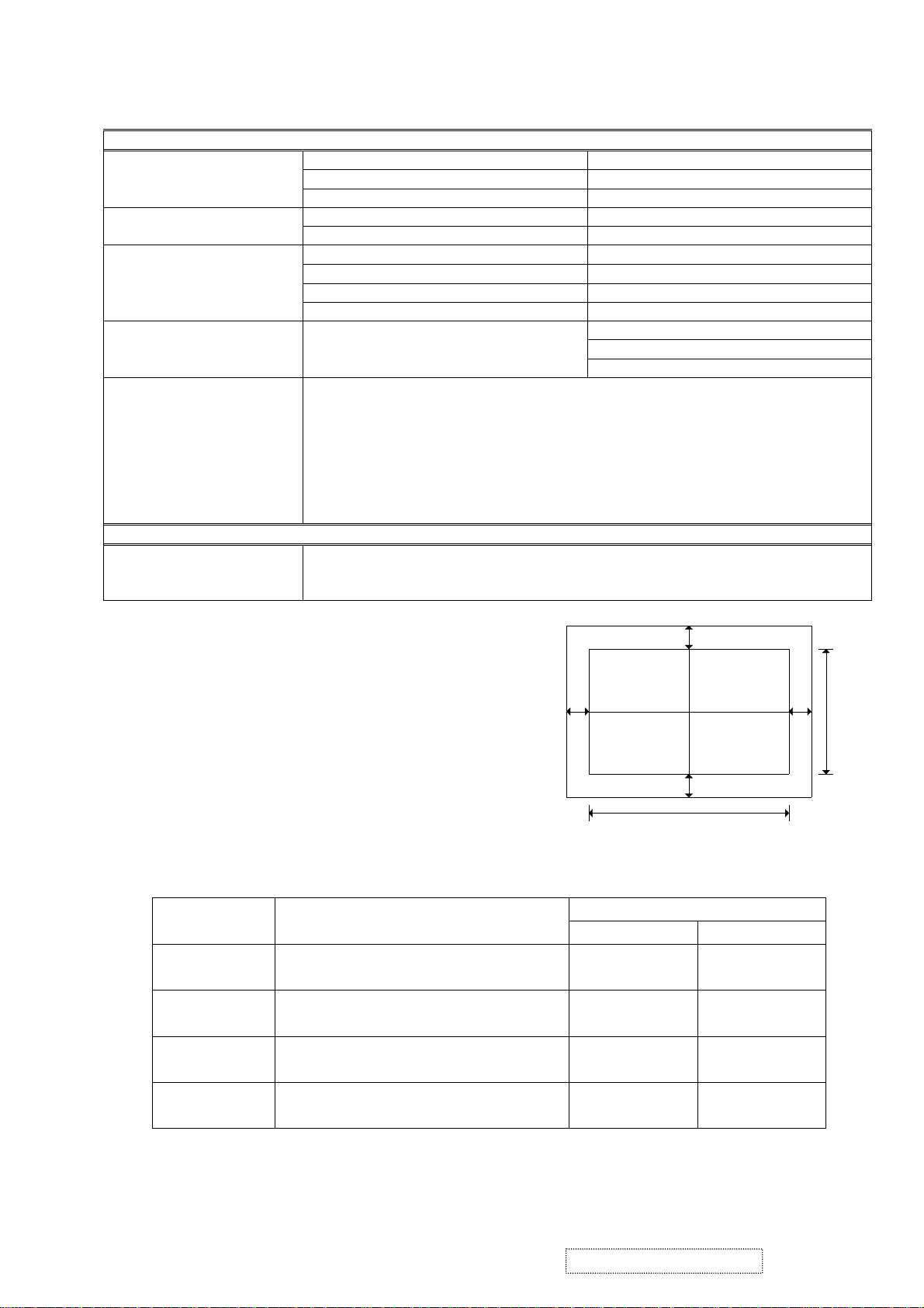
2.1.1 Picture size & position.
a. Picture size.
Input analog timing 1 ~ 25mode & DVI timing 1 ~ 22mode:
(Appendix A)
H-size: 408mm ± 1mm.
V-size: 306mm ± 1mm. (Extra 640x350)
b. Screen center.
b-1. 1600x1200: H ± 1mm, V ± 1mm.
b-2. Others mode: H ± 1.5mm, V ± 1mm.
c. Picture position (refer to FIG.2).
H-position:︱g3-g4︱ ≦ 1.5mm.
V-position:︱g1-g2︱ ≦ 1.5mm.
2.1.2 Luminance test.
Input1600x1200 / 60Hz & full white pattern at 100IRE, adjust brightness 100%, contrast 70%.
Color temperature x, y value
9300°K x=0.283 , y=0.298
6500°K x=0.313 , y=0.329
5400°K x=0.335 , y=0.350
5000°K x=0.346 , y=0.359
g3
g1
306mm
g4
g2
408mm
FIG. 2
Y (Luminance)
Analog DVI
2
CCT(max) = 10250°K, CCT(min) = 8500°K
CCT(max) = 6950°K, CCT(min) = 6100°K
CCT(max) = 5915°K, CCT(min) = 4935°K
CCT(max) = 53500°K, CCT(min) = 4700°K
> 140 cd/m
> 180 cd/m
> 180 cd/m
> 180 cd/m
> 140 cd/m2
2
> 180 cd/m2
2
> 180 cd/m2
2
> 180 cd/m2
ViewSonic Corporation Confidential
3
-
Do Not Copy VP201b/s-1

2.2. Adjustment control.
2.2.1 User control.
- Power switch.
- Function key.
“1” : Function select button.
“▼” : Adjustment button.
“▲” : Adjustment button.
“2” : Function select button.
2.2.2 OSD function.
Auto Image Adjust *
Contrast/Brightness:
Contrast, Brightness.
Input Select:
D-Sub, DVI-A, DVI-D.
Color Adjust:
9300K, 6500K (default), 5400, 5000, User Color (R, G, B).
Information:
Resolution, Horizontal Frequency, Vertical Frequency, Model Number, Serial Number, Web Site.
Manual Image Adjust:
H. / V. Position*
Sharpness*
3
2
2
(H. Position, V. Position), H. Size*2, Fine Tune*
, Scaling*3 (Fill Screen, Fill Aspect Ratio*
4
, 1:1).
2
,
Setup Menu:
Language:
Resolution Notice:
Input Priority:
OSD Position:
OSD Timeout:
OSD Background:
Memory Recall
Note:
2
*
3
*
4
*
English, French, German, Spanish, Italian, Finnish, Japanese, Traditional Chinese, Simplified Chinese.
Enable, Disable.
D-Sub, DVI-A, DVI-D, Auto Search.
H. Position, V. Position.
5SEC, 15SEC, 30SEC, 60SEC
On, Off.
These functions are not available in Digital mode; the setting is shaded and can't be selected.
When auto tuning, the image should not be blanking.
These functions are not available in 1600x1200 mode, the setting is shaded and can't be selected.
When the input signal is 4:3, the “Fill Aspect ratio” function is the size same as “Fill Screen”.
ViewSonic Corporation Confidential
4
-
Do Not Copy VP201b/s-1
2.3 Factory preset.
2.3.1 Special key (Hot key): Hold the following keys while powering on:
[1]. Main Menu.
[2]. Select next input. (Sequence: D-SUB → DVI-A → DVI-D)
[UP] or [DOWN] arrow. To immediately activate Contrast menu. It should be change to Brightness
[UP] + [DOWN] arrows. Recall Contrast or Brightness while in the Contrast or Brightness adjustment,
[1] + [2]. Toggle 720x400 and 640x400 mode when input 720x400 or 640x400 mode.
[1] + [UP] + [DOWN]. White Balance. (keep press 5 seconds)
[1] + [DOWN]. Power Lock / Power Unlock. (keep press 10 seconds )
[1] + [UP]. OSD Lock / OSD Unlock (keep press 10 seconds )
DC-Power + [2] + [UP]. Copy EDID to E
DC-Power + [1]. Factory mode. (Burn in mode on)
DC-Power + [2] + [DOWN]. Burn in mode on.
DC-Power + [UP] + [DOWN]. Burn in mode off.
DC-Power + [2]. All mode recall.
AC-Power on. Enter ISP mode.
2.3.2 All mode recall setting:
Contrast 70%.
Brightness 100%.
Color Temperature 6500K.
Scaling Full Screen.
Sharpness 0.
Input Priority Auto Search.
OSD H. Position 50%.
OSD V. Position 50%.
OSD Time Out 15 Sec
OSD Background On
Resolution Notice Enabled
720x400/640x400 720x400
User color. 50%.
Language. English.
Clear burn in mode.
Clear user mode table.
2.3.3 Factory shipment setting:
OSD by push button [2].
or recall both of Contrast and Brightness when the OSD is not open.
(only used 1024x768/75Hz, 16 Grays)
Main power switch: On.
AC power button: Off.
Others setting same as “All mode recall” setting.
2
PROM.
ViewSonic Corporation Confidential
5
-
Do Not Copy VP201b/s-1

2.4. Environmental conditions.
2.4.1 Temperature and humidity at operation : 0
o
C ~ 40oC.
20% ~ 90% RH (Non condensing).
o
2.4.2 Temperature and humidity at storage : -20
C ~ 60oC.
5 ~ 90% RH (Non condensing).
2.4.3 Vibration test (packaged) :
Vibration Frequency
Acceleration
Sweep time
Test time
: 1G.
: 1 oct. / min.
: 60 min per axis, total 3 axis.
: 5 ~ 250Hz.
2.4.4 Drop test (packaged) : 76.2cm height.
1 corner, 3 edges, 6 faces.
2.4.5 Altitude : Operating : 0 ~ 3000 feet.
Non-operating : 0 ~ 12000 feet.
ViewSonic Corporation Confidential
6
-
Do Not Copy VP201b/s-1
Appendix A: Timing of inputs signals / nominal input level spec / Timing.
Timing of input signals, Input level specification.
A. Input signal:
a. Analog R / G / B (0.7Vp-p/75 ohm) Positive.
b. Digital R /G / B DVI rev. 1.0 (TMDS single link)
c. H & V separate Sync: TTL level; Polarity: Positive or Negative.
d. H & V composite Sync: TTL level; Polarity: Positive or Negative.
B. Input signal connector:
a. Analog video input:
Pin Pin assignment Pin Pin assignment
1 Red video 9 +5V for DDC
2 Green video 10 GND
3 Blue video 11 GND
4 GND 12 DDC SDA
5 GND 13 H SYNC
6 Red video return 14 V SYNC
7 Green video return 15 DDC SCL
8 Blue video return
Pin5: For cable connection detect.
b. Digital video input:
Pin Pin assignment Pin Pin assignment Pin Pin assignment
1 TMDS data 2- 9 TMDS data 1- 17 TMDS data 02 TMDS data 2+ 10 TMDS data 1+ 18 TMDS data 0+
3 TMDS data 2 shield 11 TMDS data 1 shield 19 TMDS data 0 shield
4 NC 12 NC 20 NC
5 NC 13 NC 21 NC
6 DDC clock 14 +5V power 22 TMDS clock shield
7 DDC data 15 GND 23 TMDS clock +
8 Analog V-SYNC 16 Hot Plug Detect 24 TMDS clock C1 Analog R C2 Analog G C3 Analog B
C4 Analog H-SYNC C5 Analog Ground
Pin15: For cable connection detect.
ViewSonic Corporation Confidential
7
-
Do Not Copy VP201b/s-1

C. Analog timing chart.
Mode No. 1 2 3 4 5 6 7 8 9 10
TEXT
Mode Name
Horizontal Freq. 31.468 31.469 35.000 37.861 37.500 43.269 31.469
Video clock Freq. 25.175 25.175 30.240 31.500 31.500 36.000 28.322 36.000 40.000 50.000
Sync. Polarity
H. total (Dots) 800 800 864 832 840 832 900 1024 1056 1040
H. sync. (Dots) 96 96 64 40 64 56 108 72 128 120
H. back porch (Dots) 48 48 96 128 120 80 54 128 88 64
H. active (Dots) 640 640 640 640 640 640 720 800 800 800
H. front porch (Dots) 16 16 64 24 16 56 18 24 40 56
Vertical Freq. (Hz) 70.087 59.940 66.667 72.809 75.000 85.008 70.087 56.250 60.317 72.188
Sync. Polarity
V. total (Lines) 449 525 525 520 500 509 449 625 628 666
V. sync. (Lines) 2 2 3 3 3 3 2 2 4 6
V. back porch (Lines) 60 33 39 28 16 25 35 22 23 23
V. active (Lines) 350 480 480 480 480 480 400 600 600 600
V. front porch (Lines) 37 10 3 9 1 1 12 1 1 37
Mode No.
Mode Name
Horizontal Freq. (KHz) 46.875 53.674
Video clock Freq. 49.500 56.250 57.285 65.000 75.000 78.084 78.750 94.500 108.00 135.00
Sync. Polarity
H. total (Dots) 1056 1048 1152 1344 1328 1344 1312 1376 1688 1688
H. sync. (Dots) 80 64 64 136 136 136 96 96 112 144
H. back porch (Dots) 160 152 224 160 144 160 176 208 248 248
H. active (Dots) 800 800 832 1024 1024 1024 1024 1024 1280 1280
H. front porch (Dots) 16 32 32 24 24 24 16 48 48 16
Vertical Freq. (Hz) 75.000 85.061 74.553 60.004 70.069 72.082 75.029 84.997 60.020 75.025
Sync. Polarity
V. total (Lines) 625 631 667 807 806 806 800 808 1066 1066
V. sync. (Lines) 3 3 3 6 6 6 3 3 3 3
V. back porch (Lines) 21 27 37 29 29 29 28 38 38 38
V. active (Lines) 600 600 624 768 768 768 768 768 1024 1024
V. front porch (Lines) 1 1 3 3 3 3 1 1 1 1
640 x
350
VESA
800 x
600
VESA
640 x
480
+ - - - - - - + + +
- - - - - - + + + +
11 12 13 14 15 16 17 18 19 20
VESA
800 x
600
+ + - - - - + + + +
+ + - - - - + + + +
MAC
640 x
480
MAC
832 x
624
49.727
VESA
640 x
480
VESA
1024 x
768
48.363
VESA
640 x
480
VESA
1024 x
768
56.476 58.099
VESA
640 x
480
XGA
1024 x
768
TEXT
720 x
400
VESA
1024 x
768
60.023 68.677 63.981 79.976
VESA
800 x
600
35.156
VESA
1024 x
768
VESA
800 x
600
37.879 48.077
VESA
1280 x
1024
VESA
800 x
600
VESA
1280 x
1024
ViewSonic Corporation Confidential
8
-
Do Not Copy VP201b/s-1
Mode No.
Mode Name
Horizontal Freq. (KHz) 91.146
Video clock Freq. 157.50 74.250 162.00 189.00 202.500
Sync. Polarity
H. total (Dots) 1728 1650 2160 2160 2160
H. sync. (Dots) 160 40 192 192 192
H. back porch (Dots) 224 270 304 304 304
H. active (Dots) 1280 1280 1600 1600 1600
H. front porch (Dots) 64 60 64 64 64
Vertical Freq. (Hz) 85.024 60.000 60.000 70.000 75.000
Sync. Polarity
V. total (Lines) 1072 750 1250 1250 1250
V. sync. (Lines) 3 5 3 3 3
V. back porch (Lines) 44 20 46 46 46
V. active (Lines) 1024 720 1200 1200 1200
V. front porch (Lines) 1 5 1 1 1
21 22 23 24 25 26 27 28 29 30
VESA
1280 x
1024
HDTV
1280 x
720
45.000
+ - + + +
+ - + + +
VESA
1600 x
1200
75.000 87.500 93.750
VESA
1600 x
1200
VESA
1600 x
1200
ViewSonic Corporation Confidential
9
-
Do Not Copy VP201b/s-1
D. Digital timing chart.
Mode No. 1 2 3 4 5 6 7 8 9 10
TEXT
Mode Name
Horizontal Freq. 31.468 31.468 31.469 37.861 37.500 43.269 31.469
Video clock Freq. 25.175 25.175 25.175 31.500 31.500 36.000 28.322 36.000 40.000 50.000
Sync. Polarity
H. total (Dots) 800 800 800 832 840 832 900 1024 1056 1040
H. sync. (Dots) 96 96 96 40 64 56 108 72 128 120
H. back porch (Dots) 48 48 48 128 120 80 54 128 88 64
H. active (Dots) 640 640 640 640 640 640 720 800 800 800
H. front porch (Dots) 16 16 16 24 16 56 18 24 40 56
Vertical Freq. (Hz) 70.087 70.087 59.940 72.809 75.000 85.008 70.087 56.250 60.317 72.188
Sync. Polarity
V. total (Lines) 449 449 525 520 500 509 449 625 628 666
V. sync. (Lines) 2 2 2 3 3 3 2 2 4 6
V. back porch (Lines) 60 35 33 28 16 25 35 22 23 23
V. active (Lines) 350 400 480 480 480 480 400 600 600 600
V. front porch (Lines) 37 12 10 9 1 1 12 1 1 37
Mode No.
Mode Name
Horizontal Freq. (KHz) 46.875 53.674 48.363
Video clock Freq. 49.500 56.250 65.000 75.000 78.084 78.750 94.500 108.00 135.00 157.50
Sync. Polarity
H. total (Dots) 1056 1048 1344 1328 1344 1312 1376 1688 1688 1728
H. sync. (Dots) 80 64 136 136 136 96 96 112 144 160
H. back porch (Dots) 160 152 160 144 160 176 208 248 248 224
H. active (Dots) 800 800 1024 1024 1024 1024 1024 1280 1280 1280
H. front porch (Dots) 16 32 24 24 24 16 48 48 16 64
Vertical Freq. (Hz) 75.000 85.061 60.004 70.069 72.082 75.029 84.997 60.020 75.025 85.024
Sync. Polarity
V. total (Lines) 625 631 807 806 806 800 808 1066 1066 1072
V. sync. (Lines) 3 3 6 6 6 3 3 3 3 3
V. back porch (Lines) 21 27 29 29 29 28 38 38 38 44
V. active (Lines) 600 600 768 768 768 768 768 1024 1024 1024
V. front porch (Lines) 1 1 3 3 3 1 1 1 1 1
640 x
350
+ - - - - - - + + +
- + - - - - + + + +
11 12 13 14 15 16 17 18 19 20
VESA
800 x
600
+ + - - - + + + + +
+ + - - - + + + + +
VGA
640 x
400
VESA
800 x
600
VESA
640 x
480
VESA
1024 x
768
VESA
640 x
480
VESA
1024 x
768
56.476 58.099
VESA
640 x
480
XGA
1024 x
768
VESA
640 x
480
VESA
1024 x
768
60.023 68.677 63.981 79.976 91.146
TEXT
720 x
400
VESA
1024 x
768
VESA
800 x
600
35.156
VESA
1280 x
1024
VESA
800 x
600
37.879 48.077
VESA
1280 x
1024
VESA
800 x
600
VESA
1280 x
1024
ViewSonic Corporation Confidential
10
-
Do Not Copy VP201b/s-1

Mode No.
Mode Name
Horizontal Freq. (KHz)
Video clock Freq. 74.250 162.00
Sync. Polarity
H. total (Dots) 1650 2160
H. sync. (Dots) 40 192
H. back porch (Dots) 270 304
H. active (Dots) 1280 1600
H. front porch (Dots) 60 64
Vertical Freq. (Hz) 60.000 60.000
Sync. Polarity
V. total (Lines) 750 1250
V. sync. (Lines) 5 3
V. back porch (Lines) 20 46
V. active (Lines) 720 1200
V. front porch (Lines) 5 1
21 22 23 24 25 26 27 28 29 30
HDTV
1280 x
720
45.000
VESA
1600 x
1200
75.000
- +
- +
ViewSonic Corporation Confidential
11
-
Do Not Copy VP201b/s-1

a. 128 bytes of EDID code for VP201b analog.
0 1 2 3 4 5 6 7 8 9
0 00 FF FF FF FF FF FF 00 5A 63
10 11 69 01 01 01 01 01 0D 01 03
20 0E 29 1F 78 2A 4E 95 A1 57 4C
30 94 26 1C 50 54 BF EF 80 A9 40
40 81 80 81 40 71 4F 61 59 45 59
50 31 59 A9 4F 48 3F 40 30 62 B0
60 32 40 40 C0 13 00 98 32 11 00
70 00 1E 00 00 00 FF 00
80 30 33 30 31 30 30 30 30 31 0A
90 00 00 00 FD 00 32 55 1E 5F 15
100 00 0A 20 20 20 20 20 20 00 00
110 00 FC 00 56 50 32 30 31 62 0A
120 20 20 20 20 20 20 00 B4
Note: *4 (77 ~ 79)
77 78 79 Remark
Standard packing
individual head packing & multi-packing
b. 128 bytes of EDID code for VP201b digital.
0 1 2 3 4 5 6 7 8 9
0 00 FF FF FF FF FF FF 00 5A 63
10 11 69 01 01 01 01 01 0D 01 03
20 80 29 1F 78 2A 4E 95 A1 57 4C
30 94 26 1C 50 54 BF EF 80 A9 40
40 81 80 81 40 71 4F 61 59 45 59
50 31 59 31 0A 48 3F 40 30 62 B0
60 32 40 40 C0 13 00 98 32 11 00
70 00 1E 00 00 00 FF 00
80 30 33 30 31 30 30 30 30 31 0A
90 00 00 00 FD 00 32 55 1E 5C 11
100 00 0A 20 20 20 20 20 20 00 00
110 00 FC 00 56 50 32 30 31 62 0A
120 20 20 20 20 20 20 00 B4
4
*
*4 *
41 32 31 A21
41 32 44 A2D
4
*
*4 *
4
4
Note: *4 (77 ~ 79)
77 78 79 Remark
Standard packing
individual head packing & multi-packing
41 32 31 A21
41 32 44 A2D
ViewSonic Corporation Confidential
12
-
Do Not Copy VP201b/s-1

c. 128 bytes of EDID code for VP201s analog.
0 1 2 3 4 5 6 7 8 9
0 00 FF FF FF FF FF FF 00 5A 63
10 18 0C 01 01 01 01 01 0D 01 03
20 0E 29 1F 78 2A 4E 95 A1 57 4C
30 94 26 1C 50 54 BF EF 80 A9 40
40 81 80 81 40 71 4F 61 59 45 59
50 31 59 A9 4F 48 3F 40 30 62 B0
60 32 40 40 C0 13 00 98 32 11 00
70 00 1E 00 00 00 FF 00 41 32 55
80 30 33 30 31 30 30 30 30 31 0A
90 00 00 00 FD 00 32 55 1E 5F 15
100 00 0A 20 20 20 20 20 20 00 00
110 00 FC 00 56 50 32 30 31 0A 20
120 0A 20 20 20 20 20 00 B4
d. 128 bytes of EDID code for VP201s digital.
0 1 2 3 4 5 6 7 8 9
0 00 FF FF FF FF FF FF 00 5A 63
10 18 0C 01 01 01 01 01 0D 01 03
20 80 29 1F 78 2A 4E 95 A1 57 4C
30 94 26 1C 50 54 BF EF 80 A9 40
40 81 80 81 40 71 4F 61 59 45 59
50 31 59 31 0A 48 3F 40 30 62 B0
60 32 40 40 C0 13 00 98 32 11 00
70 00 1E 00 00 00 FF 00 41 32 55
80 30 33 30 31 30 30 30 30 31 0A
90 00 00 00 FD 00 32 55 1E 5C 11
100 00 0A 20 20 20 20 20 20 00 00
110 00 FC 00 56 50 32 30 31 0A 20
120 20 20 20 20 20 20 00 B4
ViewSonic Corporation Confidential
13
-
Do Not Copy VP201b/s-1
e. 128 bytes of EDID code for VP211b analog.
0 1 2 3 4 5 6 7 8 9
0 00 FF FF FF FF FF FF 00 5A 63
10 11 6A 01 01 01 01 01 0D 01 03
20 0E 2B 20 78 2A EE 95 A3 54 4C
30 99 26 0F 50 54 BF EF 80 A9 40
40 A9 4F 81 99 81 59 71 4F 61 59
50 45 59 31 59 48 3F 40 30 62 B0
60 32 40 40 C0 13 00 B0 44 11 00
70 00 1E 00 00 00 FF 00
4
*
*
4
*
80 30 33 30 31 30 30 30 30 31 0A
90 00 00 00 FD 00 32 55 1E 5F 15
100 00 0A 20 20 20 20 20 20 00 00
110 00 FC 00 56 50 32 31 31 62 0A
120 20 20 20 20 20 20 00 B4
Note: *4 (77 ~ 79)
77 78 79 Remark
Standard packing
individual head packing & multi-packing
41 32 32 A22
41 32 45 A2E
f. 128 bytes of EDID code for VP211b digital.
0 1 2 3 4 5 6 7 8 9
0 00 FF FF FF FF FF FF 00 5A 63
10 11 6A 01 01 01 01 01 0D 01 03
20 80 2B 20 78 2A EE 95 A3 54 4C
30 99 26 0F 50 54 BF EF 80 A9 40
40 81 99 81 59 71 4F 61 59 45 59
50 31 59 31 0A 48 3F 40 30 62 B0
60 32 40 40 C0 13 00 B0 44 11 00
70 00 1E 00 00 00 FF 00
4
*
*4 *
80 30 33 30 31 30 30 30 30 31 0A
90 00 00 00 FD 00 32 55 1E 5C 11
100 00 0A 20 20 20 20 20 20 00 00
110 00 FC 00 56 50 32 31 31 62 0A
120 20 20 20 20 20 20 00 B4
4
4
Note: *4 (77 ~ 79)
77 78 79 Remark
Standard packing
individual head packing & multi-packing
41 32 32 A22
41 32 45 A2E
ViewSonic Corporation Confidential
14
-
Do Not Copy VP201b/s-1
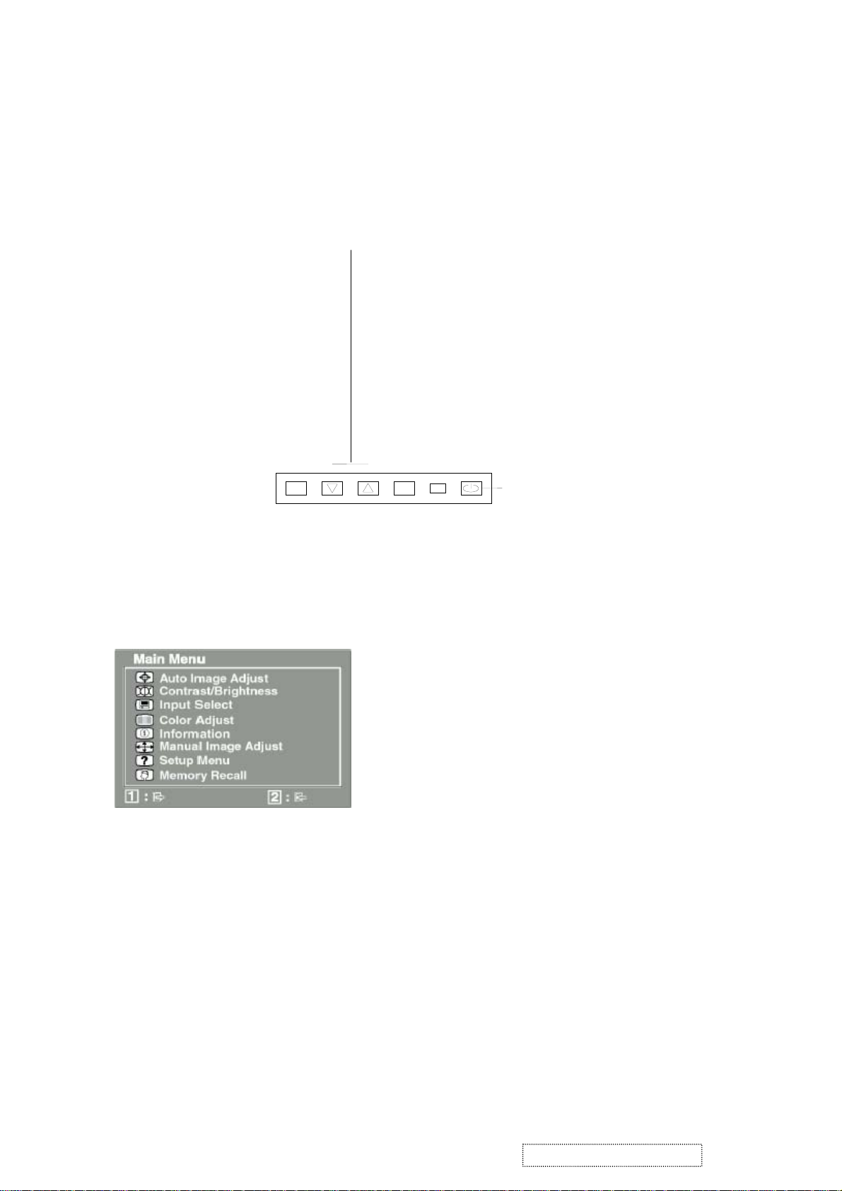
3. Front Panel Function Control Description
A. User control.
B. OSD (on screen display) function control method.
Scrolls through menu options and
adjusts the displayed control.
Also a shortcut to display the
Contrast adjustment control screen.
Display the Main Menu or exits the control screen
and saves adjustments
Displays the control screen
for the highlighted control.
Also toggles between two
controls on some screens.
Also a shortcut to toggle
analog and digital
Power light
Green – ON
Orange – Power Saving
1
1. To display the main menu, press button “1”.
2. To select a control you want to adjust, press ▲ or ▼ to scroll up or down the main menu.
3. After the control is selected, press button “2”.
4. To adjust the control, press the ▲ or ▼ button.
5. To save the adjustments and exit the menu, press button “1” twice.
2
Power On / Off
ViewSonic Corporation Confidential
15
-
Do Not Copy VP201b/s-1
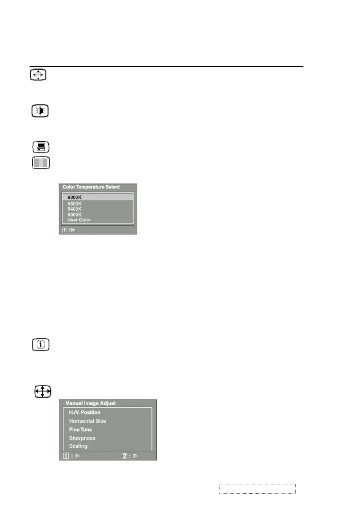
C. Main menu controls.
Adjust the menu items shown below by using the up ▲ and down ▼ buttons.
Control explanation.
Auto Image Adjust automatically sizes, centers, and fine tunes the video signal to eliminate waviness and distortion.
Press the [2] button to obtain a sharper image.
Note: Auto Image Adjust works with most common video cards. If this function does not work
on your LCD display, then lower the video refresh rate to 60Hz and set the resolution to
its pre-set value.
Contrast adjusts the difference between the image background (black level) and the foreground (white level).
Brightness adjusts background black level of the screen image.
Input Select allows you to toggle between an analog and a digital signal.
Color Adjust provides several color adjustment modes: preset color temperatures and RGB which allows you to adjust
red (R), green (G), and blue (B) separately. The factory setting for this product is 6500K (6500 Kelvin).
9300K ─ Adds blue to the screen image for cooler white (used in most office settings with fluorescent lighting).
6500K ─ Adds red to the screen image for warmer white and richer red.
5400K ─ Adds blue and green to the screen image for a darker color.
User Color ─ Individual adjustments for red (R), green (G), and blue (B).
1. To select color (R, G or B) press button [2].
2. To adjust selected color, press ▼ or ▲.
Important: If you select RECALL from the Main Menu when the product is set to a Preset Timing Mode, colors
return to the 6500K factory preset.
Information displays the timing mode (video signal input) coming from the graphics card in your computer. See your
graphic card’s user guide for instructions on changing the resolution and refresh rate (vertical frequency).
Note: VESA 1600x1200@60Hz (recommended) means that the resolution is 1600x1200 and the refresh
rate is 60 Hertz.
Manual Image Adjust displays the Manual Image Adjust menu.
ViewSonic Corporation Confidential
16
-
Do Not Copy VP201b/s-1
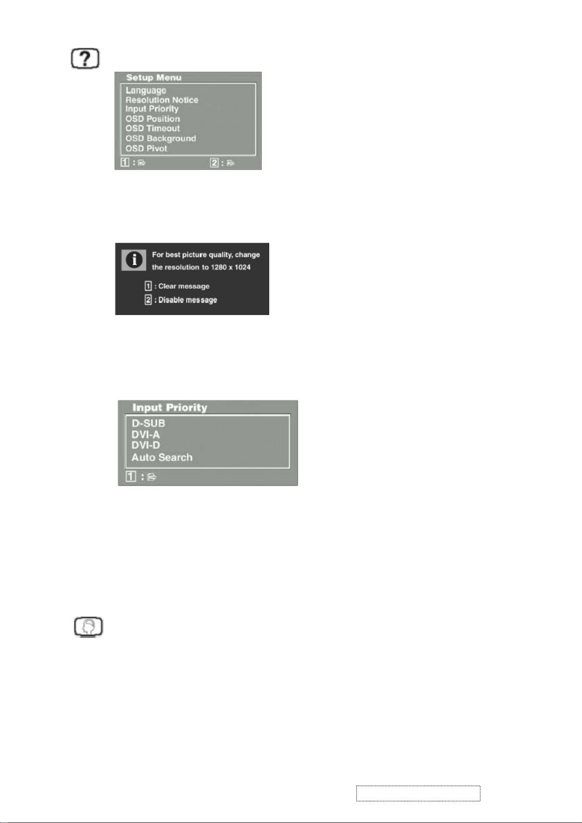
Setup Menu displays the menu shown below.
The Setup Menu controls are explained below:
Language allows you to choose the language used in the menus and control screens.
Resolution Notice displays the Resolution Notice menu shown below.
Resolution Notice advises the optimal resolution to use.
Input Priority If multiple computers will be connected to the display, this function can be used to select which
computer has priority Depending on the selected Input Priority, the display will do a one time detection
for available inputs when first powered on.
OSD Position allows you to move the on-screen display menus and control screens.
OSD Timeout sets the length of time of on-screen display screen is displayed. For example, with a “15 second”
setting, if a control is not pushed within 15 seconds, the display screen disappears.
OSD Background allows you to turn the On-Screen-Display background on or off.
OSD Pivot This function is used to rotate the OSD menu, when the display is changed from Landscape to Portrait
mode.
Memory Recall returns adjustments to the original factory settings if the display is operating in a factory Preset
Timing Mode listed in this user guide.
Exception: This control does not affect changes made with the User Color control.
ViewSonic Corporation Confidential
17
-
Do Not Copy VP201b/s-1

4. Circuit Description
1. Power supply (DC/DC Converter):
1.1 IC251 BA9741F is a two-channel switching regulator controller that uses PWM method. For DC to DC
conversion for step-down. It converts a 12V DC into regulated and stable output voltage of 5V.
1.2 Regulator:
IC252, IC253, IC254, IC255 function is to convert 5V into regulated and stable O/P of 3.3V and 2.5V.
IC252 converts 5V to 2.5V; converts 5V to 3.3V; IC253, IC254, IC255.
2. DDC data select:
2.1 IC601 is save D-SUB DDC data.
2.2 IC606 save DVI-A analog DDC data, IC605 save DVI-D digit DDC data.
IC604 is triple 2 channel analog multiplexes / de-multiplexes, IC604 pin 10 & 11 is “Lo” select IC605 DDC data,
IC604 pin 10 & 11 is “Hi” select IC606 DDC data.
3. ADC (Analog):
The IC608 AD9888 is a complete 8-bit, 205MSPS monolithic analog interface optimized for capturing RGB graphics signal
from PC. The IC608 have two input source (D-SUB & DVI-A), the input source control by I
4. TMDS (DVI):
The IC609 THC63DV161 is a TMDS receiver compliant with DVI Rev. 1.0.
The IC609 turn on/off control by pin 2 “DPD” from IC401 scaler.
5. Scaler:
The PW166B image processor is a highly integrated “system-on-a-chip” that interfaces analog, digital, and video inputs in
virtually any format to a digital projection system or multimedia display.
Any embedded SDRAM frame buffer and memory controller perform frame rate conversion. Computer images from VGA to
UXGA at almost any refresh rate can be resized to fit on a fixed-frequency target display device with any resolution up to
UXGA with full 24-bit color.
The PW166B includes advanced second generation image scaling that provides completely programmable, horizontal and
vertical image scaling.
The PW166B also includes advanced second-generation sync decoding which provides full support for a wide variety of sync
types. This includes interlaced, progressive, sync-on-green, and TMDS DE (Data Enable) only.
An integrated OSD controller provides bit-mapped based OSD with 16 colors from a 64K color palette. The OSD controller
supports transparent and translucent functions.
The Graphics Port (GPort) captures computer graphics inputs with very high input bandwidth through an external IC608
Analog-To-Digital converter (ADC) or IC609 digital interface receiver.
The DPort is designed to be connected directly to LVDS (IC501, IC502).
The output timing is fully programmable and is independent of the input timing.
An on-chip 80x86 microprocessor with custom features for image processing applications is provided. Built in port interrupts,
General Purpose I/O (GPIO), UART, IR Decoders, Timers and PWM Generator provide a full featured hardware base to build
on.
6. LVDS Transmitter:
The IC501, IC502 transmitter converts 28 bits of CMOS/TTL data into LVDS (Low Voltage Differential Signaling) data stream.
A phase-locked transmit clock is transmitted in parallel with the data streams over a fifth LVDS link.
7. USB HUB Controller:
IC951 is a high speed USB HUB controller, this single-chip device incorporates one upstream and four downstream USB
transceivers.
IC951 CY7C65640 includes interface signals for external port power switches. The power switching and over-current detection
of downstream ports is managed by control pins connected to an external power switch device by IC952 & IC953.
IC954 is an EEPROM VID & PID configured.
2
C from IC401 scaler.
ViewSonic Corporation Confidential
18
-
Do Not Copy VP201b/s-1
 Loading...