

Page 1

Service Manual
Model No. VLCDS25973-2W/3W
19” Color TFT LCD Display
ViewSonic VP191b/s-1
ViewSonic
381 Brea Canyon Road, Walnut, California 91789 USA - (800) 888-8583
(VP191b/s_SM_678 Rev. 1c Oct. 2004)
Page 2
Copyright
Copyright
¤
2004 by ViewSonic Corporation. All rights reserved. No part of this publication may be
reproduced, transmitted, transcribed, stored in a retrieval system, or translated into any language or
computer language, in any form or by any means, electronic, mechanical, magnetic, optical, chemical,
manual or otherwise, without the prior written permission of ViewSonic Corporation.
Disclaimer
ViewSonic makes no representations or warranties, either expressed or implied, with respect to the
contents hereof and specifically disclaims any warranty of merchantability or fitness for any particular
purpose. Further, ViewSonic reserves the right to revise this publication and to make changes from time
to time in the contents hereof without obligation of ViewSonic to notify any person of such revision or
changes.
Trademarks
ViewSonic is a registered trademark of ViewSonic Corporation.
All other trademarks used within this document are the property of their respective owners.
Optiquest is a registered trademark of ViewSonic Corporation.
Revision History
Revision Date Description Of Changes Approval
i
ViewSonic Corporation Confidential
-
Do Not Copy VA521
DCN Number ECR Number
Documents Number
Description of Changes EditorRevision SM Editing Date
1a
06/28/03
3379
Initial Release
F. Fellen
1c
10/18/04
4775
1b
04/23/04
4290
A. Lu
Cost Down Chassis change
4801
Change Panel From FJ FLC48SXC8V-11A SXGA 25ms
To FJ FLC48SXC8V-11AA 16ms
A. Lu
4226
Page 3

TABLE OF CONTENTS
2. Specification
3. Front Panel Function Control Description
4. Circuit Description
6. Trouble Shooting Flow Chart
9. Block Diagram
10. Schematic Diagrams
7. Recommended Spare Parts List
1. Precautions and Safety Notices
5. Adjusting Procedure
8. Exploded Diagram And Spare Parts List
11. PCB Layout Diagrams
1
3
7
17
19
42
46
54
69
70
76
ii
ViewSonic Corporation Confidential
-
Do Not Copy VP191b/s
Page 4

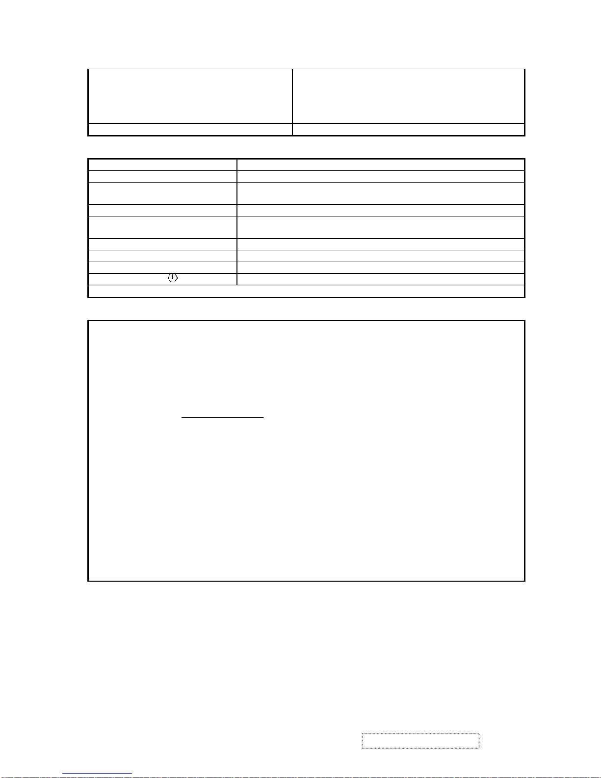
1. Appropriate Operation
(1) Turn off the product before cleaning.
(2) Use only a dry soft cloth when cleaning the LCD panel surface.
(3) Use a soft cloth soaked with mild detergent to clean the display housing.
(4) Use only high quality and safety approved AC power cord.
(5) Disconnect the power plug from AC outlet if the product is not used for a long period of time.
(6) If smoke, abnormal noise, or strange odor is present, immediately switch the LCD display off.
(7) Do not touch the LCD panel surface with sharp or hard objects.
(8) Do not place heavy objects on the LCD display, video cable, or power cord.
(9) Do not use abrasive cleaners, waxes or solvents for your cleaning.
(10) Do not operate the product under the following conditions:
- Extremely hot, cold or humid environment.
- Areas susceptible to excessive dust and dirt.
- Near any appliance generating a strong magnetic field.
- Place in direct sunlight.
2. Caution
No modification of any circuit should be attempted. Service work should only be performed after you are thoroughly familiar
with all of the following safety checks and servicing guidelines.
3. Safety Check
Care should be taken while servicing this LCD display. Because of the high voltage used in the inverter circuit, the voltage is
exposed in such areas as the associated transformer circuits.
4. LCD Module Handling Precautions
4.1 Handling Precautions
(1) Since front polarizer is easily damaged, pay attention not to scratch it.
(2) Be sure to turn off power supply when inserting or disconnecting from input connector.
(3) Wipe off water drop immediately. Long contact with water may cause discoloration or spots.
(4) When the panel surface is soiled, wipe it with absorbent cotton or other soft cloth.
(5) Since the panel is made of glass, it may break or crack if dropped or bumped on hard surface.
(6) Since CMOS LSI is used in this module, take care of static electricity and insure human earth when handling.
(7) Do not open nor modify the Module Assembly.
(8) Do not press the reflector sheet at the back of the module to any directions.
(9) In case if a Module has to be put back into the packing container slot after once it was taken out from the
container, do not press the center of the CCFL Reflector edge. Instead, press at the far ends of the CFL
Reflector edge softly. Otherwise the TFT Module may be damaged.
(10) At the insertion or removal of the Signal Interface Connector, be sure not to rotate nor tilt the Interface
Connector of the TFT Module.
1. Precautions and Safety Notices
1
ViewSonic Corporation Confidential
-
Do Not Copy VP191b/s
Page 5

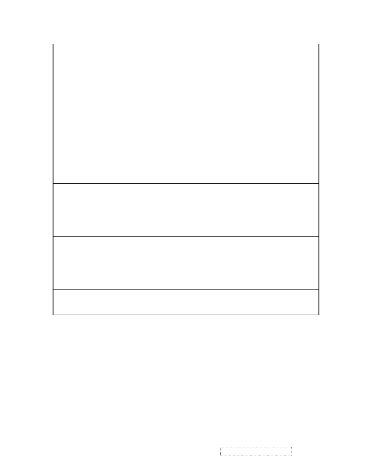
(11) After installation of the TFT Module into an enclosure (LCD monitor housing, for example), do not twist nor
bend the TFT Module even momentary. At designing the enclosure, it should be taken into consideration that
no bending/twisting forces are applied to the TFT Module from outside. Otherwise the TFT Module may be
damaged.
(12) Cold cathode fluorescent lamp in LCD contains a small amount of mercury. Please follow local ordinances or
regulations for disposal.
(13) Small amount of materials having no flammability grade is used in the LCD module. The LCD module should
be supplied by power complied with requirements of Limited Power Source (IEC60950 or UL1950), or be
applied exemption.
(14) The LCD module is designed so that the CFL in it is supplied by Limited Current Circuit (IEC60950 or
UL1950). Do not connect the CFL in Hazardous Voltage Circuit.
2
ViewSonic Corporation Confidential
-
Do Not Copy VP191b/s
Page 6
2-1 GENERAL SPECIFICATION
Test Resolution & Frequency 1280x1024 @ 60Hz
Test Image Size Full Size
Contrast and Brightness Controls
Factory Default:
Contrast = 50%, Brightness = 100%
2-2 VIDEO INTERFACE
Input Connector 1 (Analog 1) DB-15 (Analog), refer the appendix A
Input Connector 2 (Analog 2) DB-15 (Analog), refer the appendix A
Input Connector 3 (Digital) DVI-D (Digital), refer the appendix B
Default Input Connector Defaults to the first detected input
Video Cable Strain Relief Equal to twice the weight of the monitor for five minutes
Video Cable Connector DB-15 Pin out Compliant DDC 2B
Video Signals
1. Video RGB (Analog)
Separate, Composite, and Sync on Green
2. TMDS (Digital)
Video Impedance 75 Ohms (Analog), 100 Ohms (Digital)
Maximum PC Video Signal 950 mV with no damage to monitor
Maximum Mac Video Signal 1250 mV with no damage to monitor
Sync Signals TTL
DDC 2B Compliant with Revision 1.3
Sync Compatibility Separate Sync, Composite Sync, SOG
Video Compatibility
Shall be compatible with all PC type computers,
Macintosh computers, and after market video cards
Resolution Compatibility
640 x 350*
1
, 640 x 480, 720 x 400*1 (640 x 400*), 800 x
600, 832 x 624, 1024 x 768, 1152 x 864, 1152 x 870*
2
,
1280 x 720, 1280 x 960, 1280 x 1024
*1 The image vertical size might not be full screen.
But the image vertical position should be at the
center.
*2 Under 1152x870@60Hz or 72Hz, the OSD
information
shows on “1152x864”
Exclusions Not compatible with interlaced video
2. Specification
3
ViewSonic Corporation Confidential
-
Do Not Copy VP191b/s
Page 7
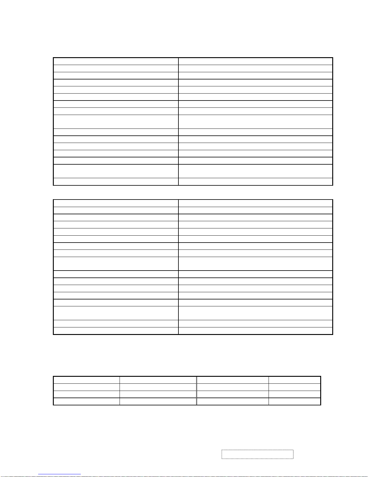
2-3 POWER SUPPLY
Internal Power Supply
Primary : LSE0204A1250
2
nd
source: Tiger power TOF 5001
Input Voltage Range 90 TO 264 VAC
Input Frequency Range 47.5 TO 63 HERTZ
Short Circuit Protection Output can be shorted without damage
Over Current Protection 7.0 A typical at 12.0 VDC
Leakage Current 3.5mA (Max) at 254VAC / 60Hz
EFFICIENCY 80 % typical at 115VAC Full Load
Fuse Internal and not user replaceable
Power Dissipation 50 Watts (typ)
Max Input AC Current 1.5 Arms @ 90VAC, 0.75 Arms @180VAC
INRUSH CURRENT (COLD START) 20 A @ 115VAC, 30 A(max) @230VAC
Power Supply Cold Start
Shall start and function properly when under full load,
with all combinations of input voltage, input frequency,
and operating temperature
Power Supply Transient Immunity
Shall be able to withstand an ANSI/IEEE C62.41-1980
6000V 200 ampere ring wave transient test with no
damage
Power Supply Line Surge Immunity
Shall be able to withstand 1.5 times nominal line voltage
for one cycle with no damage
Power Supply Missing Cycle Immunity
Shall be able to function properly, without reset or visible
screen artifacts, when ½ cycle of AC power is randomly
missing at nominal input
Power Supply Acoustics
The power supply shall not produce audible noise that
would be detectable by the user. Audible shall defined to
be in compliance with ISO 7779 (DIN EN27779:1991)
Noise measurements of machines acoustics. Power
Switch noise shall not be considered
US Type Power Cable
Separate 3-prong NEMA 5-15P type plug. Length =
1.8m. Connects to display.
Color = Black
European Type Power Cable
Schuko CEE7-7 type plug.
Length = 1.8m, Connects to display.
Color = Black
CCC Type Power Cable(Color, Black)
Separate 3-prong type plug.
Length = 1.8m. Connects to display.
PSE Type Power Cable(Color, Black)
Separate 2-prong NEMA 1-15P type plug. Length =
1.8m. Connects to display.
Power Saving Operation(Method) VESA DPMS Signaling
Power Consumption
On Mode < 50 W (max) / 40 W (typ)
Active Off < 2W
Recovery Time On Mode = N/A, Active Off < 3 sec
2-4 ELECTRICAL REQUIREMENT
Horizontal / Vertical Frequency
Horizontal Frequency 24 – 82 KHZ
Vertical Refresh Rate
50 – 85* HZ.
*1. FOR RESOLUTION 640X480, 800X600 AND
1024X768, THE VERTICAL REFRESH RATE UP
TO 85HZ; FOR THE REST RESOLUTIONS, THE
VERTICAL REFRESH RATE UP TO 75HZ.
*2. ALL THE 85HZ MODE PICTURE QUALITY
MIGHT BE WORSE THAN ≦75HZ MODE.
Maximum Pixel Clock 135 MHz
Sync Polarity Independent of sync polarity.
4
ViewSonic Corporation Confidential
-
Do Not Copy VP191b/s
Page 8
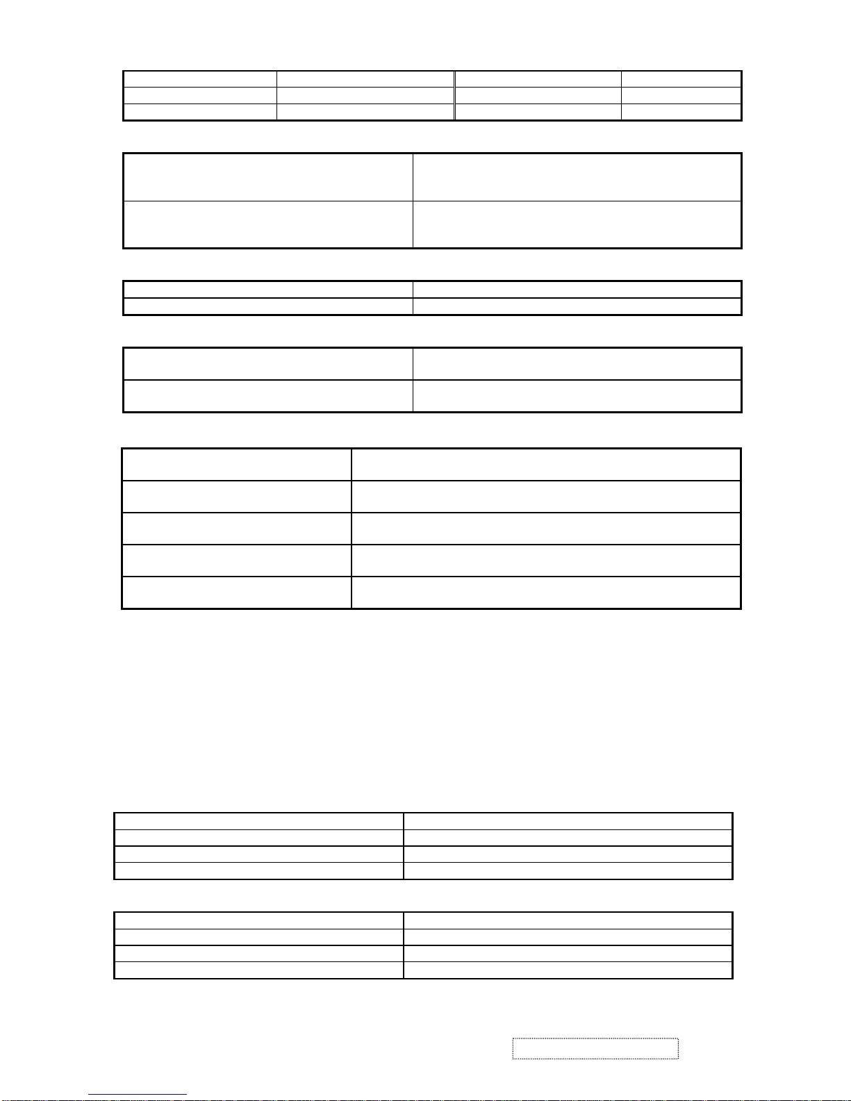
Timing Table
Item Timing Analog Digital
1 640 x 350 @ 70Hz, 31.5kHz Yes Yes
2 640 x 400 @ 60Hz, 31.5kHz Yes Yes
3 640 x 400 @ 70Hz, 31.5kHz Yes Yes
4 640 x 480 @ 50Hz, 24.7kHz Yes Yes
5 640 x 480 @ 60Hz, 31.5kHz Yes Yes
6 640 x 480 @ 67Hz, 35.0kHz Yes Yes
7 640 x 480 @ 72Hz, 37.9kHz Yes Yes
8 640 x 480 @ 75Hz, 37.5kHz Yes Yes
9 640 x 480 @ 85Hz, 43.27kHz Yes Yes
10 720 x 400 @ 70Hz, 31.5kHz Yes Yes
11 800 x 600 @ 56Hz, 35.1kHz Yes Yes
12 800 x 600 @ 60Hz, 37.9kHz Yes Yes
13 800 x 600 @ 75Hz, 46.9kHz Yes Yes
14 800 x 600 @ 72Hz, 48.1kHz Yes Yes
15 800 x 600 @ 85Hz, 53.7kHz Yes Yes
16 832 x 624 @ 75Hz, 49.7kHz Yes Yes
17 1024 x 768 @ 60Hz, 48.4kHz Yes Yes
18 1024 x 768 @ 70Hz, 56.5kHz Yes Yes
19 1024 x 768 @ 72Hz, 58.1kHz Yes Yes
20 1024 x 768 @ 75Hz, 60.0kHz Yes Yes
21 1024 x 768 @ 85Hz, 68.67kHz Yes Yes
22 1152 x 864 @ 75Hz, 67.5kHz Yes Yes
23 1152 x 870 @ 75Hz, 68.7kHz Yes Yes
24 1280 x 1024 @ 60Hz, 63.4kHz Yes Yes
25 1280 x 1024 @ 75Hz, 79.97kHz Yes Yes
26 1280x 720 @ 60Hz, 45kHz (HDTV) Yes Yes
Primary Presets
1280x1024 @ 60Hz
User Presets
Number of User Presets (recognized timings) Available: 10 presets total in FIFO configuration
Changing Modes
Maximum Mode Change Blank Time for image stability : 5 seconds (Max), excluding “Auto Adjust” time ●
●
●
●
Under DOS mode (640 x 350, 720 x 400 & 640 x 400), it should recall factory setting when execute “Auto
Adjust” by “0-Touch™”
The monitor needs to do “Auto Adjust” the first time a new mode is detected
(see section “0-Touch™ Function Actions”)
While running Change Mode, Auto Adjust or Memory Recall, the image shall blank
2-5 FRONT PANEL CONTROLS AND INDICATORS
Front Panel Hardware Controls
Power Switch (Front Head) Power Control, soft Power Switch.
Power LED (Front Head) Green – ON
Orange – Active Off
Dark = Soft Power Switch OFF
Front Panel Controls (Head)
[
] [ 1 ] [ 2 ] [▲] [▼]
[
] Power
[ 1 ] Button 1
[ 2 ] Button 2
5
ViewSonic Corporation Confidential
-
Do Not Copy VP191b/s
Page 9
[▲] Up arrow button
[▼] Down arrow button
Note: Power Button, Button 1 and Button 2 must be oneshot logic operation. (i.e. there should be no cycling)
Reaction Time OSD must fully appear within 0.5s after pushing Button 1
Short Cuts Function from the button(s)
[1] Main Menu
[2] Input Select
[▼] or [▲] to immediately activate Contrast menu. It should be change to Brightness
OSD by push button [2]
[▼]+ [▲] recall both of Contrast and Brightness to default
[1] + [2] toggle 720x400 and 640x400 mode when input 720x400 or 640x400
mode
[1] + [▼] + [▲] White Balance. (Not shown on user’s guide)
[1] + [▼] Power Lock
[1] + [▲] OSD Lock
[1] + [ ] Factory Mode
Remark : All the short cuts function are only available while OSD off
Main Menu Controls
Auto Image Adjust*
1
Contrast/Brightness
*3
Input Select
Analog 1, Analog 2, DVI-D
Color Adjust
9300K, 6500K(default), 5400K, 5000KUser Color [R, G, B]
Information
H Frequency, V Frequency, Resolution, Pixel Clock, Serial Number,
Model Number, “www.ViewSonic.com
” ]
Manual Image Adjust [Horizontal Size*
1
, H./V. Position*1, Fine Tune*1, Sharpness*2
Setup Menu
Language [English, French, German, Spanish, Italian, Finnish, Japanese, Simplified Chinese, Traditional
Chinese], Resolution Notice, Input Priority
[Analog1Æ Analog 2ÆDVI-D, Analog1ÆDVI-DÆ Analog 2, Analog 2Æ Analog 1ÆDVI-D, Analog
2ÆDVI-DÆ Analog 1, DVI-DÆ Analog 1Æ Analog 2, DVI-DÆ Analog 2Æ Analog 1, Disable], OSD
Position, OSD Timeout, OSD Background, OSD Pivot*
4
MEMORY RECALL
*
1
These functions are not available in Digital Mode
*
2
These functions are not available under Native Resolution Mode
*3
These functions setting can be recalled to default by [▼]+[▲]
*4
Both of automatically and manually OSD pivot should be available.
[Remark] Please refer to the detail in the Appendix C
6
ViewSonic Corporation Confidential
-
Do Not Copy VP191b/s
Page 10
Function descriptions
OSD Lock short cuts function for the buttons
The OSD lock will be activated by pressing the front panel control buttons "(1), & (▲)" for 10 seconds. If the user
then tries to access the OSD by pressing any of the buttons "1", "▼", "▲", "2" a message will appear on the screen
for 3 seconds showing "OSD Locked". The OSD lock will be deactivated by pressing the front panel control
buttons "(1), & (▲)" again for 10 seconds.
Note1: When the OSD is locked will lock all functions.
Note 2: Status bar indicating OSD Lock or Unlock is in progress and when complete it will indicate “OSD
Locked”
Note 3: OSD Lock should not lock Power Button and Power Lock function
Power Lock short cuts function for the buttons
The power button lock will be activated by pressing the front panel control buttons "(1), & (▼)" for 10 seconds.
Locking the power button means that the user won't be able to turn off the LCD while the power button is locked.
If the user presses the power button while it is locked, a message will appear on the screen for 3 seconds showing
"Power Button Locked". It also means that with the power button locked, the LCD would automatically turn back
"On" when power is restored after a power failure. If the power button is not in the locked mode, then power
should return to it's previous state when power is restored after a power failure. The power button lock will be
deactivated by pressing the front panel control buttons "(1), & (▼)" again for 10 seconds.
Note 1: Status bar indicating Power Button lock or unlock is in progress and when complete it will indicate
“Power Button Locked”
Note 2: Power should only be lockable in the “On State”
Memory Recall Actions
Memory Recall action on the analog and digital mode as below
1. Recall white balance to factory setting
2. Set the factory defaults as shown in Section 4-8
3. Clean all the mode setting buffer
4. Execute Auto Image Adjust
Note: Memory Recall should have no effect for Language, Power Lock, User Color Settings
Resolution Notice Actions
1. Resolution Notice OSD should show on screen after changing to non-native mode for 30 sec
2. The OSD should disappear after 10 sec or by pushing button [1] or [2]
Resolution Notice function should be disabled when push button [2] under Resolution Notice OSD
0-Touch™ Function Actions
1. Execute Auto Image Adjust when new mode detected, and save the settings to buffer for further use
2. It should be reset by Memory Recall function
(Should not reset by power off, power unplug and others)
OSD Auto Save
The OSD shall save new settings when it is turned off by the user or when it times out. There shall not be a
separate save
2-6 TFT LCD PANEL
Panel Source Identify
(1) ID label - The panel code “S” for Samsung panel or “F” for Fujitsu panel should be shown on the lower
right side of ID label. (see Figure 2)
(2) UPC label - The panel code “S” for Samsung panel or “F” for Fujitsu panel should be shown on the lower
right side of UPC label. (see Figure 3)
(3) Main board - The panel code “S” for Samsung panel or “F” for Fujitsu panel should be shown on the main
board by F/W version sticker or silkscreen.
7
ViewSonic Corporation Confidential
-
Do Not Copy VP191b/s
Page 11
Panel Characteristics :
1
st
Source Panel
Model number Samsung LTM190E1-L01
Type PVA type with LVDS interface
Active Size 376.32 (H) x 301.06 (V)
Pixel Arrangement RGB Vertical Stripe
Pixel Pitch 0.294 mm
Glass Treatment Anti Glare (Hard coating 4H)
# of Backlights 4 CCFL edge-light (2 top / 2 bottom)
Backlight Life 50,000 Hours (Min)
Luminance (Center) – CT = 6500K, Contrast/
Brightness = Max
250 cd/m2 (Typ after 30 minute warm up)
220 cd/m2 (Min after 30 minute warm up)
Brightness Uniformity 75% (Min) Entire Area
Contrast Ratio 600:1 (typ), 400:1 (min)
Color Depth 16 million colors (8 bit)
Viewing Angle (Horizontal, CR>10) Typical: 170º
Viewing Angle (Vertical, @ CR>10) Typical: 170º
Response Time
10%-90% @ Ta=25°C
25 ms (Tr= 15 ms, Tf = 10 ms) (typ)
35 ms (Tr= 20 ms, Tf = 15 ms) (max)
Panel Defects Please see Panel Quality Specifications.
2
nd
Source Panel
Model number Fujitsu FLC48SXC8V-11AA
Type MVA type with LVDS interface
Active Size 376.32 (H) x 301.06 (V)
Pixel Arrangement RGB Vertical Stripe
Pixel Pitch 0.294 mm
Glass Treatment Anti Glare (Hard coating 2H)
# of Backlights 4 CCFL edge-light (2 top / 2 bottom)
Backlight Life 50,000 Hours (Min)
Luminance (Center) – CT = 6500K, Contrast/
Brightness = Max
300 cd/m2 (Typ after 30 minute warm up)
210 cd/m2 (Min after 30 minute warm up)
Brightness Uniformity 70% (Min) Entire Area
Contrast Ratio 700:1 (typ), 400:1 (min)
Color Depth 16 million colors (8 bit)
Viewing Angle (Horizontal, CR>10) Minimum: 170º (±85º)
Viewing Angle (Vertical, @ CR>10) Minimum: 170º (±85º)
Response Time
10%-90% @ Ta=25°C
16 ms (typ)
34 ms (max)
Mercury 3.0 mg (Max) per lamp
Panel Defects Please see Panel Quality Specifications.
2-7 IMAGE PERFORMANCE
Factory Defaults
Item Defaults Item Defaults
Contrast 50% OSD H. Position 50%
Brightness 100% OSD V. Position 50%
Color Temperature 6500K OSD Time Out 15 Sec
8
ViewSonic Corporation Confidential
-
Do Not Copy VP191b/s
Page 12
Sharpness 100% OSD Background On
Input Priority Analog 1Æ Analog 2ÆDVI-D Resolution Notice Enabled
720x400/640x400 720x400
Luminance
Ly (Max) –Condition:
Contrast / Brightness = 100%
Color Temperature = 6500K
Same as the Luminance in section, 4-6 “TFT LCD
PANEL”
Ly (Def) –Condition:
Contrast / Brightness = Default
Color Temperature = 6500K
Lv (Def) / Lv (Max) x 100% ≧ 90%
Display Size
Horizontal Display Size, Primary Preset Full Screen
Vertical Display Size, Primary Preset Full Screen
Saturation
Contrast / Brightness = Default
Test pattern = 32-gray
No visible saturation
Contrast / Brightness = 100%
Test pattern = 32-gray
6~8 - level saturation
Preset Color Temperatures
Preset 1
CCT (typ) = 9300K ( Wx = 0.283, Wy = 0.298 )
CCT (max) = 10925K, CCT (min) = 8086K
Preset 2 (Primary)
CCT (typ) = 6500K ( Wx = 0.313, Wy = 0.329 )
CCT (max) = 7180K, CCT (min) = 5931K
Preset 3
CCT (typ) = 5400K ( Wx = 0.335, Wy = 0.350 )
CCT (max) = 5920K, CCT (min) = 4935K
Preset 4
CCT (typ) = 5000K ( Wx = 0.346, Wy = 0.359 )
CCT (max) = 5400K, CCT (min) = 4653K
Preset Color Temperature
Adjustability
Each color preset shall be adjustable. Red, Green, and Blue shall be
individually controlled.
Video Cards Compatibility
Peaking Performance : Peaking is not adjustable
Raster Artifacts
●
●
●
Video Artifacts : No visible streaking, sag, or smearing artifacts when driven by the specified video cards
in the primary mode and after user adjustment to best condition
Power Supply, and Grounding Artifacts : No visible artifacts in any specified video mode within the
horizontal or vertical frequency range of the monitor
Temperature Drift : Image shall not drift or lose fine-tune adjustment
2-8 MECHANICAL
Dimension (Desktop)
Width 416 mm (16.4 inch)
Height 460 mm (18.1 inch)
Depth 238 mm (9.4 inch)
Monitor Weight 7.5 kg / 16.5 lbs
Dimension (Head Only / Wall Mount)
Width 416 mm (16.4 inch)
Height 341 mm (13.4 inch)
Depth 55 mm (2.2 inch)
Monitor Weight 5.1 kg / 11.22 lbs
9
ViewSonic Corporation Confidential
-
Do Not Copy VP191b/s
Page 13
Ergonomics
Tilt Up From 0º up to ≧20º+/-2º
Tilt Down From 0º down to -3º ~ -5 º
Swivel Right 45 degrees
Swivel Left 45 degrees
Height Adjust 0~110 mm
Pivot 0~90 degrees (Clockwise)
Cabinet Material
Display Head Plastic Material PC+ABS (meets UL94V0 degree)
Neck/Base Plastic Material PC+ABS (meets UL94V0 degree)
Internal Plastic Cabinet Components
All internal plastic cabinet components shall be in compliance
with the requirements of TCO’03 (VP191s) / TCO’99
(VP191b/VP191b-H)
Front Bezel Color The reference for the bezel is the Silver (VP191s) / Midnight-
Gray (VP191b/VP191b-H) color chip provided by ViewSonic
The color difference between any two cabinet
components shall be less than 0.80 “Delta E”,
in the 1976 CIE L*a*b Colorspace.
Neck, Base, Speaker Cover,
Rear Cover and Rear Logo Color
The reference for the Neck, Base, Speaker Cover, Rear Cover
and Rear Logo Color is the Black (VP191s) / Midnight-Gray
(VP191b /VP191b-H) color chip provided by ViewSonic.
The color difference between any two cabinet
components shall be less than 0.80 “Delta E”,
in the 1976 CIE L*a*b Colorspace.
Cabinet Color Drift Due To UV-Light
The color drift due to UV-Light shall be less than 3.0 “Delta
E” in the 1976 CIE L*a*b colorspace. Testing shall be
performed according to the requirements of ASTM Test
Method D4459-93.
Cabinet Texture Mold-Tech # 11010 used on all external textured surfaces.
Samples
The supplier shall submit textured color chips, plastic material
specifications, and Material Safety Data Sheets for approval.
10
ViewSonic Corporation Confidential
-
Do Not Copy VP191b/s
Page 14
Adjusting the Screen Image
Use the buttons on the front control panel to display and adjust the OnView®
controls which display on the screen. The OnView controls are explained at the
top of the next page.
Front Control Panel
shown below in detail
Main Menu
with OnView controls
Scrolls through menu options and
adjusts the displayed control.
Also a shortcut to display the
Contrast adjustment control
screen.
Power
On/Off
Displays the control
screen for the highlighted
control.
Also toggles between two
controls on some
screens.
Also a shortcut to toggle
analog and digital connection.
Power light
Green = ON
Orange = Power
Saving
Displays the Main Menu
or exits the control screen
and saves adjustments.
3. Front Panel Function Control Description
11
ViewSonic Corporation Confidential
-
Do Not Copy VP191b/s
Page 15
Do the following to adjust the screen image:
1
To display the Main Menu, press button [1].
NOTE:
All OnView menus and adjustment screens disappear automatically
after about 15 seconds. This is adjustable through the OSD timeout setting in the
setup menu.
2
To select a control you want to adjust, press ▲ or ▼ to scroll up or down the
Main Menu.
3
After the control is selected, press button [2]. A control screen like the one
shown below appears.
4
To adjust the control, press the up ▲ or down ▼ buttons.
5
To save the adjustments and exit the menu, press button [1]
twice
.
The following tips may help you optimize your display:
• Adjust your computer's graphic card so that it outputs a video signal 1280 x
1024 @ 60Hz to the LCD display. (Look for instructions on "changing the
refresh rate" in your graphic card's user guide.)
• If necessary, make small adjustments using H POSITION and V POSITION
until the screen image is completely visible
. (The black border around the
edge of the screen should barely touch the illuminated "active area" of the
LCD display.)
The command line at the
bottom of the control screen
tells what to do next from this
screen. You can toggle
between control screens,
adjust the selected option, or
exit the screen.
12
ViewSonic Corporation Confidential
-
Do Not Copy VP191b/s
Page 16
Main Menu Controls
Adjust the menu items shown below by using the up ▲ and down ▼ buttons.
Control Explanation
Auto Image Adjust
sizes and centers the screen image
automatically.
Contrast
adjusts the difference between the image background
(black level) and the foreground (white level).
Brightness
adjusts background black level of the screen image.
Input Select
toggles between inputs if you have more than one
computer connected to the VP191/VP191b/VP191s.
Color Adjust
provides several color adjustment modes: preset
color temperatures and
RGB
which allows you to adjust red (R),
green (G), and blue (B) separately. The factory setting for this
product is 6500K (6500 Kelvin).
9300K
— Adds blue to the screen image for cooler white (used
in most office settings with fluorescent lighting).
6500K
— Adds red to the screen image for warmer white and
richer red.
5400K
— Adds green to the screen image for a darker color.
5000K
— Adds blue and green to the screen image for a darker
color.
13
ViewSonic Corporation Confidential
-
Do Not Copy VP191b/s
Page 17
User Color
— Individual adjustments for red (R), green (G),
and blue (B)
.
1
To select color (R, G or B) press button [2].
2
To adjust selected color, press ▲ or ▼.
Important
: If you select RECALL from the Main Menu when
the product is set to a Preset Timing Mode, colors return to the
6500K factory preset.
Control Explanation
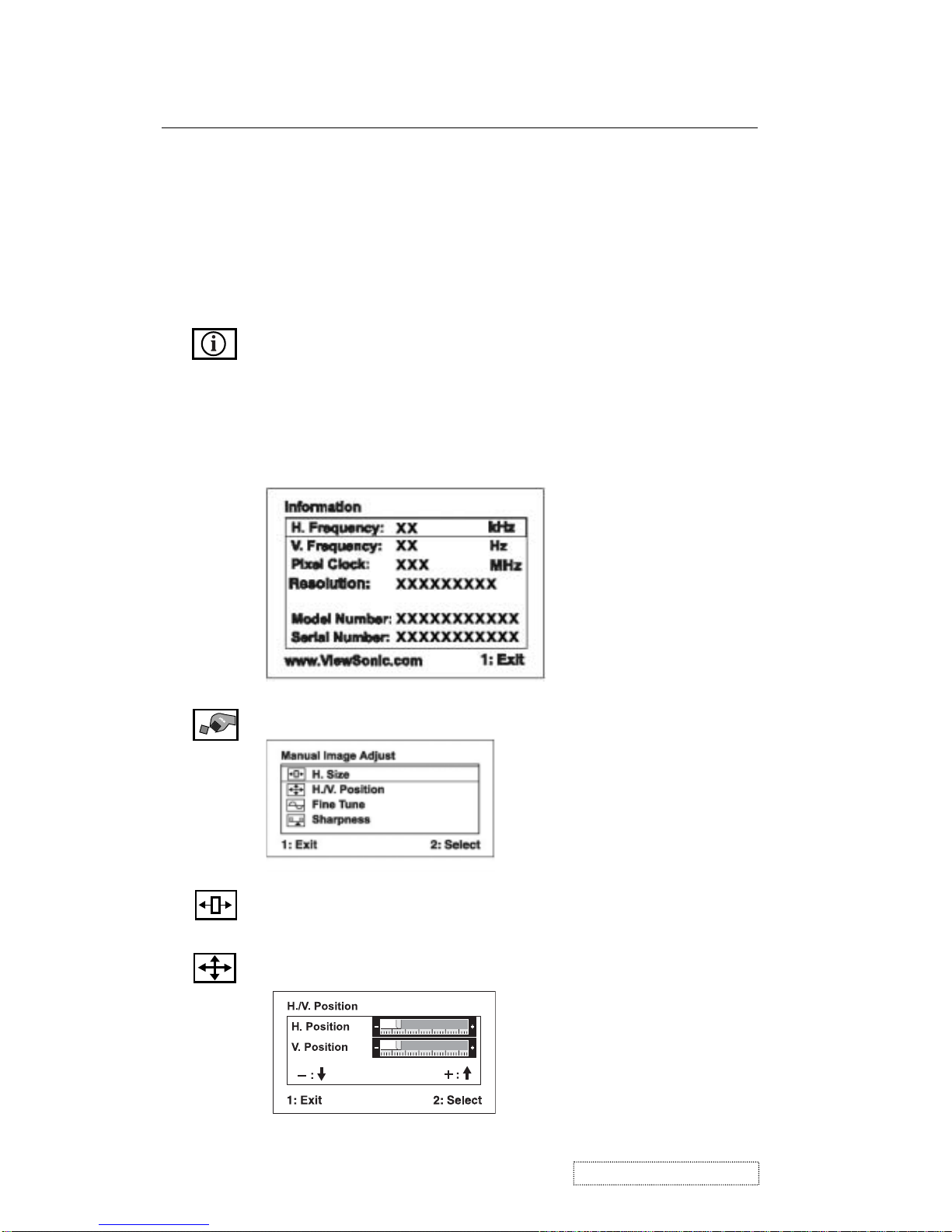
Information
displays the timing mode (video signal input)
coming from the graphics card in your computer, the LCD
model number, the serial number, and the ViewSonic website
URL. See your graphic card’s user guide for instructions on
changing the resolution and refresh rate (vertical frequency).
NOTE:
VESA 1280 x 1024 @ 60Hz (recommended) means
that the resolution is 1280 x 1024 and the refresh rate is 60
Hertz.
Manual Image Adjust Sub-menu
H. Size (Horizontal Size)
adjusts the width of the screen image.
H./V. Position (Horizontal/Vertical Position)
moves the screen
image left or right and up or down.
14
ViewSonic Corporation Confidential
-
Do Not Copy VP191b/s
Page 18
Fine Tune
sharpens the focus by aligning the text and/or graphic
characters.
NOTE:
Try Auto Image Adjust first.
Sharpness
adjusts the clarity and focus of the screen image.
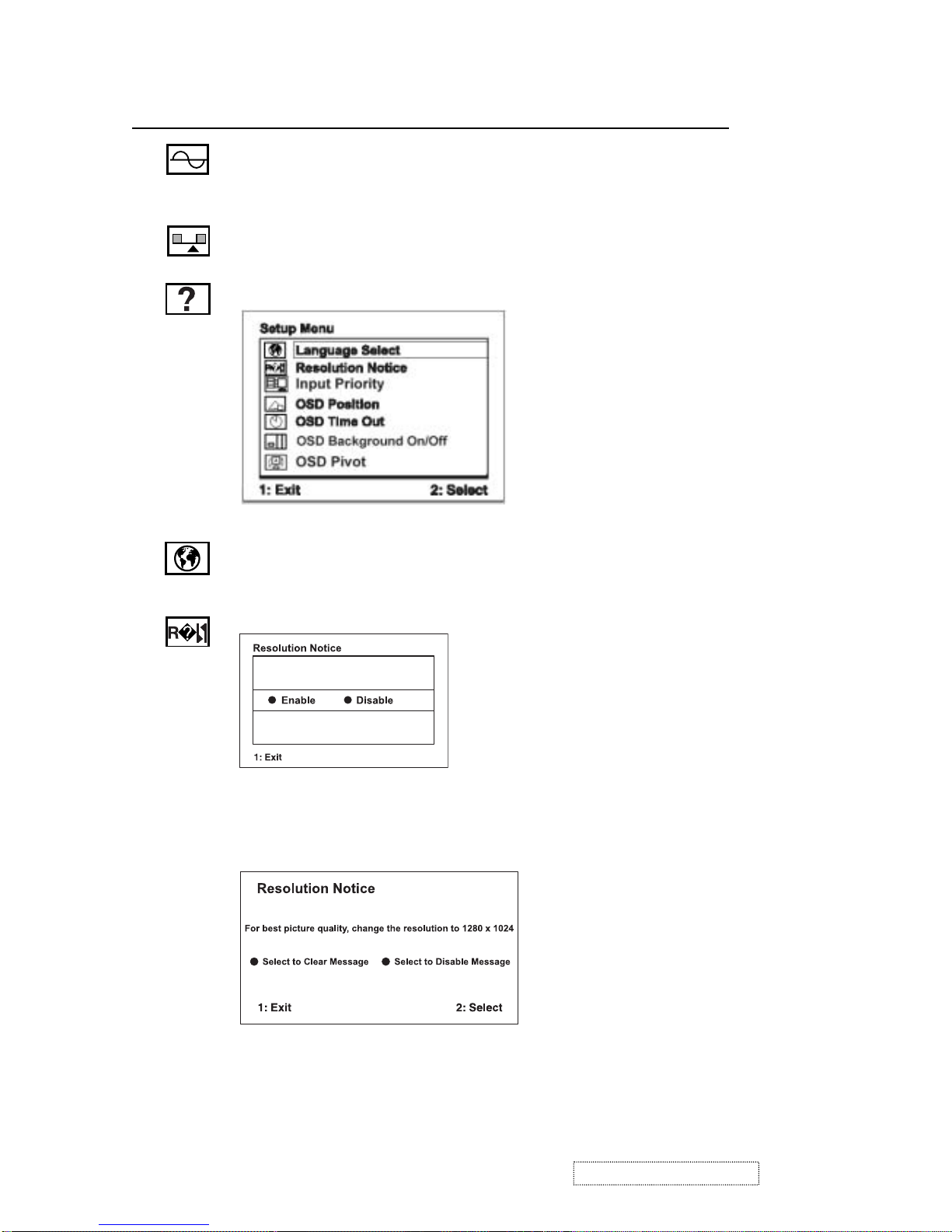
Setup menu displays the menu shown below:
Language
allows you to choose the language used in the menus
and control screens.
Control Explanation
Resolution Notice
allows you to enable or disable this notice.
If you enable the Resolution Notice shown above and your
computer is set at a resolution other than 1280 x 1024, the
following screen appears.
15
ViewSonic Corporation Confidential
-
Do Not Copy VP191b/s
Page 19
OSD Position
allows you to move the on-screen display menus
and control screens.
OSD Timeout
sets the length of time the on-screen display
screen is displayed. For example, with a “30 second” setting, if a
control is not pushed within 30 seconds, the display screen
disappears.
Control Explanation
Input Priority
If multiple computers will be connected to the display,
this function can be used to select which computer has priority
Depending on the selected Input Priority, the display will do a one
time detection for available inputs when first powered on.
For example: If the Input Priority setting is D-SUB=>D-SUB2=>DVI,
then the first priority will be given to D-SUB1 when the display turns
on. If there is no video signal on D-SUB1, then the next priority will be
given to D-SUB-2, etc… In the case of only one signal being present at
the three inputs, then the display will automatically detect and display
that signal.
The Input Priority setting can also be disabled. In this case, the input
will return to the last setting when the display is first turned on. The
user will need to control all the port settings manually under this
condition. Inputs can be switched quickly by pressing the "Up" arrow
button on the front panel controls.
Memory Recall
returns the adjustments back to factory settings
if the display is operating in a factory Preset Timing Mode listed
in the Specifications of this manual.
OSD Pivot
This function is used to rotate the OSD menu,
when the display is changed from Landscape to Portrait mode.
OSD Background
On/Off
allows you to turn the On-Screen Display
background On or Off.
16
ViewSonic Corporation Confidential
-
Do Not Copy VP191b/s
Page 20
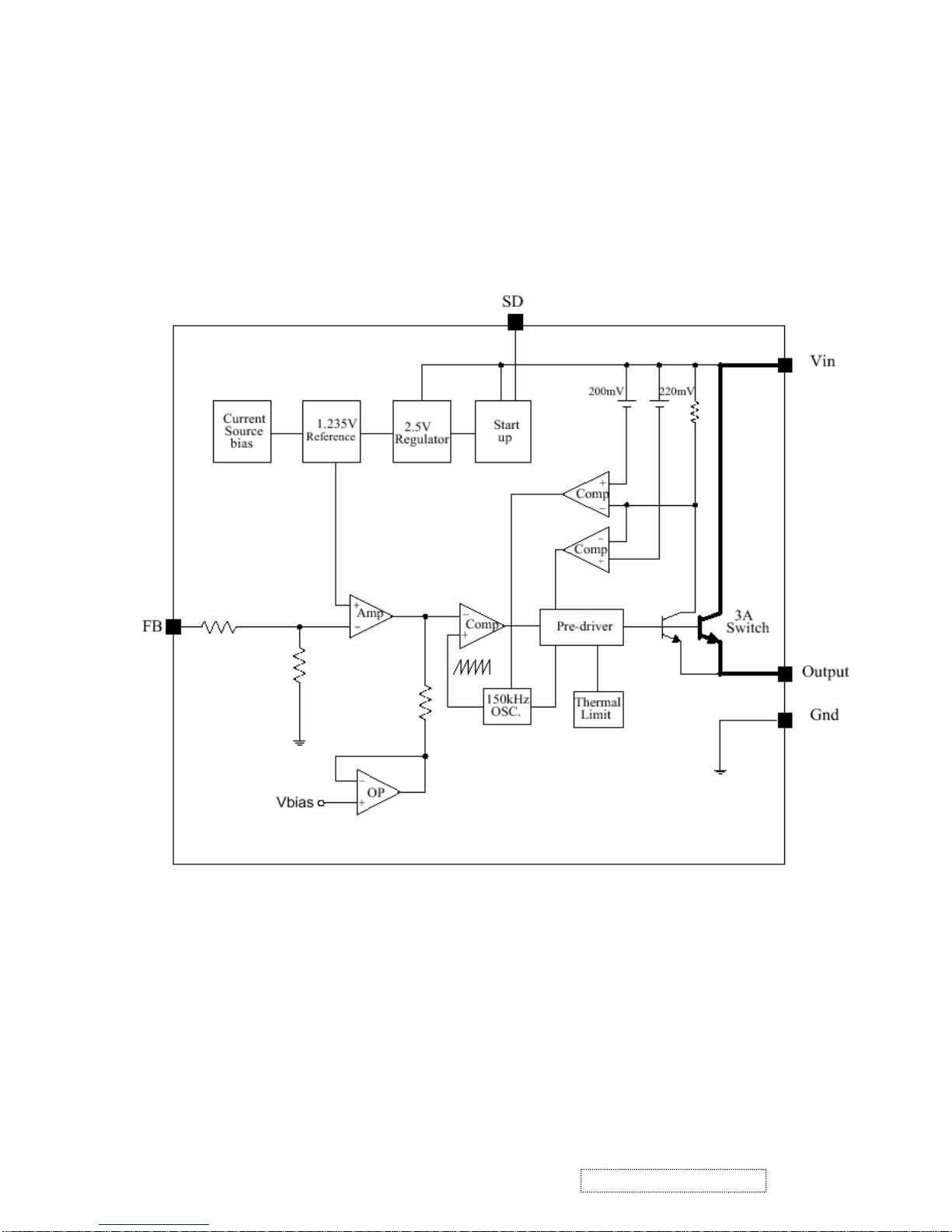
1. Power supply (DC/DC Converter)
The AP1501 is monolithic IC designed for M/B DC/DC converter, with the ability of driving a 3A load without any
additional transistor component.
The AP1501 operates at a switching frequency of 150 kHz and thus allows smaller-sized filter components than
would be needed with lower frequency switch regulator.
2. Flash Memory
The Pm39LV010R is a 1 Megabit, 3.3 Volt-only Flash Memory organized as 131,072 bytes of 8 bits each. This device is
designed to use a 3.0 Volt to 3.6 Volt power supply to perform in-system programming.
The 1 Megabit memory array is divided into thirty-two uniform blocks of 4 Kbytes each for data and/or code storage.
The block architecture allows users to flexibly make chip erase or block erase operation. The block erase feature allows a
particular block to be erased and reprogrammed without affecting the data in other blocks. After the device performs chip
4. Circuit Description
erase or block erase operation, it can be reprogrammed on a byte-by-byte basis.
17
ViewSonic Corporation Confidential
-
Do Not Copy VP191b/s
Page 21
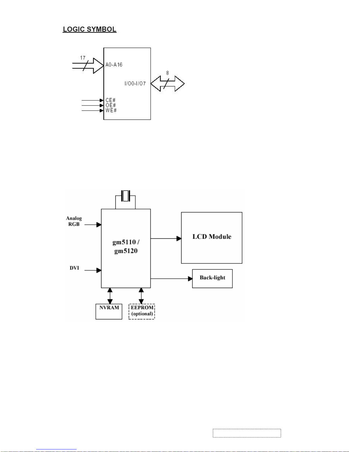
3. GM5120
The gm5110/20 is a graphic processing IC for Liquid Crystal Display (LCD) monitors at XGA/SXGA resolution. It
provides all key IC functions required for the highest quality LCD monitors. On-chip functions include a high-speed
triple-ADC and PLL, Ultra-Reliable DVI
TM
receiver, a high quality zoom and shrink scaling engine, an on-screen display
(OSD) controller, digital color controls and an on-chip microcontroller (OCM). With this level of integration, the
gm5110/20 devices simplify and reduce the cost of LCD monitors while maintaining a high-degree of flexibility and
quality.
gm5110/5120 System Design Example
4. LVDS (THC63LVDM8 3A)
The THC63LVDM83A transmitter converts 28 bits of CMOS/TTL data into LVDS (Low Voltage Differential Signaling)
data stream. A phase-locked transmit clock is transmitted in parallel with the data streams over a fifth LVDS link. The
HC63LVDM83A can be programmed for rising edge or falling edge clocks through a dedicated pin. The THC63LVDF84A
receiver converts the LVDS data streams back into 28 bits of CMOS/TTL data with falling edge clock. At a transmit clock
frequency of 85MHz, 24 bits of RGB data and 4 bits of LCD timing and control data (HSYNC, VSYNC, CNTL1, CNTL2)
are transmitted at a rate of 595 Mbps per LVDS data channel.
18
ViewSonic Corporation Confidential
-
Do Not Copy VP191b/s
Page 22
19 LCD Monitor
Color Video Signal & Pattern (or PC with SXGA resolution)
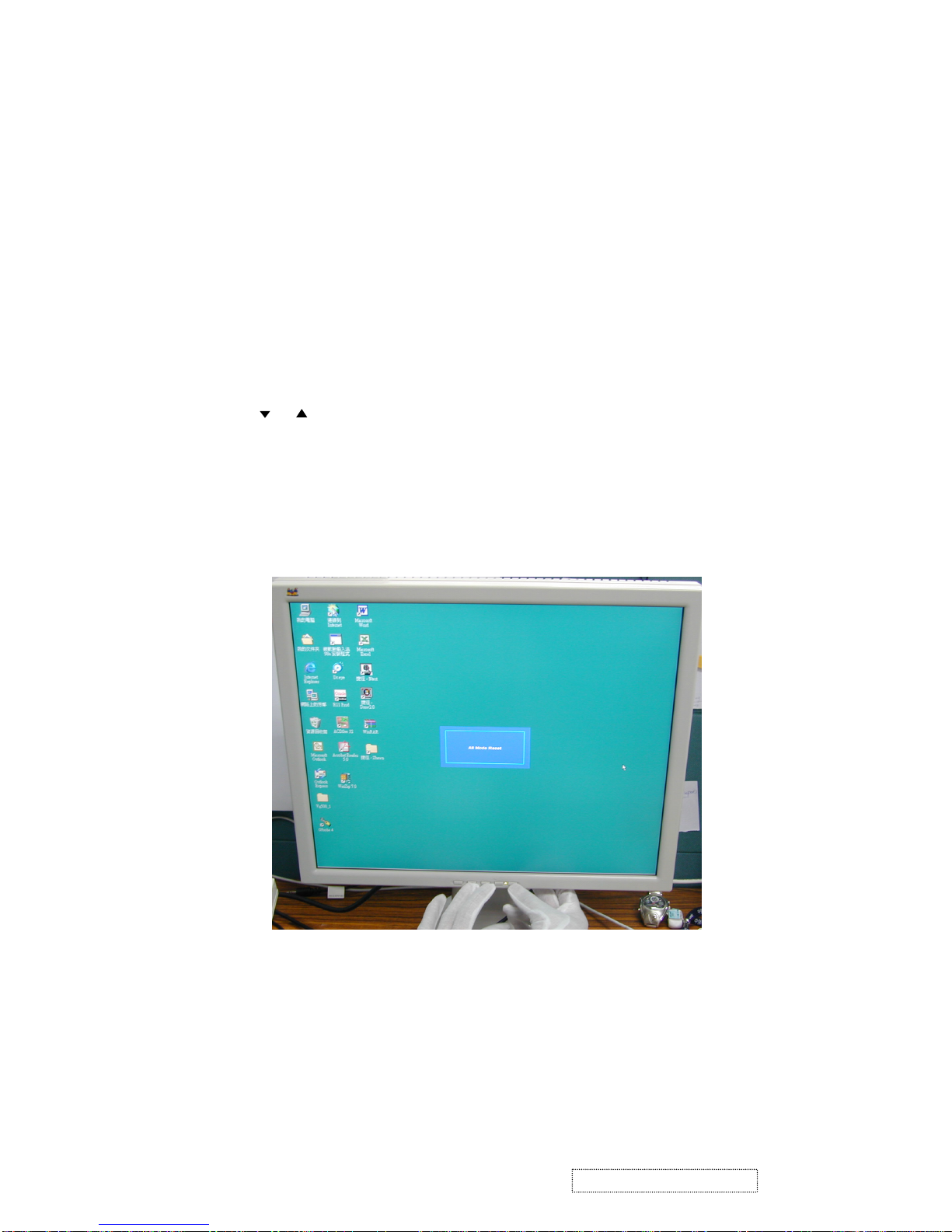
1). All Mode Reset:
Press , buttons simultaneously and Power on with signal, hold on for 3 seconds. Then the
screen will show All Mode Reset.
5. Adjusting Procedure
5-1 Function Test and Alignment Procedure
5-1-1 Product
5-1-2 Test Equipment
5-1-3 Hot Key
19
ViewSonic Corporation Confidential
-
Do Not Copy VP191b/s
Page 23
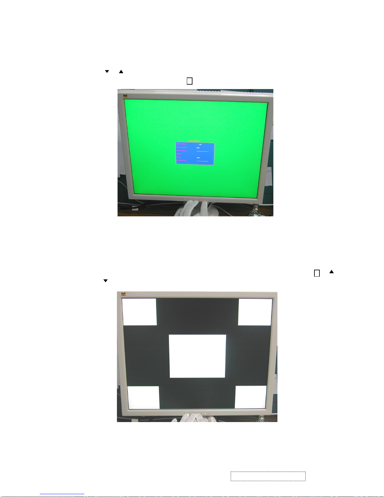
2). Burn In Mode:
Press , buttons simultaneously and Power on without signal, hold on for 3 seconds. Then the
screen will show Burn In Mode. Press button, you can find the information about this monitor.
3). White Balance:
Set the screen on 640*480@60Hz resolution pure black and white pattern, no other color. Press ,
and simultaneously.
1
1
20
ViewSonic Corporation Confidential
-
Do Not Copy VP191b/s
Page 24
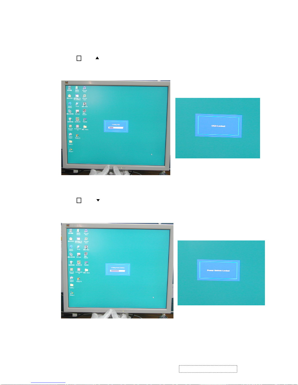
4). OSD Lock :
Press and buttons simultaneously for 10 seconds, and the OSD will lock. Repeat the action, and
the OSD will unlock.
5). Power Lock :
Press and buttons simultaneously for 10 seconds, and the Power will lock. Repeat the action,
and the Power will unlock.
1
1
21
ViewSonic Corporation Confidential
-
Do Not Copy VP191b/s
Page 25
6). Contrast and Brightness Recall :
Press and buttons simultaneously, and the contrast and brightness will restore the factory
defaults.
7). Test Mode(720*400)/Graphic Mode (640*400) exchange :
Press and buttons simultaneously.
Before function test and alignment, each LCD Monitor should be run-in and warmed-up for at least 30
minutes with the following conditions:
a). In room temperature,
b). With full-white screen, R.G.B. Black
c). With cycled display modes,
640*480 (H=43.27kHz, V=85Hz)
800*600 (H=53.7kHz, V=85Hz)
1024*768 (H=68.67kHz, V=85Hz)
1280*1024 (H=79.97kHz, V=75Hz)
1
2
5-1-4 Test Condition
22
ViewSonic Corporation Confidential
-
Do Not Copy VP191b/s
Page 26

640 x 350 @ 70Hz, 31.5kHz
640 x 480 @ 60Hz, 31.5kHz
640 x 480 @ 67Hz, 35.0kHz
640 x 480 @ 75Hz, 37.5kHz
640 x 480 @ 72Hz, 37.9kHz
640 x 480 @ 85Hz, 43.27kHz
720 x 400 @ 70Hz, 31.5kHz
800 x 600 @ 56Hz, 35.1kHz
800 x 600 @ 60Hz, 37.9kHz
800 x 600 @ 75Hz, 46.9kHz
800 x 600 @ 72Hz, 48.1kHz
800 x 600 @ 85Hz, 53.7kHz
832 x 624 @ 75Hz, 49.7kHz
1024 x 768 @ 60Hz, 48.4kHz
1024 x 768 @ 70Hz, 56.5kHz
1024 x 768 @ 72Hz, 58.1kHz
1024 x 768 @ 75Hz, 60.0kHz
1024 x 768 @ 85Hz, 68.67kHz
1152 x 870 @ 75Hz, 68.6kHz,
1280 x 1024 @ 60Hz, 63.4kHz
1280 x 1024 @ 75Hz, 79.97kHz
1280 x 720 @ 60Hz, 45kHz
Analog :
640 x 350 @ 70Hz, 31.5kHz
640 x 400 @ 70Hz, 31.5kHz
640 x 480 @ 60Hz, 31.5kHz
640 x 480 @ 75Hz, 37.5kHz
640 x 480 @ 72Hz, 37.9kHz
640 x 480 @ 85Hz, 43.27kHz
720 x 400 @ 70Hz, 31.5kHz
800 x 600 @ 56Hz, 35.1kHz
800 x 600 @ 60Hz, 37.9kHz
800 x 600 @ 75Hz, 46.9kHz
800 x 600 @ 72Hz, 48.1kHz
800 x 600 @ 85Hz, 53.7kHz
1024 x 768 @ 60Hz, 48.4kHz
1024 x 768 @ 70Hz, 56.5kHz
1024 x 768 @ 72Hz, 58.1kHz
1024 x 768 @ 75Hz, 60.0kHz
1024 x 768 @ 85Hz, 68.67kHz
1152 x 870 @ 75Hz, 68.6kHz,
1280 x 1024 @ 60Hz, 63.4kHz
1280 x 1024 @ 75HZ,79.97khz
1280 x 720 @ 60Hz, 45kHz
Digital :
5-1-5 Test Display Modes & Pattern
. Compatible Modes
23
ViewSonic Corporation Confidential
-
Do Not Copy VP191b/s
Page 27

Fine Line Morie Pattern (Figure 1) Gray Scale Pattern (Figure 2)
Horizontal & Vertical Thickness Pattern R. Color Pattern (Figure 4)
(Figure 3)
metI tnetnoCtseT nrettaP noitacificepS krameR
1
&ycneuqerF
gnikcarT
erioMeniLeniF.esionyvawlausivetanimilE1erugiF
2ssenthgirB/tsartnoCelacSyarG61
ebdluohsslevelyarg61
.elbahsiugnitsid
2erugiF
3yradnuoB
&latnoziroH
ssenkcihTlacitreV
dluohsoedivfonoitisop.treVdna.zroH
neercsehtnihtiwebotelbatsujdaeb
.emarf
3erugiF
4
roloC,B,G,R
ecnamrofreP
roloCB.G.R
seitisnetnI
dluohsroloc,B,G,RhcaefotsartnoC
.lamroneb
erugiF
6,5,4
5
ytimrofinUneercS
rekcilF&
etihWlluF.cepsehthtiwtnailpmocebdluohS7erugF
6eniL/lexiPdaeD
neercSetihW
neercSkraD
ebdluohsslexipdaedfosrebmunehT
.cepsehthtiwtnailpmoc
8,7erugiF
7ecnalaBetihW
kcalB&etihW
nrettaP
etihwerupehtevahtsumneercsehT
.rolocrehtoon,nrettapkcalbdna
9erugiF
24
ViewSonic Corporation Confidential
-
Do Not Copy VP191b/s
. Funcation Test Display Patterm
Page 28

G. Color Pattern (Figure 5) B. Color Pattern (Figure 6)
Full White Pattern (Figure 7) Dark Screen Pattern (Figure 8)
Black-White Pattern (Figure 9)
25
ViewSonic Corporation Confidential
-
Do Not Copy VP191b/s
Page 29

You should do All Mode Reset (Refer to Chapter 6-3) first. This action will allow you to erase all end-
users settings and restore the factory defaults.
Please select and enter Auto Image Adjust function on Main Menu to see if it is workable. The Auto
Image Adjust function is aimed to offer a better screen quality by built-in ASIC. For optimum screen
quality, the user has to adjust each function manually.
Test Pattern: Burn In Mode (Refer to Chapter 6-3)
- Make sure the F/W is the latest version.
- Make sure the S/N is the same as the Spec. label.
- Make sure the model name is correct.
Test Signal: 1280*1024@60Hz
Test Pattern: Line Moire Pattern
- Check and see if the image has noise and focus performs well eliminate visual line bar.
- If not, readjust by the following steps :
(a) Select and enter Fine Tune function on Manual Image Adjust to adjust
the image to eliminate visual wavy noise.
(b) Then, select and enter Sharpness function to adjust the clarity and focus
of the screen image.
Test Signal : 1280*1024@60Hz
Test Pattern : Horizontal & Vertical Line Thickness Pattern
- Check and see if the image boundary is within the screen frame.
- If not, readjust by the following steps :
(a) Select and enter Manual Image Adjust function on OSD Main Menu.
(b) Then, select and enter Horizontal Size or Horizontal/Vertical Position
function to adjust the video boundary to be full scanned and within screen frame.
Test Signal : 1280*1024@60Hz
Test Pattern: Full White and Black Pattern
- Refer to Chapter 6-3
26
ViewSonic Corporation Confidential
-
Do Not Copy VP191b/s
5-1-6 Function Test and Alignment Procedure
.
All Modes Reset
. Auto Image Adjust
. Firmware and DDC
.
Fine Tune and Sharpness
.
Boundary
.
White Balance
Page 30

Test Signal: 1280*1024@60Hz
Test Pattern: R,G,B Color Intensities Pattern and 16 Gray Scale Pattern
- Check and see if each color is normal and distinguishable.
- If not, please return the unit to repair area.
Test Signal: 1280*1024@60Hz
Test Pattern: Full White Pattern
- Check and see if it is in normal condition.
Test Signal: 1280*1024@60Hz
Test Pattern: Dark and White Screen Pattern
- Check and see if there are dead pixels on LCD panel with shadow gauge and filter film.
- The total numbers and distance of dead pixels should be compliant with the spec.
Test Signal:
Analog : 640*350@70Hz; 640*480@60/67/72/75/85Hz;
720*400@70Hz; 800*600@56/60/72/75/85Hz;
832*624@75Hz,1024*768@60/70/72/75/85Hz;
1152*870@75Hz, 1280*720@60Hz, 1280*1024@60/75Hz
Digital : 640*350@70Hz; 640*450@75Hz; 640*480@60/72/75Hz;
720*400@70Hz; 800*600@56/60/72/75/85Hz;
1024*768@60/70/72/75/85Hz; 1152*870@75Hz,
1280*720@60Hz, 1280*1024@60/75Hz
- Normally when the primary mode 1280*1024@75Hz is well adjusted and
compliant with the specification, the secondary display modes will also be
compliant with the spec. It is still necessary to check with the general test pattern
to make sure every secondary is compliant with the specification.
After final QC step, we have to erase all saved changes again and restore the factory
defaults. You should do All Mode Reset (Refer to Chapter 6-3) again.
Turn off monitor by pressing Power button, and turn off the Switch that is back of the monitor.
27
ViewSonic Corporation Confidential
-
Do Not Copy VP191b/s
. R,G,B, Color Contrast
. Screen Uniformity and Flicker
.
Dead Pixel and Line
. Check for Secondary Display Modes
. All Modes Reset
. Power Off Monitor
Page 31

- VP191 Series Monitor
- Fixture for Firmware Upgrade
- Power Adapter (P/N : 47.58201.001) *1 for Fixture
- VGA Cable (P/N : 42.59901.008) *1
- PC (Personal Computer)
- LTP Cable (P/N : 42.59906.001) *1
- Firmware Upgrade Program
- One additional monitor for checking the program execution
Printer Port
PC
VP191 Monitor
VGA Cable (P/N: 42.59901.008)
Fixture
28
ViewSonic Corporation Confidential
-
Do Not Copy VP191b/s
5-2 Firmware Upgrade Procedure
5-2-1 Equipment Needed
Page 32

Power Adapter for Fixture
(P/N: 47.58201.001)
LTP Cable (P/N: 42.59906.001)
1. Connect P2 of Fixture with printer port of PC by LTP Cable.
2. Connect P1 of Fixture with VP191 Monitor by VGA Cable.
3. Plug Power Adapter to Fixture.
4. Connect Power Cord to VP191 Monitor, and turn on the Power Switch.
5. Connect PC to the additional monitor.
P2 : to LTP Cable
JP1 : to Power
Adapter
P1 : to VGA Cable
VGA Port
Connect to Power Cord
Turn on the Power Switch
29
ViewSonic Corporation Confidential
-
Do Not Copy VP191b/s
5-2-2 Set-up Procedure
Page 33

6. Install GProbe Program by selecting and clicking Gprobe icon.
Press Yes or Next buttons until the program is finished.
30
ViewSonic Corporation Confidential
-
Do Not Copy VP191b/s
Page 34

31
ViewSonic Corporation Confidential
-
Do Not Copy VP191b/s
Page 35

32
ViewSonic Corporation Confidential
-
Do Not Copy VP191b/s
Page 36

1. Save these three files <bdisp.txt>, <p204_205.bin> and <vp191_v3_20a.bin> in the computer.
2. Open <bdisp.txt> file.
Key in the path where you save the driver <p204_205.bin> and firmware <vp191_v3_20a.bin>.
33
ViewSonic Corporation Confidential
-
Do Not Copy VP191b/s
5-2-3 Firmware Upgrade Procedure
Page 37

3. Execute Gprobe program.
4. Key in batch c:\VP191\bdisp.txt after GProbe :>, then press Enter key to
begin programming automatically.
the path is where you save <bdisp.txt> file
34
ViewSonic Corporation Confidential
-
Do Not Copy VP191b/s
Page 38

5. The successful picture is as follows :
6. Enter Burn In Mode (refer to Chapter 6-3), and you could find that Serial Number disappears.
35
ViewSonic Corporation Confidential
-
Do Not Copy VP191b/s
Page 39

7. Turn off the power switch of the rear cover of VP191, and turn it on again.
Then enter Burn In Mode, and Serial Number will appear. Check if the version of BIOS is correct.
Power Switch
8.Connect the signal, and the monitor will slant to red color. Refer to Chapter 6-3 to
do White Balance.
9.At last, do All Mode Reset.
36
ViewSonic Corporation Confidential
-
Do Not Copy VP191b/s
Page 40

-
VP191 Series Monitor
-
Fixture(V3) for DDC Key In (JP3 must be closed)
-
RS232 Cable (P/N : 42.55907.001) *1
-
VGA Cable (P/N : 42.59901.008) *2
-
DVI-DVI Cable *1
-
PC (Personal Computer)
-
Power Adapter (P/N: 47.56001.501) *1 for Fixture
-
DDC Key In Program
-
One additional monitor for checking the program execution
COM1 : to
RS232 Cable
PC
VP191 Monitor
VGA Cable (P/N: 42.59901.008)
Fixture
RS-232 Cable (P/N: 42.55907.001)
37
ViewSonic Corporation Confidential
-
Do Not Copy VP191b/s
5-3 DDK Key In Procedure
5-3-1 Equipment Needed
Page 41

DVI-DVI Cable
1.Connect P2 and P4 of Fixture with VGA ports of VP191 by two VGA Cables.
2.Connect P3 of Fixture with DVI port of VP191 by DVI-DVI Cable.
3.Connect P1 of Fixture with COM1 of PC by RS232 Cable.
4.Plug Power Adapter to Fixture.
5.Connect Power Cord to VP191 Monitor, and turn on the Power Switch.
6.Connect PC to the additional monitor.
P3 : to DVI-DVI
Cable
JP1 : to
Power
Adapter
P1 : to RS232 Cable
P2 & P4 : to VGA
Cables
Power Adapter for Fixture
(P/N: 47.56001.501)
VGA Port
Connect to
Power Cord
Turn on the Power Switch
DVI Port
38
ViewSonic Corporation Confidential
-
Do Not Copy VP191b/s
5-3-2 Set-Up Procedure
Page 42

1. Select and execute DDC Key In program.
2. Key in the serial number and press Enter key.
39
ViewSonic Corporation Confidential
-
Do Not Copy VP191b/s
5-3-3 DDC Key In Procedure
Page 43

3. The successful picture is as follows :
(There are checksum values appearing when VGA and DVI success.)
4. Press ~ button (Shift+ ) to check DDC CheckSum is correct or not.
`
40
ViewSonic Corporation Confidential
-
Do Not Copy VP191b/s
Page 44

5. Enter Burn In Mode (refer to Chapter 6-3). Turn off the power switch of the rear cover of VP191,
and turn it on again. Then enter Burn In Mode again and Information of OSD Main Menu.
Check if the information is correct.
41
ViewSonic Corporation Confidential
-
Do Not Copy VP191b/s
Page 45

- VP191 Monitor
- Philips Screw Driver #101 and #107
- Electronic Hex Nut M5mm
-PC(Personal Computer) with SXGA resolution / Pattern Generator
Start
Power-on
Power LED ok ?
A. Power Circuit
Troubleshooting
Ye s
No
Is display
performance ok ?
Ye s
No
Is function
adjustment ok ?
No
End
B. Performance
Troubleshooting
C. Control Function
Troubleshooting
Ye s
This chapter provides technicians and people who have an electronic background a pri-
mary description about maintaining the product. Moreover, you can get the appropriate opera-
tion to solve some complicated problems of component repairing and professional problems.
42
ViewSonic Corporation Confidential
-
Do Not Copy VP191b/s
6. Trouble Shooting Flow Chart
6-1 Equipment Needed
6-2 Main Procedure
Page 46

Start
Change
Main Board
Change
Power
Board
Ye s
Ye s
No
End
Start
Ye s
No
Change
LCD Panel
Change
Main Board
Is screen white ?
Ye s
Ye s
No
Ye s
No
Change
LCD Panel
Change
Main Board
Abnormal Color ?
Ye s
Ye s
No
Ye s
Replug/Change
FPC Cable
No
1
Ye s
No
Change
LCD Panel
Change
Main Board
Is screen black ?
Ye s
Ye s
No
Ye s
Change
Inverter Board
No
43
ViewSonic Corporation Confidential
-
Do Not Copy VP191b/s
6-2-1 Power Circuit Troubleshooting
6-2-2 Performance Troubleshooting
Page 47

Notice :
1. Make sure VGA cable connect to PC directly and not through a Data transfer or Distribution......After this action if
Ghost image disappear, go to Yes; else, go to No.
2. Check the compatibility on the computer. If it is compatibility problem, feedback the information to ViewSonic, else, go
to No.
Ye s
Ye s
No
No
Ye s
Change
Main Board
Change
Main Board
Change
VG A Cab le
Change
LCD Panel
Is screen scrolling ?
Is screen flickering ?
Ye s
Ye s
Ye s
Ye s
No
No
End
Ye s
No
No
Ye s
Change
LCD Panel
Change
Inverter Board
Is LCD line defective ?
Bad Uniformity ?
Ye s
No
Ye s
Change
Main Board
Have line bar or noise?
Ye s
Ye s
No
1
Ye s
No
Ye s
Ghost image ?
No
Change
LCD Panel
Ye s
Refer to
Notice 1
No
No
Change
Main Board
Adjust Fine Tune
Sharpness or Auto
Adjustment
Adjust Fine Tune
Sharpness or
Auto Adjustment
Refer to
Notice 2
No
Ye s
Ye s
Ye s
44
ViewSonic Corporation Confidential
-
Do Not Copy VP191b/s
Page 48

Ye s
Start
No
Change
Main Board
Change
Control Board
Ye s
End
45
ViewSonic Corporation Confidential
-
Do Not Copy VP191b/s
6-2-3 Control Function Troubleshooting
Page 49

Rev: 1b
Item ECR/ECN ViewSonic P/N Ref. P/N Location Q'ty
1
Accessories:
OPEN FRAME IN:100-240V OUT:12V/4.16A "TIGER A-AD-0114-0242 44.61103.002 ADAPTER 1
2 PCBA CTRL BD FOR VP171 B-CB-0206-0158 80.61102.001 CONTROL BOARD 1
3 PCBA INVERTER PLCD0819402;EMAX FOR 19" FJUI B-SB-0221-0601 44.59501.001 INVERTER 1
4 OPEN FRAME IN:100-240V OUT:12V/4.16A"LSE"(N B-PS-0204-0057 44.61103.003 ADAPTER 1
PCBA MAIN BD FOR VP191 FUJITSU-11A Removed 10/15/04 B-MB-0201-0855 80.61201.003 MAIN BOARD 1
PCBA MAIN BOARD FOR VP191 FUJ-11AA Added 10/15/04 B-00000332 80.61201.005 MAIN BOARD 1
6 ASSY HINGE CAP PC+ABS-VS08 VP191b M-CV-0830-2432 75.61202.002 HINGE CAP 1
7 BASE COVER PC+ABS-VS08 VP191b M-CV-0830-2430 51.61209.002 BASE COVER 1
8 FRONT ARM PC+ABS-VS08 VP191b M-MS-0808-7823 51.61207.002 FRONT ARM 1
9 FRONT COVER PC+ABS-VS08A VP191b C-FP-0301-0375 51.61201.002 FRONT COVER 1
10 HINGE CAP-1 PC+ABS-VS08 VP191b M-CV-0830-2427 51.61204.002 HINGE CAP-1 1
11 HINGE CAP-2 PC+ABS-VSVS08 VP191b M-CV-0830-2428 51.61205.002 HINGE CAP-2 1
12 HINGE CAP-3 PC+ABS-VSVS08 VP191b M-CV-0830-2429 51.61206.002 HINGE CAP-3 1
13 HINGE CAP-4 PC+ABS-VS08 VP191b M-CV-0830-2431 51.61212.002 HINGE CAP-4 1
14 OVAL CAP PC+ABS-VS08 VP191b M-CV-0830-2426 51.61203.002 OVAL CAP 1
15 REAR ARM PC+ABS-VS08 VP191b M-MS-0808-7824 51.61208.002 REAR ARM 1
16 REAR COVER PC+ABS-VS08 VP191b C-BC-0302-0496 51.61202.002 REAR COVER 1
17 CABLE DVI-D 1800mm COLOR:CS-VS08 A-VC-0101-0262 42.59902.012 DVI-D CABLE 1
18 CABLE VGA 15P 1800mm 2-CORE COLOR:CS-VS08 A-VC-0101-0261 42.59901.003 VGA CABLE 1
19 W.A. 10/6P UL1007 #24 50mm VP191(INV) M-WR-0828-0716 42.61202.001 INVERTER WIRE 1
20 W.A. 30P UL20276 #28 250mm VP191 M-WR-0828-0725 42.61201.001 WIRE 1
21 W.A. 3P UL1007 #18 50mm VP191(INLET) M-WR-0828-0719 42.61205.001 INLET WIRE 1
22 W.A. 4P UL1007 #18 VP191(SWT) M-WR-0828-0718 42.61204.001 SWITCH WIRE 1
23 W.A. 4P UL1007 #24 250mm VP191(POWER) M-WR-0828-0717 42.61203.001 POWER WIRE 1
24 LABEL BAR CODE 50*25mm VP191 M-LB-0813-0781 35.61203.001 BARCODE LABEL 1
25 LABEL SPEC 120*50mm VP191b M-LB-0813-0783 35.61201.002 SPEC LABEL 1
26 USER GUIDE+CD(FUJITSU PANEL) A-UG-0107-0532 36.61202.002 USER GUIDE 1
TFT LCD 19" FUJITSU FLC48SXC8V-11A SXGA Removed 10/15/04 M-LCD-0826-0227 48.61201.001 LCD PANEL 1
TFT LCD 19" FUJITSU FLC48SXC8V-11AA SXGA Added 10/15/04 E-00000333 48.61201.002 LCD PANEL 1
28 MYLAR ADHESIVE t=0.3mm VP191 M-MS-0808-7797 51.61216.001 MYLAR 1
29 EMI Tape (80560) 30*50mm M-MS-0808-7798 41.53615.001 EMI TAPE 2
30 EMI GASKET UGT-7-0.5-8mm M-MS-0808-9541 41.54002.002 EMI GASKET 2
31 EMI Tape (80560) 25*30mm M-MS-0808-7799 41.54612.001 EMI TAPE 6
32 BIRD LOGO AL E015-004 "ViewSonic" M-MS-0808-7800 35.61202.001 LOGO 1
33 CARTON AB-18 490*265*440 VP191b P-BX-0601-0801 55.61201.002 CARTON 1
34 CUSHION R EPS VP191 P-FM-0602-0579 56.61201.001 RIGHT CUSHION 1
35 CUSHION L EPS VP191 P-FM-0602-0580 56.61202.001 LEFT CUSHION 1
36 CLIP NYLON-VS08 VP191b PL-CL-0710-0033 51.61213.002 CLIP 3
37 LED LENS PMMA VP191 M-MS-0808-9539 51.61211.001 LED LENS 1
38 NAMEPLATE ELLIPSE VIEWSONIC M-MS-0808-8299 51.58711.002 NAMEPLATE 1
39 RUBBER PAD 27d*2t VP191 PL-PD-0714-0091 52.61201.001 RUBBER PAD 4
40 SELECT BUTTON PC+ABS-VS08A VP191b PL-BT-0706-0134 51.61210.002 SELECT BUTTON 1
41 WEAR PLATE (FRONT) VP191 M-MS-0808-7795 51.61214.001 WEAR PLATE 1
42 WEAR PLATE (REAR) VP191 M-MS-0808-7796 51.61215.001 WEAR PLATE 1
Rev: 1b
Item ECR/ECN ViewSonic P/N Ref. P/N Location Q'ty
1
Accessories:
CABLE POWER CORD 1830mm SP30+IS14 A-PC-0106-0272 42.50115.001 1
Rev: 1b
Item ECR/ECN ViewSonic P/N Ref. P/N Location Q'ty
1
Accessories:
CABLE POWER CORD 1830mm SP30+IS14 A-PC-0106-0272 42.50115.001 1
Rev: 1b
Item ECR/ECN ViewSonic P/N Ref. P/N Location Q'ty
1
Accessories:
CABLE POWER CORD 1.8M±0.1M (CHINA) A-PC-0106-0187 42.50126.001 POWER CORD 1
2 WARRANTY CARD S. CHINESE SECOND VERSION VIEWSONIC M-MS-0808-8773 36.58307.002 WARRANTY 1
3 WARRANTY STICKER S. CHINESE M-LB-0813-0737 36.58308.001 WARRANTY 1
4 SHIPPING WARRANTY STICKER S. CHINESE VIEWSONIC M-LB-0813-0739 36.58309.001 WARRANTY 1
5
Packing Material:
PE BAG LDPE 820*850*0.05t VP191/191b(FOR CARTON)
M-MS-0808-8794
51.61219.001
PE BAG
1
Rev: 1b
Item ECR/ECN ViewSonic P/N Ref. P/N Location Q'ty
1
Accessories:
CABLE POWER CORD 1830mm SP30+IS14 A-PC-0106-0272 42.50115.001 1
Rev: 1b
Item ECR/ECN ViewSonic P/N Ref. P/N Location Q'ty
1
Accessories:
CABLE POWER CORD 1830mm SP-023+IS14 EUR. A-PC-0106-0271 42.50112.001 1
5
RECOMMENDED SPARE PARTS LIST (VP191b-1)
ViewSonic Model Number: VLCDS25973
Description
Plastics:
ViewSonic Model Number: VLCDS25973-1M
27
Miscellaneous:
Packing Material:
PC Board Assembly:
Documentation:
Cables:
Electronic
Components:
Cabinets:
ViewSonic Model Number: VLCDS25973-1P
Description
Description
Documentation:
ViewSonic Model Number: VLCDS25973-1G
Description
Description
ViewSonic Model Number: VLCDS25973-1A
Description
ViewSonic Model Number: VLCDS25973-1E
7. Recommended Spare Parts List
46
ViewSonic Corporation Confidential
-
Do Not Copy VP191b/s
Page 50

Rev: 1b
Item ECR/ECN ViewSonic P/N Ref. P/N Location Q'ty
1
Accessories:
OPEN FRAME IN:100-240V OUT:12V/4.16A "TIGER A-AD-0114-0242 44.61103.002 ADAPTER 1
2 OPEN FRAME IN:100-240V OUT:12V/4.16A"LSE"(N B-PS-0204-0057 44.61103.003 ADAPTER 1
3 PCBA INVERTER PLCD0819402;EMAX FOR 19" FJUI B-SB-0221-0601 44.59501.001 INVERTER 1
4 PCBA CTRL BD FOR VP171 B-CB-0206-0158 80.61102.001 CONTROL BOARD 1
PCBA MAIN BD FOR VP191 FUJITSU-11A Removed 10/15/04 B-MB-0201-0855 80.61201.003 MAIN BOARD 1
PCBA MAIN BOARD FOR VP191 FUJ-11AA Added 10/15/04 B-00000332 80.61201.005 MAIN BOARD 1
6 REAR COVER PC+ABS-VS06A VP191s C-BC-0302-0509 51.61202.003 REAR COVER 1
7 OVAL CAP PC+ABS-VS06A VP191s M-CV-0830-2452 51.61203.003 OVAL CAP 1
8 HINGE CAP-1 PC+ABS-VS06 VP191s M-CV-0830-0297 51.61204.003 HINGE CAP-1 1
9 HINGE CAP-2 PC+ABS-VS06 VP191s M-CV-0830-0298 51.61205.003 HINGE CAP-2 1
10 HINGE CAP-3 PC+ABS-VS06 VP191s M-CV-0830-2453 51.61206.003 HINGE CAP-3 1
11 FRONT ARM PC+ABS-VS06 VP191s M-MS-0808-8751 51.61207.003 FRONT ARM 1
12 REAR ARM PC+ABS-VS06 VP191s M-MS-0808-8752 51.61208.003 REAR ARM 1
13 BASE COVER PC+ABS-VS06 VP191s M-CV-0830-2454 51.61209.003 BASE COVER 1
14 HINGE CAP-4 PC+ABS-VS06 VP191s M-CV-0830-2455 51.61212.003 HINGE CAP-4 1
15 ASSY HINGE CAP CS-VS06 VP191s M-CV-0830-2457 75.61202.003 HINGE CAP 1
16 FRONT COVER PC+ABS VS-07A VP191s C-FP-0301-0355 51.61201.003 FRONT COVER 1
17 CABLE VGA 15P 1800mm 2-CORE COLOR:CS-VS08 A-VC-0101-0261 42.59901.003 VGA CABLE 1
18 CABLE DVI-D 1800mm COLOR:CS-VS08 A-VC-0101-0262 42.59902.012 DVI-D CABLE 1
19 W.A. 30P UL20276 #28 250mm VP191 M-WR-0828-0725 42.61201.001 WIRE 1
20 W.A. 10/6P UL1007 #24 50mm VP191(INV) M-WR-0828-0716 42.61202.001 INVERTER WIRE 1
21 W.A. 4P UL1007 #24 250mm VP191(POWER) M-WR-0828-0717 42.61203.001 POWER WIRE 1
22 W.A. 4P UL1007 #18 VP191(SWT) M-WR-0828-0718 42.61204.001 SWITCH WIRE 1
23 W.A. 3P UL1007 #18 50mm VP191(INLET) M-WR-0828-0719 42.61205.001 INLET WIRE 1
24 USER GUIDE+CD,VP191s(FUJITSU-11 PANEL) A-CD-VP191S 36.61201.004 USER GUIDE 1
25 LABEL SPEC 120*50mm VP191s M-LB-0813-0835 35.61201.003 SPEC LABEL 1
26 LABEL BAR CODE 50*25mm VP191 M-LB-0813-0781 35.61203.001 BARCODE LABEL 1
TFT LCD 19" FUJITSU FLC48SXC8V-11A SXGA Removed 10/15/04 M-LCD-0826-0227 48.61201.001 LCD PANEL 1
TFT LCD 19" FUJITSU FLC48SXC8V-11AA SXGA Added 10/15/04 E-00000333 48.61201.002 LCD PANEL 1
28 MYLAR ADHESIVE t=0.3mm VP191 M-MS-0808-7797 51.61216.001 MYLAR 1
29 EMI Tape (80560) 30*50mm M-MS-0808-7798 41.53615.001 EMI TAPE 2
30 EMI GASKET UGT-7-0.5-8mm M-MS-0808-9541 41.54002.002 EMI GASKET 2
31 EMI Tape (80560) 25*30mm M-MS-0808-7799 41.54612.001 EMI TAPE 6
32 BIRD LOGO AL E015-004 "ViewSonic" M-MS-0808-7800 35.61202.001 LOGO 1
33 CARTON AB-18 490*265*440 VP191s P-BX-0601-0835 55.61201.003 CARTON 1
34 CUSHION R EPS VP191 P-FM-0602-0579 56.61201.001 RIGHT CUSHION 1
35 CUSHION L EPS VP191 P-FM-0602-0580 56.61202.001 LEFT CUSHION 1
36 CLIP NYLON-VS06 VP191s M-MS-0808-8753 51.61213.003 CLIP 3
37 WEAR PLATE (FRONT) VP191 M-MS-0808-7795 51.61214.001 WEAR PLATE 1
38 WEAR PLATE (REAR) VP191 M-MS-0808-7796 51.61215.001 WEAR PLATE 1
39 SELECT BUTTON PC+ABS-VS07A VP191s PL-BT-0706-0166 51.61210.003 SELECT BUTTON 1
40 LED LENS PMMA VP191 M-MS-0808-9539 51.61211.001 LED LENS 1
41 RUBBER PAD 27d*2t VP191 PL-PD-0714-0091 52.61201.001 RUBBER PAD 4
42 NAMEPLATE ELLIPSE VIEWSONIC M-MS-0808-8299 51.58711.002 NAMEPLATE 1
Rev: 1b
Item ECR/ECN ViewSonic P/N Ref. P/N Location Q'ty
1
Accessories:
CABLE POWER CORD 1830mm SP30+IS14 A-PC-0106-0272 42.50115.001 1
Rev: 1b
Item ECR/ECN ViewSonic P/N Ref. P/N Location Q'ty
1
Accessories:
CABLE POWER CORD 1830mm SP30+IS14 A-PC-0106-0272 42.50115.001 1
Rev: 1b
Item ECR/ECN ViewSonic P/N Ref. P/N Location Q'ty
1
Accessories:
CABLE POWER CORD 1.8M±0.1M (CHINA) A-PC-0106-0187 42.50126.001 POWER CORD 1
2 WARRANTY CARD S. CHINESE SECOND VERSION VIEWSONIC M-MS-0808-8773 36.58307.002 WARRANTY 1
3 WARRANTY STICKER S. CHINESE M-LB-0813-0737 36.58308.001 WARRANTY 1
4 SHIPPING WARRANTY STICKER S. CHINESE VIEWSONIC M-LB-0813-0739 36.58309.001 WARRANTY 1
5
Packing Material:
PE BAG LDPE 820*850*0.05t VP191/191b(FOR CARTON)
M-MS-0808-8794
51.61219.001
PE BAG
1
Rev: 1b
Item ECR/ECN ViewSonic P/N Ref. P/N Location Q'ty
1
Accessories:
CABLE POWER CORD 1830mm SP30+IS14 A-PC-0106-0272 42.50115.001 1
Rev: 1b
Item ECR/ECN ViewSonic P/N Ref. P/N Location Q'ty
1
Accessories:
CABLE POWER CORD 1830mm SP-023+IS14 EUR. A-PC-0106-0271 42.50112.001 1
Description
Description
ViewSonic Model Number: VLCDS25973-1E
Description
Documentation:
ViewSonic Model Number: VLCDS25973-1A
ViewSonic Model Number: VLCDS25973-1G
ViewSonic Model Number: VLCDS25973-1P
Description
ViewSonic Model Number: VLCDS25973-1M
Description
Plastics:
ViewSonic Model Number: VLCDS25973
Miscellaneous:
Cabinets:
Packing Material:
PC Board Assembly:
Documentation:
5
Electronic
Components:
27
RECOMMENDED SPARE PARTS LIST (VP191s-1)
Cables:
Description
47
ViewSonic Corporation Confidential
-
Do Not Copy VP191b/s
Page 51

ViewSonic Model Number: VLCDS25973
Rev: 1b
Item ViewSonic P/N Part No Description Location
Universal
Number
Q'ty
1 M-LB-0813-0783
35.61201.002
LABEL SPEC 120*50mm VP191b
SPEC LABEL
12M-LB-0813-0781
35.61203.001
LABEL BAR CODE 50*25mm VP191
BAR CODE LABEL
13M-MS-0808-8299
51.58711.002
NAMEPLATE ELLIPSE CS-VS08 ViewSonic
NAMEPLATE
14M-CV-0830-2426
51.61203.002
OVAL CAP PC+ABS-VS08A VP191b
OVAL CAP
15M-CV-0830-2431
51.61212.002
HINGE CAP-4 PC+ABS-VS08 VP191b
HINGE CAP-4
16M-LB-0813-1016
35.00010.002
LABEL CAUTION HIGH VOLTAGE 25.4*19mm
CAUTION LABEL
17M-LB-0813-0736
35.58304.001
LABEL BARCODE 40*14 ViewSonic
BARCODE LABEL
18M-MS-0808-7800
35.61202.001
BIRD LOGO AL E015-004 "ViewSonic"
BIRD LOGO
1
9 #N/A 35.61204.002 COSMETIC STRIP ADHESIVE 180*10*0.3(t)mm PC-
COMESTIC STRIP
ADHESIVE
1
10
M-LB-0830-0726
35.61205.001
HI-POT TEST LABLE F10mm VP191/191b
HI-POT LABEL
1
11 #N/A
39.61202.014
DDC RECORDER VP191b FOR FUJ-11AA 1
12
M-MS-0808-7798
41.53615.001
EMI Tape (80560) 30*50mm
213M-MS-0808-9541
41.54002.002
EMI GASKET UGT-7-0.5-8mm
214M-MS-0808-7799
41.54612.001
EMI Tape (80560) 25*30mm
6
15 M-WR-0828-0725
42.61201.001
W.A. 30P UL20276 #28 250mm VP191
PANEL WIRE
1
16 M-WR-0828-0716
42.61202.001
W.A. 10/6P UL1007 #24 50mm VP191(INV)
INVERTER WIRE
117M-WR-0828-0717
42.61203.001
W.A. 4P UL1007 #24 250mm VP191(POWER)
POWER WIRE
118M-WR-0828-0718
42.61204.001
W.A. 4P UL1007 #18 VP191(SWT)
SWITICH WIRE
119M-WR-0828-0719
42.61205.001
W.A. 3P UL1007 #18 50mm VP191(INLET)
INLET WIRE
1
B-SB-0221-0601
44.59501.001
PCBA INVERTER PLCD0819402;EMAX FOR 19" FJUI 1
B-SB-0221-0602
44.61202.001
PCBA INVERTER DIVTAL0173-D42;SAMPO FOR 19"
121M-MS-0808-7797
51.61216.001
MYLAR ADHESIVE t=0.3mm VP191
INVERTER MYLAR
1
A-AD-0114-0242
44.61103.002
OPEN FRAME IN:100-240V OUT:12V/4.16A "TIGER
1
B-PS-0204-0057
44.61103.003
OPEN FRAME IN:100-240V OUT:12V/4.16A"LSE"(N 1
23 E-00000333
48.61201.002
TFT LCD 19" FUJITSU FLC48SXC8V-11AA SXGA
PANEL
124M-MS-0808-8797
51.00014.002
FILAMENT TAPE 3M NO.8915 25mm*55M
TAPE FOR WIRE
0.0033
25 M-MS-0808-9550
61.61201.001
LCD BRKT SECC 1.0t VP191
PANEL BRACKET
126M-MS-0808-9553
61.61202.001
SHIELDING BRKT-MB SECC 1.0t VP191
MB BRACKET
127M-MS-0808-9559
61.61203.001
SHIELDING PLATE-INV Tineplate 0.3t VP191
INVERTER BRACKET
1
28 M-MS-0808-9552 51.61217.001 MYLAR PROTECT FILM 400*315 0.1t
PROTECTION FILM FOR
PANEL
1
29
P-BX-0601-1082
51.61218.003
PC 20*12*1.0t mm VP191F
130P-BX-0601-1083
51.61218.002
PC 30*12*0.65t mm VP191F
431#N/A
51.62709.002
MYLAR ADHESIVE 150*45*0.25t VG710
132PL-PD-0714-0063
52.57503.002
RUBBER FOOT 35*10*2t VX2000
133M-MS-0808-9554
52.61202.001
SPACER RUBBER ADHESIVE 20*10*5(h)mm VP191
2
34 C-FP-0301-0375
51.61201.002
FRONT COVER PC+ABS-VS08A VP191b 1
35
PL-BT-0706-0134
51.61210.002
SELECT BUTTON PC+ABS-VS08 VP191b
136M-MS-0808-9539
51.61211.001
LED LENS PMMA VP191
137C-BC-0302-0496
51.61202.002
REAR COVER PC+ABS-VS08A VP191b
138M-BK-0805-0023
61.00042.001
LOCK BRKT+CAP SECC 0.8t
139B-CB-0206-0158
80.61102.001
PCBA CTRL BD FOR VP171
CONTROL BOARD
140#N/A
00.61102.001
BARE PCB L:2 CTRL BD VP171
141#N/A
09.00000.042
DIODE LED 19-22SOVGC/TR8 "EVERLIGHT"
142#N/A
35.00016.001
LABEL BARCODE 6*38mm BLANK
143#N/A
42.61101.001
W.A. FFC 10P 26cm PCB TO CTRL VP171&VP191
1
44 #N/A 43.58423.301 SWITCH PUSH STS-07-A DC15V 20mA "HCH"
SW1, SW2, SW3,
SW4, SW5.
5
45
M-MS-0808-8797
51.00014.002
FILAMENT TAPE 3M NO.8915 25mm*55M
0.000272
46 B-00000332
80.61201.005
PCBA MAIN BOARD FOR VP191 FUJ-11AA
MAIN BOARD
147#N/A
00.61101.C01
BARE PCB L:4 MAIN BD FOR VP171
1
48 #N/A 01.00036.502 RES RP 0 5% 1/16W CHIP #0603;"TA-I TECHNOLO
C33,R104,R105,R110,R134,R1
36,R137,R139,R29,R32,R36,R4
2,R50,R53,R55,R6,R67,R68,R9
2
19
49 #N/A 01.10136.501 RES RP 100 5% 1/16W #0603
R100,R101,R116,R117,R122,R
123,R19,R20,R33,R38,R43,R59
,R98,R99
14
50 #N/A 01.10136.502 RES RP 100 5% 1/16W X4 V8V 8P SMD
RP1,RP10,RP11,RP12,RP13,R
P2,RP3,RP4,RP5,RP6,RP7,RP8
,RP9
13
51
#N/A
01.10216.501
RES RP 1K 1% 1/16W CHIP #0603
R69152
#N/A
01.10236.501
RES RP 1K 5% 1/16W x4 V8V 8P SMD "PANAS
RP15153
#N/A
01.10236.502
RES RP 1K 5% 1/16W #0603;"TA-I TECHNOLOGY"
R124, R5
254#N/A
01.10336.501
RES RP 10K 5% 1/16W x4 V8V 8P SMD "PANASO
RP14
1
55 #N/A 01.10336.502 RES RP 10K 5% 1/16W CHIP #0603;"TA-I TECHNO
C21,R107, R109, R12,
R22,R24,R51,
R61,R62,R66,R71,R72,R73,R7
4,R75,R77, R79,R80, R84,R86
20
56
#N/A
01.10436.501
RES RP 100K 5% 1/16W CHIP #0603
R9157
#N/A
01.10439.501
RES RP 100K 5% 1/10W CHIP #0805
R10158
#N/A
01.20116.501
RES RP 200 1% 1/16W CHIP #0603
R7
1
OPEN FRAME POWER
BOARD
FRONT COVER
REAR COVER
BOM LIST (VP191b-1)
20
22
INVERTER
48
ViewSonic Corporation Confidential
-
Do Not Copy VP191b/s
Page 52

Item ViewSonic P/N Part No Description Location
Universal
Number
Q'ty
59 #N/A 01.22236.501 RES RP 2.2K 5% 1/16W CHIP #0603
R114,R115,R118,R119,R15,R1
6,R60,R94,R95,R96,R97
11
60
#N/A
01.30116.501
RES RP 330 1% 1/16W CHIP #0603
R1,R4,R8
3
61 #N/A 01.33036.502 RES RP 33 5% 1/16W CHIP #0603;"TA-I TECHNOL
R112,R113,R13,R130,R131,R6
4,R65
7
62
#N/A
01.33236.501
RES RP 3.3K 5% 1/16W CHIP #0603;"TA-I TECHN
R39,R40,R41
363#N/A
01.47236.501
RES RP 4.7K 5% 1/16W CHIP #0603
R108,R135,R93
364#N/A
01.47239.501
RES RP 4.7K 5% 1/10W CHIP #0805
R3165
#N/A
01.51136.501
RES RP 510 5% 1/16W CHIP #0603;"TA-I TECHNO
R106,R125,R126
366#N/A
01.56236.501
RES RP 5.6K 5% 1/16W CHIP #0603
R83167
#N/A
01.68036.501
RES RP 68 5% 1/16W CHIP #0603
R56
1
68 #N/A 01.75016.501 RES RP 75 1% 1/16W CHIP #0603;"TA-I TECHNOL
R34,R35,R37,R44,R45,R46,R4
7,R48,R49
9
69
#N/A
01.75139.501
RES RP 750 5% 1/10W CHIP #0805
R11170
#N/A
02.10075.402
CAP CE 10u 25V 20% 5*11mm 105 DEGREE C (PZ)
C134,C137,C59,C63
4
71 #N/A 02.10174.404 CAP CE 100u 20% 16V 6.3*11 RADIAL 105 degre
C1,C109,C119,C15,C150,C16,
C19,C22,C25,C38,C4,C60,C81,
C96
14
72
#N/A
02.10273.404
CAP CE 1000u 10V 20% 10*16mm 105
℃
(HF) LOW
C30,C44
2
73 #N/A 02.10547.102 CAP CC 100pF 5% 50V NPO #0603
C108,C121,C135,C136,C157,C
158
6
74
#N/A
02.10747.101
CAP CC 0.01uF 10% 50V X7R #0603;"YCTC""TEAM
C75,C76,C77,C78,C79,C80
6
75 #N/A 02.10887.101 CAP CC 0.1uF +80%-20% 50V Y5V #0603; "YCTC"
C100,C101,C102, C103,
C104,C105,C106,C107,C11,C1
10,C111,C112,C113,C114,C11
5,C116,C117,C118,C12,C120,C
122,C125,C126,C129,C130,C1
31,C132,C138,C139,C140,C14
1,C142,C143,C144,C145,C146,
C147,C148,C149,C151,C152,C
153,C154,C155,C156,C159,C1
60,C161,C167,C168,C169,C17,
C173,C174,C175,C176,C177,C
18,C2,C23,C24,C28,C29,C3,C3
1,C34,C35,C36,C39,C40,C41,C
42,C43,C45,C46,C47,C48,C5,C
51,C55,C56,C57,C58,C62,C64,
C65,C67,C68,C69,C7,C70,C71,
C72,C8,C82,C83,C84,C85,C86,
C87,C88,C89,C90,C91,C92,C9
3,C97,C98,C99
109
76
#N/A
02.12174.401
CAP CE 120µF 20% 16V LOW-ESR TYPE RC=405mA
C27177
#N/A
02.22274.402
CAP CE 2200u 16V 20% 12.5*25mm 105° 4Khrs
C10178
#N/A
02.22447.101
CAP CC 22pF 5% 50V NPO #0603; "YCTC","TEAM
C162, C178,C179,C94,C95
579#N/A
02.47174.404
CAP CE 470u 20% 16V 8*11.5 105 Degree RADIA
C6180
#N/A
02.47437.101
CAP CC 47pF 5% 50V NPO #0603
C163,C164,C165,C166.
481#N/A
02.50347.101
CAP CC 5pF 5% 50V NPO X7R #0603
C123,C124.
282#N/A
03.00008.401
INDCTR BEAD MLB-321611-0120P-N1 "MAG LAYERS
L10,L12
283#N/A
03.00072.401
EMI Bead MLB-201209-0300A-N1
L11,L6,L9
3
#N/A
03.15100.301
INDCTR CHOKE 150uH 20% 3A DIP A0060D1 "ARON
1
#N/A
03.15140.305
INDCTR CHOKE COIL 150uH 10% 3A DIP "MAGLAY"
1
#N/A
03.22040.301
INDCTR CHOKE COIL 22u 10% 3A DIP A00601C2 "
4
#N/A
03.22040.302
INDCTR CHOKE COIL 22uH 10% 3A DIP "MAGLAY"
486#N/A
07.14318.001
XTAL 14.318MHz HC-49S HALF SIZE "
鴻星
"X1187#N/A
08.2N390.402
TRNSTR NPN GENERAL MMBT3904LT1 SOT-23 "MO
Q2, Q3,Q4.
388#N/A
08.2N390.603
TRANSTR PNP GENERAL PURPOSE 2N3906 SST3 "RO
Q5189
#N/A
08.AO340.001
MOSFET N-CHANNEL AO3400 SOT-23 "ALPHA & OME
Q1190
#N/A
08.DTC14.401
TRNSTR NPN DTC144W(SMT3) 100nA ;"ROHM"
Q6191
#N/A
09.1N414.802
DIODE RLS4148 / PMLL4148L SMD "PHILIPS"
D3192
#N/A
09.1N582.201
DIODE IN5822 SCHOTTKY RECTIFIER DO201AD
D1193
#N/A
09.DAN20.2K1
DIODE ARRAY DAN202K SMD; "ROHM"
D2,D4,D5.
394#N/A
11.044M2.304
CNNT M 4P 2.5mm RT/LEAD TU3001WNR-4P "TYU"
CN1195
#N/A
11.101F4.701
CNNT 10P FPC 1.0mm RT/SMD FPC1S10B11R03 "ME
JP10196
#N/A
11.102M2.303
CNNT 10P 2.0mm TU2001WNR-10 RT/DIP;"TYU"
JP1197
#N/A
11.155F2.203
CNNT D-SUB 15P RT/LEAD BLUE PC99 VGA
JP5,JP6.
2
98 #N/A
11.259F2.202
CNNT DVI-D 25P RT/LEAD HELM QH11121-DNO
JP4199
#N/A
11.302M2.301
CNNT M 30P 2mm RT/LEAD P220-2*15-R ;"LCU"
JP81100
E-IC-0401-2771
20.24LC2.1A1
IC CMOS 24LC21A EEPROM 128*8 BIT 8SOIC
U14,U15,U7,
3
101
#N/A
20.74LVC.121
IC CMOS 74LVC126A BUS BUFFER GATE "TI""TSSO
U161102
#N/A
20.AD818.301
IC AD8183 Triple 2:1 Multiplexers,380MHZ 24
U81103
#N/A
20.AIC10.842
IC AIC1084:(TO252) 5A ADJUSTABLE REGULATOR
U1,U32104
#N/A
20.AP150.101
IC AP1501 5V SWITCHING REGULATOR SMD 150KHz
U41105
#N/A
20.GM512.001
IC GM5120 Dual-Interface SXGA 208P PQFP "GE
U9
gm5120
1
106
#N/A
20.ICL76.601
IC CMOS VOLTAGE CONVERTER ICL7660S 8SOIC ;
U61107
#N/A
20.THC63.LV1
IC THC63LVDM83A 85MHZ LVDS TSSOP
U12,U13.
2
L3
L1, L4,L5,L8.85
84
49
ViewSonic Corporation Confidential
-
Do Not Copy VP191b/s
Page 53

Item ViewSonic P/N Part No Description Location
Universal
Number
Q'ty
108
#N/A
20.XC620.1P1
IC LDO REG. XC6201P332PR SOT89;"TOREX"
U21109
#N/A
21.24LC1.601
IC EEPROM 24LC16B/SN M 2K*8 BIT IIC BUS 8SO
U10
1
110 #N/A
22.61201.005
PROGRAMED IC VP191 FUJ-11AA 1
111
#N/A
21.Pm39L.V01
IC Pm39LV010 CMOS Flash memory 1Megabit(128
U11
1
112 #N/A
39.61201.005
FW BIOS FOR FUJITSU-11AA 1
113
#N/A
35.00017.001
LABEL BIOS 13*11mm BLANK
1
114
#N/A
35.00018.001
LABEL BARCODE 13*26.5mm BLANK
2
115
#N/A
35.59907.001
LABEL SPEC ASIC 13*11mm BLANK For VIEWSONIC
1
116
#N/A
75.55104.001
ASSY BALL SWITCH TFT5010
JP91117
M-MS-0808-6287
85.005AG.075
SCREW HEX I/O #4-40*H5*L7.5 Ni NYLOK
6
118
M-SCW-0824-6827
85.1C124.060
SCREW PAN MECH W/T M4*6 Ni
1
119
M-SCW-0824-0651
85.1F123.060
SCREW PAN MECH W/SF M3*6 Ni
10
120
M-SCW-0824-6826
85.1F323.080
SCREW PAN MECH W/SF M3*8 BLACK
4
121
M-SCW-0824-6753
85.4A323.040
SCREW FLATE MECH M3*4 BLACK
3
122
M-SCW-0824-6961
85.1H123.040
SCREW PAN MECH W/SPG M3*4 Ni
9
123
M-SCW-0824-6829
85.ZA123.080
SCREW WCH/W MECH M3*8 Ni
4
124
M-CV-0830-2429
51.61206.002
HINGE CAP-3 PC+ABS-VS08 VP191b
HINGE CAP-3
1
125
M-MS-0808-7823
51.61207.002
FRONT ARM PC+ABS-VS08 VP191b
FRONT ARM
1
126
M-MS-0808-7824
51.61208.002
REAR ARM PC+ABS-VS08 VP191b
REAR ARM
1
127
PL-CL-0710-0033
51.61213.002
CLIP NYLON-VS08 VP191b
CLIP3128
M-MS-0808-9911
51.61220.001
PE BAG LDPE 150*65*0.04t mm VP171/191 Serie
PE BAG FOR STAND
2
129
PL-PD-0714-0091
52.61201.001
RUBBER PAD 27d*2t VP191
RUBBER PAD
4
130
M-MS-0808-8772
61.61204.001
BASE PLATE SPHC 3.0t Zn
BASE PLATE
1
M-MS-0808-8755
61.61205.001
HINGE VP191
1
#N/A
61.61206.001
HINGE VP191(CFT) 1
132
M-CV-0830-2432
75.61202.002
ASSY HINGE CAP PC+ABS-VS08 VP191b
1
133
M-CV-0830-2427
51.61204.002
HINGE CAP-1 PC+ABS-VS08 VP191b
HINGE CAP-1
1
134
M-CV-0830-2428
51.61205.002
HINGE CAP-2 PC+ABS-VS08 VP191b
HINGE CAP-2
1
135
C-BS-0303-0377
75.61204.002
ASSY BASE COVER CS-VS08 VP191
BASE COVER
1
136
M-CV-0830-2430
51.61209.002
BASE COVER PC+ABS-VS08 VP191b
1
137
M-MS-0808-7795
51.61214.001
WEAR PLATE (FRONT) VP191
1
138
M-MS-0808-7796
51.61215.001
WEAR PLATE (REAR) VP191
1
139
M-SCW-0824-6753
85.4A323.040
SCREW FLATE MECH M3*4 BLACK
4
140 M-SCW-0824-0868
85.4A623.080
SCREW FLAT MECH M3*8 BLACK NYLOK 1
141 M-SCW-0824-0869
85.4A624.080
SCREW FLAT MECH M4*8 BLACK NYLOK 4
142
M-SCW-0824-0847
85.5A124.080
SCREW BINDING MECH M4*8 Ni
4
143
M-SCW-0824-6755
85.UA123.080
DOUBLE THREADS SCREW PAN TAP M3*8 Ni
4
144
M-SCW-0824-0845
85.YA323.080
SCREW FLAT TAP M3*8 BLACK
3
145
M-LB-0813-1017
35.59906.001
LABEL 210*65mm BLANK FOR PALLET
0.0625
146
A-PC-0106-0272
42.50115.001
CABLE POWER CORD 1830mm SP30+IS14
1
147
#N/A
51.00069.001
PACKING STRAP 12MM*2000M*0.6MM
0.023
148
#N/A
51.00070.001
PE STRETCH FILM 500MM*1500M*0.02MM
0.0003
149
#N/A
51.00080.001
3 INCH TRANSPARENT ADHESIVE TAPE (600M)
0.0021
150
#N/A
51.59912.001
ViewSonic security tape 50t*100000mm
0.01
151
#N/A
55.55103.001
CORNER BOARD 40*40*5*1050mm
0.0625
152
#N/A
55.57202.001
CORNER BOARD 40*40*5*960mm
0.0625
153
#N/A
55.61205.001
CORNER BOARD 40*40*5*2040mm VP191
0.125
154
#N/A
55.61204.002
COVER PALLET AB FLUTE 114*102*0.7cm FOR VP1
0.03125
155
#N/A
58.61201.001
WOOD PALLET 1140*1020*115 for VP191
0.03125
156
M-LB-0813-0706
35.58203.001
LABEL CARTON 76*76mm
UPC LABEL
1
157 A-UG-0107-0532
36.61202.002
USER GUIDE+CD(FUJITSU PANEL)
USER GUIDE
1
158
A-VC-0101-0261
42.59901.003
CABLE VGA 15P 1800mm 2-CORE COLOR:CS-VS08
VGA CABLE
1
159
A-VC-0101-0262
42.59902.012
CABLE DVI-D 1800mm COLOR:CS-VS08
DVI-D CALBE
1
160 P-00000334
51.00081.009
PE BAG LDPE 570*850*0.1t W/HOLE
PE BAG
1
161 P-BX-0601-0801
55.61201.002
CARTON AB-18 490*265*440 VP191b
CARTON
1
162
P-FM-0602-0579
56.61201.001
CUSHION R EPS VP191
CUSHION
1
163
P-FM-0602-0580
56.61202.001
CUSHION L EPS VP191
CUSHION
1
131 HINGE
50
ViewSonic Corporation Confidential
-
Do Not Copy VP191b/s
Page 54

ViewSonic Model Number: VLCDS25973
Rev: 1b
Item ViewSonic P/N Part No Description Location
Universal
Number
Q'ty
1 M-LB-0813-0835
35.61201.003
LABEL SPEC 120*50mm VP191s
SPEC LABEL
12M-LB-0813-0781
35.61203.001
LABEL BAR CODE 50*25mm VP191
BAR CODE LABEL
1
3 M-MS-0808-8116
51.58711.001
NAMEPLATE ELLIPSE ViewSonic
NAMEPLATE
1
4 M-CV-0830-2452
51.61203.003
OVAL CAP PC+ABS-VS06A VP191s
OVAL CAP
1
5 M-CV-0830-2455
51.61212.003
HINGE CAP-4 PC+ABS-VS06 VP191s
HINGE CAP-4
16M-LB-0813-1016
35.00010.002
LABEL CAUTION HIGH VOLTAGE 25.4*19mm
CAUTION LABEL
17M-LB-0813-0736
35.58304.001
LABEL BARCODE 40*14 ViewSonic
BARCODE LABEL
18M-MS-0808-7800
35.61202.001
BIRD LOGO AL E015-004 "ViewSonic"
BIRD LOGO
1
9 M-00000174
35.61204.003
COSMETIC STRIP ADHESIVE 180*10*0.3(t)mm PC-
COMESTIC STRIP
ADHESIVE
1
10
M-LB-0830-0726
35.61205.001
HI-POT TEST LABLE F10mm VP191/191b
HI-POT LABEL
1
11 #N/A
39.61202.015
DDC RECORDER VP191s FOR FUJ-11AA PANEL 1
12
M-MS-0808-7798
41.53615.001
EMI Tape (80560) 30*50mm
213M-MS-0808-9541
41.54002.002
EMI GASKET UGT-7-0.5-8mm
214M-MS-0808-7799
41.54612.001
EMI Tape (80560) 25*30mm
6
15 M-WR-0828-0725
42.61201.001
W.A. 30P UL20276 #28 250mm VP191
PANEL WIRE
1
16 M-WR-0828-0716
42.61202.001
W.A. 10/6P UL1007 #24 50mm VP191(INV)
INVERTER WIRE
117M-WR-0828-0717
42.61203.001
W.A. 4P UL1007 #24 250mm VP191(POWER)
POWER WIRE
118M-WR-0828-0718
42.61204.001
W.A. 4P UL1007 #18 VP191(SWT)
SWITICH WIRE
119M-WR-0828-0719
42.61205.001
W.A. 3P UL1007 #18 50mm VP191(INLET)
INLET WIRE
1
B-SB-0221-0601
44.59501.001
PCBA INVERTER PLCD0819402;EMAX FOR 19" FJUI 1
B-SB-0221-0602
44.61202.001
PCBA INVERTER DIVTAL0173-D42;SAMPO FOR 19"
121M-MS-0808-7797
51.61216.001
MYLAR ADHESIVE t=0.3mm VP191
INVERTER MYLAR
1
A-AD-0114-0242
44.61103.002
OPEN FRAME IN:100-240V OUT:12V/4.16A "TIGER
1
B-PS-0204-0057
44.61103.003
OPEN FRAME IN:100-240V OUT:12V/4.16A"LSE"(N 1
23 E-00000333
48.61201.002
TFT LCD 19" FUJITSU FLC48SXC8V-11AA SXGA
PANEL
124M-MS-0808-8797
51.00014.002
FILAMENT TAPE 3M NO.8915 25mm*55M
TAPE FOR WIRE
0.0033
25 M-MS-0808-9550
61.61201.001
LCD BRKT SECC 1.0t VP191
PANEL BRACKET
126M-MS-0808-9553
61.61202.001
SHIELDING BRKT-MB SECC 1.0t VP191
MB BRACKET
127M-MS-0808-9559
61.61203.001
SHIELDING PLATE-INV Tineplate 0.3t VP191
INVERTER BRACKET
1
28 M-MS-0808-9552 51.61217.001 MYLAR PROTECT FILM 400*315 0.1t
PROTECTION FILM FOR
PANEL
1
29
P-BX-0601-1082
51.61218.003
PC 20*12*1.0t mm VP191F
130P-BX-0601-1083
51.61218.002
PC 30*12*0.65t mm VP191F
431#N/A
51.62709.002
MYLAR ADHESIVE 150*45*0.25t VG710
132PL-PD-0714-0063
52.57503.002
RUBBER FOOT 35*10*2t VX2000
133M-MS-0808-9554
52.61202.001
SPACER RUBBER ADHESIVE 20*10*5(h)mm VP191
2
34 C-FP-0301-0355
51.61201.003
FRONT COVER PC+ABS VS-07A VP191s 1
35 PL-BT-0706-0166
51.61210.003
SELECT BUTTON PC+ABS-VS07A VP191s 1
36
M-MS-0808-9539
51.61211.001
LED LENS PMMA VP191
1
37 C-BC-0302-0509
51.61202.003
REAR COVER PC+ABS-VS06A VP191s 1
38
M-BK-0805-0023
61.00042.001
LOCK BRKT+CAP SECC 0.8t
139B-CB-0206-0158
80.61102.001
PCBA CTRL BD FOR VP171
CONTROL BOARD
140#N/A
00.61102.001
BARE PCB L:2 CTRL BD VP171
141#N/A
09.00000.042
DIODE LED 19-22SOVGC/TR8 "EVERLIGHT"
142#N/A
35.00016.001
LABEL BARCODE 6*38mm BLANK
143#N/A
42.61101.001
W.A. FFC 10P 26cm PCB TO CTRL VP171&VP191
1
44 #N/A 43.58423.301 SWITCH PUSH STS-07-A DC15V 20mA "HCH"
SW1, SW2, SW3,
SW4, SW5.
5
45
M-MS-0808-8797
51.00014.002
FILAMENT TAPE 3M NO.8915 25mm*55M
0.000272
46 B-00000332
80.61201.005
PCBA MAIN BOARD FOR VP191 FUJ-11AA
MAIN BOARD
147#N/A
00.61101.C01
BARE PCB L:4 MAIN BD FOR VP171
1
48 #N/A 01.00036.502 RES RP 0 5% 1/16W CHIP #0603;"TA-I TECHNOLO
C33,R104,R105,R110,R134,R1
36,R137,R139,R29,R32,R36,R4
2,R50,R53,R55,R6,R67,R68,R9
2
19
49 #N/A 01.10136.501 RES RP 100 5% 1/16W #0603
R100,R101,R116,R117,R122,R
123,R19,R20,R33,R38,R43,R59
,R98,R99
14
50 #N/A 01.10136.502 RES RP 100 5% 1/16W X4 V8V 8P SMD
RP1,RP10,RP11,RP12,RP13,R
P2,RP3,RP4,RP5,RP6,RP7,RP8
,RP9
13
51
#N/A
01.10216.501
RES RP 1K 1% 1/16W CHIP #0603
R69152
#N/A
01.10236.501
RES RP 1K 5% 1/16W x4 V8V 8P SMD "PANAS
RP15153
#N/A
01.10236.502
RES RP 1K 5% 1/16W #0603;"TA-I TECHNOLOGY"
R124, R5
254#N/A
01.10336.501
RES RP 10K 5% 1/16W x4 V8V 8P SMD "PANASO
RP14
1
55 #N/A 01.10336.502 RES RP 10K 5% 1/16W CHIP #0603;"TA-I TECHNO
C21,R107, R109, R12,
R22,R24,R51,
R61,R62,R66,R71,R72,R73,R7
4,R75,R77, R79,R80, R84,R86
20
56
#N/A
01.10436.501
RES RP 100K 5% 1/16W CHIP #0603
R9157
#N/A
01.10439.501
RES RP 100K 5% 1/10W CHIP #0805
R10158
#N/A
01.20116.501
RES RP 200 1% 1/16W CHIP #0603
R7
1
OPEN FRAME POWER
BOARD
FRONT COVER
REAR COVER
BOM LIST (VP191s-1)
20
22
INVERTER
51
ViewSonic Corporation Confidential
-
Do Not Copy VP191b/s
Page 55

Item ViewSonic P/N Part No Description Location
Universal
Number
Q'ty
59 #N/A 01.22236.501 RES RP 2.2K 5% 1/16W CHIP #0603
R114,R115,R118,R119,R15,R1
6,R60,R94,R95,R96,R97
11
60
#N/A
01.30116.501
RES RP 330 1% 1/16W CHIP #0603
R1,R4,R8
3
61 #N/A 01.33036.502 RES RP 33 5% 1/16W CHIP #0603;"TA-I TECHNOL
R112,R113,R13,R130,R131,R6
4,R65
7
62
#N/A
01.33236.501
RES RP 3.3K 5% 1/16W CHIP #0603;"TA-I TECHN
R39,R40,R41
363#N/A
01.47236.501
RES RP 4.7K 5% 1/16W CHIP #0603
R108,R135,R93
364#N/A
01.47239.501
RES RP 4.7K 5% 1/10W CHIP #0805
R3165
#N/A
01.51136.501
RES RP 510 5% 1/16W CHIP #0603;"TA-I TECHNO
R106,R125,R126
366#N/A
01.56236.501
RES RP 5.6K 5% 1/16W CHIP #0603
R83167
#N/A
01.68036.501
RES RP 68 5% 1/16W CHIP #0603
R56
1
68 #N/A 01.75016.501 RES RP 75 1% 1/16W CHIP #0603;"TA-I TECHNOL
R34,R35,R37,R44,R45,R46,R4
7,R48,R49
9
69
#N/A
01.75139.501
RES RP 750 5% 1/10W CHIP #0805
R11170
#N/A
02.10075.402
CAP CE 10u 25V 20% 5*11mm 105 DEGREE C (PZ)
C134,C137,C59,C63
4
71 #N/A 02.10174.404 CAP CE 100u 20% 16V 6.3*11 RADIAL 105 degre
C1,C109,C119,C15,C150,C16,
C19,C22,C25,C38,C4,C60,C81,
C96
14
72
#N/A
02.10273.404
CAP CE 1000u 10V 20% 10*16mm 105
℃
(HF) LOW
C30,C44
2
73 #N/A 02.10547.102 CAP CC 100pF 5% 50V NPO #0603
C108,C121,C135,C136,C157,C
158
6
74
#N/A
02.10747.101
CAP CC 0.01uF 10% 50V X7R #0603;"YCTC""TEAM
C75,C76,C77,C78,C79,C80
6
75 #N/A 02.10887.101 CAP CC 0.1uF +80%-20% 50V Y5V #0603; "YCTC"
C100,C101,C102, C103,
C104,C105,C106,C107,C11,C1
10,C111,C112,C113,C114,C11
5,C116,C117,C118,C12,C120,C
122,C125,C126,C129,C130,C1
31,C132,C138,C139,C140,C14
1,C142,C143,C144,C145,C146,
C147,C148,C149,C151,C152,C
153,C154,C155,C156,C159,C1
60,C161,C167,C168,C169,C17,
C173,C174,C175,C176,C177,C
18,C2,C23,C24,C28,C29,C3,C3
1,C34,C35,C36,C39,C40,C41,C
42,C43,C45,C46,C47,C48,C5,C
51,C55,C56,C57,C58,C62,C64,
C65,C67,C68,C69,C7,C70,C71,
C72,C8,C82,C83,C84,C85,C86,
C87,C88,C89,C90,C91,C92,C9
3,C97,C98,C99
109
76
#N/A
02.12174.401
CAP CE 120µF 20% 16V LOW-ESR TYPE RC=405mA
C27177
#N/A
02.22274.402
CAP CE 2200u 16V 20% 12.5*25mm 105° 4Khrs
C10178
#N/A
02.22447.101
CAP CC 22pF 5% 50V NPO #0603; "YCTC","TEAM
C162, C178,C179,C94,C95
579#N/A
02.47174.404
CAP CE 470u 20% 16V 8*11.5 105 Degree RADIA
C6180
#N/A
02.47437.101
CAP CC 47pF 5% 50V NPO #0603
C163,C164,C165,C166.
481#N/A
02.50347.101
CAP CC 5pF 5% 50V NPO X7R #0603
C123,C124.
282#N/A
03.00008.401
INDCTR BEAD MLB-321611-0120P-N1 "MAG LAYERS
L10,L12
283#N/A
03.00072.401
EMI Bead MLB-201209-0300A-N1
L11,L6,L9
3
#N/A
03.15100.301
INDCTR CHOKE 150uH 20% 3A DIP A0060D1 "ARON
1
#N/A
03.15140.305
INDCTR CHOKE COIL 150uH 10% 3A DIP "MAGLAY"
1
#N/A
03.22040.301
INDCTR CHOKE COIL 22u 10% 3A DIP A00601C2 "
4
#N/A
03.22040.302
INDCTR CHOKE COIL 22uH 10% 3A DIP "MAGLAY"
486#N/A
07.14318.001
XTAL 14.318MHz HC-49S HALF SIZE "
鴻星
"X1187#N/A
08.2N390.402
TRNSTR NPN GENERAL MMBT3904LT1 SOT-23 "MO
Q2, Q3,Q4.
388#N/A
08.2N390.603
TRANSTR PNP GENERAL PURPOSE 2N3906 SST3 "RO
Q5189
#N/A
08.AO340.001
MOSFET N-CHANNEL AO3400 SOT-23 "ALPHA & OME
Q1190
#N/A
08.DTC14.401
TRNSTR NPN DTC144W(SMT3) 100nA ;"ROHM"
Q6191
#N/A
09.1N414.802
DIODE RLS4148 / PMLL4148L SMD "PHILIPS"
D3192
#N/A
09.1N582.201
DIODE IN5822 SCHOTTKY RECTIFIER DO201AD
D1193
#N/A
09.DAN20.2K1
DIODE ARRAY DAN202K SMD; "ROHM"
D2,D4,D5.
394#N/A
11.044M2.304
CNNT M 4P 2.5mm RT/LEAD TU3001WNR-4P "TYU"
CN1195
#N/A
11.101F4.701
CNNT 10P FPC 1.0mm RT/SMD FPC1S10B11R03 "ME
JP10196
#N/A
11.102M2.303
CNNT 10P 2.0mm TU2001WNR-10 RT/DIP;"TYU"
JP1197
#N/A
11.155F2.203
CNNT D-SUB 15P RT/LEAD BLUE PC99 VGA
JP5,JP6.
2
98 #N/A
11.259F2.202
CNNT DVI-D 25P RT/LEAD HELM QH11121-DNO
JP4199
#N/A
11.302M2.301
CNNT M 30P 2mm RT/LEAD P220-2*15-R ;"LCU"
JP81100
E-IC-0401-2771
20.24LC2.1A1
IC CMOS 24LC21A EEPROM 128*8 BIT 8SOIC
U14,U15,U7,
3
101
#N/A
20.74LVC.121
IC CMOS 74LVC126A BUS BUFFER GATE "TI""TSSO
U161102
#N/A
20.AD818.301
IC AD8183 Triple 2:1 Multiplexers,380MHZ 24
U81103
#N/A
20.AIC10.842
IC AIC1084:(TO252) 5A ADJUSTABLE REGULATOR
U1,U32104
#N/A
20.AP150.101
IC AP1501 5V SWITCHING REGULATOR SMD 150KHz
U41105
#N/A
20.GM512.001
IC GM5120 Dual-Interface SXGA 208P PQFP "GE
U9
gm5120
1
106
#N/A
20.ICL76.601
IC CMOS VOLTAGE CONVERTER ICL7660S 8SOIC ;
U61107
#N/A
20.THC63.LV1
IC THC63LVDM83A 85MHZ LVDS TSSOP
U12,U13.
2
108
#N/A
20.XC620.1P1
IC LDO REG. XC6201P332PR SOT89;"TOREX"
U2
1
L3
L1, L4,L5,L8.85
84
52
ViewSonic Corporation Confidential
-
Do Not Copy VP191b/s
Page 56

Item ViewSonic P/N Part No Description Location
Universal
Number
Q'ty
109
#N/A
21.24LC1.601
IC EEPROM 24LC16B/SN M 2K*8 BIT IIC BUS 8SO
U10
1
110 #N/A
22.61201.005
PROGRAMED IC VP191 FUJ-11AA 1
111
#N/A
21.Pm39L.V01
IC Pm39LV010 CMOS Flash memory 1Megabit(128
U11
1
112 #N/A
39.61201.005
FW BIOS FOR FUJITSU-11AA 1
113
#N/A
35.00017.001
LABEL BIOS 13*11mm BLANK
1
114
#N/A
35.00018.001
LABEL BARCODE 13*26.5mm BLANK
2
115
#N/A
35.59907.001
LABEL SPEC ASIC 13*11mm BLANK For VIEWSONIC
1
116
#N/A
75.55104.001
ASSY BALL SWITCH TFT5010
JP91117
M-MS-0808-6287
85.005AG.075
SCREW HEX I/O #4-40*H5*L7.5 Ni NYLOK
6
118
M-SCW-0824-6827
85.1C124.060
SCREW PAN MECH W/T M4*6 Ni
1
119
M-SCW-0824-0651
85.1F123.060
SCREW PAN MECH W/SF M3*6 Ni
10
120
M-SCW-0824-6826
85.1F323.080
SCREW PAN MECH W/SF M3*8 BLACK
4
121
M-SCW-0824-6753
85.4A323.040
SCREW FLATE MECH M3*4 BLACK
3
122
M-SCW-0824-6961
85.1H123.040
SCREW PAN MECH W/SPG M3*4 Ni
9
123
M-SCW-0824-6829
85.ZA123.080
SCREW WCH/W MECH M3*8 Ni
4
124 M-CV-0830-2453
51.61206.003
HINGE CAP-3 PC+ABS-VS06 VP191s
HINGE CAP-3
1
125 M-MS-0808-8751
51.61207.003
FRONT ARM PC+ABS-VS06 VP191s
FRONT ARM
1
126 M-MS-0808-8752
51.61208.003
REAR ARM PC+ABS-VS06 VP191s
REAR ARM
1
127 M-MS-0808-8753
51.61213.003
CLIP NYLON-VS06 VP191s
CLIP3128
M-MS-0808-9911
51.61220.001
PE BAG LDPE 150*65*0.04t mm VP171/191 Serie
PE BAG FOR STAND
2
129
PL-PD-0714-0091
52.61201.001
RUBBER PAD 27d*2t VP191
RUBBER PAD
4
130
M-MS-0808-8772
61.61204.001
BASE PLATE SPHC 3.0t Zn
BASE PLATE
1
M-MS-0808-8755
61.61205.001
HINGE VP191
1
#N/A
61.61206.001
HINGE VP191(CFT) 1
132 M-CV-0830-2457
75.61202.003
ASSY HINGE CAP CS-VS06 VP191s 1
133 M-CV-0830-0297
51.61204.003
HINGE CAP-1 PC+ABS-VS06 VP191s
HINGE CAP-1
1
134 M-CV-0830-0298
51.61205.003
HINGE CAP-2 PC+ABS-VS06 VP191s
HINGE CAP-2
1
135 M-CV-0830-2456
75.61204.003
ASSY BASE COVER PC+ABS-VS06 VP191s
BASE COVER
1
136 M-CV-0830-2454
51.61209.003
BASE COVER PC+ABS-VS06 VP191s 1
137
M-MS-0808-7795
51.61214.001
WEAR PLATE (FRONT) VP191
1
138
M-MS-0808-7796
51.61215.001
WEAR PLATE (REAR) VP191
1
139
M-SCW-0824-6753
85.4A323.040
SCREW FLATE MECH M3*4 BLACK
4
140 M-SCW-0824-0868
85.4A623.080
SCREW FLAT MECH M3*8 BLACK NYLOK 1
141 M-SCW-0824-0869
85.4A624.080
SCREW FLAT MECH M4*8 BLACK NYLOK 4
142
M-SCW-0824-0847
85.5A124.080
SCREW BINDING MECH M4*8 Ni
4
143
M-SCW-0824-6755
85.UA123.080
DOUBLE THREADS SCREW PAN TAP M3*8 Ni
4
144
M-SCW-0824-0845
85.YA323.080
SCREW FLAT TAP M3*8 BLACK
3
145
M-LB-0813-1017
35.59906.001
LABEL 210*65mm BLANK FOR PALLET
0.0625
146
A-PC-0106-0272
42.50115.001
CABLE POWER CORD 1830mm SP30+IS14
1
147
#N/A
51.00069.001
PACKING STRAP 12MM*2000M*0.6MM
0.023
148
#N/A
51.00070.001
PE STRETCH FILM 500MM*1500M*0.02MM
0.0003
149
#N/A
51.00080.001
3 INCH TRANSPARENT ADHESIVE TAPE (600M)
0.0021
150
#N/A
51.59912.001
ViewSonic security tape 50t*100000mm
0.01
151
#N/A
55.55103.001
CORNER BOARD 40*40*5*1050mm
0.0625
152
#N/A
55.57202.001
CORNER BOARD 40*40*5*960mm
0.0625
153
#N/A
55.61205.001
CORNER BOARD 40*40*5*2040mm VP191
0.125
154
#N/A
55.61204.002
COVER PALLET AB FLUTE 114*102*0.7cm FOR VP1
0.03125
155
#N/A
58.61201.001
WOOD PALLET 1140*1020*115 for VP191
0.03125
156
M-LB-0813-0706
35.58203.001
LABEL CARTON 76*76mm
UPC LABEL
1
157 A-CD-VP191S
36.61201.004
USER GUIDE+CD,VP191s(FUJITSU-11 PANEL)
USER GUIDE
1
158
A-VC-0101-0261
42.59901.003
CABLE VGA 15P 1800mm 2-CORE COLOR:CS-VS08
VGA CABLE
1
159
A-VC-0101-0262
42.59902.012
CABLE DVI-D 1800mm COLOR:CS-VS08
DVI-D CALBE
1
160 P-00000334
51.00081.009
PE BAG LDPE 570*850*0.1t W/HOLE
PE BAG
1
161 P-BX-0601-0835
55.61201.003
CARTON AB-18 490*265*440 VP191s
CARTON
1
162
P-FM-0602-0579
56.61201.001
CUSHION R EPS VP191
CUSHION
1
163
P-FM-0602-0580
56.61202.001
CUSHION L EPS VP191
CUSHION
1
131 HINGE
53
ViewSonic Corporation Confidential
-
Do Not Copy VP191b/s
Page 57

8. Exploded Diagram And Spare Parts List
8-1 Exploded Diagram
54
ViewSonic Corporation Confidential - Do Not Copy VP191b/s
Page 58

ViewSonic Model Number: VLCDS25973
Rev: 1b
Item ViewSonic P/N Ref. P/N Description Q'ty
1 M-CV-0830-2427 51.61204.002 HINGE CAP-1 PC+ABS-VS06 VP191b 1
2 M-CV-0830-2428 51.61205.002 HINGE CAP-2 PC+ABS-VS06 VP191b 1
3 M-CV-0830-2429 51.61206.002 HINGE CAP-3 PC+ABS-VS06 VP191b 1
4 M-MS-0808-7823 51.61207.002 FRONT ARM PC+ABS-VS06 VP191b 1
5 M-MS-0808-7824 51.61208.002 REAR ARM PC+ABS-VS06 VP191b 1
6 M-CV-0830-2430 51.61209.002 BASE COVER PC+ABS-VS06 VP191b 1
7 M-CV-0830-2431 51.61212.002 HINGE CAP-4 PC+ABS-VS06 VP191b 1
8 M-MS-0808-8772 61.61204.001 BASE PLATE SPHC 3.0t Zn 1
9 PL-CL-0710-0033 51.61213.002 CLIP NYLON-VS06 VP191b 3
10 M-MS-0808-7795 51.61214.001 WEAR PLATE (FRONT) VP191 1
11 M-MS-0808-7796 51.61215.001 WEAR PLATE (REAR) VP191 1
12 PL-PD-0714-0091 52.61201.001 RUBBER PAD 27d*2t VP191 4
13 M-MS-0808-8755 61.61205.001 HINGE VP191 1
14 M-SCW-0824-0845 85.YA323.080 SCREW FLAT TAP M3*8 BLACK 3
15 M-SCW-0824-0869 85.4A624.080 SCREW FLAT MECH M4*8 BLACK NYLOK 4
16 M-SCW-0824-6753 85.4A323.040 SCREW FLATE MECH M3*4 BLACK 4
17 M-SCW-0824-6755 85.UA123.080 DOUBLE THREADS SCREW PAN TAP M3*8 Ni 4
18 C-FP-0301-0375 51.61201.002 FRONT COVER PC+ABS VS-07A VP191b 1
19 C-BC-0302-0496 51.61202.002 REAR COVER PC+ABS-VS06A VP191b 1
20 M-CV-0830-2426 51.61203.002 OVAL CAP PC+ABS-VS06A VP191b 1
21 PL-BT-0706-0134 51.61210.002 SELECT BUTTON PC+ABS-VS07A VP191b 1
22 M-MS-0808-9539 51.61211.001 LED LENS PMMA VP191 1
23 B-CB-0206-0158 80.61102.001 PCBA CTRL BD FOR VP171 1
24 E-00000333 48.61201.002 TFT LCD 19" FUJITSU FLC48SXC8V-11AA SXGA 1
25 M-MS-0808-9550 61.61201.001 LCD BRKT SECC 1.0t VP191 1
26 B-00000332 80.61201.005 PCBA MAIN BOARD FOR VP191 FUJ-11AA 1
27 B-SB-0221-0601 44.59501.001 PCBA INVERTER PLCD0819402;EMAX FOR 19" FJUI 1
28 B-PS-0204-0057 44.61103.003 OPEN FRAME IN:100-240V OUT:12V/4.16A""LSE""(NOISE REDUCTION) 1
29 M-WR-0828-0718 42.61204.001 W.A. 4P UL1007 #18 VP191(SWT) 1
30 M-MS-0808-9553 61.61202.001 SHIELDING BRKT-MB SECC 1.0t VP191 1
31 M-WR-0828-0719 42.61205.001 W.A. 3P UL1007 #18 50mm VP191(INLET) 1
32 M-MS-0808-9559 61.61203.001 SHIELDING PLATE-INV Tineplate 0.3t VP191 1
33 M-SCW-0824-6753 85.4A323.040 SCREW FLATE MECH M3*4 BLACK 3
34 M-SCW-0824-6961 85.1H123.040 SCREW PAN MECH W/SPG M3*4 Ni 9
35 M-SCW-0824-0651 85.1F123.060 SCREW PAN MECH W/SF M3*6 Ni 10
36 M-SCW-0824-6826 85.1F323.080 SCREW PAN MECH W/SF M3*8 BLACK 4
37 M-SCW-0824-6829 85.ZA123.080 SCREW WCH/W MECH M3*8 Ni 4
38 M-BK-0805-0023 61.00042.001 LOCK BRKT+CAP SECC 0.8t 1
39 M-MS-0808-8299 51.58711.002 NAMEPLATE ELLIPSE ViewSonic (VP191b) 1
40 M-MS-0808-7797 51.61216.001 MYLAR ADHESIVE t=0.3mm VP191 1
41 M-LB-0813-1016 35.00010.002 LABEL CAUTION HIGH VOLTAGE 25.4*19mm 1
42 M-SCW-0824-0847 85.5A124.080 SCREW BINDING MECH M4*8 Ni 4
43 M-MS-0808-6287 85.005AG.075 SCREW HEX I/O #4-40*H5*L7.5 Ni NYLOK 6
44 M-SCW-0824-0868 85.4A623.080 SCREW FLAT MECH M3*8 BLACK NYLOK 1
45 M-SCW-0824-6827 85.1C124.060 SCREW PAN MECH W/T M4*6 Ni 1
46 M-MS-0808-7800 35.61202.001 BIRD LOGO AL E015-004 ""ViewSonic"" 1
47 M-LB-0813-0781 35.61203.001 LABEL BAR CODE 50*25mm VP191 1
48 M-LB-0813-0736 35.58304.001 LABEL BARCODE 40*14 ViewSonic 1
49 M-LB-0813-0783 35.61201.002 LABEL SPEC 120*50mm VP191b 1
50 M-WR-0828-0725 42.61201.001 W.A. 30P UL20276 #28 250mm VP191 1
51 M-WR-0828-0716 42.61202.001 W.A. 10/6P UL1007 #24 50mm VP191(INV) 1
52 M-WR-0828-0717 42.61203.001 W.A. 4P UL1007 #24 250mm VP191(POWER) 1
53 M-MS-0808-8239 51.00014.001 FILAMENT TAPE 3M NO.897 25mm*45M 0.0033
54 M-MS-0808-9552 51.61217.001 MYLAR PROTECT FILM 400*315 0.1t 1
55 PL-PD-0714-0064 52.00003.001 RUBBEBR FOOT 25*10*1.2t 1
56 M-MS-0808-9911 51.61220.001 PE BAG LDPE 150*65*0.04t mm VP171/191 berie 2
57 M-MS-0808-9554 52.61202.001 SPACER RUBBER ADHESIVE 20*10*5(h)mm VP191 2
58 PL-PD-0714-0063 52.57503.002 RUBBER FOOT 35*10*2t VX2000 1
59 P-BX-0601-1083 51.61218.002 PC 30*12*0.65t mm VP191F 4
60 P-BX-0601-1082 51.61218.003 PC 20*12*1.0t mm VP191F 1
61 M-LB-0830-0726 35.61205.001 HI-POT TEST LABLE F10mm VP191/191b 1
EXPLODED PARTS LIST (VP191b-1)
55
ViewSonic Corporation Confidential
-
Do Not Copy VP191b/s
Page 59

ViewSonic Model Number: VLCDS25973
Rev: 1b
Item ViewSonic P/N Ref. P/N Description Q'ty
1 M-CV-0830-0297 51.61204.003 HINGE CAP-1 PC+ABS-VS06 VP191s 1
2 M-CV-0830-0298 51.61205.003 HINGE CAP-2 PC+ABS-VS06 VP191s 1
3 M-CV-0830-2453 51.61206.003 HINGE CAP-3 PC+ABS-VS06 VP191s 1
4 M-MS-0808-8751 51.61207.003 FRONT ARM PC+ABS-VS06 VP191s 1
5 M-MS-0808-8752 51.61208.003 REAR ARM PC+ABS-VS06 VP191s 1
6 M-CV-0830-2454 51.61209.003 BASE COVER PC+ABS-VS06 VP191s 1
7 M-CV-0830-2455 51.61212.003 HINGE CAP-4 PC+ABS-VS06 VP191s 1
8 M-MS-0808-8772 61.61204.001 BASE PLATE SPHC 3.0t Zn 1
9 M-MS-0808-8753 51.61213.003 CLIP NYLON-VS06 VP191s 3
10 M-MS-0808-7795 51.61214.001 WEAR PLATE (FRONT) VP191 1
11 M-MS-0808-7796 51.61215.001 WEAR PLATE (REAR) VP191 1
12 PL-PD-0714-0091 52.61201.001 RUBBER PAD 27d*2t VP191 4
13 M-MS-0808-8755 61.61205.001 HINGE VP191 1
14 M-SCW-0824-0845 85.YA323.080 SCREW FLAT TAP M3*8 BLACK 3
15 M-SCW-0824-0869 85.4A624.080 SCREW FLAT MECH M4*8 BLACK NYLOK 4
16 M-SCW-0824-6753 85.4A323.040 SCREW FLATE MECH M3*4 BLACK 4
17 M-SCW-0824-6755 85.UA123.080 DOUBLE THREADS SCREW PAN TAP M3*8 Ni 4
18 C-FP-0301-0355 51.61201.003 FRONT COVER PC+ABS VS-07A VP191s 1
19 C-BC-0302-0509 51.61202.003 REAR COVER PC+ABS-VS06A VP191s 1
20 M-CV-0830-2452 51.61203.003 OVAL CAP PC+ABS-VS06A VP191s 1
21 PL-BT-0706-0166 51.61210.003 SELECT BUTTON PC+ABS-VS07A VP191s 1
22 M-MS-0808-9539 51.61211.001 LED LENS PMMA VP191 1
23 B-CB-0206-0158 80.61102.001 PCBA CTRL BD FOR VP171 1
24 E-00000333 48.61201.002 TFT LCD 19" FUJITSU FLC48SXC8V-11AA SXGA 1
25 M-MS-0808-9550 61.61201.001 LCD BRKT SECC 1.0t VP191 1
26 B-00000332 80.61201.005 PCBA MAIN BOARD FOR VP191 FUJ-11AA 1
27 B-SB-0221-0601 44.59501.001 PCBA INVERTER PLCD0819402;EMAX FOR 19" FJUI 1
28 B-PS-0204-0057 44.61103.003 OPEN FRAME IN:100-240V OUT:12V/4.16A""LSE""(NOISE REDUCTION) 1
29 M-WR-0828-0718 42.61204.001 W.A. 4P UL1007 #18 VP191(SWT) 1
30 M-MS-0808-9553 61.61202.001 SHIELDING BRKT-MB SECC 1.0t VP191 1
31 M-WR-0828-0719 42.61205.001 W.A. 3P UL1007 #18 50mm VP191(INLET) 1
32 M-MS-0808-9559 61.61203.001 SHIELDING PLATE-INV Tineplate 0.3t VP191 1
33 M-SCW-0824-6753 85.4A323.040 SCREW FLATE MECH M3*4 BLACK 3
34 M-SCW-0824-6961 85.1H123.040 SCREW PAN MECH W/SPG M3*4 Ni 9
35 M-SCW-0824-0651 85.1F123.060 SCREW PAN MECH W/SF M3*6 Ni 10
36 M-SCW-0824-6826 85.1F323.080 SCREW PAN MECH W/SF M3*8 BLACK 4
37 M-SCW-0824-6829 85.ZA123.080 SCREW WCH/W MECH M3*8 Ni 4
38 M-BK-0805-0023 61.00042.001 LOCK BRKT+CAP SECC 0.8t 1
39 M-MS-0808-8116 51.58711.001 NAMEPLATE ELLIPSE ViewSonic (VP191s) 1
40 M-MS-0808-7797 51.61216.001 MYLAR ADHESIVE t=0.3mm VP191 1
41 M-LB-0813-1016 35.00010.002 LABEL CAUTION HIGH VOLTAGE 25.4*19mm 1
42 M-SCW-0824-0847 85.5A124.080 SCREW BINDING MECH M4*8 Ni 4
43 M-MS-0808-6287 85.005AG.075 SCREW HEX I/O #4-40*H5*L7.5 Ni NYLOK 6
44 M-SCW-0824-0868 85.4A623.080 SCREW FLAT MECH M3*8 BLACK NYLOK 1
45 M-SCW-0824-6827 85.1C124.060 SCREW PAN MECH W/T M4*6 Ni 1
46 M-MS-0808-7800 35.61202.001 BIRD LOGO AL E015-004 ""ViewSonic"" 1
47 M-LB-0813-0781 35.61203.001 LABEL BAR CODE 50*25mm VP191 1
48 M-LB-0813-0736 35.58304.001 LABEL BARCODE 40*14 ViewSonic 1
49 M-LB-0813-0835 35.61201.003 LABEL SPEC 120*50mm VP191s 1
50 M-WR-0828-0725 42.61201.001 W.A. 30P UL20276 #28 250mm VP191 1
51 M-WR-0828-0716 42.61202.001 W.A. 10/6P UL1007 #24 50mm VP191(INV) 1
52 M-WR-0828-0717 42.61203.001 W.A. 4P UL1007 #24 250mm VP191(POWER) 1
53 M-MS-0808-8239 51.00014.001 FILAMENT TAPE 3M NO.897 25mm*45M 0.0033
54 M-MS-0808-9552 51.61217.001 MYLAR PROTECT FILM 400*315 0.1t 1
55 PL-PD-0714-0064 52.00003.001 RUBBEBR FOOT 25*10*1.2t 1
56 M-MS-0808-9911 51.61220.001 PE BAG LDPE 150*65*0.04t mm VP171/191 Serie 2
57 M-MS-0808-9554 52.61202.001 SPACER RUBBER ADHESIVE 20*10*5(h)mm VP191 2
58 PL-PD-0714-0063 52.57503.002 RUBBER FOOT 35*10*2t VX2000 1
59 P-BX-0601-1083 51.61218.002 PC 30*12*0.65t mm VP191F 4
60 P-BX-0601-1082 51.61218.003 PC 20*12*1.0t mm VP191F 1
61 M-LB-0830-0726 35.61205.001 HI-POT TEST LABLE F10mm VP191/191b 1
EXPLODED PARTS LIST (VP191s-1)
56
ViewSonic Corporation Confidential
-
Do Not Copy VP191b/s
Page 60

This section provides the package and exploded overview, replaceable parts list.
You can place an order for correct parts in the recommended parts list.
57
ViewSonic Corporation Confidential
-
Do Not Copy VP191b/s
8-2 Packing for shipping
. Package Overview
Page 61

ViewSonic Model Number: VLCDS25973
Rev: 1b
Item Viewsonic P/N Ref. P/N Description Q'ty
1 M-LB-0813-0706 35.58203.001 LABEL CARTON 76*76mm 1
2 A-UG-0107-0532 36.61202.002 USER GUIDE+CD VP191b 1
3 A-PC-0106-0272 42.50115.001 CABLE POWER CORD 1830mm SP30+IS14 1
4 M-MS-0808-9911 51.61220.001 PE BAG LDPE 150*65*0.04t mm VP171/191 1
5 A-VC-0101-0261 42.59901.003 CABLE VGA 15P 1800mm 2*25mm CORE(VP191b/191s) 1
6 A-VC-0101-0262 42.59902.012 CABLE DVI-D 1.8M 2-CORE MOLEX(VP191b/191s) 1
7 P-00000334 51.00081.009 PE BAG LDPE 570*850*0.1t W/HOLE 1
8 M-MS-0808-9552 51.61217.001 MYLAR PROTECT FILM 400*315 0.1t 1
9 P-BX-0601-0801 55.61201.002 CARTON AB-18 490*265*440 VP191b 1
10 P-FM-0602-0579 56.61201.001 CUSHION R EPS VP191 1
11 P-FM-0602-0580 56.61202.001 CUSHION L EPS VP191 1
12 B-SB-0221-0631 DC.61201.001 D.C. SAMSUNG-VS09 VP191b 1
ViewSonic Model Number: VLCDS25973
Rev: 1b
Item ViewSonic P/N Ref. P/N Description Q'ty
1 M-LB-0813-0706 35.58203.001 LABEL CARTON 76*76mm 1
2 A-CD-VP191S 36.61201.004 USER GUIDE+CD VP191s 1
3 A-PC-0106-0272 42.50115.001 CABLE POWER CORD 1830mm SP30+IS14 1
4 M-MS-0808-9911 51.61220.001 PE BAG LDPE 150*65*0.04t mm VP171/191 1
5 A-VC-0101-0261 42.59901.003 CABLE VGA 15P 1800mm 2*25mm CORE(VP191b/191s) 1
6 A-VC-0101-0262 42.59902.012 CABLE DVI-D 1.8M 2-CORE MOLEX(VP191b/191s) 1
7 P-00000334 51.00081.009 PE BAG LDPE 570*850*0.1t W/HOLE 1
8 M-MS-0808-9552 51.61217.001 MYLAR PROTECT FILM 400*315 0.1t 1
9 P-BX-0601-0835 55.61201.003 CARTON AB-18 490*265*440 VP191s 1
10 P-FM-0602-0579 56.61201.001 CUSHION R EPS VP191 1
11 P-FM-0602-0580 56.61202.001 CUSHION L EPS VP191 1
12 B-SB-0221-0631 DC.61201.002 D.C. SAMSUNG-VS09 VP191s 1
PACKING PARTS LIST (VP191b-1)
PACKING PARTS LIST (VP191s-1)
. Package Parts List
58
ViewSonic Corporation Confidential
-
Do Not Copy VP191b/s
Page 62

1. Put the PE bag on the monitor.
2. Lower the stand of the monitor, then put the Cushions on the monitor.
59
ViewSonic Corporation Confidential
-
Do Not Copy VP191b/s
8-3 Packing Procedure
3. Put the monitor into the carton.
Page 63

Note : Panel should face to the side as the following picture.
4. Put the VGA cable, DVI-D cable, Users Guide and Power Cord into the carton,
close the cover of carton and tape.
Cables
Users Guide
60
ViewSonic Corporation Confidential
-
Do Not Copy VP191b/s
5. Tape the carton closed.
Page 64

X 4
2
1
1. Put the monitor facedown. Take off Oval Cap and pry Hinge Cap off.
Hinge Cap
Oval Cap
2. Unscrew four screws that secure Stand unit and detach Stand unit from the monitor.
Stand unit
85.5A124.080
61
ViewSonic Corporation Confidential
-
Do Not Copy VP191b/s
8-4 Procedure of Disassembly
8-4-1 Disassembly of Stand Unit From Monitor
Page 65

X 4
X 3
3
4
85.YA323.080
85.4A524.080
3. Unscrew four screws of Base Plate to remove Hinge.
Base Cover
4. Unscrew three screws that secure Base Plate to separate Base Plate from Base Cover.
Base Plate
Hinge
Base Plate
62
ViewSonic Corporation Confidential
-
Do Not Copy VP191b/s
Page 66

X 2
X 2
5
6
5. Unscrew two screws that secure Rear Arm to separate Rear Arm from Hinge.
6. Turn Hinge and unscrew two screws that secure Front Arm to detach Front Arm from Hinge.
Rear Arm
Front Arm
Hinge
Hinge
85.UA123.080
85.UA123.080
1
X 4
1. Unscrew four screws of Rear Cover, then detach LCD Panel module from Rear Cover.
Rear Cover
Rear Cover
LCD Panel Module
85.1F123.080
63
ViewSonic Corporation Confidential
-
Do Not Copy VP191b/s
8-4-2 Disassembly of Rear Cover
Page 67

2
1
X 2
X 7
X 3
85.AA123.030
Shielding Plate
1. Unscrew two screws that secure Shielding Plate and remove Shielding Plate.
85.AA123.030
85.1C124.060
2. Disconnect the wire connect between M/B and Power Board.
3. Unscrew 10 screws that secure M/B Shielding Bracket and remove the EMI tape to remove M/B Shielding
Bracket.
M/B Shielding Bracket
3
64
ViewSonic Corporation Confidential
-
Do Not Copy VP191b/s
8-4-3 Disassembly of Inverter Board, Main Board and Power Board
Page 68

4
3
X 4
X 2
85.1F123.060
85.1F123.060
3. Unscrew four screws that secure Power Board to remove Power Board.
Detach Power Board Mylar.
Power Board
Power Board Mylar
Inverter Board
4. Unscrew two screws that secure Inverter Board and disconect five connectors to remove Inverter Board.
65
ViewSonic Corporation Confidential
-
Do Not Copy VP191b/s
Page 69

6
5
X 4
X 6
85.1F123.060
85.005AG.075
Main Board
5. Unscew six hex screws that secure Main Board.
6. Unscrew four screws that secure Main Board to remove Main Board.
7. Disconnect the wires which are connected to Main Board.
7
2
Inlet Wire
Switch
Wire
1. Unscrew one screw that secures Inlet Wire and disconnect two wires that are connected to Switch Wire.
2. Use flat screw driver to pull and press out Inlet and Switch Wires.
1
X 1
66
ViewSonic Corporation Confidential
-
Do Not Copy VP191b/s
8-4-4 Disassembly of Switch and Inlet Wires
Page 70

X 4
1
2
1. Remove two tapes of Control Board wire and detach Front Cover from LCD Bracket.
Control Board wire
Front Cover
85.ZA123.060
2. Unscrew four screws beside LCD Bracket to detach LCD Panel from LCD Bracket.
LCD Bracket
LCD Panel
67
ViewSonic Corporation Confidential
-
Do Not Copy VP191b/s
8-4-5 Disassembly of Front Cover Module and LCD Panel
Page 71

3
3. Turn LCD Panel around and remove the tape on the wire to disconnect the wire.
68
ViewSonic Corporation Confidential
-
Do Not Copy VP191b/s
Page 72

VP171 & 191
BLOCK DIAGRAM
77
Wednesday, December 24, 2003
C
Title
Size Document Number
Rev
Date:
Sheet
of
69
ViewSonic Corporation Confidential
-
Do Not Copy VP191b/s
9. Block Diagram
GM5120
FJ-11AA
PANEL
14.318MHz
EEPROM
EEPROM
(50-60Hz)
INPUT
INPUT
TMDS
Pm39LV010R
A/D BUS
24LC16B
LVDS Singal
RB/GB/BB[0~7]
RA/GA/BA[0~7]
INPUT
EEPROM
Multiplexer
SCL
SDA
DDC_IIC
AC (110-240V)
+12V
HS/VS
DDC_IIC
VLVH
BLON
+12V
+12VIN
+5V
+3.3VD
+3.3VA
+2.5V
DVS/DHS/DEN/DCLK
DDC_IIC
HS/VS
R/G/B
R/G/B
D_SUB
DDC
INVERTER
DPMS
ASIC
ADAPTER
FLASH MEMORY
PANEL
XTAL
EEPROM
DDC
DVI
DDC
D_SUB
LVDS
Page 73

5V_MAIN=2.5A
3.3V_MAIN MAX 5A
(GM5120)
(GM5120)
(GM5120)
Close to GM5120
B
2
C
3
E
1
Debug
NC
0805
LESR
08050805
C
VP191 for FJ-11AA
1
6
Tuesday, October 12, 2004
POWER
Title
Size Document Number
Rev
Date:
Sheet
of
+12VA
BRI
ON
BLON3
PNL_EN3
BRIGHT3
+5V
+3.3VD
+2.5VD
2.5V_VDD
2.5V_AVDD
3.3V_AVDD
+3.3VA
3.3V_DVDD
+5V
+12VA
+12VA
+5V
+3.3VA
VPL
+5V
+5V
+3.3VD
+5VIN
+12VIN
+2.5VD
+5V
+12VA
GND
+12VA
+12V
L11 BEAD /0805
C42
0.1uF
C3
0.1uF
C11
0.1uF
C44
1000uF/10V
C13
NC
C1
100uF/16V
JP2
BNC-2
2
3
1
R4
330/1%
C6
470uF/16V
C45
0.1uF
R7
200/1%
C38
100uF/16V
U1
AIC1084
3 1
2
VIN VOUT
GND
L9 BEAD /0805
C2
0.1uF
R3
4.7K
C46
0.1uF
C48
0.1uF
R11
750R
L8 22uH
C51
0.1uF
C40
0.1uF
L4 22uH L5 22uH
C53
NC
C34
0.1uF
R1
330/1%
C43
0.1uF
C52NCR13
33
D1
IN5822
C176
0.1uF
R6 0
R12
10K
C15
100uF/16V
U2
XC6201
3 1
2
VI VO
GND
R2
NC
L10 BEAD /1206
R5
1K
C33
0
Q3
2N3904
1
2 3
C27
100uF/16V
C4
100uF/16V
C21
10k
C39
0.1uF
C8
0.1uF
C19
100uF/16V
C41
0.1uF
L1 22uH
C36
0.1uF
U4 AP1501
1 2
4
5
3
+VIN VOUT
VOS
S.S
GND
C28
0.1uF
R14
NC
C20
NC
C22
100uF/16V
L6 BEAD 0805
C14
NC
JP1
HEADER 10-2.0
1
2
3
4
5
6
7
8
9
10
C31
0.1uF
C49
NC
C24
0.1uF
C17
0.1u
U3
AIC1084
3 1
2
VIN VOUT
GND
C23
0.1uF
C16
100uF/16V
R9
100K
C25
100uF/16V
C5
0.1uF
R8
330/1%
C18
0.1u
CN1
TU2001WNR-5P
1
2
3
4
C12
0.1uF
C54
NC
L3 150uH
C47
0.1uF
SOT
23
D
G
S
MOSN
N
Q1
AO3400
Power NMOS
NMos
132
C50
NC
C35
0.1uF
R10
100K
C30
1000uF/10V
C10
2200uF/16V
Q2
2N3904
1
2 3
C29
0.1uF
C7
0.1uF
10. Schematic Diagrams
70
ViewSonic Corporation Confidential - Do Not Copy VP191b/s
Page 74

DVI CONNECTOR
For AD8183 VEE
For AD8183 VCC
For AD8183 DVCC
C
VP191 for FJ-11AA
2
6
Tuesday, October 12, 2004
INPUT CONNECTOR & MUX
Title
Size Document Number
Rev
Date:
Sheet
of
VS_DSUB1
HS_DSUB1
SCL_IN1
HOT_PLUG
SCL IND
SDA IND
SDA_IN1
DVI_5V
DVI_5V
RIN1
MUX_SEL
MUX_G
MUX_R
BIN1
MUX_R
GIN1
GIN1
MUX_B
MUX_B
MUX_G
RIN1
BIN1
RIN2
GIN2
RIN2
GIN2
BIN2
BIN2
HS_DSUB2
VS_DSUB2
SDA_IN2
DDCSDA2 3
RX1+ 3
RX0+ 3
RX0- 3
RXC- 3
RX2- 3
RXC+ 3
RX2+ 3
ISP_SDA 3
RX1- 3
BLUE+ 3
BLUE- 3
GREEN+ 3
GREEN- 3
DVI_5V 3
DDCSCL2 3
RED- 3
RED+ 3
ISP_SCL 3
SCL_IN2 6
ISP_SCL 3
SDA_IN2
6
ISP_SDA 3
HS_DSUB1
6
HS_DSUB2 6
VS_DSUB1 6
MUX_SEL
3,6
DSUB1 3
DSUB2 3
SDA_IN1 6
SCL_IN1 6
Switch_enable 3
VS_DSUB2
6
DVI_5V +5V
DVI_5V
DSUB2_5V
3.3V_DVDD
+5V
AGND
AGND
3.3V_DVDD
+5V
-5VA
+5V
-5VA
-5VA
+5V
DSUB1_5V
R39
3.3K
R18 NC
U8
NC/AD8183
1
2
3
4
5
6
7
8
9
10
11
12 13
14
15
16
17
18
19
20
21
22
23
24
IN0A
DGND
IN1A
GND
IN2A
VCC
VEE
IN2B
GND
IN1B
GND
IN0B VCC
DVCC
VEE
OUT2
VCC
OUT1
VEE
OUT0
VCC
SELA/B
OE
VCC
C63
10uF/25V
R29 0
R47
75
R52
NC
U6
ICL7660S
1
2
3
4
8
7
6
5
BOOST
CAP+
GND
CAP-
V+
OSC
LV
Vout
R30
NC
R136.50
0
C78 0.01uF
C79 0.01uF
C71
0.01uF
R36 0
R33 100
C55
0.1u
C76 0.01uF
C77 0.01uF
C56
0.1u
R137 NC
R32
0
C60
100uF/16V
R136 NC
C80 0.01uF
R42 0
R137.55
0
R43 100
R31
0
R38 100
R25
NC
C75 0.01uF
R19 100
R28
NC
R26 NC
12
3
SOT23
D2
BAV70
R27
0
R16
2.2K
R20 100
C69
0.1u
R21 NC
U7
24LC21A
4
81
2
3
7
6
5
GND
VCCNC
NCNCWP
SCL
SDA
R23 NC
C57
0.1uF
D_SUBJP5
1
2
3
4
5
6
7
8
9
10
11
12
13
14
15
RIN
GIN
BIN
NC
GND
GND
GND
GND
5V
GND
NC
SDA
HS
VS
SCL
C70
0.1uF
JP4
DVI-I
1
2
3
4
5
6
7
8
9
10
11
12
13
14
15
16
17
18
19
20
21
22
23
24
25
26
27
28
29
RX2-
RX2+
GND
RX4-
RX4+
SCL
SDA
VS
RX1-
RX1+
GND
RX3-
RX3+
5V
GND
HP
RX0-
RX0+
GND
RX5-
RX5+
GND
RXC+
RXC-
RIN
GIN
BIN
HS
GND
C67
0.1uF
D_SUBJP6
1
2
3
4
5
6
7
8
9
10
11
12
13
14
15
RIN
GIN
BIN
NC
GND
GND
GND
GND
5V
GND
NC
SDA
HS
VS
SCL
C62
0.1uF
R22 10K
C73
NC
R53 0
R137.55
0
C59
10uF/25V
R54
NC
R15
2.2K
R50
NC
R55
NC
C74
NC
C65
0.01uF
C64
0.01uF
C58
0.1uF
R51
10K
R49
75
R136.50
0
R46
75
R34 75
R41
3.3K
R35 75
C72
0.01uF
R40
3.3K
R37 75
R138
NC
R45
75
C68
0.01uF
R44
75
R48
75
R17 NC
R24
10K
71
ViewSonic Corporation Confidential - Do Not Copy VP191b/s
Page 75

D
100pF on pin-196
C
VP191 for FJ-11AA
3
6
Tuesday, October 12, 2004
GM5120
Title
Size Document Number
Rev
Date:
Sheet
of
RMDATA6
RMDATA5
RMDATA2
RMDATA4
RMDATA3
RMDATA7
RMDATA0
RMDATA1
RMDATA0
RMDATA[0..7]
RMDATA7
RMDATA4
RMDATA2
RMDATA5
RMDATA6
RMDATA3
RMDATA1
ROM_OEn
FLASH_OEn
RMADDR[0..15]
/WR
RMADDR7
RMADDR5
RMADDR10
RMADDR7
RMADDR13
RMADDR6
RMADDR6
RMADDR4
RMADDR11
RMADDR10
RMADDR4
RMADDR12
RMADDR5
RMADDR13
RMADDR11
RMADDR15
RMADDR12
RMADDR15
XTAL
RMADDR1
RMADDR2
RMADDR2
RMADDR0
RMADDR0
RMADDR1
RMADDR3
RMADDR3
Bank0
RESETn
RMADDR8
RMADDR9
RMADDR9
RMADDR14
RMADDR14
RMADDR8
RMADDR9
RMADDR14
UART_D0
UART_D1
OB3
OB4
OR5
OB2
OR3
OR6
OB6
OR7
OR4
OR2
OB7
OB5
OB1
OB0
OR1
OR0
ER3
EG4
EG7
EG3
ER7
ER4
ER2
ER5
ER6
EG2
EG6
EG5
EG1
EG0
ER1
ER0
RESETn
OG2
OG4
OG7
OG5
OG6
OG1
OG0
OG3
EB2
EB7
EB0
EB5
EB4
EB6
EB3
EB1
SDA
SCL
UART_D1
UART_D0
Bank0
WP
SDA
SCL
DEN\
DVS\
DHS\
RMADDR8
TCLK
WP
DDCSCL22,6
DDCSDA22,6
PNL_EN1
BLON1
DCLK 5
GREEN+2
RX1-2
RXC+2
RX2+2
RX2-2
RED+2
GREEN-2
BLUE+2
RX0+2
VS6
RED-2
BLUE-2
RXC-2
HS6
RX1+2
RX0-2
PWR_SW 6
SDA
SCL
ISP_SCL2
ISP_SDA2
OB[0..7]
4
EG[0..7] 4
ER[0..7] 4
DSUB1 2
SDA
SCL
SELECT 6
ROTATE6
DSUB22
DEN 5
DHS
5
LEDR 6
LEDG 6
LVDSON5
LVDSON 5
DVI_5V2
MENU 6
OG[0..7] 4
EB[0..7] 4
OR[0..7] 4
DVS
5
BRIGHT 1
DOWN 6
MUX_SEL
2,6
UP 6
DDCSDA1 6
DDCSCL1 6
Switch_enable 2
2.5V_VDD2.5V_VDD
3.3V_AVDD 3.3V_AVDD
3.3V_AVDD
3.3V_AVDD
3.3V_AVDD
2.5V_AVDD 2.5V_AVDD
2.5V_AVDD
3.3V_DVDD3.3V_DVDD
3.3V_DVDD
3.3V_DVDD
3.3V_AVDD
3.3V_DVDD2.5V_VDD
3.3V_DVDD3.3V_DVDD
3.3V_DVDD
3.3V_DVDD
+5V
3.3V_DVDD
3.3V_DVDD
3.3V_DVDD
3.3V_DVDD
3.3V_DVDD
3.3V_DVDD
Q4
2N3904
1
2 3
R70
NC
C85
0.1uF C94
22pF
C109
100uF/16V
C123
5pF
R56 68
R79
10K
R77
10K
CP1
NC
12736
45
8
C99
0.1uF
C132
0.1UF
R135
4.7K
Q5
SST3906
C102
0.1uF
U10
24LC16B
4
81
2
3
7
6
5
GND
VCCA0
A1A2WP
SCL
SDA
R82 NC
R84
10K
3.3V_A
AGND
Int_Test
U9
gm5120
PQFP208
171
170
167
166
163
162
179
180
185
186
191
192
151
152
40
41
42
43
44
45
50
51
52
118
115
117
116
195
194
174
205
204
5
4
6
7
39
201
25
24
23
22
19
18
17
16
15
8
35
34
33
32
31
30
29
28
9
10
14
12
13
11
36
155
153
165
169
161
158
157
178
22053678197111
129
2688134
203
176
113
114
175
182
184
188
190
197
198
199
150
149
148
146
144
141
139
145
140
137
136
3213854688298
112
13089133
202
135
156
154
177
183
189
147
143
138
200
159
61
62
65
66
69
70
71
72
94
93
75
76
77
78
79
80
74
73
85
86
87
90
91
92
84
83
95
96
99
100
101
102
64
63
105
106
107
108
109
110
104
103
27
131
142
132
173
181
187
193
196
164
168
172
160
60
59
58
57
56
55
37
119
120
121
122
123
124
125
126
127
49
48
128
47
46
206
207
208
1
RED+
REDGREEN+
GREENBLUE+
BLUE-
RX2+
RX2RX1+
RX1RX0+
RX0-
XTAL
TCLK
GPIO0/PWM0
GPIO1/PWM1
GPIO2/PWM2
GPIO3/TIMER1
GPIO4/UART_D1
GPIO5/UART_D0
GPIO11/ROM_WEn
GPIO12/NVRAM_SDA
GPIO13/NVRAM_SCL
DCLK
DEN
DVS
DHS
RXC-
RXC+
REXT
GPIO16/HFSn
GPIO22/HCLK
RESETn
GPIO21/IRQn
DDC_SCL
DDC_SDA
GPIO8/IRQINn
CLKOUT
ROM_ADDR0
ROM_ADDR1
ROM_ADDR2
ROM_ADDR3
ROM_ADDR4
ROM_ADDR5
ROM_ADDR6
ROM_ADDR7
ROM_ADDR8
ROM_ADDR15
ROM_DATA0
ROM_DATA1
ROM_DATA2
ROM_DATA3
ROM_DATA4
ROM_DATA5
ROM_DATA6
ROM_DATA7
ROM_ADDR14
ROM_ADDR13
ROM_ADDR9
ROM_ADDR11
ROM_ADDR10
ROM_ADDR12
ROM_OEn
VDD1_ADC_2.5
VDD2_ADC_2.5
AGND_GREEN
AGND_RED
AGND_BLUE
AGND_ADC
SGND_ADC
AGND_RX2
RVDD
RVDD
RVDD
RVDD
RVDD
RVDD
RVDD
RVDD
CVDD_2.5
CVDD_2.5
CVDD_2.5
CVDD_2.5
VDD_RX2_2.5
PPWR
PBIAS
AGND_IMB
VDD_RX1_2.5
AGND_RX1
VDD_RX0_2.5
AGND_RX0
AGND_RXC
AGND_RXPLL
VDD_RXPLL_2.5
AVDD_RPLL
AVSS_RPLL
VDD_DPLL_3.3
AVDD_SDDS
VDD_SDDS_3.3
AVDD_DDDS
VDD_DDDS_3.3
AVSS_SDDS
AVSS_DDDS
HSYNC
VSYNC
RVSS
RVSS
RVSS
RVSS
RVSS
RVSS
RVSS
RVSS
RVSS
CVSS
CVSS
CVSS
CVSS
GND1_ADC
GND2_ADC
GND_RX2
GND_RX1
GND_RX0
VSS_DPLL
VSS_SDDS
VSS_DDDS
N/C
ADC_TEST
PD6/ER6
PD7/ER7
PD10/EG2
PD11/EG3
PD12/EG4
PD13/EG5
PD14/EG6
PD15/EG7
PD33/OG1
PD32/OG0
PD18/EB2
PD19/EB3
PD20/EB4
PD21/EB5
PD22/EB6
PD23/EB7
PD17/EB1
PD16/EB0
PD26/OR2
PD27/OR3
PD28/OR4
PD29/OR5
PD30/OR6
PD31/OR7
PD25/OR1
PD24/OR0
PD34/OG2
PD35/OG3
PD36/OG4
PD37/OG5
PD38/OG6
PD39/OG7
PD9/EG1
PD8/EG0
PD42/OB2
PD43/OB3
PD44/OB4
PD45/OB5
PD46/OB6
PD47/OB7
PD41/OB1
PD40/OB0
CVSS
Reserved
N/C
Reserved
AVDD_IMB
AVDD_RX2
AVDD_RX1
AVDD_RX0
AVDD_RXC
AVDD_BLUE
AVDD_GREEN
AVDD_RED
AVDD_ADC
PD5/ER5
PD4/ER4
PD3/ER3
PD2/ER2
PD1/ER1
PD0/ER0
RVDD
GPO0
GPO1
GPO2
GPO3
GPO4
GPO5
GPO6
GPO7
TCON_RCLK
GPIO10/TCON_ROE3
GPIO9/TCON_ROE2
TCON_ROE
GPIO7/TCON_TDIV
GPIO6/TCON_SHC
GPIO20
GPIO19
GPIO18
GPIO17
C93
0.1uF
R81 NC
C122
0.1uF
R80
10K
C83
0.1uF
C92
0.1uF
R73
10K
R83
5.6K
C112
0.1uF
C91
0.1uF
C84
0.1uF
C100
0.1uF
C128
NC
C130
0.1UF
C115
0.1uF
U11
AT49HF/F010-45JC
3
29
28
4
25
23
26
27
5
6
7
8
9
10
11
12
21
20
19
18
17
15
14
13
24
31
32
1
16
2
30
22
A15
A14
A13
A12
A11
A10
A9
A8
A7
A6
A5
A4
A3
A2
A1
A0
DQ7
DQ6
DQ5
DQ4
DQ3
DQ2
DQ1
DQ0
OEWEVCC
NC
GND
A16
NC/A17
CE
R57 NC
C131
0.1UF
C97
0.1uF
C101
0.1uF
R67 0
C124
5pF
C81
100uF/16V
C119
100uF/16V
C133
NC
C103
0.1uF
C89
0.1uF C95
22pF
R78
NC
C106
0.1uF
C88
0.1uF
R60
2.2K
C134
10uF/16V
C117
0.1uF
C87
0.1uF
C120
0.1uF
C127
NC
C82
0.1uF
R61
10K
D3
1N4148
1 2
C104
0.1uF
C118
0.1uF
C96
100uF/16V
C116
0.1uF
R62
10K
R74 10K
C98
0.1uF
TP3
RP1 100x4
4
3
2
1
5
6
7
8
R59 100 /NC
R69 1K
1%
C114
0.1uF
R134 0
R71
10K
R76 NC
R75 10K
R132
NC
C129
0.1uF
C113
0.1uF
C105
0.1uF
R64 33
R72 10K
R139 0
R65 33
R63
NC
C111
0.1uF
C126
0.1uF
TP4
JP7
+5V 1
RXD 2
TXD 3
GND 4
C125
0.1uF
C110
0.1uF
C108
100pF
C121
100pF
X1
14.318MHz
C107
0.1uF
R66
10K
C86
0.1uF
R68
0
C90
0.1uF
72
ViewSonic Corporation Confidential - Do Not Copy VP191b/s
Page 76

C
VP191 for FJ-11AA
4
6
Tuesday, October 12, 2004
OUTPUT INTERFACE
Title
Size Document Number
Rev
Date: Sheet
of
EB[0..7]
EG[0..7]
OB[0..7]
OG[0..7]
ER[0..7]
OR[0..7]
OB0
OB2
OG5
OB4
OG4
OB1
OB3
OG6
OG7
OR4
OR7
OR5
OR6
OR1
OR0
OR2
OR3
EB4
EB7
EB5
EB6
OB7
OB6
OB5
DBO4
DBO7
DBO5
DBO6
DBO2
DBO3
ER5
ER4
ER7
ER6
EG6
EG4
EG5
EG7
EG1
EG0
EG3
EG2
DBE[0..7]
DGE[0..7]
DRE[0..7]
DBO[0..7]
DRO[0..7]
DGE7
DBO0
DGO7
DGE1
DGE5
DBE6
DBO1
DGE6
DRE7
DGO6
DBE4
DRO4
DRE4
DGO[0..7]
DRO1
DBE5
DGE3
DRO5
DRE6
DGO4
DRO7
DGO5
DRE5
DGE4
DRO3
DGE2
DGE0
DRO0
DBE7
DRO6
DRO2
OG0
OG3
OG1
OG2 DGO2
DGO0
DGO1
DGO3
EB0
EB3
EB1
EB2 DBE2
DBE0
DBE1
DBE3
ER0
ER3
ER1
ER2 DRE2
DRE0
DRE1
DRE3
OG[0..7]3
OR[0..7]3
EB[0..7]3
EG[0..7]3
ER[0..7]3
OB[0..7]3 DRO[0..7] 5
DGO[0..7]
5
DBO[0..7] 5
DRE[0..7] 5
DGE[0..7] 5
DBE[0..7]
5
RP6
100X4
1 8
2 7
3 6
4 5
RP9
100X4
1 8
2 7
3 6
4 5
RP2
100X4
1 8
2 7
3 6
4 5
RP4
100X4
1 8
2 7
3 6
4 5
RP5
100X4
1 8
2 7
3 6
4 5
RP7
100X4
1 8
2 7
3 6
4 5
RP8
100X4
1 8
2 7
3 6
4 5
RP3
100X4
1 8
2 7
3 6
4 5
CP3
NC
12736
45
8
RP10
100X4
1 8
2 7
3 6
4 5
CP6
NC
12736
45
8
CP8
NC
12736
45
8
CP11
NC
12736
45
8
RP11
100X4
1 8
2 7
3 6
4 5
CP5
NC
12736
45
8
CP2
NC
12736
45
8
CP12
NC
12736
45
8
RP12
100X4
1 8
2 7
3 6
4 5
CP7
NC
12736
45
8
CP9
NC
12736
45
8
RP13
100X4
1 8
2 7
3 6
4 5
CP13
NC
12736
45
8
CP4
NC
12736
45
8
CP10
NC
12736
45
8
73
ViewSonic Corporation Confidential - Do Not Copy VP191b/s
Page 77

C
VP191 for FJ-11AA
5
6
Tuesday, October 12, 2004
LVDS CONNECTOR
Title
Size Document Number
Rev
Date:
Sheet
of
Vcont
RxEIN1-
DBO0
DGO2
DRO7
DCLK
DEN
RxOIN0+
RxEIN0+
DGE7
DBO1
DBE6
RxOCLKIN+
DGE2
DGE6
RxOIN2-
RxOIN2-
DRE3
DBE4
DGO0
DBE7
DBO6
DEN
RxEIN2-
DBO2
DRO1
RxOCLKIN+
RxOIN0+
DBE3
DRO0
RxOIN2+
RxOIN0-
Vcont
DGE3
RxEIN1+
DGE0
RxOIN3-
SELLVDS
DBO3
DVS
RxEIN2+
DGO5
RxOIN2+
RxEIN2+
RxOIN0-
RxECLKIN+
DRE2
DRO3
DRO2
DRO4
RxEIN3+
DBE1
DCLK
DGO4
DGO1
DGE1
DBE2
DRE0
RxOIN1+
DVS
DHS
RxEIN0-
DBO7
RxEIN3+
DEN
RxEIN1+
RxOIN3+
RxOCLKIN-
DGE4
DRO6
RxEIN0-
RxEIN3-
DGO6
RxEIN2-
DRO5
DBE0
SELLVDS
DRE4
RxEIN0+
DBO4
RxECLKIN-
DRE7
DGO3
DRE1
DHS
DGO7
DGE5
RxOIN3-
RxOCLKIN-
DBE5
RxECLKIN+
DRE6
DRE5
RxEIN3-
RxOIN3+
DBO5
RxEIN1-
RxOIN1+
RxECLKIN-
RxOIN1-
RxOIN1-
DGO[0..7]4
DVS3
DGE[0..7]
4
DHS3
LVDSON3
DEN3
LVDSON3
DRE[0..7]4
DCLK3
DBE[0..7]
4
DBO[0..7]4
DRO[0..7]4
+3.3VL
+3.3VL
+3.3VD
+3.3VL
+3.3VL
+3.3VL
+3.3VL
+3.3VL
+3.3VL
+3.3VL
+3.3VL
+3.3VL
+3.3VL
+3.3VL
+3.3VL
+3.3VL
+3.3VL
VPL
+3.3VL
C138
0.1uF
C150
470uF/16V
R92
0R
C153
0.1uF
R86
10K
+
C137
10uF/16V
C139
0.1uF
JP8
HEADER 30
1
2
3
4
5
6
7
8
9
10
11
12
13
14
15
16
17
18
19
20
21
22
23
24
25
26
27
28
29
30
C173
0.1uF
R88
NC
R91
NC
C136
100pF
C147
0.1uF
C148
0.1uF
C155 0.1uF
C135
100pF
C154
0.1uF
C149 0.1uF
C157
100pF
C156
0.1uF
C158
100pF
U12
DS90CF383
1
2
3
4
6
5
13
21
7
8
9
17
10
11
12
14
15
16
18
19
20
22
23
24
25
27
28
30
26
51
52
54
55
56
53
29
31
32
33
34
35
36
37
38
39
40
41
42
43
44
45
46
47
48
49
50
VCC
TxIN5
TxIN6
TxIN7
TxIN8
GND
GND
GND
TxIN9
TxIN10
VCC
VCC
TxIN11
TxIN12
TxIN13
TxIN14
TxIN15
TxIN16
TxIN17
TxIN18
TxIN19
TxIN20
TxIN21
TxIN22
TxIN23
TxIN24
TxIN25
TxIN26
VCC
TxIN0
TxIN1
TxIN2
TxIN3
TxIN4
GND
GND
TxCLKIN
/PWRDWN
PLLGND
PLLVCC
PLLGND
LVDSGND
TxOUT3+
TxOUT3-
TxCLKOUT+
TxCLKOUT-
TxOUT2+
TxOUT2-
LVDSGND
LVDSVCC
TxOUT1+
TxOUT1-
TxOUT0+
TxOUT0-
LVDSGND
TxIN27
U13
DS90CF383
1
2
3
4
6
5
13
21
7
8
9
17
10
11
12
14
15
16
18
19
20
22
23
24
25
27
28
30
26
51
52
54
55
56
53
29
31
32
33
34
35
36
37
38
39
40
41
42
43
44
45
46
47
48
49
50
VCC
TxIN5
TxIN6
TxIN7
TxIN8
GND
GND
GND
TxIN9
TxIN10
VCC
VCC
TxIN11
TxIN12
TxIN13
TxIN14
TxIN15
TxIN16
TxIN17
TxIN18
TxIN19
TxIN20
TxIN21
TxIN22
TxIN23
TxIN24
TxIN25
TxIN26
VCC
TxIN0
TxIN1
TxIN2
TxIN3
TxIN4
GND
GND
TxCLKIN
/PWRDWN
PLLGND
PLLVCC
PLLGND
LVDSGND
TxOUT3+
TxOUT3-
TxCLKOUT+
TxCLKOUT-
TxOUT2+
TxOUT2-
LVDSGND
LVDSVCC
TxOUT1+
TxOUT1-
TxOUT0+
TxOUT0-
LVDSGND
TxIN27
R85
NC
L12
Bead /1206
C146
0.1uF
C142
0.1uF
C145 0.1uF
C144
0.1uF
C143 0.1uF
C141
0.1uF
R90 NC
R89
NC
R87 NC
R93
4.7k
C151
0.1uF
C152
0.1uF
C140
0.1uF
74
ViewSonic Corporation Confidential - Do Not Copy VP191b/s
Page 78

74LVC126
PIN14
(KEYPAD)
Option for Pivot SW
VP191 for FJ-11AA
C
KEYPAD & DDC
66
Tuesday, October 12, 2004
Title
Size Document Number
Rev
Date:
Sheet
of
KSELECT
KMENU
KLEDG
KPWR
KLEDR
KDOWN
KUP
KMENU
KSELECT
KDOWN
KUP
KLEDG
KLEDR
KPWR
VS_DSUB22
SCL_IN12
SDA_IN12
SCL_IN22
SDA_IN22
HS_DSUB22
HS_DSUB12
VS_DSUB12
MUX_SEL
2,3
DDCSCL1
3
DDCSCL2
3
DDCSDA2
3
DDCSDA1
3
ROTATE3
MENU 3
SELECT 3
DOWN 3
UP 3
PWR_SW 3
LEDG 3
LEDR 3
HS 3
VS 3
+3.3VD
+3.3VD
+3.3VD
DSUB2_5V +5V
GND
GND
DSUB1_5V +5V
GND
GND
+3.3VD
R99 100
R102 NC
R118
2.2K
R103 NC
R117 100
C167
0.1uF
R123 100R
R94
2.2K
R109 10K
R122 100R
JP9
Ball Switch
12
34
C174 0.1uF
R106
510
R115
2.2K
R104 0
U16C
74LVC126
9 8
10
R112 33
R124 1k
R105 0
RP15
1k
1 8
2 7
3 6
4 5
U14
PCB2421
4
81
2
3
7
6
5
GND
VCCA0
A1A2WP
SCL
SDA
CP14
NC
12736
45
8
R100
100
U16D
74LVC126
12 11
13
C169
0.1uF
R97
2.2K
C162
22pF
C160
0.1uF
R110
0
JP11
SMD
1
2
3
4
5
6
7
8
9
10
C168
0.1uF
R114
2.2K
R101 100
R116 100
R96
2.2K
R120
NC
R113 33
U15
PCB2421
4
81
2
3
7
6
5
GND
VCCA0
A1A2WP
SCL
SDA
C164
47pF
C159
0.1uF
R95
2.2K
12
3
SOT23
D5
BAV70
C166
47pF
R98
100
R119
2.2K
C161
0.1uF
C177
0.1uF
C175
0.1uF
R108
4.7K
R126
510R
C163
47pF
R125
510R
C165
47pF
U16B
74LVC126
5 6
4
U16A
74LVC126
2 3
1
12
3
SOT23
D4
BAV70
Q6
DTC144
JP10
HEADER 12-2.0
1
2
3
4
5
6
7
8
9
10
11
12
R121 NC
R131 33
C179
22pF
R130 33
R111 NC
R107
10k
RP14
10k
1 8
2 7
3 6
4 5
C178
22pF
75
ViewSonic Corporation Confidential - Do Not Copy VP191b/s
Page 79

11. PCB Layout Diagrams
Main Board
76
ViewSonic Corporation Confidential - Do Not Copy VP191b/s
Page 80

Main Board
77
ViewSonic Corporation Confidential - Do Not Copy VP191b/s
Page 81

Control Board
78
ViewSonic Corporation Confidential - Do Not Copy VP191b/s
Page 82

*Readers Response*
Dear Readers:
Thank you in advance for your feedback on our Service Manual,which allows continuous improvement
of our products. We would appreciate your completion of the Assessment Matrix below, for return to
ViewSonic Corporation.
Assessment
B.Are you satisfied with the VP191b/s service manual?
C.Do you have any other opinion or suggestion about this service manual?
Readers basic data:
After completing this form, please return it to ViewSonic Quality Assurance
A.What do you think about the content after reading VP191b/s Service Manual?
metI tnellecxE dooG riaF daB
.1
.2
.3
tinU riaF daB
in the USA at facsimile
1-909-839-7943.
You may also e-mail any suggestions to the Director, Quality Systems & Processes
(marc.maupin@viewsonic.com)
dooGtnellecxE
Precautions And Safety Notices
1.
8. Exploded Diagram and Spare Parts List
7. Recommended Spare Parts List
Adjusting Procedure
2. Specification
5.
4. Circuit Description
3.
6. Trouble Shooting Flow Chart
Front Panel Function Control Description
9. Block Diagram
10. Schematic Diagrams
11. PCB Layout Diagrams
Service Manual Content
Service Manual Layout
The form and listing
Name: Title:
Company:
Add.:
Tel:
E-mail:
Fax:
79
ViewSonic Corporation Confidential
-
Do Not Copy VP191b/s
 Loading...