

ViewSonic VE510+-1, VLCDS23587-2W Service Manual

ViewSonic VE510+-1
Model No.VLCDS23587-2W
Service Manual
15” Color TFT LCD Display
(VE510+-1_SM_546 - Rev. 2a – Dec 2002)
ViewSonic
381 Brea Canyon Road, Walnut, California 91789 USA - (800) 888-8583
Copyright
Copyright © 2002 by ViewSonic Corporation. All rights reserved. No part of this
publication may be reproduced, transmitted, transcribed, stored in a retrieval system,
or translated into any language or computer language, in any form or by any means,
electronic, mechanical, magnetic, optical, chemical, manual or otherwise, without the
prior written permission of ViewSonic Corporation.
Disclaimer
ViewSonic makes no representations or warranties, either expressed or implied, with
respect to the contents hereof and specifically disclaims any warranty of
merchantability or fitness for any particular purpose. Further, ViewSonic reserves the
right to revise this publication and to make changes from time to time in the contents
hereof without obligation of ViewSonic to notify any person of such revision or
changes.
Trademarks
ViewSonic is a registered trademark of ViewSonic Corporation. All other trademarks
used within this document are the property of their respective owners.
Revision History
Revision Date Description Approval
1a 07/29/02 Initial Release DCN-2255 K.Yang
1b 11/04/02 Revise DCN-2255 C.Shen
2a 12/18/02 Major Re-Write DCN-2255 C.Shen
ViewSonic Corporation
i
Confidential --Do Not Copy VE510+-1

TABLE OF CONTENT
Chapter 1 Precautions and Notices…………………………………………1
Chapter 2 Specification…………………………………………………….....3
2-1 Features……………………………………………………….. 3
2-2 General Specification………………………………………….4
2-3 Factory Preset Timing…………………………………………5
2-4 D-Sub connector Pin Assignment…………………………...6
Chapter 3 Disassembly / Assembly Instructions…………………………7
Chapter 4 Electronic Circuit Description…………………………………..9
4-1 Block Diagram………………………………………………….9
4-2 Main Board I/O Connections………………………………….11
4-3 Inverter Board I/O Connections……………………………...13
4-4 Theory of Circuit Operation…………………………………..13
Chapter 5 Adjustment…………………………………………………………29
Chapter 6 Troubleshooting Flow Chart……………………...…………….32
6-1 Figures of Wave Form………………………………………32
6-2 Troubleshooting Flow Chart………………………………..35
Chapter 7 Schematics Diagrams……………………………………………39
Chapter 8 PCB Layout…………………………………………………...……43
Chapter 9 Exploded Diagram and Mechanical Parts List………….…...45
Chapter 10 Recommended Spare Parts List………..………………….....47
Chapter 11 Complete Parts List……………………………………………..48
Appendix
Reader's Responses
ViewSonic Corporation
ii
Confidential --Do Not Copy VE510+-1

1. Precautions and Notices
Prior to using this manual, please ensure that you have carefully followed all
the procedures outlined in the user manual for this product.
Read all of these instructions.
Save these instructions for later use.
Follow all warnings and instructions marked on the product.
Do not use this product near water.
This display should be installed on a solid horizontal base.
When cleaning, use only a neutral detergent cleaner with a soft damp cloth.
Do not spray with liquid or aerosol cleaners.
Do not expose this display to direct sunlight or heat. Hot air may cause
damage to the cabinet and other parts.
Adequate ventilation must be maintained to ensure reliable and continued
operation and to protect the display from overheating. Do not block ventilation
slots and openings with objects or install the display in a place where
ventilation may be hindered.
Do not install this display near a motor or transformer where strong
magnetism is generated. Images on the display will become distorted and
the color irregular.
Do not allow metal pieces or objects of any kind fall into the display from
ventilation holes.
Slots and openings in the cabinet and the back or bottom are provided for
ventilation, to ensure reliable operation of the product and to protect it from
overheating, those openings must not be blocked or covered. The openings
should never be blocked by placing the product on a bed, sofa, rug, or other
similar surface. This product should never be placed near or over a radiator or
heat register. This product should not be placed in a built-in installation unless
proper ventilation is provided.
ViewSonic Corporation
1
Confidential --Do Not Copy VE510+-1
ViewSonic Corporation
2
Confidential --Do Not Copy VE510+-1
FCC Statement
This equipment has been tested and found to comply with the limits of Class B digital
device, pursuant to part 15 of the FCC Rules. These limits are designed to provide
reasonable protection against harmful interference in a residential installation. This
equipment generates uses and can radiate radio frequency energy, and for if not
installed and used in accordance with the instructions, may cause harmful
interference to radio communication. However, there is no guarantee that the
interference will not occur in a particular installation. If this equipment does cause
unacceptable interference to radio or television reception, which can be determined
by turning the equipment off and on, the user is encouraged to try to correct the
interference by one or more of following measures
᧶
Reorient or relocate the receiving antenna.
Increase the separation between equipment and receiver.
Use a different power outlet for the monitor and receiver.
Consult the dealer or an experienced radio/TV technician for help.
FCC Warning
To assure continued FCC compliance, the user must use a grounded power supply
cord and the provided shielded video interface cable with bonded ferrite cores. Also,
unauthorized changes or modifications to ViewSonic products will void the usercs
warranty to operate this device. Thus ViewSonic will not be held responsible for the
product and its safety.
CE Certification
This device complies with the requirements of the ECC directive
89/3366/EEC with regard to sElectromagnetic compatibility.s
Safety Guidelines
Caution:
Use a power cable that is properly grounded. Always use the AC cords
listed below for each area
᧶
USA
(UL)
Canada
(CSA)
Germany
(VDE)
Switzerland
(SEV)
Britain
(BASE/BS)
Japan
(Electric Appliance Control Act)
In other areas, use AC cord which meets the local safety standards.
2. Specification
2-1 Features
VE510+ is a world class TFT LCD analog display monitor that includes the
following features.
1. Digital On Screen Display Controls
User friendly buttons: Mute, VolumeЁ, VolumeЀ, Button1, Down, Up,
Button2, and POWER (Soft Switch), allowing for picture perfect quality.
(Power, Button1, Button2 and Mute button should be one shot logic
operation.)
2. Power Supply Support
Ability to accept voltages from 87~264VAC, thus allowing a full range of
input AC power supply.
3. Power Saving System
This environmental friendly product is able to reduce power consumption
by more than 90% in Active Off Mode.
4. Frequency Range
Monitor can support video standards from VGA to XGA, where Horizontal
Frequency is from 30 to 62 kHz and Vertical Refresh Rate is from 50 to
75Hz.
ViewSonic Corporation
3
Confidential --Do Not Copy VE510+-1
2-2 General Specification
Characteristic Description
LCD Panel Mitsubishi 15.0” AA150XC01, 0.297mm (H/V),
Anti-glare
Maximum Viewing
Angles
Horizontal: 150 degrees @ CR>10
Vertical: 110 degrees @ CR>10
Signal Input VideoΚRGB analog
Sync ΚH.V. Separate Sync.
HorizontalΚ30 to 62KHz
Vertical Κ50 to 75Hz
Connector Analog: 15 Pin Mini D-Sub
Maximum Resolution 1024x768
Video Bandwidth 85 MHz nominal
Display Area 304.1 mm (H) x 228.1 mm (V)
Power Voltage 87~264VAC @ 47~63 Hz
Power Consumption 40W max. (Adaptor plus monitor)
Operating Conditions Temperature : 32 to104 (0 to 40 )
Humidity : 10% to 90% (no condensation)
Altitude : 0 to +3,000 meters
Storage Conditions Temperature : -4 to +140 (-20 to +60 )
Humidity : 10% to 90% (no condensation)
Altitude : 0 to +12,000 meters
Mechanical
Dimensions
Width: 359.0mm / 14.13”
Height: 325.0mm / 12.8”
Depth: 190.5mm / 7.5”
Depth side panel w/o base: 49.0mm / 1.92”
Monitor Weight: 3.3Kg / 7.3 lbs
Package Dimensions Width: 480.0mm / 18.9“
Height: 425.0mm / 16.7”
Depth: 110.0mm / 4.3”
Gross: 5.1Kg (11.2 lbs)
ViewSonic Corporation
4
Confidential --Do Not Copy VE510+-1
ഘ ഘ
ഘഘ
ഒഒ
ഒഒ
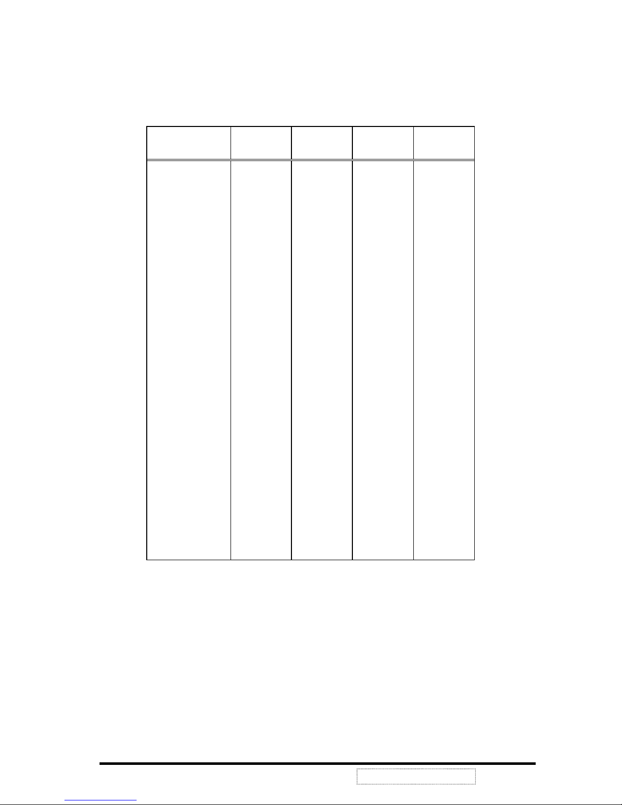
2-3 Factory Preset Timing
This timing chart is already preset for the TFT LCD monitors.
Timing Horizontal
Polarity
Horizontal
Frequency
Vertical
Polarity
Vertical
Frequency
VGA 640x350 + 31.47 kHz - 70.09 Hz
VGA 720x400 - 31.46 + 70.08
VGA 640x400 - 31.46 + 70.08
VGA 640x480 - 31.47 - 60.05
VESA 640x480 - 37.86 - 72.81
VESA 640x480 - 37.50 - 75.00
MAC 640x480 Composite 35.00 66.66
VESA 800x600 + 35.15 + 56.25
VESA 800x600 + 37.87 + 60.31
VESA 800x600 + 48.07 + 72.18
VESA 800x600 + 46.87 + 75.00
MAC 832x624 SOG 37.86 72.80
VESA
1024x768
- 48.36 - 60.00
VESA
1024x768
- 56.47 - 70.06
VESA
1024x768
- 58.03 - 71.91
VESA
1024x768
+ 60.02 + 75.02
MAC 1024x768 Composite 60.24 74.92
ViewSonic Corporation
5
Confidential --Do Not Copy VE510+-1
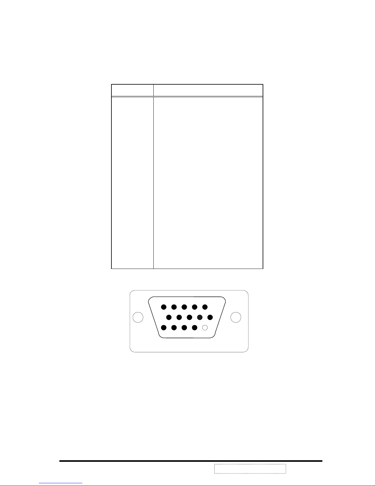
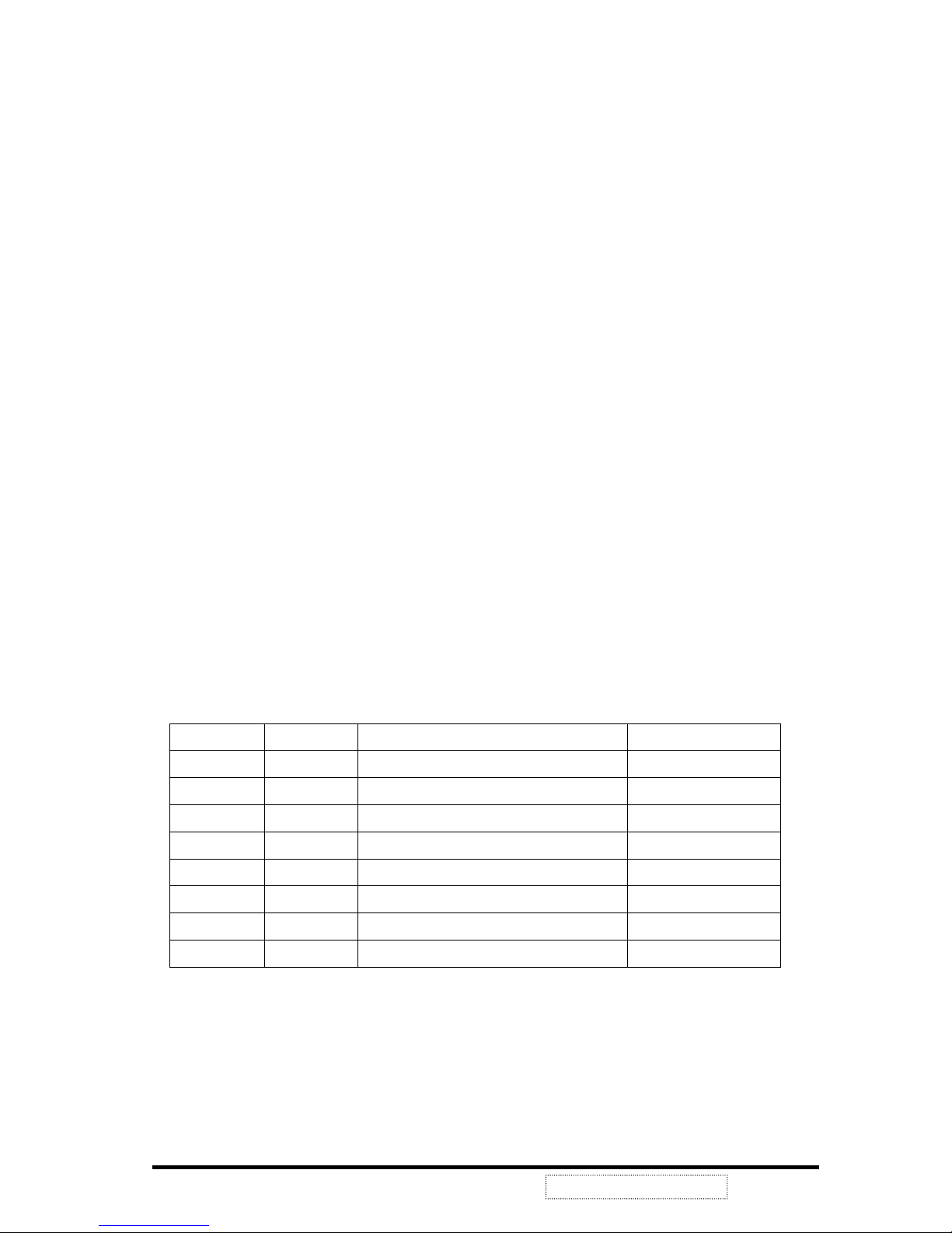
2-4 D-Sub connector Pin Assignment
The TFT LCD analog display monitors use a 15 Pin Mini D-Sub connector as
video input source.
Pin Number Pin Description
1 Red video input
2 Green video input
3 Blue video input
4 Ground
5 Ground
6 R video ground
7 G video ground
8 B video ground
9 +5V
10 Ground
11 No Connection
12 (SDA)
13 Horizontal sync (Composite sync)
14 Vertical sync
15 (SCL)
5
11
1
1
6
10
0
15
ViewSonic Corporation
6
Confidential --Do Not Copy VE510+-1
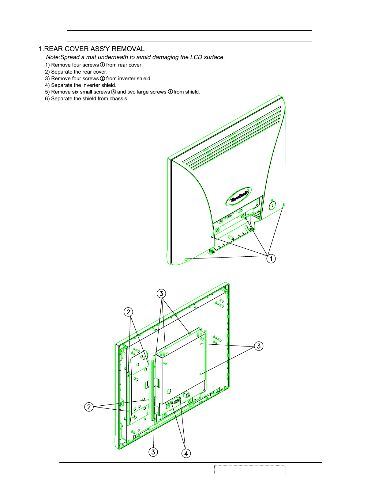
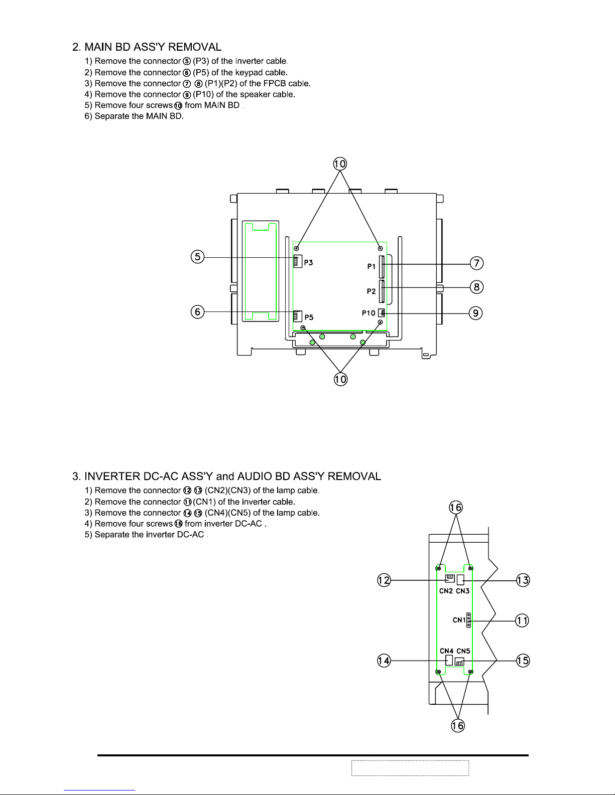
3. Disassembly / Assembly Instructions
ViewSonic Corporation
7
Confidential --Do Not Copy VE510+-1
ViewSonic Corporation
8
Confidential --Do Not Copy VE510+-1

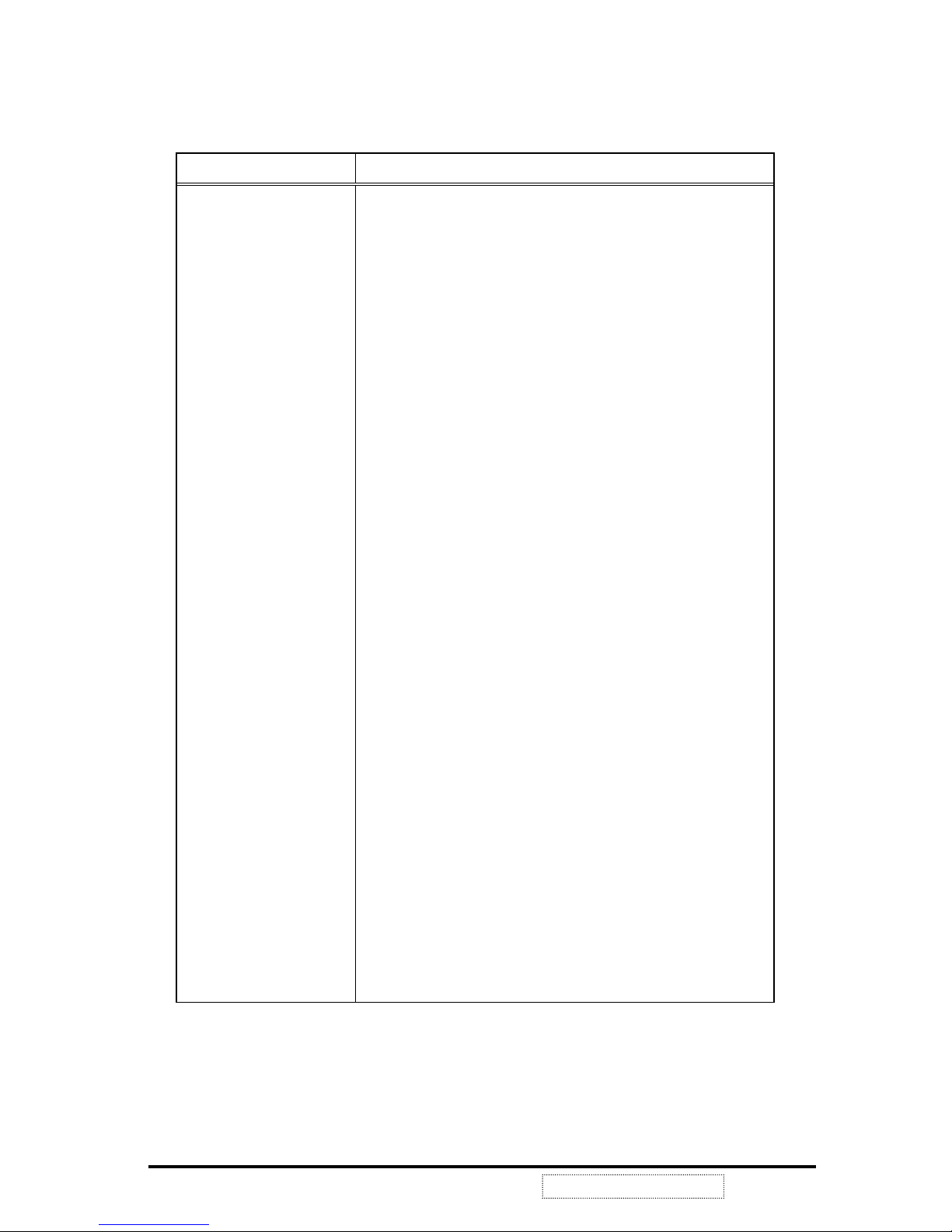
4. Electronic Circuit Description
4-1 Block Diagram
C
OMPLETE TFT LCD DISPLAY UNIT
AC Outlet
Adaptor
Main Board
Inverter
ControlBrightness
TFT
LCD
Panel
Digital
Signal
Analog
Signal
Video Card
12V
12V
VA C
ViewSonic Corporation
9
Confidential --Do Not Copy VE510+-1
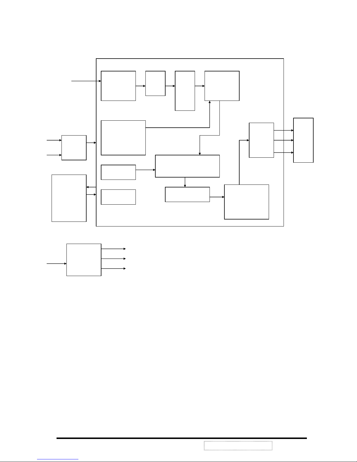
DC/DC
Converter
+5V
VLCD
+3.3V
+12V
Clamp
Video Gain
Video Level
ADC
MUX
Scaling
Engine
Sync detect
Phase calibration
OSD Generator
OSD overlay
MCU port
Dithering
Output control
Output
LCD
Panel
R, G, B
Sync
Buffer
U6
SYNCMOS
SM5964
MCU
HS
VS
HS
VS
U1 MRT
MASCOT
R, G, B offset
Gamma control
ViewSonic Corporation
10
Confidential --Do Not Copy VE510+-1
4-2 Main Board I/O Connections
P3 C
ONNECTION "INVERTER CONTROL"
Pin Description
1 N.C
2 CON
3 VEE
4 GND
5 VDD
P5 CONNECTION "OSD CONTROL"
Pin Description
1 POW 1
2 GND
3 LED1
4 LED2
5 KEY1
6 KEY2
7 KEY3
8 KEY4
9 +
10 11 MUTE
ViewSonic Corporation
11
Confidential --Do Not Copy VE510+-1
P1, P2 CONNECTION "VIDEO SIGNALOUT TOLCD PANEL"
P1 P2
Pin Description Pin Description
1 GND 1 GND
2 BO7 2 DCLK
3 BO6 3 GND
4 BO5 4 DE-O
5 BO4 5 VSYNC
6 GND 6 HSYNC
7 BO3 7 X
8 BO2 8 GND
9 BO1 9 BE7
10 BO0 10 BE6
11 GND 11 BE5
12 GO7 12 BE4
13 GO6 13 GND
14 GO5 14 BE3
15 GO4 15 BE2
16 GND 16 BE1
17 GO3 17 BE0
18 GO2 18 GND
19 GO1 19 GE7
20 GO0 20 GE6
21 GND 21 GE5
22 GO7 22 GE4
23 RO6 23 GND
24 RO5 24 GE3
25 RO4 25 GE2
26 GND 26 GE1
27 RO3 27 GE0
28 RO2 28 GND
29 RO1 29 RE7
30 RO0 30 RE6
31 GND 31 RE5
32 GND 32 RE4
33 X 33 GND
34 X 34 RE3
35 X 35 RE2
36 GND 36 RE1
37 RE0
38 VLCD
39 VLCD
40 GND
ViewSonic Corporation
12
Confidential --Do Not Copy VE510+-1
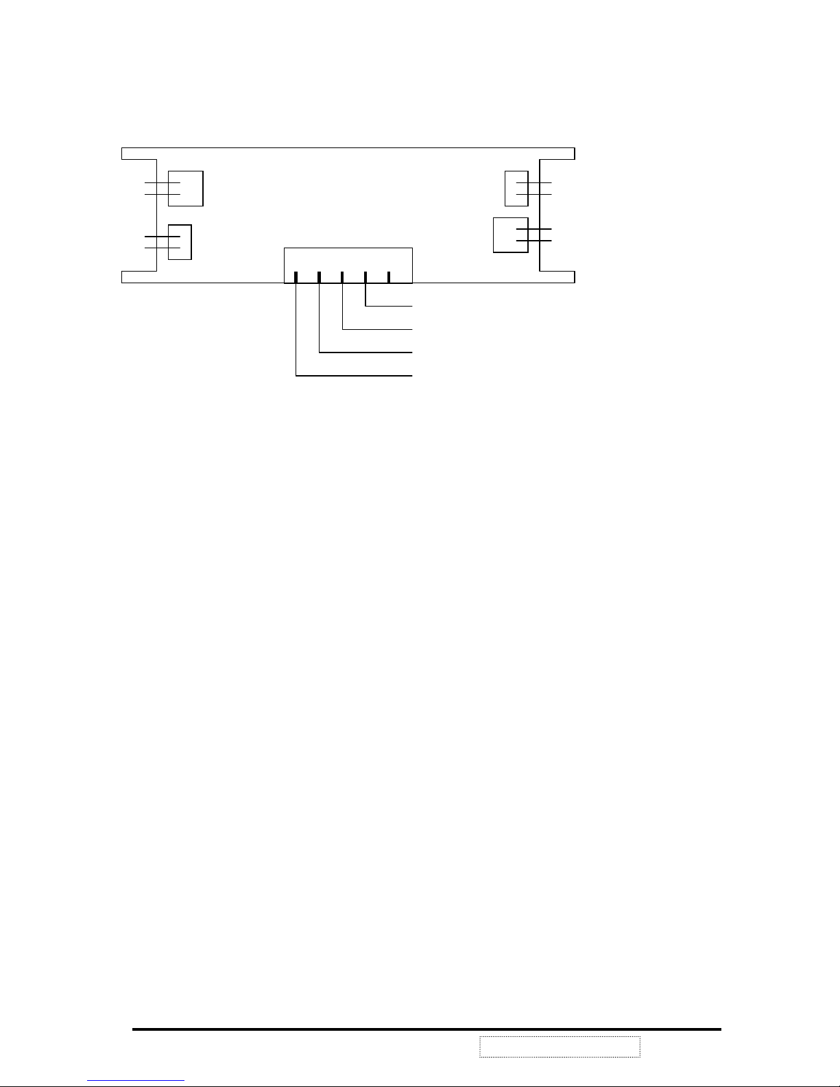
4-3 Inverter Board I/O Connections
NOTE: MANUFACTURER’S NAME MUST BE ON THE PRINTED SIDE FOR THE
INVERTER BOARD TO BE FACING UP.
4-4 Theory of Circuit Operation
VE510+ is a multi-frequency and multi-mode color TFT LCD monitor. It supports different
resolutions including XGA, SVGA, VGA and other various high resolution up to 1024x768 for
IBM, PC compatibles, Power PC and Macintosh. VE510+ uses a TFT LCD panel with a
0.297mm pixel pitch, provides 16.7 millions color images.
As the previous block diagram illustrates, VE510+ uses a highly integrated solution (U1:
Mascot V) that combines a high performance ADC with an advanced image process controller.
Using advanced image scaling algorithms, Mascot V has intelligently adaptive sub-algorithms
that will automatically optimize the display quality for different images – the text is sharper and
the graphics is smoother.
Furthermore, each TFT LCD monitor uses the 24LC02 (U14) chip to provide DDC1/2B¥ with
Analog Plug & Play, the DDC data format is EDID v1.3.
Digital process and control system allows users to control OSD menu values to change
monitor settings. The follow sections are major part discussions of the TFT LCD display
control board.
CON
VEE
GND
VDD
1
HV out
HV out
RTN
RTN
HV out
HV out
RTN
RTN
CN1
CN3
CN2
CN4
CN5
ViewSonic Corporation
13
Confidential --Do Not Copy VE510+-1
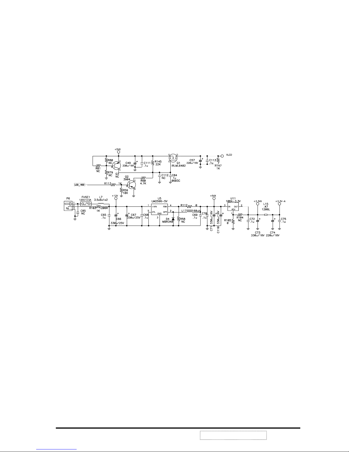
POWER SYSTEM
This product uses an external power adapter to provide DC+12V. It is the source of other
voltages +5VX, 3.3VX, and VLCD.
The voltage of +5VX is produced by regulator LM2596-5V (U5) and external components that
can realize DC to DC conversion from +12V to +5V. For some chips (MPU, ADC) that are
sensitive to any voltage variance, we need LDO 1084-3.3V (U11) to produce a stable voltage
3.3VX.
There is still an important consideration about power consumption. We must greatly reduce
the power consumption even up to 90% in power saving mode. So we need to switch off the
power that needn’t exist when the system enters to this mode. We use the P-channel
MOSFET TRLML6402 (Q1) to control the on/off state of the panel’s power VLCD.
See FIG1-1.
FIG1-1
ViewSonic Corporation
14
Confidential --Do Not Copy VE510+-1
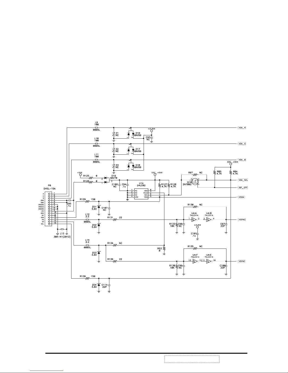
ANALOG SIGNAL INPUT and EDID
See FIG1-2.
FIG1-2
ViewSonic Corporation
15
Confidential --Do Not Copy VE510+-1
This product uses the internal function of Mascot V (U1) as a signal detector in order to
support separate SYNC, composite SYNC and SYNC on GREEN signals. The analog input
Horizontal and Vertical Sync signals pass through the Schmitt trigger buffer U4 to stabilize
then input to Mascot U1 pin38 VGA_VSYNC, pin39 VGA_HSYNC or pin40 SOGI and the
image processing. Then Mascot will detect the signal type if it is separate SYNC, composite
SYNC or SOG. MPU (U6) reads the input signal type from IIC protocol and does the correct
procedure to generate the proper signals to the whole system.
24LC02 (U14) chip provide DDC1/2B¥ with Analog Plug & Play, and the DDC data format is
EDID v1.3.
 Loading...