

ViewSonic VG171/b-1, VLCDS23303-1, VLCDS233031b Service manual
Service Manual
ViewSonic VG171/b-1
Model No. VLCDS23303-1/-1b
17” Color TFT LCD Display
ViewSonic
(VG171/b-1_SM_501- Rev. 1a – Jan 2003)
381 Brea Canyon Road, Walnut, California 91789 USA - (800) 888-8583
Copyright
Copyright
reproduced, transmitted, transcribed, stored in a retrieval system, or translated into any language or
computer language, in any form or by any means, electronic, mechanical, magnetic, optical, chemical,
manual or otherwise, without the prior written permission of ViewSonic Corporation.
Disclaimer
ViewSonic makes no representations or warranties, either expressed or implied, with respect to the
contents hereof and specifically disclaims any warranty of merchantability or fitness for any particular
purpose. Further, ViewSonic reserves the right to revise this publication and to make changes from time
to time in the contents hereof without obligation of ViewSonic to notify any person of such revision or
changes.
Trademarks
ViewSonic is a registered trademark of ViewSonic Corporation.
All other trademarks used within this document are the property of their respective owners.
2002 by ViewSonic Corporation. All rights reserved. No part of this publication may be
¤
Revision History
Revision Date Description Of Changes Approval
1a 01/28/03 Initial Release DCN-2962 C. Shen
ViewSonic Corporation
i
Confidential – Do Not Copy
VG171/b1
FCC Statement
This equipment has been tested and found to comply with the limits of Class B digital device, pursuant
to part 15 of the FCC Rules. These limits are designed to provide reasonable protection against
harmful interference in a residential installation. This equipment generates uses and can radiate radio
frequency energy, and for if not installed and used in accordance with the instructions, may cause
harmful interference to radio communication. However, there is no guarantee that the interference will
not occur in a particular installation. If this equipment does cause unacceptable interference to radio or
television reception, which can be determined by turning the equipment off and on, the user is
encouraged to try to correct the interference by one or more of following measures
Reorient or relocate the receiving antenna.
Increase the separation between equipment and receiver.
Connect the into an outlet on circuit different from that to which the receiver is
connected.
Consult the dealer or an experience radio/TV technician for help.
Κ
FCC Warning
To assure continued FCC compliance, the user must a grounded power supply cord and the provided
shielded video interface cable with bonded ferrite cores. Also, unauthorized changes or modifications
to ViewSonic products will void the usercs authority to operate this device. Thus ViewSonic will not be
held responsible for the product and its safety.
CE Certification
This device complies with the requirements of the ECC directive 89/3366/EEC with
regard to sElectromagnetic compatibility.s
Safety Guidelines
Caution: Use a power cable that is properly grounded. always use the AC cords listed below for each
Κ
area
USA (UL)
Canada (CSA)
Germany (VDE)
Switzerland (SEV)
Britain (BASE/BS)
Japan (Electric Appliance Control Act)
In other areas, use AC cord which meets the local safety standards.
ViewSonic Corporation
ii
Confidential – Do Not Copy
VG171/b1

Table of Contents
Chapter 1 Feature 1-1
1.1. On-Screen-Display Controls………………………………………………. 1-1
1.2. Power Supply Support…………………………………………………….. 1-1
1.3. Power Saving System……………………………………………….......... 1-1
1.4. Frequency Range …………………………………………………………. 1-1
Chapter 2 Specification…………………………………………………………………2-1
Chapter 3 On Screen Display…………………………………………………………. 3-1
Chapter 4 Block Diagram………………………………………………………………. 4-1
Chapter 5 PCB I/O Connections 5-1
5.1. Main Board I/O Connections………………………………………………. 5-1
5.2 Inverter Board I/O Connections…………………………………………… 5-2
Chapter 6 Timing Chart 6-1
Chapter 7 Trouble Shooting 7-1
7.1. Monitor display Nothing …………………………………………………… 7-1
7.2. R, G, B Color not Correct………………………………………………….. 7-2
7.3. Improper Quality is not Good……………………………………………..... 7-3
7.4. Trouble of DC-DC Converter…………………………………………….......7-4
7.5. Trouble of DDC Reading……………………………………………………. 7-5
Chapter 8 Theory of Circuit Operation………………………………………………..8-1
8.1.Summary……………………………………………………………………….8-18
8.2.Analog Signal and EDID Process……………………………………...........8-2
8.3. Power and CPU Control System……………………………………………8-3
8.4. TMDS Signal Process………………………………………………….........8-4
8.5. Analog – Digital Conversion Process……………………………………....8-9
8.6. Digital Signal Multi-Process………………………………………..............8-11
8.7. Low Voltage Different Signal Circuit………………………..................... 8-20
8.8. MTV112MN32 Description…………………............................................8-21
Chapter 9 Pin Assignment………………………………........................................9-1
9.1.15 Pin Mini D-Sub Connec
9.2. 24 Pin DVI-D Connector
tion………………............................................9-1
…………………............................................ 9-2
ViewSonic Corporation
iii
Confidential – Do Not Copy
VG171/b1

Chapter 10 Waveforms…………………………………………………………10-1
Chapter 11 Spare Parts List…………………………………………………11-1
11.1.VG171 ………………………………………………………………..11-1
11.2 VG171b……………………………………………..........................11-2
Chapter 12 Complete Parts List…………………………………………........12-1
12.1 VG171……………………………………………………………………12-1
12.2 VG171b………………………………………………………………….12-17
Chapter 13 Disassembly Instructions………………………………………13-1
13.1 Rear Cover Ass’Y Removal..........................................................13-1
13.2 Main BD Ass’y Removal…………………………………………......13-2
13.3 Inverter DC-AC Ass’y Removal…................................................13-2
13.4 Exploded Diagram…....................................................................13-2
Chapter 14 Schematic Diagrams ……………………………………………14-1
Chapter 15 PCB Layout............................................................................. 15-1
ViewSonic Corporation
vi
Confidential – Do Not Copy
VG171/b1
1. Feature
I
VG171 is a world class TFT LCD analog and digital display monitor that
includes the following features.
1. Digital On Screen Display Controls
User friendly buttons [ ] allowing for picture perfect quality.
1 ϯ Ϧ 2
2. Power Supply Support
Ability to accept voltages from 100~240Vac, thus allowing a full
range of input AC power supply.
3. Power Saving System
This environmental friendly product is able to reduce power consumption
by more than 90% in Active Off Mode.
4. Frequency Range
Monitor can support video standards from VGA to SXGA, where Horizontal
frequency ranges from 30~82 kHz and Vertical frequency ranges from
50~75 Hz.
ViewSonic Corporation
2
Confidential – Do Not Copy
VG171/b1
2. Specification
Characteristic Description
LCD Panel Hyundai 17.0” HT17E11-300
Maximum Viewing
Angles
Signal Input VideoΚRGB analog Video : Digital
125 degree(V), 150 degree(H). Typ. (CRЊ10)
Sync : H.V. Separate Sync,Composite. SOG
(TTL Compatible).
Horizonta
lΚ30 to 82 KHz
Sync : TMDS
Vertical Κ50 to 75Hz
Connector
Maximum Resolution Horizontal : 1280
Video Bandwidth 135 MHz (Max)
Display Area 337.920 mm (H) x 270.336 mm (V)
Power Voltage 100~240Vac @ 50~60 Hz (auto switch), 12Vdc 4.0A (Max.)
Analog : 15 Pin Mini D-Sub
Digital : 24 PIN DVI-D connector
Vertical : 1024
Power Consumption 40W max.
Operating Conditions Temperature : 32л to 104л (0к to 40к)
Humidity : 10% to 90% (no condensation)
Altitude : To 10,000 feet
Storage Conditions Temperature : -4л to +140л (-20к to +60к)
Humidity : 10% to 90% (no condensation)
Altitude : To 40,000 feet
Dimensions Physical : 410mm (W) x 410mm (H) x 167mm (D)
Weight Net : 6.5Kg
Gross : 8.5Kg
ViewSonic Corporation
3
Confidential – Do Not Copy
VG171/b1
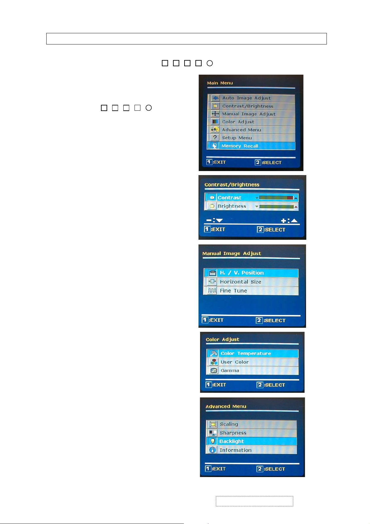
3. On Screen Display
I
I
OSD (On Screen Display) function is supported on each the TFT LCD analog display monitors and is
controlled by four easy to use buttons :
2
Ϧ
ϯ
1
Main Menu
Contrast / Brightness
1 ϯ Ϧ 2
Manual Image adjust
Color adjust
Advanced Menu
ViewSonic Corporation
4
Confidential – Do Not Copy
VG171/b1
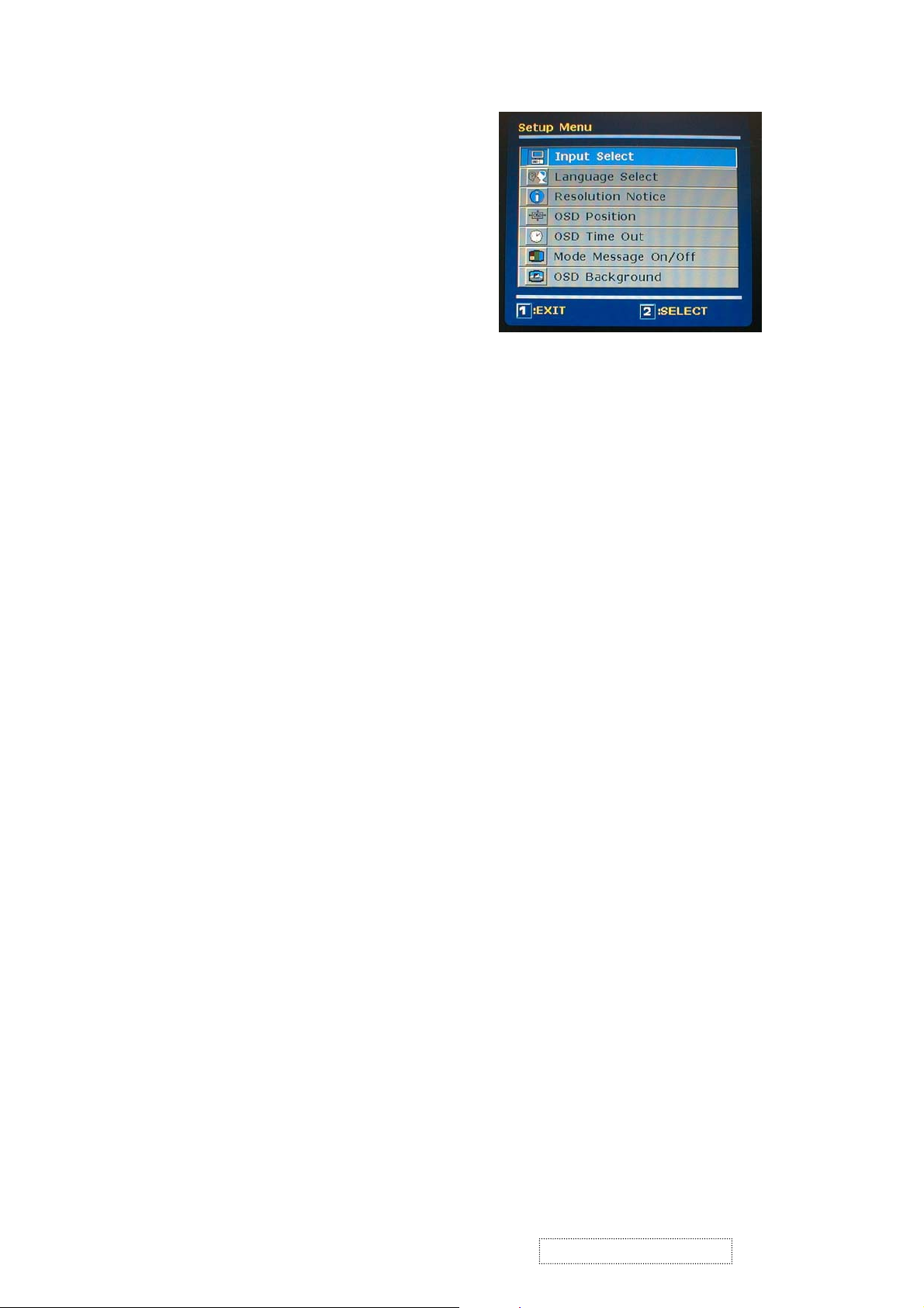
Setup Menu
ViewSonic Corporation
5
Confidential – Do Not Copy
VG171/b1
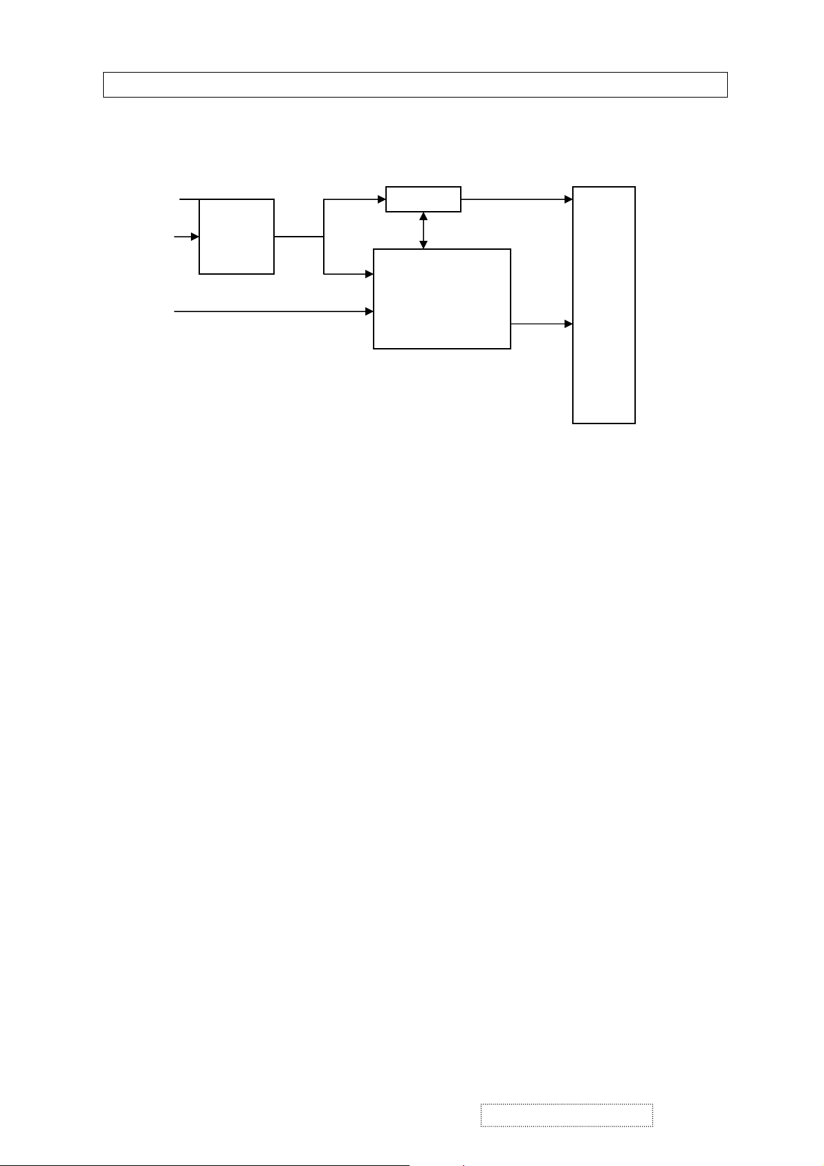
C
OMPLETE TFT LCD DISPLAY UNIT
4. Block Diagram
AC Outlet
Video Card
Adaptor
Analog/Digital
Signal
12V
12V
Inverter
ControlBrightness
Main Board
650 Vac
Digital
Signal
Lamp
TFT
LCD
Panel
ViewSonic Corporation
6
Confidential – Do Not Copy
VG171/b1
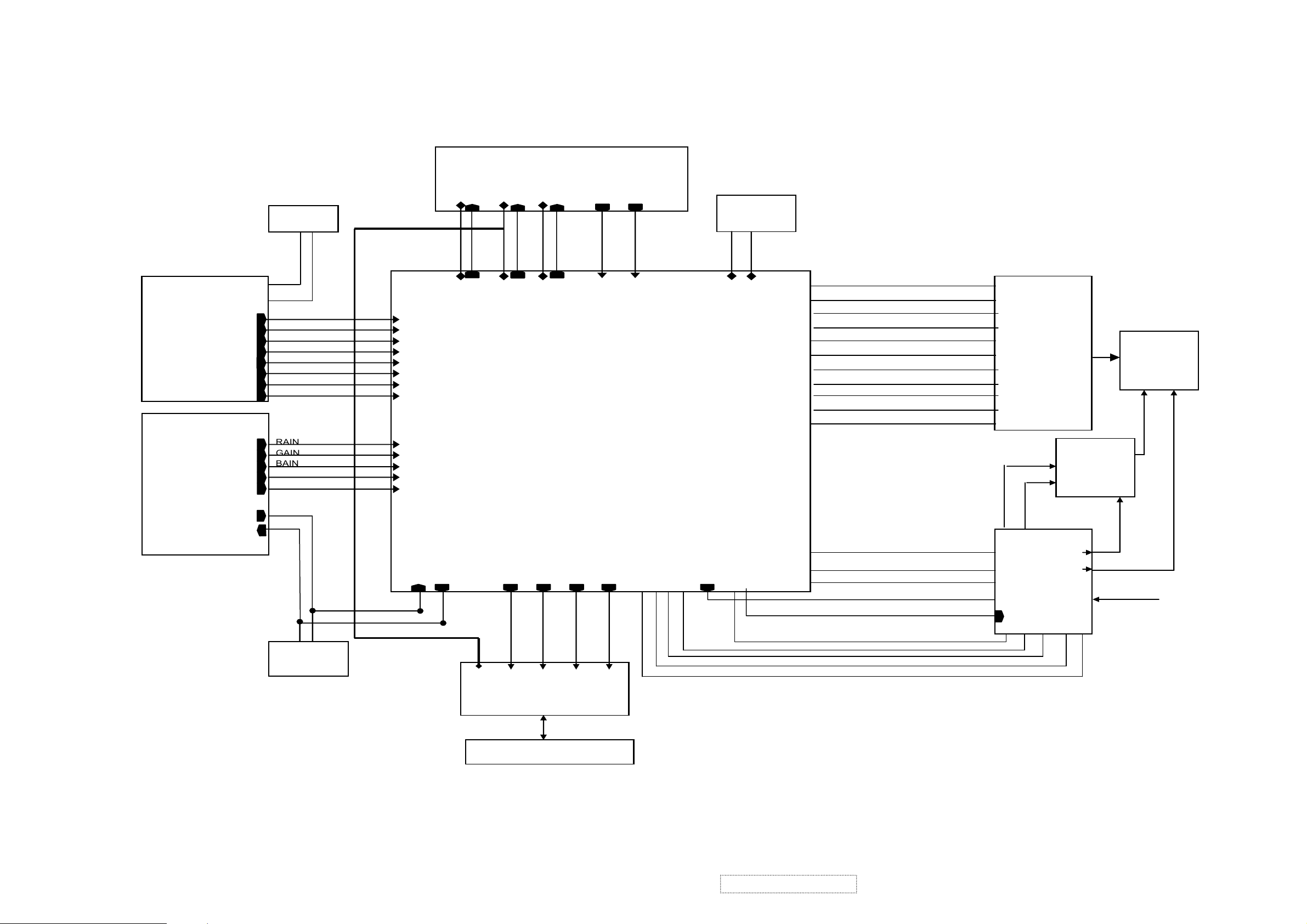
GRAPHICSIN
Fl
(8M)
V18
Digital EDID
V3.3V18A
3.3V DVI
3.3V ADC
PWMOUT
BKLON
LCD ON
DMPS
DC
12V (J8)
5V
12V
LVD S
t
U6
SDA
ashMemory
U13
ROMWEn
ROMOEn
A{19:1}
D{15:0}
SCL
NMI
U3
RESETn
EPROM
U4
NMI
D{15:0}
ROMWEn
ROMOEn
A{19:1}
SCL SDA
RX2p
RX2m
P1
RX1p
RX1m
RX0p
RX0m
RXCm
RXCm
GRADHICSIN
(Analog) Input CON
RAIN
GAIN
J1
BAIN
AHSYNC
AVSYNC
RxD
TxD
CLK
Data
AHSYNC
AVSYNC
RX2p
RX2m
RX1p
RX1m
RX0p
RX0m
RXCp
RXCm
RAIN
GAIN
BAIN
AHSYNC
AVSYNC
RXD
outpu
(U8, U 9)
17” TFT
LCD Panel
Lamp 5V
SDA
SCL
A{19:1}
D{15:0}
ROMOEn
ROMWEn
NMI
RESETn
207 208
PW131
U5
DCLK
DHS
DVS
DEN
DRE(7:0)
DGE(7:0)
DBE(7:0)
DRO(7:0)
DGO(7:0)
DBO7:0)
LVD SON
DCLK
DHS
DVS
DEN
DRE(7:0)
DGE(7:0)
DBE(7:0)
DRO(7:0)
DGO(7:0)
DBO7:0)
LVD SON
04_PW131
B/L Inverter
Brightness
BKLON
DPMS
TXD
LED1
LED2
CSOn
ROn
VI8
V18A
V33
Pwhout
3.3VDVI
LCD ON
3.3VADC
LCD ON
BK LON
LCDON
D{15:0}
Analog EDID
U1
D(8.0)
LED1
Display Board
ViewSonic Corporation
CS0n
LED2
U4, J7
CS0n
RDn
RDn
7
Confidential – Do Not Copy
VG171/b1
5. PCB I/O Connections
5.1Main Board I/O Connections
J4 C
ONNECTION "OSD CONTROL"
Pin Description
1 POW 2
2 POW 1
3 GND
4 LED2
5 SN1
6 SELECT
7 +
8 FUN
9 -
J7 CONNECTION "INVERTER CONTROL"
Pin Description
1 No Connection
2 Brightness Adjustment
3 Backlight ON/OFF control
4 Ground1
5 +12V
ViewSonic Corporation
8
Confidential – Do Not Copy
VG171/b1
J5 CONNECTION "VIDEO SIGNAL OUT TO LCD PANEL"
Pin Description
1 LVCD
2 LVCD
3 LVCD
4 NC
5 DE
6 NC
7 GND
8 TXE3+
9 TXE3-
10 TXECK+
11 TXECK12 TXE2+
13 TXE214 GND
15 TXEij+
16 TXEij-
17 TX03+
18 TX0319 TXOCK+
20 TXOCK21 GND
22 TX02+
23 TX0224 TX01+
25 TX0126 TXOij+
27 TXOij-
28 RO2
29 RO1
30 RO0
31 GND
ViewSonic Corporation
9
Confidential – Do Not Copy
VG171/b1
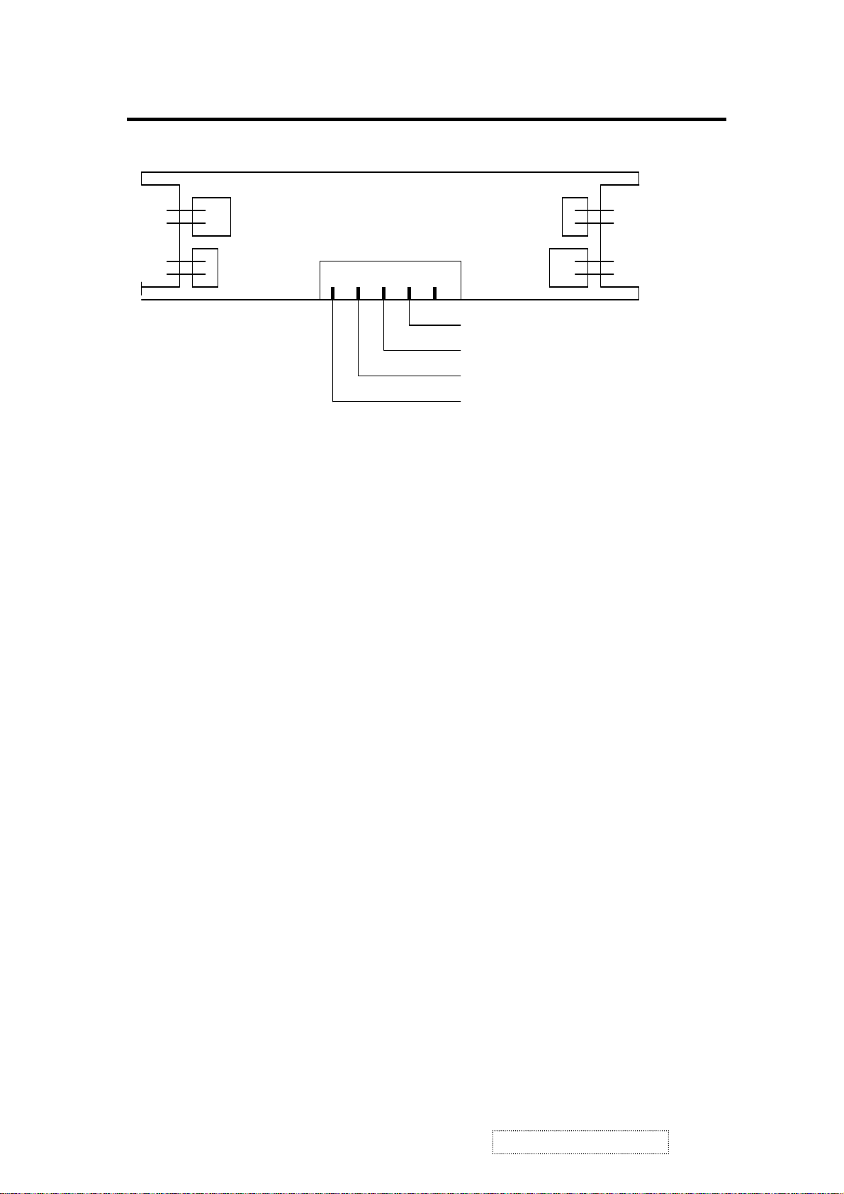
5.2 Inverter board I/O connections
HV out
HV out
RTN
RTN
CN1
CN3
CN2
1
TDK
RTN
RTN
HV out
HV out
Brightness Adjustment
Backlight ON/OFF control
GND
12V
NOTE: MANUFACTURER’S NAME MUST BE ON THE PRINTED SIDE FOR THE
INVERTER BOARD TO BE FACING UP.
ViewSonic Corporation
:
Confidential – Do Not Copy
VG171/b1
6. Timing Chart
This timing chart is already preset for the TFT LCD monitors.
Timing
VGA 640x350 + 31.46 - 70.08
VGA 720x400 - 31.46 + 70.08
VGA 640x400 - 31.46 + 70.08
VGA 640x480 - 31.47 - 60.05
VGA 640x480 - 35.0 - 66.67
VESA 640x480 - 37.86 - 72.81
VESA 640x480 - 37.50 - 75.00
VESA 800x600 + 37.87 + 60.31
VESA 800x600 + 48.07 + 72.18
VESA 800x600 + 46.87 + 75.00
VESA 832x624 + 49.72 + 75.54
VESA 1024x768 - 48.36 - 60.00
Horizontal
Polarity
Horizontal
Frequency
(KHz)
Vertical
Polarity
Vertical
Frequency
(Hz)
VESA 1024x768 - 56.47 - 70.06
VESA 1024x768 - 58.03 - 71.92
VESA 1024x768 + 60.02 + 75.02
VESA 1280x1024 + 63.98 + 60.02
VESA 1280x1024 + 79.97 + 75.02
ViewSonic Corporation
21
Confidential – Do Not Copy
VG171/b1

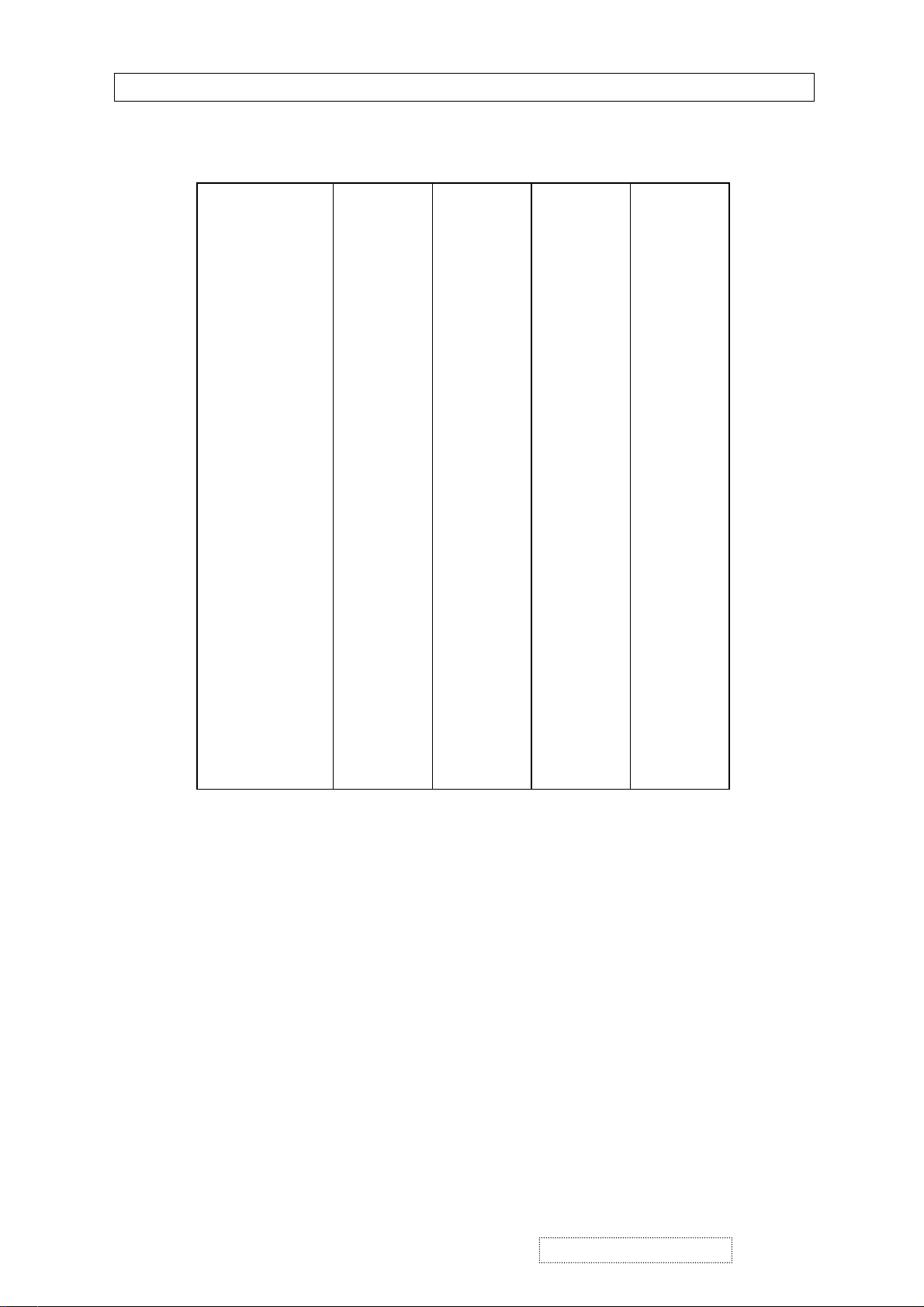
MONITOR DISPLAY NOTHING
Start
7. Trouble Shooting
LED is lighting?
Yes
LED is green.
Yes
Is backlight on?
Yes
U8, U9 okay?
Yes
Panel input okay.
N0
N0
N0
N0
N0
1. Is adaptor’s output+12V?
2. Is DC Jack connector okay?
3. Is connector of display B/D
okay?
3. Is DC-DC okay?
4. Check LED signal?
5 Check U14 U3 ok?
Is it in power saving?
1. Check video cable
2. Is the timing supported?
1. Check the inverter is okay.
2. Check the connector of inverter
1. Check U8, U9 V33 ok?
2. Check LHS, LVS, LDE, LCK ok?
It means data to panel
1. Is J6 connected well?
2. Check LCD VDD
3. Is panel okay?
END
ViewSonic Corporation
22
Confidential – Do Not Copy
VG171/b1
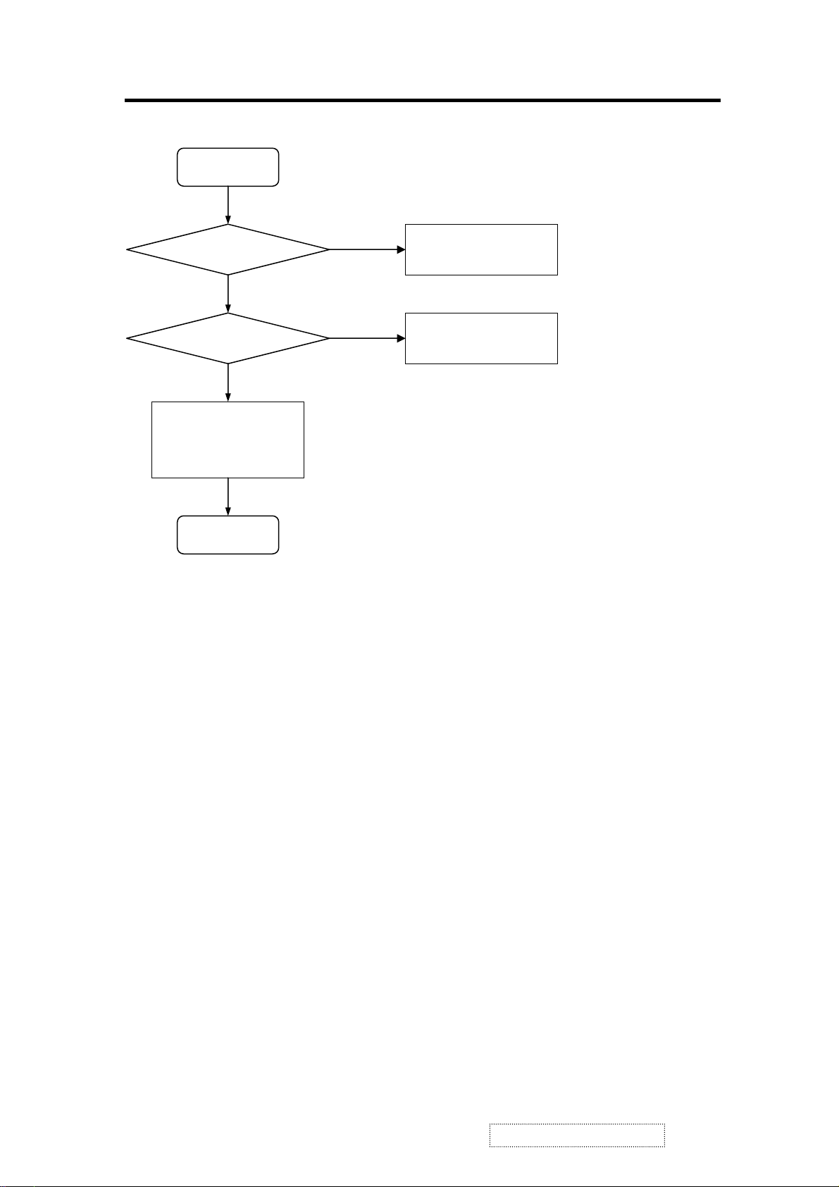
R, G, B COLOR IS NOT DISPLAY CORRECT
Start
Is input signal okay?
Yes
Is U5B output correct?
Yes
1. Is J6 connected okay?
2. Is panel working okay?
3. Check OSD color setting
END
N0
N0
1. Check video cable
2. Check settings of host system
1. Check resistor arrays of U5B
out dot
2. Check power of voltage
ViewSonic Corporation
23
Confidential – Do Not Copy
VG171/b1
TROUBLE OF DC-DC CONVERTER
Start
Is +12V correct?
Is +5V correct?
3.3/2.5V okay?
END
Yes
Yes
Yes
N0
N0
N0
The voltage is about + 12V
1. Check power adaptor
2. Check power cable
3. Check F1
The voltage is around + 4.9V on
1. Check U10 output
2. Check F2
3 Check D9
1. Check U13, Q6, Q8 for 3.3V
2. Check U11 and U12 for 1.8V
C43.
ViewSonic Corporation
24
Confidential – Do Not Copy
VG171/b1
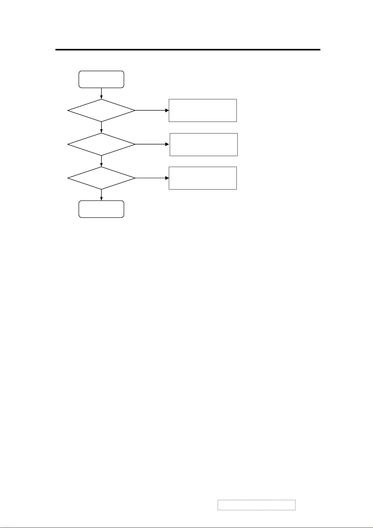
TROUBLE OF DDC READING
Start
Analog DDC OK?
Yes
N0
Support DDC1/2B
1. Analog cable ok?
2. Check signal of U1 (SDA, SCL)
3. Check U15
4. Check IIC protocol
5. Is Analog cable Pin10 Ground?
Digital DDC OK?
Yes
END
N0
Support DDC2B
1. DVI cable ok?
2. Check signal of U6 (SDA, SCL)
3. Check IIC protocol
ViewSonic Corporation
25
Confidential – Do Not Copy
VG171/b1
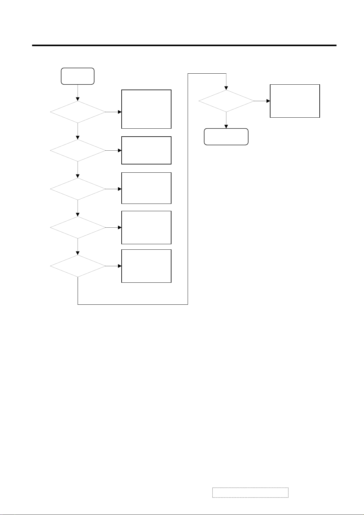
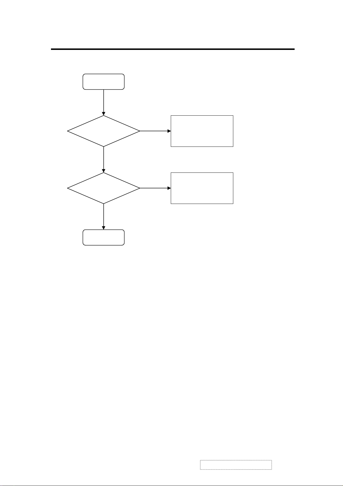
IMAGE QUALITY IS NOT GOOD
Start
Image size ok?
Yes
Vertical Stripe?
N0
Horizontal Stripe?
N0
Position Shift?
N0
Yes
Yes
Yes
It means image exceed or less than
display area
1. Is scaling to full screen
2. Do auto adjustment
function work well
1. Do auto adjustment
function work well
1. Do auto adjustment
function work well
1. Do auto adjustment
function work well
Color Unbalance?
N0
END
1. Select COOL, STD and WARM
settings of color temperature
Yes
2. Adjust user color R,
G, B
N0
Too dark or bright
N0
1. Adjust contrast &
Yes
black level
ViewSonic Corporation
26
Confidential – Do Not Copy
VG171/b1

8. Theory of Circuit Operation
This monitor is a, multi-frequency and multi mode color TFT LCD monitor. It supports
different resolutions including SXGA, SVGA, VGA and other various resolution modes up to
1280x1024 for IBM, PC compatibles and Power PC. It uses a TFT LCD panel with a
0.264mm pixel pitch, provides 16.2 Million colors.
As the previous block diagram illustrates, this monitor uses the image processing engine (U5)
for resolution scaling from its preset values. This image processing engine (U5) includes
analog video gain control, video level control, ADC, analog/digital signal selection, resolution
scaling, OSD mix, and the output driving sections. The sampling clock generator of ADC and
output clock generator are also integrated in this chip.
Furthermore, each TFT LCD monitor uses the 24LC21 (U10) chip to provide DDC1/2B¥ with
Analog Plug & Play, the DDC data format is EDID v1.3.
Upon receiving video signal input, the Analog Interface Controller (Digital Process and
Control System) will trigger the mode detection function such that the PW131 can use the
internal mode table preset information to drive the Analog Interface Controller. In addition, the
preset values can determine A/D converter clock; LCD pixel clock; line buffer input/output
rate; V-Sync and H-Sync pulse width; back porch and front porch to provide optimal
performance for the TFT LCD monitors.
Digital process and control system allows users to control OSD menu values to change
monitor settings. The following sections are major part discussions of the control board for
TFT LCD panel.
ViewSonic Corporation
27
Confidential – Do Not Copy
VG171/b1
 Loading...