

Page 1
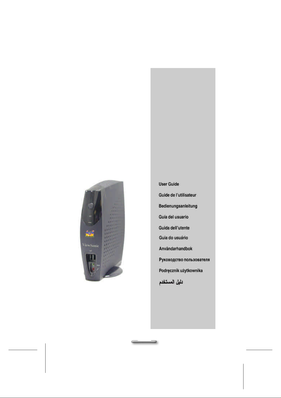
ViewBox 100
/802.11b/
HPNA
1
Page 2

Copyright
serial number of this unit
in the space provided and retain this booklet as a permanent record of your purchase to aid in
Copyright© ViewSonic Corporation, 2001. All right reserved.
ViewSonic, the three birds logo, OnView, ViewMatch, and ViewMeter are registered trademarks of ViewSonic
Corporation.
Disclaimer: ViewSonic
nor for incidental or consequential damages resulting from furnishing this material, or the performance or use this
product.
ViewSonic Corporation reserves the right to change product specification without notice. Information in this
document may change without notice.
No part of this document may be copied, reproduced, or transmitted by any means, for any purpose without prior
written permission from ViewSonic Corporation.
®
Corporation shall not be liable for technical or editorial errors or omissions contained herein;
Electronic Warranty Registration
Register your ViewBox at www.viewsonic.com. It’s fast, easy, and will simplify future support needs.
For Your Records
The serial number of this product is on the back of the unit. You should note the
identification in the event of theft or loss.
Product Name: ViewBox 100, 802.11b, HPNA
Model Number: VSVBX 23771-1M/ VSVBX 23671-1M(802.11b)/
VSVBX 23692-1M(HPNA)
Serial Number:
Purchase Date:
Power Cord Safety Guidelines
Caution: Use a power cable that is properly grounded. Always use the AC cords listed below for each area:
In other areas, use AC cord which meets local safety standards.
USA....……………………..UL
Canada……………………CSA
Germany…………………..VDE
Switzerland………………..SEV
Britain………………………BASEC
Japan………………………Appliance Control Act
2
Page 3
AC PLUG CORD PRECAUTIONS FOR THE UNITED KINGDOM
FOR YOUR SAFETY PLEASE READ THE FOLLOWING TEXT CAREFULLY
IF THE FITTED MOULDED PLUG IS UNSUITABLE FOR THE SOCKET OUTLET THEN THE PLUG SHOULD BE
CUT OFF AND DISPOSED OF SAFELY.
THERE IS A DANGER OF SEVERE ELECTRICAL SHOCK IF THE CUT OFF PLUG IS INSERTED INTO AN
APPROPRIATE SOCKET.
If a new plug is to be fitted, please observe the wiring code as shown below.
If in any doubt, please consult a qualified electrician.
WARNING: THIS APPLIANCE MUSR BE EARTHEED.
IMPORTNT: The wires in this mains leas are colored in accordance with the following code:
Green-and-Yellow: …….Earth
Blue: ……………………..Neutral
Brown: …………………..Live
If the colored wires of the mains leas if this appliance do not correspond with the colored marking identifying the
terminals in your plug, processed as follows:
The wire which is colored GREEN-AND-YELLOW must be connected to the terminals in the plug which is marked
by the letter E or by the Earth symbol or colored GREEN or GREEN-AND-YELLOW.
The wire which is colored BLUE must be connected to the terminal in the plug which is marked with the letter N or
colored BLACK. The wire which is colored BROWN must be connected to the terminal in the plug which the letter L
or colored RED.
IMPORTANT NOTICE CONCERNING POWER CORD SELECTION
The power cord set for this unit has been enclosed and has been selected according to the country of destination
and must be used to prevent electric shock. Use the following guidelines if it is necessary to replace the original
cord set, or if the cord set is not enclosed.
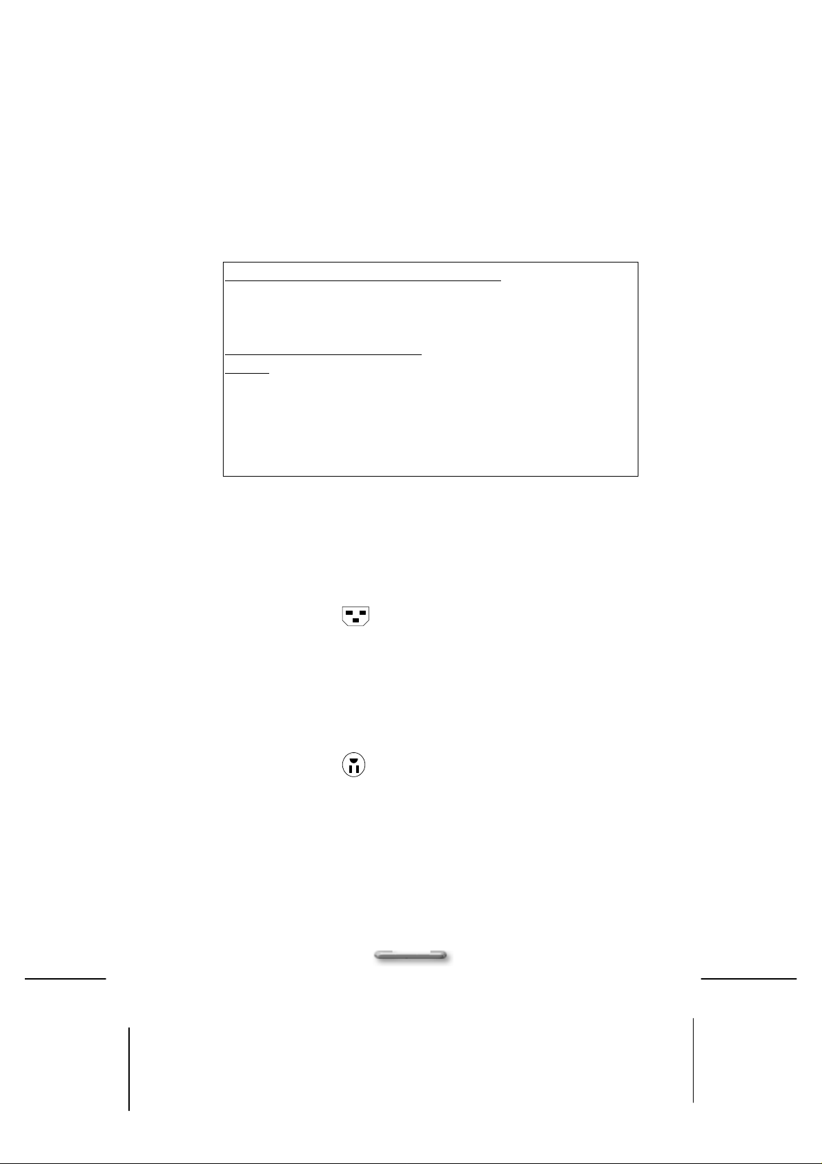
The female receptacle of the cord set must meet CEE-22 requirements and will look like Figure 1 below:
Figure1
For the United States and Canada
In the United States and Canada the male plug is a NEMA5-15 style (Figure2), UL Listed, and CSA Labeled. For
units that are mounted on a desk or table, type SVT or SJT cord sets may be used. For units that sit on the floor,
only SJT type cord sets may be used. The cord set must be selected according to the current rating for your unit.
Please consult Table A below for the selection criteria for power cords used in the United States and Canada.
Figure2
For European Countries
In European you must use a cord set which is appropriate for the receptacles in your country. The cord set is HARCertified, and a special mark that will appear on the outer sheath, or on the insulation of one of the inner
conductors.
If you have ant questions concerning which proper power cord to use, please consult with the dealer from whom
you have purchased your ViewBox.
3
Page 4
Table A
Cord Type Size of Conductors In Cord Maximum Current Rating of Unit
SJT
SVT
18AWG
16AWG
14AWG
18AWG
17AWG
10Amps
12Amps
12Amps
10Amps
12Amps
Important Safety Instructions
Read these instructions carefully. Save these instructions for future reference.
1. Follow all warnings and instructions marked on the product.
2. Unplug this product from the wall outlet before cleaning. Do not use liquid cleaners or aerosol clears. Use a
damp cloth for cleaning.
3. Do not use this product near water.
4. Do not place this product on an unstable cart, stand, or table. The product may fall, causing serious damage
to the product.
5. Slots and openings in the cabinet and the back or bottom are provided for ventilation; to ensure reliable
operation of the product and to protect it from overheating, these openings must not be blocked or covered.
Placing the product should never be placed near or over a radiator or heat register, or in a built-in installation
unless proper ventilation is provided.
6. This product should be operated from the type of power indicated on the marking label. If you are not sure
of the type of power available, consult your dealer or local power company.
7. Do not allow anything to rest on the power cord. Do not locate this product where persons will walk on the
cord.
8. If an extension cord is used with this product, make sure that the total ampere rating of the equipment
plugged into extension cord does not exceed the extension cord ampere rating. Also, make sure that the
total rating of all products plugged into the wall outlet does not exceed the fuse rating.
9. Never push objects of any kind into this product through cabinet slots as they may touch dangerous voltage
points or short out parts that could resulting a fire or electronic shocks. Never spill liquid of any kind on the
product.
10. To avoid electronic shock, do not open the cover. There are no user-serviceable parts inside.
11. Use minimum No 26AWG Wire for telephone cable.
12. Unplug this product from the wall outlet and refer servicing to qualified service personal under the following
conditions:
a. When the power cord or plug is damaged or frayed.
b. If liquid has been spilled into the product.
c. If the product has been exposed to rain or water.
d. If the product does not operate normally when the operating instructions are followed. Adjust only
those controls that are covered by the operating instructions since improper adjustment of other
controls may result in damage and will often require extensive work by a qualified technician to
restore the product to normal condition.
e. If the product has been dropped or cabinet has been damaged.
f. If the product exhibits a distinct change in performance, indicating a need for service.
4
Page 5

Federal Communication Commission Interference Statement
This equipment has been tested and found to comply with the limits for a Class B digital device, pursuant to Part 15
of the FCC Rules. These limits are designed to provide reasonable protection against harmful interference in a
residential installation. This equipment generates, uses and can radiate radio frequency energy and, if not installed
and used in accordance with the instructions, may cause harmful interference to radio communications. However,
there is no guarantee that interference will not occur in a particular installation. If this equipment does cause
harmful interference to radio or television reception, which can be determined by turning the equipment off and on,
the user is encouraged to try to correct the interference by one of the following measures:
? Reorient or relocate the receiving antenna.
? Increase the separation between the equipment and receiver.
? Connect the equipment into an outlet on a circuit different from that to which the receiver is
connected.
FCC Caution:
To assure continued compliance, (example - use only shielded interface cables when connecting to computer or
peripheral devices) any changes or modifications not expressly approved by the party responsible for compliance
could void the user's authority to operate this equipment.
This device complies with Part 15 of the FCC Rules. Operation is subject to the following two conditions: (1) This
device may not cause harmful interference, and (2) this device must accept any interference received, including
interference that may cause undesired operation.
IMPORTANT NOTE:
FCC Radiation Exposure Statement:
This equipment complies with FCC radiation exposure limits set forth for an uncontrolled environment. This
equipment should be installed and operated with minimum distance 20cm between the radiator & your body.
This transmitter must not be co-located or operating in conjunction with any other antenna or transmitter.
? Consult the dealer or an experienced radio/TV technician for help.
5
Page 6

Contents
Chapter 1 7
Welcome to ViewBox 100!...................................... 7
Introducing ViewBox 100 .NET Client ................................................................7
Unpacking the System ........................................................................................8
Checking Accessories: .............................................................................8
Chapter 2 9
Getting Started ..................................................... 9
System Overview.................................................................................................9
Front Panel................................................................................................9
Rear Panel ..............................................................................................11
Connecting Your Peripheral Devices................................................................12
Connecting a Monitor................................ ..............................................12
Connecting a USB Keyboard..................................................................12
Connecting a USB Mouse......................................................................13
Connecting HPNA Cables (Optional).....................................................14
Connecting Audio Cables.......................................................................14
Connecting USB Devices .......................................................................15
Connecting the Network.........................................................................15
Connecting the Power Adapter ..............................................................16
Chapter 3 17
Other Information............................................... 17
Specification ......................................................................................................17
Trouble Shooting...............................................................................................18
Customer Support.............................................................................................20
Appendix 21
Limited Warranty ................................................ 21
6
Page 7
Chapter1 Welcome to ViewMate!
CChhaapptteerr 11
Weellccoo
W
Introducing ViewBox 100 .NET Client
Congratulations on your purchase of this ViewBox 100 product!
This high quality system is based on a stand-alone Intelligent .NET Client. This
system offers an easy way for you connecting to Internet anywhere. The ViewBox
100 also features the following innovative design features
Please read this user’s manual carefully before unpacking and setting up your
ViewBox 100.NET Client. You can use this User’s Manual as a comprehensive library
for your ViewBox 100 .NET Client. Please refer to this User’s Manual first if you
encounter any problems. Please keep this booklet on hand for product reference.
mee ttoo VViiee
m
? Compact Size: Uses less than one quarter the space of a conventional
PC.
? Completely configured: Sealed design requires no user installed
upgrades or software.
? Easy to use: Windows CE.NET software design makes define a rich
media expresses.
? Flexible Expansion: The provided USB & PS2 Keyboard/Mouse offer
you another flexibilidy way to access your way do the or host based
application.
? High Reliability: The design uses no moving parts.
? Low maintenance: Software is remotely managed and updated.
? Sleek Design: Attractive design appropriate for your desktop.
? Support HPNA (optional) and Ethernet connection: For dialup and
broadband connectivity.
? Standard Interface: Allow users to connect any analog VGA monitor,
camposite video monitor, S-Video, USB & PS/2 keyboard, and mouse.
? Wireless Internet Access (optional): Mobility and wireless Internet
access at your fingertips.
wBBooxx 110000!!
w
7
Page 8

Chapter 1 Welcome to ViewMate!
Unpacking the System
When opening the box of the computer, make sure not to be damage the box, and you
may save the original box and all packing material for future shipping needs.
Upon unpacking the box, make sure the following components are included in the box
and are in good condition. If you find that any of these components are missing or
appear damaged, please contact the ViewSonic Corporation support.
Checking Accessories:
User's Manual
?
ViewBox 100 Unit
?
USB Keyboard
?
USB Mouse
?
Speakers (Optional)
?
RJ11 Cable (Phone Line) (HPNA
?
configuration)
AC Power Cord
?
AC Adapter (for ViewBox 100 Unit)
?
8
Page 9
Chapter1 Getting Started
GGeettttiinngg SSttaarrtteedd
System Overview
Front Panel
CChhaapptteerr 22
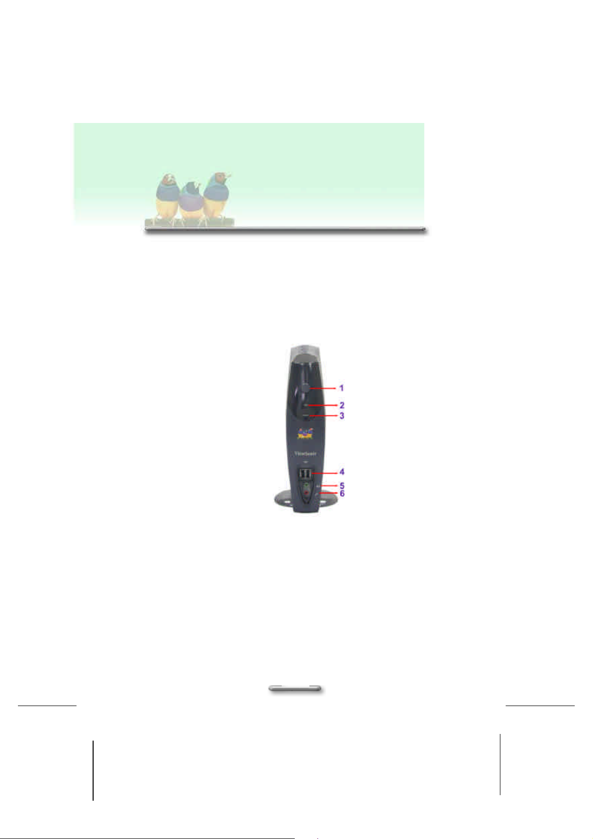
Figure 1-1. The front panel of ViewBox 100.NET Client
Refer to the following illustrations to identify components located at the front panel of
the ViewBox 100, as shown in Figure 1-1.
1. Power Button:
Pressing this button enables you to power on/off the system.
2. Power On/Off Indicator:
The indicator lights up when the system power is on.
9
Page 10

Chapter 2 Getting Started
3. USB Port x 2:
Two USB ports allow input and output devices to be easily attached to the
ViewBox 100. Please plug in your USB devices in these two ports.
4. Line-out/Speaker Jack:
This jack is connected to your audio device that receives the audio output of the
system, such as speakers, or headphones.
5. Microphone Jack:
This jack is connected to your microphone.
10
Page 11
Chapter1 Getting Started
Rear Panel
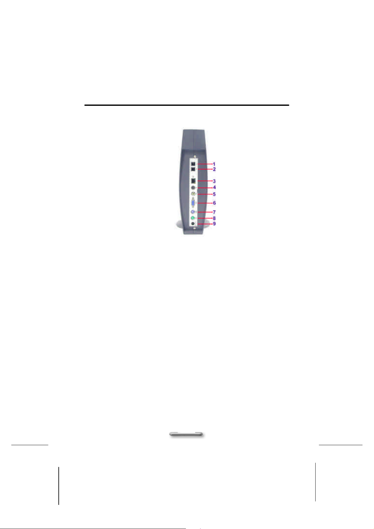
Figure 1-2. The rear panel of ViewBox 100
The rear panel of the ViewBox 100 is where you connect power, peripheral devices
such as a PS/2, input devices and output devices such as the display monitor. Please
refer to the above figures for the location of each of the rear components, as shown in
Figure 1-2.
1. Wall Line Jack (optional): (HPNA Configuration)
This jack is connected to the phone line.
2. Phone Jack (optional): (HPNA Configuration)
This jack is connected to the telephone.
3. RJ45 LAN connector:
For connecting with your LAN to access the network services or surf the Internet.
4. S-Video Connector:
The ViewBox System has a video port that that provides composite video output
to a PAL or NTSC video monitor or VCR.
5. AV Connector:
The ViewBox 100 also provides a AV connector for transmitting video data to a
TV.
11
Page 12
Chapter 2 Getting Started
6. Monitor/VGA Connector (blue):
Please connect this port with your monitor.
7. PS/2 Keyboard Connector (purple):
Please plug in your PS/2 keyboard into this connector.
8. PS/2 Mouse connector (green):
Please plug in your PS/2 mouse cable here.
9. Power Adapter jack:
This jack is connected to the AC Adapter (provided).
Connecting Your Peripheral Devices
Connecting a Monitor
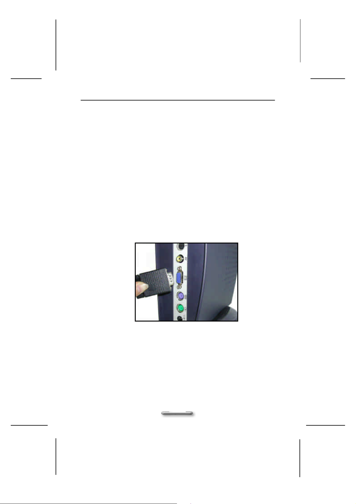
Connect the monitor cable to the VGA connector on the rear panel of the ViewBox 100.
If the connector has retaining screw, be sure to tighten them, as shown in Figure 1-3.
Figure 1-3. Connecting a monitor via VGA Connector
Connecting a USB Keyboard
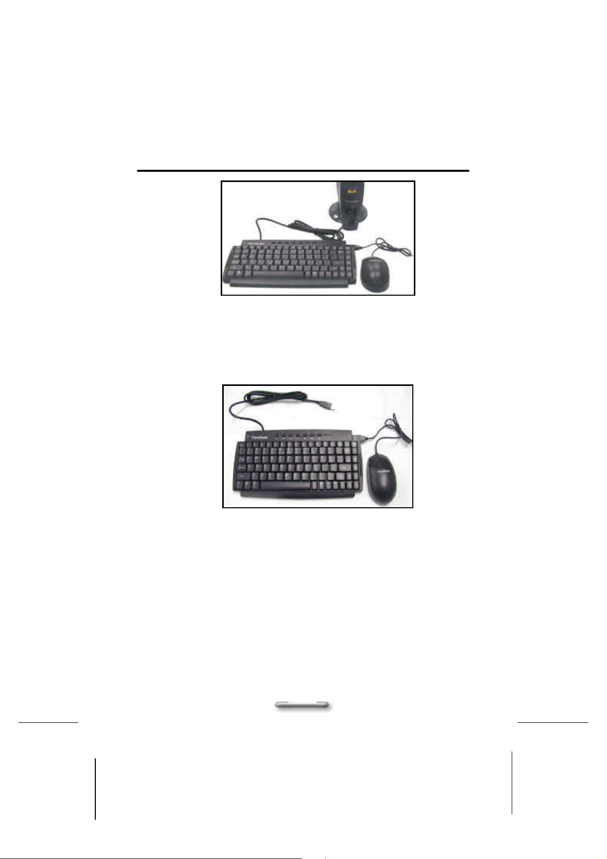
Plug the USB Keyboard cable connector into the USB port on the front panel of your
ViewBox System, as shown in Figure 1-4.
12
Page 13
Chapter1 Getting Started
Figure 1-4. Connecting a USB Keyboard via the USB connector
Connecting a USB Mouse
Plug the USB Mouse cable connector into the USB mouse connector on the USB
Keyboard as shown in Figure 1-4 and Figure 1-5.
Figure 1-5. Connecting a USB Mouse via USB Keyboard
NOTE:
There are two standard PS/2 keyboard and mouse connectors built-in on the rear
panel of the ViewBox 100. You can also plug the standard PS/2 keyboard and mouse
cable connectors into these connectors.
13
Page 14
Chapter 2 Getting Started
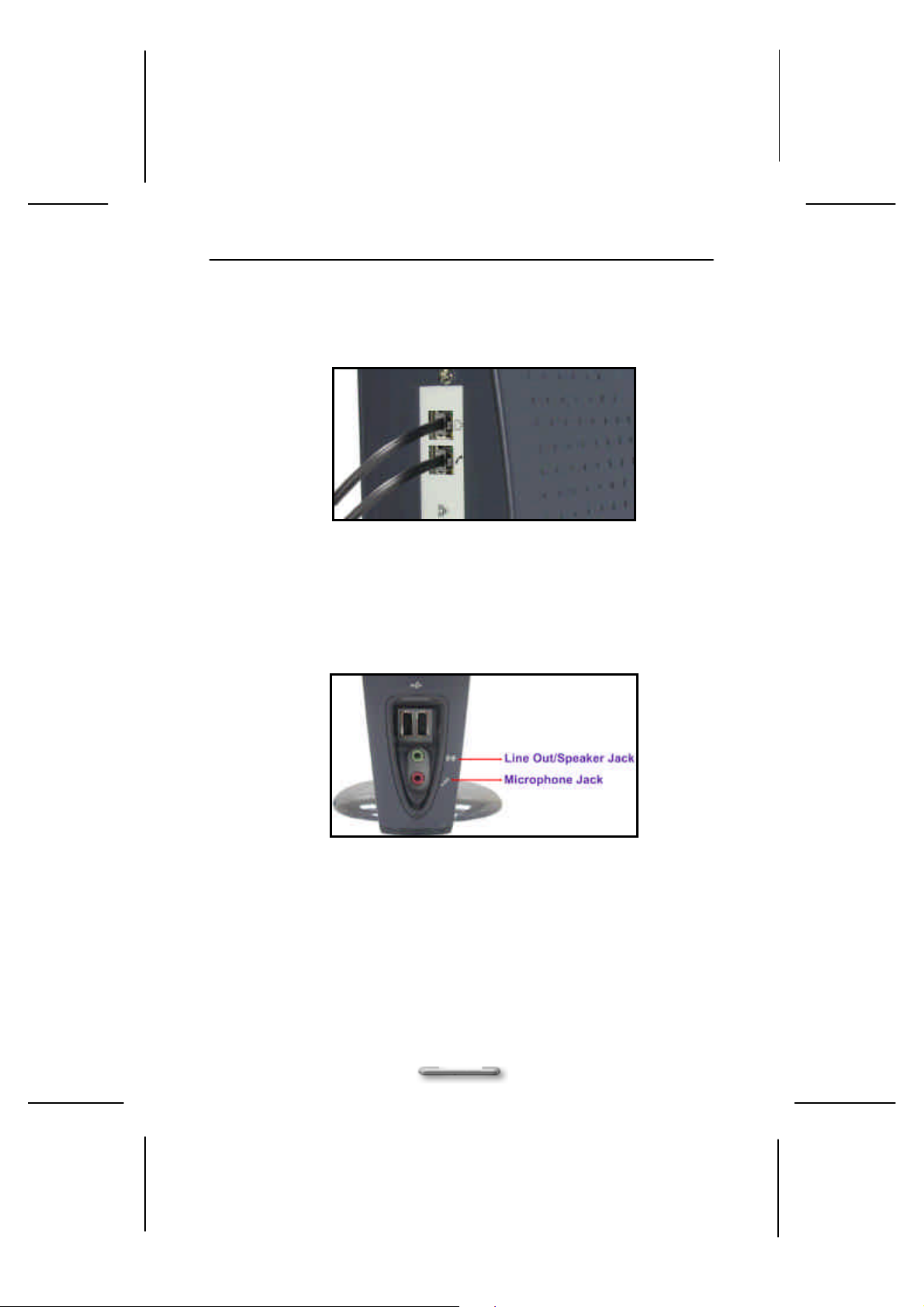
Connecting HPNA Cables (Optional)
Connect the phone and wall lines to the HPNA (Home Personal Network Assistant)
card connectors, as shown in Figure 1-6.
Figure 1-6. Connecting the HPNA cables via Wall Line and Phone Jack
Connecting Audio Cables
ViewBox 100 has two integrated audio controller jacks (Line-out and Microphone
jack) . You can connect a microphone to the microphone jack and a speaker or
headphone to the Line-out jack, as shown in Figure 1-7.
Figure 1-7. Connecting Audio devices via Line-out or Microphone Jack.
14
Page 15
Chapter1 Getting Started
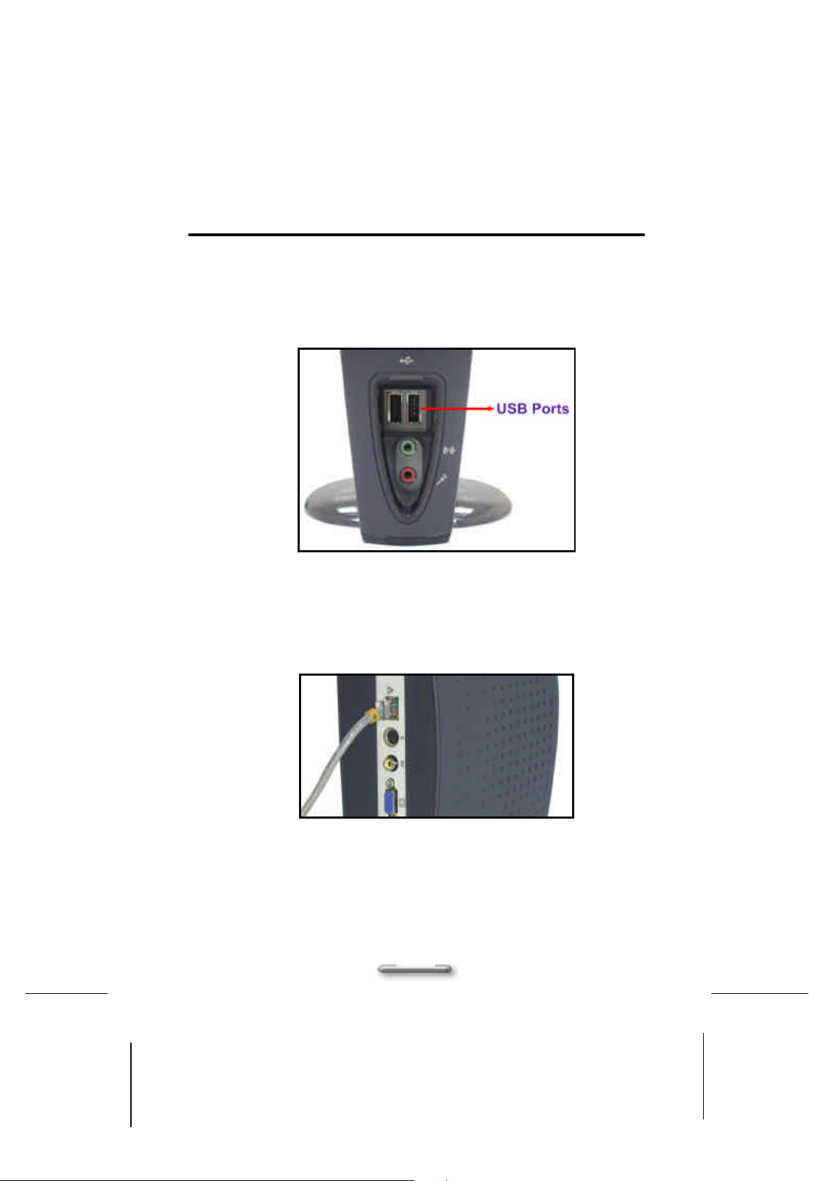
Connecting USB Devices
If you have the USB devices, you can connect these to the USB connectors. To
connect a USB device to the USB connector, plug the USB device cable connector
into the USB connector of your ViewMate 100, as shown in Figure 1-8.
Figure 1-8. Connecting USB devices via USB Connector
Connecting the Network
If you are under a LAN environment, you can connect to the network via the Ethernet
connector to the Hub, as shown in Figure 1-9.
Figure 1-9. Connecting to the network (LAN)
15
Page 16
Chapter 2 Getting Started
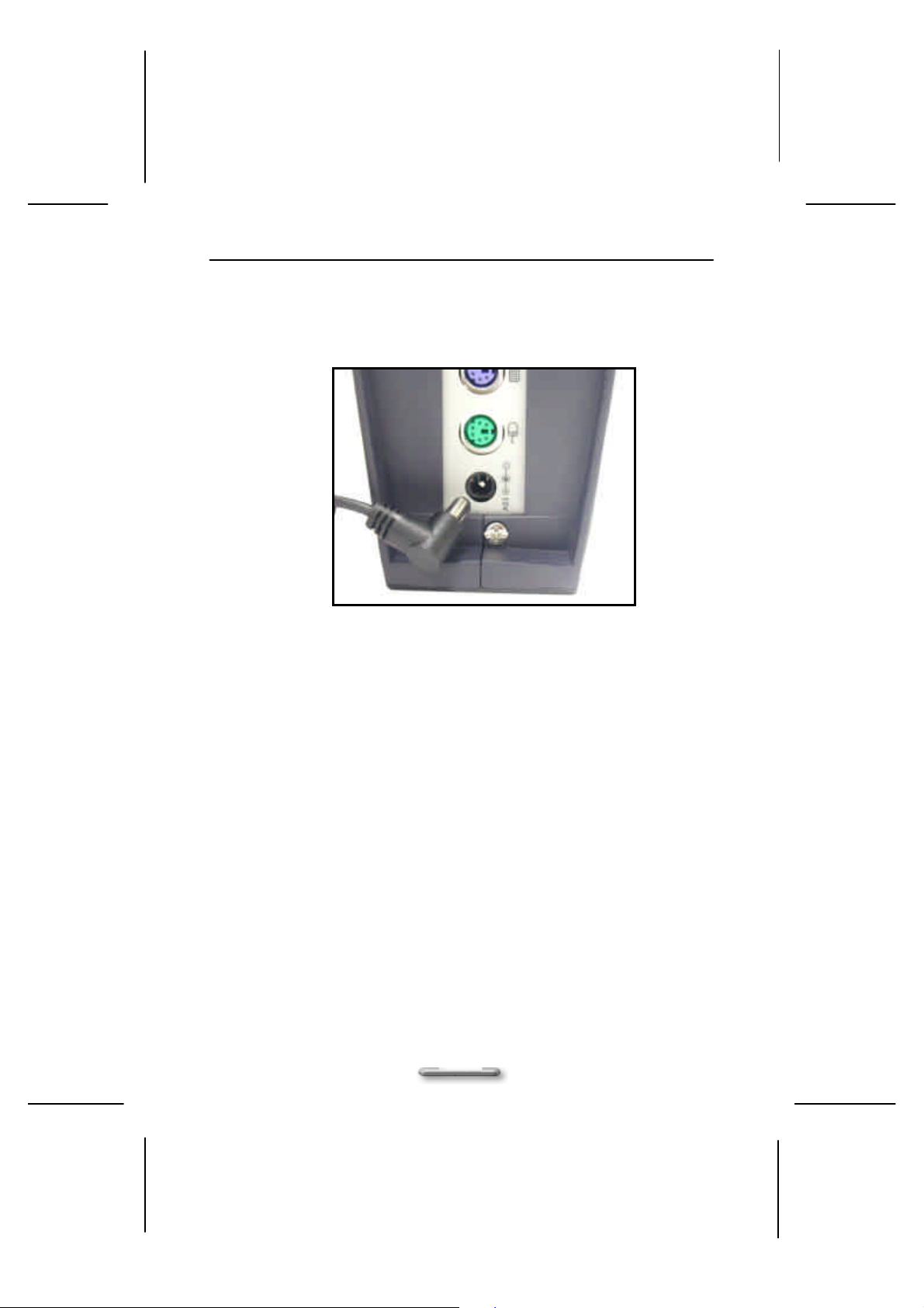
Connecting the Power Adapter
Plug one end of the power adapter to the power adapter jack, and then the other end
of the power cord into the wall outlet, as shown in Figure 1-10.
Figure 1-10. Connecting to the Power Adapter
16
Page 17
Chapter3 Other Information
OOtthheerr IInnffoorrm
Specification
Dimension
Chassis
Bezel
Drive Bay
CPU Heatsink
Expansion
Back Panel
225 (L) x 233.5(H) x 38 (W) mm (w/plastic)
? base Metal case
? Keylock
? EMI Clip
? Vertical standing
? Horizontal position is possible
? Materials
? Injection Color
? Texture
? Every Plastic Component must
? HDD (Storage)
? CD ROM
? FDD
? Active Heatsink
? Passive Heatsink
? IO Slot in Back ? No
? Serial Port
? Parallel Port
? PS2
? RJ45 for LAN
? RJ11 for HPNA
? Audio Jack
? VGA
? AV-out
? S-Connector
? DFP/DVI
? 12 DC in
be marked with
CChhaapptteerr 33
maattiioonn
? Use 0.8mm thick
? No
? Yes
? Yes
? Yes
? ABS and
? Pantone 293U or other
? Model-Tech MT11020 Vapor Hone
? Material type, Flammability (if
applicable), recyclable logo, P/N
? No
? No
? No
? No
? No
? No
? No
? 2
? 1
? 2 (on HPNA card)
? No
? 1
? 1
? 1
? No
? 1
17
Page 18

Chapter 3 Other Information
Front Panel
LED spec.
Power Supply
Wireless LAN
Certification
All specifications listed above are subject to change without prior notice.
? USB
? Audio Jack
? 1394 connector
? Power Button
? Power LED
? LAN LED in connector
? Vendor
? Watts
? AMBIT ? Mini PCI 802.1b
? EMC
? Safety
? WIN CE
? 2
? 2 (for Headphone-out and MIC-in)
? No
? Yes
? Green Always on/off: Power on/off
? Upper: Green blinking for active.
? Hipro and Delta
? 12V/36W
? FCC/CE/
? UL/CUL or CAS/TUV
Lower: Orange for link.
Trouble Shooting
Question: ViewBox 100 no power.
Solution:
Question: Power on but no screen image.
Solution:
Question: ViewBox 100 locks up when running applications, or runs slowly.
Solution:
Question: Keyboard Error
Solution:
? Make sure power button (or switch) is ON.
? Make sure AC power cord is securely connected to the back of the
monitor and to a power outlet.
? Plug another electrical device (like a radio) into the power outlet to verify
that the outlet is supplying proper voltage.
? Make sure the video cable supplied with the monitor is tightly secured to
the video output port on the back of the computer. If the other end of the
video cable is not attached permanently to the monitor, tightly secure it to
the monitor.
? ViewBox 100 is locked up. Close some applications those are not in use,
if this doesn’t work, try to restart the ViewBox 100 by turning power off
and on. Be sure to save your data before you restart the system.
? Check the connections between the keyboard and the ViewBox 100.
18
Page 19

Question: Screen display is small
Solution:
Question: No Sound
Solution:
? Use a lower vertical refresh rate. If the refresh rate is too high, some
monitors will compensate by making the image smaller.
? Be certain the power is on for the speakers. Make sure that the unit is
hooked up to an AC adapter and the power button is ON.
? Use only the AC adapter provided. Check the connections between the
computer and the speakers.
? Be certain there is output from the sound device. Remove the plug from
the sound device, turn the speakers to maximum volume and touch the
tip of the plug. You should hear a hum or buzz coming from the
speakers. If you do, the speakers are working. Check the sound device
to locate the problem.
? Are headphones plugged into the headphone jack? Headphones plugged
into the speaker's headphone jack will block sound from the speakers.
Remove the headphones to restore sound to the speakers.
Chapter3 Other Information
19
Page 20

Chapter 3 Other Information
Customer Support
For the most expedient answer to your question, do the following:
1. Check “Trouble Shooting” on the previous section.
2. For assistance contact your reseller.
3. For further assistance see the contact information listed below.
If contact information for your country or region is not listed below, ask your reseller to
refer you to a service center.
NOTE:
You will need to provide the serial number (on the back of the product).
Country/Region T = Telephone; F = Fax Email
United States
Canada
United Kingdom
Europe, Middle East,
Baltic countries, and
North Africa
Australia
New Zealand
Singapore/Southeast
Asia
Other Asia/Pacific
countries and Indian
Peninsula
South Africa T: 27-11-314-0002
.
T: (800) 688-6688
F: (909) 468-1202
T: (800) 688-6688
F: (909) 468-1202
T: 0800 833 648
F: 0044 (0)1293 643910
T: 0044 (0)1293 643900
F: 0044 (0)1293 643910
800 880 818
T: 64- 3 - 366-1135
F: 64-3-366-7006
T: 65-273-4018
F: 65-273-1566
T: 886-2-2248-4072
F: 886-2-2249-1751
F: 27-11-314-0002
20
Page 21
Chapter3 Other Information
miitteedd
LLiim
AAppppeennddiixx
Waarrrraannttyy
W
ViewBox 100
What the warranty covers:
ViewSonic® warrants its products to be free from defects in material and workmanship during the warranty period.
If a product proves to be defective in material or workmanship during the warranty period, ViewSonic® will at its
sole option repair or replace the product with a like product. Replacement product or parts may include
remanufactured parts or components.
How long the warranty is effective:
ViewBox, are warranted for one(1) years for all parts and for all labor from the date of the first consumer purchase.
Who the warranty protects:
This warranty is valid only for the first consumer purchaser.
What the warranty does not cover:
1. Any product on which the serial number has been defaced, modified or removed.
2. Damage, deterioration or malfunction resulting from:
a. Accident, misuse, neglect, fire, water, lightning, or other acts of nature, unauthorized product
modification, or failure to follow instructions supplied with the product.
b. Repair or attempted repair by anyone not authorized by ViewSonic.
c. Any damage of the product due to shipment.
d. Removal or installation of the product.
e. Causes external to the product, such as electronic power fluctuations or failure.
f. Use of supplies or parts not meeting ViewSonic's specifications.
g. Normal wear and tear.
h. Any other cause which does not relate to a product defect.
3. Removal, installation, and set-up service charges.
How to get service:
1. For information on obtaining warranted service, call ViewSonic Customer Support. See the back cover of
this user's manual. You will need to provide your projector's serial number.
2. To obtain warranted service, you will be required to provide (a) the original dated sales slip, (b) your name,
(c) your address, (d) a description of the problem, and (e) the serial number of the product.
3. Take or ship the product prepaid in the original container to your ViewSonic dealer, any ViewSonic service
center or ViewSonic.
4. For additional information or the name of the nearest ViewSonic service center, contact your ViewSonic
dealer or ViewSonic.
Limitation of implied warranties:
THERE ARE NO WARRANTIES, EXPRESSED OR IMPLIED, WHICH EXTEND BEYOND THE DESCRIPTION
CONTAINED HEREIN INCLUDING THE IMPLIED WARRANTY OF MERCHANTABILITY AND FITNESS FOR A
PARTICULAR PURPOSE.
Exclusion of damages:
VIEWSONIC'S LIABILITY IS LIMITED TO THE COST OF REPAIR OR REPLACEMENT OF THE PRODUCT.
VIEWSONIC SHALL NOT BE LIABLE FOR:
1. DAMAGE TO OTHER PROPERTY CAUSED BY ANY DEFECTS IN THE PRODUCT, DAMAGES BASED
UPON INCONVENIENCE, LOSS OF USE OF THE PRODUCT, LOSS OF TIME, LOSS OF PROFITS,
LOSS OF BUSINESS OPPORTUNITY, LOSS OF GOODWILL, INTERFERENCE WITH BUSINESS
RELATIONSHIPS, OR OTHER COMMERCIAL LOSS, EVEN ID ADVISED OF THE POSSIBILITY OF
SUCH DAMAGES.
2. ANY OTHER DAMAGES, WHETHER INCIDENTAL, CONSEQUENTIAL OR OTHERWISE.
3. ANY CLAIM AGAINST THE CUSTOMER BY ANY OTHER PARTY.
Effect of state law:
21
Page 22

Chapter 3 Other Information
This warranty gives you specific legal rights, and you may also have other rights which vary from state to state.
Some states do not allow limitations on implied warranties and/or do not allow the exclusion of incidental or
consequential, so the above limitations and exclusions may not apply to you.
Sales outside the U.S.A.:
For ViewSonic products sold outside of the U.S.A., contact your ViewSonic dealer for warranty information and
services.
22
 Loading...