

Page 1

Service Manual
ViewSonic VG710b/s1
Model No. VLCDS23719-4W/-5W
17” Color TFT LCD Display
ViewSonic
(VG710s/b-1_SM_718 Rev. 1b Aug. 2004)
381 Brea Canyon Road, Walnut, California 91789 USA - (800) 888-8583
Page 2
Copyright
Copyright
2004 by ViewSonic Corporation. All rights reserved. No part of this publication may be
¤
reproduced, transmitted, transcribed, stored in a retrieval system, or translated into any language or
computer language, in any form or by any means, electronic, mechanical, magnetic, optical, chemical,
manual or otherwise, without the prior written permission of ViewSonic Corporation.
Disclaimer
ViewSonic makes no representations or warranties, either expressed or implied, with respect to the
contents hereof and specifically disclaims any warranty of merchantability or fitness for any particular
purpose. Further, ViewSonic reserves the right to revise this publication and to make changes from time
to time in the contents hereof without obligation of ViewSonic to notify any person of such revision or
changes.
Trademarks
Optiquest is a registered trademark of ViewSonic Corporation.
ViewSonic is a registered trademark of ViewSonic Corporation.
All other trademarks used within this document are the property of their respective owners.
1a
1b
DCN Number ECR Number
26/02/04
12/08/04
Revision History
Documents Number
3601
4645
4499
Initial Release
ECR Change Genesis-gm5120 Scalar
Add CMO Panel Sources
Description of Changes EditorRevision SM Editing Date
A. Lu
A. Lu
ViewSonic Corporation Confidential
i
-
Do Not Copy VG710b/s-1
Page 3

TABLE OF CONTENTS
1. Precautions and Safety Notices
2. Specification
3. Front Panel Function Control Description
4. Circuit Description
5. Adjusting Procedure
6. Trouble Shooting Flow Chart
7. Recommended Spare Parts List
8. Exploded Diagram And Spare Parts List
9. Block Diagram
10. Schematic Diagrams
11. PCB Layout Diagrams
1
5
8
14
16
39
43
53
64
65
71
ViewSonic Corporation Confidential
ii
-
Do Not Copy VG710b/s-1
Page 4

1. Precautions and Safety Notices
1. Appropriate Operation
(1) Turn off the product before cleaning.
(2) Use only a dry soft cloth when cleaning the LCD panel surface.
(3) Use a soft cloth soaked with mild detergent to clean the display housing.
(4) Use only high quality and safety approved AC/DC power adapter.
(5) Disconnect the power plug from AC outlet if the product is not used for a long period of time.
(6) If smoke, abnormal noise, or strange odor is present, immediately switch the LCD display off.
(7) Do not touch the LCD panel surface with sharp or hard objects.
(8) Do not place heavy objects on the LCD display, video cable, or power cord.
(9) Do not use abrasive cleaners, waxes or solvents for your cleaning.
(10) Do not operate the product under the following conditions:
- Extremely hot, cold or humid environment.
- Areas susceptible to excessive dust and dirt.
- Near any appliance generating a strong magnetic field.
- Place in direct sunlight.
2. Caution
No modification of any circuit should be attempted. Service work should only be performed after you are thoroughly familiar
with all of the following safety checks and servicing guidelines.
3. Safety Check
Care should be taken while servicing this LCD display. Because of the high voltage used in the inverter circuit, the voltage is
exposed in such areas as the associated transformer circuits.
4. Power Supply Requirements
The external power converter for this display utilizes AC and DC cords, AC cord is detachable, but DC cord is permanently
attached. Any attempt to replace another adapter could result in serious problem on the display.
5. LCD Module Handling Precautions
5.1 Handling Precautions
(1) Since front polarizer is easily damaged, pay attention not to scratch it.
(2) Be sure to turn off power supply when inserting or disconnecting from input connector.
(3) Wipe off water drop immediately. Long contact with water may cause discoloration or spots.
(4) When the panel surface is soiled, wipe it with absorbent cotton or other soft cloth.
(5) Since the panel is made of glass, it may break or crack if dropped or bumped on hard surface.
(6) Since CMOS LSI is used in this module, take care of static electricity and insure human earth when handling.
(7) Do not open nor modify the Module Assembly.
(8) Do not press the reflector sheet at the back of the module to any directions.
(9) In case if a Module has to be put back into the packing container slot after once it was taken out from the
container, do not press the center of the CCFL Reflector edge. Instead, press at the far ends of the CFL
Reflector edge softly. Otherwise the TFT Module may be damaged.
(10) At the insertion or removal of the Signal Interface Connector, be sure not to rotate nor tilt the Interface
Connector of the TFT Module.
ViewSonic Corporation Confidential
1
-
Do Not Copy VG710b/s-1
Page 5

(11) After installation of the TFT Module into an enclosure (LCD monitor housing, for example), do not twist nor
bend the TFT Module even momentary. At designing the enclosure, it should be taken into consideration that
no bending/twisting forces are applied to the TFT Module from outside. Otherwise the TFT Module may be
damaged.
(12) Cold cathode fluorescent lamp in LCD contains a small amount of mercury. Please follow local ordinances or
regulations for disposal.
(13) Small amount of materials having no flammability grade is used in the LCD module. The LCD module should
be supplied by power complied with requirements of Limited Power Source (IEC60950 or UL1950), or be
applied exemption.
(14) The LCD module is designed so that the CFL in it is supplied by Limited Current Circuit (IEC60950 or
UL1950). Do not connect the CFL in Hazardous Voltage Circuit.
ViewSonic Corporation Confidential
2
-
Do Not Copy VG710b/s-1
Page 6
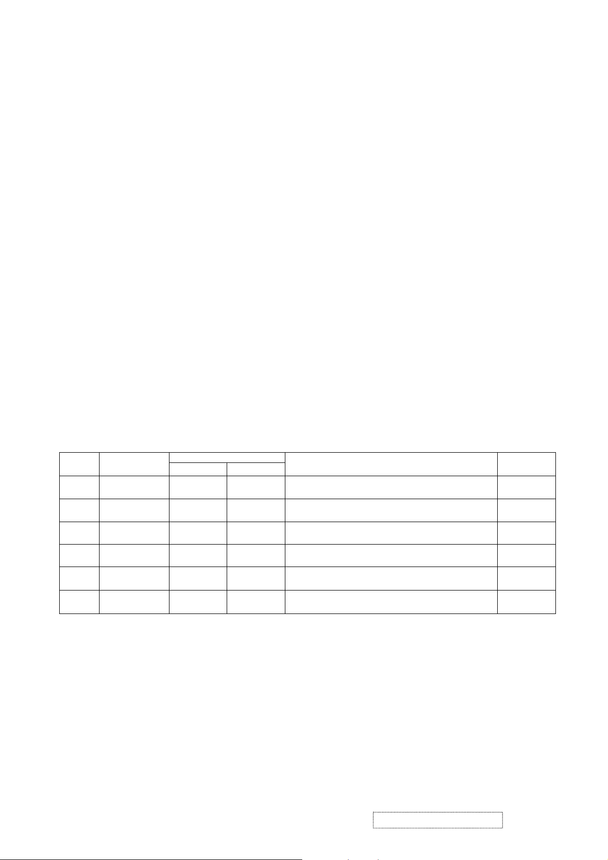
5.2 Handling and Placing Methods
Correct Methods:
Only touch the metal frame of the LCD panel or the front
cover of the monitor. Do not touch the surface of the
polarizer.
Incorrect Methods:
Surface of the LCD panel is pressed by fingers and that
may cause “Mura.”
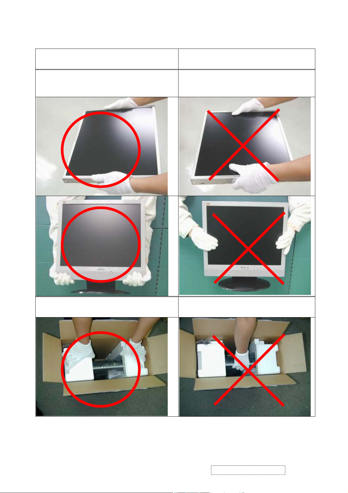
Take out the monitor with cushions
Taking out the monitor by grasping the LCD panel. That
may cause “Mura.”
ViewSonic Corporation Confidential
3
-
Do Not Copy VG710b/s-1
Page 7
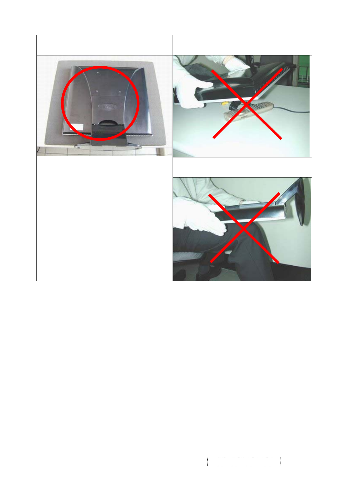
Place the monitor on a clean and soft foam pad.
Placing the monitor on foreign objects. That could
scratch the surface of the panel or cause “Mura.”
The panel is placed facedown on the lap. That
may cause “Mura.”
ViewSonic Corporation Confidential
4
-
Do Not Copy VG710b/s-1
Page 8
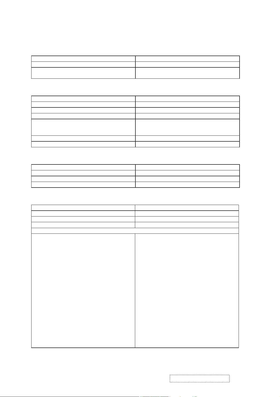
2. Specification
1. General Requirements
General Specifications
Test Resolution & Frequency “1280 x 1024” @ 60Hz
Test Image Size Full Size
Contrast and Brightness Controls Factory Default:
Contrast = 50%, Brightness = 100%
2. Signal Interface
Video Interface
Analog Input Connector DB-15 (Analog)
Digital Input Connector DVI-D (Digital)
Default Input Connector Defaults to the first detected input
Video Cable Connector DB-15 Pin out Compliant DDC 1/2B.
Video Signals
Video Impedance 75 Ohms (Analog), 100 Ohms (Digital)
Exclusions Not compatible with interlaced video.
3. Power
Power Supply
External Power Supply Part Number: LSE 0107A1240
Input Voltage Range 90 to 264 VAC
Over Voltage Protection 12.7~18V FULL LOAD
Power Dissipation 36 WATTS (TYP)
4. Electrical Requirements
1. Video RGB (Analog)
2. TMDS (Digital)
Separate Sync
Horizontal / Vertical Frequency
Horizontal Frequency 30 – 82 kHz
Vertical Refresh Rate 50 – 85 HZ
Maximum Pixel Clock 135 MHz
Primary Preset “1280 x 1024” @ 60Hz
Look up table timing
<<Analog>>
1. 640 x 350 @ 70Hz, 31.5kHz
2. 640 x 480 @ 60Hz, 31.5kHz
3. 640 x 480 @ 67Hz, 35.0kHz
4. 640 x 480 @ 75Hz, 37.5kHz
5. 640 x 480 @ 72Hz, 37.9kHz
6. 640 x 480 @ 85Hz, 43.27kHz
7. 720 x 400 @ 70Hz, 31.5kHz
8. 800 x 600 @ 56Hz, 35.1kHz
9. 800 x 600 @ 60Hz, 37.9kHz
10. 800 x 600 @ 75Hz, 46.9kHz
11. 800 x 600 @ 72Hz, 48.1kHz
12. 800 x 600 @ 85Hz, 53.7kHz
13. 832 x 624 @ 75Hz, 49.7kHz
14. 1024 x 768 @ 60Hz, 48.4kHz
15. 1024 x 768 @ 70Hz, 56.5kHz
16. 1024 x 768 @ 72Hz, 58.1kHz
17. 1024 x 768 @ 75Hz, 60.0kHz
18. 1024 x 768 @ 85Hz, 68.67kHz
19. 1280 x 1024 @ 60Hz, 63.4kHz
20. 1280 x 1024 @ 75Hz, 79.97kHz
<<Digital>>
640 x 350 @ 70Hz, 31.5kHz
640 x 400 @ 60Hz, 31.5kHz
640 x 480 @ 60Hz, 31.5kHz
640 x 480 @ 75Hz, 37.5kHz
640 x 480 @ 72Hz, 37.9kHz
640 x 480 @ 85Hz, 43.27kHz
720 x 400 @ 70Hz, 31.5kHz
800 x 600 @ 56Hz, 35.1kHz
800 x 600 @ 60Hz, 37.9kHz
800 x 600 @ 75Hz, 46.9kHz
800 x 600 @ 72Hz, 48.1kHz
800 x 600 @ 85Hz, 53.7kHz
1024 x 768 @ 60Hz, 48.4kHz
1024 x 768 @ 70Hz, 56.5kHz
1024 x 768 @ 72Hz, 58.1kHz
1024 x 768 @ 75Hz, 60.0kHz
1024 x 768 @ 85Hz, 68.67kHz
1280 x 1024 @ 60Hz, 63.4kHz
ViewSonic Corporation Confidential
5
-
Do Not Copy VG710b/s-1
Page 9
Changing Modes
Maximum Mode Change Blank Time for image
stability. Note:
1) Excluding “Auto Adjust” time
2) Under DOS mode (640 x 350, 720 x 400 & 640 x
Under 5 seconds (Maximum)
1 seconds (Typ.) for recognized timings
1-2 seconds (Typ.) for unrecognized timing
.
400), there is no “Auto Adjust” feature.
3) The monitor needs to do “Auto Adjust” the first
time a new mode is detected.
5. Audio
Speaker Specification
Line input connection 3.5 mm stereo jack
Line input signal 1.0 Vrms
Line input impedance 10 kOhm
Maximum power output (Electric) 3 W @ < 5 % DISTORTION
Signal to Noise Ratio 72 dB
Frequency response 400 Hz – 20 kHz
Distortion < 5 % THD (@1kHz),
6. LCD Panel
Panel Characteristics
Panel Type “LG LM170E01-A5”
Type “TFT ACTIVE MATRIX
Active Size 337.9 (H) x 270.3 (V)
Pixel Arrangement RGB Vertical Stripe
Pixel Pitch 0.264 mm
Glass Treatment Anti Glare (Hard coating 3H)
# of Backlights 4 CCFL edge-light (2 top / 2 bottom)
Backlight Life 50,000 Hours (minimum)
Panel Performance
Luminance –
Condition:
250 cd/m
200 cd/m2 (minimum after 30-minute warm-up)
2
(typ. after 30-minute warm-up)
CT = 6500K, Contrast = Max,
Brightness = Max
Brightness Uniformity ∆L5=Max 1.3 ∆L5= Maximum Luminance/
Minimum Luminance
Contrast Ratio 450:1 (typ.), 300:1 (minimum)
Color Depth 16 Million colors (8 bit panel)
Viewing Angle (Horizontal) 140 degrees @ CR>10, 160 degrees @ CR>5
Viewing Angle (Vertical) 120 degrees @ CR>10, 140 degrees @ CR>5
Response Time
10%-90% @ Ta=25°C
16 ms (Tr= 2 ms, Tf = 14 ms) (typ.)
30 ms (Tr= 6 ms, Tf = 24 ms) (maximum)
Note: The 2nd source of LCD panel is “AU M170EN05.”
7. Mechanical
Dimensions
Width 378 mm
Height 405 mm
Depth 177 mm
Depth (Head Only) 50 mm
Monitor Weight 5.3 kg / 11.66 lbs
ViewSonic Corporation Confidential
6
-
Do Not Copy VG710b/s-1
Page 10
Ergonomics
Tilt Up
20 DEGREES MINIMUM
Tilt Down -5 degrees
8. Environmental
Environmental Conditions
Operating Temperature 0°C to +40°C
Storage Temperature -20°C to +60°C
Operating Relative Humidity 20% to 80% RH Non-Condensing
Storage Relative Humidity 5% to 90% RH Non-Condensing
Operating Altitude 0 to +3,000 meters
Storage Altitude 0 to +12,000 meters
ViewSonic Corporation Confidential
7
-
Do Not Copy VG710b/s-1
Page 11
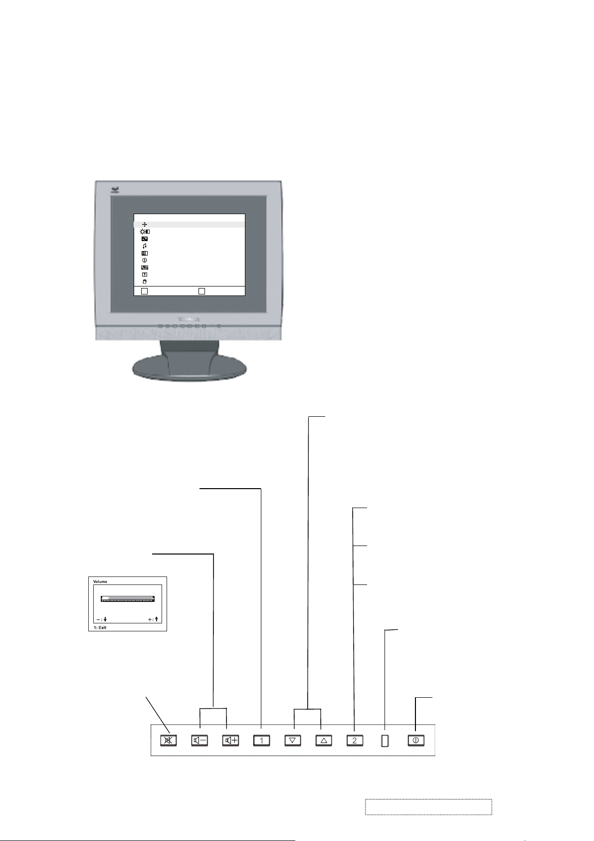
3. Front Panel Function Control Description
Adjusting the Screen Image
Use the buttons on the front control panel to display and adjust the OnView
®
controls which display on the screen. The OnView controls are explained at the
top of the next page and are defined in “Main Menu Controls” on page10.
MAIN
MENU
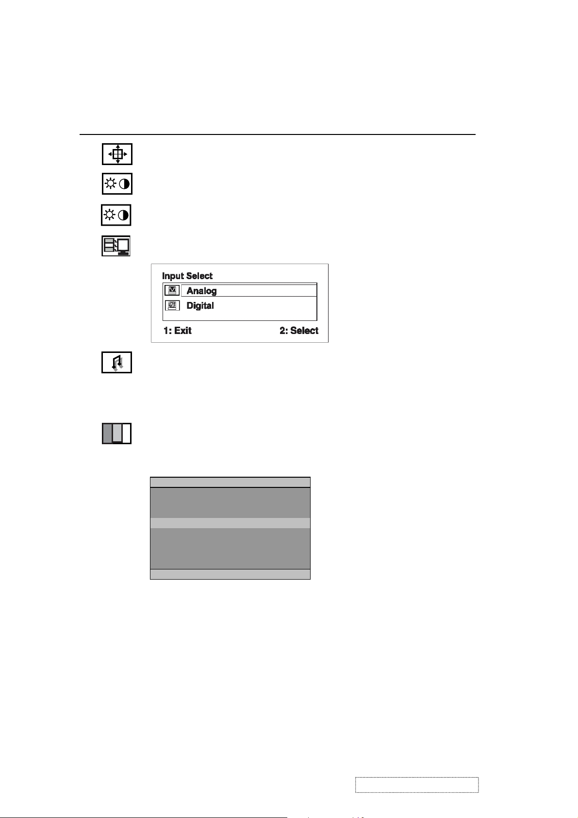
AUTO IMAGE ADJUST
CONTRAST/BRIGHTNESS
INPUT SELECT
AUDIO MENU
COLOR ADJUST
INFORMATION
MANUAL IMAGE ADJUST
SETUP MENU
MEMORY RECALL
:EXIT :SELECT
1
2
Speaker Speaker
Main Menu with OnView controls
Front Control Panel shown
below
Scrolls through menu options and
adjusts the displayed control.
Also a shortcut to display the
Contrast adjustment control
screen.
Displays the Main Menu
or exits the control screen
and saves adjustments
Decreases or
increases volume
Audio Mute button
turns the sound off.
Displays the control
screen for the highlighted
control.
Also toggles between two
controls on some
screens.
Also a shortcut to toggle
between analog and
digital connections.
Power light
Green = ON
Orange = Power
Saving
Power
On/Off
ViewSonic Corporation Confidential
8
-
Do Not Copy VG710b/s-1
Page 12
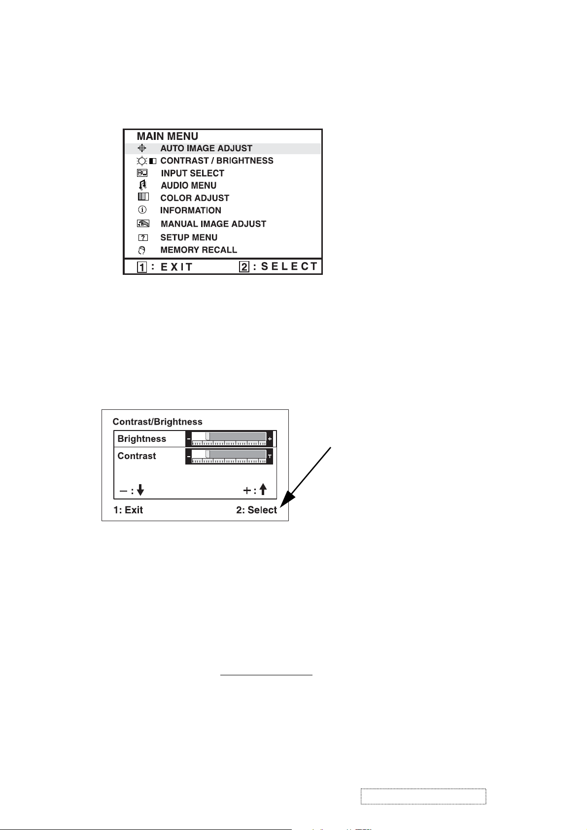
Do the following to adjust the screen image:
To display the Main Menu, press button [1].
1
NOTE:
All OnView menus and adjustment screens disappear automatically
after about 15 seconds. This is adjustable through the OSD timeout setting in the
setup menu.
2
To select a control you want to adjust, press ▲ or ▼ to scroll up or down the
Main Menu.
3
After the control is selected, press button [2]. A control screen like the one
shown below appears.
The command line at the
bottom of the control screen
tells what to do next from this
screen. You can toggle
between control screens,
adjust the selected option, or
exit the screen.
4
To adjust the control, press the up ▲ or down ▼ buttons.
5
To save the adjustments and exit the menu, press button [1]
twice
.
The following tips may help you optimize your display:
• Adjust your computer's graphic card so that it outputs a video signal 1280 x
1024 @ 60Hz to the LCD display. (Look for instructions on "changing the
refresh rate" in your graphic card's user guide.)
• If necessary, make small adjustments using H POSITION and V POSITION
until the screen image is completely visible
. (The black border around the
edge of the screen should barely touch the illuminated "active area" of the
LCD display.)
ViewSonic Corporation Confidential
9
-
Do Not Copy VG710b/s-1
Page 13
Main Menu Controls
Adjust the menu items shown below by using the up ▲ and down ▼ buttons.
Control Explanation
Auto Image Adjust
sizes and centers the screen image
automatically.
Contrast
adjusts the difference between the image background
(black level) and the foreground (white level).
Brightness
Input Select
adjusts background black level of the screen image.
toggles between inputs if you have more than one
computer.
Audio Adjust
Volume
increases the volume, decreases the volume, and
mutes the audio.
temporarily silences audio output.
Mute
Color Adjust
color temperatures and
green (G), and blue (B) separately. The factory setting for this
product is 6500K (6500 Kelvin).
provides several color adjustment modes: preset
RGB
which allows you to adjust red (R),
Color Adjust
sRGB
9300K
˙6500K
5400K
5000K
User Color
1:EXIT 2:SELECT
sRGB
— sRGB is quickly becoming the industry standard for color
management, with support being included in many of the latest
applications. Enabling this setting allows the LCD display to
more accurately display colors the way they were originally
intended. Enabling the sRGB setting will cause the Contrast and
Brightness adjustments to be disabled.
9300K
in most office settings with fluorescent lighting).
6500K
richer red.
5400K
ViewSonic Corporation Confidential
5000K
color.
— Adds blue to the screen image for cooler white (used
— Adds red to the screen image for warmer white and
— Adds green to the screen image for a darker color.
— Adds blue and green to the screen image for a darker
10
-
Do Not Copy VG710b/s-1
Page 14
Control Explanation
User Color
and blue (B)
1
To select color (R, G or B) press button [2].
2
To adjust selected color, press ▲ or ▼.
Important
— Individual adjustments for red (R), green (G),
.
: If you select RECALL from the Main Menu when
the product is set to a Preset Timing Mode, colors return to the
6500K factory preset.
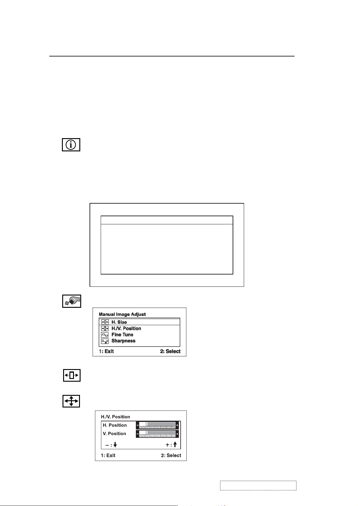
Information
displays the timing mode (video signal input)
coming from the graphics card in your computer, the LCD
model number, the serial number, and the ViewSonic website
URL. See your graphic card’s user guide for instructions on
changing the resolution and refresh rate (vertical frequency).
NOTE:
VESA 1280 x 1024 @ 60Hz (recommended) means
that the resolution is 1280 x 1024 and the refresh rate is 60
Hertz.
Information:
H. Frequency: XX kHz
V. Frequency: XX Hz
Resolution XXXXXXXXX
Pixel Clock: XXX MHz
Serial Number: XXXXXXXXXXX
Model Number: XXXXXXXXXXX
www.ViewSonic.com 1: Exit
Manual Image Adjust Sub-menu
H. Size (Horizontal Size)
H./V. Position (Horizontal/Vertical Position)
adjusts the width of the screen image.
image left or right and up or down.
moves the screen
ViewSonic Corporation Confidential
11
-
Do Not Copy VG710b/s-1
Page 15
Control Explanation
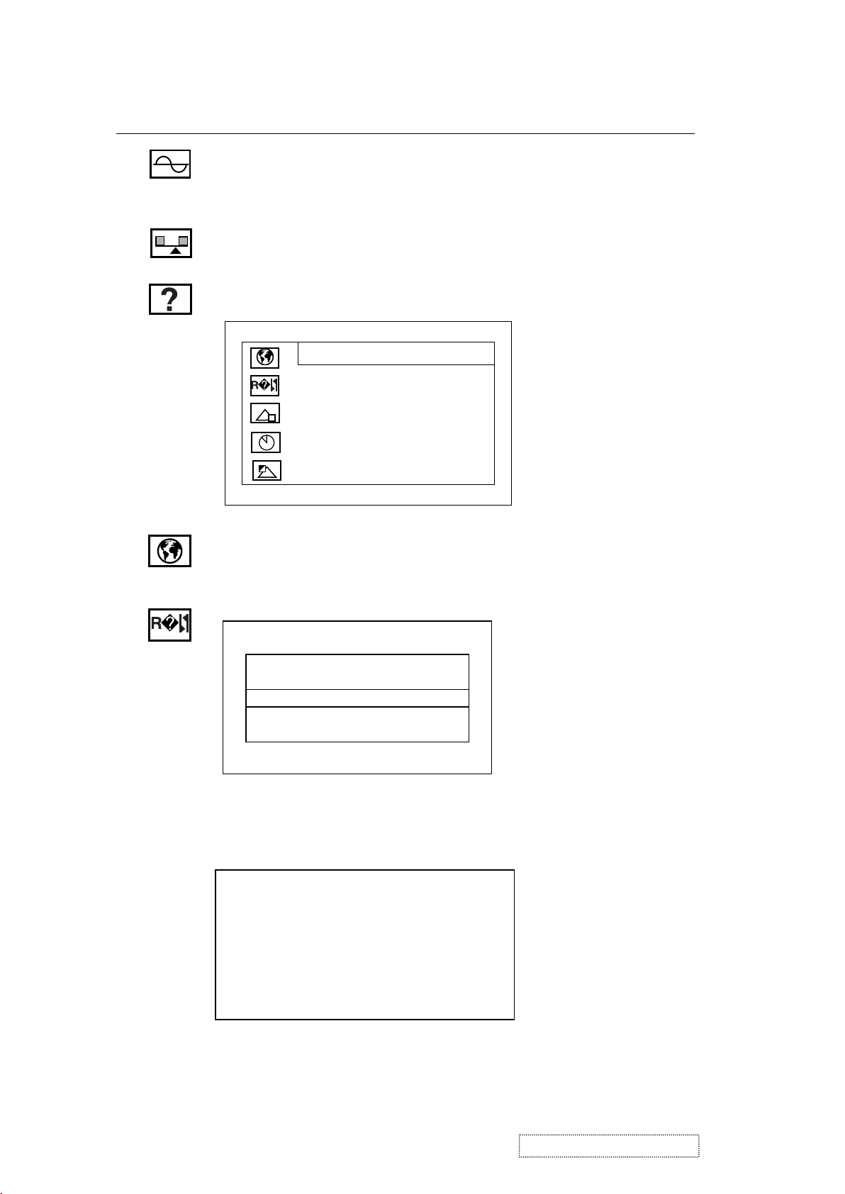
Fine Tune
sharpens the focus by aligning the text and/or graphic
characters.
NOTE:
Sharpness
Try Auto Image Adjust first.
adjusts the clarity and focus of the screen image.
Setup menu displays the menu shown below:
Setup Menu
Language Select
Resolution Notice
OSD Position
OSD Time Out
OSD Background On/Off
1: Exit 2: Select
Language
allows you to choose the language used in the menus
and control screens.
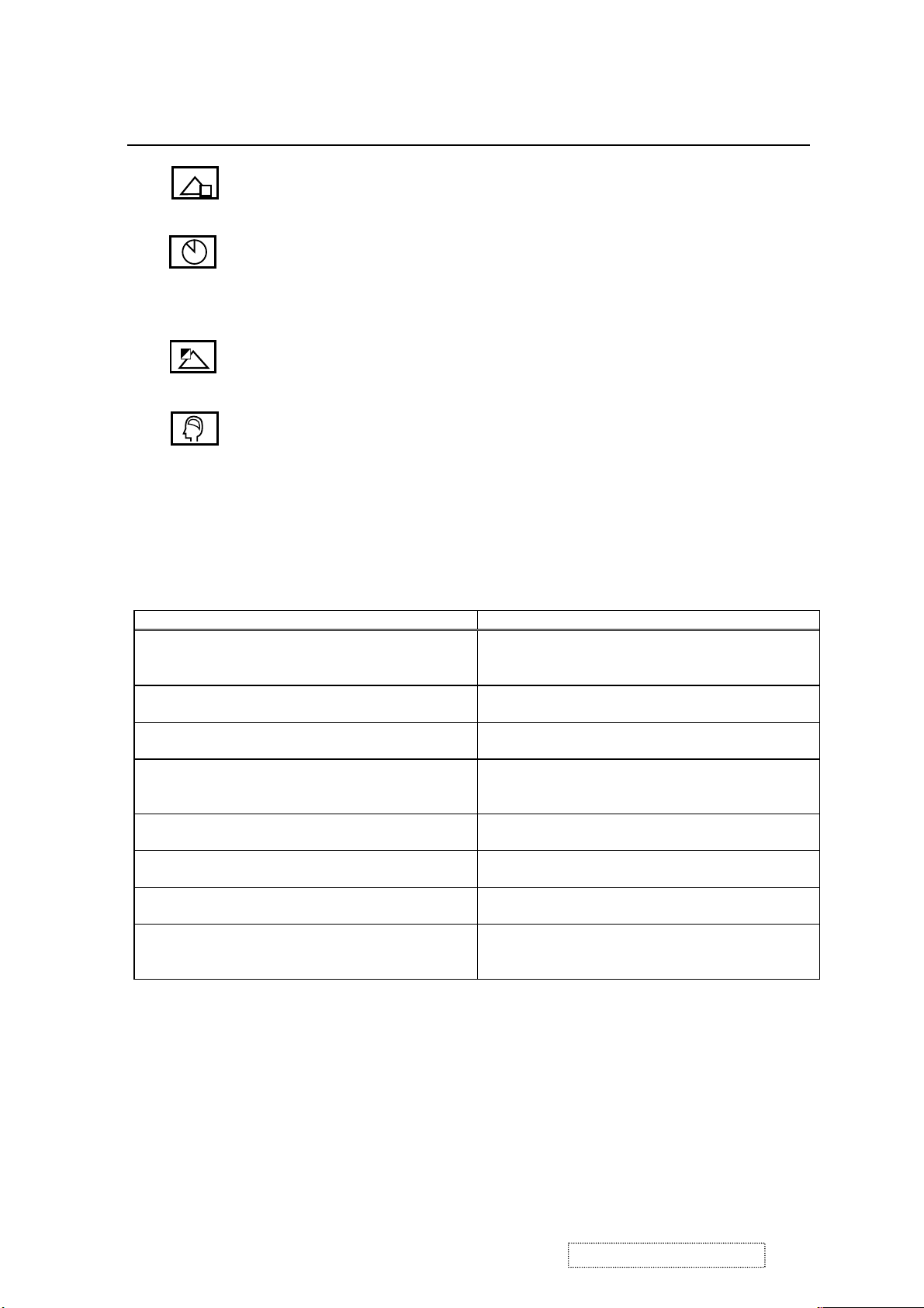
Resolution Notice
Resolution Notice
˙On ˙Off
1: Exit
allows you to enable or disable this notice.
If you enable the Resolution Notice shown above and your
computer is set at a resolution other than 1280 x 1024, the
following screen appears.
Resolution Notice
For best picture quality, change the resolution to 1280 x 1024
Press "1" to Clear Message.
Press "2" to Disable Message.
ViewSonic Corporation Confidential
12
-
Do Not Copy VG710b/s-1
Page 16
Control Explanation
OSD Position
and control screens.
OSD Timeout
screen is displayed. For example, with a “30 second” setting, if a
control is not pushed within 30 seconds, the display screen
disappears.
OSD Background
background On or Off.
Memory Recall
if the display is operating in a factory Preset Timing Mode listed
in the Specifications of this manual.
Hot Keys for Function Controls
Buttons: Functions:
[Up] + [Down] arrows recall Contrast or Brightness while in the Contrast
[Volume-] + [Volume+] recall volume to 50% while in volume adjustment,
[1] + [2] toggle 720x400 and 640x400 mode when input
[1] + [Up] + [Down] White Balance. White Balance should set the screen
[1] + [Down] (hold for 10 seconds) Power Lock (Unlock). User won’t be able to turn off
[1] + [Up] (hold for 10 seconds) OSD Lock (Unlock). It will lock all functions,
[Up] + [Down] + [Power On] with signal
(hold for 3 seconds)
[Up] + [Down] + [Power On]
without signal
(hold for 3 seconds)
allows you to move the on-screen display menus
sets the length of time the on-screen display
On/Off
allows you to turn the On-Screen Display
returns the adjustments back to factory settings
or Brightness adjustment, or recall both of Contrast
and Brightness when the OSD is not on.
or when OSD is not on.
720x400 or 640x400 mode.
on the pure black and white pattern with
640*480@60Hz resolution.
the monitor.
including “Volume” and “Mute”.
All Mode Reset. It will erase all end users’ settings
and restore the factory defaults.
Burn in Mode. After entering Burn in Mode, press
[1] button, you can find the information about this
monitor.
ViewSonic Corporation Confidential
13
-
Do Not Copy VG710b/s-1
Page 17
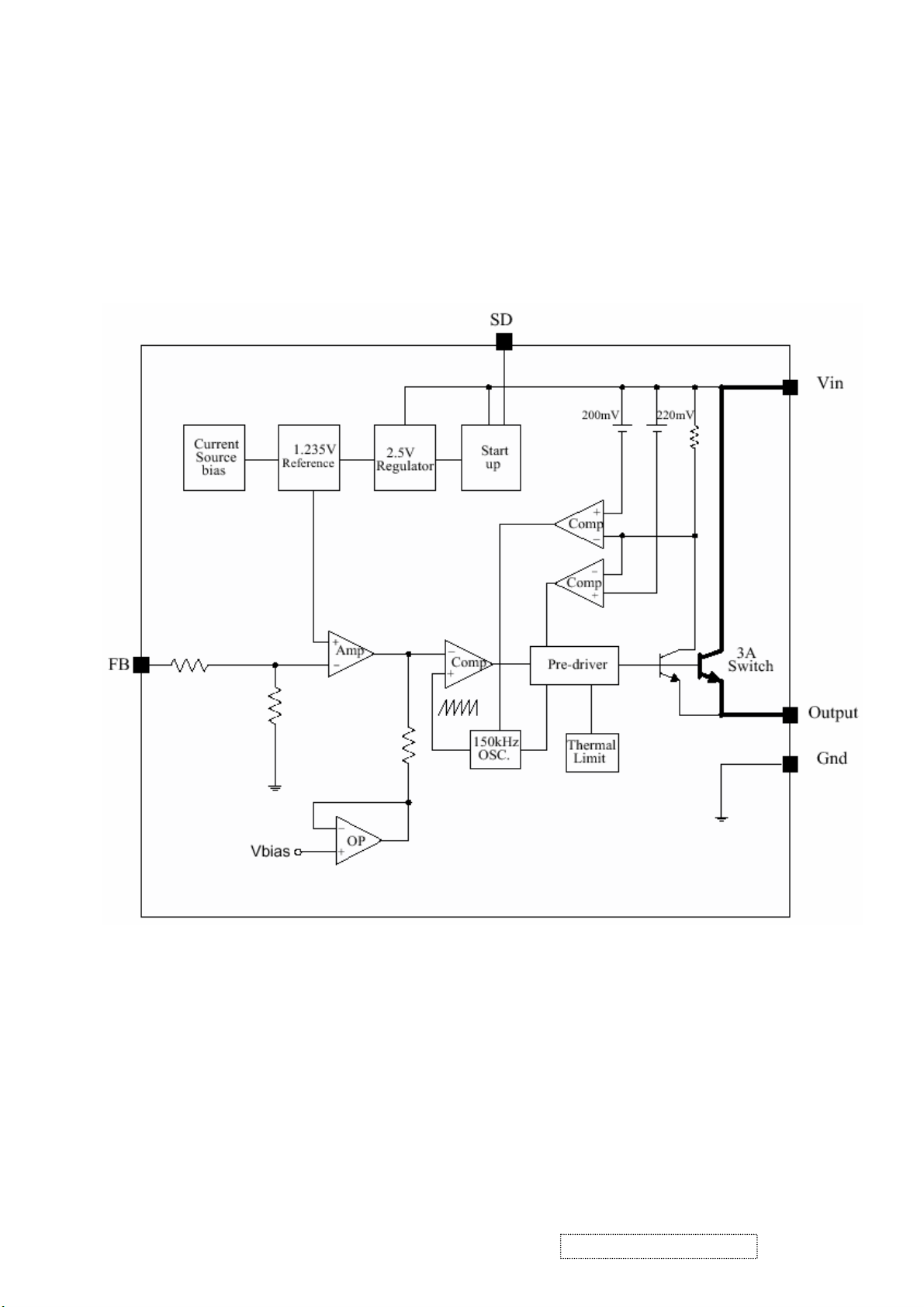
4. Circuit Description
1. Power s»(D C/DC Converter)
The AP1501 is monolithic IC designed for M/B DC/DC converter, with the ability of driving a 3A load without any
additional transistor component.
The AP1501 operates at a switching frequency of 150 kHz and thus allows smaller-sized filter components than
would be needed with lower frequency switch regulator.
2. Flash Memory
The Pm39LV010R is a 1 Megabit, 3.3 Volt-only Flash Memory organized as 131,072 bytes of 8 bits each. This device is
designed to use a 3.0 Volt to 3.6 Volt power supply to perform in-system programming.
The 1 Megabit memory array is divided into thirty-two uniform blocks of 4 Kbytes each for data and/or code storage.
The block architecture allows users to flexibly make chip erase or block erase operation. The block erase feature allows a
particular block to be erased and reprogrammed without affecting the data in other blocks. After the device performs chip
erase or block erase operation, it can be reprogrammed on a byte-by-byte basis.
ViewSonic Corporation Confidential
14
-
Do Not Copy VG710b/s-1
Page 18
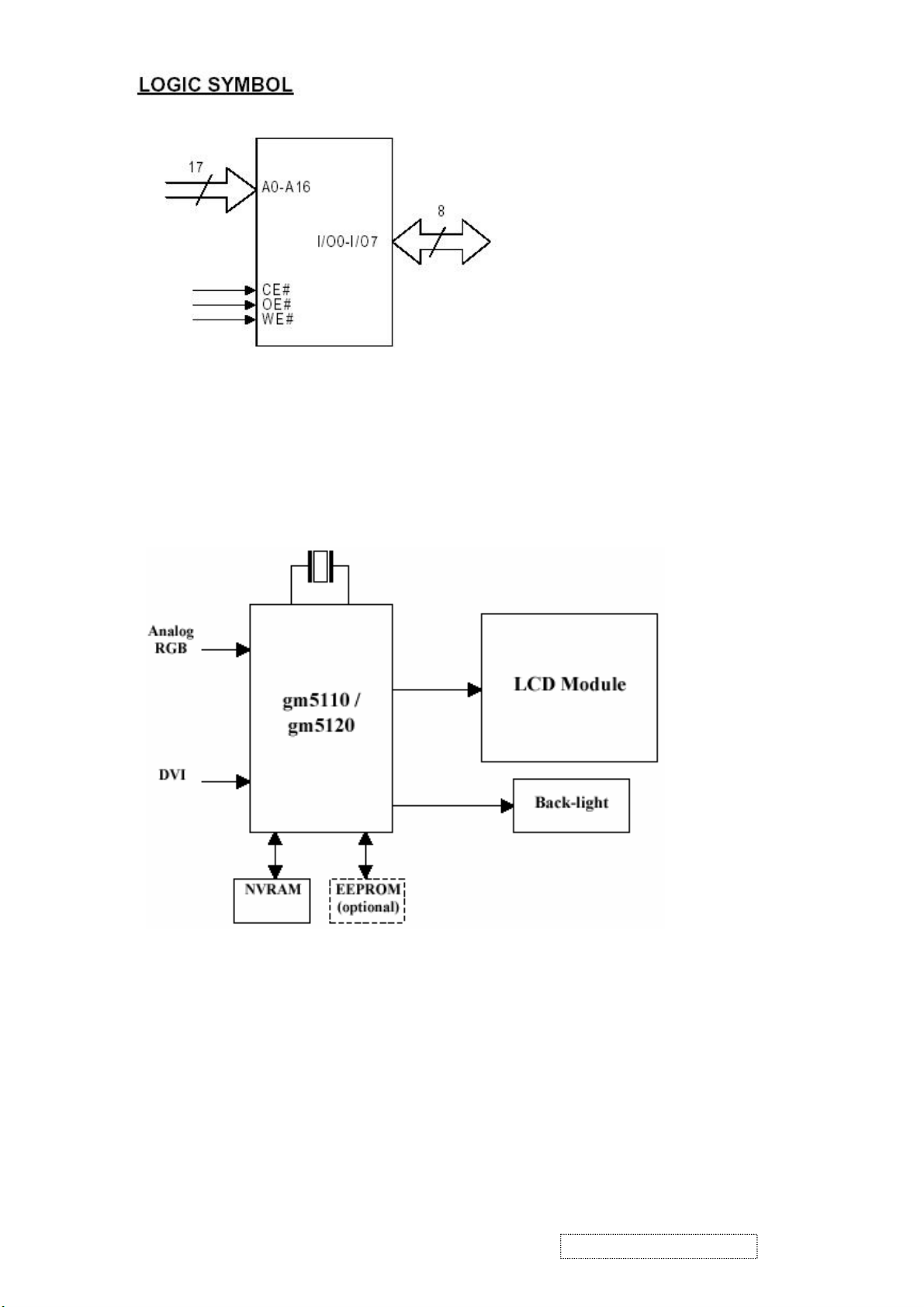
3. GM5120
The gm5110/20 is a graphic processing IC for Liquid Crystal Display (LCD) monitors at XGA/SXGA resolution. It
provides all key IC functions required for the highest quality LCD monitors. On-chip functions include a high-speed
triple-ADC and PLL, Ultra-Reliable DVI
TM
receiver, a high quality zoom and shrink scaling engine, an on-screen display
(OSD) controller, digital color controls and an on-chip microcontroller (OCM). With this level of integration, the
gm5110/20 devices simplify and reduce the cost of LCD monitors while maintaining a high-degree of flexibility and
quality.
gm5110/5120 System Design Example
4. LVDS (THC63LVDM83A)
The THC63LVDM83A transmitter converts 28 bits of CMOS/TTL data into LVDS (Low Voltage Differential Signaling)
data stream. A phase-locked transmit clock is transmitted in parallel with the data streams over a fifth LVDS link. The
HC63LVDM83A can be programmed for rising edge or falling edge clocks through a dedicated pin. The THC63LVDF84A
receiver converts the LVDS data streams back into 28 bits of CMOS/TTL data with falling edge clock. At a transmit clock
frequency of 85MHz, 24 bits of RGB data and 4 bits of LCD timing and control data (HSYNC, VSYNC, CNTL1, CNTL2)
are transmitted at a rate of 595 Mbps per LVDS data channel.
ViewSonic Corporation Confidential
15
-
Do Not Copy VG710b/s-1
Page 19
5. Adjusting Procedure
1. Function Test
1.1 Product
- 17” LCD Monitor
1.2 Test Equipment
- Color Video Signal & Pattern (or PC with SXGA resolution and a sound card)
1.3 Test Condition
Before function test and alignment, each LCD Monitor should be warmed up for at least 30 minutes with the
following conditions:
(a) In room temperature,
(b) With full-white screen, RGB, and Black
(c) With cycled display modes,
640*480 (H=43.27kHz, V=85Hz)
800*600 (H=53.7kHz, V=85Hz)
1024*768 (H=68.67kHz, V=85Hz)
1280*1024 (H=79.97kHz, V=75Hz)
1.4 Test Display Modes & Pattern
1.4.1 Compatible Modes
Analog Digital
1. 640 x 350 @ 70Hz, 31.5kHz
2. 640 x 480 @ 60Hz, 31.5kHz
3. 640 x 480 @ 67Hz, 35.0kHz
4. 640 x 480 @ 75Hz, 37.5kHz
5. 640 x 480 @ 72Hz, 37.9kHz
6. 640 x 480 @ 85Hz, 43.27kHz
7. 720 x 400 @ 70Hz, 31.5kHz
8. 800 x 600 @ 56Hz, 35.1kHz
9. 800 x 600 @ 60Hz, 37.9kHz
10. 800 x 600 @ 75Hz, 46.9kHz
11. 800 x 600 @ 72Hz, 48.1kHz
12. 800 x 600 @ 85Hz, 53.7kHz
13. 832 x 624 @ 75Hz, 49.7kHz
14. 1024 x 768 @ 60Hz, 48.4kHz
15. 1024 x 768 @ 70Hz, 56.5kHz
16. 1024 x 768 @ 72Hz, 58.1kHz
17. 1024 x 768 @ 75Hz, 60.0kHz
18. 1024 x 768 @ 85Hz, 68.67kHz
19. 1280 x 1024 @ 60Hz, 63.4kHz
20. 1280 x 1024 @ 75Hz, 79.97kHz
640 x 350 @ 70Hz, 31.5kHz
640 x 400 @ 60Hz, 31.5kHz
640 x 480 @ 60Hz, 31.5kHz
640 x 480 @ 75Hz, 37.5kHz
640 x 480 @ 72Hz, 37.9kHz
640 x 480 @ 85Hz, 43.27kHz
720 x 400 @ 70Hz, 31.5kHz
800 x 600 @ 56Hz, 35.1kHz
800 x 600 @ 60Hz, 37.9kHz
800 x 600 @ 75Hz, 46.9kHz
800 x 600 @ 72Hz, 48.1kHz
800 x 600 @ 85Hz, 53.7kHz
1024 x 768 @ 60Hz, 48.4kHz
1024 x 768 @ 70Hz, 56.5kHz
1024 x 768 @ 72Hz, 58.1kHz
1024 x 768 @ 75Hz, 60.0kHz
1024 x 768 @ 85Hz, 68.67kHz
1280 x 1024 @ 60Hz, 63.4kHz
ViewSonic Corporation Confidential
16
-
Do Not Copy VG710b/s-1
Page 20
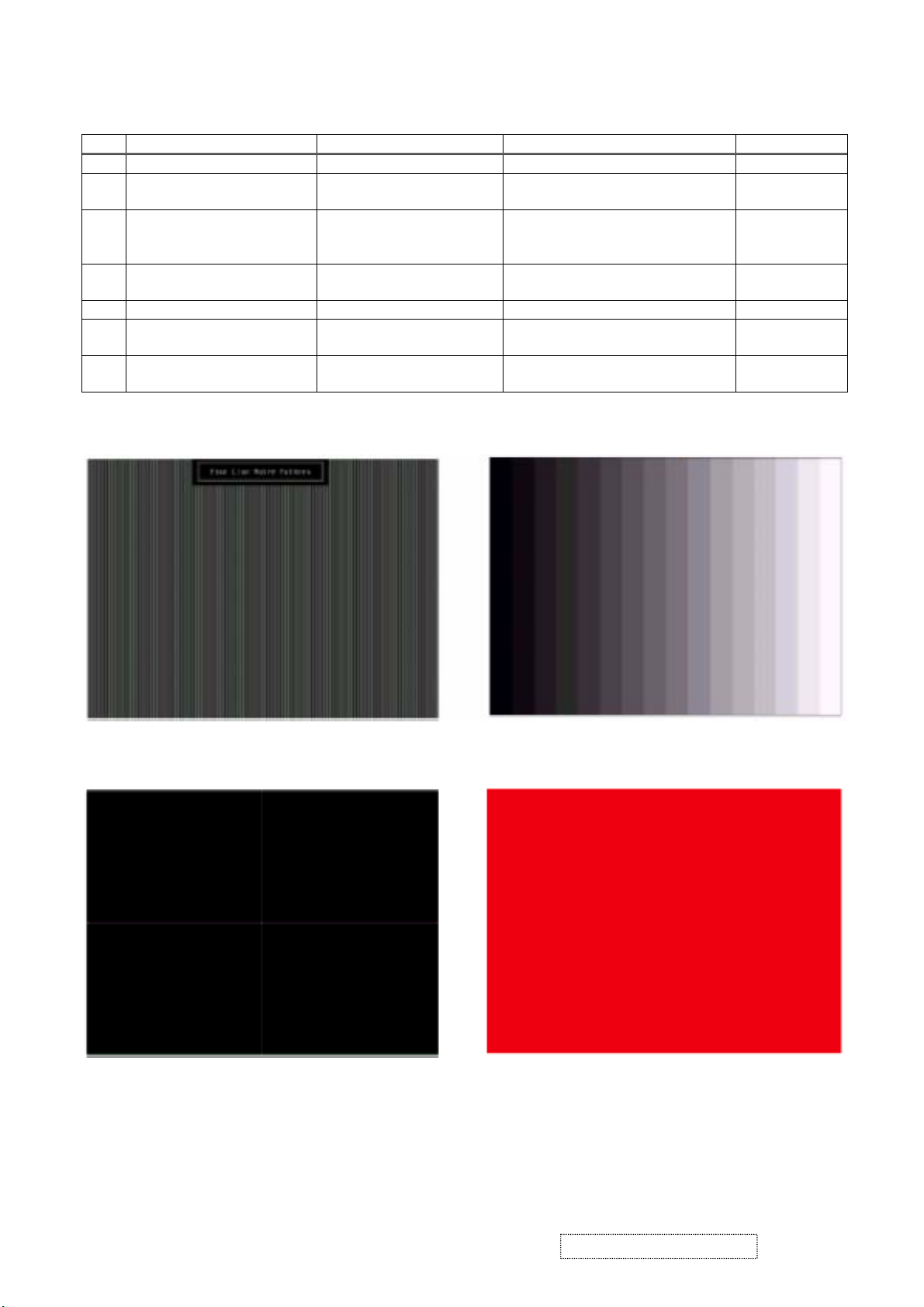
1.4.2 Function Test Display Pattern
Item Test Content Pattern Specification Remark
1 Frequency & Tracking Fine Line Moire Eliminate visual wavy noise. Figure 1
2 Contrast/Brightness 16 Gray Scale 16 gray levels should be
Figure 2
distinguishable.
3 Boundary Horizontal & Vertical
Thickness
Horizontal and Vertical position of
video should be adjustable to be
Figure 3
within the screen frame.
4 RGB Color Performance RGB Color Intensities Contrast of each R, G, B, color
Figure 4, 5, 6
should be normal.
5 Screen Uniformity & Flicker Full White Should be compliant with the spec. Figure 7
6 Dead Pixel/Line White Screen & Dark Screen The numbers of dead pixels should
Figure 7, 8
be compliant with the spec.
7 White Balance White & Black Pattern The screen must have the pure white
Figure 9
and black pattern, no other color.
Fine Line Morie Pattern (Figure1) Gray Scale Pattern (Figure2)
Horizontal & Vertical Thickness Pattern (Figure 3) R. Color Pattern (Figure 4)
ViewSonic Corporation Confidential
17
-
Do Not Copy VG710b/s-1
Page 21
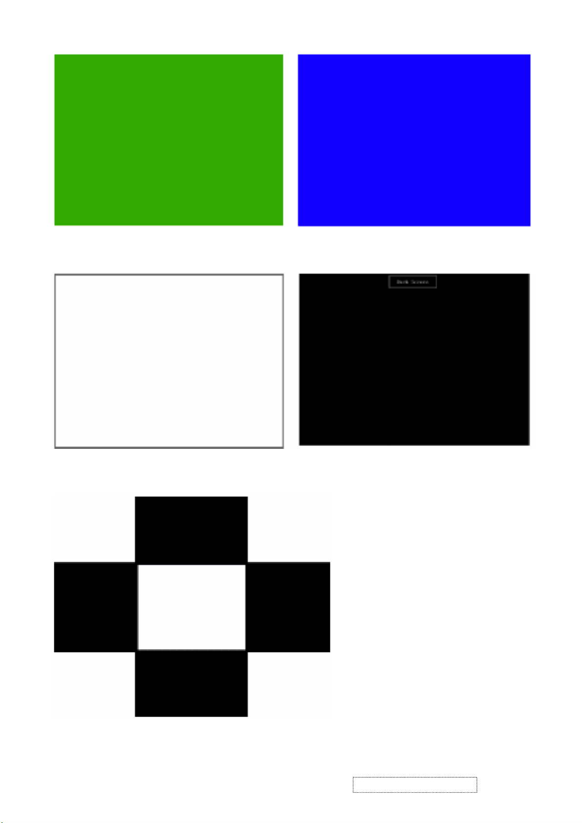
G. Color Pattern (Figure5) B. Color Pattern (Figure 6)
Full White Pattern (Figure 7) Dark Screen Pattern (Figure 8)
Black-White Pattern (Figure 9)
ViewSonic Corporation Confidential
18
-
Do Not Copy VG710b/s-1
Page 22

1.5 Function Test and Alignment Procedure
1.5.1 All Modes Reset
You should do “All Mode Reset” (Refer to Chapter III-3. Hot Keys for Function Controls) first. This action will allow you
to erase all end-user’s settings and restore the factory defaults.
1.5.2 Auto Image Adjust
Please select and enter “Auto Image Adjust” function on Main Menu to see if it is workable. The “Auto Image Ad just”
function is aimed to offer a better screen quality by built-in ASIC. For optimum screen quality, the user has to adjust each
function manually.
1.5.3 Firmware
Test Pattern: Burn In Mode (Refer to Chapter III-3. Hot Keys for Function Controls)
- Make sure the F/W is the latest version.
1.5.4 DDC
Test Pattern: EDID program
- Make sure it can pass test program.
1.5.5 Fine Tune and Sharpness
Test Signal: 1280*1024@60Hz
Test Pattern: Line Moire Pattern
- Check and see if the image has noise and focus performs well. Eliminate visual line bar.
- If not, readjust by the following steps:
(a) Select and enter “Fine Tune” function on “Manual Image Adjust” to adjust the image to eliminate visual wavy noise.
(b) Then, select and enter “Sharpness” function to adjust the clarity and focus of the screen image.
1.5.6 Boundary
Test Signal: 1280*1024@60Hz
Test Pattern: Horizontal & Vertical Line Thickness Pattern
- Check and see if the image boundary is within the screen frame.
- If not, readjust by the following steps:
(a) Select and enter “Manual Image Adjust” function on OSD Main Menu.
(b) Then, select and enter “Horizontal Size” or “Horizontal/Vertical Position” function to adjust the video boundary to
be full scanned and within screen frame.
1.5.7 White Balance
Test Signal: 640*480@60Hz
Test Pattern: White and Black Pattern
ViewSonic Corporation Confidential
19
-
Do Not Copy VG710b/s-1
Page 23

1.5.8 R, G, B, Colors Contrast
Test Signal: 1280*1024@60Hz
Test Pattern: R, G, B, Color Intensities Pattern and 16 Gray Scale Pattern
- Check and see if each color is normal and distinguishable.
- If not, please return the unit to repair area.
1.5.9 Screen Uniformity and Flicker
Test Signal: 1280*1024@60Hz
Test Pattern: Full White Pattern
- Check and see if it is in normal condition.
1.5.10 Dead Pixel and Line
Test Signal: 1280*1024@60Hz
Test Pattern: Dark and White Screen Pattern
- Check and see if there are dead pixels on LCD panel with shadow gauge and filter film.
- The total numbers and distance of dead pixels should be compliant with the spec.
1.5.11 Mura
Test Pattern: White, RGB, Black, & Grey
Test Tool: 10% ND Filter
- Check if the Mura can pass 10% ND Filter.
1.5.12 Audio
Test Signal: Voice signal (optional, depend on model)
Test Pattern: liberty
- Make sure there is audio output.
- Make sure that audio function (volume 80%) is working without noise and resonance.≦
- Make sure that the sound of right and left speakers are in balance.
1.5.13 Check for Secondary Display Modes
Test Signal:
Analog: 640*350@70Hz; 640*480@60/67/72/75/85Hz;
720*400@70Hz; 800*600@56/60/72/75/85Hz;
832*624@75Hz, 1024*768@60/70/72/75/85Hz;
1280*1024@60/75Hz
Digital: 640*350@70Hz; 640*480@60/72/75/85Hz;
720*400@70Hz; 800*600@56/60/72/75/85Hz;
1024*768@60/70/72/75/85Hz; 1152*870@75Hz,
1280*720@60Hz, 1280*1024@60Hz
- Normally when the primary mode 1280*1024@60Hz is well adjusted and compliant with the specification, the
secondary display modes will also be compliant with the spec. But we still have to check with the general test pattern
to make sure every secondary is compliant with the specification.
ViewSonic Corporation Confidential
20
-
Do Not Copy VG710b/s-1
Page 24
1.5.14 All Modes Reset
After final QC step, we have to erase all saved changes again and restore the factory defaults. You should do “All Mode
Reset” again.
1.5.15 Power Off Monitor
Turn off the monitor by pressing “Power” button.
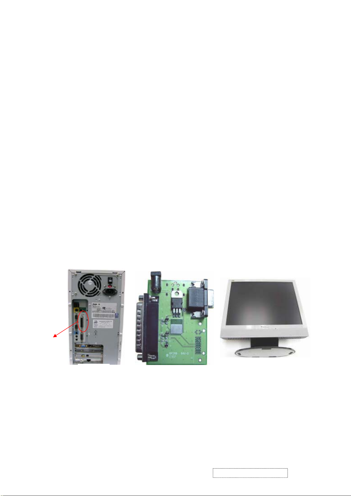
2. Firmware Upgrade Procedure
When you receive the returned monitor, please check whether the firmware version is the latest. If not, please do
the following procedures to upgrade it to the latest version.
2.1 Equipment Needed
- VG710 Monitor
- Fixture for Firmware Upgrade
- Power Adapter (P/N: 47.58201.001) *1 for Fixture
- VGA Cable (P/N: 42.59901.003) *1(Pin 4, 11 should be connected to GND)
- PC (Personal Computer)
- LPT Cable (P/N: 42.59906.001) *1
- Firmware Upgrade Program
- One additional monitor for checking the program execution
Printer Port
PC VG710
Fixture
ViewSonic Corporation Confidential
21
-
Do Not Copy VG710b/s-1
Page 25

Power Adapter for Fixture
2.2 Setup Procedure
2.2.1 Connect P2 of Fixture with printer port of PC by LPT Cable.
2.2.2 Connect P1 of Fixture with VG710 Monitor by VGA Cable.
2.2.3 Plug Power Adapter to Fixture.
2.2.4 Connect Power Cord to VG710 Monitor.
2.2.5 Connect PC to the additional monitor.
(P/N: 47.58201.001)
JP1: to Power Adapter
P2: to LPT Cable
LPT Cable
(P/N: 42.59906.001)
VGA Cable
(P/N: 42.59901.003)
P1: to VGA Cable
ViewSonic Corporation Confidential
22
-
Do Not Copy VG710b/s-1
Page 26

2.2.6 Install GProbe Program by selecting and clicking Gprobe icon. Press “Yes” or “Next” buttons until the installation is complete.
ViewSonic Corporation Confidential
23
-
Do Not Copy VG710b/s-1
Page 27

ViewSonic Corporation Confidential
24
-
Do Not Copy VG710b/s-1
Page 28

ViewSonic Corporation Confidential
25
-
Do Not Copy VG710b/s-1
Page 29

2.3 Firmware Upgrade Procedure
ViewSonic Corporation Confidential
26
-
Do Not Copy VG710b/s-1
Page 30

Step 1. Let VG710 enter Burn In Mode. (Refer to Chapter III-3. Hot Keys for Function Controls).
Step 2. Save these three files<bdisp.txt>, <p204_205.bin> and <710LG_V2_48.bin> in a hard disk (better in a root directory, e.g.
C:\ or D:\ ).
Step 3. Open <bdisp.txt> file. Key in the path where you save the driver <p204_205.bin> and firmware <710LG_V2_48.bin>.
ViewSonic Corporation Confidential
27
-
Do Not Copy VG710b/s-1
Page 31

Step 4. Execute Gprobe program.
Step 5. Click Connection Setup icon. Select Protocol: DDC 2Bi3, Port: LPT1 (0x378), Speed: 70000.
ViewSonic Corporation Confidential
28
-
Do Not Copy VG710b/s-1
Page 32

Step 6. Before executing the firmware program, please test the connection between the monitor and fixtures. Key in “test” after
“Gprobe,” and then press “Enter.”
If the test result shows “passed,” it means the connection is well. If not (failed), it means the connection has
problems. Then you need to check the setup procedure or reboot the PC, or simply use another PC to do the
firmware upgrade.
ViewSonic Corporation Confidential
29
-
Do Not Copy VG710b/s-1
Page 33

Step 7. Key in “batch C:\VG710\bdisp.txt” after “Gprobe:”, and then press “Enter” key to begin programming automatically.
Step 8. The successful picture is as follows:
ViewSonic Corporation Confidential
30
-
Do Not Copy VG710b/s-1
Page 34

Step 9. Unplug and replug power cord of VG710 and then enter “Burn In Mode” (Refer to Chapter III-3. Hot Keys for Function
Controls). Check if the version of BIOS is correct.
Step 10. At last, do “All Mode Reset.”
Troubleshooting:
1. If the firmware upgrade fails at the last step, don’t unplug the power cord of the monitor. Just try the upgrade
procedure again.
(a) If there is error to execute the command at or before line10 in the “bdisp.txt” batch file (for instance, the
message “Error executing batch file at line 4” shows up in the Gprobe program (see the following picture)),
please try to upgrade the firmware again.
ViewSonic Corporation Confidential
31
-
Do Not Copy VG710b/s-1
Page 35

Test failed.
Test failed.
Test failed.
Test failed.
Test failed.
Test failed.
Error executing batch file at line 4.
Execution time: 5.72s
GProbe:>
(b) If there is error to execute the command at or after line11 in the “bdisp.txt” batch file, please copy the error line
of the “bdisp.txt” batch file to “Gprobe:>” in the Gprobe program, and then press “Enter.” For example, there
is “Error executing batch file at line 16” (see the following picture). Then you have to copy line 16
“FLASHWRITE C:\VG710\710LG_V2_48.bin” to “Gprobe:>” in the Gprobe program, and then press “Enter”
(see the picture next page).
Test passed.
Test passed.
Test passed.
Erasing FLASH... Done.
Writing FLASH...
Writing FLASH... FAILED.
Error executing batch file at line 16.
Execution time: 9.61s
GProbe:>
ViewSonic Corporation Confidential
32
-
Do Not Copy VG710b/s-1
Page 36

Line 16
Copy the error line of the
“bdisp.txt” batch file to
“Gprobe:>”
2. If the firmware upgrade still fails, reboot the PC, or simply use another PC to upgrade.
3. If the above procedures don’t work, unplug and re-plug the power cord of the monitor. Then try to upgrade the
ViewSonic Corporation Confidential
33
-
Do Not Copy VG710b/s-1
Page 37

firmware again if the monitor can be powered on. If the monitor cannot be turned on, that means the flash
memory of the main board is out of work. You then have to replace the main board.
3. DDC Key In Procedure
Note:
1. Every time after replacing the main board, you have to do the DDC key in.
2. If you find the DDC does not conform to the monitor, you have to do the DDC key in.
3.1 Equipment Needed
- VG710 Series Monitor
- Fixture (V3) for DDC Key in (JP3 must be closed)
- RS232 Cable (P/N: 42.55907.001) *1
- VGA Cable (P/N: 42.59901.003) *2
- DVI-DVI Cable *1 (P/N: 42.56108.012)
- PC (Personal Computer) with Win 98
- Power Adapter (P/N: 47.56001.501) *1 for Fixture
- DDC Key In Program
- One additional monitor for checking the program execution
COM1:
to
RS232
Cable
PC
JP3 must be closed
V3 Fixture VG710
ViewSonic Corporation Confidential
RS-232 Cable
(P/N: 42.55907.001)
DVI-DVI Cable
(P/N: 42.56108.012)
32
34
Power Adapter for Fixture
(P/N: 47.56001.501)
-
Do Not Copy VG710b/s-1
Page 38

3.2 Setup Procedure
3.2.1 Connect P2 and P4 of Fixture with VGA ports of VG710 by VGA Cable.
3.2.2 Connect P3 of Fixture with DVI port of VG710 by DVI-DVI Cable.
3.2.3 Connect P1 of Fixture with COM1 of PC by RS-232 Cable.
3.2.4 Plug Power Adapter to Fixture.
VGA Cable (P/N: 42.59901.003)Barcode Reader
3.2.5 Connect Power Cord to VG710 Monitor.
3.2.6 Connect PC to the additional monitor.
P3: to DVI-DVI Cable
JP1: to Power
Adapter
3.3 DDC Key In Procedure
P2: to VGA Cable
JP3 must be closed
P1: to RS232 Cable
ViewSonic Corporation Confidential
35
-
Do Not Copy VG710b/s-1
Page 39

Step 1. Select and execute DDC Key In program.
Step 2. Select “W/w - writing mode.”
ViewSonic Corporation Confidential
36
-
Do Not Copy VG710b/s-1
Page 40

Step 3. Key in the serial number or use the barcode reader to scan the barcode of the monitor, and then press “Enter” key.
Step 4. The successful picture is as follows. “The checksum values will appear after DDC is upgraded successfully in both VGA
and DFP (DVI) modes.”
ViewSonic Corporation Confidential
37
-
Do Not Copy VG710b/s-1
Page 41

Step 5. Let VG710 enter “Burn In Mode” (Refer to Chapter III-3. Hot Keys for Function Controls). Unplug and re-plug the
power cord of the monitor. The corrective serial number will show on the screen.
Step 6. Checking Method:
- Execute the DDC Key In program and select “R/r - Reading mode” in Step 2.
- Use barcode reader to scan the barcode of the monitor. If the DDC is correct, the “Send VGA” and “Send DFP” will
show “Check Pass!” message.
ViewSonic Corporation Confidential
38
-
Do Not Copy VG710b/s-1
Page 42

6. Trouble Shooting Flow Chart
This chapter provides technicians and people who have an electronic background a primary description about maintaining
the product. Moreover, you can get the appropriate operation to solve some complicated problems of component repairing
and professional problems.
1. Equipment Needed
- VG710 Monitor
- Philips Screw Driver #101 and #107
- Electronic Hex Nut M5 mm
- PC (Personal Computer) with SXGA resolution and sound card / Pattern Generator
2. Main Procedure
ViewSonic Corporation Confidential
39
-
Do Not Copy VG710b/s-1
Page 43

2.1 A. Power Circuit Troubleshooting
2.2 B. Performance Troubleshooting
ViewSonic Corporation Confidential
40
-
Do Not Copy VG710b/s-1
Page 44

Notice:
1. Make sure VGA cable connected to PC directly, not via anything like “Data transfer” or “Distribution” ……After this
ViewSonic Corporation Confidential
41
-
Do Not Copy VG710b/s-1
Page 45

action if Ghost image disappears, go to “Yes”; else, go to “No.”
2. Check the compatibility on the computer. If it is compatibility problem, feedback the information to ViewSonic; else, go
to “No.”
2.3 C. Function Troubleshooting
2.4 D. Speakers Troubleshooting
ViewSonic Corporation Confidential
42
-
Do Not Copy VG710b/s-1
Page 46

7. Recommended Spare Parts List
VG710s-1 RSPL
Rev 1b
Item Revision History ViewSonic P/N Ref. P/N Description Location Universal # Q'ty
1 M-LB-0813-0781 35.61203.001 LABEL BAR CODE 50*25mm VP191 BARCODE LABEL 1
2a Removed 08/04/04 M-LB-0813-0888 35.62701.001 LABEL SPEC 120*50mm VG710s SPEC LABEL 1
2b Added 08/04/04
3 M-MS-0808-8946 35.62702.001 BIRD LOGO AL E015-006 VG710s LOGO 1
4 M-MS-0808-8947 35.62703.001 COSMETIC STRIP ADHESIVE CS-VS06 140*21*0.3t COMETIC STRIP 1
5 M-MS-0808-8948 35.62704.001 ViewSonic AL-LOGO E015-016-1 ViewSonic LOGO 1
6a Removed 08/04/04 A-CD-VG710S 36.62701.001 USER GUIDE+CD VG710s USER GUIDE 1
6b Added 08/04/04
7 M-MS-0808-8882 41.55601.001 EMI Tape (80773) 20*40mm EMI TAPE 3
8 M-MS-0808-8949 41.58301.001 EMI TAPE 80773 25*75mm EMI TAPE 1
9 M-MS-0808-8950 41.61603.001 EMI GASKET 773GT W6*H6.5*L30 EMI TAPE 1
10 M-WR-0828-0636 42.58301.001 W.A. 10/6P UL1007 #24 100mm VG700(INV) WIRE 1
11 M-WR-0828-6009 42.58302.005 W.A. 30P UL20276 #28 200mm W/O CORE WIRE 1
12 M-WR-0828-6010 42.58303.001 W.A. 12P UL1571 #28 260mm W/O CORE SHARE(MB/CTRL) WIRE 1
13 A-VC-0101-0261 42.59901.003 CABLE VGA 15P 1800mm 2*25mm CORE VGA CABLE 1
14 A-AU-0120-0032 42.59903.001 CABLE AUDIO 1.8M LM/BK/LM VX2000 AUDIO CABLE 1
15 B-SB-0221-0565 44.58402.001 INVERTER PLCD2417414F;EMAX FOR 17" SAMSUNG INVERTER 1
16 A-AD-0114-0204 47.62701.001 ADAPTER IN100-240V 12V/3.33A;"LSE" ADAPTER 1
17a Removed 08/04/04 M-LCD-0826-0178 48.61101.001 TFT LCD 17" LG LM170E01-A5,SXGA LCD PANEL 1
17b Added 08/04/04
18 E-SK-0412-0080 49.62701.001 SPEAKER 3W FOR VG710 SPEAKER 1
19 M-MS-0808-8797 51.00014.002 FILAMENT TAPE 3M NO.8915 25mm*55M FILAMENT TAPE 0.0011
20a Removed 08/04/04 M-MS-0808-8951 51.58204.001 PE BAG LDPE 420*600*0.07t W/HOLE FOR VG500 PE BAG 1
20b Added 08/04/04
21 M-MS-0808-8952 51.58314.001 LCD PROTECT FILM 355*290*0.1t mm MYLAR VG700/VG750 PROTECT FILM 1
22a Removed 08/04/04 M-MS-0808-8116 51.58711.001 NAMEPLATE ELLIPSE ViewSonic NAMEPLATE 1
22b Added 08/04/04
23 M-MS-0808-8953 51.59907.001 WIRE MOUNT MC-03A "G&A" VX930 WIRE MOUNT 5
24 M-MS-0808-8750 51.61103.001 MYLAR ADHESIVEt=0.3mm VP171 MYLAR 1
25a Removed 08/04/04 M-MS-0808-8969 51.62703.001 HINGE CAP ABS HB-VS06 VG710s HINGE CAP 1
25b Added 08/04/04
26a Removed 08/04/04 M-CV-0830-2780 51.62706.001 BASE COVER ABS HB-VS06 VG710s BASE COVER 1
26b Added 08/04/04
27a Removed 08/04/04 M-MS-0808-8970 51.62707.001 FRONT ARM ABS HB-VS06 VG710s FRONT ARM 1
27b Added 08/04/04
28a Removed 08/04/04 M-MS-0808-8971 51.62708.001 REAR ARM ABS HB-VS06 VG710s REAR ARM 1
28b Added 08/04/04
29a Removed 08/04/04 M-MS-0808-8957 51.62709.001 MYLAR ADHESIVE 350*28*0.05t(BLACK) VG710s MYLAR 1
29b Added 08/04/04
30a Removed 08/04/04 M-MS-0808-8958 52.57503.001 RUBBER FOOT 35*10*1.2t TFT8030 RUBBER FOOT 5
30b Added 08/04/04
31a Removed 08/04/04 M-MS-0808-8972 52.62701.001 VESA RUBBER PAD D7.0*H4.5 VG710s RUBBER PAD 4
31b Added 08/04/04
32a Removed 08/04/04 P-BX-0601-0895 55.62701.001 CARTON AB-18 455*205*480(h) VG710s CARTON 1
32b Added 08/04/04
33 P-FM-0602-0818 56.62701.001 CUSHION R EPS VG710s RIGHT CUSHION 1
34 P-FM-0602-0819 56.62702.001 CUSHION L EPS VG710s LEFT CUSHION 1
35 M-BK-0805-0020 61.61102.002 SHIELDING BRKT-INV TINEPLATE 0.3t VG710s SHIELDING BRKT 1
36 M-BK-0805-0021 61.62701.001 LCD BRKT SECC 1.0t VG710s LCD BRKT 1
37 M-BK-0805-0022 61.62702.001 SHIELDING BRKT-MB SECC 1.0t VG710s SHIELDING BRKT 1
38 M-MS-0808-8960 61.62703.001 BASE PLATE SPCC-Zn 2.5t VG710s BASE PLATE 1
39 M-MS-0808-8961 61.62704.001 HINGE SPCC-Zn 2.0t VG710s HINGE SPCC 1
40a Removed 08/04/04 C-FP-0301-0936 75.62701.001 ASSY FRONT COVER CS-VS07A VG710s FRONT COVER 1
40b Added 08/04/04
41a Removed 08/04/04 C-BC-0302-0540 75.62702.001 ASSY REAR COVER CS-VS06 VG710s REAR COVER 1
41b Added 08/04/04
42a Removed 08/04/04 B-MB-0201-0791 80.62701.001 PCBA MAIN BD VG710 "GM5120" MAIN BOARD 1
42b Added 08/04/04
43 B-CB-0206-0165 80.62702.001 PCBA CTRL BD VG710 CONTROL BOARD 1
44 Added 08/04/04
45 Added 08/04/04
46 Added 08/04/04
47 Added 08/04/04
48 Added 08/04/04
49 Added 08/04/04
50 Added 08/04/04
M-Model
Item Revision History ViewSonic P/N Ref. P/N Description Location Q'ty
1 Removed 08/04/04 A-PC-0106-0271 42.50112.001 CABLE POWER CORD 1830mm SP-023+IS14 EUR. POWER CORD 1
2 A-PC-0106-0270 42.57207.001 CABLE POWER CORD 1.8M±0.1M UNSHIELD (NA) POWER CORD 1
P-Model
Item Revision History ViewSonic P/N Ref. P/N Description Location Q'ty
1 Removed 08/04/04 A-PC-0106-0273 42.58204.001 CABEL POWER CORD 1830mm PC TYPE COLOR:BLACK POWER CORD 1
2 A-PC-0106-0270 42.57207.001 CABLE POWER CORD 1.8M±0.1M UNSHIELD (NA) POWER CORD 1
G-Model
Item Revision History ViewSonic P/N Ref. P/N Description Location Q'ty
1 A-PC-0106-0187 42.50126.001 CABLE POWER CORD 1.8M±0.1M (CHINA) POWER CORD 1
2 Added 08/04/04 M-MS-0808-8773 36.58307.002 WARRANTY CARD S. CHINESE SECOND VERSION VIEWSONIC WARRANTY 1
3 Added 08/04/04 M-LB-0813-0737 36.58308.001 WARRANTY STICKER S. CHINESE WARRANTY 1
4 Added 08/04/04 M-LB-0813-0739 36.58309.001 SHIPPING WARRANTY STICKER S. CHINESE VIEWSONIC WARRANTY 1
5 Added 08/04/04 M-MS-0808-9647 51.58317.001 PE BAG LDPE 750*760*0.05t VG700-1 PE BAG 1
E-Model
Item Revision History ViewSonic P/N Ref. P/N Description Location Q'ty
1 Added 08/04/04 A-PC-0106-0271 42.50112.001 CABLE POWER CORD 1830mm SP-023+IS14 EUR. POWER CORD 1.4
A-Model
Item Revision History ViewSonic P/N Ref. P/N Description Location Q'ty
1 Added 08/04/04 A-PC-0106-0270 42.57207.001 CABLE POWER CORD 1.8M±0.1M UNSHIELD (NA) POWER CORD 1.30
M-LB-0813-0882
A-CD-VG710B
M-LCD-0826-0250
M-MS-0808-9642
M-MS-0808-8299
M-MS-0808-8954
M-CV-0830-2479
M-MS-0808-8955
M-MS-0808-8956
M-MS-0808-9643
M-MS-0808-9645
M-MS-0808-8959
P-BX-0601-0891
C-FP-0301-0932
C-BC-0302-0539
B-MB-0201-2777
M-LB-0813-1016
M-LB-0813-0706
M-LB-0813-0736
M-LB-0813-1017
M-MS-0808-9644
M-MS-0808-9880
C-BS-0303-0571
35.62701.002 LABEL SPEC 120*50mm VG710b SPEC LABEL 1
36.62701.004 USER GUIDE+CD VG710b COST DOWN,FOR TCO'99 USER GUIDE 1
48.59302.001 TFT LCD 17.0" 1280*1024 AUO M17EN05 V8 PANEL CMO M170E5-L05 1
51.62710.001 PE BAG LDPE 450*700*0.07t W/HOLE VG710 PE BAG 1
51.58711.002 NAMEPLATE ELLIPSE CS-VS08 ViewSonic NAMEPLATE 1
51.62703.002 HINGE CAP ABS HB-VS08 VG710b HINGE CAP 1
51.62706.002 BASE COVER ABS HB-VS08 VG710b BASE COVER 1
51.62707.002 FRONT ARM ABS HB-VS08 VG710b FRONT ARM 1
51.62708.002 REAR ARM ABS HB-VS08 VG710b REAR ARM 1
51.62711.002 PC 30*12*0.6t mm VG710 2
52.62703.001 RUBBER FOOT 35*10*1.2t VG710 RUBBER FOOT 5
52.62701.002 VESA RUBBER PAD D7.0*H4.5 VG710b 4
55.62701.002 CARTON AB-18 455*205*480(h) VG710b CARTON 1
75.62701.002 ASSY FRONT COVER CS-VS08 VG710b 1
75.62702.002 ASSY REAR COVER CS-VS08 VG710b 1
80.62701.004 PCBA MAIN BD VG710 "GM5120+CMO-L05" MAIN BOARD GM5120 1
35.00010.002 LABEL CAUTION HIGH VOLTAGE 25.4*19mm CAUTION LABEL 1
35.58203.001 LABEL CARTON 76*76mm UPC LABEL 1
35.58304.001 LABEL BARCODE 40*14 ViewSonic BARCODE LABEL 1
35.59906.001 LABEL 210*65mm BLANK FOR PALLET 0.0625
52.62702.001 RUBBER SPACER 20*10*5.5mm 2
52.62703.003 RUBBER 30*15*3.5t BLACK VG710 1
70.62702.002 ASSY STAND CS-VS08 VG710b 1
ViewSonic Corporation Confidential
43
-
Do Not Copy VG710b/s-1
Page 47

ViewSonic P/N
Reference P/N
ViewSonic P/N
Reference P/N
VG710s-1 RSPL
Rev 1b
Revision History
Item
Description of Change
From To or Newly add Items
2 M-LB-0813-0888 35.62701.001 M-LB-0813-0882 35.62701.002 08/10/04: Removed and replaced part.
6 A-CD-VG710S 36.62701.001 A-CD-VG710B 36.62701.004 08/10/04: Removed and replaced part.
17 M-LCD-0826-0178 48.61101.001 M-LCD-0826-0250 48.59302.001 08/10/04: Removed and replaced part.
20 M-MS-0808-8951 51.58204.001 M-MS-0808-9642 51.62710.001 08/10/04: Removed and replaced part.
22 M-MS-0808-8116 51.58711.001 M-MS-0808-8299 51.58711.002 08/10/04: Removed and replaced part.
25 M-MS-0808-8969 51.62703.001 M-MS-0808-8954 51.62703.002 08/10/04: Removed and replaced part.
26 M-CV-0830-2780 51.62706.001 M-CV-0830-2479 51.62706.002 08/10/04: Removed and replaced part.
27 M-MS-0808-8970 51.62707.001 M-MS-0808-8955 51.62707.002 08/10/04: Removed and replaced part.
28 M-MS-0808-8971 51.62708.001 M-MS-0808-8956 51.62708.002 08/10/04: Removed and replaced part.
29 M-MS-0808-8957 51.62709.001 M-MS-0808-9643 51.62711.002 08/10/04: Removed and replaced part.
30 M-MS-0808-8958 52.57503.001 M-MS-0808-9645 52.62703.001 08/10/04: Removed and replaced part.
31 M-MS-0808-8972 52.62701.001 M-MS-0808-8959 52.62701.002 08/10/04: Removed and replaced part.
32 P-BX-0601-0895 55.62701.001 P-BX-0601-0891 55.62701.002 08/10/04: Removed and replaced part.
40 C-FP-0301-0936 75.62701.001 C-FP-0301-0932 75.62701.002 08/10/04: Removed and replaced part.
41 C-BC-0302-0540 75.62702.001 C-BC-0302-0539 75.62702.002 08/10/04: Removed and replaced part.
42 B-MB-0201-0791 80.62701.001 B-MB-0201-2777 80.62701.004 08/10/04: Removed and replaced part.
44 N/A N/A M-LB-0813-1016 35.00010.002 08/10/04: Added part to RSPL.
45 N/A N/A M-LB-0813-0706 35.58203.001 08/10/04: Added part to RSPL.
46 N/A N/A M-LB-0813-0736 35.58304.001 08/10/04: Added part to RSPL.
47 N/A N/A M-LB-0813-1017 35.59906.001 08/10/04: Added part to RSPL.
48 N/A N/A M-MS-0808-9644 52.62702.001 08/10/04: Added part to RSPL.
49 N/A N/A M-MS-0808-9880 52.62703.003 08/10/04: Added part to RSPL.
50 N/A N/A C-BS-0303-0571 70.62702.002 08/10/04: Added part to RSPL.
P-Model
1 A-PC-0106-0271 42.50112.001 N/A N/A 08/10/04: Removed part from RSPL.
G-Model
2 N/A N/A M-MS-0808-8773 36.58307.002 08/10/04: Added part to RSPL.
3 N/A N/A M-LB-0813-0737 36.58308.001 08/10/04: Added part to RSPL.
4 N/A N/A M-LB-0813-0739 36.58309.001 08/10/04: Added part to RSPL.
5 N/A N/A M-MS-0808-9647 51.58317.001 08/10/04: Added part to RSPL.
E-Model
1 N/A N/A A-PC-0106-0271 42.50112.001 08/10/04: Added part to RSPL.
P-Model
1 N/A N/A A-PC-0106-0270 42.57207.001 08/10/04: Added part to RSPL.
ViewSonic Corporation Confidential
44
-
Do Not Copy VG710b/s-1
Page 48

LCD PROTECT FILM 355*290*0.1t mm MYLAR VG700/VG750
WARRANTY CARD S. CHINESE SECOND VERSION VIEWSONIC
Rev 1b
Item Revision History ViewSonic P/N Ref. P/N Description Location Universal # Q'ty
1 M-LB-0813-0781 35.61203.001 LABEL BAR CODE 50*25mm VP191 BARCODE LABEL 1
2 M-LB-0813-0882 35.62701.002 LABEL SPEC 120*50mm VG710b SPEC LABEL 1
3 M-MS-0808-8946 35.62702.001 BIRD LOGO AL E015-006 VG710s LOGO 1
4 M-MS-0808-8947 35.62703.001 COSMETIC STRIP ADHESIVE CS-VS06 140*21*0.3t COMETIC STRIP 1
5 M-MS-0808-8948 35.62704.001 ViewSonic AL-LOGO E015-016-1 ViewSonic LOGO 1
6a Old Vendor P/N A-CD-VG710B 36.62701.002 USER GUIDE+CD VG710b USER GUIDE 1
New Vendor P/N A-CD-VG710B
6b
7 M-MS-0808-8882 41.55601.001 EMI Tape (80773) 20*40mm EMI TAPE 3
8 M-MS-0808-8949 41.58301.001 EMI TAPE 80773 25*75mm EMI TAPE 1
9 M-MS-0808-8950 41.61603.001 EMI GASKET 773GT W6*H6.5*L30 EMI TAPE 1
10 M-WR-0828-0636 42.58301.001 W.A. 10/6P UL1007 #24 100mm VG700(INV) WIRE 1
11 M-WR-0828-6009 42.58302.005 W.A. 30P UL20276 #28 200mm W/O CORE WIRE 1
12 M-WR-0828-6010 42.58303.001 W.A. 12P UL1571 #28 260mm W/O CORE SHARE(MB/CTRL) WIRE 1
13 A-VC-0101-0261 42.59901.003 CABLE VGA 15P 1800mm 2*25mm CORE VGA CABLE 1
14 A-AU-0120-0032 42.59903.001 CABLE AUDIO 1.8M LM/BK/LM VX2000 AUDIO CABLE 1
15 B-SB-0221-0565 44.58402.001 INVERTER PLCD2417414F;EMAX FOR 17" SAMSUNG INVERTER 1
16 A-AD-0114-0204 47.62701.001 ADAPTER IN100-240V 12V/3.33A;"LSE" ADAPTER 1
17a Removed 08/10/04 M-LCD-0826-0178 48.61101.001 TFT LCD 17" LG LM170E01-A5,SXGA LCD PANEL 1
Added 08/10/04 M-LCD-0826-0250
17b
18 E-SK-0412-0080 49.62701.001 SPEAKER 3W FOR VG710 SPEAKER 1
19 M-MS-0808-8797 51.00014.002 FILAMENT TAPE 3M NO.8915 25mm*55M FILAMENT TAPE 0.0011
20a Removed 08/10/04 M-MS-0808-8951 51.58204.001 PE BAG LDPE 420*600*0.07t W/HOLE FOR VG500 PE BAG 1
Added 08/10/04 M-MS-0808-9642
20b
21 M-MS-0808-8952 51.58314.001
22 M-MS-0808-8299 51.58711.002 NAMEPLATE ELLIPSE CS-VS08 ViewSonic NAMEPLATE 1
23 M-MS-0808-8953 51.59907.001 WIRE MOUNT MC-03A "G&A" VX930 WIRE MOUNT 5
24 M-MS-0808-8750 51.61103.001 MYLAR ADHESIVEt=0.3mm VP171 MYLAR 1
25 M-MS-0808-8954 51.62703.002 HINGE CAP ABS HB-VS08 VG710b HINGE CAP 1
26 M-CV-0830-2479 51.62706.002 BASE COVER ABS HB-VS08 VG710b BASE COVER 1
27 M-MS-0808-8955 51.62707.002 FRONT ARM ABS HB-VS08 VG710b FRONT ARM 1
28 M-MS-0808-8956 51.62708.002 REAR ARM ABS HB-VS08 VG710b REAR ARM 1
29a Removed 08/10/04 M-MS-0808-8957 51.62709.001 MYLAR ADHESIVE 350*28*0.05t(BLACK) VG710s MYLAR 1
Added 08/10/04 M-MS-0808-9880
29b
30a Removed 08/10/04 M-MS-0808-8958 52.57503.001 RUBBER FOOT 35*10*1.2t TFT8030 RUBBER FOOT 5
Added 08/10/04 M-MS-0808-9645
30b
31 M-MS-0808-8959 52.62701.002 VESA RUBBER PAD D7.0*H4.5 VG710b RUBBER PAD 4
32 P-BX-0601-0891 55.62701.002 CARTON AB-18 455*205*480(h) VG710b CARTON 1
33 P-FM-0602-0818 56.62701.001 CUSHION R EPS VG710s RIGHT CUSHION 1
34 P-FM-0602-0819 56.62702.001 CUSHION L EPS VG710s LEFT CUSHION 1
35 M-BK-0805-0020 61.61102.002 SHIELDING BRKT-INV TINEPLATE 0.3t VG710s SHIELDING BRKT 1
36 M-BK-0805-0021 61.62701.001 LCD BRKT SECC 1.0t VG710s LCD BRKT 1
37 M-BK-0805-0022 61.62702.001 SHIELDING BRKT-MB SECC 1.0t VG710s SHIELDING BRKT 1
38 M-MS-0808-8960 61.62703.001 BASE PLATE SPCC-Zn 2.5t VG710s BASE PLATE 1
39 M-MS-0808-8961 61.62704.001 HINGE SPCC-Zn 2.0t VG710s HINGE SPCC 1
40 C-FP-0301-0932 75.62701.002 ASSY FRONT COVER CS-VS08 VG710b FRONT COVER 1
41 C-BC-0302-0539 75.62702.002 ASSY REAR COVER CS-VS08 VG710b REAR COVER 1
42a Removed 08/10/04 B-MB-0201-0791 80.62701.001 PCBA MAIN BD VG710 "GM5120" MAIN BOARD 1
Added 08/10/04 B-MB-0201-2777
42b
43 B-CB-0206-0165 80.62702.001 PCBA CTRL BD VG710 CONTROL BOARD 1
Added 08/10/04 C-BS-0303-0571
44
Added 08/10/04 M-LB-0813-0706
45
Added 08/10/04 M-LB-0813-0736
46
Added 08/10/04 M-LB-0813-1016
47
Added 08/10/04 M-LB-0813-1017
48
Added 08/10/04 M-MS-0808-9643
49
Added 08/10/04 M-MS-0808-9644
50
M-Model
Item Revision History ViewSonic P/N Ref. P/N Description Location Universal # Q'ty
1 Removed 08/10/04 A-PC-0106-0271 42.50112.001 CABLE POWER CORD 1830mm SP-023+IS14 EUR. POWER CORD 1
2 A-PC-0106-0270 42.57207.001 CABLE POWER CORD 1.8M±0.1M UNSHIELD (NA) POWER CORD 1
P-Model
Item Revision History ViewSonic P/N Ref. P/N Description Location Universal # Q'ty
1 Removed 08/10/04 A-PC-0106-0273 42.58204.001 CABEL POWER CORD 1830mm PC TYPE COLOR:BLACK POWER CORD 1
2 A-PC-0106-0270 42.57207.001 CABLE POWER CORD 1.8M±0.1M UNSHIELD (NA) POWER CORD 1
G-Model
Item Revision History ViewSonic P/N Ref. P/N Description Location Universal # Q'ty
1 A-PC-0106-0187 42.50126.001 CABLE POWER CORD 1.8M±0.1M (CHINA) POWER CORD 1
Added 08/10/04
2
Added 08/10/04
3
Added 08/10/04
4
Added 08/10/04
5
E-Model
Item Revision History ViewSonic P/N Ref. P/N Description Location Universal # Q'ty
1 Added 08/04/04 A-PC-0106-0271 42.50112.001 CABLE POWER CORD 1830mm SP-023+IS14 EUR. POWER CORD 1
A-Model
Item Revision History ViewSonic P/N Ref. P/N Description Location Universal # Q'ty
1 Added 08/04/04 A-PC-0106-0270 42.57207.001 CABLE POWER CORD 1.8M±0.1M UNSHIELD (NA) POWER CORD 1
M-MS-0808-8773 36.58307.002
M-LB-0813-0737 36.58308.001 WARRANTY STICKER S. CHINESE WARRANTY 1
M-LB-0813-0739 36.58309.001 SHIPPING WARRANTY STICKER S. CHINESE VIEWSONIC WARRANTY 1
M-MS-0808-9647 51.58317.001 PE BAG LDPE 750*760*0.05t VG700-1 PE BAG 1
36.62701.004 USER GUIDE+CD VG710b COST DOWN,FOR TCO'99 USER GUIDE 1
48.59302.001 TFT LCD 17.0" 1280*1024 AUO M17EN05 V8 PANEL CMO M170E5-L05 1
51.62710.001 PE BAG LDPE 450*700*0.07t W/HOLE VG710 PE BAG 1
52.62703.003 RUBBER 30*15*3.5t BLACK VG710 1
52.62703.001 RUBBER FOOT 35*10*1.2t VG710 RUBBER FOOT 5
80.62701.004 PCBA MAIN BD VG710 "GM5120+CMO-L05" MAIN BOARD GM5120 1
70.62702.002 ASSY STAND CS-VS08 VG710b 1
35.58203.001 LABEL CARTON 76*76mm UPC LABEL 1
35.58304.001 LABEL BARCODE 40*14 ViewSonic BARCODE LABEL 1
35.00010.002 LABEL CAUTION HIGH VOLTAGE 25.4*19mm CAUTION LABEL 1
35.59906.001 LABEL 210*65mm BLANK FOR PALLET 0.0625
51.62711.002 PC 30*12*0.6t mm VG710 2
52.62702.001 RUBBER SPACER 20*10*5.5mm 2
VG710b-1 RSPL
PROTECT FILM 1
WARRANTY 1
ViewSonic Corporation Confidential
45
-
Do Not Copy VG710b/s-1
Page 49

ViewSonic P/N
Reference P/N
ViewSonic P/N
Reference P/N
VG710b-1 RSPL
Rev 1b
Revision History
Item
Description of Change
From To or Newly add Items
6 A-CD-VG710B 36.62701.002 A-CD-VG710B 36.62701.004 08/10/04: Update vendor P/N.
17 M-LCD-0826-0178 48.61101.001 M-LCD-0826-0250 48.59302.001 08/10/04: Removed and replaced part.
20 M-MS-0808-8951 51.58204.001 M-MS-0808-9642 51.62710.001 08/10/04: Removed and replaced part.
29 M-MS-0808-8957 51.62709.001 M-MS-0808-9880 52.62703.003 08/10/04: Removed and replaced part.
30 M-MS-0808-8958 52.57503.001 M-MS-0808-9645 52.62703.001 08/10/04: Removed and replaced part.
42 B-MB-0201-0791 80.62701.001 B-MB-0201-2777 80.62701.004 08/10/04: Removed and replaced part.
44 N/A N/A C-BS-0303-0571 70.62702.002 08/10/04: Added part to RSPL.
45 N/A N/A M-LB-0813-0706 35.58203.001 08/10/04: Added part to RSPL.
46 N/A N/A M-LB-0813-0736 35.58304.001 08/10/04: Added part to RSPL.
47 N/A N/A M-LB-0813-1016 35.00010.002 08/10/04: Added part to RSPL.
48 N/A N/A M-LB-0813-1017 35.59906.001 08/10/04: Added part to RSPL.
49 N/A N/A M-MS-0808-9643 51.62711.002 08/10/04: Added part to RSPL.
50 N/A N/A M-MS-0808-9644 52.62702.001 08/10/04: Added part to RSPL.
P-Model
1 A-PC-0106-0271 42.50112.001 N/A N/A 08/10/04: Removed part from RSPL.
G-Model
2 N/A N/A M-MS-0808-8773 36.58307.002 08/10/04: Added part to RSPL.
3 N/A N/A M-LB-0813-0737 36.58308.001 08/10/04: Added part to RSPL.
4 N/A N/A M-LB-0813-0739 36.58309.001 08/10/04: Added part to RSPL.
5 N/A N/A M-MS-0808-9647 51.58317.001 08/10/04: Added part to RSPL.
E-Model
1 N/A N/A A-PC-0106-0271 42.50112.001 08/10/04: Added part to RSPL.
P-Model
1 N/A N/A A-PC-0106-0270 42.57207.001 08/10/04: Added part to RSPL.
ViewSonic Corporation Confidential
46
-
Do Not Copy VG710b/s-1
Page 50

VG710s-1 BOM
Rev 1a (Initial)
Item ViewSonic P/N Reference P/N Description Location Universal number# Q'ty
1 M-LB-0813-1016 35.00010.002 LABEL CAUTION HIGH VOLTAGE 25.4*19mm CAUTION LABEL 1
2 M-LB-0813-0736 35.58304.001 LABEL BARCODE 40*14 ViewSonic BARCODE LABEL 1
3 M-LB-0813-0781 35.61203.001 LABEL BAR CODE 50*25mm VP191 BARCODE LABEL 1
4 M-LB-0813-0882 35.62701.002 LABEL SPEC 120*50mm VG710b SPEC LABEL 1
5 M-MS-0808-8948 35.62704.001 ViewSonic AL-LOGO E015-016-1 ViewSonic 1
6 #N/A 39.62702.006 DDC RECORDER VG710b+CMO 1
7 A-AD-0114-0204 47.62701.001 ADAPTER IN100-240V 12V/3.33A;"LSE" 1
8 M-MS-0808-8952 51.58314.001 VG70 PROTECTION FILM FOR PANEL 1
9 M-MS-0808-8299 51.58711.002 NAMEPLATE ELLIPSE CS-VS08 ViewSonic NAMEPLATE 1
10 M-MS-0808-8954 51.62703.002 HINGE CAP ABS HB-VS06 VG710s HINGE CAP 1
11 M-MS-0808-8946 35.62702.001 BIRD LOGO AL E015-006 VG710s BIRD LOGO 1
12 M-MS-0808-8947 35.62703.001 140*21*0.3t COMESTIC STRIP ADHESIVE 1
13 M-MS-0808-8882 41.55601.001 EMI Tape (80773) 20*40mm 3
14 M-MS-0808-8949 41.58301.001 EMI TAPE 80773 25*75mm 1
15 M-MS-0808-8950 41.61603.001 EMI GASKET 773GT W6*H6.5*L30 1
16 M-WR-0828-0636 42.58301.001 W.A. 10/6P UL1007 #24 100mm VG700(INV) INVERTER WIRE 1
17 M-WR-0828-6009 42.58302.005 W.A. 30P UL20276 #28 200mm W/O CORE PANEL WIRE 1
18 M-WR-0828-6010 42.58303.001 SHARE(MB 1
19 B-SB-0221-0565 44.58402.001 SAM INVERTER 1
20 M-LCD-0826-0250 48.59302.001 TFT LCD 17.0" 1280*1024 CMO M170E5-L05 PANEL CMO M170E5-L05 1
21 E-SK-0412-0080 49.62701.001 SPEAKER 3W FOR VG710 SPEAKER 1
22 M-MS-0808-8797 51.00014.002 FILAMENT TAPE 3M NO.8915 25mm*55M TAPE FOR WIRE 0.0011
23 M-MS-0808-8953 51.59907.001 WIRE MOUNT MC-03A "G&A" VX930 5
24 M-MS-0808-8750 51.61103.001 MYLAR ADHESIVEt=0.3mm VP171 INVERTER MYLAR 1
25 M-MS-0808-9643 51.62711.002 PC 30*12*0.6t mm VG710 2
26 M-MS-0808-8959 52.62701.002 VESA RUBBER PAD D7.0*H4.5 VG710b 4
27 M-MS-0808-9644 52.62702.001 RUBBER SPACER 20*10*5.5mm 4
28 M-MS-0808-9880 52.62703.003 RUBBER 30*15*3.5t BLACK VG710 1
29 M-MS-0808-7882 52.62707.001 SPONGE 8.0L*6.0W*8.0H VG712s 6
30 M-BK-0805-0020 61.61102.002 SHIELDING BRKT-INV TINEPLATE 0.3t VG710s INVERTER BRACKET 1
31 M-BK-0805-0021 61.62701.001 LCD BRKT SECC 1.0t VG710s PANEL BRACKET 1
32 M-BK-0805-0022 61.62702.001 SHIELDING BRKT-MB SECC 1.0t VG710s MB BRACKET 1
33 M-CV-0830-2629 51.62701.002 FRONT COVER ABS HB-VS08A VG710b 1
34 PL-BT-0706-0149 51.62704.001 SELECT BUTTON ABS HB-Cr VG710s 1
35 M-MS-0808-8973 51.62705.001 LED LENS PMMA VG710s 1
36 #N/A 52.62704.001 SPONGE BLACK 100*2.5*1.0 VG710 1
37 #N/A 52.62704.002 SPONGE BLACK 10*2.5*1.0 VG710 1
38 M-CV-0830-2630 51.62702.002 REAR COVER ABS HB-VS08 VG710b 1
39 M-BK-0805-0023 61.00042.001 LOCK BRKT+CAP SECC 0.8t 1
40 B-MB-0201-2777 80.62701.004 PCBA MAIN BD VG710 "GM5120+CMO-L05" MAIN BOARD 1
41 #N/A 00.58401.E01 BARE PCB L:4 MAIN BD GM5120/GM2120 1
42 #N/A 01.00034.501 RES RP 0 5% 1/4W CHIP #1206 R101 1
43 #N/A 01.00036.502 RES RP 0 5% 1/16W CHIP #0603;"TA-I TECHNOLO
44 #N/A 01.00039.501 RES RP 0 5% 1/10W CHIP #0805 R100,R105,R116,R117 4
45 #N/A 01.10136.501 RES RP 100 5% 1/16W #0603 R110,R15,R16,R37,R38,R42 6
46 #N/A 01.10136.502 RES RP 100 5% 1/16W X4 V8V 8P SMD
47 #N/A 01.10216.501 RES RP 1K 1% 1/16W CHIP #0603 R55 1
48 #N/A 01.10236.501 RES RP 1K 5% 1/16W x4 V8V 8P SMD "PANAS RP3,RP4 2
49 #N/A 01.10236.502 RES RP 1K 5% 1/16W #0603;"TA-I TECHNOLOGY" R5,R75,R77 3
50 #N/A 01.10336.501 RES RP 10K 5% 1/16W x4 V8V 8P SMD "PANASO RP1,RP2 2
51 #N/A 01.10336.502 RES RP 10K 5% 1/16W CHIP #0603;"TA-I TECHNO
52 #N/A 01.10339.501 RES RP 10K 5% 1/10W CHIP #0805 R1,R2 2
53 #N/A 01.10436.501 RES RP 100K 5% 1/16W CHIP #0603 R10,R9 2
54 #N/A 01.20116.501 RES RP 200 1% 1/16W CHIP #0603 R7 1
55 #N/A 01.22036.501 RES RP 22 5% 1/16W CHIP #0603 R18,R20,R22 3
56 #N/A 01.22236.501 RES RP 2.2K 5% 1/16W CHIP #0603 R34,R35,R43,R44,R47,R81,R82 7
57 #N/A 01.33036.501 RES RP 33 5% 1/16W x4 V8V 8P SMD "PANASON RP17 1
58 #N/A 01.33036.502 RES RP 33 5% 1/16W CHIP #0603;"TA-I TECHNOL
59 #N/A 01.33116.501 RES RP 330 1% 1/16W CHIP #0603 R28,R29,R3,R4,R8 5
60 #N/A 01.33336.501 RES RP 33K 5% 1/16W CHIP #0603 R80 1
61 #N/A 01.47236.501 RES RP 4.7K 5% 1/16W CHIP #0603 R13,R14 2
62 #N/A 01.56236.501 RES RP 5.6K 5% 1/16W CHIP #0603 R72 1
63 #N/A 01.68036.501 RES RP 68 5% 1/16W CHIP #0603 R45 1
64 #N/A 01.68336.501 RES RP 68K 5% 1/16W CHIP 0603 R76 1
65 #N/A 01.75016.501 RES RP 75 1% 1/16W CHIP #0603;"TA-I TECHNOL R24,R25,R26 3
66 #N/A 01.75116.501 RES RP 750 1% 1/16W CHIP #0603 R11 1
67 #N/A 01.78216.501 RES RP 7.87K 1% 1/16W CHIP #0603 R78,R79 2
68 #N/A 02.10075.402 CAP CE 10u 25V 20% 5*11mm 105 DEGREE C (PZ) C114,C121,C124 3
69 #N/A 02.10174.404 CAP CE 100u 20% 16V 6.3*11 RADIAL 105 degre
70 #N/A 02.10273.404 CAP CE 1000u 10V 20% 10*16mm 105℃ (HF) LOW C27 1
71 #N/A 02.10274.403 CAP CE 1000u 16V 20% 10*20mm 105℃ (HD) LOW C123,C5 2
FRONT COVER
REAR COVER
C188,C30,R111,R33,R51,R54,R6,R6
6,R67,R68,R85,R88,R95,R98,
RP10,RP11,RP12,RP13,RP14,RP15,R
P16,RP5,RP6,RP7,RP8,RP9
C17,R119,R12,R121,R17,R32,R49,R
50,R56,R57,R58,R59,R60,R61,R65,R
69,R73
R124,R125,R126,R40,R41,R52,R53
C100,C118,C12,C14,C174,C19,C22,
C25,C29,C32,C62,C77,C9,C90
14
12
17
7
14
ViewSonic Corporation Confidential
47
-
Do Not Copy VG710b/s-1
Page 51

Item ViewSonic P/N Reference P/N Description Location Universal number# Q'ty
72 #N/A 02.10547.102 CAP CC 100pF 5% 50V NPO #0603
73 #N/A 02.10747.101
74 #N/A 02.10887.101 CAP CC 0.1uF +80%-20% 50V Y5V #0603; "YCTC"
75 #N/A 02.10987.101 CAP CC 1uF +80%-20% 16V Y5V #0603 C115,C116,C117 3
76 #N/A 02.12174.401 RC=405mA C1,C20 2
77 #N/A 02.22447.101 CAP CC 22pF 5% 50V NPO #0603; "YCTC","TEAM C192,C59,C60,C61,C75,C76 6
78 #N/A 02.33575.101 CAP CC 330pF 8P4C 20% 25V #1206 "INPAQ" CP13,CP14 2
79 #N/A 02.50347.101 CAP CC 5pF 5% 50V NPO X7R #0603 C103,C104 2
80 #N/A 03.00052.401 "MAG L20,L21 2
81 #N/A 03.00072.401 EMI Bead MLB-201209-0300A-N1 L15,L17,L18,L19,L3 5
82 #N/A 03.00127.401 0030 R127,R128,R129 3
83 #N/A 03.15100.301 "ARON L4 1
84 #N/A 03.22040.301 " L1,L16,L5,L9 4
85 #N/A 07.14318.001 XTAL 14.318MHz HC-49S HALF SIZE "鴻星" X1 1
86 #N/A 08.2N390.402 "MO Q2,Q3 2
87 #N/A 08.2N390.603 "RO Q4 1
88 #N/A 09.1N414.802 DIODE RLS4148 / PMLL4148L SMD "PHILIPS" D13 1
89 #N/A 09.1N582.201 DIODE IN5822 SCHOTTKY RECTIFIER DO201AD D1 1
90 #N/A 09.DAN20.2K1 DIODE ARRAY DAN202K SMD; "ROHM" D2,D3 2
91 #N/A 11.035F1.301 CNNT F3P PWR JACK 2.54mm DIP 2DC-S005D100 JP2 1
92 #N/A 11.042M2.306 CNNT M 4P 2mm RT/LEAD TU2001WNR-04 "TYU" JP10 1
93 #N/A 11.059F2.014 LIME( JP9 1
94 #N/A 11.102M2.303 CNNT 10P 2.0mm TU2001WNR-10 RT/DIP;"TYU" JP3 1
95 #N/A 11.122M2.303 CNNT 12P 2.0mm TU2001WNR-12 RT/DIP;"TYU" JP7 1
96 #N/A 11.155F2.203 CNNT D-SUB 15P RT/LEAD BLUE PC99 VGA JP6 1
97 #N/A 11.259F2.203 G12A2131 JP5 1
98 #N/A 11.302M2.301 CNNT M 30P 2mm RT/LEAD P220-2*15-R ;"LCU" JP11 1
99 E-IC-0401-2771 20.24LC2.1A1 IC CMOS 24LC21A EEPROM 128*8 BIT 8SOIC U7,U8 2
100 #N/A 20.74LVC.141 IC CMOS 74LVC14 INNERT SCHMITT-TR 14SOIC ; U6 1
101 #N/A 20.AIC10.842 REGULATOR U1,U3 2
102 #N/A 20.AN752.201 IC AUDIO AN7522 DUAL 3-W AMPLIFIER U12 1
103 #N/A 20.AP150.101 150KHz U4 1
104 #N/A 20.GM512.001 IC GM5120 Dual-Interface SXGA 208P PQFP "GE U9 GM5120 1
105 #N/A 20.SI230.4D1 IC NMOS SI2304DS VISHAY SOT-23 Q1 1
106 #N/A 20.THC63.LV1 IC THC63LVDM83A 85MHZ LVDS TSSOP U13,U14 2
107 #N/A 21.24LC1.601 IC EEPROM 24LC16B/SN M 2K*8 BIT IIC BUS 8SO U10 1
108 #N/A 22.62701.006 PROGRAMMED IC VG710 "GM5120+CMO-L05" 1
109 #N/A 21.Pm39L.V01 IC Pm39LV010 CMOS Flash memory 1Megabit(128 1
110 #N/A 39.62701.004 FW BIOS SOURCE CODE "GM5120+CMO-L05" 1
111 #N/A 35.00017.001 LABEL BIOS 13*11mm BLANK 1
112 #N/A 35.00018.001 LABEL BARCODE 13*26.5mm BLANK 2
113 #N/A 35.59907.001 VIEWSONIC 1
114 #N/A 61.00039.001 EYELET BR f3*4.0 2
115 #N/A 61.59901.001 SHIELDING PLATE DVI T-PLATE 0.3t 1
116 B-CB-0206-0165 80.62702.001 PCBA CTRL BD VG710 CONTROL BOARD 1
117 #N/A 00.62701.A01 BARE PCB L:2 CTRL BD VG710 1
118 #N/A 09.LTL1B.ED1 DIODE LED 3mm Yellow/Green LTL-1BEDJ 1
119 #N/A 11.122M2.302 CNNT M 12P 2mm RT/LEAD P-220-2*6-R 1
120 #N/A 35.00016.001 LABEL BARCODE 6*38mm BLANK 1
121 #N/A 43.52102.002 SWITCH PUSH PT-002-B2 DC12V 50mA ,SW8 8
122 M-MS-0808-6287 85.005AG.075 SCREW HEX I/O #4-40*H5*L7.5 Ni NYLOK 4
123 M-SCW-0824-0651 85.1F123.060 SCREW PAN MECH W/SF M3*6 Ni 19
124 M-SCW-0824-6753 85.4A323.040 SCREW FLATE MECH M3*4 BLACK 2
125 M-SCW-0824-6756 85.TA123.080 SCREW CAP TAP M3*8 Ni 4
126 M-SCW-0824-6755 85.UA123.080 DOUBLE THREADS SCREW PAN TAP M3*8 Ni 3
127 M-CV-0830-2479 51.62706.002 BASE COVER ABS HB-VS08 VG710b BASE COVER 1
128 M-MS-0808-8955 51.62707.002 FRONT ARM ABS HB-VS08 VG710b FRONT ARM 1
129 M-MS-0808-8956 51.62708.002 REAR ARM ABS HB-VS08 VG710b REAR ARM 1
130 M-MS-0808-9645 52.62703.001 RUBBER FOOT 35*10*1.2t VG710 RUBBER FOOT 5
131 M-MS-0808-8960 61.62703.001 BASE PLATE SPCC-Zn 2.5t VG710s BASE PLATE 1
132 M-MS-0808-8961 61.62704.001 HINGE SPCC-Zn 2.0t VG710s HINGE 1
133 M-SCW-0824-6757 85.1F124.120 SCREW PAN MECH W/SF M4*12 Ni 4
CAP CC 0.01uF 10% 50V X7R
#0603;"YCTC""TEAM
C102,C165,C166,C167,C168,C186,C
187,C89
C122,C163,C164,C41,C42,C43,C44,
C45,C46
C10,C101,C105,C108,C109,C11,C11
0,C111,C125,C126,C127,C128,C129,
C130,C131,C132,C133,C134,C136,C
137,C138,C139,C140,C141,C143,C14
4,C145,C146,C147,C148,C149,C150,
C151,C152,C153,C154,C155,C156,C
157,C158,C159,C16,C161,C162,C169
,C171,C172,C175,C176,C18,C180,C1
81,C182,C183,C184,C2,C202,C203,C
21,C23,C24,C26,
C28,C3,C33,C35,C37,C39,C40,C48,C
49,C57,C63,C64,C65,C66,C67,C68,C
69,C7,C70,C71,C72,C73,C74,C78,C7
9,C8,C80,C81,C82,C83,C84,C85,C86
,C87,C88,C91,C92,C93,C94,C95,C96
,C97,C98,C99
106
8
9
ViewSonic Corporation Confidential
48
-
Do Not Copy VG710b/s-1
Page 52

Item ViewSonic P/N Reference P/N Description Location Universal number# Q'ty
134 M-SCW-0824-6754 85.4A524.080 SCREW FLAT MECH W/O M4*8 NYLOK 4
135 M-SCW-0824-6755 85.UA123.080 DOUBLE THREADS SCREW PAN TAP M3*8 Ni 1
136 M-SCW-0824-6872 85.YA123.070 SCREW FLAT TAP M3*7 Ni 4
137 M-LB-0813-1017 35.59906.001 LABEL 210*65mm BLANK FOR PALLET 0.0625
138 #N/A 51.00069.001 PACKING STRAP 12MM*2000M*0.6MM 0.023
139 #N/A 51.00070.001 PE STRETCH FILM 500MM*1500M*0.02MM 0.0003
140 #N/A 51.00080.001 3 INCH TRANSPARENT ADHESIVE TAPE (600M) 0.0021
141 #N/A 51.59912.001 ViewSonic security tape 50t*100000mm 0.01
142 #N/A 55.55103.001 CORNER BOARD 40*40*5*1050mm 0.0625
143 #N/A 55.57202.001 CORNER BOARD 40*40*5*960mm 0.0625
144 #N/A 55.58303.002 CORNER BOARD 40*40*5*2120mm VG700-1 0.125
145 #N/A 55.62702.001 VG 0.0313
146 #N/A 58.62701.001 WOOD PALLET 1125*950*130 VG710s 0.0313
147 M-LB-0813-0706 35.58203.001 LABEL CARTON 76*76mm 1
148 A-CD-VG710B 36.62701.004 TCO'99 USER GUIDE 1
149 A-VC-0101-0261 42.59901.003 CABLE VGA 15P 1800mm 2*25mm CORE VGA CABLE 1
150 A-AU-0120-0032 42.59903.001 CABLE AUDIO 1.8M LM/BK/LM VX2000 AUDIO CABLE 1
151 M-MS-0808-9642 51.62710.001 PE BAG LDPE 450*700*0.07t W/HOLE VG710 PE BAG 1
152 P-BX-0601-0891 55.62701.002 CARTON AB-18 455*205*480(h) VG710b CARTON 1
153 P-FM-0602-0818 56.62701.001 CUSHION R EPS VG710s CUSHION 1
154 P-FM-0602-0819 56.62702.001 CUSHION L EPS VG710s CUSHION 1
ViewSonic Corporation Confidential
49
-
Do Not Copy VG710b/s-1
Page 53

7
7
C27
1
C123,C5
2
VG710b-1 BOM
Rev 1a (Initial)
Item ViewSonic P/N Reference P/N Description Location Universal number# Q'ty
1 M-LB-0813-1016 35.00010.002 LABEL CAUTION HIGH VOLTAGE 25.4*19mm CAUTION LABEL 1
2 M-LB-0813-0736 35.58304.001 LABEL BARCODE 40*14 ViewSonic BARCODE LABEL 1
3 M-LB-0813-0781 35.61203.001 LABEL BAR CODE 50*25mm VP191 BARCODE LABEL 1
4 M-LB-0813-0882 35.62701.002 LABEL SPEC 120*50mm VG710b SPEC LABEL 1
5 M-MS-0808-8948 35.62704.001 ViewSonic AL-LOGO E015-016-1 ViewSonic 1
6 #N/A 39.62702.006 DDC RECORDER VG710b+CMO 1
7 A-AD-0114-0204 47.62701.001 ADAPTER IN100-240V 12V/3.33A;"LSE" 1
8 M-MS-0808-8952 51.58314.001 LCD PROTECT FILM 355*290*0.1t mm MYLAR VG70 PROTECTION FILM FOR PANEL 1
9 M-MS-0808-8299 51.58711.002 NAMEPLATE ELLIPSE CS-VS08 ViewSonic NAMEPLATE 1
10 M-MS-0808-8954 51.62703.002 HINGE CAP ABS HB-VS06 VG710s HINGE CAP 1
11 M-MS-0808-8946 35.62702.001 BIRD LOGO AL E015-006 VG710s BIRD LOGO 1
12 M-MS-0808-8947 35.62703.001 COSMETIC STRIP ADHESIVE CS-VS06 140*21*0.3t COMESTIC STRIP ADHESIVE 1
13 M-MS-0808-8882 41.55601.001 EMI Tape (80773) 20*40mm 3
14 M-MS-0808-8949 41.58301.001 EMI TAPE 80773 25*75mm 1
15 M-MS-0808-8950 41.61603.001 EMI GASKET 773GT W6*H6.5*L30 1
16 M-WR-0828-0636 42.58301.001 W.A. 10/6P UL1007 #24 100mm VG700(INV) INVERTER WIRE 1
17 M-WR-0828-6009 42.58302.005 W.A. 30P UL20276 #28 200mm W/O CORE PANEL WIRE 1
18 M-WR-0828-6010 42.58303.001 W.A. 12P UL1571 #28 260mm W/O CORE SHARE(MB 1
19 B-SB-0221-0565 44.58402.001 PCBA INVERTER PLCD2417414F;EMAX FOR 17" SAM INVERTER 1
20 M-LCD-0826-0250 48.59302.001 TFT LCD 17.0" 1280*1024 CMO M170E5-L05 PANEL CMO M170E5-L05 1
21 E-SK-0412-0080 49.62701.001 SPEAKER 3W FOR VG710 SPEAKER 1
22 M-MS-0808-8797 51.00014.002 FILAMENT TAPE 3M NO.8915 25mm*55M TAPE FOR WIRE 0.0011
23 M-MS-0808-8953 51.59907.001 WIRE MOUNT MC-03A "G&A" VX930 5
24 M-MS-0808-8750 51.61103.001 MYLAR ADHESIVEt=0.3mm VP171 INVERTER MYLAR 1
25 M-MS-0808-9643 51.62711.002 PC 30*12*0.6t mm VG710 2
26 M-MS-0808-8959 52.62701.002 VESA RUBBER PAD D7.0*H4.5 VG710b 4
27 M-MS-0808-9644 52.62702.001 RUBBER SPACER 20*10*5.5mm 4
28 M-MS-0808-9880 52.62703.003 RUBBER 30*15*3.5t BLACK VG710 1
29 M-MS-0808-7882 52.62707.001 SPONGE 8.0L*6.0W*8.0H VG712s 6
30 M-BK-0805-0020 61.61102.002 SHIELDING BRKT-INV TINEPLATE 0.3t VG710s INVERTER BRACKET 1
31 M-BK-0805-0021 61.62701.001 LCD BRKT SECC 1.0t VG710s PANEL BRACKET 1
32 M-BK-0805-0022 61.62702.001 SHIELDING BRKT-MB SECC 1.0t VG710s MB BRACKET 1
33 M-CV-0830-2629 51.62701.002 FRONT COVER ABS HB-VS08A VG710b 1
34 PL-BT-0706-0149 51.62704.001 SELECT BUTTON ABS HB-Cr VG710s 1
35 M-MS-0808-8973 51.62705.001 LED LENS PMMA VG710s 1
36 #N/A 52.62704.001 SPONGE BLACK 100*2.5*1.0 VG710 1
37 #N/A 52.62704.002 SPONGE BLACK 10*2.5*1.0 VG710 1
38 M-CV-0830-2630 51.62702.002 REAR COVER ABS HB-VS08 VG710b 1
39 M-BK-0805-0023 61.00042.001 LOCK BRKT+CAP SECC 0.8t 1
40 B-MB-0201-2777 80.62701.004 PCBA MAIN BD VG710 "GM5120+CMO-L05" MAIN BOARD 1
41 #N/A 00.58401.E01 BARE PCB L:4 MAIN BD GM5120/GM2120 1
42 #N/A 01.00034.501 RES RP 0 5% 1/4W CHIP #1206 R101 1
43 #N/A 01.00036.502 RES RP 0 5% 1/16W CHIP #0603;"TA-I TECHNOLO
44 #N/A 01.00039.501 RES RP 0 5% 1/10W CHIP #0805 R100,R105,R116,R117 4
45 #N/A 01.10136.501 RES RP 100 5% 1/16W #0603 R110,R15,R16,R37,R38,R42 6
46 #N/A 01.10136.502 RES RP 100 5% 1/16W X4 V8V 8P SMD
47 #N/A 01.10216.501 RES RP 1K 1% 1/16W CHIP #0603 R55 1
48 #N/A 01.10236.501 RES RP 1K 5% 1/16W x4 V8V 8P SMD "PANAS RP3,RP4 2
49 #N/A 01.10236.502 RES RP 1K 5% 1/16W #0603;"TA-I TECHNOLOGY" R5,R75,R77 3
50 #N/A 01.10336.501 RES RP 10K 5% 1/16W x4 V8V 8P SMD "PANASO RP1,RP2 2
51 #N/A 01.10336.502 RES RP 10K 5% 1/16W CHIP #0603;"TA-I TECHNO
52 #N/A 01.10339.501 RES RP 10K 5% 1/10W CHIP #0805 R1,R2 2
53 #N/A 01.10436.501 RES RP 100K 5% 1/16W CHIP #0603 R10,R9 2
54 #N/A 01.20116.501 RES RP 200 1% 1/16W CHIP #0603 R7 1
55 #N/A 01.22036.501 RES RP 22 5% 1/16W CHIP #0603 R18,R20,R22 3
56 #N/A 01.22236.501 RES RP 2.2K 5% 1/16W CHIP #0603
57 #N/A 01.33036.501 RES RP 33 5% 1/16W x4 V8V 8P SMD "PANASON RP17 1
58 #N/A 01.33036.502 RES RP 33 5% 1/16W CHIP #0603;"TA-I TECHNOL
59 #N/A 01.33116.501 RES RP 330 1% 1/16W CHIP #0603 R28,R29,R3,R4,R8 5
60 #N/A 01.33336.501 RES RP 33K 5% 1/16W CHIP #0603 R80 1
61 #N/A 01.47236.501 RES RP 4.7K 5% 1/16W CHIP #0603 R13,R14 2
62 #N/A 01.56236.501 RES RP 5.6K 5% 1/16W CHIP #0603 R72 1
63 #N/A 01.68036.501 RES RP 68 5% 1/16W CHIP #0603 R45 1
64 #N/A 01.68336.501 RES RP 68K 5% 1/16W CHIP 0603 R76 1
65 #N/A 01.75016.501 RES RP 75 1% 1/16W CHIP #0603;"TA-I TECHNOL R24,R25,R26 3
66 #N/A 01.75116.501 RES RP 750 1% 1/16W CHIP #0603 R11 1
67 #N/A 01.78216.501 RES RP 7.87K 1% 1/16W CHIP #0603 R78,R79 2
68 #N/A 02.10075.402 CAP CE 10u 25V 20% 5*11mm 105 DEGREE C (PZ) C114,C121,C124 3
69 #N/A 02.10174.404 CAP CE 100u 20% 16V 6.3*11 RADIAL 105 degre
70 #N/A 02.10273.404
71 #N/A 02.10274.403
72 #N/A 02.10547.102 CAP CC 100pF 5% 50V NPO #0603
73 #N/A 02.10747.101 CAP CC 0.01uF 10% 50V X7R #0603;"YCTC""TEAM
CAP CE 1000u 10V 20% 10*16mm 105℃ (HF) LOW
CAP CE 1000u 16V 20% 10*20mm 105℃ (HD) LOW
FRONT COVER
REAR COVER
C188,C30,R111,R33,R51,R54,R6,R66,
R67,R68,R85,R88,R95,R98,
RP10,RP11,RP12,RP13,RP14,RP15,R
P16,RP5,RP6,RP7,RP8,RP9
C17,R119,R12,R121,R17,R32,R49,R5
0,R56,R57,R58,R59,R60,R61,R65,R69
,R73
R34,R35,R43,R44,R47,R81,R82
R124,R125,R126,R40,R41,R52,R53
C100,C118,C12,C14,C174,C19,C22,C
25,C29,C32,C62,C77,C9,C90
C102,C165,C166,C167,C168,C186,C1
87,C89
C122,C163,C164,C41,C42,C43,C44,C
45,C46
14
12
17
14
8
9
ViewSonic Corporation Confidential
50
-
Do Not Copy VG710b/s-1
Page 54

Item ViewSonic P/N Reference P/N Description Location Universal number# Q'ty
X1
1
74 #N/A 02.10887.101 CAP CC 0.1uF +80%-20% 50V Y5V #0603; "YCTC"
75 #N/A 02.10987.101 CAP CC 1uF +80%-20% 16V Y5V #0603 C115,C116,C117 3
76 #N/A 02.12174.401 CAP CE 120µF 20% 16V LOW-ESR TYPE RC=405mA C1,C20 2
77 #N/A 02.22447.101 CAP CC 22pF 5% 50V NPO #0603; "YCTC","TEAM C192,C59,C60,C61,C75,C76 6
78 #N/A 02.33575.101 CAP CC 330pF 8P4C 20% 25V #1206 "INPAQ" CP13,CP14 2
79 #N/A 02.50347.101 CAP CC 5pF 5% 50V NPO X7R #0603 C103,C104 2
80 #N/A 03.00052.401 INDCTOR BEAD MLB-160808-0600A-N1 SMD ; "MAG L20,L21 2
81 #N/A 03.00072.401 EMI Bead MLB-201209-0300A-N1 L15,L17,L18,L19,L3 5
82 #N/A 03.00127.401 INDCTR BEAD #0805 100MHz 30R MLB201209-0030 R127,R128,R129 3
83 #N/A 03.15100.301 INDCTR CHOKE 150uH 20% 3A DIP A0060D1 "ARON L4 1
84 #N/A 03.22040.301 INDCTR CHOKE COIL 22u 10% 3A DIP A00601C2 " L1,L16,L5,L9 4
85 #N/A 07.14318.001
86 #N/A 08.2N390.402 TRNSTR NPN GENERAL MMBT3904LT1 SOT-23 "MO Q2,Q3 2
87 #N/A 08.2N390.603 TRANSTR PNP GENERAL PURPOSE 2N3906 SST3 "RO Q4 1
88 #N/A 09.1N414.802 DIODE RLS4148 / PMLL4148L SMD "PHILIPS" D13 1
89 #N/A 09.1N582.201 DIODE IN5822 SCHOTTKY RECTIFIER DO201AD D1 1
90 #N/A 09.DAN20.2K1 DIODE ARRAY DAN202K SMD; "ROHM" D2,D3 2
91 #N/A 11.035F1.301 CNNT F3P PWR JACK 2.54mm DIP 2DC-S005D100 JP2 1
92 #N/A 11.042M2.306 CNNT M 4P 2mm RT/LEAD TU2001WNR-04 "TYU" JP10 1
93 #N/A 11.059F2.014 CNNT PHONE JACK 5P ST/LEAD A71-5AYLT1 LIME( JP9 1
94 #N/A 11.102M2.303 CNNT 10P 2.0mm TU2001WNR-10 RT/DIP;"TYU" JP3 1
95 #N/A 11.122M2.303 CNNT 12P 2.0mm TU2001WNR-12 RT/DIP;"TYU" JP7 1
96 #N/A 11.155F2.203 CNNT D-SUB 15P RT/LEAD BLUE PC99 VGA JP6 1
97 #N/A 11.259F2.203 CNNT DVI-D 25P RT/LEAD AMPHENOL G12A2131 JP5 1
98 #N/A 11.302M2.301 CNNT M 30P 2mm RT/LEAD P220-2*15-R ;"LCU" JP11 1
99 E-IC-0401-2771 20.24LC2.1A1 IC CMOS 24LC21A EEPROM 128*8 BIT 8SOIC U7,U8 2
100 #N/A 20.74LVC.141 IC CMOS 74LVC14 INNERT SCHMITT-TR 14SOIC ; U6 1
101 #N/A 20.AIC10.842 IC AIC1084:(TO252) 5A ADJUSTABLE REGULATOR U1,U3 2
102 #N/A 20.AN752.201 IC AUDIO AN7522 DUAL 3-W AMPLIFIER U12 1
103 #N/A 20.AP150.101 IC AP1501 5V SWITCHING REGULATOR SMD 150KHz U4 1
104 #N/A 20.GM512.001 IC GM5120 Dual-Interface SXGA 208P PQFP "GE U9 GM5120 1
105 #N/A 20.SI230.4D1 IC NMOS SI2304DS VISHAY SOT-23 Q1 1
106 #N/A 20.THC63.LV1 IC THC63LVDM83A 85MHZ LVDS TSSOP U13,U14 2
107 #N/A 21.24LC1.601 IC EEPROM 24LC16B/SN M 2K*8 BIT IIC BUS 8SO U10 1
108 #N/A 22.62701.006 PROGRAMMED IC VG710 "GM5120+CMO-L05" 1
109 #N/A 21.Pm39L.V01 IC Pm39LV010 CMOS Flash memory 1Megabit(128 1
110 #N/A 39.62701.004 FW BIOS SOURCE CODE "GM5120+CMO-L05" 1
111 #N/A 35.00017.001 LABEL BIOS 13*11mm BLANK 1
112 #N/A 35.00018.001 LABEL BARCODE 13*26.5mm BLANK 2
113 #N/A 35.59907.001 LABEL SPEC ASIC 13*11mm BLANK For VIEWSONIC 1
114 #N/A 61.00039.001 EYELET BR f3*4.0 2
115 #N/A 61.59901.001 SHIELDING PLATE DVI T-PLATE 0.3t 1
116 B-CB-0206-0165 80.62702.001 PCBA CTRL BD VG710 CONTROL BOARD 1
117 #N/A 00.62701.A01 BARE PCB L:2 CTRL BD VG710 1
118 #N/A 09.LTL1B.ED1 DIODE LED 3mm Yellow/Green LTL-1BEDJ 1
119 #N/A 11.122M2.302 CNNT M 12P 2mm RT/LEAD P-220-2*6-R 1
120 #N/A 35.00016.001 LABEL BARCODE 6*38mm BLANK 1
121 #N/A 43.52102.002 SWITCH PUSH PT-002-B2 DC12V 50mA
122 M-MS-0808-6287 85.005AG.075 SCREW HEX I/O #4-40*H5*L7.5 Ni NYLOK 4
123 M-SCW-0824-0651 85.1F123.060 SCREW PAN MECH W/SF M3*6 Ni 19
124 M-SCW-0824-6753 85.4A323.040 SCREW FLATE MECH M3*4 BLACK 2
125 M-SCW-0824-6756 85.TA123.080 SCREW CAP TAP M3*8 Ni 4
126 M-SCW-0824-6755 85.UA123.080 DOUBLE THREADS SCREW PAN TAP M3*8 Ni 3
127 M-CV-0830-2479 51.62706.002 BASE COVER ABS HB-VS08 VG710b BASE COVER 1
128 M-MS-0808-8955 51.62707.002 FRONT ARM ABS HB-VS08 VG710b FRONT ARM 1
129 M-MS-0808-8956 51.62708.002 REAR ARM ABS HB-VS08 VG710b REAR ARM 1
130 M-MS-0808-9645 52.62703.001 RUBBER FOOT 35*10*1.2t VG710 RUBBER FOOT 5
131 M-MS-0808-8960 61.62703.001 BASE PLATE SPCC-Zn 2.5t VG710s BASE PLATE 1
132 M-MS-0808-8961 61.62704.001 HINGE SPCC-Zn 2.0t VG710s HINGE 1
133 M-SCW-0824-6757 85.1F124.120 SCREW PAN MECH W/SF M4*12 Ni 4
134 M-SCW-0824-6754 85.4A524.080 SCREW FLAT MECH W/O M4*8 NYLOK 4
135 M-SCW-0824-6755 85.UA123.080 DOUBLE THREADS SCREW PAN TAP M3*8 Ni 1
136 M-SCW-0824-6872 85.YA123.070 SCREW FLAT TAP M3*7 Ni 4
137 M-LB-0813-1017 35.59906.001 LABEL 210*65mm BLANK FOR PALLET 0.0625
138 #N/A 51.00069.001 PACKING STRAP 12MM*2000M*0.6MM 0.023
139 #N/A 51.00070.001 PE STRETCH FILM 500MM*1500M*0.02MM 0.0003
140 #N/A 51.00080.001 3 INCH TRANSPARENT ADHESIVE TAPE (600M) 0.0021
XTAL 14.318MHz HC-49S HALF SIZE "鴻星"
C10,C101,C105,C108,C109,C11,C110
,C111,C125,C126,C127,C128,C129,C
130,C131,C132,C133,C134,C136,C13
7,C138,C139,C140,C141,C143,C144,
C145,C146,C147,C148,C149,C150,C1
51,C152,C153,C154,C155,C156,C157,
C158,C159,C16,C161,C162,C169,C17
1,C172,C175,C176,C18,C180,C181,C
182,C183,C184,C2,C202,C203,C21,C
23,C24,C26,
C28,C3,C33,C35,C37,C39,C40,C48,C
49,C57,C63,C64,C65,C66,C67,C68,C6
9,C7,C70,C71,C72,C73,C74,C78,C79,
C8,C80,C81,C82,C83,C84,C85,C86,C
87,C88,C91,C92,C93,C94,C95,C96,C9
7,C98,C99
SW1,SW2,SW3,SW4,SW5,SW5,SW7,
SW8
106
8
ViewSonic Corporation Confidential
51
-
Do Not Copy VG710b/s-1
Page 55

Item ViewSonic P/N Reference P/N Description Location Universal number# Q'ty
141 #N/A 51.59912.001 ViewSonic security tape 50t*100000mm 0.01
142 #N/A 55.55103.001 CORNER BOARD 40*40*5*1050mm 0.0625
143 #N/A 55.57202.001 CORNER BOARD 40*40*5*960mm 0.0625
144 #N/A 55.58303.002 CORNER BOARD 40*40*5*2120mm VG700-1 0.125
145 #N/A 55.62702.001 COVER PALLET AB FLUTE 112.5*95*0.7cm FOR VG 0.0313
146 #N/A 58.62701.001 WOOD PALLET 1125*950*130 VG710s 0.0313
147 M-LB-0813-0706 35.58203.001 LABEL CARTON 76*76mm 1
148 A-CD-VG710B 36.62701.004 USER GUIDE+CD VG710b COST DOWN,FOR TCO'99 USER GUIDE 1
149 A-VC-0101-0261 42.59901.003 CABLE VGA 15P 1800mm 2*25mm CORE VGA CABLE 1
150 A-AU-0120-0032 42.59903.001 CABLE AUDIO 1.8M LM/BK/LM VX2000 AUDIO CABLE 1
151 M-MS-0808-9642 51.62710.001 PE BAG LDPE 450*700*0.07t W/HOLE VG710 PE BAG 1
152 P-BX-0601-0891 55.62701.002 CARTON AB-18 455*205*480(h) VG710b CARTON 1
153 P-FM-0602-0818 56.62701.001 CUSHION R EPS VG710s CUSHION 1
154 P-FM-0602-0819 56.62702.001 CUSHION L EPS VG710s CUSHION 1
ViewSonic Corporation Confidential
52
-
Do Not Copy VG710b/s-1
Page 56

Do Not Copy VG710b/s-1
-
Confidential
53
8. Exploded Diagram And Spare Parts List
ViewSonic Corporation
Page 57

VG710s-1 Exploded Part List
Rev 1b
Exploded Parts List
Item ViewSonic P/N Reference P/N Description Q'TY
1 M-MS-0808-8947 35.62703.001 COSMETIC STRIP ADHESIVE CS-VS06 140*21*0.3t 1
2 M-MS-0808-8948 35.62704.001 ViewSonic AL-LOGO E015-016-1 ViewSonic 1
3 M-LCD-0826-0250 48.59302.001 TFT LCD 17.0" 1280*1024 CMO M170E5-L05 1
4 M-MS-0808-8797 51.00014.002 FILAMENT TAPE 3M NO.8915 25mm*55M 1
5 E-SK-0412-0080 49.62701.001 SPEAKER 3W FOR VG710 1
6 M-MS-0808-8953 51.59907.001 WIRE MOUNT MC-03A "G&A" VX930 5
7 M-MS-0808-8750 51.61103.001 MYLAR ADHESIVEt=0.3mm VP171 1
8 M-CV-0830-2629 51.62701.002 FRONT COVER ABS HB-VS08A VG710b 1
9 M-CV-0830-2630 51.62702.002 REAR COVER ABS HB-VS08 VG710b 1
10 M-MS-0808-8954 51.62703.002 HINGE CAP ABS HB-VS08 VG710b 1
11 PL-BT-0706-0149 51.62704.001 SELECT BUTTON ABS HB-Cr VG710s 1
12 M-MS-0808-8973 51.62705.001 LED LENS PMMA VG710s 1
13 M-CV-0830-2479 51.62706.002 BASE COVER ABS HB-VS08 VG710b 1
14 M-MS-0808-8955 51.62707.002 FRONT ARM ABS HB-VS08 VG710b 1
15 M-MS-0808-8956 51.62708.002 REAR ARM ABS HB-VS08 VG710b 1
16 M-MS-0808-8957 51.62709.001 MYLAR ADHESIVE 350*30*0.05t(BLACK) VG710s 1
17 M-MS-0808-9880 52.62703.003 RUBBER 30*15*3.5t BLACK VG710 5
18 M-BK-0805-0021 61.62701.001 LCD BRKT SECC 1.0t VG710s 1
19 M-BK-0805-0022 61.62702.001 SHIELDING BRKT-MB SECC 1.0t VG710s 1
20 M-MS-0808-8960 61.62703.001 BASE PLATE SPCC-Zn 2.5t VG710s 1
21 M-MS-0808-8961 61.62704.001 HINGE SPCC-Zn 2.0t VG710s 1
22 B-SB-0221-0565 44.58402.001 PCBA INVERTER PLCD2417414F;EMAX FOR 17" SAM 1
23 B-MB-0201-2777 80.62701.004 PCBA MAIN BD VG710 "GM5120+CMO-L05" 1
24 B-CB-0206-0165 80.62702.001 PCBA CTRL BD VG710 1
25 M-MS-0808-6287 85.005AG.075 SCREW HEX I/O #4-40*H5*L7.5 Ni NYLOK 4
26 M-SCW-0824-0651 85.1F123.060 SCREW PAN MECH W/SF M3*6 Ni 20
27 M-SCW-0824-6757 85.1F124.120 SCREW PAN MECH W/SF M4*12 Ni 4
28 M-SCW-0824-6753 85.4A323.040 SCREW FLATE MECH M3*4 BLACK 2
29 M-SCW-0824-6754 85.4A524.080 SCREW FLAT MECH W/O M4*8 NYLOK 4
30 M-SCW-0824-6755 85.UA123.080 DOUBLE THREADS SCREW PAN TAP M3*8 Ni 3
31 M-LB-0813-0882 35.62701.002 LABEL SPEC 120*50mm VG710b 1
32 M-SCW-0824-0660 85.YA123.060 SCREW FLAT TAP M3*6 Ni 4
33 M-MS-0808-8299 51.58711.002 NAMEPLATE ELLIPSE CS-VS08 ViewSonic (VG710b) 1
34 M-MS-0808-8959 52.62701.002 VESA RUBBER PAD D7.0*H4.5 VG710b 4
35 M-BK-0805-0023 61.00042.001 LOCK BRKT+CAP SECC 0.8t 1
36 M-BK-0805-0020 61.61102.002 SHIELDING BRKT-INV TINEPLATE 0.3t VG710s 1
37 M-SCW-0824-6756 85.TA123.080 SCREW CAP TAP M3*8 Ni 4
38 M-WR-0828-6009 42.58302.005 W.A. 30P UL20276 #28 200mm W/O CORE 1
39 M-WR-0828-0636 42.58301.001 W.A. 10/6P UL1007 #24 100mm VG700(INV) 1
40 M-WR-0828-6010 42.58303.001 W.A. 12P UL1571 #28 260mm W/O CORE SHARE(MB 1
ViewSonic Corporation Confidential
54
-
Do Not Copy VG710b/s-1
Page 58

Item ViewSonic P/N Reference P/N Description Q'TY
VG710b-1 Exploded Part List
Rev 1b
1 M-MS-0808-8947 35.62703.001 COSMETIC STRIP ADHESIVE CS-VS06 140*21*0.3t 1
2 M-MS-0808-8948 35.62704.001 ViewSonic AL-LOGO E015-016-1 ViewSonic 1
3 M-LCD-0826-0250 48.59302.001 TFT LCD 17.0" 1280*1024 CMO M170E5-L05 1
4 M-MS-0808-8797 51.00014.002 FILAMENT TAPE 3M NO.8915 25mm*55M 1
5 E-SK-0412-0080 49.62701.001 SPEAKER 3W FOR VG710 1
6 M-MS-0808-8953 51.59907.001 WIRE MOUNT MC-03A "G&A" VX930 5
7 M-MS-0808-8750 51.61103.001 MYLAR ADHESIVEt=0.3mm VP171 1
8 M-CV-0830-2629 51.62701.002 FRONT COVER ABS HB-VS08A VG710b 1
9 M-CV-0830-2630 51.62702.002 REAR COVER ABS HB-VS08 VG710b 1
10 M-MS-0808-8954 51.62703.002 HINGE CAP ABS HB-VS08 VG710b 1
11 PL-BT-0706-0149 51.62704.001 SELECT BUTTON ABS HB-Cr VG710s 1
12 M-MS-0808-8973 51.62705.001 LED LENS PMMA VG710s 1
13 M-CV-0830-2479 51.62706.002 BASE COVER ABS HB-VS08 VG710b 1
14 M-MS-0808-8955 51.62707.002 FRONT ARM ABS HB-VS08 VG710b 1
15 M-MS-0808-8956 51.62708.002 REAR ARM ABS HB-VS08 VG710b 1
16 M-MS-0808-8957 51.62709.001 MYLAR ADHESIVE 350*30*0.05t(BLACK) VG710s 1
17 M-MS-0808-9880 52.62703.003 RUBBER 30*15*3.5t BLACK VG710 5
18 M-BK-0805-0021 61.62701.001 LCD BRKT SECC 1.0t VG710s 1
19 M-BK-0805-0022 61.62702.001 SHIELDING BRKT-MB SECC 1.0t VG710s 1
20 M-MS-0808-8960 61.62703.001 BASE PLATE SPCC-Zn 2.5t VG710s 1
21 M-MS-0808-8961 61.62704.001 HINGE SPCC-Zn 2.0t VG710s 1
22 B-SB-0221-0565 44.58402.001 PCBA INVERTER PLCD2417414F;EMAX FOR 17" SAM 1
23 B-MB-0201-2777 80.62701.004 PCBA MAIN BD VG710 "GM5120+CMO-L05" 1
24 B-CB-0206-0165 80.62702.001 PCBA CTRL BD VG710 1
25 M-MS-0808-6287 85.005AG.075 SCREW HEX I/O #4-40*H5*L7.5 Ni NYLOK 4
26 M-SCW-0824-0651 85.1F123.060 SCREW PAN MECH W/SF M3*6 Ni 20
27 M-SCW-0824-6757 85.1F124.120 SCREW PAN MECH W/SF M4*12 Ni 4
28 M-SCW-0824-6753 85.4A323.040 SCREW FLATE MECH M3*4 BLACK 2
29 M-SCW-0824-6754 85.4A524.080 SCREW FLAT MECH W/O M4*8 NYLOK 4
30 M-SCW-0824-6755 85.UA123.080 DOUBLE THREADS SCREW PAN TAP M3*8 Ni 3
31 M-LB-0813-0882 35.62701.002 LABEL SPEC 120*50mm VG710b 1
32 M-SCW-0824-0660 85.YA123.060 SCREW FLAT TAP M3*6 Ni 4
33 M-MS-0808-8299 51.58711.002 NAMEPLATE ELLIPSE CS-VS08 ViewSonic (VG710b) 1
34 M-MS-0808-8959 52.62701.002 VESA RUBBER PAD D7.0*H4.5 VG710b 4
35 M-BK-0805-0023 61.00042.001 LOCK BRKT+CAP SECC 0.8t 1
36 M-BK-0805-0020 61.61102.002 SHIELDING BRKT-INV TINEPLATE 0.3t VG710s 1
37 M-SCW-0824-6756 85.TA123.080 SCREW CAP TAP M3*8 Ni 4
38 M-WR-0828-6009 42.58302.005 W.A. 30P UL20276 #28 200mm W/O CORE 1
39 M-WR-0828-0636 42.58301.001 W.A. 10/6P UL1007 #24 100mm VG700(INV) 1
40 M-WR-0828-6010 42.58303.001 W.A. 12P UL1571 #28 260mm W/O CORE SHARE(MB 1
ViewSonic Corporation Confidential
55
-
Do Not Copy VG710b/s-1
Page 59

Packing for shipping
VG710 b/s Exploded Part List Rev 1a
Item ViewSonic P/N Ref. P/N Description Q'TY
1
2
3
4
4_1
5
6
7
8
9
9_1
10
11-1 A-PC-0106-0271 42.50112.001
11-2 A-PC-0106-0273 42.58204.001
11-3 A-PC-0106-0187 42.50126.001
11-4 A-PC-0106-0271 42.50112.001
11-5 A-PC-0106-0270 42.57207.001
#N/A DC.62701.002 D.C. VG710s;LG TWO-TONE
P-FM-0602-0818 56.62701.001 CUSHION R EPS VG710s
P-FM-0602-0819 56.62702.001 CUSHION L EPS VG710s
P-BX-0601-0895 55.62701.001 CARTON AB-18 455*205*480(h) VG710s
P-BX-0601-0891
M-MS-0808-8951 51.58204.001 PE BAG LDPE 420*600*0.07t W/HOLE FOR VG500
A-AD-0114-0204 47.62701.001 ADAPTER IN100-240V 12V/3.33A;"LSE"
A-AU-0120-0032 42.59903.001 CABLE AUDIO 1.8M LM/BK/LM VX2000
A-VC-0101-0261 42.59901.003 CABLE VGA 15P 1800mm 2*25mm CORE
A-CD-VG710S 36.62701.001 USER GUIDE+CD VG710s
A-CD-VG710B
M-LB-0813-0706 35.58203.001 LABEL CARTON 76*76mm
55.62701.002
36.62701.002
CARTON AB-18 455*205*480(h) VG710b
USER GUIDE+CD VG710b
CABLE POWER CORD 1830mm SP-023+IS14 EUR. (for M-Model)
CABEL POWER CORD 1830mm PC TYPE COLOR:BLACK (for P-Model)
CABLE POWER CORD 1.8M±0.1M (CHINA) (for G-Model)
CABLE POWER CORD 1830mm SP-023+IS14 EUR. (for E-Model)
CABLE POWER CORD 1.8M±0.1M UNSHIELD (NA) (for A-Model)
1
1
1
1
1
1
1
1
1
1
1
1
1
1
1
1
1
ViewSonic Corporation Confidential
56
-
Do Not Copy VG710b/s-1
Page 60

VG710 b/s Exploded Part List Rev 1a
Item ViewSonic P/N Ref. P/N Description Q'TY
1
2
3
4
4_1
5
6
7
8
9
9_1
10
11-1 A-PC-0106-0271 42.50112.001
11-2 A-PC-0106-0273 42.58204.001
11-3 A-PC-0106-0187 42.50126.001
11-4 A-PC-0106-0271 42.50112.001
11-5 A-PC-0106-0270 42.57207.001
#N/A DC.62701.002 D.C. VG710s;LG TWO-TONE
P-FM-0602-0818 56.62701.001 CUSHION R EPS VG710s
P-FM-0602-0819 56.62702.001 CUSHION L EPS VG710s
P-BX-0601-0895 55.62701.001 CARTON AB-18 455*205*480(h) VG710s
P-BX-0601-0891
M-MS-0808-8951 51.58204.001 PE BAG LDPE 420*600*0.07t W/HOLE FOR VG500
A-AD-0114-0204 47.62701.001 ADAPTER IN100-240V 12V/3.33A;"LSE"
A-AU-0120-0032 42.59903.001 CABLE AUDIO 1.8M LM/BK/LM VX2000
A-VC-0101-0261 42.59901.003 CABLE VGA 15P 1800mm 2*25mm CORE
A-CD-VG710S 36.62701.001 USER GUIDE+CD VG710s
A-CD-VG710B
M-LB-0813-0706 35.58203.001 LABEL CARTON 76*76mm
55.62701.002
36.62701.002
CARTON AB-18 455*205*480(h) VG710b
USER GUIDE+CD VG710b
CABLE POWER CORD 1830mm SP-023+IS14 EUR. (for M-Model)
CABEL POWER CORD 1830mm PC TYPE COLOR:BLACK (for P-Model)
CABLE POWER CORD 1.8M±0.1M (CHINA) (for G-Model)
CABLE POWER CORD 1830mm SP-023+IS14 EUR. (for E-Model)
CABLE POWER CORD 1.8M±0.1M UNSHIELD (NA) (for A-Model)
1
1
1
1
1
1
1
1
1
1
1
1
1
1
1
1
1
packing parts list 1 of 1
Contact: T. Meyers
909-444-6844
Page 61

Packing For Shipping
1. Packing Procedure
1.1 Paste protection film to protect the monitor. (Figure 1)
1.2 Put the monitor in the PE bag and seal the bag with tape. (Figure 2)
Figure 1 Figure 2
1.3 Put the cushions on the monitor. (Figure 3)
1.4 Place the monitor into the carton and then put all the accessories into the carton. At last, close
the carton and seal it with tape. (Figure 4)
Adapter, VGA Cable, &
Audio Cable Power Cord
User
Guide
Figure 3 Figure 4
ViewSonic Corporation Confidential
57
Place User Guide faceup.
-
Do Not Copy VG710b/s-1
Page 62

Disassembly Procedure
1 . Disassemble Stand Unit
1.1 Lay V G710 Monitor fa ce down to deta ch Hinge Ca p.
1.2 Unscrew four screws to remove Stand Unit.
Hinge Ca p
Stand U nit
1.3 Unscrew eight screws to remove Ba se Cover , Ba se Plate, and Hinge.
Base Cover
Hinge
ViewSonic Corporation Confidential
58
Base Plate
-
Do Not Copy VG710b/s-1
Page 63

1.4 Use a screw driver (-) to lift up Front Arm.
1.5 Uscrew one screw to remove Rear Arm.
Front Arm
Rear Arm
Hinge Assy
ViewSonic Corporation Confidential
59
-
Do Not Copy VG710b/s-1
Page 64

2 . Removing Inverter Board, Main Board, and Speaker Module
2.1 Unscrew 2 screws on the rear side of the monitor. Press four sides of Rear Cover to loosen
the tenons inside, a nd then the Rear Cover can be removed.
Press four sides of Rear Cover.
2.2 Unscrew three screws to remove Shielding Cover.
Rear Cover
Shielding Cover
ViewSonic Corporation Confidential
60
-
Do Not Copy VG710b/s-1
Page 65

2.3 Unscrew two screws a nd disconnect the wires to re move Inverter Board.
Inverter Board
2.4 Unscrew seven screws to remove Shielding Cover.
Shielding Cover
2.5 Unscrew three screws a nd four hex screws, and disconnect the wires to remove M ain
Board. Unscrew four screws to remove speaker module.
Main Board
Speaker Module
ViewSonic Corporation Confidential
61
-
Do Not Copy VG710b/s-1
Page 66

3 . Removing Keypad and LCD Panel
3.1 Press the rim of Front Cover to loosen the tenons inside, and then the Front Cover ca n be
detached. U nscrew two screws and disconnect a wire to remove Keypa d.
Front Cover
Keypad
3.2 Lay Panel Unit fa cedown and unscrew four screws on its right a nd left sides.
ViewSonic Corporation Confidential
62
-
Do Not Copy VG710b/s-1
Page 67

3.3 Detach LCD Bracket from LCD Panel. Remove off the filament tape and disconnect the
wire on the LCD Panel.
LCD Bracket
LCD Panel
ViewSonic Corporation Confidential
63
-
Do Not Copy VG710b/s-1
Page 68

A/D BUS
FLASH MEMO RY
Pm39LV010R
DVI
INPUT
D_SUB
INPUT
DDC_IIC
TMDS
R/G/B
HS/VS
DDC_IIC
Audio
Jack
DDC
EEPROM
DDC
EEPROM
XTAL
14.318MH z
ASIC
GM512 0
RA/GA/BA[0~7]
DVS/DHS/DEN/DCLK
RB/GB/BB[0~7]
SCL
SDA
VOLUME
MUTE
EEPROM
24LC16B
LVDS
LVDS Singal
BLON
AUDIO
OUTPUT
PANEL
LG 17"
CMO 17"
VLVH
INVERTER
R
16 ohm
L
16 ohm
Do Not Copy VG710b/s-1
-
64
AC (110-240V)
9. Block Diagram
(50-60Hz)
ADAPTER
+12V
DPMS
+12V
+12VIN
+5V
+3.3VD
+3.3VA
+2.5V
Title
Size Document Number Rev
Date: Sheet
BLOCK DIAGRAM
GM5120
7 7Thursday, July 10, 2003
of
E
ViewSonic Corporation Confidential
Page 69

10. Schematic Diagrams
+12V
JP1CIRDIN_4-R
0.1uF
1
2
+12V
C20
120uF/16V
LESR
L7 NC
L9 22uH
L11 NC
1 2
3 4
+12V
+12V
C171
C172
0.1uF
0.1uF
C21
0.1uF
100uF/16V
+3.3VD
14
1 2
7
9
8
7
6
5
C179
0.1uF
U4 AP1501
1 2
+VIN VOUT
C30
0
C32
U6A
74LVC14
R112
10K /NC
C140
0.1uF
+12V
C182
C181
C180
0.1uF
JP15
1
2
3
4
4 HEADER
S.S
3
5
C33
0.1uF
R12
10K
0.1uF
VOS
GND
5V_MAIN=2.5A
C31
NC/0.1uF
C36
NC/0.1uF
C38
NC/0.1uF
0.1uF
4
D1
IN5822
1
Q2
2N3904
65
C2
C1
R100 0
R101 0
R102 0/NC
R116 0
+12V
C146
0.1uF
PNL_EN3
+3.3VD
0.1uF
C39
0.1uF
120uF/16V
JP2
BNC-2
L5 22uH
+12V+3.3VD
+5V
C145
0.1uF
C141
0.1uF
3
C144
ViewSonic Corporation Confidential
C3
0.1uF
C183
0.1uF
L4 150uH
+12V
3
2
R9
100K
C4
120uF/16V
C184
0.1uF
1
2
3
4
L1 22uH
BRIGHT3
3
D
23
SOT
G
2
1
U5
NC
S
S
G
IRF7204
C37
0.1uF
S
N
D
D
D
D
MOSN
C26
0.1uF
8
7
6
5
Q1
SI2302DS
C5
1000uF/16V
+5VIN
C27
1000uF/10V
Power MOSN
NMos
R10
100K
+12VIN
R2
R1
10K
10K
R5
1K
C34
1000uF/10V
C13
NC/0.1uF
C28
0.1uF
0.1uF
100uF/16V
BLON3
C29
100uF/16V
VPL
C147
0.1uF
C178
NC/100pF
L6 22uH
R11
750R
-
Do Not Copy VG710b/s-1
L3
NC
C24
0.1uF
2.5V_VDD
2.5V_AVDD
+2.5VD
C12
100uF/16V
+3.3VA
+3.3VD
C25
100uF/16V
(GM5120)
(GM5120)
(GM5120)
U1
C16
0.1u
0.1uF
C10
0.1uF
C23
+2.5VD
AIC1084
3 1
VIN VOUT
GND
2
U2
XC6201
3 1
VI VO
GND
2
U3
AIC1084
3 1
VIN VOUT
3.3V_MAIN MAX 5A
+3.3VD
C149
0.1uF
+3.3VA
C151
0.1uF
C153
0.1uF
C155
0.1uF
330/1%
330/1%
C18
0.1u
GND
2
L8 BEAD 0805
L10 BEAD /0805
L12 BEAD /1206
L14 BEAD /0805C35
R3
R4
C19
100uF/16V
R7
200/1%
R8
330/1%
C11
0.1uF
3.3V_DVDD
C148
0.1uF
3.3V_AVDD
C150
0.1uF
C152
0.1uF
C154
0.1uF
+5VIN
JP3
1
2
C8
C7
0.1uF
0.1uF
C14
R6 0
C177
NC/100pF
+5V
Volume-
R131 1k
BRI
ON
R114
C17
NC
NC/0.1uF
R113
NC
C17
NC/0.1uF
+5V
+12V
3
D
R133
SOT
1
Q6
2N3904
100K
3
2
G
1
Power MOSN
NMos
+5V
R132
100K
3
4
5
6
7
8
9
10
11
12
13
14
HEADER 10-2.0
Q5
SI2302DS
N
23
MOSN
S
2
C205
100uF/10V
+5V
C9
100uF/16V
+5V
C15
100uF/16V
+5V
C22
100uF/16V
5V
C204
0.1uF
JP13
1
2
2 HEADER
Close to GM5120
Title
Size Document Number Rev
Date: Sheet
Thursday, July 10, 2003
POWER
GM5120
E
of
1
6
Page 70

JP5
DVI Connector
DVI-I
1
RX2-
2
RX2+
3
GND
4
RX4-
5
RX4+
6
SCL
7
SDA
8
VS
DVI_5V
9
RX1-
10
RX1+
11
GND
12
RX3-
13
RX3+
14
5V
15
GND
16
HP
17
RX0-
18
RX0+
19
GND
20
RX5-
21
RX5+
22
GND
23
RXC+
24
RXC-
25
RIN
26
GIN
27
BIN
28
HS
29
GND
+5V
C194
0.1u
ISP_SD SDA_IN2
C195
0.1u
RIN
GIN
BIN
NC
GND
GND
GND
GND
5V
GND
NC
SDA
HS
VS
SCL
R123 0
R122 0
C196
0.1u
DSUB_5V
D_SUBJP6
1
2
3
4
ISP_SC
5
6
7
8
9
10
11
12
13
14
15
R108 0 /NC
R109 0 /NC
HOT_PLUG
DVI_5V
RIN
GIN
BIN
ISP_SD
SCL_IN2ISP_SC
SCL_IN1
SDA_IN1
R17 10K
C190
0.1u /NC
SDA_IN2
HS_DSUB
R33 0
VS_DSUB
R36 100/NC
SCL_IN2
RX2- 3
RX2+ 3
ISP_SDA 3
ISP_SCL 3
RX1- 3
RX1+ 3
RX0- 3
RX0+ 3
RXC+ 3
RXC- 3
C189
0.1u /NC
ISP_SDA 3
ISP_SCL 3
R15 100
R16 100
Bead 30R
R127
Bead 30R
R128
R129 Bead 30R
3.3V_DVDD
DSUB
R32
10K
MUTE
MENU
8
RP2
10K
1
RP3 1K
4
3
2
1
RP4 1K
4
3
2
1
R31
NC
+5V
SELECT
VOLUME+
DOWN
UP
VOLUMEPWR_SW
LEDG
LEDR
DVI_5V
DSUB
MUTE 3
MENU 3
SELECT 3
VOLUME+ 3
DOWN 3
UP 3
VOLUME- 3
PWR_SW 3
LEDG 3
LEDR 3
DVI_5V 3
DSUB 3
+5V
C202
0.1u
5
6
7
8
5
6
7
8
8
1
2 7
3 6
8
CP13
0.1uF
4 5
CP14
0.1uF
1
2 7
3 6
4 5
R28 100R
R29 100R
MENU
SELECT
VOLUME+
DOWN
UP
VOLUMEPWR_SW
LEDG
LEDR
D2
C156
0.1u
VCCNC
WP
SCL
SDA
NCNCWP
GND
BAV70
SOT23
3
81
7
6
5
C40
0.1u
C41 0.01uF
C42 0.01uF
C43 0.01uF
C44 0.01uF
C45 0.01uF
C46 0.01uF
D3
SOT23
C158
0.1u
81
VCCNC
7
6
SCL
5
SDA
3
12
DDCSCL1
DDCSDA1
BAV70
C57
0.1uF
C157
0.1u
12
DDCSCL1 3
DDCSDA1 3
R27
NC
+5VDSUB_5V
C159
0.1u
R37 100
R38 100
RED+ 3
RED- 3
GREEN+ 3
GREEN- 3
BLUE+ 3
BLUE- 3
DDCSCL2
DDCSDA2
DDCSCL2
DDCSDA2
R68 0
R67 0
DDCSCL2 3
DDCSDA2 3
+5V +5V
567
432
UART_D1 3
UART_D0
8
1
C48
0.1uF
3
KMUTE MUTE
KMENU
KSELECT
KVOLUME+
KDOWN
JP7
KUP
KVOLUME-
12
KLEDG
11
KLEDR
10
9
KPWR
8
7
6
5
4
3
2
1
(KEYPAD)
HEADER 12-2.0
UART_D1
UART_D0
567
RP1
10K
432
C49
R30
0.1uF
NC
DVI_5V +5V
R14
R13
4.7K
4.7K
U7
2
NC
3
NC
4
GND
24LC21A
R26
75
R25
75
R24
75
R34
R35
4.7K
4.7K
R18 22
R124 56
R20 22
R125 56
R22 22
R126 56
U8
2
3
4
PCB2421A
R40 33
R41 33
R43
R44
2.2K
2.2K
ViewSonic Corporation Confidential
66
C59
47pF
U6B
74LVC14
U6C
74LVC14
11 10
9 8
3 4
5 6
C60
47pF
-
Do Not Copy VG710b/s-1
U6E
74LVC14
U6D
74LVC14
R110
100
R42
100
C192
47pF
C61
47pF
VS 3
HS 3
Title
Size Document Number Rev
Date: Sheet
INPUT CONNECTOR
Thursday, July 10, 2003
GM5120
of
2
6
E
Page 71

3.3V_DVDD3.3V_DVDD
C71
C62
C63
100uF/16V
0.1uF
3.3V_AVDD
C77
C78
100uF/16V
0.1uF
C90
C91
100uF/16V
0.1uF
2.5V_AVDD 2.5V_AVDD
C100
C101
100uF/16V
0.1uF
C105
0.1uF
3.3V_DVDD
C109
0.1UF
C114
10uF/16V /NC
2
3
4
U10
A1A2WP
GND
24LC16B
R69
100K
1UF/0805
C112
VCCA0
SCL
SDA
R118
NC
81
7
6
5
3.3V_DVDD
R74
D13
1N4148
1 2
C64
0.1uF
C79
0.1uF
C92
0.1uF
C102
100pF
+5V
R73
10K
R121 10K
0 /NC
Q4
SST3906
C65
0.1uF
C80
0.1uF
C93
0.1uF
R119
10K
R52 33
R53 33
R59 10K
R60 10K
R103 10K /NC
R72
5.6K
C66
0.1uF
C81
0.1uF
C94
0.1uF
TP6
R49
10K
RMADDR14
RMADDR9
RMADDR8
RMADDR12
Q3
2N3904
C110
0.1UF
C67
0.1uF
C82
0.1uF
C95
0.1uF
R50
10K
3.3V_DVDD
1
C68
0.1uF
C83
0.1uF
C96
0.1uF
SCL
SDA
WP
R65
10K
3
2
C111
0.1UF
DVI_5V2
MUTE2
C69
0.1uF
C84
0.1uF
C97
0.1uF
SCL
SDA
RESETn
C70
0.1uF
C85
0.1uF
C98
0.1uF
ViewSonic Corporation Confidential
0.1uF
C86
0.1uF
2.5V_VDD2.5V_VDD
C99
0.1uF
R48 100 /NC
R111 0
C162
0.1uF
67
C72
0.1uF
C87
0.1uF
3.3V_AVDD 3.3V_AVDD
C161
0.1uF
3.3V_DVDD
R56
10K
R61
10K
C74
C73
0.1uF
0.1uF
3.3V_AVDD
C89
C88
0.1uF
C103
5pF
100pF on pin-196
100pF
C104
X1
5pF
14.318MHz
R47
2.2K
R51
0
/WR
3.3V_DVDD
R57 10K
RMADDR15
RMADDR14
RMADDR13
RMADDR12
RMADDR11
RMADDR10 RMADDR4
RMADDR9
RMADDR8
RMADDR7
RMADDR6
RMADDR5
RMADDR4
RMADDR3
RMADDR2
RMADDR1
RMADDR0
FLASH_OEn
R66
0
LVDSON6
PNL_EN1
R95 0
RMADDR[0..15]
U11
31
WE
30
NC/A17
2
A16
3
A15
29
DQ7
A14
28
DQ6
A13
4
DQ5
A12
25
DQ4
A11
23
DQ3
A10
26
DQ2
A9
27
DQ1
A8
5
DQ0
A7
6
A6
7
A5
8
A4
9
A3
10
A2
11
A1
12
A0
OE
VCC
GND
CE
AT49HF/F010-45JC
ROM_CE
NC
24
22
R62 0/NC
-
Do Not Copy VG710b/s-1
BLON1
VOLUME+2
VOLUME-2
ISP_SDA2
ISP_SCL.2
DDCSCL12
DDCSDA12
RED+2
RED-2
GREEN+2
GREEN-2
BLUE+2
BLUE-2
HS2
VS2
RXC+2
RXC-2
RX2+2
RX2-2
RX1+2
RX1-2
RX0+2
RX0-2
RMDATA7
21
RMDATA6
20
RMDATA5
19
RMDATA4
18
RMDATA3
17
RMDATA2
15
RMDATA1
14
RMDATA0
13
3.3V_DVDD3.3V_DVDD
1
32
16
3.3V_DVDD
C108
0.1uF
R46 0 /NC
3.3V_AVDD
RMDATA[0..7]
3.3V_AVDD
2.5V_AVDD
TCLK
XTAL
Bank0
RESETn
R55 1K
RMADDR15
RMADDR14
RMADDR13
RMADDR12
RMADDR11
RMADDR10
RMADDR9
RMADDR8
RMADDR7
RMADDR6
RMADDR5
RMADDR3
RMADDR2
RMADDR1
RMADDR0
RMDATA7
RMDATA6
RMDATA5
RMDATA4
RMDATA3
RMDATA2
RMDATA1
RMDATA0
ROM_OEn
1%
gm5120
PQFP208
U9
141
AVDD_DDDS
146
AVDD_SDDS
150
AVDD_RPLL
173
AVDD_IMB
181
AVDD_RX2
187
AVDD_RX1
193
AVDD_RX0
196
AVDD_RXC
164
AVDD_BLUE
168
AVDD_GREEN
172
AVDD_RED
160
AVDD_ADC
199
VDD_RXPLL_2.5
175
AGND_IMB
178
AGND_RX2
184
AGND_RX1
190
AGND_RX0
197
AGND_RXC
198
AGND_RXPLL
157
SGND_ADC
158
AGND_ADC
161
AGND_BLUE
165
AGND_GREEN
169
AGND_RED
149
AVSS_RPLL
145
AVSS_SDDS
140
AVSS_DDDS
113
PPWR
114
PBIAS
152
TCLK
151
XTAL
206
GPIO20
207
GPIO19
208
GPIO18
1
GPIO17
205
GPIO16/HFSn
204
GPIO22/HCLK
6
DDC_SCL
7
DDC_SDA
5
RESETn
50
GPIO11/ROM_WEn
171
RED+
170
RED-
167
GREEN+
166
GREEN-
163
BLUE+
162
BLUE-
137
HSYNC
136
VSYNC
159
ADC_TEST
194
RXC+
195
RXC-
179
RX2+
180
RX2-
185
RX1+
186
RX1-
191
RX0+
192
RX0-
174
REXT
8
ROM_ADDR15
9
ROM_ADDR14
10
ROM_ADDR13
11
ROM_ADDR12
12
ROM_ADDR11
13
ROM_ADDR10
14
ROM_ADDR9
15
ROM_ADDR8
16
ROM_ADDR7
17
ROM_ADDR6
18
ROM_ADDR5
19
ROM_ADDR4
22
ROM_ADDR3
23
ROM_ADDR2
24
ROM_ADDR1
25
ROM_ADDR0
28
ROM_DATA7
29
ROM_DATA6
30
ROM_DATA5
31
ROM_DATA4
32
ROM_DATA3
33
ROM_DATA2
34
ROM_DATA1
35
ROM_DATA0
36
ROM_OEn
155
153
176
VDD_RX2_2.5
VDD1_ADC_2.5
VDD2_ADC_2.5
3.3V_A
AGND
RVSS
RVSS
RVSS
RVSS
RVSS
3213854688298
182
188
VDD_RX1_2.5
VDD_RX0_2.5
RVSS
RVSS
RVSS
112
2688134
203
CVDD_2.5
CVDD_2.5
CVDD_2.5
RVSS
CVSS
13089133
27
CVDD_2.5
CVSS
CVSS
CVSS
135
148
144
139
VDD_DPLL_3.3
VDD_SDDS_3.3
VDD_DDDS_3.3
CVSS
GND1_ADC
202
156
154
3.3V_DVDD2.5V_VDD
22053678197111
37
RVDD
RVDD
RVDD
RVDD
RVDD
RVDD
GPIO10/TCON_ROE3
GPIO9/TCON_ROE2
GPIO4/UART_D1
GPIO5/UART_D0
GPIO13/NVRAM_SCL
GPIO12/NVRAM_SDA
GPIO7/TCON_TDIV
GPIO6/TCON_SHC
GPIO3/TIMER1
Int_Test
GND2_ADC
GND_RX2
GND_RX1
GND_RX0
VSS_DPLL
VSS_SDDS
177
183
189
147
143
129
RVDD
RVDD
RVDD
DCLK
PD47/OB7
PD46/OB6
PD45/OB5
PD44/OB4
PD43/OB3
PD42/OB2
PD41/OB1
PD40/OB0
PD39/OG7
PD38/OG6
PD37/OG5
PD36/OG4
PD35/OG3
PD34/OG2
PD33/OG1
PD32/OG0
PD31/OR7
PD30/OR6
PD29/OR5
PD28/OR4
PD27/OR3
PD26/OR2
PD25/OR1
PD24/OR0
PD23/EB7
PD22/EB6
PD21/EB5
PD20/EB4
PD19/EB3
PD18/EB2
PD17/EB1
PD16/EB0
PD15/EG7
PD14/EG6
PD13/EG5
PD12/EG4
PD11/EG3
PD10/EG2
PD9/EG1
PD8/EG0
PD7/ER7
PD6/ER6
PD5/ER5
PD4/ER4
PD3/ER3
PD2/ER2
PD1/ER1
PD0/ER0
GPO0
GPO1
GPO2
GPO3
GPO4
GPO5
GPO6
GPO7
TCON_RCLK
TCON_ROE
GPIO8/IRQINn
GPIO21/IRQn
GPIO2/PWM2
GPIO1/PWM1
GPIO0/PWM0
CLKOUT
Reserved
Reserved
VSS_DDDS
138
R45 33
C75
22pF
118
115
DEN
116
DHS
117
DVS
110
109
108
107
106
105
104
103
102
101
100
99
96
95
94
93
92
91
90
87
86
85
84
83
80
79
78
77
76
75
74
73
72
71
70
69
66
65
64
63
62
61
60
59
58
57
56
55
119
120
121
122
123
124
125
126
127
49
48
128
44
45
52
51
39
4
47
46
43
42
41
40
201
200
N/C
142
N/C
132
131
DEN\
DHS\
DVS\
OB7
OB6
OB5
OB4
OB3
OB2
OB1
OB0
OG7
OG6
OG5
OG4
OG3
OG2
OG1
OG0
OR7
OR6
OR5
OR4
OR3
OR2
OR1
OR0
EB7
EB6
EB5
EB4
EB3
EB2
EB1
EB0
EG7
EG6
EG5
EG4
EG3
EG2
EG1
EG0
ER7
ER6
ER5
ER4
ER3
ER2
ER1
ER0
ROM_CE
R54 0
R120 NC
MENU 2
SELECT 2
UART_D1
UART_D0Bank0
SCL
SDA
DSUB 2
DOWN 2
UP 2
DDCSDA2 2
DDCSCL2 2
VOLUME 4
BRIGHT 1
+5V
JP8
+5V 1
RXD 2
TXD 3
GND 4
Title
Size Document Number Rev
Date: Sheet
Thursday, July 10, 2003
C76
22pF
LEDR 2
LEDG 2
LVDSON 6
ADO_CTRL
4
Fujitsu_PD 6
WP
SCL
SDA
UART_D0
UART_D1
Gensis Chip (Scaler) ASIC
GM5120
DCLK 6
OB[0..7] 5
OG[0..7] 5
OR[0..7] 5
EB[0..7] 5
EG[0..7] 5
ER[0..7] 5
TP2
TP4
UART_D0 2
UART_D1
3.3V_DVDD
C106
NC
RP17 33
4
3
2
1
2
R58
10K
C107
NC
3
5
6
7
8
45
PWR_SW 2
of
DEN 6
DHS 6
6
DVS
12736
CP15
22p /NC
8
E
6
Page 72

+5V
C197
0.1u
+12V
U12
AN7522
1234567891011
12
L16 22uH
C170
1000uF/16V
JP9
PHONEJACK
AAINR1
1
2
3
AAINL1
4
5
AUGND AUGND AUGN D
AUGND
C119
100pF /NC
R96 0
R97 0
R105 0
ViewSonic Corporation Confidential
L20 BEAD-600
L21 BEAD-600
C120
100pF /NC
AUGND
R78 7.87K 1%
R79 7.87K 1%
C164
0.01uF
C185 0.1uF
C186 0.1uF
C187 0.1uF
C188 0.1uF
NC
68
ADO_CTRL3
C163
0.01uF
VDO_PWR
C123
C122
0.01uF
ADORI N
ADOLIN
R81
2.2K
-
Do Not Copy VG710b/s-1
1000uF/16V
R75 1K
C115 1uF
C116 1uF
R82
2.2K
10uF/16V
AAINL1
AAINR1
OUT_ROUT_L+
OUT_LOUT_R+
C121
JP16
1
2
3
4
5
6
7
8
2*4 (BD/BD)F emale
L15 BEAD
OUT_R+
L17 BEAD
OUT_R-
L18 BEAD
OUT_L+
L19 BEAD
OUT_L-
VOL
R76 68K
C117
1uF
Title
Size Document Number Rev
R80
33K
AUDIO
R77 1K
C118
100uF/16V
GM5120
Date: Sheet
Thursday, July 10, 2003
of
4
6
JP10
1
2
3
4
4 HE ADER
E
VOLUME
Page 73

OB[0..7]3
OG[0..7]3
OR[0..7]3
EB[0..7]3
EG[0..7]3
ER[0..7]3
OB[0..7]
OG[0..7]
OR[0..7]
EB[0..7]
EG[0..7]
ER[0..7]
OB1
OB0
OB7
OB6
RP18
1 8
2 7
3 6
4 5
R-PACK4
OB7
OB6
OB5
OB4
RP5
1 8
2 7
3 6
4 5
100X4
DBO7
DBO6
DBO5
DBO4
DBO7
DBO6
DBO5
DBO4
12736
45
CP1
OR1
OR0
NC
8
OR7
OR6
OR7
OR6
OR5
OR4
RP22
1 8
2 7
3 6
4 5
R-PACK4
RP6
1 8
2 7
3 6
4 5
100X4
DRO7
DRO6
DRO5
DRO4
DRO7
DRO6
DRO5
DRO4
12736
45
CP2
EG1
EG0
NC
8
EG7
EG6
EG7
EG6
EG5
EG4
RP26
1 8
2 7
3 6
4 5
R-PACK4
RP7
1 8
2 7
3 6
4 5
100X4
DGE7
DGE6
DGE5
DGE4
DGE7
DGE6
DGE5
DGE4
12736
45
CP3
NC
8
DRO[0..7]
DGO[0..7]
DBO[0..7]
DRE[0..7]
DGE[0..7]
DBE[0..7]
DRO[0..7] 6
DGO[0..7] 6
DBO[0..7] 6
DRE[0..7] 6
DGE[0..7] 6
DBE[0..7] 6
Select LVDS MAPPIN G
EX:RP5~RP16 for 0,1,2,3,4,5,6,7
AUO 17",19" Samsung 17",19" CHI MEI 19"
Fujitsu 19"-10
EX:RP18~RP29 for 2,3,4,5,6,7,0,1
Fujitsu 19" FLC48SXC8V-05/-10
OB5
OB4
OB3
OB2
OG5
OG4
OG3
OG2
OG1
OG0
OG7
OG6
1 8
2 7
3 6
4 5
1 8
2 7
3 6
4 5
RP8
OB3
1 8
OB2
2 7
OB1
3 6
OB0
4 5
100X4
RP19
R-PACK4
RP20
1 8
2 7
3 6
4 5
R-PACK4
RP21
R-PACK4
DBO3
DBO2
DBO1
DBO0
OG7
OG6
OG5
OG4
OG3
OG2 DGO2
OG1
OG0
RP11
1 8
2 7
3 6
4 5
100X4
DGO7
DGO6
DGO5
DGO4
RP14
1 8
2 7
3 6
4 5
100X4
DGO3
DGO2
DGO1
DGO0
RP25
R-PACK4
RP9
1 8
2 7
3 6
4 5
100X4
DRO3
DRO2
DRO1
DRO0
RP12
1 8
2 7
3 6
4 5
100X4
DBE7
DBE6
DBE5
DBE4
RP15
1 8
2 7
3 6
4 5
100X4
DBE3
DBE2
DBE1
DBE0
DBO3
DBO2
DBO1
DBO0
12736
45
CP4
OR5
NC
8
12736
45
8
12736
45
8
OR4
OR3
OR2
DGO7
DGO6
DGO5 DRE5
DGO4
CP7
EB1
EB0
NC
EB7
EB6
DGO3
DGO1
DGO0
CP10
NC
EB5
EB4
EB3
EB2
OR3
OR2
OR1
OR0
RP23
1 8
2 7
3 6
4 5
R-PACK4
EB7
EB6
EB5
EB4
RP24
1 8
2 7
3 6
4 5
R-PACK4
EB3
EB2
EB1
EB0
1 8
2 7
3 6
4 5
DRO3
DRO2
DRO1
DRO0
12736
45
CP5
NC
DBE7
DBE6
DBE5
DBE4
CP8
NC
DBE3
DBE2
DBE1
DBE0
CP11
NC
ER1
ER0
ER7
ER6
EG5
EG4
EG3
EG2
ER5
ER4
ER3
ER2
8
12736
45
8
12736
45
8
EG3
EG2
EG1
EG0
RP27
1 8
2 7
3 6
4 5
R-PACK4
ER7
ER6
ER5
ER4
RP28
1 8
2 7
3 6
4 5
R-PACK4
ER3
ER2 DRE2
ER1
ER0
RP29
1 8
2 7
3 6
4 5
R-PACK4
RP10
1 8
2 7
3 6
4 5
100X4
DGE3
DGE2
DGE1
DGE0
RP13
1 8
2 7
3 6
4 5
100X4
DRE7
DRE6
DRE5
DRE4
RP16
1 8
2 7
3 6
4 5
100X4
DRE3
DRE2
DRE1
DRE0
DGE3
DGE2
DGE1
DGE0
12736
45
CP6
NC
8
DRE7
DRE6
DRE4
12736
45
CP9
NC
8
DRE3
DRE1
DRE0
12736
45
CP12
NC
8
ViewSonic Corporation Confidential
69
-
Do Not Copy VG710b/s-1
Title
Size Document Number Rev
Date: Sheet
Thursday, July 10, 2003
OUTPUT INTERFACE
GM5120
of
5
6
E
Page 74

10
11
12
13
14
15
16
17
18
19
20
21
22
23
24
25
26
27
28
10
11
12
13
14
15
16
17
18
19
20
21
22
23
24
25
26
27
28
C168
100pF
1
2
3
4
5
6
7
8
9
1
2
3
4
5
6
7
8
9
U13
VCC
TxIN5
TxIN6
TxIN7
GND
TxIN8
TxIN9
TxIN10
VCC
TxIN11
TxIN12
TxIN13
GND
TxIN14
TxIN15
TxIN16
VCC
TxIN17
TxIN18
TxIN19
GND
TxIN20
TxIN21
TxIN22
TxIN23
VCC
TxIN24
TxIN25
DS90CF383
U14
VCC
TxIN5
TxIN6
TxIN7
GND
TxIN8
TxIN9
TxIN10
VCC
TxIN11
TxIN12
TxIN13
GND
TxIN14
TxIN15
TxIN16
VCC
TxIN17
TxIN18
TxIN19
GND
TxIN20
TxIN21
TxIN22
TxIN23
VCC
TxIN24
TxIN25
DS90CF383
+3.3VL
C165
100pF
C166
100pF
TxIN4
TxIN3
TxIN2
GND
TxIN1
TxIN0
TxIN27
LVDSGND
TxOUT0-
TxOUT0+
TxOUT1-
TxOUT1+
LVDSVCC
LVDSGND
TxOUT2-
TxOUT2+
TxCLKOUT-
TxCLKOUT+
TxOUT3-
TxOUT3+
LVDSGND
PLLGND
PLLVCC
PLLGND
/PWRDWN
TxCLKIN
TxIN26
GND
LVDSON3
TxIN4
TxIN3
TxIN2
GND
TxIN1
TxIN0
TxIN27
LVDSGND
TxOUT0-
TxOUT0+
TxOUT1-
TxOUT1+
LVDSVCC
LVDSGND
TxOUT2-
TxOUT2+
TxCLKOUT-
TxCLKOUT+
TxOUT3-
TxOUT3+
LVDSGND
PLLGND
PLLVCC
PLLGND
/PWRDWN
TxCLKIN
TxIN26
GND
LVDSON3
For Fujitst Panel select Lvds mappin g
+3.3VD
+3.3VL
56
55
54
53
52
51
50
49
48
47
46
45
44
43
42
41
40
39
38
37
36
35
34
33
32
31
30
29
56
55
54
53
52
51
50
49
48
47
46
45
44
43
42
41
40
39
38
37
36
35
34
33
32
31
30
29
DRE4
DRE3
DRE2
DRE1
DRE0
DRE6
+3.3VL
C130 0.1uF
DCLKA
DEN
DRO4
DRO3
DRO2
DRO1
DRO0
DRO6
C134 0.1uF
C138 0.1uF
DCLKA
DEN
C128 0.1uF
+3.3VL
+3.3VL
+3.3VL
C203
10uF/16V
0.1uF
RxEIN0RxEIN0+
RxEIN1RxEIN1+
RxEIN2RxEIN2+
RxECLKINRxECLKIN+
RxEIN3RxEIN3+
RxOIN0RxOIN0+
RxOIN1RxOIN1+
RxOIN2- RxOIN1RxOIN2+
RxOCLKINRxOCLKIN+
RxOIN3RxOIN3+
Fujitsu_PD
C174
100uF/16V
L22
Bead /1206
+C124
C125
0.1uF
RxEIN0RxEIN0+
RxEIN1-
RxEIN1+
RxEIN2-
RxEIN2+
RxECLKIN-
RxECLKIN+
RxEIN3-
RxEIN3+
RxOIN0-
RxOIN0+
RxOIN1+
RxOIN2-
RxOIN2+
RxOCLKIN-
RxOCLKIN+
RxOIN3-
RxOIN3+
Vcont
Fujitsu_PD DCLKB
VPL
C175
0.1uF
DEN
C169
0.1uF
C136
C176
0.1uF
0.1uF
R91
NC
Fujitsu_PD
R92
0R
HEADER 30
+3.3VL
R84
10K
Vcont
R86
NC
JP12
4140
4140
42
39
42
39
43
38
43
38
44
37
44
JP11
30
29
28
27
26
25
24
23
22
21
20
19
18
17
16
15
14
13
12
11
10
9
8
7
6
5
4
3
2
1
DRE1
DRE3
DRE4
DRE6
DGE1
DGE3
DGE4
DGE6
DBE1
DBE3
DBE4
DBE6
DRO1
DRO3
DRO4
DRO6
DGO1
DGO3
DGO4
DGO6
DBO1
DBO3
DBO4
DBO6
DEN
37
45
36
45
36
35
46
35
46
34
47
34
47
33
48
33
48
32
49
32
49
31
50
31
50
30
51
30
51
29
52
29
52
28
53
28
53
27
54
27
54
26
55
26
55
25
56
25
56
24
57
24
57
23
58
23
58
22
59
22
59
21
60
21
60
20
61
20
61
19
62
19
62
18
63
18
63
17
64
17
64
16
65
16
65
15
66
15
66
14
67
14
67
13
68
13
68
12
69
12
69
11
70
11
70
10
71
10
71
9
72
9
72
8
73
8
73
7
74
7
74
6
75
6
75
5
76
5
76
4
77
4
77
3
78
3
78
2
79
2
79
1
80
1
80
PLV1
DRE0
DRE2
DRE5
DRE7
DGE0
DGE2
DGE5
DGE7
DBE0
DBE2
DBE5
DBE7
DRO0
DRO2
DRO5
DRO7
DGO0
DGO2
DGO5
DGO7
DBO0
DBO2
DBO5
DBO7
DHS
DVS
R89
4.7K
R90
4.7K
C135
0.1uF
C171
0.1uF
C172
0.1uF
C173
0.1uF
VPL
C170
100uF/16V
DHS3
DVS3
DEN3
R98 0
DCLK3
DRO[0..7]5
DGO[0..7]5
DBO[0..7]5
DRE[0..7]5
DGE[0..7]5
DBE[0..7]5
DCLKA
DCLKB
R99
NC
+3.3VL
+3.3VL
+3.3VL
+3.3VL
+3.3VL
+3.3VL
+3.3VL
+3.3VL
C126
0.1uF
C127
0.1uF
C129
0.1uF
C131
0.1uF
C132
0.1uF
C133
0.1uF
C137
0.1uF
C139
0.1uF
R85 0R
DRE7
DRE5
DGE0
DGE1
DGE2
DGE6
DGE7
DGE3
DGE4
DGE5
DBE0
DBE6
DBE7
DBE1
DBE2
DBE3
DBE4
DBE5
DHS
DVS
R88 0R
DRO7
DRO5
DGO0
DGO1
DGO2
DGO6
DGO7
DGO3
DGO4
DGO5
DBO0
DBO6
DBO7
DBO1
DBO2
DBO3
DBO4
DBO5
DHS
DVS
+3.3VL
R83
NC
R87
NC
C167
100pF
ViewSonic Corporation Confidential
70
-
Do Not Copy VG710b/s-1
Title
Size Document Number Rev
Date: Sheet
LVDS & OUTPUT CONNECTOR
Thursday, July 10, 2003
GM5120
6
of
6
E
Page 75

11. PCB Layout Diagrams
Main Board
CAM350 V 5.0 : Thu Jul 10 11:34:40 2003 - (Untitled)
ViewSonic Corporation Confidential
71
-
Do Not Copy VG710b/s-1
Page 76

Main Board
CAM350 V 5.0 : Thu Jul 10 11:35:47 2003 - (Untitled)
Control Board
ViewSonic Corporation Confidential
72
-
Do Not Copy VG710b/s-1
Page 77

*Readers Response*
Dear Readers:
Thank you in advance for your feedback on our Service Manual,which allows continuous improvement
of our products. We would appreciate your completion of the Assessment Matrix below, for return to
ViewSonic Corporation.
Assessment
A.What do you think about the content after reading VG710b/s-1 Service Manual?
1.
Precautions And Safety Notices
2. Specification
Front Panel Function Control Description
3.
4. Circuit Description
5.
Adjusting Procedure
6. Trouble Shooting Flow Chart
7. Recommended Spare Parts List
8. Exploded Diagram and Spare Parts List
9. Block Diagram
10. Schematic Diagrams
11. PCB Layout Diagrams
tinU riaF daB
B.Are you satisfied with the VG710b/s-1 service manual?
metI tnellecxE dooG riaF daB
dooGtnellecxE
.1
Service Manual Content
.2
Service Manual Layout
.3
The form and listing
C.Do you have any other opinion or suggestion about this service manual?
Readers basic data:
Name: Title:
Company:
Add.:
73
Fax:
Tel:
E-mail:
After completing this form, please return it to ViewSonic Quality Assurance
1-909-839-7943.
(marc.maupin@viewsonic.com)
ViewSonic Corporation Confidential
You may also e-mail any suggestions to the Director, Quality Systems & Processes
in the USA at facsimile
-
Do Not Copy VG710b/s-1
 Loading...