

ViewSonic VG700b-2 VLCDS24606-1W, VG700b-2 Service Manual
Model No. VLCDS24606-1W
17” Color TFT LCD Display
Service Manual
ViewSonic VG700b-2
ViewSonic
381 Brea Canyon Road, Walnut, California 91789 USA - (800) 888-8583
(VG700b-2_SM_605 - Rev. 1b Feb. 2004)
Copyright
Copyright
¤
2003 by ViewSonic Corporation. All rights reserved. No part of this publication may be
reproduced, transmitted, transcribed, stored in a retrieval system, or translated into any language or
computer language, in any form or by any means, electronic, mechanical, magnetic, optical, chemical,
manual or otherwise, without the prior written permission of ViewSonic Corporation.
Disclaimer
ViewSonic makes no representations or warranties, either expressed or implied, with respect to the
contents hereof and specifically disclaims any warranty of merchantability or fitness for any particular
purpose. Further, ViewSonic reserves the right to revise this publication and to make changes from time
to time in the contents hereof without obligation of ViewSonic to notify any person of such revision or
changes.
Revision History
Revision Date Description Of Changes Approval
1a 14/04/03 Initial Release DCN- 2661 WANGJE
Trademarks
ViewSonic is a registered trademark of ViewSonic Corporation.
All other trademarks used within this document are the property of their respective owners.
Optiquest is a registered trademark of ViewSonic Corporation.
1b 02/10/04
Change Panel from QDI to LG by region DCN-420
9 Angela Luh
ViewSonic Corporation
i
Confidential – Do Not Copy
VG700b-2

TABLE OF CONTENTS
2. Specification
3. Front Panel Function Control Description
4. Circuit Description
6. Trouble Shooting Flow Chart
9. Block Diagram
10. Schematic Diagrams
7. Recommended Spare Parts List
1. Precautions and Safety Notices
5. Adjusting Procedure
8. Exploded Diagram And Spare Parts List
11. PCB Layout Diagrams
1
2
3
5
13
17
20
24
26
27
34
ViewSonic Corporation
ii
Confidential – Do Not Copy
VG700b-2
1. Caution :
No modification of any circuit should be attempted. Service work should only be performed after you are
thoroughly familiar with all of the following safety checks and servicing guide line.
2. Safety Check :
Care should be taken while servicing this LCD display. Because of the high voltage used in the inverter
circuit. These voltages are exposed in such areas as the associated transformer circuits.
3. POWER SUPPLY REQUIREMENTS
The external power converter for this display utilizes AC and DC cords, AC cord is detachable, but DC
cord is permanently attached. Any attempt to replace another adapter could result in serious problem
on the display.
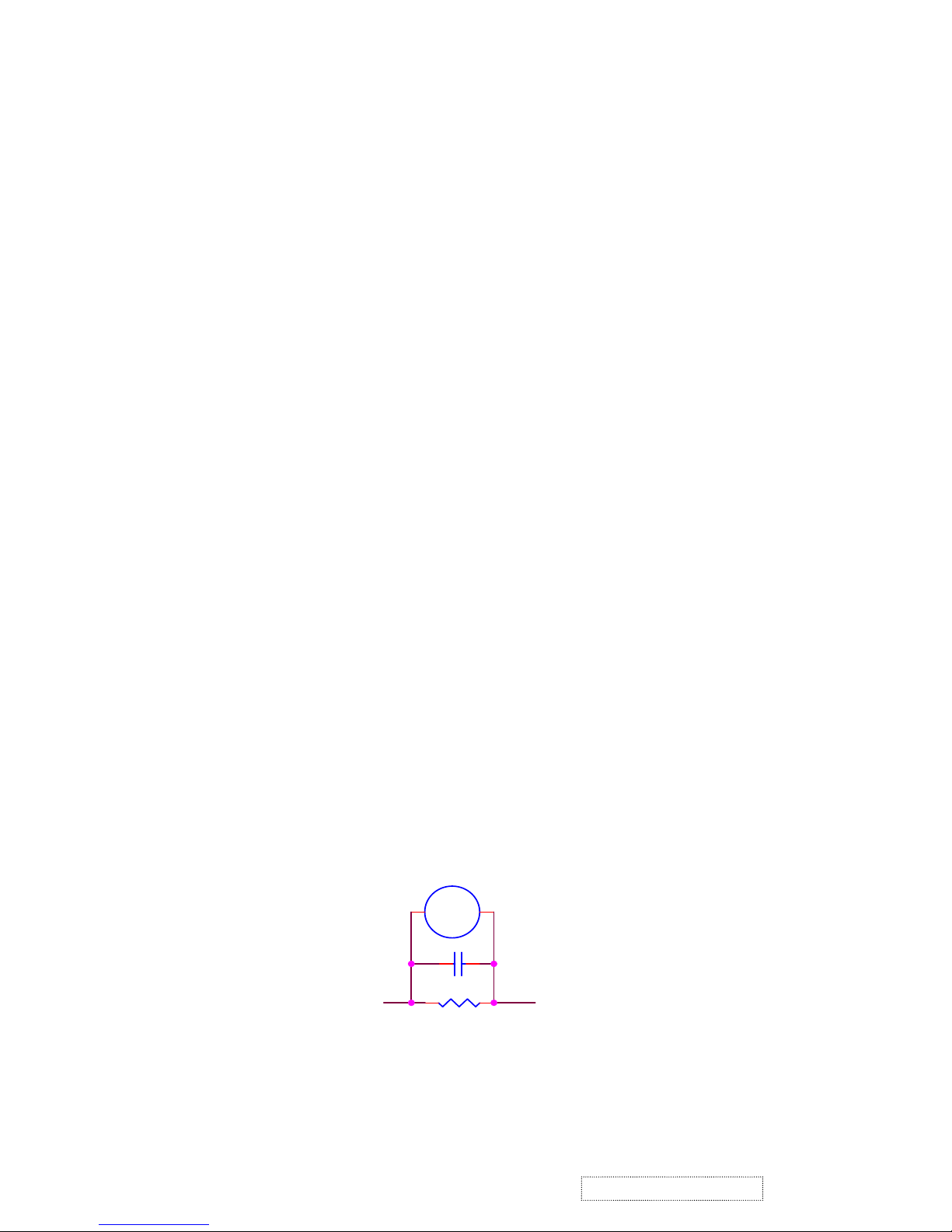
4. LEAKAGE CURRENT HOT CHECK
4-1 Plug the AC cord directly into the AC outlet. Do not use an isolation transformer during this check.
4-2 Connect a 1500 ohm, 10 watt resistor, paralleled by a 0.15uF capacitor between each metallic part
and a good earth ground.
4-3 Use an AC voltmeter with 1000 ohm / volt or more sensitivity and measure the AC voltage across
the combination 1500 ohm resistor and 0.15uF capacitor.
4-4 Move the resistor connection to each exposed metallic part and measure the voltage .
4-5 Reverse the polarity of the AC plug in the AC outlet and repeat the above measurement.
4-6 Voltage measured must not exceed 1.5 volt RMS, from any exposed metallic part to the ground. A
leakage current tester may be used in the above hot check, in which case any circuit measured must
not exceed 1.0 milliamp. In the case of a measurement exceeding the 1.0 milliamp value, a
rework is required to eliminate the chance of a shock hazard.
To Metal Parts
V
AC VOLTMETER
1500 10W
0.15u
.
Earth Ground
1. Precautions and Safety Notices
ViewSonic Corporation
1
Confidential – Do Not Copy
VG700b-2

Mechanical:
Dimension ( W x H x D ) mm
Set: a. with stand
410.0 x 433 x 180 mm
b. Without stand
410.0 x 433 x 58.4 mm
Base (L X W) 290 x 180 mm
Pa
cking : ( W x H x D ) mm
472 x 515 x 216 mm
Weight: Net / Gross ( Kg ) 4.5 / 6.9
Wall Mount (VESA) 100 x 100 mm
LCD Panel type QDI / QD17EL07
Max. Resolution (HxV)
1280 x 1024
Nominal picture size (HxV 338 mm x 270 mm
Display colors 16.2 M ( 6 bit + dithering)
Dot pitch
0.264 mm
Response time 4 +16 / 20ms (Tr + Tf / typical)
Brigh
tness (100% white) Typical: 300 cd/m² , Min. 240cd/m²
Contrast
Typical: 450:1, Min. 300:1
Viewing angle 75 / 75 /65 / 60 (L/R/T/B CR>=10)
Synchronization Fh = 31~82 KHz / Fv=50~75Hz
Presets 18 timing modes
OSD Language
8 language
Color Temperature sRGB , 6500°K (default) / 9300°K
/5400°K / User R,G,B
Plug & Play DDC1/2B interface
Scalar chip Genesis gm2121 AD
Audio Input Connector 3.5 mm Stereo, PC2001
Audio Amplifier 3W x 2 (chip :TPA3002D2)
AC Power range 90 V ~ 264 V, 50 Hz / 60 Hz
Power consumption < 48W green / < 3W amber
(On / O
ff mo de)
2. Specification
ViewSonic Corporation
2
Confidential – Do Not Copy
VG700b-2
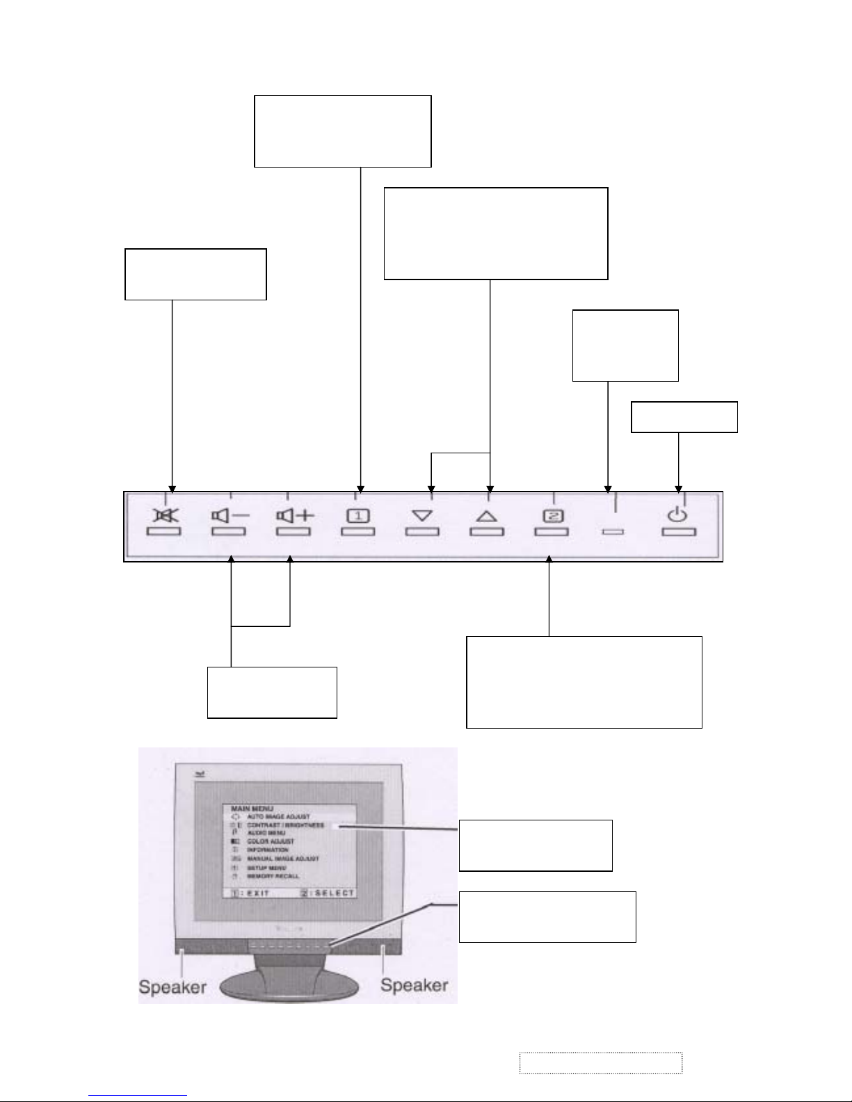
Scrolls through menu options and
adjusts the displayed control.
Also a shortcut to display the
Contrast adjustment control screen.
Displays the control screen for the
highlighted control. Also toggles
between two controls on some screens.
Also a shortcut to auto image adjust
Displays the Main Menu or
exits the control screen
and saves adjustments.
Temporarily silence
audio output
Decreases or
increases volume
Power light
Green = ON
Orange=power
Power On / Off
Main Menu
With On Vi ew controls
Front Control Panel
shown below in detail
3. Front Panel Function Control Description
ViewSonic Corporation
3
Confidential – Do Not Copy
VG700b-2

Main Menu Controls
Adjust the menu items shown below by using the up and down buttons.
A. Auto Image Adjust automatically sizes, centers, and fine tunes the video signal to eliminate waviness and
distortion. Press the [2] button to obtain a sharper image.
NOTE: Auto Image Adjust works with most common video cards. If this function does not work on your
LCD display, then lower the video refresh rate to 60 Hz and set the resolution to its pre-set value.
B. Contrast adjusts the difference between the image background (black level) and the foreground (white
level).
C. Brightness adjusts the lamps current to control the screen brightness.
D. Audio Menu
controls are explained below:
Volume increases the volume, decreases the volume, and mutes the audio.
Mute temporarily silences audio output.
E. Color Adjust
provides several color options: preset color temperatures and Custom User Color which allows
you to adjust red (R), green (G), and blue (B). The factory setting for this product is 6500 K (6500° Kelvin).
9300K — Adds blue to the screen image for cooler white (used in most office settings with fluorescent
lighting).
5400K — Adds red to the screen image for warmer white and richer red.
Custom User Color — Individual adjustments for red, green, and blue.
1 To select color (R, G or B) press button [2].
2 To adjust selected color, press or .
3 When you are finished making all color adjustments, press button [1] twice.
F. Information displays the timing mode (video signal input) coming from the graphics card in your computer.
See your graphic card’s user guide for instructions on changing the resolution and refresh rate (vertical
frequency). VESA 1280 x 1024 @ 60 Hz (recommended) means that the resolution is 1280 x 1024 and the
refresh rate is 60 Hertz.
G. Manual Image Adjust
controls are explained below:
H. Size (Horizontal Size) adjusts the width of the screen image.
NOTE: Vertical size is automatic with your LCD display.
H./V. Position adjusts horizontal and vertical position of the screen image. You can toggle between
Horizontal and Vertical by pressing button [2]. Horizontal moves the screen image to the left or to the right.
Vertical moves the screen image up and down.
Fine Tune sharpens focus by aligning the illuminated text and/or graphic characters.
Sharpness adjusts the clarity and focus of the screen image.
Setup Menu controls are explained below:
Language allows you to choose the language used in the menus and control screens.
Resolution Notice displays the recommended resolution for this LCD display.
Enable allows the Resolution Notice to appear on-screen.
Disable will not allow the Resolution Notice to appear on-screen.
OSD Timeout sets the length of time an on-screen display scr een is displayed. For example, with a“15
second” setting, if a control is not pushed within 15 seconds, the display OSD
disappears.
H. OSD Position allows you to move the on-screen display menus and control screens.
I. M emory Recall
return s adjustments to the original factory settings if the display is operating in a factory
Preset Timing Mode listed in this user guide.
ViewSonic Corporation
4
Confidential – Do Not Copy
VG700b-2
4-1. Outline
1.1 POWER On/Off , LED, Button"2" , Up arrow- button , Down arrow button , Button"1" , button , Down
arrow button , Button"1" , on the front panel.
1.2 Video signal connector, audio line-in receptacle and DC-IN are located on the back side of the cabinet .
1.3 OSD menu includes the following function;
AUTO IMAGE ADJUST
CONTRAST / BRIGHTNESS
AUDIO MENU
COLOR ADJUST
INFORMATION
MANUAL IMAGE ADJUST
SETUP MENU
MEMORY RECALL
1.4 CONTRAST and BRIGHTNESS can be directly controlled with UP / DN key.
1.5 Speaker out can be controlled with + / - volume key and MUTE key.
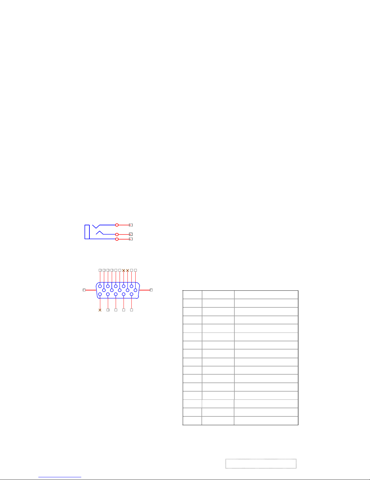
4-2. CONNECTORS
2.1 AC inlet : CEE22 typed connector
2.2 Audio : Line-in receptacle
2.3 Video signal connector 15P Mini D-Sub
PIN
MNEMONI SIGNA
L
1
RV
Red Video
2
GV
Green Video
3
BV
Blue Video
4
N
C
N
one
5
GND
Ground(DDC return
)
6
RG
Red GND
7
GG
Green GND
8
BG
Blue GND
9
+5V
+ 5V (for DDC
)
10
SG
Sync GND
11
N
C
N
one
12
SD
A
DDC Data
13
HS
Horizontal Sync
14
VS
Vertical Sync
15
SC
L
DDC Clock
J1
PHONEJACK STEREO
1
2
3
CN6
DB15HD
1
6
2
7
3
8
4
9
5
11
12
13
14
15
10
16
17
!
4. Circuit Description
ViewSonic Corporation
5
Confidential – Do Not Copy
VG700b-2
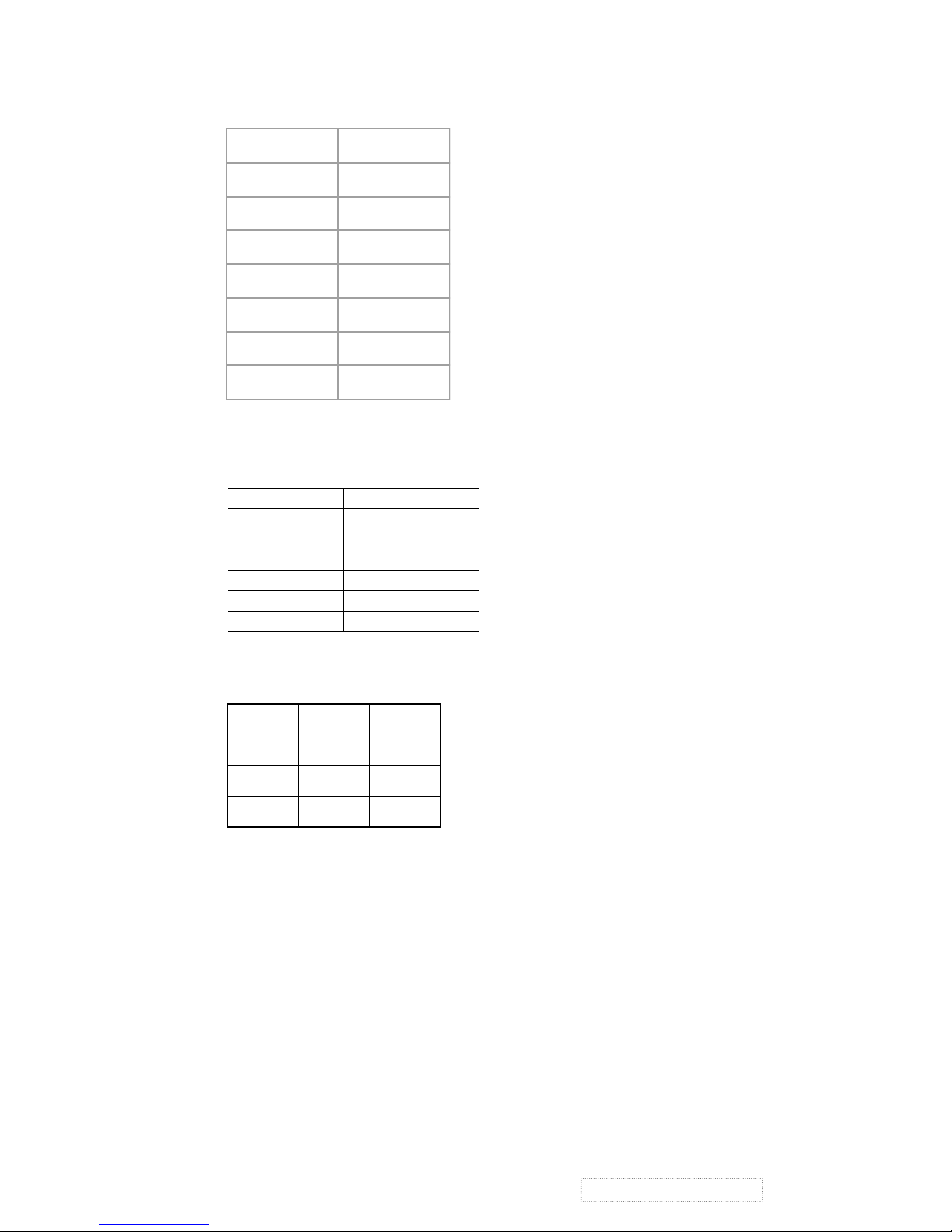
4-3. ELECTRICAL SPECIFICATIONS
3.1 Standard cond itions
3.2 POWER
3.2.1 Power supply
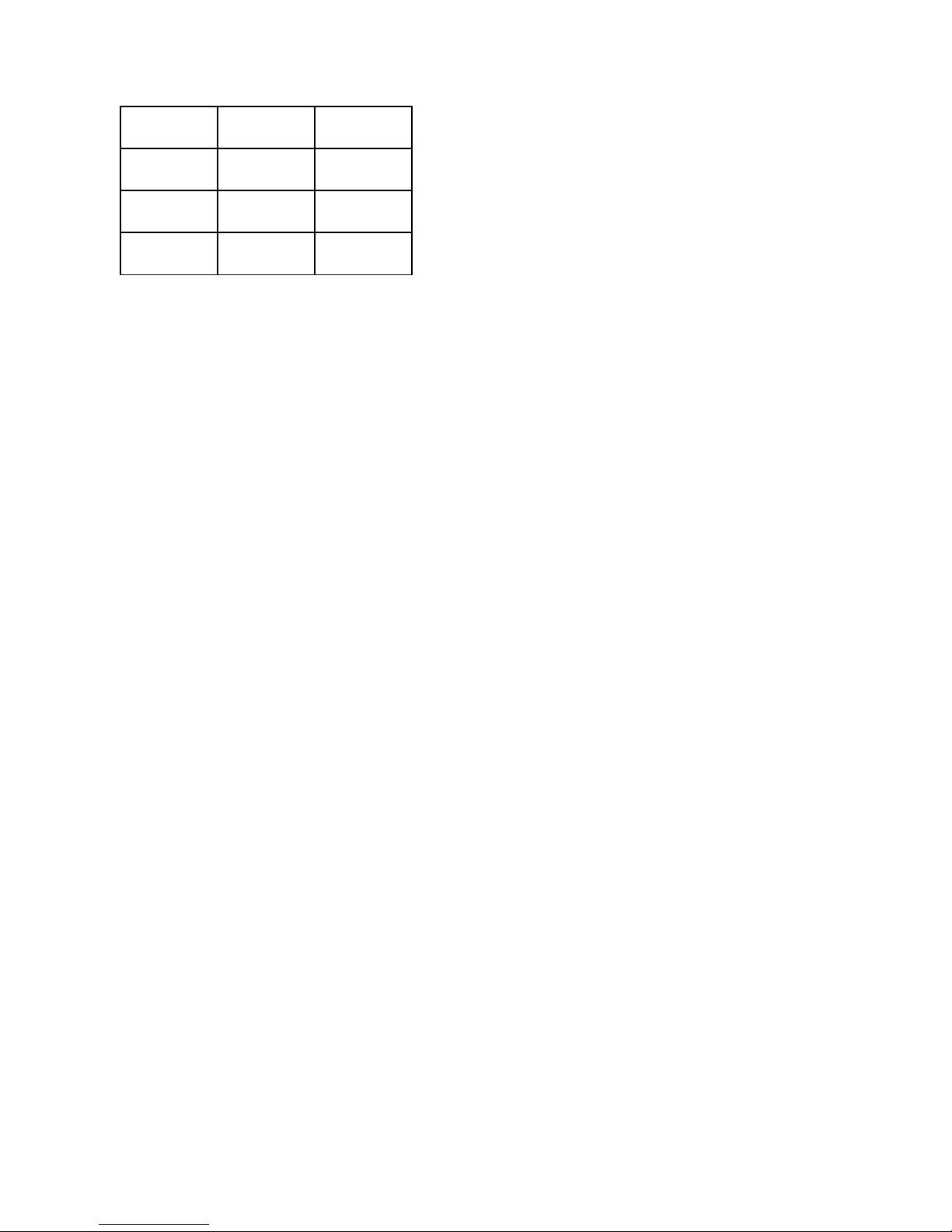
3.2.2 Power Management
3.3 Acceptable timing
If your timing is within following specification, this LCD display can automatically function with a certain
position.
Horizontal: Sync frequency: 30~81 kHz
Vertical: Sync frequency: 56~75Hz
Input voltage
90~240 Volts
Power frequency
50 / 60 Hz, +/-3 Hz
Input current
< 1.5 Arms @90Vac
< 0.75Arms @265Vac
Inrush current
90A(Max) at 230Vac
Power consumption
48W(Max)
Output V oltage
@0-4.8A Load 12Vdc+/- 5%
Display area 338 x 270
Video s ignal 0.7 Vpp
Contrast Max.
Brightness Max.
Am bien t 20 +/- 5 C
Input AC
Warming up > 30
Display 1280 x1024
3.4 Signal level and input impedance
3.4.1 Video Signal level This LCD display is adjusted at the factory using 0, 7 Vp-p Video signal.
3.4.2 Sync Signal level
H/V Separate: TTL level
3.4.3 Input impedance
Video input: 75 ohms
Sync input: > 1 k ohms
ViewSonic Corporation
6
Confidential – Do Not Copy
VG700b-2
State Power Indicator
On 48Watts Green
Standby <3Watts Amber
Off <3Watts None
State Power Indicator
On 48Watts Green
Standby <3Watts Amber
Off <3Watts None

4-4. SIGNAL CABLE: Signal cable with Mini D-Sub 15P connectors at both ends. Length: 1.8 meter.
4-5 .
EDID data
Analog EDID
Time: 09:08:54
Date: Wed Sep 04, 2002
______________________________________________________________________
______________________________________________________________________
VIEWSONIC CORPORATION
EDID Version # 1, Revision # 3
DDCTest For: VSC VG700b-2
______________________________________________________________________
______________________________________________________________________
60 | 2A 40 30 70 13 00 52 0E 11 00
70 | 00 1E 00 00 00 FF 00 41 31 4B
80 | 30 33 30 31 30 30 30 30
31
0A
90 | 00 00 00 FD 00 32 4B 1E
52
0
E
100 | 00 0A 20 20 20 20 20 20
00
00
110 | 00 FC 00 56 47 37 30 30
62
2D
120 | 32 0A 20 20 20 20 00 86
_________________________________________________ ___________________
(08-09) ID Manufacturer Name = VSC
(10-11) Product ID Code (Non-Alphanumerical) = B50B - (46347)
(12-15) Last 5 Digits of Serial Number = NOT SPECIFIED
(16) Week of Manufacture = 01
(17) Year of Manufacture = 2003
(10-17) Complete Serial Number = NOT SPECIFIED
(18) EDID Structure Version Number = 1
(19) EDID Structure Revision Number = 3
(20) VIDEO INPUT DEFINITION : =
Separate Sync, Analog signal, 0.700V/0.300V (1.000 Vp-p)
(21) Maximum Horizontal Image Size = 340mm
(22) Maximum Vertical Image Size = 270mm
(23) Display Gamma = 2.20
(24) DPMS Supported Feature: = Active Off.
Display type = RGB color display
(25-34) CHROMA INFO:
Red x = 0.633 Green x = 0.300 Blue x = 0.146 White x = 0.313
Red y = 0.336 Green y = 0.586 Blue y = 0.103 White y = 0.329
ViewSonic Corporation
7
Confidential – Do Not Copy
VG700b-2

(35) ESTABLISHED TIMING I:
720 x 400 @ 70Hz (VGA, IBM)
640 x 480 @ 60Hz (MAC II, Apple)
640 x 480 @ 67Hz (VESA)
640 x 480 @ 72Hz (VESA)
640 x 480 @ 75Hz (VESA)
800 x 600 @ 56Hz (VESA)
800 x 600 @ 60Hz (VESA)
(36) ESTABLISHED TIMING II:
800 x 600 @ 72Hz (VESA)
800 x 600 @ 75Hz (VESA)
832 x 624 @ 75Hz (MAC II, Apple)
1024 x 768 @ 60Hz (VESA)
1024 x 768 @ 70Hz (VESA)
1024 x 768 @ 75Hz (VESA)
1280 x 1024 @ 75Hz (VESA)
(37) Manufacturer's Reserved Timing:
1152 x 870 @ 75Hz (MAC II, Apple)
(38-53) Standard Timing Identification:
#1: 1280 x 1024 @ 60Hz
#2: (40) not specified
#3: (42) not specified
#4: (44) not specified
#5: (46) not specified
#6: (48) not specified
#7: (50) not specified
#8: (52) not specified
(54-71) Detail Timing Description #1: 1280x1024 Pixel Clock=108.0MHz
--------------------------------------------------------------------------------
------------------------------------------------------------------------------- Horizontal Image Size=338mm Vertical Image Size=270mm
Refresh Mode: Non-Interlaced Normal display, no stereo
HORIZONTAL:
Active Time = 1280 pixels Blanking Time = 408 pixels
Sync Offset = 48 pixels Sync Pulse Width = 112 pixels
Border = 1 pixels Frequency = 64.0 kHz
!
ViewSonic Corporation
8
Confidential – Do Not Copy
VG700b-2
 Loading...