

Page 1

Service Manual
ViewSonic VG700b
Model No. VLCDS23719-3W
17” Color TFT LCD Display
ViewSonic
(VG700b-1_SM_604 - Rev. 1a – Oct 2002)
381 Brea Canyon Road, Walnut, California 91789 USA - (800) 888-8583
Page 2
Copyright
Copyright
reproduced, transmitted, transcribed, stored in a retrieval system, or translated into any language or
computer language, in any form or by any means, electronic, mechanical, magnetic, optical, chemical,
manual or otherwise, without the prior written permission of ViewSonic Corporation.
Disclaimer
ViewSonic makes no representations or warranties, either expressed or implied, with respect to the
contents hereof and specifically disclaims any warranty of merchantability or fitness for any particular
purpose. Further, ViewSonic reserves the right to revise this publication and to make changes from time
to time in the contents hereof without obligation of ViewSonic to notify any person of such revision or
changes.
Trademarks
ViewSonic is a registered trademark of ViewSonic Corporation.
All other trademarks used within this document are the property of their respective owners.
2002 by ViewSonic Corporation. All rights reserved. No part of this publication may be
¤
Revision History
Revision Date Description Of Changes Approval
1a 10/23/02 Initial Release DCN-2660 C. Shen
ViewSonic Corporation
ii
Confidential – Do Not Copy
VG700b
Page 3

Preface
This manual is prepared for the maintenance service for the VG700b series Flat
Panel Monitor. Maintenance procedures described in this manual are intended to isolate
faulty parts and replace them in the field. It also aims to serve as a guide in procuring
replacement parts for this product.
This manual is copyrighted and all rights are reserved. This product may not, in
whole or in part be copied, photocopied, translated or reduced to any electronic or
machine readable form without prior written consent except for copies retained by the
purchaser for backup purpose.
This manual includes system overview, major system assembly, components
description, and the Troubleshooting makes explanations on how to detect errors. It
also includes a flow chart for checking or correcting faults.
No Warranty or representation, either expressed or implied, is made with
respect to this documentation, its quality, performance, merchantability or fitness
for particular purpose.
No event will the vendor be liable for direct, indirect, special, incidental or
consequential damages arising out of the user or inability to use this product or
documentation.
Notice:
The information found in this manual is subject to change without prior notice. Any subsequent
changes made to the data herein will be incorporated in future edition.
ViewSonic Corporation
iii
Confidential – Do Not Copy
VG700b
Page 4

Table of Contents
Chapter 1 Introduction 1-1
1-1 The Appropriate Operation 1-1
1-2 Product Highlight 1-2
1-3 Technical Specification 1-2
Chapter 2 Mechanical Construction 2-1
2-1 Package Overview 2-1
2-2 Exploded Overview 2-3
Chapter 3 Procedure of Disassembly 3-1
3-1 Disassembly of Stand Unit and Main Body 3-1
3-2 Disassembly of Control Board, Cosmetic Cap and Front Cover 3-2
3-3 Disassembly of LCD Panel and Main Board 3-3
3-4 Disassembly of Support Bracket, Speakers and all wires 3-4
Chapter 4 Function of Boards 4-1
4-1 Main Board 4-1
4-2 Control Board 4-4
4-3 Inverter Board 4-5
Chapter 5 Troubleshooting Procedure 5-1
5-1 Equipment Needed 5-1
5-2 Main Procedure 5-1
ViewSonic Corporation
v
Confidential – Do Not Copy
VG700b
Page 5

Chapter 6 Function Test and Alignment Procedure 6-1
6-1 Product and Test Equipment 6-1
6-2 Hot Key (Service Function) 6-1
6-3 Test Condition 6-1
6-4 Test Display Modes & Pattern 6-2
6-5 Function Test and Alignment Procedure 6-5
6- 6 Cleaning 6- 7
6-7 Inspection Standard 6-7
Chapter 7 Firmware Upgrade Procedure 7-1
7-1 Equipment Needed 7-1
7-2 Hardware Setup Procedure 7-2
7-3 Firmware Upgrade Procedure 7-2
Chapter 8 EDID Update Procedure 8-1
8-1 Equipment Needed 8-1
8-2 Hardware Setup Procedure 8-2
8- 3 DDC Keyin Procedure 8- 2
Chapter 9 Panel Specification 9-1
9-1 LCD Panel [Model#M170EN04]
9-1
Chapter 10 Packing for Shipping 10-1
10-1 Package 10-1
Chapter 11 Appendix 11-1
11-1 The Serial Number System Definition 11-1
Chapter
Chapter
Chapter
1
2 Schematic Diagrams
3
PCB Layout
1
1
Complete parts list
4
12-1~12-
13-1~13-
14-1~14-5
7
3
ViewSonic Corporation
vi
Confidential – Do Not Copy
VG700b
Page 6

Chapter 1 Introduction
This manual provides an integral technical information you need to maintain the
LCD Monitor. And this manual is applied to the model of 1280*1024 pixels color TFT LCD
Monitor with a 17 flat panel screen.
This manual is for the technicians and people who have the electronic background.
Send the product back to the distributor for repairing and do not attempt to do anything
which is complex or not mentioned in the troubleshooting.
1-1 The Appropriate Operation
VG700b series
Turn off the Product before cleaning.
Ɣ
VG700b Series Service Manual
Ɣ
Use only a dry soft cloth when cleaning the LCD panel surface.
Use a soft cloth moistured with mild detergent to clean the display housing.
Ɣ
Ɣ
Use only high quality and safety approved AC/DC power Adapter.
Disconnect the Power Plug from AC outlet if the Product is not used for a long
Ɣ
period of time.
Ɣ
Do not touch the LCD panel surface with sharp or hard objects.
Ɣ
Do not use abrasive cleaners, waxes or solvents for your cleaning.
Do not operate the product under the following conditions:
* Extremely hot, cold or humid environment.
* Areas susceptible to excessive dusts and dirt
* Near any applicance generating a strong magnetic field.
* Place in direct sunlight.
ViewSonic Corporation
Confidential – Do Not Copy
1-1
VG700b
Page 7

1-2 Product Highlight
Ɣ
Analog signal input
Ɣ
Active matrix TFT LCD technology
1280*1024 addressable pixels, 60Hz
Ɣ
Ɣ
30-82kHz Horizontal Frequency
VG700b Series Service Manual
50-75Hz Vertical Refresh Rate
Ɣ
Auto Image Adjustment
Ɣ
Ɣ
Multifunction OSD user controls
VESA DPMS Power saving
Ɣ
Resolution Compatibility: 640*350, 640*480, 720*400, 800*600,
Ɣ
832*624, 1024*768, 1152*870, 1280*1024
1-3 Technical Specification
I.) AU Panel:(M170EN04)
Active matrix TN TFT color LCD
Ɣ
17 diagonal screen size
Ɣ
1280*1024 addressable pixels
Ɣ
0.264mm * 0.264mm pixel pitch
Ɣ
8
2 0 cd/m2 (max),brightness,
Ɣ
40:1 (max) contrast ratio,
5
Ɣ
250 cd/m
400:1(typ),
2
(typ),
250:1(min)
0
2 0 cd/m
2
(min)
VG700b series
1-2
Ɣ
Lamp number : 4 CCFLs edge-light (2 top/2 bottom)
Ɣ
Backlight Life: 50,000 hrs (Typical), 30,000 hrs (Min.)
Active Size 337.92mm(H)*270.34mm(V)
Ɣ
ViewSonic Corporation
Confidential – Do Not Copy
VG700b
Page 8

II.) Power Supply
Ɣ
Input Voltage Range: 90 to 265 VAC
Ɣ
Input Frequency Range: 47 to 63 Hz
Ɣ
Output Voltage@0-3.58A Load: 12V DC +/- 5%
Ɣ
Over Current Protection 4A Typical at 12VDC
Ɣ
Power Dissipation 40 Watts(Max.)
III.) Audio
VG700b series
IV.) y Preset Modes
Ɣ
Line Input Connection 3.5mm Stereo Jack
Ɣ
Line Input Signal 1.0Vrms
Ɣ
Maximum Power Output 3W@ <8% Distortion
Ɣ
VGA 640*350@70Hz (25.176MHz)
Ɣ
VESA 640*480@60Hz (25.175MHz)
Ɣ
MAC 640*480@67Hz (31.500MHz)
Ɣ
VESA 640*480@72Hz (31.50MHz)
Ɣ
VESA 640*480@75Hz (31.50MHz)
Ɣ
VESA 720*400@70Hz (28.320MHz)
Ɣ
VESA 800*600@56Hz (36.00MHz)
VG700b Series Service Manual
Ɣ
VESA 800*6.00@60Hz (40.00MHz)
Ɣ
VESA 800*600@72Hz (50.00MHz)
Ɣ
VESA 800*600@75Hz (49.5MHz)
MAC 832*624@75Hz (57.272MHz)
Ɣ
Ɣ
VESA 1024*768@60Hz (65MHz)
Ɣ
VESA 1024*768@70Hz (75.000MHz)
Ɣ
VESA 1024*768@72Hz (78.000MHz)
Ɣ
MAC 1024*768@75Hz (80.000MHz)
ViewSonic Corporation
Confidential – Do Not Copy
1-3
VG700b
Page 9

Ɣ
VESA 1024*768@75Hz (78.750MHz)
Ɣ
MAC 1152*870@75Hz
Ɣ
VESA 1280*1024@60Hz
Ɣ
VESA 1280*1024@70Hz
Ɣ
VESA 1280*1024@75Hz
V.) Mechanical & Environmental Condition
VG700b Series Service Manual
Ɣ
Width*Height*Depth: 410.0mm*421.4mm*191.2mm
Ɣ
Monitor Weight: 5.2kgs/11.4lbs
Ɣ
Operating Temperature: 00C to +400C
Ɣ
Storage Temperature: -200C to +600C
Ɣ
Operating Relative Humidity: 10% to 95% Non-Condensing
Ɣ
Storage Relative Humidity: 10% to 95% Non-Condensing
VG700b series
1-4
ViewSonic Corporation
Confidential – Do Not Copy
VG700b
Page 10
Chapter 2 Mechanical Construction
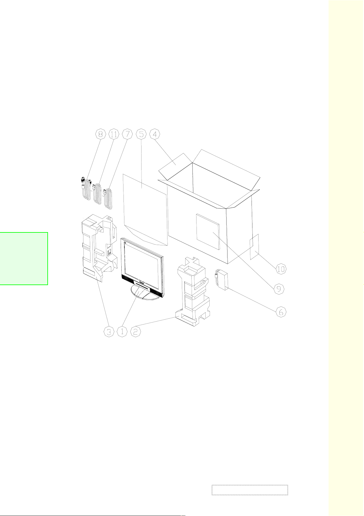
2-1 Package Overview
VG700b series
VG700b Series Service Manual
ViewSonic Corporation
Confidential – Do Not Copy
2-1
VG700b
Page 11
2-1.1 Replacement Parts List
(NA)
(
(
)
ITEM VIEWSONIC P/N P/N DESCRIPTION
1 DC.58302.001
2 P-FM-0602-0752 56.58301.001 CUSHIONS R EPS VG700
3 P-FM-0602-0753 56.58302.001 CUSHIONS L EPS VG700
4 P-BX-0601-0748 55.58301.002 CARTON AB VG700B
VG700 LCD DISPLAY;
"VIEWSONIC",AU-M170EN05,USA
5 M-MS-0808-8141 51.00081.002
6 A-AD-0114-0149 47.58301.001
7 A-AU-0120-0032 42.59903.001
8 A-VC-0101-0266 42.56908.001
9 A-CD-VG750 36.58302.002
PE BAG LDPE 540*750*0.04t
W/HOLE
ADAPTER IN:100-240V
OUT:12V/3.33A;LSE
CABLE AUDIO 1.8M LM/BK/LM
VX2000
CABLE VGA 15P 1800mm 2 CORE
PV870C
USER'S GUIDE
MULTILINGUAL+CD+TCO'95 ECO
10 M-LB-0813-0706 35.58203.001 LABEL CARTON 76*76mm
11-1 A-PC-0106-0188 42.57207.001
11-2 A-PC-0106-0190 42.50116.002
11-3 A-PC-0106-0187 42.50126.001
12-1 M-MS-0808-8353 36.58307.001
12-2 M-MS-0808-8409 36.58303.001
CABLE POWER CORD 1.8M 0.1M
UNSHIELD
CABLE POWER CORD 1830mm
JPB) BLACK
CABLE POWER CORD 1.8M 0.1M
CHINA
WARRANTY CARD S. CHINESE
VIEWSONIC
WARRANTY CARD JAPAN
VIEWSONIC
13 M-LB-0813-0736 35.58304.001 LABEL BARCODE 40*14 Viewsonic
14-1 M-LB-0813-0737 36.58308.001 WARRANTY STICKER S. CHINESE
14-2 M-LB-0813-0738 36.58304.001
15 M-MS-0808-8410 36.58305.001
16-1 M-MS-0808-8411 36.58306.001
16-2 M-LB-0813-0739 36.58309.001
2-2
ViewSonic Corporation
WARRANTY STICKER JAPAN
VIEWSONIC
ENVELOPE FOR WARRANTY
CARD JAPAN VIEWSONIC
SHIPPING BAG FOR WARRANTY
KIT JAPAN VIEWSONIC
SHIPPING WARRANTY STICKER
S. CHINESE VIEWSONIC
Confidential – Do Not Copy
VG700b
Page 12
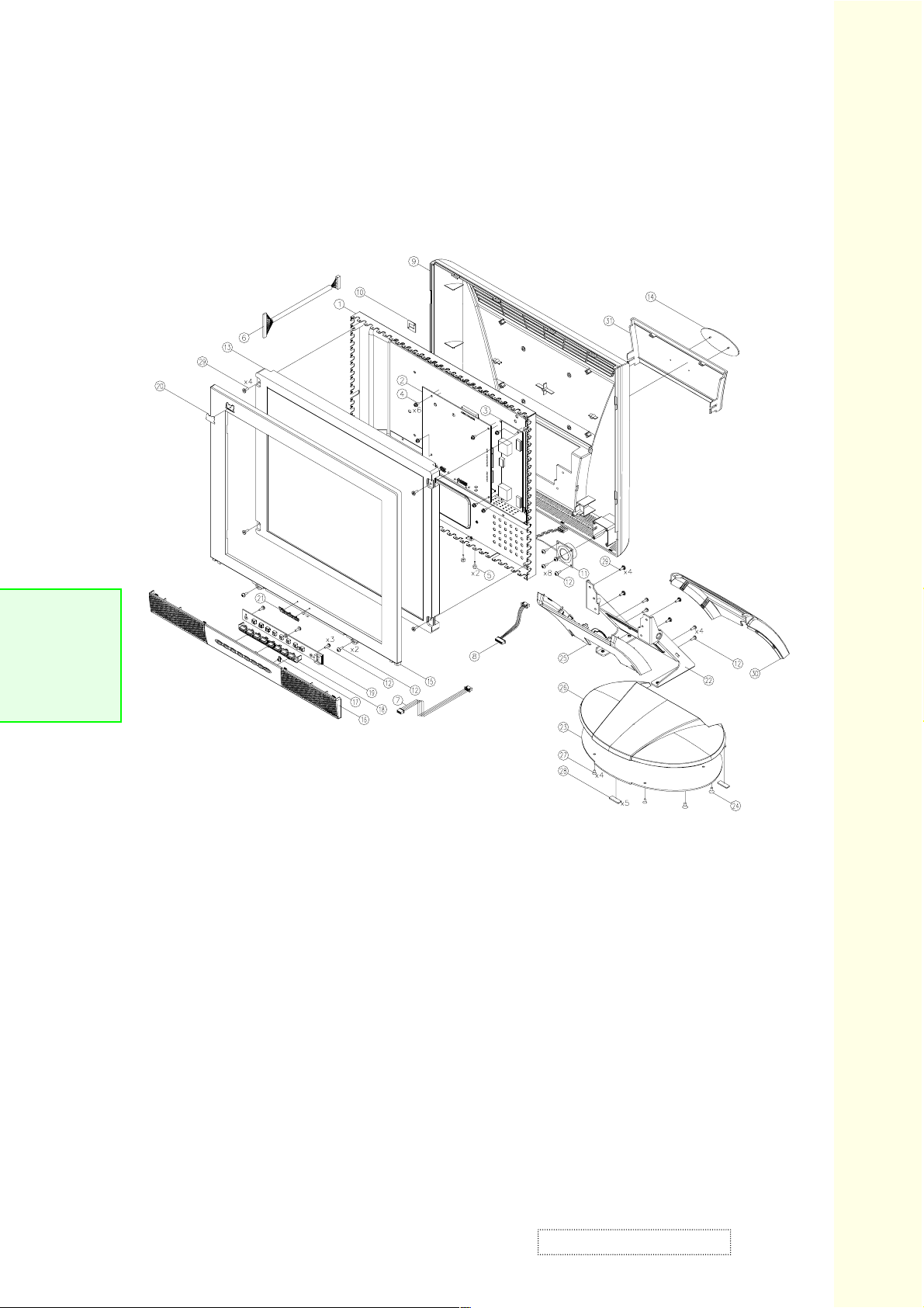
2-2 Exploded Overview
VG700b series
VG700b Series Service Manual
ViewSonic Corporation
Confidential – Do Not Copy
2-3
VG700b
Page 13
2-2.1 Replacement Parts List
ITEM VIEWSONIC P/N DESCRIPTION P/N
1 SUPPORT BRKT SECC 0.8t VG700(ADT) 61.58301.001
2 B-MB-0201-0671 PCBA MAIN BD VG700 80.58301.001
3-1 B-SB-0221-0448 PCBA INVERTER LI2113 LIEN CHANG 44.58301.001
3-2 B-SB-0221-0447 PCBA INVERTER PLCD2417414 EMAX 44.58302.001
4 M-SCW-0824-0651 SCREW PAN MECH W/SF M3*6 Ni 85.1F123.060
5 M-MS-0808-6287 SCREW HEX I/O #4-40*H5*L7.5 Ni NYLOK 85.005AG.075
6 M-WR-0828-0644 W.A. 30P UL20276 #28 200mm+CORE 42.58302.001
7 M-WR-0828-0632 W.A. 12P UL1571 #28 260mm (MB TO CRTL) 42.58203.001
8 M-WR-0828-0636 W.A. 10/6P UL1007 #1007 #24 100mm VG700(INV 42.58301.001
9 C-BC-0302-0442 REAR COVER ABS HB-VS08 VG700b 51.58302.002
10 LOCK BRKT TINPLATE 0.5t PV880 61.56005.002
11 E-SK-0412-0049 ASSY SPEAKER MODULE MEI SHAN HB34 49.58301.001
12 SCREW M3*7 85.UA123.070
13 M-LCD-0826-0120 TFT LCD 1280*1024 17" ADT L170E3 PANEL 48.56902.001
14 NAMEPLATE ELLIPSE Viewsonic 51.58711.001
15 C-FP-0301-0901 FRONT COVER ABS HB-VS08A;VG700b 51.58301.002
16 M-MS-0808-8297 COSMETIC CAP ABS HB-VS08;VG700b 51.58303.002
17 M-MS-0808-8176 LED LENS ACRYLIC VG500 51.58207.001
18 PL-NB-0707-0172 SELECT KNOB ABS CS-VS07A VG500 51.58206.001
19 B-CB-0206-0135 PCBA CTRL BD VG500 80.58202.001
20 M-LB-0830-0695 BIRD LOGO AL E015-001 Viewsonic 35.58202.001
21 Viewsonic AL-LOGO 35.90305.001
22 M-MS-0808-8145 HINGE TILT SPHC 2.0t VG700/750 61.58302.001
23 M-MS-0808-8146 BASE PLATE SGCC 2.0t VG700/750 61.58303.001
24 M-SCW-0824-0658 SCREW FLAT MECH M4*8 Ni 85.4A124.080
25 M-MS-0808-8300 FRONT ARM ABS HB-VS08 VG700b 51.58312.002
26 M-CV-0830-2343 BASE COVER ABS HB-BS08 VG700b 51.58311.002
27 M-SCW-0824-0660 SCREW FLAT TAP M3*6 Ni 85.YA123.060
28 PL-PD-0714-0064 RUBBER FOOT 25*10*1.2t 52.00003.001
29 M-SCW-0824-0608 SCEW WCH/W MECH M3*10 Ni 85.ZA123.100
30 M-MS-0808-8302 REAR ARM ABS HB-VS08 VG700b 51.58313.002
31 M-MS-0808-8301 HINGE CAP ABS HB-VS08 VG700b 51.58304.002
2-4
ViewSonic Corporation
Confidential – Do Not Copy
VG700b
Page 14
Chapter 3 Procedure of Disassembly
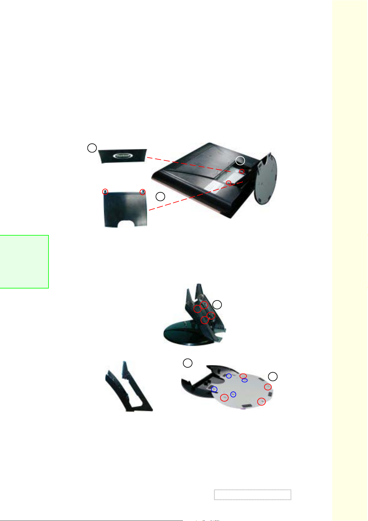
3-1 Disassembly of Stand Unit and Main Body
Hinge Cap
1
Main Unit
2
Rear Arm
1
VG700b series
1. Lay VG700b Monitor face down to take off Rear Arm and Hinge Cap.
VG700b Series Service Manual
2. Unscrew the four screws to remove the Stand and Main Unit.
Stand Unit
4
Hinge Tilt Unit
3
Base Cover
Base Plate
3. Unscrew the four screws to remove the Hinge Tilt and Base Unit.
5
4. Unscrew the four screws on Hinge Tilt unit to remove the Front Arm and Hinge Tilt.
5. Unscrew the four screws on the Base Unit to the Base Cover and Base Plate.
ViewSonic Corporation
remove
Confidential – Do Not Copy
VG700b
3-1
Page 15
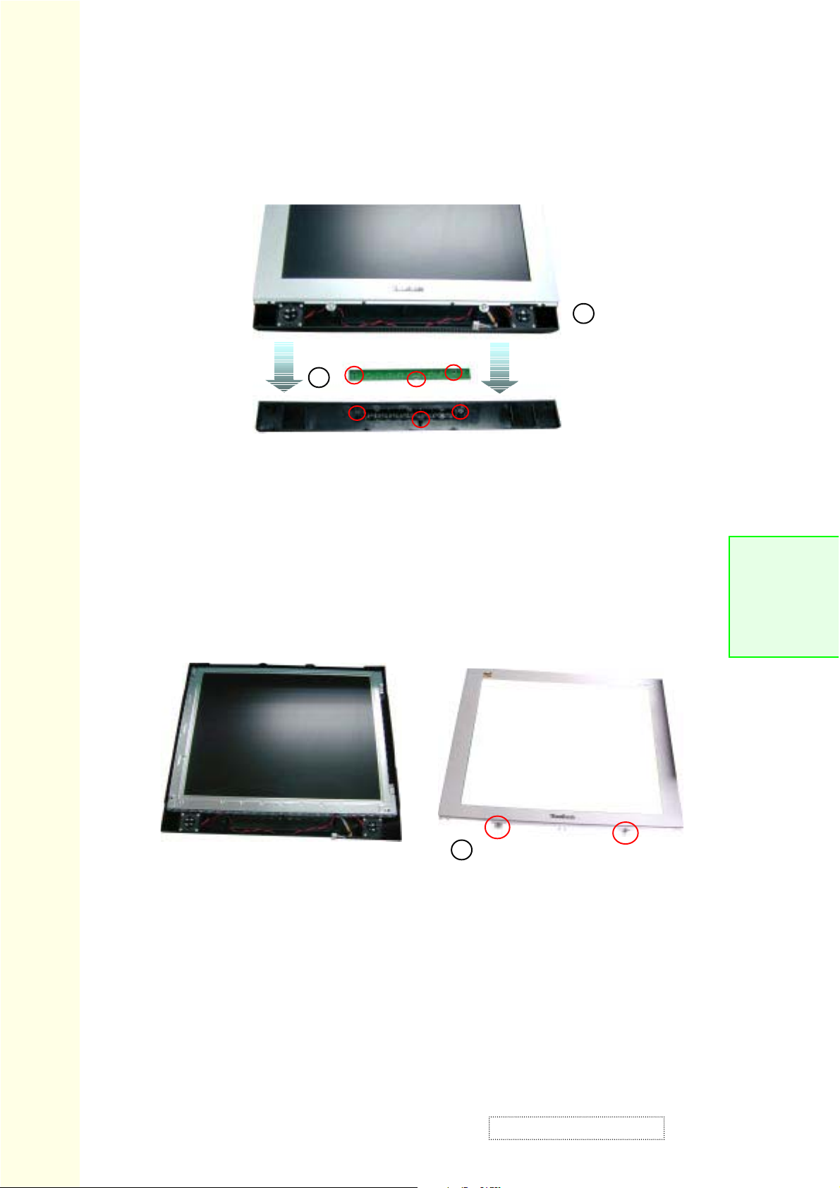
3-2 Disassembly of Control Board, Cosmetic Cap and Front Cover
Control Board
VG700b Series Service Manual
1. First turn over the monitor, and press the two sides from up to down
to remove the Cosmetic Cap.
2
Cosmetic Cap
1
VG700b series
2. Unplug the Control Wire and unscrew the three screws to remove
the Control Board.
Main Unit
3. Unscrew the two screws of Front Cover to remove it from Main Unit.
3
Front Cover
3-2
ViewSonic Corporation
Confidential – Do Not Copy
VG700b
Page 16
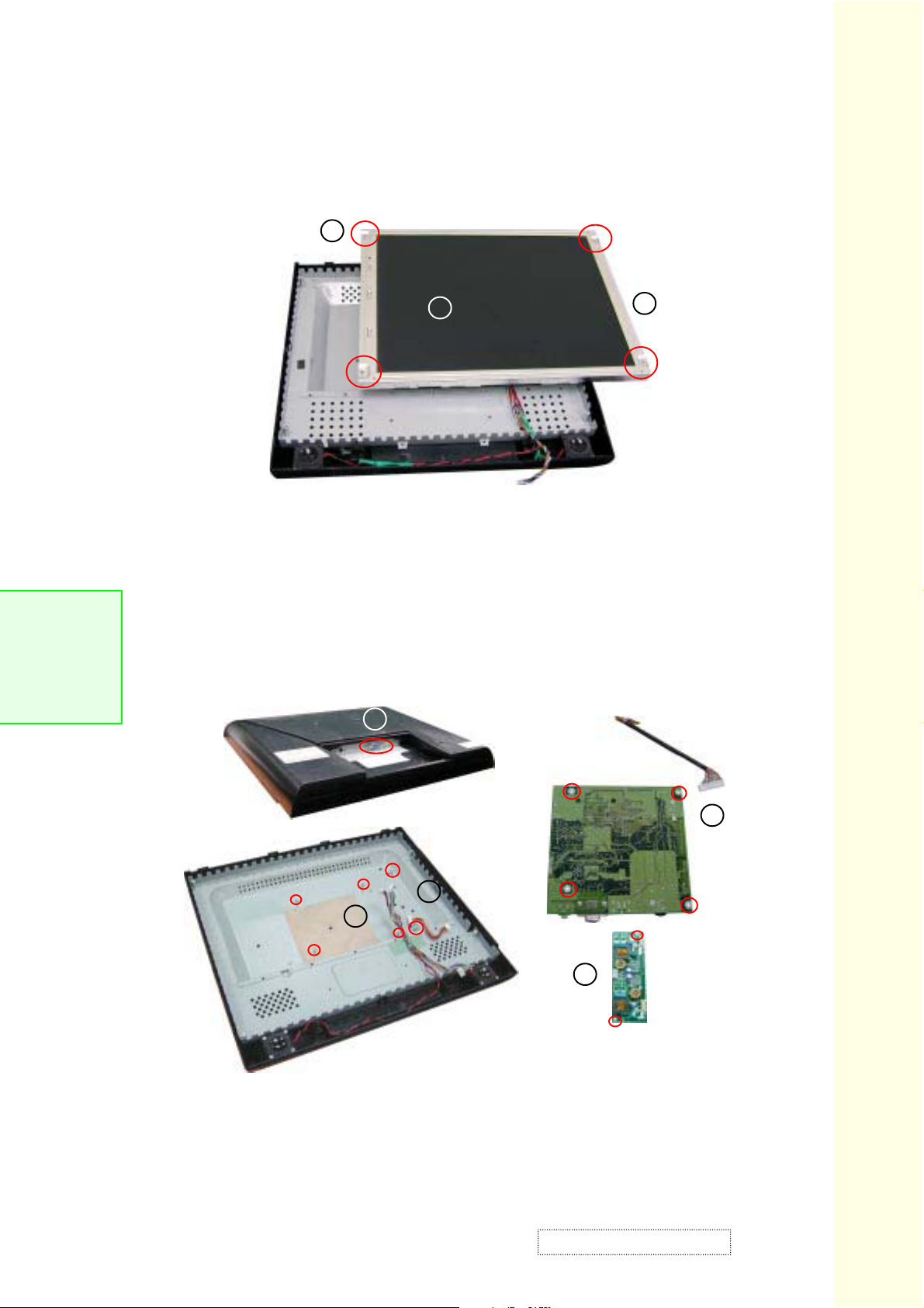
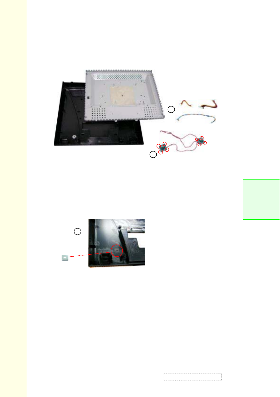
3-3 Disassembly of LCD Panel and Main Board
1
1. Unscrew the four screws on the LCD Panel.
VG700b series
2. Unplug all wires on the LCD Panel.
3. Remove the LCD Panel.
4
LCD Panel
3
2
VG700b Series Service Manual
4
Main Board
5
4
5
4. Unscrew the two hex screws and turn over the monitor first; then
unscrew the four screws and unplug all wires on Main Board to remove it.
5. Unscrew the two screws and unplug the wires of Inverter Board to remove it.
ViewSonic Corporation
Confidential – Do Not Copy
Inverter Board
3-3
VG700b
Page 17
3-4 Disassembly of Support Bracket, Speakers and all wires
Support Bracket
2
VG700b Series Service Manual
1
1. Unscrew the eight screws on Speakers to remove it.
2. Remove the tape, unscrew the four screws and unplug all wires
from Support Bracket.
3
Lock Bracket
Tinplate
Wires
Speakers
VG700b series
3-4
3. Remove the Lock Bracket Tinplate from Rear Cover.
ViewSonic Corporation
Confidential – Do Not Copy
VG700b
Page 18
Chapter 4 Function of Boards
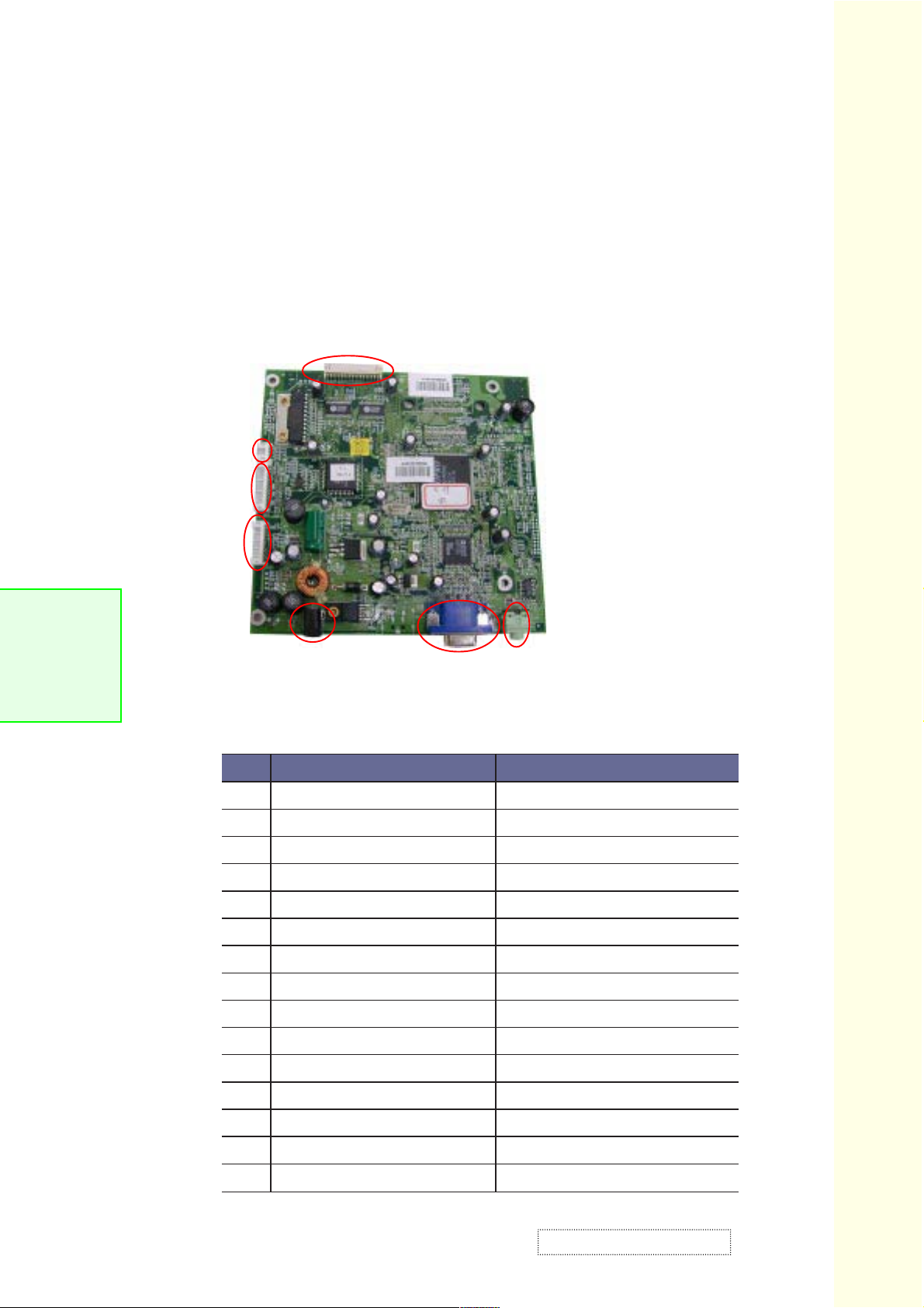
4-1 Main Board
4-1.1 The Location of Connectors
JP4
Con2
Con5
VG700b series
JP1
VG700b Series Service Manual
P1
Con1
4-1.2 CON1: VGA Connector
#niP noitpircseD noitcnuF
1DERtupnIoediVdeR
2NEERGtupnIoediVneerG
3EULBtupnIoediVeulB
4.C.NnoitcennoCoN
5DNG)ssapyBV5+(elbACevitceteD
6DNGdnuorGoediVdeR
7DNGdnuorGoediVneerG
8DNGdnuorGoediVeulB
9V5+TNOCV5+
01DNGdnuorG
11.C.NnoitcennoCoN
21ADSataDlaireS
J1
31SHCC.cnySlatnoziroH
41SVCC.cnySlacitreV
51LCS
ViewSonic Corporation
kcolClaireS
Confidential – Do Not Copy
4-1
VG700b
Page 19
4-1.3 CON2: OSD Key Connector
#niP noitpircseD noitcnuF
1
2
3
4
5
6
VG700b Series Service Manual
7
8
9
01
11
21
DNGdnuorG
rewoP
DNGdnuorG
1R_rewoP
1G_rewoP
llamS
pU
nwoD
GIB
tceleS
tiuQ
etuM
4-1.4 CON5: Inverter Connector
#niP noitpircseD noitcnuF
1
vnI_V21+
yeKrewoP
deRDELrewoP
neerGDELrewoP
-emuloV
esaercnI
esaerceD
+emuloV
tceleS
tiuQ
etuMemuloV
VG700b series
V21+
2
3
4
5
6
7
8
9
01
DNGdnuorG
KCABPFffO/nO
0DVDlortnoCssenthgirB
DNGdnuorG
vnI_V21+V21+
DNGdnuorG
KCABPFffO/nO
0DVDlortnoCssenthgirB
DNGdnuorG
4-1.5 J1: Phonejack Stereo Sw.Connector
#niP noitpircseD noitcnuF
1
2
3
4
5DNGdnuorG
NILtupnIlennahCtfeL
DNGdnuorG
DNGdnuorG
NIRtupnIlennahCthgiR
4-2
ViewSonic Corporation
Confidential – Do Not Copy
VG700b
Page 20
4-1.6 JP1 Connector
#niP noitpircseD noitcnuF
1DDVV3.3+rewoPSDVL
2DDVV3.3+rewoPSDVL
3DDVV3.3+rewoPSDVL
VG700b series
4
5SDVLLESnoitcennoCoN
6tnocVnoitcennoCoN
7DNGdnuorG
8+3NIOXRtupnIlaitnereffiDevitisoP
9-3NIOXRtupnIlaitnereffiDevitageN
01+NIKLCOXR+kcolCDDOlenaP
11-NIKLCOXR-kcolCDDOlenaP
21+2NIOXRtupnIlaitnereffiDevitisoP
31-2NIOXRtupnIlaitnereffiDevitageN
41DNGdnuorG
51+1NIOXRtupnIlaitnereffiDevitisoP
61-1NIOXRtupnIlaitnereffiDevitageN
71DNGdnuorG
81+0NIOXRtupnIlaitnereffiDevitisoP
91-0NIOXRtupnIlaitnereffiDevitageN
02+3NIEXRtupnIlaitnereffiDevitisoP
DNGdnuorG
VG700b Series Service Manual
12-3NIEXRtupnIlaitnereffiDevitageN
22+NIKLCEXR+kcolCnevElenaP
32-NIKLCEXR-kcolCnevElenaP
42DNGdnuorG
52+2NIEXRtupnIlaitnereffiDevitisoP
62-2NIEXRtupnIlaitnereffiDevitageN
72+1NIEXRtupnIlaitnereffiDevitisoP
82-1NIEXRtupnIlaitnereffiDevitageN
92+0NIEXRtupnIlaitnereffiDevitisoP
03-0NIEXRtupnIlaitnereffiDevitageN
ViewSonic Corporation
Confidential – Do Not Copy
4-3
VG700b
Page 21

4-1.8 JP4: Speaker Out Connector
#niP noitpircseD noitcnuF
1
2
3
4
3BFtuptuOlennahCthgiR
4BFtuptuOlennahCthgiR
5BFtuptuOlennahCtfeL
6BFtuptuOlennahCtfeL
VG700b Series Service Manual
4-2 Control Board
4-2.1 The Location of Connectors
VG700b series
CON2
4-2.2 CON2: OSD Key Connector
#niP noitpircseD noitcnuF
1DNGdnuorG
2rewoPyeKrewoP
3DNGdnuorG
41R_rewoPdeRDELrewoP
51G_rewoPneerGDELrewoP
6llamS-emuloV
7pUesaercnI
8nwoDesaerceD
9GIB+emuloV
01tceleStceleS
11tiuQtiuQ
21etuMetuMemuloV
4-4
ViewSonic Corporation
Confidential – Do Not Copy
VG700b
Page 22

4-3 Inverter Board
4-3.1 The Location of Connectors
4-3.2 CN1 Connector
VG700b series
CN3
CN2
CN1
#niP noitpircseD noitcnuF
1V21+ylppuSrewoPV21+
2V21+ylppuSrewoPV21+
3ffO/nOffO/nO
4ssenthgirBlortnoCthgirB
5DNGdnuorG
6DNGdnuorG
VG700b Series Service Manual
4-3.3 CN2 Connector
#niP noitpircseD noitcnuF
1)Vk1~(VCAtuptuOpmaL
2)Vk1~(VCAtuptuOpmaL
3.C.NnoitcennoCoN
4DNGdnuorG
4-3.4 CN3 Connector
#niP noitpircseD noitcnuF
1)Vk1~(VCAtuptuOpmaL
2)Vk1~(VCAtuptuOpmaL
3.C.NnoitcennoCoN
4DNGdnuorG
ViewSonic Corporation
Confidential – Do Not Copy
4-5
VG700b
Page 23

Chapter 5 Troubleshooting Procedure
5-1 Equipment Needed
Ɣ
VG700b Monitor
Ɣ
PC (Personal Computer) with 1280*1024resolution
Screw Driver
Ɣ
5-2 Main Procedure
VX700b series
Power-on
Power LED ok ?
Is display
performance ok ?
Start
Yes
No
No
VG700b Series Service Manual
A. Power Circuit
Troubleshooting
B. Performance
Troubleshooting
Are Speakers all right?
ViewSonic Corporation
Yes
Is function
adjustment ok ?
Yes
Yes
End
No
No
C. Function
Troubleshooting
D. Speakers
Troubleshooting
Confidential – Do Not Copy
5-1
VG700b
Page 24

5-2.1 A. Power Circuit Troubleshooting
Start
Change
AC/DC
Adapter
VG700b Series Service Manual
Yes
End
No
Change
Main Board
Yes
5-2.2 B. Performance Troubleshooting
Start
Change
Is screen black ?
Yes
Inverter Board
No
Change
Main Board
No
VX700b series
Change
LCD Panel
5-2
No
Is screen white ?
No
Abnormal Color ?
No
End
ViewSonic Corporation
Yes
Yes
Yes
Change
FPC Cable
Yes
Change
Main Board
Yes
No
No
Yes
Change
Main Board
Yes
Change
LCD Panel
Yes
Confidential – Do Not Copy
No
Yes
Change
LCD Panel
Yes
VG700b
Page 25

1
Is screen scrolling ?
Is screen flickering ?
VX700b series
Is LCD line defective?
Bad Uniformity ?
No
No
No
Yes
Yes
Yes
Yes
Change
VGA C abl e
Yes
Change
Main Board
Yes
Change
LCD Panel
Yes
Change
Inverter Board
No
No
Adjust H.size
Fine tune or
Auto Image
Adjust
Yes
Change
Main Board
Yes
Change
LCD Panel
Yes
Yes
Change
LCD Panel
No
VG700b Series Service Manual
Change
Main Board
Yes
No
Have line bar or noise?
No
Ghost image ?
No
End
Yes
Yes
Yes
Adjust H.size
Fine tune or
Auto Image Adjust
Yes
Connect VGA
cable to the PC
directly
Yes
No
Change
Main Board
Check the
No
Compatibility on
the computer
Feedback info.
to View Sonic
Yes
Yes
No
Yes
ViewSonic Corporation
Confidential – Do Not Copy
5-3
VG700b
Page 26

5-2.3 C. Function Troubleshooting
Start
Change Control
Board and Retry
VG700b Series Service Manual
Yes
End
No
Change
Main Board
and Retry
5-2.4 D. Speakers Troubleshooting
Start
Yes
VX700b series
5-4
ViewSonic Corporation
Change
Speakers
and Retry
Yes
End
No
Change
Main Board
and Retry
Yes
Confidential – Do Not Copy
VG700b
Page 27

Chapter 6 Function Test
& Alignment Procedure
6-1 Product and Test Equipment:
Ɣ
17 LCD monitor
Ɣ
Color Video Signal & Pattern (or PC with SXGA resolution)
6-2 Hot Key (Service Function):
, and Power on buttons with signal input: All Mode Reset
Ɣ
VG700b series
, and Power on buttons without signal input: Burn In Mode
Ɣ
Audio- and Audio+ buttons will recall volume to 50% while in volume
Ɣ
Adjustment, or when OSD is not open.
1 and buttons for 10 seconds: OSD locked
Ɣ
Do again: OSD unlocked.
1 and buttons for 10 seconds: Power button locked.
Ɣ
Do again: Power button unlocked.
VG700b Series Service Manual
Ɣ
1 and buttons and power buttons: White Balance
6-3 Test Condition:
Before function test and alignment, each LCD monitor should be run-in and
Ɣ
warmed-up for at least 2 hours with the following conditions:
a.) In Room Temperature,
b.) With full-white screen, R.G.B. Black
c.) With cycled display modes,
ViewSonic Corporation
Confidential – Do Not Copy
6-1
VG700b
Page 28

Ɣ
640*480 (H=31.5kHz, V=60Hz) 800*600 (H=37.9kHz, V=60Hz)
Ɣ
800*600 (H=46.9kHz, V=75Hz) 1024*768 (H=48.4kHz, V=60Hz)
Ɣ
Ɣ
Ɣ
1024*768 (H=56.5kHz, V=70Hz) 1024*768 (H=60kHz, V=75Hz)
Ɣ
1280*1024 (H=64kHz, V=60Hz) 1280*1024 (H=80kHz, V=75Hz)
Ɣ
Ɣ
6-4 Test Display Modes & Pattern
6-4.1 Compatible Modes
VG700b Series Service Manual
Resolution V. Frequency (Hz) H. Frequency (kHz) Standard
640*480 60 31.5 VESA VGA
640*480 67 35.0 MAC
640*480 72 37.9 VESA VGA
640*480 75 37.5 VESA VGA
720*400 70 31.5 VESA VGA
800*600 56 35.2 VESA SVGA
VG700b series
800*600 60 37.9 VESA SVGA
800*600 72 48.1 VESA SVGA
800*600 75 46.9 VESA SVGA
832*624 75 49.7 MAC
1024*768 75 60.2 MAC
1024*768 60 48.4 VESA XGA
1024*768 70 56.5 VESA XGA
1024*768 75 60.0 VESA XGA
1280*1024 60 64.0 VESA SXGA
1280*1024 75 80.0 VESA SXGA
6-2
ViewSonic Corporation
Confidential – Do Not Copy
VG700b
Page 29

6-4.2 Function Test Display Pattern
metI tnetnoCtseT nrettaP noitacificepS krameR
1
2ssenthgirB/tsartnoCelacSyarG61.elbahsiugnitsidebdluohsslevelyarg61 2erugiF
&ycneuqerF
gnikcarT
erioMeniLeniF.esionyvawlausivetanimilE 1erugiF
VG700b series
3yradnuoB
4
5
6eniL/lexiPdaeD
&latnoziroH
ssenkcihTlacitreV
roloC,B,G,R
ecnamrofreP
ytimrofinUneercS
rekcilF&
roloCB.G.R
seitisnetnI
etihWlluF.cepsehthtiwtnailpmocebdluohS 7erugiF
neercSetihW
neercSkraD
.emarf
.lamron
.cepsehthtiwtnailpmoc
dluohsoedivfonoitisop.treVdna.ziroH
neercsehtnihtiwebotelbatsujdaeb
ebdluohsroloc,B,G,RhcaefotsartnoC
3erugiF
erugiF
6,5,4
VG700b Series Service Manual
ebdluohsslexipdaedfosrebmunehT
8erugiF
Fine Line Morie Pattern (Figure 1) Gray Scale Pattern (Figure 2)
Horizontal & Vertical Thickness Pattern (Figure 3) R. Color Pattern (Figure 4)
ViewSonic Corporation
Confidential – Do Not Copy
VG700b
6-3
Page 30

VG700b Series Service Manual
G. Color Pattern (Figure 5) B. Color Pattern (Figure 6)
Full White Pattern (Figure 7) Dark Screen Pattern (Figure 8)
VG700b series
6-4
ViewSonic Corporation
Confidential – Do Not Copy
VG700b
Page 31

6-5 Function Test and Alignment Procedure
6-5.1 All Mode Reset
Input signal to VG700b, turn off the power of VG700b. Press ,
and Power on buttons on the select knob simultaneously for 3-5
seconds, release Power on button first, then else buttons. The screen
will show All Mode Reset. This action will allow you to erase all
end-users settings and restore the factory defaults.
6-5.2 Auto Image Adjust
Please select and enter Auto Image Adjust function on OSD
Main Menu or press 2 button directly. The Auto Image Adjust
function is aimed to offer a better screen quality by built-in ASIC. For
VG700b Series Service Manual
VG700b series
6-5.3 Fine Tune
6-5.4 Boundary
optimum screen quality, the user has to adjust each function manually.
Test Signal: 1280*1024@75Hz
Test Pattern: Line Moire Pattern
* Check and see if the image has noise and focus is well performed.
* If not, readjust by the following steps:
a.) Select and enter Manual Image Adjust function on OSD Main Menu.
b.) Then, select and enter Fine Tune function to adjust the image to
eliminate visual noise.
Test Signal: 1280*1024@75Hz
Test Pattern: Horizontal & Vertical Line Thickness Pattern
* Check and see if the image boundary is within the screen frame.
* If not, readjust by the following steps:
a.) Select and enter Manual Image Adjust function on OSD Main Menu.
b.) Then, select and enter Horizontal/Vertical Position or
ViewSonic Corporation
Scaling\Fit All function to adjust the video Boundary to be full
scanned and within screen frame.
Confidential – Do Not Copy
VG700b
6-5
Page 32

6-5.5 R.G.B. Colors Contrast
Test Signal: 1280*1024@75Hz
Test Pattern: R.G.B. Colors Intensities Pattern and 16 gray scale pattern
* Check and see if each color is normal and distinguishable
* If not, please return the unit to repair area
6-5.6 Screen Uniformity and Flicker
VG700b Series Service Manual
Test Signal: 1280*1024@75Hz
Test Pattern: Full White Pattern
* Check and see if it is in normal condition.
6-5.7 Dead Pixel and Line
Test Signal: 1280*1024@75Hz
Test Pattern: Dark Screen Pattern
* Check and see if there are dead pixels on LCD panel with shadow
gauge and filter film
* The total numbers and distance of dead pixels should be compliant
with the spec.
6-5.8 Check for Secondary Display Modes
Test Signal: 640*350@70Hz 640*480@60/67/72Hz;
720*400@70Hz 800*600@56/60/72/75Hz;
VG700b series
6-6
Normally when the primary mode 1280*1024@60Hz is well adjusted and
compliant with the specification, the secondary display modes will also
be compliant with spec. It is still necessary to check them with the
general test pattern to verify compliance though.
6-5.9 All Mode Reset
After final QC step, we have to erase all saved changes again and
restore the factory defaults. You should do All Mode Reset again. (ref. 6-5.1)
ViewSonic Corporation
832*624@75Hz 1024*768@60/70/72/75Hz;
1152*870@75Hz 1280*1024@60/70/75Hz
Confidential – Do Not Copy
VG700b
Page 33

6-6 Cleaning
Please use non-alcohol cleanser to clean LCD panel and cosmetics
material with soft cotton.
6-7 Inspection Standard
Appearance Inspection: Scratches/Abrasions
Ɣ
a.) Mechanical:
Face A: Not Allowed
VG700b series
VG700b Series Service Manual
Figure 1: Face A View
Face B: Length:12.7mm, Width: 0.25mm (2 lines,scrapes)
Figure 2: Face B View
ViewSonic Corporation
Confidential – Do Not Copy
6-7
VG700b
Page 34

Face C: Length:76mm Width:0.76mm (2 lines,scrapes)
VG700b Series Service Manual
Figure 3: Face C View
VG700b series
Face D: Length:89mm Width:0.76mm (2 lines,scrapes)
Figure4: Face D View
6-8
ViewSonic Corporation
Confidential – Do Not Copy
VG700b
Page 35

Chapter 7 Firmware Upgrade Procedure
Notice: 1.)Check FW version, it should be upgraded to latest version if it is old.
2.)Every time after Firmware upgrade, need to do DDC Keyin Procedure.
Electronically the VG700b is compatible with VG700. Please follow the
3.)
procedures shown in chapter 7 and 8 to upgrade the firmware and EDID
data.
7-1 Equipment Needed
Ɣ
VG700b monitor
Ɣ
Fixture for Firmware Upgrade
Ɣ
VGA Cable (P/N: 42.59901.004)* 2pcs
Ɣ
PC (Personal Computer)
Ɣ
Firmware Upgrade Program
Ɣ
Power Adapter (P/N: 47.58301.001)
Ɣ
Printer Cable
VG700b Series Service Manual
VG700b series
Print Port:
to Printer cable
VG700B
CON 2: VGA Out
CON3:
Print
Port
CON 1: VGA In
VGA Cable (P/N : 42.59901.004)
Printer Cable
ViewSonic Corporation
PC
Power Adapter (P/N: 47.58301.001)
Confidential – Do Not Copy
VG700b
7-1
Page 36

7-2 Hardware Setup Procedure
1. Connect Con1 of Fixture to VGA Port of PC.
2. Connect Con2 of Fixture to VGA Port on VG700b monitor.
3. Connect Con 3 of Fixture to Print Port of PC.
VG700b Series Service Manual
VG700b series
7-3 Firmware Upgrade Procedure
1. Save Firmware upgrade program in Computer:
7-2
ViewSonic Corporation
Confidential – Do Not Copy
VG700b
Page 37

2. Get into DOS mode.
VG700b series
VG700b Series Service Manual
3. Get into Firmware upgrade program where you save.
ViewSonic Corporation
Confidential – Do Not Copy
7-3
VG700b
Page 38

4. Firmware Programming
Notice:1.) The screen will become no video, but the power LED will twinkle. When the power
LED stops, it means program complete. You have no way to wake up screen, you
should unplug power cord, and replug it. Press Power the screen will wake up.
2.) Or you can use data transfer switch switch to another monitor when firmware
programming. You will see the program rate of progress below the screen when
the program rate of progress until 100%, it means firmware upgrade procedure
is completed.
3.) Get intoBurn In Mode(Ref.6-2), press any buttons besides Power button to
VG700b Series Service Manual
check the firmware version if it is correct.
VG700b series
7-4
5. Unplug Power Cord and plug it again.
6. After finish Firmware upgrade, you should do All Mode Reset.
(Ref.6-2),
7. Check Firmware version.
ViewSonic Corporation
Confidential – Do Not Copy
VG700b
Page 39

Chapter 8 EDID Update Procedure
8-1 Equipment Needed
Notice: Upgrade your monitor with DDC when Main board is replaced
Ɣ
VG700b monitor
Ɣ
Fixture for DDC Keyin
Ɣ
VGA Cable (P/N: 42.59901.004)* 2pcs
PC (Personal Computer)
Ɣ
Ɣ
DDC Keyin Program
Power Adapter (P/N: 47.58301.001)
Ɣ
Printer Cable
Ɣ
VG700b
VG700b series
CON 2: VGA Out
VG700b Series Service Manual
CON3:
Print
Port
Print Port:
to Printer cable
CON 1: VGA In
VGA Cable (P/N : 42.59901.004)
PC
Power Adapter (P/N: 47.58301.001)
Printer Cable
ViewSonic Corporation
Confidential – Do Not Copy
8-1
VG700b
Page 40

8-2 Hardware Setup Procedure
1. Connect Con1 of Fixture to VGA Port of PC.
2. Connect Con2 of Fixture to VGA Port on VG700b monitor.
3. Connect Con 3 of Fixture to Print Port of PC.
VG700b Series Service Manual
VG700b series
8-3 DDC Keyin Procedure
1. Save DDC Keyin Program in Computer:
8-2
ViewSonic Corporation
Confidential – Do Not Copy
VG700b
Page 41

2. Get into DOS mode.
VG700b series
VG700b Series Service Manual
3. Get into DDC Keyin program where you save.
ViewSonic Corporation
Confidential – Do Not Copy
8-3
VG700b
Page 42

4. Key in VG700V1 after DDC EDID Data Source file
(740DDC.DAT)=?
VG700b Series Service Manual
VG700b series
5. Key in S/N (Serial Number) or use bar code reader scanning, then
press Enter to begin programming.
8-4
ViewSonic Corporation
Confidential – Do Not Copy
VG700b
Page 43

6. The successful picture is as the following:
VG700b series
VG700b Series Service Manual
7. Press 1 on the select knob. then choose information to check
if S/N is correct. Get into Burn In Mode (Ref.6-2), press any button
besides Power button to double check if the S/N is correct.
ViewSonic Corporation
Confidential – Do Not Copy
8-5
VG700b
Page 44

Chapter 9 Panel Specification
9-1 LCD Panel (Model#:M170EN04)
A. Mechanical Specifications
Display Resolution 1280*1024
Dimensions 383.5(W)*306.5(H)*20.0(D)mm(Typ.)
Active Area 337.92*270.34mm
Pixel Pitch 0.264*0.264mm
Aspect Ratio 5:4
VG700b series
Mass Typical 2,000g
B. Optical Performance
Contrast Ratio
Luminance of White (Center)
White Uniformity >85% Min. (5 points measurement)
40:1 (max),
5
8
2 0 cd/m
2
(max),
400:1(typ),
250 cd/m
250:1(min)
2
(typ),
2
0
0 cd/
m
2
(min)
VG700b Series Service Manual
Viewing Angle H, V (CR>10) H:1
Response time (ms) Typical Tr=25ms; Tf=15ms,
Number of Backlight 4 CCFL
Backlight Life 50,000 hours (Typ.)/ 30,000 hours (Min.)
ViewSonic Corporation
o
40
, V=140
o
Maximum Tr=35ms; Tf=25ms
Confidential – Do Not Copy
9-1
VG700b
Page 45

Chapter 10 Packing for Shipping
10-1 Package
1. Take the ESD Bag to put on the Monitor, then fold the surplus ESD bag
and paste the tape.
VG700b series
VG700b Series Service Manual
Paste the tape on it.
2. Put the Cushions on the monitor. (Figure 3)
Left Cushion
Right Cushion
ViewSonic Corporation
Confidential – Do Not Copy
10-1
VG700b
Page 46

3.Take carton to put the monitor into the Carton and paste the tape
on the bottom of carton.
VG700b Series Service Manual
Paste the tape
on the bottom
4. Pay attention to the direction the monitor should face, when inserting it
into the carton, to ensure adequate protection during shipment.
Rear of Monitor
Front of Monitor
VG700b series
10-2
ViewSonic Corporation
Confidential – Do Not Copy
VG700b
Page 47

5. Warranty card for China area:
label
barcode
VG700b series
(a) Paste the label barcode on the right side of two columns of
model name and model number.
VG700b Series Service Manual
(b) Put Warranty sticker into Users guide set, attention the direction.
(c) Put Warranty card into Users guide set, attention the direction.
(d) Paste the Shipping warranty sticker on the Carton,
Notice: TCO99 mark must be coverd.
Warranty card
shipping warranty sticker
Shipping Warranty sticker
ViewSonic Corporation
Confidential – Do Not Copy
10-3
VG700b
Page 48

6.Warranty card for Japan area:
(a) Put Warranty sticker into Users guide set, attention the direction.
(b) Paste the label barcode on the warranty card.
(c)Put the Warranty card into the envelope and then put this
envelope into the shipping bag.
(d) Paste the Shipping bag on the Carton. (paste it on the other side)
VG700b Series Service Manual
Warranty sticker
Shipping Bag
Envelope
label barcode
VG700b series
Warranty card
Envelope
label barcode
Warranty card
Shipping Bag
Notice:
Warranty card
cant be put on
10-4
Paste it on the Carton label
ViewSonic Corporation
the View Sonic
logo.
View Sonic logo
Confidential – Do Not Copy
VG700b
Page 49

7. Put the accessories into Carton.(1)Power cord (2)VGA cable
Power cord
VGA cable
Audio cable
VG700b series
(3)Audio cable (4)Power adapter and then put User guide into Carton.
Rear side of user manual
Power
adapter
VG700b Series Service Manual
Paste the
transparent
adhesive tape
on the Carton
ViewSonic Corporation
Confidential – Do Not Copy
10-5
VG700b
Page 50

Chapter 11 Appendix
11-1 The Serial Number System Definition
11-1.1 Serial Number for LCD Display
PPP YY WW AAAAA
11
1
11
22
2
22
33
33
3
44
4
44
VG700b Series Service Manual
1
2
VG700b series
3
4
EX: A1R021200003
series model. Its produced on 12-week of 2002 and its serial code is 00003.
: PPP: Regional product ID code (ex:
: YY: Last 2 digits of manufacturing year (ex: 200
: WW: Manufacturing week
: AAAAA: Sequence number
This label A1R021200003 represents whole serial number for VG700b
A1R:VG700b.... series)
1 - 1, 2002 - 2)
ViewSonic Corporation
Confidential – Do Not Copy
11-1
VG700b
Page 51

11-1.2 Serial Number for PCBA Main Board
M VV B Y X G1 EEEE
1 2 3 4
5
6 7
VG700b Series Service Manual
: M = Vendor (ex: M= Might,)
1
: VV = Model Code (ex: I7= VG700b series...etc.)
2
: B = Main Board (ex: M= Main Board)
3
: Y = Last Number of the Year (ex: 2001 - 1, 2002 - 2)
4
: X = Month (ex: Jan.~Sept.=1 ~ 9, Oct.~Dec.=X, Y, Z)
5
: G1 = Version (ex: G1.....etc.)
6
7
: EEEE = Serial Code (from 0001~)
VG700b series
11-2
EX: MI7M29G10003
This label MI7M23G10003 represents Main board of version G1
for VG700b on Sept., 2002. Its serial code is 0003.
ViewSonic Corporation
Confidential – Do Not Copy
VG700b
Page 52

5
4
3
2
1
VG700 Model
+5V
R108
0
+5VE
D D
2
MPU_SCL
MPU_SDA
1
D2
BAV99
3
G
GREEN
G84A
R4
10K
C15
100P
2
1
D1
BAV99
3
R
C C
RED
MPU_SCL3
MPU_SDA3
0.1U
C28
2
3
0.01u
MPU_SCL
MPU_SDA
R5
10K
C16
100P
R109
0
1
C29
D3
BAV99
B
G84A
G84A
C23
0.1U
G84A
BLUE
C31
0.1U
C8
0.1U
C24
0.01u
*
If no need Snyc On
Green then open
C27
R12 100
R13 100
+3.3V_AD
G84A
C22 0.047U
C25 0.047U
C27 1000P
C30 0.047U
C32 0.1U
L_AP1
0805/600
C21 0.1U
CNC1
CNC2
CNC3
CNC4
ADA1
ADA2
G84A
C35
0.1U
G84A
+3.3V_AP
+3.3V_AD
+3.3V_AD
0.082U
41
42
44
45
46
47
48
49
50
51
52
53
54
55
56
57
59
60
+3.3V_AD
C36
0.01u
C3
G84A
AGND
VD
BAIN
AGND
VD
VD
AGND
GAIN
SONGIN
AGND
VD
AGND
RAIN
A0
SCL
SDA
Ref Bypass
VD
AGND
G84A
AA2
40
AGND
AGND
61
R3 2.7K
G84P
C11
0.1U
393738
VD
AGND
VD
63
62
C38
0.1U
0.0082U
AA3
C4
0.1U
C12
0.1U
363534
PVD
PGND
CLAMP
MIDSCV
AD9883
VSOUTVDGND
SOGOUT
DATACK
HSOUT
64
655867
66
C1
C5
1000P
PVD
68
33
FILT
PGND
VDD
Red.7
69
70
DV7
AAVS
AAHS
*
AD9883 pin29
connect to ground
C6
0.1U
282227
30
293231
AGND1
HSYNC
COAST
VSYNC
Red.2
Red.3
Red.4
Red.5
Red.6
DV5
DV3
DV6
DV4
DV2
DV1
R1 33
R2 33
C7
1000P
C10
0.1U
26
25
VD1
VD1
AGND1
Red.0
Red.1
77767574737271
DV0
C37
0.1U
24
AGND2
VDD
78
C209
22P
VDD
79
G84D
G84D
G84D
VDD
Green.0
Green.1
Green.2
Green.3
Green.4
Green.5
Green.6
Green.7
GND
80
C33
0.01u
HS
+3.3V_AD
C9
0.01u
214323
VDD
GND
GND
Blue.0
Blue.1
Blue.2
Blue.3
Blue.4
Blue.5
Blue.6
Blue.7
VDD
GND
GND
+3.3V_VD
+3.3V_VD
C2
+
100U
G84D +5V
U1A
VS24
VS
HS
HS24
+3.3V_VD
C26
0.1U
12
74F14
U1B
34
74F14
U1D
98
74F14
U1F
1312
74F14
VCC+5V
CTVS
CTHS
G84D
CONT+5V+5VIVCIVC
C203
22P
14+5V
C204
22P
R7 33
R8 33
R113
D6
1
2
BAV99
2.2K
CONT+5V
VGA Analog Input
U21
IC16
9
10
11
12
13
14
15
16
CON1
15
10
14
9
13
8
12
7
6
16
17
DB15HD Female
VGA In
8
7
6
5
4
3
2
1
5
4
3
2
111
SDA_A
SDA
SCL_A
SCL
SCL
SCL4
CCVS
CCHS
SDA
SDA4
R114
2.2K
!
IVC
3
C196
0.1uf
C17
22P
R6
10K
B
G
R
C18
22P
G84A
R106
0
R107
0
L2 0805/007
L3 0805/007
L4 0805/007
C19
22P
SDA_A
SCL_A
+5V
CABLE 3
BLUE
GREEN
RED
R9 75
R10 75
R11 75
D10
1 2
1N4148
C20
0.1U
TTVS
U1C
56
74F14
U1E
1110
74F14
TTHS
U2
AD9883
20
19
18
17
16
15
14
13
12
11
10
9
8
7
6
5
4
3
2
1
C210
22P
+3.3V_VD
+3.3V
DV16
DV17
DV18
DV19
DV20
DV21
DV22
DV23
DV8
DV9
DV10
DV11
DV12
DV13
DV14
DV15
VS
L1
0805/600
G84D
VSOUT4
B B
+5V
L6
5VIN1
0805/600
+5V
L8
A A
0805/600
+
100U
C39
5VIN2
+
0.1U
C43
100U
C40
C45
0.1U
4
U3
OUT
ADJ
LT1117
SOT_223
4
IN
U4
LT1117
SOT_223
3
2
1
IN
OUT
ADJ
+3.3VOUT1
G84A
+3.3OUT2
3
2
1
G84P
0805/600
L7
L9
AD9883 PLL
0805/600
SOGOUT4
EXVCLK4
+3.3V_AD
C41
+
100U
+3.3V_AP
C44
+
100U
R14 33
R16 33
R112 33
C193
G84D
12-1
5
AVSOUT
R18 68
47P
4
AVSOG
AEXVCK
G84D
C42
0.1U
+3.3V_VD
RP1
1 8
DV0
2 7
DV1
3 6
DV2
4 5
DV3
100X4
RP4
1 8
DV4
2 7
DV5
3 6
DV6
4 5
DV7
100X4
Confidential – Do Not Copy
3
AR0
AR1
AR2
AR3
AR4
AR5
AR6
AR7
AR[7..0] 4
DV8
DV9
DV10
DV11
DV12
DV13
DV14
DV15
RP2
1 8
2 7
3 6
4 5
100X4
RP5
1 8
2 7
3 6
4 5
100X4
AG0
AG1
AG2
AG3
AG4
AG5
AG6
AG7
AG[7..0] 4
DV16
DV17
DV18
DV19
DV20
DV21
DV22
DV23
2
RP3
1 8
2 7
3 6
4 5
100X4
RP6
1 8
2 7
3 6
4 5
100X4
AB0
AB1
AB2
AB3
AB4
AB5
AB6
AB7
AB[7..0] 4
TP1
L37
FB_G
Title
Size Document Number Rev
C
Date: Sheet
ViewSonic Corporation
Input / AD9883
1
Screw Pad
TP2
1
Screw Pad
VG700 H
1
TP4
L38
Screw Pad
FB_G
TP3
L40
Screw Pad
FB_G
16Wednesday, June 05, 2002
M04-3005F1 Rev .A
1
1
of
Page 53

5
4
3
2
1
VH
FPBACK
D D
Hight Voltage Switch
VL
+12V
AC 110-240V
Switch Power
AC Voltage
transform DC 12V
+12V
Switch Power
DC 12V to DC 5V
+5V
+3.3V
+3.3V
Oscillator
14.318MHz
RED DATA
RED DATA
GREEN DATA
BLUE DATA
CTRL/H/V/CLOCK
78.75MHz
D_sub 15 Pin
R/G/B
H/V Signal
A/D convert
AD9883-110
RGB Input
C C
TOPRO TPXXXX
Scaler
GREEN DATA
BLUE DATA
65MHz
LVDS
Transform
CTRL/H/V SINGAL
TX0-/TX1-/TX2-
TX0+/TX1+/TX2+
TCL-/TCL+
TFT LCD
ADT 17 Inch Panel
SERIAL SCL
SERIAL SDA
8 BIT DATA
CTRL SIGNAL
SDA
SCL
CLOCK 14.318MHZ
B B
MCU
Process
W78B62P
TXD
RXD
24C16
PROM
LED
CTRL SIGNAL
Ketpad
Control
DVD1 CTRL
Amplifier
R 16
ohm
AN7522
L 16
ohm
A A
ViewSonic Corporation
12-2
Title
Size Document Number Rev
Date: Sheet
5
4
3
2
Confidential – Do Not Copy
B
DIAGRAM
VG700 H
11Wednesday, June 05, 2002
of
M04-3005F1 Rev.A
1
Page 54

5
4
3
2
1
B1RED[7..4] 4
B1RED7
B1RED6
B1RED5
B1RED4
D D
B1RED[3..0] 4
B1RED3
B1RED2
B1RED1
B1RED0
B1GRN[7..4] 4
B1GRN7
B1GRN6
B1GRN5
B1GRN4
C C
B1GRN[3..0] 4
B1GRN3
B1GRN2
B1GRN1
B1GRN0
B1BLU[7..4] 4
B1BLU7
B1BLU6
B1BLU5
B1BLU[3..0] 4
B1BLU4
B1BLU3
B1BLU2
B1BLU1
B1BLU0
B B
LP1
1 8
2 7
3 6
4 5
100X4
LP3
1 8
2 7
3 6
4 5
100X4
LP5
1 8
2 7
3 6
4 5
100X4
LP7
1 8
2 7
3 6
4 5
100X4
LP9
1 8
2 7
3 6
4 5
100X4
LP11
1 8
2 7
3 6
4 5
100X4
1 8
2 7
GNDP
1 8
2 7
GNDP
1 8
2 7
GNDP
1 8
2 7
GNDP
1 8
2 7
GNDP
1 8
2 7
B2RED7
B2RED6
B2RED5
B2RED4
CP1
47pX4
3 6
4 5
B2RED3
B2RED2
B2RED1
B2RED0
CP3
47pX4
3 6
4 5
B2GRN7
B2GRN6
B2GRN5
B2GRN4
CP5
47pX4
3 6
4 5
B2GRN3
B2GRN2
B2GRN1
B2GRN0
CP7
47pX4
3 6
4 5
B2BLU7
B2BLU6
B2BLU5
B2BLU4
CP9
47pX4
3 6
4 5
B2BLU3
B2BLU2
B2BLU1
B2BLU0
CP11
47pX4
3 6
4 5
A1RED[3..0] 4
A1RED3
A1RED2
A1RED1
A1RED0
A1GRN[7..4] 4
A1GRN7
A1GRN6
A1GRN5
A1GRN4
A1GRN[3..0] 4
A1GRN3 A2GRN3
A1GRN2
A1GRN1
A1GRN0
A1BLU[7..4] 4
A1BLU7
1 8
A1BLU6
2 7
A1BLU5
3 6
A1BLU4
4 5
A1BLU[3..0] 4
A1BLU3
1 8
A1BLU2
2 7
A1BLU1
3 6
A1BLU0
4 5
B1RED[0..7]4
B1GRN[0..7]4
B1BLU[0..7]4
A1RED[0..7]4
A1GRN[0..7]4
A1BLU[0..7]4
LP2
1 8
2 7
3 6
4 5
100X4
LP4
1 8
2 7
3 6
4 5
100X4
LP6
1 8
2 7
3 6
4 5
100X4
LP8
100X4
LP10
100X4
1 8
GNDP
1 8
GNDP
1 8
2 7
GNDP
1 8
2 7
GNDP
1 8
2 7
GNDP
A2GRN7
A2GRN6
A2GRN5
A2GRN4
2 7
3 6
4 5
A2GRN2
A2GRN1
A2GRN0
2 7
3 6
4 5
A2BLU7
A2BLU6
A2BLU5
A2BLU4
CP8
47pX4
3 6
4 5
A2BLU3
A2BLU2
A2BLU1
A2BLU0
CP10
47pX4
3 6
4 5
B1RED[0..7]
B1GRN[0..7]
B1BLU[0..7]
A1RED[0..7]
A1GRN[0..7]
A1BLU[0..7]
3 6
CP4
47pX4
CP6
47pX4
4 5
A2RED3
A2RED2
A2RED1
A2RED0
CP2
47pX4
+3.3VD3
GNDP
+3.3VD3
GNDP
+3.3VD3
GNDP
+3.3VD3
+3.3VD3
GNDP
+3.3VD3
GNDP
+3.3VD3
GNDP
+3.3VD3
C54
0.1uF
C55
0.1uF
R23 0
C65
0.1uF
C75
0.1uF
GNDP
C88
0.1uF
C89
0.1uF
R24 0
C101
0.1uF
C103
0.1uF
A2RED7
A2RED5
A2GRN0
A2GRN1
A2GRN2
A2GRN6
A2GRN7
A2GRN3
A2GRN4
A2GRN5
A2BLU0
A2BLU6
A2BLU7
A2BLU1
A2BLU2
A2BLU3
A2BLU4
A2BLU5
DHS
DVS
B2RED7
B2RED5
B2GRN0
B2GRN1
B2GRN2
B2GRN6
B2GRN7
B2GRN3
B2GRN4
B2GRN5
B2BLU0
B2BLU6
B2BLU7
B2BLU1
B2BLU2
B2BLU3
B2BLU4
B2BLU5
DHS
DVS
1
2
3
4
5
6
7
8
9
10
11
12
13
14
15
16
17
18
19
20
21
22
23
24
25
26
27
28
1
2
3
4
5
6
7
8
9
10
11
12
13
14
15
16
17
18
19
20
21
22
23
24
25
26
27
28
U16-A1
VCC
TxIN5
TxIN6
TxIN7
GND
TxIN8
TxIN9
TxIN10
VCC
TxIN11
TxIN12
TxIN13
GND
TxIN14
TxIN15
TxIN16
VCC
TxIN17
TxIN18
TxIN19
GND
TxIN20
TxIN21
TxIN22
TxIN23
VCC
TxIN24
TxIN25
DS90CF383
U17-B1
VCC
TxIN5
TxIN6
TxIN7
GND
TxIN8
TxIN9
TxIN10
VCC
TxIN11
TxIN12
TxIN13
GND
TxIN14
TxIN15
TxIN16
VCC
TxIN17
TxIN18
TxIN19
GND
TxIN20
TxIN21
TxIN22
TxIN23
VCC
TxIN24
TxIN25
DS90CF383
B2BLU0
B2BLU1
B2BLU2
B2BLU3
B2BLU4
B2BLU5
B2BLU6
B2BLU7
B2RED0
B2RED1
B2RED2
B2RED3
B2RED4
B2RED5
B2RED6
B2RED7
DHS
DVS
DCLK
DEN
RxECLKINRxECLKIN+
TxIN4
TxIN3
TxIN2
GND
TxIN1
TxIN0
TxIN27
LVDSGND
TxOUT0-
TxOUT0+
TxOUT1-
TxOUT1+
LVDSVCC
LVDSGND
TxOUT2-
TxOUT2+
TxCLKOUT-
TxCLKOUT+
TxOUT3-
TxOUT3+
LVDSGND
PLLGND
PLLVCC
PLLGND
/PWRDWN
TxCLKIN
TxIN26
GND
TxIN4
TxIN3
TxIN2
GND
TxIN1
TxIN0
TxIN27
LVDSGND
TxOUT0-
TxOUT0+
TxOUT1-
TxOUT1+
LVDSVCC
LVDSGND
TxOUT2-
TxOUT2+
TxCLKOUT-
TxCLKOUT+
TxOUT3-
TxOUT3+
LVDSGND
PLLGND
PLLVCC
PLLGND
/PWRDWN
TxCLKIN
TxIN26
GND
DHS
DVS
DCLK
DEN
B2BLU[0..7]
B2RED[0..7]
+3.3VD3
C76
100u
A2RED4
56
A2RED3
55
A2RED2
54
53
A2RED1
52
A2RED0
51
A2RED6
50
49
RxOIN0-
48
RxOIN0+
47
RxOIN1-
46
RxOIN1+
45
44
43
RxOIN2-
42
RxOIN2+
41
RxOCLKIN-
40
RxOCLKIN+
39
RxOIN3-
38
RxOIN3+
37
36
GNDP
35
34
C66 0.1uF
33
32
DCLK
31
DEN
30
29
GNDP
56
55
54
53
52
51
50
49
48
47
46
45
44
43
42
41
40
39
38
37
36
35
34
33
32
31
30
29
B2RED4
B2RED3
B2RED2
B2RED1
B2RED0
B2RED6
RxEIN0RxEIN0+
RxEIN1RxEIN1+
C91 0.1uF
RxEIN2RxEIN2+
RxECLKINRxECLKIN+
RxEIN3RxEIN3+
GNDP
C102 0.1uF
DCLK
DEN
GNDP
C56 0.1uF
LVDS_EN 3
GNDP
+3.3VD3
GNDP
+3.3VD3
GNDP
GNDP
R27 10K
A2RED0
A2RED1
A2RED2
A2RED3
A2RED4
A2RED5
A2RED6
A2RED7
A2BLU0
A2BLU1
A2BLU2
A2BLU3
A2BLU4
A2BLU5
A2BLU6
A2BLU7
GNDP
GNDP
+3.3VD3
+3.3VD3
LVDS_EN 3
+3.3VD3
RxEIN0RxEIN0+
RxEIN1RxEIN1+
RxEIN2RxEIN2+
RxECLKINRxECLKIN+
RxEIN3RxEIN3+
RxOIN0RxOIN0+
RxOIN1RxOIN1+
RxOIN2RxOIN2+
RxOCLKINRxOCLKIN+
RxOIN3RxOIN3+
Vcont
SELLVDS
VDDout
C90
100uF/16V
A2RED[0..7]
A2BLU[0..7]
GNDP
C78
+
0.1uF
GNDP
C92
+
0.1uF
L10
0805/600
GNDPGNDPGNDP
+3.3V
30
29
28
27
26
25
24
23
22
21
20
19
18
17
16
15
14
13
12
11
10
9
8
7
6
5
4
3
2
1
HEADER 30
R25
0
+3.3VD3
R21
10K
Vcont
R22
10K
GNDP
JP1
SELLVDSDEN
R26
0
GNDP
A1RED[7..4] 4
A A
A1RED7
A1RED6
A1RED5
A1RED4
LP12
1 8
2 7
3 6
4 5
100X4
12-3
GNDP
A2RED7
A2RED6
A2RED5
A2RED4
CP12
47pX4
1 8
2 7
3 6
4 5
GNDP
5
4
Confidential – Do Not Copy
B2GRN0
B2GRN1
B2GRN2
B2GRN3
B2GRN4
B2GRN5
B2GRN6
B2GRN7
B2GRN[0..7]
3
A2GRN0
A2GRN1
A2GRN2
A2GRN3
A2GRN4
A2GRN5
A2GRN6
A2GRN7
A2GRN[0..7]
Title
Size Document Number Rev
C
Date: Sheet
2
ViewSonic Corporation
LVDS/Output Interface
VG700 H
1
26Wednesday, June 05, 2002
of
M04-3005F1 Rev .A
Page 55

5
VCC
C129
0.1U
35
UCLK
+12V_INV
100U
+12V_INV
FPBACK 4
DVD0 4
21
20
10
14
15
16
17
2
3
4
5
6
7
8
9
1
12
UCLK4
10K
R37
CABLE1
VCC
+5V
10K
R35
VCC
R83
3K
VCC
C115
0.1U
C120
+
10U
R32
4.7K
0.1U
MPU_SCL 4
MPU_SDA 4
RESET
INT04
PWR_G
PWR_R
MPU_SCL
MPU_SDA
PWR_KEY
CABLE
U6,6
U6,7
U6,8
U6,9
C131
C132
+
R85
0603/600
R86 0603/600
R84
3K
D D
RESET2
D5
1N4148
U18
1 8
A0 VCC
2 7
A1 WP
3 6
A2 SCL
4 5
C C
GND SDA
24C16
1 2
CON5
10
HEADER 10-2.0
Inverter Connector
+5V
1
2
3
4
5
6
7
8
9
INVERTER
I/F
B B
VCC
U6
43
EA/VP
X1
X2
RESET
INT0
INT1
T0
T1
P1.0
P1.1
P1.2
P1.3
P1.4
P1.5
P1.6
P1.7
NC
NC
P0.0
P0.1
P0.2
P0.3
P0.4
P0.5
P0.6
P0.7
P2.0
P2.1
P2.2
P2.3
P2.4
P2.5
P2.6
P2.7
WR
PSEN
ALE/P
TXD
RXD
RD
NC
NC
42
41
40
39
38
37
36
24
25
26
27
28
29
30
31
19
18
32
33
13
11
23
34
80C51_PLCC
MPU
VCC
GND
22 44
MPU Interface
POWER JACK4+12V DC Input
CON6
202
0.1U
3
4
L21 Coil
L44
Coil 150U
P1
1 2
3
L42
Coil 150U
1 2
4
RD 4
WR 4
C125
100P
AD[0..7] 4
CON2
HEADER 12-2.0
ALE 4
OSD Key Connector
MUTE
12
QUIT
11
SELECT
10
BIG
9
8
UP
7
SMALL
6
PWR_G1
5
PWR_R1
4
GND
3
POWER
2
GND
1
AD0
AD1
AD2
AD3
AD4
AD5
AD6
AD7
LVDS_EN 2
GPIO2 DOWN
Fan
U6,28
U6,29
U6,30
U6,31
TXD
RXD
*
If use LM2596-5 then:
R47 open & R45 = 0
U9
LM2576
+12V
C133
+
100U
+12V DC Input
POWER JACK3
C134
0.1U
6
12V-to-5V TO-220 5-Pin
/LM2596
ON
FB
GND
OUT
IN
C116
100P
C118
C117
100P
100P
C122
100P
100P
FB9 0603/600
FB7 0603/600
C123
100P
CONT+5V
FLOAT
5
4
3
OUTDB
2
1
C119
+5V
C130
RP10KX4
0.1U
L19 150UH_C
D4
1N5822
3
VCC
483726
RP7
SMALL
UP
DOWN
BIG
SELECT
QUIT
MUTE
R38 510
R39 510FB8 0603/600
+12V +12VP
15
1 5
R88
1K
CON2_2
R41 1K
C124
100P
D7 1N4148
D8 1N4148
D9 1N4148
R45
3K
R47
1K
L45 0805
C198
0.1uF
RP9
RP10KX4
4 8
3 7
2 6
PWR_G
R87
1K
RP10
1 8
2 7
3 6
4 5
Bead600/M4
RP8
1 8
2 7
3 6
4 5
Bead600/M4
VCC
R40
10K
PWR_KEY
VCC +3.3V
L18
FB_L
C135
0.1U
+5V
C136
+
1000U
C197
0.1uF
+5V_IN
C126
+
100U
U6,29
U6,9
U6,8
U6,30
U6,7
U6,6
U6,31
C127
4
0.1U
*
If use LT1084-3.3 then:
R103open&R104=0
C137
+
100U
R49 10K
FPVCC4
+5V +12V
R94
0
CON3
1
2
3
4
HEADER 4
Audio Connector
NORMAL R103 200 OHM
U7
LT1084
+3.3V Regulator
TO-220
IN
OUT
ADJ
PANEL POWER
CONTROL
FPVCC 0 ON
1 OFF
Q1
FPP1
B
SOT
23
E
3904
GNDP
Switch Control
SOT_23
R95
0
3
2
1
C
MPU_SDAIN
MMPU_SCL
OUTTT1
GNDP
Q3904_C
MOS1-D
MOS1-G
2
C213
+
100U
MMPU_SCL
R30 0
ADD DVD1 to control Audio VR
R33 0
R34 1K
L16
FB
L17
FB
R103
200
R104
330
C212
0.1u
GNDP
1 8
2 7
3 6
4 5
IRF7204
+12V
+5V
C128
+
100U
+5V
+12VP
R48
100K
R50
100K
0.1U
U19
SD
SD
SD
GD
MPU_SDA
C121
0.1U
C214
0.1U
U13
If use LT1117-3.3 then:
R81 open & R82 = 0
If use LT1117 for +2.5 then:
R81 / R82 = 120 ohm
+5V
L34
0805/600
+
100U
+12VP
<+5V>
L22
1206/600
Q2
MOS1-G
G
SOT
D
23
S
NMOS2304
N
MOSN
Power MOSN
GNDP
SOT_23
NMos
R51
3.3K
C139
GNDP
MPU_SCL
R36
1K
C188
L43
MOS1-D
GNDP
DVD1 4
Power option:
L15 on for TP6732/40
U13 on
forTP6750/60
C189
4
0.1U
1812/600
L23
1206/600
C138
0.1U
C140
2.2U
GNDP
U13
OUT
ADJ
LT1117
SOT_223
+3.3V
L41
Coil 150u
1
**
3
IN
2
1
+3.3V
R81
240
R82
390
+
L15
0805/600
C190
100U
+3.3V_VP
C215
0.1U
PANEL VOLTAGE SELECT:
ADT15"-->3.3V
FUJITSU15"-->5V
ADT17"-->5V
LG18"-->12V
VDDout
C201
0.1u
GNDP
R93
FanVcc
47
Q4
B
SOT
C
23
E
3904
Switch Control
SOT_23
MOS4
Vfanout
2
Vfanout
RXD
TXD
CON4
1
2
3
4
HEADER4X1
Debug & OSD Key
Pitch 2.54mm
Title
Size Document Number Rev
C
Date: Sheet
ViewSonic Corporation
MPU/IO Interface and Power
VG700 H
1
36Wednesday, June 05, 2002
of
M04-3005F1 Rev .A
Fan power
select Oct 15
R92
Fan4
10K
A A
12-4
5
4
Confidential – Do Not Copy
3
GNDP
B
SOT
C
23
E
3904
Switch Control
SOT_23
Q3
Fan1
R91
10K
Fan2
Page 56

5
+3.3V_VP
+3.3V_VP
MPU_SDA3
D D
UCLK3
C C
B B
R102
10k
SCL_A1
SDA_A1
+3.3V
47P
R101
+3.3V_VP
+3.3V_VP
UCLK
C165
AD[0..7]3
SOGOUT1
10k
L24
L26
R54 0
L29
L31
R59
33
AR[7..0]1
AG[7..0]1
AB[7..0]1
R61 0
22P
22P
R62 0
R64 0
R65 0
R66
1M
14.318MHz
HS21
VSOUT1
VS21
C169
C170
CVDD
C141
C142
X1
X2
0.1U
AVDD3
C149
+
AVDD2
C157
+
AVDD1
C161
+
100U
EXVCLK1
X1
100U
100U
AHSYNC
AVSYNC
C143
0.1U
RESET
ALE
INT0
WR
RD
UCLKOUT
AD0
AD1
AD2
AD3
AD4
AD5
AD6
AD7
AR0
AR1
AR2
AR3
AR4
AR5
AR6
AR7
AG0
AG1
AG2
AG3
AG4
AG5
AG6
AG7
AB0
AB1
AB2
AB3
AB4
AB5
AB6
AB7
+
100U
GNDA2 GNDA2 GNDA2
GNDA1
RESET3
ALE3
INT03
WR3
RD3
Crystal
C150
0.1U
C158
0.1U
C163
0.1U
C144
0.1U
GNDA3GNDA3 GNDA3
GNDA1GNDA1
151
137
140
139
138
136
133
132
131
130
129
128
127
126
207
208
1
2
3
4
5
6
185
186
187
188
189
190
191
192
166
167
168
169
170
171
172
173
8
9
10
11
12
13
14
15
198
199
200
201
202
203
204
205
175
176
177
178
179
180
181
182
17
18
19
20
21
156
153
154
0.01u
0.01u
0.01u
RESET
ALE
INT
WR*
RD*
UCLK
AD0
AD1
AD2
AD3
AD4
AD5
AD6
AD7
AR0
AR1
AR2
AR3
AR4
AR5
AR6
AR7
AG0
AG1
AG2
AG3
AG4
AG5
AG6
AG7
AB0
AB1
AB2
AB3
AB4
AB5
AB6
AB7
BR0
BR1
BR2
BR3
BR4
BR5
BR6
BR7
BG0/Y0
BG1/Y1
BG2/Y2
BG3/Y3
BG4/Y4
BG5/Y5
BG6/Y6
BG7/Y7
BB0/UV0/VD0
BB1/UV1/VD1
BB2/UV2/VD2
BB3/UV3/VD3
BB4/UV4/VD4
BB5/UV5/VD5
BB6/UV6/VD6
BB7/UV7/VD7
CLAMP
AHSYNC
AVSYNC
SCL
SDA
EXVCLK
XTALI/OSC
XTALO
Chip Interface
C146
C145
0.1U
0.1U
C151
C159
C164
152
157
160164297134
184
183741618098116
AVDD1
AVDD2
AVDD3
CVDD1
CVDD2
CVDD3
CVDD4
CVDD5
AVSS1
AVSS2
AVSS3
CVSS1
CVSS2
CVSS3
CVSS4
CVSS5
155
158
159222389142
197
174
DVDD1
DVDD2
MVDD1
DVSS1
DVSS2
MVSS1
20632487191
MVDD2
MVSS2
C147
0.1U
PVDD1
PVDD2
PVSS1
PVSS2
GNDP
PVDD3
PVSS3
107
135
141
UVDD
UVSS
4
C154
0.1U
C148
0.1U
GNDP
UVDD
MCLK
0.1U
C152
0.1U
C160
0.1U
C162
CKE
WE*
GNDMGNDM
GNDP
CAS*
4544434647
DVDD
C153
0.1U
C155
0.1U
RAS*
L25
MVDD
PVDD
C156
+
100U
GNDP
+5V
L32 FB
MD0
MD1
MD2
MD3
403938373635343331302928272625
L27
MD4
195
DDE
MD5
+3.3V
C199
0.1U
193
194
196
DHSYNC
DVSYNC
VCLK/IDCLK
MD6
MD7
MD8
C208
+
100U
MD9
MD10
L28
L30
MD11
+3.3V
MD12
MD13
MD14
24
MD15
+5V
+3.3V
163
VHSYNC
162
VVSYNC
VHREF
161
VVREF
165
3
U10
MA0
MA1
MA2
MA3
MA4
MA5
MA6
MA7
MA8
MA9
MA10
MA11
P0
P1
P2
P3
P4
P5
P6
P7
P8
P9
P10
P11
P12
P13
P14
P15
VD0/P16
VD1/P17
P18
P19
P20
P21
P22
P23
VD2/P24
VD3/P25
P26
P27
P28
P29
P30
P31
VD4/P32
VD5/P33
P34
P35
P36
P37
P38
P39
VD6/P40
VD7/P41
P42
P43
P44
P45
P46
P47
SHFCLK
PVSYNC
PHSYNC
PDE
FPVCC
FPBACK
DVD0
DVD1
RA7
RA6
RA5
RA4
RA3
RA2
RA1
RA0
VLLC
164
TP6732/TP6740
2
R52
10K
FSADDR7
R53
10K
FSADDR6
R55
10K
FSADDR3
R56
10K
FSADDR2
R57
10K
FSADDR1
R58
10K
FSADDR0
FSADDR[0..13] 5
A1BLU0
A1BLU1
A1BLU2
A1BLU3
A1BLU4
A1BLU5
A1BLU6
A1BLU7
A1GRN0
A1GRN1
A1GRN2
A1GRN3
A1GRN4
A1GRN5
A1GRN6
A1GRN7
A1RED0
A1RED1
A1RED2
A1RED3
A1RED4
A1RED5
A1RED6
A1RED7
B1BLU0
B1BLU1
B1BLU2
B1BLU3
B1BLU4
B1BLU5
B1BLU6
B1BLU7
B1GRN0
B1GRN1
B1GRN2
B1GRN3
B1GRN4
B1GRN5
B1GRN6
B1GRN7
B1RED0
B1RED1
B1RED2
B1RED3
B1RED4
B1RED5
B1RED6
B1RED7
FSADDR0
FSADDR1
FSADDR2
FSADDR3
FSADDR4
FSADDR5
FSADDR6
FSADDR7
FSADDR8
FSADDR9
FSADDR10
FSADDR11
FPVCC 3
FPBACK 3
VIDEO7
VIDEO6
VIDEO5
VIDEO4
VIDEO3
VIDEO2
VIDEO1
VIDEO0
A1BLU[7..0] 2
A1GRN[7..0] 2
A1RED[7..0] 2
B1BLU[7..0] 2
B1GRN[7..0] 2
B1RED[7..0] 2
ODCLK 2
PVSYNC 2
PHSYNC 2
ODEN 2
C211
+
100U
DVD0 3
DVD1 3
MVCLK
VHSYNC
VCLK
R80 33
C194
33P
U20
74F74
1
/RD0
2
D0
3
CP0
4
/SD0
5
Q0
6
/Q0
7 8
GND /Q1
VHSYNC VHSY
+3.3V
VCLK
C173
C192
33P
0.1uF
R96 22
VVREF
VIDEO0
VIDEO2
VIDEO4
VIDEO5
Video Input For SAA7114
+5V
C195
0.1uF
14
VCC
13
/RD1
12
D1
11
CP1
10
/SD1
9
Q1
JP3
12
34
56
78
910
11 12
13 14
15 16
17 18
19 20
HEADER 10X2
60
59
58
57
56
55
54
53
52
51
50
49
63
64
65
66
67
68
69
70
72
73
74
75
76
77
78
79
81
82
83
84
85
86
87
88
99
100
101
102
103
104
105
106
108
109
110
111
112
113
114
115
117
118
119
120
121
122
123
124
90
92
93
94
96
95
62
125
150
149
148
147
146
145
144
143
VIDEO1
VIDEO3
VIDEO6
VIDEO7
VHSYNC
VVSYNC
1
R98 0
R97 0
VHSY
MPU_SDA 1MPU_SCL1
+5V
C174
0.1uF
GNDA1
GNDA2
A A
TSCL
MPU_SCL3
R70 0
GNDA3
12-5
5
R71
0
GNDM
GNDP
C191
47P
R79
33
4
FSCKE
FSCLK
5
5
FSWE
5
FSRAS
FSCAS
5
5
R67
R68
R78
R69
33
33
33
VVSYNC
VHSY
FSDATA3
FSDATA1
FSDATA0
FSDATA7
FSDATA11
FSDATA6
FSDATA8
FSDATA4
FSDATA5
FSDATA2
FSDATA13
FSDATA9
FSDATA14
FSDATA10
FSDATA15
FSDATA12
FSDATA[0..15] 5
MVCLK
33
VVREF
Title
Size Document Number Rev
Confidential – Do Not Copy
3
2
C
Date: Sheet
ViewSonic Corporation
Scaler:TP6732
VG700 H
1
46Wednesday, June 05, 2002
of
M04-3005F1 Rev .A
Page 57

5
4
+3.3V_MQ+3.3V_MC
3
2
1
C176
+3.3V
C175
0.1uF
D D
GNDM
C C
+3.3V_MQ
L35
+3.3V_MC
L36
0.1uF
GNDM GNDM
FSDATA[0..15]4
FSADDR[0..13]4
FSCLK4
FSCKE4
FSRAS4
FSCAS4
FSWE4
C177
0.1uF
C178
0.1uF
FSADDR0
FSADDR1
FSADDR2
FSADDR3
FSADDR4
FSADDR5
FSADDR6
FSADDR7
FSADDR8
FSADDR9
FSADDR10
FSADDR11
C179
0.1uF
21
22
23
24
27
28
29
30
31
32
20
19
35
34
18
17
16
15
14
36
C180
0.1uF
U12
A0
A1
A2
A3
A4
A5
A6
A7
A8
A9
A10
A11
CLK
CKE
/CS
/RAS
/CAS
/WE
LDQM
UDQM
C181
0.1uF
+3.3V_MC
25713
VCC
VCC
VSS
VSS
26 1
504104147
VCCQ
VCCQ
VSSQ
VSSQ
+3.3V_MQ
38
44
VCCQ
VCCQ
VSSQ
VSSQ
GNDMGNDM
DQ0
DQ1
DQ2
DQ3
DQ4
DQ5
DQ6
DQ7
DQ8
DQ9
DQ10
DQ11
DQ12
DQ13
DQ14
DQ15
NC
K4S161622
FSDATA0
2
FSDATA1
3
FSDATA2
5
FSDATA3
6
FSDATA4
8
FSDATA5
9
FSDATA6
11
FSDATA7
12
FSDATA8
39
FSDATA9
40
FSDATA10
42
FSDATA11
43
FSDATA12
45
FSDATA13
46
FSDATA14
48
FSDATA15
49
37
CON8
41 40
41 40
42
43
44
45
A2RED1
A2RED3
A2RED4
A2RED6
A2GRN1
A2GRN3
A2GRN4
A2GRN6
A2BLU1
A2BLU3
A2BLU4
A2BLU6
B2RED1
B2RED3
B2RED4
B2RED6
B2GRN1
B2GRN3
B2GRN4
B B
B2GRN6
B2BLU1
B2BLU3
B2BLU4
B2BLU6
DCLK
DEN
46
47
48
49
50
51
52
53
54
55
56
57
58
59
60
61
62
63
64
65
66
67
68
69
70
71
72
73
74
75
76
77
78
79
80
GNDP
LCD Panel Connector
39
42
39
38
43
38
37
37
44
36
36
45
35
46
34
47
33
48
32
49
31
50
30
51
29
52
28
53
27
54
26
55
25
56
24
57
23
58
22
59
21
60
20
61
19
62
18
63
17
64
16
65
15
66
14
67
13
68
12
69
11
70
10
71
9
72
8
73
7
74
6
75
5
76
4
77
3
78
2
79
1
80
A2RED0
35
A2RED2
34
A2RED5
33
A2RED7
32
A2GRN0
31
A2GRN2
30
A2GRN5
29
A2GRN7
28
A2BLU0
27
A2BLU2
26
A2BLU5
25
A2BLU7
24
B2RED0
23
B2RED2
22
B2RED5
21
B2RED7
20
B2GRN0
19
B2GRN2
18
B2GRN5
17
B2GRN7
16
B2BLU0
15
B2BLU2
14
B2BLU5
13
B2BLU7
12
11
DHS
10
9
DVS
8
7
6
5
4
3
2
1
GNDP
VDDout
PLV1
GNDP
R72
4.7K
R73
4.7K
GNDP
C182
+
100U
C152A1
0.1U
B2BLU0
B2BLU1
B2BLU2
B2BLU3
B2BLU4
B2BLU5
B2BLU6
B2BLU7
B2RED0
B2RED1
B2RED2
B2RED3
B2RED4
B2RED5
B2RED6
B2RED7
B2GRN0
B2GRN1
B2GRN2
B2GRN3
B2GRN4
B2GRN5
B2GRN6
B2GRN7
B2BLU[0..7] 2
B2RED[0..7] 2
B2GRN[0..7] 2
A2GRN0
A2GRN1
A2GRN2
A2GRN3
A2GRN4
A2GRN5
A2GRN6
A2GRN7
A2BLU0
A2BLU1
A2BLU2
A2BLU3
A2BLU4
A2BLU5
A2BLU6
A2BLU7
A2RED0
A2RED1
A2RED2
A2RED3
A2RED4
A2RED5
A2RED6
A2RED7
A2RED[0..7] 2
A2GRN[0..7] 2
A2BLU[0..7] 2
Ground Plane: GNDP
DVS
DVS
DHS
A A
R74 33
DHS
R76 33
C183
C184
47P
47P
GNDPGNDP GNDP
PVSYNC
PHSYNC
PVSYNC 4
PHSYNC 4
DCLK
12-6
5
4
DEN
R75 33
DCLK
R77 33
C186
47P
GNDP
C185
47P
ODEN
ODEN 4DEN
ODCLK
ODCLK 4
C187
47P
GNDP
Confidential – Do Not Copy
3
Title
Size Document Number Rev
C
Date: Sheet
2
ViewSonic Corporation
Video Memory & Connector
VG700 H
1
56Wednesday, June 05, 2002
of
M04-3005F1 Rev .A
Page 58

5
4
3
2
1
C216
D D
100uF
C205 0.1uF
R28
1K
DVD1
A1
12
11
10
9
8
7
C C
6
5
AAGND
C47 1.0uF
C46 1.0uF
4
3
2
1
R105
R19
CA2
R20
LIN
RIN
CA1
R15 10k
R17
FB3 0603
FB4 0603
FB5 0603
FB6 0603
JP4
1
2
3
4
4 HEADER
SPEAK OUT
AN7522
0
10K
0.01uF
L46
10K
COIL
0.01uF
100K
U6,28
U6,28
STANDBY
L11
B B
L12
1206
1206
+12V
+5V
C200
C48
470uF
J1
0.01uF
1
2
3
4
AAINL1
AAINR1
FB1
FB2
0603-600
0603-600
R110 36K
R111 36K
LIN
RIN
ViewSonic Corporation
5
A A
C206
C207
PHONEJACK STEREO SW
0.01uF
0.01uF
Title
AUDIO AMPLIFIER
Size Document Number Rev
A
VG700 H
12-7
Date: Sheet
Confidential – Do Not Copy
5
4
3
2
66Wednesday, June 05, 2002
of
M04-3005F1 Rev.A
1
Page 59

ViewSonic Corporation
Confidential – Do Not Copy
VG700b
13-1
VG700b
Page 60

ViewSonic Corporation
Confidential – Do Not Copy
VG700b
13-2
VG700b
Page 61

ViewSonic Corporation
Confidential – Do Not Copy
VG700b
13-3
VG700b
Page 62

14. VG700B RECOMMENDED PARTS LIST
K
Item CATEGORY PART NAME DESCRIPTION VIEWSONIC P/N REFERENCE
M-WR-0828-0657
M-WR-0828-0644
M-WR-0828-0636 42.58302.001
A-AU-0120-0032
A-PC-0106-0186
A-PC-0106-0189 42.58204.001
A-AD-0114-0149
M-MS-0808-8299 51.58711.002
P-BX-0601-0748
P-FM-0602-0752
P-FM-0602-0753
42.58203.011
42.58301.001
42.59903.001
42.50112.001
47.58301.001
55.58301.002
56.58301.002
56.58302.002
1 CABLES
2 ADAPTER
3LCD
4 SPEAKERS
CASE /COVER
5
/BRACKET
ASSEMBLY
MISCELLANEOUS6
7 BOARDS
8 PACKAGE
CONTROL WIRE W.A. 12P UL1571 #28 260mm (MB TO CTRL)
INVERTER WIRE W.A. 10/6P UL1007 #24 100mm VG700(INV)
INTERFACE WIRE
AUDIO CABLE CABLE AUDIO 1.8M LM/BK/LM VX2000
VGA CABLE CABLE VGA 15P 1800mm 2 CORE A-VC-0101-0265 42.59901.004
POWER CORD CABLE POWER CORD 1830mm SP-023+IS14 EUR.
POWER CORD CABLE POWER CORD 1830mm (JPN) BLACK A-PC-0106-0190 42.50116.002
POWER CORD CABLE POWER CORD 1.8M±0.1M (CHINA) A-PC-0106-0187 42.50126.001
POWER CORD CABLE POWER CORD 1.8M±0.1M UNSHIELD (NA) A-PC-0106-0188 42.57207.001
POWER CORD CABEL POWER CORD 1830mm PC TYPE COLOR:BLAC
ADAPTER ADAPTER IN:100-240V OUT:12V/3.33A;LSE
LCD PANEL
SPEAKER
FRONT COVER FRONT COVER ABS HB-VS08A;VG700b C-FP-0301-0901 51.58301.002
REAR COVER REAR COVER ABS HB-VS08A VG700b C-BC-0302-0442 51.58302.002
BASE COVER BASE COVER ABS HB-VS08;VG700b M-CV-0830-2343 51.58311.002
FRONT ARM FRONT ARM ABS HB-VS08;VG700b M-MS-0808-8300 51.58312.002
REAR ARM REAR ARM ABS HB-VS08;VG700b M-MS-0808-8302 51.58313.002
BASE PLATE BASE PLATE SGCC 2.0t VG700/750/700b M-MS-0808-8146 61.58303.001
COSMETIC CAP ASSY COSMETIC CAP CS-VS08 VG700b M-MS-0808-8298 75.58301.002
COSMETIC CAP COSMETIC CAP ABS HB-VS08 VG700b M-MS-0808-8297 51.58303.002
HINGE HINGE TILT SPHC 2.0t VG700/750/700b M-MS-0808-8145 61.58302.001
HINGE CAP HINGE CAP ABS HB-VS08;VG700b M-MS-0808-8301 51.58304.002
NAMEPLATE NAMEPLATE ELLIPSE ViewSonic
RUBBER FOOT RUBBER FOOT 25*10*1.2t PL-PD-0714-0064 52.00003.001
INVERTER BOARD PCBA INVERTER PLCD2417414 EMAX B-SB-0221-0447 44.58302.001
CONTROL BOARD
MAIN BOARD
LABEL LABEL CARTON 76*76mm M-LB-0813-0706 35.58203.001
MANUAL USER'S GUIDE MULTILINGUAL+CD, VG700b A-CD-VG750 36.58302.002
BAG EPE BAG 540*750*0.5t W/HOLE, VG700b M-MS-0808-8334 51.00081.005
CARTON CARTON AB VG700b
CUSHION CUSHION-R EPS VG700
CUSHION CUSHION-L EPS VG700
SMALL CUSHION EPE CUSHION, VG700b P-FM-0602-0799 56.58303.001
W.A. 30P UL20276 #28 200mm+CORE
TFT LCD 1280*1024 17" ADT L170E3 PANEL M-LCD-0826-0120 48.56902.001
ASSY SPEAKER 3W/16R 3mm EVA FILM/PU MATERIA E-SK-0412-0057 49.58502.002
PCBA CTRL BD B-CB-0206-0135 80.58202.001
PCBA MAIN BD VG700/700b B-MB-0201-0671 80.58301.001
ViewSonic Corporation
Confidential – Do Not Copy
14-1
VG700b
Page 63

Date: Sep-24-2002
Item: 95.58304.00V
Description: VG700b LCD DISPLAY;"VIEWSONIC", Midnight Gray, AU-M170EN04,WW UOM: SET
Item ViewSonic P/N Component Rev Description UOM Q'ty
eve
Seq Substitutes Location
1 10 DC.58302.001 A D.C. VG700b,AUO (MIDNIGHT GRAY) Pcs 1
.2 10 35.58303.002 A LABEL BRACKET 168*82.5mm VG700b Pcs 1
.2 20 M-LB-0813-0726 35.58302.001 A LABEL BAR CODE 40*40mm ViewSonic Pcs 1
.2 30 35.58304.001 A LABEL BARCODE 40*14 ViewSonic Pcs 1
.2 40 A-AD-0114-0149 47.58301.001 A ADAPTER IN:100-240V OUT:12V/3.33A;LSE Pcs 1
.2 50 51.00014.002 A FILAMENT TAPE 3M NO.8915 25mm*55M ROL 0.0045
.2 60 M-MS-0808-8301 51.58304.002 A HINGE CAP ABS HB-VS08;VG700b Pcs 1
.2 70 M-MS-0808-8302 51.58313.002 A REAR ARM ABS HB-VS08;VG700b Pcs 1
.2 80 M-MS-0808-8299 51.58711.002 A NAMEPLATE ELLIPSE CS-VS08 ViewSonic Pcs 1
.2 90 70.58306.001 A ASSY DISPLAY VG700b,AUO (MISNIGHT GRAY) Pcs 1
..3 10 35.00010.002 A LABEL CAUTION HIGH VOLTAGE 25.4*19mm Pcs 1
..3 20 M-LB-0830-0695 35.58202.001 A BIRD LOGO AL E015-001 ViewSonic Pcs 1
..3 30 M-LB-0813-0726 35.58303.001 A LABEL BRACKET 168*82.5mm VG700 Pcs 1
..3 40 35.90305.001 A ViewSonic AL-LOGO Pcs 1
..3 50 39.58302.002 A0 1 DDC RECORDER VG700b Pcs 1
..3 60 41.57708.001 A EMI TAPE(80773)35*40mm Pcs 1
..3 70 M-WR-0828-0657 42.58203.011 B W.A.12P UL1571#28 260mm W/CORE(MB/CTRL) Pcs 1
..3 80 M-WR-0828-0636 42.58301.001 A W.A. 10/6P UL1007 #24 100mm VG700(INV) Pcs 1
..3 90 M-WR-0828-0644 42.58302.001 A W.A. 30P UL20276 #28 200mm+CORE Pcs 1
..3 100 B-SB-0221-0447 44.58302.001 A PCBA INVERTER PLCD2417414 EMAX Pcs 1
..3 110 M-LCD-0826-0120 48.56902.001 A TFT LCD 1280*1024 17" ADT L170E3 PANEL Pcs 1
..3 120 E-SK-0412-0057 49.58501.002 A ASSY SPEAKER 3W/16R 3mm EVA FILM/PU MATERIA Pcs 1
..3 130 51.00028.001 A WIRE MOUNTS PG-FW-4D TFT450 Pcs 1
..3 140 C-FP-0301-0901 51.58301.002 A FRONT COVER ABS HB-VS08A;VG700b Pcs 1
..3 150 51.58305.001 A INSULATION MYLAR FOR VG700/750 Pcs 1
..3 160 51.58306.001 A LIGHT LEAKAGE 24*34*0.05mm MYLAR VG700/750 Pcs 2
..3 170 M-MS-0808-8239 51.59901.001 A ACETATE TAPE W=20mm CM 7.5
..3 180 52.00004.002 A RUBBER PAD CS-VS08 VG700b Pcs 4
..3 190 52.58301.001 A RUBBER FOOT 10*10*12mm(H) Pcs 1
..3 200 61.58301.001 A SUPPORT BRKT SECC 0.8t VG700(ADT) Pcs 1
..3 210 M-MS-0808-8298 75.58301.002 A ASSY COSMETIC CAP CS-VS08 VG700b Pcs 1
...4 10 51.58206.002 A SELECT KNOB ABS HB-VS08;VG500 Pcs 1
...4 20 M-MS-0808-8176 51.58207.001 A LED LENS ACRYLIC VG500 Pcs 1
...4 30 M-MS-0808-8297 51.58303.002 A COSMETIC CAP ABS HB-VS08 VG700b Pcs 1
..3 220 75.58302.002 A ASSY REAR COVER CS-VS08 VG700b Pcs 1
...4 10 C-BC-0302-0442 51.58302.002 A REAR COVER ABS HB-VS08A VG700b Pcs 1
...4 20 61.00042.001 A LOCK BRKT+CAP SECC 0.8t Pcs 1
..3 230 B-MB-0201-0671 80.58301.001 H5 PCBA MAIN BD VG700 Pcs 1
...4 10 00.57703.001 H BARE PCB L:4 MAIN BD PV755AV Pcs 1
...4 15 01.00034.501 A RES RP 0 5% 1/4W CHIP #1206 Pcs 3
...4 20 01.00036.502 A RES RP 0 5% 1/16W CHIP #0603;"TA-I TECHNOLO Pcs 12
...4 30 01.10136.501 A RES RP 100 5% 1/16W #0603 Pcs 4
...4 35 01.10136.502 A RES RP 100 5% 1/16W X4 V8V 8P SMD Pcs 18
...4 41 01.10236.502 A RES RP 1K 5% 1/16W #0603;"TA-I TECHNOLOGY" Pcs 3
...4 45 01.10316.501 A RES RP 10K 1% 1/16W CHIP #0603 Pcs 1
...4 50 01.10336.501 A RES RP 10K 5% 1/16W x4 V8V 8P SMD "PANASO Pcs 2
...4 60 01.10336.502 A RES RP 10K 5% 1/16W CHIP #0603;"TA-I TECHNO Pcs 13
...4 70 01.10436.501 A RES RP 100K 5% 1/16W CHIP #0603 Pcs 3
...4 81 01.10536.501 A RES RP 1M 5% 1/16W CHIP#0603 Pcs 1
...4 85 01.20116.501 A RES RP 200 1% 1/16W CHIP #0603 Pcs 1
COMPLETE PARTS LIST
L37, L38, L40.
R106,R107,R108,R109,R14,R16,R23,
R1, R12, R13. R2,
RP1, RP2, RP3, RP4, RP5,RP6,LP1, LP3, LP4, LP5,
LP6. LP7,LP11,LP12,LP2,LP8,LP9, LP10,
R41, R87, R88.
R3.
RP7. RP9,
R101,R102,R15, R27, R35,R37,R40, R49,R52,R58,
R6,R55,R56.
R17. R48, R50,
R66.
R103.
ViewSonic Corporation
Confidential – Do Not Copy
14-2
VG700b
Page 64

...4 87 01.20236.501 A RES RP 2K 5% 1/16W CHIP #0603;'TA-I TECHNOL Pcs 1
R33.
...4 90 01.22236.501 A RES RP 2.2K 5% 1/16W CHIP #0603 Pcs 4
R113,R114.R19, R20,
...4 95 01.30116.501 A RES RP 330 1% 1/16W CHIP #0603 Pcs 1
R104.
...4 100 01.30236.501 A RES RP 3K 5% 1/16W CHIP #0603 Pcs 4
R28, R34, R51, R84.
...4 110 01.33036.502 A RES RP 33 5% 1/16W CHIP #0603;"TA-I TECHNOL Pcs 6
R59, R7, R74, R75, R76,
...4 140 01.47236.501 A RES RP 4.7K 5% 1/16W CHIP #0603 Pcs 1
R32.
...4 150 01.51136.501 A RES RP 510 5% 1/16W CHIP #0603;"TA-I TECHNO Pcs 2
R38. R39,
...4 155 01.68036.501 A RES RP 68 5% 1/16W CHIP #0603 Pcs 2
R18, R77.
...4 160 01.75016.501 A RES RP 75 1% 1/16W CHIP #0603;"TA-I TECHNOL Pcs 3
R10, R11, R9.
...4 163 01.78216.501 A RES RP 7.87K 1% 1/16W CHIP #0603 Pcs 2
R110,R111.
...4 170 02.10074.404 A CAP CE 10u 20% 16V 4*7 RADIAL Pcs 1
C120.
...4 180 02.10174.404 A CAP CE 100u 20% 16V 6.3*11 RADIAL 105 degre Pcs 14
C126,C141,C156,C161,C182,C190C44. C48, C90,, C2,
C208,C216,C39,C41,
...4 195 02.10274.403 A CAP CE 1000u 16V 20% 10*20mm 105к (HD) LOW Pcs 1
C136.
...4 200 02.10547.102 A CAP CC 100pF 5% 50V NPO #0603 Pcs 8
C116,C117,C118,C119,C122, C123, C124, C125.
...4 210 02.10647.101 A CAP CC 1000pF 10% 50V X7R #0603 Pcs 1
C24.
...4 215 02.10747.101 A CAP CC 0.01uF 10% 50V X7R #0603;"YCTC""TEAM Pcs 12
C151,C159,C164,C206,C207C9,, C29,C33,
...4 220 02.10887.101 A CAP CC 0.1uF +80%-20% 50V Y5V #0603; "YCTC" Pcs 64
...4 240 02.22447.101 A CAP CC 22pF 5% 50V NPO #0603; "YCTC","TEAM Pcs 2
...4 291 02.47174.404 A CAP CE 470u 20% 16V 8*11.5 105 Degree RADIA Pcs 4
...4 293 02.47487.101 A CAP CC 47pF*4 NPO 8P4C #1206 Pcs 12
...4 295 02.47647.101 A CAP CC 47pF 5% 50V NPO #0603 Pcs 1
...4 300 02.47745.103 A CAP CC 0.047uF 10% 25V X7R #0603 Pcs 3
...4 302 02.56647.102 A CAP CC 0.0056uF 10% 50V X7R #0603 Pcs 1
...4 305 02.56745.101 A CAP CC 0.056uF 10% 25V X7R #0603 Pcs 1
...4 310 03.00020.401 A INDCTR BEAD 600ȍ CHIP #0805 "MAG LAYERS" Pcs 15
...4 315 03.00052.401 A INDCTOR BEAD MLB-160808-0600A-N1 SMD ; "MAG Pcs 12
...4 340 03.00122.401 A MLB3216-0600M4-N2 600ȍx4 at 100Mhz #1206 Pcs 2
...4 345 03.00127.401 A INDCTR BEAD #0805 100MHz 30R MLB201209-0030 Pcs 3
...4 348 03.00129.401 A INDCTR BEAD #1206 100MHz 300R MLB321611-030 Pcs 4
...4 350 03.15100.301 A INDCTR CHOKE 150uH 20% 3A DIP A0060D1 "ARON Pcs 1
C10, C102, C103, C11, C115,C135, C138, C139, C142,
C143, C152, C152A1, C153, C154, C155, C199, C20,
C200, C201, C202, C31, C32, C37, C38, C40, C6,
C65,C66, C75, C8,C12,C121, C127,C129,C131,C134,
C144, C145, C146, C147,C148,C150,C158,
C160,C162,C163, C197,C198, C205, C21, C212,C23,
C26, C28, C42, C46,
C169,C170.
C128,C132,C133,C137.
CP1, CP10,CP11,CP12.CP2,CP3,CP4,
CP9,CP5,CP6,CP7,CP8,
C165.
C22, C25, C30.
C1.
C3.
L1, L10. L15, L24, L25,L26,L27, L29,L30,L31,L32,L45,
L6, L7, L_AP1,
FB1, FB2, FB3, FB4, FB5,FB6,FB7, R86,
FB8,FB9,R105.R85,
RP10.RP8,
L2, L3, L4.
D7, D8, L18, L22.
ViewSonic Corporation
Confidential – Do Not Copy
14-3
VG700b
Page 65

L19.
...4 352 03.15142.301 A INDCR COIL 150uH 10% 1.4A 2 PIN RADIAL FERR Pcs 3
L41, L44, L46.
...4 355 03.22040.301 A INDCTR CHOKE COIL 22u 10% 3A DIP A00601C2 " Pcs 1
L42.
...4 360 07.14318.001 A XTAL 14.318MHz HC-49S HALF SIZE "ព" Pcs 1
X1.
...4 370 08.2N390.402 A TRNSTR NPN GENERAL MMBT3904LT1 SOT-23 "MO Pcs 1
Q1.
...4 380 09.1N582.201 A DIODE IN5822 SCHOTTKY RECTIFIER DO201AD Pcs 1
D4.
...4 391 09.1PS22.601 A DIODE HIGH-SPEED 1PS226 SMD "PHILIPS" Pcs 3
D1, D2, D3.
...4 398 09.SS054.001 A DIODE SCHOTTKY Barrier SS0540 0.5 A SOD123 Pcs 1
D10.
...4 401 11.010F2.305 A CNNT F PWR JACK PJ-20 "HCH" Pcs 1
P1.
...4 410 11.042M2.306 A CNNT M 4P 2mm RT/LEAD TU2001WNR-04 "TYU" Pcs 1
JP4.
...4 416 11.059F2.010 A CNNT PHONE JACK ST/LEAD 2SJ-P520-A04 LIME ( Pcs 1
J1.
...4 420 11.102M2.303 A CNNT 10P 2.0mm TU2001WNR-10 RT/DIP;"TYU" Pcs 1
CON5.
...4 430 11.122M2.303 A CNNT 12P 2.0mm TU2001WNR-12 RT/DIP;"TYU" Pcs 1
CON2.
...4 440 11.155F2.203 A CNNT D-SUB 15P RT/LEAD BLUE PC99 VGA Pcs 1
CON1.
...4 445 11.302M2.301 A CNNT M 30P 2mm RT/LEAD P220-2*15-R ;"LCU" Pcs 1
JP1.
...4 470 20.11173.301 A IC VOLTAGE REGULATOR LT1117-3.3 800mA SOT-2 Pcs 1
U3.
...4 490 20.74ACT.142 A IC CMOS MC74ACT14D HEX INVERTING 14SOIC ; " Pcs 1
U1.
...4 501 20.AD988.311 A IC AD9883-140 A/D CONVERTOR 140MSPS TQFP-80 Pcs 1
U2.
...4 510 20.AIC10.841 A IC AIC1084CM 5A LINEAR REG TO-263 Pcs 1
U7.
...4 520 20.AN752.201 A IC AUDIO AN7522 DUAL 3-W AMPLIFIER Pcs 1
A1.
...4 525 20.CS582.801 A IC LVDS CS5828 8BIT 56PIN TSSOP 85MHZ Pcs 2
U16-A1, U17-B1.
...4 530 20.SI230.4D1 A IC NMOS SI2304DS VISHAY SOT-23 Pcs 1
Q2.
...4 540 20.SI805.0S1 A IC SI-8050S(LF1102) Switching Regulator TO2 Pcs 1
U9.
...4 551 20.TP674.001 A IC ASIC TP6740 XGA TOPRO 208 PIN QFP SCANLI Pcs 1
U10.
...4 560 21.24LC1.601 A IC EEPROM 24LC16B/SN M 2K*8 BIT IIC BUS 8SO Pcs 1
U18.
...4 575 22.58301.001 A0 8 FW EPROM VG700 Pcs 1
....5 20 21.W78E6.2B1 A IC W78E62BP-40 MLU 4KB MTP 64KB ISP FL Pcs 1
U6.
....5 30 39.58301.001 A0 8 FW BIOS SOURCE CODE VG700 Pcs 1
...4 580 35.00017.001 A LABEL BIOS 13*11mm BLANK Pcs 1
U6.
...4 590 35.00018.001 A LABEL BARCODE 13*26.5mm BLANK Pcs 2
...4 595 61.00039.001 A EYELET BR ij3*4.0 Pcs 2
A1.
...4 600 61.00039.002 A EYELET BR ij3*6.0 Pcs 1
U9.
..3 240 B-CB-0206-0135 80.58202.001 B PCBA CTRL BD VG500 Pcs 1
...4 10 00.58201.001 B BARE PCB L:2 CTRL BD VG500 Pcs 1
...4 20 09.L115V.EG1 A DIODE LED GREEN/RED DIP D3.0mm L-115VEGW " Pcs 1
D1.
...4 30 11.122M2.302 A CNNT M 12P 2mm RT/LEAD P-220-2*6-R Pcs 1
CON2.
...4 35 35.00016.001 A LABEL BARCODE 6*38mm BLANK Pcs 1
...4 40 43.52102.002 A SWITCH PUSH PT-002-B2 DC12V 50mA Pcs 8
SW1, SW2, SW3, SW4, SW5,SW7, SW8.SW6,
ViewSonic Corporation
Confidential – Do Not Copy
14-4
VG700b
Page 66

..3 250 M-MS-0808-6287 85.005AG.075 A SCREW HEX I/O #4-40*H5*L7.5 Ni NYLOK Pcs 2
..3 260 M-SCW-0824-0651 85.1F123.060 A SCREW PAN MECH W/SF M3*6 Ni Pcs 6
..3 270 85.SA123.070 A SCREW BIN TAP/2L M3*7Ni Pcs 4
..3 280 85.SA123.120 A SCREW BIN TAP/2L M3*12 Ni Pcs 2
..3 290 M-SCW-0824-0655 85.UA323.070 A SCREW PAN TAP DOUBLE THREADS M3*7 Black Pcs 11
..3 300 M-SCW-0824-0688 85.ZA123.100 A SCREW WCH/W MECH M3*10 Ni Pcs 4
.2 100 70.58307.001 A ASSY STAND CS-VS08 VG700b Pcs 1
..3 10 M-CV-0830-2343 51.58311.002 A BASE COVER ABS HB-VS08;VG700b Pcs 1
..3 20 M-MS-0808-8300 51.58312.002 A FRONT ARM ABS HB-VS08;VG700b Pcs 1
..3 30 PL-PD-0714-0064 52.00003.001 A RUBBER FOOT 25*10*1.2t Pcs 5
..3 40 M-MS-0808-8145 61.58302.001 A HINGE TILT SPHC 2.0t VG700/750 Pcs 1
..3 50 M-MS-0808-8146 61.58303.001 A BASE PLATE SGCC 2.0t VG700/750 Pcs 1
..3 60 85.1F124.120 A SCREW PAN MECH W/SF M4*12 Ni Pcs 4
..3 70 85.4A124.060 A SCREW FLAT MECH M4*6 Ni Pcs 4
..3 80 85.SA123.070 A SCREW BIN TAP/2L M3*7Ni Pcs 4
..3 90 M-SCW-0824-0656 85.YA123.080 A SCREW FLAT TAP M3*8 Ni Pcs 4
1 20 DP.58302.00V A D.P. VG700b,WORLD WIDE Pcs 1
.2 10 A-PC-0106-0186 42.50112.001 A CABLE POWER CORD 1830mm SP-023+IS14 EUR. Pcs 1
.2 15 A-PC-0106-0188 42.57207.001 A CABLE POWER CORD 1.8M±0.1M UNSHIELD (NA) Pcs 1
.2 20 70.583DP.002 A COMMON PACKAGE VG700b Pcs 1
..3 10 M-LB-0813-0706 35.58203.001 A LABEL CARTON 76*76mm Pcs 1
..3 20 A-CD-VG750 36.58302.002 A USER'S GUIDE MULTILINGUAL+CD+TCO95 ECO DOCU Pcs 1
..3 30 A-VC-0101-0265 42.59901.004 A CABLE VGA 15P 1800mm 2 CORE Pcs 1
..3 40 A-AU-0120-0032 42.59903.001 A CABLE AUDIO 1.8M LM/BK/LM VX2000 Pcs 1
..3 50 51.00069.001 A PACKING STRAP 12MM*2000M*0.6MM ROL 0.023
..3 60 51.00070.001 A PE STRETCH FILM 500MM*1500M*0.02MM ROL 0.0003
..3 70 51.00080.001 A 3 INCH TRANSPARENT ADHESIVE TAPE (600M) ROL 0.002
..3 80 M-MS-0808-8334 51.00081.005 A EPE BAG 540*750*0.5t W/HOLE VG700b Pcs 1
..3 90 55.55103.001 A CORNER BOARD 50*50*5*1050mm Pcs 0.133
..3 100 55.56707.001 A CORNER BOARD 50*50*740mm Pcs 0.05
..3 110 55.57202.001 A CORNER BOARD 50*50*5*960mm Pcs 0.05
..3 120 55.57503.001 A CORNER BOARD 50*50*5*1700MM Pcs 1E-05
..3 130 P-BX-0601-0748 55.58301.002 A CARTON AB VG700b Pcs 1
..3 140 P-FM-0602-0752 56.58301.002 A CUSHIONS R EPS VG700 Pcs 1
..3 150 P-FM-0602-0753 56.58302.002 A CUSHIONS L EPS VG700 Pcs 1
..3 155 P-FM-0602-0799 56.58303.001 A EPE CUSHIONS VG700b Pcs 1
..3 160 58.58301.001 A WOOD PALLET 1125*1000mm Pcs 0.025
ViewSonic Corporation
Confidential – Do Not Copy
14-5
VG700b
 Loading...