

Page 1

Page 2

Contents
Product Registration................................................... 2
For Your Records....................................................... 2
Getting Started
Package Contents...................................................... 3
Precautions ................................................................ 3
Quick Installation........................................................ 4
Installation of Wall Mount (Optional) .......................... 5
Using the LCD Display
Setting the Timing Mode ............................................ 6
OSD and Power Button Lock Modes .........................6
Adjusting the Screen Image .......................................7
Main Menu Controls ...................................................9
Other Information
Specifications ...........................................................12
Troubleshooting .......................................................13
Customer Support ....................................................14
Cleaning the LCD Display ........................................15
Limited Warranty ......................................................16
Appendix
Safety Guidelines .....................................................17
Compliance Information for U.S.A............................ 18
CE Conformity for Europe ........................................18
01/02/03 C ViewSonic VG700/VG700b 1
Page 3

Copyright © ViewSonic Corporation, 2002. All rights reserved.
Macintosh and Power Macintosh are registered trademarks of Apple Computer, Inc.
Microsoft, Windows, Windows NT, and the Windows logo are registered trademarks of
Microsoft Corporation in the United States and other countries.
ViewSonic, the three birds logo, OnView, ViewMatch, and ViewMeter are registered trademarks of
ViewSonic Corporation.
VESA is a registered trademark of the Video Electronics Standards Association. DPMS and DDC
are trademarks of VESA.
®
E
NERGY STAR
is a registered trademark of the U.S. Environmental Protection Agency (EPA).
As an E
E
NERGY STAR
NERGY STAR
®
®
partner, ViewSonic Corporation has determined that this product meets the
guidelines for energy efficiency.
Disclaimer: ViewSonic Corporation shall not be liable for technical or editorial errors or omissions
contained herein; nor for incidental or consequential damages resulting from furnishing this
material, or the performance or use of this product.
In the interest of continuing product improvement, ViewSonic Corporation reserves the right to
change product specifications without notice. Information in this document may change without
notice.
No part of this document may be copied, reproduced, or transmitted by any means, for any purpose
without prior written permission from ViewSonic Corporation.
Product Registration
To meet your future needs, and to receive any additional product information as it becomes
available, please register your product on the Internet at:
www.viewsonic.com
Wizard CD-ROM also provides an opportunity for you to print the registration form, which you
may mail or fax to ViewSonic.
For Your Records
Product Name:
Model Number:
Document Number:
Serial Number:
Purchase Date:
ViewSonic VG700/VG700b
VLCDS23719-1W/3W
A-CD-VG700-1/A-CD-VG700b-1
______________
______________
. The ViewSonic
Product disposal at end of product life
ViewSonic is concerned about the preservation of our environment. Please dispose of this product
properly at the end of its useful life. Your local waste disposal company may provide information
about proper disposal.
ViewSonic VG700/VG700b 2
Page 4

Getting Started
Congratulations on your purchase of a ViewSonic® LCD display.
Important! Save the original box and all packing material for future shipping
needs.
NOTE: The word “Windows” refers to Microsoft Windows 95, 98, NT, XP,
2000 and Me (Millennium).
Package Contents
IMPORTANT: Save all packing material.
Your LCD display package includes:
• LCD display
• Power cords
• Audio cable
• Video cable (VGA)
• AC/DC Adapter
• ViewSonic Wizard CD-ROM
NOTE:
The CD jacket contains the Quick Start Guide, and the CD includes User
Guide PDF files and INF/ICM display optimization files. The INF files ensures
compatibility with Windows operating systems, and the ICM file (Image Color
Matching) ensures accurate on-screen colors. ViewSonic recommends that you
install both files.
Precautions
• Sit at least 18" from your LCD display
display.
Avoid touching the screen.
•
difficult to remove.
Never remove the rear cover.
•
display contains high-voltage parts. You may
be seriously injured if you touch them.
• Avoid exposing your LCD display to direct
sunlight or another heat source. Orient your
LCD display away from direct sunlight to
reduce glare.
• Always handle your LCD display with care
when moving it.
Skin oils are
Your LCD
• Place your LCD display in a well-ventilated
area. Do not place anything on your LCD
display that prevents heat dissipation.
• Ensure the area around the LCD display is
clean and free of moisture.
• Do not place heavy objects on the LCD
display, video cable, or power cord.
• If smoke, abnormal noise, or strange odor is
present, immediately switch the LCD display
off and call your dealer or ViewSonic. It is
dangerous to continue using the LCD display.
ViewSonic VG700/VG700b 3
Page 5
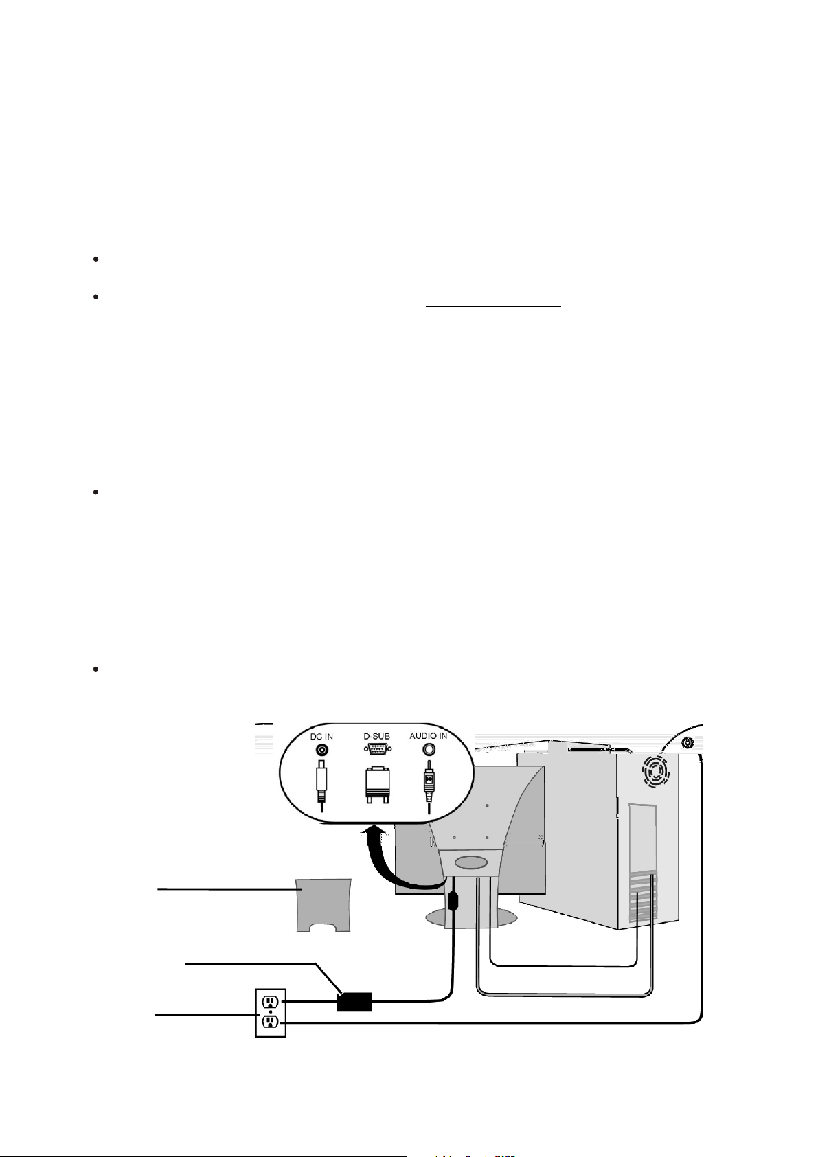
Quick Installation
Optional:
see page 5 of this user guide.
For instructions on wall mounting,
1 Connect power cord and AC/DC
adapter
2 Connect video cable
Make sure both the LCD
computer are turned OFF
Connect the video cable from the LCD
display to the computer
Macintosh users: Models older than G3
require a Macintosh adapter. Attach the
adapter to the computer and plug the video
cable into the adapter.
To order a ViewSonic
contact ViewSonic Customer Support.
display and
Macintosh adapter ,
3 Turn ON LCD display and
computer
Turn ON the LCD display, then turn ON
the computer. This sequence
(LCD display before computer) is
important.
NOTE:
receive a message asking them to install the
INF file. This is on the CD.
Windows 95, 98 or 2000 users may
4 Insert the ViewSonic Wizard CD
into the computer s CD drive
Follow the on-screen instructions
If your computer does not have a CD-ROM
drive, see Customer Support.
(1) Wait for the CD-ROM to auto-start.
NOTE:
double-click on the CD-ROM icon in the
Windows Explorer, then double-click on
viewsonic.exe
(2) Follow the on-screen instructions.
If the CD-ROM does not auto-start:
.
5 Windows users: Set the timing
mode (resolution and refresh
rate)
Example: 1280 X 1024 @ 60 Hz.
For instructions on changing the resolution
and refresh rate, see the graphic card s user
guide.
Installation is complete. Enjoy your new
ViewSonic LCD display.
To be best prepared for any future customer
service needs: print this user guide and write
the serial number in or Your Records on
page 2. (See back of LCD display.)
You can register your product online at the
website for your region. See the Customer
Support table in this guide.
The ViewSonic Wizard CD-ROM also
provides an opportunity for you to print the
registration form which you may mail or fax
to ViewSonic.
Back plate
AC/DC adapter
with power cord
AC outlet
(wall socket)
Audio cable
Video cable
Computer power cord
ViewSonic VG700/VG700b 4
Page 6
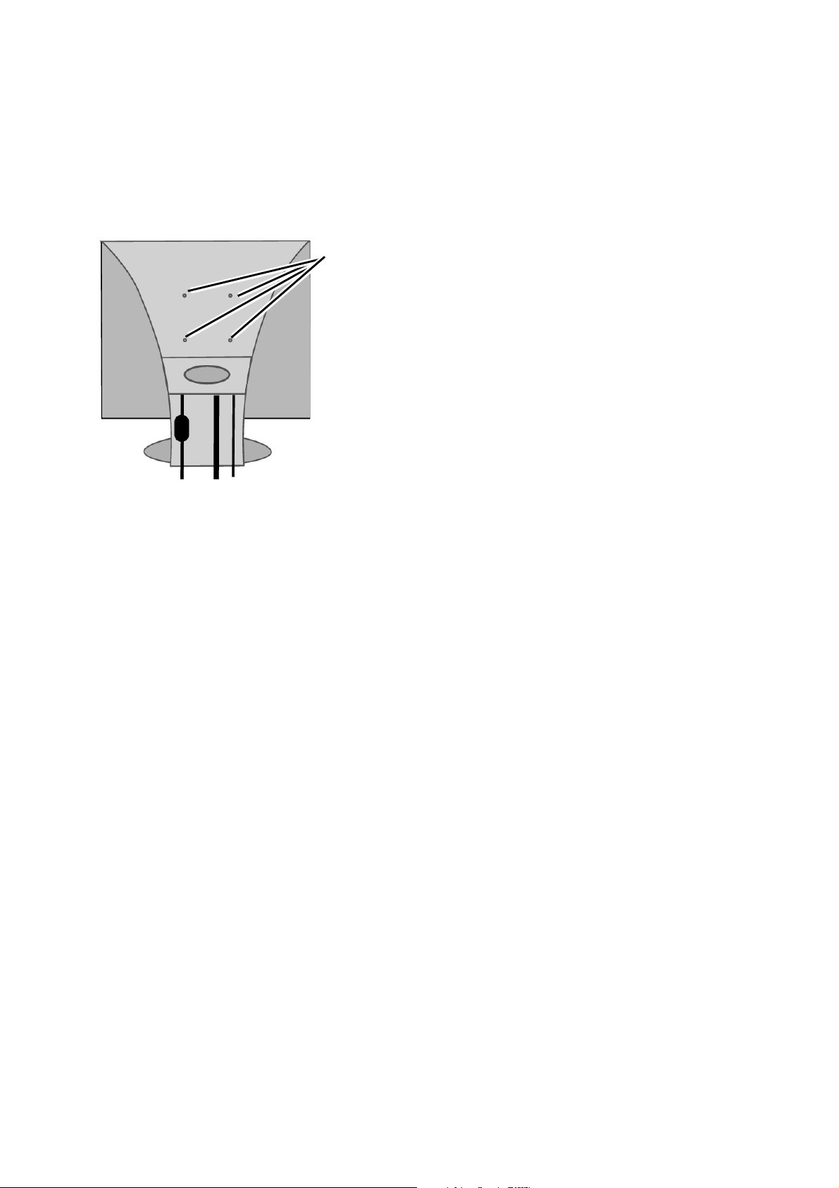
Installation of Wall Mount (Optional)
To obtain a wall-mounting kit, contact ViewSonic or your local dealer. Refer to
the instructions that come with the base mounting kit. To convert your LCD
display from a desk-mounted to a wall-mounted display, do the following:
1
Disconnect Power.
Four
screw
holes
2
Lay the LCD display face down
on a towel or blanket. Notice the
four screw holes on the bottom of
the base for the wall mount.
3
Attach the mounting bracket
from the VESA compatible wallmounting kit (100 mm x 100 mm
distance).
4
Attach the LCD display to the
wall, following the instructions in
the wall-mounting kit.
ViewSonic VG700/VG700b 5
Page 7

Using the LCD Display
Setting the Timing Mode
Setting the timing mode is important for maximizing the quality of the
screen image and minimizing eye strain. The timing mode consists of the
resolution (example 1280 x 1024) and refresh rate (or vertical frequency;
®
example 60 Hz). After setting the timing mode, use the OnView
to adjust the screen image.
For the best picture quality set your LCD displaytiming mode to:
VESA 1280 x 1024 @ 60 Hz.
To set the Timing Mode:
1
Set the resolution: Right-click on the Windows desktop > Properties >
Settings > set the resolution.
2
Set the refresh rate: See your graphic card's user guide for instructions.
controls
WARNING:
maximum refresh rate of 75 Hz; doing so may result in permanent damage to
your LCD display.
Do not set the graphics card in your computer to exceed the
OSD and Power Button Lock Modes
OSD Lock: This mode locks all current control settings and prevents access to
the control menus until this mode is unlocked.
I
• OSD Lock: Press and hold [1] and the up arrow
buttons are pressed the message OSD Locked will display for 5 seconds.
• OSD Unlock: Press and hold [1] and the up arrow
Power Button Lock: This mode locks the power of the LCD display in the ON
position.
• Power Button Lock: Press and hold [1] and the down arrow
seconds. If the power button is pressed the message Power Button Locked
will display for 5 seconds. With or without this setting, after a power failure,
your LCD display’s power will automatically turn ON when power is
restored.
for 10 seconds. If any
I
again for 10 seconds.
J for 10
• Power Button Unlock: Press and hold [1] and the down arrow
10 seconds.
ViewSonic VG700/VG700b 6
J again for
Page 8
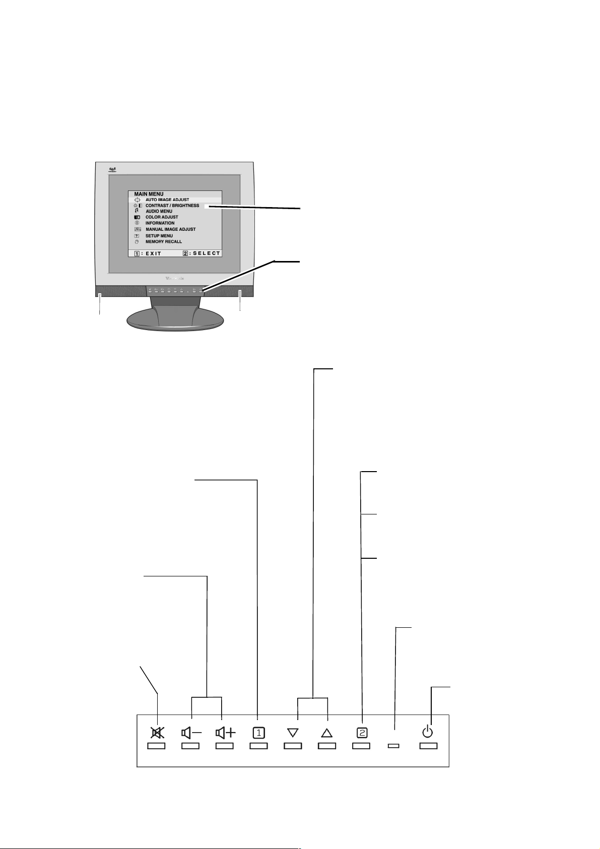
Adjusting the Screen Image
Use the buttons on the front control panel to display and adjust the OnView
®
controls which display on the screen. The OnView controls are explained at the
top of the next page and are defined in “Main Menu Controls” on page 9.
Main Menu
With OnView controls
Front Control Panel
shown below in detail
Speaker
Speaker
Scrolls through menu options and
adjusts the displayed control.
Displays the Main Menu
or exits the control screen
and saves adjustments.
Decreases or
increases volume.
Temporarily silences
audio output.
Also a shortcut to display the
Contrast adjustment control
screen.
Displays the control
screen for the highlighted
control.
Also toggles between two
controls on some
screens.
Also a shortcut to Auto
Image Adjust.
Power light
Green = ON
Orange = Power
Saving
Power
On/Off
ViewSonic VG700/VG700b 7
Page 9
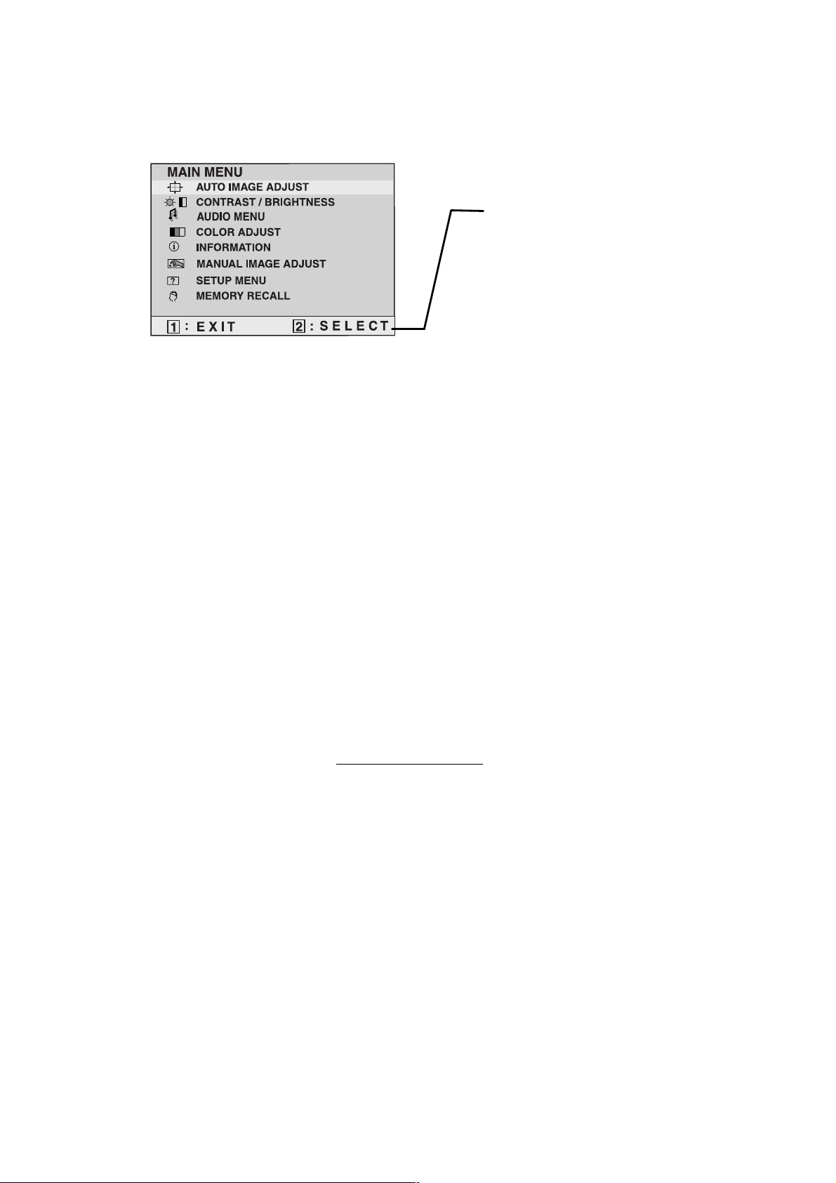
Do the following to adjust the screen image:
1
To display the Main Menu, press button [1].
The line at the bottom of the
screen tells you what you can
do next: Exit this menu or
Select the control that is
highlighted.
NOTE: All OnView menus and adjustment screens disappear automatically
after about 30 seconds. This time period is adjustable through the Setup
menu and the OSD timeout control described on page 10.
2
To highlight a control you want to adjust, press I or J to scroll up or down
the Main Menu.
3
To select the highlighted control, press button [2]. A control screen appears.
4
To adjust the control, press the up I or down J buttons.
5
To save the adjustments and exit the menu, press button [1] twice.
The following tips may help you optimize your display:
• Adjust your computer's graphic card so that it outputs a video signal 1280 x
1024 @ 60 Hz to the LCD display. (Look for instructions on “changing the
refresh rate” in your graphic card's user guide.)
• If necessary, make small adjustments using H POSITION and V POSITION
until the screen image is completely visible
. (The black border around the
edge of the screen should barely touch the illuminated “active area” of the
LCD display.)
ViewSonic VG700/VG700b 8
Page 10

Main Menu Controls
Adjust the menu items shown below by using the up Iand down Jbuttons.
Control Explanation
Auto Image Adjust
automatically sizes, centers, and fine tunes
the video signal to eliminate waviness and distortion.
Press the [2] button to obtain a sharper image.
NOTE: Auto Image Adjust works with most common video
cards. If this function does not work on your LCD display, then
lower the video refresh rate to 60 Hz and set the resolution to its
pre-set value.
Contrast
adjusts the difference between the image background
(black level) and the foreground (white level).
Brightness
Audio Menu
Volume
adjusts background black level of the screen image.
controls are explained below:
increases the volume, decreases the volume, and mutes
the audio.
Mute
temporarily silences audio output.
Color Adjust
provides several color options: preset color
temperatures and Custom User Color which allows you to adjust
red (R), green (G), and blue (B). The factory setting for this
product is 6500K (6500°Kelvin).
9300K — Adds blue to the screen image for cooler white (used
in most office settings with fluorescent lighting).
6500K — Adds red to the screen image for warmer white and
richer red.
5400K — Adds green to the screen image for a darker color.
5000K — Adds blue and green to the screen image for a darker
color.
Custom User Color
— Individual adjustments for red, green,
and blue.
1
To select color (R, G or B) press button [2].
2
To adjust selected color, pressIorJ.
3
When you are finished making all color adjustments, press
button [1] twice.
ViewSonic VG700/VG700b 9
Page 11

Control Explanation
Information
displays the timing mode (video signal input)
coming from the graphics card in your computer. See your
graphic card’s user guide for instructions on changing the
resolution and refresh rate (vertical frequency).
VESA 1280 x 1024 @ 60 Hz (recommended) means that the
resolution is 1280 x 1024 and the refresh rate is 60 Hertz.
Manual Image Adjust
H. Size
NOTE:
H./V. Position
(Horizontal Size) adjusts the width of the screen image.
Vertical size is automatic with your LCD display.
adjusts horizontal and vertical position of the
controls are explained below:
screen image. You can toggle between Horizontal and Vertical
by pressing button [2]. Horizontal moves the screen image to
the left or to the right. Vertical moves the screen image up and
down.
Fine Tune
sharpens focus by aligning the illuminated text and/
or graphic characters.
NOTE:
Fine Tune
Sharpness
Setup Menu
Language
Try the
control.
allows you to choose the language used in the menus
Auto Image Adjust
adjusts the clarity and focus of the screen image.
controls are explained below:
(see page 9) before using the
and control screens.
Resolution Notice
displays the recommended resolution for this
LCD display.
Enable allows the Resolution Notice to appear on-screen.
Disable will not allow the Resolution Notice to appear onscreen.
OSD Position allows you to move the on-screen display
menus and control screens.
ViewSonic VG700/VG700b 10
Page 12

Control Explanation
OSD Timeout
sets the length of time an on-screen display
screen is displayed. For example, with a “15 second” setting, if
a control is not pushed within 15 seconds, the display screen
disappears.
OSD Background
allows you to turn the On-Screen Display
background On or Off.
Memory Recall returns adjustments to the original factory
settings if the display is operating in a factory Preset Timing
Mode listed in this user guide.
Exception: This control does not effect changes made with the
Custom User Color control.
ViewSonic VG700/VG700b 11
Page 13

Other Information
Specifications
LCD
Input signal
Compatibility
Resolution
Power
Display area
Operating
conditions
Ty p e
Color Filter
Glass surface
Video Sync RGB analog (0.7/1.0 Vp-p, 75 ohms)
PC
Macintosh
Recommended
and supported
Voltage 100-240 VAC, 50/60 Hz (auto switch), 12V DC, 3A
Full Scan 337.92 mm (H) x 270.34 mm (V)
Temperature
Humidity
Altitude
1
17" (full 17" viewable diagonal area), TFT (Thin Film
Transistor), Active Matrix SXGA
LCD, 0.264 mm pixel pitch
RGB vertical stripe
Anti-Glare
Separate Sync
:30-82 kHz, fv:50-85 Hz
f
h
Up to 1280 x 1024 Non-interlaced
Power Macintosh up to 1280 x 1024
1280 x 1024 @ 60, 75
1024 x 768 @ 60, 70, 75, 85 Hz
800 x 600 @ 56, 60, 75, 85 Hz
640 x 480 @ 60, 75, 85 Hz
640 x 400 @ 70 Hz
720 x 400 @ 70 Hz
13.3" (H) x 10.64" (V)
+32° F to +104° F (0° C to +40° C)
10% to 90% (no condensation)
To 10,000 feet
Storage
conditions
Dimensions
Weight
Temperature
Humidity
Altitude
Physical
Net 5.3 kg (11.6 lbs)
Regulations
Power saving
modes
Preset Timing Mode
Warning:
result in permanent damage to the LCD display.
1
Macintosh computers older than G3 require a ViewSonic®, Macintosh adapter. To order an adapter,
contact ViewSonic.
Do not set the graphics card in your computer to exceed these refresh rates; doing so may
On Normal (green LED)
Active Off < 3W (orange LED)
(pre-adjusted to VESA® 1280 x 1024 @ 60 Hz)
-4° F to +140° F (-20° C to +60° C)
10% to 90% (no condensation)
To 40,000 feet
410.00 mm (W) x 421.40 mm (H) x 191.22 mm (D)
16.17" (W) x 16.59" (H) x 7.56" (D)
UL, FCC-B, E
NEMKO, SEMKO, DEMKO, FIMKO, C-UL, TCO'99 (VG700),
TCO'95 (VG700b), TUV-S, EPA, VCCI, BSMI, CB,
ISO13406-2, Gost-R, PCT (BZ02)
NERGY STAR
®
, IC-B (Doc-B), CE, MPRII,
ViewSonic VG700/VG700b 12
Page 14

Troubleshooting
No power
• Make sure power button (or switch) is ON.
• Make sure A/C power cord is securely connected to the DC power supply
and the power supply is firmly connected to the LCD display.
• Plug another electrical device (like a radio) into the power outlet to verify that
the outlet is supplying proper voltage.
Power is ON but no screen image
• Make sure the video cable supplied with the LCD display is tightly secured to
the video output port on the back of the computer. If the other end of the
video cable is not attached permanently to the LCD display, tightly secure it
to the LCD display.
• Adjust brightness and contrast.
• If you are using an Macintosh older than G3, you need a Macintosh adapter.
Wrong or abnormal colors
• If any colors (red, green, or blue) are missing, check the video cable to make
sure it is securely connected. Loose or broken pins in the cable connector
could cause an improper connection.
• Connect the LCD display to another computer.
®
• If you have an older graphics card, contact ViewSonic
adapter.
Control buttons do not work
• Press only one button at a time.
for a non-DDC
ViewSonic VG700/VG700b 13
Page 15
Customer Support
For technical support or product service, see the table below or contact your
reseller.
NOTE:
Country/
Region
United States
Canada
United Kingdom viewsoniceurope.com T: 0800 833 648
Europe, Middle
East, Baltic
countries, and
North Africa
Australia and New
Zealand
You will need the product serial number.
Web site T = Telephone
F = FAX
viewsonic.com/
support
viewsonic.com/
support
viewsoniceurope.com Contact your
viewsonic.com.au T: +61 2 9929 3955
T: (800) 688-6688
F: (909) 468-1202
T: (800) 688-6688
F: (909) 468-1202
F: (01293) 643910
reseller
F: +61 2 9929 8393
Email
service.us@
viewsonic.com
service.ca@
viewsonic.com
service.eu@
viewsoniceurope.com
service.eu@
viewsoniceurope.com
service.au@
viewsonic.com
Singapore/India
and Southeast
Asia
Other Asia/Pacific
countries
South Africa viewsonic.com/asia T: 886 2 2246 3456
viewsonic.com.sg T: 65 273 4018
F: 65 273 1566
viewsonic.com.tw T: 886 2 2246 3456
F: 886 2 8242 3668
F: 886 2 8242 3668
service.sg@
viewsonic.com
service.ap@
viewsonic.com
service.ap@
viewsonic.com
ViewSonic VG700/VG700b 14
Page 16

Cleaning the LCD Display
• MAKE SURE THE LCD DISPLAY IS TURNED OFF.
• NEVER SPRAY OR POUR ANY LIQUID DIRECTLY ONTO THE
SCREEN OR CASE.
To clean the screen:
1
Wipe the screen with a clean, soft, lint-free cloth. This removes dust and
other particles.
2
If still not clean, apply a small amount of non-ammonia, non-alcohol based
glass cleaner onto a clean, soft, lint-free cloth, and wipe the screen.
To clean the case:
1
Use a soft, dry cloth.
2
If still not clean, apply a small amount of a non-ammonia, non-alcohol
based, mild non-abrasive detergent onto a clean, soft, lint-free cloth, then
wipe the surface.
Disclaimer
®
ViewSonic
does not recommend the use of any ammonia or alcohol-based
cleaners on the LCD display screen or case. Some chemical cleaners have been
reported to damage the screen and/or case of the LCD display. ViewSonic will not
be liable for damage resulting from use of any ammonia or alcohol-based cleaners.
ViewSonic VG700/VG700b 15
Page 17

Limited Warranty
VIEWSONIC LCD DISPLAY
What the warranty covers:
®
ViewSonic
warranty period. If a product proves to be defective in material or workmanship during the warranty
period,
product or parts may include remanufactured or refurbished parts or components.
How long the warranty is effective:
ViewSonic
three (3) years for all labor from the date of the first consumer purchase.
Who the warranty protects:
This warranty is valid only for the first consumer purchaser.
What the warranty does not cover:
1. Any product on which the serial number has been defaced, modified or removed.
2. Damage, deterioration or malfunction resulting from:
a. Accident, misuse, neglect, fire, water, lightning, or other acts of nature, unauthorized product
b. Repair or attempted repair by anyone not authorized by
c. Any damage of the product due to shipment.
d. Removal or installation of the product.
e. Causes external to the product, such as electrical power fluctuations or failure.
f. Use of supplies or parts not meeting
g. Normal wear and tear.
h. Any other cause which does not relate to a product defect.
3. Removal, installation, and set-up service charges.
How to get service:
1. For information about receiving service under warranty, contact
You will need to provide your product's serial number.
2. To obtain service under warranty, you will be required to provide (a) the original dated sales slip, (b) your
name, (c) your address, (d) a description of the problem, and (e) the serial number of the product.
3. Take or ship the product freight prepaid in the original container to an authorized
service center or
4. For additional information or the name of the nearest
ViewSonic
Limitation of implied warranties:
THERE ARE NO WARRANTIES, EXPRESS OR IMPLIED, WHICH EXTEND BEYOND THE
DESCRIPTION CONTAINED HEREIN INCLUDING THE IMPLIED WARRANTY OF
MERCHANTABILITY AND FITNESS FOR A PARTICULAR PURPOSE.
Exclusion of damages:
VIEWSONIC'S LIABILITY IS LIMITED TO THE COST OF REPAIR OR REPLACEMENT OF THE
PRODUCT. VIEWSONIC SHALL NOT BE LIABLE FOR:
1. DAMAGE TO OTHER PROPERTY CAUSED BY ANY DEFECTS IN THE PRODUCT, DAMAGES
BASED UPON INCONVENIENCE, LOSS OF USE OF THE PRODUCT, LOSS OF TIME, LOSS OF
PROFITS, LOSS OF BUSINESS OPPORTUNITY, LOSS OF GOODWILL, INTERFERENCE WITH
BUSINESS RELATIONSHIPS, OR OTHER COMMERCIAL LOSS, EVEN IF ADVISED OF THE
POSSIBILITY OF SUCH DAMAGES.
2. ANY OTHER DAMAGES, WHETHER INCIDENTAL, CONSEQUENTIAL OR OTHERWISE.
3. ANY CLAIM AGAINST THE CUSTOMER BY ANY OTHER PARTY.
Effect of state law:
This warranty gives you specific legal rights, and you may also have other rights which vary from state
to state. Some states do not allow limitations on implied warranties and/or do not allow the exclusion of
incidental or consequential damages, so the above limitations and exclusions may not apply to you.
Sales outside the U.S.A. and Canada:
For warranty information and service on
contact
ViewSonic LCD Display Warranty (V3.0) Release Date: 1-29-2002
warrants its products to be free from defects in material and workmanship during the
ViewSonic
LCD displays are warranted for three (3) years for all parts including the light source and
modification, or failure to follow instructions supplied with the product.
ViewSonic
will, at its sole option, repair or replace the product with a like product. Replacement
.
ViewSonic Customer Support
ViewSonic
service center, contact
ViewSonic
.
or your local
.
ViewSonic
ViewSonic
ViewSonic
products sold outside of the U.S.A. and Canada,
dealer.
ViewSonic
’s specifications.
ViewSonic
.
ViewSonic VG700/VG700b 16
Page 18
Appendix
Safety Guidelines
Warning:
LSE0107A1240, 12V DC, SA125V-3.
CAUTION:
CAUTION:
certified for the individual country. Some examples are listed below:
This device must be operated with the original power supply, part number: 12V DC,
The socket-outlet should be installed near the equipment and should be easily accessible.
Use a power cable that is properly grounded. Always use the appropriate AC cord that is
86$ 8/
&DQDGD&6$
*HUPDQ\ 9'(
6ZLW]HUODQG 6(9
%ULWDLQ %$6(%6
-DSDQ (OHFWULF$SSOLDQFH&RQWURO$FW
IMPORTANT NOTICE CONCERNING POWER CORD SELECTION
The power cord set for this unit has been enclosed and has been selected according to the country of
destination and must be used to prevent electric shock. Use the following guidelines if it is necessary to
replace the original cord set, or if the cord set is not enclosed.
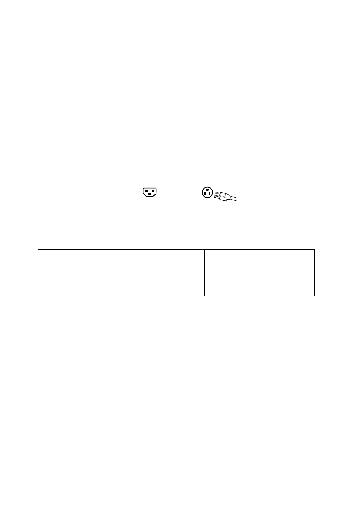
The female receptacle of the cord set must meet IEC-60320 requirements and may look like (Figure A1
below):
Figure A1
Figure A2
For the United States and Canada
In the United States and Canada the male plug is a NEMA5-15 style (Figure A2), UL Listed, and CSA
Labeled. For units which are mounted on a desk or table, type SVT or SJT cord sets may be used. For
units which sit on the floor, only SJT type cord sets may be used. The cord set must be selected according
to the current rating for your unit. Please consult the table below for the selection criteria for power cords
used in the United States and Canada.
&RUG7\SH 6L]HRI&RQGXFWRUVLQ&RUG 0D[LPXP&XUUHQW5DWLQJRI8QLW
SJT 18 AWG
16 AWG
14 AWG
SVT 18 AWG
17 AWG
10 Amps
12 Amps
12 Amps
10 Amps
12 Amps
For European Countries
In Europe you must use a cord set which is appropriate for the receptacles in your country. The cord set is HARCertified, and a special mark that will appear on the outer sheath, or on the insulation of one of the inner conductors.
AC PLUG CORD PRECAUTIONS FOR THE UNITED KINGDOM
FOR YOUR SAFETY PLEASE READ THE FOLLOWING TEXT CAREFULLY.
IF THE FITTED MOULDED PLUG IS UNSUITABLE FOR THE SOCKET OUTLET THEN THE PLUG SHOULD BE
CUT OFF AND DISPOSED OF SAFELY.
THERE IS A DANGER OF SEVERE ELECTRICAL SHOCK IF THE CUT OFF PLUG IS INSERTED INTO AN
APPROPRIATE SOCKET.
If a new plug is to be fitted, please observe the wiring code as shown below.
If in any doubt, please consult a qualified electrician.
WARNING:
IMPORTANT:
If the coloured wires of the mains lead of this appliance do not correspond with the coloured markings identifying the
terminals in your plug, proceed as follows:
The wire which is coloured GREEN-AND-YELLOW must be connected to the terminal in the plug which is marked by
the letter E or by the Earth symbol or coloured GREEN or GREEN-AND-YELLOW.
The wire which is coloured BLUE must be connected to the terminal in the plug which is marked with the letter N or
coloured BLACK. The wire which is coloured BROWN must be connected to the terminal in the plug which is marked
with the letter L or coloured RED.
If you have any questions concerning which proper power cord to use, please consult with the dealer from whom you
have purchased the product.
THIS APPLIANCE MUST BE EARTHED.
The wires in this mains lead are coloured in accordance with the following code:
Green-and-Yellow: Earth
Blue: Neutral
Brown: Live
ViewSonic VG700/VG700b 17
Page 19

Compliance Information for U.S.A.
This equipment has been tested and found to comply with the limits for a Class B digital device, pursuant to part 15
of the FCC Rules. These limits are designed to provide reasonable protection against harmful interference in a
residential installation. This equipment generates, uses, and can radiate radio frequency energy, and if not installed
and used in accordance with the instructions, may cause harmful interference to radio communications. However,
there is no guarantee that interference will not occur in a particular installation. If this equipment does cause harmful
interference to radio or television reception, which can be determined by turning the equipment off and on, the user
is encouraged to try to correct the interference by one or more of the following measures:
• Reorient or relocate the receiving antenna.
• Increase the separation between the equipment and receiver.
• Connect the equipment into an outlet on a circuit different from that to which the receiver is connected.
• Consult the dealer or an experienced radio/TV technician for help.
FCC Warning
To assure continued FCC compliance, the user must use grounded power supply cord and the provided
shielded video interface cable with bonded ferrite cores. If a BNC cable is going to be used, use only a
shielded BNC(5) cable. Also, any unauthorized changes or modifications not expressly approved by the
party responsible for compliance could void the user's authority to operate this device.
Notice for Japan
This is a Class B product based on the standard of the Voluntary Control Council for Interference from Information
Technology Equipment (VCCI). If this is used near a radio or television receiver in a domestic environment, it may
cause radio interference. Install and use the equipment according to the instruction manual.
CE Conformity for Europe
The device complies with the requirements of the EEC directive 89/336/EEC as
amended by 92/31/EEC and 93/68/EEC Art.5 with regard to “Electromagnetic
compatibility”, and 73/23/EEC as amended by 93/68/EEC Art.13 with regard to “Safety”.
ViewSonic VG700/VG700b 18
Page 20

ViewSonic® Corporation
 Loading...