

Page 1

Service Manual
ViewSonic VG511s/VG512s
Model No. VLCDS27955-3W/4W
15” Color TFT LCD Display
ViewSonic
(VG511s/VG512s_SM_742 Rev. 1a Apr. 2004)
381 Brea Canyon Road, Walnut, California 91789 USA - (800) 888-8583
Page 2
Copyright
Copyright
reproduced, transmitted, transcribed, stored in a retrieval system, or translated into any language or
computer language, in any form or by any means, electronic, mechanical, magnetic, optical, chemical,
manual or otherwise, without the prior written permission of ViewSonic Corporation.
Disclaimer
ViewSonic makes no representations or warranties, either expressed or implied, with respect to the
contents hereof and specifically disclaims any warranty of merchantability or fitness for any particular
purpose. Further, ViewSonic reserves the right to revise this publication and to make changes from time
to time in the contents hereof without obligation of ViewSonic to notify any person of such revision or
changes.
Trademarks
Optiquest is a registered trademark of ViewSonic Corporation.
ViewSonic is a registered trademark of ViewSonic Corporation.
All other trademarks used within this document are the property of their respective owners.
2004 by ViewSonic Corporation. All rights reserved. No part of this publication may be
¤
Revision History
Revision Date Description Of Changes Approval
1a 04/14/04 Initial Release DCN-3756 Angela Lu
ViewSonic Corporation Confidential
i
-
Do Not Copy VG511s
VG512s
Page 3

TABLE OF CONTENTS
1. Precautions and Safety Notices
2. Specification
3. Front Panel Function Control Description
4. Circuit Description
5. Adjusting Procedure
6. Trouble Shooting Flow Chart
7. Recommended Spare Parts List
8. Exploded Diagram And Spare Parts List
9. Block Diagram
10. Schematic Diagrams
11. PCB Layout Diagrams
1
2
5
7
8
9
14
22
24
25
32
ViewSonic Corporation Confidential
ii
-
Do Not Copy VG511s
VG512s
Page 4

1. Precautions and Safety Notices
Prior to using this manual, please ensure that you have carefully followed all the procedures outlined in the user manual
for this product.
Read all of these instructions.
Save these instructions for later use.
Follow all warnings and instructions marked on the product.
Do not use this product near water.
This display should be installed on a solid horizontal base.
When cleaning, use only a neutral detergent cleaner with a soft damp cloth. Do not spray with liquid or aerosol cleaners.
Do not expose this display to direct sunlight or heat. Hot air may cause damage to the cabinet and other parts.
Adequate ventilation must be maintained to ensure reliable and continued operation and to protect the display from
overheating. Do not block ventilation slots and openings with objects or install the display in a place where
ventilation may be hindered.
Do not install this display near a motor or transformer where strong magnetism is generated. Images on the display
will become distorted and the color irregular.
Do not allow metal pieces or objects of any kind fall into the display from ventilation holes.
Slots and openings in the cabinet and the back or bottom are provided for ventilation, to ensure reliable operation of
the product and to protect it from overheating, those openings muse not be blocked or covered.
The openings should never be blocked by placing the product on a bed, sofa, rug, or other similar surface.
This product should never be placed near or over a radiator or heat register.
This product should not be placed in a built-in installation unless proper ventilation is provided.
ViewSonic Corporation Confidential
1
-
Do Not Copy VG511s
VG512s
Page 5

2. Specification
2.1. PRODUCT SPECIFICATIONS
LCD panel type
Displayable resolution
Pixel dimension
LCD display color
OSD control
15.0” TFT (15.0” Diagonal)
XGA 1024 x 768 maximum
0.297 mm horizontal x 0.297 mm vertical
16.8M Colors Max.
AUTO CONFIG, BRIGHTNSS,
CONTRAST, COLOR (R, G, B, BLACK LEVEL ADJUST),
POSITION(H-POSITION, V-POSITION ),IMAGE (PHASE,
CLOCK ),
SETUP MENU (RESET,OSD POSITION, SYSTEM INFO )
Manualcontrolbuttons
Viewing angle
Tilt
Contrast ratio
Brightness
Response time
Active display area
AC/DC adapter
MENU, Select, Adjust(up,down), Power.Mute,+,Horizontal: ± 60 , Vertical: -45~+55.
+20°, -5°.
450:1 (typ) , 300:1 (min)
250
cd/m2
(typ), 200
cd/m2
(min)
16ms (typ) tr+tf , 23ms (max) tr+tf
304.1 mm (H) x228.1mm (V)
Input: AC 100 ~ 240V, 50 ~ 60 Hz
Output: +12 V DC.
Input signal
Video: Analog 0.7 Vp-p. 75 ohms
Sync. : TTL Level, Positive/ Negative, Separate Sync.
Input connector
Power management
Dimensions ( WxHxD )
Weight
15 Pin D-Sub.
yes
34.6 cm x 35.5 cm x 15.6 cm.
2.7 kgs. (LCD Module only)
3.4kgs. (unit)
Accessory
Temperature
Color temp (white)
VGA cable, AC/DC adapter, power cord.
Operation : 0 ~ 50°C
Storage : -20 ~ 60°C
White x 0.313±0.03 , white y 0.329±0.03
ViewSonic Corporation Confidential
2
-
Do Not Copy VG511s
VG512s
Page 6
2.2. FACTORY SUPPORTING MODES
Prim
ary Preset VESA 1024 x 768 @ 60 Hz
Factory Preset Modes
1. 640 x 350 @ 70Hz, 31.5kHz
2. 640 x 480 @ 60Hz, 31.5kHz
3. 640 x 480 @ 67Hz, 35.0kHz
4. 640 x 480 @ 75Hz, 37.5kHz
5. 640 x 480 @ 72Hz, 37.9kHz
6. 720 x 400 @ 70Hz, 31.5kHz
7. 800 x 600 @ 56Hz, 35.1kHz
8. 800 x 600 @ 60Hz, 37.9kHz
9. 800 x 600 @ 75Hz, 46.9kHz
10. 800 x 600 @ 72Hz, 48.1kHz
11. 800 x 600 @ 85Hz, 53.7kHz
12. 832 x 624 @ 75Hz, 49.7kHz
13. 1024 x 768 @ 60Hz, 48.4kHz
14. 1024 x 768 @ 70Hz, 56.5kHz
15. 1024 x 768 @ 72Hz, 58.1kHz
16.1024 x 768 @ 75Hz, 60.0kHz
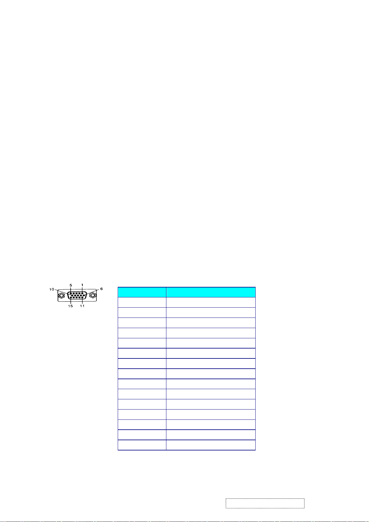
2.3. D-SUB CONNECTOR
This section describes the pin assignment of the LCD’s video connector.
It is called 15 Pin Mini D-sub Connector.
Pin NO.
1
2
3
4
5
6
7
8
9
10
11
12
13
14
15
Signal Connector
Red Video Signal
Green Video Signal
Blue Video Signal
N.C.
Ground
Ground
Ground
Ground
+5V
Ground
N.C.
DDC data
Horizontal sync signal
Vertical sync signal
DDC clock
ViewSonic Corporation Confidential
3
-
Do Not Copy VG511s
VG512s
Page 7
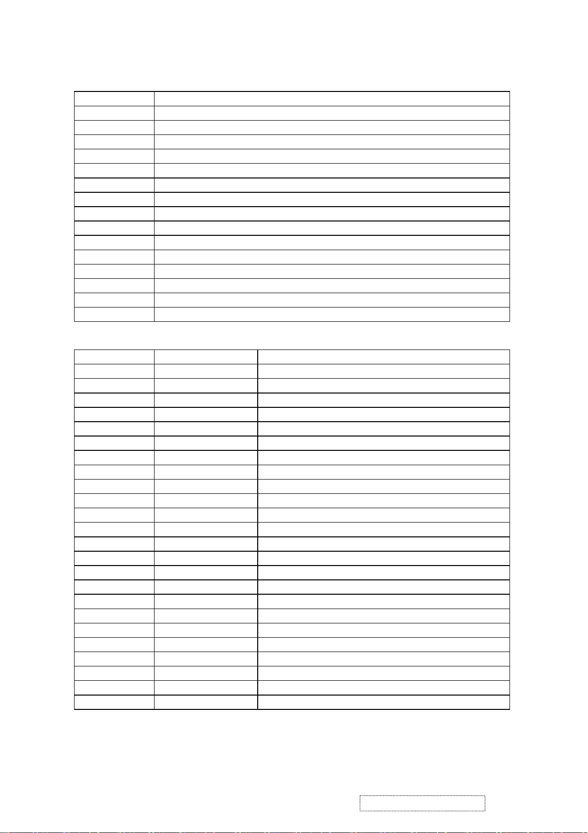
Table 3.1: 15 pin D-sub connector pin assignment
Pin Number Pin Function
1 Red video input
2 Green video input
3 Blue video input
4 No Connection
5 Ground
6 Red video ground
7 Green video ground
8 Blue video ground
9 +5V
10 Ground
11 No connection
12 (SDA)
13 Horizontal sync (Composite sync)
14 Vertical sync
15 (SCL)
Table 3.2: 24 pin DVI-D connector pin assignment
Pin No. Signal Name Description
1 RX2- TMDS negative differential input, channel 2
2 RX2+ TMDS positive differential input, channel 2
3 GND Logic Ground
4 Reserved 4 Reserved. No connection
5 Reserved 5 Reserved. No connection
6 DDC-CLK DDC2B Clock
7 DDC-DAT DDC2B Data
8 Reserved 8 Reserved. No connection
9 RX1- TMDS negative differential input, channel 1
10 RX1+ TMDS positive differential input, channel 1
11 GND Logic Ground
12 Reserved 12 Reserved. No connection
13 Reserved 13 Reserved. No connection
14 VCCX Power
15 GND Logic Ground
16 SENS SENSE Pin, Pull High
17 RX0- TMDS negative differential input, channel 0
18 RX0+ TMDS positive differential input, channel 0
19 GND Logic Ground
20 Reserved 20 Reserved. No connection
21 Reserved 21 Reserved. No connection
22 GND Logic Ground
23 RXC+ TMDS positive differential input, reference clock
24 RXC- TMDS negative differential input, reference clock
ViewSonic Corporation Confidential
4
-
Do Not Copy VG511s
VG512s
Page 8
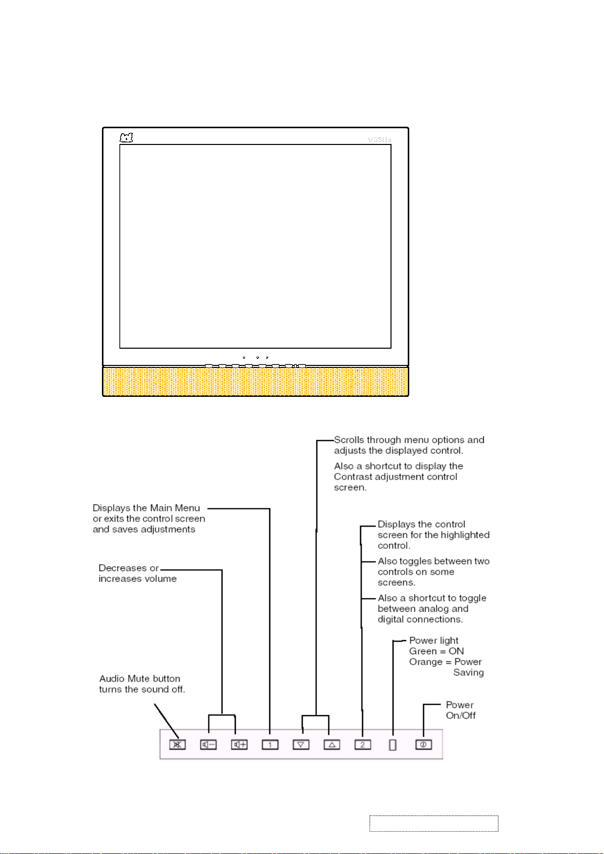
3. Front Panel Function Control Description
3.1 Location of Controls
ViewSonic Corporation Confidential
5
-
Do Not Copy VG511s
VG512s
Page 9

1) MENU:
Enter to the OSD adjustment menu. It also used for go back to previous menu for sub-menu,
and the change data don’t save to memory.
2) SELECT:
To confirm the current selection. It also used for go back to previous menu for sub-menu,
and the change data will be save to memory.
ADJUST ▼:
3)
To scroll up in sub menu or to increase value of selected item.
4) ADJUST ▲:
To scroll down in sub menu or to decrease value of selected item
5) POWER SWITCH
Pushing the power switch will turn the monitor on. Pushing it again to turn the monitor off.
6) POWER INDICATOR
The LED will light with green color in normal on state, and will
light with orange color in power saving mode.
7) BRIGHTNESS/CONTRAST:
Press button UP/DOWN
8) AUTOIMAGEADIUST:
press button [2]
9) OSD LOCK AND UNLOCK:
press two buttons [1] & [UP] simultaneously for 10 seconds
10) POWER LOCK AND UNLOCK:
press two buttons [1] & [DOWN] simultaneously for 10 seconds
11) ALL RESET:
First,power off the monitor, un-plug the AC cord, then press [2] key at the same time and plug
the AC cord
12) FACTORY MODE:
First,power off the monitor, un-plug the AC cord and be sure the signal cable is connected (D-sub
connected),then press [ ] key at the same time and plug the AC cord.
13) RUN-IN MODE:
▲
First ,power off the monitor, up-plug the AC cord and be sure the cable is not connected(D-Sub
not connected),then press [1] key at the same time and plug the AC cord.
14) AUTO COLOR:
press three buttons [1] & [up] & [down], this function only use for 1024x768 60hz patten 42/of
Chroma 2135 signal generator.
NOTE:
chroma Patten 42
ViewSonic Corporation Confidential
6
-
Do Not Copy VG511s
VG512s
Page 10

4. Circuit Description
WORKING THEOREM
A. DC-DC CONVERTER
This brick converts the 12V input voltage to 5V for panel use and 3.3V for controller use.
It consists of a PWM IC (AP1501), flywheel Diode (D1), buck choke (L2), and capacitor (C70,71).
AP1501 is a PWM generator working at 150Khz.
Self protection features include a two stage frequency reducing current limit for the output
switch and an over temperature shutdown for complete protection under fault condition.
B. A/D converter
The MST 9030A is a highly integrated TFT LCD controller chip with the latest MST advanced imageprocessing technology
and an integrated ADC/PLL. The MST 9030A has advanced programmable non-linear parametric
cubic based scaling engine with proprietary sharpness adjustment and text enhancement. MST9030A supports both analog
and digital interfaced inputs with an internal ADC/PLL.
The MST9030A has robust handling of a wide variety of TFT LCD panels and strong support of standard
or non-standard input timings.
. Integrated high speed triple 8-bit ADC/PLL support up to 140MHz for XGA-75Hz
. Advanced image processing with proprietary non linear parametric cubic based scaling engineSupport dual interface
with an integrated ADC/PLL
. Robust auto configuration for input mode detection and clock frequency and phase recovery for standard or
nonstandard input timing
. Support video processing with on-chip 2D de-interlacing and color space conversion
. Support programmable Gamma Correction
. GPIO pins for flexible system design
D. MCU:
The MTV312MV64AJ micro-controller is an 8051 CPU core embedded device specially tailored to LCD monitor
applications. It include an 8051 CPU core, 1024-byte SRAM, 14 built-in PWM DACs, VESA DDC interface,
4 channel 6bit A/D converter, a 64 K-byte internal program Flash-ROM .
ViewSonic Corporation Confidential
7
-
Do Not Copy VG511s
VG512s
Page 11
5. Adjusting Procedure
First, power off the monitor, un-plug the AC cord and be sure the signal cable is
connected(D-sub connected) , then press “2” key at the same time and plug the AC cord to factory.
ViewSonic Corporation Confidential
8
-
Do Not Copy VG511s
VG512s
Page 12
N
N
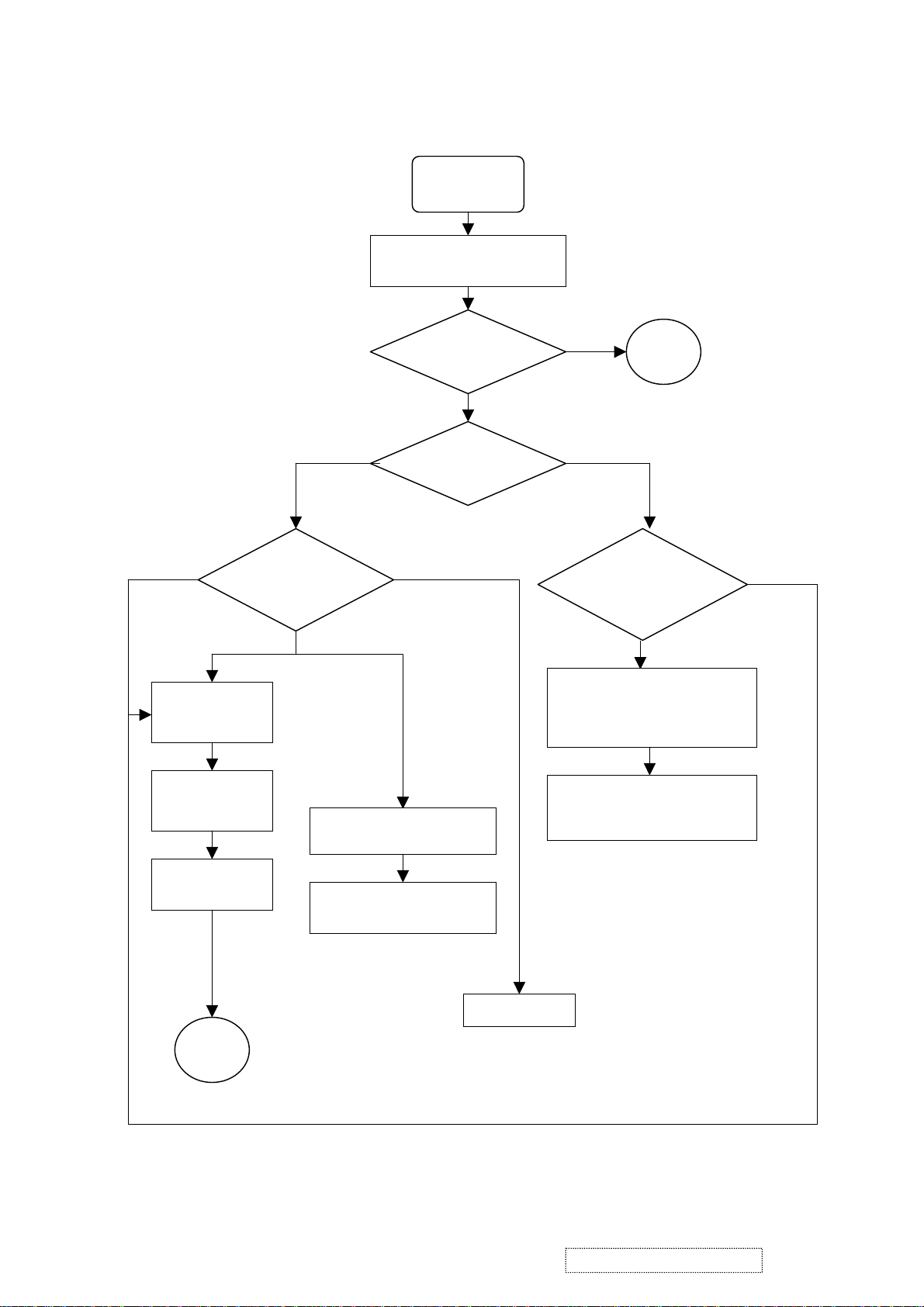
6. Trouble Shooting Flow Chart
START
Use Analog Native mode
(Window Pattern )
Green + Orange
Check DC power
12V,5V,3.3V,2.5V
,MCU 5V
Check MCU
crystal
Power LED
Picture
visible?
o
Off On
Backlight
on?
Green
Orange
(1)Panel no power
(2)Panel cable not connected
(3)H/V sync process to panel
OK
Check Scaler
(1)Check Scaler H/V sync correct?
(2)Measure at Scaler side
Yes
Green LED &
key pad work?
A
o
Yes
Check MCU or
Reprogram MCU
(1)Scaler no power
(2)Scaler changed no OSC
Check Inverter
B
ViewSonic Corporation Confidential
9
-
Do Not Copy VG511s
VG512s
Page 13

N
N
N
No N
N
N
N
Picture Visible
A
Picture
jumping
Picture
over-scaler
Yes
Picture only
appear one
C
Picture normal
then panel
Panel power abnormal
o
o
o
o
Stable
picture &
Yes
Yes
Absent of H/V
sync of scaler O/P
or short CKT
(1)Check OSD
information if mode
error
(2)H/V sync input
tolerance too big
burn
Yes
o
o
Backlight off
after one
second
Yes
(1)DC power source no enough
(2)Backlight wire short CKT
(3)Inverter shut down
Scaler O/P CKT not assembled ok
Yes
Picture
distortion
Yes
Incorrect panel type or cable
OSD
distorted
o
ViewSonic Corporation Confidential
10
-
Do Not Copy VG511s
VG512s
Page 14

MCU
N
N
N
N
p
N
N
N
N
prog
B
o pulse
Check Reset CKT
Check Reset
waveform when
power on
A pulse to > 4.75V
Check if O/P
short to GND
Yes
MCU not
Crystal no
MCU 5V
=4.75~5.25V
Check DC 5V CKT
Yes
rammed
o
OSC
o
o
Reflow
Yes
Yes
Re-programming
(1)MCU not put well
(2)Crystal bad
(3)Cap of crystal
too big/small
o
Check if MCU
pin short or bend
o
Check if socket
pin bend
If input over
MCU 5+0.25V
o
o
MCU bad
Yes
Yes
Yes
Check 4 corner are shorted
or not
robe to measure
Not allowed
Change socketBe carefully when using
ViewSonic Corporation Confidential
11
-
Do Not Copy VG511s
VG512s
Page 15

g
r
N
p
N
N
N
Picture Abnormal but Stable & size correct
C
Shadowing
Noisy
o Yes
Yes
o
Check VGA cable
(1)Too long?
(2)Quality no good?
Measure R/G/B input
use block pattern
Color absent
or wron
colo
Use 256 gray scale with
R/G/B white
Segment for
ecific color
s
o
Use 32 or 64 gray scale
Yes
Scaler O/P short or
open
(1) VGA cable quality
bad
(2) Power(3.3V/2.5V)
have big noise
oise at certain scale for
more than one color
TTL O/P short or open
ViewSonic Corporation Confidential
12
-
Do Not Copy VG511s
VG512s
Page 16

N
N
N
N
NO POWER
D
Use multi-meter to measure
& turn on system
12V ok ?
Remove adapter
Measure adapter only
Remove
L11/L15/L16/L25
o
Yes
Yes
Adapter ok
5V ok ?
+12V->5V
regulator CKT no
work
Yes
o
5V ok ?
Yes
+5V short to
GND or 3.3V
3.3V/2.5V
ok ?
o
3.3V/2.5V short
to GND
Yes
MCU 3.3V bad
PC 5V/DC 3.3V
CKT not correct
Change adapter
o
Measure +12V to
GND
ViewSonic Corporation Confidential
13
-
Do Not Copy VG511s
VG512s
Page 17

7. Recommended Spare Parts List
VG511s RSPL VSA-M
Item Location ViewSonic P/N Reference P/N Description Universal number#
1 BASE PL-PS-0715-0978 GSTN-2916D8F--- BASE
2 BASE FRONT COVER M-CV-0830-2500 GCOVD2552D8F--- BASE FRONT COVER
3 BASE-BACK COVER M-CV-0830-2501 GCOVD2553D8F--- BASE-BACK COVER
4 BASE METAL M-BK-0805-0032 LANGF2132D8---- BASE METAL
5 CUSHION-C P-FM-0602-0832 PCUSG1634D8---- CUSHION-C
6 CUSHION-A P-FM-0602-0833 PCUSG1633D8---- CUSHION-A
7 CUSHION-B P-FM-0602-0834 PCUSG1632D8---- CUSHION-B
8 ID LABEL M-LB-0813-0936 PISLV0238D8---- ID LABEL
9 HINGE ASSEMBLY M-MS-0808-9112 MHNGM0046D8---- HINGE ASSEMBLY
10 SPEAKER E-SK-0412-0085 RSPKCL032D88FG- SPEAKER
11 CAB-A M-MS-0808-9233 GCABA2331D8FT-A CAB-A
12 CAB-B M-MS-0808-9122 GCABB1852D8F--- CAB-B
13 KNOB PL-NB-0707-1072 JKNBP2358D8F--- KNOB
14 LENS M-MS-0808-9115 HDECP1987D8F--- LENS
15 BACK COVER C-BC-0302-0561 GCOVD2551D8F--- BACK COVER
16 VE-LOGO M-MS-0808-9123 HBDGE1388D8---- VE-LOGO
17 VESA METAL M-BK-0805-0033 LANGF2131D8---- VESA METAL
18 D-SUB METAL M-BK-0805-0034 LANGF2133D8---- D-SUB METAL
19 VESA GUM M-MS-0808-9117 PGUM-1124D8---- VESA GUM
20 VIEWSONIC TEXT LOGO M-MS-0808-9118 HBDGE1389D8---- VIEWSONIC TEXT LOGO
21 LOGO PLATE (BIRDS LOGO) M-MS-0808-9119 HBDGE1390D8---- LOGO PLATE (BIRDS LOGO)
22 BOSS FOR D-SUB AND DVI M-MS-0808-5840 LBOSM1069D8---- BOSS FOR D-SUB AND DVI
23 KENSINGTON BRACKET M-BK-0805-0012 LANGF2063D8---A KENSINGTON BRACKET
24 OSD-SW BOARD ASS'Y B-CB-0206-0179 DPWBN5548T8---- OSD-SW BOARD ASS'Y
25 AC ADAPTOR (VSC 12V/3.3A) A-AD-0114-0212 RUNTP5579D8---- AC ADAPTOR (VSC 12V/3.3A)
26 INF FILE DEVICE A-CD-VG511S DDSKC0045D8---- INF FILE DEVICE
27 USER'S MANUAL A-UG-0107-0518 TINSE3076D8---- USER'S MANUAL
28 SIGNAL CABLE A-VC-0101-0271 QCODS1584D8D--- SIGNAL CABLE
29 AUDIO CABLE A-AU-0120-0034 QCODK0030D8D--- AUDIO CABLE
30 POWER CORD A-PC-0106-0180 QACC-1126D8D--- POWER CORD
31 POWER CORD A-PC-0106-0181 QACC-1228T8D-F- POWER CORD(EU 1.8M BLACK)
32 PACKING M-MS-0808-9120 SPAKA6557D8---- PACKING
33 CARTON P-BX-0601-0953 SPAKC3630D8---B CARTON
34 AU PANEL (15") M-LCD-0826-0214 VVLM150XN05---- AU PANEL (15")
35 I/F BOARD ASS'Y B-IF-0222-0058 DPWBN5574T8---- I/F BOARD ASS'Y
36 INVERTER BOARD B-SB-0221-0407 RUNTP5463T8---- INVERTER BOARD
37 MAIN METAL M-BK-0805-0035 LANGF2130D8---- MAIN METAL
38 I/F SHIELD M-BK-0805-0036 PSLDM6569D8---- I/F SHIELD
39 INVERTER SHIELD M-BK-0805-0037 PSLDM6568D8---- INVERTER SHIELD
40 FFC CABLE (45 PIN) A-VC-0101-0358 QCODS1695T8---- FFC CABLE (45 PIN)
41 FFC CABLE (30 PIN) M-FC-0809-0796 QCODP1196D8---- FFC CABLE (30 PIN)
42 INVERTER WIRE M-WR-0828-0749 QCODP1195D8---- INVERTER WIRE
43 AUDIO WIRE M-WR-0828-6015 QCNWS0904-8038- SPEAKER WIRE
44 OSD-SW WIRE M-WR-0828-0750 QCNWS090B-8014- OSD-SW WIRE
F1
45
46 U1 (SCALER IC) E-IC-0450-0023 VSIMST9030A---D
47 U7 (44 PIN IC SOCKET) M-MS-0808-8003 QSOCI1642T844-48 Y1.(12.0 MHZ), E-X-0415-0143 RCRSL1259T8---- OSCILLATOR (11.059MHZ)
49 Y2.(11.059MHZ) E-X-0415-0141 RCRSL1114T8---- OSCILLATOR (14.318MHZ)
U8
50
51 CON5 (45 PIN PLUG) M-FC-0809-0797 QCNCP2107D8---52 CON6 (30 PIN PLUG) M-FC-0809-0789 QCNCP2106D8----
E-FS-0410-0099 QFS-Z402F-81UAA
E-IC-0401-2584 VSI24C16-------
FUSE 4A
SCALER MST9030A
44PIN PLCC IC SOCKET
EEPROM
45 PIN CONNECTOR
30 PIN CONNECTOR
ViewSonic Corporation Confidential
14
-
Do Not Copy VG511s
VG512s
Page 18

VG512s RSPL VSA-M
Item Location ViewSonic P/N Reference P/N Description Universal number#
1 BASE PL-PS-0715-0978 GSTN-2916D8F--- BASE
2 BASE FRONT COVER M-CV-0830-2500 GCOVD2552D8F--- BASE FRONT COVER
3 BASE-BACK COVER M-CV-0830-2501 GCOVD2553D8F--- BASE-BACK COVER
4 BASE METAL M-BK-0805-0032 LANGF2132D8---- BASE METAL
5 CUSHION-C P-FM-0602-0832 PCUSG1634D8---- CUSHION-C
6 CUSHION-A P-FM-0602-0833 PCUSG1633D8---- CUSHION-A
7 CUSHION-B P-FM-0602-0834 PCUSG1632D8---- CUSHION-B
8 ID LABEL M-LB-0813-0937 PISLV0239D8---- ID LABEL
9 HINGE ASSEMBLY M-MS-0808-9112 MHNGM0046D8---- HINGE ASSEMBLY
10 SPEAKER E-SK-0412-0085 RSPKCL032D88FG- SPEAKER
11 CAB-A C-FP-0301-0970 GCABA2331D8FT-B CAB-A
12 CAB-B M-MS-0808-9122 GCABB1852D8F--- CAB-B
13 KNOB PL-NB-0707-1072 JKNBP2358D8F--- KNOB
14 LENS M-MS-0808-9115 HDECP1987D8F--- LENS
15 BACK COVER C-BC-0302-0561 GCOVD2551D8F--- BACK COVER
16 VE-LOGO M-MS-0808-9123 HBDGE1388D8---- VE-LOGO
17 VESA METAL M-BK-0805-0033 LANGF2131D8---- VESA METAL
18 D-SUB METAL M-BK-0805-0034 LANGF2133D8---- D-SUB METAL
19 VESA GUM M-MS-0808-9117 PGUM-1124D8---- VESA GUM
20 VIEWSONIC TEXT LOGO M-MS-0808-9118 HBDGE1389D8---- VIEWSONIC TEXT LOGO
21 LOGO PLATE (BIRDS LOGO) M-MS-0808-9119 HBDGE1390D8---- LOGO PLATE (BIRDS LOGO)
22 BOSS FOR D-SUB AND DVI M-MS-0808-5840 LBOSM1069D8---- BOSS FOR D-SUB AND DVI
23 KENSINGTON BRACKET M-BK-0805-0012 LANGF2063D8---A KENSINGTON BRACKET
24 OSD-SW BOARD ASS'Y B-CB-0206-0179 DPWBN5548T8---- OSD-SW BOARD ASS'Y
25 AC ADAPTOR (VSC 12V/3.3A) A-AD-0114-0212 RUNTP5579D8---- AC ADAPTOR (VSC 12V/3.3A)
26 INF FILE DEVICE A-CD-VG512S DDSKC0046D8---- INF FILE DEVICE
27 USER'S MANUAL A-UG-0107-0519 TINSE3089D8---- USER'S MANUAL
28 SIGNAL CABLE A-VC-0101-0271 QCODS1584D8D--- SIGNAL CABLE
29 AUDIO CABLE A-AU-0120-0034 QCODK0030D8D--- AUDIO CABLE
30 POWER CORD A-PC-0106-0180 QACC-1126D8D--- POWER CORD
31 POWER CORD A-PC-0106-0181 QACC-1228T8D-F- POWER CORD(EU 1.8M BLACK)
32 PACKING M-MS-0808-9120 SPAKA6557D8---- PACKING
33 CARTON P-BX-0601-0954 SPAKC3630D8---A CARTON
34 AU PANEL (15") M-LCD-0826-0214 VVLM150XN05---- AU PANEL (15")
35 I/F BOARD ASS'Y B-IF-0222-0058 DPWBN5574T8---- I/F BOARD ASS'Y
36 INVERTER BOARD B-SB-0221-0407 RUNTP5463T8---- INVERTER BOARD
37 MAIN METAL M-BK-0805-0035 LANGF2130D8---- MAIN METAL
38 I/F SHIELD M-BK-0805-0036 PSLDM6569D8---- I/F SHIELD
39 INVERTER SHIELD M-BK-0805-0037 PSLDM6568D8---- INVERTER SHIELD
40 FFC CABLE (45 PIN) A-VC-0101-0358 QCODS1695T8---- FFC CABLE (45 PIN)
41 FFC CABLE (30 PIN) M-FC-0809-0796 QCODP1196D8---- FFC CABLE (30 PIN)
42 INVERTER WIRE M-WR-0828-0749 QCODP1195D8---- INVERTER WIRE
43 AUDIO WIRE M-WR-0828-6015 QCNWS0904-8038- SPEAKER WIRE
44 OSD-SW WIRE M-WR-0828-0750 QCNWS090B-8014- OSD-SW WIRE
F1
45
46 U1 (SCALER IC) E-IC-0450-0023 VSIMST9030A---D
47 U7 (44 PIN IC SOCKET) M-MS-0808-8003 QSOCI1642T844-48 Y1.(12.0 MHZ), E-X-0415-0143 RCRSL1259T8---- OSCILLATOR (11.059MHZ)
49 Y2.(11.059MHZ) E-X-0415-0141 RCRSL1114T8---- OSCILLATOR (14.318MHZ)
U8
50
51 CON5 (45 PIN PLUG) M-FC-0809-0797 QCNCP2107D8---52 CON6 (30 PIN PLUG) M-FC-0809-0789 QCNCP2106D8----
E-FS-0410-0099 QFS-Z402F-81UAA
E-IC-0401-2584 VSI24C16-------
FUSE 4A
SCALER MST9030A
44PIN PLCC IC SOCKET
EEPROM
45 PIN CONNECTOR
30 PIN CONNECTOR
ViewSonic Corporation Confidential
15
-
Do Not Copy VG511s
VG512s
Page 19

VG511s-1 BOM
Item ViewSonic P/N Ref. P/N Description Location Universal number# Q'ty
1 PL-PS-0715-0978 GSTN-2916D8F--- BASE BASE 1
2 M-CV-0830-2500 GCOVD2552D8F--- BASE FRONT COVER BASE FRONT COVER 1
3 M-CV-0830-2501 GCOVD2553D8F--- BASE-BACK COVER BASE-BACK COVER 1
4 M-BK-0805-0032 LANGF2132D8---- BASE METAL BASE METAL 1
5 M-MS-0808-9382 PCUSG1634D8---- CUSHION-C CUSHION-C 1
6 M-MS-0808-9383 PCUSG1633D8---- CUSHION-A CUSHION-A 2
7 P-FM-0602-0834 PCUSG1632D8---- CUSHION-B CUSHION-B 1
8 M-MS-0808-9112 MHNGM0046D8---- HINGE ASSEMBLY HINGE ASSEMBLY 1
9 #N/A XBSSE30P06000-- SCREW FOR HINGE*4,FOR BASE METAL*4 8
10 E-SK-0412-0085 RSPKCL032D88FG- SPEAKER SPEAKER 1
11 M-MS-0808-9233 GCABA2331D8FT-A CAB-A CAB-A 1
12 M-MS-0808-9122 GCABB1852D8F--- CAB-B CAB-B 1
13 PL-NB-0707-1072 JKNBP2358D8F--- KNOB KNOB 1
14 M-MS-0808-9115 HDECP1987D8F--- LENS LENS 1
15 C-BC-0302-0561 GCOVD2551D8F--- BACK COVER BACK COVER 1
16 M-MS-0808-9123 HBDGE1388D8---- VE-LOGO VE-LOGO 1
17 M-BK-0805-0033 LANGF2131D8---- VESA METAL VESA METAL 1
18 M-BK-0805-0034 LANGF2133D8---- D-SUB METAL D-SUB METAL 1
19 M-MS-0808-9117 PGUM-1124D8---- VESA GUM VESA GUM 4
20 M-MS-0808-9118 HBDGE1389D8---- VIEWSONIC TEXT LOGO VIEWSONIC TEXT LOGO 1
21 M-MS-0808-9119 HBDGE1390D8---- LOGO PLATE (BIRDS MARK) LOGO PLATE (BIRDS MARK) 1
22 #N/A XEBSB30P14000-- CAB-B&CAB-A CAB-B&CAB-A 2
23 #N/A XBPSB40P10JS0-- METAL*4 HINGE SUPPORT WITH MAIN METAL*4 4
24 #N/A LX-BZ1721D8---- SCREW FOR CAB-B WITH PANEL*4 4
25 #N/A LX-BZ1726D8---- SCREW PANEL WITH MAIN METAL 4
26 #N/A LX-BZ1724D8---- SCREW MAIN METAL WITH CAB-B 2
27 #N/A PISLV0231D8---- WASHER WASHER 4
28 M-LB-0813-0936 PISLV0238D8---- ID LABEL ID LABEL 1
29 M-SCW-0824-6738 XEPSN26P06000-- SCREW FOR KEY PCB 1
30 #N/A XBSSE30P06000-- SCREW FOR D-SUB&CAB-B 2
31 #N/A XBSSD30P04000-- SCREW FOR D-SUB METAL 4
32 #N/A XBMSD30P05000-- SCREW FOR I/F BOARD*4,INFERTER BOARD*3 7
33 #N/A PCUSS1500D8---- CUSHION FOR CAB-A CUSHION FOR CAB-A 1
34 M-BK-0805-0012 LANGF2063D8---A KENSINGTON BRACKET KENSINGTON BRACKET 1
35 #N/A LX-TZ0001D8SC-A SPEAKER SCREW SPEAKER SCREW 4
36 #N/A LX-BZ1717D8---- SCREW FOR INVERTER*4,I/F SHIELD*6 10
37 #N/A PCUSG1636D8---- EVA LABEL EVA FOR VESA METAL 1
38 P-FM-0602-0835 PCUSG1638D8---- CUSHION FOR CAB-B CUSHION FOR CAB-B 1
39 A-AD-0114-0212 RUNTP5579D8---- AC ADAPTOR (VSC 12V/3.3A) AC ADAPTOR (VSC 12V/3.3A) 1
40 #N/A TLAB-5532D8---- MODEL LABEL MODEL LABEL 1
41 A-UG-0107-0518 TINSE3076D8---- USER'S MANUAL USER'S MANUAL 1
42 A-CD-VG511S DDSKC0045D8---- INF FILE DEVICE INF FILE DEVICE 1
43 A-VC-0101-0271 QCODS1584D8D--- SIGNAL CABLE SIGNAL CABLE 1
44 A-PC-0106-0180 QACC-1126D8D--- AC POWER CORD AC POWER CORD 1
45 M-LB-0813-0527 TLABZ3903D8---- UPC LABEL UPC LABEL 1
46 A-AU-0120-0034 QCODK0030D8D--- AUDIO CABLE AUDIO CABLE 1
47 A-PC-0106-0181 QACC-1228T8D-F- BLACK) POWER CORD (EU 1.8M BLACK) 1
48 #N/A TLAB-5523D8---- S/N LABEL S/N LABEL 1
49 M-MS-0808-9120 SPAKA6557D8---- PACKING PACKING 1
50 P-BX-0601-0953 SPAKC3630D8---B CARTON CARTON 1
51 M-MS-0808-8796 SSAKH1343D8-T-- BAG BAG 1
52 #N/A SPAKW1204D8---- PALLET PALLET 1
53 M-MS-0808-8401 PISL-1245D8---- PROTECT SHEET PROTECT SHEET 1
54 M-MS-0808-5875 SPAKK1703T8Z--- CONNER PAPER CONNER PAPER
55 #N/A SPAKK6322D8---- CONNER PAPER CONNER PAPER
56 #N/A SPAKK6357D8---- CONNER PAPER CONNER PAPER
57 #N/A SPAKK6364D8---- CONNER PAPER CONNER PAPER
58 #N/A ZTAPEY010G080-- TAPE TAPE W=100MM FOR EPS 80
59 #N/A ZTAPEY030G045-- TAPE TAPE FOR CAB-A CORNER 160
(4 per pallet)
(2 per pallet)
(4 per pallet)
(2 per pallet)
VG511s-1 LCD BOM
Item ViewSonic P/N Ref. P/N Description Location Universal number# Q'ty
1 M-LCD-0826-0214 VVLM150XN05---- AU PANEL (15") AU PANEL (15") 1
2 B-IF-0222-0058 DPWBN5574T8---- I/F BOARD ASS'Y I/F BOARD ASS'Y 1
3 B-SB-0221-0407 RUNTP5463T8---- INVERTER BOARD INVERTER BOARD 1
4 B-CB-0206-0179 DPWBN5548T8---- OSD-SW BOARD ASS'Y OSD-SW BOARD ASS'Y 1
5 M-BK-0805-0035 LANGF2130D8---- MAIN METAL MAIN METAL 1
6 M-BK-0805-0036 PSLDM6569D8---- I/F SHIELD I/F SHIELD 1
7 M-BK-0805-0037 PSLDM6568D8---- INVERTER SHIELD INVERTER SHIELD 1
8 #N/A PISLS1234D8---- INVERTER SHIELD MYLAR INVERTER SHIELD MYLAR 1
9 #N/A PISLV0234D8---- FOR INVERTER MYLAR FOR INVERTER MYLAR 1
10 #N/A TLABZ4916T8---- HIGH VOLTAGE LABEL HIGH VOLTAGE LABEL 1
11 A-VC-0101-0358 QCODS1695T8---- FFC CABLE (45 PIN) FFC CABLE (45 PIN) 1
12 M-FC-0809-0796 QCODP1196D8---- FFC CABLE (30 PIN) FFC CABLE (30 PIN) 1
13 #N/A QCNWS0905-8030- INVERTER WIRE INVERTER WIRE 1
14 M-WR-0828-0750 QCNWS090B-8014- OSD-SW WIRE OSD-SW WIRE 1
15 M-WR-0828-6015 QCNWS0904-8038- SPEAKER WIRE SPEAKER WIRE 1
ViewSonic Corporation Confidential
16
-
Do Not Copy VG511s
VG512s
Page 20

VG511s-1 BOM
Power Regulator 3.3V IC
(AIC1084-33)
D15 D16 D17 D26 D27 D28 D29 D30 D31
D32 D33
D10 D11 D12 D13 D14 D18 D19 D22 D23
D24 D25 D38 D4 D5 D6 D7 D8 D9
BEAD CORE (0805)
(100MHZ/60O(RDC))
R100 R101 R51 R52 R53 R54 R55 R56 R57
R83 R87 R90 R92 R96 R97
R89 R94 R95 R98 R99
R30 R31 R32 R34 R35 R36 R37 R38 R39 R40
Item ViewSonic P/N Ref. P/N Description Location Universal number# Q'ty
16 #N/A ZTAPEL025S030-- TAPE
17 #N/A PCUSS1264T8---- SPONGE 15mm*10mm*10mm 2
18 #N/A PRDA-1270D8---- HEAT SINK FOR U1 HEAT SINK FOR U1 1
19 #N/A RCORF3350D8---- FOR FFC CABLE (45 PIN) FOR FFC CABLE (45 PIN) 1
20 #N/A ZTAPEN018D030U- CG TAPE (65mm*2,40mm*1) CG TAPE (65mm*2,40mm*1) 1
100mm*4(PANEL WITH MAIN
METAL),50mm*1(I/F COVER WITH D-SUB
METAL),50mm*1(PANEL-R
GROUND),40mm*1(PANEL-L GROUND)
VG511s-1 BOM DPWBN5548T8---- OSD-SW BOARD
Item ViewSonic P/N Ref. P/N Description Location Universal number# Q'ty
1 #N/A QPWB-5548T8---- CONTROL BOARD SW BOARD 1
2 M-SW-0815-0212 QSW-A1129D8---- SWITCH SW1,SW2,SW3,SW4,SW5,SW6,SW7,SW8 8
3 #N/A VSP-260YL3YG3-A LED SMT LED/4PIN 1
4 #N/A VCNCP090BREJST- CONNECTOR 11 PIN CN5 1
5 B-SB-0221-0505 TLAB-3547T8---- PWB LABEL PWB LABEL 1
VG511s-1 BOM DPWBN5574T8---- INTERFACE BOARD
Item ViewSonic P/N Ref. P/N Description Location Universal number# Q'ty
1 #N/A VSI24LC16B----- EEPROM IC (24LC16) U7 1
2 E-X-0415-0143 RCRSL1259T8---- OSCILLATOR (14.318MHZ) Y1.(14.318 MHZ), 1
3 E-X-0415-0141 RCRSL1114T8---- OSCILLATOR (11.059MHZ) Y2.(11.059MHZ) 1
4 #N/A VSI24LCS21A---- EEPROM IC (24LC21) U8 U9 2
5 #N/A RFIL-5147T8111- BEAD L2. 1
6 #N/A QJAKD1013T8DT-- POWER JACK JP2.(DC POWER JACK), 1
7 #N/A VCNCP0904REJST- CONNECTOR 4PIN JP2A.(SPEAKER CON), 1
8 #N/A VCNCP0905REJST- CONNECTOR 5PIN CON1.(INVERTER CON), 1
9 #N/A VCNCP090BREJST- CONNECTOR 11PIN CON3. 1
10 #N/A QCNCD1173T8---- VGA CONNECTOR J2.(DB-15), 1
11 E-C-0404-3972 VCEACU1CH477M-P E 470UF ±20% 16V C101 C38 C39 C40 C50 5
12 #N/A PRDA-1271D8---- RADIATOR FOR U5 HEAT SINK FOR U5 1
13 E-IC-0401-2922 VSIMTV312M64--S MCU IC (MTV312M64) U6 1
14 #N/A QPWB-5574T8---- I/F BOARD I/F BOARD 1
15 E-IC-0450-0023 VSIMST9030A---D Mstar Scaler IC (MST 9030A) U1 (SCALER IC) 1
16 E-IC-0401-2118 VSIAIC1084-33-A
17 M-MS-0808-8003 QSOCI1642T844-- IC SOCKET 44PIN U6 (44 PIN IC SOCKET) 1
18 M-FC-0809-0789 QCNCP2106D8---- CONNECTOR 30PIN CON6.(30 PIN) 1
19 #N/A QCNCD1161T8---- CONNECTOR DVI CN4.(CON-DVI), 1
20 M-FC-0809-0797 QCNCP2107D8---- CONNECTOR 45PIN CN5.( CON 45 PIN), 1
21 #N/A VST2N3904-----A TRANSISTOR (NPN) Q10 Q11 Q3 Q4 Q5 Q6 Q9 7
22 #N/A VST2N3906-----A TRANSISTOR (NPN) Q7 Q8 2
23 #N/A VSDSK24-------A SCHOTTKY DIODE D1. 1
24 #N/A VSDAN202UT106-A DIODE D20 D21 2
25 #N/A VSDBAV99------A DIODE (75V/4NS/250mW)
26 E-D-0403-0657 VSZRLZ5.6B----A ZENER DIODE 5.6V
27 E-D-0403-0531 VSD1N4148-----A DIODE D3 1
28 E-FS-0410-0099 QFS-Z402F-81UAA FUSE 4A 125V F1. 1
29 #N/A RFIL-5231T8600A
30 #N/A RFIL-5187T8500A
31 #N/A RFIL-5233T8700A BEAD CORE L14 L19 L24 L8 4
32 #N/A RNWRB1618T8330M R 8PIN 33ohm
33 #N/A VRMDNVG--000J-A SMT 0O ±5% 1/16W
34 #N/A VRMDNVG--000J-A SMT 0O ±5% 1/16W FB10 FB11 FB12 FB9 4
BEAD CORE (1206)
(100MHZ/50O(RDC))
U5. 1
L1 L11 L25 L2A L3 L4 L5 L7 R132 9
L15 L16 L17 3
RN1 RN10 RN11 RN12 RN2 RN3 RN4 RN5
RN6 RN7 RN8 RN9
FB6 FB7 FB8 L20 L21 L22 R10 R144 R22 R4
R5 R73 R84 R85 R9
540
11
18
12
15
35 #N/A VRMDNVG--101J-A SMT 100O ±5% 1/16W
36 #N/A VRMDNVG--102J-A SMT 1KO ±5% 1/16W R103 R108 R150 R17 R18 R88 6
37 #N/A VRMDNVG--103J-A SMT 10KO ±5% 1/16W
38 #N/A VRMDNVG--104J-A SMT 100KO ±5% 1/16W R147 1
39 #N/A VRMDNVG--105J-A SMT 1MO ±5% 1/16W R48 1
40 #N/A VRMDNVG--202J-A SMT 2KO ±5% 1/16W R123 R145 R146 R152 R21 R28 R45 7
41 #N/A VRMDNVG--203J-A SMT 20KO ±5% 1/16W R116 R121 2
42 #N/A VRMDNVG--222J-A SMT 2.2KO ±5% 1/16W R86 1
43 #N/A VRMDNVG--243J-A SMT 24KO ±5% 1/16W R105 1
44 #N/A VRMDNVG--302J-A SMT 3.2KO ±5% 1/16W R142 1
45 #N/A VRMDNVG--330J-A SMT 33O ±5% 1/16W R128 R129 R130 R131 4
46 #N/A VRMDNVG--391J-A SMT 390O ±5% 1/16W R3 1
47 #N/A VRMDNVG--392J-A SMT 3.9kO ±5% 1/16W R104 1
48 #N/A VRMDNVG--472J-A SMT 4.7KO ±5% 1/16W
ViewSonic Corporation Confidential
R58 R59 R6 R60 R69 R70 74 R76 R77 R80
R102 R111 R118 R13 R138 R14 R143 R19
R109 R114 R125 R148 R15 R23 R25 R26 R29
17
-
Do Not Copy VG511s
VG512s
26
13
31
Page 21

VG511s-1 BOM
C1 C107 C13 C16 C23 C28 C54 C56 C59 C60
C66 C80 C85 C88 C9 C91
C18 C2 C20 C21 C24 C25 C26 C29 C3 C31
Item ViewSonic P/N Ref. P/N Description Location Universal number# Q'ty
49 #N/A VRMDNVG--473J-A SMT 47KO ±5% 1/16W R133 R134 R151 R91 4
50 #N/A VRMDNVG--681J-A SMT 680KO ±5% 1/16W R12 1
51 #N/A VRMDNVG--750J-A SMT 75O ±5% 1/16W R75 R78 R82 3
52 #N/A VRMDNVG--821J-A SMT 820O ±5% 1/16W R46 R47
53 #N/A VRMDNVG--822J-A SMT 8.2KO ±5% 1/16W R50 1
54 #N/A VCICHN1HH220J-A C 22PF ±5% 50V C19 C22 C58 C61 4
55 #N/A VCICHN1HH221J-A C 220PF ±5% 50V C82 1
56 E-C-0404-4947 VCICHN1HH330J-A C 33PF ±5% 50V C109 C110 C111 C112 4
57 #N/A VCICHN1HH102J-A C 10PF ±5% 50V C114 C115 C116 C117 C30 5
58 #N/A VCICHN1HH101J-A C 100PF ±5% 50V C63 C64 C83 C84 4
59 #N/A VCIRHN1HG103K-A C .01UF ±10% 50V C118 1
60 #N/A VCEABN1CX106M-A C 10UF ±20% 50V
61 #N/A VCEABN1CX107M-A C 100UF ±20% 50V C11 C37 C45 C46 C47 5
62 #N/A VCEATU1CH107M-P C 100UF +100%~-0% 50V C119 C120 2
63 #N/A VCICHN1HH181J-A C 180PF ±5% 50V C32 1
64 #N/A VCIRHN1EH473K-A C .047F ±10% 50V C67 C69 C70 C73 C74 C76 6
65 #N/A VCEABN1CX476M-A C 47UF ±20% 50V C41 C42 C43 C44 C52 C55 6
66 #N/A VCLFHN1CG105Z-A C 1UF +80%-20% 50V C113 C121 C53 C95 C96 5
67 #N/A VCLFHN1HG104Z-A C 0.1UF +80%-20% 50V
68 #N/A RARCB0019T8220A C 22PF ±5% 50V
69 #N/A VSZGLZ3.9B----A ZENER DIODE 3.9V D34 D35 D36 D37 4
70 #N/A QJAKS0005D8D--G PHONE JACK CN1.(PHONE JACK), 1
71 #N/A XNFSD30-25055-- SCREW NUT SCREW NUT 2
72 M-SCW-0824-6733 XBMSD30P06000-- SCREW SCREW 2
73 E-IC-0401-2898 VSIAP1501-5K5-A IC U4. 1
74 #N/A VSIAN7522----6- AUDIO CONTROL IC U11 1
75 #N/A VSICEM9433----A IC Q1 U10 2
76 M-MS-0808-5840 LBOSM1069D8---- BOSS FOR D-SUB AND DVI BOSS FOR D-SUB AND DVI 4
C10 C106 C108 C11A C12 C122 C14 C15 C17
C10 C12 CP1 CP11 CP2 CP3 CP4 CP5 CP6
CP7 CP8 CP9
16
41
12
ViewSonic Corporation Confidential
18
-
Do Not Copy VG511s
VG512s
Page 22

VG512s-1 BOM
Item ViewSonic P/N Ref. P/N Description Location Universal number# Q'ty
39 A-AD-0114-0212 RUNTP5579D8---- AC ADAPTOR (VSC 12V/3.3A) AC ADAPTOR (VSC 12V/3.3A) 1
46 A-AU-0120-0034 QCODK0030D8D--- AUDIO CABLE AUDIO CABLE 1
42 A-CD-VG512S DDSKC0046D8---- INF FILE DEVICE INF FILE DEVICE 1
44 A-PC-0106-0180 QACC-1126D8D--- AC POWER CORD AC POWER CORD 1
47 A-PC-0106-0181 QACC-1228T8D-F- POWER CORD (EU 1.8M BLACK) POWER CORD (EU 1.8M BLACK) 1
41 A-UG-0107-0519 TINSE3089D8---- USER'S MANUAL USER'S MANUAL 1
43 A-VC-0101-0271 QCODS1584D8D--- SIGNAL CABLE SIGNAL CABLE 1
15 C-BC-0302-0561 GCOVD2551D8F--- BACK COVER BACK COVER 1
11 C-FP-0301-0970 GCABA2331D8FT-B CAB-A CAB-A 1
10 E-SK-0412-0085 RSPKCL032D88FG- SPEAKER SPEAKER 1
34 M-BK-0805-0012 LANGF2063D8---A KENSINGTON BRACKET KENSINGTON BRACKET 1
4 M-BK-0805-0032 LANGF2132D8---- BASE METAL BASE METAL 1
17 M-BK-0805-0033 LANGF2131D8---- VESA METAL VESA METAL 1
18 M-BK-0805-0034 LANGF2133D8---- D-SUB METAL D-SUB METAL 1
2 M-CV-0830-2500 GCOVD2552D8F--- BASE FRONT COVER BASE FRONT COVER 1
3 M-CV-0830-2501 GCOVD2553D8F--- BASE-BACK COVER BASE-BACK COVER 1
45 M-LB-0813-0527 TLABZ3903D8---- UPC LABEL UPC LABEL 1
28 M-LB-0813-0937 PISLV0239D8---- ID LABEL ID LABEL 1
54 M-MS-0808-5875 SPAKK1703T8Z--- CONNER PAPER CONNER PAPER
53 M-MS-0808-8401 PISL-1245D8---- PROTECT SHEET PROTECT SHEET 1
51 M-MS-0808-8796 SSAKH1343D8-T-- BAG BAG 1
8 M-MS-0808-9112 MHNGM0046D8---- HINGE ASSEMBLY HINGE ASSEMBLY 1
14 M-MS-0808-9115 HDECP1987D8F--- LENS LENS 1
19 M-MS-0808-9117 PGUM-1124D8---- VESA GUM VESA GUM 4
20 M-MS-0808-9118 HBDGE1389D8---- VIEWSONIC TEXT LOGO VIEWSONIC TEXT LOGO 1
21 M-MS-0808-9119 HBDGE1390D8---- LOGO PLATE (BIRDS MARK) LOGO PLATE (BIRDS MARK) 1
49 M-MS-0808-9120 SPAKA6557D8---- PACKING PACKING 1
12 M-MS-0808-9122 GCABB1852D8F--- CAB-B CAB-B 1
16 M-MS-0808-9123 HBDGE1388D8---- VE-LOGO VE-LOGO 1
5 M-MS-0808-9382 PCUSG1634D8---- CUSHION-C CUSHION-C 1
6 M-MS-0808-9383 PCUSG1633D8---- CUSHION-A CUSHION-A 2
29 M-SCW-0824-6738 XEPSN26P06000-- SCREW FOR KEY PCB 1
50 P-BX-0601-0954 SPAKC3630D8---A CARTON CARTON 1
7 P-FM-0602-0834 PCUSG1632D8---- CUSHION-B CUSHION-B 1
38 P-FM-0602-0835 PCUSG1638D8---- CUSHION FOR CAB-B CUSHION FOR CAB-B 1
13 PL-NB-0707-1072 JKNBP2358D8F--- KNOB KNOB 1
1 PL-PS-0715-0978 GSTN-2916D8F--- BASE BASE 1
9 #N/A XBSSE30P06000-- SCREW FOR HINGE*4,FOR BASE METAL*4 8
22 #N/A XEBSB30P14000-- CAB-B&CAB-A CAB-B&CAB-A 2
23 #N/A XBPSB40P10JS0-- HINGE SUPPORT WITH MAIN METAL*4 HINGE SUPPORT WITH MAIN METAL*4 4
24 #N/A LX-BZ1721D8---- SCREW FOR CAB-B WITH PANEL*4 4
25 #N/A LX-BZ1726D8---- SCREW PANEL WITH MAIN METAL 4
26 #N/A LX-BZ1724D8---- SCREW MAIN METAL WITH CAB-B 2
27 #N/A PISLV0231D8---- WASHER WASHER 4
30 #N/A XBSSE30P06000-- SCREW FOR D-SUB&CAB-B 2
31 #N/A XBSSD30P04000-- SCREW FOR D-SUB METAL 4
32 #N/A XBMSD30P05000-- SCREW FOR I/F BOARD*4,INFERTER BOARD*3 7
33 #N/A PCUSS1500D8---- CUSHION FOR CAB-A CUSHION FOR CAB-A 1
35 #N/A LX-TZ0001D8SC-A SPEAKER SCREW SPEAKER SCREW 4
36 #N/A LX-BZ1717D8---- SCREW FOR INVERTER*4,I/F SHIELD*6 10
37 #N/A PCUSG1636D8---- EVA LABEL EVA FOR VESA METAL 1
40 #N/A TLAB-5532D8---- MODEL LABEL MODEL LABEL 1
48 #N/A TLAB-5523D8---- S/N LABEL S/N LABEL 1
52 #N/A SPAKW1204D8---- PALLET PALLET 1
55 #N/A SPAKK6322D8---- CONNER PAPER CONNER PAPER
56 #N/A SPAKK6357D8---- CONNER PAPER CONNER PAPER
57 #N/A SPAKK6364D8---- CONNER PAPER CONNER PAPER
58 #N/A ZTAPEY010G080-- TAPE TAPE W=100MM FOR EPS 80
59 #N/A ZTAPEY030G045-- TAPE TAPE FOR CAB-A CORNER 160
VG512s-1 LCD BOM
Item ViewSonic P/N Ref. P/N Description Location Universal number# Q'ty
1 M-LCD-0826-0214 VVLM150XN05---- AU PANEL (15") AU PANEL (15") 1
2 B-IF-0222-0058 DPWBN5574T8---- I/F BOARD ASS'Y I/F BOARD ASS'Y 1
3 B-SB-0221-0407 RUNTP5463T8---- INVERTER BOARD INVERTER BOARD 1
4 B-CB-0206-0179 DPWBN5548T8---- OSD-SW BOARD ASS'Y OSD-SW BOARD ASS'Y 1
5 M-BK-0805-0035 LANGF2130D8---- MAIN METAL MAIN METAL 1
6 M-BK-0805-0036 PSLDM6569D8---- I/F SHIELD I/F SHIELD 1
7 M-BK-0805-0037 PSLDM6568D8---- INVERTER SHIELD INVERTER SHIELD 1
8 #N/A PISLS1234D8---- INVERTER SHIELD MYLAR INVERTER SHIELD MYLAR 1
9 #N/A PISLV0234D8---- FOR INVERTER MYLAR FOR INVERTER MYLAR 1
10 #N/A TLABZ4916T8---- HIGH VOLTAGE LABEL HIGH VOLTAGE LABEL 1
11 A-VC-0101-0358 QCODS1695T8---- FFC CABLE (45 PIN) FFC CABLE (45 PIN) 1
12 M-FC-0809-0796 QCODP1196D8---- FFC CABLE (30 PIN) FFC CABLE (30 PIN) 1
13 #N/A QCNWS0905-8030- INVERTER WIRE INVERTER WIRE 1
14 M-WR-0828-0750 QCNWS090B-8014- OSD-SW WIRE OSD-SW WIRE 1
15 M-WR-0828-6015 QCNWS0904-8038- SPEAKER WIRE SPEAKER WIRE 1
CPWB-5574T8AUMS
(4 per pallet)
(2 per pallet)
(4 per pallet)
(2 per pallet)
ViewSonic Corporation Confidential
19
-
Do Not Copy VG511s
VG512s
Page 23

VG512s-1 BOM
100mm*4(PANEL WITH MAIN
METAL),50mm*1(I/F COVER WITH D-
D24 D25 D38 D4 D5 D6 D7 D8 D9
D32 D33
RN6 RN7 RN8 RN9
R4 R5 R73 R84 R85 R9
R58 R59 R6 R60 R69 R70 74 R76 R77 R80
R89 R94 R95 R98 R99
R29 R30 R31 R32 R34 R35 R36 R37 R38
Item ViewSonic P/N Ref. P/N Description Location Universal number# Q'ty
16 #N/A ZTAPEL025S030-- TAPE
17 #N/A PCUSS1264T8---- SPONGE 15mm*10mm*10mm 2
18 #N/A PRDA-1270D8---- HEAT SINK FOR U1 HEAT SINK FOR U1 1
19 #N/A RCORF3350D8---- FOR FFC CABLE (45 PIN) FOR FFC CABLE (45 PIN) 1
20 #N/A ZTAPEN018D030U- CG TAPE (65mm*2,40mm*1) CG TAPE (65mm*2,40mm*1) 1
VG512s-1 Key BOM
Item ViewSonic P/N Ref. P/N Description Location Universal number# Q'ty
1 #N/A QPWB-5548T8---- CONTROL BOARD SW BOARD 1
2 M-SW-0815-0212 QSW-A1129D8---- SWITCH SW1,SW2,SW3,SW4,SW5,SW6,SW7,SW8 8
3 #N/A VSP-260YL3YG3-A LED SMT LED/4PIN 1
4 #N/A VCNCP090BREJST- CONNECTOR 11 PIN CN5 1
5 B-SB-0221-0505 TLAB-3547T8---- PWB LABEL PWB LABEL 1
VG512s-1 Main BOM
Item ViewSonic P/N Ref. P/N Description Location Universal number# Q'ty
11 E-C-0404-3972 VCEACU1CH477M-P E 470UF ±20% 16V C101 C38 C39 C40 C50 5
56 E-C-0404-4947 VCICHN1HH330J-A C 33PF ±5% 50V C109 C110 C111 C112 4
27 E-D-0403-0531 VSD1N4148-----A DIODE D3 1
26 E-D-0403-0657 VSZRLZ5.6B----A ZENER DIODE 5.6V
28 E-FS-0410-0099 QFS-Z402F-81UAA FUSE 4A 125V F1. 1
16 E-IC-0401-2118 VSIAIC1084-33-A Power Regulator 3.3V IC (AIC1084-33) U5. 1
73 E-IC-0401-2898 VSIAP1501-5K5-A IC U4. 1
13 E-IC-0401-2922 VSIMTV312M64--S MCU IC (MTV312M64) U6 1
15 E-IC-0450-0023 VSIMST9030A---D Mstar Scaler IC (MST 9030A) U1 (SCALER IC) 1
3 E-X-0415-0141 RCRSL1114T8---- OSCILLATOR (11.059MHZ) Y2.(11.059MHZ) 1
2 E-X-0415-0143 RCRSL1259T8---- OSCILLATOR (14.318MHZ) Y1.(14.318 MHZ), 1
18 M-FC-0809-0789 QCNCP2106D8---- CONNECTOR 30PIN CON6.(30 PIN) 1
20 M-FC-0809-0797 QCNCP2107D8---- CONNECTOR 45PIN CN5.( CON 45 PIN), 1
76 M-MS-0808-5840 LBOSM1069D8---- BOSS FOR D-SUB AND DVI BOSS FOR D-SUB AND DVI 4
17 M-MS-0808-8003 QSOCI1642T844-- IC SOCKET 44PIN U6 (44 PIN IC SOCKET) 1
72 M-SCW-0824-6733 XBMSD30P06000-- SCREW SCREW 2
1 #N/A VSI24LC16B----- EEPROM IC (24LC16) U7 1
4 #N/A VSI24LCS21A---- EEPROM IC (24LC21) U8 U9 2
5 #N/A RFIL-5147T8111- BEAD L2. 1
6 #N/A QJAKD1013T8DT-- POWER JACK JP2.(DC POWER JACK), 1
7 #N/A VCNCP0904REJST- CONNECTOR 4PIN JP2A.(SPEAKER CON), 1
8 #N/A VCNCP0905REJST- CONNECTOR 5PIN CON1.(INVERTER CON), 1
9 #N/A VCNCP090BREJST- CONNECTOR 11PIN CON3. 1
10 #N/A QCNCD1173T8---- VGA CONNECTOR J2.(DB-15), 1
12 #N/A PRDA-1271D8---- RADIATOR FOR U5 HEAT SINK FOR U5 1
14 #N/A QPWB-5574T8---- I/F BOARD I/F BOARD 1
19 #N/A QCNCD1161T8---- CONNECTOR DVI CN4.(CON-DVI), 1
21 #N/A VST2N3904-----A TRANSISTOR (NPN) Q10 Q11 Q3 Q4 Q5 Q6 Q9 7
22 #N/A VST2N3906-----A TRANSISTOR (NPN) Q7 Q8 2
23 #N/A VSDSK24-------A SCHOTTKY DIODE D1. 1
24 #N/A VSDAN202UT106-A DIODE D20 D21 2
25 #N/A VSDBAV99------A DIODE (75V/4NS/250mW)
29 #N/A RFIL-5231T8600A BEAD CORE (0805) (100MHZ/60O(RDC)) L1 L11 L25 L2A L3 L4 L5 L7 R132 9
30 #N/A RFIL-5187T8500A BEAD CORE (1206) (100MHZ/50O(RDC)) L15 L16 L17 3
31 #N/A RFIL-5233T8700A BEAD CORE L14 L19 L24 L8 4
32 #N/A RNWRB1618T8330M R 8PIN 33ohm
33 #N/A VRMDNVG--000J-A SMT 0O ±5% 1/16W
34 #N/A VRMDNVG--000J-A SMT 0O ±5% 1/16W FB10 FB11 FB12 FB9 4
35 #N/A VRMDNVG--101J-A SMT 100O ±5% 1/16W
36 #N/A VRMDNVG--102J-A SMT 1KO ±5% 1/16W R103 R108 R150 R17 R18 R88 6
37 #N/A VRMDNVG--103J-A SMT 10KO ±5% 1/16W
38 #N/A VRMDNVG--104J-A SMT 100KO ±5% 1/16W R147 1
39 #N/A VRMDNVG--105J-A SMT 1MO ±5% 1/16W R48 1
40 #N/A VRMDNVG--202J-A SMT 2KO ±5% 1/16W R123 R145 R146 R152 R21 R28 R45 7
41 #N/A VRMDNVG--203J-A SMT 20KO ±5% 1/16W R116 R121 2
42 #N/A VRMDNVG--222J-A SMT 2.2KO ±5% 1/16W R86 1
43 #N/A VRMDNVG--243J-A SMT 24KO ±5% 1/16W R105 1
44 #N/A VRMDNVG--302J-A SMT 3.2KO ±5% 1/16W R142 1
45 #N/A VRMDNVG--330J-A SMT 33O ±5% 1/16W R128 R129 R130 R131 4
46 #N/A VRMDNVG--391J-A SMT 390O ±5% 1/16W R3 1
47 #N/A VRMDNVG--392J-A SMT 3.9kO ±5% 1/16W R104 1
48 #N/A VRMDNVG--472J-A SMT 4.7KO ±5% 1/16W
49 #N/A VRMDNVG--473J-A SMT 47KO ±5% 1/16W R133 R134 R151 R91 4
D10 D11 D12 D13 D14 D18 D19 D22 D23
D15 D16 D17 D26 D27 D28 D29 D30 D31
RN1 RN10 RN11 RN12 RN2 RN3 RN4 RN5
FB6 FB7 FB8 L20 L21 L22 R10 R144 R22
R100 R101 R51 R52 R53 R54 R55 R56 R57
R102 R111 R118 R13 R138 R14 R143 R19
R109 R114 R125 R148 R15 R23 R25 R26
540
18
11
12
15
26
13
31
ViewSonic Corporation Confidential
20
-
Do Not Copy VG511s
VG512s
Page 24

VG512s-1 BOM
C60 C66 C80 C85 C88 C9 C91
C17 C18 C2 C20 C21 C24 C25 C26 C29 C3
CP7 CP8 CP9
Item ViewSonic P/N Ref. P/N Description Location Universal number# Q'ty
50 #N/A VRMDNVG--681J-A SMT 680KO ±5% 1/16W R12 1
51 #N/A VRMDNVG--750J-A SMT 75O ±5% 1/16W R75 R78 R82 3
52 #N/A VRMDNVG--821J-A SMT 820O ±5% 1/16W R46 R47
53 #N/A VRMDNVG--822J-A SMT 8.2KO ±5% 1/16W R50 1
54 #N/A VCICHN1HH220J-A C 22PF ±5% 50V C19 C22 C58 C61 4
55 #N/A VCICHN1HH221J-A C 220PF ±5% 50V C82 1
57 #N/A VCICHN1HH102J-A C 10PF ±5% 50V C114 C115 C116 C117 C30 5
58 #N/A VCICHN1HH101J-A C 100PF ±5% 50V C63 C64 C83 C84 4
59 #N/A VCIRHN1HG103K-A C .01UF ±10% 50V C118 1
60 #N/A VCEABN1CX106M-A C 10UF ±20% 50V
61 #N/A VCEABN1CX107M-A C 100UF ±20% 50V C11 C37 C45 C46 C47 5
62 #N/A VCEATU1CH107M-P C 100UF +100%~-0% 50V C119 C120 2
63 #N/A VCICHN1HH181J-A C 180PF ±5% 50V C32 1
64 #N/A VCIRHN1EH473K-A C .047F ±10% 50V C67 C69 C70 C73 C74 C76 6
65 #N/A VCEABN1CX476M-A C 47UF ±20% 50V C41 C42 C43 C44 C52 C55 6
66 #N/A VCLFHN1CG105Z-A C 1UF +80%-20% 50V C113 C121 C53 C95 C96 5
67 #N/A VCLFHN1HG104Z-A C 0.1UF +80%-20% 50V
68 #N/A RARCB0019T8220A C 22PF ±5% 50V
69 #N/A VSZGLZ3.9B----A ZENER DIODE 3.9V D34 D35 D36 D37 4
70 #N/A QJAKS0005D8D--G PHONE JACK CN1.(PHONE JACK), 1
71 #N/A XNFSD30-25055-- SCREW NUT SCREW NUT 2
74 #N/A VSIAN7522----6- AUDIO CONTROL IC U11 1
75 #N/A VSICEM9433----A IC Q1 U10 2
C1 C107 C13 C16 C23 C28 C54 C56 C59
C10 C106 C108 C11A C12 C122 C14 C15
C10 C12 CP1 CP11 CP2 CP3 CP4 CP5 CP6
16
41
12
ViewSonic Corporation Confidential
21
-
Do Not Copy VG511s
VG512s
Page 25

8. Exploded Diagram And Spare Parts List
21
Exploded Parts List VG511s-1
Item ViewSonic P/N Ref. P/N Location Q'ty
1 M-MS-0808-9118 HBDGE1389D8---- VIEWSONIC TEXT LOGO 1
2 M-MS-0808-9233 GCABA2331D8FT-A CAB-A 1
3 E-SK-0412-0091 RSPKCL032D88FG- SPEAKER 1
4 M-MS-0808-9115 HDECP1987D8F--- LENS 1
5 PL-NB-0707-1072 JKNBP2358D8F--- KNOB 1
6 M-BK-0805-0035 LANGF2130D8---- MAIN METAL 1
7 B-SB-0221-0407 RUNTP5463T8---- INVERTER BOARD 1
8 M-BK-0805-0037 PSLDM6568D8---- INVERTER SHIELD 1
9 M-BK-0805-0033 LANGF2131D8---- VESA METAL 1
10 M-MS-0808-9122 GCABB1852D8F--- CAB-B 1
11 C-BC-0302-0561 GCOVD2551D8F--- BACK COVER 1
12 M-MS-0808-9123 HBDGE1388D8---- VE-LOGO 1
13 B-IF-0222-0058 DPWBN5574T8 MAIN BOARD 1
14 M-BK-0805-0036 PSLDM6569D8---- I/F SHIELD 1
15 M-CV-0830-2500 GCOVD2552D8F--- BASE FRONT COVER 1
16 M-MS-0808-9112 MHNGM0046D8---- HINGE ASSEMBLY 1
17 M-CV-0830-2501 GCOVD2553D8F--- BASE-BACK COVER 1
18 PL-PS-0715-0978 GSTN-2916D8F--- BASE 1
19 M-BK-0805-0032 LANGF2132D8---- BASE METAL 1
20 M-LCD-0826-0214 VVLM150XN05---- SHARP PANEL (15") 1
21 M-MS-0808-9117 PGUM-1124D8---- VESA GUM 1
Exploded Parts List VG512s-1
Item ViewSonic P/N Ref. P/N Location Q'ty
1 M-MS-0808-9118 HBDGE1389D8---- VIEWSONIC TEXT LOGO 1
2 C-FP-0301-0970 GCABA2331D8FT-B CAB-A 1
3 E-SK-0412-0091 RSPKCL032D88FG- SPEAKER 1
4 M-MS-0808-9115 HDECP1987D8F--- LENS 1
5 PL-NB-0707-1072 JKNBP2358D8F--- KNOB 1
6 M-BK-0805-0035 LANGF2130D8---- MAIN METAL 1
7 B-SB-0221-0407 RUNTP5463T8---- INVERTER BOARD 1
8 M-BK-0805-0037 PSLDM6568D8---- INVERTER SHIELD 1
9 M-BK-0805-0033 LANGF2131D8---- VESA METAL 1
10 M-MS-0808-9122 GCABB1852D8F--- CAB-B 1
11 C-BC-0302-0561 GCOVD2551D8F--- BACK COVER 1
12 M-MS-0808-9123 HBDGE1388D8---- VE-LOGO 1
13 B-IF-0222-0058 DPWBN5574T8 MAIN BOARD 1
14 M-BK-0805-0036 PSLDM6569D8---- I/F SHIELD 1
15 M-CV-0830-2500 GCOVD2552D8F--- BASE FRONT COVER 1
16 M-MS-0808-9112 MHNGM0046D8---- HINGE ASSEMBLY 1
17 M-CV-0830-2501 GCOVD2553D8F--- BASE-BACK COVER 1
18 PL-PS-0715-0978 GSTN-2916D8F--- BASE 1
19 M-BK-0805-0032 LANGF2132D8---- BASE METAL 1
20 M-LCD-0826-0214 VVLM150XN05---- SHARP PANEL (15") 1
21 M-MS-0808-9117 PGUM-1124D8---- VESA GUM 1
ViewSonic Corporation Confidential
22
-
Do Not Copy VG511s
VG512s
ViewSonic Corporation
Model
Title
Date Rev:
VG510b/s
Exploded Diagram
Page 26

ViewSonic Corporation Confidential
23
-
Do Not Copy VG511s
VG512s
Page 27

)
9. Block Diagram
COMPUTER
COMPUTER
CN1
(DVI-D)
J1
(DB15)
DDC (U5)
EEPROM
24C21
U8
EEPROM
24C16
INTERFACE BOARD ( DPWBN5559T8----
U13
DDC
(U12)
EEPROM
U7
MCU
MTV312
JP6
JP2
SWITCH MODE
POWER SUPPLY
MVXRL
SCALER
X2
OSC
12MHz
X1
OSC
12MHz
CN2
TO PANEL
JP1
TO
INVERTER
3.3V/2.5V
5V
QCNWS0906-8026A
CON1
SW BOARD
DPWBN5570T8----
FROM
A/D ADAPTOR
12V
CON2
QCNWS0905-8028-
CON1
INVERTER
RUNTP5475T8---B
15” LCD
PANEL
QCODS1695T8--
CON3
C
O
N
ViewSonic Corporation Confidential
24
-
Do Not Copy VG511s
VG512s
Page 28

10. Schematic Diagrams
VPLL VDDVDVIVAD VDPLL VPO
PA[0..7]
PA[8..15]
PA[16..23]
PB[0..7]
PB[8..15]
PB[16..23]
PC[0..3]
L4
0805
10uF/16V
0805
10uF/16V
VCC3.32
VDPLL
12
C28
VAD
12
C16
VCC2.52
VCC3.3 VPO
L1
VAA22
VAA32
C17
C18
0.1uF
0.1uF
C29
0.1uF
0805
10uF/16V
VAA2
VCC2.5
L5
L2A
12
C1
0805
10uF/16V
VAA3
L3
0805
10uF/16V
C3
C2
0.1uF
0.1uFC40.1uF
VPLL
12
C9
VDVI
0805
10uF/16V
VDD
12
C23
C24
0.1uF
C5
C6
0.1uF
0.1uFC70.1uFC80.1uF
C10
0.1uF
12
C13
C14
0.1uF
C25
C20
0.1uF
0.1uF
C15
0.1uF
C21
0.1uF
61
35
AVDD_MPLL
AVSS
60
45
AVDD_DVI
MST9030/9035
AVSS_MPLL
AVSS_PLL
36
52
U1
RIN4
GNDR4
GIN4
GNDG4
SOG4
BIN4
GNDB4
HSYNC4
VSYNC4
DDC_CLK3,4
DDC_DAT3,4
R+5
R-5
G+5
G-5
B+5
B-5
CLK+5
CLK-5
CSZ3
SCL3
SDA3
HWRESET3
INT3
EEPROM_CLK3
EEPROM_DAT3
AdjBACKLITE2
A_VOL6
R1 NC
R2 NC
VDVI
C11A
0.1uF
R5 0R4 0
R6 100
R7 NC/100
R8 NC/100
14.318MHZ
R3 390/1%
C12 0.1uF
C19 22pF
Y1
C22 22pF
C26 0.1uF
59
58
56
55
57
54
53
37
38
29
28
40
41
43
44
46
47
48
49
50
62
63
64
79
78
77
76
75
74
73
72
71
65
67
66
32
68
30
31
69
70
33
34
3
2
AVDD
RIN0
RIN0M
GIN0
GIN0M
SOGIN0
BIN0
BIN0M
HSYNC0
VSYNC0
DDC1_CLK/GPO8
DDC1_DAT/GPO7
R+
RG+
GB+
BCK+
CKREXT
RMID
REFP
AVSS
NC/GPO0
NC/GPO1
NC/GPO2
NC/GPO3
NC/GPO4
NC/OINV
NC/EINV
NC/OSP
NC/ESP
CS
SCL
SDA
HWRESETZ
INT
DDCROM_CLK/GPO6
DDCROM_DAT/GPO5
PWM0
PWM1
XIN
XOUT
BYPASS
AVSS_MPLL
11238092104
51
VDDP
AVDD_PLL
AVSS_DVI
AVSS_DVI
39
42
114
126208395117
VDDP
VDDP
VDDP
VDDP
VDDP
VDDP
GNDP
GNDP
GNDP
GNDP
GNDP
10228193115
105
VDDC
VDDC
GNDP
GNDP
1272182
VDDC
VDDC
RA0
RA1
RA2
RA3
RA4
RA5
RA6
RA7
GA0
GA1
GA2
GA3
GA4
GA5
GA6
GA7
RB0
RB1
RB2
RB3
RB4
RB5
RB6
RB7
GB0
GB1
GB2
GB3
GB4
GB5
GB6
GB7
OCLK
LDE
LHSYNC
LVSYNC
GNDC
GNDC
GNDC
94
BA0
BA1
BA2
BA3
BA4
BA5
BA6
BA7
BB0
BB1
BB2
BB3
BB4
BB5
BB6
BB7
GNDC
116
PA0
106
PA1
107
PA2
108
PA3
109
PA4
110
PA5
111
PA6
112
PA7
113
PA8
96
PA9
97
PA10
98
PA11
99
PA12
100
PA13
101
PA14
102
PA15
103
PA16
84
PA17
85
PA18
86
PA19
87
PA20
88
PA21
89
PA22
90
PA23
91
PB0
16
PB1
17
PB2
18
PB3
19
PB4
24
PB5
25
PB6
26
PB7
27
PB8
6
PB9
7
PB10
8
PB11
9
PB12
12
PB13
13
PB14
14
PB15
15
PB16
122
PB17
123
PB18
124
PB19
125
PB20
128
PB21
1
PB22
4
PB23
5
R132 BEAD(0603)
120
121
118
119
PA[8..15]
PA[16..23]
C27
NC
PB[0..7]
PB[8..15]
PC0
PC1
PC2
PC3
PA[0..7]
PB[16..23]
PC[0..3]
PA[8..15]
PA[16..23]
PB[0..7]
PB[8..15]
PB[16..23]
PC[0..3]
VAA42
VAA1
VAA12
VAA4
L7
ViewSonic Corporation Confidential
25
-
Do Not Copy VG511s
VG512s
Title
VG511s/512s
Size Document Number
Custom
Date: Sheet
TOP
Rev
B
17Friday, October 17, 2003
of
Page 29

+12V
JP2 DC JACK
1
C30
C31
C32
2
3
1000p
0.1u
180p
JP1
2
1
WF2.0-2P
5
4
3
2
1
CON1
to Inverter
C33
0.1u
12
470u/16v
C50
0 OHM
R22
1 2
L18 BEAD(DIP)
L19 BEAD(1812)
R14 10K
R16 NC
Q2
2
NC
3
R20
NC
R24
NC
F1
3A
VIN
R18 1K
1
C53
1u
VCC5V
2
3
Q6
2N3904
L8
L14 BEAD(1812)
R17 1K
Q4
2
3
1
BEAD(1812)
VCC5V
C
BE
1
2N3904
100u/16v
R23 4.7K
R26 4.7K
C11
12
onBACKLITE 3
AdjBACKLITE 1
VIN
1
12
C38
470u/16v
POWER GROUND SHOULD CONNECT TO DIG
C36
0.1u
1
1
1
1
U4
AC1501-50
VIN
GND
3
5
ITAL GROUND BY ONE WAY
1
1
FEEDBACK
OUTPUT
ON/OFF
R10
0 OHM
1
1
4
2
L2A1 100UH
L2 100UH
D1
470u/16V
SK24
2 1
C39
VCC5V
L25 BEAD(0805)
VCC5V
C40
C46
100u/16v
R27
NC
VIN
12
VCC5V
R19
10K
1
R9
12
C39A
0.1u
onPanel3
0 OHM
R11
NC
R25
4.7K
12
470u/16v
L11 BEAD(0805)
L12 NC(1206)
L13 NC(1206)
L15 BEAD(1206)
L16 BEAD(1206)
Q1
SI9433DY
3
S
2
S
1
S
R13
24K
C51
0.1U
R21 2K
2
Q5
3
2N3904
U3
3
R12
680
U5
3
1
GNDINVO
1084-33CM
1
GNDINVO
1084-33CM
3
1
GNDINVO
1084-25CM
VO
12
C42
47u/16V
12
C44
47u/16V
L17 BEAD(1206)
8
D
7
D
6
D
5
D
G
4
R15
4.7K
2
Q3
1
3
2N3904
C49
0.1u
C47
100u/16v
12
C48
0.1u
12
C54
10u/16V
4
VO
U4A
VO
4
2
C55
2
4
2
12
47u/16V
VLCD
12
VCC2.5
12
C41
47u/16V
C43
47u/16V
VCPU
L9 BEAD(0805)/NC
12
C37
100u/16V
12
C45
100u/16V
12
C52
47u/16V
VAA1VCC3.3
VAA3VAA2
VAA4
Audio GND and Power GND are
isolated, not completely
separated
ViewSonic Corporation Confidential
26
-
Do Not Copy VG511s
VG512s
VIN : 12V DC ADAPTER IN
VCPU : 5V for MPU
VCC5V : 5V for SYSTEM
VCC3.3 : 3.3V for PAD
VCC2.5 : 2.5V for CORE
VAA1 : 3.3V for A/D
VAA2 : 3.3V for PLL
VAA3 : 3.3V for DVI
VLCD : 3.3V/5V for
PANEL
Title
Size Document Number
C
Date:
VG511s/512s
DC-DC Converter
Friday, October 17, 2003
Sheet
Rev
of
B
Page 30

VCPU
C66
10u/16V
4
3
2
1
CON2
From 6pin change to 4pin
0
R51 100
R53 100
R61
4K7
EEPROM_DAT1
EEPROM_CLK1
DDC_CLK1,4
DDC_DAT1,4
INT1
A_STBY6
ST_DET14
VCPU
VCPU
C65
12
R73
.1u
TX
RX
D3
1N4148
2 1
R50 8.2K
R62
4K7
R69
100
R70
100
C6010u/16V
12
VCPU
R71
4K7
R72
4K7
12
R64
4K7
C5910u/16V
R65
R66
4K7
4K7
U7
8
VCC
7
WP
6
SCL
24LC16/DIP
DIP/SMD
共
Layout
C57
.1u
C58 22pF
C61 22pF
C63
100p
A0
A1
A2
GNDSDA
C64
100p
1
2
3
45
11
Y211.0592MHZ
R48
1M
R133
R134
47K
Let MCU more stable
RX
TX
ISDA
ISCL
47K
12
7
29
28
19
13
14
36
37
15
43
44
35
39
38
5
6
VCPU
U6
X2
X1
RST
HSCL/P3.0/RX
HSDA/P3.1/TX
P3.2/INT0
ISDA/P3.4/T0
ISCL/P3.5/T1
VBLANK/P4.0
HBLANK/P4.1
STOUT/P4.2
HSYNC
VSYNC
DA7/HCLAMP
HLFHO/DA8
HALFV/DA9
NC
NC
R153 0/NC
4
8
VDD
VDD3
DA0/P5.0
DA1/P5.1
DA2/P5.2
DA3/P5.3
DA4/P5.4
DA5/P5.5
DA6/P5.6
AD1/P6.1
AD0/P6.0
AD2/P6.2/HLFHI
AD3/P6.3
DA10/P6.4
DA11/P6.5
DA12/P6.6
DA13/P6.7
VSS
MTV312M(PLCC44)
10
P1.0
P1.1
P1.2
P1.3
P1.4
P1.5
P1.6
P1.7
17
18
20
21
22
23
24
25
3
2
1
42
41
40
34
26
27
16
9
30
31
32
33
C56
12
10u/16V
R67
4K7
R30
R29
4K7
R52 100
R54 100
R55 100
R56 100
R57 100
R58 100
R59 100
R60 100
R148
4K7
R31
4K7
4K7
LED1
LED2
onBACKLITE 2
ST_DET2 5
R149
0/NC
R32
4K7
AUDIO_PWR 6
VCPUVCPU
NC/4K7
R34
4K7
R35
4K7
R33
R150 1K
R36
4K7
R37
4K7
R38
4K7
R151
47K
R39
4K7
R40
4K7
VCPU
R41
4K7
R42
R43
R44
4K7
4K7
4K7
HPSENSE 6
LED1
LED2
NC/10K
R28 2K
MMBT3906
R45 2K
C62
R49
NC/47nF
D4
5.6V
2 1
Q7
1
R47 820
SDA 1
SCL 1
CSZ 1
HWRESET 1
onPanel 2
D5
5.6V
2 1
3
2
1
D6
5.6V
2 1
VCPU
MMBT3906
3
Q8
2
R46 820
D7
5.6V
2 1
D8
5.6V
2 1
D9
5.6V
2 1
D10
5.6V
2 1
D11
5.6V
2 1
CON3
1
2
3
4
5
6
7
8
9
10
11
option for
scaler DDC
ViewSonic Corporation Confidential
27
-
Do Not Copy VG511s
VG512s
Title
VG511s/512s
Size Document Number
B
Date: Sheet
Friday, October 17, 2003
MPU
Rev
-
of
Page 31

HSI
R74 100
D17
C72
NC
C75
NC
VCC5V
C68
NC
12
10u/16V
R76 100
R77 100
R79 390/1%/NC
R80 100
R81 100
R83 100
C80
C81 NC
R86 2.2K
R75
J2
D13
5.6V
1
6
2
7
3
8
4
9
5
10
PC5V
D14
5.6V
2 1
11
12
13
14
15
DSUB-15
D12
5.6V
2 1
2 1
R84
L20
L21
L22
2
0 OHM
0 OHM
0 OHM
0 OHM
1
BAV99
3
C77
.1u
D15
1
D16
BAV99
2
3
C78
.1u
75
R78
75
R82
75
1
BAV99
2
3
C79
.1u
C67 .047u
C69 .047u
C70 .047u
C71 .001u/NC
C73 .047u
C74 .047u
C76 .047u
R85 0
RIN 1
GNDR 1
GIN 1
SOG 1
GNDG 1
BIN 1
GNDB 1
HSYNC 1
C83
33P
R90
100
R93
NC
VSI
CLK_DDC
DAT_DDC
C84
33P
R87 100
C82 220pF
R91 47K
VGA_CON
R94 10K
R95 10K
R96 100
R97 100
D18
5.6V
2 1
D19
5.6V
2 1
U8
1
A0
2
A1
3
A2
4 5
GND SDA
24C21
VCC
WP
SCL
8
7
6
PC5V
DDC_5V
C86
.1u
R89 10K
DDC_CLK 1,3
DDC_DAT 1,3
12
C85
10u/16V
D20
1
DAN202U
R88 1K
R92 100
VCC5V
2
PC5V
3
VSYNC 1
ST_DET1 3
Title
Size Document Number
Date: Sheet
VG511s/512s
B
Friday, October 17, 2003
VGA
of
Rev
B
ViewSonic Corporation Confidential
28
-
Do Not Copy VG511s
VG512s
Page 32

CON4
RGB GND
SYNC GND
DDC SCL
DDC SDA
DVI CON
HSYNC
VSYNC
+5V
HPD
1/3shield
2/4shield
0/5shield
clk shield
DAT0+
DAT0-
DAT1+
DAT1-
DAT2+
DAT2-
DAT3+
DAT3-
DAT4+
DAT4-
DAT5+
DAT5-
clk+
clk-
VCC5V
25
R
26
G
27
B
29
28
8
15
6
7
14
16
11
3
19
22
18
17
10
9
2
1
13
12
5
4
21
20
23
24
DCLK_DDC
DDAT_DDC
VCC5V
D22
5.6V
2 1
1
D26
BAV99
2
3
D23
5.6V
2 1
1
D27
BAV99
2
3
R98 10K
R99 10K
D24
5.6V
2 1
1
D28
BAV99
2
3
R100 100
R101 100
D25
5.6V
2 1
1
D29
BAV99
2
3
DAN202U
R102 10K
1
D30
BAV99
2
3
D21
U9
1
2
3
4 5
24C21
1
2
2
NC
NC
NC
GND SDA
D31
BAV99
3
3
1
R103 1K
8
VCC
7
VCLK
6
SCL
1
D32
BAV99
2
3
R138
C87
10K
.1u
R139 NC
1
D33
BAV99
2
3
12
C88
10u/16V
R104
3.9K
B+ 1
B- 1
G+ 1
G- 1
R+ 1
R- 1
CLK+ 1
CLK- 1
ST_DET2 3
C89
.1u
ViewSonic Corporation Confidential
29
-
Do Not Copy VG511s
VG512s
Title
VG511s/512s
Size Document Number
B
Date: Sheet
Friday, October 17, 2003
DVI_D Input
Rev
B
of
Page 33

FB1
FB2 0(0805)
FB3 0(0805)
FB4 0(0805)
FB5 0(0805)
0(0805)
GND_AUDIO
Change Package
U11
12
11
10
9
8
7
6
5
4
3
2
1
AN7522
AAGND
C101
470uF/DIP
GND_AUDIO
R142
3K
C95 1uF
C96 1uF
R144
0
AUDIO_VIN
C118
0.01uF
GND_AUDIO
GND_AUDIO
R145
2K
GND_AUDIO
R152
2K
C91
C92
10uF
0.1uF
R146
2K
C114
1nF
GND_AUDIO
C115
1nF
R147
100K
C113
1u
C119 100uF
R143 10K
CN1 PC_Audio
C120 100uF
C121
1uF/0805
R108 1K
8
7
2
3
4
5
1
Q9
2
3
1
MMBT3904
GND_AUDIO
FB9
FB10
FB11
FB12
R116
R121
FB8
R105 24K
R109 4.7K
C
BE
20K
20K
102(0603)
FB6
FB7
HPSENSE 3
VCC5V
102(0603)
102(0603)
AAINR1
R141 0/NC
AAINL1
C116
C117
1nF
GND_AUDIO
12
D34
3.9V
3
2
1
VCC5V
AUDIO_VIN
MMBT3904L
R1232K
2
3
GND_AUDIOGND_AUDIO
VIN
C93
R111
0.1u
R114
Q10
1
GND_AUDIO
24K
4.7K
2
3
L23
BEAD(DIP)
L24
A_VOL 1
JP2A
1
2
3
4
A_STBY 3
C90
0.1u
U10 SI9435DY
8
D
7
D
6
D
5
D
GND_AUDIO
R140 NC
AUDIO_PWR3
12
R125 4.7K
BEAD(1812)
S
S
S
G
4
R118
10K
Q11
MMBT3904L
1
R127
2K/NC
D35
3.9V
ViewSonic Corporation Confidential
30
GND_AUDIO
-
Do Not Copy VG511s
VG512s
D36
3.9V
1 2
D37
3.9V
1 2
GND_AUDIOGND_AUDIO
Title
VG511s/512s
Size Document Number
B
Date: Sheet
Friday, October 17, 2003
Audio
Rev
B
of
Page 34

CN2
DRTAIL_A
1
PA[0..7]
PA[8..15]
PA[16..23]
PB[0..7]
PB[8..15]
PB[16..23]
PC[0..3]
A
PA[0..7]
PA[8..15]
PA[16..23]
PB[0..7]
PB[8..15]
PB[16..23]
PC[0..3]
PA0
PA1
PA2
PA3
PA4
PA5
PA6
PA7
PA8
PA9
PA10
PA11
PA12
PA13
PA14
PA15
PA16
PA17
PA18
PA19
PA20
PA21
PA23
PB0
PB1
PB2
PB4
PB5 PBO5
PB6
PB7
PB8
PB9
PB10
PB11
PB12
PB13
PB14
PB15
PB16
PB17
PB18
PB19
PB20
PB21
PB22
PB23
PC0
PC1
PC2
PC3
RN1 33
7 8
5
3
1
RN2 33
7 8
5
3
1
2
4
6
2
4
6
2
4
6
2
4
6
RN7 33
7 8
5
3
1
RN8 33
7 8
5
3
1
RN9 33
7 8
5
3
1
RN10 33
7 8
5
3
1
RN11 33
7 8
5
3
1
RN12 33
7 8
5
3
1
R128 33
R129 33
R130 33
R131 33
6
4
2
6
4
2
1
3
5
78
1
3
5
78
1
3
5
78
1
3
5
78
6
4
2
6
4
2
6
4
2
6
4
2
6
4
2
6
4
2
RN333
RN433
RN533
RN633
C109
33PF
C110
33PF
PAO2
PAO3
PAO4
PAO5
PAO6
PAO7
PAO10
PAO11
PAO12
PAO13
PAO14
PAO15
PAO18
PAO19
PAO20
PAO21
PAO22PA22
PAO23
PBO2
PBO3PB3
PBO4
PBO6
PBO7
PBO10
PBO11
PBO12
PBO13
PBO14
PBO15
PBO18
PBO19
PBO20
PBO21
PBO22
PBO23
C111
33PF
POL
STV1
REV
STH
OE
STV2
CPV
C112
33PF
PCO0
PCO1
PCO2
PCO3
CP1
CP2
CP3
CP4
CP5
CP6
CP7
CP8
CP9
CP10
CP11
CP12
7
5
3 4
1
7
5
3 4
1
7
5
3 4
1
7
5
3 4
1
7
5
3 4
1
7
5
3 4
1
7
5
3 4
1
7
5
3 4
1
7
5
3 4
1
7
5
3 4
1
7
5
3 4
1
7
5
3 4
1
8
6
22PF
2
8
6
22PF
2
8
6
22PF
2
8
6
22PF
2
8
6
22PF
2
8
6
22PF
2
VLCD
8
6
22PF
2
8
6
22PF
2
8
6
22PF
2
8
6
22PF
2
8
6
22PF
2
8
6
22PF
2
GND
C107
12
10u/16V
C108
0.1u
GND
PCO0
PCO1
PCO3
PCO2
PBO7
PBO6
PBO5
PBO4
PBO3
PBO2
PBO15
PBO14
PBO13
PBO12
PBO11
PBO10
PBO23
PBO22
PBO21
PBO20
PBO19
PBO18
PAO7
PAO6
PAO5
PAO4
PAO3
PAO2
PAO15
PAO14
PAO13
PAO12
PAO11
PAO10
PAO23
PAO22
PAO21
PAO20
PAO19
PAO18
CON5
1
GND
2
CLK
3
GND
4
DENA
5
GND
6
VD
7
GND
8
HD
9
GND
10
GND
11
GND
12
BO5
13
BO4
14
BO3
15
BO2
16
GND
17
BO1
18
BO0
19
NC
20
NC
21
GND
22
GO6
23
GO5
24
GO4
25
GO3
26
GND
27
GO1
28
GO0
29
NC
30
NC
31
GND
32
RO5
33
RO4
34
RO3
35
RO2
36
GND
37
RO1
38
RO0
39
NC
40
NC
41
VCC
42
VCC
43
VCC
44
NC
45
NC
CON6
1
GND
2
BE5
3
BE4
4
BE3
5
BE2
6
GND
7
BE1
8
BE0
9
NC
10
NC
11
GND
12
GE5
13
GE4
14
GE3
15
GE2
16
GND
17
GE1
18
GE0
19
NC
20
NC
21
GND
22
RE5
23
RE4
24
RE3
25
RE2
26
GND
27
RE1
28
RE0
29
NC
30
NC
VLCD
C106
0.1UF
PCO1
HANNSTAR J1
CN2 and CN3 Change connector location
CN3
DETAIL_A
1
1
12
PAO7
PAO6
PAO5
PAO4
PAO3
PAO2
PAO15
PAO14
PAO13
PAO12
PAO11
PAO10
PAO23
PAO22
PAO21
PAO20
PAO19
PAO18
2
2
3
3
4
4
5
5
6
6
7
7
8
8
9
9
10
10
11
11
12
12
13
13
14
14
15
15
16
16
17
17
18
18
19
19
20
20
21
21
22
22
23
23
24
24
25
25
26
26
27
27
28
28
29
29
30
30
31
31
32
32
33
33
34
34
35
35
36
36
37
37
38
38
39
39
40
40
HANNSTAR J2
PCO0
STH
PCO2
POL
REV
STV1
STV2
CPV
OE
PBO7
PBO6
PBO5
PBO4
PBO3
PBO2
PBO15
PBO14
PBO13
PBO12
PBO11
PBO10
PBO23
PBO22
PBO21
PBO20
PBO19
PBO18
1
2
2
3
3
4
4
5
5
6
6
7
7
8
8
9
9
10
10
11
11
12
12
13
13
14
14
15
15
16
16
17
17
18
18
19
19
20
20
21
21
22
22
23
23
24
24
25
25
26
26
27
27
28
28
29
29
30
30
31
31
32
32
33
33
34
34
35
35
36
36
37
37
38
38
39
39
40
40
GND
ViewSonic Corporation Confidential
31
-
Do Not Copy VG511s
VG512s
GND
Title
VG511s/512sb
Size Document Number
Custom
Date: Sheet
Friday, October 17, 2003
Panel Output
Rev
B
of
Page 35

11. PCB Layout Diagrams
Main Board
ViewSonic Corporation Confidential
32
-
Do Not Copy VG511s
VG512s
Page 36

Main Board
ViewSonic Corporation Confidential
33
-
Do Not Copy VG511s
VG512s
Page 37

Control Board
ViewSonic Corporation Confidential
34
-
Do Not Copy VG511s
VG512s
Page 38

*Readers Response*
Dear Readers:
Thank you in advance for your feedback on our Service Manual,which allows continuous improvement
of our products. We would appreciate your completion of the Assessment Matrix below, for return to
ViewSonic Corporation.
Assessment
A.What do you think about the content after reading VG511s, VG512s Service Manual?
1.
Precautions And Safety Notices
2. Specification
Front Panel Function Control Description
3.
4. Circuit Description
5.
Adjusting Procedure
6. Trouble Shooting Flow Chart
7. Recommended Spare Parts List
8. Exploded Diagram and Spare Parts List
9. Block Diagram
10. Schematic Diagrams
11. PCB Layout Diagrams
tinU riaF daB
B.Are you satisfied with the VG511s, VG512s service manual?
metI tnellecxE dooG riaF daB
dooGtnellecxE
.1
Service Manual Content
.2
Service Manual Layout
.3
The form and listing
C.Do you have any other opinion or suggestion about this service manual?
Readers basic data:
Name: Title:
Company:
Add.:
Tel:
E-mail:
After completing this form, please return it to ViewSonic Quality Assurance
1-909-839-7943.
(marc.maupin@viewsonic.com)
You may also e-mail any suggestions to the Director, Quality Systems & Processes
Fax:
in the USA at facsimile
ViewSonic Corporation Confidential
35
-
Do Not Copy VG511s
VG512s
 Loading...