

Page 1

Service Manual
ViewSonic VG510s/b-1
Model No. VLCDS27955-1W/-2W
15” Color TFT LCD Display
ViewSonic
(VG510s/b_SM_722 Rev. 1b Feb. 2005)
381 Brea Canyon Road, Walnut, California 91789 USA - (800) 888-8583
Page 2
Copyright
Copyright
2005 by ViewSonic Corporation. All rights reserved. No part of this publication may be
¤
reproduced, transmitted, transcribed, stored in a retrieval system, or translated into any language or
computer language, in any form or by any means, electronic, mechanical, magnetic, optical, chemical,
manual or otherwise, without the prior written permission of ViewSonic Corporation.
Disclaimer
ViewSonic makes no representations or warranties, either expressed or implied, with respect to the
contents hereof and specifically disclaims any warranty of merchantability or fitness for any particular
purpose. Further, ViewSonic reserves the right to revise this publication and to make changes from time
to time in the contents hereof without obligation of ViewSonic to notify any person of such revision or
changes.
Trademarks
Optiquest is a registered trademark of ViewSonic Corporation.
ViewSonic is a registered trademark of ViewSonic Corporation.
All other trademarks used within this document are the property of their respective owners.
1a
1b
04/14/04
02/18/05
Revision History
Documents Number
DCN Number ECR Number
3611
5100
4743
4975
Description of Changes EditorRevision SM Editing Date
Initial Release
4743 ECR Panel change to AUO 16ms P/N: VVLM150XN07
4975 ECR Panel change from AUO 16ms P/N: VVLM150XN07
to Sharp 16ms P/N: VVLLQ150X1LGN2C
A. Lu
A. Lu
ViewSonic Corporation Confidential
i
-
Do Not Copy VG510s/b
Page 3

TABLE OF CONTENTS
1. Precautions and Safety Notices
2. Specification
3. Front Panel Function Control Description
4. Circuit Description
5. Adjustment Procedure
6. Troubleshooting Flow Chart
7. Recommended Spare Parts List
8. Exploded Diagram and Spare Parts List
9. Block Diagram
10. Schematic Diagrams
11. PCB Layout Diagrams
1
5
9
15
16
26
29
40
46
48
56
ViewSonic Corporation Confidential
ii
-
Do Not Copy VG510s/b
Page 4

1. Precautions and Safety Notices
1. Appropriate Operation
(1) Turn off the product before cleaning.
(2) Use only a dry soft cloth when cleaning the LCD panel surface.
(3) Use a soft cloth soaked with mild detergent to clean the display housing.
(4) Use only a high quality, safety approved AC/DC power cord.
(5) Disconnect the power plug from the AC outlet if the product will not be used for a long period of time.
(6) If smoke, abnormal noise, or strange odor is present, immediately switch the LCD display off.
(7) Do not touch the LCD panel surface with sharp or hard objects.
(8) Do not place heavy objects on the LCD display, video cable, or power cord.
(9) Do not use abrasive cleaners, waxes or solvents for your cleaning.
(10) Do not operate the product under the following conditions:
- Extremely hot, cold or humid environment.
- Areas containing excessive dust and dirt.
- Near any appliance generating a strong magnetic field.
- In direct sunlight.
2. Caution
No modification of any circuit should be attempted. Service work should only be performed after you are thoroughly familiar
with all of the following safety checks and servicing guidelines.
3. Safety Check
Care should be taken while servicing this LCD display. Because of the high voltage used in the inverter circuit, the voltage is
exposed in such areas as the associated transformer circuits.
4. LCD Module Handling Precautions
4.1 Handling Precautions
(1) Since front polarizer is easily damaged, pay attention not to scratch it.
(2) Be sure to turn off power supply when connecting or disconnecting input connector.
(3) Wipe off water drops immediately. Long contact with water may cause discoloration or spots.
(4) When the panel surface is soiled, wipe it with absorbent cotton or other soft cloth.
(5) Since the panel is made of glass, it may break or crack if dropped or bumped on hard surface.
(6) Since CMOS LSI is used in this module, take care of static electricity and ensure human earth when handling.
(7) Do not open or modify the Module Assembly.
(8) Do not press the reflector sheet at the back of the module in any direction.
(9) In the event that a Module must be put back into the packing container slot after it was taken out of the
container, do not press the center of the CCFL Reflector edge. Instead, press at the far ends of the
CFL Reflector edge softly. Otherwise the TFT Module may be damaged.
(10) At the insertion or removal of the Signal Interface Connector, be sure not to rotate or tilt the Interface
Connector of the TFT Module.
ViewSonic Corporation Confidential
1
-
Do Not Copy VG510s/b
Page 5

(11) After installation of the TFT Module into an enclosure (LCD monitor housing, for example), do not twist or
bend the TFT Module even momentarily. When designing the enclosure, it should be taken into consideration
that no bending/twisting forces may be applied to the TFT Module from outside. Otherwise the TFT Module
may be damaged.
(12) The cold cathode fluorescent lamp in the LCD contains a small amount of mercury. Please follow local
ordinances or regulations for disposal.
(13) The LCD module contains a small amount of materials having no flammability grade. The LCD module
should be supplied with power that complies with the requirements of Limited Power Source
(IEC60950 or UL1950), or an exemption should be applied for.
(14) The LCD module is designed so that the CCFL in it is supplied by a Limited Current Circuit (IEC60950
or UL1950). Do not connect the CCFL to a Hazardous Voltage Circuit.
ViewSonic Corporation Confidential
2
-
Do Not Copy VG510s/b
Page 6
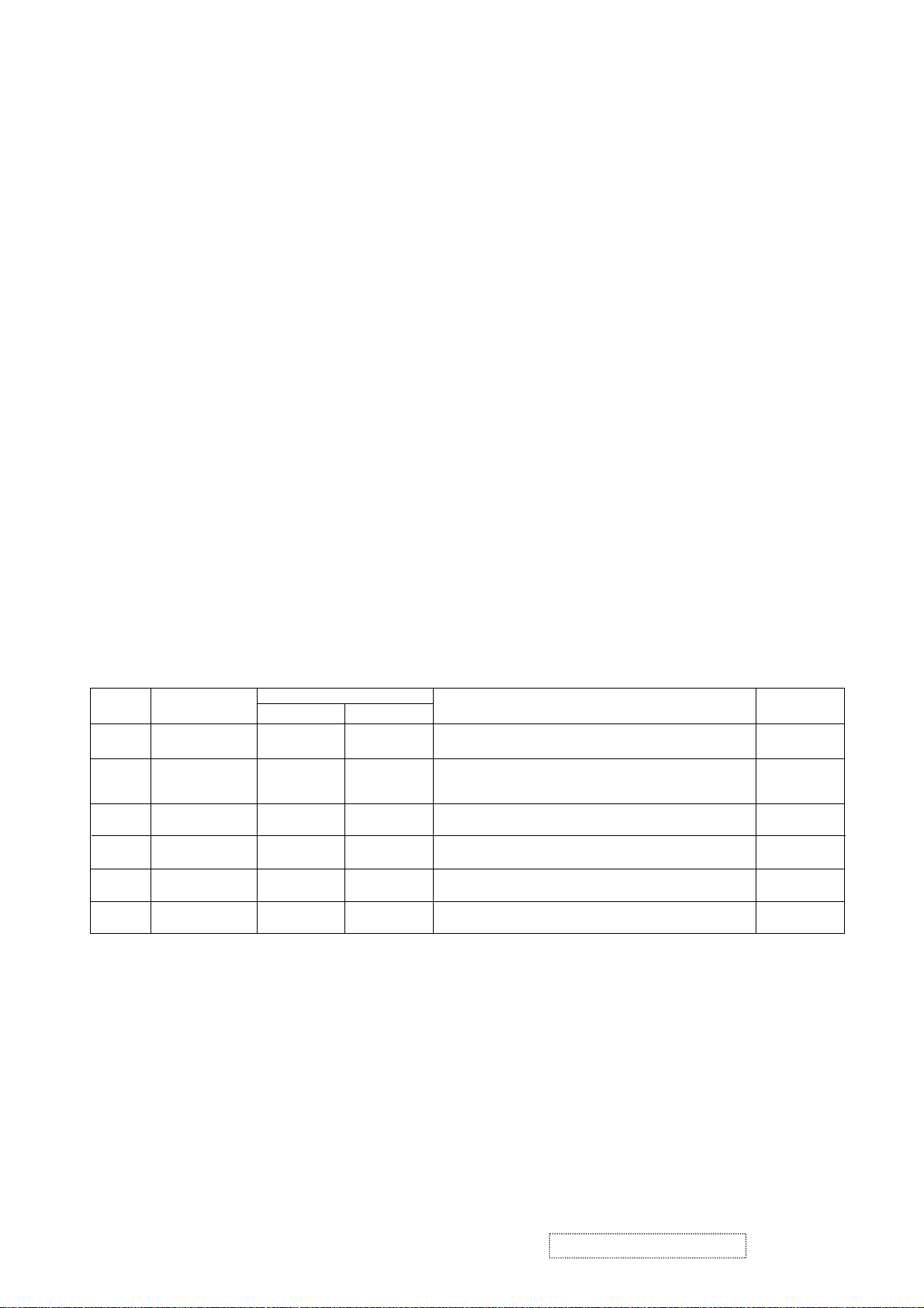
Correct Methods:
Only touch the metal frame of the LCD
panel or the front cover of the monitor. Do
not touch the surface of the polarizer.
Incorrect Methods:
If the surface of the LCD panel is pressed
by fingers, that may cause "MURA."
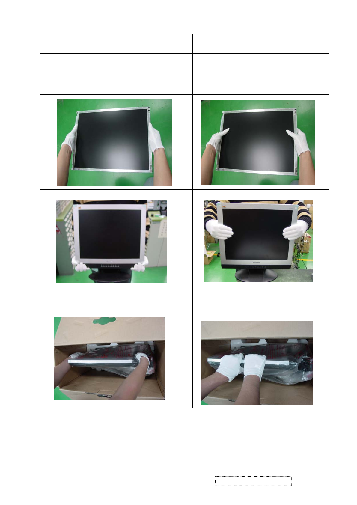
Take out the monitor by grasping the cushions.
If the monitor is removed by grasping the
LCD panel, that may cause "MURA."
ViewSonic Corporation Confidential
3
-
Do Not Copy VG510s/b
Page 7
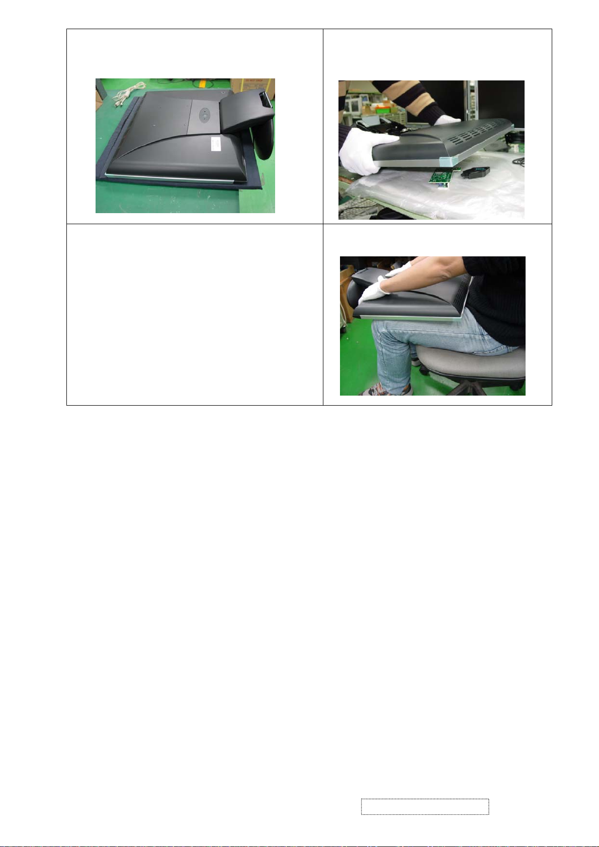
Place the monitor on a clean and soft
foam pad.
If the monitor is placed on foreign objects,
that could scratch the surface of the panel
or cause "MURA."
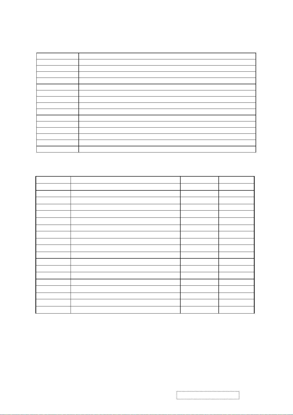
If the panel is placed facedown on the
lap, that may cause "MURA."
ViewSonic Corporation Confidential
4
-
Do Not Copy VG510s/b
Page 8
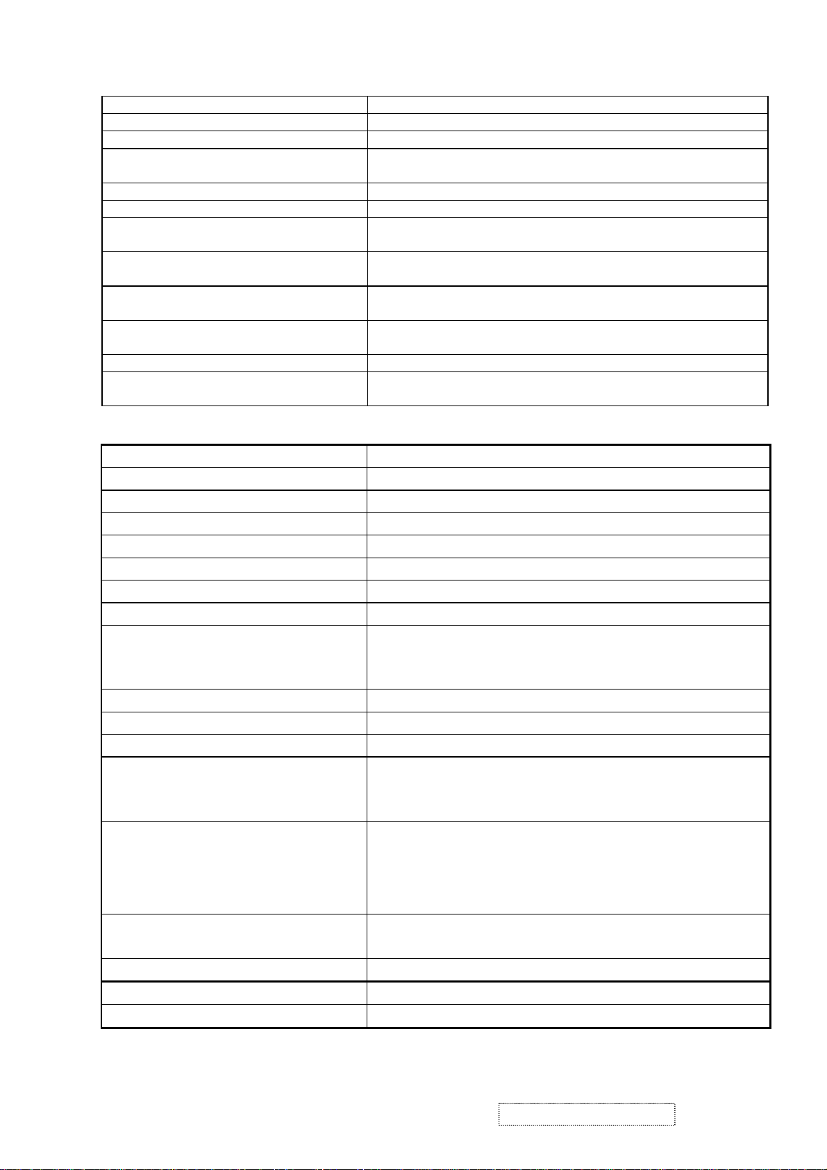
2. Specification
Table : 15 pin D-sub connector pin assignment
Pin Number Pin Function
1 Red video input
2 Green video input
3 Blue video input
4 No Connection
5 Ground
6 Red video ground
7 Green video ground
8 Blue video ground
9 +5V
10 Ground
11 No connection
12 (SDA)
13 Horizontal sync (Composite sync)
14 Vertical sync
15 (SCL)
Timing Table
Item Timing Analog Digital
1 640 x 350 @ 70Hz, 31.5kHz Yes Yes
2 640 x 400 @ 60Hz, 31.5kHz Yes Yes
3 640 x 400 @ 70Hz, 31.5kHz Yes Yes
4 640 x 480 @ 50Hz, 24.7kHz Yes Yes
5 640 x 480 @ 60Hz, 31.5kHz Yes Yes
6 640 x 480 @ 67Hz, 35.0kHz Yes Yes
7 640 x 480 @ 72Hz, 37.9kHz Yes Yes
8 640 x 480 @ 75Hz, 37.5kHz Yes Yes
9 720 x 400 @ 70Hz, 31.5kHz Yes Yes
10 800 x 600 @ 56Hz, 35.1kHz Yes Yes
11 800 x 600 @ 60Hz, 37.9kHz Yes Yes
12 800 x 600 @ 75Hz, 46.9kHz Yes Yes
13 800 x 600 @ 72Hz, 48.1kHz Yes Yes
14 800 x 600 @ 85Hz, 53.7kHz Yes Yes
15 832 x 624 @ 75Hz, 49.7kHz Yes Yes
16 1024 x 768 @ 60Hz, 48.4kHz Yes Yes
17 1024 x 768 @ 70Hz, 56.5kHz Yes Yes
18 1024 x 768 @ 72Hz, 58.1kHz Yes Yes
19 1024 x 768 @ 75Hz, 60.0kHz Yes Yes
User Presets
Number of User Presets (recognized timings) Available: 10 presets total in FIFO configuration
ViewSonic Corporation Confidential
5
-
Do Not Copy VG510s/b
Page 9
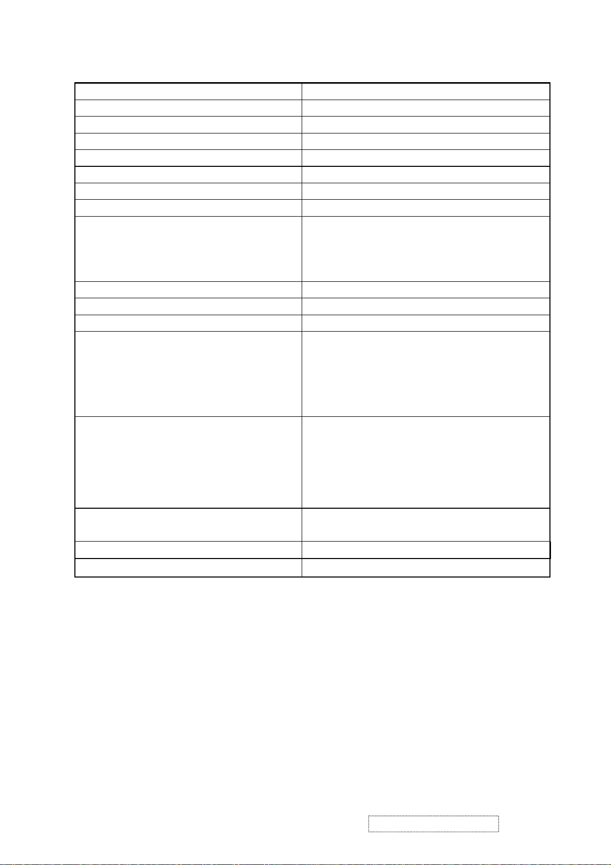
SPEAKER SPECIFICATION
LINE INPUT CONNECTION 3.5 MM STEREO JACK
LINE INPUT SIGNAL 1.0 VRMS
LINE INPUT IMPEDANCE 10 KOHM
MAXIMUM POWER OUTPUT
(ELECTRIC)
SIGNAL TO NOISE RATIO 50 DB
FREQUENCY RESPONSE 380 HZ – 20 KHZ
DISTORTION < 1 % THD (@1KHZ)
VIBRATION THERE SHOULD BE NO AUDIBLE VIBRATION WITH VOLUME
SCREEN IMAGE THERE SHOULD BE NO AFFECT ON THE SCREEN IMAGE
CONNECTOR PC99 REQUIREMENT
AUDIO IN
CABLE TYPE / LENGTH 3.5MM STEREO CABLE / 1.8M LENGTH
AUDIO DPMS SPEAKERS AND MICROPHONE STAY ON WHEN THE
Panel Characteristics
Model number SHARP LQ150X1LGN2C
Type TN TYPE WITH LVDS INTERFACE
Active Size 304.1 (H) X 228.1 (V)
Pixel Arrangement RGB VERTICAL STRIPE
Pixel Pitch 0.297 MM
Glass Treatment ANTI GLARE (HARD COATING 2H)
# of Backlights 2 CCFL EDGE-LIGHT (1 TOP / 1 BOTTOM)
Backlight Life 50,000 HOURS (MIN)
Luminance (Center)– Condition:
CT = 6500K, Contrast = Max, Brightness =
Max
2 W @ < 5% DISTORTION
AT 100% AND TREBLE / BASS AT DEFAULT.
STABILITY UNDER ANY CONDITIONS.
LIME GREEN PANTONE # 577C
REST OF THE MONITOR IS IN POWER SAVING MODE.
260 CD/M2 (TYP AFTER 30 MINUTE WARM UP)
200 CD/M2 (MIN AFTER 30 MINUTE WARM UP)
Brightness Uniformity ≧80% ENTIRE AREA
Contrast Ratio 350:1 (TYP), 250:1 (MIN)
Color Depth 16 MILLION COLORS (8 BIT PANEL)
Viewing Angle (Horizontal) @ CR>10 TYPICAL: 120º (±60º) MINIMUM: 100º (±50º)
@ CR>5 TYPICAL: 160º (±80º) MINIMUM: 140º (±70º)
Viewing Angle (Vertical) @ CR>10 Typical: 100º (U:45º / D:55º) Minimum: 75º (U:30º /
D:45º)
@ CR>5 Typical: 135º (U:55º / D:80º) Minimum: 110º (U:40º /
D:70º)
Response Time
10%-90% @ Ta=25°C
Mercury
16 ms (Tr= 13 ms, Tf = 3 ms) (typ)
25 ms (Tr= 20 ms, Tf = 5 ms) (max)
3.5 mg (Max) per lamp
Panel Defects Please see Panel Quality Specifications.
ViewSonic Corporation Confidential
6
-
Do Not Copy VG510s/b
Page 10
nd
Source Panel
2
Model Number AUO M150XN07 V.1
Type TN TYPE WITH LVDS INTERFACE
Active Size 304.1 (H) X 228.1 (V)
Pixel Arrangement RGB VERTICAL STRIPE
Pixel Pitch 0.297 MM
Glass Treatment ANTI GLARE (HARD COATING 3H)
# of Backlights 2 CCFL EDGE-LIGHT (1 TOP / 1 BOTTOM)
Backlight Life 30,000 HOURS (MIN)
Luminance –
Condition:
250 CD/M2 (TYP AFTER 30 MINUTE WARM UP)
200 CD/M2 (MIN AFTER 30 MINUTE WARM UP)
CT = 6500K, Contrast = Max, Brightness = Max
Brightness Uniformity 80%(TYP) / 75%(MIN) ENTIRE AREA
Contrast Ratio 400:1 (TYP), 300:1 (MIN)
Color Depth 16 MILLION COLORS (6+2 BIT PANEL)
Viewing Angle (Horizontal) @ CR>10
TYPICAL: 120º (±60º)
MINIMUM: 100º (±50º)
@ CR>5
TYPICAL: 150º (±75º)
MINIMUM: 120º (±60º)
Viewing Angle (Vertical) @ CR>10
Typical: 100º (U:40º / D:60º)
Minimum: 80º (U:30º / D:50º)
@ CR>5
Typical: 125º (U:50º / D:75º)
Minimum: 110º (U:45º / D:65º)
Response Time
10%-90% @ Ta=25°C
Mercury
16 ms (Tr= 4 ms, Tf = 12 ms) (typ)
23 ms (Tr= 6 ms, Tf = 17 ms) (max)
3.5 mg (Max) per lamp
Panel Defects Please see Panel Quality Specifications.
ViewSonic Corporation Confidential
7
-
Do Not Copy VG510s/b
Page 11
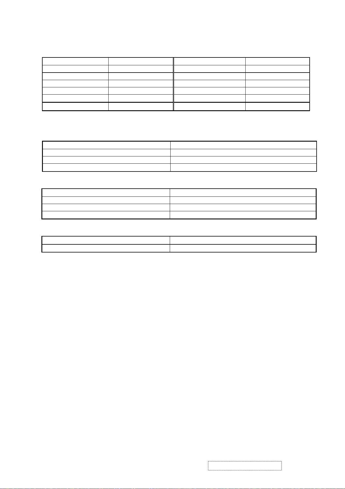
IMAGE PERFORMANCE
Item Defaults Item Defaults
Contrast 75% OSD H. Position 50%
Brightness 100% OSD V. Position 50%
Color Temperature 6500K OSD Time Out 15 Sec
Sharpness 25% OSD Background On
Volume 50% Resolution Notice Enabled
720x400/640x400 720x400
Dimension
Width 346 mm (13.6 inch)
Height 355 mm (14.0 inch)
Depth 156 mm (6.1 inch)
Monitor Weight (w/o 250g AC adapter) 3.4 kg / 7.5 lbs
Dimension (Head Only / Wall Mount)
Width 346 mm (13.6 inch)
Height 305 mm (12.0 inch)
Depth 43 mm (1.7 inch)
Monitor Weight 2.7 kg / 6.0 lbs
Ergonomics
Tilt Up From 0º up to ≧20º
Tilt Down From 0º down to -3º ~ -5 º
ViewSonic Corporation Confidential
8
-
Do Not Copy VG510s/b
Page 12
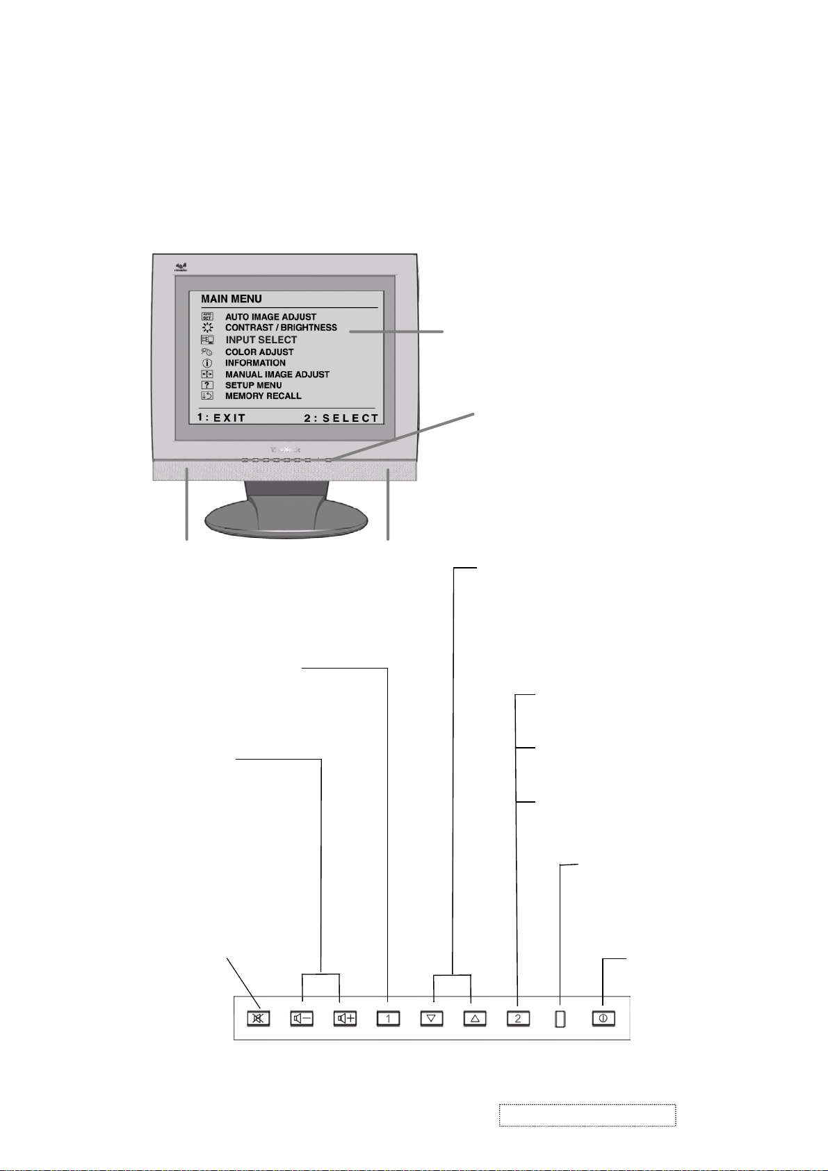
3. Front Panel Function Control Description
Adjusting the Screen Image
Use the buttons on the front control panel to display and adjust the OnView
®
controls which display on the screen. The OnView controls are explained at the
top of the next page.
Main Menu with OnView controls
Front Control Panel shown
below
Speaker Speaker
Scrolls through menu options and
adjusts the displayed control.
Also a shortcut to display the
Contrast adjustment control
screen.
Displays the Main Menu
or exits the control screen
and saves adjustments
Decreases or
increases volume
Audio Mute button
turns the sound off.
Displays the control
screen for the highlighted
control.
Also toggles between two
controls on some
screens.
Also a shortcut to toggle
between analog and
digital connections.
Power light
Green = ON
Orange = Power
Saving
Power
On/Off
ViewSonic Corporation Confidential
9
-
Do Not Copy VG510s/b
Page 13
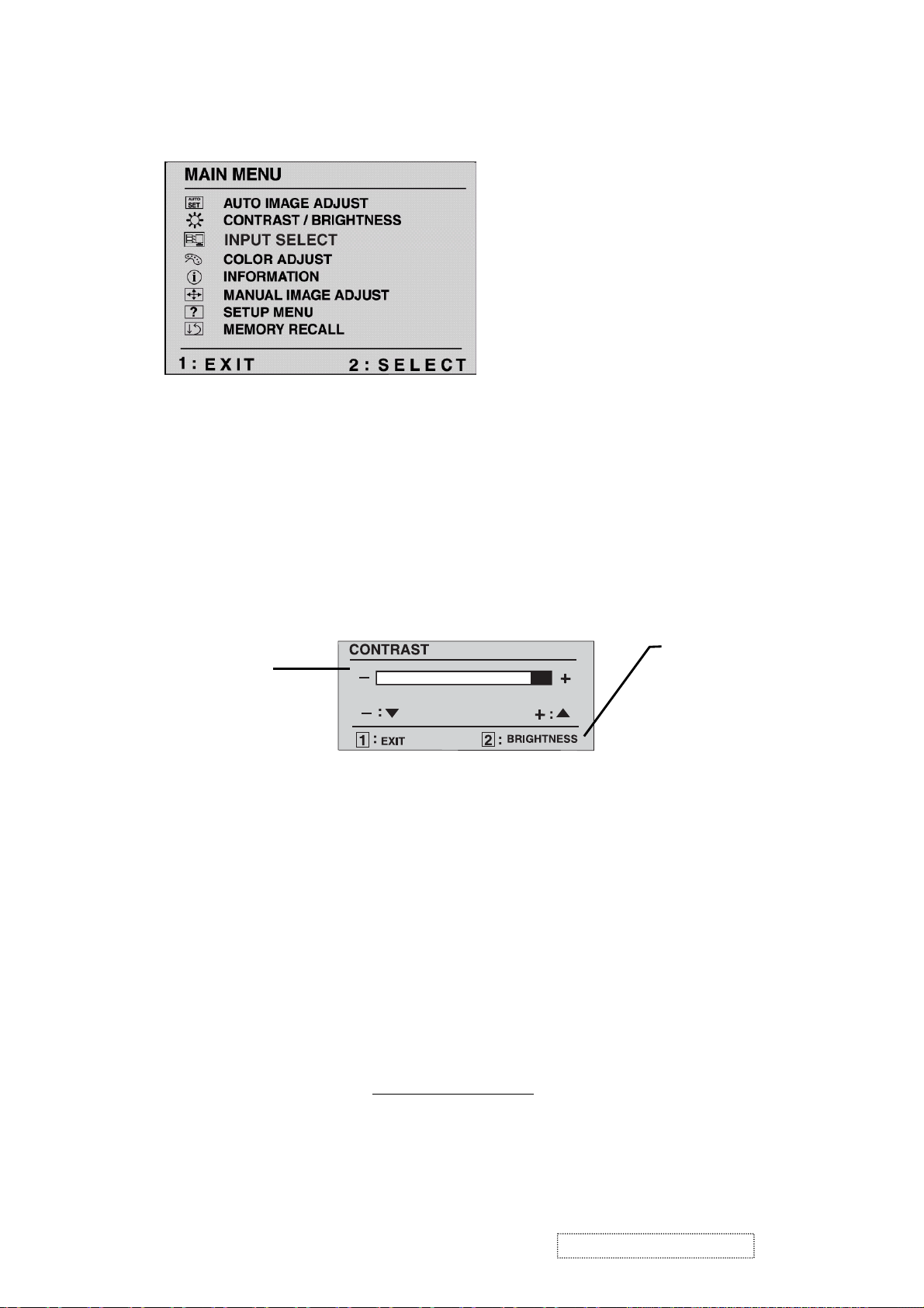
Do the following to adjust the screen image:
1
To display the Main Menu, press button [1].
NOTE: All OnView menus and adjustment screens disappear automatically
after about 30 seconds. This time period is adjustable through the Setup
menu and the OSD timeout control described on page 11.
2
To select a control to be adjusted, press ▲ or ▼ to scroll up or down in
the Main Menu.
3
To select the highlighted control, press button [2]. A control screen appears
like the example shown below.
The line at the bottom
The
arrow decreases,
▲
increases.
4
To adjust the control, press the up ▲ or down ▼ buttons.
5
To save the adjustments and exit the menu, press button [1] twice.
down
▼
up arrow
of the screen shows
the current functions
of buttons 1 and 2:
in this example, either
EXIT or select the
BRIGHTNESS
control.
The following tips may help you optimize your display:
• Adjust your computer's graphic card so that it outputs a video signal 1024 x
768 @ 60 Hz to the LCD display. (Look for instructions on "changing the
refresh rate" in your graphic card's user guide.)
• If necessary, make small adjustments using H POSITION and V POSITION
until the screen image is completely visible
. (The black border around the
edge of the screen should barely touch the illuminated "active area" of the
LCD display.)
ViewSonic Corporation Confidential
10
-
Do Not Copy VG510s/b
Page 14
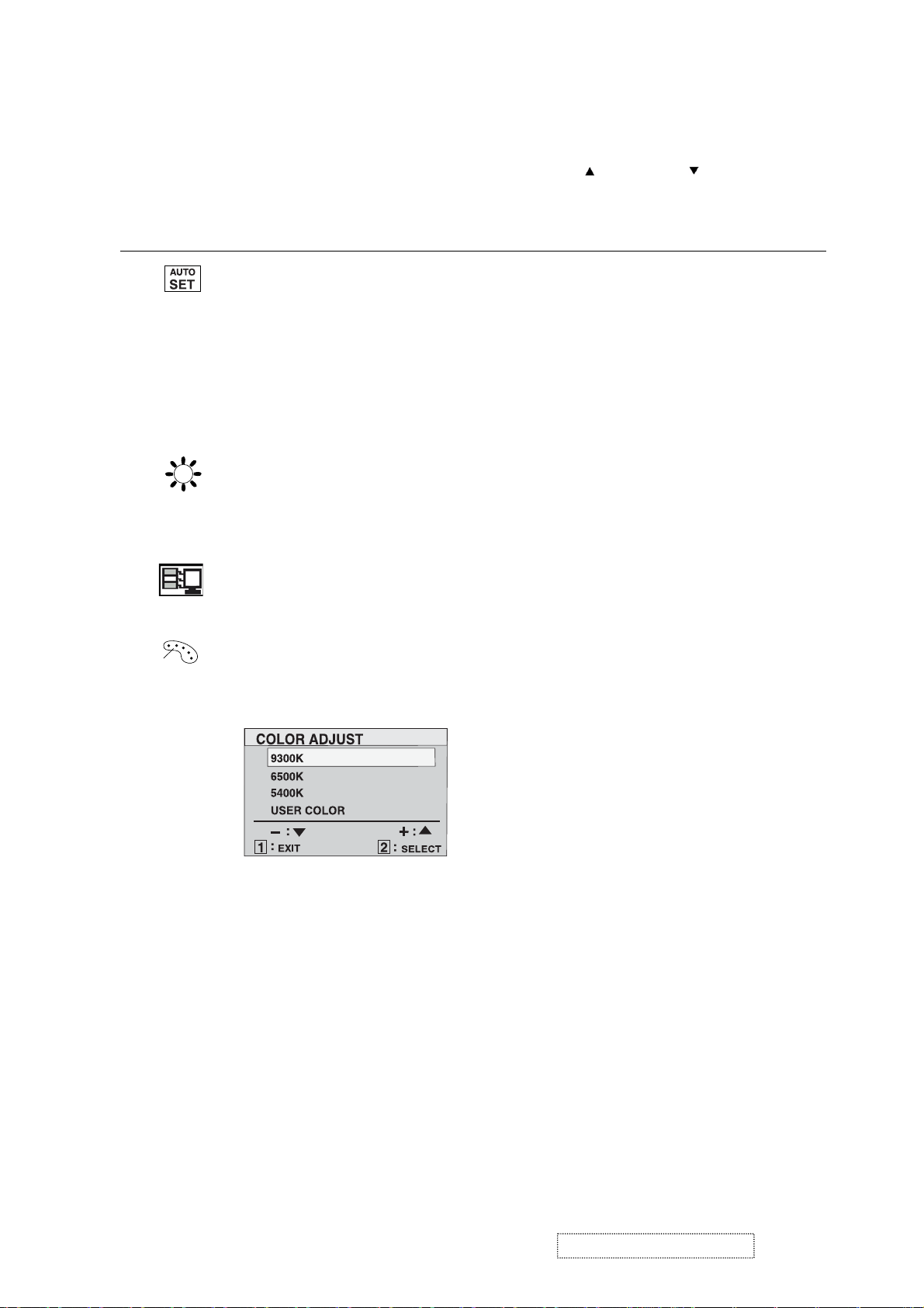
Main Menu Controls
Adjust the menu items shown below by using the up
Control Explanation
Auto Image Adjust
the video signal to eliminate waviness and distortion.
Press the [2] button to obtain a sharper image.
NOTE
: Auto Image Adjust works with most common video
cards. If this function does not work on your LCD display
lower the video refresh rate to 60 Hz and set the resolution to its
pre-set value.
Contrast
adjusts the difference between the image background
(black level) and the foreground (white level).
Brightness
Input Select toggles between analog and digital input signals.
adjusts background black level of the screen image.
automatically sizes, centers, and fine tunes
and down
buttons.
, then
Color Adjust
provides several color options: preset color
temperatures and RGB which allows adjustment of red (R),
green (G), and blue (B). The factory setting for this product is
6500K (6500 Kelvin).
9300K
— Adds blue to the screen image for cooler white (used
in most office settings with fluorescent lighting).
6500K
— Adds red to the screen image for warmer white and
richer red. Default setting.
5400K
User Color
1
2
3
— Adds green to the screen image for a darker color.
— Individual adjustments for red, green, and blue.
To select color (R, G or B) press button [2].
To adjust selected color, press ▲ or ▼.
When you are finished making all color adjustments, press
button [1] twice.
ViewSonic Corporation Confidential
11
-
Do Not Copy VG510s/b
Page 15

Control Explanation
Information
displays the timing mode (video signal input)
coming from the graphics card in your computer. See your
graphic card’s user guide for instructions on changing the
resolution and refresh rate (vertical frequency).
VESA 1024 x 768 @ 60 Hz (recommended) means that the
resolution is 1024 x 768 and the refresh rate is 60 Hertz.
Manual Image Adjust
The Manual Image Adjust controls are explained below:
H. Size (Horizontal Size) adjusts the width of the screen image.
NOTE: Vertical size is automatic with your LCD display.
H./V. Position adjusts horizontal and vertical position of the
screen image. You can toggle between Horizontal and Vertical
by pressing button [2]. Horizontal moves the screen image to
the left or to the right. Vertical moves the screen image up and
down.
Fine Tune
sharpens focus by aligning the illuminated text and/
or graphic characters.
NOTE: Try the
Fine Tune
Sharpness
control.
adjusts the clarity and focus of the screen image.
Auto Image Adjust
(see page 9) before using the
ViewSonic Corporation Confidential
12
-
Do Not Copy VG510s/b
Page 16
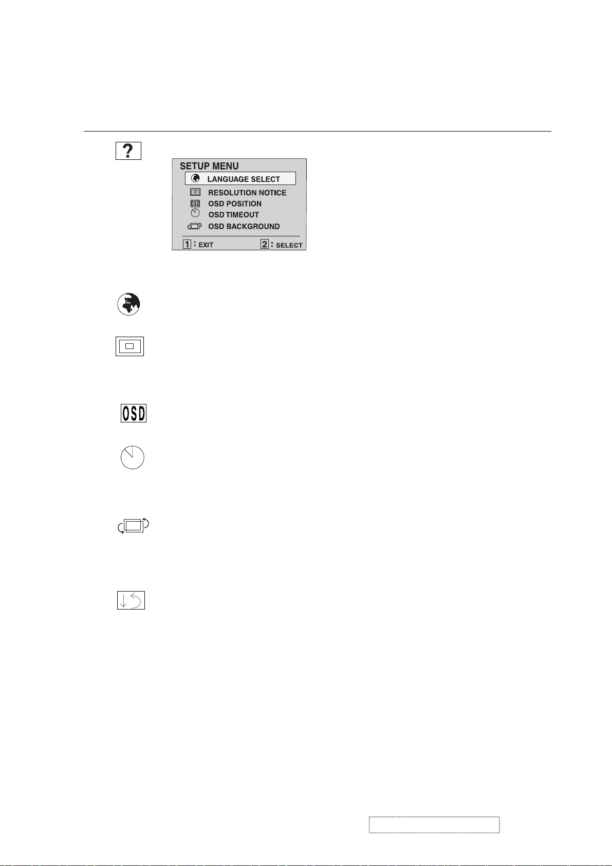
Control Explanation
Setup Menu
displays the menu shown below:
The Setup Menu controls are explained below:
Language Select allows you to choose the language used in the
menus and control screens.
Resolution Notice advises the optimal resolution to use. After
selecting Resolution Notice, a sub menu appears asking if you
want to Disable or Enable the notice. If you want the Resolution
Notice to appear on-screen, select Enable.
OSD Position
allows you to move the on-screen display
menus and control screens.
OSD Timeout
sets the length of time an on-screen display
screen is displayed. For example, with a “15 second” setting, if
a control is not pushed within 15 seconds, the display screen
disappears.
OSD Background
allows you to turn the On-Screen display
background on or off. This means that while making adjustments
from the OSD control screens you can also view open software
applications, or the Windows desktop.
Memory Recall
returns adjustments to the original factory
settings if the display is operating in a factory Preset Timing
Mode listed in this user guide.
Exception: This control does not effect changes made with the
User Color control.
ViewSonic Corporation Confidential
13
-
Do Not Copy VG510s/b
Page 17
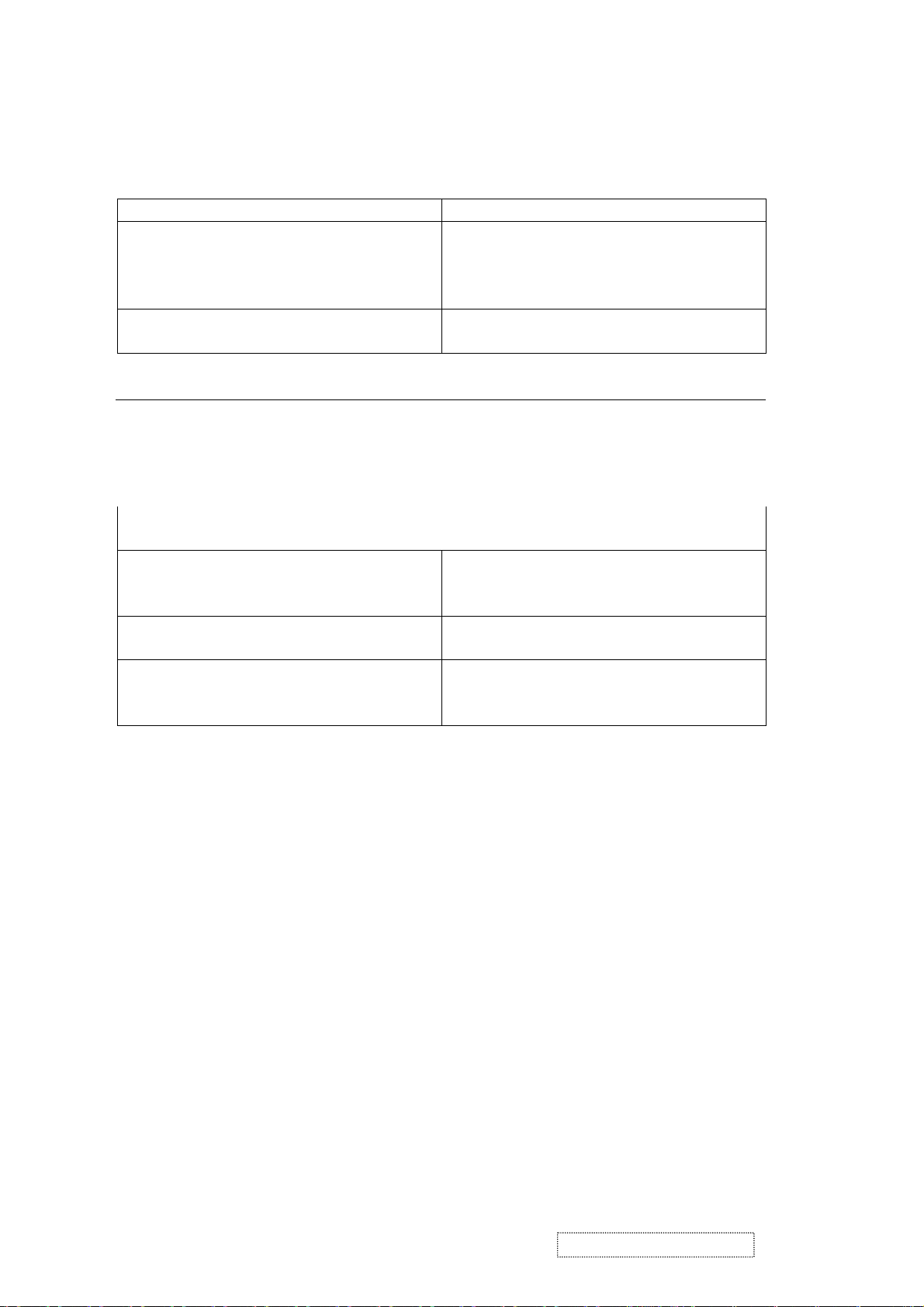
Hot Keys for Feature Controls
Buttons: Functions:
[Up] + [Down] arrows Reset Contrast or Brightness while in the
Contrast or Brightness adjustment screen,
or reset both Contrast and Brightness
when the OSD is not active.
[Volume-] + [Volume+] Reset volume to 50% while in the volume
adjustment screen, or when the OSD is not active.
[1] + [2] Toggle between 720x400 and 640x400 display
modes when the input signal is 720x400 or 640x400.
[1] + [Up] + [Down] Automatically adjust the White Balance to suit the
current video signal. To obtain the best adjustment,
the input signal should be set to a pure black and
white pattern at 640x480 resolution and 60 Hz
refresh rate.
[1] + [Down] (hold for 10 seconds) Power Lock (Unlock). When Power Lock is
enabled, the monitor cannot be turned off.
[1] + [Up] (hold for 10 seconds) OSD Lock (Unlock). When OSD Lock is enabled,
all settings are fixed (including "Volume" and
"Mute").
[Up] + [Power On] with signal (hold for 3
seconds)
[2] + [Power On] without signal (hold for
3 seconds)
All Mode Reset. Erase all user settings and
restore the factory defaults.
Burn In Mode. After entering Burn In Mode,
press the [1] button to display monitor
information.
ViewSonic Corporation Confidential
14
-
Do Not Copy VG510s/b
Page 18

4. Circuit Description
A. DC-DC CONVERTER
This block converts the 12V input voltage to 5V for panel use and 3.3V for controller use.
It consists of a PWM IC (AP1501), flywheel Diode (D1), buck choke (L2), and capacitor (C70,71).
The AP1501 is a PWM generator working at 150Khz.
Self protection features include a two-stage frequency reducing current limit for the output
switch and an over temperature shutdown for complete protection under fault conditions.
B. A/D converter
The MST9111 is a highly integrated TFT LCD controller chip with the latest MST advanced image
processing technology and an integrated ADC/PLL. The MST9111 has an advanced programmable
non-linear parametric cubic based scaling engine with proprietary sharpness adjustment and text
enhancement. The MST9111 supports both analog and digital interfaced inputs with an internal ADC/PLL.
The MST9111 robustly handles a wide variety of TFT LCD panels and provides strong support of
standard or non-standard input timings.
. Integrated high speed triple 8-bit ADC/PLL support up to 85MHz for XGA-75Hz
. Advanced image processing with proprietary non-linear parametric cubic based scaling engine
. Supports dual interface with an integrated ADC/PLL
. Robust auto configuration for input mode detection and
clock frequency and phase recovery for standard or nonstandard input timing
. Supports video processing with on-chip 2D de-interlacing and color space conversion
. Supports programmable Gamma Correction
. GPIO pins for flexible system design
D. MCU:
The MTV512 micro-controller is an 8051 CPU core embedded device specially tailored to LCD monitor
applications. It includes an 8051 CPU core, 1024-byte SRAM, 14 built-in PWM DACs, VESA DDC
interface, 4 channel 6-bit A/D converter, a 64 K-byte internal program Flash-ROM.
ViewSonic Corporation Confidential
15
-
Do Not Copy VG510s/b
Page 19

5. Adjustment Procedure
5-1 Product:
15” LCD Monitor
5-2 Test Equipment:
5-3 Test Condition
Before function test and alignment, each LCD Monitor should be run-in and warmed up for at least
30 minutes under the following conditions:
(a) At room temperature,
(b) With full white screen, RGB, and black
(c) With cycled display modes,
640x480 (H=43.27 kHz, V=85Hz)
800x600 (H=53.7 kHz, V=85Hz)
1024x768 (H=68.67 kHz, V=85Hz)
5-4 Test Display Modes & Pattern
5-4-1 Compatible Modes
1. 640 x 350 @ 70Hz, 31.5kHz
2. 640 x 480 @ 60Hz, 31.5kHz
3. 640 x 480 @ 67Hz, 35.0kHz
4. 640 x 480 @ 75Hz, 37.5kHz
5. 640 x 480 @ 72Hz, 37.9kHz
6. 640 x 480 @ 85Hz, 43.27kHz
7. 720 x 400 @ 70Hz, 31.5kHz
8. 800 x 600 @ 56Hz, 35.1kHz
9. 800 x 600 @ 60Hz, 37.9kHz
10. 800 x 600 @ 75Hz, 46.9kHz
11. 800 x 600 @ 72Hz, 48.1kHz
12. 800 x 600 @ 85Hz, 53.7kHz
13. 832 x 624 @ 75Hz, 49.7kHz
14. 1024 x 768 @ 60Hz, 48.4kHz
15. 1024 x 768 @ 70Hz, 56.5kHz
16. 1024 x 768 @ 72Hz, 58.1kHz
17. 1024 x 768 @ 75Hz, 60.0kHz
18. 1024 x 768 @ 85Hz, 68.67kHz
5-4-2 Auto Image Adjust
Please select and activate the "Auto Image Adjust" function on the Main Menu to verify that it functions
properly. The "Auto Image Adjust" function is intended to provide satisfactory image quality by
means of the built-in ASIC. For optimum image quality, the user must adjust each setting manually.
5-4-3 Firmware
Test Pattern: Burn in Mode (Refer to Chapter III-3. Hot Keys for Feature Controls)
- Verify that the firmware version is the latest.
5-4-4 DDC
Test Pattern: EDID program
- Verify that the test program passes.
5-4-5 Fine Tune and Sharpness
Test Signal: 1024 x 768 @ 60.0kHz
Test Pattern: Line Moiré Pattern
- Verify whether the focus performs well, or whether the image has pixel-related noise. Eliminate the visible bars.
- If necessary, adjust with the following steps:
(a) Select and activate the "Fine Tune" function on the "Manual Image Adjust" menu to eliminate the visible bars.
(b) Select and enter the "Sharpness" function to adjust the clarity and focus of the screen image.
Color Video Signal & Pattern (or PC with SXGA resolution)
ViewSonic Corporation Confidential
16
-
Do Not Copy VG510s/b
Page 20

5-4-6 White Balance
Test Signal: 640*480@60Hz
Test Pattern: Full White and Black Pattern
5-4-7 R, G, B, Colors Contrast
Test Signal: 1024 x 768 @ 60.0kHz
Test Pattern: R, G, B, Color Intensities Pattern and 16 Gray Scale Pattern
- Verify that each color is normal and distinct.
- If not, please return the unit to repair area.
5-4-8 Screen Uniformity and Flicker
Test Signal: 1024 x 768 @ 60.0kHz
Test Pattern: Full White Pattern
- Verify that screen uniformity and flicker are normal.
5-4-9 Dead Pixel and Line
Test Signal: 1024 x 768 @ 60.0kHz
Test Pattern: Dark and White Screen Pattern
- Check for the presence of dead pixels on the LCD panel with shadow gauge and filter film.
- The total number and spacing of dead pixels should be compliant with the spec.
5-4-10 Mura
Test Pattern: White, RGB, Black, & Grey
Test Tool: 10% ND Filter
- Verify that MURA, if any, can pass 10% ND Filter.
5-4-11 Audio
Test Signal: Voice signal (optional, depends on model)
Test Pattern: Any
- Make sure there is audio output.
- Make sure that the audio function (volume %) functions without noise or resonance.
≦80
- Make sure that the output of the right and left speakers is balanced.
5-4-12 Test Under Secondary Display Modes
Test Signal:
Analog: 640x350@70Hz; 640x480@60/67/72/75/85Hz;
720x400@70Hz; 800x600@56/60/72/75/85Hz;
832x624@75Hz, 1024x768@60/70/72/75Hz;
Digital: 640x350@70Hz; 640x480@60/72/75/85Hz;
720x400@70Hz; 800x600@56/60/72/75/85Hz;
1024*768@60/70/72/75Hz
- Normally when the primary mode (1280x1024@60Hz) is well adjusted and compliant
with the specification, the secondary display modes will most likely also be compliant with the spec.
However it is still necessary to verify with the general test pattern that each secondary display mode
is compliant with the specification.
5-4-13 All Modes Reset
After the final QC step, it is necessary to erase all saved changes and restore the factory defaults.
Please execute the "All Mode Reset" function again.
5-4-14 Power off Monitor
Turn off the monitor by pressing the "Power" button.
ViewSonic Corporation Confidential
17
-
Do Not Copy VG510s/b
Page 21

5-5 Firmware Upgrade Procedure
5-5-1 Equipment Needed
- VG510 Monitor
- Fixture for Firmware Upgrade
- Power Adapter (P/N: 47.58201.001) *1 for Fixture
- VGA Cable (P/N: 42.59901.003) *1(Pin 4, 11 should be connected to GND)
- PC (Personal Computer)
- LPT Cable (P/N: 42.59906.001) *1
- Firmware Upgrade Program
- One additional monitor for checking the program execution PC
Fixture
Printer Port
VG510
5-5-2 EDID Procedure
DDC User’s manual
1. Hardware installation
A. A. The EDID cable is designed to connect two different terminal types:
one end is a male 25 pin printer connector and the other end is a male 15 pin D-sub connecter.
B. Connect the EDID cable from the PC Printer port to the monitor D-sub connector.
C. Make sure the monitor is running under power saving mode and keep it in power saving mode
during the DDC process.
EDID-Kit
Cable
25 Pin Printer
Connector
(to PC Printer Port)
ViewSonic Corporation Confidential
18
15 Pin VGA
(D-Sub) Connector
(to Monitor)
-
Do Not Copy VG510s/b
Page 22

5-5-3 Programming procedure
A. Obtain the DDC files. Normally, these are provided as an EDID zip file for the new model; unzip the file.
B. The following files are required for the DDC program: (VG510 is an example)
1. DPS.EXE
2. VG510.BAT
3. VG510.DDC
4. VG510.CFG
5. VG510.DPS
C.Execute VG900.BAT (for VG510 monitor only) on the programming PC. The screen will display the image
shown in Fig-DDC1 below.
Fig-DDC1
Refer to Fig-DDC1; change the default settings if desired.
Press 1: To edit the year, move the cursor to the position beside "Edit Year" and key in the desired
value, then press enter to exit and return. The value entered must be four digits.
Press 2: To edit the week, move the cursor to the position beside "Edit Week" and key in the desired
value, then press enter to exit and return. The value entered must be within the range 1 ~ 53.
Press 3: To edit the serial number, move the cursor to the position beside "Edit S/N" and key in the
desired value, then press enter to exit and return. The value entered must be within 0 ~ 99999,
5 digits max.
ViewSonic Corporation Confidential
19
-
Do Not Copy VG510s/b
Page 23

D. Press the "ESC" or "Enter" key to return to the main menu. The screen will display the image shown
in Fig-DDC2 and the updated serial number, if applicable, will be shown on the right corner of the screen.
Fig-DDC2
When the screen displays the image shown in Fig-DDC2, the "Week" value may be changed by
pressing the "*" key and the "S/N" value may be changed by pressing the "-" key.
Press 3 "DDC Write/Check Data": Select this command to begin programming the new EDID data into the
monitor. When programming is complete, all DDC data will be displayed on the screen. When the screen
displays the image shown in Fig-DDC3 below, the DDC process is finished.
Display updated serial
number.
Fig-DDC3
ViewSonic Corporation Confidential
20
-
Do Not Copy VG510s/b
Page 24

The message "E2PROM Acknowledge Not Echo!" will appear on the screen if the programming PC
detects an error. If this error message appears, please re-check the cable connection and return to the first step.
Please refer to the Viewsonic EDID data format that is printed on the ID label.
PPPYYWWxxxxx
PPP = Viewsonic Regional Product ID Code, EX. VE500 is “910”, VE700 is “A10” and VG900 is “A1C ”.
YY= 2 digits of Manufacturing year. (range 1996-2015).
WW = 2 digits of Manufacturing week (range 01-54).
xxxxx = 5 digits of Sequence number. (range 00001-99999).
ViewSonic Corporation Confidential
21
-
Do Not Copy VG510s/b
Page 25

5-6 ISP procedure
Connecting the ISP Kit:
Using an RS-232 cable, connect the ISP board (P3) to the PC's COM port.
Using a VGA cable, connect the ISP board (CN702) to the monitor (destination).
Connect the +12V power supply to the ISP board (J701).
ViewSonic Corporation Confidential
22
-
Do Not Copy VG510s/b
Page 26

Monitor ISP Mode setting
Press the ? , 2, and Power buttons simultaneously, then plug in the DC power adapter. The OSD
message "Enter ISP" will appear on the monitor screen.
Setting of ISP program on PC
1. Setup the MYSON ISP program.
2. Execute the ISP program; the window shown below appears.
3. Select "MTV512M64" MCU type.
4. Set CPU to 5 MHz.
ViewSonic Corporation Confidential
23
-
Do Not Copy VG510s/b
Page 27

5. Click “Load MCU file
” and then find the updated firmware code.
6. Click "Create Security File" to proceed to the next window.
7. Set "Command No" to 4.
8. Enter the following values: ISP Slave Add = 94; Slave B Add = 94; Command 1 = a;
Command 2 = ca; Command 3 = 53.
9. Click "OK" to start ISP execution and load the firmware into the monitor.
ViewSonic Corporation Confidential
24
-
Do Not Copy VG510s/b
Page 28

10. Firmware update is complete when the display returns to the window shown below.
ViewSonic Corporation Confidential
25
-
Do Not Copy VG510s/b
Page 29

No No
es No
Start
6. Troubleshooting Flow Chart
Does Display
Show an Image?
Is Backlight
Functional?
Has Power
CKT Failed?
Y
Check OSD
& key function
Yes
Yes
Is Problem in
LCD Cable,
Connector or LCD Panel?
Does Adjusting Display
Resolution Solve Problem?
No
No
Check I/F Board
ViewSonic Corporation Confidential
26
-
Do Not Copy VG510s/b
Page 30

Power 12V-In J1
12V-in
LVDS Signal Output
To Panel J7
LVDS Signal
I/F bard power
Check Start
Check
+3.3V(U2)
+5.0V(U1)
+2.5V(U4)
MCU VC
Power _In
RTD2513 & MCU
Check Start
(no display)
Yes
No
Check U10
Output LVDS Signal
(CON7 Odd and
Even Data
No
)
Yes
End
No
Check 12V input
Power (J1)
Yes
Check U7:
I2C Signal( IICS DA,IICS CL)、
Clock(Y1_24MHz)、Reset Pin(RST)
Host Interface U10:
(RTD_SDO,RTD_SCLK,RTD_SCSB)、
VGA Iinput Signal(R、G、B、H/V_Sync)
DVI-D Input (Data 0~2 & Clk)
Power CKT
Yes
End
RTD2513&MCU CKT
R G
B
DATA 0~2
& CLK
I/F Board DPWBN5643T8----
VGA Input
CN1
DVI-D Input
CON3
ViewSonic Corporation Confidential
27
-
Do Not Copy VG510s/b
Page 31

OSD no response
Check SW
oard Sw1~Sw8
B
Check I/F Board
& Panel
Too dim
The brightness is
different between
upper side and
lower side
Partial picture
without color
Vertical, horizontal
not synchronized
Vertical lines appear
in various colors
RGB Signal error
Check OSD
adjustment
Check inverter
& backlight
Check I/F Board
& Panel
Check Panel
Check SW Board
J1 & Inverter
&I/F Board
Even / odd vertical
lines wrong color
ViewSonic Corporation Confidential
28
-
Do Not Copy VG510s/b
Page 32

7. Recommended Spare Parts List
RECOMMENDED SPARE PARTS LIST (VG510b-1 with AU Panel)
ViewSonic Model Number: VLCDS27955-2W
Rev: 1c
Item ECR/ECN ViewSonic P/N Ref. P/N Location Q'ty
Accessories:
1 AC ADAPTOR (HJC 12V/3.3A) A-00000352 RUNTP5630T8---- AC ADAPTOR (HJC 12V/3.3A) 1
2 POWER CORD A-PC-0106-0180 QACC-1126D8D--- POWER CORD 1
PC Board Assembly:
3 I/F BOARD ASS'Y B-00000349 DPWBN5643T8---- I/F BOARD ASS'Y 1
4 INVERTER BOARD B-00000345 RUNTP5561T8---A INVERTER BOARD 1
5 OSD-SW BOARD ASS'Y B-CB-0206-0179 DPWBN5548T8---- OSD-SW BOARD ASS'Y 1
Cabinets:
6 BACK COVER M-MS-0808-9114 GCOVD2551D8F--A BACK COVER 1
7 BASE PL-PS-0715-0977 GSTN-2916D8F--A BASE 1
8 BASE FRONT COVER M-CV-0830-2498 GCOVD2552D8F--A BASE FRONT COVER 1
9 BASE-BACK COVER M-CV-0830-2499 GCOVD2553D8F--A BASE-BACK COVER 1
10 CAB-A M-MS-0808-9113 GCABA2331D8FT1C CAB-A 1
11 CAB-B C-BC-0302-0560 GCABB1852D8F--A CAB-B 1
Cables:
12 AUDIO CABLE A-AU-0120-0034 QCODK0030D8D--A AUDIO CABLE 1
13 FFC CABLE (20 PIN) CB-00001055 QCODP1207T8---- FFC CABLE (20 PIN) 1
14 INVERTER WIRE CB-00001056 QCNWP0905T8019- INVERTER WIRE 1
15 OSD-SW WIRE CB-00001057 QCNWS090B-8018- OSD-SW WIRE 1
16 SIGNAL CABLE A-VC-0101-0271 QCODS1584D8D--- SIGNAL CABLE 1
17 SPEAKER WIRE M-WR-0828-6015 QCNWS0904-8038- AUDIO WIRE 1
Documentation:
18 CD Wizard (CD-ROM) A-CD-VG510B DDSKC0043D8---- INF FILE DEVICE 1
19 ID LABEL M-LB-0830-0696 PISLV0237D8---A ID LABEL 1
20 Quick Start Guide A-UG-0107-0533 TINSE3073D8---- MANUAL 1
Electronic
21
Components:
22
23 AUO PANEL (15") E-00000344 VVLM150XN07---- AUO PANEL (15" XN07) 1
24 D-SUB CONNECTOR E-00001059 QCNCD1173T8---- CN1 1
25 DVI CONNECTOR E-00001060 QCNCD1161T8---- CON3 1
26
27
28 INVERTER WIRE CB-00001056 QCNWP0905T8019- INVERTER WIRE 1
29
30 OSCILLATOR (24.000MHZ) E-00001062 RCRSL1170T8---- Y1.(24.000 MHZ) 1
31 OSCILLATOR (24.576MHZ) E-00001063 RCRSL1252T8---- Y2.(24.576 MHZ), 1
32 OSD-SW WIRE CB-00001057 QCNWS090B-8018- OSD-SW WIRE 1
33
34 SPEAKER E-SK-0412-0085 RSPKCL032D88FG- SPEAKER 1
35 SPEAKER WIRE M-WR-0828-6015 QCNWS0904-8038- AUDIO WIRE 1
Hardware:
36 BASE METAL M-BK-0805-0032 LANGF2132D8---- BASE METAL 1
37 D-SUB METAL HW-00000351 LANGF2133D8---A D-SUB METAL 1
38 HINGE ASSEMBLY M-MS-0808-9112 MHNGM0046D8---- HINGE ASSEMBLY 1
39 INVERTER SHIELD HW-00001065 PSLDM6568D8---A INVERTER SHIELD 1
40 KENSINGTON BRACKET M-BK-0805-0012 LANGF2063D8---A KENSINGTON BRACKET 1
41 MAIN METAL HW-00000346 LANGF2130D8---B MAIN METAL 1
42 VESA METAL M-BK-0805-0033 LANGF2131D8---- VESA METAL 1
Miscellaneous:
43 BACK COVER LOGO M-MS-0808-9116 HBDGE1391D8---- VS LOGO ON BACK COVER 1
44 BOSS FOR D-SUB AND DVI M-00001066 LBOSM1092D8---- BOSS FOR D-SUB AND DVI 4
45 CUSHION FOR CAB-B M-MS-0808-9385 PCUSG1638D8---- CUSHION FOR CAB-B 3
46 CUSHION-A M-MS-0808-9383 PCUSG1633D8---- CUSHION-A 2
47 CUSHION-B M-MS-0808-9384 PCUSG1632D8---- CUSHION-B 1
48 CUSHION-C M-MS-0808-9382 PCUSG1634D8---- CUSHION-C 1
49 VE-LOGO M-MS-0808-9123 HBDGE1388D8---- VE-LOGO 1
50 VESA GUM M-MS-0808-9117 PGUM-1124D8---- VESA GUM 4
51 VIEWSONIC TEXT LOGO M-MS-0808-9118 HBDGE1389D8---- VIEWSONIC TEXT LOGO 1
Packing Material:
52 CARTON P-BX-0601-0922 SPAKC3630D8---C CARTON 1
53 PACKING M-MS-0808-9120 SPAKA6557D8---- PACKING 1
Plastics:
54 KNOB PL-NB-0707-1072 JKNBP2358D8F--- KNOB 1
55 LENS M-MS-0808-9115 HDECP1987D8F--- LENS 1
56 LOGO PLATE (BIRDS LOGO) M-MS-0808-9119 HBDGE1390D8---- LOGO PLATE (BIRDS LOGO) 1
Description
20 PIN CONNECTOR
44PIN PLCC IC SOCKET
EEPROM
FUSE 4A
MCU
SCALER REALTEK
E-00001058 QCNCP2140T8---- J7 (20 PIN PLUG) 1
M-MS-0808-8003 QSOCI1642T844-- U7 (44 PIN IC SOCKET) 1
E-IC-0401-2584 VSI24C16------E-FS-0410-0099 QFS-Z402F-81UAA
E-00001061 VSIMTV512MV---S
E-00001064 VSIRTD2513----D U10 (SCALER IC) 1
U8
F1
U7
1
1
1
ViewSonic Corporation Confidential
29
-
Do Not Copy VG510s/b
Page 33

RECOMMENDED SPARE PARTS LIST (VG510b-1 with Sharp Panel)
ViewSonic Model Number: VLCDS27955-2W
Rev: 1c
Item ECR/ECN ViewSonic P/N Ref. P/N Location Q'ty
Accessories:
1 AC ADAPTOR (HJC 12V/3.3A) A-00000352 RUNTP5630T8---- AC ADAPTOR (HJC 12V/3.3A) 1
2 POWER CORD A-PC-0106-0180 QACC-1126D8D--- POWER CORD 1
PC Board Assembly:
3 I/F BOARD ASS'Y B-00000349 DPWBN5643T8---- I/F BOARD ASS'Y 1
4 INVERTER BOARD B-SB-0221-0588 RUNTP5475T8---F INVERTER BOARD 1
5 OSD-SW BOARD ASS'Y B-CB-0206-0179 DPWBN5548T8---- OSD-SW BOARD ASS'Y 1
Cabinets:
6 BACK COVER M-MS-0808-9114 GCOVD2551D8F--A BACK COVER 1
7 BASE PL-PS-0715-0977 GSTN-2916D8F--A BASE 1
8 BASE FRONT COVER M-CV-0830-2498 GCOVD2552D8F--A BASE FRONT COVER 1
9 BASE-BACK COVER M-CV-0830-2499 GCOVD2553D8F--A BASE-BACK COVER 1
10 CAB-A M-MS-0808-9113 GCABA2331D8FT1C CAB-A 1
11 CAB-B C-BC-0302-0560 GCABB1852D8F--A CAB-B 1
Cables:
12 AUDIO CABLE A-AU-0120-0034 QCODK0030D8D--A AUDIO CABLE 1
13 FFC CABLE (20 PIN) CB-00001055 QCODP1207T8---- FFC CABLE (20 PIN) 1
14 INVERTER WIRE CB-00001056 QCNWP0905T8019- INVERTER WIRE 1
15 OSD-SW WIRE CB-00001057 QCNWS090B-8018- OSD-SW WIRE 1
16 SIGNAL CABLE A-VC-0101-0271 QCODS1584D8D--- SIGNAL CABLE 1
17 SPEAKER WIRE M-WR-0828-6015 QCNWS0904-8038- AUDIO WIRE 1
Documentation:
18 CD Wizard (CD-ROM) A-CD-VG510B DDSKC0043D8---- INF FILE DEVICE 1
19 ID LABEL M-LB-0830-0696 PISLV0237D8---- ID LABEL 1
20 Quick Start Guide A-UG-0107-0533 TINSE3073D8---- MANUAL 1
Electronic
21
Components:
22
23 D-SUB CONNECTOR E-00001059 QCNCD1173T8---- CN1 1
24 DVI CONNECTOR E-00001060 QCNCD1161T8---- CON3 1
25
26
27
28 OSCILLATOR (24.000MHZ) E-00001062 RCRSL1170T8---- Y1.(24.000 MHZ) 1
29 OSCILLATOR (24.576MHZ) E-00001063 RCRSL1252T8---- Y2.(24.576 MHZ), 1
30
31 Sharp PANEL (15") M-LCD-0826-0180 VVLLQ150X1LGN2C Sharp PANEL (15" LANG2C) 1
32 SPEAKER E-SK-0412-0085 RSPKCL032D88FG- SPEAKER 1
Hardware:
33 BASE METAL M-BK-0805-0032 LANGF2132D8---- BASE METAL 1
34 D-SUB METAL M-BK-0805-0034 LANGF2133D8---- D-SUB METAL 1
35 HINGE ASSEMBLY M-MS-0808-9112 MHNGM0046D8---- HINGE ASSEMBLY 1
36 INVERTER SHIELD HW-00001065 PSLDM6568D8---A INVERTER SHIELD 1
37 KENSINGTON BRACKET M-BK-0805-0012 LANGF2063D8---A KENSINGTON BRACKET 1
38 MAIN METAL HW-00000346 LANGF2130D8---B MAIN METAL 1
39 VESA METAL M-BK-0805-0033 LANGF2131D8---- VESA METAL 1
Miscellaneous:
40 BACK COVER LOGO M-MS-0808-9116 HBDGE1391D8---- VS LOGO ON BACK COVER 1
41 BOSS FOR D-SUB AND DVI M-00001066 LBOSM1092D8---- BOSS FOR D-SUB AND DVI 4
42 CUSHION FOR CAB-B M-MS-0808-9385 PCUSG1638D8---- CUSHION FOR CAB-B 3
43 CUSHION-A M-MS-0808-9383 PCUSG1633D8---- CUSHION-A 2
44 CUSHION-B M-MS-0808-9384 PCUSG1632D8---- CUSHION-B 1
45 CUSHION-C M-MS-0808-9382 PCUSG1634D8---- CUSHION-C 1
46 VE-LOGO M-MS-0808-9123 HBDGE1388D8---- VE-LOGO 1
47 VESA GUM M-MS-0808-9117 PGUM-1124D8---- VESA GUM 4
48 VIEWSONIC TEXT LOGO M-MS-0808-9118 HBDGE1389D8---- VIEWSONIC TEXT LOGO 1
Packing Material:
49 CARTON P-BX-0601-0922 SPAKC3630D8---C CARTON 1
50 PACKING M-MS-0808-9120 SPAKA6557D8---- PACKING 1
Plastics:
51 KNOB PL-NB-0707-1072 JKNBP2358D8F--- KNOB 1
52 LENS M-MS-0808-9115 HDECP1987D8F--- LENS 1
53 LOGO PLATE (BIRDS LOGO) M-MS-0808-9119 HBDGE1390D8---- LOGO PLATE (BIRDS LOGO) 1
Description
20 PIN CONNECTOR
44PIN PLCC IC SOCKET
EEPROM
FUSE 4A
MCU
SCALER REALTEK
E-00001058 QCNCP2140T8---- J7 (20 PIN PLUG) 1
M-MS-0808-8003 QSOCI1642T844-- U7 (44 PIN IC SOCKET) 1
E-IC-0401-2584 VSI24C16-------
E-FS-0410-0099 QFS-Z402F-81UAA
E-00001061 VSIMTV512MV---S
E-00001064 VSIRTD2513----D U10 (SCALER IC) 1
U8
F1
U7
1
1
1
ViewSonic Corporation Confidential
30
-
Do Not Copy VG510s/b
Page 34

RECOMMENDED SPARE PARTS LIST (VG510b-1 with AU Panel)
ViewSonic Model Number: VLCDS27955-1W
Rev: 1c
Item ECR/ECN ViewSonic P/N Ref. P/N Location Q'ty
Accessories:
1 AC ADAPTOR (HJC 12V/3.3A) A-00000352 RUNTP5630T8---- AC ADAPTOR (HJC 12V/3.3A) 1
2 POWER CORD A-PC-0106-0180 QACC-1126D8D--- POWER CORD 1
PC Board Assembly:
3 I/F BOARD ASS'Y B-00000349 DPWBN5643T8---- I/F BOARD ASS'Y 1
4 INVERTER BOARD B-00000345 RUNTP5561T8---A INVERTER BOARD 1
5 OSD-SW BOARD ASS'Y B-CB-0206-0179 DPWBN5548T8---- OSD-SW BOARD ASS'Y 1
Cabinets:
6 BACK COVER M-MS-0808-9122 GCOVD2551D8F--- BACK COVER 1
7 BASE PL-PS-0715-0978 GSTN-2916D8F--- BASE 1
8 BASE FRONT COVER M-CV-0830-2500 GCOVD2552D8F--- BASE FRONT COVER 1
9 BASE-BACK COVER M-CV-0830-2501 GCOVD2553D8F--- BASE-BACK COVER 1
10 CAB-A M-MS-0808-9121 GCABA2331D8FT1- CAB-A 1
11 CAB-B C-00000347 GCABB1852D8F--C CAB-B 1
Cables:
12 AUDIO CABLE A-AU-0120-0034 QCODK0030D8D--A AUDIO CABLE 1
13 FFC CABLE (20 PIN) CB-00001055 QCODP1207T8---- FFC CABLE (20 PIN) 1
14 INVERTER WIRE CB-00001056 QCNWP0905T8019- INVERTER WIRE 1
15 OSD-SW WIRE CB-00001057 QCNWS090B-8018- OSD-SW WIRE 1
16 SIGNAL CABLE A-VC-0101-0271 QCODS1584D8D--- SIGNAL CABLE 1
17 SPEAKER WIRE M-WR-0828-6015 QCNWS0904-8038- AUDIO WIRE 1
Documentation:
18 CD Wizard (CD-ROM) A-CD-VG510B DDSKC0044D8---- INF FILE DEVICE 1
19 ID LABEL DC-00000348 PISLV0233D8---D ID LABEL 1
20 Quick Start Guide A-UG-0107-0534 TINSE3075D8---- MANUAL 1
Electronic
21
Components:
22
23 AUO PANEL (15") E-00000344 VVLM150XN07---- AUO PANEL (15" XN07) 1
24 D-SUB CONNECTOR E-00001059 QCNCD1173T8---- CN1 1
25 DVI CONNECTOR E-00001060 QCNCD1161T8---- CON3 1
26
27
28
29 OSCILLATOR (24.000MHZ) E-00001062 RCRSL1170T8---- Y1.(24.000 MHZ) 1
30 OSCILLATOR (24.576MHZ) E-00001063 RCRSL1252T8---- Y2.(24.576 MHZ), 1
31
32 SPEAKER E-SK-0412-0085 RSPKCL032D88FG- SPEAKER 1
Hardware:
33 BASE METAL M-BK-0805-0032 LANGF2132D8---- BASE METAL 1
34 BESA METAL M-BK-0805-0033 LANGF2131D8---- VESA METAL 1
35 D-SUB METAL HW-00000351 LANGF2133D8---A D-SUB METAL 1
36 HINGE ASSEMBLY M-MS-0808-9112 MHNGM0046D8---- HINGE ASSEMBLY 1
37 INVERTER SHIELD HW-00001065 PSLDM6568D8---A INVERTER SHIELD 1
38 KENSINGTON BRACKET M-BK-0805-0012 LANGF2063D8---A KENSINGTON BRACKET 1
39 MAIN METAL HW-00000346 LANGF2130D8---B MAIN METAL 1
Miscellaneous:
40 BACK COVER LOGO M-MS-0808-9123 HBDGE1388D8---- VS LOGO ON BACK COVER 1
41 BOSS FOR D-SUB AND DVI M-00001066 LBOSM1092D8---- BOSS FOR D-SUB AND DVI 4
42 CUSHION FOR CAB-B M-MS-0808-9385 PCUSG1638D8---- CUSHION FOR CAB-B 3
43 CUSHION-A M-MS-0808-9383 PCUSG1633D8---- CUSHION-A 2
44 CUSHION-B M-MS-0808-9384 PCUSG1632D8---- CUSHION-B 1
45 CUSHION-C M-MS-0808-9382 PCUSG1634D8---- CUSHION-C 1
46 VE-LOGO M-MS-0808-9123 HBDGE1388D8---- VE-LOGO 1
47 VESA GUM M-MS-0808-9117 PGUM-1124D8---- VESA GUM 4
48 VIEWSONIC TEXT LOGO M-MS-0808-9118 HBDGE1389D8---- VIEWSONIC TEXT LOGO 1
Packing Material:
49 CARTON P-BX-0601-0966 SPAKC3630D8---- CARTON 1
50 PACKING M-MS-0808-9120 SPAKA6557D8---- PACKING 1
Plastics:
51 KNOB PL-NB-0707-1072 JKNBP2358D8F--- KNOB 1
52 LENS M-MS-0808-9115 HDECP1987D8F--- LENS 1
53 LOGO PLATE (BIRDS LOGO) M-MS-0808-9119 HBDGE1390D8---- LOGO PLATE (BIRDS LOGO) 1
Description
20 PIN CONNECTOR
44PIN PLCC IC SOCKET
EEPROM
FUSE 4A
MCU
SCALER REALTEK
E-00001058 QCNCP2140T8---- J7 (20 PIN PLUG) 1
M-MS-0808-8003 QSOCI1642T844-- U7 (44 PIN IC SOCKET) 1
E-IC-0401-2584 VSI24C16------E-FS-0410-0099 QFS-Z402F-81UAA
E-00001061 VSIMTV512MV---S
E-00001064 VSIRTD2513----D U10 (SCALER IC) 1
U8
F1
U7
1
1
1
ViewSonic Corporation Confidential
31
-
Do Not Copy VG510s/b
Page 35

RECOMMENDED SPARE PARTS LIST (VG510b-1 with Sharp Panel)
ViewSonic Model Number: VLCDS27955-1W
Rev: 1c
Item ECR/ECN ViewSonic P/N Ref. P/N Location Q'ty
1 AC ADAPTOR (HJC 12V/3.3A) A-00000352 RUNTP5630T8---- AC ADAPTOR (HJC 12V/3.3A) 1
Accessories:
2 POWER CORD A-PC-0106-0180 QACC-1126D8D--- POWER CORD 1
3 I/F BOARD ASS'Y B-00000349 DPWBN5643T8---- I/F BOARD ASS'Y 1
PC Board Assembly:
4 INVERTER BOARD B-SB-0221-0588 RUNTP5475T8---F INVERTER BOARD 1
5 OSD-SW BOARD ASS'Y B-CB-0206-0179 DPWBN5548T8---- OSD-SW BOARD ASS'Y 1
6 BACK COVER M-MS-0808-9122 GCOVD2551D8F--- BACK COVER 1
Cabinets:
7 BASE PL-PS-0715-0978 GSTN-2916D8F--- BASE 1
8 BASE FRONT COVER M-CV-0830-2500 GCOVD2552D8F--- BASE FRONT COVER 1
9 BASE-BACK COVER M-CV-0830-2501 GCOVD2553D8F--- BASE-BACK COVER 1
10 CAB-A M-MS-0808-9121 GCABA2331D8FT1- CAB-A 1
11 CAB-B C-00000347 GCABB1852D8F--C CAB-B 1
12 AUDIO CABLE A-AU-0120-0034 QCODK0030D8D--A AUDIO CABLE 1
Cables:
13 FFC CABLE (20 PIN) CB-00001055 QCODP1207T8---- FFC CABLE (20 PIN) 1
14 INVERTER WIRE CB-00001056 QCNWP0905T8019- INVERTER WIRE 1
15 OSD-SW WIRE CB-00001057 QCNWS090B-8018- OSD-SW WIRE 1
16 SIGNAL CABLE A-VC-0101-0271 QCODS1584D8D--- SIGNAL CABLE 1
17 SPEAKER WIRE M-WR-0828-6015 QCNWS0904-8038- AUDIO WIRE 1
18 CD Wizard (CD-ROM) A-CD-VG510B DDSKC0044D8---- INF FILE DEVICE 1
Documentation:
19 ID LABEL M-LB-0813-0911 PISLV0233D8---- ID LABEL 1
20 Quick Start Guide A-UG-0107-0534 TINSE3075D8---- MANUAL 1
21 20 PIN CONNECTOR E-00001058 QCNCP2140T8---- J7 (20 PIN PLUG) 1
Electronic
22 44PIN PLCC IC SOCKET M-MS-0808-8003 QSOCI1642T844-- U7 (44 PIN IC SOCKET) 1
Components:
23 D-SUB CONNECTOR E-00001059 QCNCD1173T8---- CN1 1
24 DVI CONNECTOR E-00001060 QCNCD1161T8---- CON3 1
25 EEPROM E-IC-0401-2584 VSI24C16------- U8 1
26 FUSE 4A E-FS-0410-0099 QFS-Z402F-81UAA F1 1
27 MCU E-00001061 VSIMTV512MV---S U7 1
28 OSCILLATOR (24.000MHZ) E-00001062 RCRSL1170T8---- Y1.(24.000 MHZ) 1
29 OSCILLATOR (24.576MHZ) E-00001063 RCRSL1252T8---- Y2.(24.576 MHZ), 1
30 SCALER REALTEK E-00001064 VSIRTD2513----D U10 (SCALER IC) 1
31 Sharp PANEL (15") M-LCD-0826-0180 VVLLQ150X1LGN2C Sharp PANEL (15" LANG2C) 1
32 SPEAKER E-SK-0412-0085 RSPKCL032D88FG- SPEAKER 1
33 BASE METAL M-BK-0805-0032 LANGF2132D8---- BASE METAL 1
Hardware:
34 D-SUB METAL M-BK-0805-0034 LANGF2133D8---- D-SUB METAL 1
35 HINGE ASSEMBLY M-MS-0808-9112 MHNGM0046D8---- HINGE ASSEMBLY 1
36 INVERTER SHIELD HW-00001065 PSLDM6568D8---A INVERTER SHIELD 1
37 KENSINGTON BRACKET M-BK-0805-0012 LANGF2063D8---A KENSINGTON BRACKET 1
38 MAIN METAL HW-00000346 LANGF2130D8---B MAIN METAL 1
39 VESA METAL M-BK-0805-0033 LANGF2131D8---- VESA METAL 1
40 BACK COVER LOGO M-MS-0808-9123 HBDGE1388D8---- VS LOGO ON BACK COVER 1
Miscellaneous:
41 BOSS FOR D-SUB AND DVI M-00001066 LBOSM1092D8---- BOSS FOR D-SUB AND DVI 4
42 CUSHION FOR CAB-B M-MS-0808-9385 PCUSG1638D8---- CUSHION FOR CAB-B 3
43 CUSHION-A M-MS-0808-9383 PCUSG1633D8---- CUSHION-A 2
44 CUSHION-B M-MS-0808-9384 PCUSG1632D8---- CUSHION-B 1
45 CUSHION-C M-MS-0808-9382 PCUSG1634D8---- CUSHION-C 1
46 VE-LOGO M-MS-0808-9123 HBDGE1388D8---- VE-LOGO 1
47 VESA GUM M-MS-0808-9117 PGUM-1124D8---- VESA GUM 4
48 VIEWSONIC TEXT LOGO M-MS-0808-9118 HBDGE1389D8---- VIEWSONIC TEXT LOGO 1
49 CARTON P-BX-0601-0966 SPAKC3630D8---- CARTON 1
Packing Material:
50 PACKING M-MS-0808-9120 SPAKA6557D8---- PACKING 1
51 KNOB PL-NB-0707-1072 JKNBP2358D8F--- KNOB 1
Plastics:
52 LENS M-MS-0808-9115 HDECP1987D8F--- LENS 1
53 LOGO PLATE (BIRDS LOGO) M-MS-0808-9119 HBDGE1390D8---- LOGO PLATE (BIRDS LOGO) 1
Description
ViewSonic Corporation Confidential
32
-
Do Not Copy VG510s/b
Page 36

BOM LIST (VG510s-1 with Sharp Panel)
ViewSonic Model Number: VLCDS27955-1W
Rev: 1b
Item ViewSonic P/N Ref. P/N Description Location Universal number# Q'ty
1 PL-PS-0715-0978 GSTN-2916D8F--- BASE BASE
2 M-CV-0830-2500 GCOVD2552D8F--- BASE FRONT COVER BASE FRONT COVER 1
3 M-CV-0830-2501 GCOVD2553D8F--- BASE-BACK COVER BASE-BACK COVER 1
4 M-BK-0805-0032 LANGF2132D8---- BASE METAL BASE METAL 1
5 M-MS-0808-9382 PCUSG1634D8---- CUSHION-C CUSHION-C 1
6 M-MS-0808-9383 PCUSG1633D8---- CUSHION-A CUSHION-A 2
7 M-MS-0808-9384 PCUSG1632D8---- CUSHION-B CUSHION-B 1
8 M-MS-0808-9112 MHNGM0046D8---- HINGE ASSEMBLY HINGE ASSEMBLY 1
9 #N/A XBSSE30P06000-10 E-SK-0412-0085 RSPKCL034D88FG- SPEAKER SPEAKER 1
11 M-MS-0808-9121 GCABA2331D8FT1- CAB-A CAB-A 1
12 C-00000347 GCABB1852D8F--C CAB-B CAB-B 1
13 PL-NB-0707-1072 JKNBP2358D8F--- KNOB KNOB 1
14 M-MS-0808-9115 HDECP1987D8F--- LENS LENS 1
15 M-MS-0808-9122 GCOVD2551D8F--- BACK COVER BACK COVER 1
16 M-MS-0808-9123 HBDGE1388D8---- VE-LOGO VE-LOGO 1
17 M-BK-0805-0033 LANGF2131D8---- VESA NETAL VESA NETAL 1
18 M-BK-0805-0034 LANGF2133D8---- D-SUB METAL D-SUB METAL 1
19 M-MS-0808-9117 PGUM-1124D8---- VESA GUM VESA GUM 4
20 M-MS-0808-9118 HBDGE1389D8---- VIEWSONIC TEXT LOGO VIEWSONIC TEXT LOGO 1
21 M-MS-0808-9119 HBDGE1390D8---- LOGO PLATE (BIRDS MARK) LOGO PLATE (BIRDS MARK) 1
22 #N/A XEBSB30P14000-- CAB-A&CAB-B CAB-A&CAB-B 2
23 #N/A XBPSB40P10JS0-24 #N/A LX-BZ1721D8---- SCREW FOR CAB-B WITH PANEL*4 4
25 #N/A LX-BZ1726D8---- SCREW PANEL WITH MAIN METAL 4
26 #N/A LX-BZ1724D8---- SCREW MAIN METAL WITH CAB-B 2
27 M-SCW-0824-6738 XEPSN26P06000-- SCREW FOR KEY PCB 1
28 #N/A XBSSE30P06000-- SCREW FOR D-SUB&CAB-B 2
29 #N/A XBSSD30P04000-- SCREW FOR D-SUB METAL 4
30 #N/A XBMSD30P05000-- SCREW FOR I/F BOARD*4,INFERTER BOARD*3 7
31 M-BK-0805-0012 LANGF2063D8---A KENSINGTON BRACKET KENSINGTON BRACKET 1
32 #N/A LX-TZ0001D8SC-A SCREW SPEAKER SCREW 4
33 #N/A LX-BZ1717D8---- SCREW FOR INVERTER*4 4
34 M-MS-0808-9654 PCUSS1508D8---- EVA FOR VESA METAL EVA FOR VESA METAL 1
35 #N/A ZTAPEY030G045-- TAPE 40mm*4 160
36 #N/A XEPSN20P05000-- SCREW SCREW FOR KEY PCB 2
37 #N/A PISLS1182D8---- MYLAR MYLAR 2
38 #N/A PISLV0247D8---- MYLAR MYLAR FOR KEY PCB 1
39 #N/A PCUSG1636D8---- RUBBER VESA METAL RUBBER 1
40 M-00001066 LBOSM1092D8---- BOSS FOR D-SUB AND DVI BOSS FOR D-SUB AND DVI 4
41 PL-PD-0714-0083 PCUSG1615D8---- RUBBER SPEAKER RUBBER 4
42 M-MS-0808-9385 PCUSG1638D8---- RUBBER RUBBER 3
43 M-LB-0813-0911 PISLV0233D8---- ID LABEL ID LABEL 1
46 A-00000352 RUNTP5630T8---47 #N/A TLAB-5532D8---- MODEL LABEL MODEL LABEL 1
48 A-UG-0107-0534 TINSE3075D8---- USER'S MANUAL USER'S MANUAL 1
49 A-CD-VG510B DDSKC0044D8---- INF FILE DEVICE INF FILE DEVICE 1
50 A-VC-0101-0271 QCODS1584D8D--- SIGNAL CABLE SIGNAL CABLE 1
51 A-PC-0106-0180 QACC-1126D8D--- AC POWER CORD AC POWER CORD 1
52 M-LB-0813-0527 TLABZ3903D8---- UPC LABEL UPC LABEL 1
53 A-AU-0120-0034 QCODK0030D8D--A AUDIO CABLE AUDIO CABLE 1
54 #N/A TLAB-5523D8---- S/N LABEL S/N LABEL 1
55 M-MS-0808-9120 SPAKA6557D8---- PACKING PACKING 1
56 P-BX-0601-0966 SPAKC3630D8---- CARTON CARTON 1
57 M-MS-0808-8796 SSAKH1343D8-T-- BAG BAG 1
58 #N/A SPAKW1204D8---- PALLET PALLET 0.02
59 M-MS-0808-8401 PISL-1245D8---- PROTECT SHEET PROTECT SHEET 1
60 M-MS-0808-5875 SPAKK1703T8Z--- CONNER PAPER CONNER PAPER 0.08
61 #N/A SPAKK6322D8---- CONNER PAPER CONNER PAPER 0.04
62 #N/A SPAKK6357D8---- CONNER PAPER CONNER PAPER 0.08
63 #N/A SPAKK6364D8---- CONNER PAPER CONNER PAPER 0.04
64 #N/A ZTAPEY010G080-- TAPE FOR EPS TAPE FOR EPS 80
65 #N/A ZTAPEQ050Y062-- SECURITY TAPE SECURITY TAPE 0.6
FOR HINGE*4,FOR BASE
MEATL*4 FOR HINGE*4,FOR BASE MEATL*4 8
HINGE SUPPORT WITH MAIN
METAL*4 HINGE SUPPORT WITH MAIN METAL*4 4
AC ADAPTOR (VSC HJC
12V/3.3A) AC ADAPTOR (VSC HJC 12V/3.3A) 1
BOM LIST CPWB-5643T8AURT
Item ViewSonic P/N Ref. P/N Description Location Universal number# Q'ty
1 M-LCD-0826-0180 VVLLQ150X1LGN2C Sharp PANEL (15" LANG2C) Sharp PANEL (15" LANG2C) 1
2 B-00000349 DPWBN5643T8---- I/F BOARD ASS'Y I/F BOARD ASS'Y 1
3 B-SB-0221-0588 RUNTP5475T8---F INVERTER BOARD INVERTER BOARD 1
4 B-CB-0206-0179 DPWBN5548T8---- OSD-SW BOARD ASS'Y OSD-SW BOARD ASS'Y 1
5 HW-00000346 LANGF2130D8---B MAIN METAL I/F SHIELD 1
ViewSonic Corporation Confidential
33
-
Do Not Copy VG510s/b
Page 37

Item ViewSonic P/N Ref. P/N Description Location Universal number# Q'ty
6 HW-00001065 PSLDM6568D8---A INVERTER SHIELD INVERTER SHIELD 1
7 #N/A PISLS1234D8---- INVERTER SHIELD MYLAR INVERTER SHIELD MYLAR 1
8 #N/A PISLV0234D8---- INVERTER MYLAR FOR INVERTER MYLAR 1
9 #N/A TLABZ4916T8---- HIGH VOLTAGE LABEL HIGH VOLTAGE LABEL 1
10 CB-00001055 QCODP1207T8---- FFC CABLE (20 PIN) FFC CABLE (20 PIN) 1
11 CB-00001057 QCNWS090B-8018- OSD-SW WIRE OSD-SW WIRE 1
12 M-WR-0828-6015 QCNWS0904-8038- SPEAKER WIRE SPEAKER WIRE 1
13 #N/A ZTAPEL025S030-- PANEL WITH FFC PANEL WITH FFC 60mm
14 #N/A PCUSS1395D8---- SPONGE 10mm*10mm*10mm 1
15 #N/A PRDA-1270D8---- HEAT SINK FOR U13 HEAT SINK FOR U13 1
16 #N/A ZTAPEN018D030U- CG TAPE FOR LVDS CABLE CG TAPE FOR LVDS CABLE 0.035
17 P-FM-0602-0544 PCUSS1156D8---A CUSHION CUSHION 2
18 #N/A PISLS1182D8---- WASHER FOR PANEL USE WASHER FOR PANEL USE 4
19 #N/A ZTAPEN030D030U- CG TAPE FOR PANEL HOOK CG TAPE FOR PANEL HOOK 150mm
20 #N/A GLEGG1469D8F--- RUBBER FOR PANEL RUBBER FOR PANEL 8
ViewSonic Model Number: VLCDS27955-1W
BOM LIST (VG510s-1 with AU Panel)
Rev: 1b
Item ViewSonic P/N Ref. P/N Description Location Universal number# Q'ty
1 PL-PS-0715-0978 GSTN-2916D8F--- BASE BASE
2 M-CV-0830-2500 GCOVD2552D8F--- BASE FRONT COVER BASE FRONT COVER 1
3 M-CV-0830-2501 GCOVD2553D8F--- BASE-BACK COVER BASE-BACK COVER 1
4 M-BK-0805-0032 LANGF2132D8---- BASE METAL BASE METAL 1
5 M-MS-0808-9382 PCUSG1634D8---- CUSHION-C CUSHION-C 1
6 M-MS-0808-9383 PCUSG1633D8---- CUSHION-A CUSHION-A 2
7 M-MS-0808-9384 PCUSG1632D8---- CUSHION-B CUSHION-B 1
8 M-MS-0808-9112 MHNGM0046D8---- HINGE ASSEMBLY HINGE ASSEMBLY 1
9 #N/A XBSSE30P06000--
10 E-SK-0412-0085 RSPKCL034D88FG- SPEAKER SPEAKER 1
11 M-MS-0808-9121 GCABA2331D8FT1- CAB-A CAB-A 1
12 C-00000347 GCABB1852D8F--C CAB-B CAB-B 1
13 PL-NB-0707-1072 JKNBP2358D8F--- KNOB KNOB 1
14 M-MS-0808-9115 HDECP1987D8F--- LENS LENS 1
15 M-MS-0808-9122 GCOVD2551D8F--- BACK COVER BACK COVER 1
16 M-MS-0808-9123 HBDGE1388D8---- VE-LOGO VE-LOGO 1
17 M-BK-0805-0033 LANGF2131D8---- VESA METAL VESA METAL 1
18 HW-00000351 LANGF2133D8---A D-SUB METAL D-SUB METAL 1
19 M-MS-0808-9117 PGUM-1124D8---- VESA GUM VESA GUM 4
20 M-MS-0808-9118 HBDGE1389D8---- VIEWSONIC TEXT LOGO VIEWSONIC TEXT LOGO 1
21 M-MS-0808-9119 HBDGE1390D8---- LOGO PLATE (BIRDS MARK) LOGO PLATE (BIRDS MARK) 1
22 #N/A XEBSB30P14000-- CAB-A & CAB-B CAB-A & CAB-B 2
23 #N/A XBPSB40P10JS0-24 #N/A LX-BZ1721D8---- SCREW FOR CAB-B WITH PANEL*4 4
25 #N/A LX-BZ1726D8---- SCREW PANEL WITH MAIN METAL 4
26 #N/A LX-BZ1724D8---- SCREW MAIN METAL WITH CAB-B 2
27 M-SCW-0824-6738 XEPSN26P06000-- SCREW FOR KEY PCB 1
28 #N/A XBSSE30P06000-- SCREW FOR D-SUB & CAB-B 2
29 #N/A XBSSD30P04000-- SCREW FOR D-SUB METAL 4
30 #N/A XBMSD30P05000-- SCREW FOR I/F BOARD*4, INVERTER BOARD*3 7
31 M-BK-0805-0012 LANGF2063D8---A KENSINGTON BRACKET KENSINGTON BRACKET 1
32 #N/A LX-TZ0001D8SC-A SCREW SPEAKER SCREW 4
33 #N/A LX-BZ1717D8---- SCREW FOR INVERTER*4 4
34 M-MS-0808-9654 PCUSS1508D8---- EVA FOR VESA METAL EVA FOR VESA METAL 1
35 #N/A ZTAPEY030G045-- TAPE 40mm*4 160
36 #N/A XEPSN20P05000-- SCREW SCREW FOR KEY PCB 2
37 #N/A PISLS1182D8---- MYLAR MYLAR 2
38 #N/A PISLV0247D8---- MYLAR MYLAR FOR KEY PCB 1
39 #N/A PCUSG1636D8---- RUBBER VESA METAL RUBBER 1
40 M-00001066 LBOSM1092D8---- BOSS FOR D-SUB AND DVI BOSS FOR D-SUB AND DVI 4
41 PL-PD-0714-0083 PCUSG1615D8---- RUBBER SPEAKER RUBBER 4
42 M-MS-0808-9385 PCUSG1638D8---- RUBBER RUBBER 3
43 DC-00000348 PISLV0233D8---D ID LABEL ID LABEL 1
46
47 #N/A TLAB-5532D8---- MODEL LABEL MODEL LABEL 1
48 A-UG-0107-0534 TINSE3075D8---- USER'S MANUAL USER'S MANUAL 1
49 A-CD-VG510B DDSKC0044D8---- INF FILE DEVICE INF FILE DEVICE 1
50 A-VC-0101-0271 QCODS1584D8D--- SIGNAL CABLE SIGNAL CABLE 1
51 A-PC-0106-0180 QACC-1126D8D--- AC POWER CORD AC POWER CORD 1
52 M-LB-0813-0527 TLABZ3903D8---- UPC LABEL UPC LABEL 1
53 A-AU-0120-0034 QCODK0030D8D--A AUDIO CABLE AUDIO CABLE 1
54 #N/A TLAB-5523D8---- S/N LABEL S/N LABEL 1
55 M-MS-0808-9120 SPAKA6557D8---- PACKING PACKING 1
56 P-BX-0601-0966 SPAKC3630D8---- CARTON CARTON 1
A-00000352 RUNTP5630T8----
FOR HINGE*4, FOR BASE
METAL*4 FOR HINGE*4, FOR BASE MEATL*4 8
HINGE SUPPORT WITH MAIN
METAL*4 HINGE SUPPORT WITH MAIN METAL*4 4
AC ADAPTOR (VSC HJC
12V/3.3A)
AC ADAPTOR (VSC HJC 12V/3.3A)
1
ViewSonic Corporation Confidential
34
-
Do Not Copy VG510s/b
Page 38

Item ViewSonic P/N Ref. P/N Description Location Universal number# Q'ty
FB1 FB2 FB4 FB6 L15 L16 R10 R106 R121
R112 R131 R132 R18 R19 R2 R20 R22 R23
57 M-MS-0808-8796 SSAKH1343D8-T-- BAG BAG 1
58 #N/A SPAKW1204D8---- PALLET PALLET 0.02
59 M-MS-0808-8401 PISL-1245D8---- PROTECT SHEET PROTECT SHEET 1
60 M-MS-0808-5875 SPAKK1703T8Z--- CONNER PAPER CONNER PAPER 0.08
61 #N/A SPAKK6322D8---- CONNER PAPER CONNER PAPER 0.04
62 #N/A SPAKK6357D8---- CONNER PAPER CONNER PAPER 0.08
63 #N/A SPAKK6364D8---- CONNER PAPER CONNER PAPER 0.04
64 #N/A ZTAPEY010G080-- TAPE FOR EPS TAPE FOR EPS 80
65 #N/A ZTAPEQ050Y062-- SECURITY TAPE SECURITY TAPE 0.6
Item ViewSonic P/N Ref. P/N Description Location Universal number# Q'ty
1 E-00000344 VVLM150XN07---- AU XN07 PANEL (15") AU XN07 PANEL (15") 1
2 B-00000349 DPWBN5643T8---- I/F BOARD ASS'Y I/F BOARD ASS'Y 1
3 B-00000345 RUNTP5561T8---A INVERTER BOARD INVERTER BOARD 1
4 B-CB-0206-0179 DPWBN5548T8---- OSD-SW BOARD ASS'Y OSD-SW BOARD ASS'Y 1
5 HW-00000346 LANGF2130D8---B MAIN METAL I/F SHIELD 1
6 HW-00001065 PSLDM6568D8---A INVERTER SHIELD INVERTER SHIELD 1
7 #N/A PISLS1234D8---- INVERTER SHIELD MYLAR INVERTER SHIELD MYLAR 1
8 #N/A PISLV0234D8---- INVERTER MYLAR FOR INVERTER MYLAR 1
9 #N/A TLABZ4916T8---- HIGH VOLTAGE LABEL HIGH VOLTAGE LABEL 1
10 CB-00001055 QCODP1207T8---- FFC CABLE (20 PIN) FFC CABLE (20 PIN) 1
11 CB-00001057 QCNWS090B-8018- OSD-SW WIRE OSD-SW WIRE 1
12 M-WR-0828-6015 QCNWS0904-8038- SPEAKER WIRE SPEAKER WIRE 1
13 #N/A ZTAPEL025S030-- PANEL WITH FFC PANEL WITH FFC 60mm
14 #N/A PCUSS1395D8---- SPONGE 10mm*10mm*10mm 1
15 #N/A PRDA-1270D8---- HEAT SINK FOR U13 HEAT SINK FOR U13 1
16 #N/A ZTAPEN018D030U- CG TAPE FOR LVDS CABLE CG TAPE FOR LVDS CABLE 0.035
17 P-FM-0602-0544 PCUSS1156D8---A CUSHION CUSHION 2
18 #N/A PISLS1182D8---- WASHER FOR PANEL USE WASHER FOR PANEL USE 4
19 #N/A ZTAPEN030D030U- CG TAPE FOR PANEL HOOK CG TAPE FOR PANEL HOOK 150mm
20 #N/A GLEGG1469D8F--- RUBBER FOR PANEL RUBBER FOR PANEL 8
Item ViewSonic P/N Ref. P/N Description Location Universal number# Q'ty
1 E-00001039 VSIMP24LC16B--A EEPROM IC (24LC16) U9 1
2 E-00001063 RCRSL1252T8---- OSCILLATOR (24.576MHZ) Y2.(24.576 MHZ), 1
3 E-00001062 RCRSL1170T8---- OSCILLATOR (24.000MHZ) Y1.(24.000 MHZ) 1
4 #N/A VSI24LCS21A---- EEPROM IC (24LC21) UDDC3 1
5 #N/A RFIL-5232T8110A
6 #N/A QJAKD1013T8DT-- POWER JACK J1 (DC POWER JACK), 1
7 #N/A VCNCP0904REJST- CONNECTOR 4PIN J8 (SPEAKER CON), 1
8 #N/A VCNCP090BREJST- CONNECTOR 11PIN CON2 1
9 E-00001059 QCNCD1173T8---- VGA CONNECTOR CN1 (DB-15), 1
10 E-00001061 VSIMTV512MV---S MCU IC (MTV512M64) U7 1
11 #N/A QPWB-5643T8---- I/F BOARD I/F BOARD 1
12 E-00001064 VSIRTD2513----D Mstar Scaler IC (REALTEK) U10 (SCALER IC) 1
13 M-MS-0808-8003 QSOCI1642T844-- IC SOCKET 44PIN U7.(44 PIN SOCKET) 1
14 E-00001060 QCNCD1161T8---- CONNECTOR DVI CON3 (CON-DVI), 1
15 E-00001058 QCNCP2140T8---- CONNECTOR 20PIN 1.25mm J7 1
16 #N/A VST2N3904-----A TRANSISTOR (NPN) Q1 Q10 Q11 Q2 Q5 5
17 #N/A VST2N3906-----A TRANSISTOR (PNP) Q12 Q13 Q14 Q8 Q9 5
18 #N/A VSDSS24-------A SCHOTTKY DIODE ZD1 1
19 #N/A VSDAN202UT106-A DIODE D13 D21 2
20 #N/A VSDBAV99------A DIODE (75V/4NS/250mW) D10 D11 D12 D2 D3 D4 D5 D6 D7 D8 D9 11
21 E-D-0403-0657 VSZRLZ5.6B----A ZENER DIODE 5.6V ZD13 ZD16 ZD2 ZD3 ZD5 ZD6 ZD7 ZD8 8
22 E-D-0403-0531 VSD1N4148-----A DIODE D22 D23 D25 3
23 E-FS-0410-0099 QFS-Z402F-81UAA FUSE 4A 125V F1.(FUSE 4A) 1
24 #N/A RFIL-5231T8600A
25 #N/A RFIL-5187T8500A
26 #N/A RFIL-5147T8111- BEAD CORE L2 1
27 #N/A RFIL-5233T8700A BEAD CORE FB5 FB8 L1 L13 L5 5
BEAD CORE (0805)
(100MHZ/110O(RDC)) FB7 L10 L6 L8 4
BEAD CORE (0805)
(100MHZ/60O(RDC)) FB3 L11 L12 L7 L9 R102 6
BEAD CORE (1206)
(100MHZ/50O(RDC)) L14 L3 2
CPWB-5643T8AURT
I/F BOARD
DPWBN5643T8----
28 #N/A VRMDNVG--000J-A SMT 0O ±5% 1/16W
29 #N/A VRMDNVG--152J-A SMT 1.5KO ±5% 1/16W R168 R169 2
30 #N/A VRMDNVG--101J-A SMT 100O ±5% 1/16W
31 #N/A VRMDNVG--102J-A SMT 1KO ±5% 1/16W R123 R124 R127 R3 R5 R72 R89 7
32 #N/A VRMDNVG--103J-A SMT 10KO ±5% 1/16W
ViewSonic Corporation Confidential
R126 R136 R142 R150 R167 R34 R82 R86
R91 18
R28 R29 R30 R43 R44 R45 R66 R67 R68 R70
R73 R74 R80 R81 R83 R85 R87 R90 R92 R95
R97 R98 31
R103 R104 R111 R115 R122 R125 R130 R165
R35 R36 R37 R39 R40 R8 14
-
Do Not Copy VG510s/b
35
Page 39

Item ViewSonic P/N Ref. P/N Description Location Universal number# Q'ty
R1 R119 R13 R144 R148 R166 R4 R41 R42
33 #N/A VRMDNVG--104J-A SMT 100KO ±5% 1/16W R164 1
34 #N/A VRMDNVG--105J-A SMT 1MO ±5% 1/16W R151 1
35 #N/A VRMDNVG--200J-A SMT 20O ±5% 1/16W R116 1
36 #N/A VRMDNVG--202J-A SMT 2KO ±5% 1/16W R100 R101 R129 R63 R99 5
37 #N/A VRMDNVG--203J-A SMT 20KO ±5% 1/16W R128 1
38 #N/A VRMDNVG--221J-A SMT 220O ±5% 1/16W R9 1
39 #N/A VRMDNVG--300J-A SMT 30O ±5% 1/16W R149 1
40 #N/A VRMDNVG--302J-A SMT 3.2KO ±5% 1/16W R118 R170 2
41 #N/A VRMDNVG--391J-A SMT 390O ±5% 1/16W R24 R26 2
R46 R47 R48 R49 R50 R51 R52 R53 R54 R55
42 #N/A VRMDNVG--472J-A SMT 4.7KO ±5% 1/16W
43 #N/A VRMDNVG--473J-A SMT 47KO ±5% 1/16W R153 1
44 #N/A VRMDNVG--512J-A SMT 5.1KO ±5% 1/16W R163 1
45 #N/A VRMDNVG--682J-A SMT 6.8KO ±5% 1/16W R78 1
46 #N/A VRMDNVG--750J-A SMT 75O ±5% 1/16W R84 R88 R93 3
47 #N/A VCICHN1HH220J-A C 22PF ±5% 50V C68 C81 C82 3
48 E-C-0404-4947 VCICHN1HH330J-A C 33PF ±5% 50V C105 C106 2
49 #N/A VCEATU1CH106M5- C 10UF ±20% 16V C126 C76 C83 C92 4
50 #N/A VCICHN1HG473K-A C 470PF ±10% 50V C46 C53 C57 C63 C64 C67 6
51 #N/A VCEATU1CH477M-P C 470UF ±20% 16V C1 C102 C18 C2 C5 5
52 #N/A VCLFHN1CG105Z-A C 1UF +80%-20% 50V C123 C125 C17 C94 C95 5
53 #N/A VCLFHN1HG104Z-A C 0.1UF +80%-20% 50V
#N/A
#N/A
#N/A
54 #N/A VCLFHN1HG100J-A C 10PF ±5% 50V C43 C44 C47 C58 C65 5
55 #N/A VCEATU1CH107M5- C 100PF +100%-0% 50V
56 #N/A VCIRHN1HG102K-A C 1000PF ±10% 50V C14 C4 C96 C97 4
57 #N/A VSZGLZ3.9B----A ZENER DIODE 3.9V ZD10 ZD11 ZD12 ZD14 ZD15 ZD9 6
58 #N/A QJAKS0005D8D--G PHONE JACK J9 (PHONE JACK), 1
59 #N/A VSTIRLMS1503--A IC Q3 1
60 E-IC-0401-2898 VSIAP1501-5K5-A IC U1 1
61 #N/A VSIAN7522----6- AUDIO CONTROL IC U12 1
62 #N/A VSISDM9435A---A IC U11 1
63 #N/A VSIAPL1117-25-A IC U4 1
64 #N/A VSIAP1117D33A-A IC U3 1
65 CB-00001056 QCNWP0905T8019- INVERTER CABLE CON1 1
66 #N/A PRDA-1271D8---- RADIATOR FOR U6 U6 HEAT SINK 1
67 #N/A XNFSD30-25055-- SCREW NUT U12 USE
68 M-SCW-0824-6733 XBMSD30P06000-- SCREW NUT U12 USE
R56 R57 R58 R59 R6 R60 R61 R62 R64 R65
R69 R71 31
C10 C101 C104 C111 C112 C113 C124 C13
C15 C16 C20 54
C23 C26 C3 C30 C31 C32 C33 C34 C35 C36
C37 C38 C39 C41 C45
C49 C50 C51 C52 C55 C56 C60 C61 C62 C7
C70 C72 C73 C74 C75
C77 C79 C80 C84 C85 C86 C87 C88 C89 C91
C93 C98 C99
C11 C110 C12 C128 C129 C19 C40 C48 C54
C59 C71 C78 C8 C9 14
Item ViewSonic P/N Ref. P/N Description Location Universal number# Q'ty
OSD-SW BOARD
1 #N/A QPWB-5548T8--1- CONTROL BOARD SW BOARD 1
2 M-SW-0815-0212 QSW-A1129D8---- SWITCH SW1,SW2,SW3,SW4,SW5,SW6,SW7,SW8 8
3 #N/A VSP-260YL3YG3-A LED SMT LED/4PIN 1
4 #N/A VCNCP090BREJST- CONNECTOR 11 PIN CN5 1
5 B-SB-0221-0505 TLAB-3547T8---- PWB LABEL PWB LABEL 1
DPWBN5548T8----
ViewSonic Corporation Confidential
36
-
Do Not Copy VG510s/b
Page 40

ViewSonic Model Number: VLCDS27955-1W
BOM LIST BOM LIST (VG510b-1 with Sharp Panel)
Rev: 1b
Item ViewSonic P/N Ref. P/N Description Location Universal number# Q'ty
1 PL-PS-0715-0977 GSTN-2916D8F--A BASE BASE 1
2 M-CV-0830-2498 GCOVD2552D8F--A BASE FRONT COVER BASE FRONT COVER 1
3 M-CV-0830-2499 GCOVD2553D8F--A BASE-BACK COVER BASE-BACK COVER 1
4 M-BK-0805-0032 LANGF2132D8---- BASE METAL BASE METAL 1
5 M-MS-0808-9382 PCUSG1634D8---- CUSHION-C CUSHION-C 1
6 M-MS-0808-9383 PCUSG1633D8---- CUSHION-A CUSHION-A 2
7 M-MS-0808-9384 PCUSG1632D8---- CUSHION-B CUSHION-B 1
8 M-MS-0808-9112 MHNGM0046D8---- HINGE ASSEMBLY HINGE ASSEMBLY 1
9 #N/A XBSSE30P06000--
10 E-SK-0412-0085 RSPKCL034D88FG- SPEAKER SPEAKER 1
11 M-MS-0808-9113 GCABA2331D8FT1C CAB-A CAB-A 1
12 C-BC-0302-0560 GCABB1852D8F--A CAB-B CAB-B 1
13 PL-NB-0707-1072 JKNBP2358D8F--- KNOB KNOB 1
14 M-MS-0808-9115 HDECP1987D8F--- LENS LENS 1
15 M-MS-0808-9114 GCOVD2551D8F--A BACK COVER BACK COVER 1
16 M-MS-0808-9116 HBDGE1391D8---- VE-LOGO VE-LOGO 1
17 M-BK-0805-0033 LANGF2131D8---- VESA METAL VESA METAL 1
18 M-BK-0805-0034 LANGF2133D8---- D-SUB METAL D-SUB METAL 1
19 M-MS-0808-9117 PGUM-1124D8---- VESA GUM VESA GUM 4
20 M-MS-0808-9118 HBDGE1389D8---- VIEWSONIC TEXT LOGO VIEWSONIC TEXT LOGO 1
21 M-MS-0808-9119 HBDGE1390D8---- LOGO PLATE (BIRDS MARK) LOGO PLATE (BIRDS MARK) 1
22 #N/A XEBSB30P14000-- CAB-B & CAB-A CAB-B & CAB-A 2
23 #N/A XBPSB40P10JS0-24 #N/A LX-BZ1721D8---- SCREW FOR CAB-B WITH PANEL*4 4
25 #N/A LX-BZ1726D8---- SCREW PANEL WITH MAIN METAL 4
26 #N/A LX-BZ1724D8---- SCREW MAIN METAL WITH CAB-B 2
27 #N/A LX-TZ0001D8SC-A SCREW SPEAKER SCREW 4
28 M-LB-0830-0696 PISLV0237D8---- ID LABEL ID LABEL 1
29 A-00000352 RUNTP5630T8---30 M-SCW-0824-6738 XEPSN26P06000-- SCREW FOR KEY PCB 1
31 #N/A XBSSE30P06000-- SCREW FOR D-SUB & CAB-B 2
32 #N/A XBSSD30P04000-- SCREW FOR D-SUB METAL 4
33 #N/A XBMSD30P05000-- SCREW FOR I/F BOARD*4, INVERTER 7
34 M-BK-0805-0012 LANGF2063D8---A KENSINGTON BRACKET KENSINGTON BRACKET 1
35 #N/A LX-BZ1717D8---- SCREW FOR INVERTER*4, 4
36 M-MS-0808-9654 PCUSS1508D8---- EVA FOR VESA METAL EVA FOR VESA METAL 1
37 #N/A ZTAPEY030G045-- TAPE 40mm*4 160
38 #N/A XEPSN20P05000-- SCREW SCREW FOR KEY PCB 2
39 #N/A PISLS1182D8---- MYLAR MYLAR 2
40 #N/A PISLV0247D8---- MYLAR FOR KEY PCB MYLAR FOR KEY PCB 1
41 #N/A PCUSG1636D8---- VESA METAL RUBBER VESA METAL RUBBER 1
42 M-00001066 LBOSM1092D8---- BOSS FOR D-SUB AND DVI BOSS FOR D-SUB AND DVI 4
43 PL-PD-0714-0083 PCUSG1615D8---- RUBBER SPEAKER RUBBER 4
46 M-MS-0808-9385 PCUSG1638D8---- RUBBER RUBBER 3
47 #N/A TLAB-5532D8---- MODEL LABEL MODEL LABEL 1
48 A-UG-0107-0533 TINSE3073D8---- USER'S MANUAL USER'S MANUAL 1
49 A-CD-VG510B DDSKC0043D8---- INF FILE DEVICE INF FILE DEVICE 1
50 A-VC-0101-0271 QCODS1584D8D--- SIGNAL CABLE SIGNAL CABLE 1
51 A-PC-0106-0180 QACC-1126D8D--- AC POWER CORD AC POWER CORD 1
52 M-LB-0813-0527 TLABZ3903D8---- UPC LABEL UPC LABEL 1
53 A-AU-0120-0034 QCODK0030D8D--A AUDIO CABLE AUDIO CABLE 1
54 #N/A TLAB-5523D8---- S/N LABEL S/N LABEL 1
55 M-MS-0808-9120 SPAKA6557D8---- PACKING PACKING 1
56 P-BX-0601-0922 SPAKC3630D8---C CARTON CARTON 1
57 M-MS-0808-8796 SSAKH1343D8-T-- BAG BAG 1
58 #N/A SPAKW1204D8---- PALLET PALLET 0.02
59 M-MS-0808-8401 PISL-1245D8---- PROTECT SHEET PROTECT SHEET 1
60 M-MS-0808-5875 SPAKK1703T8Z--- CONNER PAPER CONNER PAPER 0.08
61 #N/A SPAKK6322D8---- CONNER PAPER CONNER PAPER 0.04
62 #N/A SPAKK6357D8---- CONNER PAPER CONNER PAPER 0.08
63 #N/A SPAKK6364D8---- CONNER PAPER CONNER PAPER 0.04
64 #N/A ZTAPEY010G080-- TAPE FOR EPS TAPE FOR EPS 80
65 #N/A ZTAPEQ050Y062-- SECURITY TAPE SECURITY TAPE 0.6
FOR HINGE*4, FOR BASE
METAL*4 FOR HINGE*4, FOR BASE METAL*4
HINGE SUPPORT WITH MAIN
METAL*4
AC ADAPTER (VSC HJC
12V/3.3A) AC ADAPTER (VSC HJC 12V/3.3A) 1
HINGE SUPPORT WITH MAIN
METAL*4 4
8
BOM LIST CPWB-5643T8SHRT
Item ViewSonic P/N Ref. P/N Description Location Universal number# Q'ty
1 M-LCD-0826-0180 VVLLQ150X1LGN2C Sharp PANEL (15" LANG2C) Sharp PANEL (15" LANG2C) 1
2 B-00000349 DPWBN5643T8---- I/F BOARD ASS'Y I/F BOARD ASS'Y 1
3 B-SB-0221-0588 RUNTP5475T8---F INVERTER BOARD INVERTER BOARD 1
4 B-CB-0206-0179 DPWBN5548T8---- OSD-SW BOARD ASS'Y OSD-SW BOARD ASS'Y 1
5 HW-00000346 LANGF2130D8---B MAIN METAL I/F SHIELD 1
ViewSonic Corporation Confidential
37
-
Do Not Copy VG510s/b
Page 41

Item ViewSonic P/N Ref. P/N Description Location Universal number# Q'ty
6 HW-00001065 PSLDM6568D8---A INVERTER SHIELD INVERTER SHIELD 1
7 #N/A PISLS1234D8---- INVERTER SHIELD MYLAR INVERTER SHIELD MYLAR 1
8 #N/A PISLV0234D8---- INVERTER MYLAR FOR INVERTER MYLAR 1
9 #N/A TLABZ4916T8---- HIGH VOLTAGE LABEL HIGH VOLTAGE LABEL 1
10 CB-00001055 QCODP1207T8---- FFC CABLE (20 PIN) FFC CABLE (20 PIN) 1
11 CB-00001057 QCNWS090B-8018- OSD-SW WIRE OSD-SW WIRE 1
12 M-WR-0828-6015 QCNWS0904-8038- SPEAKER WIRE SPEAKER WIRE 1
13 #N/A ZTAPEL025S030-- PANEL WITH FFC PANEL WITH FFC 60mm
14 #N/A PCUSS1395D8---- SPONGE 10mm*10mm*10mm 1
15 #N/A PRDA-1270D8---- HEAT SINK FOR U13 HEAT SINK FOR U13 1
16 #N/A ZTAPEN018D030U- CG TAPE FOR LVDS CABLE CG TAPE FOR LVDS CABLE 0.035
17 P-FM-0602-0544 PCUSS1156D8---A CUSHION CUSHION 2
18 #N/A PISLS1182D8---- WASHER FOR PANEL USE WASHER FOR PANEL USE 4
19 #N/A ZTAPEN030D030U- CG TAPE FOR PANEL HOOK CG TAPE FOR PANEL HOOK 150mm
20 #N/A GLEGG1469D8F--- RUBBER FOR PANEL RUBBER FOR PANEL 8
ViewSonic Model Number: VLCDS27955-1W
BOM LIST (VG510b-1 with AU Panel)
Rev: 1b
Item ViewSonic P/N Ref. P/N Description Location Universal number# Q'ty
1 PL-PS-0715-0977 GSTN-2916D8F--A BASE BASE 1
2 M-CV-0830-2498 GCOVD2552D8F--A BASE FRONT COVER BASE FRONT COVER 1
3 M-CV-0830-2499 GCOVD2553D8F--A BASE-BACK COVER BASE-BACK COVER 1
4 M-BK-0805-0032 LANGF2132D8---- BASE METAL BASE METAL 1
5 M-MS-0808-9382 PCUSG1634D8---- CUSHION-C CUSHION-C 1
6 M-MS-0808-9383 PCUSG1633D8---- CUSHION-A CUSHION-A 2
7 M-MS-0808-9384 PCUSG1632D8---- CUSHION-B CUSHION-B 1
8 M-MS-0808-9112 MHNGM0046D8---- HINGE ASSEMBLY HINGE ASSEMBLY 1
9 #N/A XBSSE30P06000--
10 E-SK-0412-0085 RSPKCL034D88FG- SPEAKER SPEAKER 1
11 M-MS-0808-9113 GCABA2331D8FT1C CAB-A CAB-A 1
12 C-BC-0302-0560 GCABB1852D8F--A CAB-B CAB-B 1
13 PL-NB-0707-1072 JKNBP2358D8F--- KNOB KNOB 1
14 M-MS-0808-9115 HDECP1987D8F--- LENS LENS 1
15 M-MS-0808-9114 GCOVD2551D8F--A BACK COVER BACK COVER 1
16 M-MS-0808-9116 HBDGE1391D8---- VE-LOGO VE-LOGO 1
17 M-BK-0805-0033 LANGF2131D8---- VESA METAL VESA METAL 1
18 HW-00000351 LANGF2133D8---A D-SUB METAL D-SUB METAL 1
19 M-MS-0808-9117 PGUM-1124D8---- VESA GUM VESA GUM 4
20 M-MS-0808-9118 HBDGE1389D8---- VIEWSONIC TEXT LOGO VIEWSONIC TEXT LOGO 1
21 M-MS-0808-9119 HBDGE1390D8---- LOGO PLATE (BIRDS MARK) LOGO PLATE (BIRDS MARK) 1
22 #N/A XEBSB30P14000-- CAB-B & CAB-A CAB-B & CAB-A 2
23 #N/A XBPSB40P10JS0-24 #N/A LX-BZ1721D8---- SCREW FOR CAB-B WITH PANEL*4 4
25 #N/A LX-BZ1726D8---- SCREW PANEL WITH MAIN METAL 4
26 #N/A LX-BZ1724D8---- SCREW MAIN METAL WITH CAB-B 2
27 #N/A LX-TZ0001D8SC-A SCREW SPEAKER SCREW 4
28 #N/A PISLV0237D8---A ID LABEL ID LABEL 1
29 A-00000352 RUNTP5630T8---30 M-SCW-0824-6738 XEPSN26P06000-- SCREW FOR KEY PCB 1
31 #N/A XBSSE30P06000-- SCREW FOR D-SUB & CAB-B 2
32 #N/A XBSSD30P04000-- SCREW FOR D-SUB METAL 4
33 #N/A XBMSD30P05000-- SCREW FOR I/F BOARD*4, INVERTER 7
34 M-BK-0805-0012 LANGF2063D8---A KENSINGTON BRACKET KENSINGTON BRACKET 1
35 #N/A LX-BZ1717D8---- SCREW FOR INVERTER*4 4
36 M-MS-0808-9654 PCUSS1508D8---- EVA FOR VESA METAL EVA FOR VESA METAL 1
37 #N/A ZTAPEY030G045-- TAPE 40mm*4 160
38 #N/A XEPSN20P05000-- SCREW SCREW FOR KEY PCB 2
39 #N/A PISLS1182D8---- MYLAR MYLAR 2
40 #N/A PISLV0247D8---- MYLAR FOR KEY PCB MYLAR FOR KEY PCB 1
41 #N/A PCUSG1636D8---- VESA METAL RUBBER VESA METAL RUBBER 1
42 M-00001066 LBOSM1092D8---- BOSS FOR D-SUB AND DVI BOSS FOR D-SUB AND DVI 4
43 PL-PD-0714-0083 PCUSG1615D8---- RUBBER SPEAKER RUBBER 4
46 M-MS-0808-9385 PCUSG1638D8---- RUBBER RUBBER 3
47 #N/A TLAB-5532D8---- MODEL LABEL MODEL LABEL 1
48 A-UG-0107-0533 TINSE3073D8---- USER'S MANUAL USER'S MANUAL 1
49 A-CD-VG510B DDSKC0043D8---- INF FILE DEVICE INF FILE DEVICE 1
50 A-VC-0101-0271 QCODS1584D8D--- SIGNAL CABLE SIGNAL CABLE 1
51 A-PC-0106-0180 QACC-1126D8D--- AC POWER CORD AC POWER CORD 1
52 M-LB-0813-0527 TLABZ3903D8---- UPC LABEL UPC LABEL 1
53 A-AU-0120-0034 QCODK0030D8D--A AUDIO CABLE AUDIO CABLE 1
54 #N/A TLAB-5523D8---- S/N LABEL S/N LABEL 1
55 M-MS-0808-9120 SPAKA6557D8---- PACKING PACKING 1
56 P-BX-0601-0922 SPAKC3630D8---C CARTON CARTON 1
57 M-MS-0808-8796 SSAKH1343D8-T-- BAG BAG 1
FOR HINGE*4, FOR BASE
METAL*4 FOR HINGE*4, FOR BASE METAL*4 8
HINGE SUPPORT WITH MAIN
METAL*4
AC ADAPTER (VSC HJC
12V/3.3A) AC ADAPTER (VSC HJC 12V/3.3A) 1
HINGE SUPPORT WITH MAIN
METAL*4 4
ViewSonic Corporation Confidential
38
-
Do Not Copy VG510s/b
Page 42

Item ViewSonic P/N Ref. P/N Description Location Universal number# Q'ty
58 #N/A SPAKW1204D8---- PALLET PALLET 0.02
59 M-MS-0808-8401 PISL-1245D8---- PROTECT SHEET PROTECT SHEET 1
60 M-MS-0808-5875 SPAKK1703T8Z--- CONNER PAPER CONNER PAPER 0.08
61 #N/A SPAKK6322D8---- CONNER PAPER CONNER PAPER 0.04
62 #N/A SPAKK6357D8---- CONNER PAPER CONNER PAPER 0.08
63 #N/A SPAKK6364D8---- CONNER PAPER CONNER PAPER 0.04
64 #N/A ZTAPEY010G080-- TAPE FOR EPS TAPE FOR EPS 80
65 #N/A ZTAPEQ050Y062-- SECURITY TAPE SECURITY TAPE 0.6
BOM LIST
Item ViewSonic P/N Ref. P/N Description Location Universal number# Q'ty
1 E-00000344 VVLM150XN07---- AU XN07 PANEL (15") AU XN07 PANEL (15") 1
2 B-00000349 DPWBN5643T8---- I/F BOARD ASS'Y I/F BOARD ASS'Y 1
3 B-00000345 RUNTP5561T8---A INVERTER BOARD INVERTER BOARD 1
4 B-CB-0206-0179 DPWBN5548T8---- OSD-SW BOARD ASS'Y OSD-SW BOARD ASS'Y 1
5 HW-00000346 LANGF2130D8---B MAIN METAL I/F SHIELD 1
6 HW-00001065 PSLDM6568D8---A INVERTER SHIELD INVERTER SHIELD 1
7 #N/A PISLS1234D8---- INVERTER SHIELD MYLAR INVERTER SHIELD MYLAR 1
8 #N/A PISLV0234D8---- INVERTER MYLAR FOR INVERTER MYLAR 1
9 #N/A TLABZ4916T8---- HIGH VOLTAGE LABEL HIGH VOLTAGE LABEL 1
10 CB-00001055 QCODP1207T8---- FFC CABLE (20 PIN) FFC CABLE (20 PIN) 1
11 CB-00001057 QCNWS090B-8018- OSD-SW WIRE OSD-SW WIRE 1
12 M-WR-0828-6015 QCNWS0904-8038- SPEAKER WIRE SPEAKER WIRE 1
13 #N/A ZTAPEL025S030-- PANEL WITH FFC PANEL WITH FFC 60mm
14 #N/A PCUSS1395D8---- SPONGE 10mm*10mm*10mm 1
15 #N/A PRDA-1270D8---- HEAT SINK FOR U13 HEAT SINK FOR U13 1
16 #N/A ZTAPEN018D030U- CG TAPE FOR LVDS CABLE CG TAPE FOR LVDS CABLE 0.035
17 P-FM-0602-0544 PCUSS1156D8---A CUSHION CUSHION 2
18 #N/A PISLS1182D8---- WASHER FOR PANEL USE WASHER FOR PANEL USE 4
19 #N/A ZTAPEN030D030U- CG TAPE FOR PANEL HOOK CG TAPE FOR PANEL HOOK 150mm
20 #N/A GLEGG1469D8F--- RUBBER FOR PANEL RUBBER FOR PANEL 8
(CPWB-5643T8AURT)
ViewSonic Corporation Confidential
39
-
Do Not Copy VG510s/b
Page 43

8. Exploded Diagram and Spare Parts List
12
11
10
9
8
6
20
7
2
4
1
17
14
13
16
15
5
18
3
ViewSonic Corporation Confidential
40
-
Do Not Copy VG510s/b
19
Page 44

EXPLODED PARTS LIST (VG510b-1)
ViewSonic Model Number: VLCDS27955-2W
Rev: 1c
Item ViewSonic P/N Ref. P/N Location
1 M-MS-0808-9118 HBDGE1389D8---- VIEWSONIC LOGO
2 M-MS-0808-9113 GCABA2331D8FT1C CAB-A
3 E-SK-0412-0085 RSPKCL032D88FG- SPEAKER
4 M-MS-0808-9115 HDECP1987D8F--- LED LENS
5 PL-NB-0707-1072 JKNBP2358D8F--- KNOB
6 HW-00000346 LANGF2130D8---B MAIN METAL
7 B-00000345 RUNTP5561T8---A INVERTER BOARD
8 HW-00001065 PSLDM6568D8---A INVERTER SHIELD
9 M-BK-0805-0033 LANGF2131D8---- VESA METAL
10 C-BC-0302-0560 GCABB1852D8F--A CAB-B
11 M-MS-0808-9114 GCOVD2551D8F--A BACK COVER
12 M-MS-0808-9116 HBDGE1391D8---- VS LOGO ON BACK COVER
13 B-00000349 DPWBN5643T8---- I/F BOARD ASS'Y
14 M-BK-0805-0036 PSLDM6569D8---- I/F SHIELD
15 M-CV-0830-2498 GCOVD2552D8F--A BASE FRONT COVER
16 M-MS-0808-9112 MHNGM0046D8---- HINGE ASSEMBLY
17 M-CV-0830-2499 GCOVD2553D8F--A BASE-BACK COVER
18 PL-PS-0715-0977 GSTN-2916D8F--A BASE
19 M-BK-0805-0032 LANGF2132D8---- BASE METAL
20
E-00000344 VVLM150XN07---- AUO PANEL (15")
M-LCD-0826-0180 VVLLQ150X1LGN2C Sharp PANEL (15" LANG2C)
EXPLODED PARTS LIST (VG510s-1)
ViewSonic Model Number: VLCDS27955-1W
Rev: 1c
Item ViewSonic P/N Ref. P/N Location
1 M-MS-0808-9118 HBDGE1389D8---- VIEWSONIC LOGO
2 M-MS-0808-9121 GCABA2331D8FT1- CAB-A
3 E-SK-0412-0085 RSPKCL032D88FG- SPEAKER
4 M-MS-0808-9115 HDECP1987D8F--- LED LENS
5 PL-NB-0707-1072 JKNBP2358D8F--- KNOB
6 HW-00000346 LANGF2130D8---B MAIN METAL
7 B-00000345 RUNTP5561T8---A INVERTER BOARD
8 HW-00001065 PSLDM6568D8---A INVERTER SHIELD
9 M-BK-0805-0033 LANGF2131D8---- VESA METAL
10 C-00000347 GCABB1852D8F--C CAB-B
11 M-MS-0808-9122 GCOVD2551D8F--- BACK COVER
12 M-MS-0808-9123 HBDGE1388D8---- VS LOGO ON BACK COVER
13 B-00000349 DPWBN5643T8---- I/F BOARD ASS'Y
14 M-BK-0805-0036 PSLDM6569D8---- I/F SHIELD
15 M-CV-0830-2500 GCOVD2552D8F--- BASE FRONT COVER
16 M-MS-0808-9112 MHNGM0046D8---- HINGE ASSEMBLY
17 M-CV-0830-2501 GCOVD2553D8F--- BASE-BACK COVER
18 PL-PS-0715-0978 GSTN-2916D8F--- BASE
19 M-BK-0805-0032 LANGF2132D8---- BASE METAL
20
E-00000344 VVLM150XN07---- AUO PANEL (15")
M-LCD-0826-0180 VVLLQ150X1LGN2C Sharp PANEL (15" LANG2C)
ViewSonic Corporation Confidential
41
-
Do Not Copy VG510s/b
Page 45

Packing For Shipping
1. Parking Procedure
1.1 Apply protective film to the display surface. (Figure 1)
1.2 Put the monitor in the EPE bag and seal the bag with tape. (Figure 2)
1.3 Fit the cushions onto the monitor. (Figure 3)
1.4 Put the monitor into the carton and then put all the accessories into the carton. Finally,
close the carton and seal it with tape. (Figure 4)
Figure 1 Figure 2
Figure 3 Figure 4
ViewSonic Corporation Confidential
42
-
Do Not Copy VG510s/b
Page 46

2. Disassembly
Place the monitor face-down on a soft, flat, stable surface.
Remove the back cover.
Remove the base cover. Remove the four stand screws and the stand.
Prepare to remove CAB-A by removing its six screws.
ViewSonic Corporation Confidential
43
-
Do Not Copy VG510s/b
Page 47

Use fingers to pull CAB-A upward. Remove CAB-A
Remove CAB-A
Remove the four screws holding CAB-B,
then remove CAB-B.
ViewSonic Corporation Confidential
44
-
Do Not Copy VG510s/b
Page 48

If necessary, disassemble the stand as shown.
Remove the four screws holding the inverter shielding case and take it off.
Remove the inverter board.
Remove the four screws holding the I/F board.
ViewSonic Corporation Confidential
45
-
Do Not Copy VG510s/b
Page 49

Q
Q
Q
9. Block Diagram
AU Panel
PC
PC
CON3
(DVI-D)
(DB15)
U8 EEPROM
U12 AUDIO
CN3
UDDC3 EDID
24LC21
24LC16
AN7522
CON2
INTERFACE BOARD ( DPWBN5643T8---- )
U10
SCALER
RTD2513
U7
MCU
MTV512
J1
SWITCH POWER
DC to DC
REGULATOR
Y2
OSC
24.5MHz
Y1
OSC
24MHz
J7
LVDS
CON1
TO
INVERTER
3.3V/2.5V
5V
CNWS090B-8018-
CON2
SW BOARD
DPWBN5548T8----
ADAPTOR +12V
RUNTP5630T8----
CON2
CON3
I
N
V
E
R
T
E
R
CNWP0905T8019-
CON1
INVERTER
RUNTP5561T8---A
15” LCD
AU PANEL
CODP1207T8----
L
V
D
S
ViewSonic Corporation Confidential
46
-
Do Not Copy VG510s/b
Page 50

Q
Q
Q
SHARP Panel
PC
PC
CON3
(DVI-D)
(DB15)
U8 EEPROM
U12 AUDIO
CN3
UDDC3 EDID
24LC21
24LC16
AN7522
CON2
INTERFACE BOARD ( DPWBN5643T8---- )
U10
SCALER
RTD2513
U7
MCU
MTV512
J1
SWITCH POWER
DC to DC
REGULATOR
Y2
OSC
24.5MHz
Y1
OSC
24MHz
J7
LVDS
CON1
TO
INVERTER
3.3V/2.5V
5V
CNWS090B-8018-
CON2
SW BOARD
DPWBN5548T8----
ADAPTOR +12V
RUNTP5630T8----
CON2
CON3
I
N
V
E
R
T
E
R
CNWP0905T8019-
CON1
INVERTER
RUNTP5475T8---F
15” LCD
SHARP PANEL
CODP1211T8----
L
V
D
S
ViewSonic Corporation Confidential
47
-
Do Not Copy VG510s/b
Page 51

10. Schematic Diagrams
VGA5V
+5V
2
1
DVI_POWER
DDC_SCL
DDC_SDA
R131
100
R132
100
C105
33P
C106
33P
+
C126
10uF_16V
UDDC_SCL1
DVI_POWER
R130
10K
UDDC_1
DAN202U
3
C104
100nF
UDDC_SDA1
+5V
D13
D25
1N4148
UDDC1
NC/24C21A
8
VCC
7
VSYNC
6
SCL
NC
NC
NC
GNDSDA
UDDC_1
UDDC_SCL1
UDDC_SDA1
1
2
3
45
8
7
6
UDDC3
24C21A
VCC
VSYNC
SCL
3
DAN202U
1
NC
2
NC
3
NC
GNDSDA
45
21
DDC2_SCL
DDC2_SDA
R134
NC/100
R135
NC/100
C108
NC/33P
R133
NC/10K
C109
NC/33P
C107
NC/100nF
UDDC_2
UDDC_SCL2
UDDC_SDA2
2
1
D14
NC/DAN202U
3
8
7
6
UDDC_2
UDDC_SCL2
UDDC_SDA2
UDDC2
NC/24C21A
VCC
VSYNC
SCL
NC
NC
NC
GNDSDA
UDDC4
NC/24C21A
8
VCC
7
VSYNC
6
SCL
1
2
3
45
1
NC
2
NC
3
NC
GNDSDA
45
Note: All capacitors without
All capacitors not otherwise specified are 50V type.
All resistors which are not otherwise specified are 1/6W.
MODEL
specified value are 85 C type.
VG510s-1
DDC
PWB No.
DWG No.
UPDATE
REV. Nr
PWB-5643
Sheet 6/8
AUG 27-2004
P/R
M/P-
00
ViewSonic Corporation Confidential
48
-
Do Not Copy VG510s/b
Page 52

R170
3K
C
2N3904
2N3906
BE
AUDIO_MUTE VOLUME
R119
4.7K
ZD9
3.9V
ZD11
3.9V
12
ZD10
3.9V
ZD12
3.9V
1 2
12
1 2
J9
1
3
9
6
2
5
4
7
8
PHONOJACK ST-SW-9
1
FB6
0
+5V
FB4
0
R125
10K
R115
10K
3
2
Q10
2N3904
R122
10K
C124
100nF
R123
1K
R124
1K
C125
1uF/0805
R120
NC
U12
12
11
10
9
8
7
6
5
4
3
2
1
AN7522
AAGND
R118
3K
C94 1uF
C95 1uF
R121
0
C92
10uF
C93
100nF
C96
1nF
GND_AUDIO
GND_AUDIO
C97
1nF
+12V
R116
200
C129
100uF_16V
R128
20k
C128
FB1
0
FB2
C101
100nF
AUDIO_CON
AUDIO_VIN
AUDIO_EN
R129
2K
1
3
2
Q11
1 2
ZD13
5.6V
FB7
0603
R126
0
C98
100nF
2N3904
C112
Note: All capacitors without
100nF
C102
470uF_16V
GND_AUDIO
C103
0.01uF
GND_AUDIO
J8
100uF_16V
RIGHT_OUT+
RIGHT_OUT-
LEFT_OUT-
LEFT_OUT+
1
2
3
4
speaker_out
0
FB3
NC/0805
FB5
1812/NC
AUDIO_GND
U11
AUDIO_VIN
SI4433ADY
1
S1
2
S2
3
S3
4
G1
D1
D2
D3
D4
8
7
6
5
FB8
1812
C99
100nF
R127
1K
C100
100uF/16V
specified value are 85 C type.
All capacitors not otherwise specified are 50V type.
All resistors which are not otherwise specified are 1/6W.
MODEL
VG510s-1
Audio
PWB No.
DWG No.
UPDATE
REV. Nr
PWB-5643
Sheet 7/8
AUG 27-2004
P/R
M/P-
00
ViewSonic Corporation Confidential
49
-
Do Not Copy VG510s/b
Page 53

BB3P
BB3N
BB2P
BB2N
BB1P
BB1N
BG3P
BG3N
RXO3+
RXO3-
RXOC+
RXOC-
RXO2+
RXO2-
RXO1+
RXO1-
RXO0+
RXO0RXE3+
RXE3-
RXEC+
RXEC-
RXE2+
RXE2-
RXE0+
RXE0AG2P
AG2N
AG1P
AG1N
AR3P
AR3N
45
6
7
8
RP1
6
7
8
RP2 NC/22X4
6
7
8
RP3 NC/22X4
6
7
8
RP4 NC/22X4
NC/47PFX4_5%
RP5 NC/22X4
6
7
8
RP6 NC/22X4
6
7
8
RP7 NC/22X4
6
7
8
RP8 NC/22X4
6
7
8
3
2
1
NC/22X4
45
3
2
1
45
3
2
1
45
3
2
1
CP10
45
3
2
1
45
3
2
1
45
3
2
1
45
3
2
1
CP1
RE0
RE1
RE2
RE3
RE4
RE5
GE0
GE1
GE2
GE3
GE4
GE5
123
765
8
BE4
BE5
RO0
RO1
RO2
RO3
RO4
RO5
GO0
GO1
GO2
GO3
123
BE0
BE1
BE2
BE3
4
NC/47PFX4_5%
GO4
GO5
BO0
BO1
4
CP2
123
765
8
CP7
123
4
NC/47PFX4_5%
4
CP3
123
765
8
CP8
4
123
4
123
765
8
CP4
4
CP9
NC/47PFX4_5%
123
4
AU M150XN07
LVDS
LVDS
SHARP 15"
PANEL_3VCC
PANEL_3VCC
DGND
DGND
RXE0RXE0+
DGND
RXE1RXE1+
DGND
RXE2RXE2+
DGND
RXECRXEC+
DGND
RXE3RXE3+
DGND
LVDS_SET
R112
100
R113
NC/10K
DGND
RXE0RXE0+
RXE1RXE1+
RXE2RXE2+
RXECRXEC+
RXE3RXE3+
J7
1
2
3
4
5
6
7
8
9
10
11
12
13
14
15
16
17
18
19
20
FFC 20-pitch 1.25mm
AU M150XN05
TTLSharp LGN2C
J4
DGND
BE5
BE4
BE3
BE2
DGND
BE1
BE0
DGND
GE5
GE4
GE3
GE2
DGND
GE1
GE0
DGND
RE5
RE4
RE3
RE2
DGND
RE1
RE0
NC/FPC 30P 0.5MM
10
11
12
13
14
15
16
17
18
19
20
21
22
23
24
25
26
27
28
29
30
1
1
2
2
3
3
4
4
5
5
6
6
7
7
8
8
9
9
10
11
12
13
14
15
16
17
18
19
20
21
22
23
24
25
26
27
28
29
30
EVEN
PANEL_3VCC
NOTE:
2.SWAP RED AND BLUE
3.SWAP MSB AND LSB
Change RED<-->BLUE
DGND
VCLKK
DGND
DENB
DGND
DVS
DGND
DHS
DGND
DGND
DGND
BO5
BO4
BO3
BO2
DGND
BO1
BO0
DGND
GO5
GO4
GO3
GO2
DGND
GO1
GO0
DGND
RO5
RO4
RO3
RO2
DGND
RO1
RO0
PANEL_3VCC
PANEL_3VCC
PANEL_3VCC
J5
1
1
2
2
3
3
4
4
5
5
6
6
7
7
8
8
9
9
10
10
11
11
12
12
13
13
14
14
15
15
16
16
17
17
18
18
19
19
20
20
21
21
22
22
23
23
24
24
25
25
26
26
27
27
28
28
29
29
30
30
31
31
32
32
33
33
34
34
35
35
36
36
37
37
38
38
39
39
40
40
41
41
42
42
43
43
44
44
45
45
NC/TTL_CON45
ODD
HannStar X87
TCON X87 PANEL
J3
1
NC
2
10
11
12
13
14
15
16
17
18
19
20
21
22
23
24
25
26
27
28
29
30
31
32
33
34
35
36
37
38
39
40
NC
3
GND
4
GND
5
EB5
6
EB4
7
EB3
8
EB2
9
EB1
EB0
GND
EG5
EG4
EG3
EG2
EG1
EG0
GND
ER5
ER4
ER3
ER2
ER1
ER0
GND
CPH1
GND
GND
STH
LOAD
POL
REV
GND
GND
STV1
STV2
CPV
OE
GND
GND
DGND
DGND
BO5
BO4
BO3
BO2
BO1
BO0
DGND
GO5
GO4
GO3
GO2
GO1
GO0
DGND
RO5
RO4
RO3
RO2
RO1
RO0
DGND
VCLKK
DGND
XOUT
DGND
STH
LOAD
POL
REV
DGND
DGND
STV1
STV2
CPV
DGND
DGND
STH
LOAD
POL
TCON0
REV
STV1
TCON5
TCON6
STV2
CPV
TCON1
OE
22R114
NC/1*40P 0.5MM FPC
NOTE:
1. STV1'TCON < STV2'TCON
2. The signal "REV" must
connect to TCON0
3.SWAP RED AND BLUE
PANEL_3VCC
PANEL_3VCC
DGND
DGND
BE5
BE4
BE3
BE2
BE1
BE0
DGND
GE5
GE4
GE3
GE2
GE1
GE0
DGND
RE5
RE4
RE3
RE2
RE1
RE0
DGND
VCLKK
DGND
DGND
DGND
DGND
NC/1*40P 0.5MM FPC
10
11
12
13
14
15
16
17
18
19
20
21
22
23
24
25
26
27
28
29
30
31
32
33
34
35
36
37
38
39
40
J6
1
VDD
2
VDD
3
GND
4
GND
5
OB5
6
OB4
7
OB3
8
OB2
9
OB1
OB0
GND
OG5
OG4
OG3
OG2
OG1
OG0
GND
OR5
OR4
OR3
OR2
OR1
OR0
GND
CPH2
GND
GND
NC
NC
NC
NC
NC
NC
NC
NC
NC
NC
GND
GND
765
AR2P
AR2N
AR1P
AR1N
TCON2
TCON3
TCON4
NC/47PFX4_5%
RP9 NC/22X4
6
7
8
RP10 NC/22X4
6
7
8
45
3
2
1
45
3
2
1
CP6
NC/47PFX4_5%
765
8
123
765
8
BO2
BO3
BO4
BO5
STH
LOAD
POL
4
CP5
8
NC/47PFX4_5%
123
4
765
8
NC/47PFX4_5%
765
8
NC/47PFX4_5%
765
8
NC/47PFX4_5%
ViewSonic Corporation Confidential
50
RP11 NC/22X4
VCLK
V7
V6
V5
RXE1-
RXE1+
BCLKN
BCLKP
-
Do Not Copy VG510s/b
6
7
8
R158 NC/22
R157 NC/22
R160 NC/22
R161 NC/22
NC/47PFX4_5%
C122
NC/22pF
VCLKK
DENB
DVS
DHS
REV
CPV
STV1
STV2
Note: All capacitors without
specified value are 85 C type.
All capacitors not otherwise specified are 50V type.
All resistors which are not otherwise specified are 1/6W.
MODEL
VG510s-1
Output
PWB No.
DWG No.
UPDATE
REV. Nr
PWB-5643
Sheet 5/8
AUG 27-2004
P/R
M/P-
00
45
3
2
1
123
4
CP11
8
C119
NC/22pF
765
C120
NC/22pF
C121
NC/22pF
Page 54

VGA_B
VGA_B-
VGA_G
VGA_G-
VGA_R
VGA_R-
HSIN
VSIN
DDC_SCL
VSIN
HSIN
DDC_SDA
ADC_VCC
FEB_0603 19ohm
FEB_0603 19ohm
L10
FEB_0603 19ohm
ZD2
5.6V
1 2
1 2
2
C89
100nF
3
2
C90
NC
3
L6
L8
ZD3
5.6V
DDCSCL
VSIN
HSIN
DDCSDA
R82
R99
2K
0
R86
0
R91
0
R100
2K
R97
100
L16
R84
75
R88
75
R93
75
L15
0
0
CN1
DGND
15
14
13
12
NC
11
1
D2
BAV99_SOT
1
D3
BAV99_SOT
VGA_CON15
CN3-1
CON13
5
CONNECT
10
NC
4
VGA5V
9
B
3
BAGND
8
G
2
GAGND
7
R
1
RAGND
6
CN3
1
2
3
4
5
6
7
8
9
10
11
12
13
CN3-1
VGA_R
VGA_G DATA2+
CONNECT_CABLE
DDC_SCL
VSIN
HSIN
DDC_SDA
VGA_BVGA_B
VGA_GVGA_G
VGA_RVGA_R
DDC_VDD
+5V +5V +5V +5V
2
3
C47
10pF
SOG_in
C58
10pF
C65
10pF
R98
100
CONNECT_CABLE
BAV99
32
DDC_VDD
VGA_B
VGA_BVGA_G
VGA_GVGA_R
VGA_R-
1
D4
BAV99_SOT
C68
22pF
1
R83
100
R85
100
R87
100
R90
100
R92
100
R95
100
+
C69
NC
C83
10uF_16V
R142
0/100nF
AHS
AVS
ZD14
3.9V
1 2
1 2
for ESD
R141
NC
C46
47nF
C53
47nF
C57
47nF
C63
47nF
C64
47nF
C67
47nF
ZD16
5.6V
2
3
ZD15
3.9V
1 2
3PVCC
VGA5V
CONNECT
1
D5
BAV99_SOT
CB
CB-
CG
CG-
CR
CR-
C77
100nF
3AVCC1
3PVCC
CONNECT
DATA1+
C70
100nF
FEB_0805
SOG_in
L12
C78
100uF_16V
R94
NC
L11
FEB_0805
100uF_16V
+
PLL_GND
2
3
3DVCC R3DVCC
3DVCC
ADC_VCC3AVCC1
+
C71
R103
10K
1
D6
BAV99_SOT
C66
NC
R104
10K
DATA0+
ADC_GND
R96
NC
C72
100nF
C79
100nF
L7
FEB_0805
C73
100nF
C81
22pF
C82
22pF
V5
V6
V7
VCLK
RTD_SCLK
RTD_SDO/SDI
RTD_SCSB
RTD_RESET
100uF_16V
AHS
AVS
CB
CBCG
CGCR
CR-
C80
100nF
R105
NC
PLL_TEST1
PLL_TEST2
V5
V6
V7
VCLK
TCON2
TCON3
TCON4
Brightness
VOLUME
XOUT
2
3
C54
C74
100nF
+
C75
100nF
Y2
24.576MHz
1
D7
BAV99_SOT
C55
100nF
42
AHS
43
AVS
33
SOG
30
B+
31
B-
34
G+
35
G-
37
R+
38
R-
29
ADC_VDD
36
ADC_VDD
41
ADC_VDD
27
ADC_GND
32
ADC_GND
39
ADC_GND
40
ADC_GND
28
ADC_REFIO
4
DPLL_VDD
5
APLL_VDD
3
DPLL_GND
8
APLL_GND
2
XI
1
XO
6
PLL_TEST1
7
PLL_TEST2
114
V0
115
V1
116
V2
117
V3
118
V4
119
V5
122
V6
123
V7
124
VCLK
RTD_SCLK
RTD_SDO/SDI
RTD_SCSB
RTD_RESET
TCON2
TCON3
TCON4
CLK+
0R106
C56
100nF
120
48
GNDIO
49
GNDIO
SDIO
SCLK
5450111
121
VCCIO
VCCIO
SCSB
BB3N
BB1P
BB3P
BB2N
BB2P
BB1N
BCLKP
BB1N
BB1P
BB2P
BB2N
BB3N
BB3P
596061626364656667
BB3P
BB2P
BB1P
BB3N
BB2N
BB1N
TMDS_TST/PWM1
RESET#
56
TCON[2]/SDIO[3]/PWM2
TCON[3]/SDIO[2]
515253
R111
10K
BG3P
AG2P
AG1P
AG2N
BG3N
BCLKN
AG2P
BG3N
68
BG3P
BBG3N
99
AG2P
AG1P
AG2N
100
101
AG2N
AG1P
BCLKP
BCLKN
BCLKP
BCLKN
BG3P
RTD2513
TCON[12]/COOUT/PWM2
DDC_SCL
DDC_SDA
REFCLK/PWM0
TCON[4]/SDIO[1]
TCON[13]/COUT/PWM2
113946
47
112
55
AR3P
AG1N
AR3P
AG1N
103
102
AR3P
AG1N
DDC2_SDA
125
AR2P
AR2N
AR3N
AR2P
AR2N
AR3N
104
105
106
AR2P
AR3N
AR2N
DDC2_SCL
126
AR1P
AR1N
AR1P
AR1N
107
108
AR1P
PGND
57
72
AR1N
PGND
PGND
84
459869
VCCK
PGND
109
96
C84
100nF
VCCK
VCCK
PGND
127
VCCK
PVCC
58
44
PVCC
71
83
C85
100nF
C49
100nF
70
GNDK
GNDK
PVCC
PVCC
95
97
110
128
GNDK
GNDK
TMDS_VDD
TMDS_GND
TMDS_VDD
TMDS_GND
TMDS_VDD
TMDS_GND
TMDS_VDD
TMDS_GND
ACLKP
ACLKN
PVCC
C86
100nF
C51
C50
100nF
REXT
RX2P
RX2N
RX1P
RX1N
RX0P
RX0N
RXCP
RXCN
BG2P
BG2N
BG1P
BG1N
BR3P
BR3N
BR2P
BR2N
BR1P
BR1N
AB3P
AB3N
AB2P
AB2N
AB1P
AB1N
AG3P
AG3N
C87
100nF
R109 NC/100
R110 NC/100
100nF
12
26
14
15
25
19
17
18
22
13
20
21
16
11
23
24
10
73
74
75
76
77
78
79
80
81
82
85
86
87
88
89
90
91
92
93
94
R89
1K
RXO3+
RXO3-
RXOC+
RXOC-
RXO2+
RXO2-
RXO1+
RXO1-
RXO0+
RXO0-
RXE3+
RXE3-
RXEC+
RXEC-
RXE2+
RXE2-
RXE1+
RXE1-
RXE0+
RXE0-
C88
100nF
C52
100nF
R3DVCC
+2.5V
+
C48
100uF_16V
C60
100nF
DATA2+
DATA2-
DATA1+
DATA1-
DATA0+
DATA0-
CLK+
CLK-
DVI_POWER
RXO3+
RXO3-
RXOC+
RXOC-
RXO2+
RXO2-
RXO1+
RXO1-
RXO0+
RXO0-
RXE3+
RXE3-
RXEC+
RXEC-
RXE2+
RXE2-
RXE1+
RXE1-
RXE0+
RXE0-
DDC_SCL
DDC_SDA
ZD5
5.6V
TMDS_AVCC
C61
100nF
ZD6
5.6V
1 2
1 2
C62
100nF
C113
100nF
ZD7
5.6V
+
DDC2_SCL
DDC2_SDA
R101
2K
ZD8
5.6V
1 2
C59
100uF_16V
R102
FEB_0805
+
C76
10uF_16V
1 2
L9
FEB_0805
DATA2DATA2+
DATA1DATA1+
DATA0DATA0+
CLK+
CLK-
DDC2_SCL
DDC2_SDA
DDC_SCL
DDC_SDA
3AVCC2
CON3
CON2
25
SHELL1
1
DATA2-
2
DATA2+
3
DATA2/4 SHLD
4
DATA4-
5
DATA4+
6
DDC CLK
7
DDC DATA
8
A-VSHNC
9
DATA1-
10
DATA1+
11
DATA1/3 SHLD
12
DATA3-
13
DATA3+
14
+5v
15
GND
16
H-PLUG-DET
17
DATA0-
18
DATA0+
19
DATA0/5 SHLD
20
DATA5-
21
DATA5+
22
CLK-SHLD
23
CLK+
24
CLK-
C1
A-RED
C2
A-GREEN
C3
A-BLUE
C4
A-HSYNC
C5
A-GND
26
SHEL12
DVI-CON
DDC2_SCL
DDC2_SDA
C91
100nF
2
VGA_B
1
3
D8
BAV99_SOT
2
DATA2-
1
3
D9
BAV99_SOT
2
DATA1-
1
3
D10
BAV99_SOT
2
3
ViewSonic Corporation Confidential
51
2
DATA0-
1
D11
BAV99_SOT
-
Do Not Copy VG510s/b
3
1
D12
BAV99_SOT
CLK-
Note: All capacitors without
specified value are 85 C type.
All capacitors not otherwise specified are 50V type.
All resistors which are not otherwise specified are 1/6W.
MODEL
PWB No.
DWG No.
UPDATE
REV. Nr
VG510s-1
Scaler
PWB-5643
Sheet 4/8
AUG 27-2004
P/R
M/P-
00
Page 55

VGA5V
DVI_POWER
+5V
LED_VCC
R145
NC
2
1
DAN202U
+5V
1 2
3
D21
MCU_VCC
+3.3V
D22
1N4148
R151
1M
R149
30
R34
+3.3V
0
2 3
2N3906
1
R144
4.7K
2 3
Q12
R153
Q13
2N3906
1
R148
4.7K
LED_VCC
MCU_VCC
47K
MCU_VCC
D23
1N4148
R164
100K
C123
1uF/0805
R163
5.1K
R165
10K
R167
0
+5V
+3.3V
1
2
Q14
3
2N3906
2
1
D24
NC/DAN202U
3
R162
NC
100uF_16V
R27
NC
C40
CON2
CON3
1
2
3
4
5
6
7
8
9
10
11
CON11
RTD_RESET
+
C30
100nF
C41
100nF
MCU_VCC
C31
100nF
R35
10K
C32
100nF
R36
10K
C33
100nF
R37
10K
C34
100nF
C35
100nF
R39
10K
C36
100nF
R40
10K
C37
100nF
R41
4.7K
C38
100nF
C39
100nF
R42
4.7K
R43 100
R44 100
R45 100
R18 100
R19 100
R20 100
R22 100
R23 100
R24 390
R26 390
R28 100
R29 100
R30 100
KEY1
KEY2
KEY3
KEY4
KEY5
LED1
LED2
KEY6
KEY7
KEY8
RTD_SDO/SDI
RTD_SCLK
RTD_SCSB
IICSCL
IICSDA
BACKLIGHT
PNLPOWER_5
LED1
LED_VCC
LED2
2
3
2
3
Q8
2N3906
Q9
2N3906
1
1
R169
1.5K
IICSDA
IICSCL
R168
1.5K
C
2N3904
2N3906
R69
4.7K
R71
4.7K
R80 100
R81 100
EB
DDC2_SCL
DDC2_SDA
CONNECT
DDC_SDA
DDC_SCL
MCU_VCC
KEY1
KEY2
KEY3
KEY4
KEY5
KEY6
U8
8
5DVCC
5
6
4
8
5
6
4
TEST
SDA
SCL
GND
NC/X24C16 (DIP)
U9
5DVCC
TEST
SDA
SCL
GND
X24C16 (SMD)
A2
A1
A0
A2
A1
A0
R49
4.7K
R50
4.7K
R51
4.7K
R53
R52
4.7K
4.7K
JP1
NC / 4 HEADER
R54
4.7K
4
3
2
1
R56
R55
4.7K
4.7K
R66 100
R67 100
R73 100
R74 100
TxD
RxD
R57
4.7K
+5V
TxD
RxD
R58
4.7K
2
P5.0/DA0
3
P5.1/DA1
4
P5.2/DA2
5
P5.3/DA3
6
P5.4/DA4
7
P5.5/DA5
8
HSCL2/P5.6
9
HSDA2/P5.7
14
P3.2/INT0
15
P3.3/INT1
16
P3.4/T0
17
P3.5/T1
18
P7.6/CLKO
19
P7.7
13
HDA1/TX/P3.1
11
HCL1/RX/P3.0
U7
C43
10pF/NC
10
RST
Y1
24MHz
R78
6.8K/NC
10pF/NC
XTAL2
20
C44
44
VCC
MTV512
XTAL1
VSS
21
22
43424140393837
P1.0
P1.1
P1.2
P1.3
P1.4
P1.5
VSYNC
P6.7
P6.6/CLK0
P6.5
P6.4
P6.3/AD3
P6.2/AD2
P6.1/AD1
P6.0/AD0
NC
NC
35
12
R152
NC/10K
R79
NC/0
P1.6
NC
36
P1.7
33
32
31
30
29
28
27
26
25
24
MCU_VCC
R46
4.7K
7
3
2
1
7
3
2
1
4.7K
4.7K
C45
100nF
R48
R47
+5V
R59
4.7K
R166
4.7K
R60
4.7K
R61
4.7K
Note: All capacitors without
XOUT
All capacitors not otherwise specified are 50V type.
All resistors which are not otherwise specified are 1/6W.
MODEL
R62
4.7K
R63
PWB No.
DWG No.
UPDATE
MCU_VCC
C127
NC / 10pF
R64
R65
4.7K
4.7K
C42
NC / 10pF
2K
R68 100
R70 100
R72 1K
AUDIO_EN
AUDIO_MUTE
AUDIO_CON
DVI_POWER
KEY8
KEY7
specified value are 85 C type.
VG510s-1
MCU
PWB-5643
Sheet 3/8
AUG 27-2004
P/R
M/P-
00
ViewSonic Corporation Confidential
52
-
Do Not Copy VG510s/b
Page 56

+12V
+5V
CON1
CON1
1
2
3
4
5
BL_ON_OFF
BL_ADJ
L5
FEB_1812
C18
470uF_16V
+12V
C17
1uF
0805
R5
1K
+5V
3
2
R3
1K
1
Q2
2N3904
C
2N3904
2N3906
EB
R6
4.7K
BRIGHTNESS
PNLPOWER_5
R4
4.7K
C14
1nF
1
C16
100nF
R1
4.7K
3
Q1
2
2N3904
R2
100
Q3
BSH107
1
D
2
D
3 4
GS
C15
100nF
6
D
5
D
PANEL_5VCC
+
C110
100uF_16V
C111
100nF
BL_ON_OFF
C23
100nF
R9
220
U6
APL1084_3.3
3
VIN
VOUT
GND
+5V+5V
3
2
R8
10K
1
Q5
2N3904
R13
4.7K
BACKLIGHT
C26
100nF
R7
NC
3
2
R10
0
1
Q4
NC
C25
NC
1
2
+
C19
100uF_16V
C20
100nF
PANEL_3VCCPANEL_5VCC
Note: All capacitors without
specified value are 85 C type.
All capacitors not otherwise specified are 50V type.
All resistors which are not otherwise specified are 1/6W.
MODEL
VG510s-1
Inverter Control
PWB No.
DWG No.
PWB-5643
Sheet 2/8
ViewSonic Corporation Confidential
53
-
Do Not Copy VG510s/b
UPDATE
REV. Nr
AUG 27-2004
P/R
M/P-
00
Page 57

JP3
+12VIN
+12V
J1
1
2
1
2
3
4
BNC-2
J1
3
F1
4A_SMD
L1
FEB_1812
C2
470uF_16V
L13
FEB_1812
C1
470uF_16V
C3
100nF
C4
1nF
U1 AP1501_5.0
FEEDBACK
1 2
VIN OUTPUT
ON/OFF
GND
5V_MAIN=3A
5
3
ZD1
R150
0
SS24
R136
R137
NC
0
L2
110uH
C5
470uF_16V
C6
NC/470uF_16V
4
1 2
+5VIN
L3
FEB_1206
L4
NC
C7
100nF
+5V
+5V +3.3V
U2_Pin3
C9
+
100uF_16V
+5V +2.5V
C12
+
100uF_16V
U2
NC/APL1084_3.3
3
U4
APL1117_2.5
3
VIN
VIN
VOUT
GND
1
VOUT
GND
1
SOT-223
U2_Pin1
SOT-223
2
2
U2_Pin2
+
100uF_16V
C11
100uF_16V
C8
+
C13
100nF
C10
100nF
FEB_1206
3DVCC
3AVCC2
3AVCC1
3PVCC
L14
RTD 3DVCC
TMDS_3AVCC
ADC_ 3AVCC
RTD 3PVCC
U3
APL1117_3.3
U2_Pin3 U2_Pin2
3
Note: All capacitors without
All capacitors not otherwise specified are 50V type.
All resistors which are not otherwise specified are 1/6W.
VIN
VOUT
GND
SOT-223
1
U2_Pin1
2
specified value are 85 C type.
MODEL
PWB No.
PWB-5643
VG510s-1
Power
ViewSonic Corporation Confidential
54
-
Do Not Copy VG510s/b
DWG No.
UPDATE
REV. Nr
Sheet 1/8
AUG 27-2004
P/R
M/P-
00
Page 58

CN5
MENU
DOWN
ENTER
UP
POWER
Y
G
GND
VOL_UP
VOL_DOWN
VOL_MUTE
OSD CON
11
10
9
8
7
6
5
4
3
2
1
5
SW5
5
5
SW2
5
SW3
UP
1 3
1
G
5
SW6
5
SW7
VOL_DOWN
1 3
4 2
5
SW8
VOL_MUTE
1 3
4 2
1 3
4 2
VOL_UP
LED1
2
5
3
SW1
POWER
1 3
4 2
Y
4 2
4 2
ENTER
1 3
4 2
SW4
DOWN
1 3
4 2
MENU
1 3
ViewSonic Corporation Confidential
55
Note: All capacitors without
All capacitors not otherwise specified are 50V type.
All resistors which are not otherwise specified are 1/6W.
-
Do Not Copy VG510s/b
specified value are 85 C type.
MODEL
PWB No.
DWG No.
UPDATE
REV. Nr
VG510s-1
Key Board
PWB-5548
AUG 27-2004
Sheet 8/8
P/R
M/P-
00
Page 59

11. PCB Layout Diagrams
ViewSonic Corporation Confidential
56
-
Do Not Copy VG510s/b
Page 60

ViewSonic Corporation Confidential
57
-
Do Not Copy VG510s/b
Page 61

ViewSonic Corporation Confidential
58
-
Do Not Copy VG510s/b
Page 62

*Readers Response*
Dear Readers:
Thank you in advance for your feedback on our Service Manual, which allows continuous improvement
of our products. We would appreciate your completion of the Assessment Matrix below, for return to
ViewSonic Corporation.
A. What do you think about the content of the VG510s/b Service Manual?
Assessment
1.
Precautions and Safety Notices
2. Specification
Front Panel Function Control Description
3.
4. Circuit Description
5.
Adjustment Procedure
6. Troubleshooting Flow Chart
7. Recommended Spare Parts List
8. Exploded Diagram and Spare Parts List
9. Block Diagram
10. Schematic Diagrams
11. PCB Layout Diagrams
tinU riaF daB
dooGtnellecxE
B. Are you satisfied with the VG510s/b Service Manual?
metI tnellecxE dooG riaF daB
.1
Service Manual Content
.2
Service Manual Layout
.3
The form and listing
C. Do you have any other opinions or suggestions regarding this service manual?
Readers basic data:
Name: Title:
Company:
Add.:
Tel:
E-mail:
After completing this form, please return it to ViewSonic Quality Assurance
1-909-839-7943.
(marc.maupin@viewsonic.com)
You may also e-mail any suggestions to the Director, Quality Systems & Processes
Fax:
in the USA at facsimile
ViewSonic Corporation Confidential
59
-
Do Not Copy VG510s/b
 Loading...