

Page 1

Service Manual
ViewSonic VG500-2
Model No. VLCDS24349-2W
15 Color TFT LCD Display”
VG500-2_SM_679-Rev. 1a - Oct. 2003
ViewSonic®381 Brea Canyon Road, Walnut, California 91789 USA - (800) 888-8583
Page 2
Copyright
Copyright 2003 belongs to Viewsonic Corporation. All rights reserved. No part of
this publication may be reproduced, transmitted, stored in a retrieval system, or
translated into any language or computer language, in any form or by any means,
electronic, mechanical, magnetic, optical, chemical, manual or otherwise, without the
prior written permission of ViewSonic Corporation.
Disclaimer
ViewSonic makes no representations or warranties, either expressed or implied, with
respect to the contents hereof and specifically disclaims any warranty of
merchantability or fitness for any particular purpose. Further, ViewSonic reserves the
right to revise this publication and to make changes from time to time in the contents
hereof without obligation of ViewSonic to notify any person of such revision or
changes.
Trademarks
Optiquest is a registered trademark of ViewSonic Corporation.
ViewSonic is a registered trademark of ViewSonic Corporation.
All other trademarks used within this document are the property of their respective
owners.
®
Revision History
Revision Date Description of Changes Approval
1a Oct,23 '03 Initial Release DCN-3744 Bonnie Ting
ViewSonic Corporation i Confidential - Do Not Copy VG500-2
Page 3
TABLE OF CONTENTS
1. Precautions and Safety Notices
2. Specification
3. Front Panel Function Control Description
4. Circuit Description
5. Adjusting Procedure
6. Trouble Shooting Flow Chart
7. Recommended Spare Parts List
8. Exploded Diagram And Spare Parts List
9. Block Diagram
10. Schematic Diagrams
11. PCB Layout Diagrams
1
2
10
16
17
23
27
34
41
43
51
ViewSonic Corporation ii Confidential - Do Not Copy VG500-2
Page 4

1. Precautions and Safety Notices
1.1. SAFETY PRECAUTIONS
This monitor is manufactured and tested on a ground principle that a user's safety comes first. However,
improper use or installation may cause damage to the monitor as well as to the user. Carefully go over the
following WARNINGS before installing and keep this guide handy.
WARNINGS:
♦ This monitor should be operated only at the correct power sources indicated on the label on the rear
end of the monitor. If you're unsure of the power supply in your residence, consult your local dealer or
power company.
♦ Use only the special power adapter that comes with this monitor for power input.
♦ Do not try to repair the monitor your self as it contains no user-serviceable parts. This monitor should
only be repaired by a qualified technician.
♦ Do not remove the monitor cabinet. There is high-voltage parts inside that may cause electric shock to
human bodies, even when the power cord is unplugged.
♦ Stop using the monitor if the cabinet is damaged. Have it checked by a service technacian.
♦ Put your monitor only in a clean, dry environment. If it gets wet, unplug the power cable immediately
and consult your service technician.
♦ Always unplug the monitor before cleaning it. Clean the cabinet with a clean, dry cloth. Apply
non-ammonia based cleaner onto the cloth, not directly onto the glass screen.
♦ Keep the monitor away from magnetic objects, motors, TV sets, and transformer.
♦ Do not place heavy objects on the monitor or power cord.
1.2. PRODUCT SAFETY NOTICE
Many electrical and mechanical parts in this chassis have special safety visual inspections and the protection
afforded by them cannot necessarily be obtained by using replacement components rated for higher voltages,
wattage, etc. Before replacing any of these components read the parts list in this manual carefully. The use
of substitute replacement parts which do not have the same safety characteristics as specified in the parts list
may create shock, fire, or other hazards.
1.3. SERVICE NOTES
1. When replacing parts or circuit boards, clamp the lead wires around terminals before soldering.
2. When replacing a high wattage resistor (more than 1W of metal oxide film resistor) in circuit board, keep
the resistor about 5mm away from circuit board.
3. Keep wires away from high voltage, high temperature components and sharp edges.
4. Keep wires in their original position so as to reduce interference.
5. Usage of this product please refer to also user's manual.
ViewSonic Corporation
!
1
!
Confidential – Do Not Copy
VG500-2
Page 5

2. Specification
2.1 PRODUCT SPECIFICATIONS
LCD Panel 15.0” TFT
Power Management Energy Star compliant VESA
DPMS compatible
<2W
Displayable Resolution XGA, 1024x768 (max.)
Pixel Dimension0.297(H) x 0.297(V) mm
LCD Display Color 16.7M color (max.)
Viewing Angle CR>
10
Horizontal: -60˚~+60˚
Vertical: -55˚~+45˚
Tilt -5˚~20˚
400:1 typical
Contrast Ratio
Brightness
250:1 minimum
200cd/m² (min)
250cd/m² (typ.)
Response Time Tr: 7ms, Tf: 23ms
Active Display Area 304.1mm(H) x 228.1mm(V)
Temperature Operating: 0˚C~+40˚C (240h)
Storage: -20˚C~+60˚C (240h)
Compliance UL, CSA, FCC, CE, CB, BSMI, Energy Star, TUV,
Semko, Nemko, Femko, Demko, DHHS, MPRII,
TCO99, GOST-R, C-Tick, VCCI, CCC
Power Input Voltage: 100~240 Vac
Consumption: 30Watts (Max.)
ViewSonic Corporation
!
2
!
Confidential – Do Not Copy
VG500-2
Page 6
2.2. SUPPORTING MODES
Primary Preset: VESA 1024 x 768 @ 60Hz
Factory Preset Modes:
2. VESA 640x480 @ 60Hz, 25.175MHz
3. MAC 640x480 @ 67Hz, 31.500MHz
4. VESA 640x480 @ 72Hz, 31.50MHz
5. VESA 640x480 @ 75Hz, 31.50MHz
6. VESA 720x400 @ 70Hz, 28.320MHz
7. VESA 800x600 @ 56Hz, 36.00MHz
8. VESA 800x600 @ 60Hz, 40.00MHz
9. VESA 800x600 @ 72Hz, 50.00MHz
10. VESA 800x600 @ 75Hz, 49.5MHz
11. MAC 832x624 @ 75Hz, 57.272MHz
12. VESA 1024x768 @ 60Hz, 65MHz
13. VESA 1024x768 @ 70Hz, 75.000MHz
14. VESA 1024x768 @ 72Hz, 78.000MHz
15. MAC 1024x768 @ 75Hz, 80.000MHz
16. VESA 1024x768 @ 75Hz, 78.750MHz
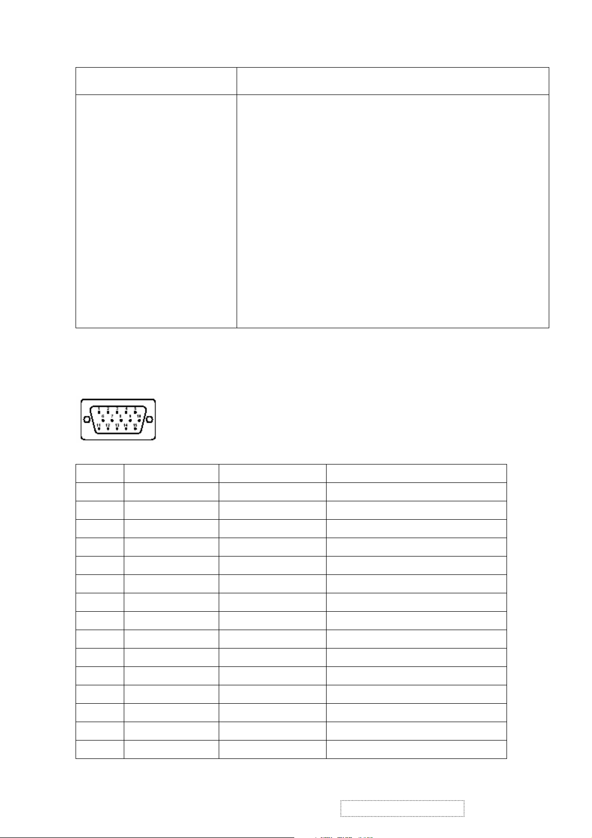
2.3. D-SUB CONNECTOR PINASSIGNMENT
1. VGA 640x350 @ 70Hz, 25.176MHz
Pin No. Symbol Signal Description
1 R RED 0.7vp-p (VIDEO)
2 G GREEN 0.7vp-p (VIDEO)
3 B BLUE 0.7vp-p (VIDEO)
4 GND GROUND
5 GND GROUND
6 GND GROUND
7 GND GROUND
8 GND GROUND
9 VCC_+5V PC +5V
10 GND GROUND
11 N.C.
12 DDC_SDA DDC1/2B TTL
13 DDC_SCL DDC1/2B TTL
14 VGA_VSYNC VSYNC TTL positive or negative
15 VGA_HSYNC HSYNC TTL positive or negative
ViewSonic Corporation
!
3
!
Confidential – Do Not Copy
VG500-2
Page 7
2.4 Main DC+12V Input (J800 on I/F Board)
Pin No. Symbol Function
1 GND Ground
2 DC+12V Main DC+12V Input
3 GND Ground
2.5 Audio Input Jack (J701 on I/F Board)
Pin No. Symbol Function
1 Ground
2 L_CH_Audio Input
3 R_CH_Audio Input
4 L_CH_Audio Return
5 R_CH_Audio Return
ViewSonic Corporation
!
4
!
Confidential – Do Not Copy
VG500-2
Page 8
2.6 Internal Connector & Pin Assignment
XGA Interface Board (PWB-0535)
CON1 : Connect with Control board
Pin No. Symbol Function
1 Mute
OSD, Audio Mute Function Button
2 SP- Adjust audio volume smaller
3 SP+ Adjust audio volume louder
4 Menu Call out or close the OSD menu or come back to the
previous menu
5 Down Choose the next one item or value
6 Up Choose the last one item or value
7 Sel Select
8 GND Ground
9 Amber Indicate the system in power saving mode
10 Green Indicate the system in active mode
11 GND Ground
12 Power Power on/off control port
CON3 : Connect to the PWB-0537, which is power/audio board
Pin No. Symbol Function
1 SENSOR Detect audio I/P signal
2 GND Ground
3 +12V DC+12V
4 GND Ground
5 CCFL_EN Backlight lamps ON(high)/Off(Low) control
6 GPIO2/PWM2 Brightness adjustments (Low Max./ Hi. Min.)
7 MUTE+ Audio Must control (High means SPK off, Low means On)
8 GND Ground
9 +5V DC+5V
10 +5V DC+5V
11 STDBY Audio Stand-by control (Hi means stand-by, Low means Normal)
12 VOLUME Speaker volume control (0V means Sound off, 1.2V means MAX.)
ViewSonic Corporation
!
5
!
Confidential – Do Not Copy
VG500-2
Page 9
CON5 : Output to panel
Pin No. Symbol Function
1 GND Ground
2 GND Ground
3 CLKH- Sampling Clock for line pixels
4 GND Ground
5 GND Ground
6 OB7 Blue data signal of odd pixel
7 OB6 Blue data signal of odd pixel
8 OB5 Blue data signal of odd pixel
9 OB4 Blue data signal of odd pixel
10 OB3 Blue data signal of odd pixel
11 OB2 Blue data signal of odd pixel
12 OB1 Blue data signal of odd pixel
13 OB0 Blue data signal of odd pixel
14 GND Ground
15 OG7 Green data signal of odd pixel
16 OG6 Green data signal of odd pixel
17 OG5 Green data signal of odd pixel
18 OG4 Green data signal of odd pixel
19 OG3 Green data signal of odd pixel
20 OG2 Green data signal of odd pixel
21 OG1 Green data signal of odd pixel
22 OG0 Green data signal of odd pixel
23 GND Grounding
24 OR7 Red data signal of odd pixel
25 OR6 Red data signal of odd pixel
26 OR5 Red data signal of odd pixel
27 OR4 Red data signal of odd pixel
28 OR3 Red data signal of odd pixel
29 OR2 Red data signal of odd pixel
30 OR1 Red data signal of odd pixel
31 OR0 Red data signal of odd pixel
32 GND Ground
33 GND Ground
34 VDDA DC+9V for panel D/A reference voltage to make gray scale smooth
35 VDDA DC+9V for panel D/A reference voltage to make gray scale smooth
36 VDDA DC+9V for panel D/A reference voltage to make gray scale smooth
37 VDDA DC+9V for panel D/A reference voltage to make gray scale smooth
38 VDDA DC+9V for panel D/A reference voltage to make gray scale smooth
ViewSonic Corporation
!
6
!
Confidential – Do Not Copy
VG500-2
Page 10
Pin No. Symbol Function
39 VDDA DC+9V for panel D/A reference voltage to make gray scale smooth
40 GND Ground
41 GND Ground
42 GND Ground
43 GND Ground
44 EPOL O/E reference voltage selection
45 HMS2_E Even pixel inverter for power saving and reducing EMI
46 HMS1_O Odd pixel inverter for power saving and reducing EMI
47 DHS_LP Latch pulse for per line
48 STH1 Trigger the first pixel per line
49 GND Ground
50 GND Ground
CON6 : Output to panel
Pin No. Symbol Function
1 GND Ground
2 GND Ground
3 VEEG DC-6V for frame dark
4 VEEG DC-6V for frame dark
5 VDDG DC+18V for frame white
6 VDDG DC+18V for frame white
7 CLKV Sampling Clock for frame line
8 STV1 Trigger the first line per frame
9 VDDD DC_3.3V for panel VCC
10 VDDD DC_3.3V for panel VCC
11 VDDD DC_3.3V for panel VCC
12 VDDD DC_3.3V for panel VCC
13 VDDD DC_3.3V for panel VCC
14 VDDD DC_3.3V for panel VCC
15 VCOM Panel flicker adjustment, Adjustable voltage from DC3.3V ~4V
16 VCOM Panel flicker adjustment, Adjustable voltage from DC3.3V ~4V
17 VCOM Panel flicker adjustment, Adjustable voltage from DC3.3V ~4V
18 VCOM Panel flicker adjustment, Adjustable voltage from DC3.3V ~4V
19 VCOM Panel flicker adjustment, Adjustable voltage from DC3.3V ~4V
20 VCOM Panel flicker adjustment, Adjustable voltage from DC3.3V ~4V
21 GND Ground
22 GND Ground
23 EB7 Blue data signal of even pixel
24 EB6 Blue data signal of even pixel
25 EB5 Blue data signal of even pixel
ViewSonic Corporation
!
7
!
Confidential – Do Not Copy
VG500-2
Page 11
26 EB4 Blue data signal of even pixel
Pin No. Symbol Function
27 EB3 Blue data signal of even pixel
28 EB2 Blue data signal of even pixel
29 EB1 Blue data signal of even pixel
30 EB0 Blue data signal of even pixel
31 GND Ground
32 EG7 Green data signal of even pixel
33 EG6 Green data signal of even pixel
34 EG5 Green data signal of even pixel
35 EG4 Green data signal of even pixel
36 EG3 Green data signal of even pixel
37 EG2 Green data signal of even pixel
38 EG1 Green data signal of even pixel
39 EG0 Green data signal of even pixel
40 GND Ground
41 ER7 Red data signal of even pixel
42 ER6 Red data signal of even pixel
43 ER5 Red data signal of even pixel
44 ER4 Red data signal of even pixel
45 ER3 Red data signal of even pixel
46 ER2 Red data signal of even pixel
47 ER1 Red data signal of even pixel
48 ER0 Red data signal of even pixel
49 GND Ground
50 GND Ground
POWER/AUDIO Board (PWB-0537)
JP2 : Connect to the I/F Board
Pin No. Symbol Function
1 Volume Speaker volume control (0V sound off, 1.2V sound Max.)
2 Stdby Audio standby control (High standby, Low normal)
3 DC+5V DC+5V
4 DC+5V DC+5V
5 GND Ground
6 MUTE+ Audio mute control (Voltage High speaker off, Low speaker on)
7 BRT Brightness adjustment (Low is max., High is Min.)
8 CCFL_EN Backlight lamps enable (ON/high, OFF/low)
9 GND Ground
10 DC+12V DC+12V
11 GND Ground
ViewSonic Corporation
!
8
!
Confidential – Do Not Copy
VG500-2
Page 12
12 SENSOR Detect audio I/P signal
P1 : Connect to inverter
Pin No. Symbol Function
1 DC+12V DC+12V
2 GND Ground
3 BRT Brightness adjustment (Low is Max., High is Min.)
4 DC+5V DC+5V
5 CCFL_EN Backlight lamps enable (ON/high, OFF/low)
CN701 : Connect to control board, control the audio
Pin No. Symbol Function
1 L- L_CH_SP_-Signal
2 L+ L_CH_SP_+Signal
3 GND_S1 Ground
4 R+ R_CH_SP_-Signal
5 R- R_CH_SP_+Signal
ViewSonic Corporation
!
9
!
Confidential – Do Not Copy
VG500-2
Page 13
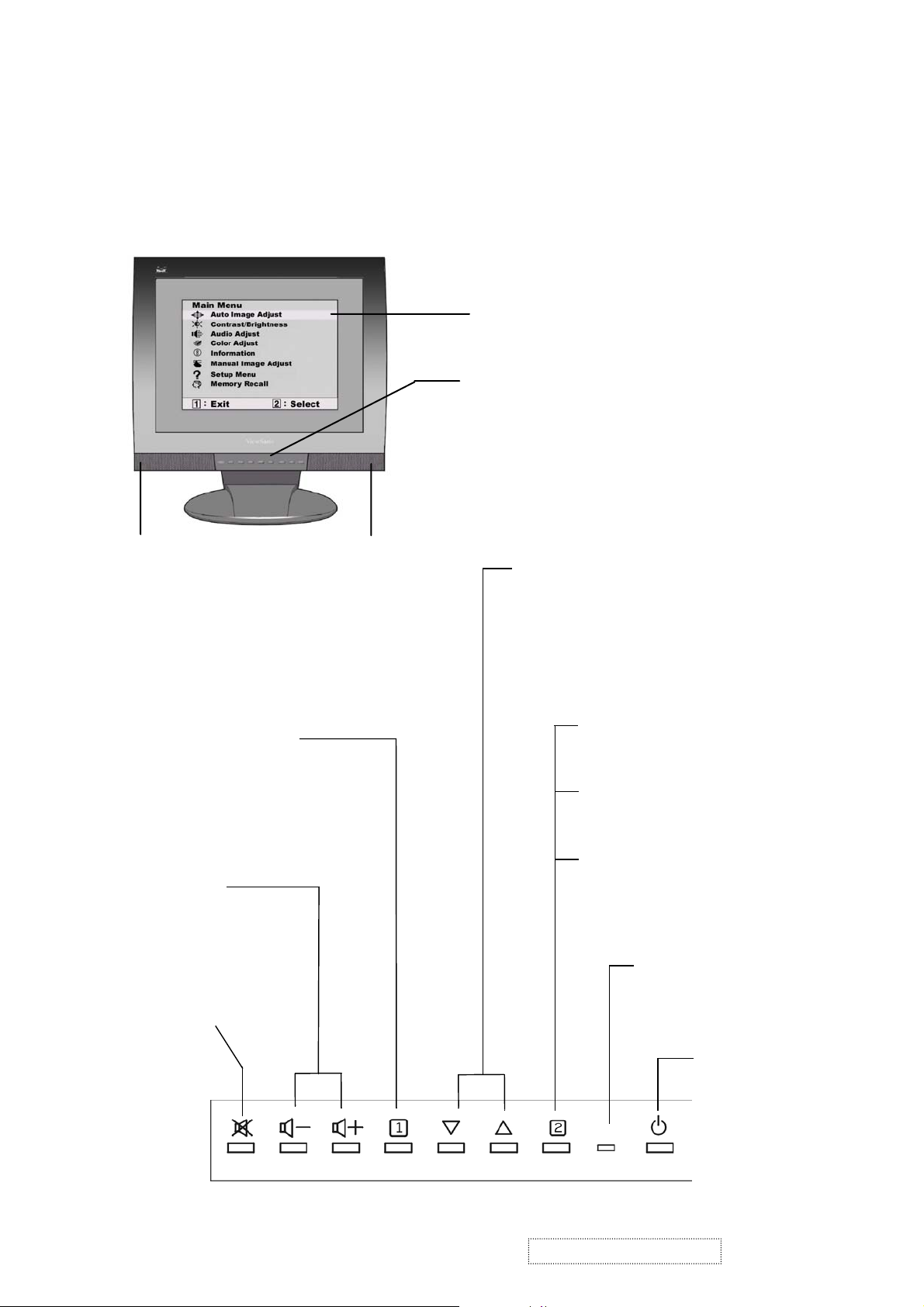
3. Front Panel Function Control Description
Use the buttons on the front control panel to display and adjust the OSD
controls which display on the screen. The OSD controls are explained at the
top of the next page and are defined in “Main Menu Controls” on page 9.
Main Menu
With OSD controls
Front Control Panel
shown below in detail
Speaker
Displays the Main Menu
or exits the control screen
and saves adjustments.
Decreases or
increases volume.
Temporarily silences
audio output.
Speaker
Scrolls through menu options and
adjusts the displayed control.
Also a shortcut to display the
Contrast adjustment control
screen.
Displays the control
screen for the highlighted
control.
Also toggles between two
controls on some
screens.
Also a shortcut to Auto
Image Adjust.
Power light
Green = ON
Orange = Power
Saving
ViewSonic Corporation
10
Confidential – Do Not Copy
Power
On/Off
VG500-2
Page 14
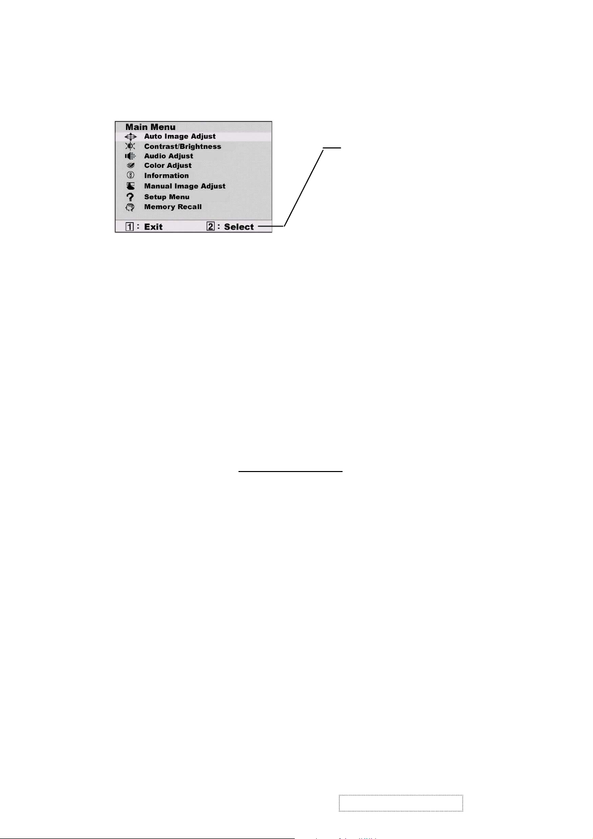
Do the following to adjust the screen image:
1
To display the Main Menu, press button [1].
The line at the bottom of the
screen tells you what you can
do next: Exit this menu or
Select the control that is
highlighted.
2
To highlight a control you want to adjust, press ▲or▼ to scroll up or down
the Main Menu.
3
To select the highlighted control, press button [2]. A control screen appears.
4
To adjust the control, press the up▲or down▼buttons.
5
To save the adjustments and exit the menu, press button [1] twice.
The following tips may help you optimize your display:
• Adjust your computer's graphic card so that it outputs a video signal 1024 x
768 @ 60 Hz to the LCD display. (Look for instructions on “changing
the refresh rate” in your graphic card's user guide.)
• If necessary, make small adjustments using H POSITION and V POSITION
until the screen image is completely visible
. (The black border around the
edge of the screen should barely touch the illuminated “active area” of the
LCD display.)
ViewSonic Corporation
11
Confidential – Do Not Copy
VG500-2
Page 15
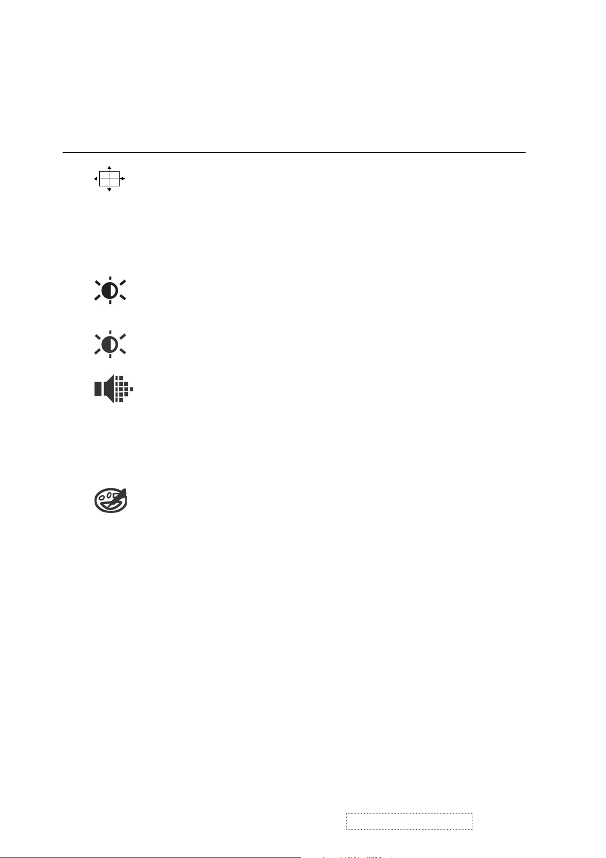
Main Menu Controls
Adjust the menu items shown below by using the up ▲ and down ▼ buttons.
Control Explanation
Auto Image Adjust
automatically sizes, centers, and fine tunes
the video signal to eliminate waviness and distortion.
Press the [2] button to obtain a sharper image.
NOTE:
Auto Image Adjust works with most common video
cards. If this function does not work on your LCD
display, then lower the video refresh rate to 60 Hz and set the
resolution to its pre-set value.
Contrast
adjusts the difference between the image background
(black level) and the foreground (white level).
Brightness
Audio Menu
Vol um e
adjusts background black level of the screen image.
controls are explained below:
increases the volume, decreases the volume, and mutes
the audio.
Mute
temporarily silences audio output.
Color Adjust
provides several color options: preset color
temperatures and Custom User Color which allows you to adjust
red (R), green (G), and blue (B). The factory setting for this
product is 6500K (6500°Kelvin).
9300K
— Adds blue to the screen image for cooler white (used
in most office settings with fluorescent lighting).
6500K
— Adds red to the screen image for warmer white and
richer red. Default setting.
5400K — Adds green to the screen image for a darker color.
Custom User Color
— Individual adjustments for red, green,
and blue.
1
To select color (R, G or B) press button [2].
2
To adjust selected color, press ▲ or ▼.
3
When you are finished making all color adjustments, press
button [1] twice.
ViewSonic Corporation
12
Confidential – Do Not Copy
VG500-2
Page 16

Control Explanation
Information
displays the timing mode (video signal input)
coming from the graphics card in your computer. See your
graphic card’s user guide for instructions on changing the
resolution and refresh rate (vertical frequency).
VESA 1024 x 768 @ 60 Hz (recommended) means that the
resolution is 1024 x 768 and the refresh rate is 60 Hertz.
Manual Image Adjust controls are explained below:
H. Size (Horizontal Size) adjusts the width of the screen image.
NOTE: Vertical size is automatic with your LCD display.
H./V. Position adjusts horizontal and vertical position of the
screen image. You can toggle between Horizontal and Vertical
by pressing button [2]. Horizontal moves the screen image to
the left or to the right. Vertical moves the screen image up and
down.
Fine Tune sharpens focus by aligning the illuminated text and/
or graphic characters.
NOTE:Trythe
Fine Tune
Sharpness adjusts the clarity and focus of the screen image.
Setup Menu controls are explained below:
Language allows you to choose the language used in the menus
Auto Image Adjust
control.
(see page 12) before using the
and control screens.
Resolution Notice
displays the recommended resolution for this
LCD display.
Enable allows the Resolution Notice to appear on-screen.
Disable will not allow the Resolution Notice to appear onscreen.
ViewSonic Corporation
13
Confidential – Do Not Copy
VG500-2
Page 17

Control Explanation
OSD Position allows you to move the on-screen display
menus and control screens.
OSD Timeout
sets the length of time an on-screen display
screen is displayed. For example, with a “15 second” setting, if
a control is not pushed within 15 seconds, the display screen
disappears.
OSD Background
allows you to turn the On-Screen-Display
background on or off.
Memory Recall returns adjustments to the original factory
settings if the display is operating in a factory Preset Timing
Mode listed in this user guide.
Exception: This control does not effect changes made with the
Custom User Color control.
ViewSonic Corporation
14
Confidential – Do Not Copy
VG500-2
Page 18

Short Cut Key
User control functions
Control buttons :
-
1. Press power button to power on whole LCD monitor set. Led on the power button will turn to
green.
2. Press "2" button while no OSD will activate the Auto Image Adjust function.
3. Press “up” and ‘down” button simultaneously will reset the contrast and brightness to default
value.
4. Press "1" button will enter OSD main menu.
5.
Press “volume plus”, “volume minus” can directly adjust the audio volume.
6. Press “mute” button can directly mute on or off the audio volume.
7. Press "1" and "2" button simultaneously will toggle 720x400 and 640x400 mode when input
720x400 or 640x400 mode.
+
1
2
8. Press
"1", "down", and "up" button simultaneously will do White Balance.
ViewSonic Corporation
15
Confidential – Do Not Copy
VG500-2
Page 19

4. Circuit Description
4.1 Inverter Board Circuit
The diagram of inverter board circuit is shown in Appendix (PWB-0538). The inverter supplies power for
backlight for the LCD panel.
4.2 Power supply Board Circuit
Please refer to power Schematic sheet in Appendix. The 12Vdc from adaptor output is fed into J800 as
power regulation of U801 (AO4403) input power and inverter main power on pin 1 of CN830. The U801 can
provide two independent power sources: a) The 5Vdc will be for main board power. ; b) The another 10.5Vdc
will output as audio power at when audio jet is inserted.
4.3 Scaling controller Board Circuit
The Scaling IC U005 is to convert the input signal from VGA, SXGA and UXGA to a SXGA resolution that
panel can acknowledge.
The scaling IC of MRT MASCOT V2 is a highly integrated System-on-a- Chip with very powerful functions,
including integrated 8 bit triple-channel ADC/PLL, programmable OnPanel timing controller, embedded
microcontroller with parallel ROM interface, OSD engine, sRGB compliance, and PWM back light intensity
control.
The Scaling IC features an integrated timing controller (TCON) that connects directly to commercially
available row and column drivers. All TCON signals OCLK, ECK, ORGB, ERGB, OSP, ESP, OPOL, OINV,
EINV on pin 68 to pin 79 of U005 have programmable drive strengths and can be disabled to control Panel.
The flash memory chip of U001 contains codes via parallel data bus interface to communicate
with Scaling IC U005.
The DDC memory chip of U004 stores DDC data and the NVRAM chip stores timings and setting data.
Since the NVRAM has to get series number information data from DDC chip, both their SDA and SCL
ports connected together. In order to avoid conflict on I C interface during the DDC transfer from U004,
2
the electrical switching of U009 is isolated and controlled by scaling IC pin GPIO7.
4.4 Audio Circuit
The audio Right/Left channels are fed into pin 6 /8 of sound AMP U701 (AN7522) while Audio plug is
inserted on J701 jack. The sound output amplitude will depend on this bias voltage on pin 9 of U701, which
is always controlled by Q702. When mute is activated, the Q703 will be forced to saturation to block sound
output. When standby is activated, the sound outputs of U701 will drive speakers via CN701 connecter.
ViewSonic Corporation
!
16
!
Confidential – Do Not Copy
VG500-2
Page 20

5. Adjusting Procedure
SERVICE TOOLS & EQUIPMENT REQUIRED
1. SIGNAL GENERATOR: Chroma 2237 or equivalent
2. MULTIMETER Fluke 45 or equivalent
3. SCREW DRIVER
4. OSCILLOSCOPE Tektronik TDS3054 digital oscilloscope or equivalent
5. SOLDER IRON
6. SOLDER
Panel adjustment:
1. Select 1024 x 768@60Hz mode, and Crosshatch pattern
2. Press “ Auto image set up” -------Direct access “2” Key
3. Brightness set at maximum
4. Switch pattern to full screen “pixel on/off” pattern with R, B color off and Green on.
Green color level set at level 255.
5. Adjust VR01 until whole screen display stable and flicker free.
Function Test and Alignment Procedure
Product
15” LCD MONITOR MODEL: VG500-2
Test Equipment
Color Video Signal & Pattern ( XGA 1024 x 768 @ 60 Hz 5 white
block Pattern )
Hot Key
1) All Mode Reset
Press “ ” and "power" buttons simultaneously and "Power on" with signal hold
on for 3 seconds. The OSD screen will show "Software Version".
2
ViewSonic Corporation
!
17
!
Confidential – Do Not Copy
VG500-2
Page 21

2)Press "
" button , the OSD will show “ Factory Init. ”
2
Then “ϧ” button for 3 seconds, the OSD will show "Memory Recall"
to initialize all modes.
3) Burn In Mode
Press " " button , the OSD will show “Burn In Mode Setting ”
2
Then set "ϧ" or "ϰ" buttons , you can find “ set Burn In Mode ”
Information about this monitor
ViewSonic Corporation
!
18
!
Confidential – Do Not Copy
VG500-2
Page 22

4) White Balance
Press "ϧ" "ϰ" and " " buttons simultaneously for 3 seconds to
1
set White Balance Mode.
Please set the screen on 1024x768 @ 60 Hz resolution 5 white block pattern
5) Power Lock
Press "ϰ" and " “ " buttons simultaneously for 10 seconds , and
1
the Power will be locked. Repeat the action , and the power will
be unlocked.
ViewSonic Corporation
!
19
!
Confidential – Do Not Copy
VG500-2
Page 23

6) OSD Lock
Press "ϧ" and " " buttons simultaneously for 10 seconds, and the
1
OSD will be locked. Repeat the action and the OSD will be unlocked.
ViewSonic Corporation
!
20
!
Confidential – Do Not Copy
VG500-2
Page 24

DD C Recorder User Manual
1. Connect the recorder (with Keyport II )to the printer port on your PC.
2. Insert diskette into your PC's floppy drive, then turn on the PC power.
ʳ
ʳ
3. A setup main menu will be appear as below :
ʳ
Select DDC Function Mode
ʳ
[1
ʳ
[2 Auto Replace DDC Date ʳ
ʳ
[3 Bar Code : xtttddsssss ʳ
ʳ
[4 ʳ ʳʳ
ʳ
[5 [F5] : Check DDC1 [F6] : Check DDC2 ʳ
ʳ
[6 ʳ ʳʳʳʳ ʳ
ʳ
ʳ ʳʳʳ ʳ
ʳ
ʳ
[7] Mode Name : L5CNSE29.HWP ʳ
ʳ
[8] Serial NO : sssss ʳ
ʳ
[9] DDC Year : 2003 ʳ
ʳ
[A] DDC Weeks : 01 ʳ
ʳ
4. Recoding Process :
(1) Choose a correct mode name
ʳ
(2)Press [Caps Lock]then key in the bar code number STHTAA00001,
ʳ
And then Press [Enter].
The screen shows a green color sentence "Receive DDC Data OK" ʳ
ʳ
(3) Be sure both the bar code number and DDC2 data are correct.
ʳ
(4)After set power off --on, press[F5]to make sure the DDC1
ʳ
and bar code number are correct.
5.Checking Process :
(1) After SET ON ,Press [F5]then verify DDC1 data .Press[F6] to
verify DDC2 data.
(2)During verification for either DDC1 or DDC2 a green color sentence will appear
ʳ
"Receive DDC Data OK", and will disappear after 10 seconds.
ViewSonic Corporation
!
21
!
Confidential – Do Not Copy
VG500-2
Page 25

ʳ
ʳ
ʳ
ʳʳ ʳ
ʳʳ ʳ
ʳʳ ʳ
ʳʳ ʳ
ʳʳ ʳ
ʳʳ ʳ
ʳʳ
ʳʳ ʳ
ʳʳ ʳ
ʳʳ ʳ
ʳʳ
ʳʳ
ʳ
ʳ
ˉˁʳ˧˻˸ʳ˹˿˿˼˺ʳ˼ʳ˴ʳ˸˴˿˸ʳ˹ʳ˗˗˖ʳ˷˴˴ʳˍʳ
ʳ
ʳ
ʳ ʳ
ʳ
ʳ
ʳ
ʽ˗˗˖ʳ ʳ ˃ʳ ʳ ʳ ʳ ʳ ˄ʳ ʳ ʳ ʳ ˅ʳ ʳ ʳ ʳ ˆʳʳʳˇʳʳʳʳˈʳʳʳʳˉʳʳʳʳˊʳʳʳʳˋʳʳʳʳˌʳʳʳʳ
ʳ
˔ʳʳʳʳ˕ʳʳ˖ʳʳʳʳ˗ʳʳʳ˘ʳʳʳ˙ʳ
ʳ
˃˃˃˃ʳ ʳ ˃˃ʳ ʳ ʳ ˙˙ʳ ʳ ˙˙ʳ ʳ ˙˙ʳ˙˙ʳ ʳ ˙˙ʳ ʳ ˙˙ʳ ʳ ˃˃ʳ ʳ ˅˅ʳ ʳ ˙˃ʳ ʳ ˗ˋʳ ʳ ˄˅ʳ ʳ ˃˄ʳ ʳ
ʳ
˃˃ʳ ʳ ˃˃ʳ ʳ ˃˃ʳ
ʳ
˃˃˄˃ʳ˪˪ʳˬˬʳ˃˄ʳ˃ˆʳʳʳˉˋʳʳ˄˘ʳ˄ˊʳʳʳˊˋʳʳ˘˔ʳˌ˗ʳˌ˘ʳʳˌˌʳʳˈˋʳʳˇ˖ʳʳ
ˌˆʳ ʳ ˅ˉʳ
˃˃˅˃ʳ ʳ ˅˄ʳ ʳ ˇ˖ʳ ʳ ˈˇʳ ʳ ˕˙ʳ ʳ ˘˘ʳ ʳ ˃˃ʳˆ˄ʳ ʳ ˇ˔ʳ ʳ ˇˈʳ ʳ ˇ˔ʳ ʳ ˉ˄ʳ ʳ ˇ˖ʳ ʳ ˃˄ʳ ʳ
˃˄ʳ ʳ ˃˄ʳ ʳ ˃˄ʳ
˃˃ˆ˃ʳ ʳ ˃˄ʳ ʳ ˃˄ʳʳʳ˃˄ʳʳ˃˄ʳʳ˃˄ʳʳ˃˄ʳʳˉˇʳʳ˄ˌʳʳʳ˃˃ʳʳˇ˃ʳʳʳˇ˄ʳʳ˃˃ʳʳ˅ˉʳ
ˆ˃ʳ ʳ ˄ˋʳ ʳ ˋˋʳ
˃˃ˇ˃ʳ ʳ ˆˉʳ ʳ ˃˃ʳʳʳˆ˃ʳʳ˘ˇʳʳ˄˃ʳʳ˃˃ʳʳ˃˃ʳʳ˄ˋʳʳʳ˃˃ʳʳ˃˃ʳʳ˃˃ʳʳ˙˗ʳʳ˃˃ʳ
ˆˋʳʳˇ˕ʳʳ˄˙ʳ
˃˃ˈ˃ʳ ʳ ˆ˙ʳ ʳ ˃ˋʳ ʳ ʳ ˃˃ʳ ʳ ˃˔ʳ ʳ ˅˃ʳ ʳ ˅˃ʳ˅˃ʳ ʳ ʳ ˅˃ʳ ʳ ˅˃ʳ ʳ ˅˃ʳ ʳ ˃˃ʳ ʳ ˃˃ʳ ʳ ʳ ˃˃ʳ
˙˙ʳʳ˃˃ʳʳ˕˖ʳ
˃˃ˉ˃ʳ ʳ ˕˖ʳ˕˖ʳ˕˖ʳ˕˖ʳ˕˖ʳ˕˖ʳ˕˖ʳ˕˖ʳ˕˖ʳ˃˔ʳ ʳ ˅˃ʳ ʳ ˅˃ʳ ʳ ˃˃ʳ ʳ ˃˃ʳ ʳ ˃˃ʳ ʳ
˙˖ʳ
˃˃ˊ˃ʳʳʳ˃˃ʳʳˉˋʳʳˊ˃ʳʳ˅˃ʳʳˊˉʳʳˉˉʳʳˆˈʳʳʳˆ˄ʳʳ˃˔ʳʳ˅˃ʳʳ˅˃ʳʳ˅˃ʳʳ˅˃ʳ
˅˃ʳʳ˃˃ʳʳ˖˦ʳ
˗˗˖ʳ˗˴˴ʳ˥˸˶˸˼˸˷ʳˍʳ˦˧˛˧˔˔˃˃˃˃˄ʳ ʳ
Zfbs0Xfflt>3114012!!!Tfsjbm!Op!>11112!
ʳʳ
ʳʳ ʳʳ ʳʳ ʳʳ ʳʳ ʳʳ ʳʳʳ
ʳ
ʳ
ʳ
ViewSonic Corporation
!
22
!
Confidential – Do Not Copy
VG500-2
Page 26

N
6. Trouble Shooting Flow Chart
No picture Appear
Picture
shows
Scaling IC (U005)
Hangs
Reset the Scaling IC
(U005 and U001) by
pushing the power
key or re-plugging the
DC 12V cable
ext
Still no
Picture
Does the LED
light up
No
LED display is
amber
No
Is it entering into
power saving mode
Restart PC signal
to ensure H. V.
sync are not
Ye s
Ye s
Ye s
absent
No
The Voltage across
Check O/P of U801 at
The Voltage at
L802 O/P is 5V
The Voltage across
C801 is 12V
Ye s
pin10
pin7,
Ye s
Ye s
Q702 is 5V
No
No
No
No
Replace F801
Replace U801
Replace U802
Replace Q702
End
ReplaceU001
ReplaceU005
MASCOT V2
End
Still no
Picture
End
Ye s
No
Check U004
Replace U004
Ye s
No
Check U009
Replace U009
Ye s
Replace U001
ViewSonic Corporation
!
23
!
Confidential – Do Not Copy
VG500-2
Page 27

N
ext
The Voltage of I001
#2 is 3.3V
Replace U001
Still No LED
Check Y001 crystal
clock
Yes
Replace U005
(MASCOT V2 )
No
No
Replace I001
Replace Y001, C003,
C004
ViewSonic Corporation
End
!
24
!
Confidential – Do Not Copy
VG500-2
Page 28

The Ver. Or Hor.
A
A
Sync. Does not hold
re the output
MV2(CLK,H,V,
DE) normal
No
re theinput
waveforms of
M V2 normal
Yes
PEPLACE MV2
Yes Yes
Are two flex cables
attached firmly at
CON5, CON6
No
Tighten two flex
cables at
CON5,CON6
End
Are two flex cables
attached firmly at
the LCD panel
connectors
Ye s
Replace V901 (LCD
panel)
End
No
Tighten two flex
cables at
CON5,CON6
End
End
ViewSonic Corporation
!
25
!
Confidential – Do Not Copy
VG500-2
Page 29

No sound
Check if Audio jack
properly insert
Yes
Check if mute key
is pressed
NO
Check if CN701 is
connected to U701
properly
YES
U701 #1 voltage is
12V
Yes
Check U701 output
#2,#4,#10,#12 are
normal
YES
No
Press mute key again
to release
Check U801 output
#7 is normal
No
Replace U801
Replace U701
ViewSonic Corporation
No
!
26
!
Confidential – Do Not Copy
VG500-2
Page 30

7. Recommended Spare Parts List
Item ViewSonic P/N Ref. P/N Location
1 B-MB-0201-0787
2 B-SB-0221-0560
3 B-KB-0207-0041
4 B-AC-0215-0044
5 C-FP-0301-0401
6 M-CV-0830-2473
7 C-BC-0302-0535
8 M-MS-0808-8273
9 M-MS-0808-8278
10 M-MS-0808-8279
11 M-MS-0808-8275
12 PL-PS-0715-0209
13 M-MS-0808-8277
14 PL-FK-0709-0132
15 M-MS-0808-8284
16 M-MS-0808-8276
17 M-MS-0808-8285
18 M-CV-0830-2474
19 M-MS-0808-8891
20 M-MS-0808-8272
21 M-MS-0808-8271
22 PL-PD-0714-0072
23 PL-PD-0714-0073
24 PL-PD-0714-0074
25 M-MS-0808-8890
26 M-MS-0808-8889
27 M-MS-0808-8280
28 M-MS-0808-8281
29 A-AD-0114-0193
30 M-MS-0808-8287
31 M-MS-0808-8288
32 A-CD-VG500-2
33 A-PC-0106-0169
34 A-PC-0106-0170
35 M-MS-0808-8286
36 M-WR-0828-0656
37 A-AU-0120-0035
38 A-VC-0101-0272
39 P-BX-0601-0878 9513340156 1P01 100
40 P-FM-0602-0608 9522880157 1P02 100
41 P-FM-0602-0609 9522880257 1P03 100
42 M-LCD-0826-0169
43 M-FC-0809-0080
44 E-SK-0412-0076
45 E-SK-0412-0077
46 E-D-0403-2128 6640007723 DA01 20
47 E-D-0403-2126
48 E-IC-0401-2562
49 E-IC-0401-2888 6640010550 I002 20
50 E-IC-0401-2571
51 E-IC-0401-2570 6646021652 I004 20
52 E-Q-0402-1180 6622002257 Q002 20
53 E-Q-0402-7017 6623002956 Q003 20
54 E-Q-0402-1564 6626007054 Q004 20
55 E-Q-0402-1561 6621039854 Q005 20
56 E-Q-0402-1563 6626007053 Q006 20
57 E-Q-0402-1561 6621039854 Q007,Q008 20
58 E-IC-0401-2895 6647106005 U001 20
59 E-IC-0401-2891 6647024302 U001 20
60 E-IC-0401-2892 6647026357 U002 20
61 E-IC-0401-2890 6646033553 U003 20
5097616700
5097617100
5097616800
5097616900
5733715802
5733715902
5733715702
5731274500
5731708100
5731708200
5731433800
5733716002
5731593000
5733636902
5733716200
5731433901
5736138100
5733716102
5733576902
5731274401
5731274301
5736138200
5736138300
5736138400
5733576802
5733422902
5733422700
5733422800
5061369420
5784011204
5784011205
5030043002
5056705900
5056705939
5784010501
5057900521
5784010102
5784011503
5051253608
5784610007
5055123300
5055123301
6613000554
6640003862
6646021653
ViewSonic Corporation
MAIN Board Ass’ y PWB-0535
Inverter Board Ass'y PWB-0538
Key Pad Board Ass'y PWB-0536
Audio&Power Board Ass'y PWB-0537
F/C
F/C2 (Speaker cover)
Back Cover
SHIELD Plate
Hinge (R)
Hinge (L)
Mounting Bracket
Base
Code keeper
Button (Function key)
INDICATE (LED Lens)
Kensington Security Slot
Mount Rubber
Hinge Cover
Neck2 (Back)
Neck Plate
Base Plate
Foot Rubber 1
Foot Rubber 2
Foot Rubber 3
Neck 1 (Front)
View Sonic Logo
Bird Logo
Name Plate
Power ADAPTER(LITEON)
Key Pad Wire 12PIN
Key Pad Wire 5PIN
User's Guide(CD-ROM)
Power Cord (UL)
Power Cord (VDE)
Key TO DC-AMP Wire
Inverter Wire
AUDIO Cable
VGA Cable
Carton box
EPS -Top
EPS-Bottom
CPT Panel
UL2896 L=39mm k-50 p=0.5
SPEAKER(L)
SPEAKER(R)
KA431
BAV99 75V 0.15A
RC1117M-3.3V
AIC117-33CY(AK33)
RT9164CG
RT9161A-33CG
MMBT3904 60V 0.1A
MMBT3906
SI2303DS
DTC114TKA
SI2301DS
DTC114TKA
M8064 MRT MCU
W78E65P WINBOND MCU
CAT24WC16J-TE13
SN74LVC14ADR
!
!
!
Description
CABINET
PACKAGE
ELECTRONIC
27
Confidential – Do Not Copy
PWB-0535 10
PWB-0538 10
PWB-0536 10
PWB-0537 10
3C06 20
3C07A 20
3C01 20
3C14 20
2B01 20
2B02 20
3C02 20
2B05 20
3C13 20
3C07B 20
3C07C 20
3C05 20
3C15 20
2B08 20
2B07 20
2B03 20
2B04 20
2B04C 20
2B04D 20
2B04E 20
2B06 20
2B09 20
3C09 20
3C08 20
ADAPT 30
CON1W 20
CON3W 20
Y001 100
P001 100
P002 100
CON7W 100
CON8W 100
AUDIO 100
15P1 100
PANEL 5
FFC1 20
SPK-L 20
SPK-R 20
DN01 20
I001 20
I003 20
VG500-2
Q'ty
Page 31

Item ViewSonic P/N Ref. P/N Location
62 E-IC-0401-2893 6647051834 U004 20
63 E-IC-0401-2894 6647053550 U005 20
64 E-Q-0402-1622 6644009053 U007 20
65 E-IC-0401-2407 6646021651 U008 20
66 E-R-0405-6578 5162161020 VR01 20
67 E-X-0415-0135 6699114210 Y001-Y002 20
68 E-D-0403-2072 6615009858 ZD01-ZD04 20
69 E-D-0403-2127 6618018154 LED1 20
70 M-SW-0815-0187 5054512951 S101-S108 20
71 E-D-0403-2047 6613003059 D701 20
72 E-FS-0410-0099
73 M-MS-0808-8888
74 E-IC-0401-2568 6644005851 U701 20
75 E-FS-0410-0112 5054430090 F001 20
76 E-IC-0401-2520 6646000650 I001 20
77 E-IC-0401-2889 6645010202 I002 20
78 E-L-0407-1589 5062128355 L001 20
79 E-Q-0402-1180 6622002257 Q001 20
80 E-Q-0402-1621 6626004652 Q003-Q006 20
81 E-T-0408-0513 5061376800 T001-T002 20CD-T-1032-575T
5054440003
5056302056
S524A40X21
MASCOT V2 MRT
SI4435DY-TI-A 30V 8A
RT34063ACS
0.3W B 1.0K OHM M
12M CRYSTAL
MMSZ5232B
DIODE LED
TACT SW. DC12V50MA
RLS4148
FUSE 6125FA4A 125V/4A
EAR-PHONE JACK LJE0359A
AN7522
63V/3A 3216FF-3A-TR
OZ960S
TPC-8401
YC54T*4R7M 4.7UHM
MMBT3904 60V 0.1A
2N7002LT1
Description
F801 20
J701 20
Q'ty
ViewSonic Corporation
!
28
!
Confidential – Do Not Copy
VG500-2
Page 32

VG500-2 BOM LIST (PCB-MAIN)
Item ViewSonic P/N Ref. P/N Description Location
1
3
4
5
6
7
8
9
10
11
12
13
14
15
E-C-0404-4903 5240610191 CAPACITOR MONOLITHIC SMD REEL 100P 0603 C34,C35,C36,C37,C50,C51,
16
17
18
19
20
21
22
23
24
25
E-D-0403-2128 6640007723 IC VOLTAGE REGULATOR KA431AZ DA1
26
E-D-0403-2126 6613000554 DIODE SMD SWITCHING BAV99 DN1,DN2,DN3
27
28
29
30
E-IC-0401-2562 6640003862 IC VOLTAGE REGULATOR RC1117M-3.3 I1
31
E-IC-0401-2836 6640003858 IC VOLTAGE REGULATOR LT1117CST-3.3 I2
32
E-IC-0401-2571 6646021653 IC LDO RT9164CG I3
33
E-IC-0401-2570 6646021652 CHIP BEAD RT9161A33CG I4
34
35
36
37
38
E-Q-0402-1180 6622002257 TR NPN SMD MMBT3904 Q1,Q2
39
E-Q-0402-7017 6623002956 TR PNP SMD MMBT3906 Q3
40
E-Q-0402-1564 6626007054 TR FET MOS SI2303DS/FDN360P Q4
41
E-Q-0402-1561 6621039854 TR NPN HF DTC114TKA/KSR1110 Q5,Q7,Q8,Q10
42
E-Q-0402-1563 6626007053 SI2301DS/FDN360P/AO3401 Q6,Q9
43
44
45
46
47
E-R-0405-7078 5134347209 RESISTOR.THICK FILM CHIP 0603 1/16W 4.7K R4,R5,R11,R36,R37
48
49
50
51
52
53
54
55
56
57
5782510261 CONNECTOR T-S12BZR CON1
5782511011 CONNECTOR T-B12B-ZR CON3
5782711011 CONNECTOR 1216-064-15S-AAC CON4
5782971502 CONNECTOR IL-FHR-50S-HF CON5,CON6
5240615191 CAPACITOR MONOLITHIC SMD REEL 150P 0603 CP1
5230656291 CAPACITOR MONOLITHIC SMD REEL 5600P 0603 CZ1
5218007991 CAPACITOR ELECTROLYTIC MVY 100uF/16V C1
5230013991 CAPACITOR MONOLITHIC SMD REEL 0.1U 0603 C2,C5,C6,C7,C8,C9,C10,C11,C12,C13,C14,C17,C19,
C21,C22,C25,C26,C28,C33,C39,C42,C46,C48,C59,C60,
C61,C62,C63,C64,C65,C66,C67,C68,C69,C70,C71,C72,
C73,C76,C129,C133,C134,C136,C141,C145,C146,C151,
C154
5240622091 CAPACITOR MONOLITHIC SMD REEL 22P 0603 C3,C4,C78,C79
5250810591 CAPACITOR MONOLITHIC SMD REEL IUF 0805 C15
5214020202 CAPACITOR ELECTROLYTIC MVY 470uF/16V C16
5218006391 CAPACITOR ELECTROLYTIC MVY 220uF/16V C18,C140,C149,C153
5230610391 CAPACITOR MONOLITHIC SMD REEL 0.01U 0603 C23,C55,C56
5240610091 CAPACITOR MONOLITHIC SMD REEL 10P 0603 C29,C30,C31,C32
C53
5218007991 CAPACITOR ELECTROLYTIC MVY 100uF/16V C38,C40,C43,C44,C45,C128
5218008891 CAPACITOR ELECTROLYTIC MVY 22uF/16V C41
5218007891 C47,C77,C130,C137,C138,C144,
CAPACITOR ELECTROLYTIC MVY 10uF/16V
5240647091 CAPACITOR MONOLITHIC SMD REEL 47P 0603 C49,C52,C80,C81,C82,C83,C84,C85,C86,C87,C88,C89,
5230647291 CAPACITOR MONOLITHIC SMD REEL 4700P 0603 C54,C57,C58
5218012091 CAPACITOR ELECTROLYTIC MVY 47uF/25V C131,C132,C143
5240612191 CAPACITOR MONOLITHIC SMD REEL 120P 0603 C135
5240633191 CAPACITOR MONOLITHIC SMD REEL 330P 0603 C139
5218011991 CAPACITOR ELECTROLYTIC MVY 22uF/25V C142
6613003753 DIODE SMD SWITCHING 1N4148 D1
6615002200 ZENER DIODE SR24 D2,D3,D4,D5,D6
6615025153 TZM5234B/TZQ5234B/MMSZ5234B D7
5062130401 CHIP BEAD 2CB321611A700 L1,L2,L3,L4,L5,L11,L15
5062134801 INDUCTOR MULTILAY CHIP 2CI321611-R15 L10
5062128352 COIL CHOKE SS1003151MS/YC104R*151M L12
5062135100 COIL CHOKE SMD YC54*680K/SR0604680KS L13,L14
5160310156 RESISTOR NETWORK SMD REEL 4.7K*4 RP2,RP3
5160310140 RESISTOR NETWORK SMD REEL 68R*4
5134351109 RESISTOR.THICK FILM CHIP 0603 1/16W 510R R2,R1
5134315109 RESISTOR.THICK FILM CHIP 0603 1/16W 150R R3
5134310209 RESISTOR.THICK FILM CHIP 0603 1/16W 1K R6,R7,R13,R8,R9,R47,R49,R55
5134310309 RESISTOR.THICK FILM CHIP 0603 1/16W 10K
5134310109 RESISTOR.THICK FILM CHIP 0603 1/16W 100R
5134310409 RESISTOR.THICK FILM CHIP 0603 1/16W 100K R17
5134351209 RESISTOR.THICK FILM CHIP 0603 1/16W 5.1K R18
5134300009 RESISTOR.THICK FILM CHIP 0603 1/16W 0 OHM R30,R31
5134312109 RESISTOR.THICK FILM CHIP 0603 1/16W 120R R21,R23,R24,R26,R27,R29
5134175099 RESISTOR.THICK FILM CHIP 0603 1/16W 75R1% R22,R25,R28
5134322009 RESISTOR.THICK FILM CHIP 0603 1/16W 22R R34,R32
C147,C148,C150,C152
C90,C91,C92,C93,C94,C95,C96,C97,C98,C99,C100,
C101,C102,C103,C104,C105,C106,C107,C108,C109,C110,
C111,C112,C113,C114,C115,C116,C117,C118,C119,C120,
C121,C122,C123,C124,C125,C126,C127
RP4,RP5,RP6,RP7,RP8,RP9,
RP10,RP11,RP12,RP13,RP14,
RP15
R10,R20,R44,R46,R48,R70,
R75
R14,R15,R16,R33,R35,R38,
R39,R40,R41,R51,R57,R61,
R62,R63
ViewSonic Corporation
!
29
!
Confidential – Do Not Copy
VG500-2
Page 33

Item ViewSonic P/N Ref. P/N Description Location
58
59
60
61
62
63
64
65
66
67
68
69
70
71
72
73
74
E-IC-0401-2892 6647026357 IC MEMORY EEPROM 24LC16 U2
75
E-IC-0401-2893 6647051834 S524C20D11/BR24C02F-WE2/AT24C02 U4
76
E-IC-0401-2894 6647053550 SCALLOR MASCOT V II U5
77
E-Q-0402-1622 6644009053 IC MOSFET P-CH SI4435DY-T1-A 30V 8A SD-8 U7
78
E-IC-0401-2407 6646021651 IC DIGITAL PFM RT34063A U8
79
E-IC-0401-2569 6646010808 IC ANALOG DUAL4-CH BUFFER 74HCT4052 U9
80
E-R-0405-6578 5162161020 RESISTOR VR 1K 0.1W VR1
81
E-X-0415-0135 6699114210 CRYSTAL 20PPM 20PF 12MHZ HC-49U/S QE Y1,Y2
82
E-D-0403-2072 6615009858 ZENER DIODE MMSZ5232B ZD1,ZD2,ZD3,ZD4
83
5134322109 RESISTOR.THICK FILM CHIP 0603 1/16W 220R R43,R42
5134315109 RESISTOR.THICK FILM CHIP 0603 1/16W 150R R50,R53,R54,R71
5134322209 RESISTOR.THICK FILM CHIP 0603 1/16W 2.2K R56,R74,R82
5134315009 RESISTOR.THICK FILM CHIP 0603 1/16W 15R R60
5134310509 RESISTOR.THICK FILM CHIP 0603 1/16W 1MR R65
5136006800 RESISTOR THICK FILM CHIP430R 0.22R 1/4W 0805 R72
5134315309 RESISTOR.THICK FILM CHIP 0603 1/16W 15K R73
5134120209 RESISTOR.THICK FILM CHIP 0603 1/16W 2K 1% R76
5134127029 RESISTOR.THICK FILM CHIP 0603 1/16W 27K 1% R77
5134327209 RESISTOR.THICK FILM CHIP 0603 1/16W 2.7K R78
5136004622 RESISTOR THICK FILM CHIP430R 1W 2512 R79
5134375209 RESISTOR.THICK FILM CHIP 0603 1/16W 7.5K R80
5134110009 RESISTOR.THICK FILM CHIP 0603 1/16W 100R 1% R81
5134162009 RESISTOR.THICK FILM CHIP 0603 1/16W 620R 1% R83
5134112519 RESISTOR.THICK FILM CHIP 0603 1/16W 1.25K 1% R84
5134118099 RESISTOR.THICK FILM CHIP 0603 1/16W 18 1% R85
6647024302 W78E65P-40 PLCC 44PIN WINBOND U1
ViewSonic Corporation
!
30
!
Confidential – Do Not Copy
VG500-2
Page 34

VG500-2 BOM LIST CABINET & KEY-CONTROL PCB
Item ViewSonic P/N Ref. P/N Location Q'ty
C-FP-0301-0401 5733715802 3C06
1
M-CV-0830-2473 5733715902 3C07A
2
C-BC-0302-0535 5733715702 3C01
3
M-MS-0808-8273 5731274500 3C14
4
M-MS-0808-8278 5731708100 2B01
5
M-MS-0808-8279 5731708200 2B02
6
M-MS-0808-8275 5731433800 3C02
7
PL-PS-0715-0209 5733716002 2B05
8
M-MS-0808-8277 5731593000 3C13
9
PL-FK-0709-0132 5733636902 3C07B
10
M-MS-0808-8284 5733716200 3C07C
11
M-MS-0808-8276 5731433901 3C05
12
M-MS-0808-8285 5736138100 3C15
13
M-CV-0830-2474 5733716102 2B08
14
M-MS-0808-8891 5733576902 2B07
15
M-MS-0808-8272 5731274401 2B03
16
M-MS-0808-8271 5731274301 2B04
17
PL-PD-0714-0072 5736138200 2B04C
18
PL-PD-0714-0073 5736138300 2B04D
19
PL-PD-0714-0074 5736138400 2B04E
20
M-MS-0808-8890 5733576802 2B06
21
M-MS-0808-8889 5733422902 2B09
22
M-MS-0808-8280 5733422700 3C09
23
M-MS-0808-8281 5733422800 3C08
24
A-AD-0114-0193 5061369420 ADAPT
25
M-MS-0808-8287 5784011204 CON1W
26
M-MS-0808-8288 5784011205 CON3W
27
A-CD-VG500-2 5030043002 Y001
28
A-PC-0106-0169 5056705900 P001
29
A-PC-0106-0170 5056705939 P002
30
M-MS-0808-8286 5784010501 CON7W
31
M-WR-0828-0656 5057900521 CON8W
32
A-AU-0120-0035 5784010102 AUDIO
33
A-VC-0101-0272 5784011503 15P1
34
P-BX-0601-0878 9513340156 1P01
35
P-FM-0602-0608 9522880157 1P02
36
P-FM-0602-0609 9522880257 1P03
37
38
M-FC-0809-0080 5784610007 FFC1
39
E-SK-0412-0076 5055123300 SPK-L
40
E-SK-0412-0077 5055123301 SPK-R
41
E-D-0403-2127 6618018154 LED1
42
M-SW-0815-0187 5054512951 S101-S108
43
44
45
46
5051253615 PANEL
57825100021 CN101
5782510271 CN102,CN103
5782511011 CN104
F/C
F/C2 (Speaker cover)
Back Cover
SHIELD Plate
Hinge (R)
Hinge (L)
Mounting Bracket
Base
Code keeper
Button (Function key)
INDICATE (LED Lens)
Kensington Security Slot
Mount Rubber
Hinge Cover
Neck2 (Back)
Neck Plate
Base Plate
Foot Rubber 1
Foot Rubber 2
Foot Rubber 3
Neck 1 (Front)
View Sonic Logo
Bird Logo
Name Plate
ADAPTER PA-1400-02TTD 12V(LITEON)
Key Pad Wire 12PIN
Key Pad Wire 5PIN
User's Guide(CD-ROM)
Power Cord (UL)SVT#18X3C 1.8M BLK
Power Cord (VDE)H05VV-F 1.8M BLK
Key TO DC-AMP Wire
Inverter Wire
AUDIO Cable
VGA Cable
Carton box
EPS -Top
EPS-Bottom
CPT Panel CLAA150XG02
UL2896 L=39mm k-50 p=0.5
SPEAKER(L) 10 OHM 2.5W
SPEAKER(R) 10 OHM 2.5W
KEY-CONTROL PCB
PWB-0536
DIODE LED L-319YGFW-DP1.0
TACT SW. DC12V50MA
CONNECTOR 1X5P P=2.0MM-L
CONNECTOR S2B-2R-2P
CONNECTOR 1X12P P=1.5MM
Description
1
1
1
1
1
1
1
1
1
1
1
1
1
1
1
1
1
1
1
1
1
1
1
1
1
1
1
1
1
1
1
1
1
1
1
1
1
1
1
1
1
1
8
1
2
1
ViewSonic Corporation
!
31
!
Confidential – Do Not Copy
VG500-2
Page 35

K
V
V
V
V
V
V
V
V
V
N
K
K
R
K
K
K
K
VG500-2 BOM LIST - POWER & AUDIO ASSEMBLY
Item ViewSonic P/N Ref. P/N Description Location
1
2
3
4
5
6
7
8
9
10
11
12
13
14
15
16
E-D-0403-2091 6611070452 DIODE RECTIFIER SBD 2A/40
17
E-FS-0410-0099 5054440003 FUSE BRICK 4A/125V F801
18
19
20
21
22
E-Q-0402-1561 5062130208 COIL CHOKE 2CB160808A800 L703,L702
23
24
E-R-0405-7078 5062142200 COIL CHOKE CHK-422 L802
25
26
27
28
29
30
31
32
33
34
35
36
37
E-IC-0401-2568 6644005851 IC AUDIO POWER AN7522 U701
38
39
E-D-0403-2047 6613003059 DIODE SMD SWITCHING 1N4148 D701
5782510001 CONNECTOR S5B-PH-
5230005491 CAPACITOR MONOLITHIC SMD REEL 0.1U 25v 0603
5214020202 CAPACITOR ELECTROLYTIC MVY 470uF/16
5218007891 CAPACITOR ELECTROLYTIC MVY 10uF/16
5250810591 CAPACITOR ELECTROLYTIC MVY 1uF/50
5030610291 CAPACITOR MONOLITHIC SMD REEL 1000pF 25v 0603 C715,C716
5218002891 CAPACITOR ELECTROLYTIC MVY 100uF/25
5230610391 CAPACITOR MONOLITHIC SMD REEL 10nf 25v 0603 C806
5230017491 CAPACITOR MONOLITHIC SMD REEL 3.3nF 25v 0603 C807
5240618191 CAPACITOR MONOLITHIC SMD REEL 180pF 25v 0603 C808
5230011191 CAPACITOR ELECTROLYTIC MVY 1uF/16
5216017602 CAPACITOR ELECTROLYTIC MVY 220uF/10
5216017602 CAPACITOR ELECTROLYTIC MVY 220uF/16
5218006291 CAPACITOR ELECTROLYTIC MVY 33uF/10
5230610391 CAPACITOR MONOLITHIC SMD REEL 10nf 25v 0603 C835
5782511011 CONNECTOR T-B12B_ZR JP2
5782710361 CONNECTOR PHONE JACK 5P DIP 3.5MM R/A GREE
5056300708 DC POWER JACK LD-0202H-2.5 J800
5062141600 COIL CHOKE SMD 10UH 600KHZ L704
5062142300 COIL CHOKE CHK-423 L801,L830
6621039854 TR NPN HF DTC114TKA/KSR1110 Q702,Q703,Q831
5134327409 RESISTOR.THICK FILM CHIP 0603 1/16W 270
5134347209 RESISTOR.THICK FILM CHIP 0603 1/16W 4.7
5134310309 RESISTOR.THICK FILM CHIP 0603 1/16W 10K
5134300009 RESISTOR.THICK FILM CHIP 0603 1/16W 0
5134310409 RESISTOR.THICK FILM CHIP 0603 1/16W 100
5134322309 RESISTOR.THICK FILM CHIP 0603 1/16W 22
5134362209 RESISTOR.THICK FILM CHIP 0603 1/16W 6.2
5134310209 RESISTOR.THICK FILM CHIP 0603 1/16W 1K 1% R710,R711,R832
5134141039 RESISTOR.THICK FILM CHIP 0603 1/16W 410K 1% R801
5134139029 RESISTOR.THICK FILM CHIP 0603 1/16W 39K 1% R802
5134322209 RESISTOR.THICK FILM CHIP 0603 1/16W 2.2
6640010250 IC VOLTAGE REGULATOR MP1410ES U801
CN701,CN830
C703,C704,C714,C812,C830,
C831,C833
C801,C705
C708,C706
C710,C711,C804
C707,C802,C803,C805
C809
C811,C810
C832
C834
D801
J701
R702
R703,R704
R700,R705,R715,R803
R830.R831
R706,R717,R804,R805,R834
R705,R718
R707
R708,R709
R833
ViewSonic Corporation
!
32
!
Confidential – Do Not Copy
VG500-2
Page 36

VG500-2 BOM LIST PCB INVERTER ASSEMBLY
Item ViewSonic P/N Ref. P/N Description Location
1 5130004291
2 5230014191
3 5240003591
4 5230017391
5 5240002791
6 5230013091
7 5230014091
8 5230013391
9 5230013291
10 5230013191
11 5230615291 CAPACITOR CERAMIC CK45 1500P 50V C020
12 5230001691
13 5230017491
14
E-D-0403-2072
15
16
E-D-0403-2126
17
E-FS-0410-0112
18
E-IC-0401-2520
19
E-IC-0401-2889
20 5062128356 COIL CHOKE YC54T 4R7M L001
21 5056900313 BASE & PIN S5B-PH-SM3-TB P001
22 5056415282 BASE & PIN SM02 (8.0) B-BNS-1-TB P002,P003
23
E-Q-0402-1180
24
E-Q-0402-1621
25 5134114039
26 5132310109
27 5134110039
28 5134136029
29 5134110029
30 5132322009
31 5134151019
32 5134168009
33 5134140299
34
E-R-0405-7073
35 5134139039
36 5134127029
37 5134310509
38 5134351409
39 5134300009
40 5134151029
41
E-T-0408-0513
6615009858 DIODE ZENER MMSZ5232B D001,D006,D008
6613003753 DIODE SMD SWITCHING
6613000554 DIODE SWITCHING BAV99 75V 0.15A D020,D021,D022,D023
5054430090 FUSE SMD 63V/3A F001
6646000650 IC DIGITAL OZ960S I001
6645010202 IC DIGITAL MOS TPC-8401 I002,I003
6622002257 TR NPN SMD MMBT3904 Q001
6626004652 TR FET TMOS 2N7002LT Q003,Q004,Q005,Q006
5134156029
5061376800 POWER TRANSFORMER CD-T-1032-575T SMD T001,T002
CAPACITOR MONOLITHIC SMD REEL 4.7˙˂˄ˉ˩ʳʳ˄˅˃ˉ
CAPACITOR MONOLITHIC SMD REEL 2.2˙˂˄ˉ˩ʳʳ˃ˋ˃ˈ
CAPACITOR MONOLITHIC SMD REEL 18P 3KV 1808
CAPACITOR MONOLITHIC SMD REEL 22000P 50V 0603
CAPACITOR MONOLITHIC SMD REEL 220P 50V 0603
CAPACITOR MONOLITHIC SMD REEL 0.01U 25V 0603
CAPACITOR MONOLITHIC SMD REEL 0.68UF 10V 0805
CAPACITOR MONOLITHIC SMD REEL 0.47UF 10V 0805
CAPACITOR MONOLITHIC SMD REEL 6800P 50V 0603
CAPACITOR MONOLITHIC SMD REEL 15000P 25V 0603
CAPACITOR MONOLITHIC SMD REEL 47000P 16V 0603
CAPACITOR MONOLITHIC SMD REEL 3300P 50V 0603
˄ˡˇ˄ˇˋ
RESISTOR.THICK FILM CHIP 0603 1/16W 140K 1%
RESISTOR.THICK FILM CHIP 0805 1/10W 100R
RESISTOR.THICK FILM CHIP 0603 1/16W 100K 1%
RESISTOR.THICK FILM CHIP 0603 1/16W 36K 1%
RESISTOR.THICK FILM CHIP 0603 1/16W 10K 1%
RESISTOR.THICK FILM CHIP 0805 1/10W 22R
RESISTOR.THICK FILM CHIP 0603 1/16W 5.1K 1%
RESISTOR.THICK FILM CHIP 0603 1/16W 680R 1%
RESISTOR.THICK FILM CHIP 0603 1/16W 402R 1%
RESISTOR.THICK FILM CHIP 0603 1/16W 56K 1%
RESISTOR.THICK FILM CHIP 0603 1/16W 390K 1%
RESISTOR.THICK FILM CHIP 0603 1/16W 27K 1%
RESISTOR.THICK FILM CHIP 0603 1/16W 1M
RESISTOR.THICK FILM CHIP 0603 1/16W 510K
RESISTOR.THICK FILM CHIP 0603 1/16W 0R
RESISTOR.THICK FILM CHIP 0603 1/16W 51K 1%
C003,C014
C004,C011
C005,C017
C006,C018
C007
C008
C009
C010
C013
C019
C021,C027
C055,C056
D003,D004,D009,D010,D036
R001
R002
R003,R015
R004
R005,R013,R014,R016,R031
R006,R018,R022
R007
R008,R009
R010,R017
R011
R012
R019
R020,R021,R027
R024
R025
R029
ViewSonic Corporation
!
33
!
Confidential – Do Not Copy
VG500-2
Page 37

8. Exploded Diagram And Spare Parts List
˅
˄
ˆ
˄
ˈ
˅
˄˃
ˇ
53
52
ˆ
ˇ
ˈ
ˆ˅
ˆˇˆˆ
ˈ
ˆ˄
ˇˆˊ
ˆˉ ˈ
ˆˈ
ˆ
51
ˆˌ
ˇ
ˉ
ˆ
ˈ
ˉ
ˇ
ˋ
ˌ
ˊ
ˈ
ˆˋ
˄ˌ
˄ˊ
˄ˋ
ˌ
ˊ
ˊ
˅˅
˄
˅˃
˅˄
ViewSonic Corporation
˅ˆ
˅ˊ
˅ˋ
˅ˌ
ˆ˃
˄˃
ˉ
ˈ
˅ˇ
˅ˈ
˅ˉ
!
34
!
Confidential – Do Not Copy
VG500-2
Page 38

EXPLODED PARTS LIST
VG500-2 Exploded Parts List
Item ViewSonic P/N Ref. P/N Designation Remark(Ckt/Name) Qty
1 B-MB-0201-0787 5097616700 Main PCB Assembly PWB-0535 1
2 B-MB-0221-0560 5097617100 Inverter PCB Asseembly PWB-0538 1
3 B-AC-0215-0044 5097616900 Power&AudioPCB Assembly PWB-0537 1
4 B-KB-0207-0041 5097616800 Key Board Aeeembly PWB-0536 1
5 M-MS-0808-8287 5784011204 Wire Ass'y Key Pad L=180mm CON1W 1
6 M-MS-0808-8288 5784011205 Wire Ass'y W/12/12P L=30mm CON3W 1
7 M-MS-0808-8286 5784010501 Wire Ass'y W/5/5P L=170mm CON7W 1
8 5097900521 Wire Ass'y W/5/5P L=90mm CON8W 1
9
M-FC-0809-0080 5784610007 FFC CABLE(RA) FFC1 2
5057450019 FFC CABLE(RB) FFC1 2
10 C-FP-0301-0401 5733715802 F/C 3C06 1
11 M-MS-0808-8280 5733422700 Bird Logo 3C09 1
M-LCD-0826-0169 5051253608 LCD Panel (RA) TAIWAN
M-LCD-0826-0174 5051253615 LCD Panel (RB) CHINA
13 M-MS-0808-8892 5731274200 LCD Chassis 3C03 1
14 M-MS-0808-8993 5731433700 Interface Shield 3C04 1
15 M-MS-0808-8275 5731433800 Mounting Bracket 3C02 1
16 C-BC-0302-0535 5733715702 Back Cover 3C01 1
17 M-MS-0808-8277 5731593000 Codekeeper 3C13 3
18 M-MS-0808-8281 5733422800 Name Plate 3C08 1
19 M-CV-0830-2473 5733715902 F/C2 (Speaker Cover) 3C07A 1
20 PL-FK-0709-0132 5733636902 Button 3C07B 1
21 M-MS-0808-8284 5733716200 Indicate (LED Lens) 3C07C 1
22 E-SK-0412-0078 5055123300(1) Speaker Ass’Y -L , -R SPEAKER 2
23 M-MS-0808-8276 5731433900 KENSHING TON 3C05 1
24 M-MS-0808-8279 5731708200 HINGE L 2B02 1
25 M-MS-0808-8278 5731708100 HINGE R 2B01 1
26 M-MS-0808-8285 5736138100 Mount Rubber 3C15 4
27 M-CV-0830-2474 5733716102 Hinge Cover 2B08 1
28 M-MS-0808-8889 5733422902 View Sonic Logo 3C08 1
29 M-MS-0808-8891 5733576902 Neck 2 2B07 1
30 M-MS-0808-8272 5731274400 Neck Plate 2B03 1
31 M-MS-0808-8271 5731274300 Base Plate 2B04 1
32 PL-PD-0714-0073 5736138300 Foot Rubber 2 2B04D 1
33 PL-PD-0714-0072 5736138200 Foot Rubber 1 2B04C 1
34 M-MS-0808-8890 5733576802 Neck 1 2B06 1
35 PL-PS-0715-0209 5733716002 BASE 2B05 1
36 PL-PD-0714-0074 5736138400 Foot Rubber 3 2B04E 1
37 M-MS-0808-8273 5731274500 SHIELD PLATE 3C14 2
38 M-MS-0808-8894 5736214632 GASKET(V3) 45X10X7 1
39 M-MS-0808-8895 5736214630 GASKET(V1) 10X7X2 2
40 M-MS-0808-8896 5736214633 GASKET(V4) 65X10X7 1
41 M-LB-0813-0872 5736214654 CU FOIL LABEL 130X56X0.05 1
42 M-MS-0808-8897 5736214631 GASKET(V2) 296X7X2 1
43 M-MS-0808-8898 5736214634 GASKET(V5) 80X7X2 1
44 M-MS-0808-8899 5736214635 GASKET(V6) 10X10X7 1
45 M-MS-0808-8900 5642026500 CUDHION RUBBER 6B52L 2
46 P-FM-0602-0816 5736214013 CUDHION(A) 501X3.5X0.6 2
47 P-FM-0602-0817 5736214014 CUDHION(B) 25X5X0.6 4
S-1 M-SCW-0824-6723 7001260616 SCREW MACHINE PAN HEAD M4X6 S-PC Hinge l/ r 4
112 PANEL
ViewSonic Corporation
!
35
!
Confidential – Do Not Copy
VG500-2
Page 39

Item ViewSonic P/N Ref. P/N Designation Remark(Ckt/Name) Qty
S-2 M-SCW-0824-6724 7190571011 SCREW HEX HEAD M3x6 S-NI Panel 4
S-2 M-SCW-0824-6724 7190571011 SCREW HEX HEAD M3x6 S-NI Panel 4
S-2 M-SCW-0824-6724 7190571011 SCREW HEX HEAD M3x6 S-NI IF board 4
S-2 M-SCW-0824-6724 7190571011 SCREW HEX HEAD M3x6 S-NI Audio board 2
S-3 M-SCW-0824-6725 7001170612 SCREW ISO PP M3x6 S-ZN-CC Audio board 2
S-3 M-SCW-0824-6725 7001170612 SCREW ISO PP M3x6 S-ZN-CC Inverter board 3
S-4 M-SCW-0824-6726 7132160651 TS PAN CLR S-TITE M3x6 S-ZN Key board 2
S-4 M-SCW-0824-6726 7132160651 TS PAN CLR S-TITE M3x6 S-ZN Interface shield 7
S-5 M-SCW-0824-6727 7134161186 SCREW PZP M3x8 P TYPE S-PC Key board 3
S-5 M-SCW-0824-6727 7134161186 SCREW PZP M3x8 P TYPE S-PC Neck plate 4
S-5 M-SCW-0824-6727 7134161186 SCREW PZP M3x8 P TYPE S-PC b/c + chassis 4
S-5 M-SCW-0824-6727 7134161186 SCREW PZP M3x8 P TYPE S-PC fc+b/c 2
S-6 M-SCW-0824-6728 7004261116 SCREW ISO MACHINE FLAT HEAD M4X8L Base plate 7
S-6 M-SCW-0824-6728 7004261616 SCREW ISO MACHINE FLAT HEAD
M4X12L
S-6 M-SCW-0824-6728 7004261616 SCREW ISO MACHINE FLAT HEAD
M4X12L
S-6 M-SCW-0824-6728 7004261116 SCREW ISO MACHINE FLAT HEAD M4X8L Mounting bracket 6
S-7 M-SCW-0824-6730 7131160252 SCREW PRWS M3x4 S-TITE S-ZN-CC ffc plate 3
S-8 M-SCW-0824-6731 7132161456 TS PAN CLR S-TITE M3x10 S-ZN b/c + chassis 1
S-9 M-SCW-0824-6732 7034160656 SCREW TAPPING FLAT HEAD-2 M3X6 S-
ZN-CC
Hinge l 4
Hinge r 4
Base plate 4
ViewSonic Corporation
!
36
!
Confidential – Do Not Copy
VG500-2
Page 40

Disassembly Of Rear Cover
1. Unscrew nine screws of Base Plate and remove.
2. Remove key control cover from LCD Monitor Chassis
ViewSonic Corporation
!
37
!
Confidential – Do Not Copy
VG500-2
Page 41

3. Unscrew two screws and remove front cover.
4. Unscrew seven screws to separate LCD panel assembly from rear cover,
and disconnect two connectors to remove key control Board.
ViewSonic Corporation
!
38
!
Confidential – Do Not Copy
VG500-2
Page 42

Disassembly of Inverter Board, Main Board and Power
&Audio Board
1. Unscrew eight screws that secure shielding plate and remove.
2. Unscrew four screws that secure Power & Audio Board and
disconnect three connectors to remove.
ViewSonic Corporation
!
39
!
Confidential – Do Not Copy
VG500-2
Page 43

3. Unscrew three screws that secure Inverter Board and disconnect three
connectors to remove.
4. Unscrew four screws that secure Main Board and disconnect four
connectors to remove.
ViewSonic Corporation
!
40
!
Confidential – Do Not Copy
VG500-2
Page 44

9. Block Diagram
5V DC
Q006
Q008 PPWRO
PPWR0
L012
U008 PPWR1 Q007
L014
RT34063A
I4
RT916A32
D004
C142
D005
L015
VDDG 18VDC
Q004
VEEG -6V
C145
VCOM 3.45V
CG
R084
VR001
1K 0.1W
12V DC
Q009
I3
RT9164
CG
Q010
H V PPWR0 PPWR1
OK OK 1 1
NO OK 0 0
OK NO 0 0
NO NO 0 0
CON4
VDDA 9.2V
C151
J701
Audio
Input
15PIN-Control
PC 5V
IIC
BUS
R/G/B
5V
U002
U001
U004
NVRAM
AT24WC1
IC MCU
M8064
DDC IC
AT24C02N
5V
H/V SYNC
U701
Audio
AN7522
Mute
Volume con.
IIC BUS
U009
SWITCH
74HC4D52D
R/L
MRT
MV2
(T-CON)
Key
SW Select Control
12V
5V
CCFL-EN
Brightness control
LCD PANEL
Column Drive
Row Drive
Back Light
Inverte
U801
MP1410
Back Light
5V
12Vdc Form Adaptor
Power
DC-DC
Control
Power
5V
VEEG
VDDG
VCOM
VDDA
12V DC
ViewSonic Corporation
!
41
!
Confidential – Do Not Copy
VG500-2
Page 45

10. Schematic Diagrams
5
D D
C C
B B
A A
12M4
IRQ-4
RESET_MVII4
SELFTEST3
VDDD_EN6
PNLVCC_EN6
VDDG_EN6
SCL4
SDA4
CON3
1
2
3
4
5
6
7
8
9
10
11
12
T-B12B-ZR
5
R3 100R/NC
C3 22pF
C4 22pF
+5V
+5V
WP
R14 100R
SCL
R15 100R
R16 100R
SDA
SENSOR
CCFL_EN
BRIGHTNESS
MUTE+
STDBY
VOLUME
Y1
12MHZ
R52
150R/NC
R10 10K
R50 150R
R11 4.7K
R12 4.7K/NC
+12V
R13
10K
RESET
+5V
C155
NC
R19
0/NC
CCFL_EN 4
BRIGHTNESS 4
VOLUME 4
ViewSonic Corporation
4
U1
35
EA/VP
21
X1
20
X2
10
RESET
14
INT0 / P3.2
15
INT1 / P3.3
16
T0 / P3.4
17
T1 / P3.5
2
P1.0 / T2
3
P1.1 / T2EX
4
P1.2
5
P1.3
6
P1.4
7
P1.5
8
P1.6
9
P1.7
U2
8 1
VCC A2
7
A1
WP
6
A0
SCL
GNDSDA
24LC16
4
+5V
INT3 / P4.2
INT2 / P4.3
1
12
2
3
45
C16
470uF/16V
100uF/ 16V
4422
VCC
VSS
34
+5V
P4.1
C1
P4.0
23
AD0 / P0.0
AD1 / P0.1
AD2 / P0.2
AD3 / P0.3
AD4 / P0.4
AD5 / P0.5
AD6 / P0.6
AD7 / P0.7
A8 / P2.0
A9 / P2.1
A10 / P2.2
A11 / P2.3
A12 / P2.4
A13 / P2.5
A14 / P2.6
A15 / P2.7
P3.7/ RD
P3.6 / WR
PSEN
P3.1 / TXD
P3.0 / RXD
8051PLCC
C17
0.1uF
43
42
41
40
39
38
37
36
24
25
26
27
28
29
30
31
19
18
32
33
ALE
13
11
I1
RC1117M-3.3
3 2
VIN VOUT
GND
TO-263
1
C2
0.1uF
MUTE+
SDA
SCL
WP
STDBY
SENSOR
GRN
AMBER
MUTE
SPSP+
MENU
DOWN
UP
SEL
POWER
TXD
RxD
4
TAB
510mA
!
!
R4
4.7K
SCL
SDA
TxD
RxD
!
3
+5V
+3.3V
3
182736
45
CON2
6
5
4
I_PORT
3
2
1
6 PIN WAFER
RP16
4.7K*4
RP2
4.7K*4
182736
45
TXD 3
RXD 3
182736
R5
4.7K
2.0 mm
C18
220uF/16V
42
Confidential – Do Not Copy
2
+5V
Q1
3904
R2
510R
LED_GRN
LED_AMB
Q2
3904
R1
510R
R6 1K/NC
+5V+5V
45
RP3
4.7K*4
GRN
AMBER
R7 1K/NC
R8 1K
R9 1K
POWER
LED_GRN
LED_AMB
SEL
UP
DOWN
MENU
SP+
SPMUTE
C13
C14
0.1uF
0.1uF
Q3
3906
3
2
1
R18
5.1K
Friday, July 25, 2003
C5
0.1uF
+5V
C7
0.1uF
C9
C8
0.1uF
2
C10
C11
C12
0.1uF
0.1uF
0.1uF
0.1uF
R17
100K
D1
1N4148
1 2
R20
C15
1uF/0805
10K
Title
2.0 MCU
Size Document Number Rev
E91001
B
Date: Sheet
C6
0.1uF
1
CON1
12
11
10
9
8
7
6
5
4
3
2
1
T-S12BZR
RESET
1
KEYBOARD
VG500-2
Page 46

5
SELFTEST2
D D
15
14
13
12
11
C C
U009
167
VCCVEE
GND
+5V
9
S1
10
S0
ZD1
6
E
8
MMSZ5232B
ZD3
DDC_SCL
DDC_SDA
MMSZ5232B
ZD4
MMSZ5232B
TXD2
B B
RXD2
13
12
14
15
4
11
1
5
2
3
74HC4052D
1Z
1Y0
1Y1
1Y2
2Y3
1Y3
2Y0
2Y1
2Y2
2Z
4
CON4
10
5
9
4
8
BLUE
3
7
GREEN
2
6
RED
1
16 17
1216-064-15S-AAC
VGA_HSYNC
VGA_VSYNC
ZD2
MMSZ5232B
R39 100R
R41 100R
R36
4.7K
C34
100pF
D2
SR24
L1
MLB-160808-0030A
L2
MLB-160808-0030A
L3
MLB-160808-0030A
+5V
D3
SR24
L20 MLB-160808-0030A
L21 MLB-160808-0030A
R37
C33
0.1uF
4.7K
C35
100pF
3
+5V
DN1
BAV99
2
3
GND
DN2
BAV99
2
3
DN3
BAV99
2
3
NC
1
A0
2
A1
3
A2
4
R22
75R 1%
R25
75R 1%
R28
75R 1%
C29NCC30
U4
S524C20D11/BR24C02F-WE2/AT24C02
8
VCC
7
WP
6
SCL
5
SDA
1
L17 MLB-160808-120A
1
R23 150R
L18 MLB-160808-120A
1
R26 150R
L19 MLB-160808-120A
R29 150R
R30 100R
R31 100R
U3A
1 2
NC
U3E
11 10
NC
+3.3V
C156
NC
U3B
3 4
NC
U3D
9 8
NC
C20
10pF
C24
10pF
C27
10pF
5 6
74LVC14
2
C19 0.1uF
C21 0.1uF
C22 0.1uF
C23 NC
C25 0.1uF
C26 0.1uF
C28 0.1uF
R33 NC
R35 NC
U3C
NC
ሽᄭ
BLUE+
GREEN+
RED+
C31
NC
U3F
13 12
NC
+3.3V
HSYNC
VSYNC
C32
10pF
1
BLUE+ 4
BLUE- 4
GREEN+ 4
SOG 4
GREEN- 4
RED+ 4
RED- 4
HSYNC 4
VSYNC 4
R21 NC
R88 0
A A
U9 SCREW3.5
123456789
5
U10 SCREW3.5
123456789
U11 SCREW3.5
123456789
4
ViewSonic Corporation
U12 SCREW3.5
123456789
M5B
M5A
1
NC NC NC NC NC NC
M1A
1
1
3
M1B
U13
1
1
!
43
!
Confidential – Do Not Copy
U14
1
2
Title
3.0 Analog Input
Size Document Number Rev
B
E91001
Friday, July 25, 2003
Date: Sheet
1
VG500-2
Page 47

D
+5V
I2
LT1117CST-3.3
3
C39
C40
0.1uF
100uF/16V
C
THIS POWER PART NEAR MV2
VSYNC3
HSYNC3
SOG3
3.3V-ANA
B
R56
2.2K
2.5V
BLUE+3
BLUE-3
GREEN+3
GREEN-3
RED+3
RED-3
C60
C61
0.1uF
0.1uF
C62
0.1uF
A
C63
0.1uF
5
VOUTVIN
GND
SOT-223
1
+3.3V
C64
0.1uF
5
TAB
C41
22uF/16V
1
C65
0.1uF
VREF
3
2
2
4
DA1
TL431
C66
0.1uF
3mA/5mA
C42
0.1uF
120mA/200mA
10mA/20mA
3.3V-PLL
C46
C47
0.1uF
10uF/16V
C67
C68
0.1uF
0.1uF
RESET_MVII2
L6
221A
L7
221A
L8
221A
C69
0.1uF
BB7
BB6
BB5
BB4
BB3
BB2
BB1
BB0
RA7
RA6
RA5
RA4
RA3
RA2
RA1
RA0
GA7
GA6
GA5
GA4
GA3
GA2
GA1
GA0
BA7
BA6
BA5
BA4
BA3
BA2
BA1
BA0
2
STV1 5
CLKV 5
VOLUME 2
BRIGHTNESS 2
HMS2_E 5
8
7
6
5
68R*4
68R*4
8
7
6
5
68R*4
8
7
6
5
68R*4
CCFL_EN 2
OR0
OR1
OR2
OR3
OR4
OR5
OR6
OR7
OG0
OG1
OG2
OG3
OG4
OG5
OG6
OG7
OB0
OB1
OB2
OB3
OB4
OB5
OB6
OB7
ER0
ER1
ER2
ER3
ER4
ER5
ER6
ER7
EG0
EG1
EG2
EG3
EG4
EG5
EG6
EG7
EB0
EB1
EB2
EB3
EB4
EB5
EB6
EB7
RB7
RB6
RB5
RB4
RB3
RB2
RB1
RB0
GB7
GB6
GB5
GB4
GB3
GB2
GB1
GB0
C36
C37
47pF
47pF
RP4
8
1
2
7
6
3
5
4
RP5
8
1
2
7
3
6
4
5
68R*4
RP7
1
8
7
2
6
3
5
4
68R*4
RP9
8
1
7
2
6
3
4
5
68R*4
RP11
1
8
2
7
3
6
4
5
68R*4
RP13
1
8
7
2
3
6
5
4
68R*4
RP15
1
8
2
7
3
6
5
4
68R*4
68R*4
RP6
1
2
3
4
RP8
1
8
2
7
3
6
4
5
RP10
1
2
3
4
RP12
1
2
3
4
RP14
1
8
2
7
6
3
4
5
68R*4
EVEN & ODD
R[7:0] swap to R[0:7]
G[7:0] swap to G[0:7]
B[7:0] swap to B[0:7]
1
D
OR[0..7] 5
OG[0..7] 5
OB[0..7] 5
C
ER[0..7] 5
EG[0..7] 5
EB[0..7] 5
B
4
+3.3V
R44 10K
R46 10K
R48 10K
VDDA_EN6
SCL2
SDA2
IRQ-2
PLL-VDD
R86 1K
R53 150R
R54 150R
T1
CPH2 CLKH-
T2
R55 1K
+3.3V
1
2
3
4
5
6
7
8
9
10
11
12
13
14
15
16
17
18
19
20
21
22
23
24
25
26
27
28
29
30
31
32
33
34
35
36
37
38
39
40
GND
CAP_HREF
CAP_H
CAP_V
B0/Y0
B1/Y1
B2/Y2
B3/Y3
B4/Y4
B5/Y5
B6/Y6
B7/Y7
G0
G1
G2
G3
G4
G5
G6
G7
R0/UV0
R1/UV1
R2/UV2
R3/UV3
R4/UV4
R5/UV5
R6/UV6
R7/UV7
DVDD
DVSS
DTEST
VGA_VSYNC
VGA_HSYNC
VCCD
DGND
SOGIN
VCCA
AGND
VREF
CP
CZ
160
159
TVCLK
VCCAB
41
158
IRQ#
SCS#
Reserved
BIN+
43
42
157
SDA
BIN-
44
156
SCL
GNDAB
45
155
46
154
RST
BCLP
152
153
151
150
CPV
DCVSS
STV3/<GPIO1>
STV1/<GBIO0>
VTOP
VBOT
VCCAG
Reserved
49
48
47
50
51
148
147
144
149
146
145
143
142
OE1
CPH2
PWM0
PWM1
DCVDD
OE3/<CONFIG3>
OE2/<CONFIG2>
INV2/<LCD_VEE>
U5
MASCOT V II
GIN+
GIN-
GNDAG
GCLP
TOUTP
TOUTM
VCCAR
Reserved
56
55
54
53
57
52
58
59
141
140
DCVSS
LCD_VBL
LCD_VDD
RI+
RI-
GNDAR
61
60
C48
0.1uF
C38
100uF/16V
3.3V-ANA
C43
100uF/16V
3.3V-PLL
C44
100uF/16V
L9
120 BEAD
C45
100uF/16V
CP1
150pF
CZ1
15nF
3
R45 22R/NC
RB6
RB1
RB5
RB7
RB4
RB3
RB2
139
134
135
138
131
136
133
137
132
DOBVDD
RED_OUTB_7
RED_OUTB_6
RED_OUTB_5
RED_OUTB_4
RED_OUTB_3
RED_OUTB_2
RED_OUTB_1
RCLP
ADVDD
ADVSS
GPIO2/<OSD_FSW>
GPIO1/<OSD_CLK>
GPIO0/<OSD_R>
STH1/<OSD_G>
STH8/<OSD_B>
62
64
63
65
66
69
68
67
GB6
GB7
RB0
127
129
130
128
DOBVSS
RED_OUTB_0
GRN_OUTB_7
GRN_OUTB_6
LP/<OSD_I>
DCVDD
SHC/<RESERVED>
XTAL
70
73
72
71
74
GB3
GB5
GB4
123
126
125
124
DOBVDD
GRN_OUTB_5
GRN_OUTB_4
GRN_OUTB_3
GRN_OUTB_2
XTALI
DIBVSS
RLS/<DISP_DE>
POL/<DISP_VSYNC>
CPH1/<SHCLK>
77
78
75
76
GB0
GB1
GB2
122
121
GRN_OUTB_1
GRN_OUTB_0
DOBVSS
BLU_OUTB_7
BLU_OUTB_6
BLU_OUTB_5
BLU_OUTB_4
DOBVDD
BLU_OUTB_3
BLU_OUTB_2
BLU_OUTB_1
BLU_OUTB_0
DOBVSS
RED_OUTA_7
RED_OUTA_6
RED_OUTA_5
RED_OUTA_4
RED_OUTA_3
RED_OUTA_2
RED_OUTA_1
RED_OUTA_0
GRN_OUTA_7
GRN_OUTA_6
GRN_OUTA_5
GRN_OUTA_4
DOBVDD
GRN_OUTA_3
GRN_OUTA_2
GRN_OUTA_1
GRN_OUTA_0
DOBVSS
BLU_OUTA_7
BLU_OUTA_6
BLU_OUTA_5
BLU_OUTA_4
DOBVDD
BLU_OUTA_3
BLU_OUTA_2
BLU_OUTA_1
BLU_OUTA_0
INV1/<DISP_HSYNC>
DCVSS
79
80
DCVDD
DCVSS
120
119
118
117
116
115
114
113
112
111
110
109
108
107
106
105
104
103
102
101
100
99
98
97
96
95
94
93
92
91
90
89
88
87
86
85
84
83
82
81
R42 22R
R43 22R
R87 22R/NC
R47 1K
R49 1K
R51 22R
+3.3V
3.3V-ANA
3.3V-ANA
C70
0.1uF
C71
0.1uF
C72
0.1uF
C73
0.1uF
T5
T4
T6
T7
C77
10uF
C78
22pF
T8
R65
1M
Y2
12MHZ
3
T11
T10
C54
4.7nF
C55
10nF
C56
10nF
C57
4.7nF
C58
4.7nF
PLL-VDD
C76
0.1uF
4
T9
R59
R58
0
0
C79
22pF
R57 22R
L10 120R BEAD CORE
R61 22R
R62 22R
R63 22R
R66 510R/NC
C74
R68
0.1uF/NC
NC
C50
47pF
C75
560pF/NC
CLKH
C49
47pF
R60 120R BEAD CORE
C51
47pF
U6
1
XIN
2
XOUT
3
FS1/MRA
4
LF/VSS VSS/SSON
P2781A/P2027A/NC
R69
NC
2
C52
NC
VDD
FS0/SR0
MODOUT
47pF
8
7
6
5
C53
HMS1_O 5
CLKH- 5
EPOL 5
12M 2
DHS_LP 5
STH1 5
+3.3V
C59
R64 0/NC
R67 0/NC
Title
Size Document Number Rev
Date: Sheet
USE୶᙮IC:R58=R59=NC;
P2781A: R68=R69=NC ; R64=R67=0;
R66=510 ; C74=0.1uF ; C75=560pF;
P2027A: R64=R66=R67=R68=NC;
C74=C75=NC ; R69=0;
0.1uF
4.0 MV2
Friday, July 25, 2003
1
A
ViewSonic Corporation
!
44
!
Confidential – Do Not Copy
VG500-2
Page 48

5
OR[0..7]4
D D
OG[0..7]4
OB[0..7]4
C C
ER[0..7]4
B B
EG[0..7]4
OR7
OR6
OR5
OR4
OR3
OR2
OR1
OR0
OG7
OG6
OG5
OG4
OG3
OG2
OG1
OG0
OB7
OB6
OB5
OB4
OB3
OB2
OB1
OB0
ER7
ER6
ER5
ER4
ER3
ER2
ER1
ER0
EG7
EG6
EG5
EG4
EG3
EG2
EG1
EG0
C80
56pF
C88
56pF
C96
56pF
C104
56pF
C112
56pF
C81
56pF
C89
56pF
C97
56pF
C105
56pF
C113
56pF
C82
56pF
C90
56pF
C98
56pF
C106
56pF
C114
56pF
C83
56pF
C91
56pF
C99
56pF
C107
56pF
C115
56pF
C84
56pF
C92
56pF
C100
56pF
C108
56pF
C116
56pF
C85
56pF
C93
56pF
C101
56pF
C109
56pF
C117
56pF
C86
56pF
C94
56pF
C102
56pF
C110
56pF
C118
56pF
C87
56pF
C95
56pF
C103
56pF
C111
56pF
C119
56pF
4
CLKH-4
VDDA
EPOL4
HMS2_E4
HMS1_O4
DHS_LP4
STH14
3
DGND
DGND
CLKHDGND
DGND
OB7
OB6
OB5
OB4
OB3
OB2
OB1
OB0
DGND
OG7
OG6
OG5
OG4
OG3
OG2
OG1
OG0
DGND
OR7
OR6
OR5
OR4
OR3
OR2
OR1
OR0
DGND
DGND
VDDA
VDDA
VDDA
VDDA
VDDA
VDDA
DGND
DGND
DGND
DGND
EPOL
HMS2_E
HMS1_O
DHS_LP
STH1
DGND
DGND
CON5
1
2
3
4
5
6
7
8
9
10
11
12
13
14
15
16
17
18
19
20
21
22
23
24
25
26
27
28
29
30
31
32
33
34
35
36
37
38
39
40
41
42
43
44
45
46
47
48
49
50
IL-FHR-50S-HF
CLKV4
STV14
VEEG
VDDG
VDDD
VCOM
2
CON6
DGND
DGND
VEEG
VEEG
VDDG
VDDG
CLKV
STV1
VDDD
VDDD
VDDD
VDDD
VDDD
VDDD
VCOM
VCOM
VCOM
VCOM
VCOM
VCOM
DGND
DGND
EB7
EB6
EB5
EB4
EB3
EB2
EB1
EB0
DGND
EG7
EG6
EG5
EG4
EG3
EG2
EG1
EG0
DGND
ER7
ER6
ER5
ER4
ER3
ER2
ER1
ER0
DGND
DGND
1
2
3
4
5
6
7
8
9
10
11
12
13
14
15
16
17
18
19
20
21
22
23
24
25
26
27
28
29
30
31
32
33
34
35
36
37
38
39
40
41
42
43
44
45
46
47
48
49
50
IL-FHR-50S-HF
1
EB[0..7]4
A A
5
EB7
EB6
EB5
EB4
EB3
EB2
EB1
EB0
C120
56pF
C121
56pF
C122
56pF
C123
56pF
C124
56pF
C125
56pF
56pF
C127
56pF
C126
ViewSonic Corporation
CON5 CON6
50 5011
O(R,G,B)0..7--> E(R,G,B)0..7-->
PCB
4
3
!
45
!
VDDD=3.3V
VCOM=3.45V
VDDG=18V
VDDA=9.2V
VEEG= -6V
2
Confidential – Do Not Copy
Title
5.0 Panel Interface
Size Document Number Rev
E91001
B
Friday, July 25, 2003
Date: Sheet
1
VG500-2
Page 49

5
4
3
2
1
+5V
+3.3V
R70
10K
D
+5V
C137
10uF/16V
C
PNLVCC_EN2
VDDG_EN2
VDDD_EN2
VDDA_EN4
PNLVCC_EN
VDDG_EN
VDDD_EN
VDDA_EN
VDDD_EN
DTC114TKA/KSR1110
Q5
SI2301DS/FDN360P/AO3401
2
R75
10K
R78
2.7K
Q8
DTC114TKA/KSR1110
C136
0.1uF
1. Q6 and Q9 have three source SI2301DS(VISHAY)/FDN360P(Fairchild)/AO3401(AOS).
2. All of Transistor have two source DTC114TKA(ROHM)/KSR1110(Fairchild).
3. Q4 have two source SI2303DS(VISHAY)/FDN360P(Fairchild).
47uF/25V/16V four source MVY25VC47M(Chemicon)EEVFE1C470P/EEVFC1C470P(Panasonic)UUD1E470M(Nichicon).
C130
10uF/16V
Q6
1
U7
S1
S2
S3
G
4435-SO8
D4
D3
D2
D1
C138
10uF/16V
8
7
6
5
1
2
3
4
3
L11
2CB321611A700
C128
100uF/16V
VDDD
VDDD 3.3V/300mA
+
C129
0.1uF
L14
YC54*680K/SR0604680KS
R72
0.22R 1/4W
C140
220uF/16V
C141
0.1uF
220uF/16V two source MVY16VC220M(Chemicon)UUD1C221M(Nichicon).
L10 Power chock have two source YC104R*151M(YOUNG)SR1003151MS(ABC).
L11 Power chock have two source YC54*680K(YOUNG)SR0604680KS(ABC).
SS1003151MS/YC104R*151M
R71
150R
8
7
6
5
R76
2K 1%
L12
U8
RT34063A
BST
IS
VCC
C139
330pF
R77 27K 1%
SC
SE
TC
GNDFB
D4
SR24
1
2
3
4
C135
120pF
D6
SR24
L13
YC54*680K/SR0604680KS
C131
47uF/25V
C142
22uF/25V
D5
SR24
SI2303DS/FDN360P
C133
C132
47uF/25V
0.1uF
VDDG_EN
R79
430R 1W
C143
47uF/16V
TZM5234B/TZQ5234B/MMSZ5234B
VDDG 18V/20mA
Q4
2
1
R73
15K
VEEG -6V/20mA
D7
3
C134
0.1uF
R74
2.2K
Q7
DTC114TKA/KSR1110
C144
VDDG
47uF/16V
D
C
VEEG
C145
0.1uF
B
A
+12V
C147
10uF/16V
R80
7.5K
VDDA_EN
Q9
2
3
1
SI2301DS/FDN360P/AO3401
C146
0.1uF
R82
2.2K
Q10
DTC114TKA/KSR1110
5
C148
10uF/16V
I3
RT9164CG
3
IO
TAB
G/adj
SOT-223
1
R83
620R 1%
R85
18R 1%
2
4
4
R81
100R 1%
C149
220uF/16V
ViewSonic Corporation
VDDA 9.2V/200mA
C150
10uF/16V
VDDA
!
C151
0.1uF
3
46
!
Confidential – Do Not Copy
D7 Zener diode have three source.
TZM5234B/TZQ5234B(Vishay)MMSZ5234B(Panjit).
I4
RT9161A33CG
2
4
C152
10uF/16V
2
3
IO
SOT-223
TAB
G
1
R84
1.25K
3
2
VR1
1K 0.1W
1
Title
Size Document Number Rev
Custom
Date: Sheet
VG500-2
L15
2CB321611A700
C153
220uF/16V
6.0 Panel Volt
E91001
Friday, July 25, 2003
B
VCOM
VCOM 3.45V/200mA
C154
0.1uF
A
1
Page 50

A
JST ZHR-2
(HOUSING)
4
R CH
CN102
1
2
T-S2B_ZR
B
C
D
E
4
CN101
1
2
3
4
5
T-S5BPH-K
CN103
L CH
2
3
1
T-S2B-ZR
R_GND
L_GND
R_IN
L_IN
GND
CN104
12
mute
sp+
sp-
T-B12B_ZR
menu
sel
down
up
GND
amber
green
GND
1234567891011
power
3
POWER
GREEN
AMBER
SELECTDOWN UPMENUSP+SP-MUTE
LED1
1
3
a1
S108
2
2
1
3
23
4
1
4
SKHHPL2420-TT
S107
2
23
1
1
SKHHPL2420-TT
3
4
4
S106
2
23
1
1
SKHHPL2420-TT
3
4
4
S105
2
23
1
1
4
SKHHPL2420-TT
3
4
S104
2
23
1
1
3
4
4
SKHHPL2420-TT
S103
2
23
1
1
4
SKHHPL2420-TT
3
4
S102
2
23
1
1
4
SKHHPL2420-TT
3
4
a2
c
2
CSL-F300YG2CT
S101
2
23
1
1
SKHHPL2420-TT
3
4
4
2
GND
1
A
ViewSonic Corporation
B
C
!
47
!
Confidential – Do Not Copy
GND
1
Title
VIEWSONIC KEY PAD BOARD
Size Document Number Rev
E91001
Date: Sheet
D
Monday, April 07, 2003
E
VG500-2
Page 51

A
B
C
D
E
4
L802 CHK-422
J800
1
3
GND
3
2
2
DJ-005
F801 5A/125V
R804 0
R805 0
GND
JP2
12
11
10
9
8
7
6
5
4
3
2
1
T-B12B_ZR
GND
12V
C801
470uF/16V
GND_S1
SENSOR
CCFL_EN
BRT
STDBY
Volume
L801 CHK-423
+12V
GND
+5V
C812
1uF/16V
GND
+12V
SENSOR 7
MUTE+ 7
STDBY 7
VOLUME 7
GND
C805
100uF/16V
GND
C803
100uF/16V
C802
100uF/16V
LO ON
GND
GND
HI OFF
10nF/25V
C804
1uF/25V
D801
2A/40V
GND
+5V
C830
0.1uF
GND
CCFL_EN
C806
GND
C813
NC
GND
Inverter
R830
10K
C831
0.1uF
GND
U801
1
BS
2
IN
3
SW
4
R834
0R
8
N/C
7
EN
6
COMP
5
FBGND
R801
410K
C807
3.3nF/25V
12V
R831
10K
Q830
DTC114TKA/KSR1110
BRT
GND
GND
L830
CHK-423
R802
17K 1%
R803
C808
10K 1%
180pF/25V
GND
C832
220uF/16V
GND
R832
1K
R833 2.2K
Q831
DTC114TKA/KSR1110
C833
0.1uF
C809
1uF/16V
C834
33uF/10V
GND
C835
0.01uF
C810
220uF/16V
GND
HI Half of lightest
C811
220uF/16V
CN830
1
2
3
4
5
S5B-PH-K
Lo Lightest
+5V
GND
To Inverter.
4
3
2
1
Title
2.0 POWER
Size Document Number Rev
A3
E91001
Date: Sheet
A
B
ViewSonic Corporation
C
!
48
!
Confidential – Do Not Copy
D
VG500-2
Monday, April 07, 2003
E
1
Page 52

A
B
C
D
E
GND_S1
+5V
R708 6.2K
R709 6.2K
R705 1K
R704
1.5K
R707
22K
R702
270K
+12V
C704
0.1uF
C706
10uF/16V
GND_S1 GND_S1
C711
R710
1K
GND_S1
R711
1K
GND_S1
C714
10uF/16V/NC
1uF/25V
C710
1uF/25V
GND_S1
0V
Q703
DTC114TKA/KSR1110
C715
1000pF
GND_S1
C716
1000pF
GND_S1
R706 0
C707
100uF/16V
GND_S1
GND_S1
L704 10uH
U701
5
STAND-BY
6
CH1 I/P
8
CH2 I/P
9
VOLUME
3
GND
AN7522
2.5V min
VCC
CH1 O/PCH1 O/P+
CH2 O/P+
CH2 O/P-
GND
GND
C703
0.1uF
GND_S1GND_S1
1
4
2
12
10
11
7
GND_S1
C705
470uF/16V
MUTE+ 8
RR+
GND_S1
4
CN701
5
4
3
L+
2
L-
1
S5BPH-K
3
2
Low off
GND_S1
R717
0
R718
100K
Hi(5V)On
R_CH_I/P
L_CH_I/P
VOLUME
STDBY8
DTC114TKA/KSR1110
2CB160808A800
2CB160808A800
R716 1K/NC
Q702
L702
L703
R700 10K
GND_S1
+5V
R703
3K
4
+5V
R715 10K
3
1Vrms
J701
LJE0359A-11
4
5
6
4V min
0V
2
SENSOR8
3
11
10
2
1
7
8
9
GND_S1
GND_S1
1
Title
7.0 SOUND AMP
Size Document Number Rev
10/16/2002
A
ViewSonic Corporation
B
C
!
49
!
Confidential – Do Not Copy
D
Date: Sheet
VG500-2
E
1
Page 53

TP
TP
TP
TP
ViewSonic Corporation
!
50
!
Confidential – Do Not Copy
VG500-2
Page 54

11. PCB Layout Diagrams
ViewSonic Corporation
!
51
!
Confidential – Do Not Copy
VG500-2
Page 55

ViewSonic Corporation
!
52
!
Confidential – Do Not Copy
VG500-2
Page 56

**Reader's Response
Dear Readers,
Thank you in advance for your feedback on our Service Manual, which allows continuous improvement
of our products. We would appreciate your completion of the Assessment Matrix below, for return to
ViewSonic corporation.
Assessment
A. What do you think about the content after reading Service Manual?VG500-2
Unit Excellent Cood Fair Bad
1. Precautions and Safety Notices
2. Specification
3. Front Panel Function Control Description
4. Circuit Description
5. Adjusting Procedure
6. Trouble Shooting Flow Chart
7. Recommended Spare Parts List
8. Exploded Diagram And Spare Parts List
9. Block Diagram
10. Schematic Diagrams
11. PCB Layout Diagrams
B. Are you satisfied with the Service Manual?VG500-2
Unit Excellent Cood Fair Bad
1. Service Manual Content
2. Service Manual Layout
3. The form and listing
C. Do you have any other opinion or suggestion about this Service Manual?
Reader's basic data:
Name Title
Company
Add
Tel Fax
E-mail
After completing this form, please return it to ViewSonic Quality Assurance in the USA at facsimile 1-909-839-7943. You may
also e-mail any suggestions to the Director, Quality Systems & Processes (marc.maupin@viewsonic.com)
 Loading...