

ViewSonic VE920m-1,VE920mb-1,VS10931 Service manual

Service Manual
ViewSonic VE920m-1
VE920mb-1
Model No. VS10931
19” Color TFT LCD Display
(VE920m-1_VE920mb-1_SM Rev. 1b Aug. 2006)
ViewSonic 381 Brea Canyon Road, Walnut, California 91789 USA - (800) 888-8583
Copyright
Copyright © 2006 by ViewSonic Corporation. All rights reserved. No part of this publication
may be reproduced, transmitted, transcribed, stored in a retrieval system, or translated into any
language or computer language, in any form or by any means, electronic, mechanical, magnetic,
optical, chemical, manual or otherwise, without the prior written permission of ViewSonic
Corporation.
Disclaimer
ViewSonic makes no representations or warranties, either expressed or implied, with respect to
the contents hereof and specifically disclaims any warranty of merchantability or fitness for any
particular purpose. Further, ViewSonic reserves the right to revise this publication and to make
changes from time to time in the contents hereof without obligation of ViewSonic to notify any
person of such revision or changes.
Trademarks
Optiquest is a registered trademark of ViewSonic Corporation.
ViewSonic is a registered trademark of ViewSonic Corporation.
All other trademarks used within this document are the property of their respective owners.
Revision History
Revision SM Editing Date ECR Number Description of Changes Editor
1a 05/26/2006 Initial release J. Chang
1b Add RSPL BOM EPL for VE920mb-1 J. Chang
8/28/2006
i
ViewSonic Corporation Confidential - Do Not Copy VE920m-1_VE920mb-1
TABLE OF CONTENTS
1. Precautions and Safety Notices 1
2. Specification 4
3. Front Panel Function Control Description 8
4. Circuit Description 13
5. Adjustment Procedure 14
6. Troubleshooting Flow Chart 49
7. Recommended Spare Parts List 57
8. Exploded Diagram and Exploded Parts List 61
9. Block Diagram 64
10. Schematic Diagrams 65
11. PCB Layout Diagrams 75
ii
ViewSonic Corporation Confidential - Do Not Copy VE920m-1_VE920mb-1

1. Precautions and Safety Notices
1. Precautions and Safety Notices
1. Appropriate Operation
(1) Turn off the product before cleaning.
(2) Use only a dry soft cloth when cleaning the LCD panel surface.
(3) Use a soft cloth soaked with mild detergent to clean the display housing.
(4) Use only a high quality, safety approved AC/DC power cord.
(5) Disconnect the power plug from the AC outlet if the product will not be used for a long period of time.
(6) If smoke, abnormal noise, or strange odor is present, immediately switch the LCD display off.
(7) Do not touch the LCD panel surface with sharp or hard objects.
(8) Do not place heavy objects on the LCD display, video cable, or power cord.
(9) Do not use abrasive cleaners, waxes or solvents for your cleaning.
(10) Do not operate the product under the following conditions:
- Extremely hot, cold or humid environment.
- Areas containing excessive dust and dirt.
- Near any appliance generating a strong magnetic field.
- In direct sunlight.
2. Caution
No modification of any circuit should be attempted. Service work should only be performed after you are thoroughly
familiar with all of the following safety checks and servicing guidelines.
3. Safety Check
Care should be taken while servicing this LCD display. Because of the high voltage used in the inverter circuit, the voltage is
exposed in such areas as the associated transformer circuits.
4. LCD Module Handling Precautions
4.1 Handling Precautions
(1) Since front polarizer is easily damaged, pay attention not to scratch it.
(2) Be sure to turn off power supply when connecting or disconnecting input connector.
(3) Wipe off water drops immediately. Long contact with water may cause discoloration or spots.
1
ViewSonic Corporation Confidential - Do Not Copy VE920m-1_VE920mb-1

(4) When the panel surface is soiled, wipe it with absorbent cotton or other soft cloth.
(5) Since the panel is made of glass, it may break or crack if dropped or bumped on hard surface.
(6) Since CMOS LSI is used in this module, take care of static electricity and ensure human earth when handling.
(7) Do not open or modify the Module Assembly.
(8) Do not press the reflector sheet at the back of the module in any direction.
(9) In the event that a Module must be put back into the packing container slot after it was taken out of the
container, do not press the center of the CCFL Reflector edge. Instead, press at the far ends of the
CFL Reflector edge softly. Otherwise the TFT Module may be damaged.
(10) At the insertion or removal of the Signal Interface Connector, be sure not to rotate or tilt the Interface
Connector of the TFT Module.
(11) After installation of the TFT Module into an enclosure (LCD monitor housing, for example), do not twist or
bend the TFT Module even momentarily. When designing the enclosure, it should be taken into consideration
that no bending/twisting forces may be applied to the TFT Module from outside. Otherwise the TFT Module
may be damaged.
(12) The cold cathode fluorescent lamp in the LCD contains a small amount of mercury. Please follow local
ordinances or regulations for disposal.
(13) The LCD module contains a small amount of materials having no flammability grade. The LCD module
should be supplied with power that complies with the requirements of Limited Power Source
(IEC60950 or UL1950), or an exemption should be applied for.
(14) The LCD module is designed so that the CCFL in it is supplied by a Limited Current Circuit (IEC60950
ViewSonic Corporation Confidential - Do Not Copy VE920m-1_VE920mb-1
2
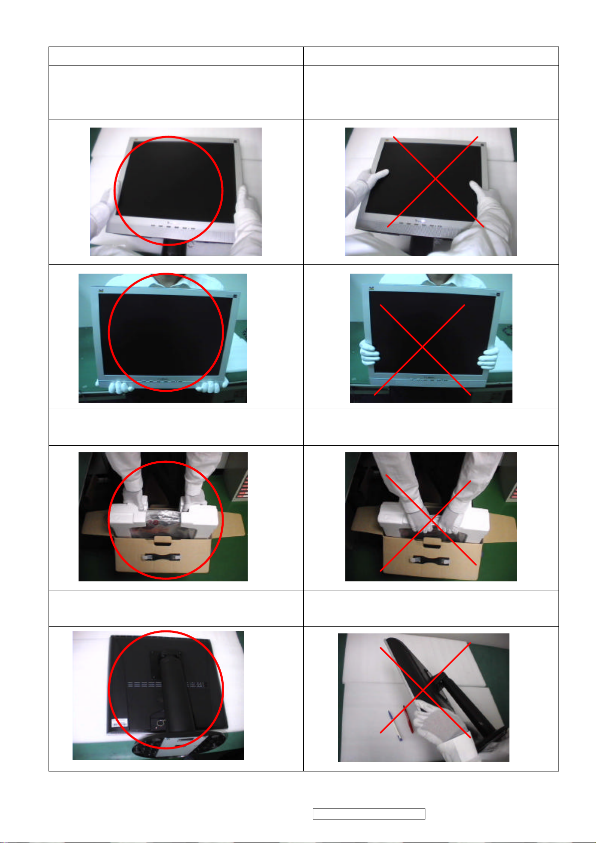
Correct methods : Incorrect Methods :
Only touch the metal-frame of the panel or the front cover of
the monitor.
Do not touch the surface of the polarizer .
Surface of the panel is pressed by fingers & this may cause
“ MURA “
Take out the monitor with cushion Take out the monitor by grasping the LCD panel.
That may cause “ MURA“.
Place the monitor on a clean & soft foam pad . Place the monitor on foreign objects .
That could scratch the surface of panel
3
ViewSonic Corporation Confidential - Do Not Copy VE920m-1_VE920mb-1
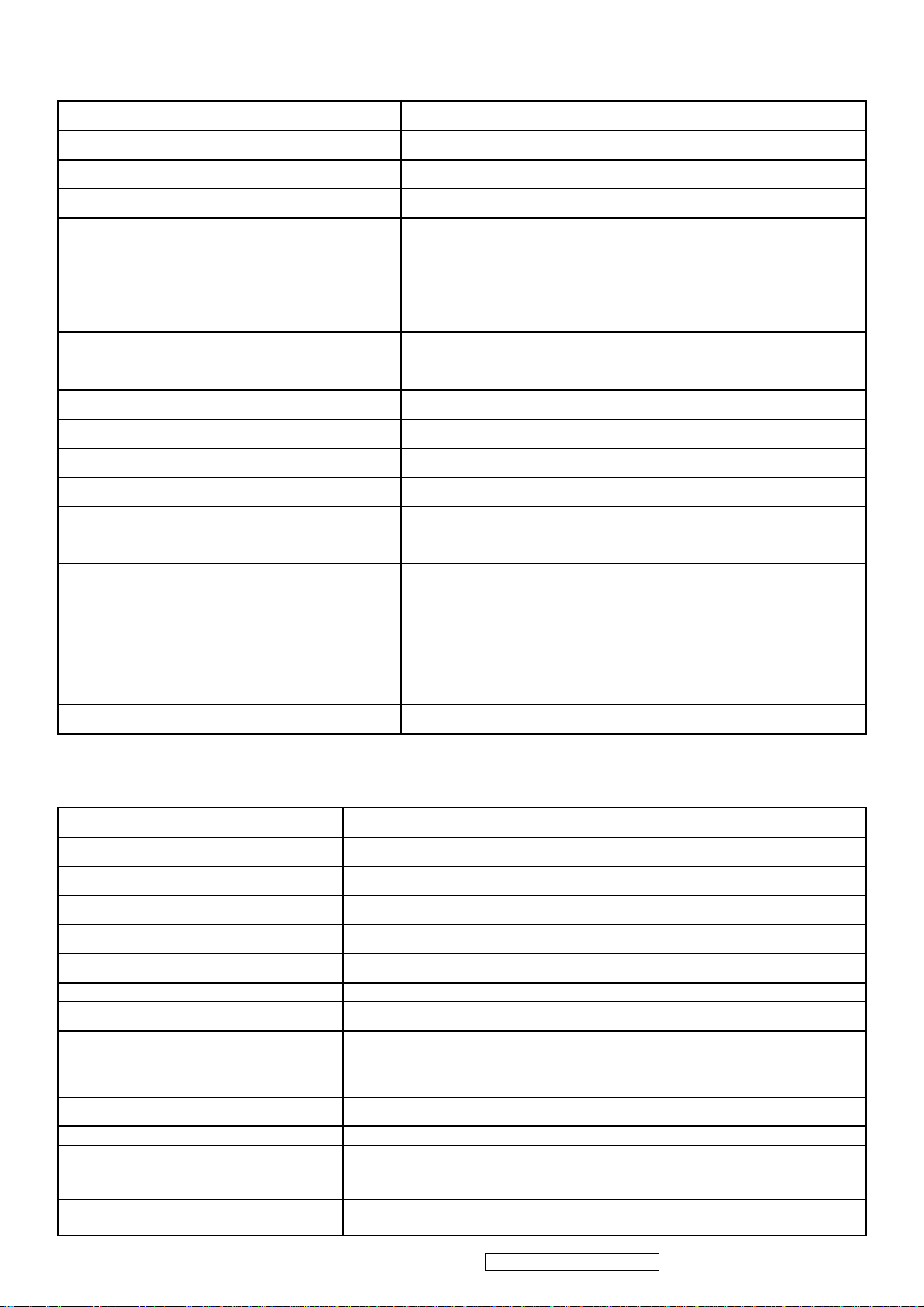
2. Specification
Introduction
FEATURES
Size 19”
Luminance (Typ, cd/㎡) 280 cd/㎡
Contrast Ratio (Typ) 450:1
TFTLCD PANEL
Input Signal
Sync Compatibility
Compatibility
Power Voltage AC 100-240V, 50/60Hz Yes
Power Consumption
Audio 1.2 W (audio), 2W*2 (speaker) Yes
Ergonomics
Colors ( 6 bit + 2 bit FRC) 16.2 M colors
Response Time (Typ) 8 ms
Viewing Angle (H/V) 150 ° / 130 °
Recommend resolution 1280x1024@60Hz
Analog (75ohms, 0.7/1.0 Vp-p) Yes
Digital Yes
Separate Sync Yes
Composite Sync No
Sync on Green No
PC Yes
Power Mac Yes
TV Box (NextVision 6) Yes
On Mode(Max / Typ) 58W
Active Off Mode (Max) 2W
Tilt (20 ° to -5 °) Yes
Swivel No
Pivot No
Height Adjust No
OSD Control
Dimension
Weight
Operating Condition
Storage Condition
Regulation
GENERAL specification
Test Resolution & Frequency 1280x1024 @ 60Hz
Test Image Size Full Size
Contrast and Brightness Controls
[X X] [ 1 ] [▼] [▲] [ 2 ] [ ]
Physical (W x H x D mm) 423 x 434 x 221 (mm)
Package (W x H x D mm) 474 x 475 x 184 (mm)
Physical (Net kg/lb) 5.2 kg / 11.5 lb
Package (Gross Kg/lb) 6.8 kg / 15.0 lb
Temperature (℉/℃) 41℉-95℉/+5℃-+35℃
Humidity (%) 20 % - 80 %
Temperature (℉/℃) -4℉-131℉/-20℃-55℃
Humidity (%) 20 % - 85 %
UL, cUL, FCC-B, CB, CE, NOM, TUV/GS, TUV ERGO (covers ISO13406-2 & MPRII),
TCO03, GOST-R + 20 ORIGINAL COPIES HYGIENIC, SASO, PCBC, VCCI, BSMI, CCC,
(PSB), (C-TICK), TUV -S, Green Mark, energy star
HYGIENIC, SASO, PCBC, VCCI, BSMI, CCC, (PSB), (C-TICK), TUV-S, Green Mark,
energy star
Factory Default:
Contrast = 70%, Brightness = 100%
Yes
16.7 x 17.1 x 8.7 (in)
17.6 x 18.7 x 7.2 (in)
ViewSonic Corporation Confidential - Do Not Copy VE920m-1_VE920mb-1
4
VIDEO INTERFACE
TEST WITH NO DAMAGE
Analog Input Connector DB-15 (Analog), refer the appendix A
Digital Input Connector N/A
Default Input Connector Defaults to the first detected input
Video Cable Strain Relief Equal to twice the weight of the monitor for five minutes
Video Cable Connector DB-15 Pin out Compliant DDC 2B
1. Video RGB (Analog)
Video Signals
Video Impedance 75 Ohms (Analog)
Maximum PC Video Signal 950 mV with no damage to monitor
Maximum Mac Video Signal 1250 mV with no damage to monitor
Sync Signals TTL
DDC 2B Compliant with Revision 1.3
Sync Compatibility Separate Sync
Video Compatibility
Resolution Compatibility
Exclusions Not compatible with interlaced video
2. DVI (Digital)
Separate
Shall be compatible with all PC type computers, Macintosh computers,
and after market video cards
640 x 350*, 640 x 480, 720 x 400* (640 x 400*), 800 x 600, 832 x 624,
1024 x 768, 1152 x 870, 1280 x 720, 1280 x 960, 1280 x 1024
* The image vertical size might not be full screen.
But the image vertical position should be at the center.
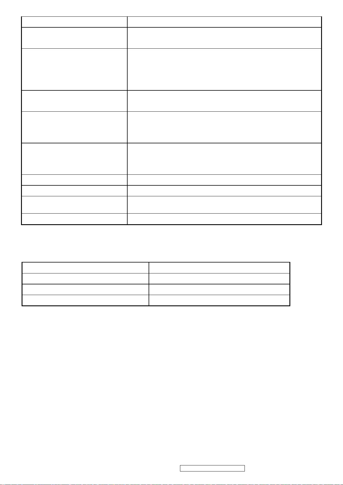
POWER SUPPLY
Power Supply (Adapter) Part Number: 27-D003115
Input Voltage Range
Input Frequency Range
Short Circuit Protection
Over Current Protection 3.3~4.5 A typical at 5 VDC
Leakage Current
Efficiency 80 % TYPICAL AT 115 VAC FULL LOAD
Fuse
Power Dissipation
Max Input AC Current
Inrush Current (Cold Start) 120A(MAX) @ 240VAC , 50HZ
Power Supply Cold Start
Power Supply Transient Immunity
100 to 240 VAC
50 to 60 Hertz
OUTPUT CAN BE SHORTED WITHOUT DAMAGE
3.5 MA (MAX) AT 254VAC / 60HZ
INTERNAL AND NOT USER REPLACEABLE
58 (Max) Watt
1.8 A RMS @ 100 VAC,
SHALL START AND FUNCTION PROPERLY WHEN UNDER FULL LOAD,
WITH ALL COMBINATIONS OF INPUT VOLTAGE, INPUT FREQUENCY,
AND OPERATING TEMPERATURE
SHALL BE ABLE TO WITHSTAND AN EN61000-4-4 ±2KV TRANSIENT
ViewSonic Corporation Confidential - Do Not Copy VE920m-1_VE920mb-1
5
Power Supply Line Surge Immunity Shall be able to withstand ±2KV (L-L) and ±2.3KV (L-PE) with no damage
Power Supply Missing Cycle Immunity
Power Supply Acoustics
US Type Power Cable
European Type Power Cable
CCC Type Power Cable
Power Saving Operation(Method) VESA DPMS Signaling
Shall be able to function properly, without reset or visible screen artifacts, when
½ cycle of AC power is randomly missing at nominal input
The power supply shall not produce audible noise that would be detectable by the
user. Audible shall defined to be in compliance with ISO 7779 (DIN
EN27779:1991) Noise measurements of machines acoustics. Power Switch noise
shall not be considered
Separate 3-prong NEMA 5-15P type plug. Length = 1.8m. Connects to display.
Color = Black
Schuko CEE7-7 type plug.
Length = 1.8m, Connects to display.
Color = Black
Separate 3-prong type plug.
Length = 1.8m. Connects to display.
Color = Black
Power Consumption
Recovery Time
ON Mode < 58 W (max)
ACTIVE OFF < 2 W
ON Mode = N/A, ACTIVE OFF < 3 sec
2.5 ELECTRICAL REQUIREMENT
Horizontal / Vertical Frequency
Horizontal Frequency
Vertical Refresh Rate
Maximum Pixel Clock 135 MHz (EDID file is 140MHz)
Sync Polarity Independent of sync polarity.
30 – 82 kHz
50 – 85* Hz.
ViewSonic Corporation Confidential - Do Not Copy VE920m-1_VE920mb-1
6
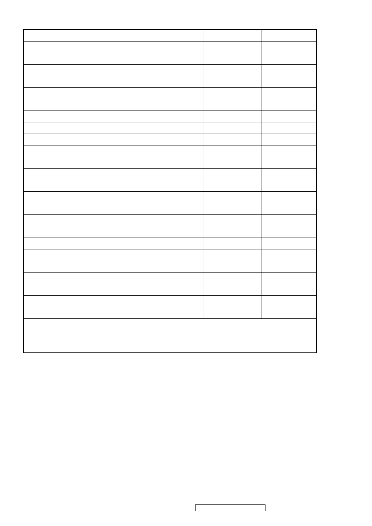
Timing Table
Item Timing Analog Digital
1 640 x 350 @ 70Hz, 31.5kHz Yes No
2 640 x 400 @ 60Hz, 31.5kHz Yes* No
3 640 x 400 @ 70Hz, 31.5kHz Yes No
4 640 x 480 @ 60Hz, 31.5kHz Yes No
5 640 x 480 @ 67Hz, 35.0kHz Yes No
6 640 x 480 @ 72Hz, 37.9kHz Yes No
7 640 x 480 @ 75Hz, 37.5kHz Yes No
8 640 x 480 @ 85Hz, 43.27kHz Yes No
9 720 x 400 @ 70Hz, 31.5kHz Yes No
10 800 x 600 @ 56Hz, 35.1kHz Yes No
11 800 x 600 @ 60Hz, 37.9kHz Yes No
12 800 x 600 @ 75Hz, 46.9kHz Yes No
13 800 x 600 @ 72Hz, 48.1kHz Yes No
14 800 x 600 @ 85Hz, 53.7kHz Yes No
15 832 x 624 @ 75Hz, 49.7kHz Yes No
16 1024 x 768 @ 60Hz, 48.4kHz Yes No
17 1024 x 768 @ 70Hz, 56.5kHz Yes No
18 1024 x 768 @ 72Hz, 58.1kHz Yes No
19 1024 x 768 @ 75Hz, 60.0kHz Yes No
20 1024 x 768 @ 85Hz, 68.67kHz Yes No
21 1152 x 870 @ 75Hz, 68.7kHz Yes No
22 1280 x 1024 @ 60Hz, 63.4kHz Yes No
23 1280 x 1024 @ 75Hz, 79.97kHz Yes No
24 1280x 720 @ 60Hz, 45kHz (HDTV) Yes No
Note 1:When Vertical frequency at 85Hz or resolution, the vertical image size might not be full screen. But the
vertical image position should be at the center.
Note2: *: The vertical image size might not be full screen.
Primary Presets
1280x1024 @ 60Hz
User Presets
Number of User Presets (recognized timings) Available: 10 presets total in FIFO configuration
Changing Modes
● Maximum Mode Change Blank Time for image stability : 3 seconds (Max), excluding “Auto Adjust” time
● Under DOS mode (640 x 350, 720 x 400 & 640 x 400), there is no “Auto Adjust” feature.
● The monitor needs to do “Auto Adjust” the first time a new mode is detected but except the DOS mode 640 x 350, 720 x
400 & 640 x 400.(see section “0-Touch™ Function Actions”)
● While running Change Mode, Auto Adjust or Memory Recall, the image shall blank
7
ViewSonic Corporation Confidential - Do Not Copy VE920m-1_VE920mb-1
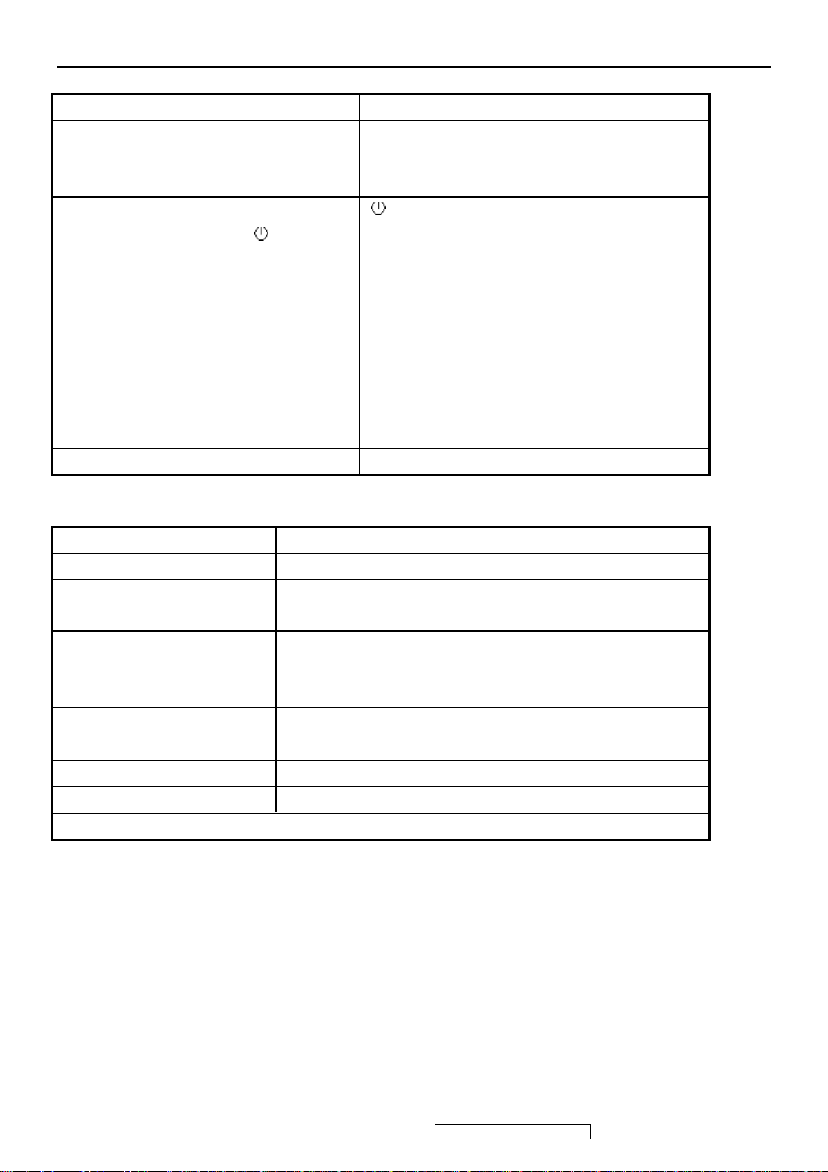
3. Front Panel Function Control Description
Front Panel Hardware Controls
Power Switch (Front Head) Power Control, soft Power Switch.
Power LED (Front Head) Green – ON
Orange – Active Off
Dark = Soft Power Switch OFF
Front Panel Controls (Head)
[XX] [ 1 ] [▲] [▼] [ 2 ] [ ]
Reaction Time OSD must fully appear within 0.5s after pushing Button 1
[ ] Power
[ 1 ] BUTTON 1
[ 2 ] Button 2
[ ] UP ARROW BUTTON
▲
[ ] DOWN ARROW BUTTON
▼
[XX] Audio Mute on/off
Note: Power Button, Button 1 and Button 2 and Mute
Button must be one-shot logic operation. (i.e. there should
be no cycling)
Short Cuts Function from the button(s)
[1]
[2]
[▼] or [▲]
Main Menu
Auto image adjust
To immediately activate Contrast menu. It should be change to Brightness
OSD by push button [2]
[▼] + [▲]
[1] + [2]
[1] + [▼] + [▲]
[1] + [▼]
[1] + [▲]
[XX]
Remark : All the short cuts function are only available while OSD off
Recall both of Contrast and Brightness to default
Toggle 720x400 and 640x400 mode when input 720x400 or 640x400
mode
White Balance. (Not shown on user’s guide)
Power Lock
OSD Lock
Audio Mute on /off
ViewSonic Corporation Confidential - Do Not Copy VE920m-1_VE920mb-1
8
Main Menu Controls
Auto Image Adjust*1
Contrast/Brightness*2*4
Audio Adjust
Volume*4, Mute*4
Color Adjust
sRGB, 9300K, 6500K(default), 5400, 5000, User Color [R, G, B]
Information
H Frequency, V Frequency, Resolution, Pixel Clock, Serial Number,
Model Number, “www.ViewSonic.com”
Manual Image Adjust
H. Size*1, H./V. Position*1, Fine Tune*1, Sharpness*3
Setup Menu
Language [English, French, German, Spanish, Italian, Finnish, Japanese, Traditional Chinese, Simplified
Chinese], Resolution Notice, OSD Position, OSD Timeout, OSD Background
Memory Recall
*1 These functions are not available in Digital Mode
*2 These functions are not available under sRGB Mode
*3 These functions are not available under Native Resolution Mode
*4 These functions setting can be recalled to default by [▼]+[▲]
[Remark] Please refer to the detail in the Appendix C
ViewSonic Corporation Confidential - Do Not Copy VE920m-1_VE920mb-1
9
Function descriptions
OSD Lock short cuts function for the buttons
The OSD lock will be activated by pressing the front panel control buttons "(1), & (▲)" for 10 seconds. If the user
then tries to access the OSD by pressing any of the buttons "1", "▼", "▲", "2" a message will appear on the screen
for 3 seconds showing "OSD Locked". The OSD lock will be deactivated by pressing the front panel control
buttons "(1), & (▲)" again for 10 seconds.
Note1: When the OSD is locked will lock all functions, including “Volume” and “Mute”
Note 2: Status bar indicating OSD Lock or Unlock is in progress and when complete it will indicate “OSD
Locked”
Note 3: OSD Lock should not lock Power Button and Power Lock function
Power Lock short cuts function for the buttons
The power button lock will be activated by pressing the front panel control buttons "(1), & (▼)" for 10 seconds.
Locking the power button means that the user won't be able to turn off the LCD while the power button is locked.
If the user presses the power button while it is locked, a message will appear on the screen for 3 seconds showing
"Power Button Locked". It also means that with the power button locked, the LCD would automatically turn back
"On" when power is restored after a power failure. If the power button is not in the locked mode, then power
should return to it's previous state when power is restored after a power failure. The power button lock will be
deactivated by pressing the front panel control buttons "(1), & (▼)" again for 10 seconds.
Note 1: Status bar indicating Power Button lock or unlock is in progress and when complete it will indicate
“Power Button Locked”
Note 2: Power should only be lockable in the “On State”
Memory Recall Actions
Memory Recall action on the analog and digital mode as below
1. Set the factory defaults as shown in Section 4-8
2. Clean all the mode setting buffer
3. Execute Auto Image Adjust
Note: Memory Recall should have no effect for Language, Power Lock, User Color Settings or Input Priority
Resolution Notice Actions
1. Resolution Notice OSD should show on screen after changing to non-native mode for 30 sec
2. The OSD should disappear after 10 sec or by pushing button [1] or [2]
Resolution Notice function should be disabled when push button [2] under Resolution Notice OSD
0-Touch™ Function Actions
1. Execute Auto Image Adjust when new mode detected, and save the settings to buffer for further use
2. It should be reset by Memory Recall function
(Should not reset by power off, power unplug and others)
OSD Auto Save
The OSD shall save new settings when it is turned off by the user or when it times out. There shall not be a
separate save
10
ViewSonic Corporation Confidential - Do Not Copy VE920m-1_VE920mb-1
AUDIO INTERFACE (SPEAKER SPECIFICATION)
Line input connection
Line input signal 1.0Vrms@1kHz
Line input impedance 10k ohm
Maximum power output (Electric)
Signal to Noise Ratio 72db
Frequency response F0 -20kHz (F0: Lowest resonant freq.)
Distortion <8% THD @1kHz
Vibration
3.5 mm stereo jack
2W
There should be no audible vibration with volume at
100%. (Input signal within 1 Vrms)
Screen image
Connector PC99 requirement Audio in
Cable type / length 3.5mm stereo cable / 1.8m length
Audio DPMS
There should be no affect on the screen image stability
under any conditions
Lime Green pantone # 577C
NOTE: THERE IS NO GUARANTEE <1 W POWER
CONSUMPTION IN ACTIVE OFF MODE, WHEN THE
AUDIO CABLE IS CONNECTED
ViewSonic Corporation Confidential - Do Not Copy VE920m-1_VE920mb-1
11
3. OSD Table
Layer 1 Layer 2 Layer 3
Auto Image Adjust
Contrast/Brightness
Audio Adjust
Color Adjust
Information
Manual Image Adjust
Contrast (+ / -)
Brightness (+ / -)
Volume (+ / -)
Mute On/Off
sRGB
9300K
6500K
5400K
5000K
User Color
Horizontal Size + / -
H/V Position
Red (+ / -)
Green (+ / -)
Blue (+ / -)
H Position (+ / -)
V Position (+ / -)
Setup Menu
Fine Tune + / Sharpness + / -
English
French
German
Spanish
Language Select
Resolution Notice On/Off
Input Priority On/Off
OSD Position
OSD Time Out 5/15/30/60
Italian
Finnish
Japanese
Simplified Chinese
Traditional Chinese
H Position (+ / -)
V Position (+ / -)
OSD Background On/Off
Memory Recall
12
ViewSonic Corporation Confidential - Do Not Copy VE920m-1_VE920mb-1
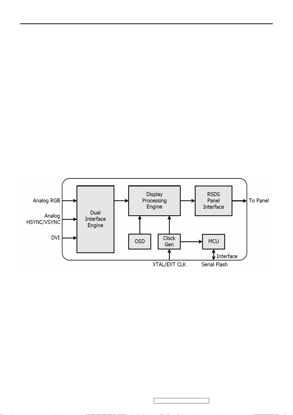
4. Circuit Description
The TSUM57AK is total solution graphics processing IC for LCD monitors with panel resolutions up to SXGA. It is
configured with a high-speed integrated triple-ADC/PLL, a high quality display processing engine, and an integrated output
display interface that can support RSDS panel interface format. To further reduce system costs, the TSUM57AK also
integrates intelligent power management control capability for green-mode requirements and spread- spectrum support for
EMI management.
The TSUM57AK incorporates the world’s first coherent oversampled RGB graphics ADC in a monitor controller system. The
oversampling ADC samples the input RGB signals at a frequency that is much higher than the signal source pixel rate. This
can preserve details in the video signal that ordinarily would be lost due to input signal jitter or bandwidth limitations in
non-oversampled systems. The TSUM57AK also incorporates a new Dynamic Frame Rate (DFR) generator for the digital
output video to the display panel that preserves the advantages of a fixed output clock rate, while eliminating the output end of
frame short-line.
ViewSonic Corporation Confidential - Do Not Copy VE920m-1_VE920mb-1
13
5. Adjustment Procedure
A. Function Test and Alignment Procedure
1. All Modes Reset
You should do “All Model Reset” (Refer to Chap 3. Hot Keys for Function Controls) first. This action will allow
you to erase all end-user’s settings and restore the factory defaults.
2. Auto Image Adjust
The Auto Adjust is aimed to offer a best screen quality by built-in ASIC. For optimum screen quality, the user
has to adjust each function manually.
A.Turn the computer and LCD monitor on.
B. Press the ‘Auto’ button on monitor keypad to Auto Adjust.
C. The LCD monitor will start the Auto Adjust process automatically and run for 10 consecutive seconds, during
which time you will notice the image change.
3. Firmware
Test Patten: Burn in Model (Refer to Chap3. Hot Keys for Function Control)
-Make sure the F/W is the latest version.
4. DCC
Test Patten: EDID program
-Make sure it can pass test program.
5. Window Shut Down
Test Signal: 1280*1024@60Hz
Test Pattern:
Checkered Pattern Every One Pixel (50%Green & 50%Blue)
Inspection Item: Flicker, Mura
6. Window BG
Test Signal: 1280*1024@60Hz
Test Pattern:
Window standard pattern
Inspection Item: Line Defect, Function Defect & Mura
7. 25 Gray
Test Signal: 1280*1024@60Hz
Test Pattern:
Full Screen 25% White (Gray)
Inspection Item: Particle, Line Defect & Mura
14
ViewSonic Corporation Confidential - Do Not Copy VE920m-1_VE920mb-1
8. 50 Gray
Test Signal: 1280*1024@60Hz
Test Pattern:
Full Screen 50% White (Gray)
Inspection Item: Bright Dot, Particle, Line Defect & Mura
9. White Box
Test Signal: 1280*1024@60Hz
Test Pattern:
Window standard pattern
Inspection Item: Particle, Line Defect, Power, Image Remain & Mura
10. Black Box
Test Signal: 1280*1024@60Hz
Test Pattern:
Window standard pattern
Inspection Item: Bright Dot, Line Defect & Power
11. RED
Test Signal: 1280*1024@60Hz
Test Pattern:
Full Screen Red
Inspection Item: Bright Dot, Partial & Line Defect
12. Green
Test Signal: 1280*1024@60Hz
Test Pattern:
Full Screen Green
Inspection Item: Bright Dot, Partial & Line Defect
13. Blue
Test Signal: 1280*1024@60Hz
Test Pattern:
Full Screen Green
Inspection Item: Bright Dot, Partial & Line Defect
14. Gray_Scale_0-100_V64
Test Signal: 1280*1024@60Hz
Test Pattern:
Vertical 64 (256) Gray Scale (Right → Left,From 0 to 100% White)
Inspection Item: Line Defect & Function Defect
15
ViewSonic Corporation Confidential - Do Not Copy VE920m-1_VE920mb-1
15. Function Test Display pattern
Item
1
2
3
4
5
6
7
8
Pattern Description Remark
Gray_Scale_0-100_V
Gray_Scale_0-100_H
Black Full Screen Black Figure 3
Red Full Screen 50% Red Figure 4
Green Full Screen 50% Green Figure 5
Blue Full Screen 50% Blue Figure6
White Full Screen White Figure7
Black_Tile Black Tile Under White Background Figure 8
Vertical 64 (256) Gray Scale (右→左,From 0 to 100% White)
Horizontal 64 (256) Gray Scale (上→下,From 0 to 100% White)
Figure 1
Figure 2
ViewSonic Corporation Confidential - Do Not Copy VE920m-1_VE920mb-1
16
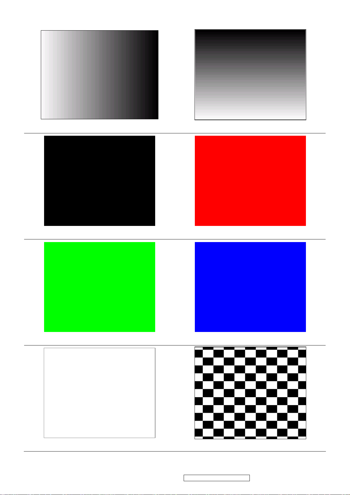
Figure 1 Figure 2
Figure 3 Figure 4
Figure 5 Figure 6
Figure 7 Figure 8
ViewSonic Corporation Confidential - Do Not Copy VE920m-1_VE920mb-1
17
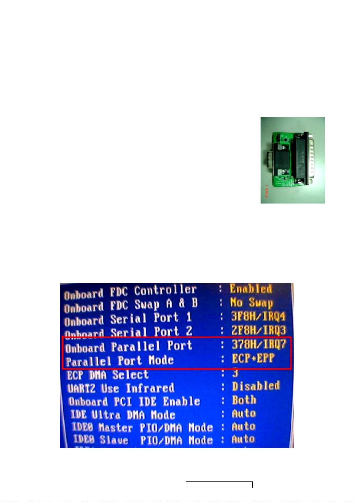
BIOS update procedure
1. To setup ISP environment
Hardware:
PC or Notebook , Parallel(Printer) cable , ISP tool( Fig 1)
Software:
ISP driver .
If the O.S. was Win2000 or Win XP please have to install
PORT95NT.exe
In order to ensure can execute ISP program, please set BIOS in PC or Notebook as Fig 2
Fig1
Fig 2
18
ViewSonic Corporation Confidential - Do Not Copy VE920m-1_VE920mb-1
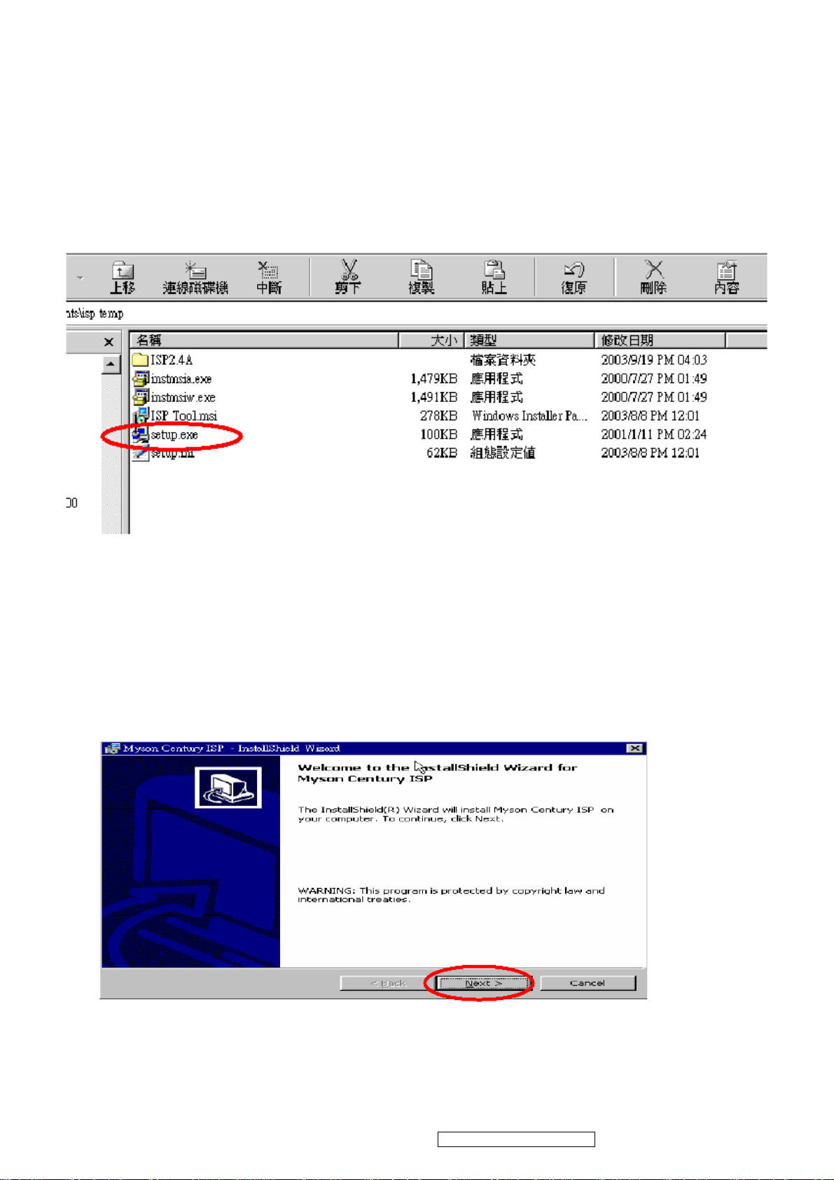
2. Install ISP
2.1 User could download ISP driver and PORT95NT install file from Myson Century
website( //www.myson.com.tw )
2.2 After extracting the zip file, the total files list as Fig 2.2, and double click the file of setup.exe
to install.
2.3 Press “Next” button to continue., see Fig 2.3
Fig 2.2
Fig 2.3
ViewSonic Corporation Confidential - Do Not Copy VE920m-1_VE920mb-1
19
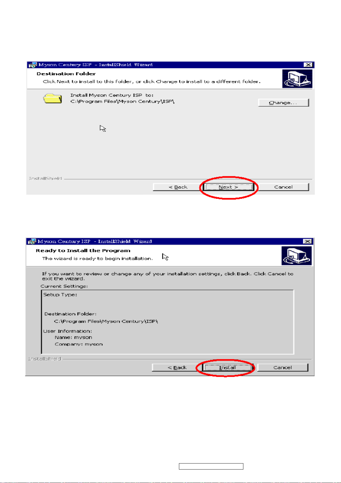
2.4 Keep default setting or press “Change” button for selecting the path that you want , and then press“Next”button to
continue, see Fig 2.4.
2.5 Press “Install” button to continue, see Fig 2.5
Fig 2.4
Fig 2.5
20
ViewSonic Corporation Confidential - Do Not Copy VE920m-1_VE920mb-1
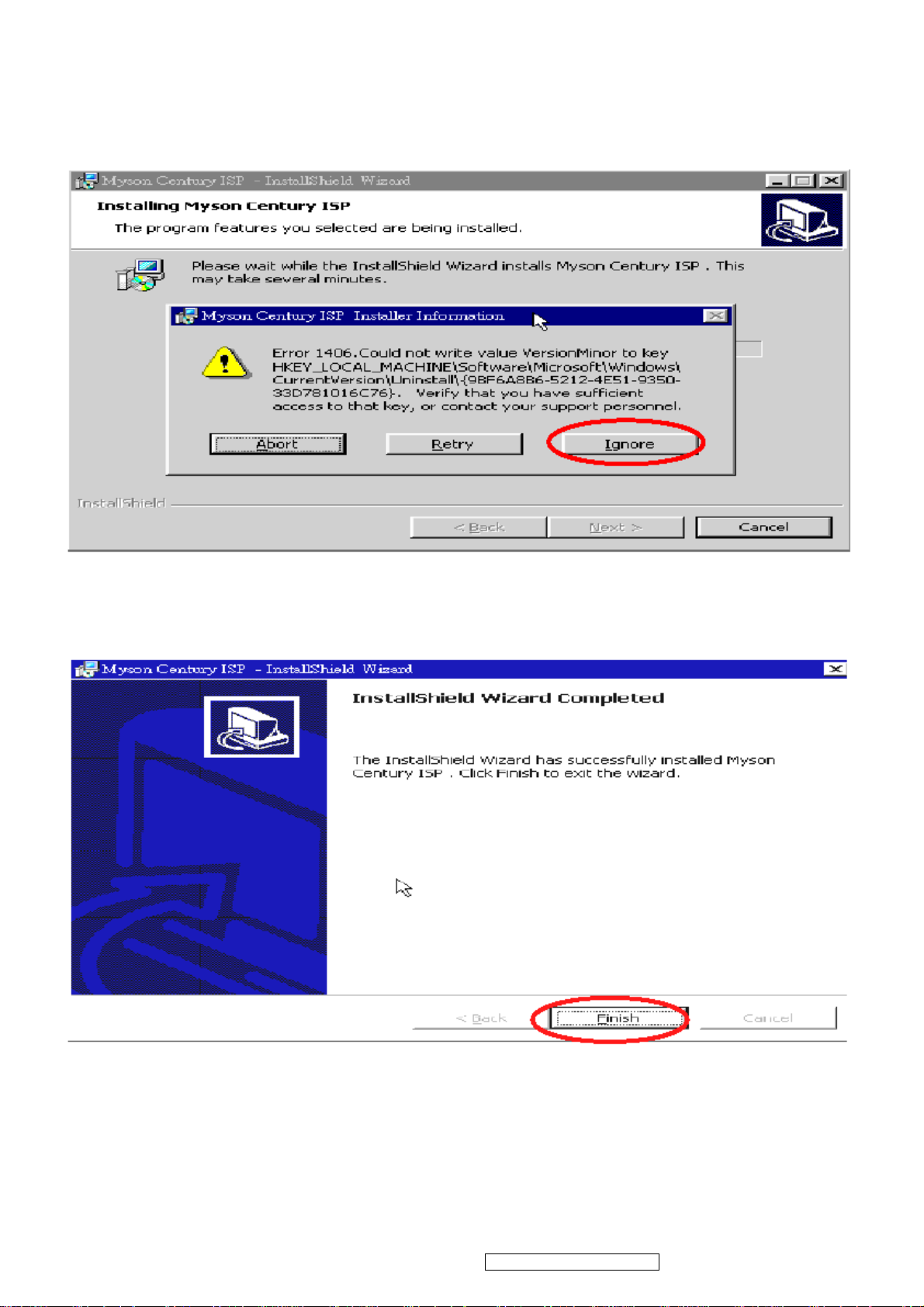
2.6 The Installer Information shows package warning, press “Ignore” button to continue, see Fig 2.6.
Fig 2.6
2.7 Installation has finished, press “Finish” button, see Fig 2.7.
Fig 2.7
ViewSonic Corporation Confidential - Do Not Copy VE920m-1_VE920mb-1
21
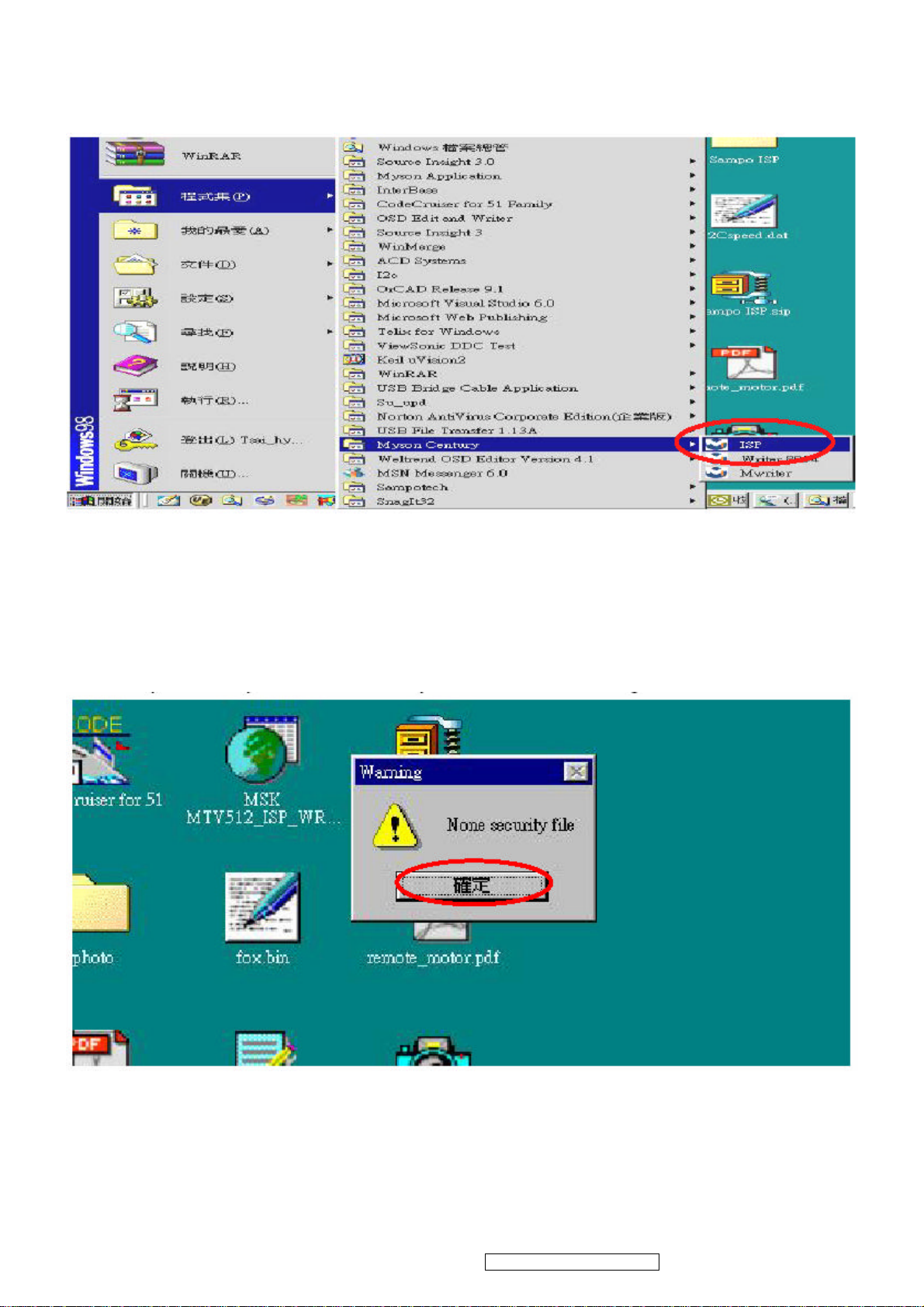
3. ISP security code
3.1 After installation, we could find the shortcut in the setting path or the program bar (default setting), see Fig 3.1.
Fig 3.1
2.2 Security file is a key to use ISP function, press “確定” button, see Fig 3.2.
Fig 3.2
22
ViewSonic Corporation Confidential - Do Not Copy VE920m-1_VE920mb-1
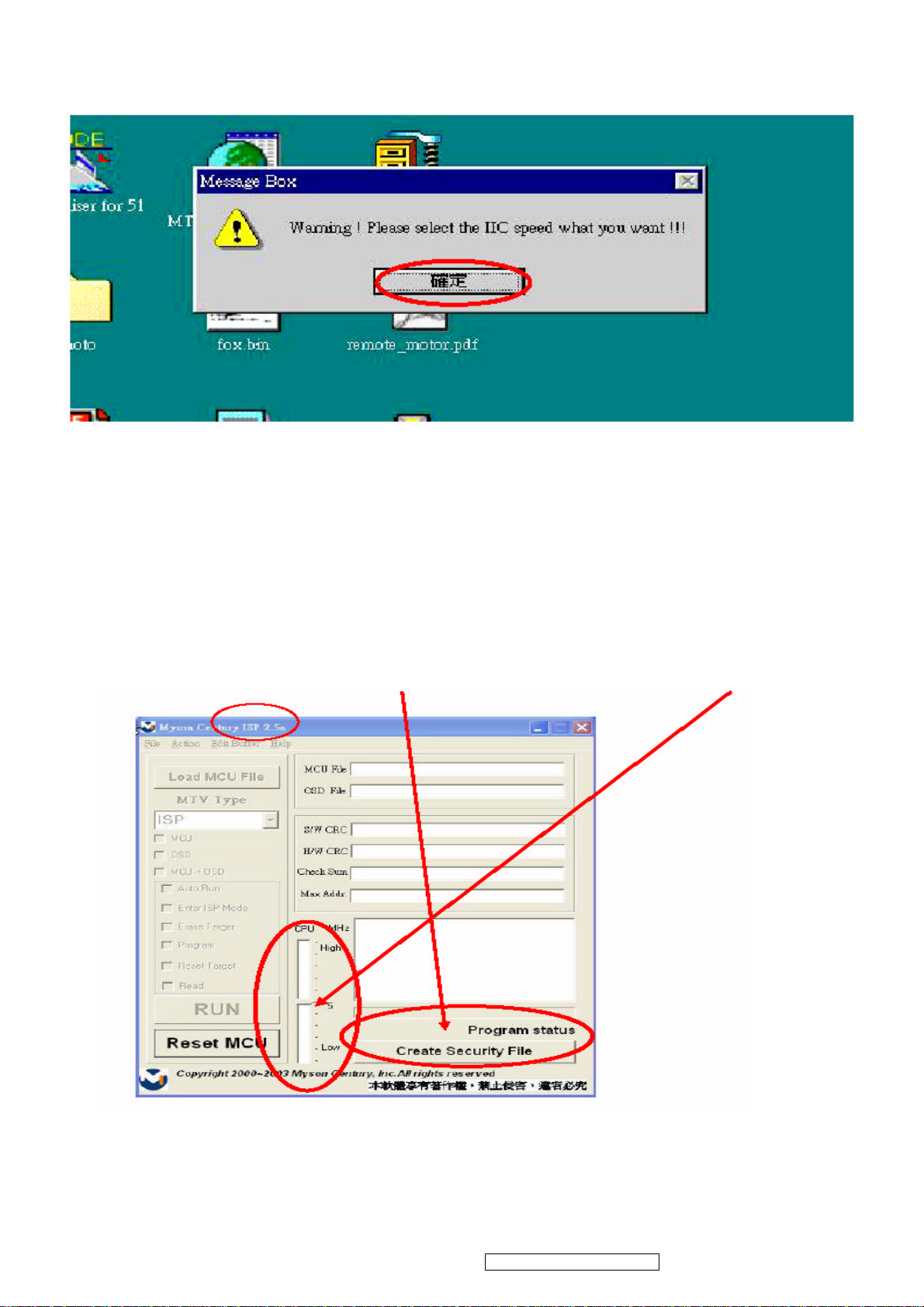
3.3 The warning is used to remind user of that different CPU rate may cause ISP function fail(it is limited by IIC protocol),
press “確定” button, see Fig 3.3.
Fig 3.3
2.4 Press“Create Security File” button to key in security code. Adjusting bar to decrease speed of IIC bus, see Fig 3.4.
Fig 3.4
ViewSonic Corporation Confidential - Do Not Copy VE920m-1_VE920mb-1
23
 Loading...