

Page 1

Service Manual
ViewSonic VA1703w-1
VA1703wb-1
Model No. VS11534
17” Color TFT LCD Display
(VA1703w-1_VA1703wb-1_SM Rev. 1a Nov. 2006)
ViewSonic 381 Brea Canyon Road, Walnut, California 91789 USA - (800) 888-8583
Page 2
Copyright
Copyright © 2006 by ViewSonic Corporation. All rights reserved. No part of this publication
may be reproduced, transmitted, transcribed, stored in a retrieval system, or translated into any
language or computer language, in any form or by any means, electronic, mechanical, magnetic,
optical, chemical, manual or otherwise, without the prior written permission of ViewSonic
Corporation.
Disclaimer
ViewSonic makes no representations or warranties, either expressed or implied, with respect to
the contents hereof and specifically disclaims any warranty of merchantability or fitness for any
particular purpose. Further, ViewSonic reserves the right to revise this publication and to make
changes from time to time in the contents hereof without obligation of ViewSonic to notify any
person of such revision or changes.
Trademarks
Optiquest is a registered trademark of ViewSonic Corporation.
ViewSonic is a registered trademark of ViewSonic Corporation.
All other trademarks used within this document are the property of their respective owners.
Revision History
Revision SM Editing Date ECR Number Description of Changes Editor
1a 11/29/2006 Initial Release Jamie Chang
i
ViewSonic Corporation Confidential - Do Not Copy VA1703w-1_VA1703wb-1
Page 3
TABLE OF CONTENTS
1. Precautions and Safety Notices 1
2. Specification 4
3. Front Panel Function Control Description 12
4. Circuit Description 18
5. Adjustment Procedure 19
6. Troubleshooting Flow Chart 37
7. Block Diagram 39
8. Schematic Diagrams 40
9. PCB Layout Diagrams 48
10. Exploded Diagram and Exploded Parts List 52
11. Recommended Spare Parts List 56
ii
ViewSonic Corporation Confidential - Do Not Copy VA1703w-1_VA1703wb-1
Page 4

1. Precautions and Safety Notices
1-1. Appropriate Operation
(1) Turn off the product before cleaning.
(2) Use only a dry soft cloth when cleaning the LCD panel surface.
(3) Use a soft cloth soaked with mild detergent to clean the display housing.
(4) Disconnect the power plug from AC outlet if the product is not used for a long period of
time.
(5) If smoke, abnormal noise, or strange odor is present, immediately switch the LCD
display off.
(6) Do not touch the LCD panel surface with sharp or hard objects.
(7) Do not place heavy objects on the LCD display, video cable, or power cord.
(8) Do not use abrasive cleaners, waxes or solvents for your cleaning.
(9) Do not operate the product under the following conditions:
- Extremely hot, cold or humid environment.
- Areas susceptible to excessive dust and dirt.
- Near any appliance generating a strong magnetic field.
- Place in direct sunlight.
1-2. Caution
No modification of any circuit should be attempted. Service work should only be
performed after you are thoroughly familiar with all of the following safety checks and
servicing guidelines.
1-3. Safety Check
Care should be taken while servicing this LCD display. Because of the high voltage
used in the inverter circuit, the voltage is exposed in such areas as the associated
transformer circuits.
1-4. Power Supply Requirements
The external AC power operating range shall be from 90 to 264Vac
1-5. LCD Module Handling Precautions
1-5-1. Handling Precautions
(1) Since front polarizer is easily damaged, pay attention not to scratch it.
(2) Be sure to turn off power supply when inserting or disconnecting from input
connector.
(3) Wipe off water drop immediately. Long contact with water may cause discoloration or
spots.
(4) When the panel surface is soiled, wipe it with absorbent cotton or other soft cloth.
(5) Since the panel is made of glass, it may break or crack if dropped or bumped on hard
surface.
(6) Since CMOS LSI is used in this module, take care of static electricity and insure
1
ViewSonic Corporation Confidential - Do Not Copy VA1703w-1_VA1703wb-1
Page 5

human earth when handling.
(7) Do not open nor modify the Module Assembly.
(8) Do not press the reflector sheet at the back of the module to any directions.
(9) In case if a Module has to be put back into the packing container slot after once it was
taken out from the container, do not press the center of the CCFL Reflector edge.
Instead, press at the far ends of the CFL Reflector edge softly. Otherwise the TFT
Module may be damaged.
(10) At the insertion or removal of the Signal Interface Connector, be sure not to rotate nor
tilt the Interface Connector of the TFT Module.
(11) After installation of the TFT Module into an enclosure (LCD monitor housing, for
example),
do not twist nor bend the TFT Module even momentary. At designing the enclosure, it
should be taken into consideration that no bending/twisting forces are applied to the
TFT Module from outside. Otherwise the TFT Module may be damaged.
(12) Cold cathode fluorescent lamp in LCD contains a small amount of mercury. Please
follow local ordinances or regulations for disposal.
(13) Small amount of materials having no flammability grade is used in the LCD module.
The LCD module should be supplied by power complied with requirements of Limited
Power Source, or be applied exemption.
(14) The LCD module is designed so that the CFL in it is supplied by Limited Current
Circuit.
Do not connect the CFL in Hazardous Voltage Circuit.
2
ViewSonic Corporation Confidential - Do Not Copy VA1703w-1_VA1703wb-1
Page 6
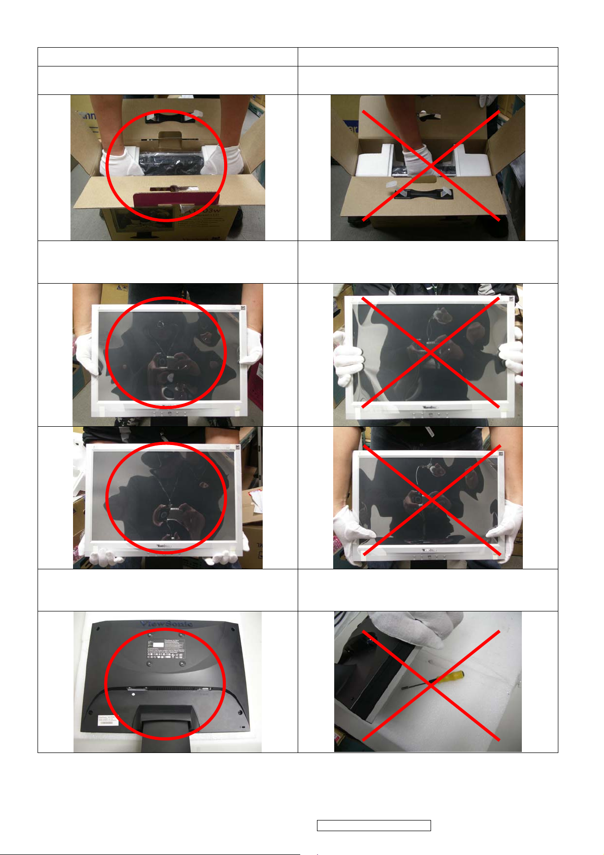
1-5-2. Handling and Placing Methods
Correct Methods: Incorrect Methods:
1.Take out the monitor with cushions 1.Taking out the monitor by grasping the LCD
panel. That may cause ”Mura”
2.Only touch the metal frame of the LCD panel
or the front cover of the monitor. Do not
touch the surface of the polarizer.
2.Surface of the LCD panel is pressed by
fingers and that may cause ”Mura”.
3.Place the monitor on a clean and soft foam
pad.
3.Placing the monitor on foreign objects. That
could scratch the surface of the panel or
cause “Mura”.
3
ViewSonic Corporation Confidential - Do Not Copy VA1703w-1_VA1703wb-1
Page 7
2. Specification
A
Product definition and specification
Product Name VA1703w/wb-1
Model Number VS11534
English, French, German, Italian, Spanish, Finnish,
OSD Languages
TFT LCD Panel and Model # HSD 170MGW1-A
Scalar MST TSUM56AK-1
Input Signal Analog x1
Sync Compatibility Separate Sync
Adapter Internal Power Board
Power Cable
nalog Cable (1.8 m, black), with PC 2001 and Hot Plug
Japanese, Traditional Chinese, Simplified Chinese,
Russian
Yes,
refer to APPENDIX B: Power Cable
Yes
Detect &DDC
DVI-D Cable(1.8m, black) with PC 2001 No
Audio Cable(1.8m, black) with PC 2001 NO
MIC Cable(1.8m, black) with PC 2001 No
USB Cable (V2.0) No
ViewSonic CD Wizard
ViewSonic Quick Start Guide
PerfectSuite CD No
Screen Protector Mylar Yes
Foot Protector plastic No
Service Insert For Region code = M units only
Response Time Sticker For Region code = M/E/U/G units only
Energy Star Sticker Yes
Warranty Sticker For Region code = G units only
Arabic, English, Finnish, Spanish, German, Italian,
Japanese, Swedish, Polish, Korean, Portuguese, Russian,
Turkish , French, Czech, Hungarian, Simplified Chinese,
Traditional Chinese
(Detached cable; refer the Appendix A)
Warranty Card For Region code = G units only
Warranty Carton Sticker For Region code = G units only
PE bag of Carton For Region code = G units only
4
ViewSonic Corporation Confidential - Do Not Copy VA1703w-1_VA1703wb-1
Page 8
1 GENERAL specification
Test Resolution & Frequency 1440x900 @ 60Hz
Test Image Size Full Size
Contrast and Brightness Controls
Factory Default:
Contrast = 70%, Brightness = 100%
2 VIDEO INTERFACE
Input Connector (refer the Appendix A) Analog = DB-15
Default Input Connector Defaults to the first detected input
Video Cable Strain Relief Equal to twice the weight of the monitor for five minutes
Video Cable Connector Pin out Refer to Appendix A; Compliant DDC/2B
Video Signals
Video Impedance 75 Ohms (Analog),
Maximum PC Video Signal 950 mV with no damage to monitor
Maximum Mac Video Signal 1250 mV with no damage to monitor
Sync Signals TTL
DDC 2B Compliant with Revision 1.3
Sync Compatibility Separate Sync
Video RGB (Analog)
Separate Sync
Video Compatibility
Resolution Compatibility Refer to Segment 4-5
Exclusions Not compatible with interlaced video
Shall be compatible with all PC type computers, Macintosh
computers, and after market video cards
3 USB INTERFACE
No USB interface
5
ViewSonic Corporation Confidential - Do Not Copy VA1703w-1_VA1703wb-1
Page 9
4 POWER SUPPLY
Internal Power Supply Part Number FSP032-2P101 / Delta DAC-12M051
Input Voltage Range 90 to 264 VAC
Input Frequency Range 47 to 63 Hertz
Short Circuit Protection Output can be shorted without damage
Over Current Protection 6.0 A typical at 5 VDC
Leakage Current 0.75mA (Max) at 264VAC / 50Hz
Efficiency (at 115VAC Full Load)
Fuse Internal and not user replaceable
Power Output 33 Watts (typ)
Ripple and Noise
Max Input AC Current 1.3 Arms @ 90VAC, 0.65 Arms @264VAC
Inrush Current (Cold Start) 60 A (max) @ 110VAC
Power Supply Cold Start
Power Supply Transient Immunity
Power Supply Line Surge Immunity
Power Supply Missing Cycle Immunity
75% TYPICAL AT 115VAC FULL LOAD
Ripple: <3%
Noise: <1%
Shall start and function properly when under full load, with all
combinations of input voltage, input frequency, and operating
temperature.
Shall be able to withstand an ANSI/IEEE C62.41-1980 6000V 200
ampere ring wave transient test with no damage.
Shall be able to withstand 1.5 times nominal line voltage for one
cycle with no damage.
Shall be able to function properly, without reset or visible screen
artifacts, when ½ cycle of AC power is randomly missing at
nominal input.
The power supply shall not produce audible noise that would be
detectable by the user. Audible shall defined to be in
Power Supply Acoustics
Power Saving Operation(Method) VESA DPMS Signaling
Power Consumption
Recovery Time On Mode = N/A, Active Off < 3 sec
compliance with ISO 7779 (DIN EN27779:1991) Noise
measurements of machines acoustics. Power Switch noise shall
not be considered.
Mode LED
On Green 21W (Typ) / 25W
Active off Amber <2W
Off Off <1W
Power
Consumption
(max)
6
ViewSonic Corporation Confidential - Do Not Copy VA1703w-1_VA1703wb-1
Page 10
5 ELECTRICAL REQUIREMENT
Horizontal / Vertical Frequency
Horizontal Frequency
Vertical Refresh Rate
24 – 70 kHz
50 – 75 Hz
Maximum Pixel Clock 135 MHz
Sync Polarity Independent of sync polarity
Timing Table
Digital - TMDS
SOG
DMT
DMT
For MAC
DMT
DMT
DTV
DTV
DMT
DMT
DMT
DMT
MAC
DMT
DMT
DMT
DMT
For MAC
For SUN
DTV
DTV
DMT;
DMT;
DMT
DMT
DMT
DMT
DMT
Item Timing
1 640 x 350 @ 70 Hz, 31.5 KHz
2 640 x 400 @ 60 Hz, 31.5 KHz
3 640 x 400 @ 70 Hz, 31.5 KHz
4 640 x 480 @ 50 Hz, 24.7 KHz
5 640 x 480 @ 60 Hz, 31.5 KHz
6 640 x 480 @ 67 Hz, 35 KHz
7 640 x 480 @ 72 Hz, 37.9 KHz
8 640 x 480 @ 75 Hz, 37.5 KHz
9 720 x 400 @ 70 Hz, 31.5 KHz
10 720 x 480 @ 60 Hz, 31.5 KHz
11 720 x 576 @ 50 Hz, 31.3 KHz
12 800 x 600 @ 56 Hz, 35.1 KHz
13 800 x 600 @ 60 Hz, 37.9 KHz
14 800 x 600 @ 72 Hz, 48.1 KHz
15 800 x 600 @ 75 Hz, 46.9 KHz
16 832 x 624 @ 75 Hz, 49.7 KHz
17 1024 x 768 @ 50 Hz, 39.6 KHz
18 1024 x 768 @ 60 Hz, 48.4 KHz
19 1024 x 768 @ 70 Hz, 56.5 KHz
21 1024 x 768 @ 75 Hz, 60 KHz
23 1152 x 864 @ 75 Hz, 67.5 KHz
24 1152 x 870 @ 75 Hz, 68.7 KHz
25 1152 x 900 @ 67 Hz, 62.5 KHz
26 1280 x 720 @ 50 Hz, 37.5 KHz
27 1280 x 720 @ 60 Hz, 45 KHz
28 1280 x 768 @ 50 Hz, 39.6 KHz
29 1280 x 768 @ 60 Hz, 47.8 KHz
30 1280 x 768 @ 75 Hz, 60.3 KHz
31 1280 x 960 @ 50 Hz, 49.4 KHz
32 1280 x 960 @ 60 Hz, 59.7 KHz
33 1280 x 960 @ 75 Hz, 75.2 KHz
34 1280 x 1024 @ 50 Hz, 52.7 KHz
35 1280 x 1024 @ 60 Hz, 64 KHz
36 1280 x 1024 @ 75 Hz, 80 KHz
37 1440 x 900 @ 60 Hz 55.9 KHz
38 1440 x 900 @ 75 HZ 70.6 KHz
*1. Tolerance ≧ ±2KHz (if no overlapping issue)
Analog
Composite
Separated
Remark
*2. Any timing not in the list, it should display as normal or show on “OUT OF RANGE” OSD message without
blanking.
*3. The image quality of 85Hz mode might be worse than 75Hz.
*4. The image quality 1280x960@75HZ and 1280x1024@75Hz mode might be worse than other mode.
7
ViewSonic Corporation Confidential - Do Not Copy VA1703w-1_VA1703wb-1
Page 11
7 AUDIO INTERFACE (SPEAKER SPECIFICATION)
No USB interface
8 TFT LCD PANEL
Panel Characteristics :
1st Source Panel
Model number HSD 170MGW1-A
Type Active Matrix TFT, TN technology
Active Size 17” Wide (367.2mm x 229.5mm)
Pixel Arrangement RGB Vertical Stripe
Pixel Pitch 0.255 mm
Glass Treatment Anti-Glare, Hard coating (3H)
# of Backlights 4 CCFL
Backlight Life 40000 Hrs (Typ) @7.5mA
250 cd/m2 (Typ after 30 minute warm up) @8.0mA Luminance (Center) –
CT = 6500K,
Contrast/ Brightness = Max
200 cd/m2 (Min after 30 minute warm up) @8.0mA
Brightness Uniformity (13 points) 75% (Typ) / 70 % (Min)
Contrast Ratio 500 :1 (Typ)
400 : 1 (Min)
Color Depth 262144 colors (6bit panel)
Horizontal Viewing Angle 140 degrees (Typ) / 130 degrees (Min) @ CR>10
Vertical Viewing Angle 130 degrees (Typ) / 120 degrees (Min) @ CR>10
Response Time
On-Off
10%-90% @ Ta=25°C 8ms (Typ) / 12 ms (Max)
Mercury 3.0 mg per lamp
Panel Defects Please see Panel Quality Specifications.
*Over 50% units of shipment shall be equal or better than the Typical value above.
8
ViewSonic Corporation Confidential - Do Not Copy VA1703w-1_VA1703wb-1
Page 12
9 IMAGE PERFORMANCE
Display Size
Horizontal Display Size, Primary Preset Full Screen
Vertical Display Size, Primary Preset Full Screen
Luminance
Lv (Max) –Condition:
Brightness / Contrast = 100%
CCT = USER COLOR (R/G/B=100%)
Lv (Def) –Condition:
Brightness / Contrast = 100%
Color Temperature = 6500K / sRGB
Lv (sRGB/6500K) –Condition:
Brightness / Contrast = Default
CCT = 6500K / sRGB
Lv (9300K) –Condition:
Brightness / Contrast = Default
CCT = 9300K
Lv (5400K) –Condition:
Brightness / Contrast = Default
CCT = 5400K
Lv (Brightness) –Condition:
Contrast = 100%
Lv (Max) = The Luminance requirement of section 6
“TFT LCD PANEL”
Lv (Def) / Lv (Max) x 100% > 93%
Lv (sRGB/6500K) / Lv (Max) x 100% > 85%
Lv (9300K) / Lv (Max) x 100% >65%
Lv (5400K) / Lv (Max) x 100% > 72%
Lv(Brightness=0%) / Lv(Brightness=100%) x 100% ≤ 55%
Lv (Contrast) –Condition:
Brightness = 100%
Lv(Contrast=0%) / Lv(Contrast=100%) x 100% ≤ 35%
9
ViewSonic Corporation Confidential - Do Not Copy VA1703w-1_VA1703wb-1
Page 13
Contrast Ratio
CR(Max) –Condition:
Same as the Contrast Ratio in section 6 “TFT LCD
Contrast / Brightness = 100%
PANEL ”
CCT = USER COLOR (R/G/B=100%)
CR(6500K) –Condition:
Contrast / Brightness = Default
CCT = 6500K
* ≧50% units of shipment shall be equal or better than typical CR spec.
CR(6500K) / CR(Max) ≧ 85%
Saturation
Contrast = Default
Brightness = Default
NO VISIBLE SATURATION
Test pattern = 6gray
Contrast = 100%
Brightness = 100%
12~16 - LEVEL SATURATION
Test pattern = 6gray
Preset Color Temperatures
sRGB It should meet IEC 61966-2-1 (1999-10) standard.
Preset 1
CCT (typ) = 9300K (u’CCT=0.1888; v’ CCT=0.4457)
CCT (max) = 10250K, CCT (min) = 8500K
Δu’v’<0.01 (@ Full White pattern)
Preset 2 (Primary)
CCT (typ) = 6500K (u’CCT=0.1978; v’ CCT=0.4684)
CCT (max) = 6950K, CCT (min) = 6100K
Δu’v’<0.01 (@ Full White pattern)
Preset 3
CCT (typ) = 5400K (u’CCT=0.2044; v’ CCT=0.4808)
CCT (max) = 6185K, CCT (min) = 4935K
Δu’v’<0.01 (@ Full White pattern)
Preset Color Temperature
Adjustability
* Any gray level and Contrast/Brightness should not get reddish, greenish or bluish.
Each color preset shall be adjustable. Red, Green, and Blue
shall be individually controlled.
10
ViewSonic Corporation Confidential - Do Not Copy VA1703w-1_VA1703wb-1
Page 14
10 MECHANICAL
Dimension (Desktop)
Width 406.7 mm (16.01 inch)
Height (Height adjust to the bottom) 374.9mm (14.75 inch)
Depth 210.17mm (8.27 inch)
Monitor Weight 3.7 Kg (8.2 lbs)
*Refer to Figure 1
Dimension (Head Only / Wall Mount)
Width 406.7 mm (16.01 inch)
Height 293.3mm (11.54 inch)
Depth 63mm (2.48 inch)
Monitor Weight 2.9 Kg (6.38 lbs)
*Refer to Figure 1
Ergonomics
Tilt Up
≧ 20º
Tilt Down From 0º down to -3º ~ -5º
Swivel Right
Swivel Left
N/A
N/A
Height Adjust N/A
11
ViewSonic Corporation Confidential - Do Not Copy VA1703w-1_VA1703wb-1
Page 15
3. Front Panel Function Control Description
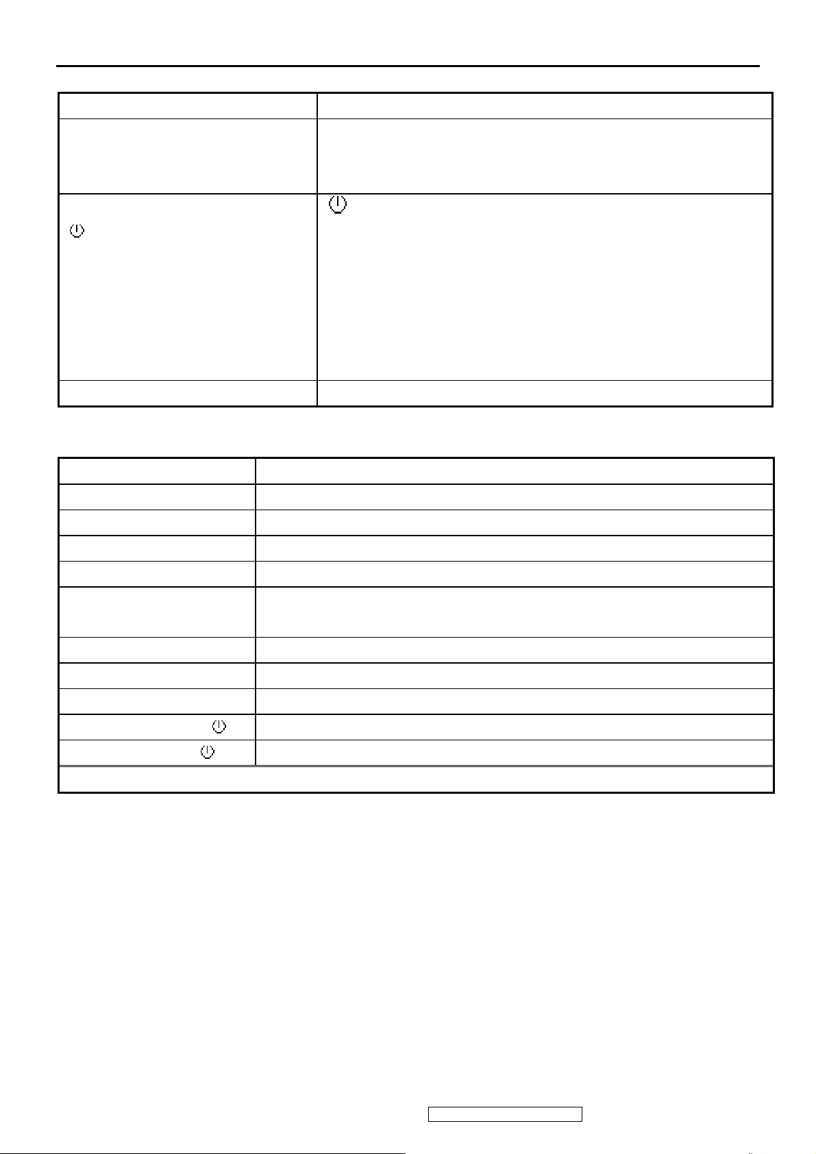
3-1. Front Panel Hardware Controls
Power Switch (Front Head) Power Control, soft Power Switch.
Power LED (Front Head) Green – ON
Orange – Power Saving Mode
Dark = Soft Power Switch OFF
Front Panel Controls (Head)
[ ] [ 1 ] [ 2 ] [▲] [▼]
Reaction Time OSD must fully appear within 0.5s after pushing Button 1
3-2. Short Cuts Function from the button(s)
[1] Main Menu
[2] Input toggle (Analog or Digital; refer to Appendix D)
[▼] Brightness adjust
[▲] Contrast adjust
[▼]+ [▲] Recall both of Contrast and Brightness to default
[1] + [2] Toggle 720x400 and 640x400 mode when input 720x400 or 640x400
[ ] Power
[ 1 ] Button 1
[ 2 ] Button 2
[▲] Up arrow button
[▼] Down arrow button
Note: Power Button, Button 1 and Button 2 must be one-shot
logic operation. (i.e. there should be no cycling)
mode
[1] + [▼] + [▲] White Balance. (Not shown on user’s guide)
[1] + [▼] Power Lock
[1] + [▲] OSD Lock
No signal + [2] + [ ] Burning mode
Signal + [2] + [ ] Factory Mode
Remark : All the short cuts function are only available while OSD off
12
ViewSonic Corporation Confidential - Do Not Copy VA1703w-1_VA1703wb-1
Page 16
3-3. Function descriptions
Main Menu Controls
The Main Menu OSD includes most of control functions.
Please refer to APPENDIX C (Main Menu OSD Table) for the detail.
OSD Lock short cuts function for the buttons
The OSD lock will be activated by pressing the front panel control buttons "(1), & (▲)" for 10
seconds. If the user then tries to access the OSD by pressing any of the buttons "1", "▼", "▲",
"2" a message will appear on the screen for 3 seconds showing "OSD Locked". The OSD lock
will be deactivated by pressing the front panel control buttons "(1), & (▲)" again for 10 seconds.
Note 1: When the OSD is locked will lock all functions, including “Volume” and “Mute”
Note 2: Status bar indicating OSD Lock or Unlock is in progress and when complete it will
indicate “OSD Locked”
Note 3: OSD Lock should not lock Power Button and Power Lock function .
Power Lock short cuts function for the buttons
The power button lock will be activated by pressing the front panel control buttons "(1), & (▼)" for
10 seconds. Locking the power button means that the user won't be able to turn off the LCD while
the power button is locked. If the user presses the power button while it is locked, a message will
appear on the screen for 3 seconds showing "Power Button Locked". It also means that with the
power button locked, the LCD would automatically turn back "On" when power is restored after a
power failure. If the power button is not in the locked mode, then power should return to it's
previous state when power is restored after a power failure. The power button lock will be
deactivated by pressing the front panel control buttons "(1), & (▼)" again for 10 seconds.
Note 1: Status bar indicating Power Button lock or unlock is in progress and when complete it
will indicate “Power Button Locked”
Note 2: Power should only be lockable in the “On State”
Memory Recall Actions
Memory Recall action on the analog and digital mode as below
1. Recall white balance to factory setting
2. Set the factory defaults as shown in Section 4-8
3. Clean all the mode setting buffer
4. Execute Auto Image Adjust
Note: Memory Recall should have no effect for Language, Power Lock, User Color Settings or
Input Priority
Input Signal Notice Actions
1. The Input Signal Notice OSD appears 3 seconds when power turns on or change input signal.
2. The Input Signal Notice OSD position is on the right-bottom side of image. And the OSD
background shall be transparent. (OSD Background = off).
13
ViewSonic Corporation Confidential - Do Not Copy VA1703w-1_VA1703wb-1
Page 17
Resolution Notice Actions
1. Resolution Notice OSD should show on screen after changing to non-native mode for 30 sec
2. For auto input select function, it shall meet the requirement in Appendix D.
3. The OSD should disappear after 10 sec or by pushing button [1] or [2]
Resolution Notice function should be disabled when push button [2] under Resolution Notice
OSD
0-Touch™ Function Actions
1. Execute Auto Image Adjust when new mode detected, and save the settings to buffer for
further use
2. It should be reset by Memory Recall function .
(Should not reset by power off, power unplug and others)
OSD Auto Save
The OSD shall save new settings when it is turned off by the user or when it times out.
There shall not be a separate save
3-4. Factory Defaults
Item Defaults Item Defaults
Contrast 70% Input Priority N/A
Brightness 100% Resolution Notice On
Color Temperature 6500K Volume N/A
Sharpness 100% Balance N/A
OSD H. Position 50% Treble N/A
OSD V. Position 50% Bass N/A
OSD Time Out 15 720x400 / 640x400 720x400
OSD Background On
14
ViewSonic Corporation Confidential - Do Not Copy VA1703w-1_VA1703wb-1
Page 18
3-5. OSD Menu Controls
Select the menu items shown below by using the up [▲] and down [▼] buttons.
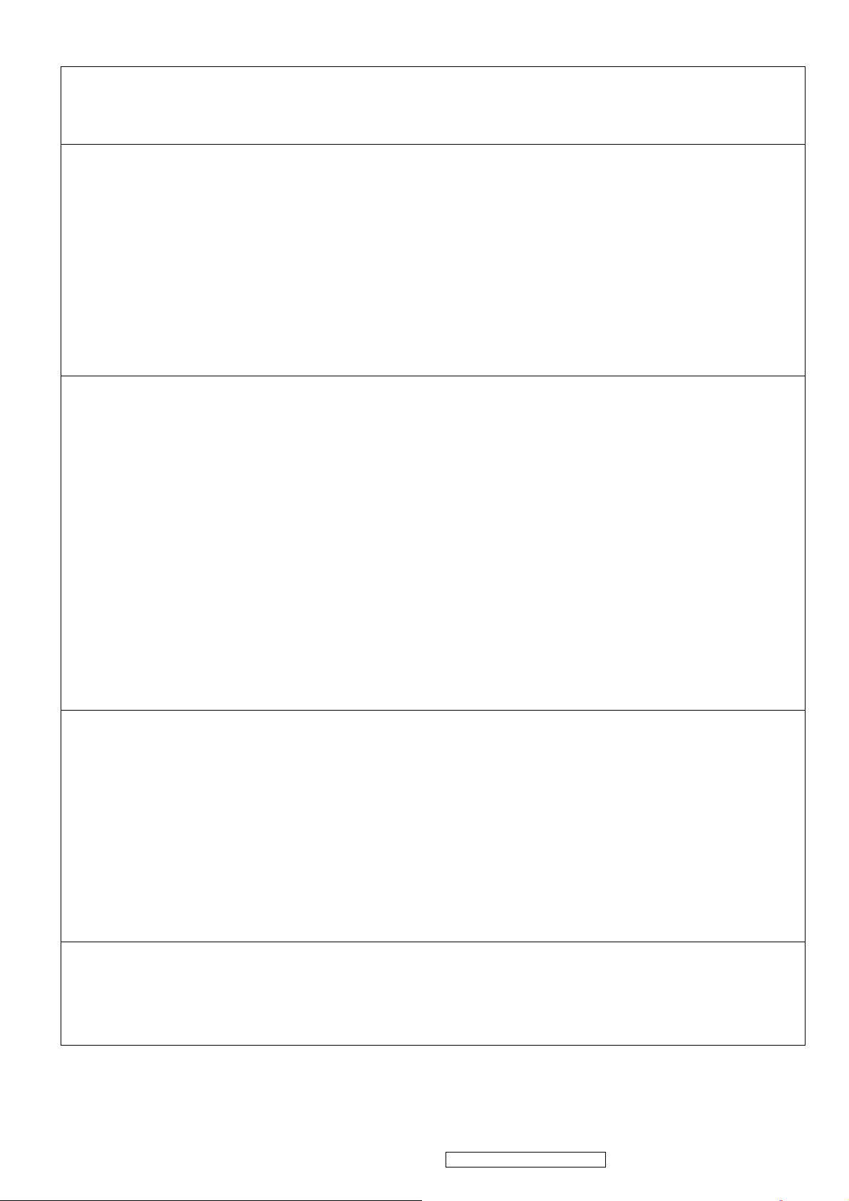
Main Menu :
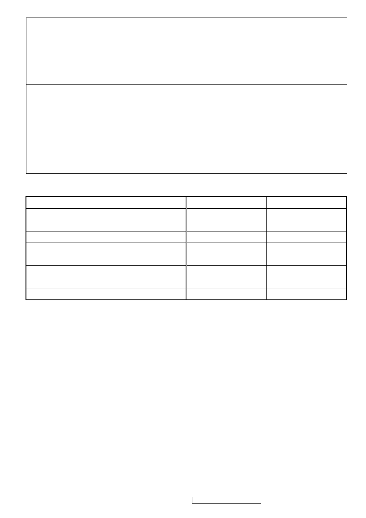
Auto Image Adjust :
To automatically adjust H./ V. Position, Phase adjust and Clock adjust.
REMARK: There may need to select “Manual Image Adjust” to optimized Performance for
various VGA tolerance.
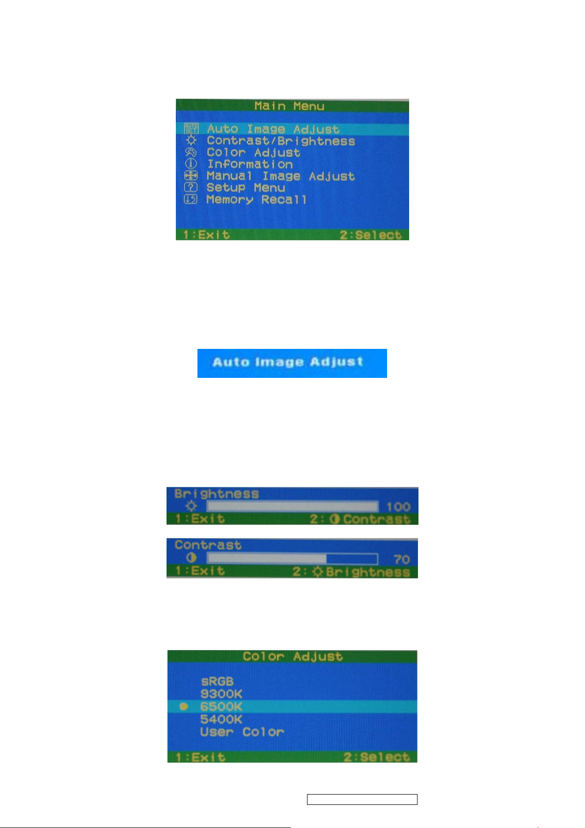
Contrast / Brightness :
To adjust the Contrast of the video and the backlight currency.
REMARK: 1. These functions setting can be recalled to default by [Up] + [Dn].
2. These functions should be disabled and setting to default in sRGB Mode.
Color Adjust :
To select the color temperature sRGB, 9300°K, 7500°K ,6500°K, 5400°K or user color.
15
ViewSonic Corporation Confidential - Do Not Copy VA1703w-1_VA1703wb-1
Page 19
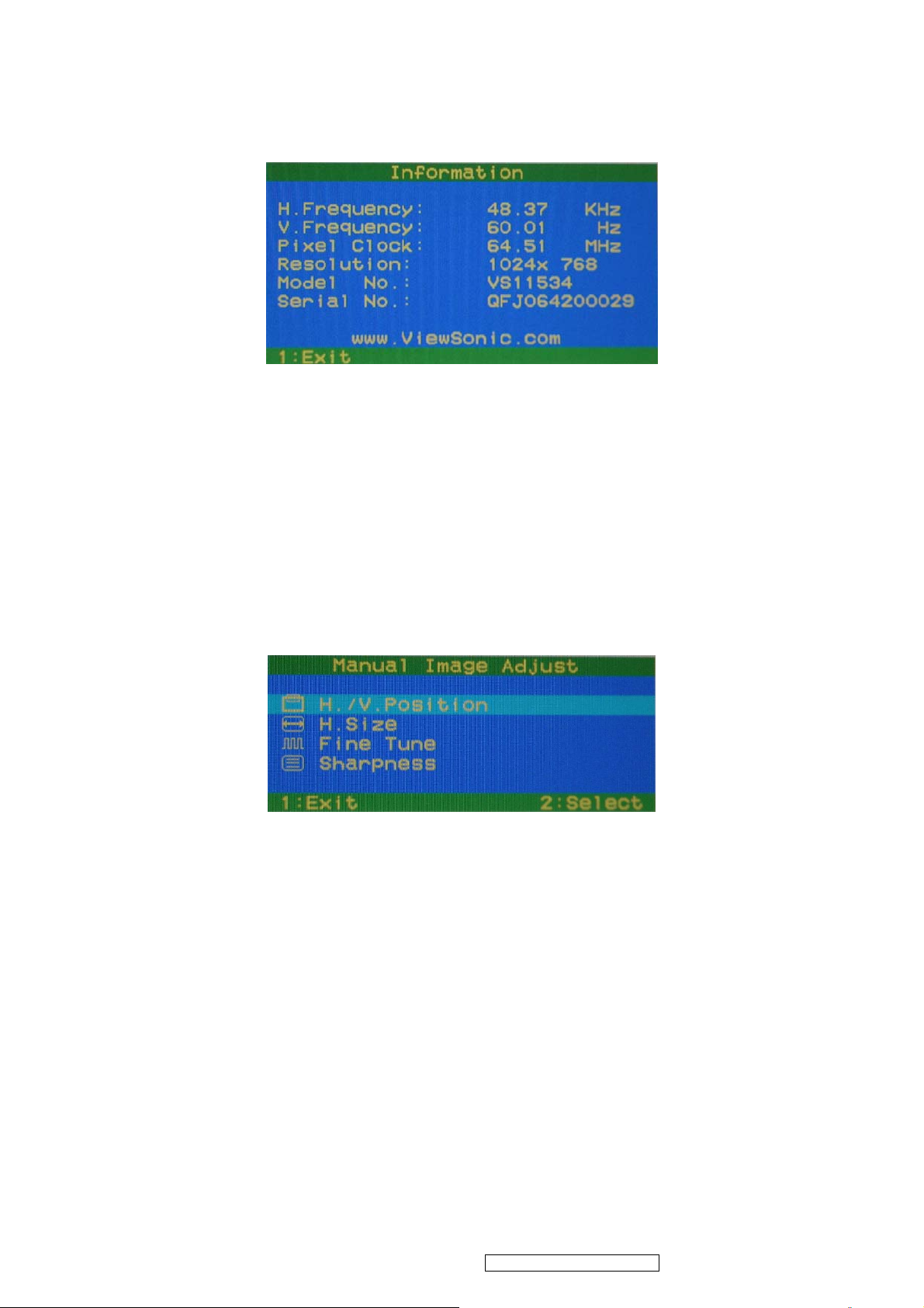
Information:
To display the data about Horizontal / Vertical frequency, Pixel clock, Resolution ,
Model number and Serial No. of the monitor.
Manual Image Adjust:
H./V. Position: To adjust the horizontal and vertical position of the video.
H./V. Size: To adjust the horizontal and vertical pixel clock of the video.
Fine Tune: To adjust the delay time of data and clock.
Sharpness: To select the picture sharpness of display.
REMARK: This function is available under Native Resolution Mode.
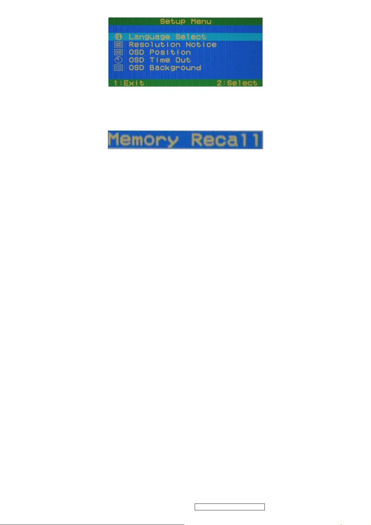
Setup Menu:
Language Select: To select one of ten languages.(English, French, German, Spanish,
Italian, Finnish, Japanese, Traditional Chinese, Simplified Chinese, and
Russian)
Resolution Notice: Enable (on) : OSD will notify the best picture quality resolution change
the resolution to 1440 x 900.
OSD Position: To set OSD position.
OSD Time out: To set the displaying time of OSD ( 5” / 15” / 30” / 60” ).
OSD Background: To select video background brightness.
16
ViewSonic Corporation Confidential - Do Not Copy VA1703w-1_VA1703wb-1
Page 20
Memory Recall:
Restore default settings of Clock, H./V. Position, Fine Tune, Contrast, Brightness, Color
temperature, OSD position, OSD timeout and Sharpness .
17
ViewSonic Corporation Confidential - Do Not Copy VA1703w-1_VA1703wb-1
Page 21

4. Circuit Description
4-1. Power supply (DC/DC Converter)
This brick convert is the 110-220AC input voltage to 12V AND 5V output for inverter,
audio, panel and system controller use.
It consists of a PWM IC (TEA1530AT, U105)
4-2. Scaling controller
The ADC is to convert RGB analog signal to digital signal that scaling chip can
acknowledge.
The HSYNC input receives a logic signal and provides the frequency reference for
pixel clock generation.
The scaling IC is to converts the input signal ranging from VGA to WXGA.
4-3. General description
The TSUM57AK is a high performance, and fully integrated graphics processing IC
solution for LCD monitors with resolutions up to WXGA. It is configured with an integrated
triple-ADC/PLL, a high quality scaling engine, an on-screen display controller, a built-in
output clock generator, and LVDS display interface. To further reduce system costs, the
TSUM57AK also integrates intelligent power management .
18
ViewSonic Corporation Confidential - Do Not Copy VA1703w-1_VA1703wb-1
Page 22

5. Adjustment Procedure
5-1. Function Test
● Product
- 17” LCD Monitor
● Test Equipment
- Color Video Signal & Pattern (or PC with WXGA resolution and a sound card)
● Test Condition
Before function test and alignment, each LCD Monitor should be run-in and warmed up for at least 30
minutes with the following conditions:
(a) In room temperature,
(b) With full-white screen, RGB, and Black
(c) With cycled display modes,
640*480 (H=37.5kHz, V=75Hz)
800*600 (H=46.9kHz, V=75Hz)
1024*768 (H=60kHz, V=75Hz)
1280*768 (H=60.3kHz, V=75Hz)
1280*1024 (H=80kHz, V=75Hz)
1440*900 (H=70.6kHz, V=75Hz)
● Test Display Modes & Pattern
Analog
1. 640 x 480 @ 60Hz, 31.5kHz
2. 640 x 480 @ 62Hz, 37.9kHz
3. 640 x 480 @ 75Hz, 37.5kHz
4. 800 x 600 @ 60Hz, 37.9kHz
5. 800 x 600 @ 72Hz, 48.1kHz
6. 800 x 600 @ 75Hz, 46.9kHz
7. 832 x 624 @ 75Hz, 49.7kHz
8. 1024 x 768 @ 60Hz, 48.4kHz
9. 1024 x 768 @ 70Hz, 56.5kHz
10. 1024 x 768 @ 75Hz, 60.0kHz
11. 1152 x 864 @ 75Hz, 67.5kHz
12. 1152 x 870 @ 75Hz, 68.7kHz
13. 1152 x 900 @ 67Hz, 62.5kHz
14. 1280 x 768 @ 60Hz, 47.8kHz
15. 1280 x 768 @ 75Hz, 60.3kHz
16. 1280 x 960 @ 60Hz, 59.7kHz
17. 1280 x 1024 @ 60Hz, 64.0kHz
18. 1280 x 1024 @ 75Hz, 80.0kHz
19. 1440 x 900 @ 60Hz, 55.9kHz
20. 1440 x 900 @ 75Hz, 70.6kHz
19
ViewSonic Corporation Confidential - Do Not Copy VA1703w-1_VA1703wb-1
Page 23

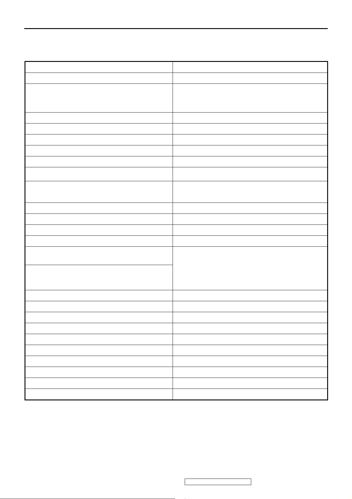
● Function Test Display Pattern
Item Test Content Pattern Specification Remark
1 Frequency & Tracking Fine Line Moire Eliminate visual wavy
noise.
2 Contrast/Brightness 16 Gray Scale 16 gray levels should be
distinguishable.
3 Boundary Horizontal &
Vertical Thickness
4 RGB Color
Performance
5 Screen Uniformity &
Flicker
6 Dead Pixel/Line White Screen &
7 White Balance White & Black
RGB Color
Intensities
Full White Should be compliant with the spec. Figure 7
Dark Screen
Pattern
Horizontal and Vertical position of video
should be adjustable to be within the
screen frame.
Contrast of each R, G, B, color should
be normal.
The numbers of dead pixels should be
compliant with the spec.
The screen must have the pure white
and black pattern, no other color.
Figure 1
Figure 2
Figure 3
Figure 4, 5,
6
Figure 7, 8
Figure 9
Fine Line Morie Pattern (Figure1) Gray Scale Pattern (Figure2)
Horizontal & Vertical Thickness Pattern (Figure 3) R. Color Pattern (Figure 4)
20
ViewSonic Corporation Confidential - Do Not Copy VA1703w-1_VA1703wb-1
Page 24

G. Color Pattern (Figure5) B. Color Pattern (Figure 6)
Full White Patter (Figure 7) Dark Screen Pattern (Figure 8)
Black-White Pattern (Figure 9)
21
ViewSonic Corporation Confidential - Do Not Copy VA1703w-1_VA1703wb-1
Page 25

5-2. Function Test and Alignment Procedure
● Memory Recall
You should do “Memory Recall” first. This action will allow you to erase all end-user’s settings and
restore the factory defaults.
● Auto Image Adjust
Please select and enter “Auto Image Adjust” function on Main Menu to see if it is workable.
The “Auto Image Adjust” function is aimed to offer a better screen quality by built-in ASIC. For
optimum screen quality, the user has to adjust each function manually.
● Firmware
Test Pattern: Burn In Mode ( Refer to Chapter 3-2. Short Cuts Function from the button(s) )
- Make sure the F/W is the latest version.
● DDC
Test Pattern: EDID program
- Make sure it can pass test program.
● Fine Tune and Sharpness
Test Signal: 1440x900 @ 60Hz
Test Pattern: Line Moire Pattern
- Check and see if the image has noise and focus performs well. Eliminate visual line bar.
- If not, readjust by the following steps:
(a) Select and enter “Fine Tune” function on “Manual Image Adjust” to adjust the image
to eliminate visual wavy noise.
(b) Then, select and enter “Sharpness” function to adjust the clarity and focus of the screen image.
● Boundary
Test Signal: 1440x900 @ 60Hz
Test Pattern: Horizontal & Vertical Line Thickness Pattern
- Check and see if the image boundary is within the screen frame.
- If not, readjust by the following steps:
(a) Select and enter “Manual Image Adjust” function on OSD Main Menu.
(b) Then, select and enter “Horizontal Size” or “Horizontal/Vertical Position” function to adjust the video
boundary to be full scanned and within screen frame.
● White Balance
Test Signal: 1440x900 @ 60Hz
Test Pattern: White and Black Pattern
● R, G, B, Colors Contrast
22
ViewSonic Corporation Confidential - Do Not Copy VA1703w-1_VA1703wb-1
Page 26

Test Signal: 1440x900 @ 60Hz
Test Pattern: R, G, B, Color Intensities Pattern and 16 Gray Scale Pattern
- Check and see if each color is normal and distinguishable.
- If not, please return the unit to repair area.
● Screen Uniformity and Flicker
Test Signal: 1440x900 @ 60Hz
Test Pattern: Full White Pattern
- Check and see if it is in normal condition.
● Dead Pixel and Line
Test Signal: 1440x900 @ 60Hz
Test Pattern: Dark and White Screen Pattern
- Check and see if there are dead pixels on LCD panel with shadow gauge and filter film.
- The total numbers and distance of dead pixels should be compliant with the spec.
● Mura
Test Pattern: White, RGB, Black, & Grey
Test Tool: 8% ND Filter
- Check if the Mura can pass 8% ND Filter.
● Check for Secondary Display Modes
Test Signal : Analog
640x350@70Hz 640x480@60HZ / 75HZ 720x400@70Hz
800x600@60HZ / 75HZ 832x624@75Hz 1024x768@60HZ / 75HZ
1280x768@60HZ / 75HZ 1280x1024@60HZ / 75Hz 1440x900 @ 75Hz
- Normally when the primary mode 1440x900 @ 60Hz is well adjusted and compliant with the specification,
the secondary display modes will be great possible to be compliant with the spec. But we still have to
check with the general test pattern to make sure every secondary is compliant with the specification.
● Memory Recall
After final QC step, we have to erase all saved changes again and restore the factory defaults. You
should do “Memory Recall” again.
● Power Off Monitor
Turn off the monitor by pressing “Power” button.
23
ViewSonic Corporation Confidential - Do Not Copy VA1703w-1_VA1703wb-1
Page 27

5-3. Firmware Upgrade Procedure
When you receive the returned monitor, please check whether the firmware version is the latest. If not, please
do the following procedures to upgrade it to the latest version.
5-3-1. Equipment Needed
- VA1703w / wb-1 Monitor
- Fixture for Firmware Upgrade
- VGA Cable
- PC (Personal Computer)
- ISP Tool
- Firmware Upgrade Program
- One additional monitor for checking the program execution
5-3-2. ISP tool instruction
15 pin D-Sub LPT cable
ISP tool Use 12V adapter
ISP connect method
24
ViewSonic Corporation Confidential - Do Not Copy VA1703w-1_VA1703wb-1
Page 28

5-3-3. ISP Download program procedure
● Hardware Connect status:
● Firmware Version update
1. Check : Monitor model
2. Check : Firmware version
Firmware
Version
Factory Mode :
a. Hold on [2] + [
b. Press [
3. Update final firmware version ( Refer to Chapter 5-3-4. )
Example :
1. Check : Monitor model : VA1703w / wb-1
2. Check : Firmware version : VA1703wb_ AL_HSD170MGW1A00R30.3
3. Update final firmware version : VA1703wb_ AL_HSD170MGW1A00R30.4
25
] key exit factory mode.
] with signal (hold for 3 seconds) into the factory mode.
ViewSonic Corporation Confidential - Do Not Copy VA1703w-1_VA1703wb-1
Page 29

Panel type : 170MGW1A00
Firmware version : R30.4
● Change Main Board (Version update)
1. Check : Monitor model
2. Check : Firmware version
Firmware
Version
Factory Mode :
a. Hold on [2] + [
b. Press [
3. Change scaler board.
4. Update final firmware version. ( Refer to Chapter 5-3-4. )
5. Update EDID code. ( Refer to Chapter 5-3-5. )
] key exit factory mode.
] with signal (hold for 3 seconds) into the factory mode.
26
ViewSonic Corporation Confidential - Do Not Copy VA1703w-1_VA1703wb-1
Page 30

5-3-4. Mstar scaler ISP function
1. Enforce Mstar ISP_Tool program.
2. After Enforcing Mstar ISP_Tool Program, open Utility Window.
3. Enforce Mstar ISP Utility Window's Connect function, and Device Type's Dialog window will be
opened ,then press "Sure " on Dialog window.
4. Enforce Mstar ISP Utility window’s Read function.
27
ViewSonic Corporation Confidential - Do Not Copy VA1703w-1_VA1703wb-1
Page 31

5. Choose the path and the file of Binary code. ( VA1703w / wb-1 follows the same procedure)
6. Choose the path and file of Binary code ,and Program Bin Ready Dialog window will be opened,
then press "Sure" on Dialog window.
7. Enforce Mstar ISP "Auto" function of Utility window.
28
ViewSonic Corporation Confidential - Do Not Copy VA1703w-1_VA1703wb-1
Page 32

8. Enforce Mstar ISP Utility window "Run" and write in the data .
9. After writing in the data , Enforce Dis Connect function of Mstar ISP Utility window and the burn
in procedure will be completed.
29
ViewSonic Corporation Confidential - Do Not Copy VA1703w-1_VA1703wb-1
Page 33

DDC Key In Procedure
Note:
1. Every time after replacing the main board, you have to do the DDC key in.
2. If you find the DDC does not conform to the monitor, you have to do the DDC key in.
Equipment Needed
- VA1703w / wb-1 Series Monitor
- DDC Card
- PC
- RS232 cable
- VGA Cable or DVI Cable
DDC Card (D8330)
RS-232 Cable VGA Cable
Step 1 : Select VA1703w/wb-1 in Working Model column to show EDID data on left.
Example : VX1935wm ( VA1703w/wb-1 follows the same procedure )
30
ViewSonic Corporation Confidential - Do Not Copy VA1703w-1_VA1703wb-1
Page 34

Step 2 : Modify the column of Week of Manufacture and Year of Manufacture and ID serial Number then press “2B”
button for changing serial number data.
Example : VX1935wm ( VA1703w/wb-1 follows the same procedure )
Step 3 : You will see the result as follows.
31
ViewSonic Corporation Confidential - Do Not Copy VA1703w-1_VA1703wb-1
Page 35

5- 4. Packing For Shipping And Disassembly Procedure
5-4-1. Packing For Shipping ( Packing Procedure )
● Put the monitor in the PE bag and seal the bag with tape. (Figure 1 ~ 2)
(Figure 1) (Figure 2)
● Put the cushions on the monitor. ● Put all accessories in the PE bag.
(Figure 3) (Figure 4)
D-Sub Cable Power cord
(Figure 3) (Figure 4)
● Place the monitor into the carton and then put all the accessories into the carton. At last, close the carton
and seal it with tape. (Figure 5 ~ 6)
User’s manual / Warranty card/
Base short side turn upward
CD package
Panel side forward
(Figure 5) (Figure 6)
32
D-Sub Cable
Power Cord
ViewSonic Corporation Confidential - Do Not Copy VA1703w-1_VA1703wb-1
Page 36

5-4-2. Disassembly Procedure
1.Remove the base. 2.Remove the hinge cover.
3.Hinge Cover. 4.Unfasten 4 pcs of screws to remove base.
5. Base Set. 6.Unfasten 7 pcs of screws with back cover.
33
ViewSonic Corporation Confidential - Do Not Copy VA1703w-1_VA1703wb-1
Page 37

7.Separate the Cover from the bottom of the Housing by using a Flat tool to remove back cover.
10.Tear off the tape and disconnect the cable of Main
board.
11.Unfasten 6 pcs of screws with Shielding and remove
Hinge Bracket.
34
ViewSonic Corporation Confidential - Do Not Copy VA1703w-1_VA1703wb-1
Page 38

12.Hinge Bracket . 13. Disconnect the cable of Panel.
14.Unfasten 4 pcs of screws with Shielding. 15.Unfasten 9 pcs of screws to remove P/I board and
Main board.
16.P/I Board ; Main Board ; Panel cable. 17.Set the short pin before changing new P/I board.
35
ViewSonic Corporation Confidential - Do Not Copy VA1703w-1_VA1703wb-1
Page 39

18.Tear off the AL foil tape and unfasten 2 pcs of screws
to remove Key board .
20.Pull and open the fixed support to remove Front
Bezel.
19.Key Board ; Key cable.
21.Bezel .
22.Unfasten 2 pcs of screws to remove Panel
bracket_L .
36
23.Unfasten 2 pcs of screws to remove Panel
bracket_R .
ViewSonic Corporation Confidential - Do Not Copy VA1703w-1_VA1703wb-1
Page 40

6. Troubleshooting Flow Chart
Q1
NO POWER
Please check if power cable is
connected properly
YES
NO
Q2
NO DISPLAY
Please check if signal cable is
connected properly
YES
NO
Change P/I board (ps)
Please reconnect power cable
Change Panel
Please reconnect signal
cable
Q3
Display Panel have horizontal
line or vertical line or
Q4
The backlight is OFF
1
Please check inverter wire if
properly connected
Please change Panel or P/I
2
board (ps)
Please
37
ViewSonic Corporation Confidential - Do Not Copy VA1703w-1_VA1703wb-1
Page 41

Q5
Display panel have block bar
Q6
Display panel with missing
color
Please change Panel
1
Please check signal cable if
connected properly and
check all pins are good
without bent
(ps) : P/I board Power/Inverter board
2
Please check if panel wire is
loose connection or not
3
Please
38
ViewSonic Corporation Confidential - Do Not Copy VA1703w-1_VA1703wb-1
Page 42

7. Block Diagram
39
ViewSonic Corporation Confidential - Do Not Copy VA1703w-1_VA1703wb-1
Page 43

8. Schematic Diagrams
PC5V
VCC3.3
PC5V
VCC3.3
M03 TSUM56/57AK SCHEMATIC
XGA/SXGA RSDS/LVDS OUTPUT
RIN
GNDR
GIN
GNDG
SOG
BIN
GNDB
HSYNC
VSYNC
DET_VGA
DDCA_SDA
DDCA_SCL
RIN
GNDR
GIN
GNDG
SOG
BIN
GNDB
HSYNC
VSYNC
DET_VGA
DDCA_SDA
DDCA_SCL
VCC1.8
VCC3.3
VCC1.8
+5V
VCC3.3
+5V
DVI5V
VCC1.8
VLCD
VCC3.3
+12V
+5V
+5V
DVI5V
PC5V
R+
R-
+5V
DVI5V
DDCD_SDA
G+
G-
B+
B-
CLK+
CLK-
DET_DVI
DDCD_SCL
4.INPUT
PC5V
Adj_BACKLIGHT
+5V
+12V
VCC3.3
VCC1.8
VLCD
DVI5V
VCTRL
on_Panel
on_BACKLIGHT
3. DC to DC POWER
R+
RG+
GB+
BCLK+
CLKDET_DVI
DDCD_SDA
DDCD_SCL
VCTRL
on_PANEL
adj_BACKLIGHT
on_BACKLIGHT
SPR
SPL
Volume
AUDIO_MUTE
AUDIO_STBY
PA[0..7]
PA[8..13]
PA[14..19]
PB[0..5]
PB[6..11]
PB[12..23]
GPO[0..4]
ESP
OSP
PA[0..7]
PA[8..13]
PA[14..19]
PB[0..5]
PB[6..11]
PB[12..23]
GPO[0..4]
SPR
SPL
Volome
AUDIO_MUTE
AUDIO_STBY
2. AUDIO
PA[0..7]
PA[8..13]
PA[14..19]
PB[0..5]
PB[6..11]
PB[12..23]
GPO[0..4]
ESP
OSP
+12V+5V
+5V
+12V
VLCD
40
ViewSonic Corporation Confidential - Do Not Copy VA1703w-1_VA1703wb-1
5.SCALER
VLCD
6.PANEL INTERFACE
ViewSonic Corporation
Model
Title
Block diagram
Date Rev:
Page 44

CN2
12V
GND GND
Power
12V
12
34
56
78
600 OHM
FB5
+12V
C13
0.1u
600 OHM
FB6
+5V
BL_ON5V5V
BL_ADJ
C14
0.1u
R13
10K
+5V
C
E
Q2
MMBT3904
R14 NC/0
B
R16 4K7
+5V
+5V+5V
R15
10K
on_BACKLIGHT
5
on_Panel
R29
10K/NC
VCC3.3 +5V
+5V
C21
+
100uF/16V
R30
10K
R35 4K7
C28
C23
100nF
10K/NC
0.1uF
U3
AIC1084PM-3V3
VCC3.3 +5V
R25
B
1
R34 NC
C
Q7
E
MMBT3904
VOUTVIN
VSS
TAB
R26
10K
R27
10K
B
23
4
+5V
C
Q6
E
MMBT3904
C22
+
100uF/16V
R28
10K/NC
VCC3.3
VLCDVCC3.3
C17
1uF
C24
100nF
Q4
AO3401
+
C26
10uF/16V
R19 4K7
+5V
R31
0
R36
10K
R17
1K
R20 NC/0
Q3
C
E
MMBT3904
VCC3.3
R21 4K7
B
VCC3.3 VCC1.8
C19
0.1uF
R32
NC
NC/1uF/16V
C22 can delete
C27
R18
10K
SOT-223
U2
3 2
+
Adj_BACKLIGHT 5
AIC1117PY-1V8
VI VO
4
VO
GND
1
B
D4
NC/1N4148
R37
NC/100
C
Q5
E
NC/CHT2907
C18
100uF/16V
D3
NC/1N4148
+
C20
0.1uF
R24
NC/56
+
C25
NC/4.7uF/16V
R33
NC/2K
VCTRL 5
VCC3.3
H1
678
123
123
5
678
5
4
4
TP
9
9
H2
678
123
123
5
678
5
4
4
TP
9
9
H3
678
123
123
5
678
5
4
4
TP
9
9
+12V2
41
ViewSonic Corporation Confidential - Do Not Copy VA1703w-1_VA1703wb-1
+12V
+5V2,4,5
DVI5V4
PC5V4
VCC3.34,5
VLCD6
VCC1.85
+5V
DVI5V
PC5V
VCC3.3
VLCD
VCC1.8
Recommond to used "Blue" parts circuit
for VCC1.8V if you want to suppoert DDC
function when system power off
ViewSonic Corporation
Model
Title
POWER
Date Rev:
Page 45

11
12
13
14
15
CLK_DDC
DAT_DDC
CN3
DB15
17
16
FB7 30 OHM BEAD
1
6
2
7
3
8
4
9
5
VGA_CON
10
HSI
VSI
PC5V
D10
NC/MLL5232B 5.6V
D11
NC/MLL5232B 5.6V
FB8 30 OHM BEAD
3
D5
BAV99
C39 NC/0.1uF
1
2
FB9 30 OHM BEAD
3
D6
BAV99
C40 NC/0.1uF
1
2
R54 100
R107
R2.2k
R56 100
R108
R2.2k
75Ω 1/16W
3
D7
BAV99
C41 NC/0.1uF
2
C44
18pF
C49
180pF
1
R44
+5V
1 2
11 10
C33
NC
147
147
75Ω 1/16W
U5A
74LVC14
U5E
74LVC14
R42
3 4
75Ω 1/16W
R43
C34
NC
147
U5B
74LVC14
147
U5F
13 12
74LVC14
R38 56Ω 1/16W
R39 56Ω 1/16W
R40 56Ω 1/16W
R41 470Ω 1/16W
C35
NC
R45 100Ω 1/16W
R46 100Ω 1/16W
R47 100Ω 1/16W
+5V
R48
10KΩ 1/16W
D9
NC/MLL5232B 5.6V
R55 22
C45
68pF
R57 22
C50
68pF
R49 100Ω 1/16W
VCC3.3
+5V
C29 0.047uF
C30 0.047uF
C31 0.047uF
C32 1000pF
C36 0.047uF
C37 0.047uF
C38 0.047uF
B1 220z/100M
B2 NC
C46
10uF
RIN 5
GIN 5
BIN 5
SOG 5
GNDR 5
GNDG 5
GNDB 5
DET_VGA 5
R52 100Ω 1/16W
R53 100Ω 1/16W
HSYNC 5
VSYNC 5
C47
100nF
10KΩ 1/16W
147
5 6
74LVC14
U5C
R50
+5V
R51
10KΩ 1/16W
2
+5V
2
3
147
9 8
DVI5V
1
PC5V
1
BAT54C-GS08
8
7
6
U5D
74LVC14
D8
U4
VCC
WP
SCL
AT24C02N-10SC
A0
A1
A2
GNDSDA
C42
0.1uF
1
2
3
45
DDCA_SCL 5
DDCA_SDA 5
TXC+
TXC-
TX0-
TX0+
SH05
SHCK
DSCL
DSDA
TXCTXC+
DVI5V
HPD
2
NC/0.1uf
3
C53
TX2TX1TX2+
TX1+
TX0+
TX0-
D13
BAV99
1
2
NC/0.1uf
3
C54
D14
BAV99
1
2
NC/0.1uf
3
C55
D15
BAV99
CN4
DVI
17
18
19
20
21
22
23
24
TX2-
1
TX1-
9
TX2+
2
TX1+
10
SH24
3
SH13
11
4
12
5
13
DSCL
6
DVI5V
14
DSDA
7
GNDD
15
8
16
HPD
R58 100Ω 1/16W
R59 100Ω 1/16W
3
D16
BAV99
C56
2
1
NC/0.1uf
3
D17
BAV99
C57
1
2
NC/0.1uf
2
1
NC/0.1uf
42
ViewSonic Corporation Confidential - Do Not Copy VA1703w-1_VA1703wb-1
3
C58
D18
BAV99
1
2
NC/0.1uf
R60
0Ω 1/16W
C51
0.1uF
3
D19
BAV99
C59
1
R61 100Ω 1/16W
R64 10Ω 1/16W
R65 10Ω 1/16W
R66 10Ω 1/16W
R67 10Ω 1/16W
R68 10Ω 1/16W
R69 10Ω 1/16W
R70 10Ω 1/16W
R71 10Ω 1/16W
3
D20
BAV99
C60
1
2
NC/0.1uf
DET_DVI 5
10KΩ 1/16W
R- 5
G- 5
R+ 5
G+ 5
B+ 5
B- 5
CLK- 5
CLK+ 5
R62
+5V
R63
10KΩ 1/16W
Del
R72
10K
D21
3.6V
3
D12
BAT54C-GS08
U6
8
VCC
7
WP
6
SCL
AT24C02N-10SC
+5V
DVI5V
PC5V
VCC3.3
C52
0.1uF
1
A0
2
A1
3
A2
45
GNDSDA
+5V
DVI5V
PC5V
VCC3.3
2,3,5
3
3
3,5
ViewSonic Corporation
Model
Title
INPUT
Date Rev:
Page 46

NC/AAT3520-IGY
U9
C83
3
10uF/16V
2
1
R75
10K
4
4
4
4
4
4
4
4
4
4
4
4
4
4
4
4
4
4
4
4
+5V
4
VCC3.3
C82
0.1uF
Option for ESD
C84
C85 22pF
0.22uF
C93 22pF
VCC3.3
R80 NC
R83 NC
RIN
GNDR
GIN
GNDG
SOG
BIN
GNDB
HSYNC
VSYNC
DDCA_SDA
DDCA_SCL
R+
RG+
GB+
B-
CLK+
CLKDDCD_SDA
DDCD_SCL
AVDD
R74 390 1%
U8
8
VDD
7
HOLD#
3
WP#
4 5
VSS SDI
SST25VH010
X1
14.318MHZ-20p
R87
10K
C95
0.1uF
C81
SDO
CE#
SCK
0.1uF
R76
22
R77
22
95
VDDP
VDDP
103
VDDP
115
VDDP
VDDCVDDP
12
VDDC
97
VDDC
117
VDDC
R73
NC
C61
68
CLKBP/LVBCKP
CLKBN/LVBCKM
PWM2/GPIO_P24
GPIO_P27/PWM1
PWM1/GPIO_P25
GPIO_P17/SAR0
GPIO_P00/SAR1
GPIO_P01/SAR2
GPIO_P02/SAR3
PWM0/GPIO_P26
DDCROM_SDA
0.1uF
VCTRL
NC/LVACKP
NC/LVACKM
VDD_OTP
RA1P/LVA2P
RA1N/LVA2M
RA2P/LVA1P
RA2N/LVA1M
RA3P/LVA0P
RA3N/LVA0M
GA1P/NC
GA1N/NC
GA2P/NC
GA2N/NC
GA3P/LVA3P
GA3N/LVA3M
BA1P/NC
BA1N/NC
BA2P/NC
BA2N/NC
BA3P/NC
BA3N/NC
RB1P/NC
RB1N/NC
RB2P/NC
RB2N/NC
RB3P/NC
RB3N/NC
GB1P/NC
GB1N/NC
GB2P/NC
GB2N/NC
GB3P/NC
GB3N/NC
CLKAP/LVB3P
CLKAN/LVB3M
NC/LVB2P
NC/LVB2M
BB1P/LVB1P
BB1N/LVB1M
BB2P/LVB0P
BB2N/LVB0M
BB3P/NC
BB3N/NC
ESP
OSP
GPO0
GPO1
GPO2
GPO3
GPO4
GPO5
GPO6
GPIO_P22
GPIO_P23
GPIO_P03
GPIO_P16
GPIO_P15
GPIO_P12
GPIO_P06
GPIO_P07
GPIO_P13
GPIO_P14
DDCROM_SCL
11
107
108
109
110
111
112
113
114
98
99
100
101
105
106
89
90
91
92
93
94
9
10
15
16
17
18
2
3
5
6
7
8
118
119
120
121
122
123
124
125
126
127
128
1
80
81
88
87
86
85
84
83
82
75
74
26
35
69
78
79
20
21
22
23
24
25
27
28
29
30
31
77
76
PA0
PA1
PA2
PA3
PA4
PA5
PA6
PA7
PA8
PA9
PA10
PA11
PA12
PA13
PA14
PA15
PA16
PA17
PA18
PA19
PB0
PB1
PB2
PB3
PB4
PB5
PB6
PB7
PB8
PB9
PB10
PB11
PB12
PB13
PB14
PB15
PB16
PB17
PB18
PB19
PB20
PB21
PB22
PB23
ESP
OSP
GPO0
GPO1
GPO2
GPO3
GPO4
R78 100
R79 100
R90 100
R92 100
R93 100
R95 4K7
R96 4K7
R97
10K
VCC3.3
R98
10K
R99 100
R100 100
VCTRL
P[0..7]
PA[8..13]
PA[14..19]
PB[0..5]
PB[6..11]
PB[12..23]
GPO[0..4]
2..4
MINUS
PLUS
MENU
AUTO
POWER
C96
0.1uF
VCC1.8
3
VCC3.3
3,4
3
PA[0..7]
PA[8..13]
PA[14..19]
PB[0..5]
PB[6..11]
PB[12..23]
ESP 6
OSP
GPO[0..4]
DET_DVI
DET_VGA
on_PANEL 3
on_BACKLIGHT
adj_BACKLIGHT
Volume
AUDIO_MUTE
AUDIO_STBY
U10 24C16
8
VCC
7
WP
6
SCL
+5V
1
A0
2
A1
3
A2
45
GNDSDA
6
6
6
6
6
6
6
6
+5V
R84
10K
R89 20K
C94 0.1uF
2
2
2
VCC1.8
VCC3.3
+5V
4
4
3
3
VCC3.3
FB10
C73
10uF/16V
B
600 OHM
600 OHM
C88
0.1uF
+5V
R82
470
E
Q8
PMBS3906
C
FB12
+
C77
0.1uF
C89
0.1uF
R91 470
VCC1.8
600 OHM
VCC3.3 VDVI VCC3.3 VPLL VMPLLVCC3.3
FB13
600 OHM
C72
10uF/16V
VCC3.3
FB16
600 OHM
10uF/16V
+5V
R85
10K
B
PMBS3906
FB11
C62
4.7uF/16V
C79
R86
470
E
Q9
C
R94 470
VDDC
+
C75
0.1uF
AVDD
+
+
C80
0.1uF
C63
0.1uF
C76
0.1uF
C64
0.1uF
LED_G
C65
0.1uF
AUTO
MENU
POWER
PLUS
LED_A
LED_G
C86
0.1uF
FB14
600 OHM
C87
0.1uF
R81
10K
C66
10uF/16V
C90
0.1uF
LED_A
VDDP
C91
0.1uF
+
C67
0.1uF
FB15
600 OHM
10uF/16V
MINUS
C92
0.1uF
C74
C68
0.1uF
C70
C69
0.1uF
0.1uF
+
C78
0.1uF
SPL2
SPR2
ViewSonic Corporation
C71
0.1uF
SPL
SPR
CN5
1
2
3
4
5
6
7
8
9
10
11
12
KBD2
VPLLVDVI VMPLL
AVDD
44
RIN0P
RIN0N
GIN0P
GIN0N
SOGIN0
BIN0P
BIN0N
HSYNC0
VSYNC0
DDCA_SDA
DDCA_SCL
RX2P
RX2N
RX1P
RX1N
RX0P
RX0N
RXCKP
RXCKN
DDCD_SDA
DDCD_SCL
REXT
REFP
REFM
SDO
SCZ
SCK
SDI
50
AVDD_DVI
U7
59
58
56
55
57
54
53
63
64
65
66
39
40
42
43
45
46
48
49
36
37
51
62
61
70
2
71
1
72
6
73
34
AVDD_DVI
AVDD_MPLL
52
67
14
60
VDDP
AVDD_PLL
AVDD_ADC
TSUM57AK
19
RST
32
XIN
33
XOUT
102
MODE[0]
104
MODE[1]
R88
10K
4
BYPASS
GND
GND
GND
GND
41
47
3896116
GND
GND
13
Model
Title
SCALER
Date Rev:
43
ViewSonic Corporation Confidential - Do Not Copy VA1703w-1_VA1703wb-1
Page 47

PB[0..5]5
8
7
6
C99
NC
PA[0..7]
PB[12..23]
C100
NC
C101
NC
PA2 LVA2P
PA12 LVA3P
PA13 LVA3M
PB13
PB14
PB15 LVBCKM
PB16
PB17
PB18
PB20 LVB0P
PB21 LVB0M
C103
C102
NC
NC
LVACKPPA0
LVACKMPA1
LVA2MPA3
LVA1PPA4
LVA1MPA5
LVA0PPA6
LVA0MPA7
LVB3PPB12
LVB3M
LVBCKP
LVB2P
LVB2M
LVB1P
LVB1MPB19
GPOO0
GPOO1
GPOO2
GPOO3
GPOO4
PB[6..11]5
PB[12..23]5
OSP5
ESP5
PA[0..7]
PA[8..13]
PA[14..19]
GPO[0..4]
PA[8..13]
GPO[0..4]
PA[0..7]
RA1PPA2
PA3
RA1N
RA2PPA4
PA5
RA2N
PA6
RA3P
PA7
RA3N
PA8
GA1P
GA1NPA9
GA2PPA10
GA2NPA11
PA12 GA3P
GA3NPA13
BA1PPA14
BA1NPA15
BA2PPA16
BA2NPA17
BA3PPA18
BA3NPA19
PB12
CLKAP
PB13
CLKAN
GPO0
GPO1
GPO2
GPO3
GPO4
PA[0..7]5
PB[12..23]5
RP1 NC/0Rx4
1
2
3
4 5
R103 NC/0
PB[0..5]
PB[6..11]
PB[12..23]
OSP
ESP
PB0
RB1P
PB1
RB1N
PB2
RB2P
PB3
RB2N
PB4
RB3P
PB5
RB3N
PB6
GB1P
PB7
GB1N
PB8
GB2P
PB9
GB2N
PB10
GB3P
PB11
GB3N
CLKBP
PB14
PB15 CLKBN
PB18
PB19
PB20 BB2P
PB21 BB2N
PB22 BB3P
PB23 BB3N
R101 NC/0
R102 NC/0
J1
BB1P
BB1N
C97
NC
C98
NC
RA3N
RA3P
RA2N
RA2P
RA1N FB2N
RA1P
GA3P FG0P
GA2N
GA2P FG1P
GA1N
GA1P FG2P
CLKAN
CLKAP FCLKP
BA3N
BA3P
BA2N
BA2P
BA1N FR2N
BA1P FR2P
VLCD
FB0N
FB0P
FB1N
FB1P
FB2P
FG0NGA3N
FG1N
FG2N
FCLKN
FR0N
FR0P
FR1N
FR1P
STH
LPGPOO1
POLGPOO0
HMS
CLKVGPOO3
STVGPOO2
OEGPOO4
C104
NC
CN6
50
49
48
47
46
45
44
43
42
41
40
39
38
37
36
35
34
33
32
31
30
29
28
27
26
25
24
23
22
21
20
19
18
17
16
15
14
13
12
11
10
9
8
7
6
5
4
3
2
1
VLCD3
RB3N B0N
RB3P B0P
RB2N B1N
RB2P B1P
RB1N B2N
RB1P B2P
BG0NGB3N
BG0PGB3P
BG1NGB2N
BG1PGB2P
BG2NGB1N
BG2PGB1P
BCLKNCLKBN
BCLKPCLKBP
BB3N BR0N
BB3P BR0P
BB2NBB2N BR1N
BB2P BR1P
BR2NBB1N
BR2PBB1P
VLCD
CN7
30
29
28
27
26
25
24
23
22
21
20
19
18
17
16
15
14
13
12
11
10
9
8
7
6
5
4
3
2
1
IL-FHR-B30S-HF (JAE)
RXO0-LVB0M
LVB2M
LVBCKM
LVB3M
LVA1M
LVA2M
LVACKM RXECLVA3M
RXO1-LVB1M
RXO2RXOC-
RXO3RXE0-LVA0M
RXE1RXE2-
RXE3-
CN8
1 2
3 4
5 6
7 8
9 10
11 12
13 14
15 16
17 18
19 20
21 22
23 24
25 26
CON26A
RXO0+ LVB0P
RXO1+ LVB1P
RXO2+
RXOC+
RXO3+
RXE0+ LVA0P
RXE1+ LVA1P
RXE2+ LVA2P
RXEC+ LVACKP
RXE3+ LVA3P
VLCDVLCD
LVB2P
LVBCKP
LVB3P
VLCD
RXO0-LVB0M
RXO0+LVB0P
RXO1-LVB1M
LVB2M RXO2-
LVBCKM RXOC-
LVACKM RXEC-
RXO1+LVB1P
RXO2+LVB2P
RXOC+LVBCKP
RXO3-LVB3M
RXO3+LVB3P
RXE0-LVA0M
RXE0+LVA0P
RXE1-LVA1M
RXE1+LVA1P
RXE2-LVA2M
RXE2+LVA2P
RXEC+LVACKP
RXE3-LVA3M
RXE3+LVA3P
R104 0
R105 NC
R106 NC
1
1
2
2
3
3
4
4
5
5
6
6
7
7
8
8
9
9
10
10
11
11
12
12
13
13
14
14
15
15
16
16
17
17
18
18
19
19
20
20
21
21
22
22
23
23
24
24
25
25
26
26
27
27
28
28
29
29
30
30
CNT206-30XX
LVDS Panel
RSDS Panel
IL-FHR-B50S-HF (JAE)
CN1 CN2 CN3 RP1 R1 R2 R4 Table 1
XX XXXX X
V
VVVV V
XVV
ViewSonic Corporation
Model
Title
PANEL INTERFACE
Date Rev:
44
ViewSonic Corporation Confidential - Do Not Copy VA1703w-1_VA1703wb-1
Page 48

CN101
CN8-5
CN16-1
1
+12V_Inverter
2
+12V_Inverter
3
4
5
+5V
6
+5V
7
ADJ
8
ON/OFF
CN100
16
LED-G
15
LED-B
14
SW5-MENU
13
SW4-VOL+
12
SW3-POWER
11
SW2-VOL-
10
SW1-AUTO
9
VOLOME
8
AUDIO_STBY
7
AUDIO_MUTE
6
ADJ
5
ON/OFF
4
3
2
1
+5V
+12V_AUDIO
+
CE102
220u/25V
GND
+
R100
150/J
CE101
220u/25V
1SMA4738
ZD100
0.47u/16V
C101
1000u/10V
DAC-12M051 A-INV-R0C5X05.SCH
DAC-12M051 A-INV-R0C5X05.SCH
DAC-12M051 A-AUDIO-R0C5X05.SCH
DAC-12M051 A-AUDIO-R0C5X05.SCH
L101
3.3uH
CE104
FB100
CE103
1000u/25V
3.3uH
++5V
L102
+
2200u/10V
R116
R117
GND
++5V
10K/F
R114
+
5V
+
CE105
C109
4.12K/F
4.99K/F
R105
R106
2
2
D108
SBT100-16LS
R107
R108
2
2
D109
SBT150-10LS
R113
10K/F
0.01u/50V
R115
3.3K/J
TL431
C102
0.1u/25V
20/J
20/J
1000p/250V
3
1
20/J
20/J
3
1
++5V
U103
ZD101
C103
3
1
C104
1000p/250V
3
1
R101
100R/J
6.8B
R103
1M/F
10
9
8
7
6 5
GND
390R/J
R112
U102
LTV-817B
2 1
RK7002
Q100
T100
EQ30
4.7K/F
1
3
T100-5
4
10R/J
R133
4
3
Z-70
100K/2W
L105
4.7uH
R130
+
47u/50V
R125
CE107
L107
C112
2200p/1KV
D104
UF1007
F100
4148
D105
L106
Z-31
R129
100R/(1/2W)-FUSIBLE
D
Q102
D
S
S
STP6NK60ZFP
10K/F
R126
10K/F
G
R137
0.01u/1KV
C113
+
100u/400V
R132
D106 4148
G
3.9K/J
R136
0.24R/1W
1
V+
4A/600V
V-4AC
CE106
15R/J
R134
4.7K/F
C114
0.22u/16V
3
DB100
AC
2
CX101
0.22u/275V
R135
13K/F
LF100
1
4
21A-3007A
8
DRAIN
7
HVS
6
DRIVER
SENSE
U105
TEA1530AT
2
3
PROTECT
CTRL
4.7K/F
330K/F
CX100
0.22u/275V
2R55(2.5ohm 5A)
VCC
GND
1
2
3
200K
45
R149
330K/F
R145
330K/F
R146
CY101
R147
RT100
+VCC
C116
1u/16V
R151
R148
1K/J
C117
0.01u/50V
CY100
E-GND
C118
NA
3.15A/250V
1
330p/250V
VAR100
1
2
2
330p/250V
ZD103
18B
R102
300
F101
CN6
1
2
E-GND
TVR10681
3
T100-5
R141
13K/F
D107
4148
C119
0.33u/16V
C120
R104
2.4K
560p/50V/COG
CY102
GND
2200p/250V
ViewSonic Corporation
Model
Title
Date Rev:
45
ViewSonic Corporation Confidential - Do Not Copy VA1703w-1_VA1703wb-1
Page 49

+12V_AUDIO
C300
+
470u/16V
C301
104P/50V
CN301
CN12-1
1
SPL
2
GND
3
SW1-AUTO
4
SW2-VOL-
5
SW3-POWER
6
SW4-VOL+
7
SW5-MENU
8
LED-B
9
LED-G
10
GND
11
12
SPR
2SJ-05101NC3
CN300
AUDIO_STBY
AUDIO_MUTE
VOLOME
8
C309
C310
474K/16V
474K/16V
R310
10K/F
4
9
6
11
12
C304
104P/50V
INL
INR
VOLUME
STBY
MUTE
1
C305
L301
0R/J
L302
0R/J
R305
1K/F
R306
NC
C306
NC
C307
NC
++5V
R307
NC
C308
R308
10K/F
R309
10K/F
Q300
NC
1
A
2
B
3
C
4
D
5
E
R312
R311
0R/J
L300
NC
47P/50V/COG
NC
47P/50V/COG
16
IC-TDA7496
GND
GND2GND3GND13GND18GND
15
OUTL
OUTR
SVR
VAROUT_R
VAROUT_L
GND
20
19
U300
17
14
10
7
5
+
C311
470u/16V
R301NCR302
NC
C312
470u/16V
+
C313
+
470u/16V
FB300
0.2A/300R/100MHZ
FB301
0.2A/300R/100MHZ
C302
221PK/50V
SPL
SPR
C303
221PK/50V
46
ViewSonic Corporation Confidential - Do Not Copy VA1703w-1_VA1703wb-1
ViewSonic Corporation
Model
Title
Date Rev:
Page 50

R215
1.2K
R213
1.2K
CN200
D203
BAV99
CN201
BAV99
D206
1
2
OP1
R212
680
R214
649
1
2
R216
22K
OP2
R230
1.2K
ON/OFF
ADJ
F200
4A/125V
R217
NA
IC VCC
C202
R200
68K
R220
22.6K
0.01u/50V
R201
100K
R203
68K
R204
75K
C204
220u/25V
C200
0.01u/50V
Q200
4401
Q202
RN2402
R235
1.5K
ZD200
5.6B
C201
0.1u/25V
R236
100
Q207
4401
R206
10
NA
C205
R209
NA
R208
2K
Q203
2N7002
ZD201
NA
R207
10
Q204
4401
R210
10
Q208
4403
4
3
2
1
IC201
FW342
5
6
4.7u/25V
7
8
4.7u/25V
T200A
EEL19A
C210
C211
72
85
C208
4.7u/25V
CY200
3p/6KV
C209
4.7u/25V
C213
6800p/50V
C214
6800p/50V
C216
5p/3KV
C217
5p/3KV
D202
BAV99
D204
BAV99
C220
0.022u/50V
CN204
R218
1K
1
S1
2
S1
4
S2
3
S1
5
S3
6
S4
C221
27p/50V
R221
68K
R224
33K
R222
68K
S1
S1 S3
16
1
C224
R202
100K
15
2
4700p/50V
C222
NA
R240
43K
S4
14
3
13
U200
BIT3713
4
11
12
5
6
C225820p/50V
C2271u/16V
C226
0.47u/16V
10
7
C203
8 9
0.1u/25V
R219
NA
R232
470K
D210
4148
R225
200K
IC VCC
R205
100K
D211
4148
D212
4148
C228
2200p/50V
C229
2200p/50V
R226
15K
R227
15K
OP1
OP2
R238
102K
R239
66.5K
C232
NA
R223
3.3K
R237
174K
47
ViewSonic Corporation Confidential - Do Not Copy VA1703w-1_VA1703wb-1
ViewSonic Corporation
Model
Title
Date Rev:
Page 51

9. PCB Layout Diagrams
48
ViewSonic Corporation Confidential - Do Not Copy VA1703w-1_VA1703wb-1
ViewSonic Corporation
Model
Title
Date Rev:
Page 52

49
ViewSonic Corporation Confidential - Do Not Copy VA1703w-1_VA1703wb-1
ViewSonic Corporation
Model
Title
Date Rev:
Page 53

50
ViewSonic Corporation Confidential - Do Not Copy VA1703w-1_VA1703wb-1
ViewSonic Corporation
Model
Title
Date Rev:
Page 54

51
ViewSonic Corporation Confidential - Do Not Copy VA1703w-1_VA1703wb-1
Page 55

10. Exploded Diagram and Exploded Parts List
52
ViewSonic Corporation Confidential - Do Not Copy VA1703w-1_VA1703wb-1
Page 56

y
g
g
g
N
m
N
N
N
N
N
g
N
p
N
N
p
N
N
N
N
(
p)
N
(
p)
y
y
Q
(
)
N
p
)
(
)
y
g
N
m
N
N
N
N
N
g
N
p
N
N
p
N
N
N
N
(
p)
N
(
p)
y
y
Q
(
)
N
p
)
(
)
EXPLODED PARTS LIST (VA1703W-1)
ViewSonic Model Number: VS11534
Rev: 1a
Serial No. Prefix: QFJ
Item ViewSonic P/N Ref. P/N Description Q't
1 C-00008244
2 PL-00008073
3 C-00008245
4
5
6
7
8
9
10 PL-00008001
11
12
13
14
15
16
17
18
19 C-00008242
20 C-00008243
21 E-00008169
22 B-00008233
23
24 B-00008234
/A
/A
/A
/A
/A
/A
/A
/A
/A
/A
/A
/A
/A
/A
/A
40-05010031G100 VA1703w Arm ABS-HB Black 2nd 1
40-06010030G100 VA1703w Base ABS-HB Black 2nd 1
40-07010009G100 VA1703w Hin
41-03010040G000 VA903 Base Bracket SECC T=1.6m
41-03010063G000 HW173 PANEL BRACKET L 1
41-03010064G000 HW173 PANEL BRACKET R 1
41-03010065G001 VA1703 HINGE BRACKET SECC 1
41-04010029G000 HW173A SHIELDING 1
41-07010025G000 VA903 Hin
42-02110002G000 HU171 Rubber Foot Black 6
43-01031004G010 SCREW T3x10 PAN BZ Ta
43-01040604G001 Screw M4×6 PAN BZ, Me, 6
43-04030602G010 Screw M3*6 Flat Ni Ta
43-12030502G000 SCREW M3*5 ROUND WASHER NI ME 21
43-12030805G010 SCREW M3*8 ROUND WASHER CZ TAP 2
43-12031002G000 SCREW M3x10 ROUND WASHER Ni Me 4
43-90000052G110 PHW+LWM4-18x10 TP-B Ni
43-90000052G110 PHW+LWM4-18x10 TP-B Ni
45-01A17001G100 VA1703w Bezel Sub-Ass
45-02A17001G100 VA1703w Backcover Sub-Ass
170MGW1-A00 LI
70-V1703000G001 VA1703 KEY BOARD ASS’Y
52-5W273001G000 POWER/INVERTER 2Lam
70-V7030102G500 VA1703 MB AL-NA ASS'Y
UID CRYSTAL DEVICE HSD170MGW1- 1
e Cover ABS-HB Black 2nd 1
e SECC=2mm 1
washer Ta
washer Ta
Silver 2nd 1
Black 2nd 1
w/o speakers
8.0mA/32W(FSP
Sirtec
1
1
6
3
3
1
1
1
EXPLODED PARTS LIST (VA1703WB-1)
ViewSonic Model Number: VS11534
Rev: 1a
Serial No. Prefix: QFK
Item ViewSonic P/N Ref. P/N Description Q't
1 C-00008249
2 PL-00008074
3 C-00008248
4
5
6
7
8
9
10 PL-00008001
11
12
13
14
15
16
17
18
19 C-00008246
20 C-00008247
21 E-00008169
22 B-00008233
23
24 B-00008234
/A
/A
/A
/A
/A
/A
/A
/A
/A
/A
/A
/A
/A
/A
/A
40-05010031G110 VA1703wb Arm ABS-HB Midni
40-06010030G110 VA1703wb Base ABS-HB Midni
40-07010009G110 VA1703wb H/C ABS-HB Midni
41-03010040G000 VA903 Base Bracket SECC T=1.6m
41-03010063G000 HW173 PANEL BRACKET L 1
41-03010064G000 HW173 PANEL BRACKET R 1
41-03010065G001 VA1703 HINGE BRACKET SECC 1
41-04010029G000 HW173A SHIELDING 1
41-07010025G000 VA903 Hin
42-02110002G000 HU171 Rubber Foot Black 6
43-01031004G010 SCREW T3x10 PAN BZ Ta
43-01040604G001 Screw M4×6 PAN BZ, Me, 6
43-04030602G010 Screw M3*6 Flat Ni Ta
43-12030502G000 SCREW M3*5 ROUND WASHER NI ME 21
43-12030805G010 SCREW M3*8 ROUND WASHER CZ TAP 2
43-12031002G000 SCREW M3x10 ROUND WASHER Ni Me 4
43-90000052G110 PHW+LWM4-18x10 TP-B Ni
43-90000052G110 PHW+LWM4-18x10 TP-B Ni
45-01A17002G100 VA1703wb Bezel Sub-Ass
45-02A17002G100 VA1703wb B/C Sub-Ass
170MGW1-A00 LI
70-V1703000G001 VA1703 KEY BOARD ASS’Y
52-5W273001G000 POWER/INVERTER 2Lam
70-V7030102G500 VA1703 MB AL-NA ASS'Y
UID CRYSTAL DEVICE HSD170MGW1-A 1
e SECC=2mm 1
Midnight-Gray 2nd 1
ht Gray 2nd 1
ht Gray 2nd 1
ht Gray 2nd 1
washer Ta
washer Ta
Mid-Gray 2nd 1
w/o speakers
8.0mA/32W(FSP
Sirtec
1
1
6
3
3
1
1
1
53
ViewSonic Corporation Confidential - Do Not Copy VA1703w-1_VA1703wb-1
Page 57

4
5
1
2
3
7
6
8
10
9
11
54
ViewSonic Corporation Confidential - Do Not Copy VA1703w-1_VA1703wb-1
Page 58

y
g
)
g
g
y
(M)
p
p
y
r
N
y
g
)
g
g
y
(M)
p
p
y
r
N
PACKING PART LIST ( VA1703W-1 )
ViewSonic Model Number: VS11534
Rev: 1a
Item ViewSonic P/N Ref. P/N Location Q't
DC-00008197
1
DC-00008196
DC-00008198
2 CB-00008097
3 A-00008004
4 P-00008242
5 P-00008004
6 P-00008240
7 P-00008241
8 PL-00008072
9 P-00008239
10 DC-00008004
11
/A
72-01170303G000 VA1703 Taiwan Packin
72-01170302G001 VA1703 China Packin
72-01170301G000 VA1703 USA Packin
33-R3910501G000 CABLE SIGNAL D/15P-15P
33-E3980011G000 PWR CORD TWN 125V/7A 1.8M 3C BLK "Linetek"
61-03000008G000 PE BAG 450*650mm
61-03000003G000 U171 PE BAG 225*400MM
61-01000051G000 VA1703 End Ca
61-01000052G000 VA1703 End Ca
42-01260013G000 M
60-01000097G001 VA1703w Carton, made in Taiwan
62-07000013G000 8ms sticke
62-06000003G000 BARCODE LABEL 76.2*76.2MM
lar 385*250*0.1(Protection) for 17"W
assy(TWN&EUR
Assy, made in China
Ass
1800MM-JHEN VEI
-L EPS
-R EPS
PACKING PART LIST ( VA1703WB-1 )
ViewSonic Model Number: VS11534
Rev: 1a
Item ViewSonic P/N Ref. P/N Location Q't
DC-00008197
1
DC-00008196
DC-00008198
2 CB-00008097
3 A-00008004
4 P-00008242
5 P-00008004
6 P-00008240
7 P-00008241
8 PL-00008072
9 P-00008244
10 DC-00008004
11
/A
72-01170303G000 VA1703 Taiwan Packin
72-01170302G001 VA1703 China Packin
72-01170301G000 VA1703 USA Packin
33-R3910501G000 CABLE SIGNAL D/15P-15P
33-E3980011G000 PWR CORD TWN 125V/7A 1.8M 3C BLK
61-03000008G000 PE BAG 450*650mm
61-03000003G000 U171 PE BAG 225*400MM
61-01000051G000 VA1703 End Ca
61-01000052G000 VA1703 End Ca
42-01260013G000 M
60-01000098G001 VA1703w Carton, made in Taiwan
62-07000013G000 8ms sticke
62-06000003G000 BARCODE LABEL 76.2*76.2MM
lar 385*250*0.1(Protection) for 17"W
-L EPS
-R EPS
assy(TWN&EUR
Assy, made in China
Ass
1800MM-
1
1
1
1
1
1
1
1
1
1
1
1
1
1
1
1
1
1
1
1
1
1
55
ViewSonic Corporation Confidential - Do Not Copy VA1703w-1_VA1703wb-1
Page 59

11. Recommended Spare Parts List
#
p
ViewSonic Model Number: VS11534
Serial No. Prefix: QFJ Rev: 1a
Item ECR/ECN ViewSonic P/N Ref. P/N Location Universal number
1 Power Cord 125V/7A 1.8M 3C Taiwan A-00008004
Accessories:
2 Power Cord - 250V/10A 1.8M 3C BLK (China) A-00008038
3 Power Cord - 125V/10A 1.8M 3C BLK (USA) A-00008039 33-E3980000G000
4 Power Cord - 250V/10A 1.8M 3C BLK (Europe) A-00008040
5
PC Board
Assembly:
6
7
8
Cabinets:
9
10
11
12
Cables:
Documentation:
13 Energy Star Label DC-00008001
14 Label - (QC-Pass China) DC-00008002
15 Hi-Pot Pass Label DC-00008003
16 8ms Sticker DC-00008004
17
18
19
Electronic
20
Com
onents:
Miscellaneous:
21
Packing Material:
22 PE BAG 225*400MM P-00008004
23
24
25
26
27
Plastics:
28
29
30
Key Board (w/o speakers)
Main Board - AL-NA (Sirtec)
Power/Inverter Board - (2Lamp 8.0mA/32W)
Front Panel (Silver)
Back Cover (Black)
Cover - (Arm ABS-HB Black)
Cover - Hinge Cover
Video Cable - (Signal Cable - D/15P-15P(M)
Packing Assy- (User Guide, Quick Start, CD ) China
Packing Assy- (User Guide, Quick Start, CD )
Packing Assy- (User Guide, Quick Start, CD ) USA
LCD Panel (HSD170MGW1-A00) E-00008169 170MGW1-A00
Logo - (Brand Bird Logo AL+PC)
Craft Box
Foam - (Left)
Foam - (Right)
PE BAG 450*650mm
PE bag 700*700mm (CHN)
Name plate Brand for Viewsonic AL
Panel Cover - ( 385*250*0.1(Protection) for 17"W)
Pedestal
RECOMMENDED SPARE PARTS LIST (VA1703W-1)
Description
B-00008233
B-00008234
B-00008235
C-00008242
C-00008243
C-00008244
C-00008245
CB-00008097
DC-00008196
DC-00008197
DC-00008198
M-00008082
P-00008239
P-00008240
P-00008241
P-00008242
P-00008243
PL-00008002
PL-00008072
PL-00008073
33-E3980011G000
33-E3980005G000
33-E3980003G000
70-V1703000G001
70-V7030102G500
52-5W273003G000
45-01A17001G100
45-02A17001G100
40-05010031G100
40-07010009G100
33-R3910501G000
62-07000009G000
62-07000010G000
62-07000011G000
62-07000013G000
72-01170302G001
72-01170303G000
72-01170301G000
42-04260010G000
61-03000003G000
60-01000097G001
61-01000051G000
61-01000052G000
61-03000008G000
61-03000010G000
42-04170008G000
42-01260013G000
40-06010030G100
Remark 1:
Above listed items are examples, supplier can expand the rows to add more necessary items.
Remark 2: All revised RSPLs with newly added items or any change made should be highlighted and correlated with the ECN/ECR approved
by ViewSonic Corporation. This is to eliminate repeated cross checks of each item between this version and prior versions.
56
ViewSonic Corporation Confidential - Do Not Copy VA1703w-1_VA1703wb-1
Page 60

#
RECOMMENDED SPARE PARTS LIST (VA1703WB-1)
ViewSonic Model Number: VS11534
Serial No. Prefix: QFK Rev: 1a
Item ECR/ECN ViewSonic P/N Ref. P/N Location Universal number
Accessories:
1
[Adapter, Remote
2
Control;Power
3
Cord]
4
PC Board
5 Key Board (w/o speakers) B-00008233
Assembly: [All
6 Main Board - AL-NA (Sirtec) B-00008234
PCBA]
7 Power/Inverter Board - (2Lamp 8.0mA/32W) B-00008235
Cabinets:
8
[Front Panel, All
9
Covers, Base
10
Assembly]
11
Cables: [All Cables]
12
Documentation:
13 Energy Star Label DC-00008001
[Quick Start Guide,
14 Label - (QC-Pass China) DC-00008002
CD Rom; Label]
15 Hi-Pot Pass Label DC-00008003
16 8ms Sticker DC-00008004
17 Packing Assy- (User Guide, Quick Start, CD ) China DC-00008196
18 Packing Assy- (User Guide, Quick Start, CD ) Asia/Europe DC-00008197
19 Packing Assy- (User Guide, Quick Start, CD ) USA DC-00008198
Electronic
20
Miscellaneous:
21
Packing Material:
22 PE BAG 225*400MM P-00008004
[Box, Foam, Bags]
23 Foam - (Left) P-00008240
24 Foam - (Right) P-00008241
25 PE BAG 450*650mm P-00008242
26 PE bag 700*700mm (CHN) P-00008243
27
Plastics: [Pedestal,
28 Name plate Brand for Viewsonic PL-00008002
Plate, Rubber Foot,
29 Panel Cover - ( 385*250*0.1(Protection) for 17"W) PL-00008072
Button, etc.]
30
Remark 1:
Remark 2: All revised RSPLs with newly added items or any change made should be highlighted and correlated with the ECN/ECR approved by
Power Cord 125V/7A 1.8M 3C Taiwan A-00008004
Power Cord - 250V/10A 1.8M 3C BLK (China) A-00008038
Power Cord - 125V/10A 1.8M 3C BLK (USA) A-00008039
Power Cord - 250V/10A 1.8M 3C BLK (Europe) A-00008040
Front Panel - (Mid-Gray)
Back Cover
Cover - (Hinge Cover)
Cover - (Arm ABS-HB)
Video Cable - (Signal Cable - D/15P-15P(M) CB-00008097
17"W, Wide Format, 8ms, LCD Module E-00008169
Logo - (Brand Bird Logo AL+PC) M-00008082
Craft Box
Pedestal
Above listed items are examples, supplier can expand the rows to add more necessary items.
ViewSonic Corporation. This is to eliminate repeated cross checks of each item between this version and prior versions.
Description
C-00008246
C-00008247
C-00008248
C-00008249
P-00008244
PL-00008074
33-E3980011G000
33-E3980005G000
33-E3980000G000
33-E3980003G000
70-V1703000G001
70-V7030102G500
52-5W273003G000
45-01A17002G100
45-02A17002G100
40-07010009G110
40-05010031G110
33-R3910501G000
62-07000009G000
62-07000010G000
62-07000011G000
62-07000013G000
72-01170302G001
72-01170303G000
72-01170301G000
170MGW1-A00
42-04260010G000
61-03000003G000
61-01000051G000
61-01000052G000
61-03000008G000
61-03000010G000
60-01000098G001
42-04170008G000
42-01260013G000
40-06010030G110
57
ViewSonic Corporation Confidential - Do Not Copy VA1703w-1_VA1703wb-1
Page 61

y
A
g
y
D
ghtgray
D
Q
n
Q
a
A
r
d
k
d
Q
n
Q
a
A
D
g
y
D
ghtgray
Q
a
Q
n
A
d
r
d
k
Q
a
Q
n
A
g
y
D
ghtgray
D
Q
n
Q
a
A
r
d
k
d
Q
n
Q
a
A
g
y
D
ghtgray
D
Q
n
Q
a
A
r
d
k
d
Q
n
Q
a
A
g
y
D
ghtgray
D
Q
n
Q
a
A
r
d
k
d
Q
n
Q
a
0
BOM LIST (VA1703W-1)
ViewSonic Model Number: VS11534
Rev: 1a
Serial No. Prefix: QFJ
ItemViewSonic P/N Ref. P/N Description
1 N/A
2 N/A
3 N/A
4 N/A
5 N/A
6 N/A
7 N/A
8 N/A
9 N/A
10 N/A
11 N/A
12 N/A
13 N/A
14 N/A
15 N/A
16 N/A
17 N/A
18 N/A
19 N/A
20 N/A
21 N/A
22 N/A
23 N/A
24 N/A
25 N/A
26 N/A
27 N/A
28 N/A
29 N/A
30 N/A
31 N/A
32 N/A
33 N/A
34 N/A
35 N/A
36 N/A
37 N/A
38 N/A
39 N/A
40 N/A
41 N/A
42 N/A
43 N/A
44 N/A
45 N/A
46 N/A
47 N/A
48 N/A
49 N/A
50 N/A
51 N/A
52 N/A
53 N/A
54 N/A
55 N/A
56 N/A
57 N/A
58 N/A
59 N/A
60 N/A
61 N/A
62 N/A
63 N/A
64 N/A
65 N/A
66 N/A
67 N/A
68 N/A
69 N/A
70 N/A
71 N/A
04-1V703A00G000 EDID VA1703wb 170MGW1A00 EDID
40-01010096G010 VA1703wb BEZEL ABS-HB Midni
40-01010096G110 VA1703WB BEZEL ABS-HB MIDNIGHT GRAY 2N
40-02010041G010 VA1703wb BACKCOVER ABS-HB Midni
40-02010041G110 VA1703WB B/C ABS-HB MIDNIGHT GRAY 2N
62-02000017G000 VA903b
62-02000034G000 VA903b
04-1V703A00G000 EDID VA1703wb 170MGW1A00 EDID
40-01010096G000 VA1703w BEZEL ABS-HB Silve
40-01010096G100 VA1703w Bezel ABS-HB Silver 2n
40-02010041G000 VA1703w BACKCOVER ABS-HB Blac
40-02010041G100 VA1703w Backcover ABS-HB Black 2n
62-02000017G000 VA903b
62-02000034G000 VA903b
04-1V703A00G000 EDID VA1703wb 170MGW1A00 EDID
40-01010096G110 VA1703WB BEZEL ABS-HB MIDNIGHT GRAY 2N
40-01010096G010 VA1703wb BEZEL ABS-HB Midni
40-02010041G110 VA1703WB B/C ABS-HB MIDNIGHT GRAY 2N
40-02010041G010 VA1703wb BACKCOVER ABS-HB Midni
62-02000034G000 VA903b
62-02000017G000 VA903b
04-1V703A00G000 EDID VA1703wb 170MGW1A00 EDID
40-01010096G100 VA1703w Bezel ABS-HB Silver 2n
40-01010096G000 VA1703w BEZEL ABS-HB Silve
40-02010041G100 VA1703w Backcover ABS-HB Black 2n
40-02010041G000 VA1703w BACKCOVER ABS-HB Blac
62-02000034G000 VA903b
62-02000017G000 VA903b
04-1V703A00G000 EDID VA1703wb 170MGW1A00 EDID
40-01010096G010 VA1703wb BEZEL ABS-HB Midni
40-01010096G110 VA1703WB BEZEL ABS-HB MIDNIGHT GRAY 2N
40-02010041G010 VA1703wb BACKCOVER ABS-HB Midni
40-02010041G110 VA1703WB B/C ABS-HB MIDNIGHT GRAY 2N
62-02000017G000 VA903b
62-02000034G000 VA903b
04-1V703A00G000 EDID VA1703wb 170MGW1A00 EDID
40-01010096G000 VA1703w BEZEL ABS-HB Silve
40-01010096G100 VA1703w Bezel ABS-HB Silver 2n
40-02010041G000 VA1703w BACKCOVER ABS-HB Blac
40-02010041G100 VA1703w Backcover ABS-HB Black 2n
62-02000017G000 VA903b
62-02000034G000 VA903b
04-1V703A00G000 EDID VA1703wb 170MGW1A00 EDID
40-01010096G010 VA1703wb BEZEL ABS-HB Midni
40-01010096G110 VA1703WB BEZEL ABS-HB MIDNIGHT GRAY 2N
40-02010041G010 VA1703wb BACKCOVER ABS-HB Midni
40-02010041G110 VA1703WB B/C ABS-HB MIDNIGHT GRAY 2N
62-02000017G000 VA903b
62-02000034G000 VA903b
04-1V703A00G000 EDID VA1703wb 170MGW1A00 EDID
40-01010096G000 VA1703w BEZEL ABS-HB Silve
40-01010096G100 VA1703w Bezel ABS-HB Silver 2n
40-02010041G000 VA1703w BACKCOVER ABS-HB Blac
40-02010041G100 VA1703w Backcover ABS-HB Black 2n
62-02000017G000 VA903b
62-02000034G000 VA903b
06-V7031100G000 Bin Code VA1703wb AL 170MGW1A00R30.
uick Start Taiwa
uick Start ,made in Chin
uick Start Taiwa
uick Start ,made in Chin
uick Start ,made in Chin
uick Start Taiwa
uick Start ,made in Chin
uick Start Taiwa
uick Start Taiwa
uick Start ,made in Chin
uick Start Taiwa
uick Start ,made in Chin
uick Start Taiwa
uick Start ,made in Chin
uick Start Taiwa
uick Start ,made in Chin
uick Start Taiwa
uick Start ,made in Chin
uick Start Taiwa
uick Start ,made in Chin
ht Gra
ht Gra
ht Gra
ht Gra
ht Gra
Location
Universal number#Q't
1
1
1
1
1
1
1
1
1
1
1
1
1
1
1
1
1
1
1
1
1
1
1
1
1
1
1
1
1
1
1
1
1
1
1
1
1
1
1
1
1
1
1
1
1
1
1
1
1
1
1
1
1
1
1
1
1
1
1
1
1
1
1
1
1
1
1
1
1
1
1
58
ViewSonic Corporation Confidential - Do Not Copy VA1703w-1_VA1703wb-1
Page 62

ItemViewSonic P/N Ref. P/N Description
y
p
t
p
d
C
e
0
p
t
p
d
C
e
0
p
d
p
t
C
e
0
p
d
p
t
C
e
0
p
t
p
d
C
e
0
p
t
p
d
C
e
0
p
t
p
d
C
e
0
p
t
p
d
C
e
0
p
t
p
d
C
e
0
p
t
p
d
C
e
0
A
r
d
e
,
a
0
A
r
d
e
,
a
0
A
d
r
,
a
e
0
A
d
r
,
a
e
0
A
r
d
e
,
a
0
A
r
72 N/A
73 N/A
74 N/A
75 N/A
76 N/A
77 N/A
78 N/A
79 N/A
80 N/A
81 N/A
82 N/A
83 N/A
84 N/A
85 N/A
86 N/A
87 N/A
88 N/A
89 N/A
90 N/A
91 N/A
92 N/A
93 N/A
94 N/A
95 N/A
96 N/A
97 N/A
98 N/A
99 N/A
100 N/A
101 N/A
102 N/A
103 N/A
104 N/A
105 N/A
106 N/A
107 N/A
108 N/A
109 N/A
110 N/A
111 N/A
112 N/A
113 N/A
114 N/A
115 N/A
116 N/A
117 N/A
118 N/A
119 N/A
120 N/A
121 E-00008169
122 N/A
123 N/A
124 N/A
125 N/A
126 E-00008169
127 N/A
128 N/A
129 N/A
130 N/A
131 E-00008169
132 N/A
133 N/A
134 N/A
135 N/A
136 E-00008169
137 N/A
138 N/A
139 N/A
140 N/A
141 E-00008169
142 N/A
143 N/A
144 N/A
145 N/A
146 E-00008169
147 N/A
40-03010046G000 VA1703 Button-Power PC Trans
40-03010046G100 VA1703 Button-Power PC Trans
41-03010070G000 VA1703 WALL MOUNT BRACKET SEC
62-02000019G000 VA903b Base Guid
06-V7031100G000 Bin Code VA1703wb AL 170MGW1A00R30.
40-03010046G000 VA1703 Button-Power PC Trans
40-03010046G100 VA1703 Button-Power PC Trans
41-03010070G000 VA1703 WALL MOUNT BRACKET SEC
62-02000019G000 VA903b Base Guid
06-V7031100G000 Bin Code VA1703wb AL 170MGW1A00R30.
40-03010046G100 VA1703 Button-Power PC Trans
40-03010046G000 VA1703 Button-Power PC Trans
41-03010070G000 VA1703 WALL MOUNT BRACKET SEC
62-02000019G000 VA903b Base Guid
06-V7031100G000 Bin Code VA1703wb AL 170MGW1A00R30.
40-03010046G100 VA1703 Button-Power PC Trans
40-03010046G000 VA1703 Button-Power PC Trans
41-03010070G000 VA1703 WALL MOUNT BRACKET SEC
62-02000019G000 VA903b Base Guid
06-V7031100G000 Bin Code VA1703wb AL 170MGW1A00R30.
40-03010046G000 VA1703 Button-Power PC Trans
40-03010046G100 VA1703 Button-Power PC Trans
41-03010070G000 VA1703 WALL MOUNT BRACKET SEC
62-02000019G000 VA903b Base Guid
06-V7031100G000 Bin Code VA1703wb AL 170MGW1A00R30.
40-03010046G000 VA1703 Button-Power PC Trans
40-03010046G100 VA1703 Button-Power PC Trans
41-03010070G000 VA1703 WALL MOUNT BRACKET SEC
62-02000019G000 VA903b Base Guid
06-V7031100G000 Bin Code VA1703wb AL 170MGW1A00R30.
40-03010046G000 VA1703 Button-Power PC Trans
40-03010046G100 VA1703 Button-Power PC Trans
41-03010070G000 VA1703 WALL MOUNT BRACKET SEC
62-02000019G000 VA903b Base Guid
06-V7031100G000 Bin Code VA1703wb AL 170MGW1A00R30.
40-03010046G000 VA1703 Button-Power PC Trans
40-03010046G100 VA1703 Button-Power PC Trans
41-03010070G000 VA1703 WALL MOUNT BRACKET SEC
62-02000019G000 VA903b Base Guid
06-V7031100G000 Bin Code VA1703wb AL 170MGW1A00R30.
40-03010046G000 VA1703 Button-Power PC Trans
40-03010046G100 VA1703 Button-Power PC Trans
41-03010070G000 VA1703 WALL MOUNT BRACKET SEC
62-02000019G000 VA903b Base Guid
06-V7031100G000 Bin Code VA1703wb AL 170MGW1A00R30.
40-03010046G000 VA1703 Button-Power PC Trans
40-03010046G100 VA1703 Button-Power PC Trans
41-03010070G000 VA1703 WALL MOUNT BRACKET SEC
62-02000019G000 VA903b Base Guid
170MGW1-A0
40-03010047G000 VA1703 Button-Function ABS Silve
40-03010047G100 VA1703 Button-Function ABS Silver 2n
62-04000025G000 VA1703 CD User Guid
62-04000025G001 VA1703 CD Guide
170MGW1-A0
40-03010047G000 VA1703 Button-Function ABS Silve
40-03010047G100 VA1703 Button-Function ABS Silver 2n
62-04000025G000 VA1703 CD User Guid
62-04000025G001 VA1703 CD Guide
170MGW1-A0
40-03010047G100 VA1703 Button-Function ABS Silver 2n
40-03010047G000 VA1703 Button-Function ABS Silve
62-04000025G001 VA1703 CD Guide
62-04000025G000 VA1703 CD User Guid
170MGW1-A0
40-03010047G100 VA1703 Button-Function ABS Silver 2n
40-03010047G000 VA1703 Button-Function ABS Silve
62-04000025G001 VA1703 CD Guide
62-04000025G000 VA1703 CD User Guid
170MGW1-A0
40-03010047G000 VA1703 Button-Function ABS Silve
40-03010047G100 VA1703 Button-Function ABS Silver 2n
62-04000025G000 VA1703 CD User Guid
62-04000025G001 VA1703 CD Guide
170MGW1-A0
40-03010047G000 VA1703 Button-Function ABS Silve
LIQUID CRYSTAL DEVICE HSD170MGW1-
made in Chin
LIQUID CRYSTAL DEVICE HSD170MGW1-
made in Chin
LIQUID CRYSTAL DEVICE HSD170MGW1-
made in Chin
LIQUID CRYSTAL DEVICE HSD170MGW1-
made in Chin
LIQUID CRYSTAL DEVICE HSD170MGW1-
made in Chin
LIQUID CRYSTAL DEVICE HSD170MGW1-
aren
arent 2n
aren
arent 2n
arent 2n
aren
arent 2n
aren
aren
arent 2n
aren
arent 2n
aren
arent 2n
aren
arent 2n
aren
arent 2n
aren
arent 2n
Location
Universal number#Q't
1
1
4
2
1
1
1
4
2
1
1
1
4
2
1
1
1
4
2
1
1
1
4
2
1
1
1
4
2
1
1
1
4
2
1
1
1
4
2
1
1
1
4
2
1
1
1
4
2
1
1
1
1
1
1
1
1
1
1
1
1
1
1
1
1
1
1
1
1
1
1
1
1
1
1
1
59
ViewSonic Corporation Confidential - Do Not Copy VA1703w-1_VA1703wb-1
Page 63

ItemViewSonic P/N Ref. P/N Description
y
d
e
,
a
0
A
r
d
e
,
a
0
A
r
d
e
,
a
0
A
r
d
e
,
a
0
A
r
d
e
,
a
(M)
M
(M)
I
r
d
(M)
M
(M)
I
r
d
(M)
M
(M)
I
d
r
(M)
M
(M)
I
d
r
(M)
M
(M)
I
r
d
(M)
M
(M)
I
r
d
(M)
M
(M)
I
r
d
(M)
M
(M)
I
r
d
(M)
M
(M)
I
r
d
y
e
(M)
M
(M)
I
r
d
y
e
(
k
"
(
k
"
F
"
F
"
K
(
)
K
148 N/A
149 N/A
150 N/A
151 E-00008169
152 N/A
153 N/A
154 N/A
155 N/A
156 E-00008169
157 N/A
158 N/A
159 N/A
160 N/A
161 E-00008169
162 N/A
163 N/A
164 N/A
165 N/A
166 E-00008169
167 N/A
168 N/A
169 N/A
170 N/A
171 CB-00008001
172 CB-00008097
173 N/A
174 N/A
175 CB-00008001
176 CB-00008097
177 N/A
178 N/A
179 CB-00008001
180 CB-00008097
181 N/A
182 N/A
183 CB-00008001
184 CB-00008097
185 N/A
186 N/A
187 CB-00008001
188 CB-00008097
189 N/A
190 N/A
191 CB-00008001
192 CB-00008097
193 N/A
194 N/A
195 CB-00008001
196 CB-00008097
197 N/A
198 N/A
199 CB-00008001
200 CB-00008097
201 N/A
202 N/A
203 CB-00008001
204 CB-00008097
205 N/A
206 N/A
207 N/A
208 CB-00008001
209 CB-00008097
210 N/A
211 N/A
212 N/A
213 N/A
214 A-00008004
215 N/A
216 A-00008004
217 A-00008003
218 A-00008038
219 A-00008003
220 A-00008038
221 N/A
222 N/A
223 N/A
40-03010047G100 VA1703 Button-Function ABS Silver 2n
62-04000025G000 VA1703 CD User Guid
62-04000025G001 VA1703 CD Guide
170MGW1-A0
40-03010047G000 VA1703 Button-Function ABS Silve
40-03010047G100 VA1703 Button-Function ABS Silver 2n
62-04000025G000 VA1703 CD User Guid
62-04000025G001 VA1703 CD Guide
170MGW1-A0
40-03010047G000 VA1703 Button-Function ABS Silve
40-03010047G100 VA1703 Button-Function ABS Silver 2n
62-04000025G000 VA1703 CD User Guid
62-04000025G001 VA1703 CD Guide
170MGW1-A0
40-03010047G000 VA1703 Button-Function ABS Silve
40-03010047G100 VA1703 Button-Function ABS Silver 2n
62-04000025G000 VA1703 CD User Guid
62-04000025G001 VA1703 CD Guide
170MGW1-A0
40-03010047G000 VA1703 Button-Function ABS Silve
40-03010047G100 VA1703 Button-Function ABS Silver 2n
62-04000025G000 VA1703 CD User Guid
62-04000025G001 VA1703 CD Guide
33-00090501G000 CABLE SIGNAL D/15P-15P
33-R3910501G000 CABLE SIGNAL D/15P-15P
40-03010048G000 VA1703 Button-Value ABS Silve
40-03010048G100 VA1703 Button-Value ABS Silver 2n
33-00090501G000 CABLE SIGNAL D/15P-15P
33-R3910501G000 CABLE SIGNAL D/15P-15P
40-03010048G000 VA1703 Button-Value ABS Silve
40-03010048G100 VA1703 Button-Value ABS Silver 2n
33-00090501G000 CABLE SIGNAL D/15P-15P
33-R3910501G000 CABLE SIGNAL D/15P-15P
40-03010048G100 VA1703 Button-Value ABS Silver 2n
40-03010048G000 VA1703 Button-Value ABS Silve
33-00090501G000 CABLE SIGNAL D/15P-15P
33-R3910501G000 CABLE SIGNAL D/15P-15P
40-03010048G100 VA1703 Button-Value ABS Silver 2n
40-03010048G000 VA1703 Button-Value ABS Silve
33-00090501G000 CABLE SIGNAL D/15P-15P
33-R3910501G000 CABLE SIGNAL D/15P-15P
40-03010048G000 VA1703 Button-Value ABS Silve
40-03010048G100 VA1703 Button-Value ABS Silver 2n
33-00090501G000 CABLE SIGNAL D/15P-15P
33-R3910501G000 CABLE SIGNAL D/15P-15P
40-03010048G000 VA1703 Button-Value ABS Silve
40-03010048G100 VA1703 Button-Value ABS Silver 2n
33-00090501G000 CABLE SIGNAL D/15P-15P
33-R3910501G000 CABLE SIGNAL D/15P-15P
40-03010048G000 VA1703 Button-Value ABS Silve
40-03010048G100 VA1703 Button-Value ABS Silver 2n
33-00090501G000 CABLE SIGNAL D/15P-15P
33-R3910501G000 CABLE SIGNAL D/15P-15P
40-03010048G000 VA1703 Button-Value ABS Silve
40-03010048G100 VA1703 Button-Value ABS Silver 2n
33-00090501G000 CABLE SIGNAL D/15P-15P
33-R3910501G000 CABLE SIGNAL D/15P-15P
40-03010048G000 VA1703 Button-Value ABS Silve
40-03010048G100 VA1703 Button-Value ABS Silver 2n
62-03000020G001 Viewsonic Warrant
33-00090501G000 CABLE SIGNAL D/15P-15P
33-R3910501G000 CABLE SIGNAL D/15P-15P
40-03010048G000 VA1703 Button-Value ABS Silve
40-03010048G100 VA1703 Button-Value ABS Silver 2n
62-03000020G001 Viewsonic Warrant
33-E3910011G000 PWR CORD TAIWAN
33-E3980011G000 PWR CORD TWN 125V/7A 1.8M 3C BLK "Linetek
33-E3910011G000 PWR CORD TAIWAN
33-E3980011G000 PWR CORD TWN 125V/7A 1.8M 3C BLK "Linetek
33-00080002G000 PWR CORD CHINA 250V/10A 1800MM L
33-E3980005G000 PWR CORD CHN 250V/10A 1.8M 3C BLK"Linetek
33-00080002G000 PWR CORD CHINA 250V/10A 1800MM L
33-E3980005G000 PWR CORD CHN 250V/10A 1.8M 3C BLK"Linetek
33-17100000G000 PWR CORD AUSTRALIA 250V/10A 1800MM BL
33-V9030204G000 PWR CORD AU 250V/10A 1800MM BLK
33-17100000G000 PWR CORD AUSTRALIA 250V/10A 1800MM BL
LIQUID CRYSTAL DEVICE HSD170MGW1-
LIQUID CRYSTAL DEVICE HSD170MGW1-
LIQUID CRYSTAL DEVICE HSD170MGW1-
LIQUID CRYSTAL DEVICE HSD170MGW1-
made in Chin
made in Chin
made in Chin
made in Chin
made in Chin
1800M
1800MM-JHEN VE
1800M
1800MM-JHEN VE
1800M
1800MM-JHEN VE
1800M
1800MM-JHEN VE
1800M
1800MM-JHEN VE
1800M
1800MM-JHEN VE
1800M
1800MM-JHEN VE
1800M
1800MM-JHEN VE
1800M
1800MM-JHEN VE
USA 1440*900-blu
1800M
1800MM-JHEN VE
USA 1440*900-blu
BSMI) 125V/7A1800mm bl
BSMI) 125V/7A1800mm bl
Linetek
Location
Universal number#Q't
1
1
1
1
1
1
1
1
1
1
1
1
1
1
1
1
1
1
1
1
1
1
1
1
1
1
1
1
1
1
1
1
1
1
1
1
1
1
1
1
1
1
1
1
1
1
1
1
1
1
1
1
1
1
1
1
1
1
1
2
1
1
1
1
2
1
1
1
1
1
1
1
1
1
1
1
60
ViewSonic Corporation Confidential - Do Not Copy VA1703w-1_VA1703wb-1
Page 64

ItemViewSonic P/N Ref. P/N Description
y
(
)
K
"
K
"
(
m
"
(
m
"
(
M
(
m
,
m
0
g
y
g
d
k
d
g
d
g
y
d
k
g
y
g
d
k
d
g
y
g
d
k
d
g
y
g
d
k
d
g
y
g
d
k
d
g
d
g
y
d
k
g
y
g
d
k
d
g
y
g
d
k
d
g
y
g
d
k
d
g
y
g
d
k
g
d
g
d
g
y
g
d
k
g
y
g
d
k
g
d
g
y
g
d
k
g
d
g
y
g
d
k
g
d
m
L
R
224 N/A
225 N/A
226 A-00008040
227 N/A
228 A-00008040
229 N/A
230 A-00008039
231 N/A
232 A-00008039
233 N/A
234 N/A
235 N/A
236 N/A
237 N/A
238 N/A
239 N/A
240 C-00008244
241 N/A
242 N/A
243 C-00008244
244 N/A
245 N/A
246 N/A
247 N/A
248 C-00008244
249 N/A
250 N/A
251 N/A
252 C-00008244
253 N/A
254 N/A
255 N/A
256 C-00008244
257 N/A
258 N/A
259 N/A
260 PL-00008073
261 N/A
262 N/A
263 PL-00008073
264 N/A
265 N/A
266 N/A
267 N/A
268 PL-00008073
269 N/A
270 N/A
271 N/A
272 PL-00008073
273 N/A
274 N/A
275 N/A
276 PL-00008073
277 N/A
278 N/A
279 N/A
280 C-00008245
281 N/A
282 N/A
283 C-00008245
284 N/A
285 N/A
286 N/A
287 N/A
288 C-00008245
289 N/A
290 N/A
291 N/A
292 C-00008245
293 N/A
294 N/A
295 N/A
296 C-00008245
297 N/A
298 N/A
299 N/A
33-V9030204G000 PWR CORD AU 250V/10A 1800MM BLK
33-00000004G000 PWR CORD EUR 250V/10A 1800MM 3C BL
33-E3980003G000 PWR CORD EUR 250V/10A 1.8M 3C BLK"Linetek
33-00000004G000 PWR CORD EUR 250V/10A 1800MM 3C BL
33-E3980003G000 PWR CORD EUR 250V/10A 1.8M 3C BLK"Linetek
33-00080000G000 PWR CORD AMERICAN
33-E3980000G000 PWR CORD USA 125V/10A 1.8M 3C BLK"Linetek
33-00080000G000 PWR CORD AMERICAN
33-E3980000G000 PWR CORD USA 125V/10A 1.8M 3C BLK"Linetek
33-W2730201G000 WIRE HRN
33-W3930201G000 WIRE HRN
34-04170009G000 Al foil
34-04170002G000 AL FOIL W15*L3
40-05010031G010 VA1703wb Arm ABS-HB Midni
40-05010031G110 VA1703wb Arm ABS-HB Midni
40-05010031G000 VA1703w Arm ABS-HB Blac
40-05010031G100 VA1703w Arm ABS-HB Black 2n
40-05010031G110 VA1703wb Arm ABS-HB Midni
40-05010031G010 VA1703wb Arm ABS-HB Midni
40-05010031G100 VA1703w Arm ABS-HB Black 2n
40-05010031G000 VA1703w Arm ABS-HB Blac
40-05010031G010 VA1703wb Arm ABS-HB Midni
40-05010031G110 VA1703wb Arm ABS-HB Midni
40-05010031G000 VA1703w Arm ABS-HB Blac
40-05010031G100 VA1703w Arm ABS-HB Black 2n
40-05010031G010 VA1703wb Arm ABS-HB Midni
40-05010031G110 VA1703wb Arm ABS-HB Midni
40-05010031G000 VA1703w Arm ABS-HB Blac
40-05010031G100 VA1703w Arm ABS-HB Black 2n
40-05010031G010 VA1703wb Arm ABS-HB Midni
40-05010031G110 VA1703wb Arm ABS-HB Midni
40-05010031G000 VA1703w Arm ABS-HB Blac
40-05010031G100 VA1703w Arm ABS-HB Black 2n
40-06010030G010 VA1703wb Base ABS-HB Midni
40-06010030G110 VA1703wb Base ABS-HB Midni
40-06010030G000 VA1703w Base ABS-HB Blac
40-06010030G100 VA1703w Base ABS-HB Black 2n
40-06010030G110 VA1703wb Base ABS-HB Midni
40-06010030G010 VA1703wb Base ABS-HB Midni
40-06010030G100 VA1703w Base ABS-HB Black 2n
40-06010030G000 VA1703w Base ABS-HB Blac
40-06010030G010 VA1703wb Base ABS-HB Midni
40-06010030G110 VA1703wb Base ABS-HB Midni
40-06010030G000 VA1703w Base ABS-HB Blac
40-06010030G100 VA1703w Base ABS-HB Black 2n
40-06010030G010 VA1703wb Base ABS-HB Midni
40-06010030G110 VA1703wb Base ABS-HB Midni
40-06010030G000 VA1703w Base ABS-HB Blac
40-06010030G100 VA1703w Base ABS-HB Black 2n
40-06010030G010 VA1703wb Base ABS-HB Midni
40-06010030G110 VA1703wb Base ABS-HB Midni
40-06010030G000 VA1703w Base ABS-HB Blac
40-06010030G100 VA1703w Base ABS-HB Black 2n
40-07010009G010 VA1703wb HINGE COVER ABS Midni
40-07010009G110 VA1703wb H/C ABS-HB Midni
40-07010009G000 VA1703w HINGE COVER ABS Blac
40-07010009G100 VA1703w Hin
40-07010009G110 VA1703wb H/C ABS-HB Midni
40-07010009G010 VA1703wb HINGE COVER ABS Midni
40-07010009G100 VA1703w Hin
40-07010009G000 VA1703w HINGE COVER ABS Blac
40-07010009G010 VA1703wb HINGE COVER ABS Midni
40-07010009G110 VA1703wb H/C ABS-HB Midni
40-07010009G000 VA1703w HINGE COVER ABS Blac
40-07010009G100 VA1703w Hin
40-07010009G010 VA1703wb HINGE COVER ABS Midni
40-07010009G110 VA1703wb H/C ABS-HB Midni
40-07010009G000 VA1703w HINGE COVER ABS Blac
40-07010009G100 VA1703w Hin
40-07010009G010 VA1703wb HINGE COVER ABS Midni
40-07010009G110 VA1703wb H/C ABS-HB Midni
40-07010009G000 VA1703w HINGE COVER ABS Blac
40-07010009G100 VA1703w Hin
41-03010040G000 VA903 Base BKT SECC=1.6m
41-03010063G000 HW173 PANEL BRACKET
41-03010064G000 HW173 PANEL BRACKET
UL1571#28)26P-30P 17W-LVDS 80M
HDR 2651#28)12P P*2.0 310m
W*L*H=30*50*0.1m
e Cover ABS-HB Black 2n
e Cover ABS-HB Black 2n
e Cover ABS-HB Black 2n
e Cover ABS-HB Black 2n
e Cover ABS-HB Black 2n
UL/CSA) 125V/10A 1800
UL/CSA) 125V/10A 1800
ht Gray 2n
ht Gray 2n
ht Gray 2n
ht Gray 2n
ht Gray 2n
ht Gra
ht Gray 2n
ht Gray 2n
ht Gra
ht Gra
ht Gray 2n
ht Gra
ht Gray 2n
ht Gra
ht Gray 2n
ht Gra
ht Gray 2n
ht Gray 2n
ht Gra
ht Gra
ht Gray 2n
ht Gra
ht Gray 2n
ht Gra
ht Gray 2n
Linetek
ht Gra
ht Gra
ht Gra
ht Gra
ht Gra
Location
Universal number#Q't
1
1
1
1
1
1
1
1
1
10
10
40
10
1
1
1
1
1
1
1
1
1
1
1
1
1
1
1
1
1
1
1
1
1
1
1
1
1
1
1
1
1
1
1
1
1
1
1
1
1
1
1
1
1
1
1
1
1
1
1
1
1
1
1
1
1
1
1
1
1
1
1
1
10
10
10
61
ViewSonic Corporation Confidential - Do Not Copy VA1703w-1_VA1703wb-1
Page 65

ItemViewSonic P/N Ref. P/N Description
y
T
G
g
C
k
C
p
m
p
k
p
E
,CZ,Tap
e
(
p)
I
y
y
y
d
y
r
y
d
y
d
y
y
y
d
y
r
y
y
y
d
y
r
y
d
y
y
y
d
y
r
y
d
y
y
y
d
y
r
y
d
y
y
y
d
y
k
y
d
y
d
y
y
y
d
y
k
y
y
y
d
y
k
y
d
y
y
y
d
y
k
y
d
y
y
y
d
y
k
y
d
n
,
a
n
,
a
,
a
n
,
a
n
n
,
a
n
,
a
n
,
a
n
,
a
n
,
a
n
,
a
p
300 N/A
301 N/A
302 N/A
303 PL-00008001
304 PL-00008002 42-04170008G000 Name plate Brand for Viewsonic AL
305 M-00008082
306 N/A
307 N/A
308 N/A
309 N/A
310 N/A
311 N/A
312 N/A
313 N/A
314 N/A
315 N/A
316 N/A
317 N/A
318 C-00008242
319 N/A
320 N/A
321 C-00008242
322 N/A
323 N/A
324 N/A
325 N/A
326 C-00008242
327 N/A
328 N/A
329 N/A
330 C-00008242
331 N/A
332 N/A
333 N/A
334 C-00008242
335 N/A
336 N/A
337 N/A
338 C-00008243
339 N/A
340 N/A
341 C-00008243
342 N/A
343 N/A
344 N/A
345 N/A
346 C-00008243
347 N/A
348 N/A
349 N/A
350 C-00008243
351 N/A
352 N/A
353 N/A
354 C-00008243
355 N/A
356 N/A
357 N/A
358 P-00008239
359 N/A
360 N/A
361 P-00008239
362 N/A
363 N/A
364 N/A
365 N/A
366 P-00008239
367 N/A
368 N/A
369 N/A
370 P-00008239
371 N/A
372 N/A
373 N/A
374 P-00008239
375 P-00008240
41-03010065G001 VA1703 HINGE BRACKE
41-04010029G000 HW173A SHIELDIN
41-07010012G000 VA1703 Hin
42-02110002G000 U171 Rubber foot Blac
42-04260010G000 VA1703 BRAND BIRD LOGO AL+P
42-10230001G000 Elec. ta
43-01031004G010 SCREW T3x10 PAN BZ Ta
43-01040604G001 SCREW M4*6 PAN NI ME Blac
43-04030602G010 Screw M3*6 Flat Ni Ta
43-12030502G000 SCREW M3*5 ROUND WASHER NI M
43-12030805G010 Screw M3*8 Round Washer
43-12031002G000 SCREW M3x10 ROUND WASHER Ni M
43-90000052G110 screw PHW+LWM4-18x10 TP-B Ni
43-90000082G000 SCREW 4#-40*5*6.8 N
45-01A17002G000 VA1703wb Bezel sub ass
45-01A17002G100 VA1703wb Bezel Sub-Ass
45-01A17001G000 VA1703w Bezel sub ass
45-01A17001G100 VA1703w Bezel Sub-Ass
45-01A17002G100 VA1703wb Bezel Sub-Ass
45-01A17002G000 VA1703wb Bezel sub ass
45-01A17001G100 VA1703w Bezel Sub-Ass
45-01A17001G000 VA1703w Bezel sub ass
45-01A17002G000 VA1703wb Bezel sub ass
45-01A17002G100 VA1703wb Bezel Sub-Ass
45-01A17001G000 VA1703w Bezel sub ass
45-01A17001G100 VA1703w Bezel Sub-Ass
45-01A17002G000 VA1703wb Bezel sub ass
45-01A17002G100 VA1703wb Bezel Sub-Ass
45-01A17001G000 VA1703w Bezel sub ass
45-01A17001G100 VA1703w Bezel Sub-Ass
45-01A17002G000 VA1703wb Bezel sub ass
45-01A17002G100 VA1703wb Bezel Sub-Ass
45-01A17001G000 VA1703w Bezel sub ass
45-01A17001G100 VA1703w Bezel Sub-Ass
45-02A17002G000 VA1703wb B/C sub ass
45-02A17002G100 VA1703wb B/C Sub-Ass
45-02A17001G000 VA1703w Backcover sub ass
45-02A17001G100 VA1703w Backcover Sub-Ass
45-02A17002G100 VA1703wb B/C Sub-Ass
45-02A17002G000 VA1703wb B/C sub ass
45-02A17001G100 VA1703w Backcover Sub-Ass
45-02A17001G000 VA1703w Backcover sub ass
45-02A17002G000 VA1703wb B/C sub ass
45-02A17002G100 VA1703wb B/C Sub-Ass
45-02A17001G000 VA1703w Backcover sub ass
45-02A17001G100 VA1703w Backcover Sub-Ass
45-02A17002G000 VA1703wb B/C sub ass
45-02A17002G100 VA1703wb B/C Sub-Ass
45-02A17001G000 VA1703w Backcover sub ass
45-02A17001G100 VA1703w Backcover Sub-Ass
45-02A17002G000 VA1703wb B/C sub ass
45-02A17002G100 VA1703wb B/C Sub-Ass
45-02A17001G000 VA1703w Backcover sub ass
45-02A17001G100 VA1703w Backcover Sub-Ass
60-01000098G000 VA1703wb color carton Taiwa
60-01000098G001 VA1703wb Carton
60-01000097G000 VA1703w color carton Taiwa
60-01000097G001 VA1703w Carton
60-01000098G001 VA1703wb Carton
60-01000098G000 VA1703wb color carton Taiwa
60-01000097G001 VA1703w Carton
60-01000097G000 VA1703w color carton Taiwa
60-01000098G000 VA1703wb color carton Taiwa
60-01000098G001 VA1703wb Carton
60-01000097G000 VA1703w color carton Taiwa
60-01000097G001 VA1703w Carton
60-01000098G000 VA1703wb color carton Taiwa
60-01000098G001 VA1703wb Carton
60-01000097G000 VA1703w color carton Taiwa
60-01000097G001 VA1703w Carton
60-01000098G000 VA1703wb color carton Taiwa
60-01000098G001 VA1703wb Carton
60-01000097G000 VA1703w color carton Taiwa
60-01000097G001 VA1703w Carton
61-01000051G000 VA1703 End Ca
e SEC
e cloth black W:15mm,TL:30
Midnight Gra
Mid-Gray 2n
silve
Silver 2n
Mid-Gray 2n
Midnight Gra
Silver 2n
silve
Midnight Gra
Mid-Gray 2n
silve
Silver 2n
Midnight Gra
Mid-Gray 2n
silve
Silver 2n
Midnight Gra
Mid-Gray 2n
silve
Silver 2n
Midnight Gra
Midnight-Gray 2n
blac
Black 2n
Midnight-Gray 2n
Midnight Gra
Black 2n
blac
Midnight Gra
Midnight-Gray 2n
blac
Black 2n
Midnight Gra
Midnight-Gray 2n
blac
Black 2n
Midnight Gra
Midnight-Gray 2n
blac
Black 2n
made in Chin
made in Chin
made in Chin
made in Chin
made in Chin
made in Chin
made in Chin
made in Chin
made in Chin
made in Chin
-L EPS 10
washer Ta
Location
Universal number#Q't
10
10
10
60
10
10
0.02
10
60
60
210
20
40
30
20
1
1
1
1
1
1
1
1
1
1
1
1
1
1
1
1
1
1
1
1
1
1
1
1
1
1
1
1
1
1
1
1
1
1
1
1
1
1
1
1
1
1
1
1
1
1
1
1
1
1
1
1
1
1
1
1
1
1
1
1
62
ViewSonic Corporation Confidential - Do Not Copy VA1703w-1_VA1703wb-1
Page 66

ItemViewSonic P/N Ref. P/N Description
y
p
M
m
n
,
a
n
,
a
g
m
n
,
a
n
,
a
n
,
a
n
,
a
n
,
a
n
,
a
M
y
a
M
M
,
a
n
,
a
n
M
M
M
M
gy
l
M
gy
l
l
M
l
m
r
g
y
g
a
g
y
g
a
gy
l
g
y
g
a
g
y
g
a
g
y
g
a
g
y
g
a
g
y
g
a
g
y
g
a
p
)
p
)
p
)
p
)
Q
l
p
)
p
)
p
)
p
)
p
)
p
)
p
)
p
)
p
)
p
)
p
)
p
)
(
)
l
376 P-00008241
377 P-00008004
378 P-00008005
379 N/A
380 N/A
381 N/A
382 N/A
383 P-00008243
384 N/A
385 N/A
386 N/A
387 N/A
388 N/A
389 N/A
390 N/A
391 N/A
392 N/A
393 N/A
394 N/A
395 N/A
396 N/A
397 N/A
398 N/A
399 N/A
400 N/A
401 N/A
402 N/A
403 N/A
404 N/A
405 N/A
406 N/A
407 N/A
408 DC-00008001
409 N/A
410 DC-00008001
411 DC-00008003
412 N/A
413 DC-00008003
414 N/A
415 DC-00008004
416 DC-00008197
417 N/A
418 DC-00008197
419 N/A
420 DC-00008001
421 DC-00008197
422 N/A
423 DC-00008197
424 N/A
425 DC-00008197
426 N/A
427 DC-00008197
428 N/A
429 DC-00008198
430 N/A
431 DC-00008198
432 N/A
433 N/A
434 B-00008235
435 N/A
436 B-00008235
437 DC-00008002
438 N/A
439 B-00008235
440 N/A
441 B-00008235
442 N/A
443 B-00008235
444 N/A
445 B-00008235
446 N/A
447 B-00008235
448 N/A
449 B-00008235
450 B-00008233
451 DC-00008003
61-01000052G000 VA1703 End Ca
61-03000003G000 U171 PE BAG 225*400M
61-03000007G000 PE BAG 500*650m
62-05000066G000 VA1703wb ID Label Taiwa
62-05000066G001 VA1703wb ID Label
62-05000065G000 VA1703w ID Label Taiwa
62-05000065G001 VA1703w ID Label
61-03000010G000 PE ba
62-05000066G000 VA1703wb ID Label Taiwa
62-05000066G001 VA1703wb ID Label
62-05000065G000 VA1703w ID Label Taiwa
62-05000065G001 VA1703w ID Label
62-05000066G000 VA1703wb ID Label Taiwa
62-05000066G001 VA1703wb ID Label
62-05000065G000 VA1703w ID Label Taiwa
62-05000065G001 VA1703w ID Label
62-05000066G000 VA1703wb ID Label Taiwa
62-05000066G001 VA1703wb ID Label
62-05000065G000 VA1703w ID Label Taiwa
62-05000065G001 VA1703w ID Label
62-06000003G000 BARCODE LABEL 76.2*76.2M
62-03000018G000 ViewSonic Warrant
62-06000003G000 BARCODE LABEL 76.2*76.2M
62-06000004G000 BARCODE LABEL 50*25M
62-05000066G001 VA1703wb ID Label
62-05000066G000 VA1703wb ID Label Taiwa
62-05000065G001 VA1703w ID Label
62-05000065G000 VA1703w ID Label Taiwa
62-06000004G000 BARCODE LABEL 50*25M
62-06000005G000 BARCODE LABEL 25*12M
62-06000003G000 BARCODE LABEL 76.2*76.2M
62-06000005G000 BARCODE LABEL 25*12M
62-07000009G000 Ener
62-06000004G000 BARCODE LABEL 50*25M
62-07000009G000 Ener
62-07000011G000 Hi-Pot Pass Labe
62-06000005G000 BARCODE LABEL 25*12M
62-07000011G000 Hi-Pot Pass Labe
62-06000006G000 Barcode label 35*4m
62-07000013G000 8ms sticke
72-01170303G000 VA1703 Taiwan Packin
72-01170303G001 VA1703 Taiwan Packin
72-01170303G000 VA1703 Taiwan Packin
72-01170303G001 VA1703 Taiwan Packin
62-07000009G000 Ener
72-01170303G000 VA1703 Taiwan Packin
72-01170303G001 VA1703 Taiwan Packin
72-01170303G000 VA1703 Taiwan Packin
72-01170303G001 VA1703 Taiwan Packin
72-01170303G000 VA1703 Taiwan Packin
72-01170303G001 VA1703 Taiwan Packin
72-01170303G000 VA1703 Taiwan Packin
72-01170303G001 VA1703 Taiwan Packin
72-01170301G000 VA1703 USA Packin
72-01170301G001 VA1703 USA Packin
72-01170301G000 VA1703 USA Packin
72-01170301G001 VA1703 USA Packin
52-5W273001G000 POWER/INVERTER 2Lam
52-5W273003G000 POWER/INVERTER 2Lam
52-5W273001G000 POWER/INVERTER 2Lam
52-5W273003G000 POWER/INVERTER 2Lam
62-07000010G000
52-5W273001G000 POWER/INVERTER 2Lam
52-5W273003G000 POWER/INVERTER 2Lam
52-5W273001G000 POWER/INVERTER 2Lam
52-5W273003G000 POWER/INVERTER 2Lam
52-5W273001G000 POWER/INVERTER 2Lam
52-5W273003G000 POWER/INVERTER 2Lam
52-5W273001G000 POWER/INVERTER 2Lam
52-5W273003G000 POWER/INVERTER 2Lam
52-5W273001G000 POWER/INVERTER 2Lam
52-5W273003G000 POWER/INVERTER 2Lam
52-5W273001G000 POWER/INVERTER 2Lam
52-5W273003G000 POWER/INVERTER 2Lam
70-V1703000G001 VA1703 KEY BOARD ASS’Y
62-07000011G000 Hi-Pot Pass Labe
700*700m
Star Labe
Star Labe
Star Labe
C-Pass Labe
-R EPS 10
made in Chin
made in Chin
made in Chin
made in Chin
made in Chin
made in Chin
made in Chin
made in Chin
Chin
made in Chin
made in Chin
ass
Assy,made in Chin
ass
Assy,made in Chin
ass
Assy,made in Chin
ass
Assy,made in Chin
ass
Assy,made in Chin
ass
Assy,made in Chin
Ass
Assy, made in Chin
Ass
Assy, made in Chin
7.5mA/32W(FSP
7.5mA/32W(DELTA
7.5mA/32W(FSP
7.5mA/32W(DELTA
7.5mA/32W(FSP
7.5mA/32W(DELTA
7.5mA/32W(FSP
7.5mA/32W(DELTA
7.5mA/32W(FSP
7.5mA/32W(DELTA
7.5mA/32W(FSP
7.5mA/32W(DELTA
7.5mA/32W(FSP
7.5mA/32W(DELTA
7.5mA/32W(FSP
7.5mA/32W(DELTA
w/o speakers
Location
Universal number#Q't
10
10
1
1
1
1
2
1
1
1
1
1
1
1
1
1
1
1
1
2
2
6
2
1
1
1
1
6
2
2
6
2
2
6
2
2
6
8
4
1
1
1
1
2
1
1
1
1
1
1
1
1
1
1
1
1
1
1
1
1
2
1
1
1
1
1
1
1
1
1
1
1
1
2
2
63
ViewSonic Corporation Confidential - Do Not Copy VA1703w-1_VA1703wb-1
Page 67

ItemViewSonic P/N Ref. P/N Description
y
(
)
(
)
r
(
)
y
W
l
y
W
m
g
a
g
y
g
a
g
y
p
)
p
)
p
)
p
)
(
)
(
)
452 B-00008233
453 B-00008234
454 DC-00008004
455 B-00008234
456 PL-00008072
457 N/A
458 PL-00008072
459 N/A
460 DC-00008196
461 N/A
462 DC-00008196
463 N/A
464 N/A
465 B-00008235
466 N/A
467 B-00008235
468 B-00008233
469 B-00008234
470 PL-00008072
70-V1703000G001 VA1703 KEY BOARD ASS’Y
70-V7030102G500 VA1703 MB AL-NA ASS'Y
62-07000013G000 8ms sticke
70-V7030102G500 VA1703 MB AL-NA ASS'Y
42-01260013G000 M
62-07000014G000 Customer labe
42-01260013G000 M
62-07000015G000 ViewSonic Customer label 180*100m
72-01170302G001 VA1703 China Packin
72-01170302G000 VA1703 China Packin
72-01170302G001 VA1703 China Packin
72-01170302G000 VA1703 China Packin
52-5W273001G000 POWER/INVERTER 2Lam
52-5W273003G000 POWER/INVERTER 2Lam
52-5W273001G000 POWER/INVERTER 2Lam
52-5W273003G000 POWER/INVERTER 2Lam
70-V1703000G001 VA1703 KEY BOARD ASS’Y
70-V7030102G500 VA1703 MB AL-NA ASS'Y
42-01260013G000 Mylar 385*250*0.1(Protection) for 17"W 2
lar 385*250*0.1(Protection) for 17"
lar 385*250*0.1(Protection) for 17"
w/o speakers
Sirtec
Sirtec
Assy, made in Chin
Ass
Assy, made in Chin
Ass
7.5mA/32W(FSP
7.5mA/32W(DELTA
7.5mA/32W(FSP
7.5mA/32W(DELTA
w/o speakers
Sirtec
Location
Universal number#Q't
6
2
2
6
2
2
6
2
1
1
1
1
1
1
1
1
2
2
64
ViewSonic Corporation Confidential - Do Not Copy VA1703w-1_VA1703wb-1
Page 68

y
(
)
(
)
g
a
g
y
g
a
g
y
g
a
g
y
(
)
(
)
m
l
r
l
Q
l
gy
l
m
M
M
M
,
a
n
,
a
e
y
e
y
a
Q
a
e
Q
n
g
m
m
M
p
p
,
a
,
n
p
)
p
)
y
d
y
y
y
d
y
y
I
(
p)
e
P
E
p
,
,
p
p
m
C
p
L
k
y
W
g
C
g
m
G
C
C
R
L
m
g
d
g
y
g
d
g
y
g
d
g
y
d
r
BOM LIST (VA1703WB-1)
ViewSonic Model Number: VS11534
Rev: 1a
Serial No. Prefix: QFK
ItemViewSonic P/N Ref. P/N Description
1 N/A
2 N/A
3 N/A
4 DC-00008197
5 DC-00008196
6 N/A
7 N/A
8 DC-00008198
9 B-00008234
10 B-00008233
11 N/A
12 N/A
13 DC-00008004
14 DC-00008003
15 DC-00008002
16 DC-00008001
17 N/A
18 N/A
19 N/A
20 N/A
21 N/A
22 N/A
23 N/A
24 N/A
25 N/A
26 N/A
27 N/A
28 N/A
29 N/A
30 P-00008243
31 P-00008005
32 P-00008004
33 P-00008241
34 P-00008240
35 P-00008244
36 N/A
37 B-00008235
38 N/A
39 C-00008247
40 N/A
41 C-00008246
42 N/A
43 N/A
44 N/A
45 N/A
46 N/A
47 N/A
48 N/A
49 N/A
50 N/A
51 N/A
52 M-00008082
53 PL-00008002
54 PL-00008001
55 PL-00008072
56 N/A
57 N/A
58 N/A
59 N/A
60 N/A
61 N/A
62 N/A
63 N/A
64 C-00008248
65 N/A
66 PL-00008074
67 N/A
68 C-00008249
69 N/A
70 N/A
71 N/A
90-10000001-000 BIOS LABEL
90-10000000-000 TRACKING LABEL
72-01170303G001 VA1703 Taiwan Packin
72-01170303G000 VA1703 Taiwan Packin
72-01170302G001 VA1703 China Packin
72-01170302G000 VA1703 China Packin
72-01170301G001 VA1703 USA Packin
72-01170301G000 VA1703 USA Packin
70-V7030102G500 VA1703 MB AL-NA ASS'Y
70-V1703000G001 VA1703 KEY BOARD ASS’Y
62-07000015G000 ViewSonic Customer label 180*100m
62-07000014G000 Customer labe
62-07000013G000 8ms sticke
62-07000011G000 Hi-Pot Pass Labe
62-07000010G000
62-07000009G000 Ener
62-06000006G000 Barcode label 35*4m
62-06000005G000 BARCODE LABEL 25*12M
62-06000004G000 BARCODE LABEL 50*25M
62-06000003G000 BARCODE LABEL 76.2*76.2M
62-05000066G001 VA1703wb ID Label
62-05000066G000 VA1703wb ID Label Taiwa
62-04000025G001 VA1703 CD Guide
62-04000025G000 VA1703 CD User Guid
62-03000020G001 Viewsonic Warrant
62-03000018G000 ViewSonic Warrant
62-02000034G000 VA903b
62-02000019G000 VA903b Base Guid
62-02000017G000 VA903b
61-03000010G000 PE ba
61-03000007G000 PE BAG 500*650m
61-03000003G000 U171 PE BAG 225*400M
61-01000052G000 VA1703 End Ca
61-01000051G000 VA1703 End Ca
60-01000098G001 VA1703wb Carton
60-01000098G000 VA1703wb Carton
52-5W273003G000 POWER/INVERTER 2Lam
52-5W273001G000 POWER/INVERTER 2Lam
45-02A17002G100 VA1703wb B/C Sub-Ass
45-02A17002G000 VA1703wb B/C sub ass
45-01A17002G100 VA1703wb Bezel Sub-Ass
45-01A17002G000 VA1703wb Bezel sub ass
43-90000082G000 SCREW 4#-40*5*6.8 N
43-90000052G110 PHW+LWM4-18x10 TP-B Ni
43-12031002G000 SCREW M3x10 ROUND WASHER Ni M
43-12030805G010 SCREW M3*8 ROUND WASHER CZ TA
43-12030502G000 SCREW M3*5 ROUND WASHER NI M
43-04030602G010 Screw M3*6 Flat Ni Ta
43-01040604G001 Screw M4×6 PAN BZ
43-01031004G010 SCREW T3x10 PAN BZ Ta
42-10230001G000 Elec. ta
42-04260010G000 VA1703 BRAND BIRD LOGO AL+P
42-04170008G000 Name
42-02110002G000 HU171 Rubber Foot Blac
42-01260013G000 M
41-07010025G000 VA1703 Hin
41-07010012G000 VA903 Hin
41-04010029G000 HW173A SHIELDIN
41-03010070G000 VA1703 WALL MOUNT BRACKET SEC
41-03010065G001 VA1703 HINGE BRACKET SEC
41-03010064G000 HW173 PANEL BRACKET
41-03010063G000 HW173 PANEL BRACKET
41-03010040G000 VA903 Base Bracket SECC T=1.6m
40-07010009G110 VA1703wb H/C ABS-HB Midni
40-07010009G010 VA1703wb HINGE COVER ABS Midni
40-06010030G110 VA1703wb Base ABS-HB Midni
40-06010030G010 VA1703wb Base ABS-HB Midni
40-05010031G110 VA1703wb Arm ABS-HB Midni
40-05010031G010 VA1703wb Arm ABS-HB Midni
40-03010048G100 VA1703 Button-Value ABS Silver 2n
40-03010048G000 VA1703 Button-Value ABS Silve
C-Pass Labe
lar 385*250*0.1(Protection) for 17"
10*10 MM
45*8 MM
Assy,made in Chin
ass
Assy, made in Chin
Ass
Assy, made in Chin
Ass
Sirtec
w/o speakers
Star Labe
made in Chin
made in Chin
USA 1440*900-blu
Chin
uick Start ,made in Chin
uick Start Taiwa
700*700m
-R EPS 1
-L EPS 1
made in Chin
made in Taiwa
8.0mA/32W(DELTA
8.0mA/32W(FSP
Midnight-Gray 2n
Midnight Gra
Mid-Gray 2n
Midnight Gra
washer Ta
Me
e cloth black W:15mm,TL:30
late Brand for Viewsonic A
e SEC
e SECC=2m
ht Gray 2n
ht Gra
ht Gray 2n
ht Gra
ht Gray 2n
ht Gra
Location
Universal number#Q't
1
1
1
1
1
1
1
1
1
1
1
1
1
1
1
1
4
1
1
1
1
1
1
1
1
1
1
1
1
1
1
1
1
1
1
1
1
1
1
1
2
3
4
2
21
6
6
1
0.004
1
1
6
1
1
1
1
2
1
1
1
1
1
1
1
1
1
1
1
1
65
ViewSonic Corporation Confidential - Do Not Copy VA1703w-1_VA1703wb-1
Page 69

ItemViewSonic P/N Ref. P/N Description
y
d
r
p
d
p
t
g
d
ghtgray
g
d
g
y
(
)
y
B
,
m
m
,
m
0
(
m
(
M
(M)
I
"
"
"
"
(
k
(M)
M
F
(
m
K
(
)
(
)
(
)
(
L
y
)
(
)
0
)
(
g
(
)
0
A
(
)
(
)
(WA
(WA
(
)
E
(W
(
)
(
)
(W
(WAL
(
S
(
S
(WA
(WAL
(
)
(
I
(
S
0
(
)
(
)
A
(
)
A
72 N/A
73 N/A
74 N/A
75 N/A
76 N/A
77 N/A
78 N/A
79 N/A
80 N/A
81 N/A
82 N/A
83 N/A
84 N/A
85 N/A
86 N/A
87 N/A
88 CB-00008097
89 A-00008004
90 A-00008038
91 A-00008040
92 A-00008039
93 N/A
94 CB-00008001
95 A-00008003
96 N/A
97 N/A
98 N/A
99 N/A
100 N/A
101 N/A
102 N/A
103 N/A
104 N/A
105 N/A
106 N/A
107 N/A
108 N/A
109 N/A
110 N/A
111 E-00008169
112 N/A
113 N/A
114 N/A
115 N/A
116 N/A
117 N/A
118 N/A
119 N/A
120 N/A
121 N/A
122 N/A
123 N/A
124 N/A
125 N/A
126 N/A
127 N/A
128 N/A
129 N/A
130 N/A
131 N/A
132 N/A
133 N/A
134 N/A
135 N/A
136 N/A
137 N/A
138 N/A
139 N/A
140 N/A
141 N/A
142 N/A
143 N/
40-03010047G100 VA1703 Button-Function ABS Silver 2n
40-03010047G000 VA1703 Button-Function ABS Silve
40-03010046G100 VA1703 Button-Power PC Trans
40-03010046G000 VA1703 Button-Power PC Trans
40-02010041G110 VA1703wb B/C ABS-HB Midni
40-02010041G010 VA1703wb BACKCOVER ABS-HB Midni
40-01010096G110 VA1703wb Bezel ABS-HB Midni
40-01010096G010 VA1703wb BEZEL ABS-HB Midni
39-X1910100G000 HX191 Main board PCB
39-VA903000G000 VA903 Ke
34-04170013G000 AL foil
34-04170012G000 AL Foil W30*L30*T0.1m
34-04170009G000 Al foil
34-04170002G000 AL FOIL W15*L3
33-W3930201G000 WIRE HRN
33-W2730201G000 WIRE HRN
33-R3910501G000 CABLE SIGNAL D/15P-15P
33-E3980011G000 PWR CORD TWN 125V/7A 1.8M 3C BLK "Linetek
33-E3980005G000 PWR CORD CHN 250V/10A 1.8M 3C BLK"Linetek
33-E3980003G000 PWR CORD EUR 250V/10A 1.8M 3C BLK"Linetek
33-E3980000G000 PWR CORD USA 125V/10A 1.8M 3C BLK"Linetek
33-E3910011G000 PWR CORD TAIWAN
33-00090501G000 CABLE SIGNAL D/15P-15P
33-00080002G000 PWR CORD CHINA 250V/10A 1800MM L
33-00080000G000 PWR CORD AMERICAN
33-00000004G000 PWR CORD EUR 250V/10A 1800MM 3C BL
32-60015080G001 CONN D-SUB 15P C12284-11020-R
32-42004083G000 CONN BTOB
32-31012085G000 CONN W TO B 12P P*2.0 C1U2X-XX0VX
32-30026083G000 CONN BTOB
31-10400100G000 SW TACT 160GF DIP TSAC-2
23-11431800G001 Cr
22-5A300780G000 BEAD EBMS160808B300 0603
20-98GYW134G01
20-83401000G000 TR P-MOS 30V/4.2A AO3401-L TO-236
20-53906000G100 TR PNP CH3906PT SOT-23 2
20-43904000G100 NPN Transistors CH3904PT SOT-23 4
20-199PT000G100 Switchin
20-154CT302G100 30V/200mW BAT54CT SOT-23
170MGW1-A0
14-81074500G300 CAP EC LOW ESR 100uF 25V +-20% 6*11.5 3
14-24754500G200 CAP EC 4.7UF/25V M 4*7 105C DIP
14-21064500G100 CAP EC 10UF/25V M 4*7 105C DIP
12-16802360G600 CAP CC 68PF 25V J NPO 0603 LEAD FREE
12-14732450G600 CAP CC 47NF 25V K X7R 0603 LEAD FREE
12-12253810G600 CAP CC 0.22UF 16V Z Y5V 0603
12-12201360G600 CAP CC 22PF 50V J NPO 0603 LEAD FRE
12-11812360G600 CAP CC 180PF 25V J NPO 0603 LEAD FREE
12-11801360G600 CAP CC 18PF 50V J NPO 0603
12-11062810G400 CAP CC 10UF 25V Z Y5V 1206
12-11054810G600 CAP CHIP 1uF +80-20% 10V Y5V 0603 1
12-11042410G600 CAP CC 100NF 25V K Y5V 0603 LEAD FREE
12-11022450G600 CAP CC 1NF 25V K X7R 0603 LEAD FREE
10-21000320G700 RES CHIP FCR 100Ω 5% 1/10W 0603 15
10-20750320G700 RES FCR 75R J 1/10W 0603 LEAD FREE
10-20560320G700 RES FCR 56R J 1/10W 0603 LEAD FREE
10-20472320G700 RES FCR 4.7K J 1/10W 0603 LEAD FREE
10-20471320G700 RES FCR 470R J 1/10W 0603 LEAD FREE
10-20391120G700 RES FCR 390R F 1/10W 0603 1
10-20220320G700 RES CHIP FCR 22Ω 5% 1/10W 0603 4
10-20203120G700 RES FCR 20K J 1/10W 0603
10-20102320G700 RES FCR 1K J 1/10W 0603 LEAD FREE
10-20000320G700 RES FCR 0R J 1/10W 0603 LEAD FREE
06-V7031100G000 Bin Code VA1703wb AL 170MGW1A00R30.
05-20184300G200 IC LDO AIC1084-33PM TO-263-3P 1
05-20111705G300 IC LDO AIC1117-18PY
04-20400008G001 IC 1M FLASH Pm25LV010A-100SCE
04-1V703A00G000 EDID VA1703wb 170MGW1A00 EDID
04-10241600G200 IC EEPROM 24LC16BT/SN SO-8P 1
04-10224026G200 IC EEPROM 256K 24LC02 SO-8P 1
03-05007400G800 IC TTL 74LVC14 SO-14
02-156AK000G801 IC SCALE TSUM56AK-LF-1 PQFP-128P (TSU) 1
LED T-GEN/AMB 3P HL-30218T2GQYW(ENGYA
LIQUID CRYSTAL DEVICE HSD170MGW1-
Board PC
W15*L50*0.1m
W*L*H=30*50*0.1m
HDR 2651#28)12P P*2.0 310m
UL1571#28)26P-30P 17W-LVDS 80M
F-HDR)4P Px2/2.54mmR/A/M(TACT
HDR) 26P P=2.0 C1U2X-XX0T2-R R 1
stal-14.318MHz 20pF 20PPM 49US(TXC
Diodes BAV99PT SOT-23 3
Chin-Shi
BSMI) 125V/7A1800mm bl
UL/CSA) 125V/10A 1800
WALSIN
WALSIN
SOT-223
Philips
arent 2n
aren
ht Gray 2n
ht Gray 2n
ht Gra
1800MM-JHEN VE
1800M
TACT
TACT
ENGYA
SOT-2 1
CHENMKO
CAPXON
CAPXON
WALSIN
WALSIN
WAL
WAL
WALS
WAL
PMC
Location
Universal number#Q't
1
1
1
1
1
1
1
1
1
1
2
1
3
1
1
1
1
1
1
1
1
1
1
1
1
1
1
1
1
5
1
3
1
1
1
1
7
2
6
1
2
1
1
1
34
1
3
3
6
5
1
1
2
1
1
1
1
1
66
ViewSonic Corporation Confidential - Do Not Copy VA1703w-1_VA1703wb-1
Page 70

* Reader’s Response*
Dear Readers:
Thank you in advance for your feedback on our Service Manual, which allows continuous improvement
of our products. We would appreciate your completion of the Assessment Matrix below, for return to
ViewSonic Corporation.
Assessment
A. What do you think about the content of this Service Manual?
Unit Excellent Good Fair Bad
1. Precautions and Safety Notices
2. Specification
3. Front Panel Function Control Description
4. Circuit Description
5. Adjustment Procedure
6. Troubleshooting Flow Chart
7. Block Diagrams
8. Schematic Diagrams
9.PCB Layout Diagrams
10. Exploded Diagram and Exploded Parts List
11. Recommended Spare Parts List
B. Are you satisfied with this Service Manual?
Item Excellent Good Fair Bad
1. Service Manual Content
2. Service Manual Layout
3. The form and listing
C. Do you have any other opinions or suggestions regarding this service manual?
Name:
Reader’s basic dada:
Title:
Company:
Add:
Tel:
Fax:
E-mail:
After completing this form, please return it to ViewSonic Quality Assurance in the USA at facsimile
1-909-839-7943. You may also e-mail any suggestions to the Director, Quality Systems & Processes
(marc.maupin@viewsonic.com)
67
ViewSonic Corporation Confidential - Do Not Copy VA1703w-1_VA1703wb-1
 Loading...