

ViewSonic va1616w-8 Service Manual
ViewSonic 381 Brea Canyon Road, Walnut, California 91789 USA - (800) 888-8583
(VA1616w-8 SM Rev. 1a Feb. 2009)
Service Manual
ViewSonic VA1616w-8
Model No VSXXXXX
16” Color TFT LCD Display
- 2 –
Copyright
Copyright © 2008 by ViewSonic Corporation. All rights reserved. No part of this
publication may be reproduced, transmitted, transcribed, stored in a retrieval system, or
translated into any language or computer language, in any form or by any means,
electronic, mechanical, magnetic, optical, chemical, manual or otherwise, without the prior
written permission of ViewSonic Corporation.
Disclaimer
ViewSonic makes no representations or warranties, either expressed or implied, with
respect to the contents hereof and specifically disclaims any warranty of merchantability or
fitness for any particular purpose. Further, ViewSonic reserves the right to revise this
publication and to make changes from time to time in the contents hereof without obligation
of ViewSonic to notify any person of such revision or changes.
Trademarks
Optiquest is a registered trademark of ViewSonic Corporation. ViewSonic is a registered
trademark of ViewSonic Corporation. All other trademarks used within this document are
the property of their respective owners.
Product disposal at end of product life
The lamp in this product contains mercury. Please dispose of in accordance with local,
state or federal laws.
Revision History
Revision
SM Editing
Date
ECR
Number
Description of changes TPV Model Approval
1a Feb-3-09 Initial Release T69MM5DY9WVSNN

- 3 –
TABLE OF CONTENTS
1. Precautions And Safety Notices 4
2. Specification 7
3. Front Panel Control And Indicators 9
4. Circuit Description 15
5. Adjustment Procedure 24
6. Troubleshooting Flow Chart 43
7. Block Diagram 44
8. Schematic Diagram 45
9. PCB Layout Diagram 53
10. Exploded Diagram And Spare Parts List 57
11. Recommended Spare Parts List 61

- 4 –
1. Precautions And Safety Notices
1.1 SAFETY PRECAUTIONS
This monitor is manufactured and tested on a ground principle that a user’s safety comes
first. However, improper use or installation may cause damage to the monitor as well as
the user. Carefully go over the following WARNINGS before installing and keep this guide
handy.
WARNINGS
.This monitor should be operated only at the correct power sources indicated on the label
on the rear end of the monitor. If you’re unsure of the power supply in your residence,
consult you local dealer or power company.
.Use only the special power adapter that comes with this monitor for power input.
.Do not try to repair the monitor your self as it contains no user-serviceable parts. This
monitor should only be repaired by a qualified technician.
.Do not remove the monitor cabinet. There is high-voltage parts inside that may cause
electric shock to human bodies, even when the power cord is unplugged.
.Stop using the monitor if the cabinet is damaged. Have it checked by a service technician.
.Put your monitor only in a clean, dry environment. If it gets wet, unplug the power cable
immediately and consult your service technician.
.Always unplug the monitor before cleaning it .Clean the cabinet with a clean, dry cloth.
Apply non-ammonia based cleaner onto the cloth, not directly onto the glass screen.
.Keep the monitor away from magnetic objects, motors, TV sets, and transformer.
.Do not place heavy objects on the monitor or power cord.
1.2 PRODUCT SAFETY NOTICE
Many electrical and mechanical parts in this chassis have special safety visual inspections
and the protection afforded by them cannot necessarily be obtained by using replacement
components rated for higher voltages, wattage, etc. Before replacing any of these
components read the parts list in this manual carefully. The use of substitute replacement
parts which do not have the same safety characteristics as specified in the parts list may
create shock, fire ,or other hazards.
1.3 SERVICE NOTES
1. When replacing parts or circuit boards, clamp the lead wires around terminals before
soldering.
2. When replacing a high wattage resistor(more than 1W of metal oxide film resistor) in
circuit board, keep the resistor about 5mm away from circuit board.
3. Keep wires away from high voltage, high temperature components and sharp edges.
4. Keep wires in their original position so as to reduce interference.
5. Usage of this product please refer to also user’s manual.

- 5 –
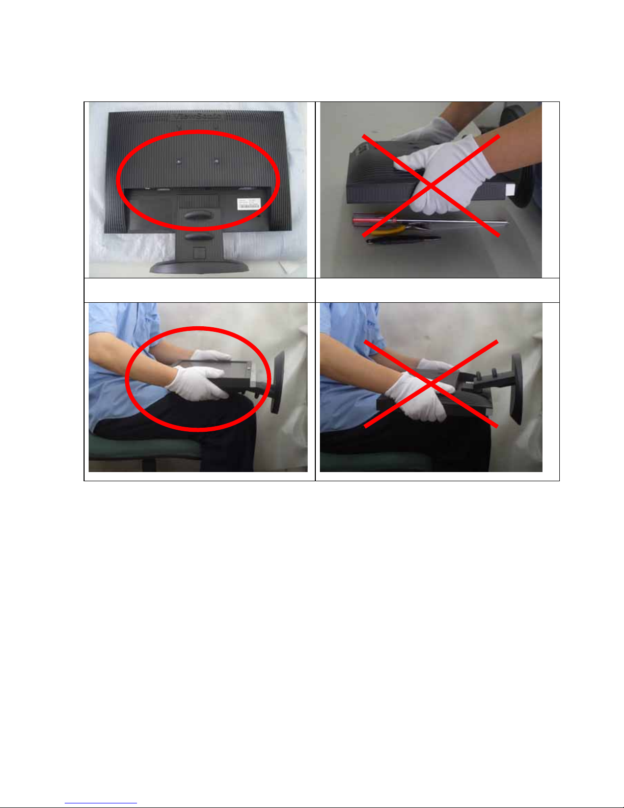
1.4 HANDING AND PLACING METHODS
Correct Methods: Incorrect Methods:
Only touch the metal frame of the LCD panel or
the front cover of the monitor. Do not touch the
surface of the polarizer.
Surface of the LCD panel is pressed by fingers and
that may cause “Mura.”
Take out the monitor with cushions
Taking out the monitor by grasping the LCD panel.
That may cause “Mura.”
Place the monitor on a clean and soft foam pad.
Placing the monitor on foreign objects. That could
scratch the surface of the panel or cause “Mura.”
- 6 –
Place the monitor on the lap, the panel surface
must be upwards.
The panel is placed facedown on the lap. That may
cause “Mura.”
- 7 –
2. Specification
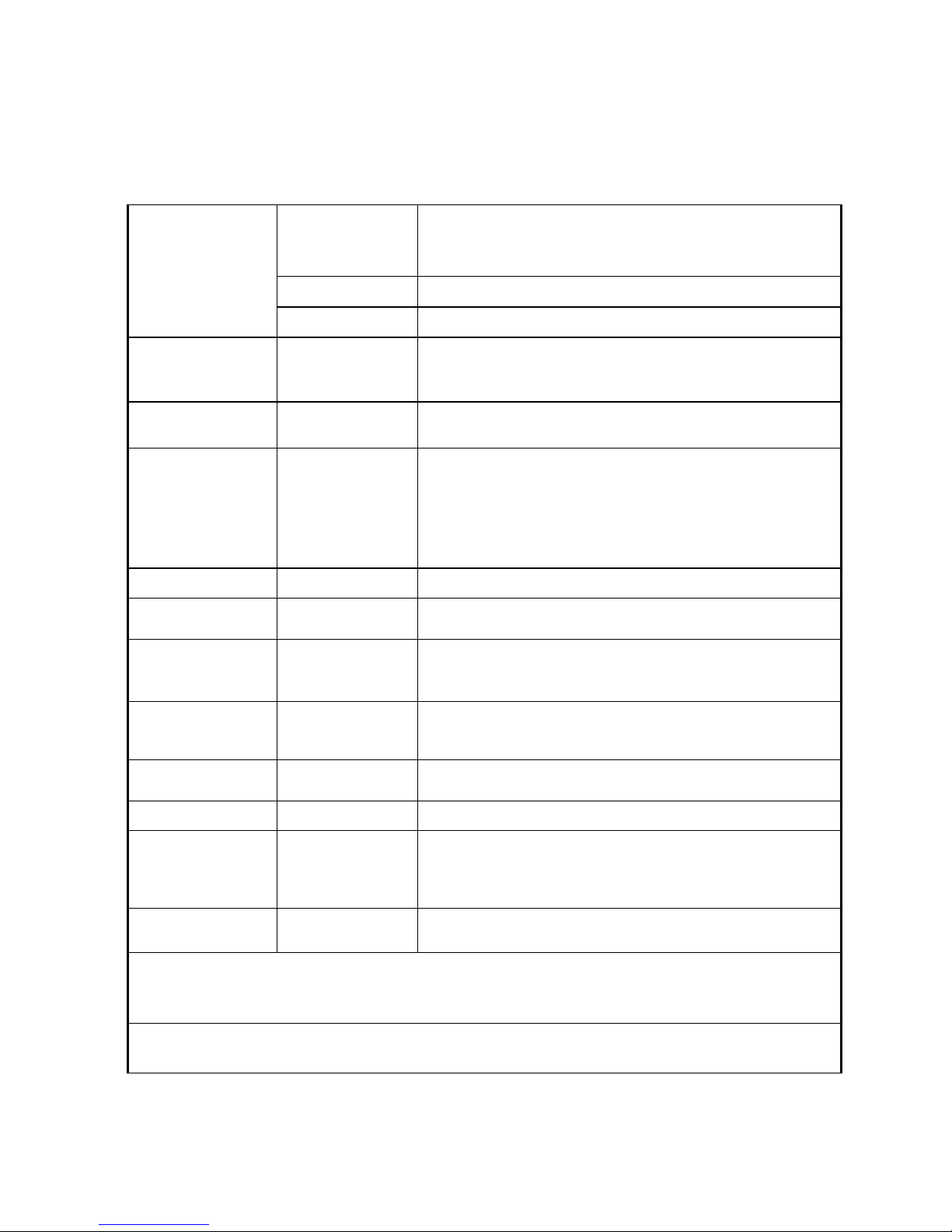
2.1 PRODUCT SPECIFICATIONS
Type
16.0” (full 15.6” wide viewable diagonal area),
TFT(Thin Film Transistor), Active Matrix WXGA lcd,
0.252mm pixel pitch
Color Filter RGB vertical stripe
LCD
Glass Surface Anti-Glare
Input Signal Video Sync
RGB analog(0.7/1.0 Vp-p, 75ohms)
Separate Sync, Fh:24-82 kHz, Fv:50-75 Hz
Compatibility PC
Macintosh
Up to 1366 x 768 Non-interlaced
Power Macintosh up to 1366 x 768
Resolution Recommended
and supported
1366 x 768 @ 60 Hz
1280 x 1024 @ 60 Hz
1024 x768 @ 60, 70, 72, 75 Hz
800 x 600 @ 56, 60, 72, 75 Hz
640 x 480 @ 60, 75 Hz
720 x 400 @ 70 Hz
Power Voltage 100V~240 VAC, 50/60Hz (auto switch)
Display area Full Scan 347.5mm(H) x 196.8mm(V) 13.7”(H) x 7.7”(V)
Operating
conditions
Temperature
Humidity
Altitude
32°F to + 104°F( 0°C to + 40°C)
20%C to + 80%(non-condensing)
To 10,000 feet
Storage conditions
Temperature
Humidity
Altitude
-4°F to + 140°F( -20°C to + 60°C)
5%C to + 90%(non-condensing)
To 40,000 feet
Dimensions Physical
376.23mm(W) x 327.42mm(H) x165mm(D)
14.8”(W) x 12.8”(H) x 5.6”(D)
Weight Physical 5.84 Ib(2.65 kg)
Regulations
BSMI, CCC, PSB, C-Tick, CE, GS, MIC, VCCI,
Ergo, Gost-R/Hygienic, SASO, TCO’03, Ukraine,
UL/cUL, FCC-B, ICES-B, ENERGY STAR
®
TUV-S/IRAM/UL-AR S Mark,
Power saving
modes
On
Off
16W (Typical) (blue LED)
<1W
Preset Timing Mode (pre-adjusted to VESA® 1366 x 768 @ 60 Hz)
Warning: Do not set the graphics card in your computer to exceed these refresh rates; doing so may
result in permanent damage to the LCD display.
1
Macintosh computers older than G3 require a ViewSonic® Macintosh adapter. To order an adapter,
contact ViewSonic.
- 8 –
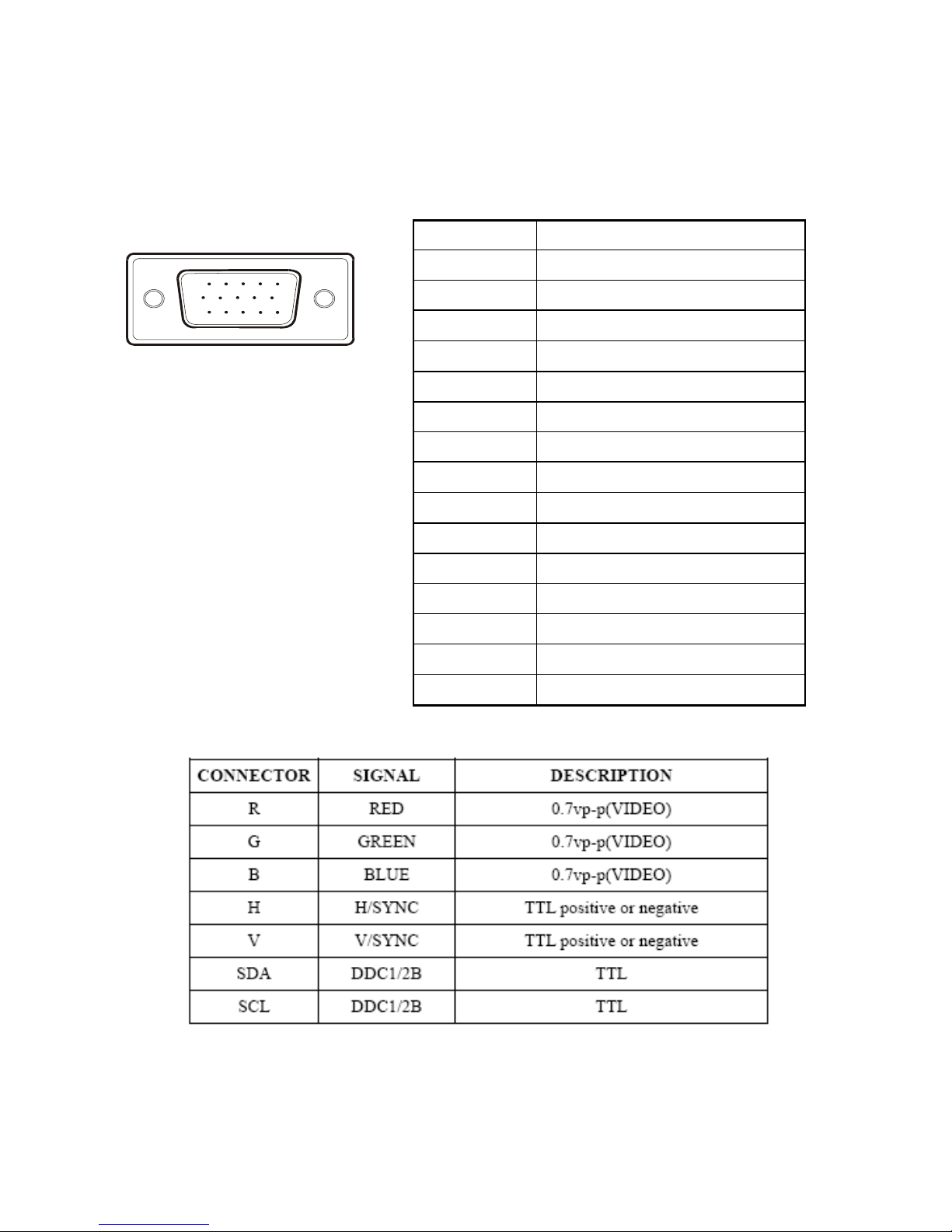
2.2 INTERFACE DESCRIPTION
D-SUB 15 PIN CONNECTOR
15
6
10
11 15
SIGNAL LEVEL
Pin Number Pin Function
1 Red video input
2 Green video input
3 Blue video input
4 No Connection
5 Ground
6 Red video ground
7 Green video ground
8 Blue video ground
9 +5V
10 H/V sync ground
11 No co n ne ction
12 (SDA)
13 Horizontal sync (Composite sync)
14 Vertical sync
15 (SCL)
- 9 –
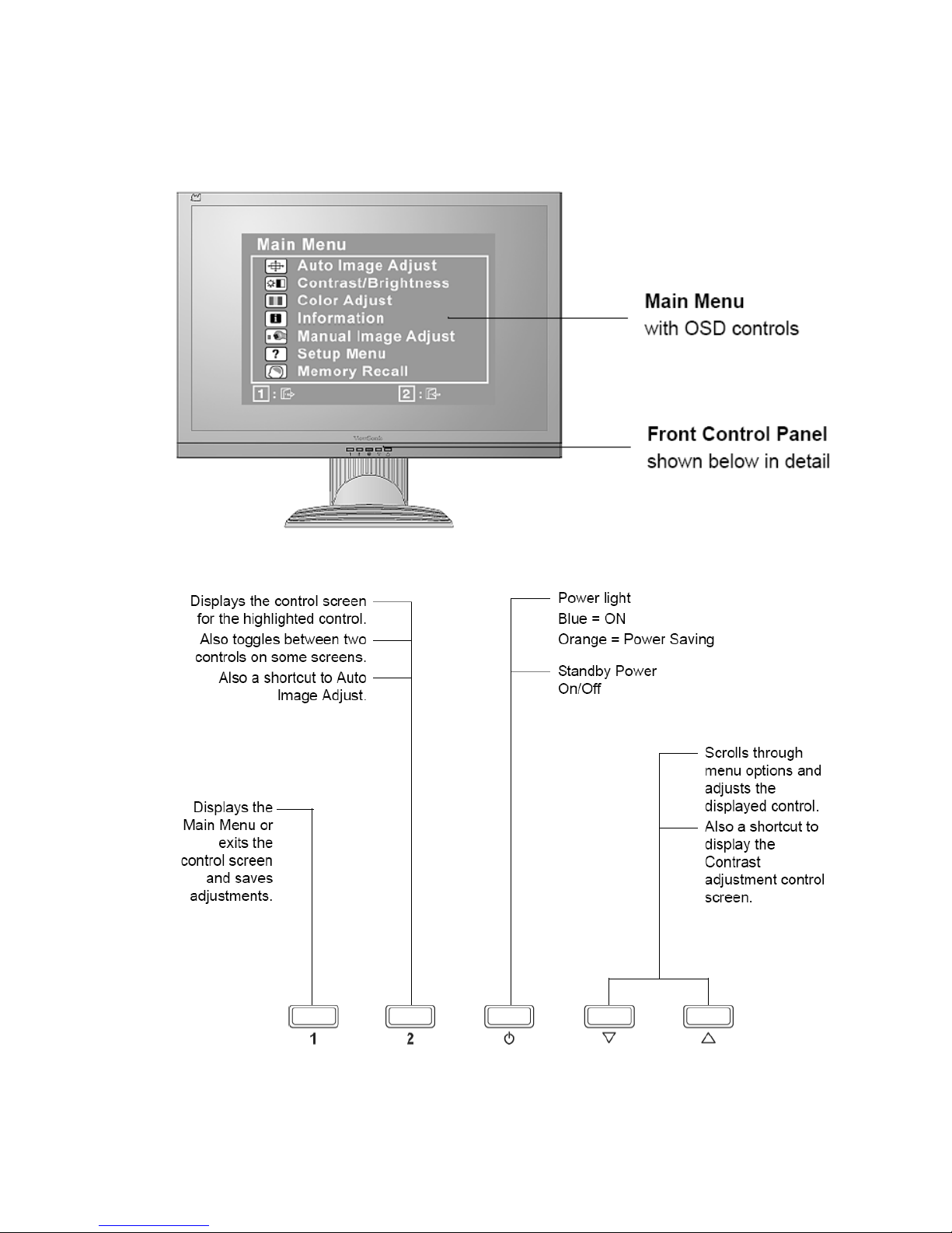
3.Front Panel Function Controls And Indicators
- 10 –
Do the following to adjust the display setting:
1. To display the Main Menu, press button [1].
NOTE: All OSD menus and adjustment screens disappear automatically after about 15
seconds. This is adjustable through the OSD timeout setting in the setup menu.
2. To select a control to adjust, press ▲or ▼ to scroll up or down in the Main Menu.
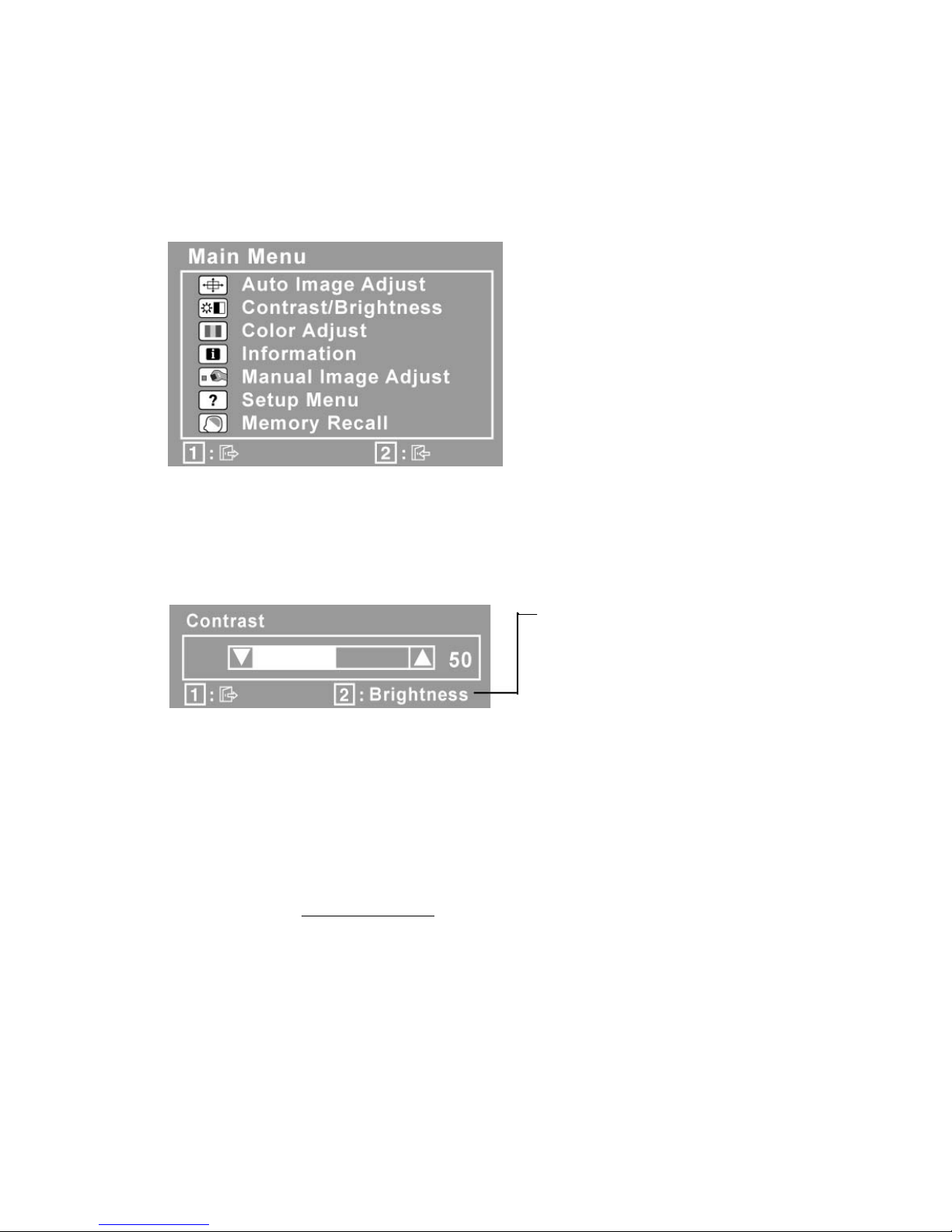
3. After the desired control is selected, press button [2]. A control screen like the one
shown below appears.
The line at the bottom of the screen
shows the current functions of
buttons 1 and 2: Exit or select the
Brightness control.
4. To adjust the control, press the up ▲ or▼ down buttons.
5. To save the adjustments and exit the menu, press button [1] twice.
The following tips may help you optimize your display:
• Adjust the computer's graphics card so that it outputs a 1366 x 768 @ 60Hz video
signal to the LCD display. (Look for instructions on “changing the refresh rate” in the
graphics card's user guide.)
• If necessary, make small adjustments using H. POSITION and V. POSITION until the
screen image is completely visible
. (The black border around the edge of the screen
should barely touch the illuminated “active area” of the LCD display.)
- 11 –
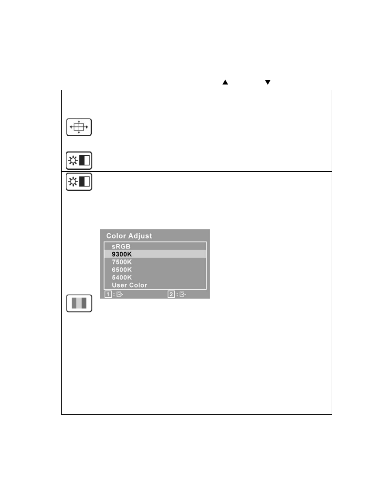
Main Menu Controls
Adjust the menu items shown below by using the up
and down buttons.
Control
Explanation
Auto Image Adjust automatically sizes, centers, and fine tunes the video
signal to eliminate waviness and distortion. Press the [2] button to obtain a
sharper image.
NOTE: Auto Image Adjust works with most common video cards. If this
function does not work on your LCD display, then lower the video refresh rate
to 60 Hz and set the resolution to its pre-set value.
Contrast adjusts the difference between the image background (black level)
and the foreground (white level).
Brightness adjusts background black level of the screen image.
Color Adjust provides several color adjustment modes, including preset color
temperatures and a User Color mode which allows independent adjustment of
red (R), green (G), and blue (B). The factory setting for this product is 6500K
(6500 Kelvin).
sRGB-This is quickly becoming the industry standard for color management,
with support being included in many of the latest applications. Enabling this
setting allows the LCD display to more accurately display colors the way they
were originally intended. Enabling the intended. Enabling the sRGB setting
will cause Contrast and Brightness adjustments to be disabled.
9300K-Adds blue to the screen image for cooler white (used in most office
settings with fluorescent lighting).
6500K-Adds red to the screen image for warmer white and richer red.
5400K-Adds green to the screen image for a darker color.
User Color Individual adjustments for red (R), green (G), and blue (B).
1. To select color (R, G or B) press button [2].
2. To adjust selected color, press
▲ and▼.
Important: If you select RECALL from the Main Menu when the product is
- 12 –
set to a Preset Timing Mode, colors return to the 6500K factory preset.
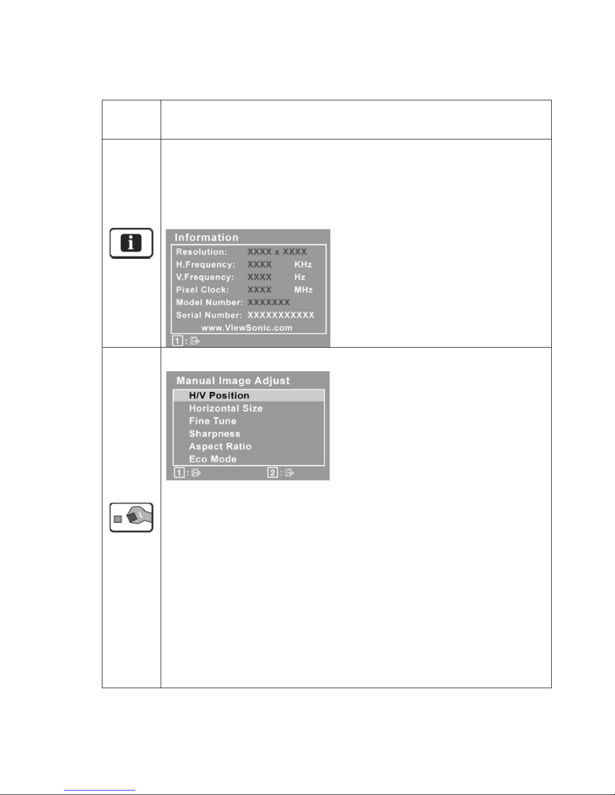
Information displays the timing mode (video signal input) coming from the
graphics card in the computer, the LCD model number, the serial number, and
the ViewSonic
®
website URL. See your graphics card’s user guide for
instructions on changing the resolution and refresh rate (vertical frequency).
NOTE: VESA 1366 x 768 @ 60Hz (recommended) means that the resolution
is 1366 x 768 and the refresh rate is 60 Hertz.
Manual Image Adjust display the Manual Image Adjust menu
H./V. Position (Horizontal/Vertical Position) moves the screen image left or
right and up or down.
H./Size (Horizontal Size) adjusts the width of the screen image.
Fine Tune sharpens the focus by aligning text and/or graphics with pixel
boundaries.
NOTE: Try Auto Image Adjust first.
Sharpness adjusts the clarity and focus of the screen image.
Aspect ratio Selects the image size for 4:3 and full screen.
ECO Mode provides the lower power consumption by reducing the
brightness.
Standard: The default brightness setting.
Optimize: Decreases the brightness by 25%.
- 13 –
Conserve: Decreases the brightness by 50%.
NOTE: When the ECO Mode is set to “Optimize” or “Conserve”, the
Brightness, Contrast, and Dynamic Contrast cannot be adjusted.
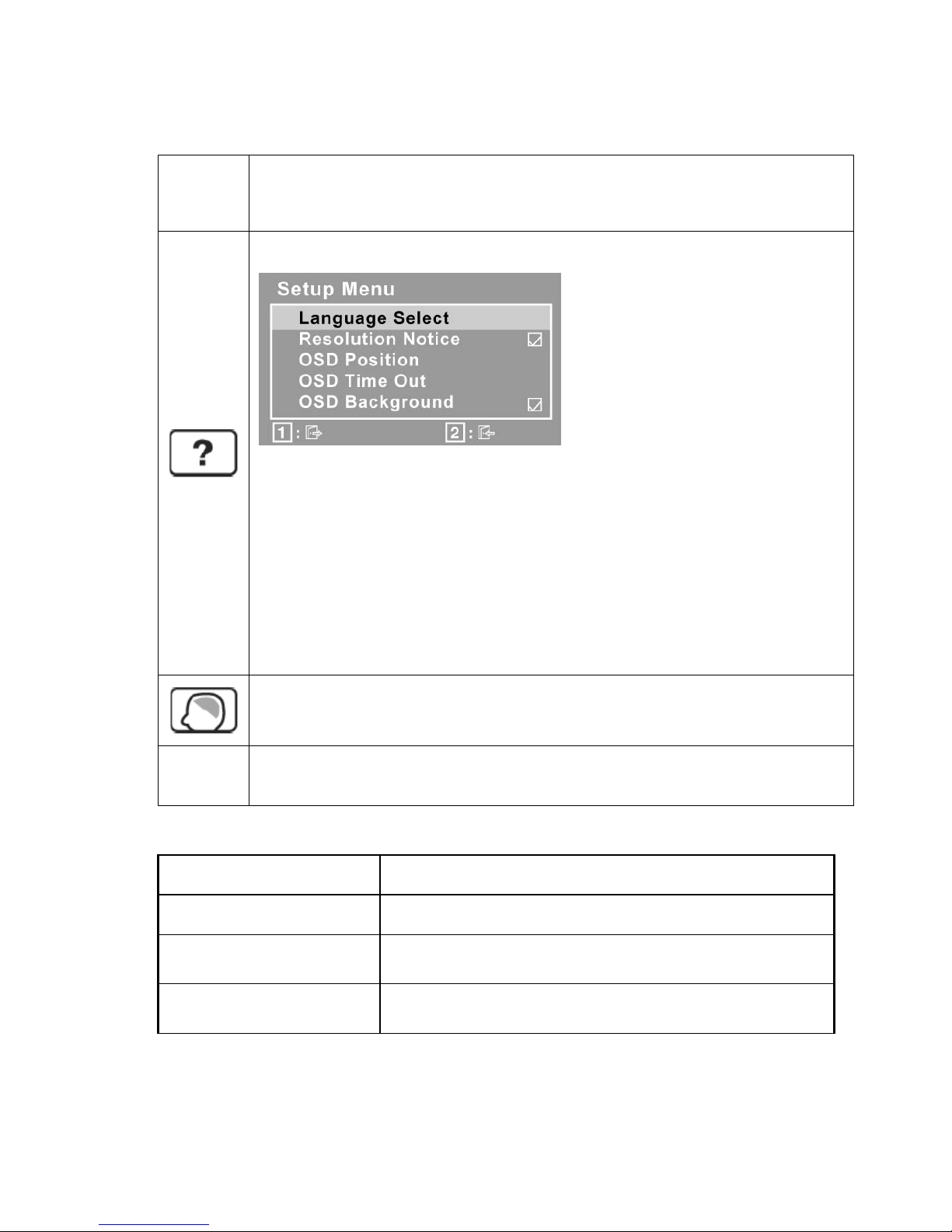
Setup Menu displays the menu shown below:
Language Select allows the user to choose the language used in the menus
and control screens.
Resolution Notice advises the optimal resolution to use.
OSD Position allows the user to move the OSD menus and control screens.
OSD Timeout sets the length of time the OSD screen is displayed. For
example, with a “15 second” setting, if a control is not pushed within 15
seconds, the display screen disappears.
OSD Background allows the user to turn the OSD background On or Off.
Memory Recall returns the adjustments back to factory settings if the display
is operating in a factory Preset Timing Mode listed in the Specifications of this
manual.
Exception: This control does not affect changes made with the User Color
control, Language Select or Power Lock setting.
SHORT CUTS FUNCTION FROM THE BUTTONS
[1]
Main Menu
[2]
Auto Image Adjust
[▼]
To immediately activate Brightness and menu. It should
be change to Contrast OSD by push button[2]
[▲]
To immediately activate Contrast menu. It should be
change to Brightness OSD by push button[2]
- 14 –
[▼] + [▲]
Recall both of Contrast and Brightness to default without
OSD message.
[1] + [2]
Toggle 720x400 and 640x400 mode when input 720x400
or 640x400 mode
[1] + [▼] + [▲]
(Keep pushing 5 sec)
White Balance
1. It will not shown on user’s guide
2. OSD message as below,
(Image = no blanking)
[1] + [▲]
OSD Lock
[1] + [▼] Power Lock
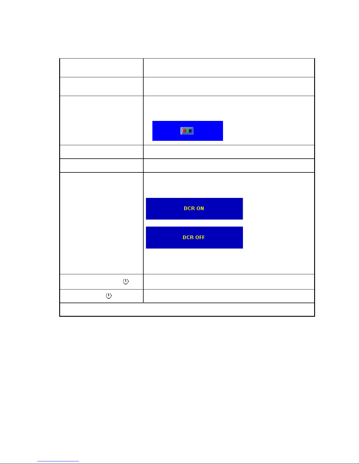
[▲]
1.Long Press [up] key 3 seconds to switch DCR On/Off,
2. Loop: DCR On <=> DCR Off
When switch to DCR ON
When switch to DCR OFF
3. DCR Off in Factory mode.
4. Reset to default when re-power on/off
5. Message will appear only after Hot Key is pressed
No signal + [1] + [ ] Burning mode
[1] + [ ] Factory Mode
Remark : All the short cuts function are only available while OSD off

- 15 –
4. Circuit Description
4.1 LCD MONITOR DESCRIPTION
The LCD MONITOR will contain a Main Board, an Power Board, Key Board which
house the flat panel control logic, brightness control logic and DDC.
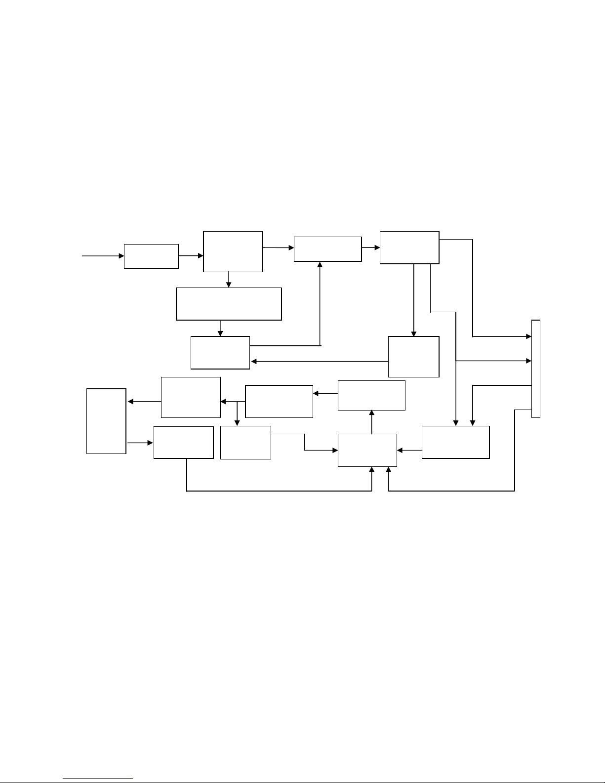
4.2 MAIN BOARD BLOCK FUNCTION DESCRIPTION
The main board contains panel control logic, brightness control logic, DDC and DC convert
DC circuit and so on.
Power Board
(Include: adapter, inverter)
Flat Panel and
CCFL backlight
Main Board
Key Board
RS232 Connector
For white balance
adjustment in factory
mode
HOST Computer
CCFL Drive.
AC-IN
100V-240V
Video signal, DDC
Monitor Block Diagram
R
G
B
H
V
SDA
SCL
OSC
Backlight and Panel
PWPC board
Flash memory
Keyboard
TSUM1PFR-LF
- 16 –
4.3 PWPC BOARD BLOCK FUNCTION DESCRIPTION
PWPC board combines to adapter and inverter, Adapter which commonly consists of
bridge rectifier and filter, start circuit, PWM control circuit, protection circuits and convert
to 12V, 5V DC voltage by input 90V-240V AC voltage that provide power supply for each
chips in the main board and inverter. Inverter is DC TO AC circuit. It changes the 12v
DC of power supply to about 600-800v AC that drives the backlight. It mostly consists of
starting circuit, PWM controller, DC changing circuit, LC surging circuit, output circuit
and protection circuit etc.
AC input
EMI filter
Bridge
Rectifier
and Filter
Start Circuit
R904, R932, R933
PWM
Control IC
Over
Vol tage
Protect
Rectifier
CMOS
ON/OFF
Control
PWM
Control IC
Feedback
Circuit
OSC and
Output
Circuit
DC Convert
Circuit
MOSFET
Q802
Over
Voltage
CN902
Transformer
Lamp
5V
12V
ON/OF
DIM

- 17 –
4.4 INTRODUCTION OF IC
TSUM1PFR-LF(U401): integrate ADC, OSD, SCALER, MCU, LVDS, convert analog
RGB into digital and room and shrink scaling output to LCD panel.
PIN Function:
Pin Symbol Description
21 SDO SPI flash serial data output
22 CSZ SPI flash chip select
23 SCK SPI flash serial select
24 SDI SPI flash serial data input
18 DDCA_SDA/RS232_TX DDC Data for analog interface/
UART Ttransmitter /
General Purpose Input/Output; 4mA driving strength
19 DDCA_SCL/RS232_RX DDC Clock for analog interface/
UART Receiver /
General Purpose Input/Output; 4mA driving strength
54 RST Chip reset; High reset
52 VCTRL Regulator control
16 HSYNCO Analog HSYNC input
17 VSYNCO Analog VSYNC input
15 REFP Internal ADC top de-coupling pin
14 REFM Internal ADC bottom de-coupling pin
4 REXT External resistor 390 ohm to AVDD_33
Chip Configuration Input
MODE[1:0] Chip Operation
32、31 MODE[1:0]
Input
00 Normal Operation
1 XIN Xin; Crystal Oscillator Input
2 XOUT Xout; Crystal Oscillator Output
6
AVDD_33
ADC Power 3.3V
51 VDDP Digital Output Power 3.3V
30、53
VDDC Digital Core Power 1.8V
3、5、29
GND Ground

- 18 –

- 19 –
AP1117D33LA(U404): DC power convert, convert to 3.3v.
SST25LF020A-33-4C-SAE(U403): SST’s serial flash family features a four-wire,
SPI-com-patible interface that allows for a low pin-count package occupying less board
space and ultimately lowering total system costs. The SST25LF020A/040A devices
significantly improve performance, while lowering power consumption. The total energy
consumed is a function of the applied voltage, current, and time of application. The
SST25LF020A/040A devices operate with a single 3.0-3.6V power supply. The
SST25LF020A devices are offered in an 8-lead SOIC 150 mil body width (SA) package.
Pin Diagram:
PIN Descriptions:

- 20 –
Circuit Diagram
Symbol Pin Name Functions
SCK Serial Clock
To provide the timing of the serial interface.
Commands, addresses, or input data are latched on the
rising edge of the clock input, while output data is shifted out
on the falling edge of the clock input.
SI
Serial Data
Input
To transfer commands, addresses, or data serially into the
device.
Inputs are latched on the rising edge of the serial clock.
SO
Serial Data
Output
To transfer data serially out of the device.
Data is shifted out on the falling edge of the serial clock.
CE# Chip Enable
The device is enabled by a high to low transition on CE#.
CE# must remain low for the duration of any command
sequence.
WP# Write Protect
The Write Protect (WP#) pin is used to enable/disable BPL
bit in the status register.
HOLD# Hold
To temporarily stop serial communication with SPI flash
memory without resetting the device.
VDD Power Supply To provide power supply(3.0-3.6V)
VSS Ground

- 21 –
LD7552BPS (IC901): PWM control, high-voltage startup current. The circuit unit has
functions such as over-current protection, over-voltage protection, output short-circuit
protection and etc. The function of each pin and the inside circuit diagram are as follows:
Pin Name Function
1 GND Ground
2 COMP
Voltage feedback pin (same as the COMP pin in UC384X), By
connecting a photo-coupler to close the control loop and achieve the
regulation
3 VCC Supply voltage pin
4 RT
This pin is to program the switching frequency. By connecting a resistor
to ground to set the switching frequency.
6 NC Unconnected pin
7 VCC Supply voltage pin
8 OUT Gate drive output to drive the external MOSFET
- 22 –
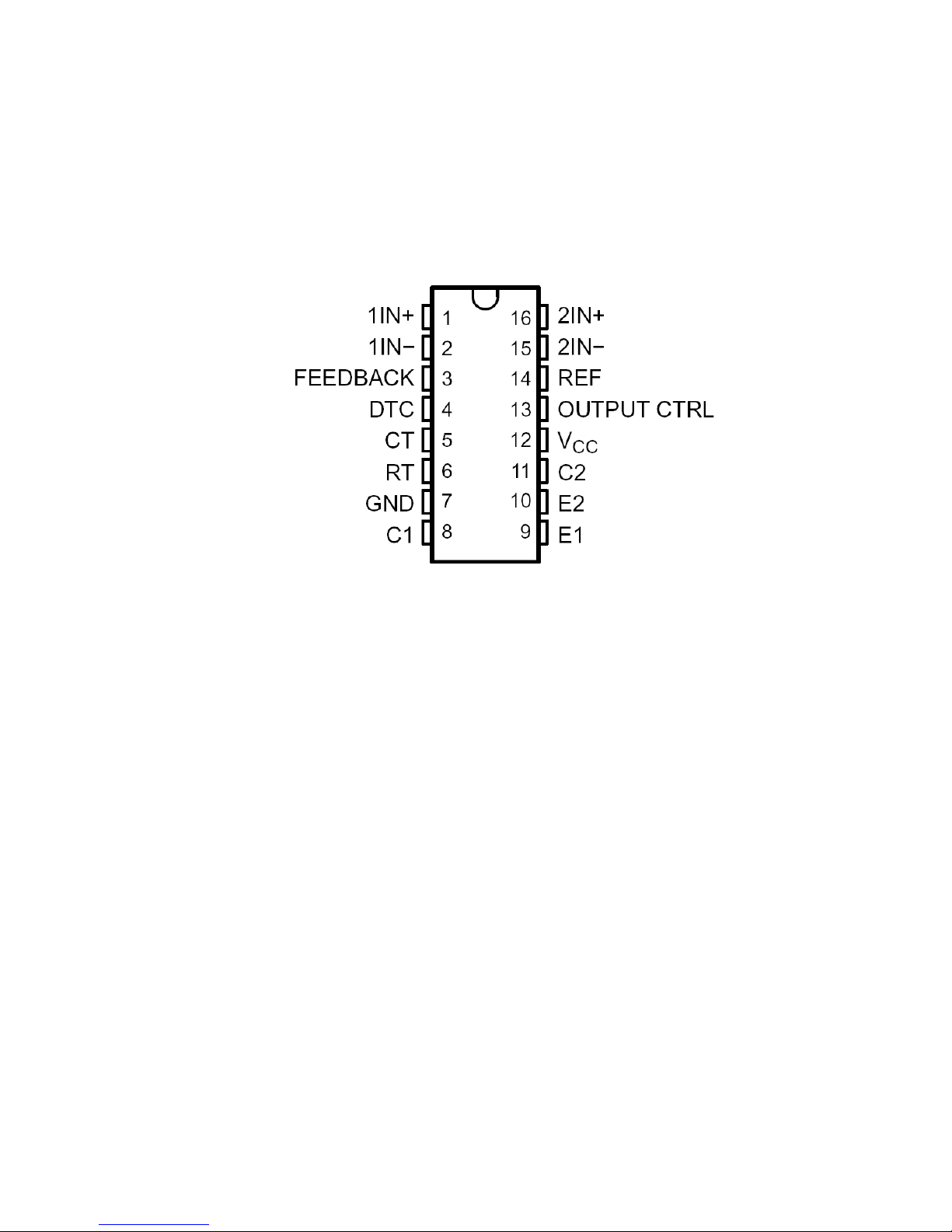
TL494(IC801): The TL494 incorporates all the functions required in the construction of a
pulse-width-modulation (PWM) control circuit on a single chip. Designed
primarily for power-supply control, this device offers the flexibility to tailor the
power-supply control circuitry to a specific application.
PIN Descriptions:
 Loading...