

Page 1

SD-T225/SD-T245
ViewSonic Device Manager Pro
User Guide
Page 2

1
Copyright and Trademark Statements
© 2015 ViewSonic Corporation. All rights reserved.
This document contains proprietary information that is protected by copyright. No part of this
document may be photocopied, reproduced, or translated to another language without the prior
written consent of ViewSonic Corporation.
Limitation of Liabili ty
While reasonable efforts have been made to ensure the accuracy of this manual, the manufacturer
and distributor assume no liability resulting from errors or omissions in this manual , or from the use of
the information contained herein.
Trademark statements
Microsoft and Windows are trademarks of the Microsoft group of companies.
Citrix, ICA, and XenApp are trademarks of Citrix Systems, Inc. and/or one or more of its subsidiaries,
and may be registered in the United States Patent and Trademark Office and in other countries.
VMware and VMware View are trademarks or registered trademarks of the VMware, Inc.
GraphOn and GO-Global are registered trademarks and the GO logo is a trademark of GraphOn
Corporation.
The Firefox logo is a registered trademark of Mozilla Foundation or Mozilla Corporation.
Adobe and Adobe Reader are either registered trademarks or trademarks of Adobe Systems
Incorporated in the United States and/or other countries.
Other product names mentioned herein are used for identification purposes only and may be
trademarks and/or registered trademarks of their respective companies.
Page 3

2
Table of Contents
Copyright and Trademark Statements ............................................................................................ 1
Table of Contents ............................................................................................................................. 2
Acronyms and Abbreviations .......................................................................................................... 5
Convention Types ............................................................................................................................. 6
Global Declaration ............................................................................................................................ 6
Chapter 1 ........................................................................................................................................... 7
VDM Pro Smart Client Management Suite ...................................................................................... 7
VDM Pro Base Framework - Introduction ..................................................................................... 7
System Requirements ................................................................................................................. 8
Chapter 2 ........................................................................................................................................... 9
VDM Pro Base Framework Installation ............................................................................................ 9
Chapter 3 ......................................................................................................................................... 17
Getting Started ... .......................................................................................................................... 17
Start VDM Pro Service ............................................................................................................... 17
Stop VDM Pro Service ............................................................................................................... 17
Login VDM Pro Application ........................................................................................................ 17
Logout VDM Pro Application ...................................................................................................... 18
Chapter 4 ......................................................................................................................................... 19
VDM Pro Welcome Dialog ............................................................................................................. 19
Quick Tips ................................................................................................................................. 19
Shortcuts ................................................................................................................................... 19
Chapter 5 ......................................................................................................................................... 20
VDM Pro GUI Layout..................................................................................................................... 20
Chapter 6 ......................................................................................................................................... 21
VDM Pro Configuration ................................................................................................................. 21
Discovery Configuration ............................................................................................................. 22
Messaging Window .................................................................................................................... 26
SSL Upload ............................................................................................................................... 27
VDM Pro Users .......................................................................................................................... 28
Language Selection ................................................................................................................... 32
Chapter 7 ......................................................................................................................................... 33
VDM Pro Tools ... .......................................................................................................................... 33
VDM Pro Reports Framework .................................................................................................... 33
Retrieving VDM Pro Server Events ............................................................................................ 39
Downloading VDM Pro Logs ...................................................................................................... 41
Messaging Actions ..................................................................................................................... 42
Page 4

3
Chapter 8 ......................................................................................................................................... 44
Device List Operation .................................................................................................................... 44
Node Management Group ......................................................................................................... 45
Device Options .......................................................................................................................... 45
Messaging Console Options ...................................................................................................... 45
Category Summaries ................................................................................................................. 46
IP Management Group .............................................................................................................. 47
Chapter 9 ......................................................................................................................................... 49
About VDM Pro .. .......................................................................................................................... 49
View VDM Pro Information ......................................................................................................... 49
Generate Debug Report............................................................................................................. 50
Chapter 10 ....................................................................................................................................... 51
Smart Client Management (SCX) .................................................................................................. 51
Introduction ................................................................................................................................ 51
Hardware Requirement .............................................................................................................. 51
System Requirement for Installing SCX ..................................................................................... 52
Supported Operating Systems for Installing SCX ....................................................................... 52
Security ..................................................................................................................................... 52
Compatibility .............................................................................................................................. 52
Chapter 11 ....................................................................................................................................... 53
Smart Client Management Configuration ....................................................................................... 53
Viewing Smart Client Management Page ................................................................................... 53
Group Management ................................................................................................................... 55
Firmware Manager ..................................................................................................................... 56
Quick Connection P olic y Manager ............................................................................................. 62
Connection Manager ................................................................................................................. 66
Managing Client Policies............................................................................................................ 70
Quick Connection ...................................................................................................................... 75
Connection Manager ................................................................................................................. 76
Client Setup ............................................................................................................................... 77
Password Setting ....................................................................................................................... 78
SCX Tools .......... .......................................................................................................................... 78
Power Control ............................................................................................................................ 78
VNC Connector ......................................................................................................................... 79
Send Message ........................................................................................................................... 80
Certificate Upload ...................................................................................................................... 80
Firmware Update ....................................................................................................................... 81
General Information ...................................................................................................................... 82
Page 5

4
Chapter 12 ....................................................................................................................................... 84
Appendix ............ .......................................................................................................................... 84
Event Logs ................................................................................................................................ 84
Page 6
5
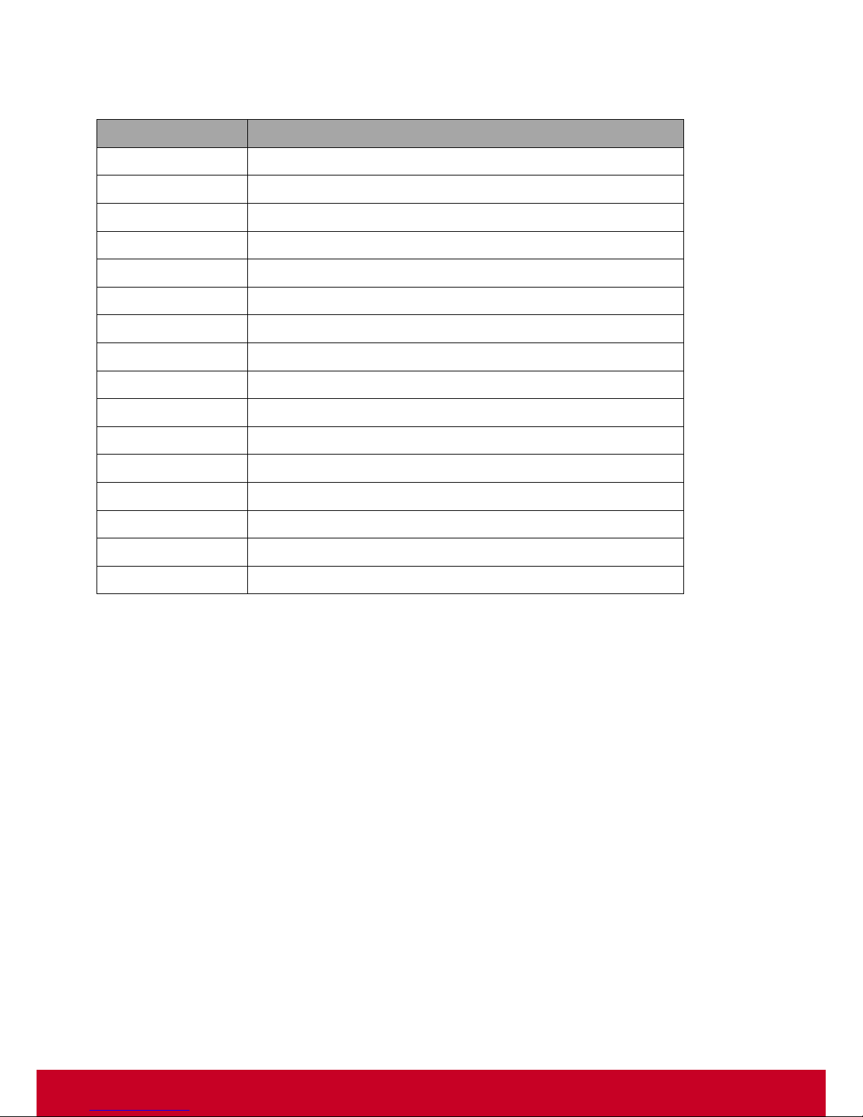
Acronyms an d Abbreviations
Acronyms
Abbreviations
CIM
Common Information Model
DN
Domain Name
DNS
Domain Name Server
GUI
Graphical User Interface
IP
Internet Protocol
KVM
Kernel-based Virtual Machine
LDAP
Lightweight Directory Access Protocol
OS
Operating System
PRN
Purchase Reference Number
SCX
Smart Client Management
SNMP
Simple Network Management Protocol
SSL
Secure Sockets Layer
TLS
Transport Layer Security
VNC
Virtual Network Computing
WSMAN
Web Services for Management
VDM Pro
ViewSonic Device Manager Pro
Page 7
6
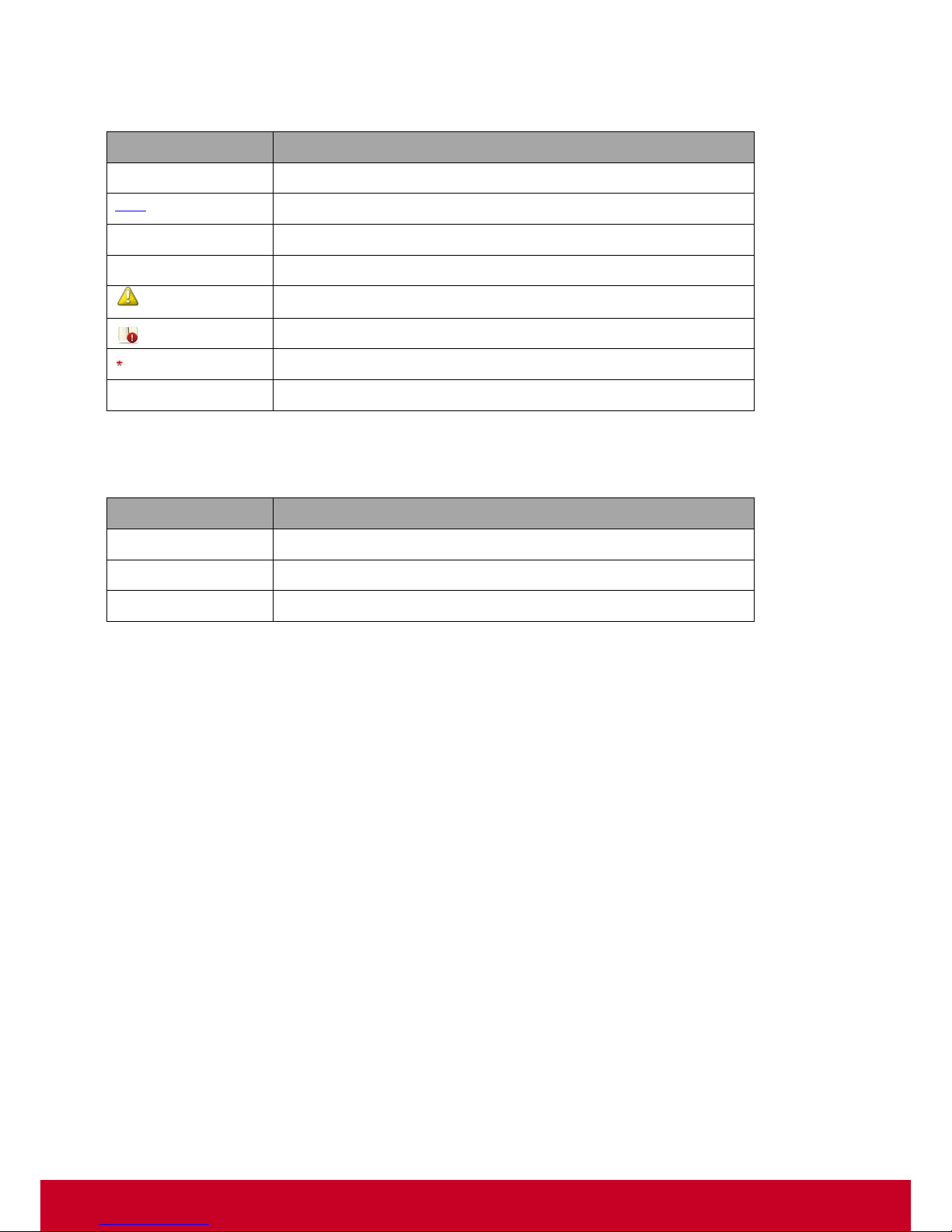
Convention Ty pes
Types
Usage
Text
Button Names, Text Boxes, Labels
Text
Hyperlink
“Text”
Cross Reference
Text
Code
Note
Remember
Mandatory field
Text
Refer
Global Declaration
Button
Usage
Cancel
Cancel the current process and return to the previous screen
Back
Go back to the previous screen
Close
Exit from the current screen
Page 8

7
Chapter 1
VDM Pro Smart Client Managemen t Suite
VDM Pro Base Framewor k - Introduction
VDM Pro is an ViewSonic Device Manager Pro that provides centralized management of systems
deployed in a network. Organized as a plug-in framework, VDM Pro provides device specific
management features for individual plug-ins.
Following are the VDM Pro plug-ins:
Smart Client Management (SCX) is a thin client management plugin for VDM Pro that provides
aggregated management of thin client devices equipped with ViewSonic thin client agents. SCX will
provide remote manageability of the system.
VDM Pro uses industry standard protocols and completely provide remote manageability. VDM Pro
provides a browser agnostic and intuitive web interface that allows an administrator to manage the
devices by using any standard web browser. In addition, VDM Pro also supports CIM-XML, WSMAN
and SSH for remote manageability.
Page 9
8
System Requirements
Minimum hardware and software requirements for installing VDM Pro are as follows:
Hardware Requirements
System Processor: 2 GHZ
System Memory: 4 GB RAM
Free Disk Space: 10 GB (May need more disk space depending on the nodes managed and
the amount of history information needed)
Note: The minimum system requirements listed above can support up to 200 devices. The VDM Pro
software is capable of managing up to 10,000 clients and licenses.
Software requirements
Browser:
Internet Explorer 7 or later
Mozilla Firefox 3.5 or later
Google Chrome 5.0 or later
Operating System:
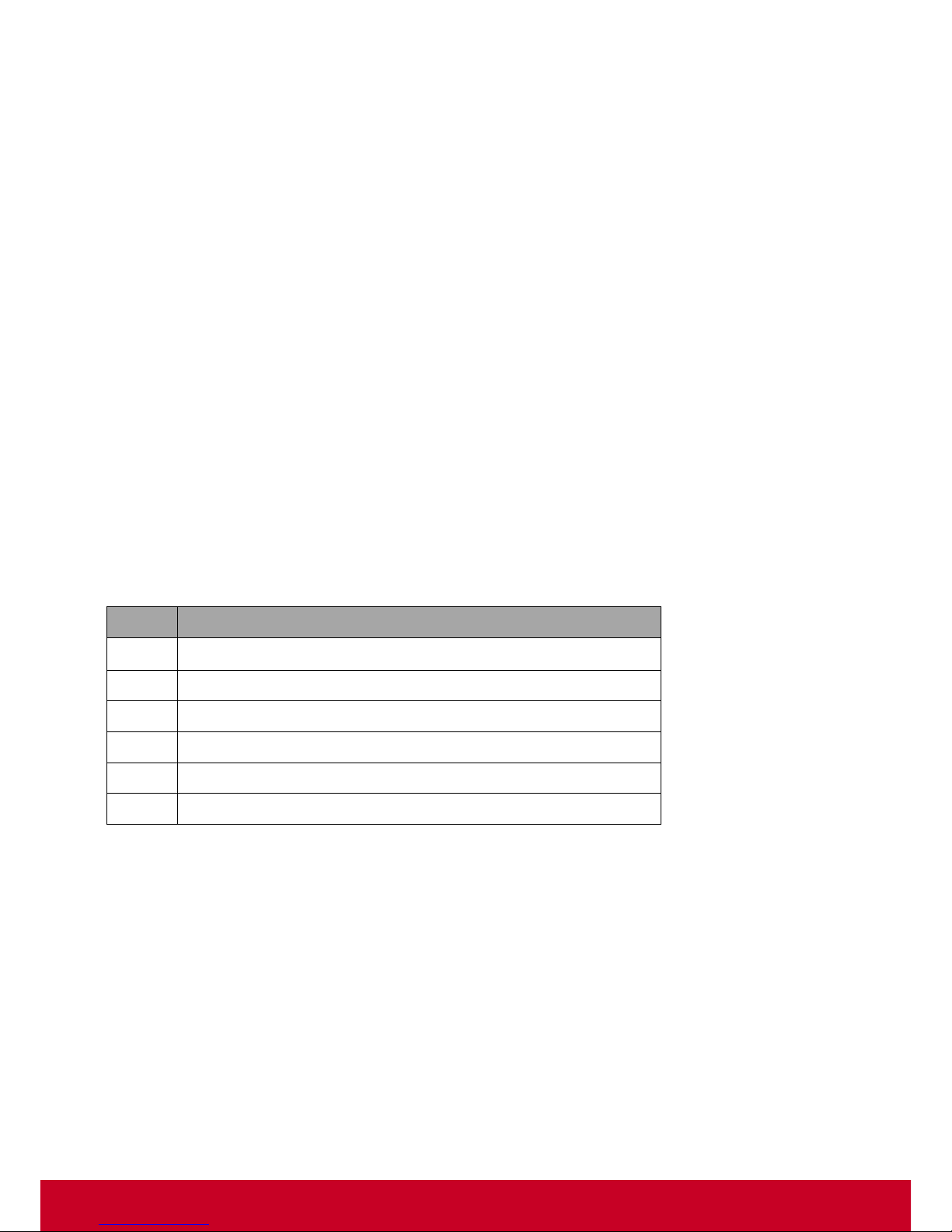
The details of VDM Pro installable OS are shown in a table below.
S.No
VDM Pro Installable OS
1
Windows 7 Enterprise – 32 bit
2
Windows 7 Enterprise – 64 bit
3
Windows Server 2008 R2 Standard - 64 bit
4
Windows 7 Ultimate – 32 bit
5
Windows 2012 Server
6
Windows 8
Port requirements
VDM Pro requires ports 80/443 (http), 2121 (FTP), 50000 (Agent). Make sure no other application is
using these ports.
Page 10
9
Chapter 2
VDM Pro Base Framework Installati on
VDM Pro installation includes install and uninstall actions for Windows operating system.
For Windows
Installing VDM Pro
1. Uninstall the old version of VDM Pro, if available. This step is for clean installation.
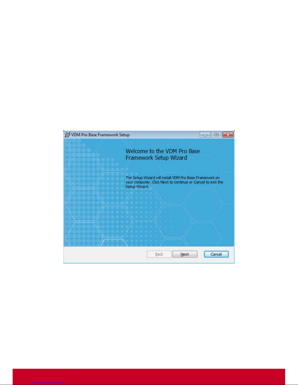
2. Right click the VDM Pro.client-3.0-xxxxxx-win32-x86.exe and click Run as Administrator. An
Extracting window appears for displaying the progress stage and then VDM Pro Base
Framework Setup dialog box appears as displayed in the subsequent screenshot.
Figure 1: Setup
Page 11

10
3. Click Next to continue. This action opens Destination Folder section in the same dialog box as
displayed in the subsequent screenshot.
Figure 2: Destination Folder
4. Click Next to continue installation in the default folder, (Or) click Change to choose another folder.
By clicking Next button, the install options appear in the Setup dialog box.
Page 12
11
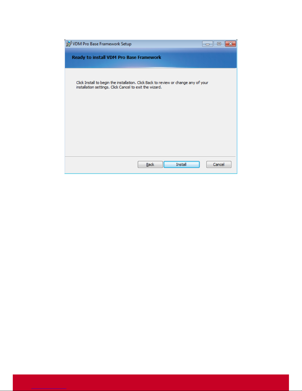
5. Click Install button to start the insta lla tion process. Click Back to review or change the installation
settings. Click Cancel to exit the wizard. A related screenshot is displayed below.
Figure 3: VDM Pro Installer Notification
Page 13

12
6. Installation process is started by clicking Install button. A related screenshot is shown below.
Figure 4: Installation Process
7. Click Finish to exit the Setup Wizard as shown in the subsequent screenshot.
Figure 5: Installation – Finish
Page 14
13
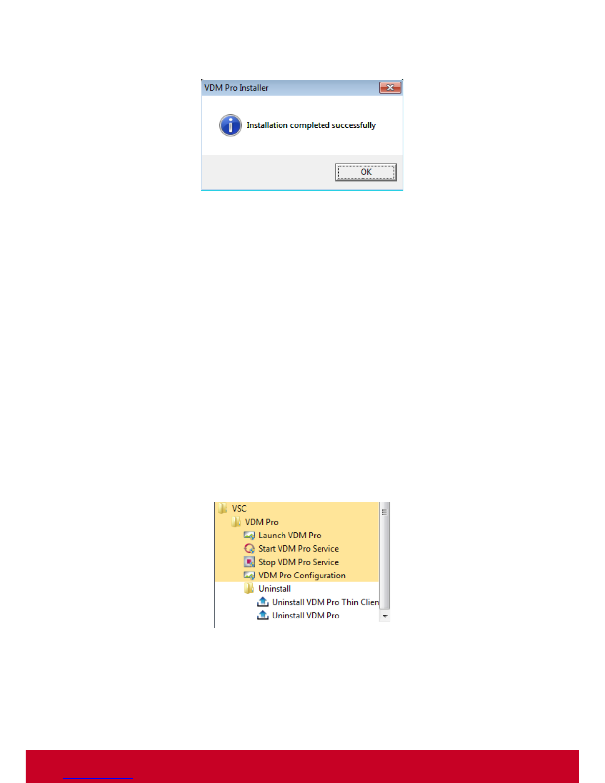
8. Once the installation is successfully completed, VDM Pro Installer dialog box appears to display
the successful installation.
Figure 6: Installation Complete
Uninstalling VDM Pro
Before uninstalling VDM Pro, the user has to follow the steps given below:
• Close all the instances of VDM Pro application and make sure that no files within the VDM Pro
installation folder are opened in the external editors.
• Stop the service from Start menu. Go to Start > All Programs > VDM Pro > VDM Pro > Stop
Service. This is required for making a clean un-installation. For more information on how to stop
the service, see “Stop VDM Pro Service”.
There are two ways to uninstall VDM Pro. They are as follows:
Uninstalling from Start Menu (Recommended)
1. In Window 7, go to Start > All Programs > VSC > VDM Pro > Uninstall folder to uninstall VDM
Pro.
2. (OR) In Windows 8, enter uninstall VDM Pro in Search text box, and then click Uninstall VDM
Pro appears in the screen to uninstall the VDM Pro.
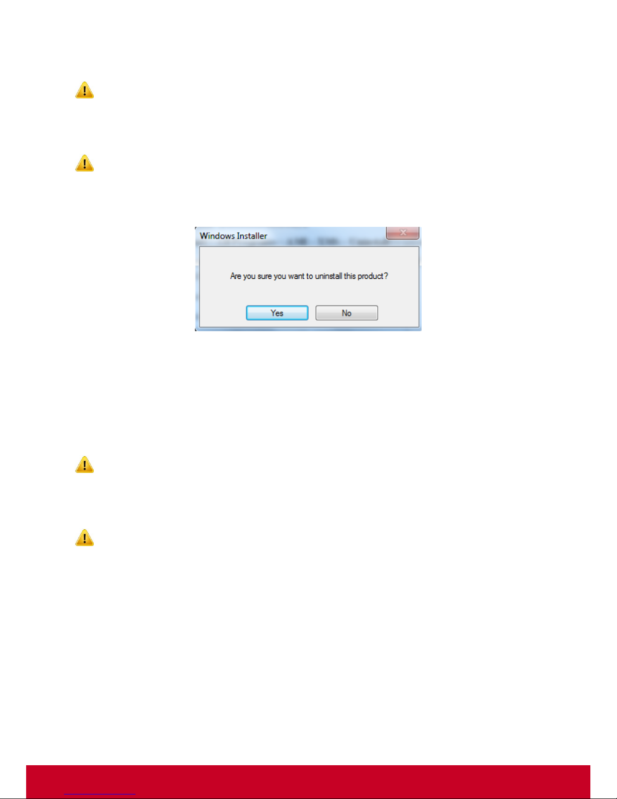
3. Clicking Uninstall folder displays Uninstall VDM Pro and Uninstall VDM Pr o icons. A related
screenshot is displayed below.
Figure 7: Unins tall
Page 15
14
4. Click Uninstall VDM Pro icon to start un-installation process only for VDM Pro. Base Framework
will be available in the machine.
The installer will automatically uninstall only the client management suite without uninstalling
Base.
5. (Or) click Uninstall VDM Pro icon to start un-installation process for entire VDM Pro in the
machine and removes Client Management Suite too.
Wait until VDM Pro is uninstalled completely. The installer will automatically uninstall the client
management suite installed with the Base Framework installation.
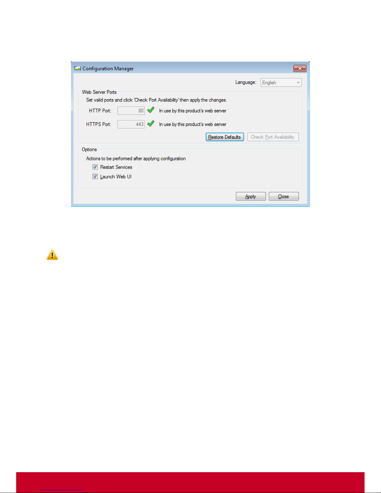
6. A confirmation message box appears to confirm the un-installation. Click Yes to begin the
uninstall action. A related screenshot is displayed below.
Figure 8: Windows Installer
Uninstalling from Control Panel
1. Go to Start > Control Panel > Programs and Features.
2. Select VDM Pro Base Framework from the list and right click on it and select uninstall. This
starts the un-installation process for entire VDM Pro in the machine and removes Client
Management Suite too.
Wait until VDM Pro is uninstalled completely. The installer will automatically uninstall the client
management suite installed with the Base Framework installation.
3. (OR), select VDM Pro and click Uninstall to start un-installation process only for Client
Management Suite. Base Framework will be available in the machine.
The installer will automatically uninstall the client management suite only without uninstalling the
Base framework.
Page 16
15
Configuring VDM Pro at the End of Installation
At the end of the installation process, an VDM Pro Configuration window appears as shown in the
subsequent screenshot.
Figure 9: VDM Pro Configuration – Installation
The web server ports section displays the availability of default web server ports.
In HTTP Port, 80 is set as the default port during installation.
In HTTPS Port, 443 is set as the default port during installation.
1. Click Check Port Availability button to check the port availability before applying the settings.
2. Select the other options such as Restart Services and Launch Web UI as per the need. (This
step is optional).
Page 17

16
3. Click Apply to save the entered settings successfully. VDM Pro Configuration dialog appears as
shown in the subsequent screenshot. The Saving Configuration process may take a few minutes
to complete. VDM Pro will get launched in a web browser, when Start Services and Launch UI
Options are chosen.
Figure 10: VDM Pro Configuration
4. Click OK to complete the installation.
Configuring VDM Pro after Installation
VDM Pro configuration can be done anytime even after the installation.
1. Click Start > All Programs > VSC > VDM Pro > VDM Pro Configuration as shown in the
screenshot below.
Figure 11: Launch VDM Pro Configuration
2. Follow the steps given above in ‘‘Configuring VDM Pro at the end of installation’’.
Page 18
17
Chapter 3
Getting Started
To get started with the VDM Pro application, the user has to perform the following steps:
• Start the VDM Pro service from Start menu. For more information on how to start the service, see
“Start VDM Pro Service”.
• Open a browser and type http://127.0.0.1/launch.html
in the address bar or double click icon
in the Windows desktop to open VDM Pro login page.
• Login the VDM Pro application by using default user name and password. For more information on
how to log in, see “Login VDM Pro Application”.
Start VDM Pro Service
Before logging into the VDM Pro application, the user has to start the service if it is not automatically
started.
For Windows:
Go to Start > All Programs > VSC > VDM Pro > Start VDM Pro Service. This opens the command
prompt, where it displays all the background processes and waits until the command prompt
disappears.
Stop VDM Pro Service
Before uninstalling the VD M Pro application, the user has to stop the services that are running.
For Windows:
Go to Start > All Programs > VSC > VDM Pro > Stop VDM Pro Service. This opens the command
prompt, where it displays all the background processes. Wait until the command prompt disappears.
Login VDM Pro Application
To log into the VDM Pro application, the user has to follow the steps given below:
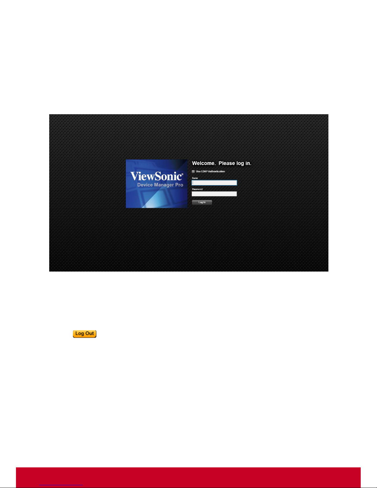
1. Enter the name of the user in Name text box. The user name can be either in al phabets or in alpha
numerals.
2. Enter the user password in Password text box.
The default user name and password is shown below.
Field
Default
User Name
admin
Password
password
Default user name and password must be in lower-case characters. It is advised that once you
log in, the user must change the “admin” password.
Page 19
18
The VDM Pro Users can create a new user name and password to login to the VDM Pro application.
For more details, see “Configuring User”.
3. Click Log In to log in the VDM Pro application.
4. Enable Use LDAP Authentication checkbox to login using LDAP credentials that has been
configured. If an LDAP setting is not configured, a warning message “The LDAP Server is not
configured” will be displayed.
A sample Login screenshot is shown below.
Figure 12: Login
Logout VDM Pro Application
To logout of the VDM Pro application:
1. Click button on the top right corner of the VDM Pro application. A confirmation message
is displayed.
2. Click Yes to log out of the VDM Pro application or click No to return to the previous screen.
Page 20
19
Chapter 4
VDM Pro Welcome Dialog
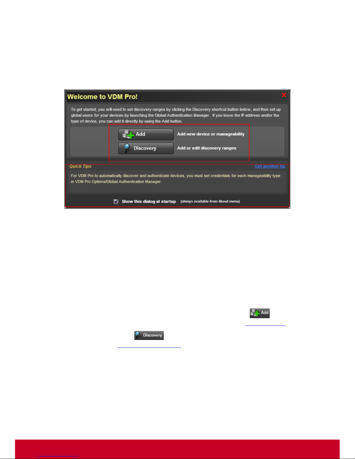
Once logged into VDM Pro, a Welcome Dialog appears as shown in the screenshot below.
Figure 13: Welcome to VDM Pro
Quick Tips
The Welcome Dialog includes quick tips for the users. To view more tips, click Get another tip. To
enable the Welcome Dialog at the startup of VDM Pro, select Show this dialog at startup. The
Welcome dialog can be accessed by another way; click About > Show Welcome Dialog.
Shortcuts
To get started, the user has to set discovery ranges and create global users for the devices. The
Welcome Dialog provides shortcuts to set discovery ranges, create global users and to add IP
address or the type of manageability.
1. To add a new device by the IP address or the type of manageability, click Add new
device or manageability. To know more about discovery ranges, refer “Device Options
”.
2. To set discovery ranges, click Add or edit discovery ranges. To know more about
discovery ranges, refer “Discovery Configuration
”.
Page 21
20
Chapter 5
VDM Pro GUI Layout
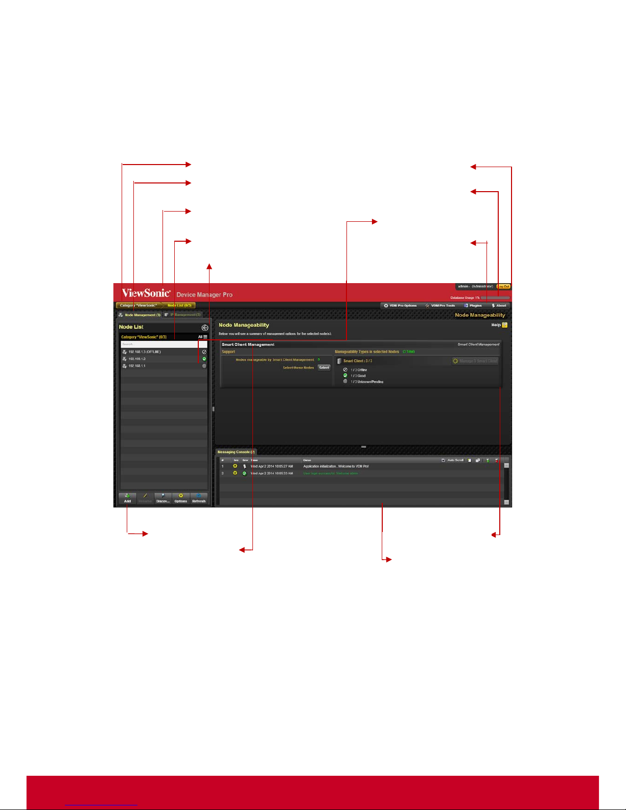
The following screenshot explains the layout of VDM Pro:
Figure 14: VDM Pro Layout
Device Details Window
Breadcrumbs
Node Categories List
Top Banner
Base categories
Built-in Categories List
Logout Button
Database Usage Bar
General Menu Bar
Device List Tool Bar
Messaging System Window
Device Category Summary
Go Back Button
Page 22

21
Chapter 6
VDM Pro Configuration
VDM Pro facilitates the user with options for configuring an application for various features according
to the user needs and identifies the attributes of the product to meet the requirements of an end user.
This helps the user to manage a device easily and effectively.
Various feature configurations are as follows:
• Discovery Configuration
• DNS Configuration
• Messaging Window
• SSL Upload
• VDM Pro Users
• Language Selection
Page 23
22
Discovery Conf iguration
Scouts the network for manageable devices and presents in a web interface. The liveliness of the
devices is also monitored and presented to the end user. Discovered devices are listed in the IP
Management.
Discovery range is a range of IP address of devices available over intranet and internet. Range must
be in the following format.
Example: Start End
192.168.1.1 192.168.1.255
So defining one range the user can discover maximum of 255 devices.
To configure discovery range, follow the steps given below:
1. Login the VDM Pro application, a Welcome to VDM Pro page appears.
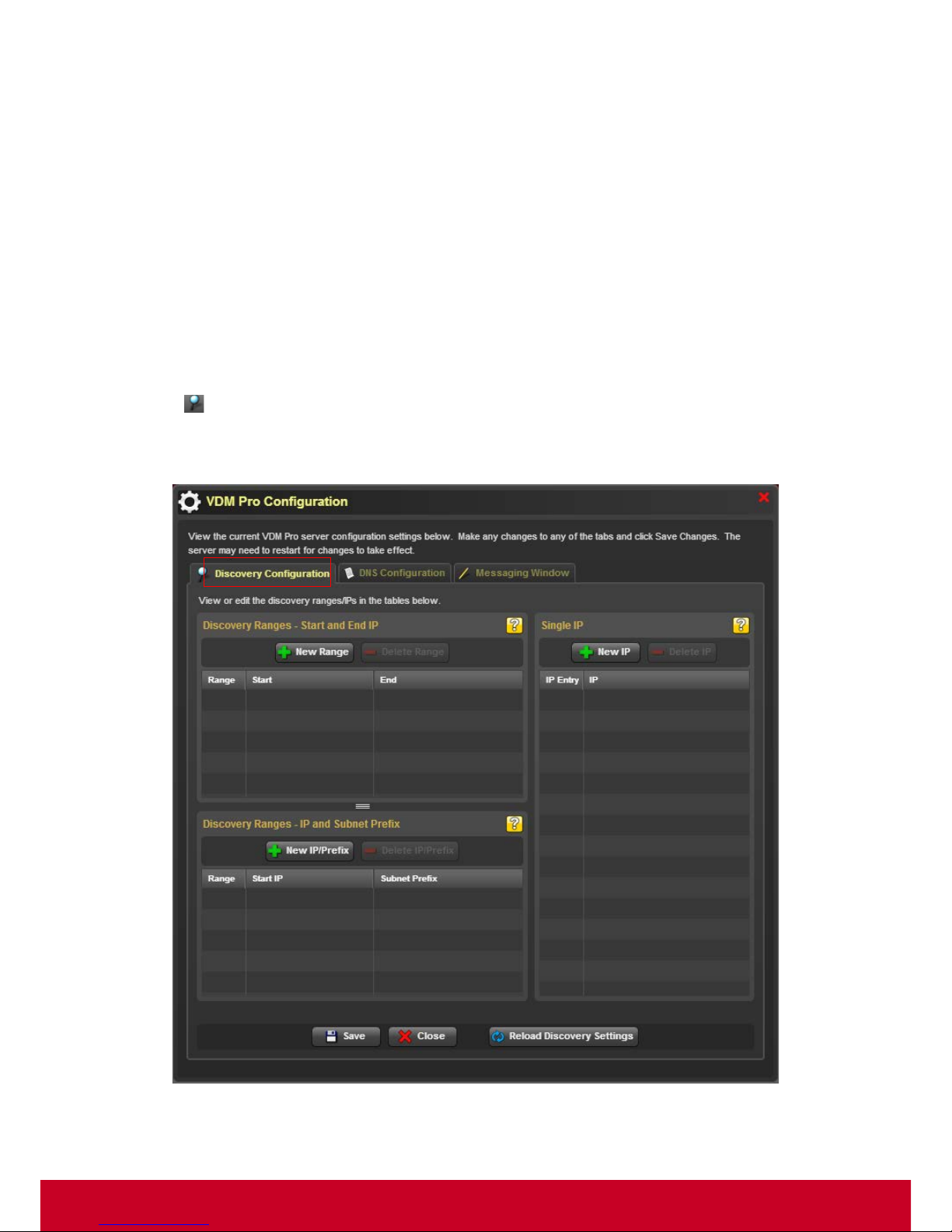
2. Click Open Discovery Settings button in the bottom left-hand side of the Welco me page to
configure the discovery ranges. (Or) Click V DM Pro Options > Configuration > Discovery
Configuration. Discovery Configuration tab is selected by default in VDM Pro Configuration
screen as shown in the screenshot below.
Figure 15: Discovery Configuration
Page 24
23
To Create/Delete Discovery Ranges by Start and End IP:
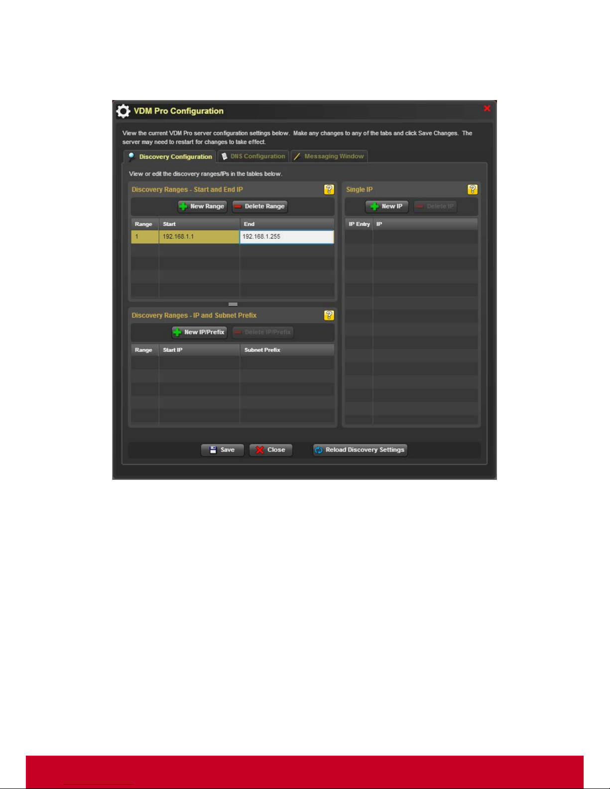
1. Click New Range button to create a new blank entry for providing the IP ranges as shown in the
following screenshot.
Figure 16: Discovery Ranges – Start and End IP
2. Enter the IP address ranges in Start and End columns to discover the devices within the specified
range to avoid unwanted device discovery.
3. Click Save to trigger the discovery process. A Confirmation message appears, click Yes to save
the discovery settings successfully or click No to return to the previous screen.
4. Click Reload Discovery Settings, a Confirmation message appears. Click Yes to reload all the
settings to the saved values or click No to return to the previous screen.
Page 25
24
5. Select a required discovery range and click Delete Range button to delete a discovery range.
Click Save to commit all changes. Entries are limited to 256 addresses.
To Create/Delete a Single IP:
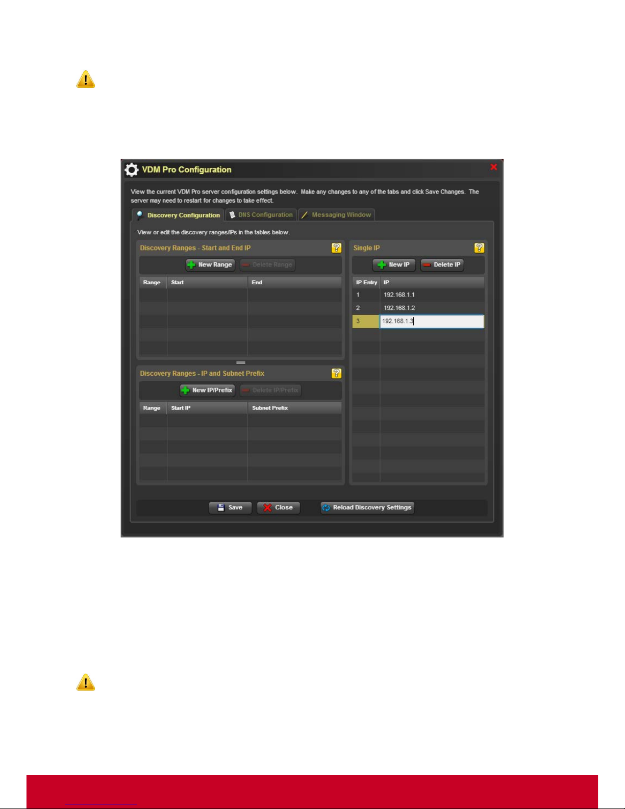
1. Click New IP button to create a new blank entry as shown in the screenshot below.
Figure 17: Create New IP
2. Enter the IP address in the IP field.
3. Click Save to trigger the discovery process. A Confirmation message appears, click Yes to save
the discovery settings successfully or click No to return to the previous screen.
4. Click Reload Discovery Settings, a Confirmation message appears. Click Yes to reload all the
settings to the saved values or click No to return to the previous screen.
5. Select a required IP address and click Delete IP button to delete an IP address.
Click Save to commit all changes. The single IP addresses may have also been added manually
or created with the Add Device function.
Page 26
25
To Create/Delete Discovery Ranges by IP and Subnet Prefix:
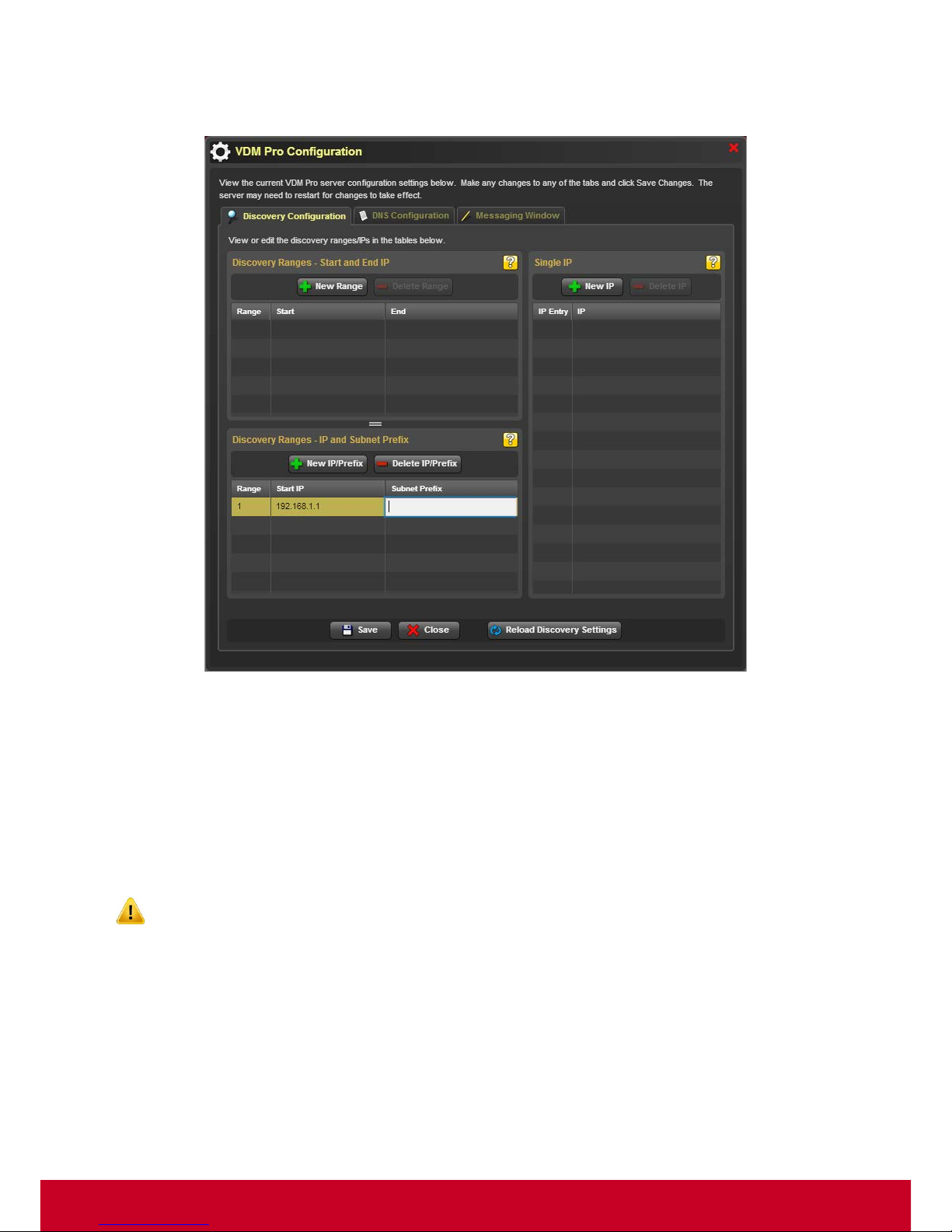
1. Click New IP/Prefix button to create a new blank entry as shown in the screenshot below.
Figure 18: Create New IP/Prefix
2. Enter the starting IP address and Subnet Prefix in the Start IP and Subnet Prefix fields,
respectively.
3. Click Save to trigger the discovery process. A Confirmation message appears, click Yes to save
the discovery settings successfully or click No to return to the previous screen.
4. Click Reload Discovery Settings, a Confirmation message appears. Click Yes to reload all the
settings to the saved values or click No to return to the previous screen.
5. Select a required entry and click Delete IP /Prefix button to delete a discovery range.
Click Save to commit all changes.
The discovered devices in the device tree are una uthenticated devices. To authenticate these devices,
the user has to select the required unauthenticated devices and provide the corresponding user
credentials to identify the devices as SCX Device.
Page 27

26
Messaging Window
Messaging Window provides information for various activities performed by the VDM Pro application.
Whenever the user performs some activities like system login, system logout, device discovery and so
on, a message will be displayed with the timestamp in the Messaging Window. The user can also
configure the output window and optimize the messaging window size according to their needs.
1. Click VDM Pro Options > Configuration > Messaging Window to configure the messaging
window as shown in the screenshot below.
Figure 19: Messaging Window
2. Choose the size of the messaging window from the Messaging Window Size on Startup section.
3. Click Save button to save the settings for messaging window successfully.
Page 28
27
SSL Upload
SSL means Secure Socket Layer, which is a protocol used to ensure secure transactions between
web servers and browsers. The protocol uses a third party, a Certificate Authority (CA) to identify one
end or both end of the transactions. SSL encrypt the segments of network connections at the
Application Layer to ensure secure end-to-end transit at the Transport Layer. SSL certificate is
needed for secured communications over the networks.
VDM Pro supports only .cert and .key files to be part of SSL configuration. Other formats have not
been tested.
To upload SSL certificate:
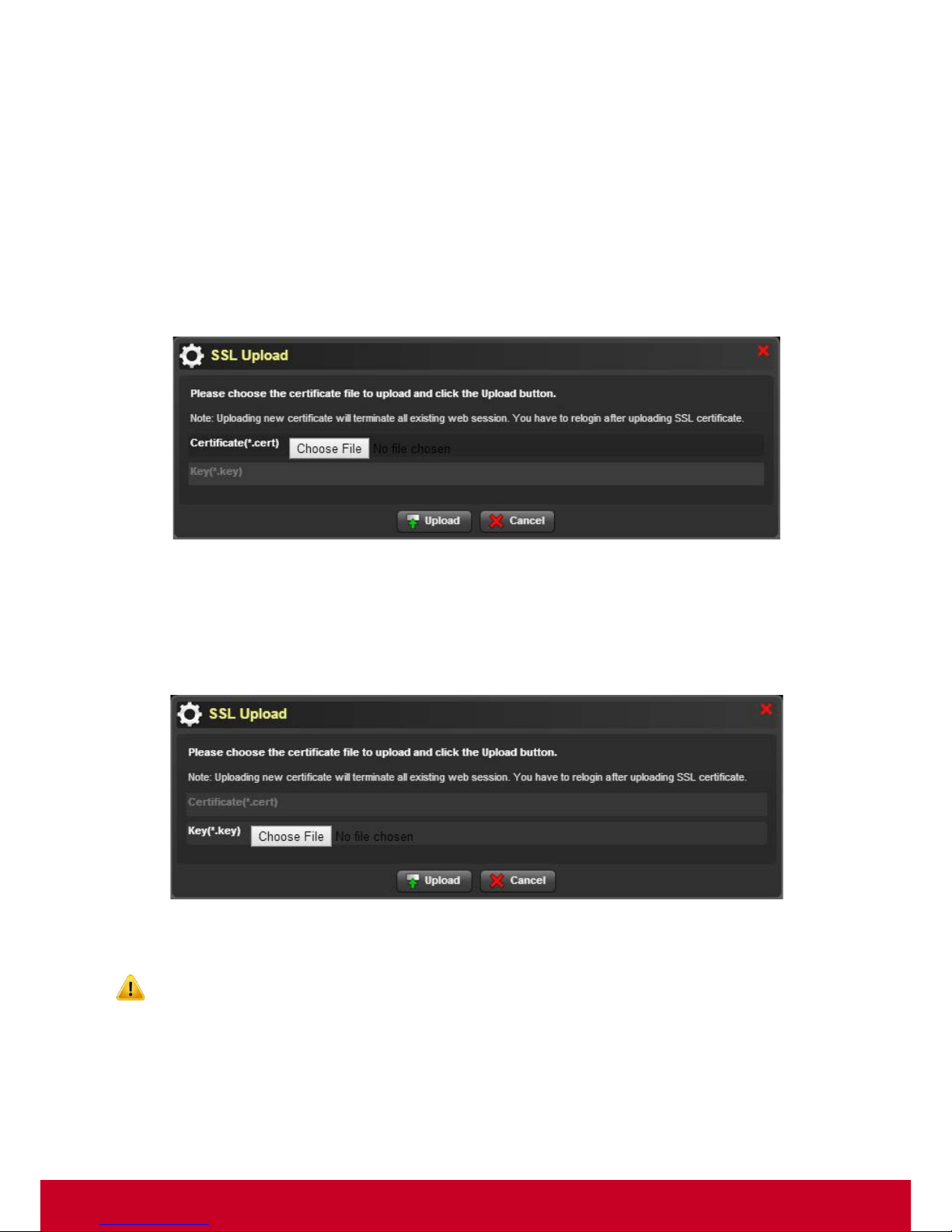
1. Click VDM Pro Options > SSL to upload the SSL certificate file as show n in the screenshot below .
Figure 20: Certificate Upload
2. Click Browse to select the SSL certificate file.
3. Click Upload to upload the SSL certificate file.
4. Once the SSL certificate file is uploaded, Key text box is enabled. Click Browse to select the SSL
key. A related screenshot is displayed below.
Figure 21: Key Upload
5. Click Upload to upload the SSL key.
Uploading new certificate will terminate all existing web sessions. You have to login again after
uploading SSL certificate.
Page 29
28
VDM Pro Users
VDM Pro provides an option to the user for configuring and managing the users on a domain. User
configuration includes
• Configuring User
To configure the user account, the user has to log into the application by providing the user
credentials, the user can login and authenticate the credentials from anywhere in the network. This
helps the administrators to manage many numbers of users on a domain.
Configuring User
VDM Pro provides an option to create their own credentials for logging the VDM Pro application apart
from logging with default username and password. After configuring the user, the user can log into the
application with the newly created user credentials.
Various actions performed on VDM Pro user configuration are as follows:
• Add New User
• Edit User
• Delete User
To add new user:
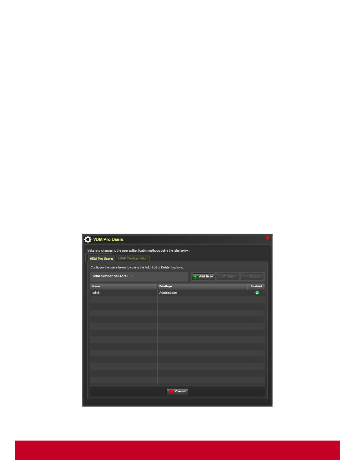
1. Click VDM Pro Options > VDM Pro Users > VDM Pro Users to configure the user as shown in
the screenshot below.
Figure 22: VDM Pro User Configuration
Page 30
29
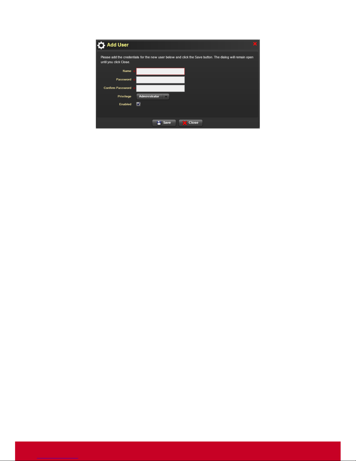
2. Click Add New button to add the credentials as shown in the screenshot below.
Figure 23: Add User
3. Enter the name of the user in Name text box.
4. Enter the user password in Password text box.
5. Enter the same user password in Confirm Password text box as in Password text box.
6. Select the privilege rights to be Administrator or User or Operator or KVM from the Privilege
drop-down box.
7. Check the Enabled checkbox to identify the status of the user. If checkbox is not checked, it will
give a message “The user has been disabled” while logging the VDM Pro application.
8. Click Save to save the new credentials successfully.
To edit user:
1. Click VDM Pro Options > VDM Pro Users > VDM Pro Users to edit the user credentials to avoid
unwanted users from accessing the account.
2. Select the required user and click Edit butto n. An Edit User window is displayed. By default,
Name text box is disabled.
3. Enter user password in Password and Confirm Password text boxes.
4. Select the privilege rights to be Administrator or User or Operator or KVM from the Privilege
drop-down box.
5. Check the Enabled checkbox to identify the status of the user. If checkbox is not checked, it will
throw a message “The user has been disabled” while logging the VDM Pro application.
6. Click Save to save the user credential changes successfully.
To delete user:
1. Click VDM Pro Options > VDM Pro Users> VDM Pro Users to delete any one of the required
user.
2. Select the required user and click Delete button to delete the selected user successfully.
Page 31
30
Configuring LDAP
LDAP is Lightweight Directory Access Protocol, which is an emerging industry standard protocol for
accessing directory servers. LDAP server can authenticate the users as it supports authentication.
Using LDAP in a local network, the user can configure LDAP Server information, where the data is
transferred on a secured layer and authenticate the users from anywhere on the network.
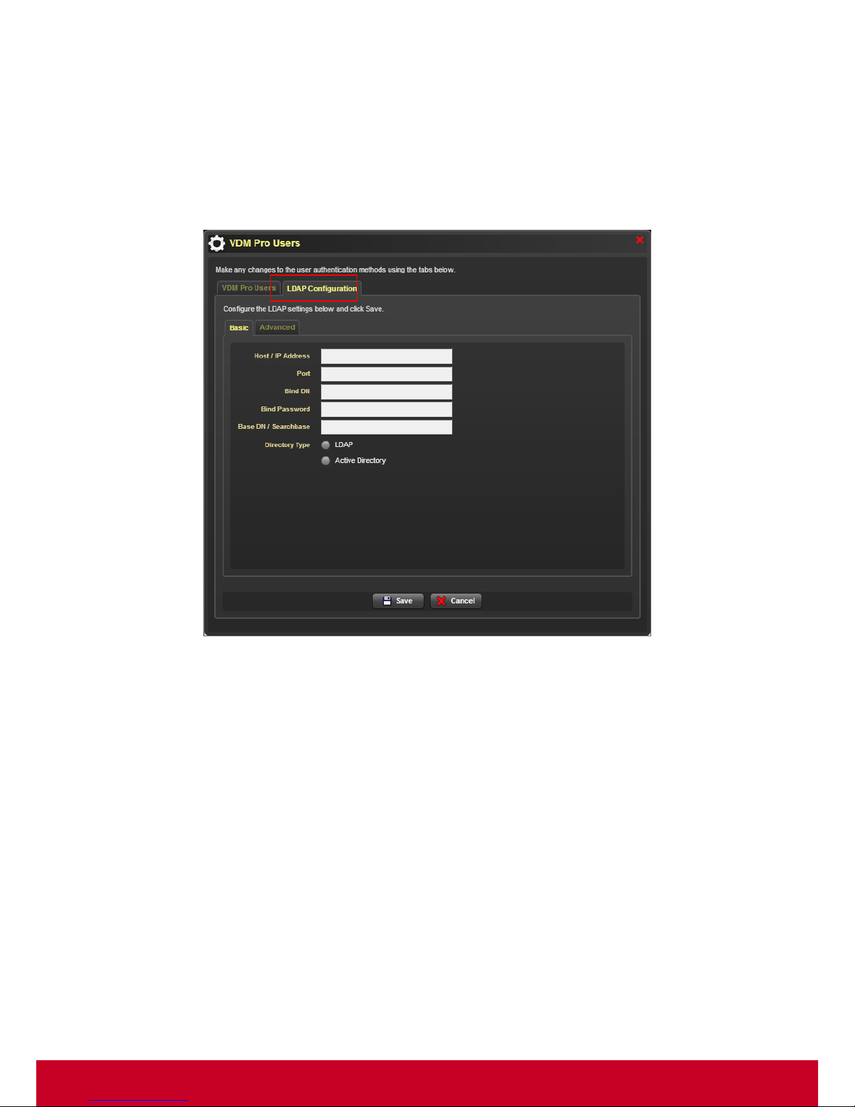
1. Click VDM Pro Options > VDM Pro Users > LDAP Configuration to configure LDAP setti ngs as
displayed in the subsequent screenshot.
Figure 24: Basic LDAP Configuration
2. Enter the name of the host or IP address in the Host/IP Address t ext box. This could be the IP
address of the LDAP server.
3. Enter the port address in the Port text box. Default port is 389.
4. Enter the domain name in the Bind DN text box.
5. Enter the password in the Bind Password text box.
6. Enter the base domain name under which the user accounts are located in the Base
DN/Searchbase text box. This option is required for most account related operations.
Page 32
31
7. Select the type of directory to be either LDAP or Active Directory based on the LDAP server
configuration on your network.
If LDAP directory type is selected, Bind Requires DN checkbox under Advanced settings will be
enabled (or) if Active Directory is selected, Bind Requires DN checkbox under Advanced
settings will be disabled.
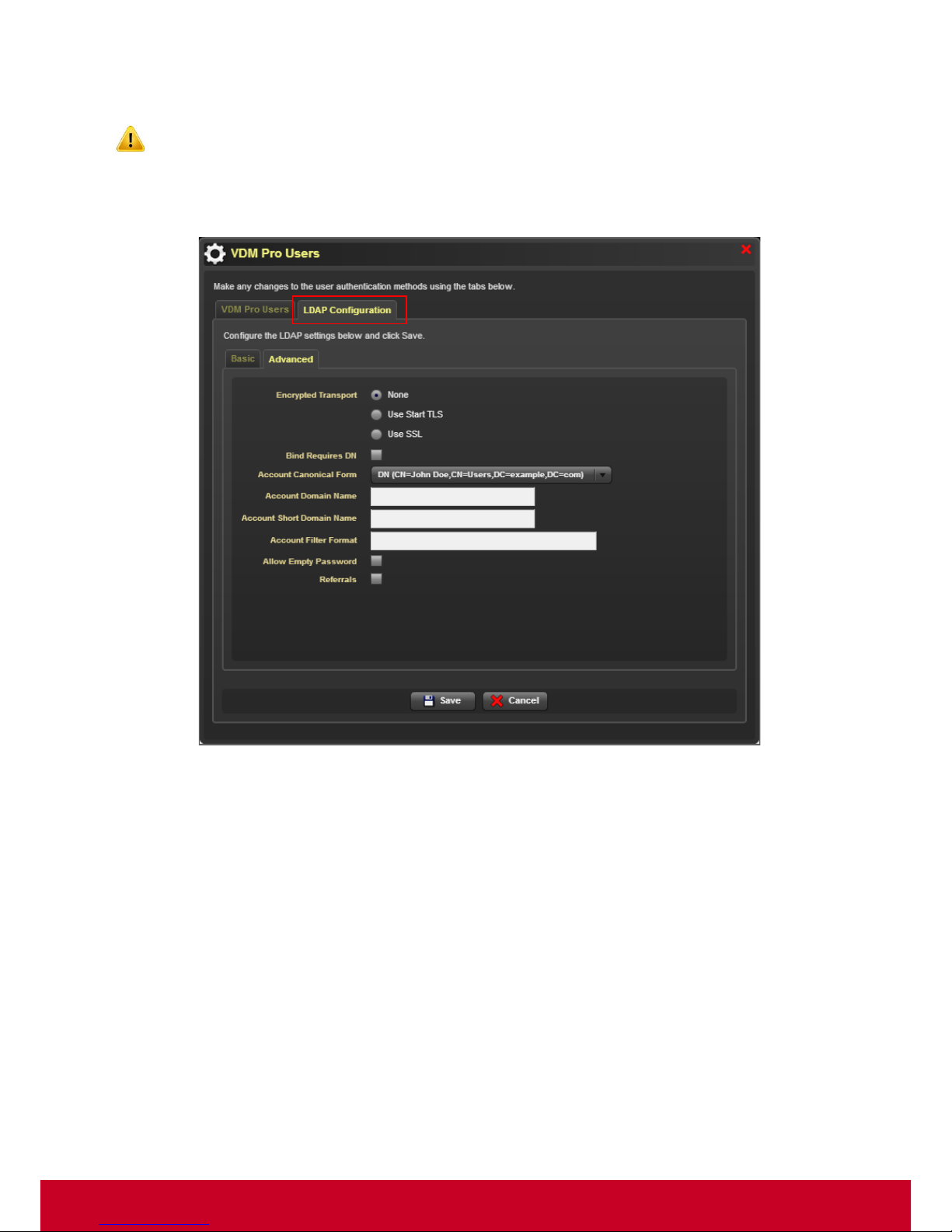
8. Click Advanced tab to configure LDAP settings as shown in the screenshot below.
Figure 25: Adva nced LDAP Configuration
9. Select None or Use Start TLS or Use SSL from the Encrypted Transport button.
10. Check the Bind Requires DN checkbox to retrieve the domain name for the account used to bind
if the username is not already in DN form.
11. Select an account format that indicates the form to which the account names are canonicalized
from the Account Canonical Form drop-down list.
12. Enter the name of the account domain in the Account Domain Name text box.
13. Enter the short name of account domain in Acco unt Short D omain Name text box.
14. Enter the filter format to search for the accounts in the Account Filter Format text box.
15. Check the Allow Empty P assword checkbox to allow empty password during bind.
16. Check the Referrals checkbox to allow referrals.
17. Click Save to save the LDAP configuration successfully.
Page 33
32
Language Selection
VDM Pro supports localization for the list of languages. The GUI will take the local browser’s language
by default. VDM Pro provides an option to change the language settings according to the needs of the
user.
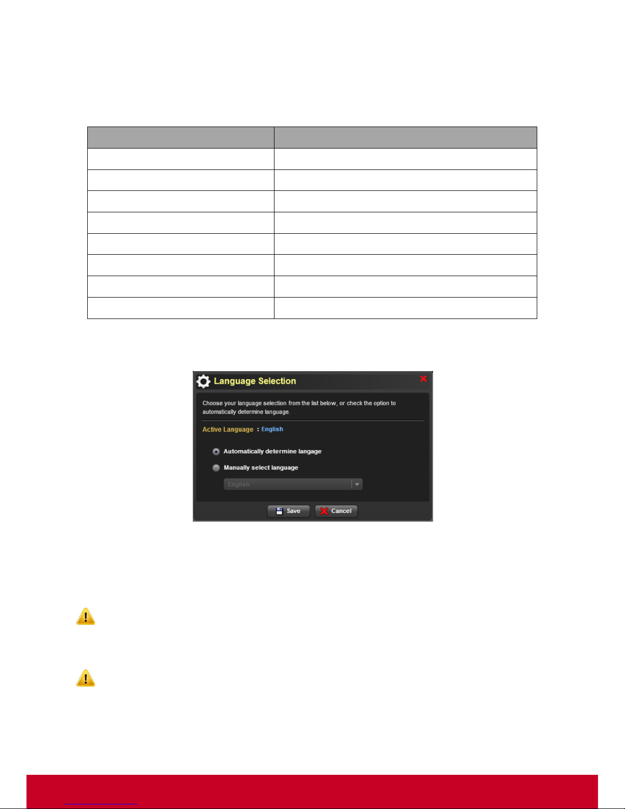
1. Click VDM Pro Options > Language, a Language selection w indow is displayed as show n in the
screenshot below.
Figure 26: Language Selection
2. Choose either Automatically determine language button to determine the language as English
(default language) automatically or Manually select language button to choose the language
type manually from the drop-down list. Depending upon the language selection, the language
name will be displayed in the Active Language.
While selecting Automatically determine language button, manually select language
drop-down list will be disabled.
3. Click Save to save the language settings successfully.
VDM Pro needs to be reloaded for the language selection to take effect.
Language
Language code
English
EN-US
Traditional Chinese
ZH-TW
Simplified Chinese
ZH-CN
French
FR
Korean
KR
Spanish
SP
Portuguese
PT
Russian
RU
Page 34
33
Chapter 7
VDM Pro Tools
VDM Pro Reports Framework
Report Manager is a framework that allows users to create various type of reports based on the data
available in the back end database. The reports include from simple computer information to a
complex system statistics in a graph. Reports can be generated either in tabular data or in graphical
format. It is a very useful tool provided as a part of VDM Pro, which provides data information for the
user.
Report Manager provides a rich set of feature that allows the user to configure and export the report
results to the report file. The report file supports various formats like HTML, XML, PDF and
spreadsheet (CSV). The reports generated using Report Manager is independent of plug-ins. There
are two types of reports. They are as follows.
• System Report - Generates pre-defined reports for the selected plug-ins. In addition, the user can
select multiple reports and multiple result formats for g enerating the reports. At least one result
format must be selected for generating the reports.
• User Report - Generates user-defined reports for the selected plug-ins. In addition, the user can
select multiple reports and multiple result formats for g enerating the reports. At least one result
format must be selected for generating the reports.
Following are the System Report features:
System Report
Feature
Description
Edit Report
Allows the user to edit the required system report and save as user
report.
• Click Report List tab from the VDM Pro Report Manager page.
• Select System Report from the Report Type drop-down list.
• Select the required plug-ins from the Extensions drop-down list.
• Select the required system reports from the Selection field
column.
• Select the required format for the selected system report.
• Click Save as button, Edit Report
page appears. Make
necessary changes in the field’s text boxes.
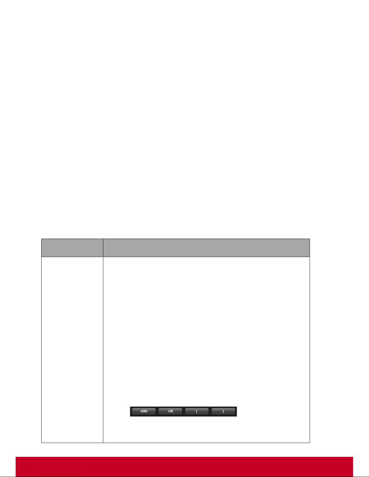
• Click Advance Filter button, Filter Settings window is displayed.
Select the operator fr om the drop-down list and enter the value
in the text box for the required fields.
• Click Add command button to display the values for the selected
fields in the text box and click the required operator buttons
(
) to filter the selected
fields.
• Click Clear to clear the data in the text box.
Page 35
34
• Click OK button to set the filter for the selected fields.
• Select the required field from the Add fields, and click to
include in the Selected fields
. If needed, the user can exclude
the required fields from the Selected fields by clicking .
• Click Save to user report t
o save the report as User Report
successfully.
Generate Report
Allows the user to generate the required system reports in the desired
formats.
• Click Report List tab from the VDM Pro Report Manager page.
• Select System Report from the Report Type drop-down list.
• Select the required plug-ins from the Extensions drop-down list.
• Select the required system reports from the Selection field
column.
• Select the required format for the selected system report.
• Click Generate button, Device Selection window appears.
Select the required tab and select the required device from the
Selection field column.
• Click OK
to generate the reports. The generated reports are
viewed in Generated Report tab or click List > Result List.
• Select the required result from the Selection
field column and
click Preview to view the generated reports in the browser or clic k
Download button to download the report in a particular location.
Delete
Generated
Report
Allows the user to delete the generated reports.
Select the required report from the Selection
field column under
Generated Report tab and click Delete
to delete the selected system
reports successfully.
Schedule Report
Allows the user to schedule a selected system report from the list of
reports.
• Click Report List tab from the VDM Pro Report Manager page.
• Select System Report from the Report Type drop-down list.
• Select the required plug-ins from the Extensions drop-down list.
• Select the required system reports from the Selection field
column.
• Select the required format for the selected system report.
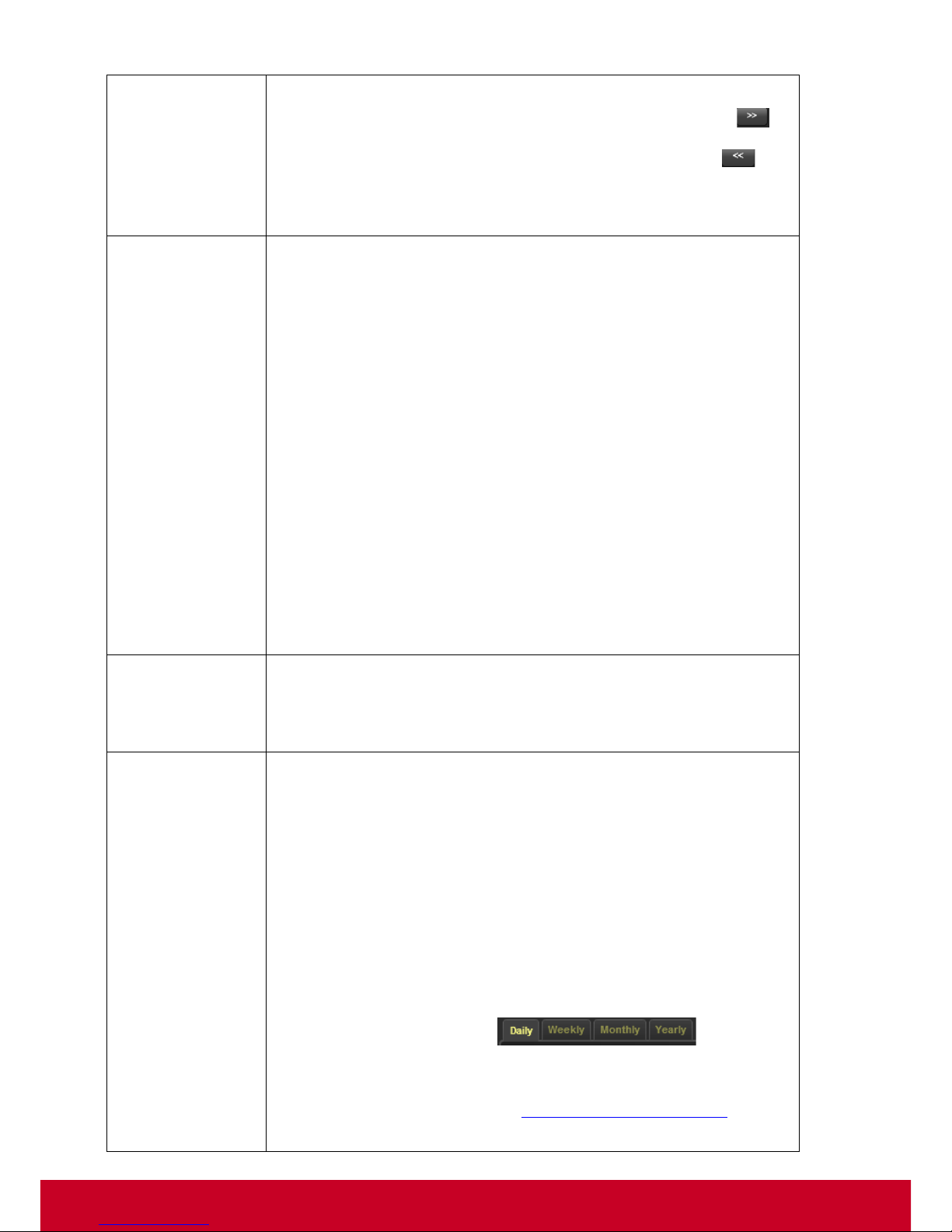
• Click Schedule > New Schedule, Schedule Report
page is
displayed. Make necessary changes in the field’s text boxes and
click the required tabs ( ) to schedule
a report on daily or weekly or monthly or yearly basis.
• Click Set, a Choose Email Destinations… window is displayed.
For more information, see “Choose Email Destinations...”.
• Choose the required Email from Add f ield column and click OK.
Page 36

35
An Email address will be automatically populated in the Email
text box.
• Click Next button, Device Selection window appears. Select the
required device from the Selection field column.
• Click OK
to schedule the reports. The scheduled reports are
viewed under Scheduler tab or click Schedule > Schedule List.
Edit Scheduled
Report
Allows the user to make necessary changes in the scheduled system
reports.
• Click Scheduler tab from the VDM Pro Report Manager page.
• Select the required scheduled report from the Selection field
column and click Edit. An Edit Schedule
page is displayed.
Make necessary changes and click Next button. A Device
Selection
window appears. Select the required device from the
Selection field column.
• Click OK to save the changes successfull
y, and viewed under
Scheduler tab or click Schedule > Schedule List.
Delete
Scheduled
Report
Allows the user to delete the unwanted scheduled system reports.
• Select the required schedule report from the Selection field
column under Scheduler tab.
• Click Delete to delete the selected scheduled reports
successfully.
Page 37
36
Following are the User Report features:
User Report Feature
Description
Add Report
Allows the user to add a new user report.
• Click Report List tab from the VDM Pro Report Manager page.
• Select User Report from the Report Type drop-down list.
• Click Add button, New Report page is displayed.
• Provide necessary details in the field’s text boxes and select the
required plug-ins from the Extension drop-down list.
• Click Advance Filter button, Filter Settings window is display ed.
Make necessary filter settings for the fields.
• Click OK button to set the filter for the selected fields.
• Select the required field from the Add fields button, and click
to include in the Selected fields
. If needed, the user can
exclude the required fields from the Selected fields by clicking
.
• Click Next to add a report successfully.
Edit Report
Allows the user to make necessary changes in the required user reports.
• Click Report List tab from the VDM Pro Report Manager page.
• Select User Report from the Report Type drop-down list.
• Select the required plug-ins from the Extensions drop-down list.
• Select the required user reports from the Selection field column.
• Click Edit button, Edit Report page is displ
ayed. Make
necessary changes in the fields.
• Click Ad vance Filter
button to make the necessary changes in
the filter settings.
• Include or exclude the required fields by clicking and .
• Click Save to save the changes successfully.
Delete Report
Allows the user to delete the unwanted user reports.
• Click Report List tab from the VDM Pro Report Manager page.
• Select User Report from the Report Type drop-down list.
• Select the required plug-ins from the Extensions drop-down list.
• Select the required user reports from the Selection field column.
• Click Delete button, a Confirmation message appears. Click Yes
to delete the selected user reports successfully.
Generate Report
Allows the user to generate the required user reports in the desired
formats.
Page 38
37
• Click Report List tab from the VDM Pro Report Manager page.
• Select User Report from the Report Type drop-down list.
• Select the required plug-ins from the Extensions drop-down list.
• Select the required user reports from the Selection field column.
• Click Generate button, Device Selection
window appears.
Select the required tab and select the required devices from the
Selection field column.
• Click OK
to generate the reports. The generated reports are
viewed in Results tab or click List > Result List.
• Select the required user report from the Selection
field column
and click Preview to view the generated reports in the browser or
click Download
button to download the report in a particular
location.
Schedule Report
Allows the user to schedule the required user reports.
• Click Report List tab from the VDM Pro Report Manager page.
• Select User Report from the Report Type drop-down list.
• Select the required plug-ins from the Extensions drop-down list.
• Select the required user reports from the Selection field column.
• Click Schedule > New Schedule, Schedule Report
page is
displayed. Make necessary changes in the field’s text boxes and
click the required tabs ( ) to schedule
a report on daily or weekly or monthly or yearly basis.
• Click Next button, Device Selection window appears. Select the
required device from the Selection field column.
• Click OK
to schedule the user reports. The scheduled user
reports are viewed under Scheduler tab or click
Schedule >
Schedule List.
Edit Scheduled
Report
Allows the user to make necessary changes for the scheduled user
reports.
• Click Scheduler tab from the VDM Pro Report Manager page.
• Select the required scheduled report from the Selection field
column and click Edit. An Edit Schedule
page is displayed.
Make necessary changes and click Next button. A Device
Selection
window appears. Select the required device from the
Selection field column.
• Click OK
to save the changes successfully, and viewed under
Scheduler tab or click Schedule > Schedule List.
Delete
Scheduled
Report
Allows the user to delete the unwanted scheduled user reports.
• Select the required schedule report from the Selection field
column under Scheduler tab and click Delete
to delete the
selected scheduled reports successfully.
Page 39
38
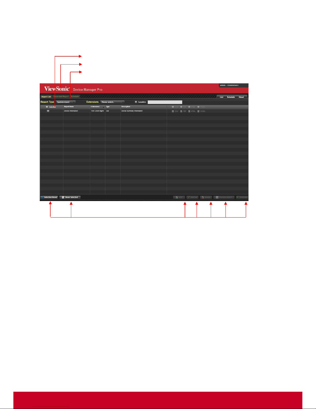
Click VDM Pro Tools > Launch Report Manager to launch report manager from VDM Pro as shown
in the subsequent screenshot.
Figure 27: Report Manager
List of Reports
Top Banner
Menu Bar
Actions
Page 40
39
Retrieving VDM Pro S e rver Even ts
An event is any significant occurrence in the system or in a program that requires the users to be
notified or an entry is added to a log. Therefore, event logs help the user to identify and diagnose the
source of current system problems, predict potential system problems and records the activities
performed by the VDM Pro Server.
VDM Pro has its own event logging mechanism that helps end user to identify the problems on the
managed devices. VDM Pro does not log any events from the managed devices in this section.
List of possible events are available in the Appendix: Event Logs
.
To retrieve VDM Pro server events:
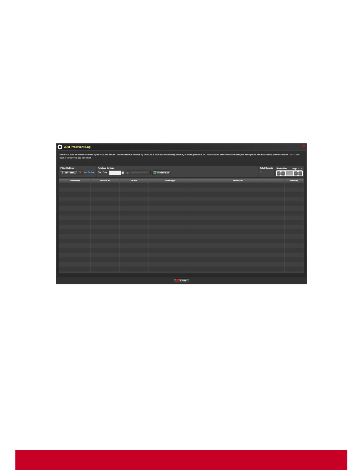
1. Click VDM Pro Tools > VDM Pro Event Log, an VDM Pro Server Events window is displayed as
shown in the following screenshot.
Figure 28: VDM Pro Server Events
Page 41
40
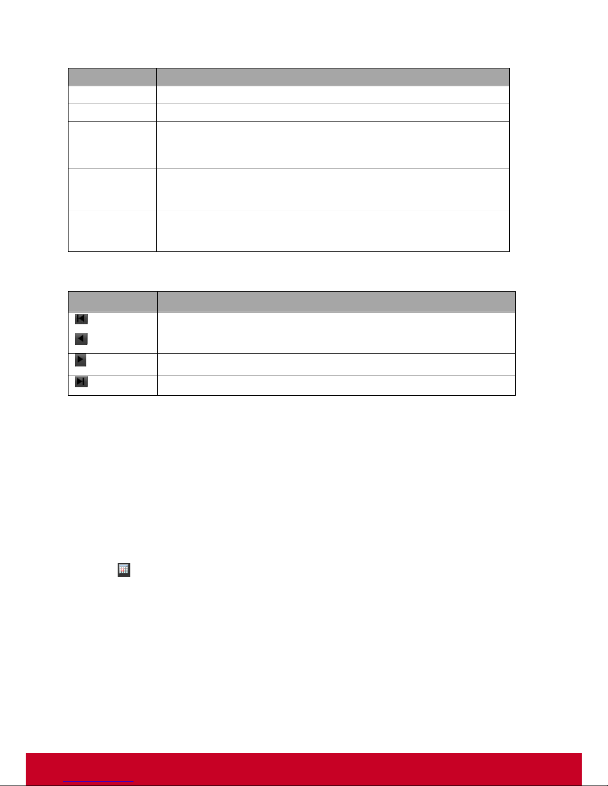
Field Description
Fields
Description
Timestamp
Time at which the event is generated.
Node or IP
Represents the node or IP associated with the event.
Component
and Event
Type
Represents the major component that logged the event, such as, Base,
HX, CX and DX.
Represents the type of event that is logged in.
Event Data
Represents any extra data associated with an event. This may include
any additional text information that is specific to the ev ent, such as a use r
name.
Severity
Measures the impact of the defect on the overall operation of the events.
They are Unknown, Good / Normal, Warning, Critical, Non Recoverable
and Information.
Pagination Description
Icon
Description
Moves to the first page.
Moves to the previous page.
Moves to the next page.
Moves to the last page.
2. Click Set Filter… button, a Set Filter Options… window is displayed to set the filtering option for
the event components.
a. Select All or required component to filter from the Component drop-down list. If the
component is selected, then the fields under Event Source and Cause will be enabled.
b. Select All or required reason and cause from Primary Reason, Secondary Reason and
Generic Cause drop-down lists.
c. Select All or required severity for the event source from the Severity drop-down list.
d. Click Set Filter to set the filter for the selected event source or click Clear Filter to clear the
set filter.
3. Click to select start date and click Retrieve by Date to retrieve a record date wise.
4. Click Retrieve All to retrieve all the records and the count is displayed in Total Records.
Page 42

41
Downloading VDM Pro Logs
In VDM Pro, the user can download the logs that contain Access log, Error log and VDM Pro log.
VDM Pro Logs
This VDM Pro core log file keeps track of VDM Pro core processing like database access, command
execution, etc.
Access Log
This is an access log for httpd server, which records all the requests processed by the httpd server.
The information’s stored in the access log can be used to analyze for producing useful statistics.
Error Log
This is an error log for httpd server, which is the most important log file and is the place, where
Apache httpd will send diagnostic information and record any errors that encounter in processing the
requests. It is the first place to look, w hen a problem occurs with the operation of the server or starting
the server, because it contains details of what went wrong and how t o fix it. The format of an error log
is relatively free form and descriptive. However, there is certain information that is contained in most
of the error log entries. For example, here is a typical message.
[Fri Jan 22 10:43:02 2010] [notice] Parent: Created child process 2424
A wide variety of different messages can appear in the error log. Error log entries dealing with
particular requests have corresponding entries in the access log.
1. Click VDM Pro Tools > Download VDM Pro Logs, a window is displayed to download the logs.
2. Select a required location to download the logs and click Save to complete the download
operation successfully.
Page 43
42
Messaging Ac tions
VDM Pro allows the user to perform the following messaging actions:
• Restart Messaging
• Stop Messaging
Restart Messaging
Restart Messaging action restarts the messaging system in the message console. During this action,
the system will be reset that is clear the fault status and reset the timestamp retrieval to zero.
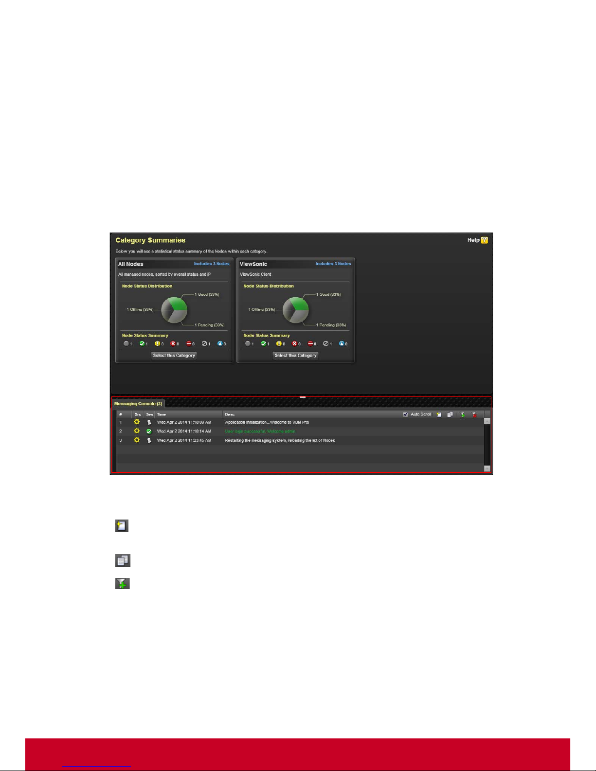
1. Click VDM Pro Tools > Restart Messaging as shown in the screenshot below.
Figure 29: Restart Messaging
2. Check the Auto Scroll checkbox to scroll the messages displayed in the message console.
3. Click Clear Console Entries button to clear the message entries displayed in the message
console.
4. Click Copy to clipboard button to copy the entries to clipboard.
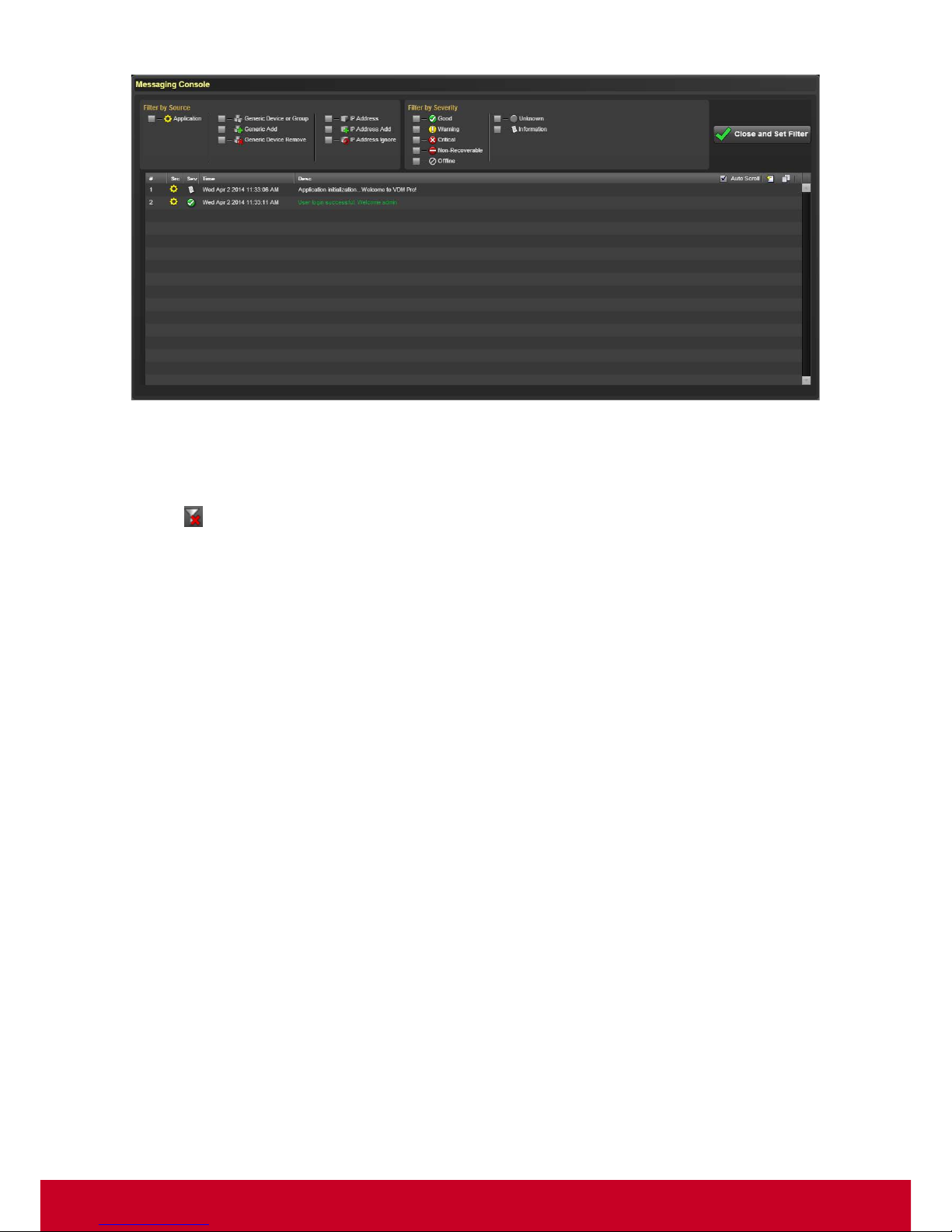
5. Click Add/Edit Filter button to add or edit filters. This opens a M essaging C onsole wi ndow as
shown in the screenshot.
Page 44
43
Figure 30: Messaging Console - Add/Edit Filter
6. Select the required filters from the grids Filt er by Source and Filter by Severity.
7. Click Close and Set Filter to save the selected filters and return to the previous page.
8. Click Clear Filter button to clear the filters to de fault.
Stop Messaging
Stop Messaging action stops displaying the numerous real time updates like adding new devices to
the list, removing ignored devices, health status and connectivity status of the device and so on in the
message console. To stop displaying the messages in the message console, click VDM Pro Too ls >
Stop Messaging.
Page 45
44
Chapter 8
Device List Operation
In VDM Pro, various operations are performed on the device list. The device list includes the
following:
• Node Management Groups - includes management devices
• IP Management Groups - includes list of discovered IPs
• Device Options - includes tooltip and button labels for the devices
• Messaging Console Options - includes the options to control messaging console
• Category Summaries – includes the statistical summary of the Nodes within each category.
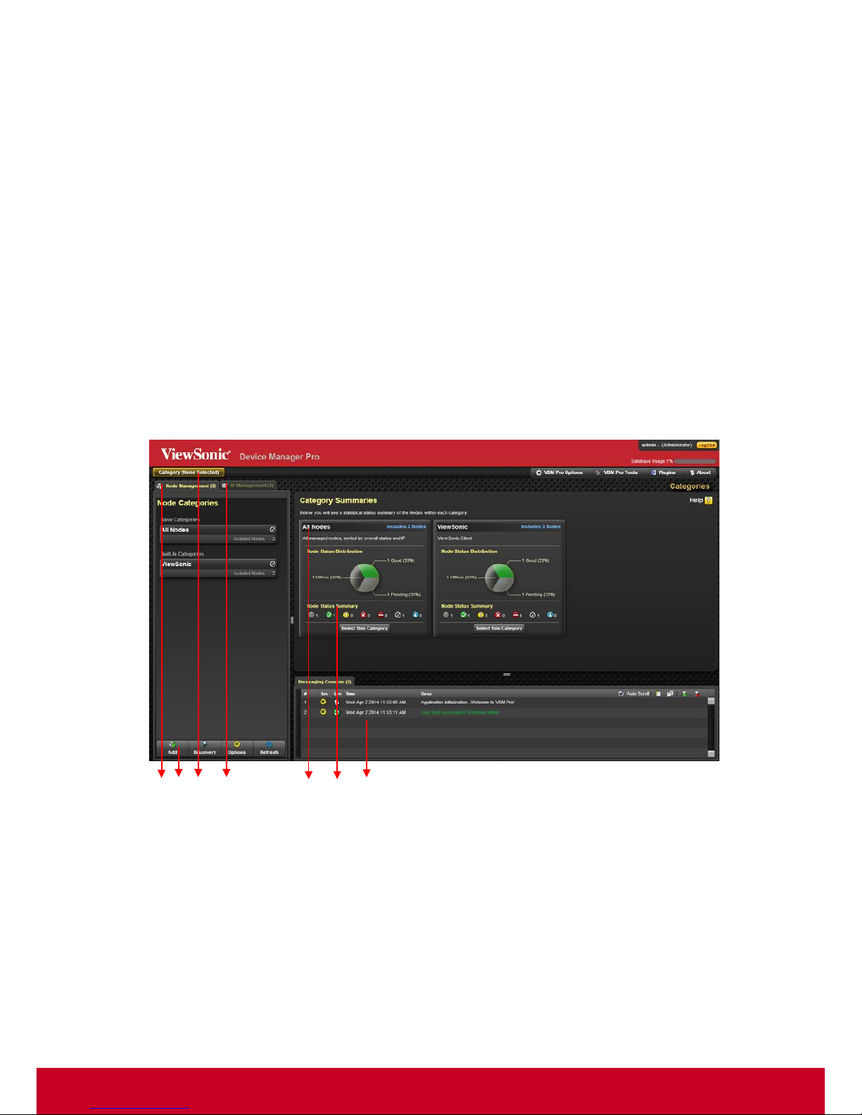
A sample screenshot is shown below.
Figure 31: Device List Layout
A. Node Management Group, B. Device Options, C. Navigation Pane, D. IP Management Group, E.
Node Distribution Status, F. Category Summary, G. Messaging Console Group
A
B C D
E
F
G
Page 46
45
Node Management Group
Node Management Group consists of Smart Client Management devices.
On clicking any one of the managed devices in the Node Management Group, a list of node
manageable devices appears.
To manage a device, select a manageable device. This opens Node Manageability page. For more
information on how to manage a selected device type, refer VDM Pro SCX.
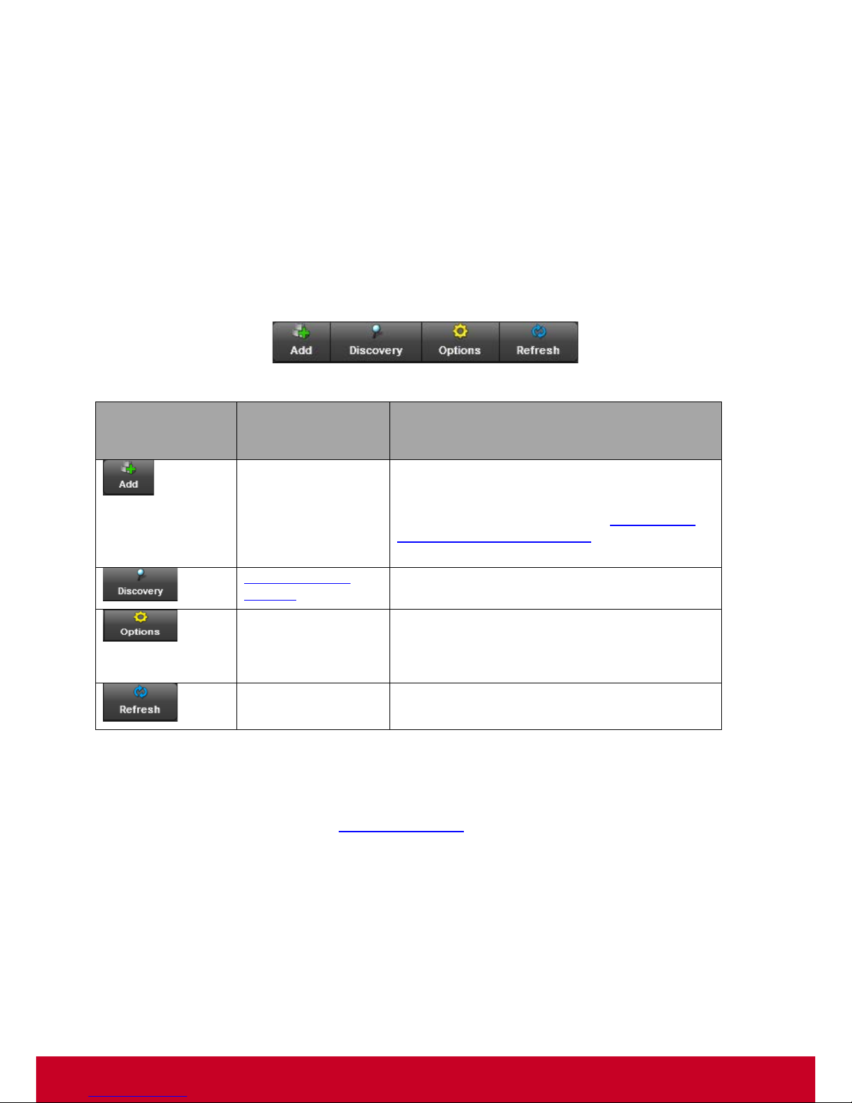
Device Options
The user can perform the following device options:
Figure 32: Device Options
Command
Bar
Buttons
Pop-up
Menu
Description
Add New Device
Allows you to add node manageability by
selecting either an IP address to scan or from
the list of supported types. To know more
about adding a new device, refer Adding Node
by IP, Device or Manageability under VDM
Pro-Smart Client Management (SCX).
Open Discovery
Settings
Allows you to configure discovery ranges.
List Options
Allows you to enable or disable ,
1. Device summary tooltip
2. Button labels on command bar
Refresh the
Device List
Refreshes and reloads the device list.
Messaging Console Options
Messaging Console allows the user to control messaging actions. For information on how to use the
options in messaging console, refer “Messaging Actions
”.
Page 47
46
Category Summaries
The Category Summaries shows a statistical breakdown of the nodes inside each category, including
the total number of detected nodes, and the health status of the nodes.
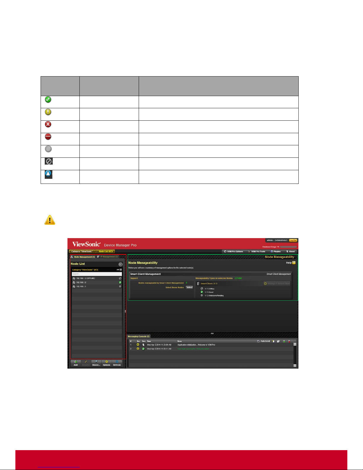
The health status of the device is displayed in the following table.
Health
Icon
Health Status
Description
Good
Device’s overall health status is in good state.
Warning
Device’s overall health status is in warning state.
Critical
Device’s overall health status is in critical state.
Non- Recoverable
Device’s overall health status is in non-recovery state.
Status Pending
Device’s overall health status is in unknown state.
Offline
Device is offline.
Update
Device is undergoing upgrade process.
Click Select this Category from any one of nodes in the Category Summaries window, a Node List
window appears as shown in the screenshot below.
The Node List window is highlighted in red, whereas the Node Manageability window is
highlighted in green.
Figure 33: Node List
From the Node List window, the user can check the health status of the devices. In addition, a tooltip
appears where the user can view the status of the health icon by placing the cursor on an icon.
Page 48
47
IP Management Group
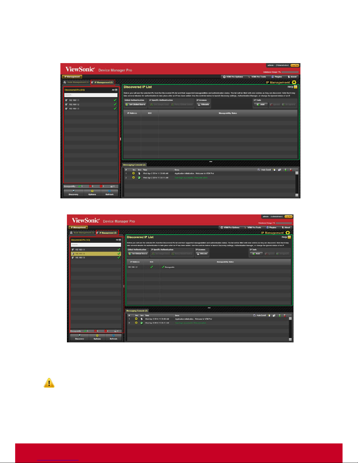
The IP Management group shows all the detected IP addresses and their detected protocols. Click IP
Management grid, a Discovered IP List window appears as shown in the screenshot below.
Figure 34: IP Management
Figure 35: Discovered IP list
The Discovered IP List shows the list of all discovered IPs with their supported manageability and
authentication status. The list will be filled with new entries as they are discovered.
It may take several minutes for authentication to take place after an IP has been added.
Page 49
48
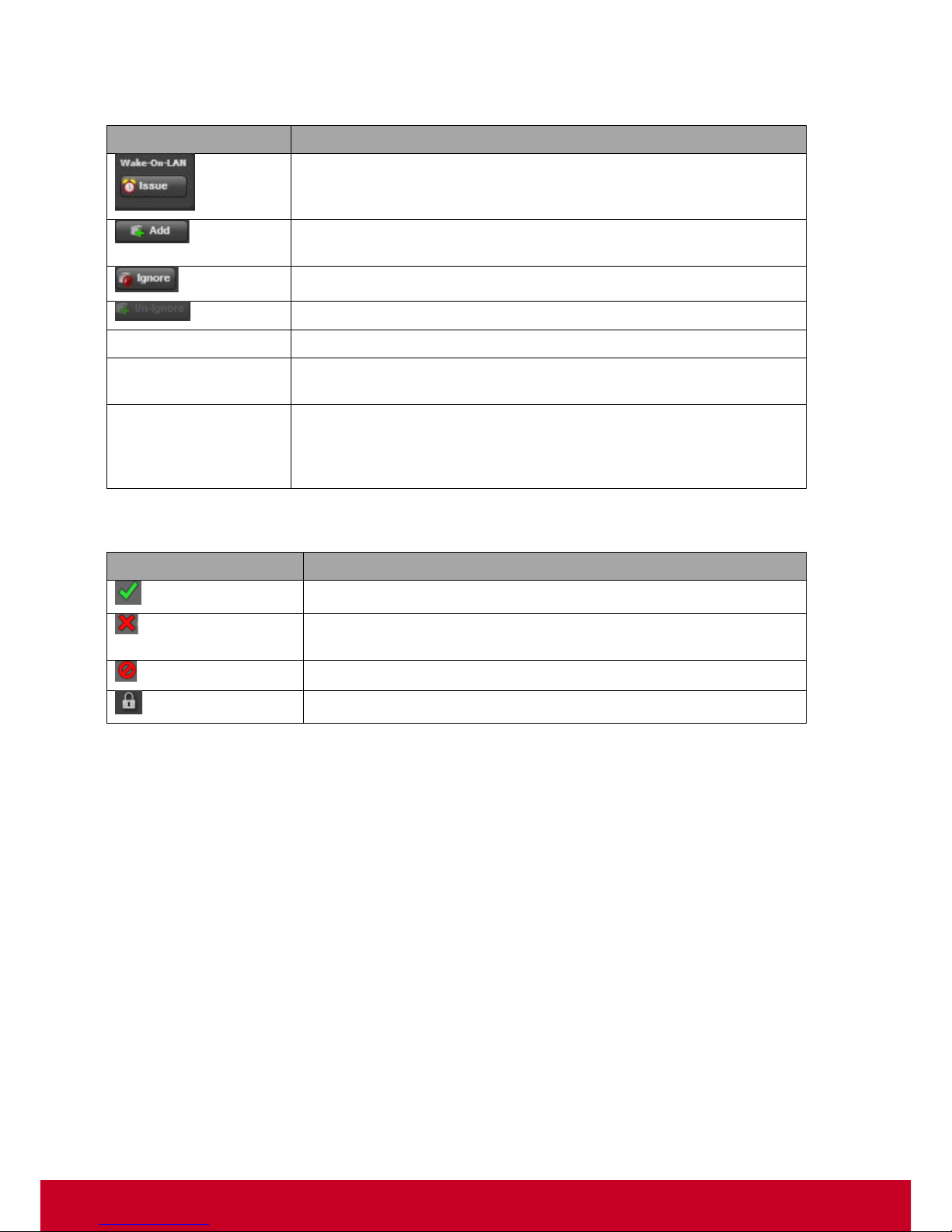
Use the controls below to launch Discovery settings, Authentication Manager, or change the Ignored
status of an IP.
Button Options
Description
Allows the user to dispatch Wake-On-LAN command for the
selected IPs.
Adds an IP address to allow the server to discover the associated
devices.
Allows the user to set ignore state for the selected IPs.
Allows the user to undo the ignore state for the selected IPs.
IP Address
Indicates the list of available IP addresses.
Protocols such as
AMT, Windows OS
Indicates the detected protocols such as AMT, Windows OS, and
Linux OS that are currently installed.
Manageability
Status
Indicates the current manageability status of the IP. For a device to
be considered managed, at least one protocol must authenticate
successfully. If any IPs are ignored, their status will be reflected
here as well.
The manageability status of the detected IPs is displayed on the left-hand bottom side of the page.
Button Options
Description
Indicates the devices that support at least a single manageability.
Indicates the devices that cannot authenticate or support any
protocol.
Indicates the devices that are ignored.
Indicates the devices that are not licensed.
Page 50
49
Chapter 9
About VDM Pro
View VDM Pro Information
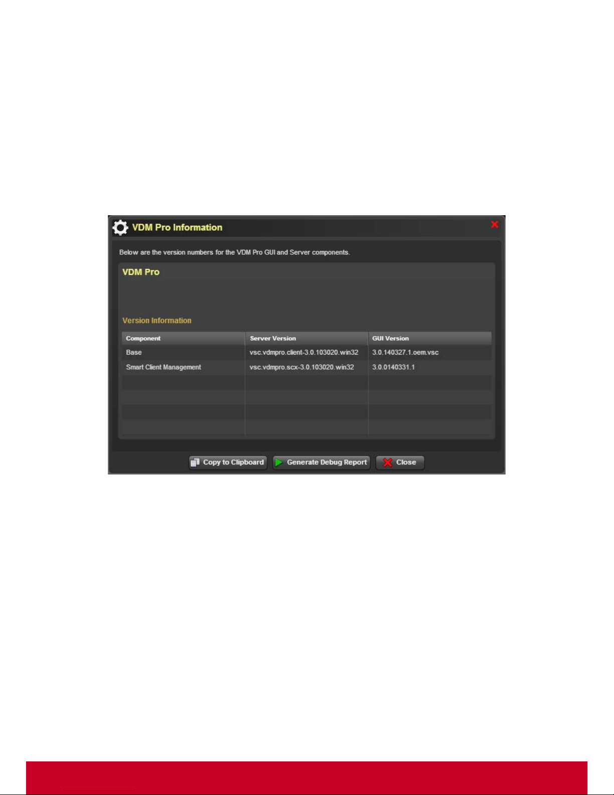
In About VDM Pro, details about the version information of VDM Pro GUI and Server components
are provided.
Click About > VDM Pro Information. A screenshot is shown below.
Figure 36: VDM Pro Information
To copy the information to clipboard, click Copy to Clipboard.
Page 51
50
Generate Debug Report
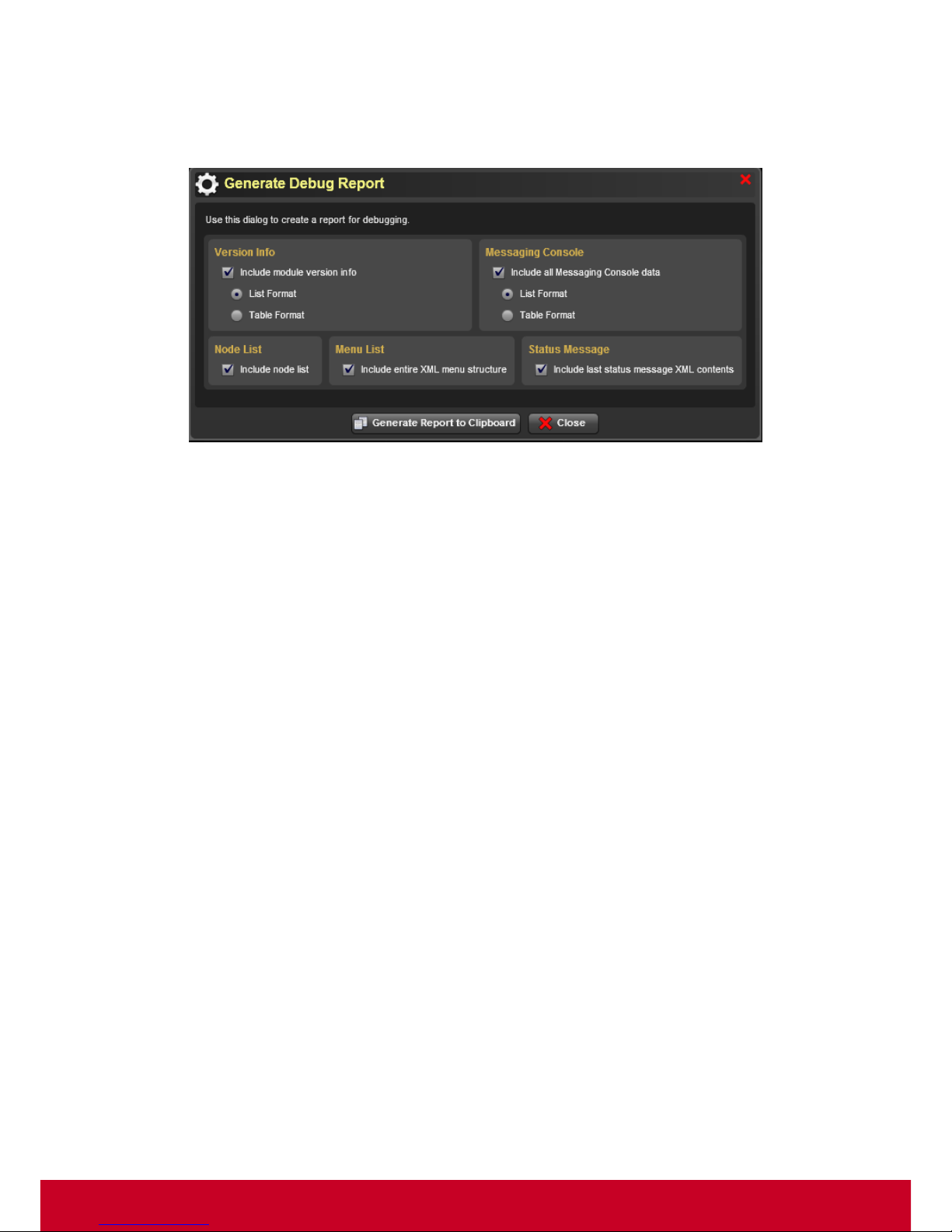
To generate Debug report, click Generate Debug Report. This opens a Generate Debug Report
dialog as shown in the screenshot below.
Figure 37: Generate Debug Report
Select the required options from the dialog and click Generate Report to Clipboard to generate the
debug report to a clipboard.
Page 52

51
Chapter 10
Smart Client Managemen t (S CX)
Introduction
Smart Client Management (SCX) is a thin client management extension for VDM Pro that provides
aggregated management of thin client devices equipped with VDM Pro thin client agents. SCX will
provide remote manageability of the system.
Following are the major features that are provided by SCX, in multiple phases:
• System Information - Provides hardware information of thin client device.
• Quick Connection- Provides basic connection setting for Citrix HDX, Mic rosoft R emoteFX, and
VMware.
• Client Setting – Provides advanced thin client device setting such as, connection, appearance, IP
and keyboard.
• Password Setting- Provides password setting for administrator for the thin client device.
• Power Control - Allows the user to control power of the managed client.
• VNC Connector - KVM Viewer helps the users (mainly IT administrators) to remotely view or
manage a single thin client device.
• Send Message
• Remote FW Update - Users can update Firmware from remote for the selected client systems.
• Group management - Divides devices into various groups for different connection and general
settings.
If the user needs to manage the managed device through SCX, then VDM Pro thin client agent
should be enabled in the managed device.
Hardware Requirement
• Required in Managed Clients for being managed by SCX –
VDM Pro thin client agent should be shipped with the firmware (FW) of the device.
Page 53

52
System Requirement for Installing SCX
Minimum system requirements for the installing SCX are:
• System Processor - 2.0 GHz and above
• System Memory - Minimum 4 GB RAM
• Free Disk Space - 10GB (May need more disk space depending on the nodes managed and the
amount of history information needed)
Supported Operating Systems for Installing SCX
• Windows 2003
• Windows 2008
• Windows Vista
• Windows 7
• Windows 8
Security
SCX provides a secured way to manage the servers and other components in a data center or
enterprise.
• HTTPS is used to secure the web interface
• ViewSonic propriety protocol is used to secure agent interface
• MD5-CHAP will be used for a secured authentication
Compatibility
The web interface of SCX is compatible with the following browsers:
• IE 6.0 and later
• Firefox 2.0 and later
Page 54
53
Chapter 11
Smart Client Management Configuration
Smart Client Management facilitates the user with options for configuring an application for various
features according to the user needs and identifying the attributes of the product to meet the purpose
of an end user. This helps the user to use an application easily and effectively.
Various feature configurations are as follows:
• Adding Single Device
• Managing Groups
• Managing Firmware
• Managing Connection Policies
• Managing Client Policies
• Configuring Connection Settings
• Configuring Client Settings
• Configuring Password Settings
Viewing Smart Client Management Page
To view Smart Client Management page, follow the steps given below:
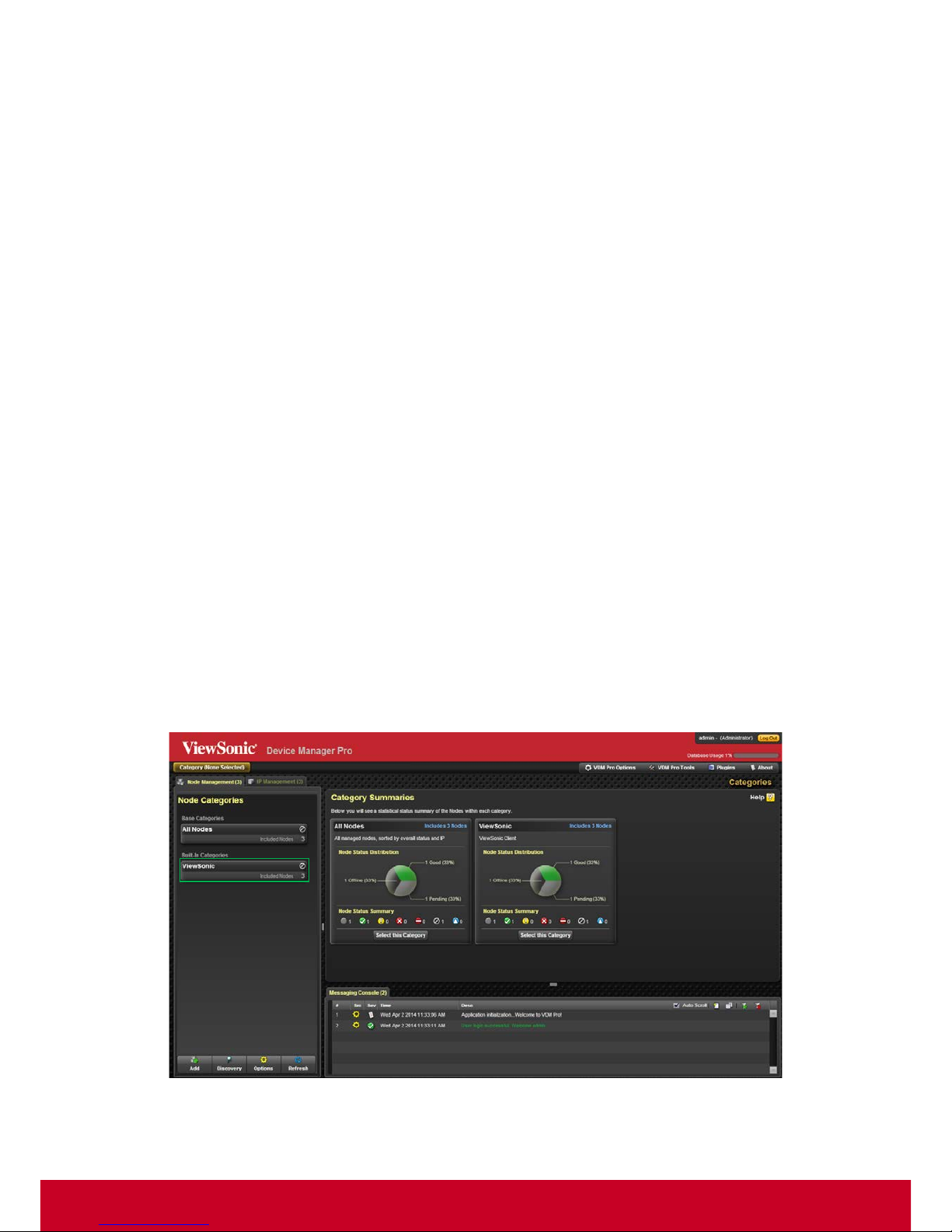
1. After logging into VDM Pr o, click VDM Pro from the left-hand side of the Node Management
page as shown in the subsequent screenshot.
Figure 38: Main - Node Management Page
Page 55
54
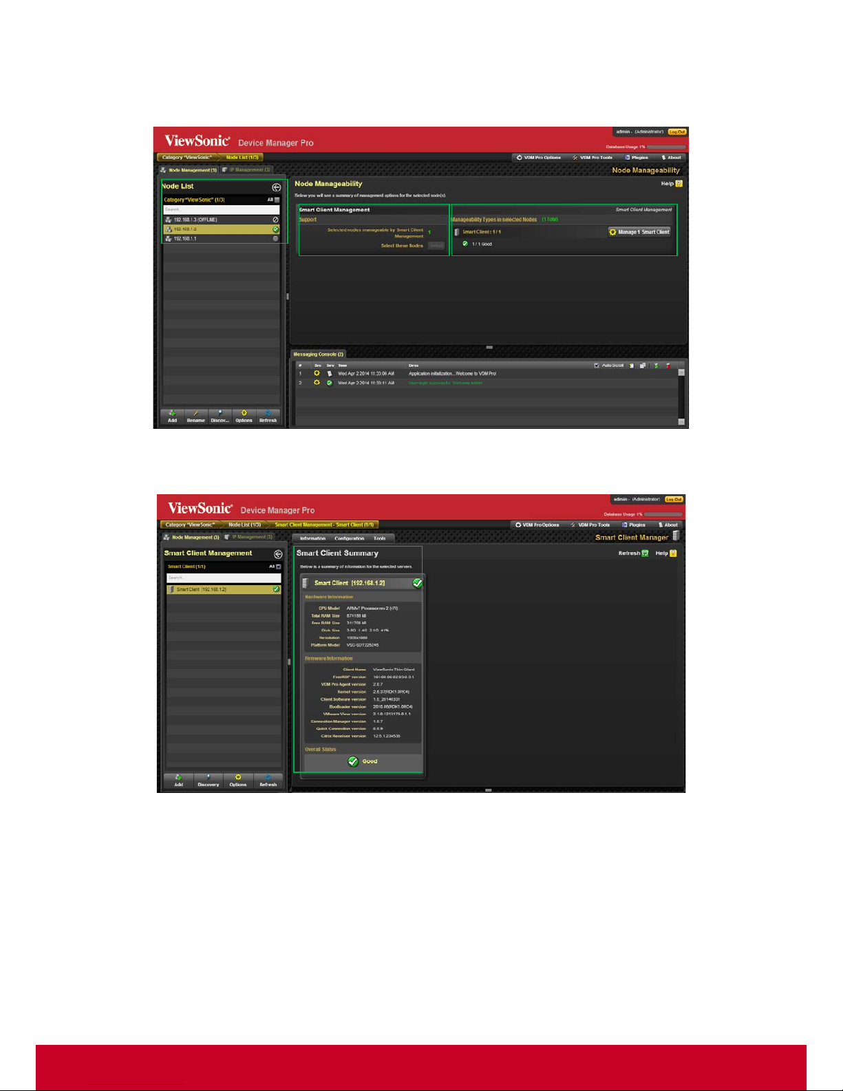
2. This opens a Node Manageability window, as shown in the subsequent screenshot. Select the
required device(s) from the Node List and click Manage Smart Client from the Manageability
Types in selected Nodes grid.
Figure 39: Node Manageability
3. This opens Smart Client device window, as shown in the screenshot below.
Figure 40: Smart Client Management Page
Page 56
55
Group Management
SCX allows the user to divide devices into various groups for different connections and general
settings. The user can create a new group, edit an existing group, or delete a group. Follow the steps
given below to manage groups.
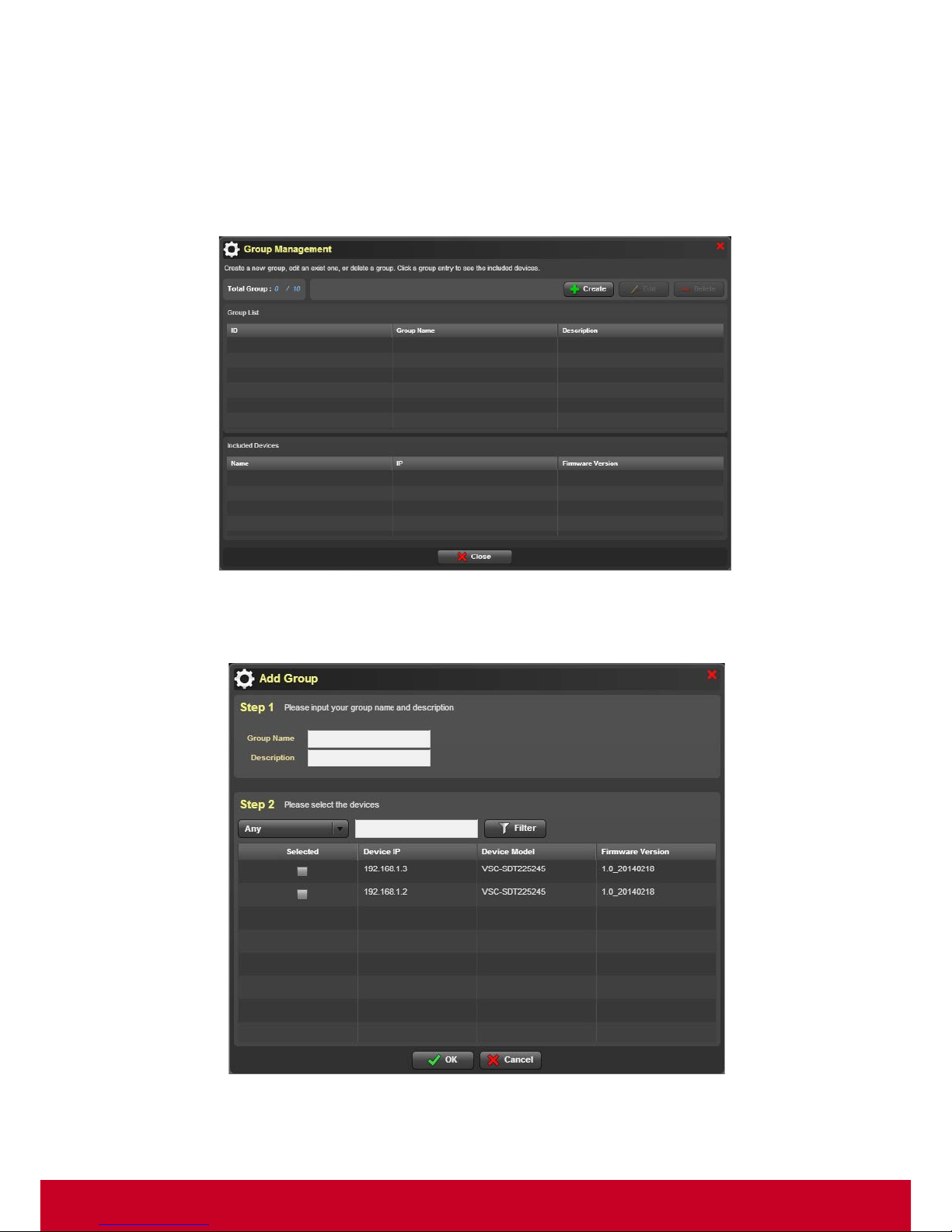
1. Click Plugins > Smart Client Management > Group Management. A Group Management dialog is
displayed as shown in the subsequent screenshot.
Figure 41: Group Management
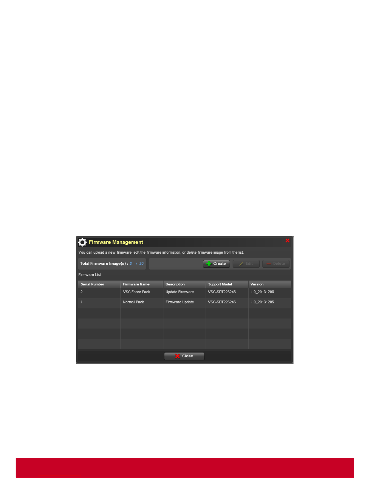
2. Click Create to add a group. This opens an Add Group dialog as shown in the subsequent
screenshot.
Figure 42: Add Group
3. In Add Group dialog, under Step 1, enter the group name and description in the Group Name
and Description text fields, respectively.
Page 57
56
4. In Step 2, select the required devices from the device list.
5. Select the type of device that needs to be listed from Any option Enter the device details in search
bar and click Filter.
6. Click OK to save the entered details.
7. In the Group Management Page, the included devices will be displayed in the Included Devices
list.
8. In the device list and click Edit to edit a selected group. An Add Group dialog is displayed as
shown in the above screenshot.
9. Follow the steps mentioned above in order to edit a group.
10. In the Group Management Page, select a required group and click Delete to delete a group.
Firmware Manager
Administrators have a need to update Firmware in a thin client that they manage, when a new
Firmware is available. Doing this operation on all mana ged systems w ithout any automation or remote
capabilities is a difficult task. SCX simplifies this by providing options to remotely update Firmware of
multiple client systems. SCX allows the user to upload a new firmware and manage firmware.
Follow the steps given below to manage Firmware.
Uploading Firmware
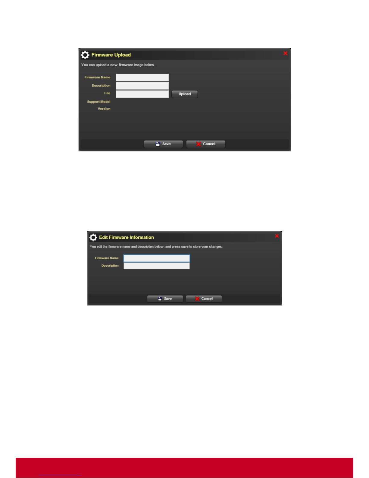
1. Click Plugins > Smart Client Management > Firmware Manager > Firmware Upload. A Firmware
Management dialog is displayed as shown in the subsequent screen.
Figure 43: Firmware Management
Page 58
57
2. Click Create to create a new firmware. A Firmware Upload dialog is displayed as shown in the
subsequent screenshot.
Figure 44: Firmware Upload
3. Enter the firmware descriptions in the Firmware Na me and Description text fields.
4. Click Upload to select a firmware from the local machine and upload a firmware.
5. Click Save to upload a firmware successfully.
6. In the Firmware Management dialog, select a required firmware and click Edit to edit a selected
firmware’s details. An Edit Firmware Information dialog is displayed as shown in the subsequent
screenshot.
Figure 45: Edit Firmware Information
7. Enter the required firmware details in the Firmware Name and Description text fields.
8. Click Save to save the entered details.
9. In the Firmware Management dialog, select a required firmware and click Delete to delete a
firmware.
Page 59
58
Deploying Firmware
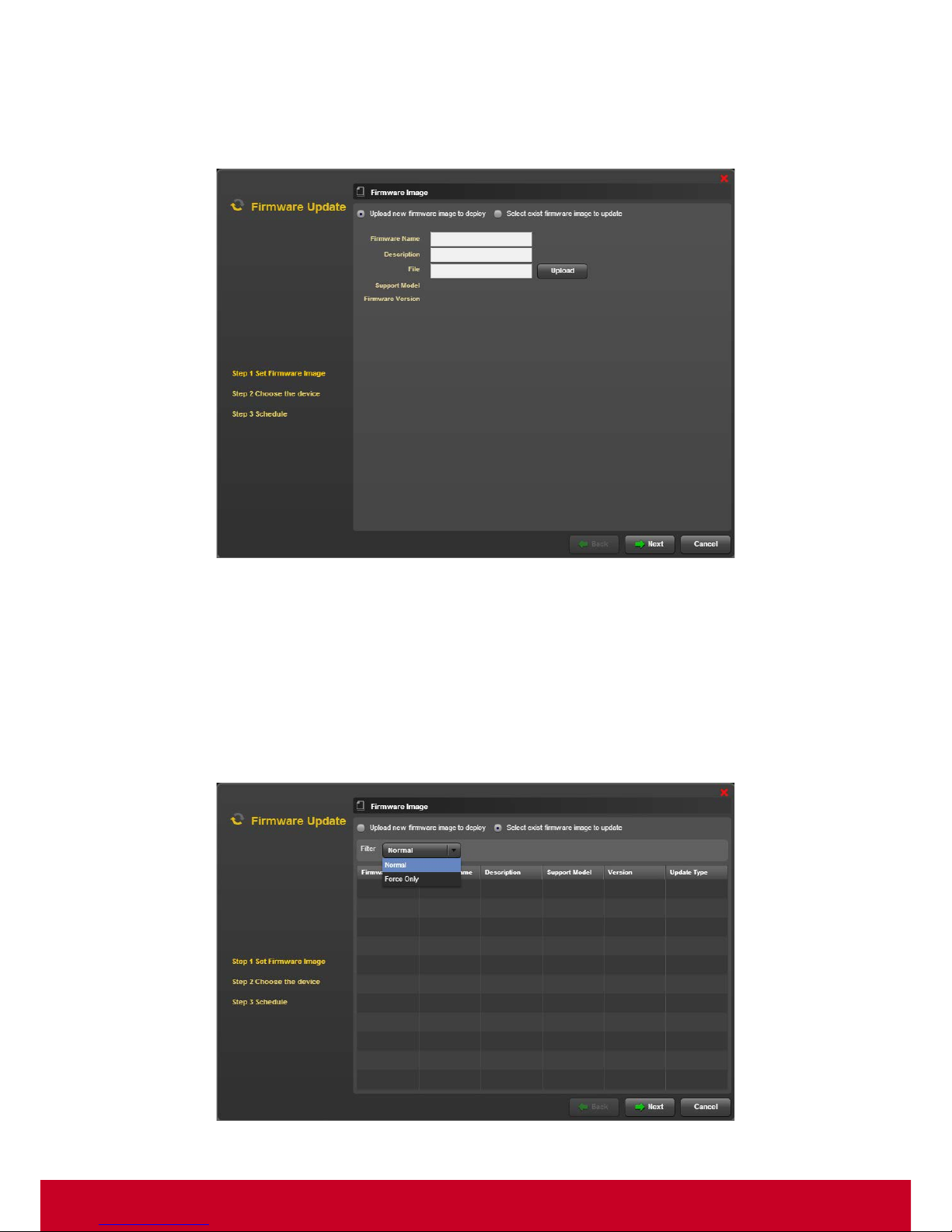
1. Click Plugins > Smart Client Management > Firmware Manager > Firmware Update. A Firmware
Update dialog is displayed as shown in the subsequent screen.
Figure 46: Firmware Updat e
2. In the Firmware Update dialog, select Upload new firmware image to display option.
3. Enter the firmware descriptions in Fi rmware Na me and Description text fields.
4. Select Upload in order to select and upload a new firmware image.
5. Choose Select exist firmware image to update. This action enables the Step 1 Set Firmware
Image options as shown in the subsequent screenshot. When you select “Normal”, all the “normal
packages” will be shown on the list; when you select “Force Only”, only “force packages” will be
presented.
Figure 47: Firmware Update - Set Firmware Image
Page 60
59
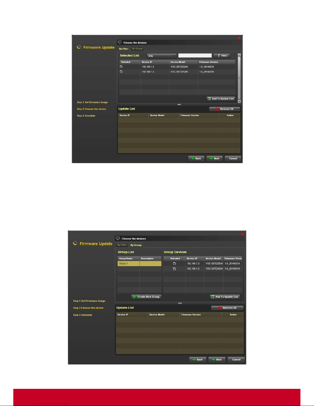
6. Click Next to move to the Choose the device step as shown in the subsequent screenshot.
Figure 48: Firmware Update - Choose the devices
7. In the Choose the device step, click By Filter tab. Select the required devices and click Add to
Update List. The selected devices will be added to Update List.
8. Click the select devices from the Update List and click Remove All to remove the selected
devices from the Update List.
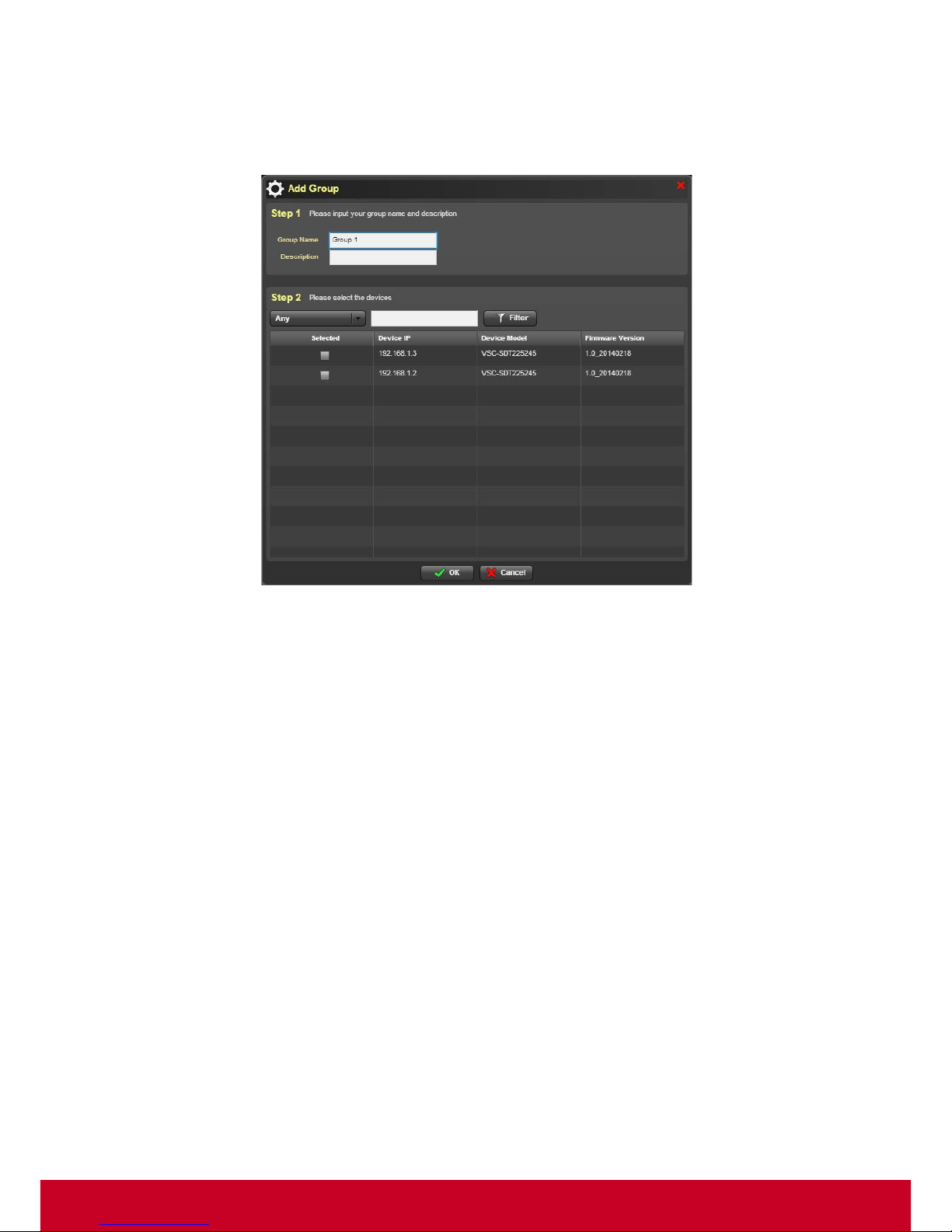
9. In the Choose the device step, click By Group tab as shown in the subsequent screenshot.
Figure 49: Choose the devices - By Group
Page 61
60
10. Select the required group name from the Group List and select the required group devices. Click
Add to Update List in order to add the selected devices to the Update List.
11. In order to create a group, click Create New group. Click Create to add a group. This opens an
Add Group dialog as shown in the subsequent screenshot.
Figure 50: Add Group
12. In Add Group dialog, under Step 1, enter the group name and description in the Group Name
and Description text fields, respectively.
13. In Step 2, select the required devices from the device list.
14. Select the type of device that needs to be l isted from Any option Enter the device details in search
bar and click Filter.
15. Click OK to save the entered details.
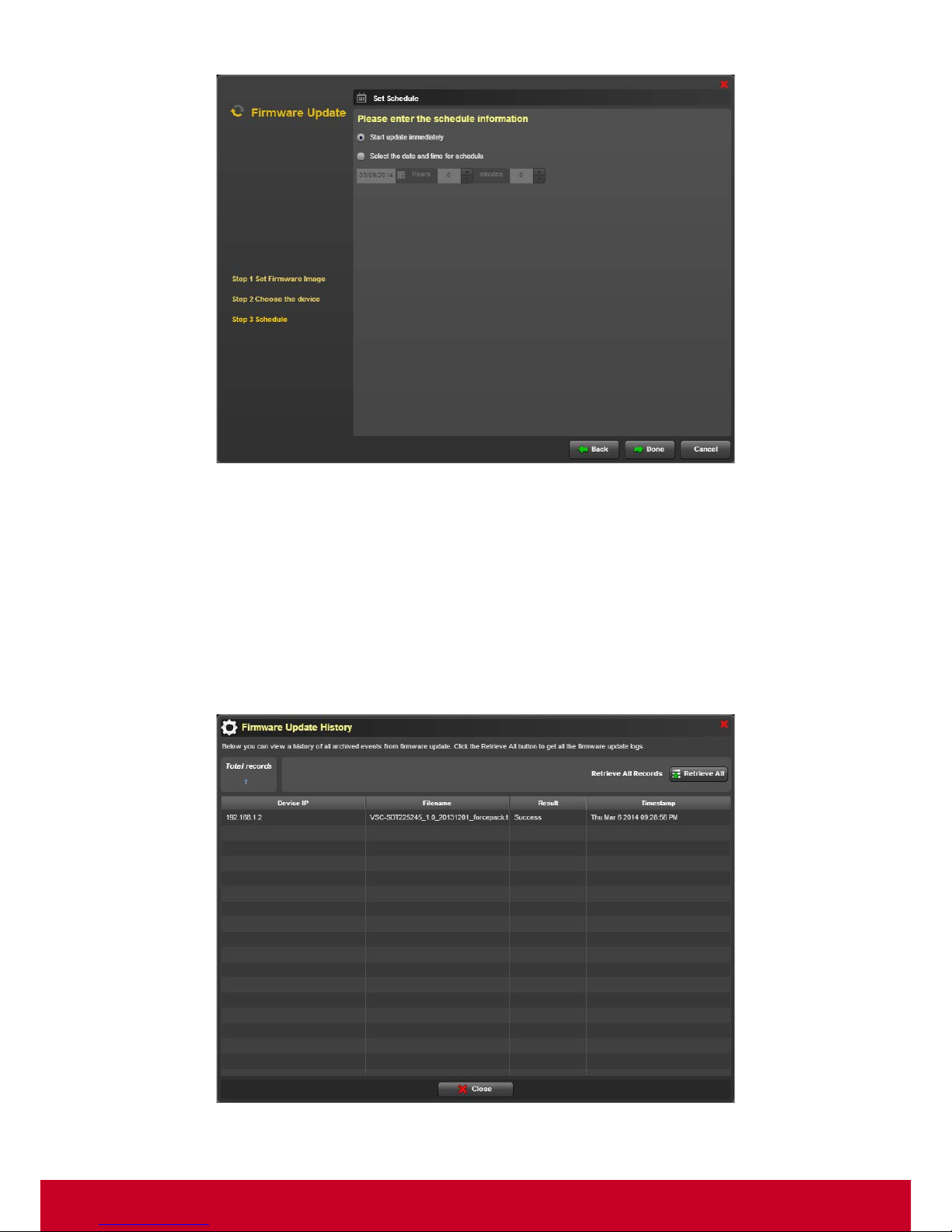
16. Click Next to move to the Schedule step as shown in the subsequent screenshot.
Page 62
61
Figure 51: Schedule
17. Select Start Firmware update immediately in order to start the firmware update immediately.
18. Choose Select the date and time for schedule in order to select a particular date and time for
the schedule to start.
19. Click Done in order to start the update process.
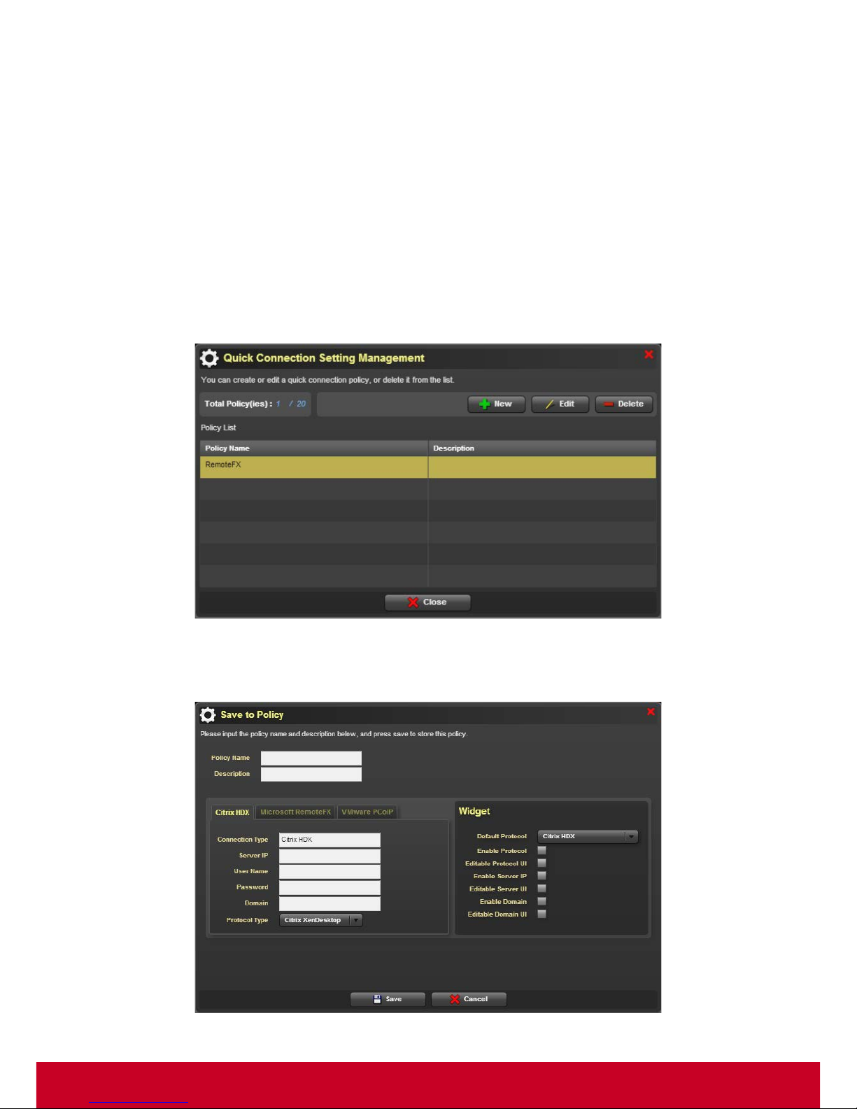
Retrieving Firmware Update History
1. Click Plugins > Smart Client Management > Firmware Manager > Firm ware History. A
Firmware Update History dialog is displayed as shown in the subsequent screen.
Figure 52: Firmware Update History
Page 63
62
2. Click Retrieve All to retrieve all archived events from firmware update. The Firmware Update
History dialog displays all the events from firmware update.
Quick Connection Policy Manager
Smart Client Management provides connection settings for HDX, RemoteFX and VMware. These
connection settings include domain, user name, password, and server IP address. SCX allows the
user to manage connection policies and deploy connections.
Follow the steps given below to manage connection policies.
Quick Connection Policy List
1. Click Plugins >Smart Client Management > Quick Connection Policy Manager > Quick Connection
Policy List. A Widget Policy Management dialog is a displayed as shown in the subsequent
screenshot.
Figure 53: Widget Policy Management
2. In Widget Policy Management dialog, click New. A Save to Policy dialog is displayed as shown
in the subsequent screenshot.
Figure 54: Save to Policy
Page 64
63
3. Enter the required policy name and description in the Policy Name and Description, respectively.
4. Enter the required system details in the System option.
5. Select the required widgets in the Widget option.
6. Click Save to save the changes done.
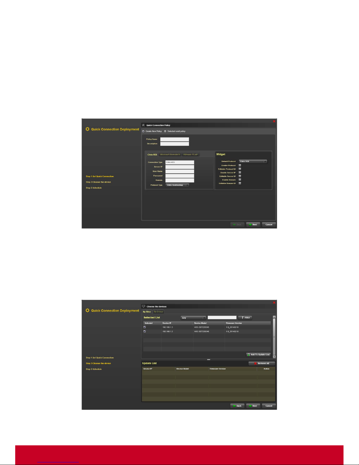
Quick Connection Deployment
1. Click Plugins >Smart Client Management > Quick Connection Policy Manager > Quick Connection
Deployment. A Quick Connection Deployment dialog is a displayed as shown in the subsequent
screenshot.
Figure 55: Quick Connection Deployment
2. Under Step 1 S et Quick Connection Setting, select Create New Policy and enter the policy
name and details in the Policy Name and Description text fields, respectively.
3. Enter the system details in the System option.
4. Select the required widgets from the Widget option.
5. Click Next to move to Step 2 Choose the Device as shown in the subsequent screenshot.
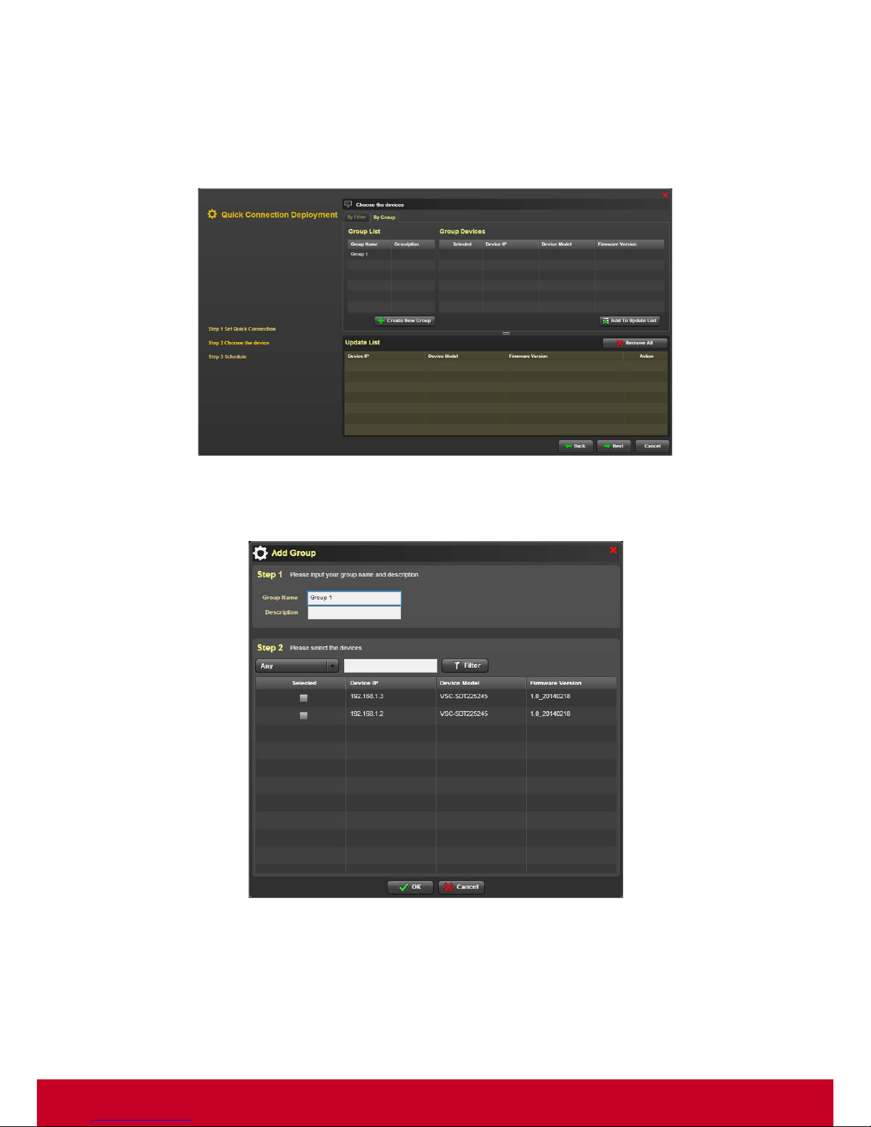
Figure 56: Connection Deployment - Choose the device
Page 65
64
6. In Choose the devices step, click By Filter tab. Select the required devices and click Add To
Update List option in order to add the devices to update list.
7. Select the required devices from the Update List and click Remove All to remove the devices
from the Update List.
8. In Choose the devices step, click By Group tab as shown in the subsequent screenshot.
Figure 57: Choose the devices - By Group
9. In order to create a group, click Create New group. Clic k Create to add a group. This opens an
Add Group dialog as shown in the subsequent screenshot.
Figure 58: Add Group
10. In Add Group dialog, under Step 1, enter the group name and description in the Group Name
and Description text fields, respectively.
11. In Step 2, select the required devices from the device list.
Page 66
65
12. Select the type of device that needs to be l isted from Any option Enter the device details in search
bar and click Filter.
13. Click OK to save the entered details.
14. In the Choose the devices step, select the required devices from the group devices list and click
Add to Update List. The selected devices will be added to the Update List.
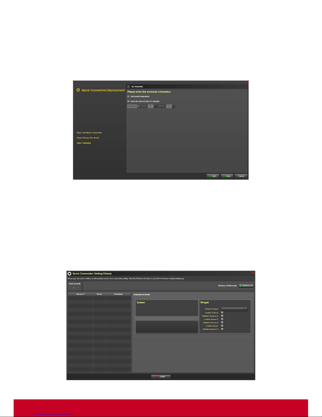
15. Click Next to move to the Step 3 Schedule as shown in subsequent screenshot.
Figure 59: Connection Deployment - Set Schedule
16. Select Start Firmware update immediately in order to start the firmware update immediately.
17. Choose Select the date and time for schedule in order to select a particular date and time for
the schedule to start.
18. Click Done in order to start the update process.
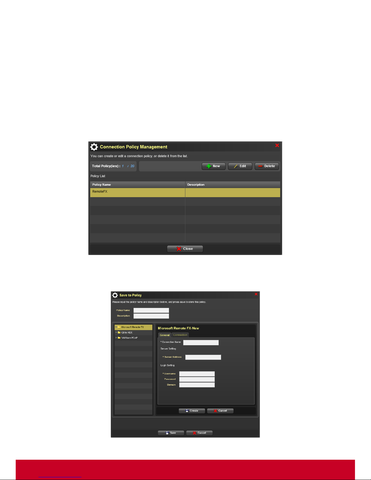
Quick Connection Setting History
1. Click Plugins > Smart Client Management > Quick Connection Policy Manager > Quick
Connection Setting History. A Quick Connection Setting History dialog is displayed as shown in
the subsequent screen.
Figure 75: Quick Connection Setting History
Page 67
66
2. Click Retrieve All to retrieve all archived events from firmware connection setting logs. The Quick
Connection Setting History dialog displays all the events from firmware connection setting logs.
Connection Manager
Smart Client Management provides advanced connection settings for RemoteFX, Citrix and VMware.
These connection settings include login setting, server setting and local resource setting. SCX allows
the user to manage connection and deploy connections.
Follow the steps given below to manage connection.
Connection List
1. Click Plugins >Smart Client Management > Connection Manager > Connection List. A Connection
Policy Management dialog is a displayed as shown in the subsequent screenshot.
Figure 60: Connection Policy Management
2. In Connection Policy Management dialog, click New. A Save to Policy dialog is displayed as
shown in the subsequent screenshot.
Figure 61: Save to Policy
Page 68
67
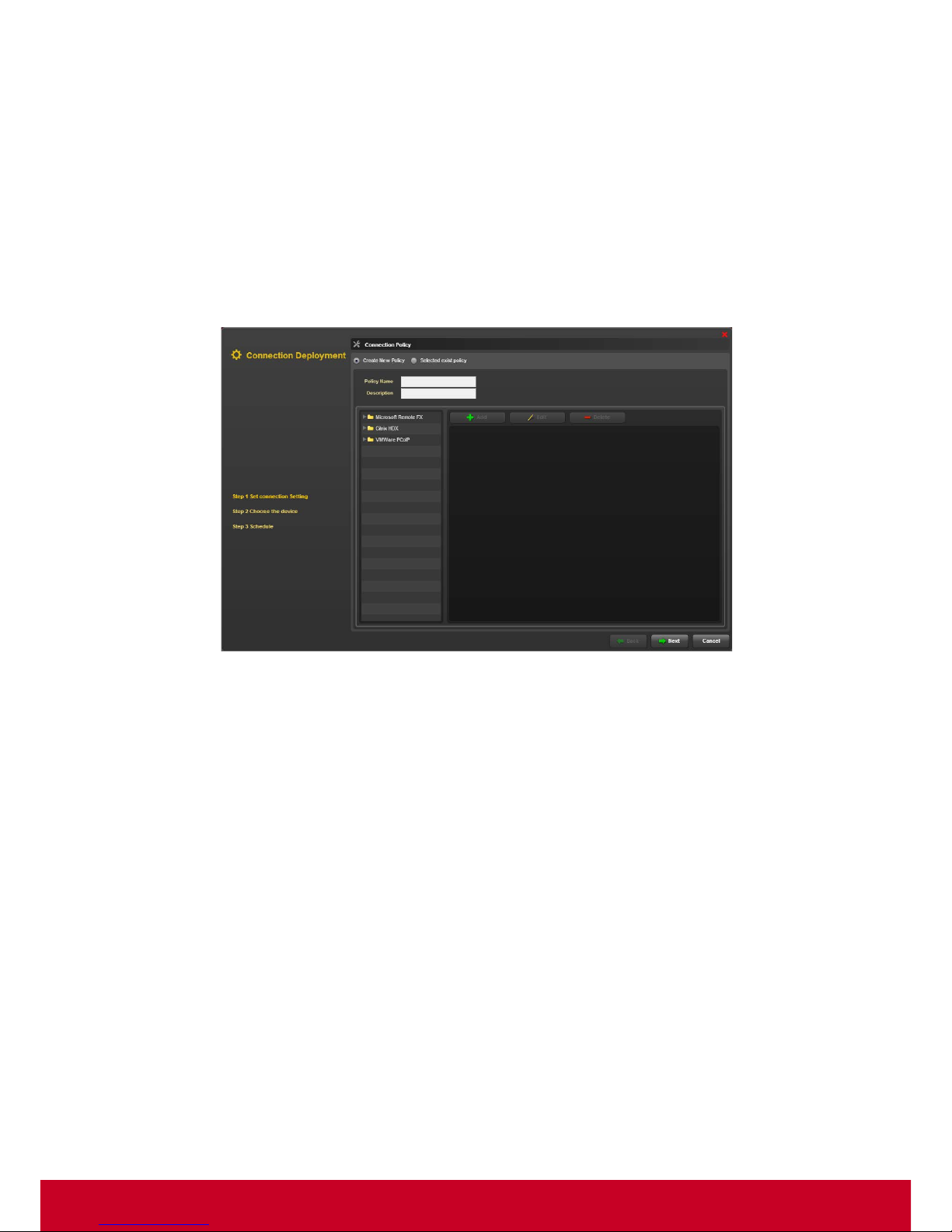
3. Enter the required policy name and description in the Policy Name and Description, respectively.
4. Click desired protocol and select Add to create a new policy.
5. Enter the required settings.
6. Click Create to create a new policy.
7. Click Save to save the policy.
Connection Deployment
1. Click Plugins >Smart Client Management > Connection Manager > Connection Deployment.
A Quick Connection Deployment dialog is a displayed as shown in the subsequent screenshot.
Figure 62: Quick Connection Deployment
2. Under Step 1 S et Quick Connection Setting, select Create New Policy and enter the policy
name and details in the Policy Name and Description text fields, respectively.
3. Click desired protocol and select Add to create a new policy.
4. Enter the required settings.
5. Click Create to create a new policy.
6. Click Next to select the deployed devices.
Page 69
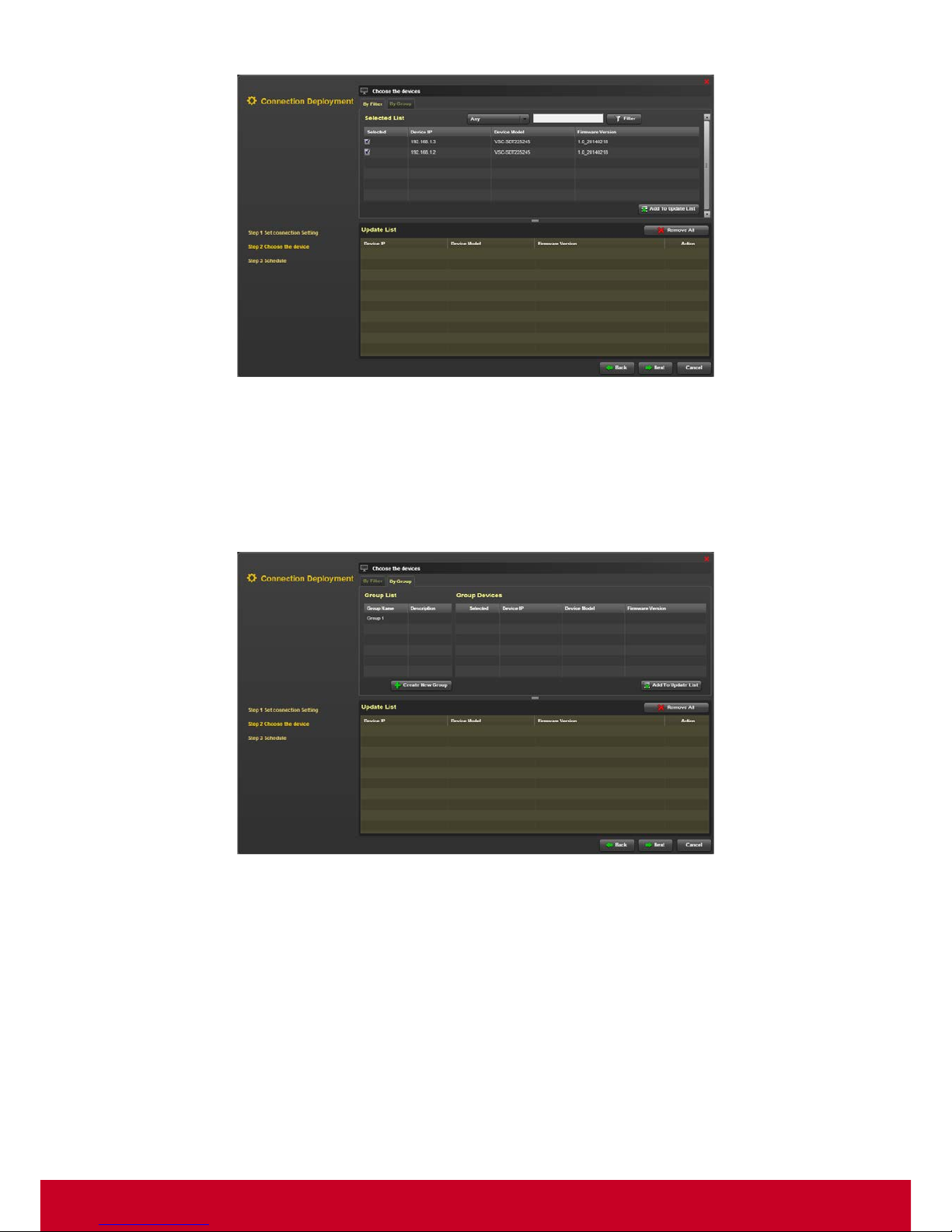
68
Figure 63: Connection Deployment - Choose the device
7. In Choose the devices step, click By Filter tab. Select the required devices and click Add To
Update List option in order to add the devices to update list.
8. Select the required devices from the Update List and click Remove All to remove the devices
from the Update List.
9. In Choose the devices step, click By Group tab as shown in the subsequent screenshot.
Figure 64: Choose the devices - By Group
10. In order to create a group, click Create New group. Click Create to add a group. This opens an
Add Group dialog as shown in the subsequent screenshot.
Page 70
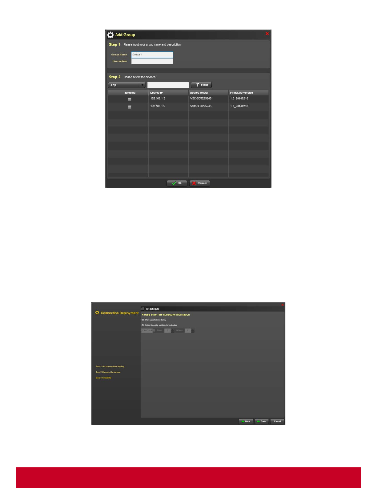
69
Figure 65: Add Group
11. In Add Group dialog, under Step 1, enter the group name and description in the Group Name
and Description text fields, respectively.
12. In Step 2, select the required devices from the device list.
13. Select the type of device that needs to be l isted from Any option Enter the device details in search
bar and click Filter.
14. Click OK to save the entered details.
15. In the Choose the devices step, select the required devices from the group devices list and click
Add to Update List. The selected devices will be added to the Update List.
16. Click Next to move to the Step 3 Schedule as shown in subsequent screenshot.
Figure 66: Connection Deployment - Set Schedule
17. Select Start Firmware update immediately in order to start the firmware update immediately.
Page 71
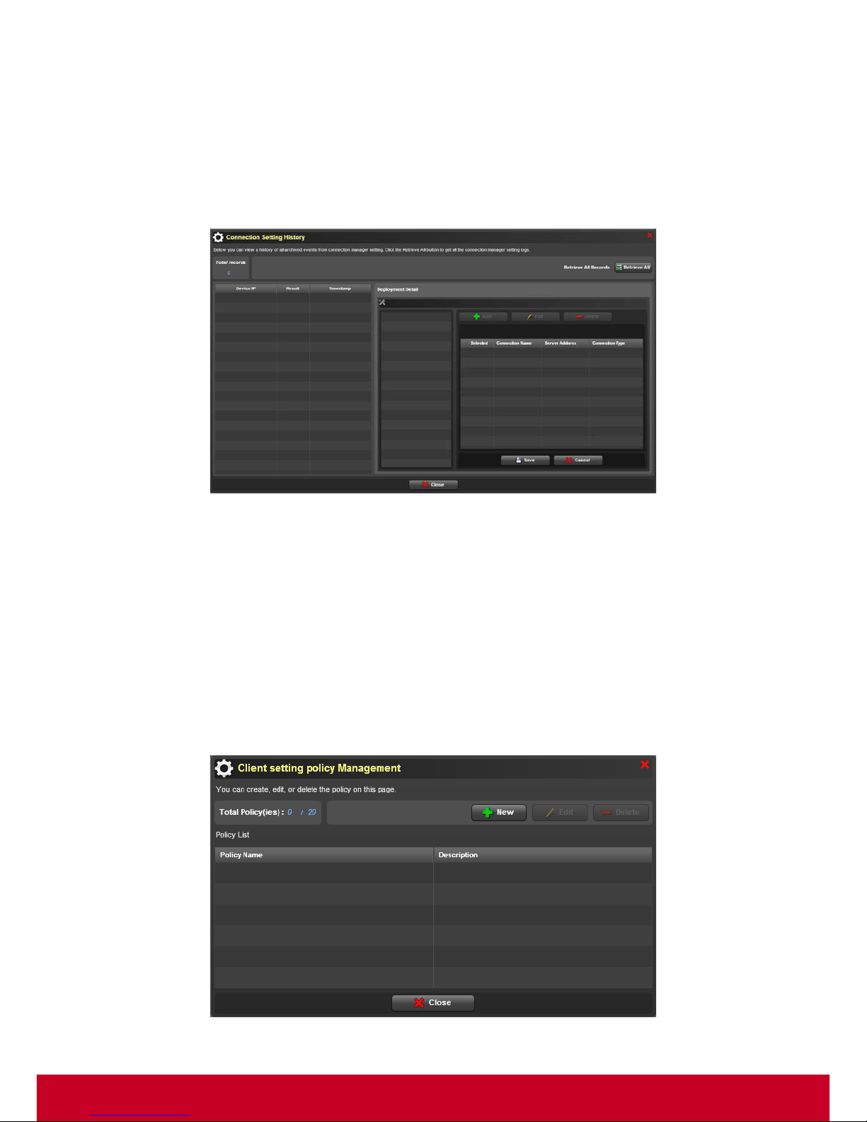
70
18. Choose Select the date and time for schedule in order to select a particular date and time for
the schedule to start.
19. Click Done in order to start the update process.
Connection Setting History
1. Click Plugins > Smart Client Management > Connection Manager > Connection Setting
History. A Connection Setting History dialog is displayed as shown in the subsequent screen.
Figure 67: Connection Setting History
2. Click Retrieve All to retrieve all archived events from firmware connection setting logs. The
Connection Setting History dialog displays all the events from firm connection setting logs.
Managing Client Policies
SCX allows the user to manage policies and deploy client connections. Follow the steps given below
to manage client policies.
Managing Client Setting Policies
1. Click Plugins > Smart Client Management > Client Policy Manager > Client Policy List. A
Client Setting Policy Management dialog is displayed as shown in the subsequent screenshot.
Figure 68: Client Setting Policy Management
Page 72
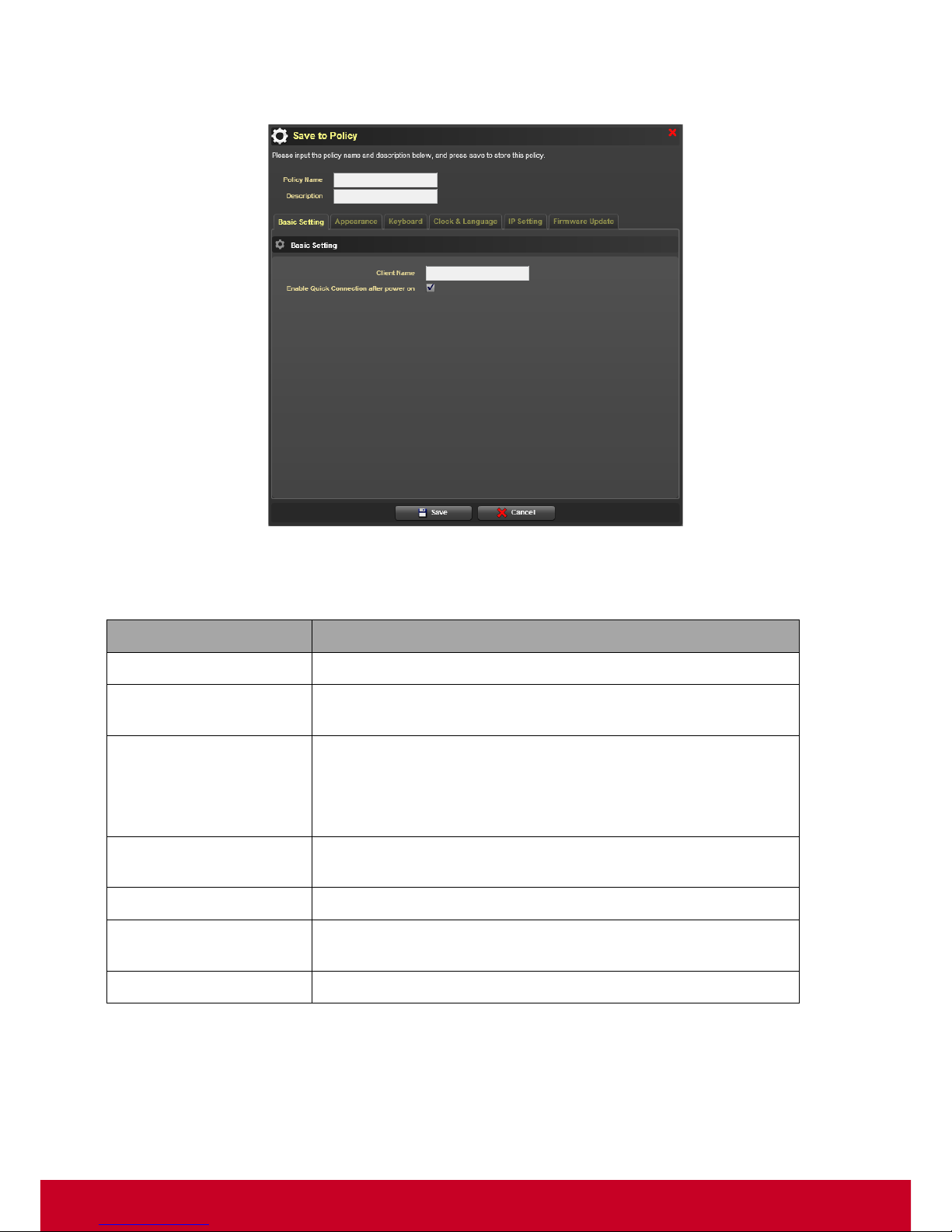
71
2. Click New t o create a new policy. A Save to Policy dialog is displayed as shown in the
subsequent screenshot.
Figure 69: Save to Policy
3. In the Save to Policy dialog, enter the required policy name and details in the Policy Name and
Description text fields, respectively.
Field
Description
Basic Setting
Options to enable quick connection after power on
Keyboard
Requires the user to select enable key repeat, show blinking,
model and layout settings.
Clock & Language
Requires the user to select the required multi-languages support
from local thin client UI.
Requires the user to select the required
Time zone settings and
sync with internal NTP server options.
Display Power
Management
Requires the user to select the option to Turn on or off monitor
(after ‘n’ minutes).
Volume
Requires the user to adjust the volume output of the system.
IP Setting
Requires the user to select the required DHCP or static IP (IP,
network mask, gateway & DNS)
Firmware Update Setting
Requires the user to select firmware location.
4. Click Basic Setting, Appearance, Keyboard, Clock & Language, IP Setting and Firmware Update
tabs and select the required options.
5. Click Save to save the details successfully.
6. In the Client Setting Policy Management dialog, select a required policy and click Edit to edit a
policy as similar to create new policy.
Page 73
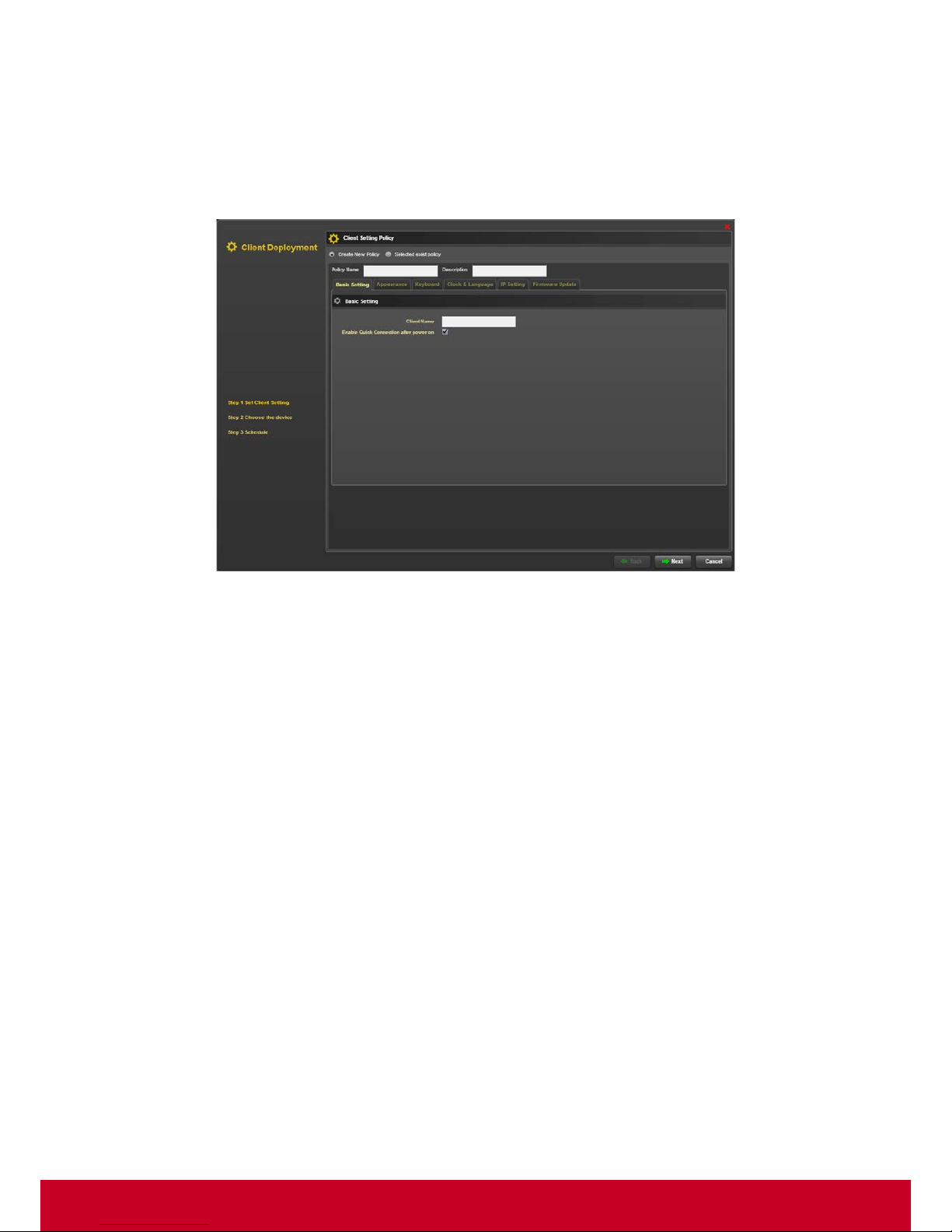
72
7. In the Client Setting Policy Management dialog, select a required policy and click Delete to
delete a policy.
Deployment Client Connections
1. Click Plugins > Smart Client Management > Client Policy Manager > Client Deployment. A Client
Deployment dialog is displayed as shown in the subsequent screenshot.
Figure 70: Client Deployment
2. Select Create New Policy and enter the required policy name and description in the Policy Name
and Description test fields, respectively.
3. Select the required options in the tabs namely Basic Setting, Appearance, Keyboard, Clock &
Language, IP Setting, and Firmware Update.
4. Select Selected exist policy in order to use an existing policy.
5. Click Next to move to Step 2 Choose the device as shown in the subsequent screenshot.
Page 74
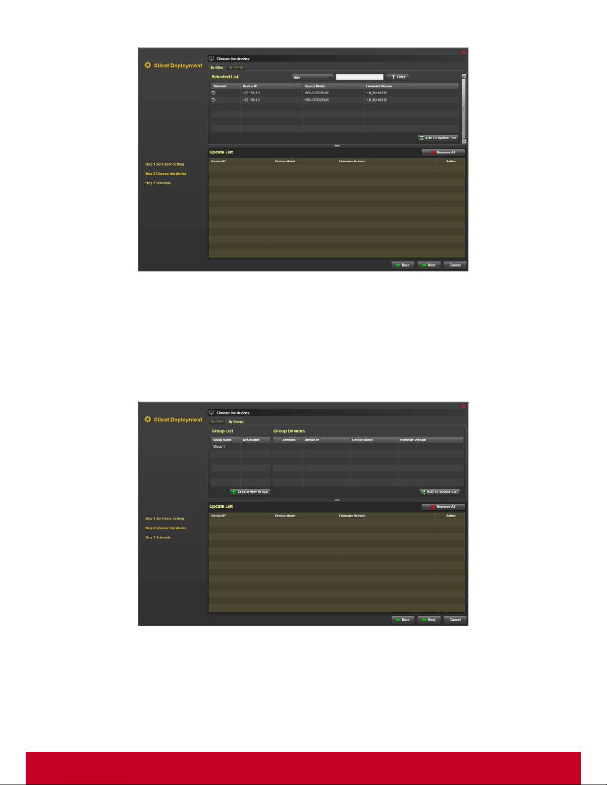
73
Figure 71: Client Deployment - Choose the devices
6. In the Choose the device step, click By Filter tab. Select the required devices and click Add to
Update List. The selected devices will be added to Update List.
7. Click the select devices from the Update List and click Remove All to remove the selected
devices from the Update List.
8. In the Choose the device step, click By Group tab as shown in the subsequent screenshot.
Figure 72: Choose the devices - By Group
9. Select the required group name from the Group List and select the required group devices. Click
Add to Update List in order to add the selected devices to the Update List.
10. In order to create a group, click Create New group. Click Create to add a group. This opens an
Add Group dialog as shown in the subsequent screenshot.
Page 75
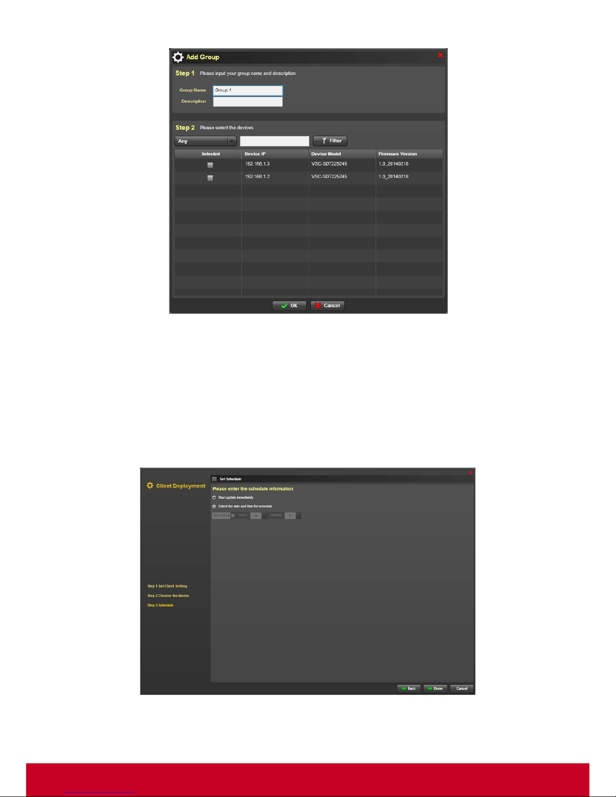
74
Figure 73: Add Group
11. In Add Group dialog, under Step 1, enter the group name and description in the Group Name
and Description text fields, respectively.
12. In Step 2, select the required devices from the device list.
13. Select the type of device that needs to be l isted from Any option Enter the device details in search
bar and click Filter.
14. Click OK to save the entered details.
15. .Click Next to move to the Schedule step as shown in the subsequent screenshot.
Figure 74: Schedule
16. Select Start Firmware update immediately in order to start the firmware update immediately.
Page 76
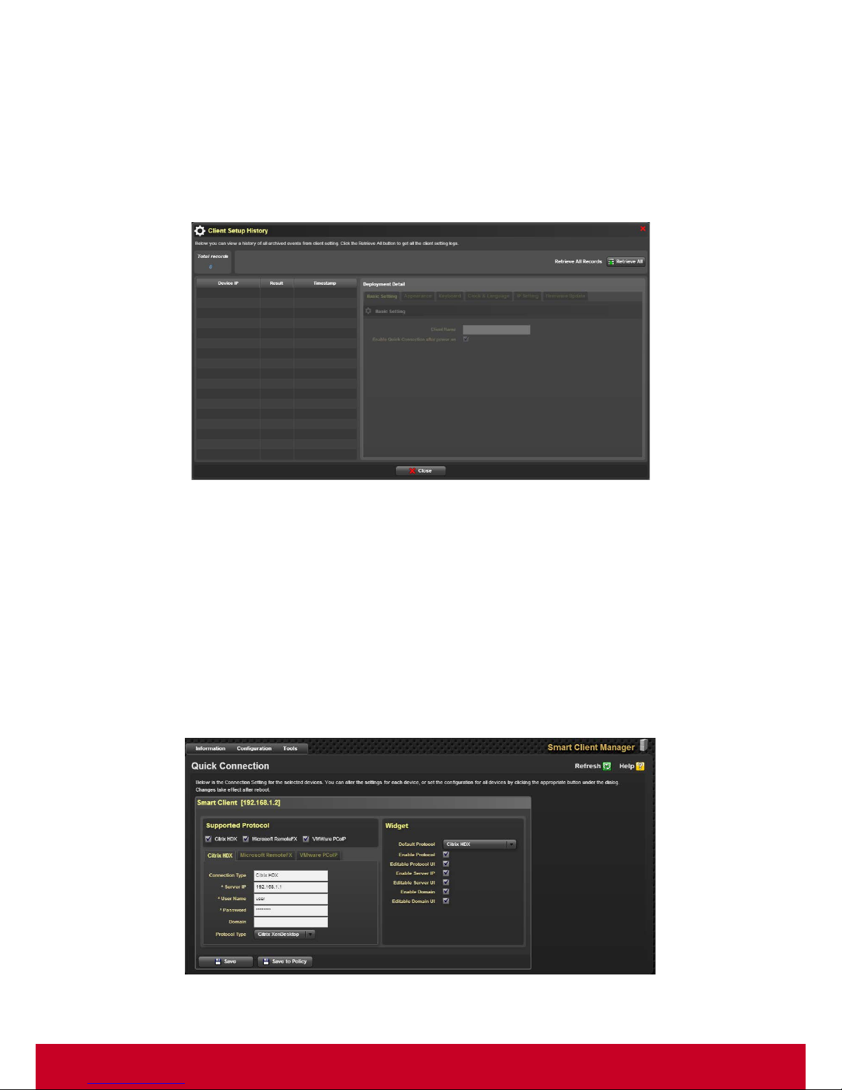
75
17. Choose Select the date and time for schedule in order to select a particular date and time for
the schedule to start.
18. Click Done in order to start the update process.
Client Setting History
1. Click Plugins > Smart Client Management > Cli ent Policy Manager > Client Setting History. A
Connection Setting History dialog is displayed as shown in the subsequent screen.
Figure 75: Connection Setting History
2. Click Retrieve All to retrieve all archived events from firmware connection setting logs. The Client
Setting History dialog displays all the events from firmware connection setting logs.
Quick Connection
Smart Client Management provides connection settin gs for HDX, RemoteFX and VMware. These
connection settings include domain, user name, password, and server IP address. SCX allows the
user to configure connection settings for the selected devices.
Follow the steps given below to configure connection settings.
1. Click Configuration > Quick Connection. A Connection Configuration page is displayed as
shown in the subsequent screenshot.
Figure 76: Connection Configuration
Page 77
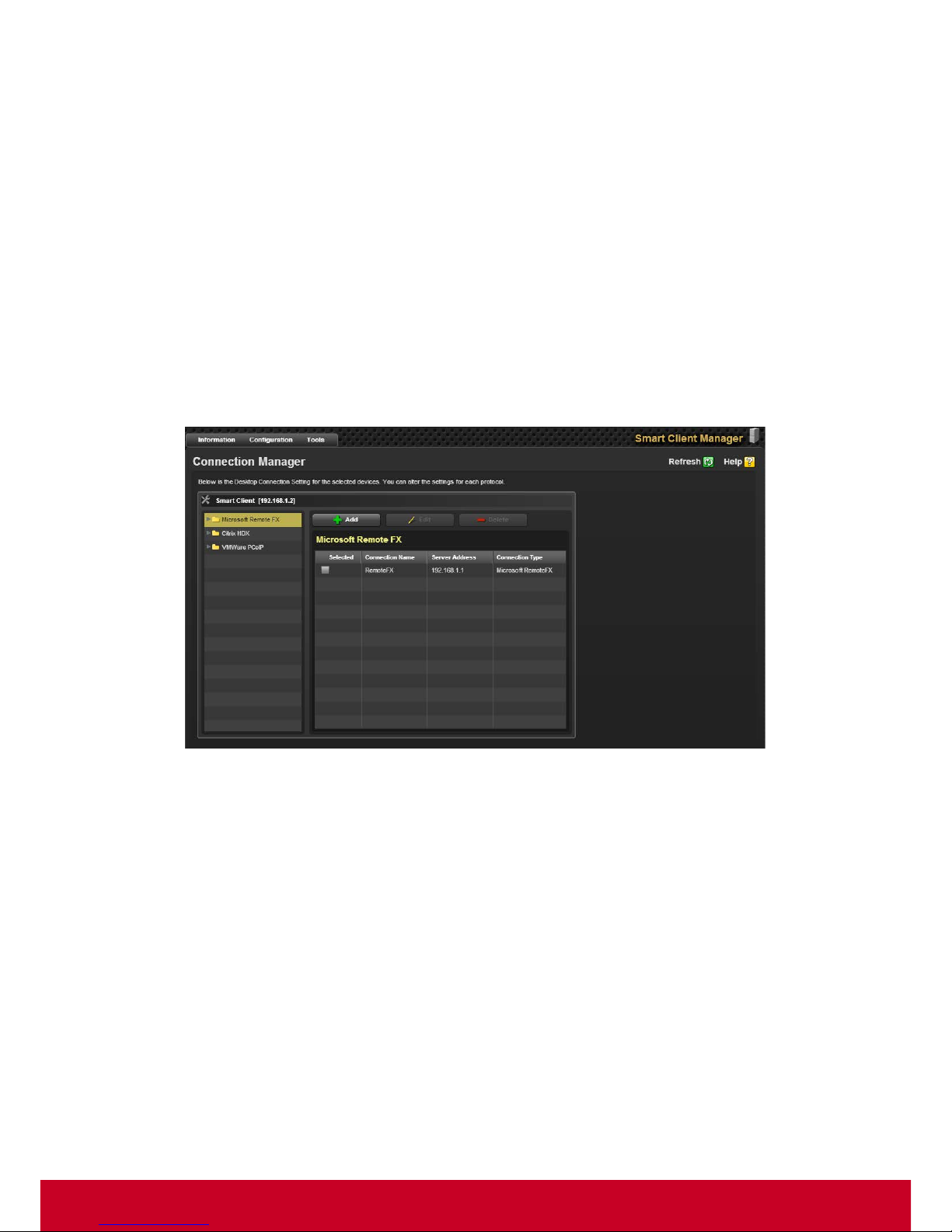
76
2. Select the required protocol options for the system in Supported Protocol settings option.
3. Entered the required information.
4. Select the required options in the Widget settings option.
5. Click Save to save the required settings.
6. Click Save to Policy to save the connection settings to a policy.
Connection Manager
Smart Client Management provides Desktop Connection Setting for the selected devices. User can
configure the settings for each protocol.
Follow the steps given below to configure Connection Manager:
1. Click Configuration > Client Setting > Connection Manager to configure Connection Manager
in client settings. A Connection Manager page is displayed as shown in the subsequent
screenshot.
Figure 77: Connection Manager
2. Select a required protocol and click Add to add a new setting for that proto col. Connection settings
for that protocol appear as shown in the subsequent screenshot.
Page 78
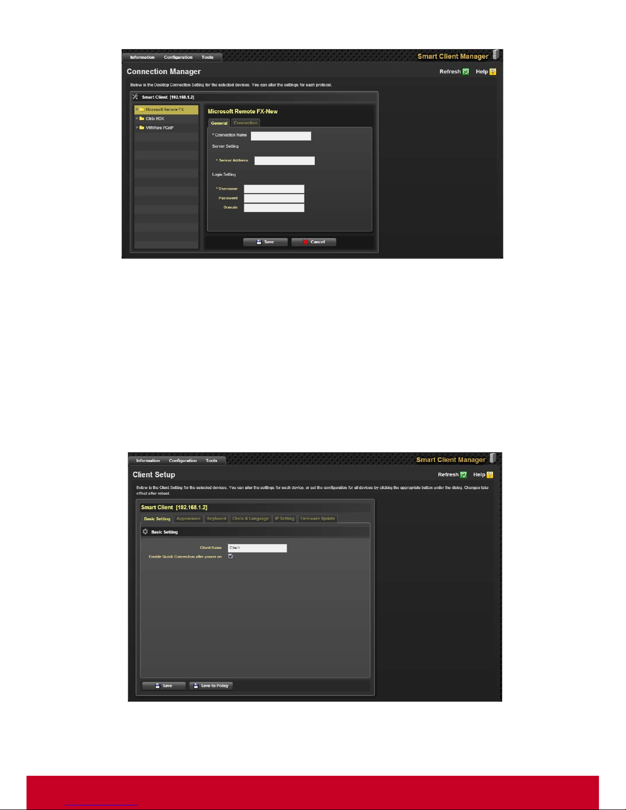
77
Figure 78: Protocol – New
3. Type the required details in the respective text boxes for the respective protocol and click Save.
4. Select the required connection and click Edit to the particular connection.
5. Type the required details and click Save.
6. Select the required connection and click Delete to delete a particular connection.
Client Setup
Follow the steps given below to configure Connection Manager:
1. Click Configuration > Client Setting > Client Setup to conf igure client settings. A Client Setup
page is displayed as shown in the subsequent screenshot.
Figure 79: Client Setup
2. Select the required client options from the tabs namely Basic Setting, Appearance, Keyboard,
Clock & Language, IP Setting and Firmware Update.
Page 79
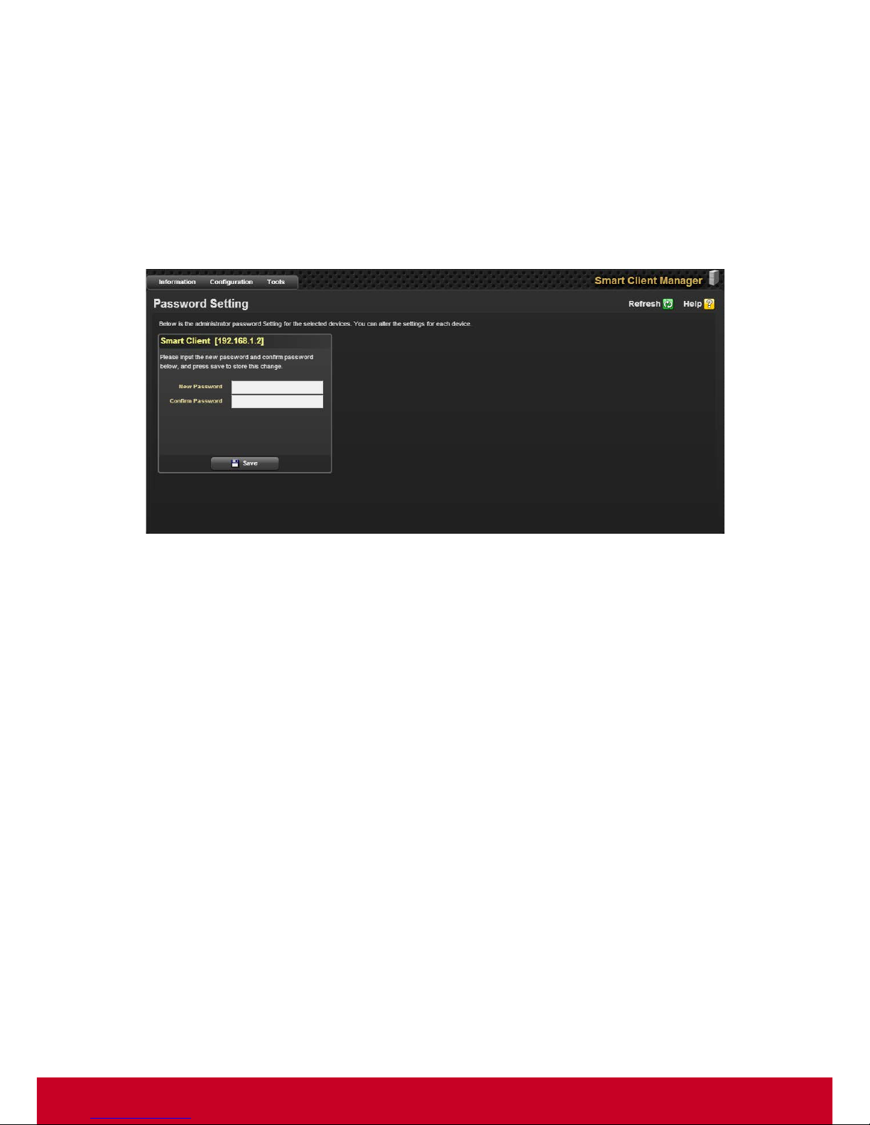
78
3. Click Save to save the settings.
4. Click Save to Policy in order to save the client connections to a policy.
Password Setting
SCX allows the user to change the admin password for local thin client configuration.
Follow the steps given below to change the password for a selected device.
1. Click Configuration > Password Setting. A Password Setting page is displayed as shown in
the subsequent screenshot.
Figure 80: Password Setting
2. Enter the new password for the selected device in New Password text field.
3. Enter the new password again in the Confirm Password text field.
4. Click Save to save the new password.
SCX Tools
SCX provides various other features namely power control, VNC connector, send message, certificate
upload and firmware update.
Power Control
Power Control feature allows the user to control the power of managed systems using SCX agent
interface from anywhere in the network. The user will also be able to power on (through WOL), power
off, reset, issue power cycle reset operations on the managed systems. This feature allows the user
to save energy by turning off the systems when they are not used and turning the systems on when
they are about to be used.
Follow the steps given below to issue power related commands.
1. Click Tools > Node Power, a Power Control page is displayed as shown in the subsequent
screenshot.
Page 80
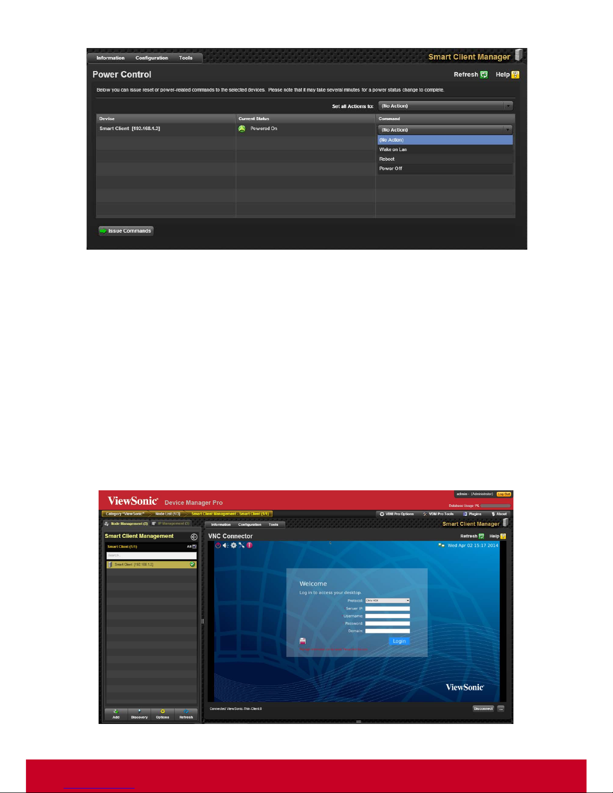
79
Figure 81: Power Control
2. Select the required commands namely Wake on LAN, Reboot and Power Off from the
command option.
3. Select the required commands namely Wake on LAN, Reboot and Power Off from the Set all
Actions to: option.
4. Click Issue Commands to issue commands for the selected commands.
VNC Connector
It is a very effective feature, if a device has the ability to control and use a remotely managed system
using a local keyboard, video and mouse. This allows the administrator to perform any management
activities without having to be physically present close to the system. SCX uses KVM redirection
feature provided by a thin client built-in VNC server to provide remote acc ess to all managed syste ms.
Follow the steps given below to connect through VNC connector.
1. Click Tools > VNC Connector, a VNC Connector page is displayed as shown in the subsequent
screenshot.
Figure 82: VNC Connector
Page 81
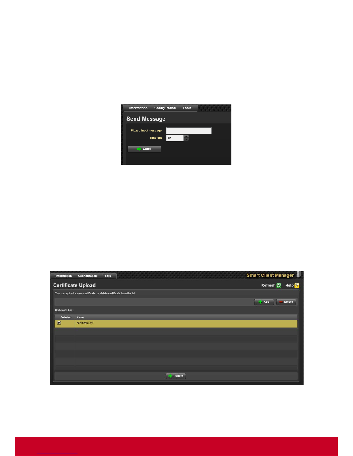
80
2. The VNC Connector page displays another device that is remotely connected through SCX.
3. Click Disconnect in order to disconnect the ongoing remote connection.
Send Message
SCX allows the user to send a message to a particular device. Follow the steps given below to send a
message.
1. Click Tools > Send Message, a Send Message page is displayed as shown in the subsequent
screenshot.
Figure 83: Send Message
2. Enter the required input message that the user wants to send in the Please input message text
field.
3. Select the required time needed for a time out in the Time out option.
4. Click Send to send the entered message.
Certificate Upload
Follow the steps given below to upload or delete a certificate.
1. Click Tools > Certificate Upload, a Certificate Upload page is displayed as shown in the
subsequent screenshot.
Figure 84: Certificate Upload
2. Click Add to upload a new certificate from a local system to selected device.
3. Select a required certificate and click Deploy to deploy the selected certificate.
Page 82
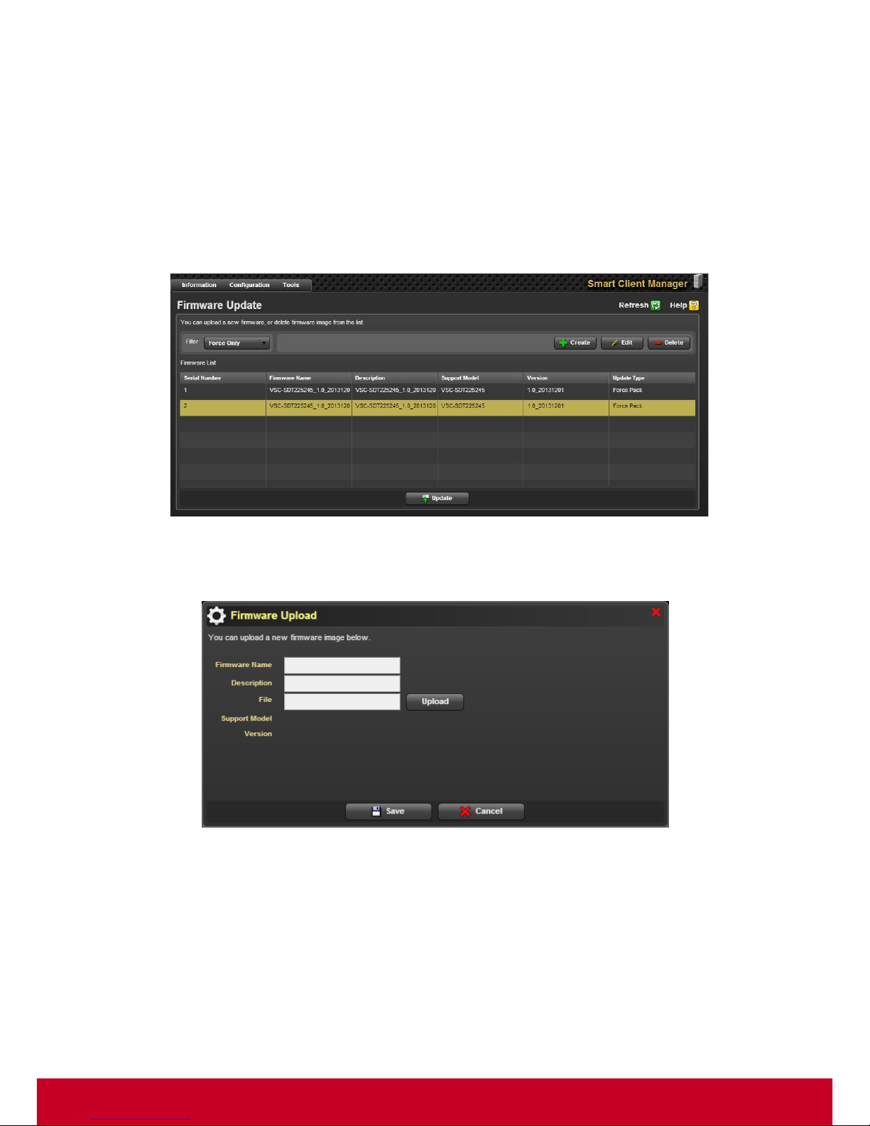
81
4. Click a particular certificate and click Delete to delete the selected certificate.
Firmware Update
Administrators have a need to update Firmware in a thin client that they manage, when a new
Firmware is available. Doing this operation on all managed systems without any automation or remote
capabilities is a difficult task. SCX simplifies this by providing options to remotely update Firmware of
multiple client systems. Follow the steps given below to upload or delete a firmware image.
1. Click Tools > Firmware Update, a Firmware Update page is displayed as shown in the
subsequent screenshot.
Figure 85: Firmware Updat e
2. Select the required filter in the Filter option. Click Create, a Firmware Upload dialog is displayed
as shown in the subsequent screenshot.
Figure 86: Firmware Upload
3. In Firmware Upload dialog, enter the firmware name and details in the Firmware and
Description text fields, respectively.
4. Click Upload to select a firmware image from the local system and upload a new firmware image.
5. Click Save to upload the firmware image successfully.
6. In the Firmware Update page, select a firmware from the firmware list and click Edit. An Edit
Firmware Information dialog is displayed as shown in the subsequent screenshot.
Page 83
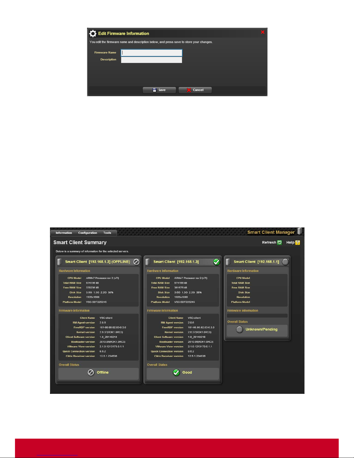
82
Figure 87: Edit Firmware Information
7. Enter the firmware name and description in the Firmware Name and Description text fields,
respectively.
8. Click Save to save the firmware information.
9. Select a required firmware from the firmware list and click Delete to delete the selected firmware
image.
10. Click Update to update the changes made so far.
General Information
In SCX, the user can get general information of the selected devices. A detailed description of the
Smart Client device is given below.
Click Information > Smart Client Summary to launch the Smart Client Summary page as shown in
the subsequent screenshot.
Figure 88: Smart Client Summary
Page 84

83
The Smart Client Summary shows the following information:
Field
Information
Hardware
Information
• CPU Model
• Total RAM Size
• Free RAM Size
• Disk Size
• Resolution
• Platform Model
Firmware
Information
• Firmware Version
• Agent Revision
• Kernel Build Version
• Kernel version
• Xloader Build Version
• Uboot Build Version
• Uboot version
• Citrix Receiver Version
• VMWare View Client Version
• Free RDP Version
• SPECClient Version
• vWorkspace Connector Version
Overall Status
Displays the overall health status of the selected device
Page 85
84
Chapter 12
Appendix
Event Logs
For Base Framework
In VDM Pro Event Logs, Event Source, Cause and Severity are explained below.
Event Source
Event source is created by a combination of defined reason codes and reason sub codes. Reason
codes are the parameters monitored by each plug-ins and reason sub codes are a special parameter
of a particular reason code.
Reason Codes
Description
General
When the user does any configurations, an event will be
logged.
User
When the user wants to con figure user account, a n event w ill be
logged.
Security
When the user wants to configure the application settings for
security purpose, an event will be logged.
Reason Sub
Codes
Description
Discovery Range
When the user wants to discover the devices, provide a discovery
range. At that point, an event will be logged.
Firmware Upgrade
When a firmware is upgraded to a higher version, that activity will
be logged as an event.
User Account
When a user creates a user account for logging into the
application with his user name and password other than the
default credentials, an event will be logged.
Login
When a user logs into the application, an event will be logged.
Login Failure
When a user provides incorrect credentials during login, an event
will be logged.
Logout
When a user logs out of the application, an event will be logged.
Session Expired
When the session is expired, an event will be logged.
SSL
When a new SSL certificate is uploaded, an event will be logged.
Page 86
85
Cause Codes
Cause codes are not specific to any plug-in, and provide a generic descriptive cause for an event.
Cause
Code
Description
Start
When an application is started, this cause will be logged.
Stop
When an application is stopped, this cause will be logged.
Pause
When an application waits for few seconds, this cause will be logged.
Resume
When an application gets started from the pause state, this cause will be
logged.
Threshold
Whenever a health of a device is in warning or critical state, this cause will
be logged.
Open
When an application is opened, this cause will be logged.
Close
When an application is closed, this cause will be logged.
Modified
When there is a change in Power status or health threshold for the devices,
this cause will be logged.
Running / In
Progress
When an application or process is in run state, this cause will be logged.
Complete
Whenever an action is completed, this cause will be logged.
Failed
When the devices go to the off state, this cause will be logged.
Succeeded
When an application is logged successfully, this cause will be logged.
Added
When a device is added in a device tree, this cause will be logged.
Removed
When the user wants the unwanted device to be removed from the device
tree, this cause will be logged.
Ignored
When the user wants the unwanted device to be ignored from the device
tree, this cause will be logged.
Restarted
When the service is restarted, this cause will be logged.
Page 87
86
Severity
Severity is not specific to any plug-in, and provides a generic descriptive cause for an event.
Severity
Description
Unknown
When the health status of the device is not known, this severity will be
logged.
Good / Normal
When the health status of the device is good or normal, this severity will be
logged.
Warning
When the health status of the device meets the warning threshold, this
severity will be logged.
Critical
When the health status of the device is in critical state, this severity will be
logged.
Non
Recoverable
When the health status of the device cannot be recovered, this severity will
be logged.
Information
Information other than health status of the device will be logged as severity.
Page 88

 Loading...