

Page 1

Pro10 Series
Professional DLP® Projector
User Guide
IMPORTANT: Please read this User Guide to obtain important information on installing
and using your product in a safe manner, as well as registering your product for
future service. Warranty information contained in this User Guide will describe your
limited coverage from ViewSonic Corporation, which is also found on our web site at
http://www.viewsonic.com in English, or in specific languages using the Regional
selection box in the upper right corner of our website. “Antes de operar su equipo lea cu
idadosamente las instrucciones en este manual”
Model No. VS15149/VS15541
Page 2

Compliance Information
FCC Statement
This equipment has been tested and found to comply with the limits for a Class A digital
device, pursuant to part 15 of the FCC Rules. These limits are designed to provide reasonable
protection against harmful interference when the equipment is operated in a commercial
environment. This equipment generates, uses, and can radiate radio frequency energy
and, if not installed and used in accordance with the instruction manual, may cause harmful
interference to radio communications.
Operation of this equipment in a residential area is likely to cause harmful interference in
which case the user will be required to correct the interference at his own expense.
Warning: You are cautioned that changes or modications not expressly approved by the
party responsible for compliance could void your authority to operate the equipment.
For Canada
CAN ICES-3(A)/NMB-3(A)
CE Conformity for European Countries
The device complies with the EMC Directive 2004/108/EC and Low Voltage Directive
2006/95/EC.
Warning -
- This product must not be used in residential areas.
- This product may cause interference if used in residential areas.
Such use must be avoided unless the user takes special measures to reduce
electromagnetic emissions to prevent interference to the reception of radio and
television broadcasts.
Following information is only for EU-member states:
The mark is in compliance with the Waste Electrical and Electronic Equipment Directive
2002/96/EC (WEEE).
The mark indicates the requirement NOT to dispose the equipment including any spent
or discarded batteries or accumulators as unsorted municipal waste, but use the return
and collection systems available.
If the batteries, accumulators and button cells included with this equipment, display
the chemical symbol Hg, Cd, or Pb, then it means that the battery has a heavy metal
content of more than 0.0005% Mercury or more than, 0.002% Cadmium, or more than
0.004% Lead.
i
Page 3

Important Safety Instructions
1. Read these instructions.
2. Keep these instructions.
3. Heed all warnings.
4. Follow all instructions.
5. Do not use this unit near water.
6. Clean with a soft, dry cloth.
7. Do not block any ventilation openings. Install the unit in accordance with the
manufacturer’s instructions.
8. Do not install near any heat sources such as radiators, heat registers, stoves, or other
devices (including ampliers) that produce heat.
9. Do not defeat the safety purpose of the polarized or grounding-type plug. A polarized plug
has two blades with one wider than the other. A grounding type plug has two blades and a
third grounding prong. The wide blade and the third prong are provided for your safety. If
the provided plug does not t into your outlet, consult an electrician for replacement of the
obsolete outlet.
10. Protect the power cord from being walked on or pinched particularly at plugs. Convenience
receptacles and the point where they exit from the unit. Be sure that the power outlet is
located near the unit so that it is easily accessible.
11. Only use attachments/accessories specied by the manufacturer.
12. Use only with the cart, stand, tripod, bracket, or table specied by the
manufacturer, or sold with the unit. When a cart is used, use caution when
moving the cart/unit combination to avoid injury from tipping over.
13. Unplug this unit when unused for long periods of time.
14. Refer all servicing to qualied service personnel. Servicing is required when the unit has
been damaged in any way, such as: if the power-supply cord or plug is damaged, if liquid
is spilled onto or objects fall into the unit, if the unit is exposed to rain or moisture, or if the
unit does not operate normally or has been dropped.
ii
Page 4

Declaration of RoHS2 Compliance
This product has been designed and manufactured in compliance with Directive 2011/65/
EU of the European Parliament and the Council on restriction of the use of certain hazardous substances in electrical and electronic equipment (RoHS2 Directive) and is deemed to
comply with the maximum concentration values issued by the European Technical Adaptation Committee (TAC) as shown below:
Substance
Lead (Pb) 0.1% < 0.1%
Mercury (Hg) 0.1% < 0.1%
Cadmium (Cd) 0.01% < 0.01%
Hexavalent Chromium (Cr6+) 0.1% < 0.1%
Polybrominated biphenyls (PBB) 0.1% < 0.1%
Polybrominated diphenyl ethers (PBDE) 0.1% < 0.1%
Proposed Maximum
Concentration
Actual Concentration
Certain components of products as stated above are exempted under the Annex III of the
RoHS2 Directives as noted below:
Examples of exempted components are:
1. Mercury in cold cathode uorescent lamps and external electrode uorescent lamps
(CCFL and EEFL) for special purposes not exceeding (per lamp):
(1) Short length (≦500 mm): maximum 3.5 mg per lamp.
(2) Medium length (>500 mm and ≦1,500 mm): maximum 5 mg per lamp.
(3) Long length (>1,500 mm): maximum 13 mg per lamp.
2. Lead in glass of cathode ray tubes.
3. Lead in glass of uorescent tubes not exceeding 0.2% by weight.
4. Lead as an alloying element in aluminium containing up to 0.4% lead by weight.
5. Copper alloy containing up to 4% lead by weight.
6. Lead in high melting temperature type solders (i.e. lead-based alloys containing 85%
by weight or more lead).
7. Electrical and electronic components containing lead in a glass or ceramic other than
dielectric ceramic in capacitors, e.g. piezoelectronic devices, or in a glass or ceramic
matrix compound.
iii
Page 5

Copyright Information
Copyright © ViewSonic® Corporation, 2013. All rights reserved.
Macintosh and Power Macintosh are registered trademarks of Apple Inc.
Microsoft, Windows, Windows NT, and the Windows logo are registered trademarks of Microsoft
Corporation in the United States and other countries.
ViewSonic, the three birds logo, OnView, ViewMatch, and ViewMeter are registered trademarks
of ViewSonic Corporation.
VESA is a registered trademark of the Video Electronics Standards Association. DPMS and
DDC are trademarks of VESA.
PS/2, VGA and XGA are registered trademarks of International Business Machines Corporation.
Disclaimer: ViewSonic Corporation shall not be liable for technical or editorial errors or omis-
sions contained herein; nor for incidental or consequential damages resulting from furnishing
this material, or the performance or use of this product.
In the interest of continuing product improvement, ViewSonic Corporation reserves the right to
change product specications without notice. Information in this document may change without
notice.
No part of this document may be copied, reproduced, or transmitted by any means, for any
purpose without prior written permission from ViewSonic Corporation.
Product Registration
To fulll possible future product needs, and to receive additional product information as it
becomes available, please visit your region section on ViewSonic’s website to register your
product online.
The ViewSonic CD also provides an opportunity for you to print the product registration form.
Upon completion, please mail or fax to a respective ViewSonic ofce. To nd your registration
form, use the directory “:\CD\Registration”. Registering your product will best prepare you for
future customer service needs.
Please print this user guide and ll the information in the “For Your Records” section.
For additional information, please see the “Customer Support” section in this guide.
For Your Records
Product Name: Pro10 Series
ViewSonic Professional DLP® Projector
Model Number: VS15149/VS15541
Document Number: Pro10 Series_UG_ENG Rev. 1A 05-06-13
Serial Number: ___________________________________________
Purchase Date: ___________________________________________
Product disposal at end of product life
The lamp in this product contains mercury which can be dangerous to you and the environment.
Please use care and dispose of in accordance with local, state or federal laws.
ViewSonic respects the environment and is committed to working and living green. Thank you
for being part of Smarter, Greener Computing. Please visit ViewSonic website to learn more.
USA & Canada: http://www.viewsonic.com/company/green/recycle-program/
Europe: http://www.viewsoniceurope.com/uk/support/recycling-information/
Taiwan: http://recycle.epa.gov.tw/recycle/index2.aspx
iv
Page 6
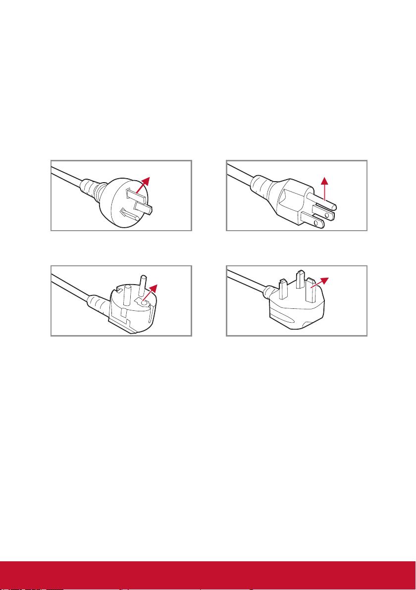
Notes on the AC Power Cord
AC Power Cord must meet the requirement of countries where you use this projector. Please
conrm your AC plug type with the graphics below and ensure that the proper AC Power Cord
is used. If the supplied AC Power Cord does not match your AC outlet, please contact your
sales dealer. This projector is equipped with a grounding type AC line plug. Please ensure
that your outlet ts the plug. Do not defeat the safety purpose of this grounding type plug. We
highly recommend using a video source device also equipped with a grounding type AC line
plug to prevent signal interference due to voltage uctuations.
Ground Ground
For Australia and Mainland China For the U.S.A and Canada
GroundGround
For Continental Europe For the U.K.
v
Page 7

Precautions
Please follow all warnings, precautions and maintenance as
recommended in this user’s guide.
▀■ Warning-
▀■ Warning-
▀■ Warning-
▀■ Warning-
▀■ Warning-
▀■ Warning-
▀■ Warning-
▀■ Warning-
▀■ Warning-
▀■ Warning-
▀■ Warning-
Do not look into the projector’s lens when the lamp is on. The
bright light may hurt your eyes.
To reduce the risk of re or electric shock, do not expose this
projector to rain or moisture.
Please do not open or disassemble the projector as this may
cause electric shock.
When replacing the lamp, please allow the unit to cool down.
Follow instructions as described on pages 65-66.
This projector will detect the life of the lamp itself. Please be
sure to change the lamp when it shows warning messages.
Reset the “Lamp Reset” function from the on-screen display
“OPTIONS | Lamp Settings” menu after replacing the lamp
module (refer to page 56).
When switching the projector off, please ensure the cooling
cycle has been completed before disconnecting power. Allow
60 seconds for the projector to cool down.
Do not use lens cap when projector is in operation.
When the lamp is approaching the end of its lifetime, the
message “Lamp Warning: Lamp life exceeded.” will show
on the screen. Please contact your local reseller or service
center to change the lamp as soon as possible.
Do not look into or point the laser pointer on your remote
control into your or someone’s eyes. Laser pointer can cause
permanent damage to eyesight.
Do not transport the projector with any lens installed.
vi
Page 8

Do:
y Turn off and unplug the power plug from the AC outlet before cleaning the
product.
y Use a soft dry cloth with mild detergent to clean the display housing.
y Disconnect the power plug from AC outlet if the product is not being used for a
long period of time.
Do not:
y Block the slots and openings on the unit provided for ventilation.
y Use abrasive cleaners, waxes or solvents to clean the unit.
y Use under the following conditions:
- In extremely hot, cold or humid environments.
` Ensure that the ambient room temperature is within 5°C ~ 40°C
` Relative humidity is 10% ~ 85%
- In areas susceptible to excessive dust and dirt.
- Near any appliance generating a strong magnetic eld.
- In direct sunlight.
vii
Page 9

Table of Contents
Precautions ............................................vi
Introduction 9
Product Features .................................... 9
Package Overview ............................... 10
Product Overview ..................................11
Main Unit ...........................................11
Control Panel ................................... 12
Connection Ports ............................. 13
Remote Control ................................ 14
Installation 16
Installing the Projector Lens ................. 16
Connecting to Computer/Notebook ...... 17
Connecting to Video Sources ............... 18
Powering On/Off the Projector ............. 19
Powering On the Projector ............... 19
Powering Off the Projector ............... 20
Warning Indicator ............................. 21
LED Lighting Message ..................... 21
Adjusting the Projected Image ............. 22
Adjusting the Projector’s Height ....... 22
Adjusting the Projecting Image’s
Position ............................................ 23
User Controls 26
Using the Control Panel ....................... 26
On-screen Display Menus .................... 27
How to operate ................................ 27
Structure .......................................... 28
PICTURE ......................................... 32
PICTURE | Advanced ...................... 34
SCREEN .......................................... 36
SCREEN | Geometry ....................... 37
SCREEN | PIP / POP ....................... 40
SETTING ......................................... 41
SETTING | Lens Function ................ 42
SETTING | Security ......................... 43
SETTING | Signal (RGB) ................. 44
SETTING | Signal (Video) ................ 45
SETTING | Audio Settings ............... 46
SETTING | Advanced ....................... 47
SETTING | Network ......................... 48
SETTING | Image Blending ............. 52
OPTIONS ......................................... 53
OPTIONS | Lamp Settings ............... 55
OPTIONS | Remote Settings ........... 56
OPTIONS | Advanced ...................... 57
Appendices 58
Troubleshooting .................................... 58
Image Problems ............................... 58
Projector Problems .......................... 61
On Screen Messages ...................... 64
Replacing the Lamp ............................. 65
Replacing the Filter .............................. 67
Compatibility Modes ............................. 68
Remote Key Code ................................ 70
RS232 Pin Assignments ....................... 71
RS232 Protocol Function List ............... 72
Ceiling Mount Installation ..................... 79
Specications ....................................... 80
Customer Support ................................ 82
Limited Warranty .................................. 83
Mexico Limited Warranty ...................... 85
8
Page 10

Introduction
Product Features
` XGA (1024x768) / WXGA(1280x800), support resolution: Up to WUXGA
@60Hz (Reduced Blanking) and UXGA @60Hz
` Single lamp system
` Power Zoom/Focus
` Power lens shift
` Dynamic Aperture
` 10W x 1 speaker
` Filter module
` Support PIP/POP function
` Support network management for remote control and monitoring
9
Page 11

Package Overview
Unpack and inspect the box contents to ensure all parts listed below are in
the box. If something is missing, please contact our customer service.
Projector with lens cover
Power On
Pattern
Standby
VGA
HDMI
Video
BNC
DVI
S-Video
Sync
Source
Blank
Vol +
Exit Mute
Vol -
LENS
Menu Memory
Focus ShiftZoom
Mode
Lamp PW
RGB Gain
123
PIP
BlendGeo
456
Aspect
Keystone
MyButton
789
Reset
RC ID
0
Remote Control
Documentation:
y User’s Manual (CD)
y Quick Start Card
y Warranty Card (China only)
Power Cord
AA
AA
AA Batteries x 2
(For remote control)
VGA Cable
Plug for wired remote at
projector side
Φ 3.5mm phone jack
Plug for wired remote at
remote control side
Φ 2.5mm phone jack
Due to different applications in each Country, some regions may have different accessories.
10
Page 12

Product Overview
Main Unit
1
2
3
4
3
5
(Front View)
11
6
7
8
9
1. Lens Ring
2. Zoom Lens
3. IR Receivers
4. LED Indicators
5. Lamp Door
Do not block projector in/out air vents and keep 30cm clearance around vents for air ow concern.
10
(Rear View)
6. Outlet Vent
7. Kensington Lock
8. Security Bar
9. Power Switch
10. Power Connector
Min.
30cm
Min.
30cm
Min.
30cm
12
13
14
11. Connector Panel
12. Inlet Vent & Filter
13. Audio Vent
14. Keypad Panel
11
Page 13
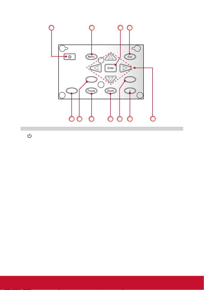
Control Panel
Shift
65
1. / Power key & Power LED
2. Menu key
3. Enter key
4. Exit key
5. Shift key
6. Sync key
7. Focus key
8. Zoom key
9. Source key
10. Information key
11. Four directional select keys
Sync
2
7
8
4
31
Source
9
10
11
12
Page 14

Connection Ports
321
7 9
8
1. Composite Video Input Connector
2. HDMI Connector
3. DVI-D Connector
4. BNC Connector
5. Wired Remote Input Connector
6. 12V Trigger Relay Connector
7. RJ45 Network Connector
8. S-Video Input Connector
9. VGA Input Connector
10. VGA Output Connector
11. Audio Input Connector
12. Audio Output Connector
13. RS232 Connector (9-pin DIN Type)
64 5
10 11 1312
13
Page 15

Remote Control
1. Power ON
Power on the projector.
2. Pattern
Display a test pattern.
3. VGA
Switch to VGA source.
4. BNC
Switch to Component video
source.
5. Sync
Synchronize projector with
source.
6. Blank
Switch to a blank screen.
7. Four Directional Select Keys
Press up, down, left, right
direction buttons to select
items or make adjustments.
8. Exit
Exit a menu.
9. Menu
Launch the OSD main menu.
10. Focus
Adjust the lens focus.
11. Lamp PW
Adjust lamp power.
12. PIP
Launch the Picture-in-Picture
function.
13. MyButton
Launch a user-dened
setting.
14. RC ID
Set the remote control ID.
15. Reset
Reset the projector to factory
default settings.
16. Standby
Turn off the projector.
17. Video
Switch to Composite Video
source.
1
Video
S-Video
Blank
Vol +
Vol -
RGB Gain
Keystone
Reset
Power On
Standby
HDMI
DVI
Source
LENS
Mode
BlendGeo
Aspect
0
2
3
4
5
6
7
8
9
10
11
12
13
14
15
Pattern
VGA
BNC
Sync
Exit Mute
Menu Memory
Focus ShiftZoom
Lamp PW
123
PIP
456
MyButton
789
RC ID
16
17
18
19
20
21
22
23
24
25
26
27
28
29
30
31
32
33
34
14
Page 16

18. HDMI
Switch to HDMI source.
19. S-Video
Switch to S-Video source.
20. DVI
Switch to DVI source.
21. Source
Automatically scans for connected source.
22. Enter
Conrm your item selection.
23. Mute
Turn the projector audio off/on.
24. Memory
Save the current lens settings to the memory.
25. Zoom
Adjust the lens zoom function.
26. Shift
Adjust the lens shift up/down/left/right.
27. RGB Gain
Enter the color management setting page.
28. Mode
Select the display mode (Presentation, Bright, Movie, sRGB, DICOM SIM, and
User).
29. Geo
Enable Geo tag information.
30. Blend
Adjust display blend function.
31. Keystone
Adjust image distortion caused by tilting the projector.
32. Aspect
Adjust the aspect ratio of the projected screen.
33. Information (i)
Display the projector information.
34. Numeric Keypad
Press “0~9” to input a numeric value such as a password in the “Security”
settings.
When using the number keypad for password input, do not use “0” as part of the password.
15
Page 17
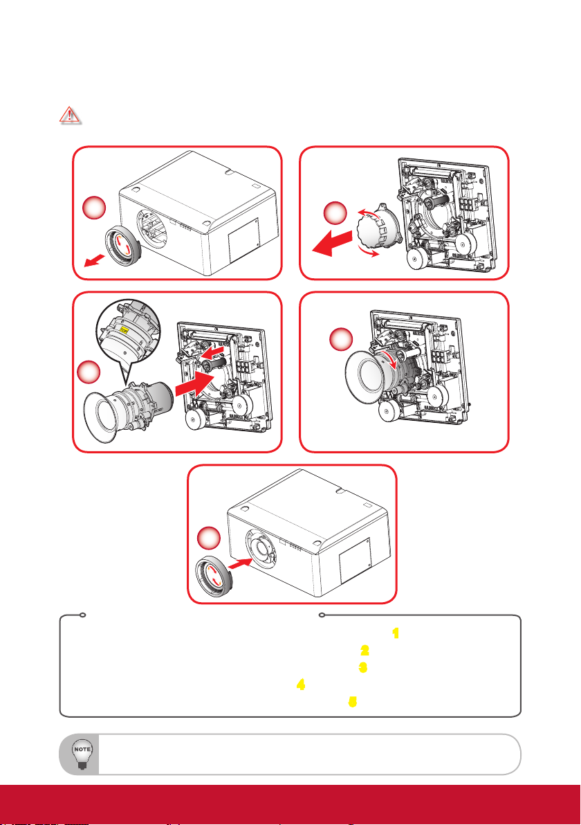
Installation
Installing the Projector Lens
Warning: Do not transport the projector with any lens installed.
1
2
4
3
5
Lens Installing Procedure:
1. Remove the lens ring cover by counter-clockwise rotation. 1
2. Remove the lens cap by counter-clockwise rotation.
3. Pull the release bar and push the lens into position.
4. Lens assembled by clockwise rotation.
5. Lens ring cover assembled by clockwise rotation.
Before installing or replacing the lens, switch off the power of the projector.
Avoid using the remote control or projector keypad button to adjust the lens shift or zoom/focus while the
lens is being attached.
4
16
2
3
5
Page 18

Connecting to Computer/Notebook
Computer / Notebook
1
2
3
4
+12V Output
5
6
7
8
Monitor
Plug for 12V DC jack
Plug for wired remote
at projector side
Plug: ID Φ 1.7mm
OD Φ 4.0mm
1. RS232 Cable
2. VGA Cable
3. DVI-D Cable
4. HDMI Cable
Φ 3.5mm
phone jack
Power
Signal
Ground
6. Audio Cable
7. RJ45 Cable
8. VGA Cable
9. Power Cord
Φ 2.5mm
phone jack
5. 12V DC Jack
Due to the difference in applications for each country, some regions may have different accessories.
R
9
Power socket
Plug for wired remote
at remote control side
Power
Signal
Ground
17
Page 19
Connecting to Video Sources
S-Video output
DVD player
1
2
DVD player, Set-top box,
HDTV receiver
3
R
6
1. Composite Video cable
2. S-Video Cable
3. BNC Cable
Due to the difference in applications for each country, some regions may have different accessories.
4
DVD player Audio output
5
4. HDMI Cable
5. Audio Cable
6. Power Cord
18
Power socket
Page 20

Powering On/Off the Projector
Powering On the Projector
1. Securely connect the power cord and signal cable. Power on the switch 1 and
the Power LED ashes Blue.
2. Turn on the lamp by pressing the “
projector or on the remote control
The startup screen will display in approximately 10 seconds. The rst time you
use the projector, you will be asked to select the preferred language and power
saving mode.
3. Turn on and connect the source that you want to display on the screen
(computer, notebook, video player, etc). The projector will detect the source
automatically. If not, push the menu button and go to “OPTIONS”.
Make sure that “Auto Source” has been set to “Off”.
` If you connect multiple sources at the same time, press the direct source
buttons on the control panel or on the remote control to switch between
inputs.
1
” button either on the control panel of the
2. The Power LED will turn blue.
Power On
Pattern
Standby
VGA
HDMI
Video
BNC
DVI
S-Video
Sync
Source
Blank
Vol +
2
Sync
Shift
Turn on the projector rst and then select the signal sources.
Source
19
Exit Mute
Vol -
Menu Memory
Focus ShiftZoom
Lamp PW
RGB Gain
123
PIP
456
Keystone
MyButton
789
Reset
RC ID
LENS
Mode
BlendGeo
Aspect
0
Page 21
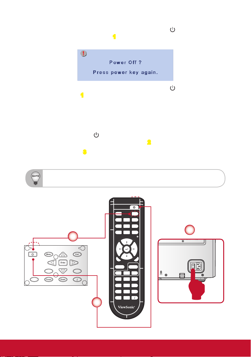
Powering Off the Projector
1. Press the “Standby” button on the remote control or the “ ” button on the control panel to turn off the projector
the screen.
Press the “Standby” button on the remote control or the “ ” button on the
control panel again 1 to conrm otherwise the message will disappear after 15
seconds. When you press for the second time, the projector will shut down.
2. The cooling fans will complete the cooling cycle for about 60 seconds and the
POWER LED will ash Blue. The projector has entered standby mode.
If you wish to turn the projector back on, you must wait until the projector has
completed the cooling cycle and has entered standby mode. Once in standby
mode, simply press the “
or on the remote control to restart the projector. 2
3. Power off the switch
3.
4. Disconnect the power cord from the electrical outlet and from the projector.
Do not turn on the projector immediately following the power of procedure.
1. The following message will be displayed on
” button either on the control panel of the projector
Power On
Pattern
Standby
VGA
HDMI
Video
BNC
DVI
S-Video
Sync
Source
Blank
1
Sync
Shift
Source
2
Vol +
Exit Mute
Vol -
Menu Memory
Focus ShiftZoom
Lamp PW
RGB Gain
123
PIP
456
Keystone
MyButton
789
Reset
RC ID
LENS
Mode
BlendGeo
Aspect
0
3
20
Page 22

Warning Indicator
When the warning indicators (see below) come on, the projector will automatically
shutdown:
y “LAMP” LED indicator is lit red and the “ERROR” LED indicator ashes red. This
indicates that the lamp has failed.
y “TEMP” LED indicator is lit red and the “ERROR” LED indicator ashes red. This
indicates the projector has overheated. Under normal conditions, the projector
can be switched back on.
y “TEMP” LED indicator ashes red and the “ERROR” LED indicator ashes red.
This indicates that the fan has failed.
y “ERROR” LED indicator ashes red and the “FILTER” LED indicator ashes red.
This indicates that the lter needs replacement.
y “FILTER” LED indicator ashes red. This indicates that the lter needs to be
cleaned.
Unplug the power cord from the projector, wait for 30 seconds and try again. If the
warning indicator light up again, please contact your nearest service center for
assistance.
LED Lighting Message
Message
Standby State
(LAN off)
Standby State
(LAN On)
Power on & Lamp
lighting
Power off (Cooling) Flashing
Error (Lamp fail) Steady light Flashing
Error (Over Temp) Steady light Flashing
Error (Fan fail) Flashing Flashing
Error (Filter Switch) Flashing Flashing
Error (Filter Cleaning) Flashing
Power LED Lamp LED Temp LED Error LED Filter LED
Red Blue Red Red Red Red
Flashing
Flashing
Steady light
21
Page 23

Adjusting the Projected Image
Adjusting the Projector’s Height
The projector is equipped with elevator rubber feet for adjusting the image
height.
1. Locate the adjustable foot you wish to modify on the underside of the projector.
2. Rotate the adjustable ring clockwise to raise the projector or counter clockwise
to lower it. Repeat with the remaining feet as needed.
1 2
22
Page 24

Adjusting the Projecting Image’s Position
HH
To determine where to position the projector, consider the size and shape of your
screen, the location of your power outlets, and the distance between the projector
and the rest of your equipment.
H1 Width
H1
V1
V
Screen
Height
V
V1
Platform H V H1 V1
XGA 15% 50% 0% 20%
WXGA 15% 50% 10% 30%
For XGA
Platform XGA (4:3)
DMD 0.7”
Projection Lens LEN-008 LEN-009 LEN-010
Wide Zoom Standard Long Zoom
Throw Ratio 0.99-1.26 1.26-1.58 1.58-3.00
Zoom Ratio 1.28X 1.25X 1.9X
Throw Distance 1.01~7.68m 1.28~9.63m 1.61~18.29m
Projection screen size Projection distance (m)
Throw Ratio 0.99 1.26 1.26 1.58 1.58 3.00
Diagonal
(inch)
50 0.76 1.02 1.01 1.28 1.28 1.61 1.61 3.05
60 0.91 1.22 1.21 1.54 1.54 1.93 1.93 3.66
70 1.07 1.42 1.41 1.79 1.79 2.25 2.25 4.27
Height
(m)
Width
(m)
Min
(m)
Max
(m)
Min
(m)
Max
(m)
Min
(m)
Max
(m)
23
Page 25

80 1.22 1.63 1.61 2.05 2.05 2.57 2.57 4.88
90 1.37 1.83 1.81 2.30 2.30 2.89 2.89 5.49
100 1.52 2.03 2.01 2.56 2.56 3.21 3.21 6.10
110 1.68 2.24 2.21 2.82 2.82 3.53 3.53 6.71
120 1.83 2.44 2.41 3.07 3.07 3.85 3.85 7.32
130 1.98 2.64 2.62 3.33 3.33 4.17 4.17 7.92
140 2.13 2.84 2.82 3.58 3.58 4.49 4.49 8.53
150 2.29 3.05 3.02 3.84 3.84 4.82 4.82 9.14
160 2.44 3.25 3.22 4.10 4.10 5.14 5.14 9.75
170 2.59 3.45 3.42 4.35 4.35 5.46 5.46 10.36
180 2.74 3.66 3.62 4.61 4.61 5.78 5.78 10.97
190 2.90 3.86 3.82 4.86 4.86 6.10 6.10 11.58
200 3.05 4.06 4.02 5.12 5.12 6.42 6.42 12.19
250 3.81 5.08 5.03 6.40 6.40 8.03 8.03 15.24
300 4.57 6.10 6.04 7.68 7.68 9.63 9.63 18.29
For WXGA
Platform WXGA (16:10)
DMD 0.65”
Projection Lens LEN-008 LEN-009 LEN-010
Wide Zoom Standard Long Zoom
Throw Ratio 1.00-1.28 1.28-1.61 1.60-3.07
Zoom Ratio 1.28X 1.25X 1.9X
Throw Distance 1.08~8.27m 1.38~10.40m 1.72~19.84m
Projection screen size Projection distance (m)
Throw Ratio 1.00 1.28 1.28 1.61 1.60 3.07
Diagonal
(inch)
50 0.67 1.08 1.08 1.38 1.38 1.73 1.72 3.31
60 0.81 1.29 1.29 1.65 1.65 2.08 2.07 3.97
70 0.94 1.51 1.51 1.93 1.93 2.43 2.41 4.63
80 1.08 1.72 1.72 2.21 2.21 2.77 2.76 5.29
90 1.21 1.94 1.94 2.48 2.48 3.12 3.10 5.95
100 1.35 2.15 2.15 2.76 2.76 3.47 3.45 6.61
110 1.48 2.37 2.37 3.03 3.03 3.81 3.79 7.27
120 1.62 2.58 2.58 3.31 3.31 4.16 4.14 7.94
130 1.75 2.80 2.80 3.58 3.58 4.51 4.48 8.60
140 1.88 3.02 3.02 3.86 3.86 4.85 4.82 9.26
150 2.02 3.23 3.23 4.14 4.14 5.20 5.17 9.92
160 2.15 3.45 3.45 4.41 4.41 5.55 5.51 10.58
Height
(m)
Width
(m)
Min
(m)
Max
(m)
Min
(m)
Max
(m)
Min
(m)
Max
(m)
24
Page 26

170 2.29 3.66 3.66 4.69 4.69 5.90 5.86 11.24
180 2.42 3.88 3.88 4.96 4.96 6.24 6.20 11.90
190 2.56 4.09 4.09 5.24 5.24 6.59 6.55 12.56
200 2.69 4.31 4.31 5.51 5.51 6.94 6.89 13.23
250 3.37 5.38 5.38 6.89 6.89 8.67 8.62 16.53
300 4.04 6.46 6.46 8.27 8.27 10.40 10.34 19.84
25
Page 27

User Controls
Using the Control Panel
Sync
Shift
Name
Power
Menu Launch the on-screen display (OSD).
Exit Exit a menu.
Enter Conrm a selected item.
Four Directional
Select Keys
Sync Synchronize the projector with the input source.
Source Select an input signal.
Shift Adjust the lens shift up/down/left/right.
Focus Adjust the lens focus function.
Zoom Adjust the lens zoom function.
Information Display the projector’s information.
Turn the projector on/off.
1. Use ▲▼◄► to select items or make adjustments to your
selection.
2. ▲/▼act as short hot keys for Keystone +/- adjustment.
Description
Source
26
Page 28

On-screen Display Menus
The Projector has multilingual On-screen Display menus that allow you to
make image adjustments and change a variety of settings. The projector
will automatically detect the source.
How to operate
1. To open the OSD menu, press “Menu” on the Remote Control or Control Panel.
2. When OSD is displayed, use ▲▼ keys to select any item in the main menu.
While making a selection on a particular page, press “Enter” key to enter sub
menu.
3. Use ▲▼ keys to select the desired item in the sub menu and then press “Enter”
key to view further settings. Adjust the settings by ◄► key.
4. Select the next item to be adjusted in the sub menu and adjust as described
above.
5. Press “Enter” to conrm, and the screen will return to the main menu.
6. To exit, press “Menu” again. The OSD menu will close and the projector will
automatically save the new settings.
Main Menu
Sub Menu
Setting
27
Page 29

Structure
Please note that the on-screen display (OSD) menus vary according to the signal type selected and the
projector model you are using.
Main Menu Sub Menu Settings
Presentation / Bright / Movie / sRGB /
DICOM SIM. / User
White / Light Yellow / Light Blue / Pink /
Dark Green
TM
On / Off
Film / Video / Graphics / Standard
On / Off
Warm / Medium / Cool
Auto / RGB / YUV
Red Gain / Green Gain / Blue Gain / Red
Bias / Green Bias / Blue Bias / Reset /
Exit
HDMI / DVI / VGA / BNC / S-Video /
Video / Exit
4:3 / 16:9 / Native / Auto
4:3 / 16:10 / Native / Auto
Off / On
Off / On
Horizontal / Vertical / Pin Cushion/Barrel
/ Reset / Exit
Corner / X Offset / Y Offset / Reset / Exit
Point 1 / Point 2 / Point 3 / Point 4 / Point
5/ Point 6 / Point 7 / Point 8 / Point 9 /
Reset / Exit
Rotation / Pin Cushion/Barrel / Reset /
Exit
PICTURE
SCREEN
Color Mode
Wall Color
Brightness
Contrast
Sharpness
Saturation
Tint
Noise Reduction
BrilliantColor
Gamma
DynamicBlack
Color Temp.
Advanced
Color Space
Color Settings
Input Source
Exit
Aspect (for XGA)
Aspect (for WXGA)
Zoom
Overscan
H Image Shift
V Image Shift
Geometry PC Mode
Warp
Keystone
4- Corner
Curve
Rotation
V Keystone
28
Page 30

Main Menu Sub Menu Settings
Screen
PIP Location
1/16 / 1/25 / 1/36
HDMI / VGA or DVI / S-Video / Video /
BNC
English / German / French / Spanish
/Italian / Russian / Portuguese /
Swedish / Simplied Chinese / Korean
/ Traditional Chinese / Turkish / Polish /
Japanese / Norwegian / Exit
Front-Desktop / Rear-Desktop / FrontCeiling / Rear-Ceiling
Top Left / Top Right / Center / Bottom
Left / Bottom Right
SCREEN PIP / POP
Language
Projection
Menu Location
Lens Function
Security Security Timer Month / Day / Hour / Exit
SETTING
Signal (RGB)
Signal (Video)
Projector No
PIP Size
PIP/POP Source
Swap
Exit
Zoom Lock / Unlock
Focus Lock / Unlock
Lens Shift Lock / Unlock
Lens Position Set 1 / Set 2 / Set 3
Lens Calibration Yes / No
Exit
Change
Password
Security On / Off
Exit
Frequency
Phase
H. Position
V. Position
Automatic Enable / Disable
Exit
White Level
Black Level
Saturation
IRE
Exit
29
Page 31

Main Menu Sub Menu Settings
Internal Speaker On / Off
Audio Settings
Advanced
SETTING
Network
Image Blending
Mute On / Off
Volume
Exit
Logo Viewsonic / Neutral / User
Logo Capture On / Off
Closed
Captioning
Exit
Network State
DHCP
IP Address
Subnet Mask
Gateway
DNS
Apply
Control System
IP Address
Control System
IP ID
Control System
Port
Exit
Blending On / Off
Crop On / Off
Overlap
Bright Adj. Overlap / Non Overlap
Gamma 1.8 /2.0 / 2.2 / 2.6
CC1 / CC2 / CC3 / CC4 / Off
Left Start / Left End / Right Start / Right
End / Up Start / Up End / Down Start /
Down End
30
Page 32

Main Menu Sub Menu Settings
Auto Source On / Off
High Altitude On / Off
Status Hide On / Off
Keypad Lock Lock / Unlock
Test Pattern None / Grid / White
Background Color Blue / Black / Red / Green / White
Lamp Hour
Lamp Reminder On / Off
Lamp Mode Normal / ECO / Power
Lamp Reset Yes / No
Exit
My Button
Top IR Function On / Off
Front IR
Function
Remote Code
Exit
Direct Power On On / Off
Auto Power Off
Sleep Timer
Standby Mode LAN On / LAN Off
Baudrate 9600/19200/38400
Exit
BrilliantColor / Gamma / DynamicBlack /
Color Temp. / Projection / Projector ID /
HDMI Cable
On / Off
Yes / No
OPTIONS
Lamp Settings
Remote Settings
12V Trigger On / Off
Advanced
HDMI Cable Normal / Long / Short
Information
Reset
31
Page 33

PICTURE
Color Mode
There are many factory presets optimized for various types of images.
`Presentation: Good color and brightness from PC input.
`Bright: Maximum brightness from PC input.
`Movie: For home theater.
The Pro10 Series use Dynamic Color Wheel technology, so screen ickering when you change between
color modes is normal.
`sRGB: Standardised accurate color.
`DICOM SIM.: This display mode simulates the greyscale/gamma performance of
equipment used for “Digital Imaging and Communications in Medicine” (DICOM).
IMPORTANT: This mode should NEVER be used for medical diagnosis, it is for education/
training purposes only.
`User: User’s settings.
Wall Color
Select a similar preset color of the colored wall, in order to correct the color of the
projected image as if it is projected on a white screen.
Available options: White / Light Yellow / Light Blue / Pink / Dark Green.
Brightness
Adjust the brightness of the image.
`Press the ◄ button to darken image.
`Press the ► button to lighten the image.
32
Page 34

Contrast
The contrast controls the degree of difference between the lightest and the darkest
parts of the picture. Adjusting the contrast changes the amount of black and white in
the image.
`Press the ◄ button to decrease the contrast.
`Press the ► button to increase the contrast.
Sharpness
Adjust the sharpness of the image.
`Press the ◄ button to decrease the sharpness.
`Press the ► button to increase the sharpness.
Saturation
Adjust a video image from black and white to fully saturated color.
`Press the ◄ button to decrease the color saturation in the image.
`Press the ► to increase the color saturation in the image.
Tint
Adjust the color balance of red and green.
`Press the ◄ button to increase the amount of green in the image.
`Press the ► button to increase the amount of red in the image.
“Color” and “Tint” are only supported for composite and component sources.
33
Page 35

PICTURE | Advanced
Noise Reduction
The motion Adaptive Noise Reduction reduces the amount of visible noise interlaced
signals. The range is from “0” to “10”. (0: Off)
BrilliantColor™
Enable the BrilliantColorTM function to enhance the brightness while providing true,
more vibrant colors in picture.
Gamma
This allows you to choose a gamma table that has been netuned to bring out the
best image quality for the input.
`Film: for home theater.
`Video: for video or TV source.
`Graphics: for image source.
`Standard: for standardized setting.
DynamicBlack
DynamicBlack enables the projector to automatically optimize the display of dark
movie scenes enabling them to be shown in incredible detail.
The DynamicBlack function by default is set to OFF. To turn it ON, go to OSD Menu > PICTURE >
Advanced. However, if display image ickering leaves some viewers uncomfortable, turn it off for the
better viewing.
Color Temp.
If set to cold temperature, the image looks more blueish (cold image). If set to warm
temperature, the image looks more reddish (warm image).
34
Page 36

Color Space
Select an appropriate color matrix type from AUTO, RGB, RGB(0-255), RGB(16-
235) or YUV.
“RGB(0-255)” and “RGB(16-235)” are only supported for HDMI source.
Color Settings
Press into the next menu and then use ▲ or ▼ to select item.
`Red Gain/Green Gain/Blue Gain/Red Bias/Green Bias/Blue Bias: Use ◄ or ► to
Red, Green, or Blue for brightness (Gain) and contrast (Bias).
`Reset: Choose “Yes” to return the factory default settings for color adjustments.
Input Source
Use this option to enable / disable input sources. Press to enter the sub menu
and select which sources you require. Press “Enter” to nalize the selection. The
projector will not search for inputs that are not selected.
35
Page 37

SCREEN
Aspect
Use this function to choose your desired aspect ratio.
`4:3: This format is for 4x3 input sources.
`16:9: This format is for 16x9 input sources, like HDTV and DVD enhanced for
Wide screen TV.
`Native: This format displays the original image without any scaling.
`Auto: Automatically selects the appropriate display format.
Zoom
`Press the ◄ button to reduce the size of an image.
`Press the ► button to magnify an image on the projection screen.
Overscan
Overscan function removes the noise in a video image. Overscan the image to
remove video encoding noise on the edge of video source.
Each I/O has different settings of “Overscan”.
“Overscan” and “Zoom” can’t work at same time.
H Image Shift
Shift the projected image position horizontally.
V Image Shift
Shift the projected image position vertically.
V Keystone
Press the ◄ or ► to adjust image distortion vertically and make a squarer image.
36
Page 38

SCREEN | Geometry
PC Mode
Enable RJ45 control with PC software that allows user to control geometry.
Warp
Enable the Geometry function and control by OSD.
Keystone
This allows you to correct the keystone distortion.
`Horizontal: Press the ◄ or ► to adjust the keystone horizontally and make a
squarer image.
`Vertical: Press the ◄ or ► to adjust the keystone vertically and make a squarer
image.
Resolution
XGA +/- 40 +/- 40
Degrees of keystone Correction
Horizontal Vertical
37
Page 39

`Pin Cushion/Barrel: Press the ◄ or ► to adjust the pincushion/barrel distortion.
+/- 20% pincushion and barrel distortion correction.
`Reset: Return to the default setting.
.
4-Corner
This allows you to correct the trapezoidal distortion.
`4 Corner position adjustments: Top Left, Bottom Left, Top Right, Bottom Right
and All. Maximum is 5%.
`Press the ◄ or ► to adjust x/y offset of each corner image.
Curve
This allows you to adjust the curve of point 1~9.
38
Page 40

`The screen is separated into 4 (2x2) grids and you can adjust every point of
grids.
Rotation
This allows you to level the rotated image.
`Rotation: Press the ◄ or ► to adjust the angle of image. Rotation angles can
reach to +/- 90 degree.
`Pin Cushion/Barrel: Press the ◄ or ► to adjust the pincushion/barrel distortion.
+/- 20% pincushion and barrel distortion correction.
`Reset: Return to the default setting.
39
Page 41

SCREEN | PIP / POP
Screen
`
Single Screen: Projection single window.
`
PIP Screen: Main source is at large window; PIP source is at small
window and displays in the corner of the main window.
`
POP Screen: Main source is at the left window and POP source is at the
right widow, they are equal sizes and side by side.
PIP Location
Choose the PIP screen position on the display screen.
PIP Size
Choose the PIP size from 1/16, 1/25 or 1/36 on the display screen.
PIP / POP Source
Choose the source to switch PIP/POP window source.
Swap
Press to swap the sources of main window and PIP/POP window.
Some source/signal combinations may not be compatible with PIP/POP function.
Please refer to the table below:
PIP/POP
source
HDMI V V V V
VGA V V V V
DVI-D V V
BNC V V
S-video V V
Video V V
NOTE: VGA and BNC can support Component.
HDMI VGA DVI-D BNC S-video Video
Main Source
40
Page 42

SETTING
Language
Choose the multilingual OSD menu. Press ◄ or ► into the sub menu and then use
the ▲ or ▼ to select your preferred language. Press “Enter” to nalize the selection.
Projection
`
This is the default selection. The image is projected straight on the screen.
`
When selected, the image will appear reversed.
`
When selected, the image will turn upside down.
`
When selected, the image will appear reversed in upside down position.
Front-Desktop
Rear-Desktop
Front-Ceiling
Rear-Ceiling
41
Page 43

Rear-Desktop and Rear-Ceiling are to be used with a translucent screen.
Menu Location
Choose the menu location on the display screen.
SETTING | Lens Function
Focus
Adjust focus function on the projected image.
Zoom
Adjust zoom function on the projected image.
Lens Shift
Shift the projected image.
`Lock: This function can not be used by user.
`Unlock: This function can be used by user.
Lens Calibration
Perform calibration and return lens to the center position.
42
Page 44

SETTING | Security
Security Timer
Use this function to set the how long (Month/Day/Hour) the projector can be used.
Once this time has elapsed you will be requested to enter your password again.
Change Password
`First time:
1. Press “
2. The password has to be 4 digits.
3. Use number button on the remote to enter your new password and then
press “
`Change Password:
1. Press “
2. Use number button to enter current password and then press “
conrm.
3. Enter new password (4 digits in length) using the number buttons on the
remote, then press “
4. Enter new password again and press “
`If the incorrect password is entered 3 times, the projector will automatically shut
down.
`If you have forgotten your password, please contact your local ofce for support.
” to set the password.
” key to conrm your password.
” to input old password.
” to
” to conrm.
” to conrm.
Password default value is “1234” (rst time).
Always keep the password in your les. If the password is forgotten or lost,
please contact your local authorized service center.
43
Page 45

Security
`On: Choose “On” to use security verication when turning on projector.
`Off: Choose “Off” to be able to switch on the projector without password
verication.
SETTING | Signal (RGB)
Signal is supported except Video and S-Video.
Frequency
Change the display data frequency to match the frequency of your computer’s
graphic card. Use this function only if the image appears to icker vertically.
Phase
Synchronize the signal timing of the display with the graphic card. If the image
appears to be unstable or ickers, use this function to correct it.
H. Position
`Press the ◄ to move the image left.
`Press the ► to move the image right.
V. Position
`Press the ◄ to move the image down.
`Press the ► to move the image up.
Automatic
Automatically detects the signal. If you use this function, the phase, frequency items
are grayed out, and if signal is not automatic, the phase, frequency items will appear
for user to manually tune and saved in settings after that for next time projector
turns off and on again.
44
Page 46

SETTING | Signal (Video)
“Signal” is only supported when the source is Video or S-video.
White Level
Allow user adjust White Level when inputting S-Video or Video signals.
Black Level
Allow user adjust Black Level when inputting S-Video or Video signals.
Saturation
Adjust a video image from black and white to fully saturated color.
`Press the ◄ to decrease the amount of saturation in the image.
`Press the ► to increase the amount of saturation in the image.
IRE
Adjust measurement of composite video signals.
“IRE” is only supported on NTSC signal.
Projector ID
ID denition can be set up by menu (range 0-99) to indicate an individual projector.
45
Page 47

SETTING | Audio Settings
Internal Speaker
Choose the “On” or “Off” to turn on or off the internal speaker.
Mute
`Choose the “On” to turn mute on.
`Choose the “Off” to turn mute off.
Volume
`Press the ◄ to decrease the volume.
`Press the ► to increase the volume.
46
Page 48

SETTING | Advanced
Logo
Use this function to set the desired startup screen. If changes are made they will
take effect the next time the projector is powered on.
`Viewsonic: The default startup screen.
`Neutral: Logo is not displayed on startup screen.
`User: Use stored picture from “Logo Capture” function.
Logo Capture
Press to capture an image of the picture currently displayed on screen.
Closed Captioning
If changes are made they will take effect the next time the projector is powered on.
`Off: select “off” to turn off the closed captioning feature.
`CC1: CC1 language: American English.
`CC2/CC3/CC4: CC2/CC3/CC4 language (depending on the TV channel of the
user): Spanish, French, Portuguese, German, Danish.
47
Page 49

SETTING | Network
Network State
Display the network connection status.
DHCP
Use this function to select your desired startup screen. If you change the setting
from one to another, when you exit the OSD menu, the new setting will take effect
on next open.
`On: Assign an IP address to the projector from an external DHCP server
automatically.
When making a connection in the local area network.
1. Connect the computer and the projector to your network.
2. Press the ‘menu’ key in the remote controller.
3. Select Setting -> Network -> DHCP (as following).
4. DHCP mode selects ‘On.’
If IP Address is 0.0.0.0, please check the connection and try again.
If still can not get the IP Address, please contact your network administrator.
`Off: Assign an IP address manually.
IP Address
Select an IP address.
Subnet Mask
Select subnet mask number.
48
Page 50

Gateway
Select the default gateway of the network connected to the projector.
DNS
Select DNS number.
Apply
Press “ ” and then choose “Yes” to apply the selection.
All of the new settings of the non-DHCP mode shall be triggered by “Yes”.
Control System IP Address
Select an IP address for Crestron Control System.
Control System IP ID
Select an IP ID for Crestron Control System.
Control System Port
Select a connection port for Crestron Control System.
49
Page 51

Crestron RoomView Control Tool
Crestron RoomView™ provides a central monitoring station for 250+ control
systems on a single Ethernet network (more are possible, the number depends
on the combination of IP ID and IP address). Crestron RoomView monitors
each projector, including projector’s online status, system power, lamp life,
network setting and hardware faults, plus any custom attribute as dened by the
Administrator.
The Administrator can add, delete, or edit room information, contact information and
events, which are logged automatically by the software for all users. (Operation UI
as following image)
Crestron RoomView function support is dependent on models.
1. Main Screen
2. Edit Room
On the “Edit Room” page, enter the IP Address (or hostname) as shown on the
projector’s on-screen display (OSD) menu, and “02” for IPID, “41794” for the
reserved Crestron control port.
About Crestron RoomView™ setting and command method, please access
below website to get RoomView™ User Guide and more information:
http://www.crestron.com/products/roomview_connected_embedded_
projectors_devices/resources.asp
50
Page 52

3. Edit Attribute
4. Edit Event
For more information, please visit
http://www.crestron.com & www.crestron.com/getroomview.
Network supports Crestron (Room View), AMX (Device Discovery Beacon
Validation Tool) , PJLink and RS232 control.
51
Page 53

SETTING | Image Blending
Blending
`Choose the “On” to turn blending on.
`Choose the “Off” to turn blending off.
Crop
`Choose the “On” to turn crop on.
`Choose the “Off” to turn crop off.
Overlap
This allows you to set the overlap edge of blending area.
Bright Adj.
This allows you to adjust the brightness of the blending area.
Gamma
This allows you to select the gamma mode.
52
Page 54

OPTIONS
Auto Source
`On: The projector will only search current input connection.
`Off: The projector will search for other signals if the current input signal is lost.
Press direct source key on remote controller, it will change source directly and automatically set the
Source Lock to “ON”.
To turn off the keypad lock, press and hold “Enter” key on top of the projector for 5 seconds.
High Altitude
When “On” is selected, the fans will spin faster. This feature is useful in high altitude
areas where the air is thin.
Status Hide
`On: Choose “On” to hide the info message.
`Off: Choose “Off” to show the “searching” message.
Keypad Lock
When the keypad lock function is “On”, the control panel will be locked however, the
projector can be operated by the remote control. By selecting “Off”, you will be able
to reuse the control panel.
Test Pattern
Display a test pattern. There are Grid, White and None.
Background Color
Use this feature to display a “Blue”, “Black”, "Red", "Green", or “White” screen when
no signal is available.
53
Page 55

OPTIONS
(Continue)
12V Trigger
12V trigger provides a standard trigger for motorized screens.
HDMI Cable
Specify the HDMI cable length. Available options: Normal / Long / Short.
Information
Display the projector information for source, resolution, and software version on the
screen.
54
Page 56

Remote code: show the remote code of the projector.
Remote code(Active): show the remote code of the remote control.
Reset
Choose “Yes” to return the display parameters on all menus to the factory default
settings.
The following settings will still remain: Phase, H. Size, User, Language, Projector
Position, High Altitude Mode, Security Settings, and Keystone.
OPTIONS | Lamp Settings
Lamp Hours
Display the projection time.
Lamp Reminder
Choose this function to show or to hide the warning message when the changing
lamp message is displayed.
The message will appear 30 hours before suggested replacement of lamp.
Lamp Mode
`Normal: Choose “Normal” to increase the brightness.
`ECO: Choose “ECO” to dim the projector lamp which will lower power
consumption and extend the lamp life.
`Power: Power improves the contrast of the picture by optimizing the brightness
of the lamp according to the picture content.
Lamp Reset
Reset the lamp hour counter after replacing the lamp.
55
Page 57

OPTIONS | Remote Settings
My Button
Choose your desired function from “BrilliantColor”, “Gamma”, "DynamicBlack",
"Color Temp.", "Projection", "Projector ID" or “HDMI Cable”.
Top IR Function
When this function is “On”, the projector can be operated by the remote control from
top IR receiver.
By selecting “Off”, you will be able to use the control panel keys or operate by the
remote control from front IR receiver.
Front IR Function
When this function is “On”, the projector can be operated by the remote control from
front IR receiver.
By selecting “Off”, you will be able to use the control panel keys or operate by the
remote control from top IR receiver.
Remote Code
Set remote code of the projector.
`Default code (common code): 00
`Remote code: 01 ~ 99
56
Page 58

OPTIONS | Advanced
Direct Power On
Choose “On” to activate Direct Power mode. The projector will automatically power
on when AC power is supplied, without pressing the “ ” key on the projector control
panel or on the remote control.
Auto Power Off
Sets the countdown timer interval. The countdown timer will start, when there is no
signal being sent to the projector. The projector will automatically power off when
the countdown has nished (in minutes).
Sleep Timer
Sets the countdown timer interval. The countdown timer will start, with or without a
signal being sent to the projector. The projector will automatically power off when
the countdown has nished (in minutes).
Standby Mode
`LAN On: Choose “LAN On” when you control the projector via the LAN terminal
during power standby.
`LAN Off: Choose “LAN Off” to disable the LAN terminal and reduces the power
consumption during the power standby.
Baudrate
Select RS232 baudrate from “9600”, “19200”, or “38400”.
57
Page 59

Appendices
Troubleshooting
If you experience a problem with your projector, please refer to the
following information. If a problem persists, please contact your local
reseller or service center.
Image Problems
No image appears on-screen
`Ensure all the cables and power connections are correctly and securely
connected as described in the “Installation” section.
`Ensure the pins of connectors are not crooked or broken.
`Check if the projection lamp has been securely installed.
`Make sure you have removed the lens cover and the projector is switched
on.
Partial, scrolling or incorrectly displayed image
`Press "SYNC" on the control panel or the remote control.
`If you are using a PC:
- For Windows 95, 98, 2000, XP, Windows 7:
1. Open the “My Computer” icon, the “Control Panel” folder, and
then double click on the “Display” icon.
2. Select the “Settings” tab.
3. Verify that your display resolution setting is lower than or equal to
UXGA (1600 x 1200).
4. Click on the “Advanced Properties”.
If the projector is still not projecting the whole image, you will also need to
change the monitor display you are using. Refer to the following steps.
1. Verify the resolution setting is lower than or equal to UXGA
(1600 x 1200).
2. Select the “Change” button under the “Monitor” tab.
3. Click on “Show all devices”. Next, select “Standard monitor types”
under the SP box; choose the resolution mode you need under
the “Models” box.
4. Verify that the resolution setting of the monitor display is lower
than or equal to UXGA (1600 x 1200).
58
Page 60

`If you are using a Notebook:
- First, follow the steps above to adjust resolution of the computer.
- Press the toggle output settings. example: [Fn]+[F4]
Notebook Brand Function Keys
Acer [Fn]+[F5]
Asus [Fn]+[F8]
Dell [Fn]+[F8]
Gateway [Fn]+[F4]
IBM/Lenovo [Fn]+[F7]
HP/Compaq [Fn]+[F4]
NEC [Fn]+[F3]
Toshiba [Fn]+[F5]
Mac Apple
System Preference -> Display ->
Arrangement -> Mirror display
`If you experience difculty changing resolutions or your monitor freezes,
restart all equipment including the projector.
The screen of the Notebook or PowerBook computer is not displaying
your presentation
Some Notebook PCs may deactivate their own screens when a second display
device is in use. Each has a different way to be reactivated. Refer to your
computer’s documentation for detailed information.
Image is unstable or ickering
`Adjust the “Phase” to correct it.
`Change the monitor color setting from your computer.
59
Page 61

Image has vertical ickering bar
`Use “Frequency” to make an adjustment.
`Check and recongure the display mode of your graphic card to make it
compatible with the projector.
Image is out of focus
`Make sure the lens cover is removed.
`Adjust the Focus function for the projector lens.
`Make sure the projection screen is between the required distance.
The image is stretched when displaying 16:9 DVD title
` When you play anamorphic DVD or 16:9 DVD, the projector will show the
best image when the projector display mode is set to 16:9 in the OSD.
` If you play 4:3 format DVD titles, please change the format to 4:3 in the
projector OSD.
` If the image is still stretched, you will also need to adjust the aspect ratio by
referring to the following:
` Please setup the display format as 16:9 (wide) aspect ratio type on your
DVD player.
Image is too small or too large
`Move the projector closer to or further from the screen.
`Press “Menu” on the control panel. Go to “SCREEN” --> “Aspect”and try the
different settings.
Image has slanted sides:
`If possible, reposition the projector so that it is centered on the screen and
below the bottom of the screen.
`Press the "Keystone" button on the remote control, until the sides are
vertical.
Image is reversed
`Adjust the “SETTING" --> "Projection” to correct it.
60
Page 62

Projector Problems
The projector stops responding to all controls
` If possible, turn off the projector, then unplug the power cord and wait at
least 60 seconds before reconnecting power.
` Check that “Keypad Lock” is not activated by trying to control the projector
with the remote control.
Lamp burns out or makes a popping sound
` When the lamp reaches its end of life, it will burn out and may make a loud
popping sound. If this happens, the projector will not turn on until the lamp
module has been replaced. To replace the lamp, follow the procedures in
the “Replacing the Lamp” section.
If the remote control does not work
` Check if the operating angle of the remote control is within ±30° both
horizontally and vertically on one of the IR receivers on the projector.
` Make sure there is no obstruction between the remote control and the
projector. Move to within 12 m (±0°) of the projector.
` Make sure the batteries are inserted correctly.
` Replace batteries if they are exhausted.
` Ensure that you have set your remote to the correct IR code setting.
When making a direct connection from your computer to the projector
` If you have network connection problem from your computer to the
projector, please refer to the computer setting as below or contact with web
administrator.
Step 1: Find an IP Address (192.168.0.100) from LAN function of projector.
Step 2: Select “Apply” and push the “Enter” button. Once the setting is
saved, exit the OSD by pushing “Menu” button.
Step 3: To open Network Connections, click Start, click Control Panel,
click Network and Internet Connections, and then click Network
Connections. Click the connection you want to congure, and
then, under Network Tasks
connection.
61
, click Change settings of this
Page 63

Step 4: On the General tab, under This connection use the following
items, click Internet Protocol(TCP/IP), and then click “Properties”.
Step 5: Click Use the following IP address, and type in as below:
1) IP address: 192.168.0.101
2) Subnet mask: 255.255.255.0
3) Default gateway: 192.168.0.254
62
Page 64

Step 6: To open Internet Options, click IE web browser, click Internet
Options, click the Connections tab and click “LAN Setting…”.
Step 7: All items in the Local Area Network (LAN) Setting window must
unchecked. Then click “OK” button twice.
Step 8: Connect a cat5 Ethernet cross-over cable between the projector and
the computer.
63
Page 65

On Screen Messages
y Power off conrm
y Lamp error
y Lamp Life warning
y Filter error
64
Page 66

Replacing the Lamp
A warning message will be displayed once the lamp has surpassed life expectancy.
At this point, it is recommended to change the lamp as soon as possible. Please
contact your local reseller or ViewSonic to acquire a lamp.
Type number: RLC-087
Warning: If ceiling mounted, please use caution when opening the lamp
access panel. It is recommended to wear safety glasses if changing the
bulb when ceiling mounted. “Caution must be used to prevent any loose
parts from falling out of projector.”
Warning: Lamp compartment is hot! Allow it to cool down before changing
lamp!
Warning: To reduce the risk of personal injury, do not drop the lamp module
or touch the lamp bulb. The bulb may shatter and cause injury if it is
dropped.
65
Page 67

1
2
4
Lamp Replacing Procedure:
1. Switch off the power to the projector by pressing the “ ” button.
2. Allow the projector to cool down for at least 30 minutes.
3. Disconnect the power cord.
4. Unscrew the two screws on the lamp door.
5. Open and pull up the lamp door.
6. Unscrew the three screws on the lamp housing.
7. Pull out the lamp module slowly and carefully.
To replace the lamp module, reverse the previous steps.
8. Turn on the projector and use “Lamp Reset” after the lamp module
is replaced.
Lamp Reset: (i) Press “Menu” (ii) Select “OPTIONS” (iii) Select
“Lamp Settings” (iv) Select “Lamp Reset” (v) Select “Yes”.
2
1
3
4
3
66
Page 68

Replacing the Filter
Filter Replacing Procedure:
1. Switch off the power to the projector by pressing the “ ” button.
2. Allow the projector to cool down for at least 30 minutes.
3. Disconnect the power cord.
4. Unscrew the four screws on the lter cover and pull out the cover.
5. Remove the old lter and replace it with the new one.
6. Attach the lter cover and secure it with the four included screws.
2
1
1
2
67
Page 69

Compatibility Modes
`Computer Compatibility (PC)
Signal Resolution
NTSC - 15.734 60 ○ - -
PAL/SECAM - 15.625 50 ○ - -
640 x 350 31.5 70.1 ○ ○ 70Hz
640 x 400 37.9 85.1 ○ ○ 85Hz
720 x 400 31.5 70 ○ ○
720 x 400 37.9 85 ○ ○
720 x 576 50 ○ ○
VGA 640 x 480 31.5 60 ○ ○
VGA 640 x 480 67 ○ ○
VGA 640 x 480 37.9 72.8 ○ ○ 72Hz
VGA 640 x 480 37.5 75 ○ ○
VGA 640 x 480 43.3 85 ○ ○
SVGA 800 x 600 35.2 56.3 ○ ○ 56Hz
SVGA 800 x 600 37.9 60.3 ○ ○ 60Hz
SVGA 800 x 600 46.9 75 ○ ○
SVGA 800 x 600 48.1 72.2 ○ ○ 72Hz
SVGA 800 x 600 53.7 85.1 ○ ○ 85Hz
832 x 624 75 ○ ○
XGA 1024 x 768 48.4 60 ○ ○
XGA 1024 x 768 56.5 70.1 ○ ○ 70Hz
XGA 1024 x 768 60 75 ○ ○
XGA 1024 x 768 68.7 85 ○ ○
1152 x 864 75 ○ ○
HD720 1280 x 720 50 ○ ○
HD720 1280 x 720 60 ○ ○
WXGA 1280 x 768 47.4 60 ○ ○
WXGA 1280 x 768 75 ○ ○
WXGA 1280 x 768 85 ○ ○
WXGA-800 1280 x 800 60 ○ ○
SXGA 1280 x 1024 64 60 ○ ○
SXGA 1280 x 1024 80 75 ○ ○
SXGA 1280 x 1024 91.1 85 ○ ○
SXGA+ 1400 x 1050 60 ○ -
UXGA 1600 x1200 75 60 ○ ○
HD1080 1920 x 1080 24 ○ ○
HD1080 1920 x 1080 50 ○ ○
HD1080 1920 x 1080 60 ○ ○
WUXGA 1920 x 1200 60 ○ ○
HDTV 1920 x 1080 33.8 30 ○ - -
1920 x 1080 28.1 25 ○ - -
Frequency H.
(KHz)
Refresh Rate
(Hz)
Video Digital Analog Remark
Only support [RB]
timing
68
Page 70

Signal Resolution
1920 x 1080i 50 - ○ ○
1920 x 1080i 60 - ○ ○
1920 x 1080p 24 - ○ ○
1920 x 1080p 25 - ○ ○
1920 x 1080p 30 - ○ ○
1920 x 1080p 50 - ○ ○
1920 x 1080p 60 - ○ ○
1280 x 720 45 60 ○ - -
1280 x 720p 50 - ○ ○
1280 x 720p 60 - ○ ○
SDTV 720 x 576 31.3 50 ○ - -
720 x 576i 50 - ○ ○
720 x 576p 50 - ○ ○
720 x 480 31.5 60 ○ - -
720 x 480i 60 - ○ ○
720 x 480p 60 - ○ ○
Frequency H.
(KHz)
Refresh Rate
(Hz)
Video Digital Analog Remark
`Computer Compatibility for MAC
Macbook
Resolution Refresh Rate (Hz)
800x600 60 ○ ○ ○ ○
800x600 72 ○ ○ ○ ○
800x600 75 ○ ○ ○ ○
800x600 85 ○ ○ - ○
1024x768 60 ○ ○ ○ ○
1024x768 70 ○ ○ ○ ○
1024x768 75 ○ ○ ○ ○
1024x768 85 ○ ○ ○ ○
1280x720 60 ○ ○ ○ ○
1280x768 60 ○ ○ ○ ○
1280x768 75 - ○ - ○
1280x768 85 - ○ - ○
1280x800 60 - ○ - ○
1280x1024 60 ○ - - ○
1280x1024 75 ○ - - ○
1920x1080 60 ○ - - ○
1920x1200 (*1) 60 ○ - - ○
(*1)1920 x 1200 @60hz only support RB(reduced blanking).
compatibility
Digital Analog Digital Analog Digital Analog Digital Analog
Macbook Pro
(Intel) compatibility
Power Mac G5
compatibility
- -
○ ○ ○
-
○ ○ ○
-
○ ○ ○
-
○ ○ ○
-
○ ○ ○
-
○ ○ ○
-
○ ○ ○
-
○ ○ ○
-
- - ○
-
○ ○ ○
-
- - ○
-
○ ○ ○
-
○ ○ ○
-
○ ○ -
-
○ ○ ○
-
○ ○ ○
-
Power Mac G4
compatibility
○ -
69
Page 71

Remote Key Code
Default custom code => 83F4
Mode 01 ~ 99 => 8301 ~ 8399
Format => NEC
Key Byte3 Byte4 Key Byte3 Byte4
Sync(Auto Sync) 08 f7 Pattern 55 AA
Keystone 09 F6 My Button 56 A9
Up 0b f4 HDMI 58 A7
Down 0c f3 DVI 5A A5
Left 0e f1 BNC 5B A4
Right 0f f0 Focus 92 6D
Mode(Color Mode) 10 ef Zoom 93 6C
Aspect 13 EC Shift(Lens Shift) 94 6B
Mute 14 eb Memory(Lens Shift Memory) 95 6A
Enter 15 ea RC ID 96 69
Standby (Power Off) 16 E9 i (INFO) 97 68
Power On 17 E8 Reset (Default) 98 67
Exit 28 D7 RGB Gain(Color setting) 99 66
Menu 30 CF Lamp PW (Lamp power) 9A 65
Source 40 bf PIP 9B 64
VGA (PC) 41 be Blend(Image blending) 9C 63
Video 52 ad GEO (Geometry) 9D 62
S-Video 53 AC Blank 07 f8
Remote operation
1. Under below conditions, the remote will enter “sleep mode” after 60 seconds.
a. No button pressed
b. Multi-keys pressed simultaneously
c. One key pressed continuously over 60 seconds
2. Remote ID switching
Press “RC ID” key for 3 seconds to enter switching mode, the LED will ash
slowly.
a. Default ID, press “0” + “0”, ID will reset to default custom code (83F4), and this
is a common code.
b. Other ID, such as “01”, press “0” + “1”; ID range 00 ~ 99
y If LED ash 3 times quickly, this means switching setup successfully;
y No any setting within 10 seconds, remote will exit the switching mode and
keep the original ID.
70
Page 72

RS232 Pin Assignments
12345
6789
Pin No. PC Side
1 N/A N/A
2 RXD RXD
3 TXD TXD
4 N/A N/A
5 GND GND
6 N/A N/A
7 N/A N/A
8 N/A N/A
9 N/A N/A
Setup Information
RS-232 protocol
Baud Rate 9600 bps (default)
Data Length 8 bit
Parity Check None
Stop Bit 1 bit
Flow Control None
RS232 shell is grounded.
RS232 interface need use swap pin for RS232 communication.
Projector Side
(RS232 Terminal)
71
Page 73

RS232 Protocol Function List
Main Menu Sub Menu Sub Menu 2 Sub Menu 3 Sub Menu 4 Value RS232 Command
Color Mode
Wall Color
Brightness
Contrast
Sharpness
Saturation
Tint
PICTURE
Advanced
Presentation Presentation 0x06 0x14 0x00 0x04 0x00 0x34 0x12 0x0B 0x04 0x6D
Bright 0x06 0x14 0x00 0x04 0x00 0x34 0x12 0x0B 0x00 0x69
Movie 0x06 0x14 0x00 0x04 0x00 0x34 0x12 0x0B 0x01 0x6A
sRGB 0x06 0x14 0x00 0x04 0x00 0x34 0x12 0x0B 0x08 0x71
DICOM SIM. 0x06 0x14 0x00 0x04 0x00 0x34 0x12 0x0B 0x09 0x72
User 0x06 0x14 0x00 0x04 0x00 0x34 0x12 0x0B 0x02 0x6B
Read 0x07 0x14 0x00 0x05 0x00 0x34 0x00 0x00 0x12 0x0B 0x6A
White 0x06 0x14 0x00 0x04 0x00 0x34 0x12 0x0B 0x0A 0x73
Light Yellow 0x06 0x14 0x00 0x04 0x00 0x34 0x12 0x0B 0x0B 0x74
Light Blue 0x06 0x14 0x00 0x04 0x00 0x34 0x12 0x0B 0x0C 0x75
Pink 0x06 0x14 0x00 0x04 0x00 0x34 0x12 0x0B 0x0D 0x76
Dark Green 0x06 0x14 0x00 0x04 0x00 0x34 0x12 0x0B 0x0E 0x77
- 0x06 0x14 0x00 0x04 0x00 0x34 0x12 0x03 0x00 0x61
Read 0x07 0x14 0x00 0x05 0x00 0x34 0x00 0x00 0x12 0x03 0x62
Read 0x07 0x14 0x00 0x05 0x00 0x34 0x00 0x00 0x12 0x02 0x61
Read 0x07 0x14 0x00 0x05 0x00 0x34 0x00 0x00 0x12 0x0E 0x6D
Read 0x07 0x14 0x00 0x05 0x00 0x34 0x00 0x00 0x12 0x12 0x71
Read 0x07 0x14 0x00 0x05 0x00 0x34 0x00 0x00 0x12 0x11 0x70
Noise Reduction - 0x06 0x14 0x00 0x04 0x00 0x34 0x12 0x40 0x00 0x9E
Read 0x07 0x14 0x00 0x05 0x00 0x34 0x00 0x00 0x12 0x40 0x9F
TM
BrilliantColor
Gamma Film 0x06 0x14 0x00 0x04 0x00 0x34 0x11 0x05 0x00 0x62
DynamicBlack On / Off On 0x06 0x14 0x00 0x04 0x00 0x34 0x12 0x0F 0x01 0x6E
Color Temp. Warm 0x06 0x14 0x00 0x04 0x00 0x34 0x12 0x08 0x00 0x66
Color Space
(either one)
Color Space
(either one)
Color Settings Red Gain - 0x06 0x14 0x00 0x04 0x00 0x34 0x12 0x1A 0x00 0x78
ON On 0x06 0x14 0x00 0x04 0x00 0x34 0x11 0x03 0x01 0x61
Off Off 0x06 0x14 0x00 0x04 0x00 0x34 0x11 0x03 0x00 0x60
Status Read 0x07 0x14 0x00 0x05 0x00 0x34 0x00 0x00 0x11 0x03 0x61
Video 0x06 0x14 0x00 0x04 0x00 0x34 0x11 0x05 0x04 0x66
Graphics 0x06 0x14 0x00 0x04 0x00 0x34 0x11 0x05 0x0A 0x6C
Standard 0x06 0x14 0x00 0x04 0x00 0x34 0x11 0x05 0x02 0x64
Read 0x07 0x14 0x00 0x05 0x00 0x34 0x00 0x00 0x12 0x0F 0x6E
Medium 0x06 0x14 0x00 0x04 0x00 0x34 0x12 0x08 0x01 0x67
Cool 0x06 0x14 0x00 0x04 0x00 0x34 0x12 0x08 0x02 0x68
Auto other source 0x06 0x14 0x00 0x04 0x00 0x34 0x12 0x18 0x00 0x76
RGB 0x06 0x14 0x00 0x04 0x00 0x34 0x12 0x18 0x01 0x77
YUV 0x06 0x14 0x00 0x04 0x00 0x34 0x12 0x18 0x03 0x79
Auto 0x06 0x14 0x00 0x04 0x00 0x34 0x12 0x18 0x00 0x76
RGB (0-255) 0x06 0x14 0x00 0x04 0x00 0x34 0x12 0x18 0x01 0x77
RGB (16-235) 0x06 0x14 0x00 0x04 0x00 0x34 0x12 0x18 0x02 0x78
YUV 0x06 0x14 0x00 0x04 0x00 0x34 0x12 0x18 0x03 0x79
Green Gain - 0x06 0x14 0x00 0x04 0x00 0x34 0x12 0x1B 0x00 0x79
Blue Gain - 0x06 0x14 0x00 0x04 0x00 0x34 0x12 0x1C 0x00 0x7A
Read 0x07 0x14 0x00 0x05 0x00 0x34 0x00 0x00 0x12 0x08 0x67
Read 0x07 0x14 0x00 0x05 0x00 0x34 0x00 0x00 0x12 0x18 0x77
Read 0x07 0x14 0x00 0x05 0x00 0x34 0x00 0x00 0x12 0x18 0x77
Read 0x07 0x14 0x00 0x05 0x00 0x34 0x00 0x00 0x12 0x1A 0x79
Read 0x07 0x14 0x00 0x05 0x00 0x34 0x00 0x00 0x12 0x1B 0x7A
Read 0x07 0x14 0x00 0x05 0x00 0x34 0x00 0x00 0x12 0x1C 0x7B
+ 0x06 0x14 0x00 0x04 0x00 0x34 0x12 0x03 0x01 0x62
- 0x06 0x14 0x00 0x04 0x00 0x34 0x12 0x02 0x00 0x60
+ 0x06 0x14 0x00 0x04 0x00 0x34 0x12 0x02 0x01 0x61
- 0x06 0x14 0x00 0x04 0x00 0x34 0x12 0x0E 0x00 0x6C
+ 0x06 0x14 0x00 0x04 0x00 0x34 0x12 0x0E 0x01 0x6D
- 0x06 0x14 0x00 0x04 0x00 0x34 0x12 0x12 0x00 0x70
+ 0x06 0x14 0x00 0x04 0x00 0x34 0x12 0x12 0x01 0x71
- 0x06 0x14 0x00 0x04 0x00 0x34 0x12 0x11 0x00 0x6F
+ 0x06 0x14 0x00 0x04 0x00 0x34 0x12 0x11 0x01 0x70
+ 0x06 0x14 0x00 0x04 0x00 0x34 0x12 0x40 0x01 0x9F
Film Curve - 0x06 0x14 0x00 0x04 0x00 0x34 0x12 0x45 0x00 0xA3
Film Curve + 0x06 0x14 0x00 0x04 0x00 0x34 0x12 0x45 0x01 0xA4
Film Curve
Type Read
Off 0x06 0x14 0x00 0x04 0x00 0x34 0x12 0x0F 0x00 0x6D
+ 0x06 0x14 0x00 0x04 0x00 0x34 0x12 0x1A 0x01 0x79
+ 0x06 0x14 0x00 0x04 0x00 0x34 0x12 0x1B 0x01 0x7A
+ 0x06 0x14 0x00 0x04 0x00 0x34 0x12 0x1C 0x01 0x7B
0x07 0x14 0x00 0x05 0x00 0x34 0x00 0x00 0x12 0x45 0xA4
72
Page 74

Main Menu Sub Menu Sub Menu 2 Sub Menu 3 Sub Menu 4 Value RS232 Command
PICTURE Advanced
Aspect
Zoom
Overscan
H Image
Shift +
H Image
Shift -
H Image Read 0x07 0x14 0x00 0x05 0x00 0x34 0x00 0x00 0x13 0x08 0x68
H Image
V Image
Shift +
V Image
Shift -
V Image Read 0x07 0x14 0x00 0x05 0x00 0x34 0x00 0x00 0x13 0x07 0x67
SCREEN
V Image
Geometry
Color Settings Red Bias - 0x06 0x14 0x00 0x04 0x00 0x34 0x12 0x1D 0x00 0x7B
Green Bias - 0x06 0x14 0x00 0x04 0x00 0x34 0x12 0x1E 0x00 0x7C
Blue Bias - 0x06 0x14 0x00 0x04 0x00 0x34 0x12 0x1F 0x00 0x7D
Reset 0x06 0x14 0x00 0x04 0x00 0x34 0x12 0x20 0x00 0x7E
Input Source HDMI 0x06 0x14 0x00 0x04 0x00 0x34 0x13 0x01 0x03 0x63
Exit 0x02 0x14 0x00 0x04 0x00 0x34 0x02 0x04 0x0A 0x5C
4:3 0x06 0x14 0x00 0x04 0x00 0x34 0x12 0x04 0x02 0x64
16 : 9 0x06 0x14 0x00 0x04 0x00 0x34 0x12 0x04 0x03 0x65
Native 0x06 0x14 0x00 0x04 0x00 0x34 0x12 0x04 0x01 0x63
Auto 0x06 0x14 0x00 0x04 0x00 0x34 0x12 0x04 0x00 0x62
Read 0x07 0x14 0x00 0x05 0x00 0x34 0x00 0x00 0x12 0x19 0x78
Write 0x06 0x14 0x00 0x04 0x00 0x34 0x11 0x08 0x21 0x86
Write 0x06 0x14 0x00 0x04 0x00 0x34 0x11 0x08 0x20 0x85
Write 0x06 0x14 0x00 0x04 0x00 0x34 0x11 0x07 0x21 0x85
Write 0x06 0x14 0x00 0x04 0x00 0x34 0x11 0x07 0x20 0x84
PC Mode ON Write 0x06 0x14 0x00 0x04 0x00 0x34 0x11 0x31 0x01 0x8F
Warp ON (Write) 0x06 0x14 0x00 0x04 0x00 0x34 0x11 0x30 0x01 0x8E
Keystone Keystone H + + 0x06 0x14 0x00 0x04 0x00 0x34 0x11 0x05 0x01 0x63
4-Corner Top Left + 0x06 0x14 0x00 0x04 0x00 0x34 0x11 0xA0 0x01 0xFE
Exit 0x02 0x14 0x00 0x04 0x00 0x34 0x02 0x04 0x0A 0x5C
DVI 0x06 0x14 0x00 0x04 0x00 0x34 0x13 0x01 0x04 0x64
VGA 0x06 0x14 0x00 0x04 0x00 0x34 0x13 0x01 0x00 0x60
BNC 0x06 0x14 0x00 0x04 0x00 0x34 0x13 0x01 0x08 0x68
S-Video 0x06 0x14 0x00 0x04 0x00 0x34 0x13 0x01 0x06 0x66
Video (CVBS) 0x06 0x14 0x00 0x04 0x00 0x34 0x13 0x01 0x05 0x65
Exit 0x02 0x14 0x00 0x04 0x00 0x34 0x02 0x04 0x0A 0x5C
OFF Write 0x06 0x14 0x00 0x04 0x00 0x34 0x11 0x31 0x00 0x8E
PC Mode status
Read
Off (Write) 0x06 0x14 0x00 0x04 0x00 0x34 0x11 0x30 0x00 0x8D
Read 0x07 0x14 0x00 0x05 0x00 0x34 0x00 0x00 0x13 0x30 0x90
Keystone H - - 0x06 0x14 0x00 0x04 0x00 0x34 0x11 0x05 0x00 0x62
Keystone H Status Read 0x07 0x14 0x00 0x05 0x00 0x34 0x00 0x00 0x13 0x05 0x65
Keystone V + + 0x06 0x14 0x00 0x04 0x00 0x34 0x11 0x06 0x01 0x64
Keystone V - - 0x06 0x14 0x00 0x04 0x00 0x34 0x11 0x06 0x00 0x63
Keystone V Status Read 0x07 0x14 0x00 0x05 0x00 0x34 0x00 0x00 0x13 0x06 0x66
Pin Cushion/Barrel
Status
Reset 0x06 0x14 0x00 0x04 0x00 0x34 0x13 0x03 0x00 0x62
Top Left - 0x06 0x14 0x00 0x04 0x00 0x34 0x11 0xA0 0x00 0xFD
Top Left Read 0x07 0x14 0x00 0x05 0x00 0x34 0x00 0x00 0x13 0xA0 0x00
Top Right + 0x06 0x14 0x00 0x04 0x00 0x34 0x11 0xA1 0x01 0xFF
Top Right - 0x06 0x14 0x00 0x04 0x00 0x34 0x11 0xA1 0x00 0xFE
Top Right Read 0x07 0x14 0x00 0x05 0x00 0x34 0x00 0x00 0x13 0xA1 0x01
Bottom Left + 0x06 0x14 0x00 0x04 0x00 0x34 0x11 0xA2 0x01 0x00
Bottom Left - 0x06 0x14 0x00 0x04 0x00 0x34 0x11 0xA2 0x00 0xFF
Read 0x07 0x14 0x00 0x05 0x00 0x34 0x00 0x00 0x12 0x1D 0x7C
Read 0x07 0x14 0x00 0x05 0x00 0x34 0x00 0x00 0x12 0x1E 0x7D
Read 0x07 0x14 0x00 0x05 0x00 0x34 0x00 0x00 0x12 0x1F 0x7E
Read 0x07 0x14 0x00 0x05 0x00 0x34 0x00 0x00 0x13 0x01 0x61
+ 0x06 0x14 0x00 0x04 0x00 0x34 0x12 0x1D 0x01 0x7C
+ 0x06 0x14 0x00 0x04 0x00 0x34 0x12 0x1E 0x01 0x7D
+ 0x06 0x14 0x00 0x04 0x00 0x34 0x12 0x1F 0x01 0x7E
+ 0x06 0x14 0x00 0x04 0x00 0x34 0x12 0x19 0x01 0x78
- 0x06 0x14 0x00 0x04 0x00 0x34 0x12 0x19 0x00 0x77
0% 0x06 0x14 0x00 0x04 0x00 0x34 0x11 0x09 0x00 0x66
2% 0x06 0x14 0x00 0x04 0x00 0x34 0x11 0x09 0x01 0x67
4% 0x06 0x14 0x00 0x04 0x00 0x34 0x11 0x09 0x02 0x68
6% 0x06 0x14 0x00 0x04 0x00 0x34 0x11 0x09 0x03 0x69
8% 0x06 0x14 0x00 0x04 0x00 0x34 0x11 0x09 0x04 0x6A
10% 0x06 0x14 0x00 0x04 0x00 0x34 0x11 0x09 0x05 0x6B
0x07 0x14 0x00 0x05 0x00 0x34 0x00 0x00 0x13 0x31 0x91
Read 0x07 0x14 0x00 0x05 0x00 0x34 0x00 0x00 0x13 0x04 0x64
73
Page 75

Main Menu Sub Menu Sub Menu 2 Sub Menu 3 Sub Menu 4 Value RS232 Command
Geometry
SCREEN
V Keystone
PIP / POP
4-Corner Bottom Left Read 0x07 0x14 0x00 0x05 0x00 0x34 0x00 0x00 0x13 0xA2 0x02
Curve Point 1 + 0x06 0x14 0x00 0x04 0x00 0x34 0x11 0xA5 0x01 0x03
Rotation Rotation Status Read 0x07 0x14 0x00 0x05 0x00 0x34 0x00 0x00 0x13 0x90 0xF0
Read 0x07 0x14 0x00 0x05 0x00 0x34 0x00 0x00 0x12 0x0A 0x69
Screen
PIP Location
PIP Size 1/16, 1/25, 1/36 PIP Size 1/16 0x06 0x14 0x00 0x04 0x00 0x34 0x13 0x48 0x00 0xA7
PIP / POP
Source
Swap 0x06 0x14 0x00 0x04 0x00 0x34 0x13 0x4A 0x02 0xAB
Exit 0x02 0x14 0x00 0x04 0x00 0x34 0x02 0x04 0x0A 0x5C
Bottom Right + 0x06 0x14 0x00 0x04 0x00 0x34 0x11 0xA3 0x01 0x01
Bottom Right - 0x06 0x14 0x00 0x04 0x00 0x34 0x11 0xA3 0x00 0x00
Bottom Right Read 0x07 0x14 0x00 0x05 0x00 0x34 0x00 0x00 0x13 0xA3 0x03
Digital Shift + 0x06 0x14 0x00 0x04 0x00 0x34 0x11 0xA4 0x01 0x02
Digital Shift - 0x06 0x14 0x00 0x04 0x00 0x34 0x11 0xA4 0x00 0x01
Digital Shift Read 0x07 0x14 0x00 0x05 0x00 0x34 0x00 0x00 0x13 0xA4 0x04
Reset 0x06 0x14 0x00 0x04 0x00 0x34 0x13 0x9F 0x00 0xFE
Point 1 - 0x06 0x14 0x00 0x04 0x00 0x34 0x11 0xA5 0x00 0x02
Point 1 (Read) 0x07 0x14 0x00 0x05 0x00 0x34 0x00 0x00 0x13 0xA5 0x05
Point 2 + 0x06 0x14 0x00 0x04 0x00 0x34 0x11 0xA6 0x01 0x04
Point 2 - 0x06 0x14 0x00 0x04 0x00 0x34 0x11 0xA6 0x00 0x03
Point 2 (Read) 0x07 0x14 0x00 0x05 0x00 0x34 0x00 0x00 0x13 0xA6 0x06
Point 3 + 0x06 0x14 0x00 0x04 0x00 0x34 0x11 0xA7 0x01 0x05
Point 3 - 0x06 0x14 0x00 0x04 0x00 0x34 0x11 0xA7 0x00 0x04
Point 3 (Read) 0x07 0x14 0x00 0x05 0x00 0x34 0x00 0x00 0x13 0xA7 0x07
Point 4 + 0x06 0x14 0x00 0x04 0x00 0x34 0x11 0xA8 0x01 0x06
Point 4 - 0x06 0x14 0x00 0x04 0x00 0x34 0x11 0xA8 0x00 0x05
Point 4 (Read) 0x07 0x14 0x00 0x05 0x00 0x34 0x00 0x00 0x13 0xA8 0x08
Point 5 + 0x06 0x14 0x00 0x04 0x00 0x34 0x11 0xA9 0x01 0x07
Point 5 - 0x06 0x14 0x00 0x04 0x00 0x34 0x11 0xA9 0x00 0x06
Point 5 (Read) 0x07 0x14 0x00 0x05 0x00 0x34 0x00 0x00 0x13 0xA9 0x09
Point 6 + 0x06 0x14 0x00 0x04 0x00 0x34 0x11 0xAA 0x01 0x08
Point 6 - 0x06 0x14 0x00 0x04 0x00 0x34 0x11 0xAA 0x00 0x07
Point 6(Read) 0x07 0x14 0x00 0x05 0x00 0x34 0x00 0x00 0x13 0xAA 0x0A
Point 7 + 0x06 0x14 0x00 0x04 0x00 0x34 0x11 0xAB 0x01 0x09
Point 7 - 0x06 0x14 0x00 0x04 0x00 0x34 0x11 0xAB 0x00 0x08
Point 7 (Read) 0x07 0x14 0x00 0x05 0x00 0x34 0x00 0x00 0x13 0xAB 0x0B
Point 8 + 0x06 0x14 0x00 0x04 0x00 0x34 0x11 0xAC 0x01 0x0A
Point 8 - 0x06 0x14 0x00 0x04 0x00 0x34 0x11 0xAC 0x00 0x09
Point 8 (Read) 0x07 0x14 0x00 0x05 0x00 0x34 0x00 0x00 0x13 0xAC 0x0C
Point 9 + 0x06 0x14 0x00 0x04 0x00 0x34 0x11 0xAD 0x01 0x0B
Point 9 - 0x06 0x14 0x00 0x04 0x00 0x34 0x11 0xAD 0x00 0x0A
Point 9 (Read) 0x07 0x14 0x00 0x05 0x00 0x34 0x00 0x00 0x13 0xAD 0x0D
Reset 0x06 0x14 0x00 0x04 0x00 0x34 0x13 0xAE 0x00 0x0D
Pin Cushion/Barrel
Status
Reset 0x06 0x14 0x00 0x04 0x00 0x34 0x13 0x92 0x00 0xF1
Read 0x07 0x14 0x00 0x05 0x00 0x34 0x00 0x00 0x12 0x46 0xA5
Read 0x07 0x14 0x00 0x05 0x00 0x34 0x00 0x00 0x12 0x47 0xA6
Read 0x07 0x14 0x00 0x05 0x00 0x34 0x00 0x00 0x12 0x48 0xA7
"HDMI / VGA
or BNC / S-Video / CVBS / DVI"
Read 0x07 0x14 0x00 0x05 0x00 0x34 0x00 0x00 0x12 0x49 0xA8
Read 0x07 0x14 0x00 0x05 0x00 0x34 0x00 0x00 0x13 0x91 0xF1
+ 0x06 0x14 0x00 0x04 0x00 0x34 0x12 0x0A 0x00 0x68
- 0x06 0x14 0x00 0x04 0x00 0x34 0x12 0x0A 0x01 0x69
PIP Off 0x06 0x14 0x00 0x04 0x00 0x34 0x13 0x46 0x00 0xA5
PIP 0x06 0x14 0x00 0x04 0x00 0x34 0x13 0x46 0x01 0xA6
POP 0x06 0x14 0x00 0x04 0x00 0x34 0x13 0x46 0x02 0xA7
PIP
Location RT
PIP
Location LT
PIP
Location LB
PIP Location RB0x06 0x14 0x00 0x04 0x00 0x34 0x13 0x47 0x03 0xA9
PIP Size 1/25 0x06 0x14 0x00 0x04 0x00 0x34 0x13 0x48 0x01 0xA8
PIP Size 1/36 0x06 0x14 0x00 0x04 0x00 0x34 0x13 0x48 0x02 0xA9
HDMI 0x06 0x14 0x00 0x04 0x00 0x34 0x13 0x49 0x03 0xAB
DVI 0x06 0x14 0x00 0x04 0x00 0x34 0x13 0x49 0x04 0xAC
VGA 0x06 0x14 0x00 0x04 0x00 0x34 0x13 0x49 0x00 0xA8
BNC 0x06 0x14 0x00 0x04 0x00 0x34 0x13 0x49 0x08 0xB0
S-Video 0x06 0x14 0x00 0x04 0x00 0x34 0x13 0x49 0x06 0xAE
CVBS 0x06 0x14 0x00 0x04 0x00 0x34 0x13 0x49 0x09 0xB1
0x06 0x14 0x00 0x04 0x00 0x34 0x13 0x47 0x00 0xA6
0x06 0x14 0x00 0x04 0x00 0x34 0x13 0x47 0x01 0xA7
0x06 0x14 0x00 0x04 0x00 0x34 0x13 0x47 0x02 0xA8
74
Page 76

Main Menu Sub Menu Sub Menu 2 Sub Menu 3 Sub Menu 4 Value RS232 Command
Language
Projection
Menu
Location
SETTING
Lens
Function
Security
Signal (RGB)
English 0x06 0x14 0x00 0x04 0x00 0x34 0x15 0x00 0x00 0x61
German 0x06 0x14 0x00 0x04 0x00 0x34 0x15 0x00 0x02 0x63
French 0x06 0x14 0x00 0x04 0x00 0x34 0x15 0x00 0x01 0x62
Spanish 0x06 0x14 0x00 0x04 0x00 0x34 0x15 0x00 0x04 0x65
Italian 0x06 0x14 0x00 0x04 0x00 0x34 0x15 0x00 0x03 0x64
Russian 0x06 0x14 0x00 0x04 0x00 0x34 0x15 0x00 0x05 0x66
Portuguese 0x06 0x14 0x00 0x04 0x00 0x34 0x15 0x00 0x0e 0x6F
Swedish 0x06 0x14 0x00 0x04 0x00 0x34 0x15 0x00 0x0a 0x6B
Simplied
Chinese
Korean 0x06 0x14 0x00 0x04 0x00 0x34 0x15 0x00 0x09 0x6A
Traditional
Chinese
Turkish 0x06 0x14 0x00 0x04 0x00 0x34 0x15 0x00 0x0c 0x6D
Polish 0x06 0x14 0x00 0x04 0x00 0x34 0x15 0x00 0x10 0x71
Japanese 0x06 0x14 0x00 0x04 0x00 0x34 0x15 0x00 0x08 0x69
Norwegian 0x06 0x14 0x00 0x04 0x00 0x34 0x15 0x00 0x15 0x76
Exit 0x02 0x14 0x00 0x04 0x00 0x34 0x02 0x04 0x0A 0x5C
Front-Desktop 0x06 0x14 0x00 0x04 0x00 0x34 0x12 0x00 0x00 0x5E
Rear-Desktop 0x06 0x14 0x00 0x04 0x00 0x34 0x12 0x00 0x01 0x5F
Front-Ceiling 0x06 0x14 0x00 0x04 0x00 0x34 0x12 0x00 0x03 0x61
Rear-Ceiling 0x06 0x14 0x00 0x04 0x00 0x34 0x12 0x00 0x02 0x60
Top Left 0x06 0x14 0x00 0x04 0x00 0x34 0x20 0x00 0x01 0x6D
Top Right 0x06 0x14 0x00 0x04 0x00 0x34 0x20 0x00 0x02 0x6E
Center 0x06 0x14 0x00 0x04 0x00 0x34 0x20 0x00 0x00 0x6C
Bottom Left 0x06 0x14 0x00 0x04 0x00 0x34 0x20 0x00 0x04 0x70
Bottom Right 0x06 0x14 0x00 0x04 0x00 0x34 0x20 0x00 0x03 0x6F
Zoom Lock Lock 0x06 0x14 0x00 0x04 0x00 0x34 0x12 0x54 0x00 0xB2
Focus Lock Lock 0x06 0x14 0x00 0x04 0x00 0x34 0x12 0x55 0x00 0xB3
Lens Shift Lock / Unlock Lock 0x06 0x14 0x00 0x04 0x00 0x34 0x12 0x5B 0x00 0xB9
Lens Position 1 / 2 / 3 Select /
Lens Calibration No 0x06 0x14 0x00 0x04 0x00 0x34 0x12 0x5F 0x00 0xBD
Exit 0x02 0x14 0x00 0x04 0x00 0x34 0x02 0x04 0x0A 0x5C
Security Timer Month
Security On / Off Off 0x06 0x14 0x00 0x04 0x00 0x34 0x12 0x62 0x00 0xC0
Exit 0x02 0x14 0x00 0x04 0x00 0x34 0x02 0x04 0x0A 0x5C
Frequency Frequency - 0x06 0x14 0x00 0x04 0x00 0x34 0x12 0x15 0x00 0x73
Read 0x07 0x14 0x00 0x05 0x00 0x34 0x00 0x00 0x12 0x00 0x5F
Read 0x07 0x14 0x00 0x05 0x00 0x34 0x00 0x00 0x20 0x00 0x6D
Unlock Unlock 0x06 0x14 0x00 0x04 0x00 0x34 0x12 0x54 0x01 0xB3
Unlock Unlock 0x06 0x14 0x00 0x04 0x00 0x34 0x12 0x55 0x01 0xB4
Yes 0x06 0x14 0x00 0x04 0x00 0x34 0x12 0x5F 0x01 0xBE
Day
Hour
Exit 0x02 0x14 0x00 0x04 0x00 0x34 0x02 0x04 0x0A 0x5C
Read 0x07 0x14 0x00 0x05 0x00 0x34 0x00 0x00 0x12 0x15 0x74
Read 0x07 0x14 0x00 0x05 0x00 0x34 0x00 0x00 0x12 0x59 0xB8
Read 0x07 0x14 0x00 0x05 0x00 0x34 0x00 0x00 0x12 0x5A 0xB9
Read 0x07 0x14 0x00 0x05 0x00 0x34 0x00 0x00 0x12 0x5B 0xBA
Save
Read 0x07 0x14 0x00 0x05 0x00 0x34 0x00 0x00 0x12 0x5D 0xBC
Read 0x07 0x14 0x00 0x05 0x00 0x34 0x00 0x00 0x12 0x66 0xC5
Read 0x07 0x14 0x00 0x05 0x00 0x34 0x00 0x00 0x12 0x67 0xC6
Read 0x07 0x14 0x00 0x05 0x00 0x34 0x00 0x00 0x12 0x68 0xC7
Read 0x07 0x14 0x00 0x05 0x00 0x34 0x00 0x00 0x12 0x62 0xC1
Zoom+ 0x06 0x14 0x00 0x04 0x00 0x34 0x12 0x59 0x01 0xB8
Zoom- 0x06 0x14 0x00 0x04 0x00 0x34 0x12 0x59 0x00 0xB7
Focus+ 0x06 0x14 0x00 0x04 0x00 0x34 0x12 0x5A 0x01 0xB9
Focus- 0x06 0x14 0x00 0x04 0x00 0x34 0x12 0x5A 0x00 0xB8
Unlock 0x06 0x14 0x00 0x04 0x00 0x34 0x12 0x5B 0x01 0xBA
UP 0x06 0x14 0x00 0x04 0x00 0x34 0x12 0x5C 0x00 0xBA
Down 0x06 0x14 0x00 0x04 0x00 0x34 0x12 0x5C 0x01 0xBB
Left 0x06 0x14 0x00 0x04 0x00 0x34 0x12 0x5C 0x02 0xBC
Right 0x06 0x14 0x00 0x04 0x00 0x34 0x12 0x5C 0x03 0xBD
1 (Command:
Select)
2 (Command:
Select)
3 (Command:
Select)
On 0x06 0x14 0x00 0x04 0x00 0x34 0x12 0x62 0x01 0xC1
Frequency + 0x06 0x14 0x00 0x04 0x00 0x34 0x12 0x15 0x01 0x74
0x06 0x14 0x00 0x04 0x00 0x34 0x15 0x00 0x07 0x68
0x06 0x14 0x00 0x04 0x00 0x34 0x15 0x00 0x06 0x67
0x06 0x14 0x00 0x04 0x00 0x34 0x12 0x5D 0x00 0xBB
0x06 0x14 0x00 0x04 0x00 0x34 0x12 0x5D 0x01 0xBC
0x06 0x14 0x00 0x04 0x00 0x34 0x12 0x5D 0x02 0xBD
75
Page 77

Main Menu Sub Menu Sub Menu 2 Sub Menu 3 Sub Menu 4 Value RS232 Command
Signal (RGB)
Signal
(Video)
SETTING
Projector No
Audio
Settings
Advanced
Phase Phase - 0x06 0x14 0x00 0x04 0x00 0x34 0x12 0x14 0x00 0x72
H. Position Horizontal
V. Position Vertical
Automatic Enable / Disable Automatic En 0x06 0x14 0x00 0x04 0x00 0x34 0x12 0x17 0x00 0x75
Exit 0x02 0x14 0x00 0x04 0x00 0x34 0x02 0x04 0x0A 0x5C
White Level - 0x06 0x14 0x00 0x04 0x00 0x34 0x12 0x30 0x00 0x5E
Black Level - 0x06 0x14 0x00 0x04 0x00 0x34 0x12 0x31 0x00 0x8F
Saturation - 0x06 0x14 0x00 0x04 0x00 0x34 0x12 0x32 0x00 0x90
IRE 0 0x06 0x14 0x00 0x04 0x00 0x34 0x13 0x34 0x00 0x93
Exit 0x02 0x14 0x00 0x04 0x00 0x34 0x02 0x04 0x0A 0x5C
Read 0x07 0x14 0x00 0x05 0x00 0x34 0x00 0x00 0x12 0x38 0x97
Internal Speaker On / Off Speaker ON 0x06 0x14 0x00 0x04 0x00 0x34 0x14 0x03 0x01 0x64
Mute On / Off Mute on 0x06 0x14 0x00 0x04 0x00 0x34 0x14 0x00 0x01 0x61
Volume + Increse
Exit 0x02 0x14 0x00 0x04 0x00 0x34 0x02 0x04 0x0A 0x5C
Logo Viewsonic / Neutral
Logo Capture On / Off 0x06 0x14 0x00 0x04 0x00 0x34 0x11 0x0A 0xFF 0x66
Closed
Captioning
Exit 0x02 0x14 0x00 0x04 0x00 0x34 0x02 0x04 0x0A 0x5C
Read 0x07 0x14 0x00 0x05 0x00 0x34 0x00 0x00 0x12 0x14 0x73
Read 0x07 0x14 0x00 0x05 0x00 0x34 0x00 0x00 0x12 0x06 0x65
Read 0x07 0x14 0x00 0x05 0x00 0x34 0x00 0x00 0x12 0x07 0x66
Read 0x07 0x14 0x00 0x05 0x00 0x34 0x00 0x00 0x12 0x17 0x76
Read 0x07 0x14 0x00 0x05 0x00 0x34 0x00 0x00 0x12 0x30 0x66
Read 0x07 0x14 0x00 0x05 0x00 0x34 0x00 0x00 0x12 0x31 0x90
Read 0x07 0x14 0x00 0x05 0x00 0x34 0x00 0x00 0x12 0x32 0x91
Read 0x07 0x14 0x00 0x05 0x00 0x34 0x00 0x00 0x12 0x33 0x92
Read 0x07 0x14 0x00 0x05 0x00 0x34 0x00 0x00 0x12 0x34 0x93
Read 0x07 0x14 0x00 0x05 0x00 0x34 0x00 0x00 0x14 0x03 0x64
Read 0x07 0x14 0x00 0x05 0x00 0x34 0x00 0x00 0x14 0x00 0x61
- Decrese
Read 0x07 0x14 0x00 0x05 0x00 0x34 0x00 0x00 0x14 0x04 0x65
/ User
CC1 / CC2 / CC3 /
CC4 / Off
Read 0x07 0x14 0x00 0x05 0x00 0x34 0x00 0x00 0x12 0x21 0x80
Phase + 0x06 0x14 0x00 0x04 0x00 0x34 0x12 0x14 0x01 0x73
position shift
right
Horizontal
position
shift left
position
shift up
Vertical
position shift
down
Automatic
Disable
+ 0x06 0x14 0x00 0x04 0x00 0x34 0x12 0x30 0x01 0x5F
+ 0x06 0x14 0x00 0x04 0x00 0x34 0x12 0x31 0x01 0x90
+ 0x06 0x14 0x00 0x04 0x00 0x34 0x12 0x32 0x01 0x91
- 0x06 0x14 0x00 0x04 0x00 0x34 0x12 0x33 0x00 0x91
+ 0x06 0x14 0x00 0x04 0x00 0x34 0x12 0x33 0x01 0x91
7.5 0x06 0x14 0x00 0x04 0x00 0x34 0x13 0x34 0x01 0x94
Projector
ID +
Projector ID - 0x06 0x14 0x00 0x04 0x00 0x34 0x12 0x38 0x01 0x97
Speaker OFF 0x06 0x14 0x00 0x04 0x00 0x34 0x14 0x03 0x00 0x63
Mute off
(De-Mute/
Vol +/-)
Volume
Volume
Viewsonic 0x06 0x14 0x00 0x04 0x00 0x34 0x11 0x0B 0x02 0x6A
Neutral 0x06 0x14 0x00 0x04 0x00 0x34 0x11 0x0B 0x05 0x6D
User 0x06 0x14 0x00 0x04 0x00 0x34 0x11 0x0B 0x03 0x6B
Off 0x06 0x14 0x00 0x04 0x00 0x34 0x12 0x21 0x00 0x7F
CC1 0x06 0x14 0x00 0x04 0x00 0x34 0x12 0x21 0x01 0x80
CC2 0x06 0x14 0x00 0x04 0x00 0x34 0x12 0x21 0x02 0x81
CC3 0x06 0x14 0x00 0x04 0x00 0x34 0x12 0x21 0x03 0x82
CC4 0x06 0x14 0x00 0x04 0x00 0x34 0x12 0x21 0x04 0x83
0x06 0x14 0x00 0x04 0x00 0x34 0x12 0x06 0x01 0x65
0x06 0x14 0x00 0x04 0x00 0x34 0x12 0x06 0x00 0x64
0x06 0x14 0x00 0x04 0x00 0x34 0x12 0x07 0x00 0x65
0x06 0x14 0x00 0x04 0x00 0x34 0x12 0x07 0x01 0x66
0x06 0x14 0x00 0x04 0x00 0x34 0x12 0x17 0x01 0x76
0x06 0x14 0x00 0x04 0x00 0x34 0x12 0x38 0x00 0x96
0x06 0x14 0x00 0x04 0x00 0x34 0x14 0x00 0x00 0x60
0x06 0x14 0x00 0x04 0x00 0x34 0x14 0x01 0x00 0x61
0x06 0x14 0x00 0x04 0x00 0x34 0x14 0x02 0x00 0x62
76
Page 78

Main Menu Sub Menu Sub Menu 2 Sub Menu 3 Sub Menu 4 Value RS232 Command
Auto Source
High Altitude
Status Hide
SETTING
OPTIONS
Keypad Lock
Test Pattern
Background
Color
Lamp
Settings
Remote
Settings
12V Trigger
Advanced
None 0x06 0x14 0x00 0x04 0x00 0x34 0x11 0xB2 0x00 0x0F
Grid 0x06 0x14 0x00 0x04 0x00 0x34 0x11 0xB2 0x01 0x10
White 0x06 0x14 0x00 0x04 0x00 0x34 0x11 0xB2 0x02 0x11
Lamp Hour Read 0x07 0x14 0x00 0x05 0x00 0x34 0x00 0x00 0x15 0x01 0x63
Lamp Reminder On / Off Off 0x06 0x14 0x00 0x04 0x00 0x34 0x15 0x02 0x00 0x63
Lamp Mode Normal 0x06 0x14 0x00 0x04 0x00 0x34 0x11 0x10 0x00 0x6D
Lamp Reset Yes/No 0x06 0x14 0x00 0x04 0x00 0x34 0x15 0x01 0x00 0x62
Exit 0x02 0x14 0x00 0x04 0x00 0x34 0x02 0x04 0x0A 0x5C
Top IR Function On / Off Top IR OFF 0x06 0x14 0x00 0x04 0x00 0x34 0x13 0x51 0x00 0xB0
Front IR Function On / Off Front IR OFF 0x06 0x14 0x00 0x04 0x00 0x34 0x13 0x52 0x00 0xB1
Remote Code - 0x06 0x14 0x00 0x04 0x00 0x34 0x12 0x50 0x00 0xAE
Exit 0x02 0x14 0x00 0x04 0x00 0x34 0x02 0x04 0x0A 0x5C
On / Off 12V OFF 0x06 0x14 0x00 0x04 0x00 0x34 0x13 0x53 0x00 0xB2
Direct Power On On / Off Off 0x06 0x14 0x00 0x04 0x00 0x34 0x13 0x54 0x00 0xB3
Auto Power Off - 0x06 0x14 0x00 0x04 0x00 0x34 0x12 0x56 0x00 0xB4
Sleep Timer - 0x06 0x14 0x00 0x04 0x00 0x34 0x12 0x57 0x00 0xB5
Standby Mode LAN On / LAN Off ON 0x06 0x14 0x00 0x04 0x00 0x34 0x0C 0x36 0x01 0x8F
Baudrate 9600/19200/38400 9600 0x06 0x14 0x00 0x04 0x00 0x34 0x0C 0x38 0x00 0x90
Exit 0x02 0x14 0x00 0x04 0x00 0x34 0x02 0x04 0x0A 0x5C
On / Off Quick Auto
On / Off Off 0x06 0x14 0x00 0x04 0x00 0x34 0x11 0x0C 0x00 0x69
Off Off 0x06 0x14 0x00 0x04 0x00 0x34 0x11 0x27 0x00 0x84
On On 0x06 0x14 0x00 0x04 0x00 0x34 0x11 0x27 0x01 0x85
Lock / Unlock Lock 0x06 0x14 0x00 0x04 0x00 0x34 0x12 0x58 0x00 0xB6
Blue / Black / Red /
Green / White
ECO 0x06 0x14 0x00 0x04 0x00 0x34 0x11 0x10 0x01 0x6E
Power 0x06 0x14 0x00 0x04 0x00 0x34 0x11 0x10 0x02 0x6F
Read 0x07 0x14 0x00 0x05 0x00 0x34 0x00 0x00 0x12 0x50 0xAF
Read 0x07 0x14 0x00 0x05 0x00 0x34 0x00 0x00 0x12 0x53 0xB2
Read 0x07 0x14 0x00 0x05 0x00 0x34 0x00 0x00 0x12 0x56 0xB5
Read 0x07 0x14 0x00 0x05 0x00 0x34 0x00 0x00 0x12 0x57 0xB6
Read 0x07 0x14 0x00 0x05 0x00 0x34 0x00 0x00 0x13 0x02 0x62
Read 0x07 0x14 0x00 0x05 0x00 0x34 0x00 0x00 0x11 0x0C 0x6A
Read 0x07 0x14 0x00 0x05 0x00 0x34 0x00 0x00 0x11 0x27 0x85
Read 0x07 0x14 0x00 0x05 0x00 0x34 0x00 0x00 0x12 0x58 0xB7
Read 0x07 0x14 0x00 0x05 0x00 0x34 0x00 0x00 0x15 0x02 0x64
Read Lamp
Mode
status
Read Power
value
Read 0x07 0x14 0x00 0x05 0x00 0x34 0x00 0x00 0x12 0x51 0xB0
Read 0x07 0x14 0x00 0x05 0x00 0x34 0x00 0x00 0x12 0x52 0xB1
Read 0x07 0x14 0x00 0x05 0x00 0x34 0x00 0x00 0x12 0x54 0xB3
Read 0x07 0x14 0x00 0x05 0x00 0x34 0x00 0x00 0x0C 0x36 0x8F
Read 0x07 0x14 0x00 0x05 0x00 0x34 0x00 0x00 0x0C 0x38 0x91
Search on
Quick Auto
Search off
On 0x06 0x14 0x00 0x04 0x00 0x34 0x11 0x0C 0x01 0x6A
Unlock 0x06 0x14 0x00 0x04 0x00 0x34 0x12 0x58 0x01 0xB7
Blue 0x06 0x14 0x00 0x04 0x00 0x34 0x11 0x0A 0x01 0x68
Black 0x06 0x14 0x00 0x04 0x00 0x34 0x11 0x0A 0x00 0x67
Red 0x06 0x14 0x00 0x04 0x00 0x34 0x11 0x0A 0x04 0x6B
Green 0x06 0x14 0x00 0x04 0x00 0x34 0x11 0x0A 0x05 0x6C
White 0x06 0x14 0x00 0x04 0x00 0x34 0x11 0x0A 0x06 0x6D
On 0x06 0x14 0x00 0x04 0x00 0x34 0x15 0x02 0x01 0x64
Top IR ON 0x06 0x14 0x00 0x04 0x00 0x34 0x13 0x51 0x01 0xB1
Front IR ON 0x06 0x14 0x00 0x04 0x00 0x34 0x13 0x52 0x01 0xB2
+ 0x06 0x14 0x00 0x04 0x00 0x34 0x12 0x50 0x01 0xAF
12V ON 0x06 0x14 0x00 0x04 0x00 0x34 0x13 0x53 0x01 0xB3
On 0x06 0x14 0x00 0x04 0x00 0x34 0x13 0x54 0x01 0xB4
+ 0x06 0x14 0x00 0x04 0x00 0x34 0x12 0x56 0x01 0xB5
+ 0x06 0x14 0x00 0x04 0x00 0x34 0x12 0x57 0x01 0x6B6
OFF 0x06 0x14 0x00 0x04 0x00 0x34 0x0C 0x36 0x00 0x8E
19200 0x06 0x14 0x00 0x04 0x00 0x34 0x0C 0x38 0x01 0x91
38400 0x06 0x14 0x00 0x04 0x00 0x34 0x0C 0x38 0x02 0x92
0x06 0x14 0x00 0x04 0x00 0x34 0x13 0x02 0x01 0x62
0x06 0x14 0x00 0x04 0x00 0x34 0x13 0x02 0x00 0x61
0x07 0x14 0x00 0x05 0x00 0x34 0x00 0x00 0x11 0x10 0x6E
0x07 0x14 0x00 0x05 0x00 0x34 0x00 0x00 0x12 0x2A 0x89
77
Page 79

Main Menu Sub Menu Sub Menu 2 Sub Menu 3 Sub Menu 4 Value RS232 Command
HDMI Cable
OPTIONS
Information Write 0x06 0x14 0x00 0x04 0x00 0x34 0x20 0x01 0x00 0x6D
Reset
Normal / Long
/ Short
Read 0x07 0x14 0x00 0x05 0x00 0x34 0x00 0x00 0x0C 0x37 0x90
Yes / No No "0x06 0x14 0x00 0x04 0x00 0x34 0x11 0x02 0x00 0x5F
Normal 0x06 0x14 0x00 0x04 0x00 0x34 0x0C 0x37 0x00 0x8F
Short 0x06 0x14 0x00 0x04 0x00 0x34 0x0C 0x37 0x01 0x90
Long 0x06 0x14 0x00 0x04 0x00 0x34 0x0C 0x37 0x02 0x91
0x06 0x14 0x00 0x04 0x00 0x34 0x11 0x02 0x00 0x5F"
Additional commands (Not in OSD)
Main Menu Sub Menu Sub Menu 2 Sub Menu 3 Sub Menu 4 Value RS232 Command
Power Turn On 0x06 0x14 0x00 0x04 0x00 0x34 0x11 0x00 0x00 0x5D
Force reset 0x06 0x14 0x00 0x04 0x00 0x34 0x10 0x00 0x00 0x5C
Turn Off 0x06 0x14 0x00 0x04 0x00 0x34 0x11 0x01 0x00 0x5E
78
Page 80

Ceiling Mount Installation
452.80
160.00
241.20
If you wish to use a third party ceiling mount kit, please ensure the screws which
are used to attach a mount to the projector meet the following specications:
y Screw type: M6 x 4
Please note that damage resulting from incorrect installation will invalidate the warranty.
212.00
95.00
79
Page 81

Specications
Technology TI 12°, Type A DMD, 0.7” XGA, DC3 / 0.65” WXGA, DC3
ASIC DDP2431 + PW392C
Native Resolution XGA (1024x768) / WXGA (1280x800)
Support Resolution: Up to WUXGA @60Hz (Reduced
Blanking) and UXGA @60Hz
Computer compatibility IBM PC Compatible, support HDTV (1080i/p, 720p, 576i/p,
Video compatibility NTSC M(3.58MHz), 4.43MHz
Horizontal scan rate 15 k - 100 kHz
Vertical scan rate 24-87Hz
Keystone correction V: +/-20 degrees
Weight Net weight (w/o lens): 13.9 kg
Dimensions (W x D x H) 453mm(W) x 390mm(D) x 212mm(H) (without lens, with
Power supply 100~240VAC ± 10%, 50~60Hz (Auto-ranging and Power
Power consumption yNormal Brightness mode: 480W +/-10% @ 110VAC
Operating temperature 5ºC to +40ºC / 41°F~104°F
480i/p) include both PC and component inputs
PAL (B, D, G, H, I, M, N), 4.43MHz
SECAM (B, D, G, K, K1, L), 4.25/4.4MHz
HDTV 720p (50/60Hz), 1080i/p (50/60Hz), 1080p
(24/25/30/50/60Hz)
SDTV 480i/p, 576i/p
H: +/-20 degrees (optional warping board)
Weight with package (w/o lens): 17.3 kg
elevators)
(17.83”(W) x 15.35”(D) x 8.34”(H))
factor correction)
yECO Brightness mode: 370W +/-10% @ 110VAC
yStandby mode (LAN off): < 0.5 W
80
Page 82

I/O connectors yPower socket x 1
yHDMI x 1
yVGA In x 1
yVGA Out x 1
yS-Video x 1
yDVI-D x 1
yVideo x 1
yComposite x 1
yBNC x 1
yAudio input x 1
yAudio output x 1
yRS232 x 1
y12V Trigger x 1
yRJ45 x 1
yWired remote port In x 1
Standard package contents yAC power cord x 1
yVGA cable x 1
yRemote control (with batteries) x 1
yUser Manual CD x 1
yLens mount cover x 1
yQuick Setup Card x 1
yWarranty Card x 1 (China only)
Design and specications are subject to change without prior notice.
81
Page 83

Customer Support
For technical support or product service, see the table below or contact your
reseller.
Note : You will need the product serial number.
Country/Region Website
Australia/New Zealand www.viewsonic.com.au
Canada www.viewsonic.com
Europe
Hong Kong www.hk.viewsonic.com T= 852 3102 2900 service@hk.viewsonic.com
India www.in.viewsonic.com T= 1800 266 0101 service@in.viewsonic.com
Korea www.kr.viewsonic.com T= 080 333 2131 service@kr.viewsonic.com
Latin America
(Argentina)
Latin America (Chile) www.viewsonic.com/la/ T= 1230-020-7975 soporte@viewsonic.com
Latin America
(Columbia)
Latin America (Mexico) www.viewsonic.com/la/ T= 001-8882328722 soporte@viewsonic.com
Renta y Datos, 29 SUR 721, COL. LA PAZ, 72160 PUEBLA, PUE. Tel: 01.222.891.55.77 CON 10 LINEAS
Electroser, Av Reforma No. 403Gx39 y 41, 97000 Mérida, Yucatán. Tel: 01.999.925.19.16
Other places please refer to http://www.viewsonic.com/la/soporte/index.htm#Mexico
Latin America (Peru) www.viewsonic.com/la/ T= 0800-54565 soporte@viewsonic.com
Macau www.hk.viewsonic.com T= 853 2870 0303 service@hk.viewsonic.com
Middle East ap.viewsonic.com/me/ Contact your reseller service@ap.viewsonic.com
Puerto Rico & Virgin
Islands
Singapore/Malaysia/
Thailand
South Africa ap.viewsonic.com/za/ Contact your reseller service@ap.viewsonic.com
United States www.viewsonic.com
www.viewsoniceurope.
com
www.viewsonic.com/la/ T= 0800-4441185 soporte@viewsonic.com
www.viewsonic.com/la/ T= 01800-9-157235 soporte@viewsonic.com
www.viewsonic.com
www.viewsonic.com.sg T= 65 6461 6044 service@sg.viewsonic.com
T = Telephone
F = FAX
AUS= 1800 880 818
NZ= 0800 008 822
T (Toll-Free)= 1-866-463-4775
T (Toll)= 1-424-233-2533
F= 1-909-468-3757
www.viewsoniceurope.com/uk/support/call-desk/
T= 1-800-688-6688 (English)
T= 1-866-379-1304 (Spanish)
F= 1-909-468-3757
T (Toll-Free)= 1-800-688-6688
T (Toll)= 1-424-233-2530
F= 1-909-468-3757
Email
service@au.viewsonic.com
service.ca@viewsonic.com
service.us@viewsonic.com
soporte@viewsonic.com
service.us@viewsonic.com
82
Page 84

Limited Warranty
ViewSonic® Projector
What the warranty covers:
ViewSonic warrants its products to be free from defects in material and workmanship, under normal
use, during the warranty period. If a product proves to be defective in material or workmanship
during the warranty period, ViewSonic will, at its sole option, repair or replace the product with a
like product. Replacement product or parts may include remanufactured or refurbished parts or
components.
Limited Three (3) year General Warranty
Subject to the more limited one (1) year warranty set out below, North and South America: Three
(3) years warranty for all parts excluding the lamp, three (3) years for labor, and one (1) year for the
original lamp from the date of the rst consumer purchase.
Other regions or countries: Please check with your local dealer or local ViewSonic ofce for the
warranty information.
Limited One (1) year Heavy Usage Warranty:
Under heavy usage settings, where a projector’s use includes more than fourteen (14) hours
average daily usage, North and South America: One (1) year warranty for all parts excluding the
lamp, one (1) year for labor, and ninety (90) days for the original lamp from the date of the rst
consumer purchase; Europe: One (1) year warranty for all parts excluding the lamp, one (1) year for
labor, and ninety (90) days for the original lamp from the date of the rst consumer purchase.
Other regions or countries: Please check with your local dealer or local ViewSonic ofce for the
warranty information.
Lamp warranty subject to terms and conditions, verication and approval. Applies to manufacturer’s
installed lamp only. All accessory lamps purchased separately are warranted for 90 days.
Who the warranty protects:
This warranty is valid only for the rst consumer purchaser.
What the warranty does not cover:
1. Any product on which the serial number has been defaced, modied or removed.
2. Damage, deterioration, failure, or malfunction resulting from:
a. Accident, abuse, misuse, neglect, re, water, lightning, or other acts of nature, improper
maintenance, unauthorized product modication, or failure to follow instructions supplied
with the product.
b. Operation outside of product specications.
c. Operation of the product for other than the normal intended use or not under normal
conditions.
d. Repair or attempted repair by anyone not authorized by ViewSonic.
e. Any damage of the product due to shipment.
f. Removal or installation of the product.
g. Causes external to the product, such as electric power uctuations or failure.
h. Use of supplies or parts not meeting ViewSonic’s specications.
i. Normal wear and tear.
j. Any other cause which does not relate to a product defect.
3. Removal, installation, and set-up service charges.
83
Page 85

How to get service:
1. For information about receiving service under warranty, contact ViewSonic Customer Support
(please refer to “Customer Support” page). You will need to provide your product’s serial
number.
2. To obtain warranted service, you will be required to provide (a) the original dated sales slip, (b)
your name, (c) your address, (d) a description of the problem, and (e) the serial number of the
product.
3. Take or ship the product freight prepaid in the original container to an authorized ViewSonic
service center or ViewSonic.
4. For additional information or the name of the nearest ViewSonic service center, contact
ViewSonic.
Limitation of implied warranties:
There are no warranties, express or implied, which extend beyond the description contained herein
including the implied warranty of merchantability and tness for a particular purpose.
Exclusion of damages:
ViewSonic’s liability is limited to the cost of repair or replacement of the product. ViewSonic shall not
be liable for:
1. Damage to other property caused by any defects in the product, damages based upon
inconvenience, loss of use of the product, loss of time, loss of prots, loss of business
opportunity, loss of goodwill, interference with business relationships, or other commercial loss,
even if advised of the possibility of such damages.
2. Any other damages, whether incidental, consequential or otherwise.
3. Any claim against the customer by any other party.
Effect of local law:
This warranty gives you specic legal rights, and you may also have other rights which vary from
local authority. Some local governances do not allow limitations on implied warranties and/or do not
allow the exclusion of incidental or consequential damages, so the above limitations and exclusions
may not apply to you.
Sales outside the U.S.A. and Canada:
For warranty information and service on ViewSonic products sold outside of the U.S.A. and Canada,
contact ViewSonic or your local ViewSonic dealer.
The warranty period for this product in mainland China (Hong Kong, Macao and Taiwan Excluded) is
subject to the terms and conditions of the Maintenance Guarantee Card.
For users in Europe and Russia, full details of warranty provided can be found in www.
viewsoniceurope.com under Support/Warranty Information.
Projector Warranty Term Template In UG
VSC_TEMP_2005
84
Page 86

Mexico Limited Warranty
What the warranty covers:
ViewSonic warrants its products to be free from defects in material and workmanship, under normal
use, during the warranty period. If a product proves to be defective in material or workmanship during
the warranty period, ViewSonic will, at its sole option, repair or replace the product with a like product.
Replacement product or parts may include remanufactured or refurbished parts or components &
accessories.
How long the warranty is effective:
3 years for all parts excluding the lamp, 3 years for labor, 1 year for the original lamp from the date of the
rst consumer purchase.
Lamp warranty subject to terms and conditions, verication and approval. Applies to manufacturer’s
installed lamp only.
All accessory lamps purchased separately are warranted for 90 days.
Who the warranty protects:
This warranty is valid only for the rst consumer purchaser.
What the warranty does not cover:
1. Any product on which the serial number has been defaced, modied or removed.
2. Damage, deterioration or malfunction resulting from:
a. Accident, misuse, neglect, re, water, lightning, or other acts of nature, unauthorized product
modication, unauthorized attempted repair, or failure to follow instructions supplied with the product.
b. Any damage of the product due to shipment.
c. Causes external to the product, such as electrical power uctuations or failure.
d. Use of supplies or parts not meeting ViewSonic’s specications.
e. Normal wear and tear.
f. Any other cause which does not relate to a product defect.
3. Any product exhibiting a condition commonly known as “image burn-in” which results when a static
image is displayed on the product for an extended period of time.
4. Removal, installation, insurance, and set-up service charges.
How to get service:
For information about receiving service under warranty, contact ViewSonic Customer Support (Please refer
to the attached Customer Support page). You will need to provide your product’s serial number, so please
record the product information in the space provided below on your purchase for your future use. Please
retain your receipt of proof of purchase to support your warranty claim.
For Your Records
Product Name: ________________________ Model Number: __________________________
Document Number: ____________________ Serial Number: ___________________________
Purchase Date: ________________________ Extended Warranty Purchase? _______________(Y/N)
If so, what date does warranty expire? _________
1. To obtain warranty service, you will be required to provide (a) the original dated sales slip, (b) your
name, (c) your address, (d) a description of the problem, and (e) the serial number of the product.
2. Take or ship the product in the original container packaging to an authorized ViewSonic service center.
3. Round trip transportation costs for in-warranty products will be paid by ViewSonic.
Limitation of implied warranties:
There are no warranties, express or implied, which extend beyond the description contained herein
including the implied warranty of merchantability and tness for a particular purpose.
Exclusion of damages:
ViewSonic’s liability is limited to the cost of repair or replacement of the product. ViewSonic shall not be
liable for:
1. Damage to other property caused by any defects in the product, damages based upon inconvenience,
loss of use of the product, loss of time, loss of prots, loss of business opportunity, loss of goodwill,
interference with business relationships, or other commercial loss, even if advised of the possibility of
such damages.
2. Any other damages, whether incidental, consequential or otherwise.
3. Any claim against the customer by any other party.
4. Repair or attempted repair by anyone not authorized by ViewSonic.
ViewSonic® Projector
85
Page 87

Contact Information for Sales & Authorized Service (Centro Autorizado de Servicio) within Mexico:
Name, address, of manufacturer and importers:
México, Av. de la Palma #8 Piso 2 Despacho 203, Corporativo Interpalmas,
Col. San Fernando Huixquilucan, Estado de México
Tel: (55) 3605-1099 http://www.viewsonic.com/la/soporte/index.htm
NÚMERO GRATIS DE ASISTENCIA TÉCNICA PARA TODO MÉXICO: 001.866.823.2004
Hermosillo:
Distribuciones y Servicios Computacionales
SA de CV.
Calle Juarez 284 local 2
Col. Bugambilias C.P: 83140
Tel: 01-66-22-14-9005
E-Mail: disc2@hmo.megared.net.mx
Puebla, Pue. (Matriz):
RENTA Y DATOS, S.A. DE C.V. Domicilio:
29 SUR 721 COL. LA PAZ
72160 PUEBLA, PUE.
Tel: 01(52).222.891.55.77 CON 10 LINEAS
E-Mail: datos@puebla.megared.net.mx
Chihuahua
Soluciones Globales en Computación
C. Magisterio # 3321 Col. Magisterial
Chihuahua, Chih.
Tel: 4136954
E-Mail: Cefeo@soluglobales.com
Distrito Federal:
QPLUS, S.A. de C.V.
Av. Coyoacán 931
Col. Del Valle 03100, México, D.F.
Tel: 01(52)55-50-00-27-35
E-Mail : gacosta@qplus.com.mx
Guerrero Acapulco
GS Computación (Grupo Sesicomp)
Progreso #6-A, Colo Centro
39300 Acapulco, Guerrero
Tel: 744-48-32627
MERIDA:
ELECTROSER
Av Reforma No. 403Gx39 y 41
Mérida, Yucatán, México CP97000
Tel: (52) 999-925-1916
E-Mail: rrrb@sureste.com
Tijuana:
STD
Av Ferrocarril Sonora #3780 L-C
Col 20 de Noviembre
Tijuana, Mexico
Villahermosa:
Compumantenimietnos Garantizados, S.A. de C.V.
AV. GREGORIO MENDEZ #1504
COL, FLORIDA C.P. 86040
Tel: 01 (993) 3 52 00 47 / 3522074 / 3 52 20 09
E-Mail: compumantenimientos@prodigy.net.mx
Veracruz, Ver.:
CONEXION Y DESARROLLO, S.A DE C.V. Av. Americas # 419
ENTRE PINZÓN Y ALVARADO
Fracc. Reforma C.P. 91919
Tel: 01-22-91-00-31-67
E-Mail: gacosta@qplus.com.mx
Cuernavaca
Compusupport de Cuernavaca SA de CV
Francisco Leyva # 178 Col. Miguel Hidalgo
C.P. 62040, Cuernavaca Morelos
Tel: 01 777 3180579 / 01 777 3124014
E-Mail: aquevedo@compusupportcva.com
Guadalajara, Jal.:
SERVICRECE, S.A. de C.V.
Av. Niños Héroes # 2281
Col. Arcos Sur, Sector Juárez
44170, Guadalajara, Jalisco
Tel: 01(52)33-36-15-15-43
E-Mail: mmiranda@servicrece.com
Monterrey:
Global Product Services
Mar Caribe # 1987, Esquina con Golfo Pérsico
Fracc. Bernardo Reyes, CP 64280
Monterrey N.L. México
Tel: 8129-5103
E-Mail: aydeem@gps1.com.mx
Oaxaca, Oax.:
CENTRO DE DISTRIBUCION Y
SERVICIO, S.A. de C.V.
Murguía # 708 P.A., Col. Centro, 68000, Oaxaca
Tel: 01(52)95-15-15-22-22
Fax: 01(52)95-15-13-67-00
E-Mail. gpotai2001@hotmail.com
FOR USA SUPPORT:
ViewSonic Corporation
381 Brea Canyon Road, Walnut, CA. 91789 USA
Tel: 800-688-6688 (English); 866-323-8056 (Spanish);
Fax: 1-800-685-7276
E-Mail: http://www.viewsonic.com
Projector Mexico Warranty Term Template In UG
VSC_TEMP_2006
86
Page 88

 Loading...