

Page 1
PJ860 Office Theater
User’s Guide
Guide de l’utilisateur
Bedienungsanleitung
Manual de Instrucciones
Guida utente
Guia do usuário
Användarhandbok
Руководство для
ползователя
TM
31" to 300" (Viewable)
Super Bright SVGA LCD Projector
Ev-PJ860.p65 01/05/01, 22:123
Informator użytkownika
Page 2
Copyright © ViewSonic Corporation, 1999. All rights reserved.
Macintosh and Power Macintosh are registered trademarks of Apple Computer, Inc.
Microsoft, Windows, Windows NT, and the Windows Logo are registered trademarks of Microsoft Corporation in the United
States and other countries.
ViewSonic and the three birds logos, and OnView are registered trademarks of ViewSonic Corporation. Office Theater is a
trademark of ViewSonic Corporation.
VESA and EDID are registered trademarks of the Video Electronics Standards Association (VESA). DPMS and DDC are
trademarks of VESA.
Disclaimer: ViewSonic Corporation shall not be liable for technical or editorial errors or omissions contained herein; nor for
incidental or consequential damages resulting from furnishing this material, or the performance or use of this product.
In the interest of continuing product improvement, ViewSonic Corporation reserves the right to change product specifications
without notice. Information in this document may change without notice.
No part of this document may be copied, reproduced, or transmitted by any means, for any purpose without prior written permission
from ViewSonic Corporation.
FOR YOUR RECORDS
The serial number of this product is on the bottom of the projector. Write the serial number in the
space below and keep this guide as a permanent record of your purchase to aid in identification in
the event of theft or loss.
Model Name: ViewSonic PJ860
Model Number: VPRJ21558-2
Document Number: PJ860-2_UG_181 (Rev. 1C)
Serial Number: ______________________
Purchase Date:
______________________
E
N
G
L
I
S
H
Electronic Warranty Registration
Register your projector at www.viewsonic.com. It’s fast, easy, and will simplify future support needs.
FOR CUSTOMERS IN THE UNITED KINGDOM
THIS PRODUCT IS SUPPLIED WITH TWO PIN MAINS FOR USE IN MAINLAND EUROPE.
FOR THE U.K. PLEASE REFER TO THE CLASS I EQUIPMENT NOTES BELOW.
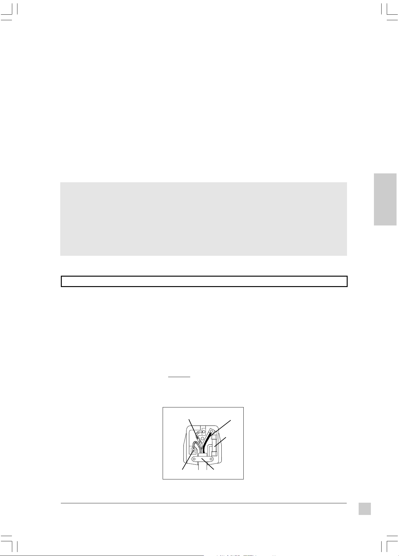
The mains lead on this equipment is
supplied with a moulded plug
incorporating a fuse, the value of which
is indicated on the pin face of the plug.
Should the fuse need to be replaced, an
ASTA or BSI approved BS 1362 fuse of
the same rating must be used.
If the fuse cover is detachable, never
use the plug without the cover. If a
replacement fuse cover is required,
ensure it is of the same colour as that
visible on the pin face of the plug. Fuse
covers are available from your dealer.
DO NOT cut off the mains plug from
this equipment. If the plug fitted is not
suitable for the power points in your
home or the cable is too short to reach
a power point, then obtain an
appropriate safety approved extension
lead or consult your dealer.
Should it be necessary to change the
mains plugs, this must be carried out by
a competent person, preferably a
qualified electrician.
If there is no alternative to cutting off
the mains plug, ensure that you first
remove the fuse then immediately
dispose of the portion remaining, to
avoid a possible shock hazard by
inadvertent connection to the mains
supply.
WARNING: THIS EQUIPMENT
MUST BE EARTHED
The wires in the mains lead are
coloured in accordance with the code
shown in the diagram below:
Green & Yellow to Earth
Blue to Neutral
Brown to Live
Fuse
Cord Clamp
As these colours may not correspond
with the coloured markings identifying
the terminals in your plug, proceed as
follows:
The wire which is coloured Green and
Yellow must be connected to the
terminal in the plug which is marked
with the letter E or by the earth symbol
or coloured Green, or Green and
Yellow.
The wire coloured Blue must be
connected to the terminal marked with
the letter N or coloured either BLUE or
BLACK. The wire coloured BROWN
must be connected to the terminal
marked with the letter L or coloured
either BROWN or RED.
ViewSonic PJ860
Ef-PJ860.p65 01-May-01, 21:021
1
Page 3
WARNING:
This equipment has been tested and found to comply
with the limits of a Class A digital device, pursuant to
Part 15 of the FCC Rules.
These limits are designed to provide reasonable
protection against harmful interference when the
equipment is operated in a commercial environment.
This equipment generates, uses, and can radiate
radio frequency energy, and if not installed and used
in accordance with the user guide, may interfere with
radio communications.
Operation of this equipment in a residential area is
likely to cause interference in which case the user will
be required to correct the interference at his own
expense.
E
N
G
L
I
S
H
Warning Following these instructions could prevent possible injury or death.
If any of the events listed below
occur, switch projector OFF, pull
power plug out of power source,
and contact ViewSonic
Support (see back cover):
• If there is an abnormal smell or
smoke
• If suddenly there is no picture, no
sound, or an abnormal sound
• If water or any other liquid enters
the projector
To prevent possible electric
shock or fire, handle power cord
and power plug with care:
• Do not touch the power cord with
wet hands.
• TO DISCONNECT THE UNIT
FROM THE POWER SOURCE,
GRASP THE POWER PLUG, AND
PULL. DO NOT PULL THE
POWER CORD ITSELF.
• Do not damage the power cord by
pulling, bending, heating, or placing
heavy objects on it.
Important Safety Precautions
To prevent possible electric shock
or fire, keep liquids away from
®
Customer
projector:
• Do not use the projector near water
(such as a shower, sink, etc.).
• Do not put an open container with
liquid on or near the projector (such
as a vase, open beverage container,
etc.).
Do not insert a foreign object into
any part of the projector:
• To prevent electric shock or fire, do
not insert a metal or flammable object
through the ventilation holes, etc.
• If foreign matter enters the projector,
switch it OFF and pull the power plug
out of the power source.
• Prevent small children from inserting
objects into the projector.
Only use recommended power
supply:
• Do not use any power source that has
a voltage other than what this user's
guide specifies. See page 12.
Instructions for FCC compliance:
This equipment complies with the requirements of FCC
(Federal Communication Commission) Class A equipment
provided that the following conditions are met:
1 Video signal cables:
Double shielded coaxial cables (so called FCC shielded
cable) must be used. The outer shield must be connected
to the ground. If normal coaxial cables are used, they must
be enclosed in metal pipes or similar material to reduce the
interference they may cause.
2 Power cord:
A shielded power cord must be used. The outer shield must
be grounded.
3 Video Inputs:
The amplitude of the input signal must not exceed the level
specified in this user's guide.
CAUTION:
To prevent possible eye damage:
•
DO NOT look directly at the laser
light from the aperture at the
front of the Remote Control
Unit. (See page 7.)
•
DO NOT point the laser light at
any person's eyes.
Also, do not look directly into
projector lens when lamp is lit:
• Prevent all people, especially small
children, from looking into the
projector lens when the lamp is lit.
Do not subject projector to
physical shock or place projector
on unstable surface:
• Do not place the projector in a
location where it is likely to be struck
or bumped into.
• Avoid placing the projector on a shelf,
cabinet, etc. that cannot adequately
support its weight, or that is on an
inclined floor.
• When the projector is placed on a
table with casters, set the caster
stoppers to prevent movement.
Caution Following these instructions could prevent personal injury or damage to the projector.
To prevent damage from heat
build-up:
• Clean the air filter after every 100
hours of operation. (See page 16.)
• Do not place the projector in direct
sunlight or near a source of heat like a
furnace, electric heater, etc.
• Do not block ventilation holes (by
placing the projector on its side, or on
a carpet, bedspread etc.)
• Place the projector at least 10 cm
from any wall (allowing space for the
ventilation holes).
2
Ef-PJ860.p65 01-May-01, 21:022
Do not place projector in a moist
or dusty place:
• Do not place the projector in an area
containing steam (from a humidifier,
etc.), dust, or soot (from a stove,
etc).
If projector will not be used for a
long time, pull out power plug and
close lens cover.
Have inside of projector cleaned
at least every two (2) years:
• Contact ViewSonic Customer Service
for information about where to have
the inside cleaned. Never attempt to
open the cabinet to clean the inside of
the projector yourself.
• To clean the lens and cabinet, follow
the instructions on page 16.
Do not place heavy objects on the
projector.
ViewSonic PJ860
Page 4

CONTENTS
For Your Records . . . . . . . . . . . . . . . . . . . . . . . . . . . . . . . . . . . . 1
Electronic Registration . . . . . . . . . . . . . . . . . . . . . . . . . . . . . . . 1
FCC Information . . . . . . . . . . . . . . . . . . . . . . . . . . . . . . . . . . . . 2
Important Safety Precautions . . . . . . . . . . . . . . . . . . . . . . . . . . 2
Getting Started
Package Contents . . . . . . . . . . . . . . . . . . . . . . . . . . . . . . . . . . . 4
Installation . . . . . . . . . . . . . . . . . . . . . . . . . . . . . . . . . . . . . . . . . 4
Inserting Batteries into Remote Control Unit
Connecting Input/Output Devices . . . . . . . . . . . . . . . . . . . . . . . 5
Side Connector Panel
Example of System Setup
Operation
Projecting a Picture. . . . . . . . . . . . . . . . . . . . . . . . . . . . . . . . . . 6
Turning Off the Projector
Positioning the Projector
Setting the Projection Angle
Controls and Indicators. . . . . . . . . . . . . . . . . . . . . . . . . . . . . . . 7
Adjusting the Projected Image . . . . . . . . . . . . . . . . . . . . . . . . . 8
Memory Function
Returning to Factory Default Settings
Freeze Function
Magnify Function
Set Up Menu. . . . . . . . . . . . . . . . . . . . . . . . . . . . . . . . . . . . . . . . 9
Auto Adjustment Function
Input Menu . . . . . . . . . . . . . . . . . . . . . . . . . . . . . . . . . . . . . . . . 10
Image Menu . . . . . . . . . . . . . . . . . . . . . . . . . . . . . . . . . . . . . . . 10
Option Menu . . . . . . . . . . . . . . . . . . . . . . . . . . . . . . . . . . . . . . 11
Technical Information
Specifications . . . . . . . . . . . . . . . . . . . . . . . . . . . . . . . . . . . . . 12
Timing Chart . . . . . . . . . . . . . . . . . . . . . . . . . . . . . . . . . . . . . . 13
Connecting to the RS232 Port . . . . . . . . . . . . . . . . . . . . . . . . . 13
Mouse Emulation
E
N
G
L
I
S
H
ViewSonic PJ860
Ef-PJ860.p65 01-May-01, 21:023
Troubleshooting
On-Screen Warning Messages . . . . . . . . . . . . . . . . . . . . . . . . 14
Problem Solving Chart . . . . . . . . . . . . . . . . . . . . . . . . . . . . . . 14
Control Panel Indicators . . . . . . . . . . . . . . . . . . . . . . . . . . . . . 15
Customer Support . . . . . . . . . . . . . . . . . . . . . . . . . . . . . . . . . . 15
Maintenance
Cleaning Instructions . . . . . . . . . . . . . . . . . . . . . . . . . . . . . . . 16
Cleaning the Air Filter
Cleaning the Lens
Cleaning the Cabinet
Replacing the Lamp Unit . . . . . . . . . . . . . . . . . . . . . . . . . . . . . 16
Warranty . . . . . . . . . . . . . . . . . . . . . . . . . . . . . . . . . . . . . . . . . . 17
3
Page 5

Getting Started
TM
Congratulations on purchasing a ViewSonic PJ860 Office Theater
Save the original box and all packing material for future shipping needs.
Package Contents
•
ViewSonic PJ860 Office Theater
•
Remote Control Unit/Mouse & Laser Pointer
•
2 AA batteries
•
3 AC power cords (U.S., Europe, and China)
•
RGB computer video cable (15-pin mini D-sub
connector)
•
Video/Audio cable (RCA connectors)
E
N
G
L
I
S
H
• S-Video cable
•
Audio (stereo) mini-DIN cable
* IMPORTANT: The supplied INF file assures compatibility with Windows
operating systems, and the ICM file (Image Color Matching) ensures
accurate on-screen colors. When using a computer as the signal source,
ViewSonic® recommends that you install both of these files.
• Insert the supplied CD-ROM into your system, wait for it to auto-start,
select “Monitor Drivers,” and follow the on-screen instructions.
(RCA connectors)
•
PS/2 mouse cable
•
Serial (RS232) mouse/computer-control cable
•
ADB (Macintosh®) mouse cable
•
Macintosh adaptor
•
User’s guide
•
INF and ICM files on CD-ROM*
•
Carrying Case
LCD projector!
Installation
1 Connect signal input cables
With both the PJ860 and the
computer powered OFF, connect
the appropriate video and audio
cables to the computer, VCR, or
other input sources.
Macintosh users:
supplied Macintosh adapter to the
video cable, then to the PJ860.
Connect the
2 Connect power cord
Connect the power cord to a
properly grounded AC outlet, then
to the PJ860.
3 Power-ON projector and all input
devices (computer, VCR, etc.)
• Power-ON the PJ860 projector.
• Power-ON all input devices.
Inserting Batteries into the Remote Control Unit
1 Remove the compartment cover by
sliding it in the direction of the arrow
shown below.
2 Insert the batteries (Alkaline type)
with the polarities (+,-) facing the
direction shown below.
3 Replace the compartment cover.
3 (continued)
When a PC is one of the input
devices (not for Macintosh):
(1) Install INF and ICM files
See instructions in the
"IMPORTANT" note above.
(2) Set signal timing of
graphics card
Set the graphics card(s) to
800 x 600@75 Hz
(resolution and refresh
rate).
4 Install batteries into
Remote Control Unit
See instructions below.
CAUTION:
• Only use AA (LRG) type of batteries.
• To prevent leakage that may damage
the unit, do not combine old and new
batteries.
• When inserting batteries, be careful
to insert them according to the
correct polarities (+,-).
• If not using the Remote Control Unit
for an extended period of time,
remove the batteries.
• Do not place the Remote Control Unit
on any wet surface or close to the
cooling fan of the projector.
To be best prepared for any future
customer service needs:
•
Write the serial number (see the
bottom of the projector) in
Records"
•
Register the warranty of your projector
on the Internet at:
http://www.viewsonic.com
on page 1 of this guide.
"For your
4
E1-PJ860.p65 01-May-01, 21:164
Getting Started
ViewSonic PJ860
Page 6
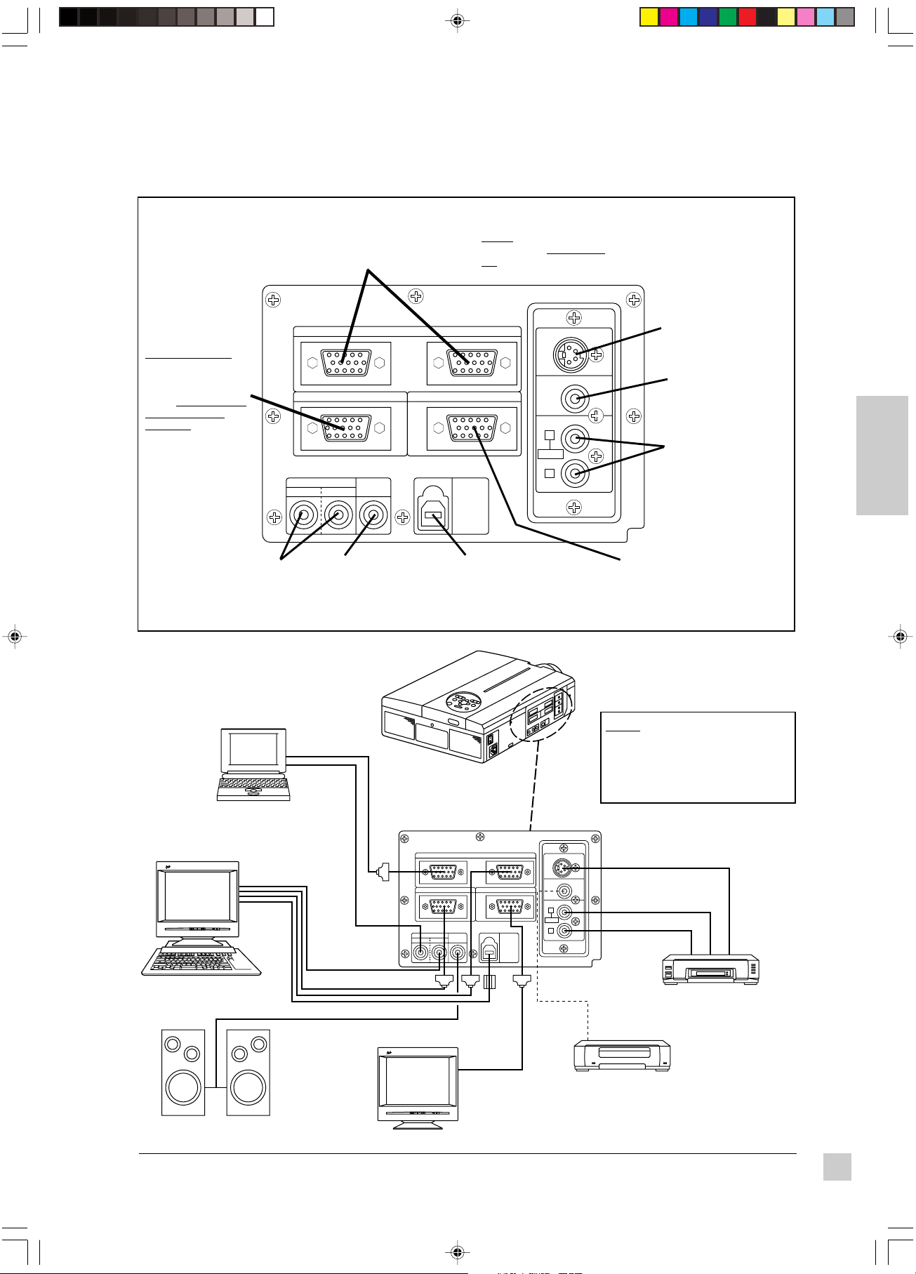
Connecting Input/Output Devices
Side Connector Panel
"RGB1" & "RGB2"
RGB input ports (2)
D-sub 15 pin type
(to video output of computers)
NOTE: RGB1 supports
Plug & Play; RGB2 does
not support Plug & Play.
CONTROL port
(RS232C type) for
mouse emulation
(PS2 PC mouse,
serial PC mouse, or
Macintosh® mouse);
or for controlling the
CONTROL RGB OUT
projector from a
computer. See page
13 for more information.
AUDIO input ports (2)
stereo mini type (left port =
stereo audio with RGB1; right
port = stereo audio with RGB2)
AUDIO IN
12
AUDIO
OUT
AUDIO output port
stereo mini type
(to audio amplifying
equipment)
Example of System Setup
RGB IN12
USB
S-VIDEO IN
VIDEO IN
AUDIO IN
L
MONO
R
USB input port
(Upstream) The mouse
cursor can be controlled by
connecting the PJ860
projector to a computer.
S-VIDEO input port
Mini DIN 4 pin type
(used with S-VIDEO
output equipment)
VIDEO input port
RCA type (used with
Composite VIDEO
output equipment)
AUDIO input ports
RCA type, Left/Right
(used with either SVIDEO or Composite
VIDEO outputs)
RGB output port
D-sub 15 pin
(to video input of CRT
Display)
E
N
G
L
I
S
H
Laptop Computer
ViewSonic
1 2
Desktop Computer
Audio amplifying equipment
ViewSonic
1 2
PJ860 Projector
RGB IN12
CONTROL RGB OUT
AUDIO IN
AUDIO
OUT
12
CRT Display
NOTE: Two computers can be
connected (using RGB1 and
RGB2). Only one VCR should be
connected (using either the
Composite video or S-video
output port).
S-VIDEO IN
VIDEO IN
AUDIO IN
L
MONO
R
USB
VCR with S-VHS out
VCR
ViewSonic PJ860
E1-PJ860.p65 01-May-01, 21:165
Getting Started
5
Page 7

b
a
Operation
Projecting a Picture
1 Power ON the projector. Set the MAIN POWER switch to ON (located
on the side Connector Panel). The ON indicator lights orange.
2 Press the STANDBY/ON button on the Projector Control Panel or on
the Remote Control Unit. (See page 7.)
The ON indicator blinks green during warm-up and stays green
when projector is ready for use.
NOTE: The power can not be turned on if the STANDBY/ON button
is pressed within 60 seconds after the power is turned off.
3 Remove the lens cap.
4 Position the projector the desired distance from the projection
E
N
G
L
I
S
H
screen, then set the projection angle by positioning the foot
adjusters. (See
Angle
below.)
5 Power ON all connected input devices. (See page 5.)
6 Select the signal source: press the INPUT button on the projector or
one of the INPUT buttons (VIDEO/RGB) on the Remote Control Unit.
(See page 7.)
NOTE: To switch between RGB1 and RGB2, use the INPUT
menu (see page 10).
7 Using buttons on the Remote Control Unit or the control panel on top
of the projector, adjust the picture size with the ZOOM button, then
adjust the focus using the FOCUS button.
Positioning the Projector
and
Setting the Projection
Turning Off the Projector
1 Press STANDBY/ON button (on Control
Panel or Remote Control Unit) for one (1)
second. The ON indicator blinks orange
and the projector lamp turns off.
CAUTION: Always press the
STANDBY/ON button before turning
OFF the MAIN POWER. This allows the
fan to cool down the projector.
2 Wait until the fan stops (about one minute
after pressing STANDBY/ON button).
3 Power OFF the projector. Set the MAIN
POWER switch to OFF.
4 Place the lens cap over the lens.
Positioning the Projector
The projector must be horizontal to get a distortion-free picture. Place the projector on a table-top or other flat
surface. Use the chart below to determine the placement of the projection screen.
neercS
eziS
)sehcni(
0455371
06584112
084111512
0014411913
0216711323
0510222824
0021926836
muminiMmumixaM
"a"ecnatsiD
)sehcni(
"b"ecnatsiD
)sehcni(
---------------
Top View
Screen
CAUTION To prevent a build-up of heat
that can damage the projector:
• Be especially careful not to block
ventilation holes when installing the
projector.
• Only use this projector in the horizontal
position (see Side View shown above).
Side View
a = distance from projector
to screen
b = distance from center of
lens to bottom of screen
(a, b: +/- 10%)
Setting the Projection Angle
1 While firmly grasping the front of the projector with both hands, use
your index finger to push --and hold-- the Adjuster Buttons (located on
the sides of the projector).
2 While pressing the Adjuster Buttons, tilt the front of the projector up in
order to adjust the viewing angle. Then (while still grasping the
projector) release the Adjuster Buttons, securely locking the Front
Foot Adjusters.
3 To make fine adjustments, turn the base of the Front Adjusters.
Front View
Front Adjusters
CAUTION
• To prevent possible injury or damage to the projector, make sure
you are holding onto the projector securely before you unlock the
foot adjusters.
• Securely lock the Front Adjusters.
• Do not use unnecessary force when you move the foot adjusters.
6
E2a-PJ860.p65 01-May-01, 21:226
Operation
Side View
You can make vertical adjustments
(0 to 9 degrees) using the Front
Foot Adjusters.
ViewSonic PJ860
Page 8

Controls and Indicators
Projector Control Panel
MUTE button silences
audio output temporarily
LAMP indicator
becomes lit when
lamp cannot light
ON indicator
blinks in Standby
mode; remains lit
in Operation mode
TEMP indicator
becomes lit when
temperature inside
projector is too high
RESET button
resets selected
menu option to
factory setting
STANDBY /ON button
powers ON/OFF button.
OFF activates Standby
Mode
ZOOM button
adjusts the size of the
projected picture.
FOCUS button
adjusts the sharpness
of the projected picture.
INPUT button
selects input source:
RGB2 VIDEO
RGB1
MENU buttons used
to display on-screen
menus and to adjust
the selected option.
FREEZE displays a
still picture, stopping
audio and moving
video image
MAGNIFY buttons
magnify part of
projected picture
OFF button turns OFF the
MAGNIFY function (+/-)
BLANK button displays
blank screen (white, blue,
or black). See page 10.
FOCUS button
adjusts the sharpness
of the projected picture.
Remote Control Unit
VIDEO
STANDBY/ON
MENU
MAGNIFY
P in P MUTE
FOCUS ZOOM
LASER
POSITION
RESET
FREEZE
VOLUME
OFF
AUTOBLANK TIMER
RGB
VIDEO button and RGB button
These two buttons are used to
select either Video or RGB
(computer) as the input source.
NOTE: Same function as INPUT
button on Projector Control Panel
LASER button toggles laser-pointer
On/Off.
See CAUTION below.
POSITION button After
pressing this button, move
the DISK PAD (up/down,
left/right) to move screen
image (only for RGB signal)
DISK PAD
•
When a menu screen is
displayed, use DISK PAD to
select or adjust a menu item.
•
When menu is
mouse cables are connected, the
DISK PAD functions as a mouse.
Press center of DISKPAD for leftclick mouse function.
•
After pressing POSITION button,
DISK PAD moves entire screen
image.
RESET / "RIGHT " MOUSE button
(two functions)
•
RESET button: when a menu is
displayed, returns selected
menu option to factory setting.
•
"RIGHT" MOUSE button: when
no menu is displayed
VOLUME buttons adjust loudness
of audio output
MUTE button silences
audio output temporarily
TIMER button activates on-screen
countdown timer
ZOOM buttons are used to adjust
the size of the screen image
AUTO button automatically adjusts
Vertical Position, Horizontal
Position, Horizontal Phase, and
Horizontal Size.
not displayed, and
E
N
G
L
I
S
H
Remote control
sensor (rear)
Lens
Lens cap
ViewSonic PJ860
Cooling fan
(intake)
Speakers
Handle
Cooling fan
(exhaust)
Back View of Remote Control Unit
Battery
Compartment
Laser
Aperture
CAUTION
To prevent possible eye damage:
•
DO NOT look directly at the laser light
emitted from the Laser Aperture of the
Remote Control Unit (see above).
•
DO NOT point the laser light at any
person's eyes.
Operation
7
E2a-PJ860.p65 01-May-01, 21:227
Page 9

Adjusting the Projected Image
1 Display the list of menus. Press any one of the four MENU
buttons on the Projector Control Panel or the MENU ON/OFF
button on the Remote Control Unit. The names of the four
menus (SETUP, INPUT, IMAGE, OPTION) will display. (See
pages 8-10.)
2 Select the menu.To select one of the four menus, press the
left or right MENU buttons on the Projector Control Panel or
the DISK PAD on the Remote Control Unit. The name of the
selected menu is highlighted in green.
3 Select the menu option.To select a menu option you want
to adjust, use the MENU buttons on the Projector Control
Panel or use the DISK PAD on the Remote Control Unit. The
selected adjustment option is highlighted in green.
Returning to Factory Default Settings
E
N
G
L
I
S
H
To return all the controls in a given menu to factory settings:
1 Select the menu (follow step 2 above).
2 Press the RESET button (on the projector control panel or
Remote Control Unit), and select DEFAULT.
If you change your mind, select CANCEL.
NOTE: To return a single control (Volume, Brightness, etc.) to
the factory setting, select only that menu option, and press
RESET. If you change your mind, select CANCEL.
Memory Function
Whenever you power OFF the projector, all picture
adjustments made for each input device (VIDEO, RGB1, and
RGB2) will be saved separately.
Freeze Function
This function displays a still picture, freezing a moving video
image (similar to the "pause" function of a VCR).
1 Press the FREEZE button on the Remote Control Unit.
2 To release the Freeze function, press the FREEZE button
again.
Magnify Function
This function allows you to magnify a portion of the
projected picture.
1 To activate the Magnify function: Press the MAGNIFY button
on the Remote Control Unit. The center of the projected
picture will double in size.
2 To change magnification: Press the [+] button to increase
magnification (maximum, 4 times). Press the [-] button to
decrease magnification (minimum, about 1.1 times)
3 To shift the magnified display area: Press the POSITION ON
button, then press the DISK PAD up, down, left, or right.
The magnified display area shifts accordingly.
4 To return to a normal display: Press the OFF button (below
the FREEZE button).
NOTE: FREEZE and MAGNIFY can
not be used simultaneously.
NOTE: The Magnify function is released when an INPUT
SELECT button (on projector or Remote Control Unit) or
when the timing mode (resolution or refresh rate) of a
personal computer is changed while an image is displayed.
8
E2a-PJ860.p65 01-May-01, 21:228
Operation
ViewSonic PJ860
Page 10

SET UP Menu
The SET UP Menu allows you to adjust the picture for each input source separately: RGB1, RGB2, and VIDEO
(Composite Video or S-Video).
NOTE: Before using the SET UP Menu, use the INPUT Menu to select one of the input sources, then repeat these
steps for each of the other input sources (see next page). Two computers can be connected (using RGB1 and
RGB2), and one video source should be connected (using either the Composite video or S-video input port).
See page 5 for information about the input ports.
snoitpOuneMPUTESstnemtsujdA
EMULOVesaercnI--esaerceD
)SSENTHGIRB(THGIRBrethgirB--rekraD
TSARTNOCrehgiH--rewoL
ylnotupnilangisOEDIVroF
SSENPRAHSreprahS--retfoS
)NOITARUTAS(ROLOCrehgiH--rewoL
TNITneerG--deR
ylnotupnilangisBGRroF
TISOPV
)NOITISOPLACITREV(
)lortnoc
TISOPH
LATNOZIROH(
)NOITISOP
ESAHPH
)ESAHPLATNOZIROH(
EZISH
)EZISLATNOZIROH(
RLABROLOC
)DERECNALABROLOC(
BLABROLOC
ECNALABROLOC(
)EULB
* "Horizontal noise" appears as horizontal lines on the screen image when
Horizontal Phase is not adjusted; when adjusted properly, text characters
appear sharp.
nwodropuerutcipsevoM
citamotua--OTUAesuro(
thgirrotfelerutcipsevoM
)OTUAesuro(
*esioNlatnoziroHsetanimilE
)OTUAesuro(
ezislatnozirohsworran/snediW
)OTUAesuro(erutcipfo
rekraD>----<rethgiL:deR
rekraD>----<rethgiL:eulB
VIDEO signal input
RGB signal input
E
N
G
L
I
S
H
NOTE:
• TINT cannot be adjusted with PAL/SECAM video signal
input.
• TINT, COLOR, and SHARPNESS cannot be adjusted with
RGB signal input.
• V. POSIT, H. POSIT, H. PHASE, and H. SIZE cannot be
adjusted with VIDEO signal input.
AUTO Adjustment function
The AUTO Adjustment function automatically adjusts 4 controls: V. POSIT
(Vertical Position), H. POSIT (Horizontal Position), H. PHASE (Horizontal
Phase), and H. SIZE (Horizontal Size).
NOTE -- Auto Adjust:
• May require several seconds to execute
• May not operate correctly with some projected images
• May cause parts of the projected image to be slightly dark in some cases
• Can not execute when the FREEZE or MAGNIFY function is in use, or
when the initial on-screen message is "NO INPUT IS DETECTED" or
"SYNC IS OUT OF RANGE."
ViewSonic PJ860
Operation
9
E2b-PJ860.p65 01-May-01, 21:249
Page 11

INPUT Menu
The INPUT Menu allows you to select from three possible input sources (RGB1, RGB2, and VIDEO). For
VIDEO, the AUTO option will work for most circumstances (N-PAL is not suppported).
TUPNI
snoitpO
BGR
)2&1(
OEDIV
noitpircseDtnemtsujdA
:stupniBGRgniwollofehtsyalpsiD
ycneuqerfcnyslatnoziroh:Hf
ycneuqerfnyslacitrev:Vf
)oediV-SrooedivetisopmoC
rehtie(tropOEDIVmorflangisstceleS
RGB options
elbatsnusineercsehtnehW:ETON
ehttceles,)egamignillorrorolocon(
.langistupniehtsehctamtahtedom
E
N
G
L
I
S
H
NOTE: RGB1 is compatible with Plug
and Play (DDC1TM and DDC2BTM);
RGB2 is not.
VIDEO options
IMAGE Menu
The IMAGE Menu allows you to select the KEYSTONE, MIRROR, BLANK, START UP and P in P options.
EGAMI
uneM
snoitpO
ENOTSYEK
yllacitrev
noitpircseDtnemtsujdA
tanoitrotsidenotsyeksecudeR
erutcipfo--mottobro--pot
gnisiarybdesuac)epahsdiozepart(
ehtgnisurotcejorpfotnorfeht
.)6egapees(sretsujda
ro/dnayllatnoziroherutcipstrevnI
10
Operation
yrotcafotsnruteRLAMRON
sgnittes
RORRIM
KNALB
.detceted
PUTRATS
.pu
PniP
.egami
erutcipstrevnITREVNI:H
yllatnoziroh
erutcipstrevnITREVNI:V
yllacitrev
erutcipstrevnITREVNI:V&H
dnayllatnoziroh
yllacitrev
,etihw(rolocdnuorgkcabstceleS
neercSknalBehtrof)kcalbro,eulb
yalpsidlliwneercsknalbehT.erutaef
tupnidetcelesehtsiOEDIVnehw
silangistupnioedivondnaecruos
NOTE: The source of the "large picture" of the P in P
ehttceles-ed/tcelesotuoyswollA
busehtfonoitisopehtstceleS
neercserutciP-ni-erutciP)llams(
(picture in picture) image is the RGB (computer) signal
and the source of the "small picture" is the VIDEO signal.
-tratstaneercsemoclewcinoSweiV
With P in P activated, the audio source defaults to the
audio from the VIDEO source. To switch to the RGB
(computer) audio source, push one of the Volume buttons.
No picture is displayed when either no signal is detected
or when the signal is out of the signal range.
ViewSonic PJ860
E2b-PJ860.p65 01-May-01, 21:2410
Page 12

OPT. (OPTION) Menu
The OPT. Menu allows you to adjust the Communication Function* (COM. SPEED and COM. BITS), enabling
you to control the projector from a computer. The OPT. Menu also allows you to set the TIMER, select the
LANGUAGE for all on-screen displays, activate AUTO OFF and START UP.
.TPO
)NOITPO(
uneM
snoitpO
.MOC
DEEPS
-INUMMOC(
)NOITAC
:tamrof
STIB.MOC
REMIT
EGAUGNAL
FFOOTUA
GNOCNYS
tibpotS1
tibpotS1
).rotcejorp
.)setunim99
.0otsetunim
.ffo/noerutaef
tnemtsujdA
noitpircseD
fodeepsatadstceleS
rofdesU(.00291,0069
.erutcipdetcejorpeht
nitistupdna--rotcejorp
aretfa--edoMybdnatS
,0084,0042,0021:noissimsnart
).rotcejorpfolortnocretupmoc
noissimsnartatadstceleS
,ytiraPoN,stibatad7...1N7
,ytiraPoN,stibatad8...1N8
folortnocretupmocrofdesU(
99otpu(remitnwodtnuocA
etavitcanacuoy)setunim
emitehT.dedeenrevenehw
fomottobtasyalpsidgniniamer
weiV-nOfoegaugnalstceleS
siaçnarF,hsilgnE:sunem
,)namreG(hcstueD,)hcnerF(
onailatI,)hsinapS(loñapsE
,)naigewroN(ksroN,)nailatI(
.esenapaJ,)hctuD(sdnalredeN
ehtffostuhsyllacitamotuA
ontahtemitfodoirepdeificeps
otpu(detcetedsiecruostupni
tes,FFOOTUAelbasidoT
neerGnocnySehtselggoT
IMPORTANT: If AUTO OFF is activated and shuts off the
projector lamp, wait at least one (1) minute. Then press--and
briefly hold--the STANDBY/ON button. The lamp will turn back
on.
* NOTE: Computer control of the projector (communication
function) is an advanced feature that requires specialized
software not included with the PJ860. To develop this software
you will need various control codes and other supplementary
information available from ViewSonic Customer Support. (See
page 15.)
E
N
G
L
I
S
H
ViewSonic PJ860
E2b-PJ860.p65 01-May-01, 21:2411
Operation
11
Page 13

Technical Information
Specifications
LCD Type 1.3" Polysilicon (x3) Stripe Pixel 800 x 600 TFT Active Matrix
Pixels 1,440,000 (800 dots x 600 lines x 3 colors)
Lens Type Power Focus, Power Zoom (1-1.3X) F1.7 ~ 2.3 (f = 49 - 64 mm)
Display Image Size 30" - 300" (76.2mm x 7620mm)
Projection Distance 1.1m - 11m
Brightness 1700 ANSI Lumens (typical)*, 1360 ANSI Lumens (minimum)
Contrast Ratio 100:1 (typical - ANSI method), 200:1 (typical - non-ANSI method)
Aspect Ratio 4:3
Lamp 190 W Ultra High Pressure compact
Lamp Life 1500 hours (shutdown)
Audio Power 2 W (1 W + 1 W) 10%THD
E
N
G
L
I
S
H
Input Signal RGB Analog 75 ohms, 0.7 Vp-p X2 H/V Separated, Composite (TTL)
Video NTSC 3.58 / PAL-N, PAL-M / SECAM S-Video
Luminance signal 0.7 Vp-p, 75 ohms termination
Chrominance signal 0.29 Vp-p (NTSC), 0.30 Vp-p (PAL), 75 ohms
termination
Frequency f
Compatibility PC PC compatible (up to 1024 x 768 compressed)
Macintosh
®
** Power Macintosh® (up to 1024 x 768 compressed)
: 15.75/15.63, 25-60 kHz fv: 56-85 Hz
h
Video NTSC 3,58 / PAL-N, PAL-M / SECAM S-Video
Maximum 1024 x 768 @ 75 Hz (Compressed)
Recommended 800 x 600 @ 60 Hz
Resolutions
Input Ports RGB 15 pin mini D-sub (x2)
Video RCA (x1)
S-Video Mini DIN 4-pin (x1)
Audio RCA jack (L/R) for Video, Stereo Mini (x2) for RGB
Output Ports RGB 15 pin mini D-sub (x1)
Audio Stereo Mini (x1) for Audio-out
Power Voltage AC 100-120/220-240 50 / 60 Hz (Automatic), 3 Wire Grounded
Consumption 370 Watts
User Controls Physical/projector Standby On/Off, Menu (Left, Right, Up, Down), Input, Reset, Mute
Video Input Bandwidth 82 MHz
Operating Temperature 32°F to 95°F (0°C to 35°C)
Conditions Humidity 10% to 85% (no condensation)
Optimum Temperature 59°F to 82°F (15°C to 28°C)
Installation Humidity 40% to 75% (no condensation)
Environment
Storage Temperature -4°F to +140°F (-20°C to +60°C)
Conditions Humidity 10% to 85% (no condensation)
Dimensions Physical 292 mm (W) x 124 mm (H) x 395 mm (D)
11.4" (W) x 4.9" (H) x 15.5" (D)
Packing 385 mm (W) x 370 mm (H) x 532 mm (D)
15.1" (W) x 14.5" (H) x 20.9" (D)
Weight (typical) Net 5.9 kg (13.0 lb)
Gross 11.8 kg (26.0 lb)
Regulations UL, FCC-A, cUL, CE, CB Report, TÜV/GS, EMC report
Power Savings "On" Green 370 W
"Stand By" Amber 11 W
* Brightness may vary with lamp age and environmental conditions.
** Macintosh computers require a Macintosh adaptor (supplied with the PJ860 projector).
All products and trademarks are brand names of their respective companies. Specifications are subject to change without notice.
12
E3-PJ860.p65 04-May-01, 10:1312
Technical Information
ViewSonic PJ860
Page 14

Timing Chart
1 2 3 4
6 7 8 9
5
D-sub 9pin
6 5
34
2 1
Mini Din 6pin
The following table lists the maximum refresh rates that the ViewSonic PJ860 will operate at a number of standard
resolutions (timing presets). While the projector is capable of this level of performance, not all video cards are
capable of operating at these signal timings. See your graphics card's user guide to ensure compatibility.
sgnimiTlangiS/retupmoC
noituloseR
VxH
tupnI
lacitreV
ycneuqerF
)etaRhserfeR(
)zH(
latnoziroH
ycneuqerF
)zHk(
yrtsudnIzH65@004x046004x0464.658.42
1-AGVASEVzH58@053x046053x0461.589.73-/2-AGVASEVzH58@004x046004x0461.589.73-/-
27ASEVzH58@004x0084x0460.589.73-/-
3-AGVASEVzH06@084x046084x0469.955.13-/-
®
caM
"31zH76@084x046084x0467.660.53-/-
ASEV3-AGVzH37@084x046084x0468.279.73-/-
3-AGVASEVzH57@084x046084x0460.575.73-/-
3-AGVASEVzH58@084x046084x0460.583.34-/AGVSASEV06x008zH65@0006x0083.652.53+/+
AGVSASEV006x008zH06@006x0083.069.73+/+
AGVSASEV006x008zH27@006x0082.271.84+/+
AGVSASEVzH57@006x008006x0080.579.64-/AGVSASEVzH58@006x008006x0081.587.35-/-
zH57@426x238"61caM
)laitrap(
zH06@867x4201AGXASEV
zH07@867x4201AGXASEV
zH57@867x4201AGXASEV
)desserpmoc(
)desserpmoc(
)desserpmoc(
426x2386.477.94+/+
867x42010.064.84-/867x42011.075.65-/867x42010.570.06-/-
foytiraloP
gnizinorhcnyS
V/HlangiS
E
N
G
L
I
S
H
CAUTION: Some input sources may not display properly if they are not compatible with the
projector. Some input sources may not display in full size, as shown in Output Resolutions.
Connecting to the RS232 Port
The RS232C Port has two possible uses:
1 Mouse Emulation This allows you to use a mouse with one computer at a time, by toggling between one
computer connected to RGB1 and another computer connected to RGB2.
NOTE: Depending on which type of mouse you will be using (PS/2, ADB, or Serial) you must use the appropriate connector. (See diagrams
below.)
2 Computer Control Port This is only used for special applications in which a computer controls the projector
(instead of the projector's control buttons or Remote Control Unit).
NOTE: To use this feature you must first develop customized software using various control codes. To find out how to access this supplementary
information, contact ViewSonic Customer Support. (See page 15.)
Mouse Emulation
1 With both the projector and the computer powered OFF,
connect the projector and the mouse terminal of the
computer using the appropriate cable. (See diagrams to
the right.)
2 Disconnect the existing mouse.
3 Power ON the projector, then power ON the computer.
NOTE: If mouse emulation will not start, reset the
computer and/or check the mouse driver.
(a) PS/2 mouse
connector
(c) Serial mouse
connector
(b) ADB (Macintosh)
mouse connector
Mini Din 4pin
34
2 1
NOTE:
Depending on which type of mouse you
will be using (PS/2, ADB, or Serial) you
must use the appropriate connector.
ViewSonic PJ860
E3-PJ860.p65 01-May-01, 21:3513
Technical Information
13
Page 15

Troubleshooting
On-Screen Warning Messages
egasseMweiVnO noitcAdednemmoceR
"PMALEHTEGNAHC"
"NOSREP
"NOSREP
E
N
G
L
I
S
H
Problem Solving Chart (Check before contacting Customer Support)
kradsierutciP
derrulbsierutciP
ECNANETNIAMALLAC"
"PMALEHTEGNAHC"
ECNANETNIAMALLAC"
NRUTLLIWREWOPEHT"
".RH02RETFAFFO
PMALEHTEGNAHC
)egassemgniknilB(
DETCETEDSITUPNION .secivedtupnillaotsnoitcennocelbacllakcehC.detcetedsitupnilangisoN
EGNARFOTUOSICNYS nihtiwsi)ycneuqerflacitreVdnalatnoziroH(langistupniehterusekamotkcehC
motpmySesuaCelbissoPnoitcAdednemmoceR
I NOtonsihctiwsrewoPniaM
I detcennocsidsidrocrewoP
I despaletonevahsdnoces06
nodenrutebtonnacrewoP
I tohootsirotcejorpehtedisnI
I yltcerroctestonsiecruostupnI
rolocdnaelaperasroloC
I fotuosiESAHPHrosucoF
I ylreporpgninoitcnuftonsipmaL
*dertilsirotacidnIPMAL
*dertilsirotacidnIPMET I gnitaehrevolanretnI
I tonerarotcejorpotsnoitcennoC
I tonerarotcejorpotsnoitcennoC
I muminimottessiemuloV
I edometuMnisirotcejorP
I tonerarotcejorpotsnoitcennoC
I muminimottessissenthgirB
I dehcattasipacsneL
I rolocdnaytisnedroloC
I toneratsartnoCdnassenthgirB
I dneehtgniraensipmalehT
dnuosroerutcipoN
dnuostuohtiwerutciP
erutciptuohtiwdnuoS
roopsignihctam
.61egap
.61egap
ffodenrutsawrewopehtecnis
tcerroc
tcerroc
tcerroc
yltcerroctoneragnihctam
detsujda
yltcerrocdetsujda
efilecivresstifo
tnemtsujda
I NOhctiwSrewoPniaMnruT
I tekcosCAnaotnidrocrewoptresnI
I tatiaw,ffodenrutsirewopretfA
I ehttahterusekamotkcehC
I retlifriaehtnaelC
I tnemnorivnegnitarepotahtyfireV
I gnisuecruostupnitcerroctceleS
I detcennocera)s(elbacyfireV
I detcennocera)s(elbacyfireV
I ,lenaPlortnoCrotcejorPehtmorF
I pacsnelehtevomeR
I detcennocera)s(elbacyfireV
I etomeRrorotcejorprehtienO
I oedivehttsujdA
I dna)ssenthgirB(THGIRBtsujdA
I tinupmalehtecalpeR
I ESAHPHrosucoftsujdA
I 02tiaw,FFOhctiwSrewoPnruT
I ehttahterusekameesotkcehC
I retlifriaehtnaelC
I tnemnorivnegnitarepotahtyfireV
.noosdecalperebdluohstinupmalehT ffonrutlliwrewopesufosruoh002retfA
eeS.emitpmalehtteserdnatinupmalehtecalpertonoduoyfiyllacitamotua
®
cinoSweiVllaC.dednemmocersitinupmalehtgnicalpeR
.setunim01retfaffonrutlliwrewopehT.wontinupmalehtecalpeR
.31egapeeS.rotcejorpehtybdetroppusegnareht
niaganorewop
yltcerroc
yltcerroc
yltcerroc
TSARTNOC
gninruterofebsdnoces06tsael
dekcolbtoneraselohnoitalitnev
C°53rednusirotcejorpfo
rorotcejorpnonottubTUPNI
UNEMehthtiwTHGIRBtceles
,nottubUNEMsserp,tinUlortnoC
.esaercnidna,THGIRBtceles
dekcolbtoneraselohnoitalitnev
sselroC°53rednusirotcejorpfo
otecivreSremotsuC
02retfayllacitamotuaffonrutlliwrewoP.)A30-091-ULR(tinupmalwenaredro
eeS.emitpmalehtteserdnatinupmalehtecalpertonoduoyfiesufosruoh
egaP
.oN
7,6
TUPNIneercs-noehtgnisseccayb
tinUlortnoCetomeRehthtiwunem
nottub]>[ehtsserpnehtdnanottub
niagaNOrewopnrutneht;setunim
01,7
5
5
7
7,5
7,6
9,5
9
9
7
6
7,6
14
E4-PJ860.p65 01-May-01, 22:0314
Troubleshooting
ViewSonic PJ860
Page 16

Control Panel Indicators
rotacidnINOrotacidnIPMALrotacidnIPMETgninaeMnoitcAdednemmoceR
egnarosthgiLffosnruTffosnruTedomybdnatS---------------------
neergsknilBffosnruTffosnruTpugnimrawelihW---------------------
neergsthgiLffosnruTffosnruTnoitarepolamrongniruD---------------------
egnarosknilBffosnruTffosnruTnwodgniloocelihW---------------------
dersthgiLdersthgiLffosnruTthgiltonnacpmaL
dersthgiLdersknilBffosnruT
dersthgiLffosnruTffosnruT
dersknilBdersknilBdersknilB
nepo
ylreporp
sruoh
Customer Support
Most of your questions can be answered as follows:
1 For the nearest ViewSonic authorized service provider, look up the
ViewSonic Web site for your region or country.
2 For other assistance contact your reseller, or ask your reseller to
refer you to a service center.
3 For additional assistance see the contact information listed below.
NOTE: You will be asked to provide a serial number (on the back
of the product).
teldnarotcejorpFFOrewoP
.setunim02rofnwodloocti
,tilllitssirotacidnIPMALfI
.evitcefedebyampmaleht
.tinUpmaLehtecalpeR
ylreporptonsipmaL
siroodpmalro,dellatsni
gnikrowtonsinafgnilooC
.troppuS
pmalfoemitevitalumuC
005,1dedeecxesahesu
.)61egap
deloocsahpmalehtretfA
ehttresni,).nim54(nwod
-erdnaylerucestinUpmaL
.revocpmalehthcatta
remotsuCcinoSweiVtcatnoC
E
dnatinUpmaLehtecalpeR
ees(emiTpmaLehtteser
N
G
L
I
S
H
Country/Region Web site T = Telephone Email
F = FAX
United States viewsonic.com/ T: (800) 688-6688 service.us@
support F: (909) 468-1202 viewsonic.com
Canada viewsonic.com/ T: (800) 688-6688 service.ca@
United Kingdom viewsoniceurope.com T: 0800 833 648 service.eu@
Europe, Middle viewsoniceurope.com Contact your service.eu@
East, Baltic reseller viewsoniceurope.com
countries, and
North Africa
Australia and New viewsonic.com.au T: +61 2 9929 3955 service.au@
Zealand F: +61 2 9929 8393 viewsonic.com
Singapore/India and viewsonic.com.sg T: 65 273 4018 service.sg@
Southeast Asia F: 65 273 1566 viewsonic.com
Other Asia/Pacific viewsonic.com.tw T: 886 2 2246 3456 service.ap@
countries and F: 886 2 8242 3668 viewsonic.com
Indian Peninsula
South Africa viewsonic.com/asia T: 886 2 2246 3456 service.ap@
support F: (909) 468-1202 viewsonic.com
F: (01293) 643910 viewsoniceurope.com
F: 886 2 8242 3668 viewsonic.com
ViewSonic PJ860
E4-PJ860.p65 01-May-01, 22:0315
Troubleshooting
15
Page 17

Maintenance
Cleaning Instructions
To ensure that the projector functions properly, follow the recommended cleaning instructions below.
Cleaning the Air Filter
IMPORTANT: Clean the air filter about every 100 hours.
1 Turn OFF the Main Power switch of the projector and disconnect
the power cord from the wall outlet.
2 Remove the Front Filter Cover (see diagram to the right).
3 Remove the air filter from the Front Filter Cover (as shown in the
illustration to the right) and use a vacuum cleaner to clean the
filter.
4 Re-install the air filter, then the Front Filter Cover.
E
N
G
L
I
S
H
NOTE: If sufficient dust, etc. collects in the air filter, a protection circuit in the projector
will automatically turn off the power. To prevent this from occurring, make sure you clean
the air filter every 100 hours.
Cleaning the Lens
Front Filter
Cover
• To clean the lens, use a camera lens cleaning tissue or a
camel hair brush.
• Be careful not to scratch the lens with a sharp or hard object.
CAUTION: Never use any ammonia
or alcohol based cleaner on the lens.
Cleaning the Cabinet
• Use a soft, dry, lint-free cloth to wipe dust, etc. from the cabinet.
• If this is insufficient, use a soft, lint-free cloth moistened with a
mild detergent diluted with water. Then wipe the surface with a
soft, dry, lint-free cloth.
CAUTION: Never use any
ammonia or alcohol-based
cleaner to clean the cabinet.
Replacing the Lamp Unit
To order a new lamp unit (Part No. RLU-190-03A) contact ViewSonic® Customer Support.
1 Make sure the Main Power switch is OFF, then
disconnect the power cord from the wall outlet. If the
projector has recently been turned on, wait at least
45 minutes for the lamp to cool down.
2 Carefully place the projector onto a flat surface
covered with soft material (like a towel). Then loosen
the Lamp Cover screw and remove the Lamp Cover
(as shown to the right).
3 Loosen the two (2) lamp-unit screws, grasp the
Lamp Unit Handle, and gently pull the lamp unit out
of the projector.
4 Carefully insert the new lamp unit into the projector
and tighten the lamp-unit screws.
5 Re-install the Lamp Cover and tighten the Lamp
Cover screw securely.
Power-on the projector.
6 Reset the lamp time (within 10 minutes)
• Press RESET (on projector) or TIMER (on Remote
Control Unit)
and hold for three (3) seconds
• Press RESET (on projector) or MENU ON (on
Remote Control Unit)
• Select "0" on the screen using MENU [<] (on
projector) or DISKPAD (on Remote Conrol Unit)
Lamp
Cover
Lamp Unit
Handle
Screws
Replace the lamp unit if:
• the picture is dark
• "CHANGE THE LAMP" is
displayed
• the lamp indicator on the
projector remains lit red.
(See page 14.)
CAUTION:
HANDLE THE LAMP UNIT
CAREFULLY. Dropping
the unit could cause the
lamp to explode.
Reflector
Front
Glass
Lamp Unit
16
E4-PJ860.p65 01-May-01, 22:0316
Maintenance
ViewSonic PJ860
Page 18

LIMITED WARRANTY
VIEWSONIC
What the warranty covers:
ViewSonic
proves to be defective in material or workmanship during the warranty period, ViewSonic will, at its sole option, repair or replace
the product with a like product. Replacement product or parts may include remanufactured or refurbished parts or components.
How long the warranty is effective:
ViewSonic projectors are warranted for two (2) years for all parts excluding the lamp, two (2) years for all labor, and ninety (90)
days for the lamp from the date of the first consumer purchase.
Who the warranty protects:
This warranty is valid only for the first consumer purchaser.
What the warranty does not cover:
1. Any product on which the serial number has been defaced, modified or removed.
2. Damage, deterioration or malfunction resulting from:
a. Accident, misuse, neglect, fire, water, lightning, or other acts of nature, unauthorized product modification, or failure to follow
b. Repair or attempted repair by anyone not authorized by ViewSonic.
c. Any damage of the product due to shipment.
d. Removal or installation of the product.
e. Causes external to the product, such as electrical power fluctuations or failure.
f. Use of supplies or parts not meeting ViewSonic’s specifications.
g. Normal wear and tear.
h. Any other cause which does not relate to a product defect.
3. Removal, installation, and set-up service charges.
How to get service:
1. For information about receiving service under warranty, contact ViewSonic Customer Support. You will need to provide your
product's serial number.
2. To obtain service under warranty, you will be required to provide (a) the original dated sales slip, (b) your name, (c) your
address, (d) a description of the problem, and (e) the serial number of the product.
3. Take or ship the product freight prepaid in the original container to an authorized ViewSonic ser vice center or ViewSonic.
4. For additional information or the name of the nearest ViewSonic service center, contact ViewSonic.
Limitation of implied warranties:
THERE ARE NO WARRANTIES, EXPRESSED OR IMPLIED, WHICH EXTEND BEYOND THE DESCRIPTION CONTAINED
HEREIN INCLUDING THE IMPLIED WARRANTY OF MERCHANTABILITY AND FITNESS FOR A PARTICULAR PURPOSE.
Exclusion of damages:
VIEWSONIC'S LIABILITY IS LIMITED TO THE COST OF REPAIR OR REPLACEMENT OF THE PRODUCT. VIEWSONIC
SHALL NOT BE LIABLE FOR:
1. DAMAGE TO OTHER PROPERTY CAUSED BY ANY DEFECTS IN THE PRODUCT, DAMAGES BASED UPON
INCONVENIENCE, LOSS OF USE OF THE PRODUCT, LOSS OF TIME, LOSS OF PROFITS, LOSS OF BUSINESS
OPPORTUNITY, LOSS OF GOODWILL, INTERFERENCE WITH BUSINESS RELATIONSHIPS, OR OTHER COMMERCIAL
LOSS, EVEN IF ADVISED OF THE POSSIBILITY OF SUCH DAMAGES.
2. ANY OTHER DAMAGES, WHETHER INCIDENTAL, CONSEQUENTIAL OR OTHERWISE.
3. ANY CLAIM AGAINST THE CUSTOMER BY ANY OTHER PARTY.
Effect of state law:
This warranty gives you specific legal rights, and you may also have other rights which vary from state to state. Some states do
not allow limitations on implied warranties and/or do not allow the exclusion of incidental or consequential damages, so the above
limitations and exclusions may not apply to you.
Sales outside the U.S.A. and Canada:
For warranty information and service on ViewSonic products sold outside of the U.S.A. and Canada, contact ViewSonic or your
local ViewSonic dealer.
Projector Warranty (V2.1) Release Date 12-11-2000
®
warrants its products to be free from defects in material and workmanship during the warranty period. If a product
instructions supplied with the product.
Projector Model PJ860
E
N
G
L
I
S
H
ViewSonic PJ860
E4-PJ860.p65 01-May-01, 22:0317
Warranty
17
Page 19

NOTES
E
N
G
L
I
S
H
18
E4-PJ860.p65 01-May-01, 22:0318
ViewSonic PJ860
Page 20

Ev-PJ860.p65 01/05/01, 22:122
ViewSonic® Corporation
 Loading...