

Page 1

Model No. VS10412
XGA Portable DLP Projector
Service Manual
ViewSonic PJ755D-1
ViewSonic
381 Brea Canyon Road, Walnut, California 91789 USA - (800) 888-8583
(PJ755D-1_SM Rev. 1a Nov. 2004)
Page 2

Copyright
Copyright
¤
2004 by ViewSonic Corporation. All rights reserved. No part of this publication may be
reproduced, transmitted, transcribed, stored in a retrieval system, or translated into any language or
computer language, in any form or by any means, electronic, mechanical, magnetic, optical, chemical,
manual or otherwise, without the prior written permission of ViewSonic Corporation.
Disclaimer
ViewSonic makes no representations or warranties, either expressed or implied, with respect to the
contents hereof and specifically disclaims any warranty of merchantability or fitness for any particular
purpose. Further, ViewSonic reserves the right to revise this publication and to make changes from time
to time in the contents hereof without obligation of ViewSonic to notify any person of such revision or
changes.
Trademarks
ViewSonic is a registered trademark of ViewSonic Corporation.
All other trademarks used within this document are the property of their respective owners.
Optiquest is a registered trademark of ViewSonic Corporation.
Revision History
DCN Number ECR Number
Documents Number
Description of Changes EditorRevision SM Editing Date
11/09/04
Initial Issue
ViewSonic Corporation Confidential - Do Not Copy PJ755D
Page 3

This manual is prepared for the maintenance service for PJ755D 0.7” XGA DMD Projector. Maintenance procedures described in this manual are intended to isolate faulty parts and replace them in the field.
It also aims to serve as a guide in procuring replacement parts for this product.
This manual is copyrighted and all rights are reserved. This product may not, in whole or in part, be
copied, photocopied, translated or reduced to any electronic or machine readable form without prior written
consent except for copies retained by the purchaser for backup purpose.
This manual includes system overview, major system assembly, components’ description, and the
“Troubleshooting” making explanations on how to detect errors. It also includes a flow chart for checking or
correcting faults.
No warranty or representation, either expressed or implied, is made with respect to this
documentation, its quality, performance, merchantability or fitness for particular purpose.
No event that the vendor will be liable for direct, indirect, special, incidental or consequential damages arising out of the user or inability to use this product or documentation.
Notice:
The information found in this manual is subject to change without prior notice. Any subsequent
changes made to the data herein will be incorporated in further edition.
PJ755D Service Manual
Copyright November, 2004
All Rights Reserved
Manual Version 1.0
Document #896-G04-02A
Preface
PJ755Di
Page 4

PJ755Dii
Table of Contents
Chapter 1 Introduction 1-1
Product Highlight 1-1
Optical Specification 1-2
Electrical Specification 1-2
Mechanical Specification 1-3
Environment 1-3
Compatible Modes 1-4
Chapter 2 Disassembly of Procedure 2-1
Disassemble Lamp Module and Elevator Foot 2-1
Disassemble Top Cover and Keypad Board 2-2
Disassemble Main Board Module, Wind Tunnel Module and
Fan Guider Module 2-4
Disassemble Lamp Driver Module, L VPS Module and Axial Fan
92*25 Module 2-5
Disassemble Color Wheel, Photo Sensor Board, Optical Engine
Module and Blower Fan 60*25 Module 2-7
Disassemble Rear Cover, Speaker, Blower Fan 50*20, Thermal
Sensor Board, Interrupt Switch Module and Bottom Cover 2-9
Chapter 3 Troubleshooting 3-1
Equipment Needed 3-1
Main Procedure 3-2
Chapter 4 Function Test and Alignment Procedure 4-1
Product 4-1
T est Equipment 4-1
Test Condition 4-1
Test Display Modes and Pattern 4-2
Inspection Procedure 4-8
Chapter 5 Firmware Upgrade Procedure 5-1
Equipment Needed 5-1
Hardware Setup Procedure 5-1
Firmware Program Installation Procedure 5-2
Page 5

PJ755Diii
Chapter 6 DDC Key-in Procedure 6-1
Equipment Needed 6-1
Setup Procedure 6-2
EDID Upgrade Procedure 6-4
Appendix A 7-1
Exploded Overview 7-1
Appendix B 7-12
Serial Number System Definition 7-12
Reader’s Response 7-13
Page 6

1-1 PJ755D
ViewSonic Corporation
Chapter 1
Introduction
1-1 Product Highlights
This manual is applied to 0.7” XGA DMD Projector with digital imaging functionality based on Digital
Micromirror Device (DMD) technology. It’s the mode of single panel, 250 watt long life lamp.
The manual gives you a brief description of basic technical information to help in service and main taining
the product.
Your customers will appreciate the quick response time when you immediately identify problems that occur
with our products. We expect your customers will appreciate the service that you offer them.
This manual is for technicians and people who have an electronic background. Send the product back to the
distributor for repairing and do not attempt to do anything that is complex or is not mentioned in the
troubleshooting.
- One panel 0.7" DMD projection system with typical 2250 ANSI lumens and minimum
1910 lumens
- 250 Watt UHP Philips Lamp dimmable to 200 W
- Noise Level, 33 dB(A) at 23±2
oo
oo
o
CC
CC
C ambient temperature (Typical)
- Manual focus projection zoom lens 1.2X
- True 1024 x 768 resolution, 16.7 M colors
- Build-in full screen NTSC/P AL/SECAM/HDTV video capability with S-video/
Composite/Component
- VGA/SVGA/XGA/SXGA/SXGA+/UXGA/MAC/i MAC compatibility
- OSD with freeze function
- Automatically save adjustments for future use
- Lamp life timer
- Stereo speaker with 2 Watt x 2 amplifier
- Adaptive voltage control fan speed
- No obvious visible color variation on the whole display image in 100% white, 50% white
and pure R/G/B color.
Page 7

1-2 PJ755D
ViewSonic Corporation
1-2 Optical Specification
T echnology - Single 0.7” XGA DDR DMD chip
Resolution - 1024 x 768
Brightness - 1910 ANSI Lumens (Minimum)
- 2250 ANSI Lumens (Typical)
Contrast ratio - 1200 : 1 Full White and Black (Minimum)
- 1800 : 1 Full White and Black (Typical)
Uniformity - 65% Japan standard (Minimum)
- 80% Japan standard (Typical)
Lamp type - Philips 250 watt UHP lamp, dimmable to 200 watt
Lamp life - 1500 hours min, 50% survival rate (Normal Mode)
- 2500 hours min, 50% survival rate (Econo Mode)
Projection lens - f = 28 mm ~ 33.6 mm, F/2.4 ~ 2.6, 1.2X Manual Zoom Lens
Projection screen size - Adjustable from 24.6” to 246” (Diagonal)
Projection distance - Suggeted throw distance: 1.2~10m (Mechanical travel)
Display Panel - TI DMD 0.7” DDR XGA Digital Mirror Device
Power Supply - Universal AC 100 – 240 V AC, 50-60 Hz with PFC input
Power Consumption - 384 Watt T ypical at 110V AC
- Standby mode < 10W
Video Compatibility Standards :
- NTSC - M, 4.43 MHz / 3.58 MHz
- PAL - B, D, G, H, I , M , N, 60
- SECAM - B, D, G, K, K1, L
- HDTV - 1080i, 720p, 576i/p, 480i/p
1-3 Electrical specification
Page 8

1-3 PJ755D
ViewSonic Corporation
Audio - 2 Watts @ 8 Ohm x2 speaker
- 2 Watts x2 amplifier
- Signal Input
Amplitude: 1 Vp-p
Impedance: 10 kOhm
1-4 Mechanical Specification
Dimension(WxHxD) - 330 x 100 x 269 mm
Weight - Approx. 7.9 lbs. ( 3.6 Kg)
Air Filter - None air filter
- Adaptive voltage control fan speed
Keystone correction +/ -16 degree
T emperature - Operating: 5 - 35°C
- Storage: -20~60°C
Maximum Humidity - Operating: 10 ~ 85% (Max.), non-condensing
- Storage: 5 ~ 90% (Max.),non-condensing
Noise level - 33 dB(A) ( Typical, Under 23+/-2OC; normal mode )
- 30 dB(A) (Typical, Under 23+/-2OC; Econo mode )
Altitude - Operating 0~2,500 ft, for 5°C~35°C
2,500~5,000 ft, for 5°C~30°C
5,000~10,000 ft, for 5°C~25°C
- Storage 0~40,000 ft
1-5 Environment
Page 9
1-4 PJ755D
ViewSonic Corporation
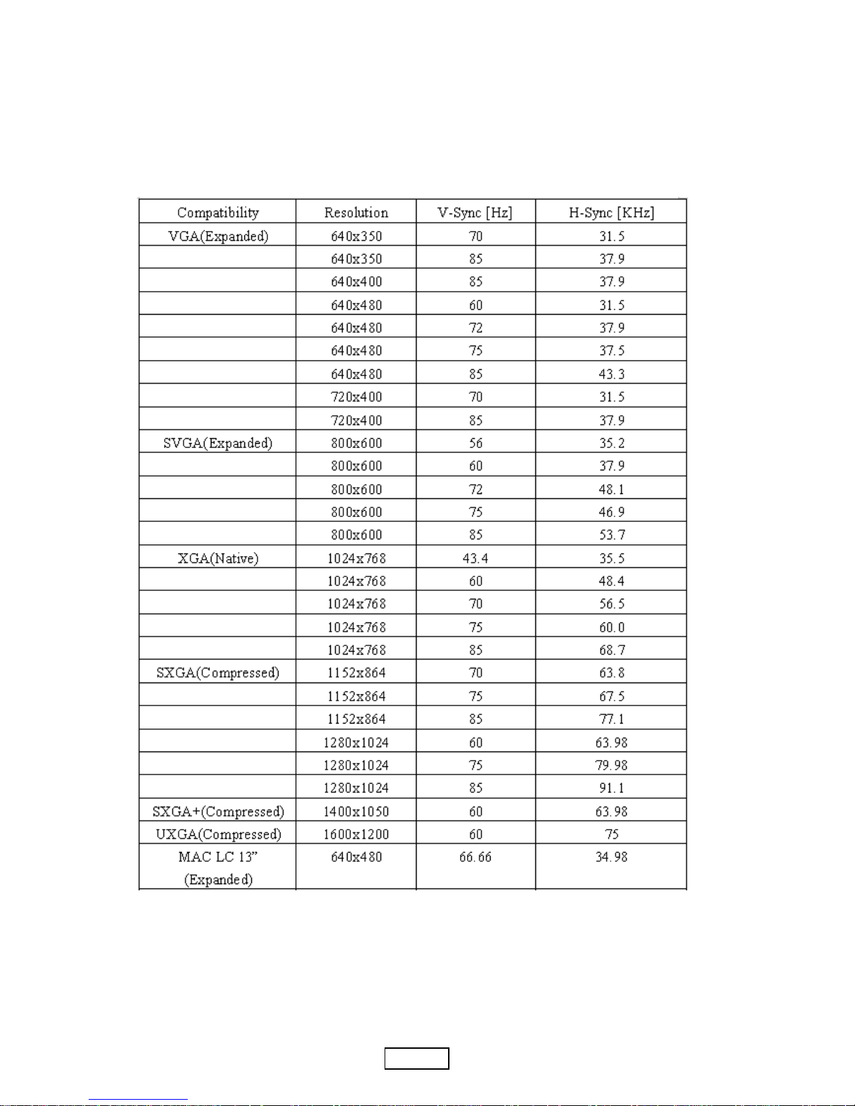
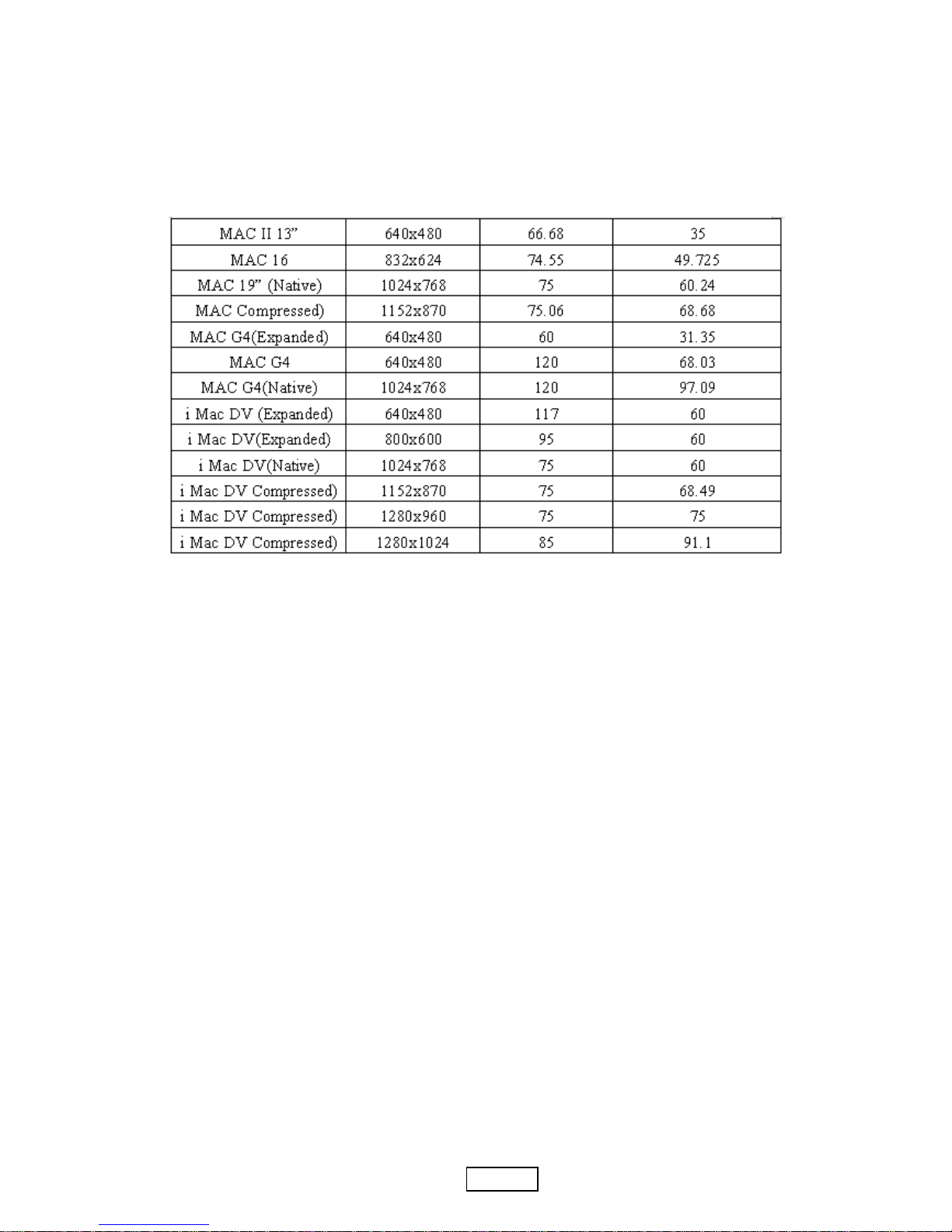
1-6 Compatible Modes
Analog
Page 10
1-5 PJ755D
ViewSonic Corporation
Page 11
1-6 PJ755D
ViewSonic Corporation
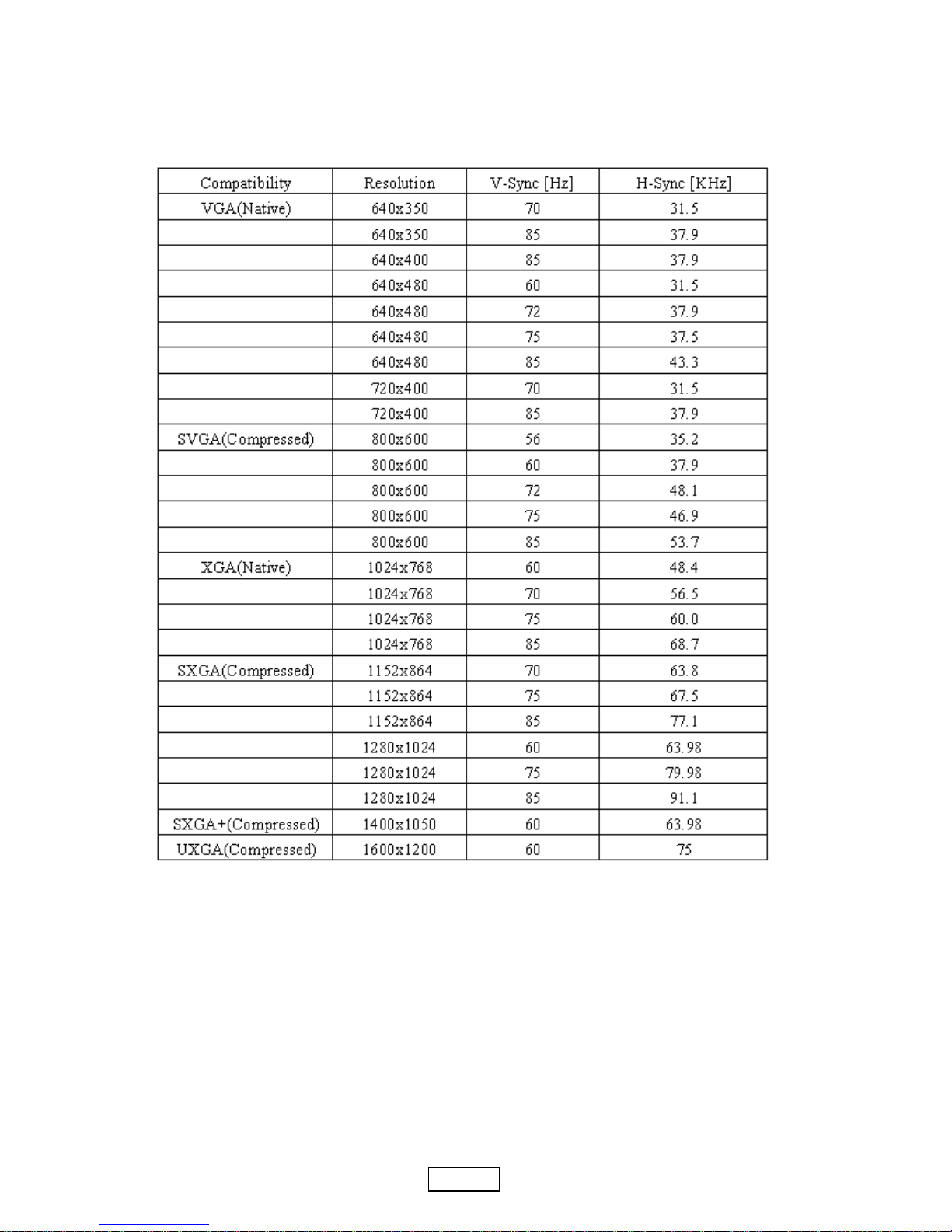
Digital
Page 12
PJ755D2-1
ViewSonic Corporation
Chapter 2
Disassembly Procedure
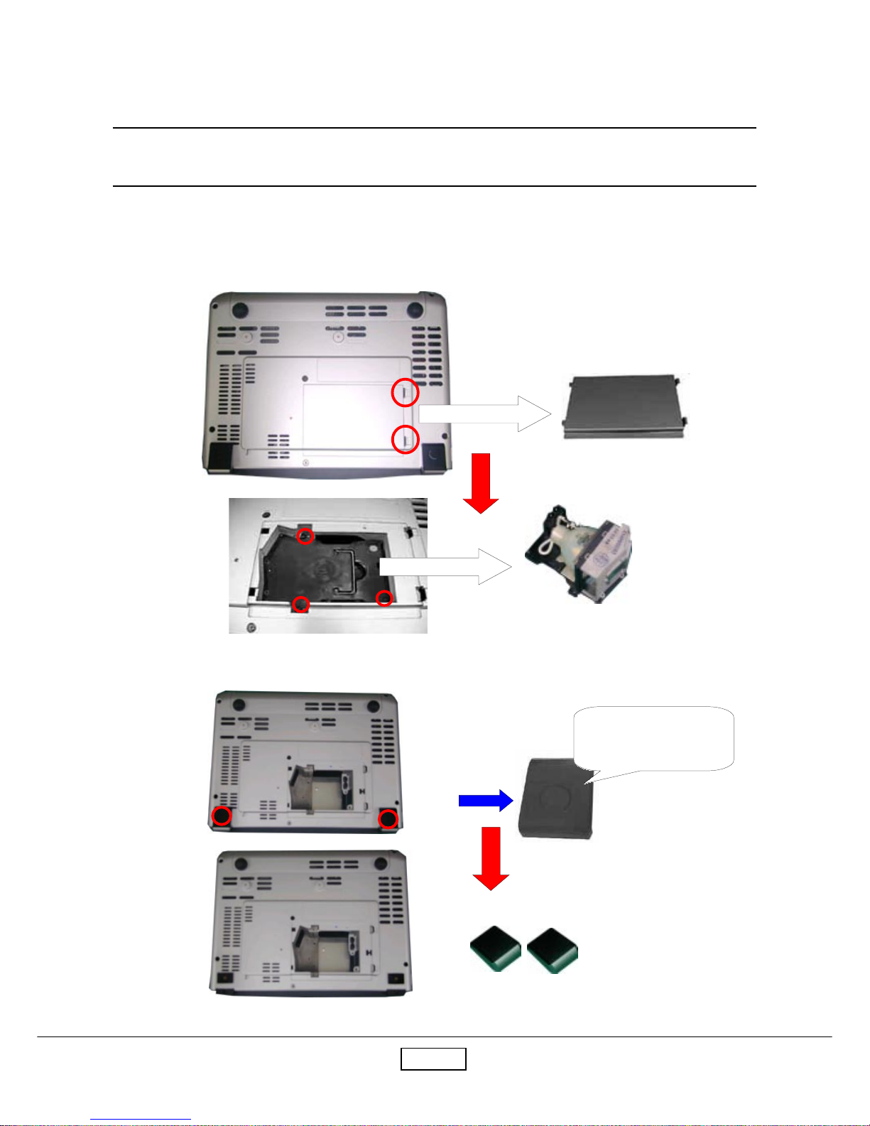
2-1 Disassemble Lamp Module and Elevator Foot
Step1: Turn the unit to the bottom side. Remove Lamp Cover and unscrew three screws to pull
out Lamp Module.
Step2: Unscrew two screws to detach Elevator Foot from Bottom Housing.
Lift it up and then unscrew
the screw
Lamp Module
Lamp Cover
Elevator Foot
Page 13
PJ755D2-2
ViewSonic Corporation
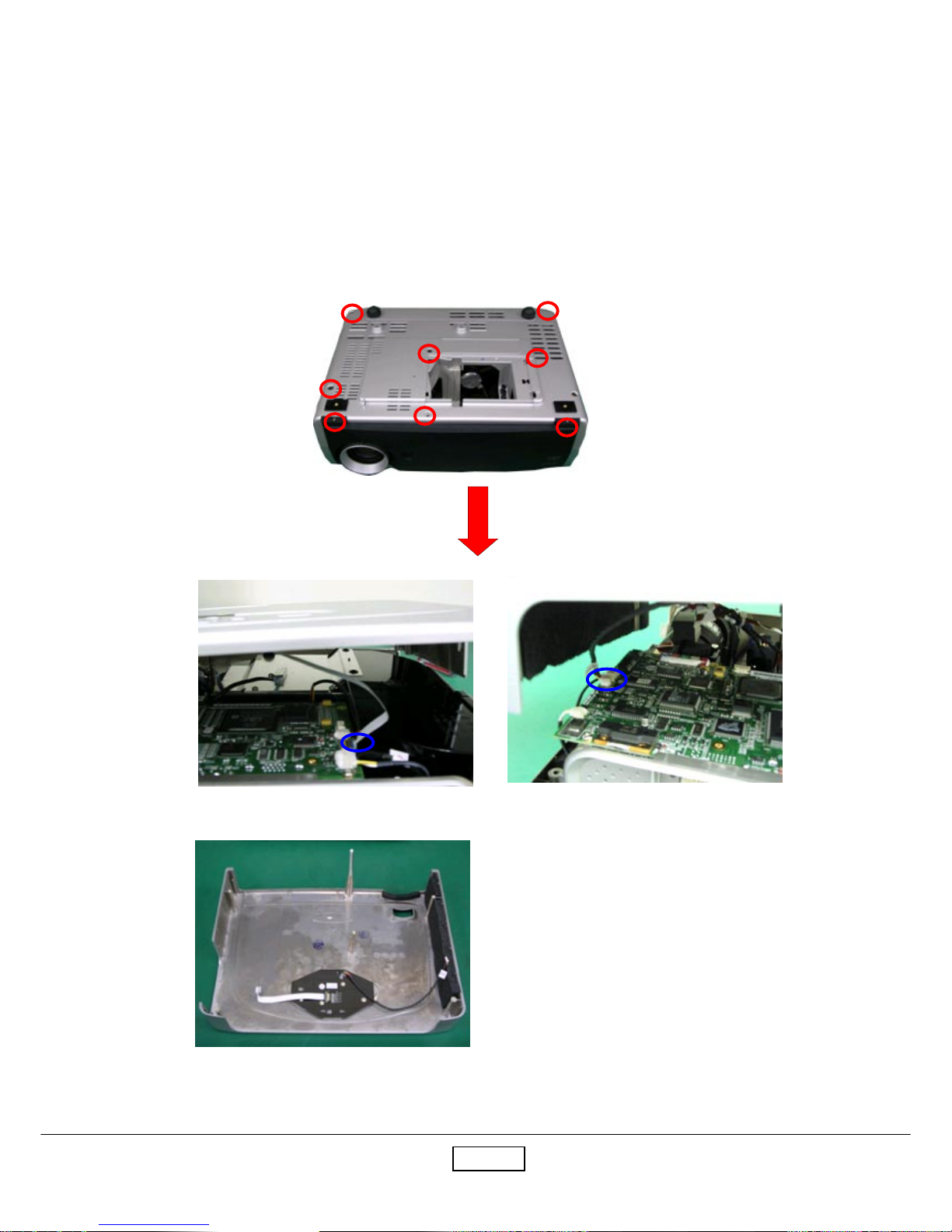
2-2 Disassemble Top Cover and Keypad Board
Step1: Unscrew eight screws and then turn the unit to the top side.
Step2: Disconnect two connectors to remove Top Cover.
Top Cover
Page 14
PJ755D2-3
ViewSonic Corporation
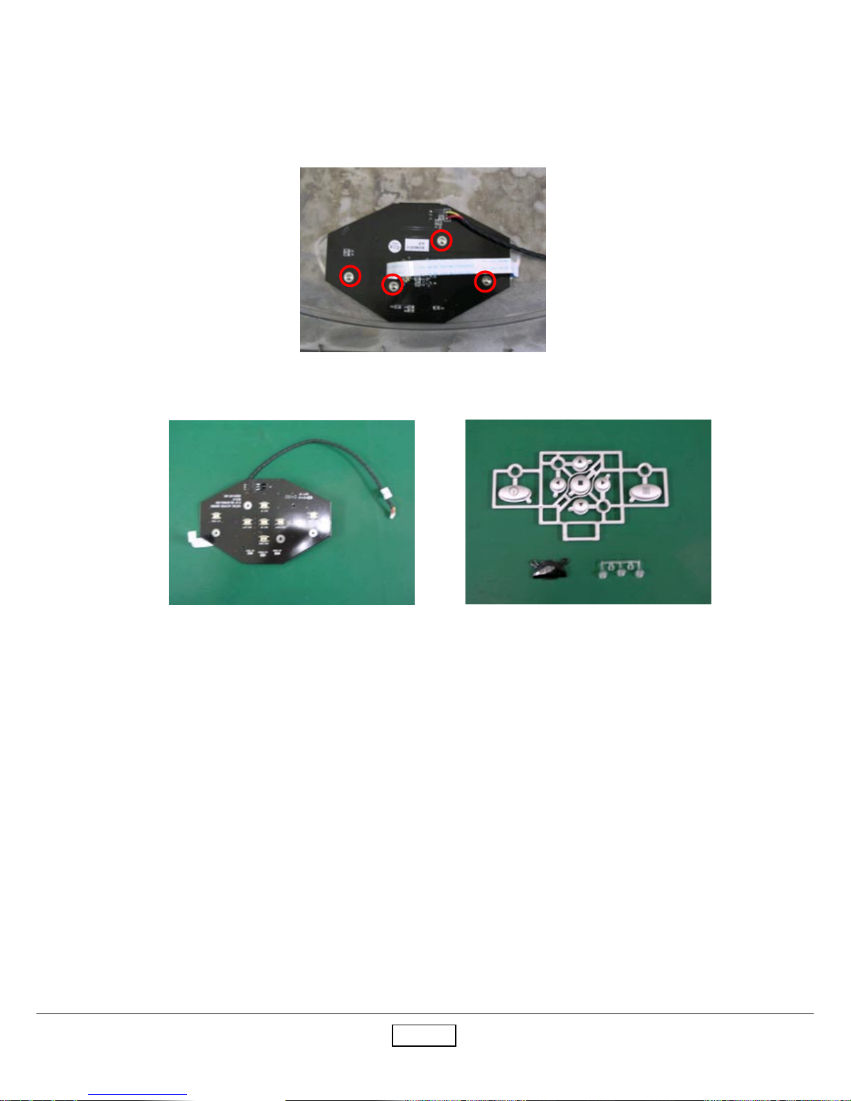
Step3: Unscrew four screws to remove the keypad board, keypad button, IR cover and LED lens.
Keypad Board
Keypad Button
LED Lens
IR Cover
Page 15
PJ755D2-4
ViewSonic Corporation
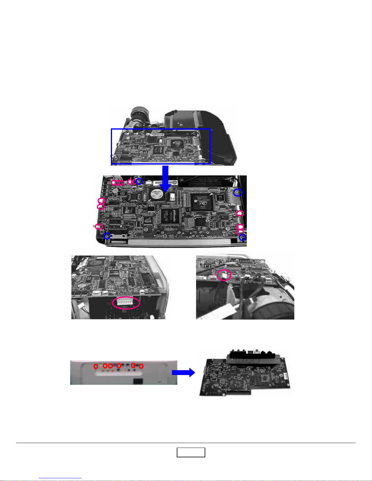
2-3 Disassemble Main Board Module, Wind Tunnel
Module and Fan Guider Module
Step1: Unplug thirteen connectors and unscrew four screws of the main board.
Main Board Module
Step2: Unscrew six hex screws of the rear cover to remove Main Board.
Page 16

PJ755D2-5
ViewSonic Corporation
Wind Tunnel Module
Fan Guider Module
Step3: Unscrew five screws to remove the wind tunnel module and fan guider module.
2-4 Disassemble Lamp Driver Module, LVPS Module
and Axial Fan 92x25 Module
Step1: Unscrew six screws and unplug one wire to remove the lamp driver module.
Lamp Driver Module
Page 17

PJ755D2-6
ViewSonic Corporation
Step2: Unscrew four screws.
Step3: Pull up LVPS Module, unplug the wire and unscrew one screw to detach EMI Ground Plate
from LVPS Module.
EMI Ground Plate
L VPS
Step4: Unscrew two screws to remove Axial Fan 92x25 Module.
Axial Fan 92x25 Module
Page 18
PJ755D2-7
ViewSonic Corporation
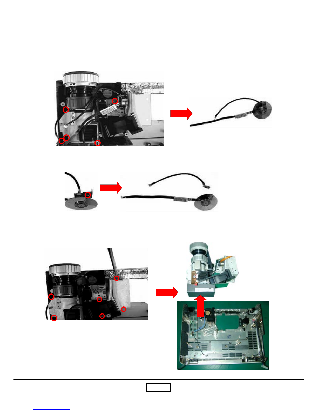
2-5 Disassemble Color Wheel , Photo Sensor Board,
Optical Engine Module and Blower Fan 60x25
Module
Step1: Unscrew five screws to remove Color Wheel.
Color Wheel and Photo Sensor Board
Step2: Unscrew one screw to reomove Color Wheel and Photo Sensor Board.
Color Wheel
Photo Sensor Board
Step3: Unscrew six screws to remove Engine Module from Bottom Housing.
Page 19
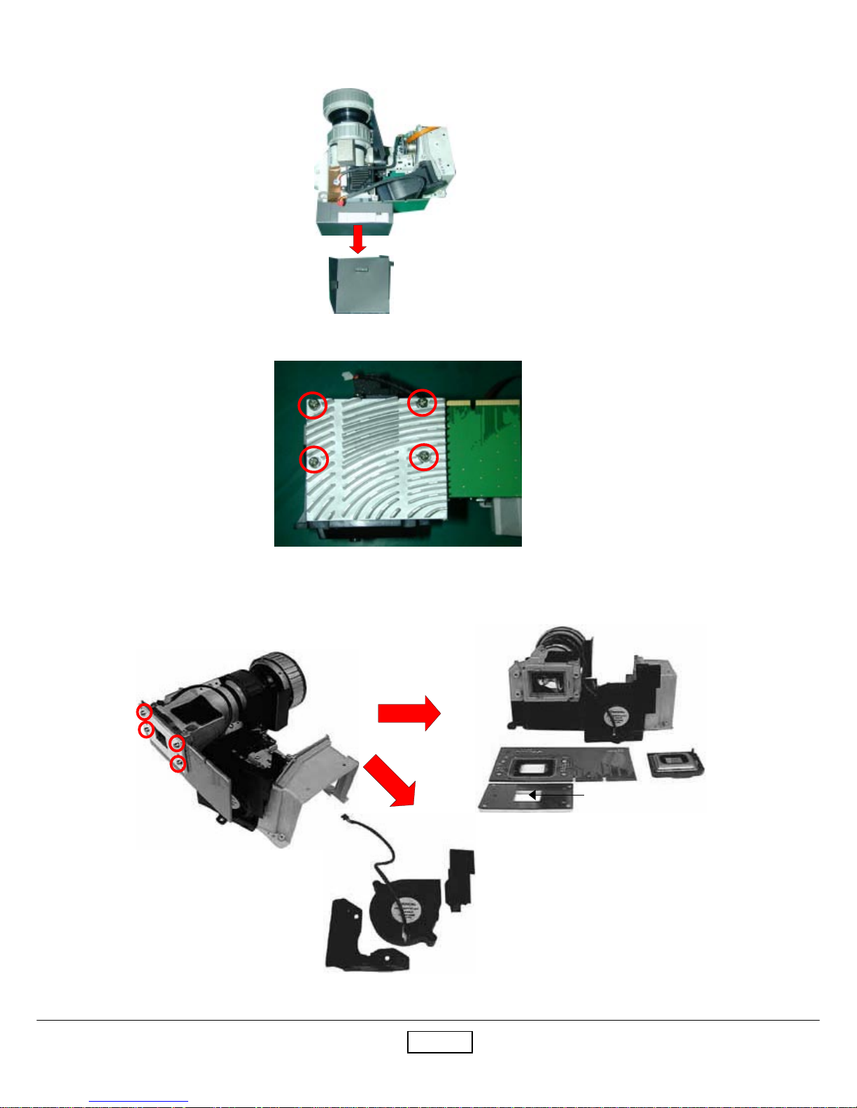
PJ755D2-8
ViewSonic Corporation
Step4: T ear off the mylar.
Step5: Unscrew four screws to remove the DMD heatsink and the heatsink cover.
Step6: Unscrew four screws to remove Bracket Plate, Insulation Mylar, DMD Board and DMD Chip.
Step7: Separate Blower Fan 60x25 Module from Optical Engine Module and then detach Blower Fan
60x25 from the Silicon Rubber.
DMD Board
Bracket Plate
Insulation Mylar
DMD Chip
Blower Fan 60x25
Silicon Rubber
Mylar
Page 20

PJ755D2-9
ViewSonic Corporation
2-6 Disassemble Rear Cover, Speaker, Blower Fan
50x20, Thermal Sensor Board, Interrupt Switch
Module and Bottom Cover
Step1: Unscrew two screws and loosen four tenons to remove the rear cover.
Step2: Unscrew four screws to remove the speakers.
Step3: Unscrew six screws to remove Blower Fan 50x20, Elevator Shading Mylar and Thermal Sensor Board.
Step4: Unscrew two screws to remove Interrupt Switch Module.
Elevator Shading Mylar
Interrupt Switch Module
Blower Fan 50x20
Thermal Sensor Board
Rear Cover
Page 21

PJ755D2-10
ViewSonic Corporation
Step5: Pull the elevator up first and then press the button to remove the elevator module.
1
2
Page 22

PJ755D3-1
ViewSonic Corporation
3-1 Equipment Needed
Chapter 3
Troubleshooting
- PJ755D Projector
- VESA VGA Cable/VESA DVI Cable
- PC (Personal Computer) with analog and digital signal output.
- DVD player with component video (Y, Pb, Pr) and Multi-system (NTSC / PAL / SECAM)
- HDTV Tuner or Source (480i/p, 576i/p, 720p, 1080i)
- PJ755D Remote Controller
Page 23

PJ755D3-2
ViewSonic Corporation
3-2 Main Procedure Description
A. Power Troubleshooting
1.) No Power (All LEDs are off with Power Cord plugged)
- Check the Power Cord.
- Check the Lamp door.
- Ensure the keypad cable is well connected.
Judge
- Change LVPS or Main BD
2.) No Light
Lamp LED Indicator Failed (Lamp LED is red)
- Check if all wires are well connected inside.
- Check Lamp Module
Temp LED Indicator Failed (Temp RED is red)
- Turn on Main Power again.
- Check Fan Module.
- Check Thermal BD.
- Check Thermal Switch.
Judge
- Change Lamp Driver or Main BD.
B. Image Troubleshooting
1.) No image on the screen.
- Ensure the signal cable and source are working fine.
- Press SOURCE button to re-catch the signal again.
Judge
- Change Main BD or DMD BD or DMD Chip
2.) The image displayed with color issue
- Ensure the signal cable and source are working fine.
- Check if the I/O connector is loose or not.
- Check Main BD if the image displayed without color abnormal issue when you input the signal
with other ports.
- Check Photo Sensor BD if the image displayed with color flicking issue.
Judge
- Adjust Brightness-R/G/B.
*Note1
- Adjust Color Wheel index delay.
*Note2
- Change Main Board.
Page 24

PJ755D3-3
ViewSonic Corporation
Note1 : ( Press Power Up Down and Right button to enter Engineer Model)
Enter Engineer Mode first and choose Engineer Mode 3 to adjust Brightness-R/G/B.
Note2 :
Enter Engineer Mode fisrt and choose Engineer Mode 1 to adjust Color Wheel
Index
3.) The image displayed with picture noise issue.
- Press SOURCE button to re-catch the signal again.
- Check the signal cable.
- Check Main BD if there is no picture noise issue when you input the signal with the other
connector.
Judge
- Change Main Board.
4.) The image displayed with Dead Pixel/Line issue.
- Check DMD chip if the bright dot issue exists when you input the signal.
Judge
- Change DMD Board or DMD Chip.
5.) The image displayed with focus issue.
- Adjust Focus Ring.
- Ensure the projection distance is in spec.
Judge
- Change Optical Engine Module
6.) The image displayed with flicker issue.
- Check the Lamp Module
- Ensure the signal cable works well.
- Press SO URCE button to re-catch the signal again.
Judge
- Change Main Board or DMD Board.
7.) The image displayed with uniformity issue.
- Ensure the projection lens is clean.
- Replace the lamp if the brightness is less than spec.
Judge
- Change the Optical Engine Module.
Page 25

PJ755D3-4
ViewSonic Corporation
8.) The image displayed with line bar issue.
- Check if the line bar issue that can be fixed by Frequency function of OSD menu or not.
Judge
- Change Main Board.
C. Audio Troubleshooting
1.) No Sound Output.
- Check if Mute function has been activated or the volumn is set to the minimun.
- Ensure the signal cable and Source are working fine.
- Use the new Speaker for the Sound output test.
(Replace the speaker if the new speaker works fine with the unit.)
- Check the Speaker wire that has broken issue or not.
Judge
- Change Main Board
2.) Sound Output With Noise.
- Ensure the signal cable and source are working fine.
- Ensure the volume has not been set to the maximum
(Due to the output power of internal speaker is 2W only.)
It might has the noise issue if the volume is set to the maximum.)
- Use the new speaker for the test.
(Replace the speaker if the new speaker works fine with the unit.)
- Check if the speaker wire is broken or not.
Judge
- Change Main Board
D. Remote Control Troubleshooting
The OSD menu cannot show on the screen when you press the menu button on the remote
controller.
- Replace the new battery if there is no laser output when you press the laser button on
the remote controller.
- Replace a new remote controller if there is OSD menu showing on the screen when you
press the menu button on the keypad.
Judge
- Change Main Board or Keypad Board.
Page 26

PJ755D
4-1
ViewSonic Corporation
4-1 Product
- PJ755D
4-3 Test Condition
Chapter 4
Function Test and Alignment
Procedure
- IBM PC with XGA resolution (Color Video Signal & Pattern Generator)
- DVD player with component video (Y , Pb, Pr) and Multi-system (NTSC/PAL/SECAM)
- HDTV Tuner or Source (480i/p,576i/p,720p,1080i)
- CHROMA 2327
- Circumstance Brightness
1.) Dark room less than 10 lux for functional inspection.
2.) Circumstance brightness over than 500 lux for external inspection.
- Inspection Distance
1.) About 1.5~3m for functional inspection (The prosection distance has to base on the
screen size till 60 inches)
2.) 30cm for external inspection.
- Screen Size : 60 inches diagonal (wide)
- Should be run-in for 2 hours after repair.
1.) In room temperature
2.) With cycled display colors (R,G,B,White) *Note 1
- Run-in Time: (CT-FL-03002)
After changing all materials:
1.For DC-DC and Ballast, it will run-in 2 hours.
2.For DMD BD, Main BD,Thermal BD and Engine,it will run-in 4 hours.
3.No Fault Fault (NFF): it will run-in 4 hours.
4.Auto Shutdown: it will run-in 6 hours.
*Note1: Please enter Engineer Mode to select run-in function.
Notice: The procedure for entering Engineer Mode: Press power Up, Down, Right button.
4-2 Test Equipment
Page 27

PJ755D
4-2
ViewSonic Corporation
4-4 Test Display Modes & Pattern
4-4.1 Compatible Modes
- Analog
Page 28

PJ755D
4-3
ViewSonic Corporation
- Digital
Page 29

PJ755D
4-4
ViewSonic Corporation
4-4.2 Function Test Display Pattern
- PC Signal
metI tnetnoCtseT nrettaP noitacificepS krameR
1
&ycneuqerF
gnikcarT
erioMeniLeniF
ybesionyvawlausivetanimilE
gnikcarTroycneuqerF,cnysR
.noitceles
1erugiF
2ssenthgirB/tsartnoC
/elacSyarG61
elacsWBGR46
ebdluohslevelyarG
roloctuohtiwdnaelbahsiugnitsid
.lamronba
erugiF
3,2
3
etihWdnaB,G,R
ecnamrofreProloC
dnaB,G,R
roloCetihW
ebdluohsrolocB,G,RhcaE
lamronbaroloctuohtiwlamron
.eussi
Fi erug
47~
4ytimrofinUneercSetihWlluF
htiwtnailpmocebdluohS
)muminiM(.%56
Fi erug7
5
thgirB(lexiPdaeD
)lexip
kcalBlluFlexipthgirbynatpeccatonnaC8erugiF
kraD(lexiPdaeD
)lexip
etihWlluF
dluohslexipdaedfosrebmunehT
.lexip6ottnuomarorellamseb
7erugiF
6)thgirB(hsimelB
yarG/kcalBlluF
03
ebtonnachsimelbthgirbehT
htiwraeppamelborpehtfitpecca
.nrettap03yraG
,8erugiF
9
7)kraD(hsimelB
eulB/etihwlluF
06
tpeccaebtonnachsimelbkradehT
06eulBhtiwraeppamelborpehtfi
.nrettap
erugiF
01,7
8sucoFnrettaPtxeT
ebdluohsrenrocehtnitxetehT
.gnirsucofehttsujdaretfaraelc
erugiF
11
9yradnuoBemarFyradnuoB
oedivfonoitisop.treVdnA.zroH
ehtebotelbatsujdaebdluohs
.emarfneercs
erugiF
21
Page 30

PJ755D
4-5
ViewSonic Corporation
Figure 2.Gray Scale Pattern
Page 31

PJ755D
4-6
ViewSonic Corporation
Page 32

PJ755D
4-7
ViewSonic Corporation
- Video & Audio Signal
Page 33

PJ755D
4-8
ViewSonic Corporation
4-5 Inspection Procedure
- Elevator Function
1. Please check and ensure the function of elevator is work as well.
2. If not, please return the unit to repair area.
- Keypad Function (Including Remote Control)
1. Please check and ensure the control function of keypad is work as well.
2. If not, please return the unit to repair area.
- Clock and Clock phase
Test Signal:1024 x 768 @ 75Hz
Test Pattern:Fine Line Moire Pattern
1. Check and see If image sharpness and focus in well performed.
2. If not, readjust by following steps.
(a) Enter Image-I, and then select “Frequency” function to adjust the total pixel number
of pixel clock in one line period.
(b) Then select “phase” function and use right or left button to adjust the value to minimize
video flicker.
- R, G, B and white color contrast
Test Signal:1024 x 768 @ 75Hz
Test Pattern:64 RGBW scale pattern
1. Please check and ensure if each color is normal and distinguishable.
2. If not, please return the unit to repair area.
- Screen Uniformity
Test Signal:1024 x 768 @ 75Hz
Test Pattern:Full white pattern
1. Please check and ensure the unit is under the spec. (60% Minimum)
2. If not, please return the unit to repair area.
- Dead pixel (Bright pixel)
Test Signal:1024 x 768 @ 75Hz
Test Pattern:Full black pattern
1. Please check and ensure the unit is under the spec.
2. If not, please return the unit to repair area.
Page 34

PJ755D
4-9
ViewSonic Corporation
- Dead pixel (Dark pixel)
Test Signal:1024 x 768 @ 75Hz
Test Pattern:Full white pattern
1. Please check and ensure the unit is under the spec. (Pixel number should be smaller
or amount to 6 pixels)
2. If not, please return the unit to repair area.
- Blemish (Bright)
Test Signal:1024 x 768 @ 75Hz
Test Pattern:Full black and Gray 30 patterns
1. Please check and ensure the unit is under the spec. (The bright blemish should not be
able to see under Gray 30 pattern)
2. If not, please return the unit to repair area.
- Blemish (Dark)
Test Signal:1024 x 768 @ 75Hz
Test Pattern:Full white and Blue 60 patterns
1. Please check and ensure the unit is under the spec. (The dark blemish should not be
able to see under Blue 60 pattern)
2. If not, please return the unit to repair area.
- Focus
Test Signal:1024 x 768 @ 75Hz
Test Pattern:T ext pattern
1. Please check and ensure the unit is under the spec.
2. If not, please return the unit to repair area.
- Boundary
Test Signal:1024 x 768 @ 75Hz
Test Pattern:Boundary frame pattern
1. Please check and ensure the unit is under the spec. (The horizontal and vertical
position of image should be adjustable to be the screen frame.)
2. If not, please return the unit to repair area.
Page 35

PJ755D
4-10
ViewSonic Corporation
- Video
Test Signal:Composite video,S-Video and Component video
Test Pattern:NTSC,PAL,SECAM
1. Please check and ensure the unit can display the video signal without color abnormal
or image abnormal issue.
2. If not, please return the unit to repair area.
- HDTV
T est Signal:HDTV signal
Test Pattern:480i/p,576i/p,720p,1080i
1. Please check and ensure the unit can display the HDTV signal without color abnormal
or image abnormal issue.
2. If not, please return the unit to repair area.
- Audio
1. Please check and ensure the function of audio is work as well.
(Volume,Treble,Bass,Mute)
2. If not, please return the unit to repair area.
Page 36

P755D5-1
ViewSonic Corporation
Chapter 5
Firmware Upgrade Procedure
5-1 Equipment Needed
Software :
- Configdata.hex
- Flasher.hex
- FlashUpgrader.exe
- Gui.exe
- PWSDK.inf
- Romcode.hex
Hardware :
- Power Cord
- Cable RS232 To Mini Din 3Pin (P/N: 42.86301.001-A)
- PC or Laptop
- PJ755D Projector
5-2 Hardware Setup Procedure
1. Connecting RS232 Cable between PC and PJ755D Projector.
2. Connecting Power Cord.
P/N: 42.86301.001-A
RS232 Cable
Mini Din 3pin Port
Page 37

PJ755D5-2
ViewSonic Corporation
Step1. Execute the “FlashUpgrader.exe” program.
5-3 Firmware Program Installation Procedure
Step2. Click Choose to get the file directory
Page 38

P755D5-3
ViewSonic Corporation
Step3. Select <pwSDK.inf> file and open it.
Step4. Select Connection to Serial, COM Port to Right COM and Baud Rate to
115200.
Page 39

PJ755D5-4
ViewSonic Corporation
Step5. Click Flash to start the firmware upgrade procedure and keep press the
projectors power button immediately until download gui.hex to 10%.
Notice: The Lamp and Temp LEDs are red and Power LED is green.
Step7. After downloading all files, enter the Engineer mode to check the F/W version.
*Notice
Notice: The procedure for enter Engineer mode:
Press Power, Up, Down, Right buttons sequentially to enter Engineer Mode.
The F/W version V2.1 2004-10-12 can be found on the upper-right corner of
Engineer Mode menu.
Step6. Disconnect Power Cord and reconnect it.
Page 40

PJ755D6-1
ViewSonic Corporation
Chapter 6
EDID Procedure
6-1 Equipment Needed
- PC or Laptop
- EDID Fixture for PJ755D (P/N: 80.00001.001) (Fixture 1 or Fixture 2)
- DFP to DVI Cable
- Power Adapter
- RS-232 Cable
- VGA Cable
- Power Cord
- PJ755D
6-1.1 Hardware
6-1.2 Software
- EDID program
- VIEWSONIC_PJ755D_EDID_A.INI
- Window 98/ME/NT/XP
EDID Fixture
P/N:80.00001.001
DFP to DVI Cable
P/N: 42.81702.001
RS-232 Cable
P/N: 42.55708.001
VGA Cable
P/N:42.53001.051
Power Adapter
P/N: 47.53402.004
Page 41

PJ755D6-2
ViewSonic Corporation
6-2 Setup Procedure
Step1. Connect Power Adapter with fixture.
Step2. Make sure the JP1and JP5 are closed and JP2 is open.
Step3. Connect P2 of the fixture with VGA Port of PJ755D by the VGA Cable.
Step4. Connect P3 of the fixture with DVI Port of PJ755D by the DFP to DVI cable.
Step5. Connect P4 of the fixture with COM Port of PC by the RS232 Cable.
Step6. Turn on the power of the fixture.
P3
P2
JP5
JP1
JP2
P4
6-2.1 Fixture 1
COM1
DVI
VGA
Page 42

PJ755D6-3
ViewSonic Corporation
6-2.2 Fixture 2
Step1. Connect Power Adapter with fixture.
Step2. Make sure the JP3 is closed (short) and JP4 is open.
Step3. Connect P2 of the fixture with VGA Port of PJ755D by the VGA Cable.
Step4. Connect P3 of the fixture with DVI Port of PJ755D by the DVI cable.
Step5. Connect P1 of the fixture with COM Port of PC by the RS232 Cable.
P1
P3
P2
Page 43

PJ755D6-4
ViewSonic Corporation
6-3 EDID Upgrade Procedure
Step1. Execute EDID program
Step2. Press Mode button.
Page 44

PJ755D6-5
ViewSonic Corporation
Step3. Choose the VIEWSONIC_PJ755D_EDID_A file and then press open button.
Step4. Press port setting button. Setting the right COM port.
Note: If you only upgrade VGA, the power cord should be connected to the
projector, but for the DVI upgrade only, it is not necessary.
Note
Page 45

PJ755D6-6
ViewSonic Corporation
Step5. Key-in S/N to the blank beside Barcode and press the Write
button.
Step6. Press OK button.
Barcode
Write Button
Page 46

PJ755D6-7
ViewSonic Corporation
Step7. Press OK button.
Step8. After finishing the above action, OK message will appear on the screen.
This means the EDID is successfully written in.
Page 47

PJ755D6-8
ViewSonic Corporation
Step9. Methods to check S/N:
For digital mode, choose Digital, check Trans, and then press Read.
Read
Digital
Step10. The messages of OK and the Digital Values will show.
Digital Values
Trans
Page 48

PJ755D6-9
ViewSonic Corporation
Step12. The messages of OK and the Analog Values will show.
Analog Values
Step11. For analog mode, choose Analog, check Trans, and then press Read.
Analog
Read
Trans
Page 49

PJ755D
7-1
ViewSonic Corporation
Appendix A
Exploded Overview
Page 50

PJ755D
7-2
ViewSonic Corporation
Page 51

PJ755D
7-3
ViewSonic Corporation
Page 52

PJ755D
7-4
ViewSonic Corporation
Page 53

PJ755D
7-5
ViewSonic Corporation
Page 54

PJ755D
7-6
ViewSonic Corporation
Page 55

PJ755D
7-7
ViewSonic Corporation
Page 56

PJ755D
7-8
ViewSonic Corporation
Page 57

PJ755D
7-9
ViewSonic Corporation
Page 58

PJ755D
7-10
ViewSonic Corporation
Page 59

PJ755D
7-11
ViewSonic Corporation
Page 60

PJ755D
7-12
ViewSonic Corporation
Appendix B
I. Serial Number System Definition
Serial Number for Projector
EX : PDH044200007
This label “PDH044200007” represents Worldwide Model for Projector PJ755D,
“04” means the unit was made in 2004 year. “42” means the unit was made on week
42. “00007” means the sequence code of the unit.
XXX - YY - WW - XXXXX
1
2
3 4
1
2
3
4
: Regional Product ID Code
: Last two digits of manufacturing year
: Manufacturing week
: Sequence number
Page 61

PJ755D
7-13
ViewSonic Corporation
*Reader’s Response*
Dear Readers:
Thank you for your backing our service manual up. In order to refine our content of the
service manual and satisfy your requirement. We expect you can offer us some precious
opinions for reference.
Assessment:
:emaN:eltiT
:ynapmoC
:ddA
:leT:xaF
:liam-E
metI tnellecxE dooG riaF daB
tnetnoClaunaMecivreS.1
tuoyaLlaunaMecivreS.2
gnitsildnamrofehT.3
tinU tnellecxE dooG riaF daB
noitcudortnI.1
erudecorPylbmessasiD.2
gnitoohselbuorT.3
erudecorPtnemngilA&tseTnoitcnuF.4
erudecorPedargpUerawmriF.5
erudecorPni-yekCDD.6
xidneppA.7
B. Are you satisfied with the PJ755D service manual?
C. Do you have any other opinion or suggestion about this service manual?
Reader’s basic data:
After your finishing this form, please send it back to ViewSonic Co. Customer Service
Dept. by fax: 909-839-7943.
A. What do you think about the content after reading PJ755D Service Manual?
 Loading...