

Page 1

Service Manual
ViewSonic PJ452-2
Model No. VS11334
LCD Projector
ViewSonic
(PJ452-2_SM Rev. 1a May. 2006)
381 Brea Canyon Road, Walnut, California 91789 USA - (800) 888-8583
Page 2

Copyright
Copyright
2006 by ViewSonic Corporation. All rights reserved. No part of this publication may be
¤
reproduced, transmitted, transcribed, stored in a retrieval system, or translated into any language or
computer language, in any form or by any means, electronic, mechanical, magnetic, optical, chemical,
manual or otherwise, without the prior written permission of ViewSonic Corporation.
Disclaimer
ViewSonic makes no representations or warranties, either expressed or implied, with respect to the
contents hereof and specifically disclaims any warranty of merchantability or fitness for any particular
purpose. Further, ViewSonic reserves the right to revise this publication and to make changes from time
to time in the contents hereof without obligation of ViewSonic to notify any person of such revision or
changes.
Trademarks
Optiquest is a registered trademark of ViewSonic Corporation.
ViewSonic is a registered trademark of ViewSonic Corporation.
All other trademarks used within this document are the property of their respective owners.
ECR Number
1a
5/15/06
Revision History
Description of Changes
Initial Release
EditorRevision SM Editing Date
BonnieT
ViewSonic Corporation Confidential
i
-
Do Not Copy PJ452-2
Page 3

TABLE OF CONTENTS
1. Precautions and Safety Notices
2. Specification
3. Names of each part
4. Adjustment
5
. Troubleshooting
6
. Service points
. Wiring diagram
7
8
. Disassembly diagram
9. Replacement parts list
. RS-232C commands
10
11. Block diagrams
12. Connector connection diagram
13. Basic dircuit diagram
1
2
3
5
11
16
30
34
42
44
52
53
54
ViewSonic Corporation Confidential
ii
-
Do Not Copy PJ452-2
Page 4
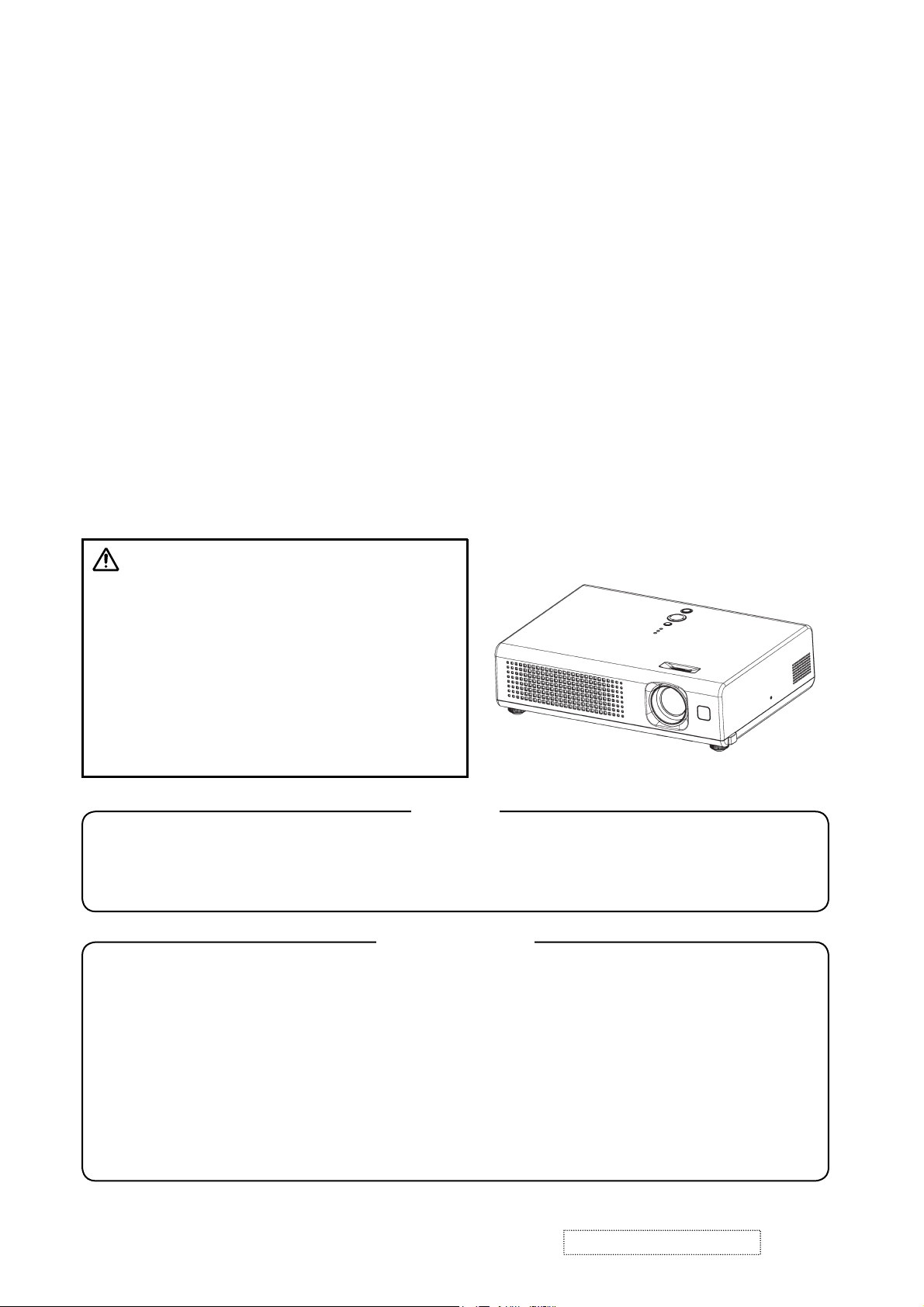
1. Precautions and Safety Notices
1. When replacing the lamp, use care to avoid burns to your fingers. The lamp becomes very hot
during operation.
2. Never touch the lamp with your fingers as body oil transferred to the lamp can damage the
lamp’s useful life.
3. Never drop the lamp or jar it in any manner. This may cause the lamp to burst.
4. This projector is provided with a high voltage circuit for the lamp. Do not touch any electric
part or component after the projector has been turned on and is operating. Doing so could
induce a severe shock causing injury or death.
5. Do not touch the exhaust fan, nor block its air flow, during operation, as the fan is hot.
6. The LCD module assembly can be easily damaged during service. If replacing the LCD
Lens/Prism assembly, do not hold the FPC of the LCD module assembly.
7. Use only the cables which are included with the projector, or are specified in this manual.
Warning
The technical information and parts shown in this
manual are not to be used for: the development,
design, production, storage or use of nuclear, chemical,
biological or missile weapons or other weapons of
mass destruction; or military purposes; or purposes that
endanger global safety and peace. Moreover, do not
sell, give, or export these items, or grant permission for
use to parties with such objectives. Forward all inquiries
to the SUPPLIER.
Caution
Be sure to read this manual before servicing. To assure safety from Þ re, electric shock, injury, harmful
radiation and materials, various measures are provided in this Multimedia LCD Projector. Be sure to
read cautionary items described in the manual to maintain safety before servicing.
Service Warning
1. When replace the lamp, to avoid burns to your Þ ngers. The lamp becomes too hot.
2. Never touch the lamp bulb with a Þ nger or anything else. Never drop it or give it a shock. They may
cause bursting of the bulb.
3. This projector is provided with a high voltage circuit for the lamp. Do not touch the electric parts of
power unit (circuit/ballast), when turn on the projector.
4. Do not touch the exhaust fan, during operation.
5. The LCD module assembly is likely to be damaged. If replacing to the LCD/PRISM assembly, do not
hold the FPC of the LCD module assembly.
6. Use the cables which are included with the projector or speciÞ ed.
ViewSonic Corporation
1
Confidential -Do Not Copy PJ452-2
Page 5
Features
• High Brightness
• Low Noise
• Compact Body
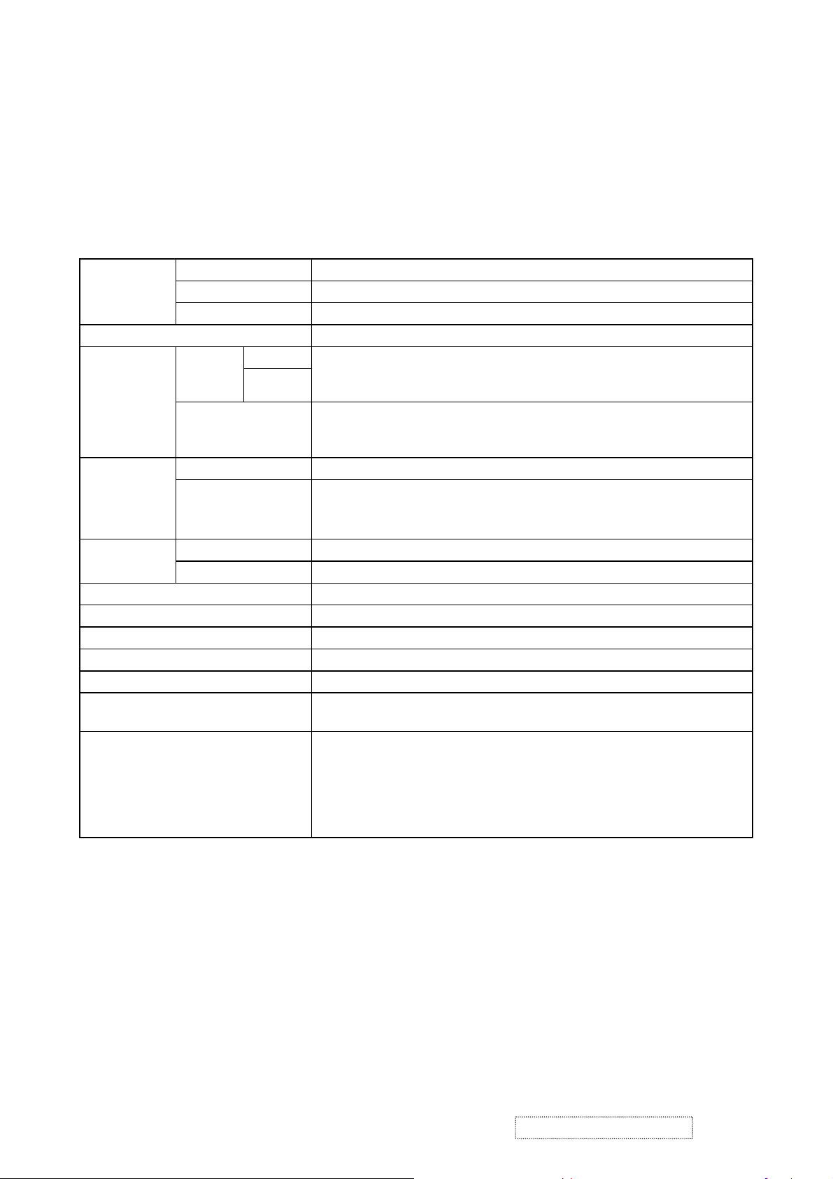
2. Specifications
Liquid clystal
panel
Lamp 165W UHB
RGB
signal
VIDEO
signal
AUDIO
signal
Speaker output 1W(mono)
Power supply AC100~120V/2.7A,AC220~240V/1.5A
Power consumption 240W
Dimensions 285 (W) x 73 (H) x 202 (D) mm (Not including protruding parts)
Weight 2.3kg
Temperature range
Accessories
Drive system TFT active matrix
Panel size 1.5cm(0.6type)
Number of pixels 1024(H) x 768(V)
1 Video : Analog 0.7Vp-p(75Ω termination)
RGB IN
RGB OUT
VIDEO IN 1.0Vp-p (75Ω termination)
S-VIDEO IN
AUDIO IN 200mVrms, 47kΩ or more (max. 3.0Vp-p)
AUDIO OUT 0~200mVrms, output impedance 1kΩ (max. 5.0Vp-p)
H/V. sync. : TTL level (positive/negative)
2
Composite sync. : TTL level
Video:Analog 0.7Vp-p, 75Ω output impedance (positive)
H/V. sync.: TTL level (positive/negative)
Composite sync.: TTL level
Y signal: 1.0±0.1Vp-p, (75Ω termination)
C signal: 0.286±0.1Vp-p (NTSC burst signal, 75Ω termination)
0.3±0.1Vp-p (PAL/SECAM burst signal, 75Ω termination)
Operation : 5~35°C
Storage : -20~60°C
Remote control x 1pcs
RGB cable x 1pcs
Power cords x 3pcs
Batteries x 2pcs
Filter cover for bottom up use x 1pcs
Lens cap x 1pcs
Strap x 1pcs
User’s manuals x 1set
ViewSonic Corporation
2
Confidential -Do Not Copy PJ452-2
Page 6
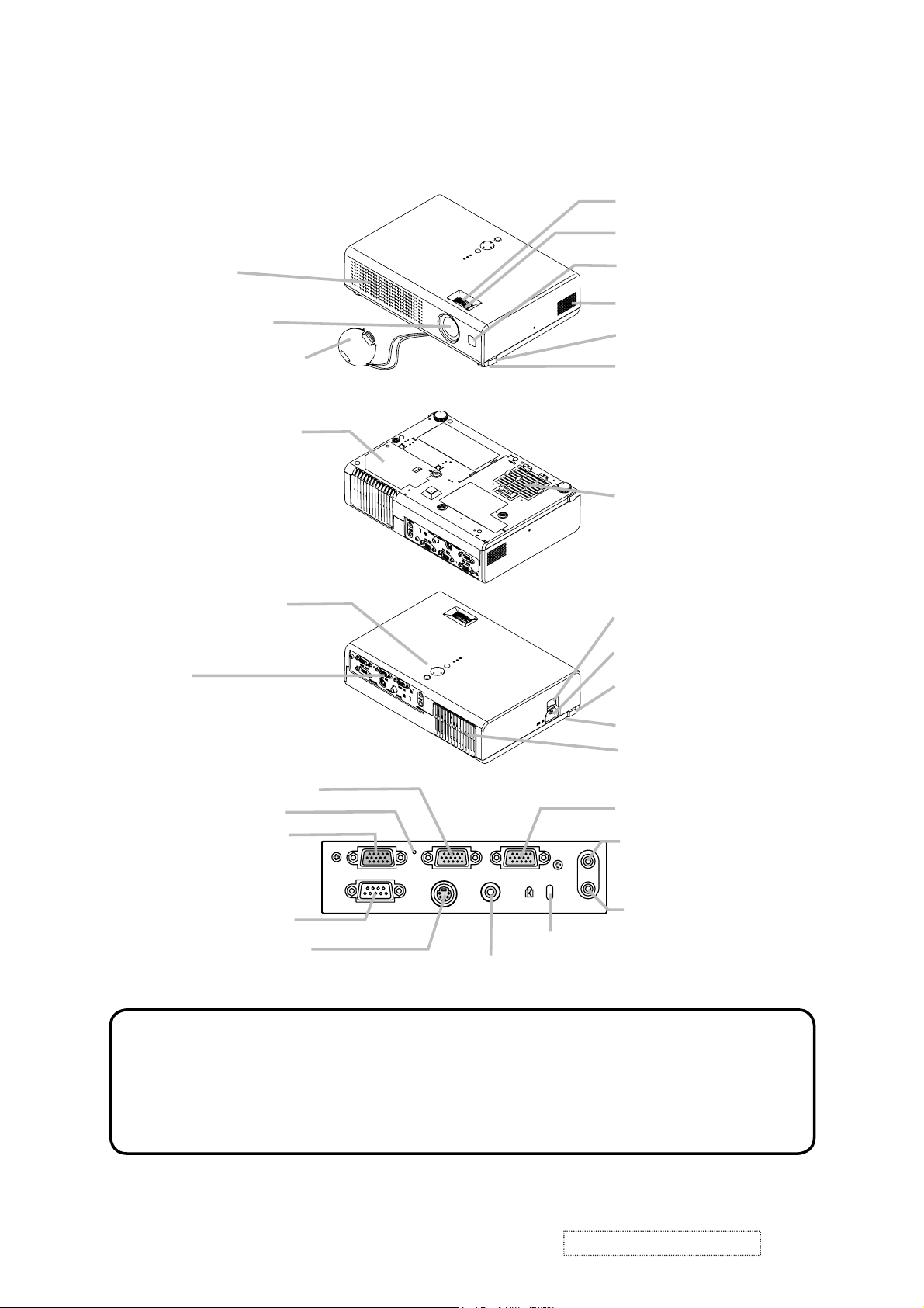
3. Names of each part
Part names
Projector
Vent
Lens cover
Lamp cover
(Lamp unit is inside.)
Control buttons
Lens
Zoom ring
Focus ring
Remote sensor
Speaker
Elevator button
Elevator foot
Front-Right side
Filter cover
(Air Þlter and intake vent
are inside.)
Bottom side
Power switch
AC inlet
Ports
(See below.)
Elevator button
Elevator foot
Rear-Left side
Vent
RGB IN2 port
Restart switch
RGB OUT port
CONTROL port
S-VIDEO port
RGB IN2 RGB OUT RGB IN1
CONTROL
S-VIDEO VIDEO
Ports
AUDIO IN
Kensington lock slot
RGB IN1 port
AUDIO-OUT port
OUT
AUDIO-IN port
VIDEO port
NOTE (*) About Restart switch: This projector is controlled by an internal
microprocessor. Under certain exceptional circumstances, the projector may not
operate correctly and the microprocessor will need to be reset. In such a case,
please push the Restart switch by using a cocktail stick or similar, and before
turning on again, make the projector cool down at least 10 minutes without
operating. Only push the Restart switch in these exceptional instances.
ViewSonic Corporation
3
Confidential -Do Not Copy PJ452-2
Page 7
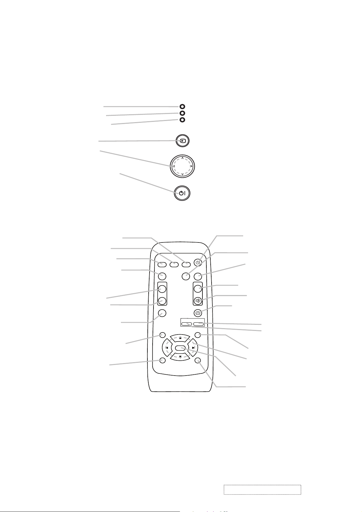
Controls
l
O
Zoom
enu cursor buttons
LAMP indicator
TEMP indicator
POWER indicator
INPUT button
Cursor buttons
▲,▼,◄,►
STANDBY/ON button
emote contro
SEARCH button
RGB button
VIDEO button
ASPECT button
VIDEO
ASPECT
LAMP
TEMP
POWER
INPUT
MENU
STANDBY/ON
SEARCH
RGB
AUTO
STANDBY/ON
BLANK
TANDBY/ON button
AUTO button
BLANK button
MAGNIFY
ON button
OFF button
FREEZE button
POSITION button
ESC button
MAGNIFY
ON
OFF
FREEZE
POSITION
ESC
ENTER
-
VOLUME
KEYSTONE
ZOOM
MUTE
MENU
RESET
V
LUME button
MUTE button
KEYSTONE button
+
+ button
- button
MENU button
M
▲,▼,◄,►
ENTER button
RESET button
ViewSonic Corporation
4
Confidential -Do Not Copy PJ452-2
Page 8
4. Adjustment
4-1 Before adjusting
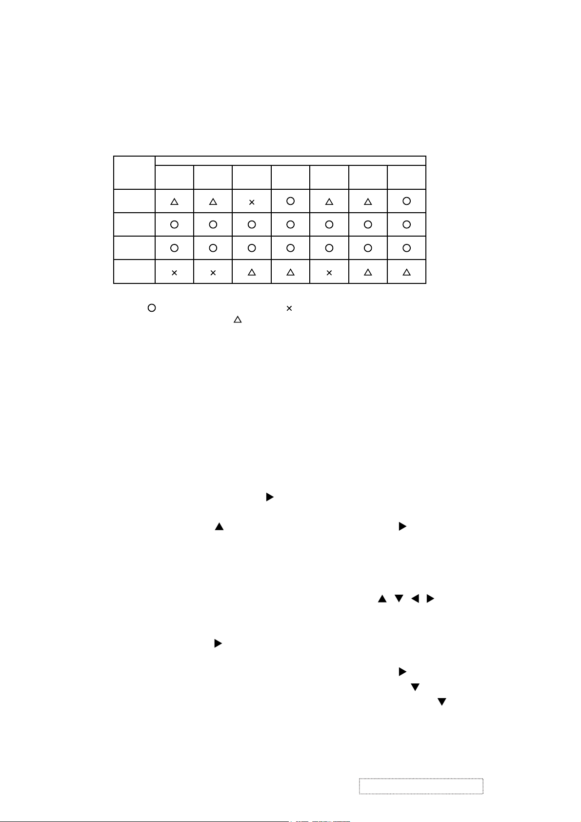
4-1-1 Selection of adjustment
When any parts in the table 4-1 are changed, choose the proper adjusting items with the chart.
Table 4-1: Relation between the replaced part and adjustment
Replaced
part
Dichroic
optics unit
LCD/LENS
prism
assembly
PWB
assembly
Main
Lamp
unit
assembly
Convergence
(Chap.4-2)
E-POS
(Chap.4-3)
(Chap.4-4)
: means need for adjustment. : means not need for adjustment.
Adjustment
Ghost
: means recommended.
Flicker
(Chap.4-5)
NRSH
(Chap.4-6)
White
balance
(Chap.4-7)
Color
uniformity
(Chap.4-8)
4-1-2 Setting of condition before adjustment
1. Before starting adjustment, warm up projector
for about 10 minutes.
2. Set Zoom Wide to Max. And project an image
with more than 1m (40 inches) in diagonal size.
3. Normalizing the video adjustment
Press the [MENU] button to display the Easy
menu. If Advance menu comes up, move to the
Easy menu.
Select RESET in the Easy menu and press [
or [ENTER] button to open the RESET menu
window. Choose EXECUTE with [ ] button.
Note that no signal input may not allow to reset
the adjustments.
4. Select PICTURE > GAMMA in the Advance
menu to set to DEFAULT1.
Note that PICTURE menu is not selectable with
no signal input displayed.
5. Select PICTURE > COLOR TEMP > CUSTOM
in the Advance menu, then press [ ] or [ENTER]
button to display the equalizing window. Set all
the values of OFFSET and GAIN in the window
to zero.
Caution: Before this performance, make a note
of your customer’s adjustments, because the
data is overwritten.
6. Perform all adjustments from the FACTORY
MENU.
Perform the following operations to display the
FACTORY MENU.
< When you use the remote control… >
a. Press the [MENU] button of remote control to
display the Easy menu. (If the Advance menu
appears, move to the Easy menu from EASY
]
MENU.)
b. Select the [RESET] in the Easy menu, and
then press the [ ] or [ENTER] button.
c. Next, press the [RESET] button one time.
And hold the [RESET] button for 3 seconds
or more (the FACTORY MENU will appear).
< When you use the keypad… >
a. Press the [ ]/[]/[ ]/[ ] button of the projec-
tor to display the Easy menu. (If the Advance
menu appears, move to the Easy menu from
EASY MENU.)
b. Select the [
RESET
] in the Easy menu, and
then press the [ ] button.
c. Next, press the [ ] button one time. And
repress and hold the [ ] button together
with the [INPUT] button for 3 seconds or
more (the FACTORY MENU will appear).
ViewSonic Corporation
5
Confidential -Do Not Copy PJ452-2
Page 9

4-2 Convergence adjustment
Signal pattern for internal adjustment
4-3
E-POS adjustment
(vertical bars adjustment)
Signal pattern for internal adjustment
112/255
4-4 Ghost adjustment
Signals for internal adjustment
30%
30%
0/255
112/255
Adjustment procedure
1. Open FACTORY MENU and then select
OPTION > CNV-V. Use R and/or B so that
three colors of images can be converged at
center, top and bottom of the screen.
2. In the same way, select OPTION > CNV-H and
use R and/or B so that three colors of images
can be converged at center, left and right of the
screen.
Adjustment procedure
1. Make this adjustment after completing the
adjustment 4-2 Convergence adjustment.
2. Choose Advance menu > OPTION > SERVICE
> GHOST > R,G and B, and set them to zero.
3.
Open FACTORY MENU. Select DAC-P > E-POS
> R and use it so that vertical bars can disappear.
4. In the same way, select DAC-P > E-POS > G
and use it so that vertical bars can disappear.
5. In the same way, select DAC-P > E-POS > B
and use it so that vertical bars disappear.
Adjustment procedure
1. Make this adjustment after completing the adjustment
in 4-3.
2. Choose Advance menu > OPTION > SERVICE >
GHOST > R,G and B, and set them to zero.
3. Open the FACTORY MENU and choose DAC-P >
GHOST > R,G and B to display each color of test patterns for adjustments.
Confirm if there is ghosting on the both sides of black
pattern. If visible, perform this adjustment as following
procedure.
Use DAC-P - GHOST - R: in the FACTORY MENU to
adjust so that R color ghost is at a minimum.
(Reset the adjustment value, and then raise the value.
When a ghost appears to the left of a vertical line, reduce the value by 4 steps. Then, if a ghost image is
visible on the right of an original image, raise the number by 1 step.)
4. Use DAC-P - GHOST - R: in the FACTORY MENU to
adjust so that R color ghost is at a minimum.
(Set the adjustment value to default, and then raise the
value. When a ghost appears to the left of a black
window, reduce the value by 4 steps.)
5. In the same way, use DAC-P - GHOST-G: in the FACTORY MENU to adjust so that G color ghost is at a
minimum.
6. In the same way, use DAC-P - GHOST-B: in the FACTORY MENU to adjust so that B color ghost is at a
minimum.
ViewSonic Corporation
6
Confidential -Do Not Copy PJ452-2
Page 10

4-5 Flicker adjustment
(V.COM adjustment)
Signals for internal adjustment
4-6
NRSH adjustment (vertical stripe adjustment)
Signals for internal adjustment
64
/255
88
/255
112
/255
136
/255
160
/255
Press ENTER key
160
136
/255
112
/255
/25588/25564/255
Adjustment procedure
1. Make this adjustment after completing the
adjustment in 4-4 Ghost adjustment.
2.
Use DAC-P - V.COM - R: in the FACTORY
MENU to adjust so that the flicker at the center of
the screen is less than the flicker at the periphery.
(When the flicker is about the same across the
whole screen, adjust so that the flicker at the center
of the screen is somewhat less than elsewhere.)
3. In the same way, use DAC-P - V.COM-G: in the
FACTORY MENU to adjust the G color flicker.
4. In the same way, use DAC-P - V.COM-B: in the
FACTORY MENU to adjust the B color flicker.
Adjustment procedure
1. Make this adjustment after completing the
adjustment in 4-5 Flicker adjustment.
2. Use DAC-P - NRSH - R: in the FACTORY
MENU to adjust so that the vertical lines spaced
every 6 dots are as inconspicuous as possible.
(Reduce the adjustment value when black
stripes appear in the 2nd or 3rd tone from the
black side. Note that when the adjustment value
is lowered, white stripes may appear in the 2nd
or 3rd tone from the bright side. Should this
happen, adjust so that the stripes are as inconspicuous as possible.)
In the same way, use DAC-P - NRSH - G: in the
3.
FACTORY MENU to adjust vertical stripes of G color.
4.
In the same way, use DAC-P - NRSH - B: in the
Adjustment menu to adjust vertical stripes of B color.
4-7
White balance adjustment
(visual inspection)
Preparations
1. Perform these adjustments after the NRSH
adjustment described in Section 4-6.
Adjustment procedure
1. First, adjust the G color.
2.
Select GAMMA, SUB-CNT, and G: in the FACTORY
MENU. If the background is white solid, press the
[ENTER] key on the Remote control transmitter to
change to [G] monochrome in the 33-tone grayscale.
3. Adjust GAMMA, SUB-CNT, and G: in the FACTORY MENU so that brightness of 33 steps is
best.
4. Don’t adjust GAMMA, SUB-BRT, and G: in the
FACTORY MENU. Because we want to keep
the best contrast ratio.
5. Then adjust colors R and B.
ViewSonic Corporation
2. Reset gamma correction before adjustment.
Place the cursor on [GAMMA] in the FACTORY
MENU, press the [RESET] key and select [DEFAULT].
6.
Select GAMMA, SUB-CNT, and R: and B: in the
FACTORY MENU. If the background is white solid,
press the [ENTER] key on the Remote control
trasmitter to change to [W] monochrome in the
33-tone grayscale.
7. Adjust GAMMA, SUB-BRT, R: and B: in the
FACTORY MENU so that low-brigtness white
balance is best.
8. Adjust GAMMA, SUB-CNT, R: and B: in the
FACTORY MENU so that middle-brightness
white balance is best.
9. Repeat steps 7 to 8 above, and adjust so that
brightness white balance of 33 steps is best.
Confidential -Do Not Copy PJ452-2
7
Page 11
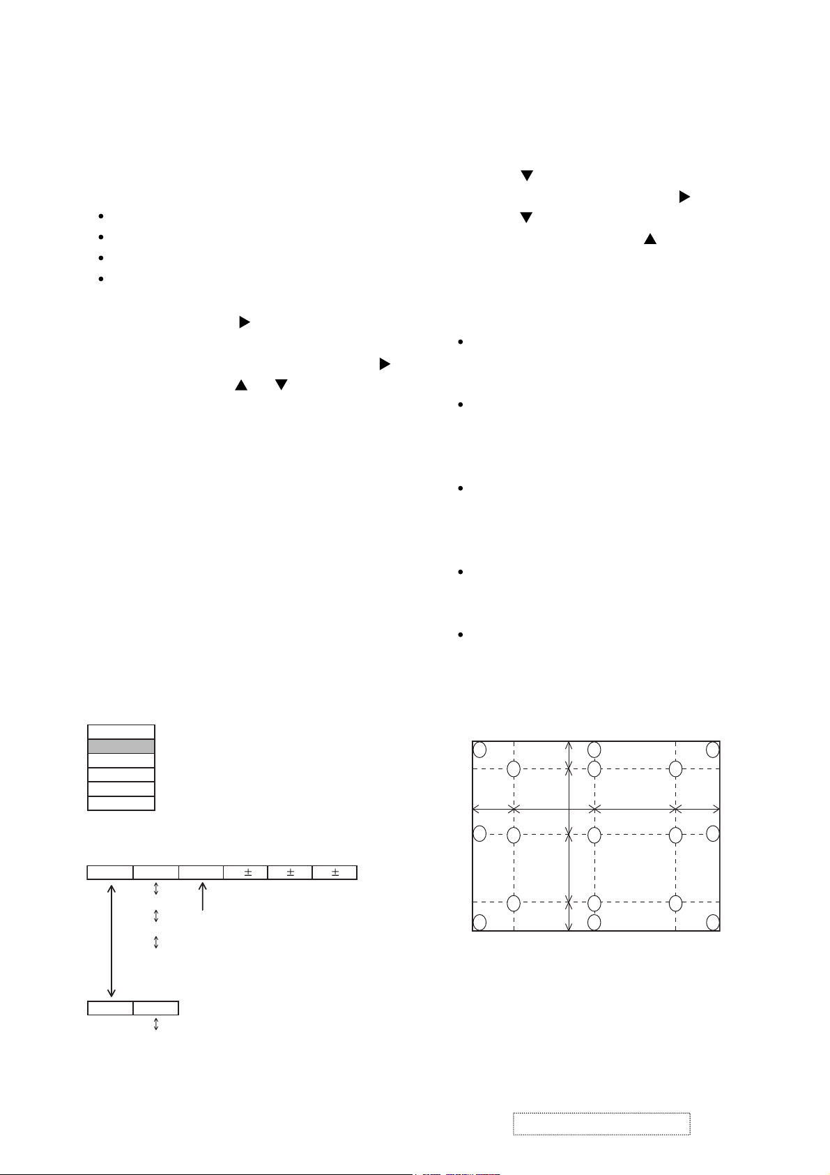
4-8 Color uniformity adjustment
Preparations
1.
Perform these adjustments after the white balance
adjustment described in Section 4-7.
2. Make a color uniformity adjustment for the follow-
ing four tones.
MIN tone (approx. 4% input signal)
MID-L tone (approx. 14% input signal)
MID-H tone (approx. 25% input signal)
MAX tone (approx. 57% input signal)
3. Place the cursor on [C.UNIF.] in the FACTORY
MENU and press the [ ] key. This displays the
Adjust Tone menu at the bottom of the screen.
To choose the tone to be adjusted, press the [ ]
key and then use the [ ] or [ ] key.
Select the major adjustment lattice point No.
and color, and then adjust them.
4. The major adjustment lattice point numbers (a
total of 17 points) corresponds to the major
adjustment lattice point positions in the diagram
on the right. The color uniformity of the entire
screen can be adjusted by adjusting the white
balance for each of the points starting in order
from the low numbers.
5. Adjustment point No.1 should not be adjusted,
because it controls the brightness of the entire
screen.
To temporarily turn correction off, place the
6.
cursor on [C.UNIF.] in the Adjust Tone menu and
press the [
] key. The ON/OFF menu appears.
Place the cursor on [ON] with the [ ] key and
press the [ ] key. To turn it on again, place the
cursor on [OFF] and press the [ ] key.
7. Although this adjustment can also be made
using internal signals, we will here use the
[ENTER] key on the Remote control transmitter
to select the following two signals.
Solid monochrome adjustment color (use G
color adjustment when a color differential
meter is used).
Solid white (use for adjustment other than
above).
8. Reset color-shading correction before adjust-
ment.
When 4 tones and all colors are to be reset,
place the cursor on [C.UNIF.] in the FACTORY
MENU, press the [RESET] key and select
[DEFAULT].
When only 1 tone is to be reset, place the
cursor on the tone to be reset, press the
[RESET] key and select [DEFAULT].
Single tone and monochrome resets cannot
be performed.
FACTORY MENU
VID-AD
C. UNIF.
DAC-P
GAMMA
STRIPE
OPTION
Adjust tone menu
C.UNIF
ON/OFF ON
MIN
MID-L
MID-H
MAX
OFF
No. 1 R 0
Major adjustment lattice point No.
G 0 B 0
Major adjustment lattice point position
14 12
H/6 H/3 H/3 H/6
10 11
15 17
V/6
6 4 8
V/3
2 1 3
V/3
7 5 9
V/6
13
16
ViewSonic Corporation
8
Confidential -Do Not Copy PJ452-2
Page 12

Adjustment procedure 1
(When a color differential meter is used)
1. First adjust [MID-L] tone [G:].
2. Select adjustment point [No.2][G:].
When the background is not [G] monochrome,
press the [ENTER] key on the Remote control
transmitter to change to solid [G] monochrome.
3. Measure the illumination at adjustment points
No. 2, No.3, No.10 and No.11.
The values should be:
No.2 = Y2 [lx] No.10 = Y10 [lx]
No.3 = Y3 [lx] No.11 = Y11 [lx]
4. No.2 and No.3 adjustment point have the aver-
age of Y2 and Y3.
Y2 = ( Y2 + Y3 ) / 2 ± 2 [%]
Y3 = ( Y2 + Y3 ) / 2 ± 2 [%]
5. No.10 and No.11 adjustment point have the
average of Y10 and Y11.
Y10 = ( Y10 + Y11 ) / 2 ± 2 [%]
Y11 = ( Y10 + Y11 ) / 2 ± 2 [%]
6. Then adjust [MID-L] tone [R] and [B].
When the background is [G] monochrome,
press the [ENTER] key on the Remote control
transmitter to change to solid white.
7. Measure the color coordinates of adjustment
point [No.1] and make a note of them.
Assume that they are x = x1, y = y1.
Note: When the CL-100 color and color differ-
ence meter is used, the [ ∆ ](delta) mode
is convenient. When adjustment point
[No.1] color coordinate has been
selected, set the slide switch on the side
to [∆ ](delta) while holding down the [F]
button on the front panel. The measure-
ment shown after this displays the devia-
tion from measurement point 1.
8. Measure the color coordinates of measurement
point [No.2] and adjust [No.2][R:] and [B:] so
that the coordinates are as follows.
x = x1 ± 0.005 , y = y1 ± 0.010
9. Similarly, measure adjustment points [No.3] to
[No.17] and adjust their color coordinates start-
ing in order from the small number points.
This completes adjustments required for [MIN].
Note: Since excessive correction may lead to a
correction data overview during internal
calculations, use the following values for
reference.
[No.2] to [No.5] ± 40 or less
[No.6] to [No.9] ± 50 or less
[No.10] to [No.13] ± 70 or less
[No.14] to [No.17] ± 120 or less
10. Then adjust [MIN] tone [G] so that the adjust-
ment data set two times as much as [MID-L]
tone [G].
This completes [G] color adjustments.
11. Then adjust [MIN] tone [R] and [B].
Select [No.2] [B:] and press the [ENTER] key
on the Remote control transmitter to change to
solid white.
12. Measure the color coordinates of adjustment
point [No.1] and make a note of them.
Assume that they are x = x1, y = y1.
13. Now measure the color coordinates of mea-
surement point [No.2] and adjust [No.2][R:] and
[B:] so that the coordinates are as follows.
x = x1 ± 0.005 , y = y1 ± 0.010 (Target)
x = x1 ± 0.020 , y = y1 ± 0.040
14. Similarly, measure adjustment points [No.3] to
[No.17] and adjust their color coordinates start-
ing in order from the small number points.
This completes [MIN] tone adjustments.
15. Now make similar adjustments for [MID-H] tone.
(Adjust [MID-H] tone [G] so that the adjustment
data set half as many as [MID-L] tone [G].)
16. Now make similar adjustments for [MAX] tone.
(Adjust [MAX] tone [G] so that the adjustment
data set half as many as [MID-L] tone [G].)
ViewSonic Corporation
9
Confidential -Do Not Copy PJ452-2
Page 13
Adjustment procedure 2
(visual inspection)
1. First adjust [MIN] tone [G:].
2. Select [No.2] [G:].
If the background is [G] monochrome, press the
[ENTER] key on the Remote control transmitter
to change to solid white.
3. View measurement point [No.2] and [No.3].
Lower the [G] color intensity only of the color
point whose [G] color is more intense than
measurement point [No.1].
4. View measurement point [No.10] and [No.11].
Lower the [G] color intensity only of the color
point whose [G] color is more intense than
measurement point [No.1], and raise the inten-
sity of the point whose color intensity is lower
than measurement point [No.1].
5. Now adjust the [MIN] tone for colors [R] and [B].
6. View measurement points [No.2], [No.3],
[No.10] and [No.11]. Adjust the [R] and [B] of
each measurement point so that they have the
same color as measurement point [No.1].
Adjustment technique:
First, adjust [B:] of the point whose color is to
be adjusted so that it approximates that of
[No.1]. If [R:] is low at this time, the image will
have cyan cast, in which case [R:] is increased.
On the other hand, if [R:] is excessive, the
image will have a magenta cast, in which case
[R:] is decreased.
Overall, a cyan cast makes it easy to see color
shading.
7. Next, view measurement points [No.4], [No.5],
[No.12], [No.13] and make similar adjustments.
Then adjust measurement points [No.6], [No.7],
8.
[No.8], [No.9], [No.14], [No.15], [No.16] and [No.17].
This completes the [MIN] tone adjustments.
9. Make similar another three tones as described
in steps 1 to 8 above.
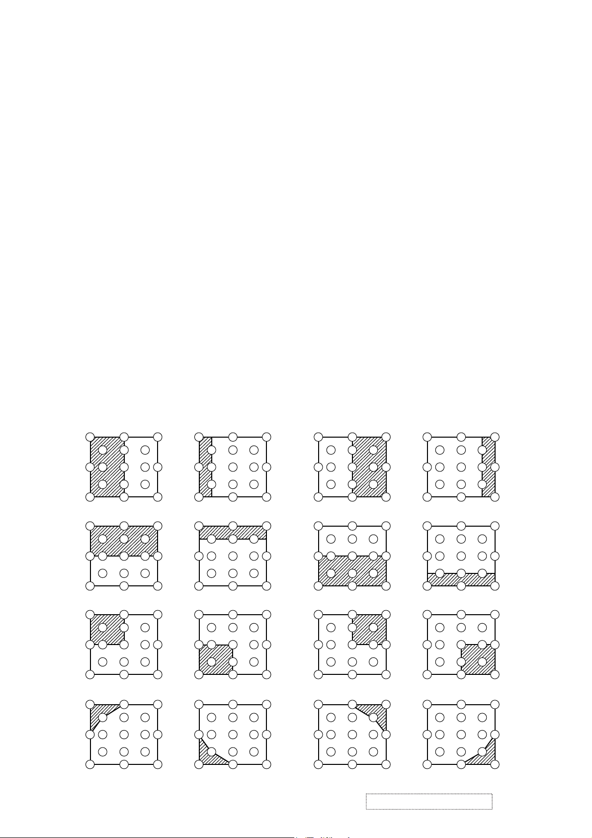
No. 2 deviation range No. 10 deviation range No. 3 deviation range No. 11 deviation range
14
10
15 13
12
6
2
7
4
1
5
16
8
3
11
9
17
14 12
6
2
10
7
15 13
4
1
5
16
8
3
11
9
17
14
10
15
12
6
4
2
1
5
7
13
16
8
3
11
9
17
14 12
6
2
10
7
15 13
16
4
8
1
3
11
5
9
17
No. 4 deviation range No. 12 deviation range No. 5 deviation range No. 13 deviation range
16
8
3 112
9
17
14 12
6
2
10
7
15 13
16
4
8
1
3
113 11210 1
9
5
17
7
15 13
1614 12
86 4 84
9
5
17
6
2
10 1
7
15 13
1614 12
3
11
9
5
17
14
10 1
15
12
6
4
5
7
13
No. 6 deviation range No. 7 deviation range No. 8 deviation range No. 9 deviation range
7
15 13
1614 12
86 4 84
3 11210 1
9
5
17
10 12
1614 12
6
3
11
9
5
7
1315
17
14
10
15
12
6
418
5
7
13
16
3 112
9
17
14 12
2
10
7
15
13
16
46
8
1 3 11
95
5
17
No. 14 deviation range No. 15 deviation range No. 16 deviation range No. 17 deviation range
1614 12
6
84 84
6
1614 12
14
12
6
4
16
8
14 12
46
16
8
10
5
7
15 13
ViewSonic Corporation
3
3 112 1
9
17
10 12
15
5
7
13
11
9
17
10
7
15
13
32
1
5
11
9
17
10
15
2
7
1 3511
9
5
13
17
Confidential -Do Not Copy PJ452-2
10
Page 14
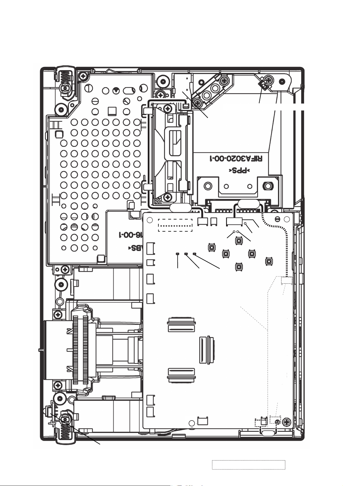
5. Troubleshooting
Check points
*Top view of the projector after the silver gilding over the lamp
house and black sheet on the main board are detached.
Thermal SW assembly(TSW)
PWB assembly SW
E801
E804
E301
E802
CNLC
E800
D303
(LAMP)
P501
E803
ESPL
CHSYM
D302
(TEMP)
D301
(Power)
PWB assembly I/O
P601
CNVD
EA05
CHCVM
CHSCM
EM02
PWB assembly REMOTE
ViewSonic Corporation
E807
E805
11
P701
PWB assembly MAIN
E302
E101
Confidential -Do Not Copy PJ452-2
E806
EM01
14
CNCO
Page 15
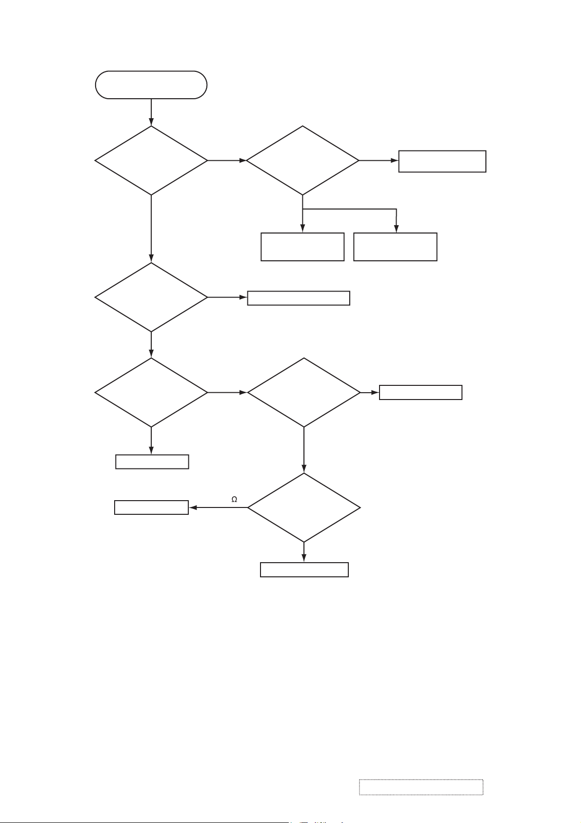
Power can not be turned on
Are
voltage input at
pins (1)(3)(5)(7) of E800
on the PWB assembly
Main at standby
mode?
YES
What is the state of
TEMP indicator D302?
Not light
What is the state of
LAMP indicator D303?
NO
(1): +0V
(3): +17V
(5): +6.6V
(7): +4.1V
Blinks
Blinks
Unplug
power cord and
disconnect TSW from the
power unit (circuit), then
measure resistance of
the cooled
TSW.
Short
Power unit (circuit)
Jump to * on the next page
Is the LAMP DOOR
set?
Open
Power unit (circuit)
NG
Thermal SW assembly
Fuse on the
Set the LAMP DOOR
(TSW)
Not light
PWB assembly Main
PWB assembly Main
Short (0 )
OK
Unplug
power cord and
disconnect cable CNLC,
then measure resistance
between pins (1)
and (2) of
CNLC.
Open
PWB assembly SW
ViewSonic Corporation
12
Confidential -Do Not Copy PJ452-2
Page 16
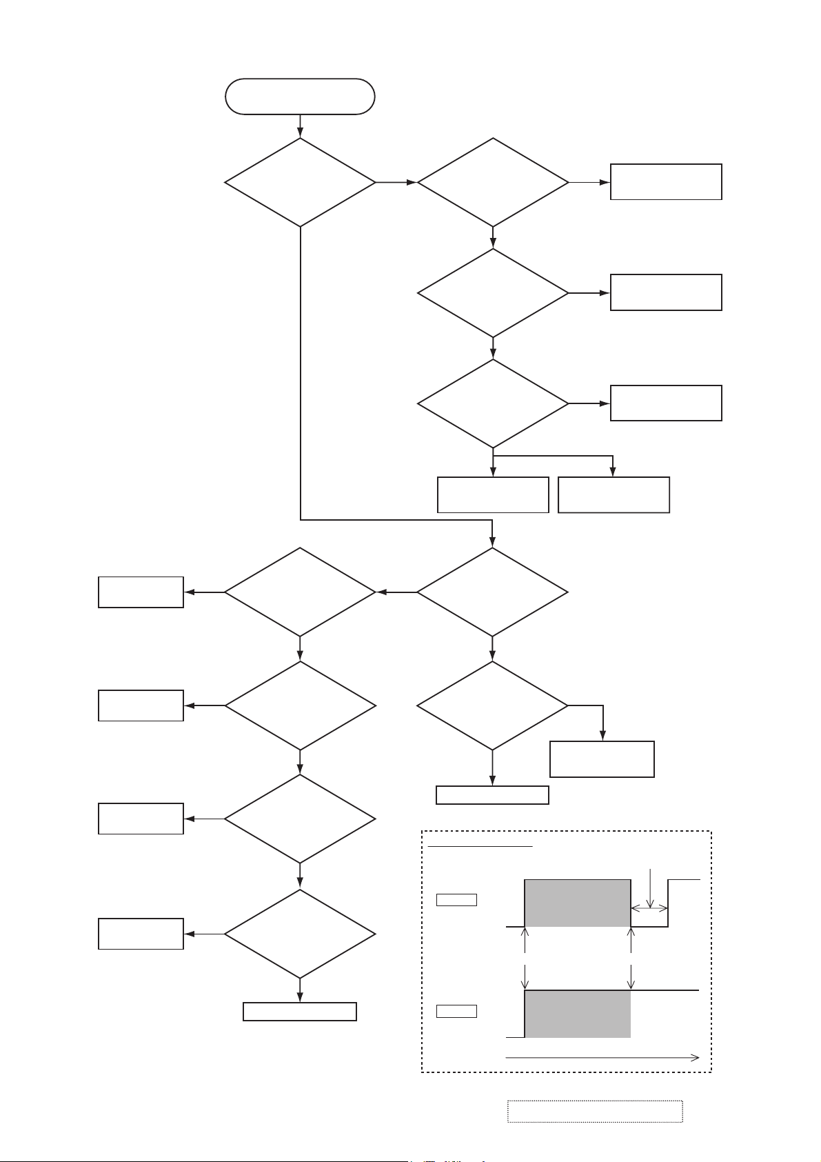
Lamp does not light
DC FAN
BM4515
NO(Failure)
What is the
state of LAMP indicator
D303 during operation?
Not light
Does
voltage of E806’s
1st pin drop to 0V
temporarily soon after projector
is powered up?
Light NG
Blinks
*
See Fig.1
Is the LAMP
installation correct?
YES
Change the lamp.
Does lamp light?
Not light
Is the
voltage at the
(1) of E804 on the PWB
assembly MAIN fixed to "L"
during warming-up?
NO
Power unit (ballast)
What is the state
of TEMP indicator D302?
Install the Lamp
Light
YES
"L" = 0V
Power unit (circuit)
PWB assembly MAIN
Lamp
DC FAN
D06T
DC FAN
TYF450L
DC FAN
TYF400L
NO(Failure)
NO(Failure)
NO(Failure)
YES(Normal)
Does
voltage of E801’s
1st pin drop to 0V
temporarily soon after projector
is powered up?
YES(Normal)
Does
voltage of E807’s
1st pin drop to 0V
temporarily soon after projector
is powered up?
YES(Normal)
Does
voltage of E802’s
1st pin drop to 0V
temporarily soon after projector
is powered up?
YES(Normal)
PWB assembly MAIN
See Fig.1
See Fig.1
See Fig.1
Not light
Is the voltage
at the (3) of E804 on
the PWB assembly MAIN
set to "L" during
warming-up?
YES
Power unit (ballast)
Fig.1 Waveform shape
H(2.5V)
Normal
0V
H(2.5V)
Failure
0V
NO
"L" = 0V
PWB assembly MAIN
about 1 sec.
On stand-by
Powered upAC on
On stand-by
ViewSonic Corporation
Time
Confidential -Do Not Copy PJ452-2
13
Page 17
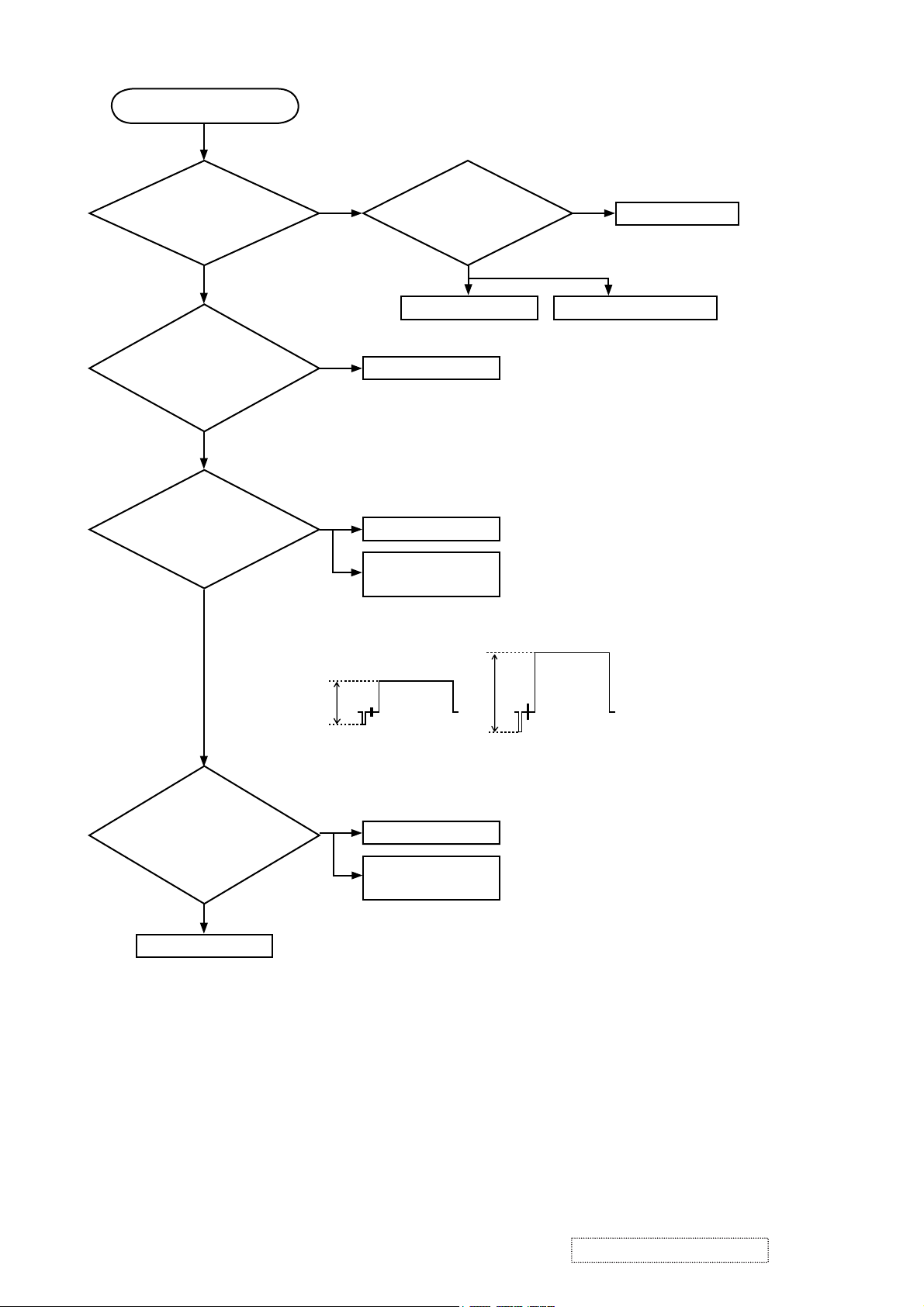
Picture is not displayed.
Are
the splash
screen and the user menu
displayed correctly?
YES
Are both of pictures
from RGB1 and RGB2 ports
displayed correctly?
YES
Observe
the video signal
voltage-waveform at the CHCVM.
Is it half amplitude of the
original?
YES
NO
NO
PWB assembly MAIN
NO
PWB assembly I/O
Confirm CNVD
Confirm
the LCD Panels
connection to the MAIN
NG
CPC30 connector
board.
OK
PWB assembly MAIN LCD/Lens prism assembly
connection
Observe
the s-video signal
voltage-waveforms at the
CHYSM and CHYCM. Are they half
amplitude of the originals?
YES
PWB assembly MAIN
Ex: Observed and original waveforms
A
0.5*A
Observed Original
(75ohm terminated)
NO
PWB assembly I/O
Confirm CNVD
connection
ViewSonic Corporation
14
Confidential -Do Not Copy PJ452-2
Page 18
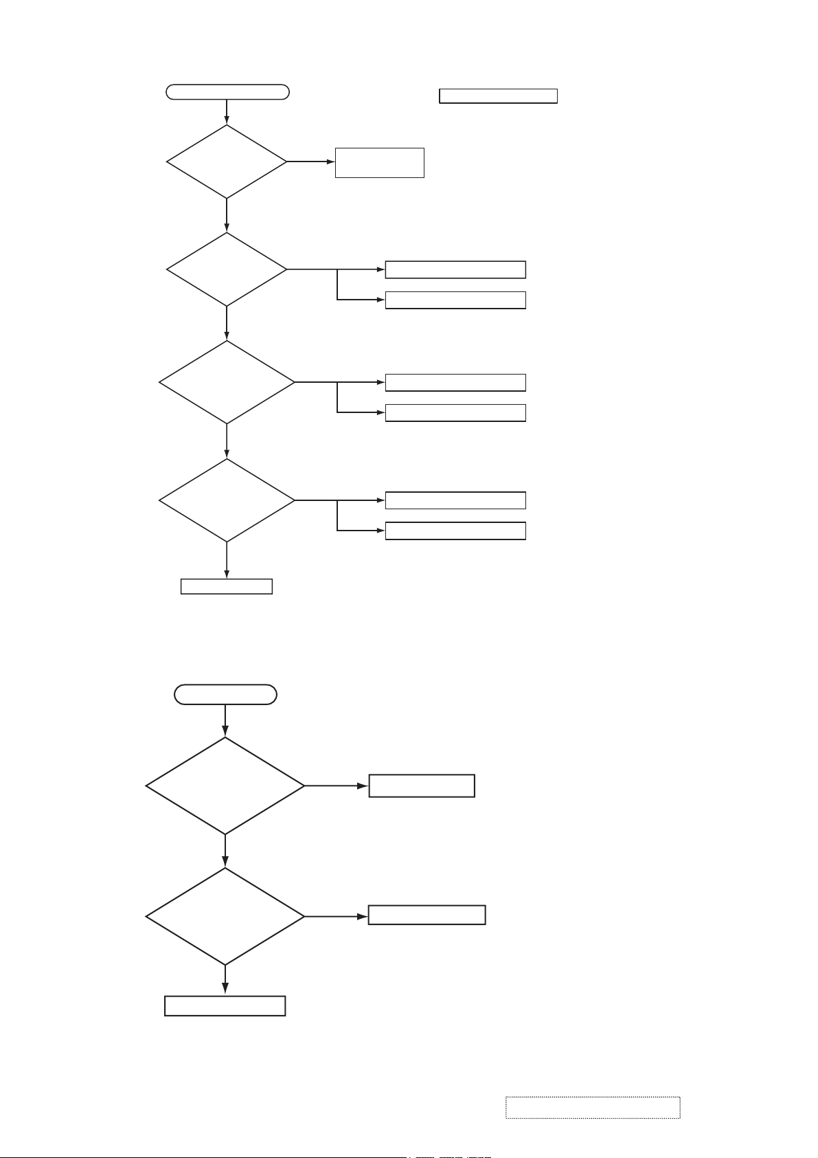
Can not control to RS-232C
Check the
RS-232C cable.
Are pins No. 2 and 3
crossed?
YES
Is the
proper voltage
supplied to the pin (1) of
EM01 of the I/O
board?
Are 5Vp-p
square waves
observed at the pin (3) of
E101 when commands are
transmitted from
PC?
Are
square waves
observed at the pin (2) of
EM01 when commands are
transmitted from
PC?
EM01(1): 5V
YES
YES
NO
NO
NO
YES
Use cross cable
Check the cable CNCO connection
The check after parts change
1. PC power supply OFF
2. Connection of cable
3. Projector starting
4. PC starting
*When not operating :
PC set up change of cable.
PWB assembly MAIN
PWB assembly I/O
Make sure PC set up
PWB assembly I/O
PC
NO
PWB assembly MAIN
No sound
Are
voltage input at pin
(1)(3)(5)(7) of the E800 on
the PWB assembly
MAIN?
YES
(1): +13.2V
(3): +17V
(5): +6.6V
(7): +4.1V
Turn off
the projector and
disconnect the speaker
cable from ESPL. Measure
the resistance of
the speaker
.
NO
about 8Ω
Power unit (circuit)
PWB assembly MAIN
ViewSonic Corporation
0Ω or infinity
Speaker
Confidential -Do Not Copy PJ452-2
15
Page 19
6. Service points
6-1 Lead free solder [CAUTION]
This product uses lead free solder (unleaded) to help preserve the environment. Please read these
instructions before attempting any soldering work.
CAUTION
Always wear safety glasses to prevent fumes or molten solder from getting into the eyes. Lead free solder
can splatter at high temperatures (600˚C).
Lead free solder indicator
Printed circuit boards using lead free solder are engraved with an "F" or "LF".
Properties of lead free solder
The melting point of lead free solder is 40-50˚C higher than leaded solder.
Servicing solder
Solder with an alloy composition of Sn-3.0Ag-0.5Cu or Sn-0.7Cu is recommended.
Although servicing with leaded solder is possible, there are a few precautions that have to be taken. (Not
taking these precautions may cause the solder to not harden properly, and lead to consequent malfunctions.)
Precautions when using leaded solder
Remove all lead free solder from soldered joints when replacing components.
If leaded solder should be added to existing lead free joints, mix in the leaded solder thoroughly after the
lead free solder has been completely melted (do not apply the soldering iron without solder).
Servicing soldering iron
A soldering iron with a temperature setting capability (temperature control function) is recommended.
The melting point of lead free solder is higher than leaded solder. Use a soldering iron that maintains a high
stable temperature (large heat capacity), and that allows temperature adjustment according to the part being
serviced, to avoid poor servicing performance.
Recommended soldering iron:
Soldering iron with temperature control function (temperature range: 320-450˚C)
Recommended temperature range per part:
Part Soldering iron temperature
Mounting (chips) on mounted PCB 320˚C±30˚C
Mounting (chips) on empty PCB 380˚C±30˚C
Chassis, metallic shield, etc. 420˚C±30˚C
The PWB assembly which has used lead free solder
(1) PWB assembly MAIN
(2) PWB assembly REMOTE
(3) PWB assembly SW
(4) POWER UNIT (BALLAST)
(5) POWER UNIT (CIRCUIT)
(6) PWB assembly I/O
ViewSonic Corporation
16
Confidential -Do Not Copy PJ452-2
Page 20
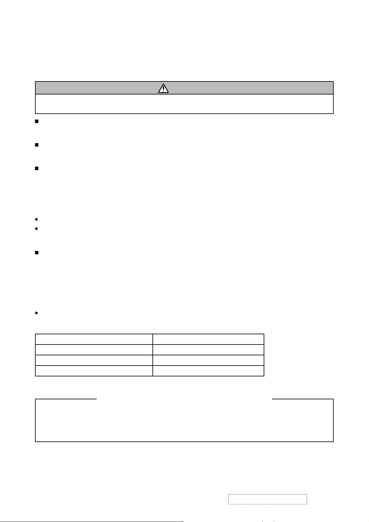
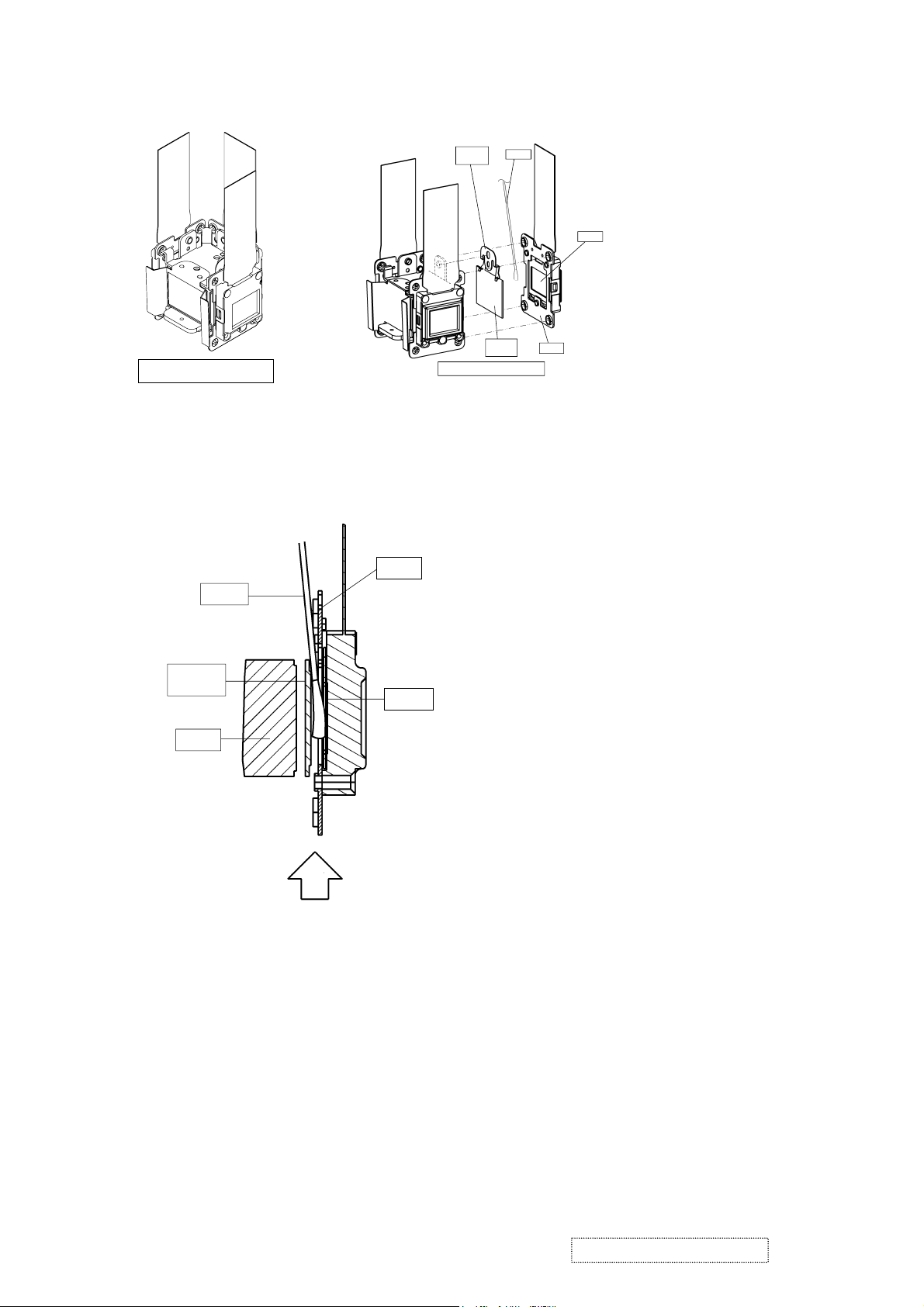
6-2 Replacing The LCD/PRISM assembly
You should not replace separately the parts of the LCD/PRISM assembly. In case of a failure in any parts of
LCD/PRISM assembly, replace the whole LCD/PRISM assembly.
Do not disassemble the unit
because replacement of separate
parts is not possible.
LCD/PRISM ASSY
6-3 Cleaning up dust from panels and optical filters
WARNING
Wear sunglasses to protect your eyes when you maintain the projector with its lamp on.
1. Preparation
Please prepare cleaning tools and materials as follows. And prepare relatively clean room not to work in
additional dust, while removing operation.
(1) Swab for cleaning : P#: NX08061, "Cotton stick L147"
(2) Air duster (Dust blower, spray can)
(3) Vacuum cleaner
2. Disassemble and open the maintenance hole.
(1) Turn off the projector, and unplug the power cord.
(2) Remove the top cover, according to the notice 1 of chapter 8.
(3) Remove the PWB assembly MAIN, according to the notice-2 of the chapter 8.
(4) Remove the Panel Cover.
Connect 9 cables
Remove Panel Cover
Flexible cables of LCD panels
PWB assembly MAIN
(5) Attach the PWB assembly MAIN in original place, and connect 9 cables indicated in the diagram
above. Note that flexible cables of LCD panels should come to the upper portion of PWB assembly
MAIN, but don’t connect them to the connectors. Make sure that flexible cables’ terminals don’t touch
to any other parts during maintenance, especially when the projector is turned on.
ViewSonic Corporation
17
Confidential -Do Not Copy PJ452-2
Page 21
3. Maintenance point
Filter
Stopper
Swab
Each color part has same
construction.
By using swab and air duster,
Panel
you can easily remove dust
from panel and optical filter.
The diagram shows the LCD/
PRISM block structure.
Actually, it is not allowed to
disassemble the block.
Actual formation
Optical
Filter
Separated formation
Plate
4. Cleaning the LCD panels and optical filters
(1) Turn on the projector and lit on the lamp.
(2) By using swab and air duster, remove the dust. Insert swab through holes of MAIN board, and wipe
LCD Panels. Focusing dust makes you check the dust on screen.
Plate
Swab
• While removing the dust, separated dust
will be blown off by air cooling system.
• Please pay attention not to damage LCD
panels and optical filters.
Optical
Filter
Panel
Prism
Air
5. Re-assembly
(1) Turn off the projector and remove the PWB assembly MAIN.
(2) Set the
Panel cover
so that stress is not put on flexible cables of LCD panels.
(3) Attach the PWB assembly MAIN in place, and connect cables to connectors of it.
(4) Re-assemble the projector.
(5)
While re-assembling, please clean the air filter and filter cover by using vacuum cleaner.
ViewSonic Corporation
18
Confidential -Do Not Copy PJ452-2
Page 22
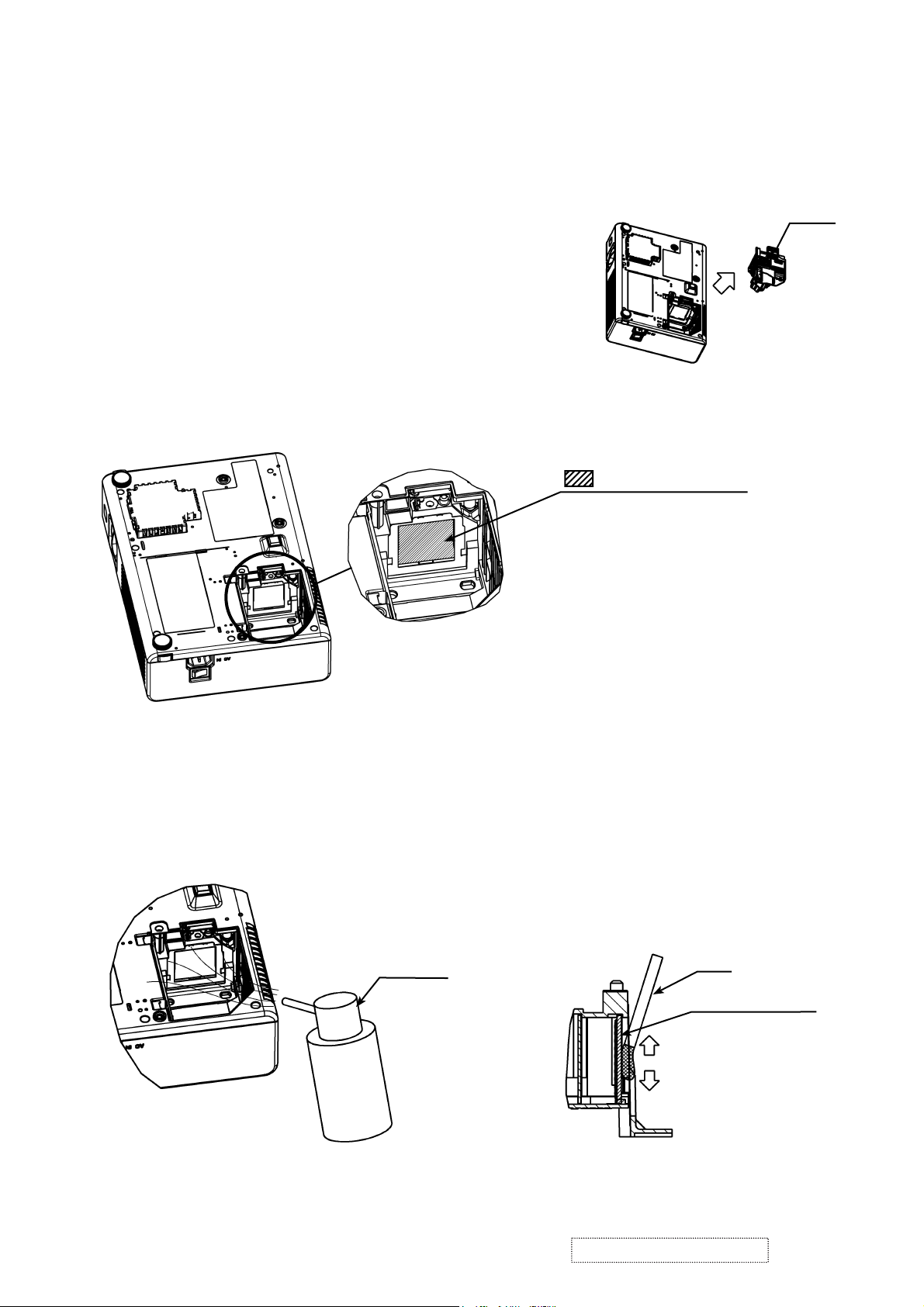
6-4 Cleaning up dust from multilens
1. Preparation
Please prepare cleaning tools and materials as follows.
(1) Air duster (Dust blower, spray can)
(2) Swab for cleaning ; P#NX08061, ”Cotton stick L147”
(3) Vacuum cleaner
2. Remove the lamp door and the lamp unit assembly.
(1) Turn off the projector, and unplug the power cord.
(2) Remove the lamp door and lamp unit assembly accord-
ing to the description of chapter “Replacing the LAMP”.
3. Maintenance point
LAMP
multilens surface
Removeing the lamp shows the
part multilens positioned vertically.
Wipe the whole of the multilens
surface using the sweb.
CAUION :
Use special caution not to damage
the multilens
4. Cleaning the multilens
(1) By using the air duster, remove the dust on multilens.
(2) Wipe the surface of multilens by using swab.
By using the air duster, remove the dust in multilens
CAUION :
Use special caution not
to scratch the multilens
Air duster
5. Attach the lamp door and the lamp unit assembly.
Attach the lamp door and the lamp unit assembly accoding the description of “Replacing the LAMP”.
CAUION :
Use special caution not
to scratch the multilens
swab
multilens surface
Cross section
of multilens
ViewSonic Corporation
19
Confidential -Do Not Copy PJ452-2
Page 23
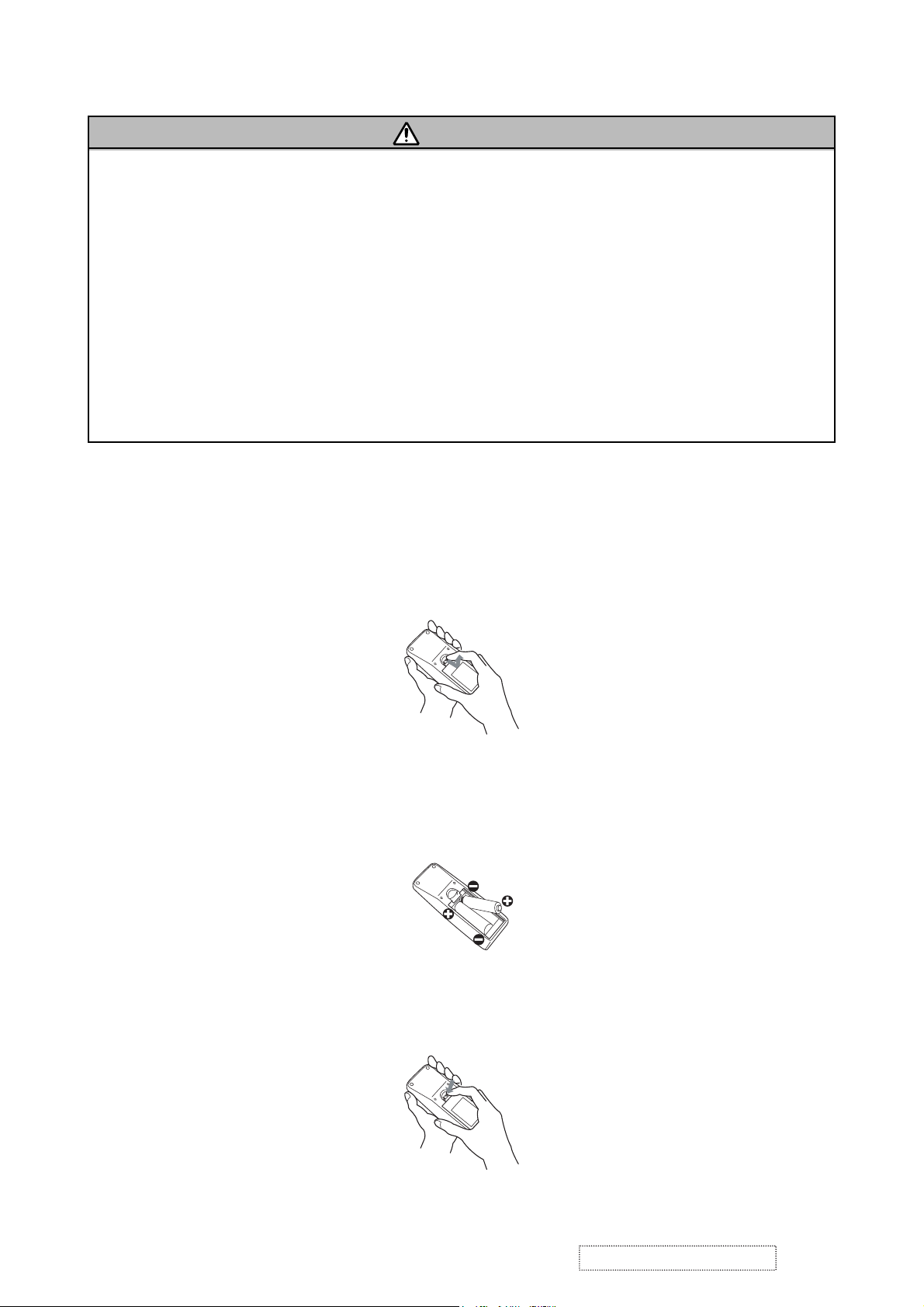
6-5 Putting batteries
WARNING
Always handle the batteries with care and use them only as directed. Improper use may result in battery
explosion, cracking or leakage, which could result in fi re, injury and/or pollution of the surrounding environ-
ment.
• Be sure to use only the batteries specifi ed. Do not use batteries of different types at the same time. Do
not mix a new battery with used one.
• Make sure the plus and minus terminals are correctly aligned when loading a battery.
• Keep a battery away from children and pets.
• Do not recharge, short circuit, solder or disassemble a battery.
• Do not allow a battery in a fi re or water. Keep batteries in a dark, cool and dry place.
• Do not give the battery a physical impact.
• If you observe a leakage of a battery, wipe out the flower and then replace a battery. If the flower
adheres your body or clothes, rinse well with water immediately.
• Obey the local laws on disposing a battery.
To use the remote control, please load the batteries. Whenever the remote control starts to malfunction,
replace the batteries. If you won’t use the remote control for an extended period, remove the batteries from
the remote control and store them in a safe place.
1. Remove the battery cover.
Slide back and remove the battery cover in the direction of the arrow.
2. Take old batteries out and/or put new batteries in.
When putting in batteries, align and insert the two AA batteries according to their plus and minus terminals
as indicated in the remote control.
3. Close the battery cover.
Replace the battery cover in the direction of the arrow and snap it back into place.
ViewSonic Corporation
20
Confidential -Do Not Copy PJ452-2
Page 24

6-6 Air filter
WARNING
●
Before caring, make sure the power switch is off and the power cable is not plugged in, then allow the
projector to cool sufficiently. The care in a high temperature state of the projector could cause an electric
shock, a burn and/or malfunction to the projector.
●Use only the air filter of the specified type. Do not use the projector with the air filter and the filter cover
removed. Do not remove the filter cover and the air filter in a smoky or dusty place. It could result in a fire
and/or malfunction to the projector.
●The air filter should be cleaned periodically. If the air filter becomes clogged by dust or the like, internal
temperatures rise and could cause a fire, a burn and/or malfunction to the projector.
CAUTION
●Please be careful for the projector not to fall. While the projector is placed lens-side up, hold the projector.
If the air filter becomes clogged by dust or the like, internal temperatures rise and could cause a fire, a burn
and/or malfunction to the projector.When the indicators or a message prompts you to clean the air filter,
clean the air filter as soon as possible. Please check and clean the air filter periodically, even if there is no
message.
Please replace the air filter when it is damaged or too soiled. Preparation of a new air filter is recommended.
When you replace the lamp, please replace the air filter. An air filter of specified type will come together with
a replacement lamp for this projector.
1. Turn the projector off, and unplug the power cord. Allow the lamp to cool sufficiently.
2. When the projector is suspended from the ceiling, apply the vacuum cleaner to and around the filter cover
first, to prevent of dust or the like.
3. Disconnect all the connectors and adapters that were connected to the projector’s ports. Then slowly turn
the projector so that the lens-side is facing up. While the projector is placed lens-side up, hold the projector.
4. Remove the filter cover and the air filter. Then slowly turn the projector, so that the bottom is facing up.
Usual filter cover
(1) Remove the filter cover.
Hold the knobs while pulling out it.
(2) Remove the air filter.
Hold the knob while pulling out it.
Filter cover for bottom-up use
(1) Remove the filter cover.
Hold the knob while pulling out it.
(2) Slowly turn the projector bottom up.
(3) Remove the air filter from the filter cover.
Air filter
(3) Slowly turn the projector bottom up.
5. Apply a vacuum cleaner to the vent of the projector for the air filter, the air filter and filter cover.
Please replace the air filter when it is damaged or too soiled.
ViewSonic Corporation
21
Confidential -Do Not Copy PJ452-2
Filter cover
Page 25

6. Position the air filter and filter cover into place.
“PUSH” mark
(1) Set an air filter into place.
Push the points of “PUSH” mark.
(Usual filter cover)
(Filter cover for bot-
tom-up use)
(2) Interlocking the tabs, snap the
cover into place.
Tabs
Tabs
7. Please reposition and reconnect the projector, to return as before.
Then turn the projector on.
8. Reset the filter time using the FILTER TIME function in the OPTION menu.
(1) Press the MENU button to display a menu.
When the EASY MENU has appeared, please skip the next step (2).
(2) Point at the “OPTION” in the left column of the menu using ▼/▲ button, then press the ► button.
(3) Point at the ”FILTER TIME” using ▼/▲ button, then press the ► button. A dialog will appear.
(4) Press the ▲ button to select “RESET” on the dialog. It performs resetting the filter time.
NOTE
• Please replace the air filter when it is damaged or too soiled, and also when you replace the lamp.
• Please reset the filter time only when you have cleaned or replaced the air filter, for a suitable indication
about the air filter.
• The projector may display the message such as “CHECK THE AIR FLOW” or turn off the projector, to
prevent the internal heat level rising.
About the filter cover for bottom-up use
When the projector is installed bottom up, please use the accessory fi lter cover for bottom-up use. It is higher
than usual fi lter cover, to keep the space for intake ventilation. Please change in the following procedure.
1. Disconnect all the connectors and adapters that were connected to the projector’s ports. Then slowly turn
the projector so that the lens-side is facing up. Please be careful for a projector not to fall. While the
projector is placed lens-side up, hold the projector.
2. Remove the fi lter cover and the air fi lter. Hold the knobs while pulling out it.
3. Slowly turn the projector so that the bottom is facing up.
4. Set a new or cleaned air fi lter to the fi lter cover for bottom-up use. Make the claws slide along the rail, and
set the air fi lter into place.
Claws
Rail of air fi lter
Filter cover for bottom-up use
5. Interlocking the tabs, snap the fi lter cover for bottom-up use into place.
Air fi lter (New or cleaned)
ViewSonic Corporation
22
Confidential -Do Not Copy PJ452-2
Page 26

6-7 Lamp
WARNING
HIGH VOLTAGE HIGH TEMPERATURE HIGH PRESSURE
• The projector uses a high-pressure mercury glass lamp. The lamp can break with a loud bang, or burn
out, if jolted or scratched, handled while hot, or worn over time. Note that each lamp has a different lifetime, and some may burst or burn out soon after you start using them. In addition, when the bulb bursts, it
is possible for shards of glass to fly into the lamp housing, and for gas containing mercury to escape from
the projector’s vent holes.
● About disposal of a lamp • This product contains a mercury lamp; do not put in trash. Dispose of in
accord with environmental laws.
For lamp recycling, go to www.lamprecycle.org. (in the US)
For product disposal, contact your local government agency or www.eiae.org (in the US) or www.epsc.ca
(in Canada).
• If the lamp should break (it will make a loud bang when it does), unplug the power cord from
the outlet. Note that shards of glass could damage the projector’s internals, or cause injury
Disconnect
the plug
from the
power
outlet
during handling.
• If the lamp should break (it will make a loud bang when it does), ventilate the room well, and
make sure not to breathe the gas that comes out of the projector vents, or get it in your eyes
or mouth.
• Before replacing the lamp, turn the projector off and unplug the power cord, then wait at
least 45 minutes for the lamp to cool sufficiently. Handling the lamp while hot can cause
burns, as well as damaging the lamp.
• Never unscrew except the appointed (marked by an arrow) screws.
• Do not open the lamp cover while the projector is suspended from above. This is dangerous, since if the lamp’s bulb has broken, the shards will fall out when the cover is opened. In
addition, working in high places is dangerous.
• Do not use the projector with the lamp cover removed. At the lamp replacing, make sure
that the screws are screwed in firmly. Loose screws could result in damage or injury.
• Use only the lamp of the specified type.
• If the lamp breaks soon after the first time it is used, it is possible that there are electrical
problems elsewhere besides the lamp.
• Handle with care: jolting or scratching could cause the lamp bulb to burst during use.
• Using the lamp for long periods of time could cause it dark, not to light up or to burst. When
the pictures appear dark, or when the color tone is poor, please replace the lamp as soon as
possible. Do not use old (used) lamps; this is a cause of breakage.
ViewSonic Corporation
23
Confidential -Do Not Copy PJ452-2
Page 27

Replace the Lamp
A lamp has a Þ nite product life. Using the lamp for long periods of time could cause the pictures darker or the
color tone poor. Note that each lamp has a different lifetime, and some may burst or burn out soon after you
start using them. Preparation of a new lamp and early replacement are recommended.
1. Turn the projector off, and unplug the power cord. Allow the lamp to cool for at least 45 minutes.
2. Prepare a new lamp.
3. After making sure that the projector has cooled adequately, slowly turn
Claws of lamp cover
over the projector, so that the bottom is facing up.
4. Please loosen the screw (marked by arrow). Then, unhook the claws of the
lamp cover and remove the lamp cover.
5. Loosen the 2 screws (marked by arrow) of the lamp, and slowly pick up
the lamp by the handles.
Screw marked by arrow
6. Insert the new lamp, and retighten Þ rmly two screws that are loosened in
the previous process to lock it in place.
7. Interlocking the 2 tabs of the lamp cover to the projector, position the
lamp cover on the projector, and push the center point of two claws to
fix the lamp cover. Then retighten firmly the screw of the lamp cover.
8. Slowly turn the projector so that the top is facing up.
9. Turn the projector on and reset the lamp time using the LAMP TIME
function in the OPTION menu
(1) Press the MENU button to display a menu. Only when the EASY MENU
Screws marked
by arrow
Center
point
of claws
Tabs
has appeared, please perform the next step (2).
(2) Point at the “Go To Advance Menu …” in the menu using / button,
then press the button.
(3) Point at the “OPTION” in the left column of the menu using / button, then press the button.
(4) Point at the ”LAMP TIME” using / button, then press the button. A dialog will appear.
(5) Press the button to select “RESET” on the dialog. It performs resetting the lamp time.
NOTE
•Please reset the lamp time only when you have replaced the lamp, for a suitable indication about the lamp.
ViewSonic Corporation
24
Confidential -Do Not Copy PJ452-2
Page 28

6-8 Other care
WARNING
Do not take care of the projector during use or immediately after use. Handling while the projector is in a high
temperature could cause a burn and/or malfunction to the projector. Before operating, make sure that the power
switch is off, that the power cord is not plugged in, and that the projector is cool adequately.
Avoid wetting the projector or inserting liquids in the projector. It could result in a fi re, an electric shock,
and/or malfunction to the projector.
• Don’t put a container containing water , cleaner or chemicals near the projector.
• Don’t use aerosols or sprays.
CAUTION
Please take right care of the projector according to the following. Incorrect care could cause not only an
injury but adverse influence such as discoloration, peeling paint, etc.
• Do not use cleaner or chemicals other than those listed below.
• Do not polish or wipe with hard objects.
Inside of the projector
In order to ensure the safe use of the projector, it is needed to clean and inspect the projector about once
every year.
Caring for the lens
If the lens is flawed, soiled or fogged, it could cause deterioration of display quality. Please take care of the
lens, being cautious of the handling.
1. Turn the projector off, and unplug the power cord. Allow the projector to cool sufficiently.
2. After making sure that the projector is cool adequately, lightly wipe the lens with a commercially available
lens-cleaning wipe. Do not touch the lens directly with your hand.
Caring for the cabinet and remote control
Incorrect care could have adverse influence such as discoloration, peeling paint, etc.
1. Turn the projector off, and unplug the power cord. Allow the projector to cool sufficiently.
2. After making sure that the projector is cool adequately, lightly wipe with gauze or a soft cloth.
If soiling is severe, dip soft cloth in water or a neutral cleaner dilute in water, and wipe lightly after wringing
well. Then, wipe lightly with a soft, dry cloth.
ViewSonic Corporation
25
Confidential -Do Not Copy PJ452-2
Page 29

6-9 Notice of AUTO adjustment
Use of AUTO adjustment with the image through RGB input optimizes V_POSI, H_POSI, H_SIZE and
H_PHASE automatically.
In case that projected image has dark tone around its peripheral, AUTO operation sometimes makes artifacts
in the image, shifts capture area and so on. Those failures are caused by period of image data is not exactly
distinguished to period of blanking on signal processing.
To avoid such phenomena, AUTO function should be used with the full size picture that has bright tone on its
peripheral.
Image when AUTO operates correctly
Note
1) The phenomenon at the failure of AUTO adjustment depends on resolution of input source, scene of pic-
ture etc.
2) There is no failure above in AUTO with video source through VIDEO and S-VIDEO ports. The reason is why
recognition of input signal’s standard does not need to search the capture range from input signal itself.
Image when AUTO fails.
Noting image of top or bottom lines.
Shift of the image to East or West.
Artifacts on image. Etc.
ViewSonic Corporation
26
Confidential -Do Not Copy PJ452-2
Page 30

6-10 Related Messages
When the unit's power is on, messages such as those shown below may be displayed. When any such
message is displayed on the screen, please respond as described below.
Although these messages will be automatically disappeared around several minutes, it will be reappeared
every time the power is turned on.
Message Description
NO INPUT IS DETECTED
ON ***
SYNC IS OUT OF RANGE
ON *** fH *****kHz fV *****Hz
CHECK THE AIR FLOW
REMINDER
*** HRS PASSED AFTER THE
LAST FILTER CHECK.
FILTER MAINTENANCE IS
ESSENTIAL
TO REMOVE WARNING MESSAGE,
RESET FILTER TIMER.
SEE MANUAL FURTHER INFO.
There is no input signal.
Please confirm the signal input connection, and the status of the signal
source.
The horizontal or vertical wavelength of the inputted signal is outside
of the response parameters of this unit.
Please confi rm the specs for the projector or the signal source specs.
The internal portion temperature is rising.
Please turn the power OFF, and allow the unit to cool down at least 20
minutes. After having confi rmed the following
items, please turn the power ON again.
• Is there blockage of the air passage aperture?
• Is the air fi lter dirty?
• Does the peripheral temperature exceed 35°C?
• If the same indication is displayed after the treatment, please set the HIGH
at the FAN SPEED of the item SERVICE of the OPTION menu.
A note of precaution when cleaning the air fi lter.
Please immediately turn the power OFF, and clean or change the air fi lter
by referring to the “Air Filter” section of this manual. After you have cleaned
or changed the air fi lter, please be sure to reset the fi lter timer.
ViewSonic Corporation
27
Confidential -Do Not Copy PJ452-2
Page 31

6-11 Regarding the indicator lamps
Lighting and flashing of the POWER indicator, the LAMP indicator, and the TEMP indicator have the meanings as described in the table below. Please respond in accordance with the instructions with in the table.
POWER
indicator
Lighting
In Orange
Blinking
In Green
Lighting
In Green
Blinking
In Orange
Blinking
In Red
Blinking
In Red
or
Lighting
In Red
Blinking
In Red
or
Lighting
In Red
Blinking
In Red
or
Lighting
In Red
Blinking
In Red
or
Lighting
In Red
Lighting
In Green
Lighting
In Green
LAMP
indicator
Turned
off
Turned
off
Turned
off
Turned
off
(discretionary)
Lighting
In Red
Blinking
In Red
Turned
off
Turned
off
blinking in Red
Simultaneous
blinking in Red
indicator
Alternative
TEMP
Turned
off
Turned
off
Turned
off
Turned
off
(discretionary)
Turned
off
Turned
off
Blinking
In Red
Lighting
In Red
Description
The projector is in a standby state.
The projector is warming up.
Please wait.
The projector is in an on state.
Ordinary operations may be performed.
The projector is cooling down.
Please wait.
The projector is cooling down. A certain error has been detected.
Please wait until the POWER indicator finishes blink, and then perform the proper
response measure using the item descriptions below as reference.
The lamp does not light, and there is a possibility that interior portion has
become heated.
Please turn the power off, and allow the projector to cool down at least 20 minutes.
After the projector has sufficiently cooled down, please make confirmation of the
following items, and then turn the power on again.
• Is there blockage of the air passage aperture?
• Is the air fi lter dirty?
• Does the peripheral temperature exceed 35°C?
If the same indication is displayed after the remedy, please change the lamp by
referring to the section "Lamp"
The lamp cover has not been properly fi xed (attached).
Please turn the power off, and allow the projector to cool down at least 45 minutes.
After the projector has sufficiently cooled down, please make confirmation of the
attachment state of the lamp cover. After performing any needed maintenance, turn the
power on again.
The cooling fan is not operating.
Please turn the power off, and allow the projector to cool down at least 20 minutes.
After the projector has sufficiently cooled down, please make confirmation that no
foreign matter has become caught in the fan, etc. and then turn the power on again.
If the same indication is displayed after the remedy, please replace a fan.
There is a possibility that the interior portion has become heated.
Please turn the power off, and allow the projector to cool down at least 20 minutes.
After the projector has sufficiently cooled down, please make confirmation of the
following items, and then turn the power on again.
• Is there blockage of the air passage aperture?
• Is the air fi lter dirty?
• Does the peripheral temperature exceed 35°C?
If the same indication is displayed after the remedy, please set the HIGH at the FAN
SPEED of the item SERVICE of the OPTION menu.
There is a possibility that the interior portion has become overcooled.
Please use the projector within the usage temperature parameters (5°C to 35°C). After
the remedy, resent the power to ON.
If the same indication is displayed after the remedy, please make sure the wire
connection of the connectors E301 and E302 on the PWB assembly MAIN.
It is time to clean the air fi lter.
Please immediately turn the power off, and clean or change the air fi lter referring to the
section "Air Filter". After cleaning or changing the air fi lter, please be sure to reset the
fi lter timer. After the remedy, reset the power to ON.
If the same indication is displayed after the remedy, please make sure that the panel
duct assembly is assembled correctly. If it still does not recover, replace a cooling fan,
especially the dc fan for the blue LCD panel.
NOTE •
When the interior portion has become overheated, for safety purposes, the power source is automati-
cally turned off, and the indicator lamps may also be turned off. In such a case, press the “ ” (OFF) side of the
power switch, and wait at least 45 minutes. After the projector has suffi ciently cooled down, please make con-
fi rmation of the attachment state of the lamp and lamp cover, and then turn the power on again.
ViewSonic Corporation
28
Confidential -Do Not Copy PJ452-2
Page 32

6-12 HIDDEN SERVICE MENU
To display the OSD for “HIDDEN SERVICE MENU” set up.
By the control panel By the remote control
1. Display the Advance menu by
the “MENU” button.(If EASY
MENU appears, choose “Go to
Advance menu” to display
ADVANCE MENU.)
2. Select the “OPTION” on the
menu.
3. Continue press the button [
fi rst, then press the button [ ]
together with “INPUT”, and hold
for 3 seconds.
1. Display the menu by the
“MENU” button. (If EASY
MENU appears, choose “Go to
Advance menu” to display
ADVANCE MENU.)
2. Select the “OPTION” on the menu.
3. Press the “MAGNIFY OFF”
]
button.
Next hold the “MAGNIFY OFF”
button for 3 seconds.
SOFT RESET
If this is executed, all of the user data is initialized. Never use it when not required.
6-13 RUN TIME window
Set operating time display method (accumulated lamp time display method)
1. Select “ OPTION” from the Advance menu, then place the cursor on the “LAMP TIME”.
2. Press the [ ], [ENTER] or [RESET] button.
3. Press the [Reset] button once, then press [KEYSTONE] button of the remote control for 3 seconds or
more to display the screen shown below. (The menu will close after 10 seconds if there are no further operations.)
4. Use [ ] and [ ] buttons to select the usage status number. (The usage status is as shown below.)
Usage status number
0 ..... Total usage status
1 ..... Current usage status
2 ..... Usage status before first reset
3 ..... Usage status before second reset
9 ..... Usage status before eighth reset
10..... Total time(hrs.) the projector has been used in both stand-by
RUN TIME
On 12
OFF 11
||
and operation
1234
No.1
Time
Number of times on
Number of times off
Usage status number (See below)
ViewSonic Corporation
29
Confidential -Do Not Copy PJ452-2
Page 33

7. Wiring diagram
Secure the lamp house, and fix
two long screws in the locations
indicated on the diagram.
Important
Secure the lens, fix two screws in
the locations indicated on the dia-
gram, and put the foam ring on.
Operations with instructions are areas that have
implications with laws/standards. It is possible to
be in violation of these laws/standards in the
case that these operations are not carried out
according to the instructions. Assemble accord-
ing to the operation instructions.
a2
a3
a1
Affix the fan, and attach black tape.
Fix two screws in the locations indicated
on the diagram. Note that washers should
be inserted underneath the screws.
speaker
First, affix the optical engine
by using two screws in the lo-
cations (a1) (a2) indicated on
the diagram, then fix one
screw as indicated in the up-
per part of the diagram (a3).
Wiring diagram 1
ViewSonic Corporation
First, affix the small iron part
in the locations indicated on
the diagram, then attach the
silver gilding.
Attach the right and left ele-
vator buttons, and attach the
springs on them.
Affix the speaker in the location indicated on the diagram,
and secure the wires into the slits indicated in the diagram.
Attach the terminal panel to the bottom case, and secure
two screws in the locations indicated on the diagram.
Attach the black insula-
tion sheet to the surface
of the silver gilding.
Confidential -Do Not Copy PJ452-2
30
Page 34

After hooking the wire of the ther-
mal switch(TSW) on the ballast
bracket as shown in the diagram,
Pass the wire through the slots in the bal-
last bracket as indicated in the diagram.
First, attach the power board(ballast) to the
ballast bracket.
Place the ballast blacket onto the power
board(circuit), and secure it in the location
indicated on the diagram using two screws.
fasten it in the location indicated in
the diagram. Secure it in place us-
ing one screw.
Fasten the wire in the location indi-
cated on the diagram, and secure it
with two screws. Attach a magnet.
hooks
a2
Important
Affix the power
board(circuit),
and secure a
washer and
screw in the loca-
a1
tion indicated on
the diagram.
Important
Attach the fan, and secure
two screws in the locations
indicated on the diagram.
Use M4 screws
with crow washers
Wiring diagram 2
First, Fix one end of the earthing
wire to the AC inlet metal of the
power board(circuit). See the loca-
tion indicated on the diagram (a1).
Then, fix the other end of the earth-
ing wire in the location indicated on
diagram (a2).
ViewSonic Corporation
Fix one end of the other earthing
wire to the AC inlet metal with a
screw.
31
Attach the black
insulation sheet to
the location indi-
cated in the dia-
gram.
Confidential -Do Not Copy PJ452-2
Page 35

Insert the wire be-
hind the speaker.
E806
E801 E804
ESPL
E803
E805
E807
E802E301
Connect the cable to PWB assembly REMOTE.
Wrap the wire two times around the boss.
E302
Connect the cable to the main and I/O
boards, and push it into the inside.
Important
Secure the earthing wire to the I/O metal of
the MAIN board indicated on the diagram.
PWB assembly MAIN
I/O metal
Wrap E802 around E801, E804, and E301.
Be sure to hold the connector
housing of the speaker cable
and pull it when disconnecting
the speaker cable from ESPL of
the main board, otherwise the
wires of speaker might be dam-
aged easily at the closest point
to the connector housing.
Wiring diagram 3
Attach the magnet to the 12Pin wire
and thermal switch wire and fasten it.
Secure the cable to the I/O
metal using a cable tie.
PWB assembly I/O
ViewSonic Corporation
Important
Connect the cable end that is closer to the black heat-
resistant tube around its wires to the MAIN board, and
the other end to the I/O board. Put the wires on the
main board and I/O metal as shown in the diagram.
Confidential -Do Not Copy PJ452-2
32
Insert the three flexible cables into the
connectors of the MAIN board.
Page 36

Affix insulation sheet,
and secure it in place
with one screw in the
location indicated on
the diagram.
Wiring diagram 4
ViewSonic Corporation
Secure the shield sheet and the MAIN board with two screws.
Pass the earthing wire under-
neath the insulation sheet indi-
cated on the diagram.
TSW
Pay attention not to pinch the wires of
TSW between the main board and boss,
when screwing the main board down.
Confidential -Do Not Copy PJ452-2
33
Page 37

8. Disassembly diagram
ViewSonic Corporation
Make sure that the
black cushions are
attached on the
speaker holders,
when the upper
case is detached
or attached.
Confidential -Do Not Copy PJ452-2
34
Page 38

See above about the screw.
ViewSonic Corporation
35
Confidential -Do Not Copy PJ452-2
Page 39

Notice
1. Removes the UPPER CASE assembly
(1) Turn over the projector slowly, so that the bottom is facing up.
(2) Unscrew five tapping-screws on the bottom and two meter-screws on the rear.
(3) Turn the focus ring in the direction shown in the figure to shift the lens inward.
(4) Stick a hard and thin stick into a hole (2mm in diameter) on the right side of the projector to unclip the
UPPER CASE assembly from the BOTTOM CASE assembly. (They will be separated with about 2mm
gap.)
(5) Shift the hole part around the AC inlet forward and upward.
ViewSonic Corporation
36
Confidential -Do Not Copy PJ452-2
Page 40

2. Cautions when removing the PWB assembly MAIN
When removing the PWB assembly MAIN, there is danger of damaging the connector connecting cables.
(1) Disconnect 13 cables and remove 3 screws.
3 screws
PWB assembly MAIN
(2) Lift up the rearward of the PWB assembly MAIN to the front, while pushing rear portion of bottom case
toward the outside so that the terminals of the I/O and MAIN boards may not be caught in bottom case.
And then disconnect the cable from the power unit and unscrew the earthing wire.
FRONT
Unscrew the earthing wire
PWB assembly MAIN
Lift up
REAR
3. Removes POWER BOARD(CIRCUIT)
(1) Unscrew 3 screws, and then get the BALLAST-BRACKET off.
earthing wire
Disconnect the cable
Lamp lead
BALLAST-BRACKET
Screw
Disconnect the lamp lead, and the cable CN1 from the POWER UNIT(ballast).
ViewSonic Corporation
37
Confidential -Do Not Copy PJ452-2
Page 41

(2) Take the Power Sheet off, and then unscrew a screw with a plastic washer.
Screw
POWER UNIT
(CIRCUIT)
Power Sheet
In removing POWER BOARD(CIRCUIT) from the bottom case assembly, use a flat screw driver or fine tool
to unclip the holder with the arrow shown below.
POWER UNIT(CIRCUIT)
Clip
4. Cautions When Removing The Power Unit (BALLAST)
When removing the cable (CNBAR) connected to Power Unit (BALLAST), there is danger of damaging the
small PWB connecting cables.
Power Unit (BALLAST)
CNBAR
Disconnect the CNBAR from connector CN2,
while pressing the sub-board
(to prevent the stress on the sub-board).
ViewSonic Corporation
38
Confidential -Do Not Copy PJ452-2
Page 42

5. Putting the power supply unit together after the maintenance of the POWER UNIT (CIRCUIT) and/or the
POWER UNIT (BALLAST).
WARNING
Assemble the power supply unit with care to achieve the required insulation. Incorrect assembly could cause a Þ re and/or an electric shock.
Attaching the Power Sheet correctly
Power sheet
ViewSonic Corporation
39
Confidential -Do Not Copy PJ452-2
Page 43

6. How to exchange the DICHROIC OPTICS UNIT and the LENS ASS’Y.
CAUTION
Please remove the PANEL DUCT ASSY before the LENS ASS’Y.
Please take care of two hooks on the PANEL DUCT ASSY.
(1) How to detach the PANEL DUCT ASSY.
Please remove three rivets and unclip two hooks to take the PANEL DUCT ASSY off.
ATTENTION
Don’t break two hooks on the PANEL
DUCT ASSY.
(2) How to detach the LENS ASS’Y.
Please remove four screws and four squere nuts, and take the LENS ASS’Y off.
DICHROIC OPTICS UNIT
DICHROIC OPTICS UNIT
LENS ASS’Y
Moreover, separate LCD/PRSM ASSY and DICHROIC OPTICS UNIT in accordance with the instruction on
the following page.
ViewSonic Corporation
40
Confidential -Do Not Copy PJ452-2
Page 44

7. Replace the LCD/PRSM assembly
To keep up good condition on optics, please pay attention to the LCD/PRSM ASSY exchange.
Please follow the direction below in order to exchange parts.
(1) How to remove damaged LCD/PRSM ASSY
Please detach PANEL COVER shown in the right, and then
remove PANEL DUCT ASSY referring to the section 6-(1).
CAUTION
When you take off PANEL COVER, please take care not to break its hooks.
Please don’t loosen or remove any screws other than the described in this direction.
Please remove a screw of the bottom side of the OPT BOTTOM CASE as supporting LCD/PRSM ASSY so
that it will not fall from the optical unit.
Please remove damaged LCD/PRSM ASSY from OPT BTTM CASE vertically to avoid the possibility that the
positioning hole cracks.
Please remove damaged
Remove this screw
LCD/PRISM Ass• y
(Damaged)
OPT up case
LCD/PRISM Ass• y.
OPT bottom case
(2) How to install new LCD/PRSM ASSY
CAUTION
Please don’t let LCD PANEL touch any other parts.
Please install a new LCD/PRSM ASSY into the OPT BTTM CASE
vertically to avoid the possibility that the positioning boss cracks.
Note that LCD PANEL don’t come in contact with other parts when
you install it.
Please tighten up a screw from the bpttom side of the OPT BTTM
CASE to fix LCD/PRSM ASSY.
Please attach PANEL DUCT ASSY to the dichroic optics unit.
Please attach PANEL COVER.
Screw
LCD/PRISM Ass• y
(Damaged)
OPT up case
OPT bottom case
Screw
Please install a new
LCD/PRISM Ass• y.
ViewSonic Corporation
Cross section
Cross section
Confidential -Do Not Copy PJ452-2
41
Page 45

9. Replacement Parts list
PRODUCT SAFETY NOTE : Components marked with a have special characteristics important to safety. Before replacing any of
there components, read carefully, the PRODUCT SAFETY NOTICE of this Service Manual. Don't degrade the safety of the projector
through improper servicing.
SYMBOL PARTS SYMBOL PARTS
NO. NO. DESCRIPTION NO. NO. DESCRIPTION
1
2
3
4
5
6
7
8
9
10
11
12
13
14
15
16
17
18
19
20
21
22
23
QD54074
QD54093
PE00211
QJ01781
QD50591
QD50601
QD54081
MJ02872
NJ20922
AZ00941
AZ01021
GS01082
GS01103
GS01061
GS01052
UX25815
JP51072
JP08551
JP08561
EA02092R
HA01541
HA01531
2722448
UP CASE ASSY PJ452-2
B CASE ASSY PJ452-2
RUBBER FOOT PJ400
ADJUST FOOT PJ400
FILTR COVER ASY PJ400
LAMP DOOR ASSY PJ400
LENS CAP C12SM2
D-SUB SCREW
AIR FILTER S ASSY
THERMISTOR A
THERMISTOR B
DC FAN D06T
DC FAN BM4515
DC FAN TYF450L
DC FAN TYF400L
C12XM2-C DICHROIC OPTICS UNIT
PWB ASS'Y MAIN C12XM2-C VS
PWB ASS'Y REMOTE
PWB ASS'Y SW
CPC30 CONNECTOR
POWER UNIT(BALLAST)
POWER UNIT(CIRCUIT)
FUSE
24
25
26
27
28
29
GK01341
DT00702
UX25835
KS21423
FH00311
JP51411
QT48971
QD39921
HL02213
EV01663
EV01673
EV01683
EW06661
NX08061
SPEAKER
LAMP UNIT ASS'Y
C12XM2-C LCD/PRISM ASS'Y
C12XM2-C LENS ASY
THERMAL SW ASSY
PWB ASS'Y C12 I/O
INSTRUCTION MANUAL SASSY W/CD-ROM
F COVER H ASSY C12SM
REMOTE CONTROL UNIT
POWER SUPPLY CORD(US TYPE) W/CORE
POWER SUPPLY CORD(EUROPE TYPE) W/CORE
POWER SUPPLY CORD(UK TYPE) W/CORE
RGB-D CABLE(15PIN MALE TO 15PIN MALE)
COTTON STICK L147
Power Cord
Instruction manual
RGB Cable
Filter Cover HAS C12XM2
( F COVER H ASSY C12XM2 )
STANDBY/ON
SEARCH
VIDEO
RGB
BLANK
ASPECT
AUTO
VOLUME
MAGNIFY
ON
MUTE
OFF
FREEZE
KEYSTONE
ZOOM
+
-
MENU
POSITION
ENTER
RESET
ESC
Remote Control
ViewSonic Corporation
42
Confidential -Do Not Copy PJ452-2
Page 46

)
ViewSonic Model Number: VS11334
RECOMMENDED SPARE PARTS LIST (PJ452-2)
Serial No. Prefix: Q9Q Rev: 1a
Item ECR/ECN ViewSonic P/N Ref. P/N Location Universal number# Q'ty
1
Accessories: POWER SUPPLY CORD(EUROPE TYPE) W/CORE A-00004388 EV01673 0
2 POWER SUPPLY CORD(UK TYPE) W/CORE A-00004389 EV01683 0
3 POWER SUPPLY CORD(US TYPE) W/CORE A-00004390 EV01663 0
4 REMOTE CONTROL UNIT A-00004644 HL02213 10
5 LAMP UNIT ASS'Y RLC-004 DT00701 TBD
6
PC Board PWB ASS'Y REMOTE B-00001273 JP08551 0
7 PWB ASS'Y SW B-00001274 JP08561 0
8 PWB ASS'Y MAIN C12XM2-C VS B-00005890 JP51072 10
9 PWB ASS'Y C12 I/O B-00005891 JP51411 0
10 F COVER H ASSY C12SM C-00001276 QD39921 0
Cabinets:
[Front Panel, Back
11 FILTER COVER ASY PJ400 C-00001277 QD50591 0
Cover, Base]
12 UP CASE ASSY PJ452-2 C-00005892 QD54074 10
13 B CASE ASSY PJ452-2 C-00005893 QD54093 10
14 C12XM2-C LENS ASY C-00005897 KS21423 TBD
15
Cables: [All Cables] RGB-D CABLE(15PIN MALE TO 15PIN MALE
16
Documentation: INSTRUCTION MANUAL SASSY W/CD-ROM DC-00005894 QT48971 10
17 FUSE E-00000614 2722448 0
Electronic
18 THERMISTOR B E-00001218 AZ01021 0
Components:
EEPROM, Fly Back
19 POWER UNIT (BALLAST) E-00001219 HA01541 0
Transformer,
20 POWER UNIT (CIRCUIT) E-00001221 HA01531 0
Microprocessor] [LCD
21 SPEAKER E-00001224 GK01341 0
TV-Panel]
22 CPC30 CONNECTOR E-00005696 EA02092R 0
23 C12XM2-C DICHROIC OPTICS UNIT E-00005895 UX25815 TBD
24 C12XM2-C LCD/PRISM ASS'Y E-00005896 UX25835 TBD
25 THERMISTOR A (put on engine) E-TH-0416-0124 AZ00941 0
Miscellaneous:
26 AIR FILTER S ASSY M-00001281 NJ20922 0
27 DC FAN BM4515 M-00001282 GS01103 0
28 DC FAN TYF400L M-00001283 GS01052 0
29 DC FAN D06T M-00001284 GS01082 0
30 THERMAL SW ASSY M-00001285 FH00311 0
31 ADJUST FOOT PJ400 M-00001287 QJ01781 0
32 PAPER PAD M-00005700 SG41051 0
33 LENS CAP C12SM2 M-00005901 QD54081 0
34 DC FAN TYF450L M-FAN-0825-0081 GS01061 0
35 COTTON STICK L147 M-MS-0808-6823 NX08061 0
Hardware:
36
37 C12 SET CUSHION P-00005898 SG41781 0
Packing Material:
[Box, Foam]
38 C12 INNER CUSHION P-00005899 SG41791 0
39 CARTON BOX PJ452-2 P-00005900 SG41047 0
40 RUBBER FOOT PJ400 PL-00001232 PE00211 0
Plastics:
[All Covers: Dust,
41 LMP DOOR ASSY PJ400 PL-00001288 QD50601 0
[CRT-
Remark 1:
Remark 2: All revised RSPLs with newly added items or any change made should be highlighted and correlated with the ECN/ECR
Description
A-VC-0101-0231 EW06661 0
D-SUB SCREW M-SCW-0824-6780 MJ02872 0
Above listed items are examples, supplier can expand the rows to add more necessary items.
approved by ViewSonic Corporation. This is to eliminate repeated cross checks of each item between this version and prior
ViewSonic Corporation
43
Confidential -Do Not Copy PJ452-2
Page 47

10. RS-232C communication
89
67
123
4
5
RS-232C
CONTROL port
cable(Cross)
of the projector of a computer
RD (2) (2) RD
TD (3) (3) TD
- (4) (4) DTR
GND (5) (5) GND
- (6) (6) DSR
RTS (7) (7) RTS
CTS (8) (8) DTS
- (9) (9) RI
- (1) (1) CD
Connecting the cable
(1) Turn off the projector and the computer power supplies.
(2) Connect the CONTROL port of the projector with a RS-232C port of the computer by a RS-232C
cable(Cross). Use the cable that fulfills the specification shown in the previous page.
(3) Turn on the computer power supply and after the computer has started up, turn on the projector power
supply.
12345
6
789
RS-232C port
Communications setting
19200 bps, 8N1
1. Protocol
Consist of header (7 bytes) + Command data (6 bytes)
2. Header
BE + EF + 03 + 06 + 00 + CRC_low + CRC_high
CRC_low: Lower byte of CRC flag for command data
CRC_high: Upper byte of CRC flag for command data
3. Command Data
Command Data Chart
byte_0 byte_1 byte_2 byte_3 byte_4 byte_5
Action Type Setting code
low high low high low high
Action (byte_0 - 1)
Action Classification Content
1 Set Change setting to desired value.
2 Get Read projector internal setup value.
4 Increment Increment setup value by 1.
5 Decrement Decrement setup value by 1.
6 Execute Run a command.
ViewSonic Corporation
44
Confidential -Do Not Copy PJ452-2
Page 48

Requesting projector status (Get command)
(1) Send the request code Header + Command data (‘02H’+‘00H’+ type (2 bytes)+ ‘00H’+‘00H’) from the
computer to the projector.
(2) The projector returns the response code ‘1DH’+ data (2 bytes) to the computer.
Changing the projector settings (Set command)
(1) Send the setting code Header + Command data (‘01H’+‘00H’+ type (2 bytes) + setting code (2 bytes))
from the computer to the projector.
(2) The projector changes the setting based on the above setting code.
(3) The projector returns the response code ‘06H’ to the computer.
Using the projector default settings (Reset Command)
(1) The computer sends the default setting code Header + Command data (‘06H’+ ‘00H’+ type (2 bytes) +
‘00H’+‘00H’) to the projector.
(2) The projector changes the specified setting to the default value.
(3) The projector returns the response code ‘06H’ to the computer.
Increasing the projector setting value (Increment command)
(1) The computer sends the increment code Header + Command data (‘04H’+ ‘00H’+ type (2 bytes) +‘00H’+
‘00H’) to the projector.
(2) The projector in creases the setting value on the above setting code.
(3) The projector returns the response code ‘06H’ to the computer.
Decreasing the projector setting value (Decrement command)
(1) The computer sends the decrement code Header + Command data (‘05H’+ ‘00H’+ type (2 bytes) +‘00H’ +
‘00H’) to the projector.
(2) The projector decreases the setting value on the above setting code.
(3) The projector returns the response code ‘06H’ to the computer.
When the projector cannot understand the received command
When the projector cannot understand the received command, the error code ‘15H’ is sent back to the com-
puter.
Sometimes the projector cannot properly receive the command. In such a case, the command is not exe-
cuted and the error code ‘15H’ is sent back to the computer. If this error code is returned, send the same
command again.
When the projector cannot execute the received command.
When the projector cannot execute the received command, the error code ‘1cH’ + ‘xxxxH’ is sent back to the
computer. When the data length is greater than indicated by the data length code, the projector ignore the
excess data code.
Conversely when the data length is shorter than indicated by the data length code, an error code will be
returned to the computer.
NOTE • Operation cannot be guaranteed when the projector receives an undefi ned command or data.
• Provide an interval of at least 40ms between the response code and any other code.
The projector outputs test data when the power supply is switched ON, and when the lamp is lit. Ignore this data.
•
• Commands are not accepted during warm-up.
ViewSonic Corporation
45
Confidential -Do Not Copy PJ452-2
Page 49

Command data chart
Names Operation Type Header
Power Set Turn off BE EF 03 06 00 2A D3 01 00 00 60 00 00
Turn on BE EF 03 06 00 BA D2 01 00 00 60 01 00
Get BE EF 03 06 00 19 D3 02 00 00 60 00 00
(Example return)
00 00 01 00 02 00
(Off) (On) (Cool down)
Input Source Set RGB1 BE EF 03 06 00 FE D2 01 00 00 20 00 00
RGB2 BE EF 03 06 00 3E D0 01 00 00 20 04 00
VIDEO BE EF 03 06 00 6E D3 01 00 00 20 01 00
S-VIDEO BE EF 03 06 00 9E D3 01 00 00 20 02 00
Get BE EF 03 06 00 CD D2 02 00 00 20 00 00
Error Status Get BE EF 03 06 00 D9 D8 02 00 20 60 00 00
(Example return)
00 00 01 00 02 00 03 00
(Normal) (Cover error) (Fan error) (Lamp error)
04 00 05 00 06 00 07 00
(Temp error) (Air fl ow error) (Lamp time error) (Cool error)
08 00
(Filter error) (Filter missing error) (Inner Sencer error)
BRIGHT Get BE EF 03 06 00 89 D2 02 00 03 20 00 00
Increment BE EF 03 06 00 EF D2 04 00 03 20 00 00
Decrement BE EF 03 06 00 3E D3 05 00 03 20 00 00
BRIGHT Reset Execute BE EF 03 06 00 58 D3 06 00 00 70 00 00
CONTRAST Get BE EF 03 06 00 FD D3 02 00 04 20 00 00
Increment BE EF 03 06 00 9B D3 04 00 04 20 00 00
Decrement BE EF 03 06 00 4A D2 05 00 04 20 00 00
CONTRAST Reset Execute BE EF 03 06 00 A4 D2 06 00 01 70 00 00
MODE Set NORMAL BE EF 03 06 00 23 F6 01 00 BA 30 00 00
CINEMA BE EF 03 06 00 B3 F7 01 00 BA 30 01 00
DYNAMIC BE EF 03 06 00 E3 F4 01 00 BA 30 04 00
Get BE EF 03 06 00 10 F6 02 00 BA 30 00 00
(Example return)
00 00 01 00 04 00 10 00
(Normal) (Cinema) (Dynamic) (Custom)
GAMMA Set #1 DEFAULT BE EF 03 06 00 07 E9 01 00 A1 30 20 00
#1 CUSTOM BE EF 03 06 00 07 FD 01 00 A1 30 10 00
#2 DEFAULT BE EF 03 06 00 97 E8 01 00 A1 30 21 00
#2 CUSTOM BE EF 03 06 00 97 FC 01 00 A1 30 11 00
#3 DEFAULT BE EF 03 06 00 67 E8 01 00 A1 30 22 00
#3 CUSTOM BE EF 03 06 00 67 FC 01 00 A1 30 12 00
Get BE EF 03 06 00 F4 F0 02 00 A1 30 00 00
User Gamma Pattern Set Off BE EF 03 06 00 FB FA 01 00 80 30 00 00
9 step gray scale BE EF 03 06 00 6B FB 01 00 80 30 01 00
15 steps gray scale BE EF 03 06 00 9B FB 01 00 80 30 02 00
Ramp BE EF 03 06 00 0B FA 01 00 80 30 03 00
Get BE EF 03 06 00 C8 FA 02 00 80 30 00 00
CRC Action Type Setting Code
09 00 10 00
Command Data
ViewSonic Corporation
46
Confidential -Do Not Copy PJ452-2
Page 50

Names Operation Type Header
User Gamma Point 1 Get BE EF 03 06 00 08 FE 02 00 90 30 00 00
Increment BE EF 03 06 00 6E FE 04 00 90 30 00 00
Decrement BE EF 03 06 00 BF FF 05 00 90 30 00 00
User Gamma Point 2 Get BE EF 03 06 00 F4 FF 02 00 91 30 00 00
Increment BE EF 03 06 00 92 FF 04 00 91 30 00 00
Decrement BE EF 03 06 00 43 FE 05 00 91 30 00 00
User Gamma Point 3 Get BE EF 03 06 00 B0 FF 02 00 92 30 00 00
Increment BE EF 03 06 00 D6 FF 04 00 92 30 00 00
Decrement BE EF 03 06 00 07 FE 05 00 92 30 00 00
User Gamma Point 4 Get BE EF 03 06 00 4C FE 02 00 93 30 00 00
Increment BE EF 03 06 00 2A FE 04 00 93 30 00 00
Decrement BE EF 03 06 00 FB FF 05 00 93 30 00 00
User Gamma Point 5 Get BE EF 03 06 00 38 FF 02 00 94 30 00 00
Increment BE EF 03 06 00 5E FF 04 00 94 30 00 00
Decrement BE EF 03 06 00 8F FE 05 00 94 30 00 00
User Gamma Point 6 Get BE EF 03 06 00 C4 FE 02 00 95 30 00 00
Increment BE EF 03 06 00 A2 FE 04 00 95 30 00 00
Decrement BE EF 03 06 00 73 FF 05 00 95 30 00 00
User Gamma Point 7 Get BE EF 03 06 00 80 FE 02 00 96 30 00 00
Increment BE EF 03 06 00 E6 FE 04 00 96 30 00 00
Decrement BE EF 03 06 00 37 FF 05 00 96 30 00 00
User Gamma Point 8 Get BE EF 03 06 00 7C FF 02 00 97 30 00 00
Increment BE EF 03 06 00 1A FF 04 00 97 30 00 00
Decrement BE EF 03 06 00 CB FE 05 00 97 30 00 00
CRC Action Type Setting Code
Command Data
COLOR TEMP Set LOW BE EF 03 06 00 6B F4 01 00 B0 30 01 00
MIDDLE BE EF 03 06 00 9B F4 01 00 B0 30 02 00
HIGH BE EF 03 06 00 0B F5 01 00 B0 30 03 00
CUSTOM BE EF 03 06 00 3B F8 01 00 B0 30 10 00
Get BE EF 03 06 00 C8 F5 02 00 B0 30 00 00
COLOR TEMP GAIN R Get BE EF 03 06 00 34 F4 02 00 B1 30 00 00
Increment BE EF 03 06 00 52 F4 04 00 B1 30 00 00
Decrement BE EF 03 06 00 83 F5 05 00 B1 30 00 00
COLOR TEMP GAIN G Get BE EF 03 06 00 70 F4 02 00 B2 30 00 00
Increment BE EF 03 06 00 16 F4 04 00 B2 30 00 00
Decrement BE EF 03 06 00 C7 F5 05 00 B2 30 00 00
COLOR TEMP GAIN B Get BE EF 03 06 00 8C F5 02 00 B3 30 00 00
Increment BE EF 03 06 00 EA F5 04 00 B3 30 00 00
Decrement BE EF 03 06 00 3B F4 05 00 B3 30 00 00
COLOR TEMP
OFFSET R
COLOR TEMP
OFFSET G
Get BE EF 03 06 00 04 F5 02 00 B5 30 00 00
Increment BE EF 03 06 00 62 F5 04 00 B5 30 00 00
Decrement BE EF 03 06 00 B3 F4 05 00 B5 30 00 00
Get BE EF 03 06 00 40 F5 02 00 B6 30 00 00
Increment BE EF 03 06 00 26 F5 04 00 B6 30 00 00
Decrement BE EF 03 06 00 F7 F4 05 00 B6 30 00 00
ViewSonic Corporation
47
Confidential -Do Not Copy PJ452-2
Page 51

Names Operation Type Header
Command Data
CRC Action Type Setting Code
COLOR TEMP
OFFSET B
COLOR Get BE EF 03 06 00 B5 72 02 00 02 22 00 00
COLOR Reset Execute BE EF 03 06 00 80 D0 06 00 0A 70 00 00
TINT Get BE EF 03 06 00 49 73 02 00 03 22 00 00
TINT Reset Execute BE EF 03 06 00 7C D1 06 00 0B 70 00 00
SHARPNESS Get BE EF 03 06 00 F1 72 02 00 01 22 00 00
SHARPNESS Reset Execute BE EF 03 06 00 C4 D0 06 00 09 70 00 00
PROGRESSIVE Set TURN OFF BE EF 03 06 00 4A 72 01 00 07 22 00 00
MY MEMORY Load Set 1 BE EF 03 06 00 0E D7 01 00 14 20 00 00
MY MEMORY Save Set 1 BE EF 03 06 00 F2 D6 01 00 15 20 00 00
Get BE EF 03 06 00 BC F4 02 00 B7 30 00 00
Increment BE EF 03 06 00 DA F4 04 00 B7 30 00 00
Decrement BE EF 03 06 00 0B F5 05 00 B7 30 00 00
Increment BE EF 03 06 00 D3 72 04 00 02 22 00 00
Decrement BE EF 03 06 00 02 73 05 00 02 22 00 00
Increment BE EF 03 06 00 2F 73 04 00 03 22 00 00
Decrement BE EF 03 06 00 FE 72 05 00 03 22 00 00
Increment BE EF 03 06 00 97 72 04 00 01 22 00 00
Decrement BE EF 03 06 00 46 73 05 00 01 22 00 00
TV BE EF 03 06 00 DA 73 01 00 07 22 01 00
FILM BE EF 03 06 00 2A 73 01 00 07 22 02 00
Get BE EF 03 06 00 79 72 02 00 07 22 00 00
2 BE EF 03 06 00 9E D6 01 00 14 20 01 00
3 BE EF 03 06 00 6E D6 01 00 14 20 02 00
4 BE EF 03 06 00 FE D7 01 00 14 20 03 00
2 BE EF 03 06 00 62 D7 01 00 15 20 01 00
3 BE EF 03 06 00 92 D7 01 00 15 20 02 00
4 BE EF 03 06 00 02 D6 01 00 15 20 03 00
ASPECT Set 4:3 BE EF 03 06 00 9E D0 01 00 08 20 00 00
16:9 BE EF 03 06 00 0E D1 01 00 08 20 01 00
NORMAL BE EF 03 06 00 5E DD 01 00 08 20 10 00
Get BE EF 03 06 00 AD D0 02 00 08 20 00 00
ViewSonic Corporation
48
Confidential -Do Not Copy PJ452-2
Page 52

Names Operation Type Header
OVER SCAN Get BE EF 03 06 00 91 70 02 00 09 22 00 00
Increment BE EF 03 06 00 F7 70 04 00 09 22 00 00
Decrement BE EF 03 06 00 26 71 05 00 09 22 00 00
OVER SCAN Reset Execute BE EF 03 06 00 EC D9 06 00 27 70 00 00
V POSITION Get BE EF 03 06 00 0D 83 02 00 00 21 00 00
Increment BE EF 03 06 00 6B 83 04 00 00 21 00 00
Decrement BE EF 03 06 00 BA 82 05 00 00 21 00 00
V POSITION Reset Execute BE EF 03 06 00 E0 D2 06 00 02 70 00 00
H POSITION Get BE EF 03 06 00 F1 82 02 00 01 21 00 00
Increment BE EF 03 06 00 97 82 04 00 01 21 00 00
Decrement BE EF 03 06 00 46 83 05 00 01 21 00 00
H POSITION Reset Execute BE EF 03 06 00 1C D3 06 00 03 70 00 00
H PHASE Get BE EF 03 06 00 49 83 02 00 03 21 00 00
Increment BE EF 03 06 00 2F 83 04 00 03 21 00 00
Decrement BE EF 03 06 00 FE 82 05 00 03 21 00 00
H SIZE Get BE EF 03 06 00 B5 82 02 00 02 21 00 00
Increment BE EF 03 06 00 D3 82 04 00 02 21 00 00
Decrement BE EF 03 06 00 02 83 05 00 02 21 00 00
H SIZE Reset Execute BE EF 03 06 00 68 D2 06 00 04 70 00 00
AUTO ADJUST Execute BE EF 03 06 00 91 D0 06 00 0A 20 00 00
CRC Action Type Setting Code
Command Data
COLOR SPACE Set AUTO BE EF 03 06 00 0E 72 01 00 04 22 00 00
RGB BE EF 03 06 00 9E 73 01 00 04 22 01 00
SMPTE240 BE EF 03 06 00 6E 73 01 00 04 22 02 00
REC709 BE EF 03 06 00 FE 72 01 00 04 22 03 00
REC601 BE EF 03 06 00 CE 70 01 00 04 22 04 00
Get BE EF 03 06 00 3D 72 02 00 04 22 00 00
VIDEO FORMAT Set AUTO BE EF 03 06 00 9E 75 01 00 00 22 0A 00
NTSC BE EF 03 06 00 FE 71 01 00 00 22 04 00
PAL BE EF 03 06 00 6E 70 01 00 00 22 05 00
SECAM BE EF 03 06 00 6E 75 01 00 00 22 09 00
NTSC4.43 BE EF 03 06 00 5E 72 01 00 00 22 02 00
M-PAL BE EF 03 06 00 FE 74 01 00 00 22 08 00
N-PAL BE EF 03 06 00 0E 71 01 00 00 22 07 00
Get BE EF 03 06 00 0D 73 02 00 00 22 00 00
FRAME LOCK Set TURN OFF BE EF 03 06 00 CB D6 01 00 14 30 00 00
TURN ON BE EF 03 06 00 5B D7 01 00 14 30 01 00
Get BE EF 03 06 00 F8 D6 02 00 14 30 00 00
ViewSonic Corporation
49
Confidential -Do Not Copy PJ452-2
Page 53

Names Operation Type Header
ZOOM Get BE EF 03 06 00 D0 D0 02 00 0A 30 00 00
Increment BE EF 03 06 00 B6 D0 04 00 0A 30 00 00
Decrement BE EF 03 06 00 67 D1 05 00 0A 30 00 00
ZOOM Reset Execute BE EF 03 06 00 98 C9 06 00 70 70 00 00
KEYSTONE V Get BE EF 03 06 00 B9 D3 02 00 07 20 00 00
Increment BE EF 03 06 00 DF D3 04 00 07 20 00 00
Decrement BE EF 03 06 00 0E D2 05 00 07 20 00 00
KEYSTONE V Reset Execute BE EF 03 06 00 08 D0 06 00 0C 70 00 00
WHISPER Set NORMAL BE EF 03 06 00 3B 23 01 00 00 33 00 00
WHISPER BE EF 03 06 00 AB 22 01 00 00 33 01 00
Get BE EF 03 06 00 08 23 02 00 00 33 00 00
MIRROR Set NORMAL BE EF 03 06 00 C7 D2 01 00 01 30 00 00
H:INVERT BE EF 03 06 00 57 D3 01 00 01 30 01 00
V:INVERT BE EF 03 06 00 A7 D3 01 00 01 30 02 00
H&V:INVERT BE EF 03 06 00 37 D2 01 00 01 30 03 00
Get BE EF 03 06 00 F4 D2 02 00 01 30 00 00
VOLUME Get BE EF 03 06 00 31 D3 02 00 01 20 00 00
Increment BE EF 03 06 00 57 D3 04 00 01 20 00 00
Decrement BE EF 03 06 00 86 D2 05 00 01 20 00 00
CRC Action Type Setting Code
Command Data
MUTE Set TURN OFF BE EF 03 06 00 46 D3 01 00 02 20 00 00
TURN ON BE EF 03 06 00 D6 D2 01 00 02 20 01 00
Get BE EF 03 06 00 75 D3 02 00 02 20 00 00
LANGUAGE Set ENGLISH BE EF 03 06 00 F7 D3 01 00 05 30 00 00
FRANÇAIS BE EF 03 06 00 67 D2 01 00 05 30 01 00
DEUTSCH BE EF 03 06 00 97 D2 01 00 05 30 02 00
ESPAÑOL BE EF 03 06 00 07 D3 01 00 05 30 03 00
ITALIANO BE EF 03 06 00 37 D1 01 00 05 30 04 00
NORSK BE EF 03 06 00 A7 D0 01 00 05 30 05 00
NEDERLANDS BE EF 03 06 00 57 D0 01 00 05 30 06 00
PORTUGUÊS BE EF 03 06 00 C7 D1 01 00 05 30 07 00
BE EF 03 06 00 37 D4 01 00 05 30 08 00
BE EF 03 06 00 A7 D5 01 00 05 30 09 00
BE EF 03 06 00 37 DE 01 00 05 30 10 00
BE EF 03 06 00 57 D5 01 00 05 30 0A 00
SVENSKA BE EF 03 06 00 C7 D4 01 00 05 30 0B 00
PУCCKИЙ BE EF 03 06 00 F7 D6 01 00 05 30 0C 00
SUOMI BE EF 03 06 00 67 D7 01 00 05 30 0D 00
POLSKI BE EF 03 06 00 97 D7 01 00 05 30 0E 00
TÜRKÇE BE EF 03 06 00 07 D6 01 00 05 30 0F 00
Get BE EF 03 06 00 C4 D3 02 00 05 30 00 00
MENU POSITION H Get BE EF 03 06 00 04 D7 02 00 15 30 00 00
Increment BE EF 03 06 00 62 D7 04 00 15 30 00 00
Decrement BE EF 03 06 00 B3 D6 05 00 15 30 00 00
MENU POSITION H
Reset
Execute BE EF 03 06 00 DC C6 06 00 43 70 00 00
ViewSonic Corporation
50
Confidential -Do Not Copy PJ452-2
Page 54

Names Operation Type Header
MENU POSITION V Get BE EF 03 06 00 40 D7 02 00 16 30 00 00
Increment BE EF 03 06 00 26 D7 04 00 16 30 00 00
Decrement BE EF 03 06 00 F7 D6 05 00 16 30 00 00
MENU POSITION V
Reset
OSD BRIGHT Get BE EF 03 06 00 A8 D5 02 00 18 30 00 00
BLANK Set My Screen BE EF 03 06 00 FB CA 01 00 00 30 20 00
BLANK On/Off Set TURN OFF BE EF 03 06 00 FB D8 01 00 20 30 00 00
START UP Set My Screen BE EF 03 06 00 CB CB 01 00 04 30 20 00
My Screen LOCK Set TURN OFF BE EF 03 06 00 3B EF 01 00 C0 30 00 00
Message Set TURN OFF BE EF 03 06 00 8F D6 01 00 17 30 00 00
AUTO SEARCH Set TURN OFF BE EF 03 06 00 B6 D6 01 00 16 20 00 00
AUTO POWER OFF Get BE EF 03 06 00 08 86 02 00 10 31 00 00
LAMP TIME Get BE EF 03 06 00 C2 FF 02 00 90 10 00 00
LAMP TIME Reset Execute BE EF 03 06 00 58 DC 06 00 30 70 00 00
FILTER TIME Get BE EF 03 06 00 C2 F0 02 00 A0 10 00 00
FILER TIME Reset Execute BE EF 03 06 00 98 C6 06 00 40 70 00 00
Execute BE EF 03 06 00 A8 C7 06 00 44 70 00 00
Increment BE EF 03 06 00 CE D5 04 00 18 30 00 00
Decrement BE EF 03 06 00 1F D4 05 00 18 30 00 00
ORIGINAL BE EF 03 06 00 FB E2 01 00 00 30 40 00
BLUE BE EF 03 06 00 CB D3 01 00 00 30 03 00
WHITE BE EF 03 06 00 6B D0 01 00 00 30 05 00
BLACK BE EF 03 06 00 9B D0 01 00 00 30 06 00
Get BE EF 03 06 00 08 D3 02 00 00 30 00 00
TURN ON BE EF 03 06 00 6B D9 01 00 20 30 01 00
Get BE EF 03 06 00 C8 D8 02 00 20 30 00 00
ORIGINAL BE EF 03 06 00 0B D2 01 00 04 30 00 00
TURN OFF BE EF 03 06 00 9B D3 01 00 04 30 01 00
Get BE EF 03 06 00 38 D2 02 00 04 30 00 00
TURN ON BE EF 03 06 00 AB EE 01 00 C0 30 01 00
Get BE EF 03 06 00 08 EF 02 00 C0 30 00 00
TURN ON BE EF 03 06 00 1F D7 01 00 17 30 01 00
Get BE EF 03 06 00 BC D6 02 00 17 30 00 00
TURN ON BE EF 03 06 00 26 D7 01 00 16 20 01 00
Get BE EF 03 06 00 85 D6 02 00 16 20 00 00
Increment BE EF 03 06 00 6E 86 04 00 10 31 00 00
Decrement BE EF 03 06 00 BF 87 05 00 10 31 00 00
CRC Action Type Setting Code
Command Data
MAGNIFY Get BE EF 03 06 00 7C D2 02 00 07 30 00 00
Increment BE EF 03 06 00 1A D2 04 00 07 30 00 00
Decrement BE EF 03 06 00 CB D3 05 00 07 30 00 00
FREEZE Set NORMAL BE EF 03 06 00 83 D2 01 00 02 30 00 00
FREEZE BE EF 03 06 00 13 D3 01 00 02 30 01 00
Get BE EF 03 06 00 B0 D2 02 00 02 30 00 00
ViewSonic Corporation
51
Confidential -Do Not Copy PJ452-2
Page 55

11. Block diagram
Video
LCD PANEL
S/H
Level shift
L3E06100
PANEL
CONTROL
FAN
LENS
PROJECTION
UNIT
OPTICAL
TSW
Lamp
MAIN PWB
+
16M
Flash ROM
128K
EEPROM
TIMING
COLOR
UNIFORMITY,
GENERATOR,
1st_PLL
Video dec.
A/D,PLL,
GAMMA
CORRECTION
X'tal
L3E07070
(MCLK)
PW168A
Image_PROCESSOR
A/D
CLAMP
PW2200B
X'tal
(DCLK)
S/P
Reg.
SW PWB
SENSOR
AIR SPEED
TEMP
SENSOR
TEMP
SENSOR
IR
RECEIVER
(BALLAST)
POWER UNIT
(CIRCUIT)
POWER UNIT
Block diagram
RS-
232C
I/O PWB
CTRL
S-Video
ViewSonic Corporation
RGB
OUT
RGB2
SW
RGB1
DDC
52
AMP
Audio
Speaker
REMOTE PWB
Volume IC
OUT
Audio IN
Confidential -Do Not Copy PJ452-2
AC
INPUT
Page 56

12. Connector connection diagram
R
X
X
X
X
)
X
A
)
A
Y
)
A
)
W
UNIT
RESTART 1OUT-
switch S310
RGB-IN1 ES03
P501 2 DY
P601 3 VSSY
OIDU
PWB assembly MAIN
.C.N1
YRID4107P
.C.N640VE2NI-BGR DC FAN
6DIV7 (for EXHAUST)
IV01
3D
11 VID2
1DIV21301ETUO-BGR
13 VSS
14 D
15 VDD
16 /CL
18 DIR
19 ENB4
21 ENB2
27 /CLY
28 CLY
29 D
LCD
PANEL
R/G/B
3BNE0220AE
1BNE22
GRN32NI- DC FAN
.C.N42 (for LAMP/PBS
MOCCL52OIDU
YDDV62TUO-
CN03
ESPL SPEAKE
2OUT+
E805 ER01
1GND1
2 REMOTE 2
108EMOCCL5
E802
1FAN2S
2VCC
4NC
608E
3
E807
2VCC
3GND
4NC
S1NAF1
CCV2
DNG35DIV8
E-TNOC44DIV9
CN5
DNG3XLC71
S3NAF1
CCV2
DNG
S4NAF1
PWB
assembly
REMOTE
3V5+3
DC FAN
(for PANEL RG
DC FAN
(for PANEL B
CONTROL ES01 EM01 E101
NI-
ES05 5 Y 5
-IN 1OUT1PWB
LAMP UNIT
assembly
1 +5V 1
2TXD2
3RXD3
4GND4
1SBVC1OEDIV.C
2
3C3
4GND4
PWB assembly I/O
2
DNG
6DNG6OEDIV-S E803 E941
LAMP_PWM
+TUO
-TUO
POWER
008E408E
GND
LAMP.MISS
CN01 CN101
FAN 13.2V
201NC2NC
1+NICD1
2CN2
3-NICD3
GND
+17V
+6.0V
FAN GND
+6.0V
POWER UNIT
(CIRCUIT)
E301
1OUT
2GND
203E50AE20ME40SE
1OUT
2GND
2COVER2
211101987654321321
GND
+4.3V
GND
+4.3V
AUDIO.GND
103NC
POWER1
211101987654321321
1
2
TEMP OUT
TEMP RETURN
THERMISTOR B
(for OUTSIDE)
THERMISTOR
(for INSIDE
(BALLAST)
AC INLET
assembly
S
THERMAL
SWITCH
Connector connection diagram
ViewSonic Corporation
53
Confidential -Do Not Copy PJ452-2
Page 57

13. Basic circuit diagram
Parts with hatching are not mounted.
CONFIDENTIAL
6
E94 1
1
2
B2B-ZR-3.4
Top entry type
S941
1
C
2
ND
3
NC
AV34423
5
6
5
PWB assembly SW (C12XM2)
4
I901
Vo
GND
VCC
1
2
3
KSM-2003TM2EL/38KHz
4
3
4.7uF/6.3V/Y5V/0805
C903
47uF/6.3V/M/B
C901
12
+
C902
12
12
12
R901
47
100pF/25V/NPO
R902
100
2
E901
123
ACES 88260-0300/3P-P1.5/90D
GND
VCC
REMOTE
1
PWB assembly REMOTE (C12XM2)
3
2
1
ViewSonic Corporation
54
DCBA
E
Confidential -Do Not Copy PJ452-2
Page 58

4parallel
x
3series
CONFIDENTIAL
6
5
4
6
5
4
3
2
1
Warning
For handling of the circuit diagram, refer to the warning on the cover.
3
2
1
POWER UNIT (BALLAST) (C12XM2)
ViewSonic Corporation
A B C D E F G
Confidential -Do Not Copy PJ452-2
55
Page 59

CONFIDENTIAL
6
5
4
6
5
4
3
2
1
Warning
For handling of the circuit diagram, refer to the warning on the cover.
3
2
1
POWER UNIT (CIRCUIT) (C12XM2)
ViewSonic Corporation
56
Confidential -Do Not Copy PJ452-2
D
G F E C B A
Page 60

CONFIDENTIAL
6
RS91
ES04
RY-1150
5
CVBS
2
1
SC200JT/0805
0 -1% / 0603_NS
HS12
RS88
33-1%
RS15
39-1%
4
RS92
APSC
0 -1% / 0603_NS
HS07
SC200JT/0805
G2
3
G3
G1
0 -1% / 0603_NS
RS90
33-1%
RS93
RS11
39-1%
HS08
4
S-Video
APVNG
2
2
YC
Female
ES05
JY-5040
3
1
SC200JT/0805
CS11
0.1uF/16V/X7R
CHSC
RS89
33-1%
RS10
39-1%
CHCV
CVBS
C
Y
CHSY
APCV
EM02
1
2
3
4
5
6
ACES-88260-0600/6P-P1.5/90D
APSY
APVG
CHVG
GND1
6
5
4
3
2
1
ViewSonic Corporation
GND1
57
Confidential -Do Not Copy PJ452-2
1
PWB assembly I/O 1 (C12XM2)
D
GFECBA
Page 61

CONFIDENTIAL
6
5
AP5V
CH5V
6
5
LM01
BLM21PG600SN1D/0805
CS04
47uF/6.3V
RS07
100
CS02
1uF/16V/X7R/0603
CS01
CS03
CS05
IS03
1
C1+
2
V+
3
C1-
4
C2+
5
C2-
6
V-
7
Dout2
8
Rin2
DS14C232CMX
VCC
GND
Dout1
Rin1
Rout1
Din1
Din2
Rout2
+
16
15
14
13
12
11
10
9
GND1
RS94
0 -1% / 0603_NS
APRD
4
ES01
1
6
2
7
3
8
4
3
9P MALE R/A BLK T15mm
9
5
RD
APTD
RS12
0_NS
TD
APSG
RS95
0 -1% / 0603_NS
HS01
SC200JT/0805
HS02
SC200JT/0805
RS06
100/0603
RS02
100/0603
1uF/10V/X7R/0603
1uF/10V/X7R/0603
1uF/16V/X7R/0603
1
BLM18AG601SN1D/0603
RS08
2.2K/0603
RS05
3.3K/0603
RS232C
2
APTXDM
LS10
1
2
LS11
1
BLM18AG601SN1D/0603
BLM21PG600SN1D/0805
GND1
TXD
APRXDM
2
LM03
1
CHTXDM
+5V
RXD
2
APGNDM
CHRXDM
EM01
1
2
3
4
ACES-88260-0400/4P-P1.5/90D
GND
CHGNDM
4
3
2
1
ViewSonic Corporation
58
Confidential -Do Not Copy PJ452-2
2
1
PWB assembly I/O 2 (C12XM2)
D
GFECBA
Page 62

L206
1 2
C2C3
12
1.0M
PDTS
CLK2
10K
RXD
APRXD
SEL
1
1 2
GND1
27pF/50V/NPO
1 2
R2H3
220
1 2
8
X2
7
6
5
C250
1 2
100pF/25V/NPO
+5V
TXD
CHRXD
CH/PDTS
BLM18AG601SN1D/0603
EMU_RESET
DATA1
CLK1
NMI
LSR_CS
LSG_CS
LSB_CS
LED_P_R
LED_P_G
12
C2C2
27pF/50V/NPO
I202
1
2
3
4
R2F8
1 2
R2F9
1
100_NS
CH+5V
CHGND
X201
27MHZ 49/US
R2H4
1 2
ICS342-C9X
X1/I CLK
VDD
GND
CLK1
R2H2
2
100
2
APTXD
GND1
0
R284
CHTXD
R201
1
GFBK
6
5
4
GCLK
GPEN
GVS
GHS
0
R212
2
1
0_NS
R211
1 2
VS
HS
R202
1
R210
1 2
GRE[0:7]
GGE[0:7]
GBE[0:7]
GRO[0:7]
GGO[0:7]
GBO[0:7]
0_NS
GND1
R205
0
2
A10
B9
A9
C10
B10
2
1
10K
GRE0
E4
GRE1
C3
GRE2
B1
GRE3
F4
GRE4
C2
GRE5
C1
GRE6
D3
GRE7
D2
GGE0
C11
GGE1
B12
GGE2
B11
GGE3
A8
GGE4
B8
GGE5
C8
GGE6
A7
GGE7
B7
GBE0
B18
GBE1
A20
GBE2
B17
GBE3
A19
GBE4
B16
GBE5
A17
GBE6
A16
GBE7
A15
GRO0
A6
GRO1
C7
GRO2
B6
GRO3
A5
GRO4
D7
GRO5
B5
GRO6
C6
GRO7
A4
GGO0
C13
GGO1
B15
GGO2
A14
GGO3
B14
GGO4
A13
GGO5
C12
GGO6
B13
GGO7
A12
GBO0
C18
GBO1
E17
GBO2
C17
GBO3
B19
GBO4
E16
GBO5
C16
GBO6
C15
GBO7
D14
CHGLK
CHGPN
CHGVS
CHGHS
CHGSG
GCLK
GPEN
GVS
GHS
GSOG
GRE0
GRE1
GRE2
GRE3
GRE4
GRE5
GRE6
GRE7
PW168A-05VL
GGE0
GGE1
GGE2
GGE3
GGE4
GGE5
GGE6
GGE7
GBE0
GBE1
GBE2
GBE3
GBE4
GBE5
GBE6
GBE7
GRO0
GRO1
GRO2
GRO3
GRO4
GRO5
GRO6
GRO7
GGO0
GGO1
GGO2
GGO3
GGO4
GGO5
GGO6
GGO7
GBO0
GBO1
GBO2
GBO3
GBO4
GBO5
GBO6
GBO7
2
GFBK
GREF
GBLKSPL
GCOAST
GHSFOUT
I201A
Graphics Por t
0
A11
D10
C14
A18
C9
CHGFB
CHGRF
GCLAMP
R200 0_NS
1
2
R203 0
1 2
GCOAST
CHGHF
C2C9
0.01uF/50V/X7R
LAMP_ON
LCONT_IN
E101
1
2
3
ACES-88260-0400/4P-P1.5/90D
4
1 2
GND1
AP+5V
APGND
1
R215
56
1 2
REMOTE
I2CDAT
I2CCLK
RESETP
CS_TG
CS_DAC
R214
33
10K_NS
R2F6
2
RXD
TXD
CPU_RESET
2
R2F1
1
R213
1
0
C2E2
1 2
R216 10K_NS
1 2
R217
1 2
0_NS
R219 100
1
GND1
R220 100
1 2
R221
1 2
4.7K_NS
R224
1 2
4.7K_NS
R227
7
5 6
3
4
182
CHPM1
R228 100
1
CHPM2
R232 100
1 2
CHA22
2
1
4
3
5
6
7
8
CHA23
R229
1
2
3
4
5
6
8
7
R233
100
1
2
R234 100
1
2
DBE0
DBE1
DGE0
DGE1
R238
R240 2.2K_NS
R243 2.2K_NS
R245
2
0.01uF/50V/X7R
BLM18AG601SN1D/0603
2
R222 0
1 2
R225 33
1 2
CHSCL
R226
1 2
CHDT1
CHCK1
100x4/0402
2
CHA21
10Kx4/0402
CHLCT
CHRSP
CHCST
100x4/0402
CHCSD
R235
1
R2E5 33
1 2
7
5 6
DRE0
3
DRE1
1
1
1 2
1 2
1
L201
2
1
CHMCK
CHDCK
CHXI
R218 10K
1
CHTXD
CHIR
33
CHLPG
33
2
33x4/0402
8
4
2
R237
R236
R239 10K
2.2K_NS
2
4.7K
2
R2F7
1 2
33
CHRST
2
CHRXD
CHSDA
CHNMI
CHSDR
CHA20
CHLPR
182
3 4
5 6
7
1
R241 10K
1 2
R242 10K
1 2
R244 10K
1 2
R246 10K_NS
1
GND1
CHXO
CHTMP
10Kx4/0402
2
2
Y11
E5
D6
A3
C5
Y12
V12
V11
W11
V13
W13
Y13
Y14
W14
Y15
W15
V15
R17
W18
V18
Y18
U18
Y19
W19
T18
T17
V16
W16
Y16
V17
U17
W17
Y17
P1
Y2
M4
N3
U16
N4
T5
P2
U15
I201D
RESET
MCKEXT
DCKEXT
XI
PW168A-05VL
XO
RXD
TXD
IRRCVR0
IRRCVR1
PORTA0
PORTA1
PORTA2
PORTA3
PORTA4
PORTA5
PORTA6
PORTA7
PORTB0
PORTB1
PORTB2
PORTB3
PORTB4
PORTB5
PORTB6
PORTB7
PORTC0
PORTC1
PORTC2
PORTC3
PORTC4
PORTC5
PORTC6
PORTC7
CPUTMS
CPUTCK
CPUTDI
CPUTDO
MODE0
MODE1
MODE2
MODE3
ADR24B
Misc
BHEN
ROMOE
ROMWE
RAMOE
RAMWE
EXTINT
DNC1
DNC2
DNC3
U4
A0
33x4/0402
T4
A1
V3
A2
U3
A3
Y1
A4
33x4/0402
W2
A5
T3
A6
V2
A7
U2
A8
33x4/0402
W1
A9
R4
A10
V1
A11
P4
A12
33x4/0402
R3
A13
T2
A14
U1
A15
T1
A16
33x4/0402
R2
A17
R1
A18
P3
A19
V10
D0
Y10
D1
Y9
D2
W9
D3
V9
D4
Y8
D5
W8
D6
V8
D7
W7
D8
U8
D9
V7
D10
W6
D11
Y6
D12
V6
D13
U7
D14
U6
D15
W3
RD
Y3
WR
W12
V5
W4
W5
Y5
V4
CS0
Y4
CS1
U10
W10
NMI
B20
C19
V14
R247
1
3
758
R248
758
3
1
R249
7
5
3
142
R2A1
1
3 4
5
7
R2A2
7
5
3
1
R2A3 33x4/0402
182
3 4
5
7
R2A4
1
3
5 6
7
R2A5 33x4/0402
1
3 4
5 6
7
R2A6
1
3
5
7
CHRD
CHBHE
R2A8 100
1
CHROO
A0
2
4
6
6
4
2
8
6
2
6
8
8
6
4
2
6
33x4/0402
2
4
8
2
8
33x4/0402
2
4
6
8
1
CHWR
3 4
R2A7
5 6
7
2
R2E6
1 2
CHRAO
CHRAW
CHROW
R2A9 10K
1 2
R2C1 10K
1
CHDC1
CHDC2
CHDC3
CONFIDENTIAL
I201C
D0
D1
D2
D3
D4
D5
D6
D7
D8
D9
D10
D11
D12
D13
D14
D15
100
CHCS0
CHCS1
2
GND1
100x4/0402_NS
2
8
CHBHE
A[1:20]
A0
RDN
WRN
BHEN
ROMOE
ROMWE
D[0:15]
CHBHE
PW168A-05VL
Display Port
DCLK
DVS
DHS
DEN
DRE0
DRE1
DRE2
DRE3
DRE4
DRE5
DRE6
DRE7
DGE0
DGE1
DGE2
DGE3
DGE4
DGE5
DGE6
DGE7
DBE0
DBE1
DBE2
DBE3
DBE4
DBE5
DBE6
DBE7
DRO0
DRO1
DRO2
DRO3
DRO4
DRO5
DRO6
DRO7
DGO0
DGO1
DGO2
DGO3
DGO4
DGO5
DGO6
DGO7
DBO0
DBO1
DBO2
DBO3
DBO4
DBO5
DBO6
DBO7
J17
C20
D18
N19
V19
Y20
R16
U19
R18
W20
V20
U20
T19
T20
R19
R20
M18
P18
P19
P20
M17
N20
M20
L17
M19
K17
L19
L20
K19
K20
K18
J20
J18
J19
H20
H19
H18
H17
G20
G19
G18
F20
F19
F18
E20
E19
E18
F17
D20
D19
D16
D17
R2C4 56
2
1
R2C5 100
1 2
R2C6 100
2
1
CHDEN
R2C7
R2C8
R2C9 33x4/0402
R2E1 33x4/0402
R2E2
R2E3 33x4/0402
7
5
3 4
182
7
5 6
3
182
7
5 6
3 4
182
7
5
182
7
5 6
3 4
182
7
1
33x4/0402
6
33x4/0402
4
6
43
33x4/0402
8
65
43
2
DRE2
DRE3
DRE4
DRE5
DRE6
DRE7
DRE8
DRE9
DGE2
DGE3
DGE4
DGE5
DGE6
DGE7
DGE8
DGE9
DBE2
DBE3
DBE4
DBE5
DBE6
DBE7
DBE8
DBE9
DCLK
DVS
DHS
DRE[0:9]
DGE[0:9]
DBE[0:9]
A20
A1
A2
A3
A4
A5
A6
A7
A8
A9
A10
A11
A12
A13
A14
A15
A16
A17
A18
A19
6
5
4
SGM32C1V222-2A/3216
1 3
I201E
A1
GND1
GND1
B2
GND2
B3
GND3
D4
GND4
D5
GND5
D8
GND6
D9
GND7
D11
GND8
D12
GND9
D13
GND10
D15
GND11
G4
GND12
G17
GND13
H4
GND14
H8
GND15
H9
GND16
H10
GND17
H11
GND18
H12
GND19
H13
GND20
J8
GND21
J9
GND22
J10
GND23
J11
GND24
J12
GND25
J13
GND26
K4
GND27
K8
GND28
K9
GND29
K10
GND30
K11
GND31
K12
GND32
K13
GND33
L8
GND34
L9
GND35
L10
GND36
L11
GND37
L12
GND38
L13
GND39
L18
GND40
M8
GND41
M9
GND42
M10
GND43
M11
GND44
M12
GND45
M13
GND46
N8
GND47
N9
GND48
N10
GND49
N11
GND50
N12
GND51
N13
GND52
N17
GND53
N18
GND54
P17
GND55
R5
GND56
U12
GND57
U14
GND58
Y7
GND58
PW168A-05VL
3
I201B
33
2
2
33
2
PW168A-05VL
E1
VCLK
N2
VPEN
E3
VVS
F3
VHS
D1
FIELD
E2
VR0
F1
VR1
F2
VR2
G3
VR3
G2
VR4
H3
VR5
H2
VR6
G1
VR7
J4
VG0
H1
VG1
J3
VG2
J2
VG3
J1
VG4
K3
VG5
K2
VG6
K1
VG7
L2
VB0
L1
VB1
L3
VB2
L4
VB3
M3
VB4
M1
VB5
N1
VB6
M2
VB7
PORT -E
PORT-D
CHVCK
CHVPN
CHVVS
CHVHS
GFIELD
KEYI0
KEYI1
KEYI2
VOL_SEL
LAMP_S
AD_RESET
NO_COVER
IN_TEMP
2
FAN_S
FAN_S2
FAN_S3
FAN_S4
KEYO0
KEYO1
LED_TEMP
LED_LAMP
1
10Kx4/0402
R283
10K
R281
12
GND1
8
2
1
7
3 4
5 6
R279
7
5 6
3
1
2
D202 1SS355
12
R282
10K
12
R209
10K_NS
8
4
2
1
CHVFD
R271 33x4/0402
7
5 6
3 4
182
R272 33x4/0402
7 8
5
3
1
CHH01
CHJ02
CHJ01
CHK02
1SS355
D201
12
CHK01
R275
1 2
R276 33
1
R277 33
1
R278
1
33x4/0402
6
4
2
Power and Ground
VDD1
VDD2
VDD3
VDD4
VDD5
VDD6
VDD7
VDD8
VDD9
VDD10
VDD11
VDD12
VDD13
VDD14
VDD15
VDD16
VDD17
VDD18
VDD19
VDD20
VDD21
VDD22
VDD23
VDD24
VDD25
VDD26
VDD27
VDD28
VDD29
VDD30
VDD31
VDD32
VDD33
VDD34
VDD35
VPP1
VPP2
VCC1
VCC2
VCC3
VCC4
VCC5
VCC6
VIO10
VIO11
VIO12
VIO13
VIO14
VIO15
VIO16
VIO17
VIO18
VIO19
VIO1
VIO2
VIO3
VIO4
VIO5
VIO6
VIO7
VIO8
VIO9
E7
E9
E10
E11
0.01uF/50V/X7R
E12
E13
E14
0.01uF/50V/X7R
E15
F16
H5
0.01uF/50V/X7R
H16
J5
K5
K16
L5
N5
N6
N15
N16
P5
P6
P15
P16
R13
R14
R15
T6
T7
T9
T10
T11
T12
T13
T14
T15
B4
C4
0.01uF/50V/X7R
A2
T16
U5
U9
U11
U13
E6
E8
F5
F6
0.01uF/50V/X7R
F7
F14
F15
G5
G6
G15
G16
J16
L16
M5
M16
R6
R7
R8
T8
C204
1
2
0.01uF/50V/X7R
C207 0.01uF/50V/X7R
1 2
C210 0.01uF/50V/X7R
1 2
1 2
0.01uF/50V/X7R
C213
0.01uF/50V/X7R
0.01uF/50V/X7R
C243
1 2
0.01uF/50V/X7R
0.01uF/50V/X7R
C2A1
1 2
0.01uF/50V/X7R
C2A4
1 2
0.01uF/50V/X7R
C2C1
1 2
0.01uF/50V/X7R
1
1
1
1 2
1 2
1 2
1
1 2
1 2
1
C2030.01uF/50V/X7R
2
0.01uF/50V/X7R
1 2
C206
2
1 2
C209
2
1 2
C212
1
0.01uF/50V/X7R
C230
0.01uF/50V/X7R
1 2
C239
1 2
C2420.01uF/50V/X7R
2
1 2
0.01uF/50V/X7R
1
C2490.01uF/50V/X7R
0.01uF/50V/X7R
1
C2A3
1 2
0.01uF/50V/X7R
C2020.01uF/50V/X7R
C205
C2080.01uF/50V/X7R
C2110.01uF/50V/X7R
C214
C238
C241
C244
C248
C2A2
C2A5
2
2
2
2
GND1
22uF/6.3 V/M/B
SGM32C1V222-2A/3216
1
L202
2
+
C201
SGM32C1V222-2A/3216
1
+
22uF/6.3 V/M/B
L203
2
C237
SGM32C1V222-2A/3216
1 3
+
22uF/6.3V/M/B_NS
3
2
C247
L205
2
1 2
22uH+-20%LBC2518
+
100uF/6.3V /M/B
C240
L204
L208
+1.5V
3
3
C2F1
47uF/6.3V_NS
GND1
+
C2F2
1
2
10uF/6.3V/X5R/0805
1uF/10V/X7R/0603
TK11125CSCL
C2F3
+3.3V
+2.5V
5
Vin
1
+4.0V
12
C2F4
1uF/10V/X7R/0603_NS
I205
4
Vout
N.O
GND2Vcont
3
12
2
1
PWB assembly MAIN 1 (C12XM2)
ViewSonic Corporation
D
GFECBA
Confidential -Do Not Copy PJ452-2
5
9
Page 63

L251
+3.3V
SGM32C1V222-2A/3216
1
6
A[1:20]
5
+5V
R2G4
8
7
6
4
A2
A4
A6
A9
A11
A12
A14
A17
A19
BHEN
3
ROMOE
LAMP_ON
NMI
A0
R2G0
0_NS
A0
D15
D14
D5
D4
D3
D2
D9
D8
1
60
2
59
3
58
4
57
5
56
6
55
7
54
8
53
9
52
10
51
11
50
12
49
13
48
14
47
15
46
16
45
17
44
18
43
19
42
20
41
21
40
22
39
23
38
24
37
25
36
26
35
27
34
28
33
29
32
30 31
WR-60S-VF1-1_NS
D7
D6
D13
D12
D11
D10
D1
D0
E251
A20
A1
A3
A5
A7
A8
A10
A13
A15
A16
A18
5
4
3
1
2
3.3Kx4/0402_NS
LCONT_IN
EMU_RESET
GND1
GND1
2
A17
A16
A15
A14
A13
A12
A11
A10
A9
A20
A19
A18
A8
A7
A6
A5
A4
A3
A2
A1
3
R253
10K
RDN
WRN
CPU_RESET
ROMWE
I251
1
A15
2
A14
3
A13
4
A12
5
A11
6
A10
7
A9
8
A8
9
A19
10
NC
11
W
12
RP
13
N.C
14
NC.
15
RB
16
A18
17
A17
18
A7
19
A6
20
A5
21
A4
22
A3
23
A2
24
A1
MBM29LV160TE70TN(E1)
DQ15A-1
TS0P48
FLASH CE
A16
BYTE
VSS
DQ7
DQ14
DQ6
DQ13
DQ5
DQ12
DQ4
VCC
DQ11
DQ3
DQ10
DQ2
DQ9
DQ1
DQ8
DQ0
VSS
A0
CONFIDENTIAL
6
48
47
46
45
44
43
42
41
40
39
38
37
36
35
34
33
32
31
30
29
28
G
27
26
E
25
C256
1 2
0.01uF/50V/X7R
R254
R255
10K
0
GND1
ROMOE
D15
D7
D14
D6
D13
D5
D12
D4
D11
D3
D10
D2
D9
D1
D8
D0
D[0:15]
5
4
3
2
1
ViewSonic Corporation
GND1
0x4/0402
1
3
5
7
R292
GND1
I253
2
4
6
8
24LC128
1
2
3
4
E0
E1
E2
VSS
VCC
WC
SCL
SDA
R262
8
7
6
5
C259
12
0.01uF/50V/X7R
R261
R260
100
100
4.7K
R264
4.7K
I2CCLK
I2CDAT
2
TSSOP8
R263
820_NS
R265
820_NS
1
PWB assembly MAIN 2 (C12XM2)
60
D
Confidential -Do Not Copy PJ452-2
GFECBA
Page 64

CONFIDENTIAL
CLK1
R331
1K
IN_TEMP
C312
1Kx4/0402
CS_DAC
DATA1
12
12
0.01uF/50V/X7R
2
R332
1
1
1
2
SN74LVC1G126DCK
SN74LVC1G126DCK
1
3 4
5 6
7
0x4/0402_NS
8
R336
2
10Kx4/0402
24
20
22
23
21
S0
EN
GND
RESET
I305
A11A22A33A44D11/A55D10/A66D9/A77D8/A88D5/A1111D4/A12
M62376GP-60AD
8
12
12
100_NS
3 4
5 6
7
R338
R337
LED_TEMP
R361
2
0_NS
1 2
I306
OE
VCC
A
GND3Y
12
0.01uF/50V/X7R
I307
1
OE
2
A
3
GND
12
0.01uF/50V/X7R
GND1
R3A7
2
8
2SC4081-T106-R_NS
7
56
34
1
2
1
3 4
19
SI
D018D117D216D3
CLK
D7/A99D6/A10
12
12
100
100_NS
R340
RGB1/2
F_SD/HD
LED_LAMP
R362
0_NS
5
4
C341
5
VCC
4
Y
C342
R3A1 220_NS
1 2
SML-210DT_NS
R3A2 220_NS
1 2
SML-210DT_NS
R3A3 220_NS
1 2
SML-210DT_NS
R3A4 220_NS
1 2
SML-210DT_NS
R3A5 220_NS
1 2
SML-210DT_NS
R3A6 220_NS
1 2
SML-210DT_NS
R3A8 1K_NS
3
1
R3A9 1K_NS
1 2
Q3A1
1 2
GND1
8
R335
100x4/0402
5 6
7
13
15
VCC14VDD
12
10
2
100
R334
1
3 4
5 6
R339
FAN_CNT2
FAN_CNT3
FAN_CNT1
DATA2
CLK2
12
R341
100
12
C311
0.01uF/50V/X7R
8
100x4/0402
7
GND1
FAN_CNT4
POWER5
12
R342
100
D3A1
D3A2
D3A3
D3A4
D3A5
D3A6
2
2
D307
1
3
DAN202U
POWER3
3
Q394
2
3
1
3
1
3
1
Q393
DTC114EUA
DTC114EUA
Q396
DTC114EUA
2
Q395
DTC114EUA
2
2
D302
SML-210VT
D303
SML-210VT
D301
1 2
3
SML-020MVT86
TEMP
LAMP
GREEN
RED
1
GND1
D306
1
2
3
DAN202U
100pF/25V/NPO
POWER1
POWER INPUT UP
S301
2
1
4
3
SKQGABE010
12
100pF/25V/NPO
S305
1
3
SKQGABE010
1 2
100pF/25V/NPO
C321
1 2
2
4
C329
1 2
C322
RIGHT DOWN LEFT
C330
100pF/25V/NPO
1 2
1 2
100pF/25V/NPO
1
3
SKQGABE010
C324
100pF/25V/NPO
1
3
SKQGABE010
C332
100pF/25V/NPO
LED_LAMP
4
S302
S306
R323
1 2
220
R324
1
220
R321 220
1 2
1 2
R322
2
4
C323
1 2
2
4
C331
1 2
100pF/25V/NPO
LED_TEMP
2
100
100pF/25V/NPO
1 2
C326
1 2
SKQGABE010
C328
100pF/25V/NPO
SKQGABE010
100pF/25V/NPO
LED_TEMP
LED_LAMP
LED_P_G
LED_P_R
KEYI0
KEYI1
KEYI2
KEYO0
S304
2
1
4
3
100pF/25V/NPO
C327
1 2
KEYO1
S303
2
1
4
3
C325
1 2
PWB assembly MAIN 3 (C12XM2)
6
5
4
3
2
1
6
5
4
3
2
1
+3.3V
CPU_RESET
LAMP_S
E301
OUT-SIDE
SENSOR
(10K)
ACES-88260-0200/2P-P1.5/90D
1
2
D304
GDZ2.0_NS
FAN12.6V
AP353
R371
R372
R373
12
12
1 2
E302
1
2
Q311
R374
470-1%
1
2SC4081-T106-R
1 2
1 2
AIR_SPEED
SENSOR
(1K)
ACES-88260-0200/2P-P1.5/90D
LAMP_PWM
12K-1%
1.8K-1%
1K-1%
1 2
100uH+-20%LBC2518
R306
1
220
AP352
AP351
BLM18AG601SN1D/0603
BLM18AG601SN1D/0603
D305
GDZ2.0_NS
1 2
1 2
AP354
270x4/0603
L353
1
BLM18AG601SN1D/0603
10uF/10V/Y5V/0805
L354
1 2
BLM18AG601SN1D/0603
DTA114YKA
R375
2
2
56
3
I311
1
OUT1
2
-IN1
3
+IN1
VEE4+IN2
BA10358F-E2
C361
0.1uF/16V/X7R
L301
2
L351
1
L352
1 2
1000pF/50V/X7R
R393
2
Q312
1
Package:SOP8
1 2
12
C301
10uF/10V/Y5V/0805
GND1
2
C352
1 2
8
2
1
3 4
5 6
7
12
C395
R379
3
1
100
8
VCC
7
OUT2
6
-IN2
5
C362
1 2
0.47uF/16V/X7R/0603
C353
R391
3.3K-1%
R392
5.1K-1%
R377
2
R354
10K_NS
1 2
12
1 2
12
R376
1 2
12
R355
10K
1000pF/50V/X7R
1 2
22K-1%
R380
1 2
12
R378
8.2K-1%
18K-1%
12
R317
10K
2
GND1
R356
1 2
3.3K
C354
100pF/25V/NPO
1 2
10uF/10V/Y5V/0805
R394
1 2
1K
1 2
I321
1
OUT1
2
-IN1
3
+IN1
4
VEE
BA10358F-E2
Package:SOP8
1 2
C392
0.1uF/25V/X7R/0603
R382
1
10K
100
Q313
3
DTA114YKA
2
Q302
1
R389
1K
VCC
OUT2
-IN2
+IN2
2
1
DTC114EUA
1 2
C391
3
Q331
3
1
GND1
I351
NJM2406F
1
-IN
V+
2
GND
+IN3OUT
1
R353
6.8K
12
2SB1132Q
8
7
6
5
1 2
0.1uF/16V/X7R/0603
R384
1 2
100
R381
1 2
100K
2
DTC114EUA
5
4
R363
2
470K
Q391
12
3
12
C394
1 2
C363
0.1uF/16V/X7R
1 2
0.01uF/50V/X7R
12
R326
1K
+5V
C351
0.1uF/16V/X7R
1 2
GND1
+
C393
100uF/10V/M/B_NS
R395
1K_NS
R396
1 2
100
R397
1 2
0
R399
22K-1%
I312
1
OUT1
2
-IN1
3
+IN1
4
VEE
BA10358F-E2
Package:SOP8
R301
1 2
100
12
C302
Q392
3
R398
1 2
3.3K-1%
VCC
OUT2
-IN2
+IN2
R383
1K
GND1
8
7
6
5
1 2
R390
1K
12
I301
1
OUT
2
VDD
3
GND
RN5VD26C
2SA1774
12
33
R386
C364
1 2
5
Cd
C303
4
NC
0.33uF/16V/Y5V/0603
12
R343
10K
12
10uF/6.3V/X5R/0805
1 2
I308
NJM2406F
1
-IN
2
GND
3
+IN
1 2
0.1uF/16V/X7R
TEMP_REF
PWM_REF
S310
1
2 4
SKHHLMA010
V+
OUT
R344
100K
C343
3
GND1
5
4
1 2
ViewSonic Corporation
61
Confidential -Do Not Copy PJ452-2
D
GFECBA
Page 65

CONFIDENTIAL
6
+3.3VAD +1.8VAD
+4.0V
I801
I809
4
5
SI-3033KM
I808
VC1Vin2GND3Vout4ADJ
C823
1 2
0.1uF/16V/X7R
5
GND1
E805
GND
REMOTE
VCC
ACE-88260-0300/3P-P1.5/90D
REMOTE
+2.5V
100uF/6.3V/M/B
47uF/6.3V/3225_NS
APC1
1
2
3
5
12
12
C824
+
C886
1uF/10V/0603_NS
47uF/6.3V/3225_NS
APC3
APC2
1
BLM18AG601SN1D/0603
BLM18AG601SN1D/0603
1 2
12
D821
1SS355
C825
C887
1 2
L821
1 2
BLM18AG60 1SN1D/0603
L822
2
L823
1 2
R894
100
Vin
TK11118CSCL
GND2Vcont1Np
1uF/10V/X7R/0603
C829
Vout
1 2
10uF/6.3V/X5R/0805
3
C826
C828
1 2
VC1Vin2GND3Vout4ADJ
+
100uF/6.3V/M/B_NS
C804
1 2
0.1uF/25V/X7R/0603
4
FAN12.6V
3
APP3
APP1
APP2
L802
SGM32C1V222-2A/321 6
1 3
E800
1
+13.5V
2
FAN GND
3
+17V
4
GND
5
+6.6V
6
+6.6V
7
+4.1V
8
+4.1V
GND
GND
ACTIVE
JST-S12B-PH-S12B-SM3-TB-LF/12P -P2.0/90D
GND
LAMP_MISS
E804
APP7
APN1
1
2
3
9
10
11
12
BLM18AG601SN1D/0603
APN2
APN3
AUDIO.GND
2
P_ON/OFF/CNT
1
JST SM03B-SRSS-TBLF/3P-P1.0/90D
2
L803
SGM32C1V222-2A/3216
1
APP4
2
47uF/25V/M/B
L804
SGM32C1V222-2A/321 6
1
2
47uF/10V/M/B
GND1
L801
1 2
BLM18AG601SN1D/0603
L861
1 2
C861
L862
1 2
BLM18AG601SN1D/0603
L863
1 2
BLM18AG601SN1D/0603
3
C810
+
3
C802
+
12
C865
R861
1 2
0
12
0.01uF/50V/X7R
C862
1
0.01uF/50V/X7R
APP5
0.01uF/50V/X7R
R863
C801
+
47uF/25V/M/B
APPG
APP6
12
12
10K
R801 100
R864
100
1 2
2
GND1
GND1
2
R800
0_NS
1 2
Q862
2
3
L805
SGM32C1V222-2A/321 6
1 3
2
Q865
DTA114YKA
1
Q866
3
2
3
DTC114EUA
1
DTA114YKA
1
Q863
2
3
1
DTC114EUA
SI-3010KM
12
R804
12
R805
R806
1 2
C873
C803
GND1
POWER1
LAMP_S
LAMP_ON
LAMP_PWM
1.8K-1%
10K-1%
820-1%
I862
12
5
GND1
BA10358F-E2
0.1uF/25V/X7R/0603
+
+15.5V
R803
R809
C805
+
47uF/16V/M/B
Q871
12
12
R893100
6
8
7
VCC
OUT2
Pack
age:SOP8
OUT11-IN12+IN13VEE
12
12
R882
12K-1%
100uF/6.3V/M/B
I872
12
C883
100
12
12
39K
C806
2SD1760Q
R892
100
5
-IN2
+IN2
4
R884
2.2K-1%
Q882
12
R8C3
100
7
8
VCC
Package:SOP8
OUT11-IN12+IN13VEE
BA10358F-E2
12
0.1uF/25V/X7R/0603
POWER5
I802
5
Vin
TK11133CSCL
1 2
R808
10K
1 2
1uF/10V/X7R/0603
R891
1
100
12
C875
0.1uF/25V/X7R/0603
12
2SD1760Q
12
R8C2
100
5
6
-IN2
+IN2
OUT2
4
12
R8A42.2K-1%
R8A2
12K-1%
GND2Vcont1Np
C834
C822
1 2
2
1
R883
C874
0.01uF/50V/X7R
12
0.1uF/25V/X7R/0603
4
Vout
3
1 2
1000pF/50V/X7R
0.1uF/16V/X7R
12
R889
22K
1 2
R885
1.8K-1%
R881
1 2
1
R8C1
1
100
C885
12
C835
10uF/6.3V/X5R/0805
R890
10K
2
22K-1%
1K
2
2
1
1.8K-1%
12
C884
0.01uF/50V/X7R
1
+3.3VP
C807
+
C808
47uF/6.3V_NS
I861
VC1Vin2GND3Vout4ADJ
12
C871
0.1uF/25V/X7R/0603
12
R8A9
22K
1 2
R8C0 10K
R8A5
2
1 2
R8A3
2
1K
I803
5
Vin
TK11133CSCL
GND2Vcont1Np
1 2
1uF/10V/X7R/0603
SI-3010KM
12
R886
12K-1%
12
R887
470-1%_NS
12
R888
1K-1%_NS
I871
VC1Vin2GND3Vout4ADJ
C881
R8A1
22K-1%
C832
5
12
4
Vout
3
C833
1 2
1 2
1uF/10V/X7R/0603
C872
SI-3010KM
12
R8A6
12
R8A7
0.1uF/25V/X7R/0603
12
R8A8
1K-1%_NS
+3.3V
SI-3050KM
I805
VC1Vin2GND3Vout4ADJ
100uF/6.3V/M/B_NS
C811
12
R847
100
C882
+
47uF/16V/M/B
12
0.1uF/16V/X7R
12
C856
0.1uF/25V/X7R/0603
C809
+
10uF/6.3V/X5R/0805
+
47uF/16V/M/B
5
12K-1%
470-1%_NS
5
SLF6028T-101MR59_NS
L864
C812
C842
1 2
0.1uF/25V/X7R/0603_NS
R841
1 2
18K-1%
8
I852
VCC
OUT11-IN12+IN13VEE
BA10358F-E2
R872
1 2
7
12
+5V
OUT2
12K-1%
R874
12
R895
R810
0
12
47uF/6.3V/Y5V/1210
12
(Exhaust FAN)
5
6
-IN2
+IN2
4
12
2.2K-1%
I806
VC1Vin2GND3Vout4ADJ
0/2125
12
12
C813
0.1uF/16V/X7R
GND.A
R842
1
5.6K-1%
R865
10K-1%_NS
Package:SOP8
0.01uF/50V/X7R
SI-3050KM
C814
+
2
R867
C854
5
100uF/6.3V/M/B
1 2
1 2
30K-1%_NS
1
0.01uF/50V/X7R
1 2
33K-1%_NS
12
1
+5VAU +1.8V
C821100uF/10V/M/B
C815100uF/10V/M/B
+
+
R843
8.2K-1%
R866
R868
2
0
C864
1 2
R873
1K
2
R875
1 2
1.8K-1%
12
D814
R871
22K-1%
1 2
SLF6028T-470MR59
R812
470-1%
1 2
R813
330-1%
1 2
GDZ2.0B
C817
+
R814
1K-1%
1 2
220uF/6.3V/M/B
SI-3010KM
I851
VC1Vin2GND3Vout4ADJ
12
C851
0.1uF/25V/X7R/0603
L812A
47uH/C12-K4.5L_NS
10K
R815
1 2
C818
1 2
R859
100K
L856
1
L857
1 2
L858
1 2
L853
1 2
L854
1 2
L855
1 2
L845
1 2
L846
1 2
L847
1 2
L841
1
L842
1
L843
1 2
L844
1 2
L851
1
L852
1
12
1K
1uF/6.3V/Y5V
R860
100K
1 2
1 2
2
2
2
2
2
1 2
L812
3L SMTDRH104R-470N
1
D812
RB053L-30
TP-FS1
AP-FS1
TP-FS2
AP-FS2
FAN_CNT1
FAN_CNT2
FAN_CNT3
FAN_CNT4
POWER3
APF13
APF14
APF6
APF3
APF4
APS2
I807
L811
1
2
D810
RB053L-30
5
12
R876
12K-1%
12
R877
470-1%_NS
12
R878
1K-1%_NS
1SS355
D811
R831
2
100
1
R811
1K
1 2
1 2
C816
1 2
12
R862
0
+
C852
47uF/16V/M/B
1
3
DTC114EUA
12
1uF/6.3V/Y5V
10Kx4/0402
R854
10K
Q841
1
GND1
1
ADNG
2
Vin1
3
VCC
4
SWout1
5
DGND1
6
SS1
7
Vref1
8
NC
SPI-8001TW
C831
1 2
4.7uF/10V/Y5V/0805
2
R851
1
3 4
2
12
R855
10K
2
R856
4.7K
1 2
N.C
Vin2
CE
SWout2
DGND2
SS2
Vref2
AGND
8
1 2
5 6
7
BLM18AG60 1SN1D/0603
16
R832
15
14
13
12
11
10
9
R857
R858
100K
100K
1 2
1 2
BLM18AG601SN1D/0603
BLM21PG60 0SN1D/0805
BLM21PG600SN1D/0805
BLM18AG601SN1D/0603
BLM21PG600SN1D/0805
BLM21PG600SN1D/0805
BLM18AG601SN1D/0603
BLM21PG600SN1D/0805
BLM21PG600SN1D/0805
BLM18AG601SN1D/0603
BLM21PG60 0SN1D/0805
BLM21PG600SN1D/0805
BLM21PG600SN1D/0805
BLM21PG60 0SN1D/0805
+1.5V
2
R816
160-1%
1 2
390-1%
R817
1 2
C819
+
R818
220uF/6.3V/M/B
1K-1%
1 2
FAN_S
TP-FS3
FAN_S3
TP-FS4
[EXHAUST FAN]
[INSIDE PANEL FAN]
[SUB FAN]
[OUTSIDE PANEL FAN]
APF12
[OUTSIDE PANEL FAN]
E807
1
2
3
4
ACES-88260-0400/4P-P1.5/90D
APF10
APF9
E806
1
2
APF11
3
ACE-88260-0300/3P-P1.5/90D
APF5
[INSIDE PANEL FAN]
E802
1
2
APF7
3
ACE-88260-0300/3P-P1.5/90D
APF1
E801
APF2
[EXHAUST FAN]
1
2
3
4
5
ACES-88260-0500/5P-P1.5/90D
APS1
E803
1
2
ACES-88260-0200/2P-P1.5/90D
NO_COVER
1 2
C820220uF/6.3V/M/B
+
GND1
AP-FS3
AP-FS4
FAN4S
VCC
GND
NC
[SUB FAN]
FAN3S
VCC
GND
FAN2S
VCC
GND
FAN1S
VCC
GND
CONT
NC
Door SW
D813
GDZ2.0B
FAN_S2
FAN_S4
6
5
4
3
2
1
ViewSonic Corporation
62
Confidential -Do Not Copy PJ452-2
PWB assembly MAIN 4 (C12XM2)
D
GFECBA
Page 66

+3.3VP
L401
2
10uH+-20%LBC2518
1
CONFIDENTIAL
6
+1.8V
5
4
3
DATA2
CS_TG
CLK2
RESETP
2
DVS
DHS
DCLK
R451 100
1
2
2.2uH+-20%LBC2518
CH411
CH412
CH410
1 2
C450
100pF/25V/NPO
GND1
CH414
CH413
L402
1
W20
A14
A18
A19
B13
C13
C17
C20
D19
F18
A13
C12
B12
A12
C11
B11
A11
C10
B10
A10
G18
H18
K19
L20
N20
P18
P19
P20
R18
T18
U19
V10
V12
V14
V15
V16
B17
A17
C16
B16
A16
C15
B15
A15
C14
B14
V17
V19
Y14
I401B
Y7
ROUT0
W6
ROUT1
Y6
C9
RIN0
A8
RIN1
B8
RIN2
C8
RIN3
A7
RIN4
B7
RIN5
C7
RIN6
A6
RIN7
B6
RIN8
A5
RIN9
A9
NC
NC
NC
NC
B9
NC
NC
NC
NC
NC
D3
NC
NC
E3
NC
F3
NC
NC
GIN0
GIN1
GIN2
GIN3
GIN4
GIN5
GIN6
GIN7
GIN8
GIN9
G1
NC
G3
NC
NC
NC
NC
L2
NC
NC
NC
P3
NC
NC
NC
NC
R3
NC
NC
T3
NC
NC
U3
NC
NC
V4
NC
V5
NC
V6
NC
V7
NC
V8
NC
NC
NC
NC
NC
NC
BIN0
BIN1
BIN2
BIN3
BIN4
BIN5
BIN6
BIN7
BIN8
BIN9
NC
NC
W2
NC
W7
NC
NC
Y8
NC
NC
ROUT2
ROUT3
ROUT4
ROUT5
ROUT6
ROUT7
ROUT8
ROUT9
STSQOR
STSQER
XFRR
SHCLKR
DIRXR
DIRXRN
FRPR
CLYOUTR
DYOUTR
DXOUTR
MONR
ENBX1R
ENBX2R
ENBX3R
ENBX4R
CLXOUTR
GOUT0
GOUT1
GOUT2
GOUT3
GOUT4
GOUT5
GOUT6
GOUT7
GOUT8
GOUT9
STSQOG
STSQEG
XFRG
SHCLKG
DIRXG
DIRXGN
FRPG
CLYOUTG
DYOUTG
DXOUTG
MONG
ENBX1G
ENBX2G
ENBX3G
ENBX4G
CLXOUTG
BOUT0
BOUT1
BOUT2
BOUT3
BOUT4
BOUT5
BOUT6
BOUT7
BOUT8
BOUT9
STSQOB
STSQEB
XFRB
SHCLKB
DIRXB
DIRXBN
FRPB
CLYOUTB
DYOUTB
DXOUTB
MONB
ENBX1B
ENBX2B
ENBX3B
ENBX4B
CLXOUTB
W5
Y5
W4
Y4
Y3
Y2
Y1
W3
W1
V1
V2
T2
T1
U1
R1
R2
P1
P2
N3
N2
N1
M3
M2
Y20
W19
Y19
W18
Y18
W17
Y17
W16
Y16
W15
Y15
W14
V13
W13
W12
Y12
Y13
W11
V11
Y10
Y11
W10
Y9
W9
V9
W8
D20
E19
E20
F19
F20
G19
G20
H19
H20
J18
J19
J20
K18
K20
L18
M20
L19
M18
M19
N18
N19
R20
R19
T20
T19
U20
CHQER
CHQEG
CHQEB
56x4/0402
7 8
5 6
3 4
1
R402
R404
1
3
5 6
7
56x4/0402
R406
1
3
5
7
56x4/0402
R408
7
5
3
1
56x4/0402
R412
7
5
3
1
56x4/0402
R414
7
5
3
1
56x4/0402
R418
7
5
3
1
56x4/0402
2
R410
7
5
3
1
56x4/0402
R416
7
5
3
1
56x4/0402
L3E07070K0A
+
C420
100uF/6.3V/M/B
C421
0.01uF/50V/X7R
0.01uF/50V/X7R
0.01uF/50V/X7R
0.01uF/50V/X7R
0.01uF/50V/X7R
0.01uF/50V/X7R
0.01uF/50V/X7R
0.01uF/50V/X7R
0.01uF/50V/X7R
0.01uF/50V/X7R
0.01uF/50V/X7R
0.01uF/50V/X7R
0.01uF/50V/X7R
R434
7
5
3
1
100Kx4/0402
R435
1
3
5
7
100Kx4/0402
2
20K-1%
0.01uF/50V/X7R
1 2
1 2
1
1
1 2
1
1
1 2
+
+
1
1
1 2
1
1
1 2
1
1
1
1 2
+
R436
C441
8
6
4
2
2
4
6
8
C422
C423
C424
C425
C426
C427
C428
C429
C401
C402
C403
C404
C405
C406
C407
C408
C409
C410
C411
C412
2
2
2
2
2
2
2
2
2
2
2
12
12
R437
75-1%
CHTDO
1
CHTMS
CHTDI
2
C430
0.1uF/16V/X7R
12
2.2uF/6.3V/Y5V/0603
0.01uF/50V/X7R
2.2uF/6.3V/Y5V/0603
100uF/6.3V/M/B
100uF/6.3V/M/B
2.2uF/6.3V/Y5V/0603
2.2uF/6.3V/Y5V/0603
AP410
AP411
AP412
100uF/6.3V/M/B
1 2
R452
0
1 2
AP415
AP414
AP413
CH415
1
R438 0
12
R433
10K
R431
0
1 2
R432
47K
1 2
D10
D11
D12
D13
E10
E11
E12
E13
U10
U11
U12
U13
U14
D18
G16
G17
H16
H17
K16
K17
M16
M17
N16
N17
U18
V20
E18
A20
B18
B19
B20
C19
I401A
D7
VDD1
VDD1
VDD1
VDD1
VDD1
VDD1
VDD1
VDD1
VDD1
VDD1
VDD1
VDD1
VDD1
VDD1
VDD1
VDD1
VDD1
VDD1
VDD1
VDD1
VDD1
VDD1
VDD1
VDD1
VDD1
VDD1
VDD1
VDD1
VDD2
VDD2
VDD2
VDD2
VDD2
VDD2
VDD2
VDD2
VDD2
VDD2
VDD2
VDD2
VDD2
VDD2
VDD2
VDD2
VDD2
VDD2
VDD2
VDD2
VDD2
VDD2
VDD2
VDD2
VDD2
VDD2
VDD2
VDD2
VDD2
VDD2
VDD2
VDD2
TEST1
TEST2
TEST3
TEST4
SDATA
SCS
SCLK
RESET
OSDSW
OSDRIN0
OSDRIN1
OSDGIN0
OSDGIN1
OSDBIN0
OSDBIN1
TMS
TDI
TCK
TRST
TDO
VSYNC
HSYNC
DCLK
SELECT
CPOUT
VCOIN
VDDP
EN
VSEL
TEST
GNDP
Package:3 24PBGA
(Lead pitch: 1.27mm)
VDD1 : +1.8V
VDD2 : +3.3V
HPLL
HRESETO
VRESETO
CLP1
CLP2
DIRY
SHENB
NRG
GND
GND
GND
GND
GND
GND
GND
GND
GND
GND
GND
GND
GND
GND
GND
GND
GND
GND
GND
GND
GND
GND
GND
GND
GND
GND
GND
GND
GND
GND
GND
GND
GND
GND
GND
GND
GND
GND
GND
GND
GND
GND
GND
GND
GND
GND
GND
GND
GND
GND
GND
GND
GND
GND
GND
GND
GND
GND
GND
GND
GND
GND
GND
GND
GND
GND
GND
GND
D1
F1
F2
G2
H3
L1
L3
M1
C3
C18
D4
D5
D6
D14
D15
D16
D17
E4
E5
E6
E14
E15
E16
E17
F4
F5
F6
F14
F15
F16
F17
G4
G5
G6
J9
J10
J11
J12
K9
K10
K11
K12
L9
L10
L11
L12
M9
M10
M11
M12
P15
P16
P17
R4
R5
R6
R7
R15
R16
R17
T4
T5
T6
T7
T15
T16
T17
U4
U5
U6
U7
U15
U16
U17
V3
V18
CHCL0
CH401
CH402
CHCP1
CHCP2
CHSHE
DRE0
DRE1
DRE2
DRE3
DRE4
DRE5
R442
1
47
DIRY
2
NRG
DRE[0..9]
DGE[0..9]
DBE[0..9]
DRE6
DRE7
DRE8
DRE9
DGE0
DGE1
DGE2
DGE3
DGE4
DGE5
DGE6
DGE7
DGE8
DGE9
DBE0
DBE1
DBE2
DBE3
DBE4
DBE5
DBE6
DBE7
DBE8
DBE9
D8
D9
E7
E8
E9
T8
T9
T10
T11
T12
T13
T14
U8
U9
C5
H4
H5
J4
J5
J16
J17
K4
K5
L4
L5
L16
L17
M4
M5
N4
N5
P4
P5
U2
C6
A2
A3
B3
A4
B4
C4
B5
A1
B1
B2
C1
C2
D2
E2
E1
H2
H1
J1
J2
J3
K1
K2
K3
L3E07070K0A
2
4
8
2
4
6
8
8
6
4
2
8
6
4
2
8
6
4
2
8
6
4
2
56x4/0402
7
5 6
3
1
R401
R403
1
3
5
7
56x4/0402
R405
1
3
5
7
56x4/0402
56x4/0402
7
5
3
1
R407
R409
7
5
3
1
56x4/0402
8
6
4
2
R411
7
5
3
1
56x4/0402
R413
7
5
3
1
56x4/0402
R415
7
5
3
1
56x4/0402
8
6
4
2
R417
7
5
3
1
56x4/0402
RD0
8
RD1
RD2
4
RD3
2
RD4
RD5
RD6
RD7
RD8
2
RD9
4
6
8
R421
1 2
56
2
4
ENBXR1
6
ENBXR2
8
ENBXR3
ENBXR4
GD0
8
GD1
6
GD2
4
GD3
2
GD4
GD5
GD6
GD7
GD8
8
GD9
6
4
2
R422
1 2
56
8
6
ENBXG1
4
ENBXG2
2
ENBXG3
ENBXG4
BD0
8
BD1
6
BD2
4
BD3
2
BD4
BD5
BD6
BD7
BD8
8
BD9
6
4
2
R423
1
56
8
6
4
2
ENBXB1
ENBXB2
ENBXB3
ENBXB4
RD[0..9]
STSQOR
XFRR
SHCLKR
DIRXR
FRPR
CLYOUTR
DYOUTR
DXOUTR
ENBXR1
ENBXR2
ENBXR3
ENBXR4
CLXOUTR
DIRXRN
MONR
GD[0..9]
STSQOG
XFRG
SHCLKG
DIRXG
FRPG
CLYOUTG
DYOUTG
DXOUTG
ENBXG1
ENBXG2
ENBXG3
ENBXG4
CLXOUTG
DIRXGN
MONG
BD[0..9]
STSQOB
XFRB
2
SHCLKB
DIRXB
FRPB
CLYOUTB
DYOUTB
DXOUTB
ENBXB1
ENBXB2
ENBXB3
ENBXB4
CLXOUTB
DIRXBN
MONB
6
5
4
3
2
1
ViewSonic Corporation
63
GND1
Confidential -Do Not Copy PJ452-2
PWB assembly MAIN 5 (C12XM2)
D
GFECBA
Page 67

RD[0..9]
6
+3.3VP
VMID
12
L501
22uH+-20%LBC2518
5
R591
1
100
47PF/50V/J/NPO_NS
12
R533
0
R590
2
1
0
2
C542
1 2
XFRR
FRPR
DIRXR
DATA2
LSR_CS
CLK2
SVREFL
DIRXRN
DIRY
SHCLKR
DIRXR
DATA2
LSR_CS
DIRXRN
DIRY
XFRR
STSQOR
FRPR
CLK2
SVREFL
SVREFH
12
L505
SHCLKR
STSQOR
4
SVREFH
3
22uH+-20%LBC2518_NS
MONR
DYOUTR
CLYOUTR
NRG
NRG
MONR
DXOUTR
CLXOUTR
DYOUTR
CLYOUTR
DXOUTR
CLXOUTR
GND1
RD0
RD1
RD2
RD3
RD4
RD5
RD6
RD7
RD8
RD9
C501
+
22uF/6.3V/M/B
C502
1 2
79
80
0.1uF/25V/X7R/0603
I501
DVCC
1
DGND
2
STBY
3
CLK
4
XFR
5
STSQ
6
INV
7
R/L
8
E/O
9
SDATA
10
SCS
11
SCLK
12
N.C.
13
AGNDS
14
SVREFL
15
SVREFH
16
LCCOM
17
C503
1 2
R501
100
0.1uF/25V/X7R/0603
DCOUT
18
AVCCS
19
DIRXIN
20
DIRYIN
12
RLCCOM
DYIN21CLYIN22DIRX23DIRY24DY25CLY26CLYN27AVCCL28NRGIN29NRG30AGNDL31MONIN32N.C.33MONOUT34DXIN35ENBX1IN36ENBX2IN37ENBX3IN38ENBX4IN39CLX1IN
V1
V2
V3
V4
V5
V6
8
2
R503
100x4/0402
1
3 4
5 6
7
RCLY
RDIRX
R/CLY
RDIRY
1000pF/50V/X7R_NS
L3E06100D0A(B)
Hole Diameter = 16mil
V7
V8
V9
V10
V11
V12
R502
100
RDY
C504
GND1
C512
69
DB070DB171DB272DB373DB474DB575DB676DB777DB878DB9
V19
V13
V20
V14
V21
V15
V22
V16
V23
V17
V24
V18
TQFP80 12mm x 12m m E-pad
(lead pitch : 0.5mm )
1 2
C505
12
0.1uF/25V/X7R/0603
12
12
R504
100
12
RMON
RNRG
R511
100
0.01uF/50V/X7R
R505
100_NS
12
N.C.68N.C.
V28
V30
12
L502
22uH+-20%LBC2518
67
AGND(DAC)
V25
V26
V27
V29
1 2
65
66
VREFH
AVCC(DAC)
V31
V32
V33
V34
V35
V36
CHMDR
0.01uF/50V/X7R
C511
64
VREFL
12
63
APMDR
V162V2
CHVRR
12
C510
0.01uF/50V/X7R
61
BYP
AGND1
VID1
AVCC1,2
VID2
AGND2,3
VID3
AVCC3,4
VID4
AGND4,5
VID5
AVCC5,6
VID6
AGND6
CLXN
CLX
ENBX4
ENBX3
ENBX2
ENBX1
DX
40
60
59
58
57
56
55
54
53
52
51
50
49
48
47
46
45
44
43
42
41
APVRR
+15.5V
22uH+-20%LBC2518
L503
1 2
C509
22uF/16V/M/B
0.1uF/25V/X7R/ 0603
2
0.1uF/25V/X7R/0603
2
0.1uF/25V/X7R/ 0603
ENBXR4
ENBXR3
ENBXR2
ENBXR1
VMIDVREF
R512
12
100
C514
+
22uF/16V/M/B
+
C513
1 2
0.1uF/25V/X7R/0603
R510
R509
1 2
10
R508
1
10
R507
182
3
5 6
7
R506
1
3 4
5 6
7
100x4/0402
RVID1
RVID2
RVID3
RVID4
RVID5
RVID6
2
R/CLX
RCLX
4
RENBX4
RENBX3
RENBX2
2
RENBX1
RDX
8
C508
12
C507
1
C506
1
ENBXR4
ENBXR3
ENBXR2
ENBXR1
182
3 4
5 6
7
10x4/0402
100x4/0402
CONFIDENTIAL
L504
10uH+-20%LBC2518
1 2
P501
30
RDY
RCLY
R/CLY
RLCCOM
RNRG
RENBX1
RENBX2
RENBX3
RENBX4
RDIRX
RCLX
R/CLX
RDX
RVID1
RVID2
RVID3
RVID4
RVID5
RVID6
RDIRY
RDY
RMON
R514
1 2
47K_NS
0.1uF/25V/X7R/0603
22uF/16V/Y5V/1206
22uF/16V/Y5V/1206
GND1
C520
2
1
C521
1 2
C522
1
C523
1 2
R513
1 2
100K
2
N.C.
29
DY
28
CLY
27
/CLY
26
VDDY
25
LCCOM
24
N.C(NRS1)
23
NRG
22
ENB1
21
ENB2
20
ENB3
19
ENB4
18
DIRX
17
CLX
16
/CLX
15
VDDX
14
DX
13
VSSX
12
VID1
11
VID2
10
VID3
9
VID4
8
VID5
7
VID6
6
N.C(NRS2)
5
LCCOM
4
DIRY
3
VSSY
2
DY
1
N.C(MON)
E&T-6701-30/30P-P0.5/90D-TOP
1uF/25V/Y5V/0805
RED
6
5
4
3
2
1
ViewSonic Corporation
64
GND1
I503
1
OUT1
2
-IN1
3
+IN1
4
VEE
BA4560FE2
8
VCC
7
OUT2
6
-IN2
5
+IN2
C540
0.1uF/25V/X7R/0603
12
R520
8.2K
0.1uF/25V/X7R/0603
R521
12
R530
18K
C533
12
12
C541
5.6K
R531
1 2
0.1uF/25V/X7R/0603
R532
10K
1 2
1.2K
1 2
R523
1
1K
R522
10K
1 2
1 2
0.1uF/2 5V/X7R/ 0603_NS
R525
1.2K
C532
1 2
1
1 2
2
2
3
R524
1.8K
1 2
GND1
Confidential -Do Not Copy PJ452-2
I502
BA10358F-E2
OUT1
OUT2
-IN1
+IN1
VEE4+IN2
Package:SOP8
12
R526
10K-1%
R527
8
VCC
7
6
-IN2
5
C530
1 2
0.1uF/25V/X7R/0603
1 2
1 2
R528
10K-1%
1.8K-1%
C531
0.1uF/25V/X7R/0603
1 2
2
1
PWB assembly MAIN 6 (C12XM2)
D
GFECBA
Page 68

GD[0..9]
6
VMID
+3.3VP
12
L601
22uH+-20%LBC2518
5
SHCLKG
XFRG
STSQOG
FRPG
DIRXG
DATA2
LSG_CS
CLK2
SVREFL
4
SVREFH
DIRXGN
DIRY
SHCLKG
XFRG
STSQOG
FRPG
DIRXG
DATA2
LSG_CS
CLK2
SVREFL
SVREFH
DIRXGN
DIRY
3
DYOUTG
CLYOUTG
NRG
MONG
DXOUTG
CLXOUTG
R690
1 2
0
R691
1
100
47PF/50V/J/NPO_NS
0.1uF/25V/X7R/0603
DYOUTG
CLYOUTG
2
C642
1 2
GND1
NRG
C603
1 2
R601
100
MONG
DXOUTG
GD0
GD1
GD2
GD3
GD4
GD5
GD6
GD7
GD8
GD9
C601
+
22uF/6.3V/M/B
0.1uF/25V/X7R/0603
1
2
3
4
5
6
7
8
9
10
11
12
13
14
15
16
17
18
19
20
12
GLCCOM
CLXOUTG
R611
12
100
12
L602
22uH+-20%LBC2518
12
DB070DB171DB272DB373DB474DB575DB676DB777DB878DB9
L3E06100D0A(B)
V19
V13
V20
V14
V21
V15
V22
V16
V23
V17
V24
V18
(lead pitch : 0.5mm)
1 2
C605
12
12
R604
100
12
GNRG
C612
69
12
GMON
0.01uF/50V/X7R
R605
100_NS
N.C.68N.C.
V28
V30
67
AGND(DAC)
V25
V26
V27
V29
66
AVCC(DAC)
C602
1 2
79
80
I601
DVCC
DGND
STBY
CLK
XFR
STSQ
INV
R/L
E/O
SDATA
SCS
SCLK
N.C.
AGNDS
SVREFL
SVREFH
LCCOM
DCOUT
AVCCS
DIRXIN
DIRYIN
DYIN21CLYIN22DIRX23DIRY24DY25CLY26CLYN27AVCCL28NRGIN29NRG30AGNDL31MONIN32N.C.33MONOUT34DXIN35ENBX1IN36ENBX2IN37ENBX3IN38ENBX4IN39CLX1IN
V1
V2
V3
V4
V5
V6
2
1
3 4
5 6
R603 100x4/0402
GDIRX
G/CLY
GCLY
GDIRY
1000pF/50V/X7R_NS
Hole Diameter = 16mil
V7
V8
V9
V10
V11
V12
TQFP80 12mm x 12m m E-pad
0.1uF/25V/X7R/0603
8
R602
100
7
GDY
C604
GND1
CHMDG
65
VREFH
V31
V32
V33
V34
V35
V36
64
VREFL
CONFIDENTIAL
+15.5V
0.01uF/50V/X7 R
V162V2
CHVRG
12
C610
0.01uF/50V/X7R
61
BYP
AGND1
VID1
AVCC1,2
VID2
AGND2,3
VID3
AVCC3,4
VID4
AGND4,5
VID5
AVCC5,6
VID6
AGND6
CLXN
CLX
ENBX4
ENBX3
ENBX2
ENBX1
DX
40
APVRG
60
59
58
57
56
55
54
53
52
51
50
49
48
47
46
45
44
43
42
41
12
L603
22uH+-20%LBC2518
C609
+
22uF/16V/M/B
C608
12
0.1uF/25V/X7R/ 0603
C607
12
0.1uF/25V/X7R/ 0603
C606
2
1
0.1uF/25V/X7R/ 0603
ENBXG4
ENBXG3
ENBXG2
ENBXG1
C614
22uF/16V/M/B
+
1 2
C613
ENBXG4
ENBXG3
ENBXG2
ENBXG1
0.1uF/25V/X7R/0603
R610
182
3 4
5 6
7
10x4/0402
R609
1 2
10
R608
1 2
10
R607
1
3 4
5 6
7
100x4/0402
R606
182
3 4
5 6
7
100x4/0402
R612
1 2
100
R619
1 2
100_NS
GVID1
GVID2
GVID3
GVID4
GVID5
GVID6
G/CLX
2
GCLX
GENBX4
GENBX3
8
GENBX2
GENBX1
GDX
VREF
GDY
GCLY
G/CLY
GLCCOM
GNRG
GENBX1
GENBX2
GENBX3
GENBX4
GDIRX
GCLX
G/CLX
GDX
GVID1
GVID2
GVID3
GVID4
GVID5
GVID6
GDIRY
GDY
GMON
R614
1 2
47K_NS
C620
1 2
1 2
0.1uF/25V/X7R/0603
22uF/16V/Y5V/1206
22uF/16V/Y5V/1206
1
GND1
C621
1
1 2
C622
C623
R613
100K
12
L604
10uH+-20%LBC2518
1uF/25V/Y5V/0805
2
2
P601
30
N.C.
29
DY
28
CLY
27
/CLY
26
VDDY
25
LCCOM
24
N.C(NRS1)
23
NRG
22
ENB1
21
ENB2
20
ENB3
19
ENB4
18
DIRX
17
CLX
16
/CLX
15
VDDX
14
DX
GREEN
13
VSSX
12
VID1
11
VID2
10
VID3
9
VID4
8
VID5
7
VID6
6
N.C(NRS2)
5
LCCOM
4
DIRY
3
VSSY
2
DY
1
N.C(MON)
E&T-6701-30/30P-P0.5/90D-TOP
APMDG
12
C611
63
6
5
4
3
2
1
ViewSonic Corporation
65
R620
8.2K_NS
12
C634
0.1uF/25V/X7R/0603_NS
1 2
C631
R621
1.2K_NS
1 2
1
R622
10K_NS
1 2
1 2
R623
1K_NS
R625
0.1uF/25V/X7R/0603_NS
2
R624
1.8K_NS
1 2
1 2
1.2K_NS
GND1
I602
BA10358F-E2_NS
1
VCC
OUT1
2
-IN1
OUT2
3
+IN1
-IN2
4
+IN2
VEE
Package:SOP8
Confidential -Do Not Copy PJ452-2
8
7
6
5
R630
1 2
1K_NS
C630
0.1uF/25V/X7R/0603_NS
1 2
D
2
R627
8.2K_NS
1 2
12
R628
1.2K_NS
C632
R632
1.2K_NS
1 2
1 2
0.1uF/25V/X7R/0603_NS
R629
10K_NS
1 2
R631
1
2
1.8K_NS
C633
0.1uF/25V/X7R/0603_NS
1 2
VREFB
DCOUTB
1
PWB assembly MAIN 7 (C12XM2)
GFECBA
Page 69

CONFIDENTIAL
6
BD[0..9]
+3.3VP
VMID
5
SHCLKB
XFRB
4
3
STSQOB
LSB_CS
SVREFL
SVREFH
DIRXBN
DIRY
FRPB
DIRXB
DATA2
CLK2
SHCLKB
XFRB
STSQOB
FRPB
DIRXB
DATA2
LSB_CS
CLK2
SVREFL
SVREFH
DIRXBN
DIRY
47PF/50V/J/NPO_NS
R790
1
1 2
0
R791
100
2
0.1uF/25V/X7R/ 0603
12
L701
22uH+-20%LBC2518
C742
1 2
2
DYOUTB
CLYOUTB
NRG
MONB
DXOUTB
CLXOUTB
DYOUTB
CLYOUTB
NRG
MONB
DXOUTB
CLXOUTB
GND1
C703
1 2
R701
100
BD0
BD1
BD2
BD3
BD4
BD5
BD6
BD7
BD8
BD9
C701
+
22uF/6.3V/M/B
0.1uF/25V/X7R/0603
1
2
3
4
5
6
7
8
9
10
11
12
13
14
15
16
17
18
19
20
12
BLCCOM
R711
1
2
100
12
L702
C702
1 2
79
80
I701
DVCC
DGND
STBY
CLK
XFR
STSQ
INV
R/L
E/O
SDATA
SCS
SCLK
N.C.
AGNDS
SVREFL
SVREFH
LCCOM
DCOUT
AVCCS
DIRXIN
DIRYIN
DYIN21CLYIN22DIRX23DIRY24DY25CLY26CLYN27AVCCL28NRGIN29NRG30AGNDL31MONIN32N.C.33MONOUT34DXIN35ENBX1IN36ENBX2IN37ENBX3IN38ENBX4IN39CLX1IN
1000pF/50V/X7R_NS
Hole Diameter = 16mil
V7
V1
V8
V2
V9
V3
V10
V4
V11
V5
V12
V6
R702
8
2
100
R703
100x4/0402
1
3 4
5 6
7
BDIRX
B/CLY
BCLY
BDIRY
BDY
C704
L3E06100D0A(B)
V13
V14
V15
V16
V17
V18
TQFP80 12mm x 12m m E-pad
(lead pitch : 0.5mm)
1 2
C705
12
0.1uF/25V/X7R/0603
12
GND1
12
C712
0.01uF/50V/X7R
69
66
67
DB070DB171DB272DB373DB474DB575DB676DB777DB878DB9
N.C.68N.C.
AVCC(DAC)
AGND(DAC)
V19
V25
V20
V26
V21
V27
V22
V28
V29
V23
V30
V24
12
12
R704
R705
100_NS
100
BMON
BNRG
22uH+-20%LBC2518
65
CHMDB
VREFH
V31
V32
V33
V34
V35
V36
64
VREFL
+15.5V
APMDB
CHVRB
APVRB
R712
12
VREF
1
VREFB
BDY
BCLY
B/CLY
BLCCOM
BNRG
BENBX1
BENBX2
BENBX3
BENBX4
BDIRX
BCLX
B/CLX
BDX
BVID1
BVID2
BVID3
BVID4
BVID5
BVID6
BDIRY
BDY
BMON
R714
1
2
47K_NS
GND1
C720
1
2
1uF/25V/Y5V/0805
C721
1 2
0.1uF/25V/X7R/0603
C722
1
22uF/16V/Y5V/1206
C723
1 2
22uF/1 6V/Y5V/1206
R713
1
100K
12
L704
10uH+-20%LBC2518
30
29
28
27
26
25
24
23
22
21
20
19
18
17
16
15
14
13
12
11
10
E&T-6701-30/30P-P0.5/90D-TOP
2
2
9
8
7
6
5
4
3
2
1
P701
N.C.
DY
CLY
/CLY
VDDY
LCCOM
N.C(NRS1)
NRG
ENB1
ENB2
ENB3
ENB4
DIRX
CLX
/CLX
VDDX
DX
VSSX
VID1
VID2
VID3
VID4
VID5
VID6
N.C(NRS2)
LCCOM
DIRY
VSSY
DY
N.C(MON)
BLUE
2
100
R719
100_NS
12
L703
22uH+-20%LBC2518
12
12
C710
C711
0.01uF/50V/X7R
0.01uF/50V/X7R
61
63
V162V2
AVCC1,2
AGND2,3
AVCC3,4
AGND4,5
AVCC5,6
40
BYP
AGND1
AGND6
CLXN
ENBX4
ENBX3
ENBX2
ENBX1
22uF/16V/M/B
60
59
VID1
58
0.1uF/25V/X7R/0603
57
VID2
56
55
VID3
54
0.1uF/25V/X7R/0603
53
VID4
52
51
VID5
50
0.1uF/25V/X7R/0603
49
VID6
48
47
46
CLX
45
44
43
42
41
DX
ENBXB4
ENBXB3
ENBXB2
ENBXB1
C714
C709
22uF/16V/M/B
+
+
2
1
0.1uF/25V/X7R/0603
C713
R710
C708
1
2
C707
2
1
C706
12
ENBXB4
ENBXB3
ENBXB2
ENBXB1
182
3
5
7
10x4/0402
R709
1 2
R708
1
R707
1
3
5 6
7
100x4/0402
R706
1
3
5
7
100x4/0402
BVID1
BVID2
4
BVID3
6
BVID4
BVID5
10
BVID6
2
10
B/CLX
2
BCLX
4
BENBX4
BENBX3
8
BENBX2
2
BENBX1
4
BDX
6
8
6
5
4
3
2
1
ViewSonic Corporation
66
1
DCOUTB
PWB assembly MAIN 8 (C12XM2)
D
Confidential -Do Not Copy PJ452-2
GFECBA
Page 70

+3.3VAD
LV04
2
1
10uH+-20%CBC2518T100M
+
CV38
100uF/6.3V/M/B
6
GND1
GND1
GND1
RV48
560
5
CV44
1
2
0.1uF/16V/X7R
CV29
0.1uF/16V/X7R
2
CV01
2
1
CV25
1 2
0.1uF/16V/X7R
CV22
0.1uF/16V/X7R
1 2
GND1
0.1uF/16V/X7R
CV02
1
3900pF/50V/X7R
RV13
LV06
LV07
CV04
2
2
CV39
22uF/6.3V/M/B
1 2
1 2
3.3K-1%
CV16
CV46
+
1 2
22uF/6.3V/M/B
GND1 GND1 GND1GND1
+
GND1 GND1
0.1uF/16V/X7R
0.039uF/25V/X7R
CV36
1 2
0.1uF/16V/X7R
1 2
4
0.1uF/16V/X7R
CV08
R
1 2
CVBS
CVBS
R
+1.8VAD
1
10uH+-20%LBC2518
1
10uH+-20%LBC2518
3
G
B
CV11 0.1uF/16V/X7R
1
2
Y
CV12 0.1uF/16V/X7R
1
2
C
G
CV03 1000pF/50V/X7R
CV10 0.1uF/16V/ X7R
2
1
1 2
SOG1
Y
B
C
CV09 0.1uF/16V/X7R
1
2
0.1uF/16V/X7R
CV26
0.1uF/16V/X7R
CV27
0.1uF/16V/X7R
CV34
0.1uF/16V/X7R
CV43
0.1uF/16V/X7R
CV35
0.1uF/16V/X7R
CV48
2
0.1uF/16V/X7R
CV33
0.1uF/16V/X7R
CV47
2
1
12
12
12
12
12
1
12
2
HS
VS
1
LV05
2
1
10uH+-20%LBC251 8
CV15
0.1uF/16V/X7R
CV28
0.1uF/16V/X7R
1 2
GND1 GND1
12
CHINT
207
208
DVDD1
DGND1
1
RTERM
2
DVDD
3
RX2_P
4
RX1_N
5
DGND
6
RX1_P
7
RX1_N
8
DGND
9
RX0_P
10
RX0_N
11
DGND
12
RXC_P
13
RXC_N
14
DVDD
15
DGND1
16
DVDD1
17
PGND
18
PVD
19
FILT
20
PVD
21
PGND
22
PVD
23
PGND
24
ALVDD
25
ALVDD
26
ALGND
27
ALGND
28
AVDD
29
AVDD
30
AGND
31
AGND
32
AVDD
33
RED1
34
AGND
35
RED2
36
AVDD
37
AGND
38
AVDD
39
AGND
40
GRN1
41
SOG1
42
AGND
43
GRN2
44
SOG2
45
AVDD
46
AGND
47
AVDD
48
AGND
49
BLU1
50
AGND
51
BLU2
52
AVDD
GND53GND54GND55GPIO2456GPIO2557INTERLACE58ADR259ADR560ADR661GPIO362GPIO463GPIO564GPIO1165GPIO1266GPIO1367NC68NC69NC70EXTINT71GPIO1472GPIO1573NC74NC75(NC)TEST_EN176VDDQ377VSSQ78HS179VS180HS281VS282GPIO683COAST84CLAMP85DOE86VBIVALID87VDDQ388VSSQ89GPIO1690GPIO1791GPIO1892VDD193VSS94VSS95GPIO1996GPIO2097GPIO2198RESET99GPIO31
CHI24
CHI25
1 2
GND1 GND1
12
205
206
DVDD1
DGND1
RV17
1
2
3.3K
RV18
1 2
3.3K_NS
RV16
1 2
3.3K_NS
CV37
+
22uF/6.3V/M/B
CV51
0.1uF/16V/X7R
RV14
1
3.3K_NS
RV15
1 2
3.3K
RV19
1 2
3.3K
197NC198NC199NC200NC201NC202NC203NC204
12
CV50
10uF/10V/Y5V/0805
12
CV54
196
192
195
194
193
NC
TAVD33
AVSSPLL
AVDDPLL
DVDDPLL
TAVSSPST
2
CV21
1 2
GND1GND1
LV02
1
10uH+-20%LBC2518
CV23
0.1uF/16V/X7R
1 2
10uF/10V/Y5V/0805
GND1GND1
LV01
1 2
10uH+-20%LBC2518
0.1uF/16V/X7R
2
CV24
1 2
0.1uF/16V/X7R
GND1
184
185
187NC188NC189NC190NC191
186
NC
DVSSPLL
(NC)GCLKT
(NC)TEST_EN2
IV01
PW2200B-05L
Package : PQFP208
CHI15
CHI14
CV30
1 2
CHEXI
CHI13
CHI12
CHI11
CHI05
CHI04
CHI03
12
CV20
10uF/10V/Y5V/0805
183
(NC)SYSHCLKT
0.1uF/16V/X7R
LV03
CV13
1 2
XV01
33pF/50V/NPO
2
27MHZ 49/US
RV40 1.5M/0603
1
182
181
180
TAVDD
(NC)SYSCLKT
RV20
100
1 2
CHI06
1
10uH+-20%LBC2518
CV14
1 2
33pF/50V/NPO
1
2
179
178
XIN
XOUT
TAVSS
RV21
100
1 2
2
GND1
RV43
177
VSSQ
GND1
CV17
0.1uF/16V/X7R
12
CV53
12
RV44
3.3K
175
176
VDDQ3
GPIOSEL
10K
RV52
1 2
CONFIDENTIAL
6
5
4
3
2
1
CV42
0.1uF/16V/X7R
164
165
VSS
GPIO23
+1.8VAD
I2CCLK
I2CDAT
RV12 33x4/0402
182
3
RV11 33x4/0402
RV10 3 3x4/0402
RV09 33x4/0402
RV08 3 3x4/0402
RV49 3 3x4/0402
RV06 33x4/0402
RV05 33x4/0402
RV03 33x4/0402
RV02 33x4/0402
RV07 33x4/0402
RV04
+3.3VAD
+1.8VAD
CV18
0.1uF/16V/X7R
1 2
CPU_RESET
+3.3VAD
CV40
0.1uF/16V/X7R_NS
1 2
GND1
5
7
1
3 4
5 6
7
182
3
5
7
182
3 4
5
7
182
3
5 6
7
182
3 4
5 6
7
182
3 4
5
7
182
3 4
5
7
1
3 4
5
7
182
3 4
5 6
7
182
3
5 6
7
8
2
12
CHI23
CHI22
CHI26
157
158
159
160
161
162
163
VDD1
GPIO22
DBO3
DBO2
DBO1
DBO0
GPIO26
DBE0
100
101
102
CHI31
CHI21
CHI20
CHI19
156
DBO4
155
DBO5
154
DBO6
153
DBO7
152
DGO0
151
DGO1
150
DGO2
149
DGO3
148
DGO4
147
DGO5
146
DGO6
145
VSSQ
VDDQ3
DGO7
DRO0
DRO1
DRO2
DRO3
VDD1
VSS
DRO4
DRO5
DRO6
DRO7
DFIELD
DVS
DFBK
DHS
DPEN
DCLK
DRE3
DRE7
DRE6
DRE5
DRE4
DRE2
DRE1
DRE0
DGE7
DGE6
DGE5
DGE4
DGE3
DGE2
DGE1
DGE0
DBE7
VSSQ
VDDQ3
DBE6
DBE5
DBE4
DBE1
DBE2
DBE3
103
104
CV49
1
2
144
0.1uF/16V/X7R
143
142
141
140
139
138
137
136
135
134
133
132
131
130
129
128
127
126
125
124
123
122
121
120
119
118
117
116
115
114
113
112
111
110
109
108
107
106
105
CV32
1
0.1uF/16V/X7R
CV45
2
1
0.1uF/16V/X7R
RV41
12
100
GND1
RV50
2
1
100_NS
2
GND1
IV05
1
OE
VCC
2
A
GND3Y
SN74LVC1G32DCKR_NS
RV42
2
1
100_NS
5
4
EMU_RESET
4
6
2
8
4
6
6
4
6
6
2
6
8
4
7
56
34
1
33x4/0402
GBO0
GBO1
GBO2
GBO3
GBO4
GBO5
GBO6
GBO7
GGO0
GGO1
GGO2
GGO3
GGO4
GGO5
GGO6
GGO7
GRO0
GRO1
GRO2
GRO3
GRO4
GRO5
GRO6
GRO7
GRE7
GRE6
GRE5
GRE4
GRE3
GRE2
GRE1
GRE0
GGE7
GGE6
GGE5
GGE4
GGE3
GGE2
GGE1
GGE0
GBE7
GBE6
GBE5
GBE4
GBE3
GBE2
GBE1
GBE0
AD_RESET
GBO[0:7]
GGO[0:7]
GRO[0:7]
RV01
1
3 4
5
7
RV46 33
1
RV47 33
1 2
GRE[0:7]
GGE[0:7]
GBE[0:7]
RV51
1 2
0
33x4/0402
2
6
8
2
GFIELD
GVS
GFBK
GHS
GPEN
GCLK
CV19
0.1uF/16V/X7R
1 2
1 2
GND1
12
0.1uF/16V/X7R
CV52
12
3.3K
172
174
173
VSSQ
RESETPOL
1 2
CV31
12
CV41
0.1uF/16V/X7R
0.1uF/16V/X7R
166
168
167
171
170
169
NC
NC
SCL
SDA
VSSQ
VDDQ3
VDDQ3
CHI18
CHI17
CHI16
0.1uF/16V/X7R
CHDOE
CHVBI
GCLAMP
GCOAST
ViewSonic Corporation
67
Confidential -Do Not Copy PJ452-2
PWB assembly MAIN 9 (C12XM2)
D
GFECBA
Page 71

CONFIDENTIAL
RS27
47K
RS26
47K
SDA
VSS
APR
SC200JT/0805
1 3
12
RV53
75-1%
CS12
GND1
12
HS11
12
RV55
75-1%
+5V
0.1uF/16V/X7R
2
12
RS03
10K
QS00
DTC114EUA
2
1
B
G
R
12
GND1
10uF/6.3V/X5R/0805
10uF/6.3V/X5R/0805
12
10uF/6.3V/X5R/0805
RV57
75-1%
RS37
75-1%
3
CT05
1 2
CT04
1 2
CT00
1 2
CS20
12
RS20
10K
DTC114EUA
1 2
3
+5V
1 2
3
1 2
22pF/50V/NPO
1 2
220pF/50V/X7R_NS
QS10
2
1
LS04
100uH+-20%LBC2518
+
CS06
47uF/6.3V
GND1
CS25
10pF/50V/NPO_NS
CS26
10pF/50V/NPO_NS
10pF/50V/NPO_NS
QS09
2SC4081-T106-R
RS78
1 2
0
12
CS28
RS79
470
RS15
3
100
12
RSA0
47K
12
GND1
12
GND1
12
CS27
GND1
CS19
10uF/6.3V/X5R/0805
1 2
GND1
12
GND1
RS68
560-1%
12
12
12
RS121
75-1%
GND1
RS122
75-1%
GND1
RS123
75-1%
12
B
G
R
SOG1
F_SD/HD
RGB1/2
L: RGB 1 / H: RGB 2
6
5
4
3
RT56
2
1
0_NS
RT55
RT15
RT14
0
0
RT13
12
0_NS
RT54
2
1
0_NS
CT08
1 2
10uF/10V/Y5V/0805
IT02
12
12
0
1
INA+
2
CEA
3
VS-
4
CEB
5
INB+
6
NC
7
CEC
8
1
INC+
EL8302IU
12
RS04
100
16
INA-
-
15
0UTA
+
14
VS+
+
13
OUTB
-
12
INB-
11
N.C
+
10
OUTC
-
9
INC-
560-1%
RT47
12
12
RT33560-1%
12
RS80
100
12
RV33
RV32
33K
33K
1 2
12
RV22
2
8.2K
GND1
12
RV24
8.2K
GND1
CT03
1 2
CT02
1
CT01
1 2
RV31
33K
1 2
12
RV34
8.2K
GND1
2
RS00
47K
1 2
10uF/6.3V/X5R/0805
10uF/6.3V/X5R/0805
10uF/6.3V/X5R/0805
H
V
CT06
RV25
RV26
8.2K
RV27
RV29
33K
33K
33K
RV28
1 2
1 2
RT02
B
2
1
0
RT01
G
2
1
0
RT00
R
12
12
12
8.2K
RV30
8.2K
0
1 2
12
10uF/10V/Y5V/0805
IT03
1
INA+
2
CEA
3
VS-
4
CEB
5
INB+
6
NC
7
CEC
8
INC+
1 2
+
+
-
+
-
EL8302IU
0UTA
OUTB
OUTC
INC-
16
INA-
15
14
VS+
13
12
INB-
11
N.C
10
9
12
12
RT60
RT58
560-1%
CT11
1 2
1PF/50V/J/NPO_NS
RT32
12
560-1%
1PF/50V/J/NPO_NS
RT30
560-1%
CT10
1 2
RT28
560-1%
12
RT31
CT09
1
1PF/50V/J/NPO_NS
560-1%
RT37
RO
2
75-1%
GO
1
RT39
BO
1
75-1%
1PF/50V/J/NPO_NS
RT61
12
560-1%
RT59
560-1%
1 2
1PF/50V/J/NPO_NS
RT57
2
560-1%
560-1%
1PF/50V/J/NPO_NS
R
G
B
RT36
1
2
75-1%
12
12
2
1
RT38
75-1%
2
CT13
1
RT62
560-1%
12
CT14
1
CT15
1
RT35
12
12
75-1%
470
RS60
RT34
1
2
75-1%
CS18
2
2
12
2
1 2
RS58
12
10
RS77
2
1
22K
RS39
680
1 2
RS45
1 2
220
12
3
12
QS11
GND1
QS05
2SA1774
12
12
RS23
10K
CS31
QS03
DTC114EUA
RS22
2
3
100
1 2
470pF/50V/X7R
2
1
+3.3VAD
1
RS36
2
1
22uF/16V/Y5V/1206
56
RS32
10K
2SA1774
APV
APCL
APH2
HS03
SC200JT/0805
GND1
SC200JT/0805
APDA
APB
APB2
APV2
2
HS05
2
GND1
HS04
SC200JT/0805
HS09
SC200JT/0805
1
GND1
APG
SC200JT/0805
1 3
APH
HV16
SC200JT/0805
1 3
13
13
2
GND1
2
HS10
GND1
2
RS14
2
56
RS13
56
13
3
RS33
75-1%
1 2
2
1 2
GND1
HS06
SC200JT/0805
2
GND1
APG2
1
RS30
12
1 2
0_NS
0x4/0402
GND1
RS35
75-1%
13
HV14
SC200JT/0805
1 3
2
IS01
RS21
100
CAT24WC02J I
RS29
12
APR2
7
8
6
WP
VCC
A0
3
1
8432765
1
GND1
12
RS40
10K
HV15
SC200JT/0805
1 3
2
1 2
1 2
5
SCL
A2
4A12
GND1
6
ES03
1617
15
5
10
14
4
9
13
RS28
100
3
8
12
2
7
11
1
6
APDG
DZ11A91-NL611-4F ( BLUE)
GND1
12
RS43
10K
1 2
GND1
RGB IN 1
5
4
APDG2
EV04
1617
15
5
10
14
4
9
13
3
RGB IN 2
3
8
12
2
7
11
1
6
DZ11A91-NL611-4F (BLUE)
VCC
G
4A
4B
4Y
3A
3B
16
15
CS38
14
1 2
47PF/50V/J/NPO
13
CS39
2
47PF/50V/J/NPO
12
11
10
RT46
9
0
12
RS01
100
1
12
+5V
12
CS41
0.01uF/16V/K/X7R
RS106
2
100
RS109
100
RS111
2
100
RSE0
0
+3.3VAD
RS104
RS103
H
1 2
2
1
100
100_NS
V
CS34
1
12
1
12
RS105
1 2
CS35
100
1 2
10pF/50V/NPO
12
RT440_NS
GND1
IS02
1A1VCC
2
3Y
3
2A
4
GND
1 2
10pF/50V/NPO
TC7W14FU
8
7
1Y
6
3A
5
2Y
0.1uF/16V/X7R
CS24
GND1
0_NS
RS86
2
0_NS
12
IS04
1OE1VCC
2
1A
3
2Y
4
GND
SN74LVC2G125DCT
1
2OE
1Y
2A
0.1uF/10V/X7R
RS54
1
2
100
RS56
1 2
12
RS55
100
10K
1 2
12
RS85
0
RS87
RS84
0
1 2
RS82
10K
1 2
12
RS81
100
HS
VS
8
7
6
5
12
CS37
RS83
10K
1 2
2
1
GND1
PWB assembly MAIN 10 (C12XM2)
D
GFECBA
HV02
SC200JT/0805
1 3
HV05
SC200JT/0805
1 3
2
GND1
1617
RT50
15
5
10
14
4
9
13
3
8
12
2
7
11
1
6
APDGO
GND1
12
0
APHO
APVO
APBO
APGO
SC200JT/0805
1 3
APRO
HT11
SC200JT/0805
1 3
HT08
2
V
1 3
2
H
2
E103
RGB OUT
DZ11A91-NB611-4F (BLACK)
1
2
HT09
SC200JT/0805
2
RT48
12
220
RT49
220
RV35
100
RV00
100
12
12
12
RV66
10K
GND1
HT10
SC200JT/0805
1
2
12
RV72
SC200JT/0805
1 3
3
12
10K
RT52
HT12
2
2
12
RT40
100K
12
220
RT51
1
220
BO
GO
RO
12
12
RT41
RT42
100K
100K
2
RT45
100_NS
GND1
RS24
1
2
100
IS05
1
A/B
RS107
100
RS108
47PF/50V/J/NPO
12
100
RS110
47PF/50V/J/NPO
12
100
RSE5
12
0
RT53
2
1
0
1
GND1
12
CS40
CS30
2
1A
12
3
1B
12
4
1Y
5
2A
6
2B
7
2Y
GND83Y
74F157ADR
ViewSonic Corporation
68
Confidential -Do Not Copy PJ452-2
Page 72

CONFIDENTIAL
CA34
HA03
SC200JT/0805
1 3
2
6
AUDIO IN
AUDIO OUT
SCJ351POOUSOBOO
EA02
21
22
25
1
2
3
4
5
APAR1
APAR3
APAL3
APAL1
L
R
CA36
100pF/25V/NPO
100pF/25V/NPO
1 2
1 2
RA54
1 2
1K-1%
HA01
SC200JT/0805
1
2
3
RA53
1K-1%
12
5
R
L
SC200JT/0805
HA04
1
SC200JT/0805
HA06
1 3
4
CA37
100pF/25V/NPO
GND1
1
HSU119/H1/URP
RA16
3
VOL_SEL
DATA1
CLK1
APAO+
2
ESPL
1
2
E&T 3800N E002 2P1.25RPBF
MPZ2012S101A/2012
APAO-
UNITED COMMON MODE
1 2
5.6K-1%
RA14 0
1 2
1 2
RA15
LA02
1 2
LA05
1 2
MPZ2012S101A/2012
LA16
1 2
BLM31BE601SM1/3216_NS
LA12
1
BLM31BE601SM1/3216_NS
2
0
2
1
0x4/0402
1 2
100pF/25V/NPO
DA01
2
3
RA17
2.2K-1%
1 2
GND1
8
RA24
3 4
5 6
7
RA30
CA35
QA01
2SC4081-T106-R
1 2
1 2
68K
1 2
100pF/25V/NPO
1 2
RA19
5.6K-1%
+5VAU
12
RA29
68K
RA59
1 2
10K
12
CA43
4.7uF/10V/Y5V/0805
1 2
CA03
RA18
2.2K-1%
1 2
HSU119/H1/URP
RA20
2.2K-1%
1 2
1 2
100pF/25V/NPO
DA02
3
2.2uH+-20 %LBC2518
12
QA05
3
2SA1774
12
RA60
2.2K
CA01
1 2
0.1uF/16V/X7R
2
1 2
RA21
2.2K-1%
1 2
QA02
2SC4081-T106-R
1 2
LA01
12
RA36
270K
CA17
1 2
2
CA16
+
47uF/6.3V
3
RA33
270K
1 2
HA05
1
1
GND.A
CA30
2
1
1uF/10V/X7R/0603
CA32
1 2
1uF/10V/X7R/0603
SC200JT/0805
3
2
RA38
270K
1 2
IA04
A3
VDD
B2
GND
Vo-A1SHUTDOWN
CA22
1 2
0.47uF/16V/X7R/0603
RA35
270K
HA02
1 3
2
RA22
1 2
5.6K-1%
RA23
1 2
5.6K-1%
CA19
1 2
68pF/50V/NPO
1
82K-1%
B3
Vo+
B1
RA32
270K
1 2
12
1uF/10V/X7R/0603
1uF/10V/X7R/0603
270K
1 2
2
C2
CA21
CA11
1 2
CA12
1 2
12
CA18
0.47uF/16V/X7R/0603
12
SC200JT/0805
RA37
RA26
C3
IN-
IN+
BYPASS
C1
TPA6203A1GQV
68pF/50V/NPO
RA31
1 2
1.0K-1%
RA34
1 2
1.0K-1%
12
CA20
0.47uF/16V/X7R/0603
12
RA27
4.7K-1%
12
RA28
82K-1%
IA01
1
IN1
2
Vout1
3
GND
4
DATA
M62429FP-780C
RA10
1 2
0
34
Vout2
VCC
CLOCK
1 2
CA42
1
2
5
IN2
1uF/10V/X7R/0603
1.3K-1%
1
6
8
7
6
5
RA40
QA04
UMZ1N
RL
RA46
1.0K-1%
1 2
2
RA50
1 2
18K-1%
RA45
1
33K-1%
RA47
1
3.3K-1%
2
CA10
2
12
0.1uF/16V/X7R
RA49
1 2
18K-1%
RL
CA41
34
12
RA11
0
1 2
RA44
1 2
1uF/10V/X7R/0603
1.3K-1%
1 2
1
2
5
6
LA03
100uH+-20%LBC2518
1 2
CA13
+
100uF/6.3V/M/B
GND1
RA42
1.0K-1%
1 2
RA41
33K-1%
QA03
UMZ1N
RA43
1 2
3.3K-1%
+5V
6
5
4
3
2
1
PWB assembly MAIN 11 (C12XM2)
ViewSonic Corporation
69
Confidential -Do Not Copy PJ452-2
D
GFECBA
Page 73

CONFIDENTIAL
6
+5V
LS00
2
5
APCVM
CHCVM
1
CHSCM
RS101
1
CHSYM
APGND
CHGND
RS96
0
RS97
0_NS
RS98
2
0
RS102
0_NS
2
12
22uF/16V/Y5V/1206
1
0
2
12
RS99
0_NS
RS100
0_NS
CVBS
EA05
APSCM
1
2
C
ACES-88260-0600/6P-P1.5/90D
3
4
5
6
GND1
Y
APSYM
4
3
RS18
22K
CS10
1 2
2
1
RS17
22K
1 2
12
CS14
1
0.1uF/16V/X7R
2
1
CS13
22uF/16V/Y5V/1206
1 2
RS69
RS19
1
2
10
GND1
RS31
22K
RS73
22K
GND1
2
1 2
1 2
3
RS25
RS76
RS38
1K
22K
22K
QS02
2SC4081-T106-R
RS71
1 2
1
270-1%
1 2
1 2
1
RS34
1
10
2SC4081-T106-R
1 2
2
RS75
10
2
LS01
10uH+-20%LBC2518
1
1
12pF/50V/NPO
CS08
68pF/50V/NPO
1 2
2
3
RS74
1K
3
QS04
1 2
1 2
2
CS09
2
1 2
RS49
1K
1 2
1
CS07
100pF/25V/NPO
1 2
QS06
2SC4081-T106-R
RS50
1
270-1%
RS44
1
270-1%
68pF/50V/NPO
RS16
0
CS16
2
2
2
1 2
RS72
1
10
RS70
33K
1 2
CS17
1
2
12pF/50V/NPO
LS02
2
10uH+-20%LBC2518
CS15
1
10uH+-20%LBC2518
2
1
68pF/50V/NPO
1K
2
3
LS03
1
CS23
2
1
12pF/50V/NPO
1 2
12
QS01
2SA1774
2
RS46
1
2
1
CS21
2
33
1
100pF/25V/NPO
1 2
100pF/25V/NPO
CS22
RS61
0
1
2
RS51
0
2
RS52
33K
RS65
1K
1 2
RS63
1
RS53
33K
1 2
2
10
RS62
1
10
1 2
12
3
QS08
2SA1774
2
1
100uH+-20%LBC2518
+
CS29
100uF/6.3V/M/B
GND1
RS64
1K
1 2
1
1
12
3
QS07
2SA1774
RS47
33
RS48
33
CVBS
Y
C
2
2
2
1
CS36
2
2
1
1
10pF/50V/NPO_NS
10pF/50V/NPO_NS
10pF/50V/NPO_NS
CS33
CS32
CVBS
Y
C
6
5
4
3
2
1
ViewSonic Corporation
APSGM
70
Confidential -Do Not Copy PJ452-2
GND1
2
1
PWB assembly MAIN 12 (C12XM2)
D
GFECBA
Page 74

*Readers Response*
Dear Readers:
Thank you in advance for your feedback on our Service Manual, which allows continuous improvement
of our products. We would appreciate your completion of the Assessment Matrix below, for return to
ViewSonic Corporation.
A. What do you think about the content of this Service Manual?
Assessment
1.
Precautions and Safety Notices
2. Specification
Name of Each Part
3.
4.
Adjustment
5.
Troubleshooting
6. Service Points
7.
Wiring Diagram
8. Disassembly Diagram
9
. Recommended Spare Parts List
10. RS-232C Commands
11.
Block Diagram
12. Connector Connection Diagram
13. Basic Circuit Diagram
tinU riaF daB
dooGtnellecxE
B. Are you satisfied with this Service Manual?
metI tnellecxE dooG riaF daB
.1
Service Manual Content
.2
Service Manual Layout
.3
The form and listing
C. Do you have any other opinions or suggestions regarding this service manual?
Readers basic data:
Name: Title:
Company:
Add.:
Tel:
E-mail:
After completing this form, please return it to ViewSonic Quality Assurance
1-909-839-7943.
(marc.maupin@viewsonic.com)
You may also e-mail any suggestions to the Director, Quality Systems & Processes
Fax:
in the USA at facsimile
ViewSonic Corporation Confidential
-
Do Not Copy71 PJ452-2
 Loading...