

Page 1

Service Manual
ViewSonic PJ452
Model No. VS10948
LCD Projector
ViewSonic
(PJ452_SM Rev. 1a DEC. 2005)
381 Brea Canyon Road, Walnut, California 91789 USA - (800) 888-8583
Page 2

Copyright
Copyright
reproduced, transmitted, transcribed, stored in a retrieval system, or translated into any language or
computer language, in any form or by any means, electronic, mechanical, magnetic, optical, chemical,
manual or otherwise, without the prior written permission of ViewSonic Corporation.
Disclaimer
ViewSonic makes no representations or warranties, either expressed or implied, with respect to the
contents hereof and specifically disclaims any warranty of merchantability or fitness for any particular
purpose. Further, ViewSonic reserves the right to revise this publication and to make changes from time
to time in the contents hereof without obligation of ViewSonic to notify any person of such revision or
changes.
Trademarks
Optiquest is a registered trademark of ViewSonic Corporation.
ViewSonic is a registered trademark of ViewSonic Corporation.
All other trademarks used within this document are the property of their respective owners.
2005 by ViewSonic Corporation. All rights reserved. No part of this publication may be
¤
Revision History
ECR Number
1a
12/9/05
Initial Release
Description of Changes
EditorRevision SM Editing Date
BonnieT.
ViewSonic Corporation Confidential
i
-
Do Not Copy PJ656
Page 3

TABLE OF CONTENTS
1. Precautions and Safety Notices
2. Specification
3. Names of each part
4. Adjustment
5
. Troubleshooting
6
. Service points
. Wiring diagram
7
8
. Disassembly diagram
9. Replacement parts list
. RS-232C commands
10
11. Block diagrams
12. Connector connection diagram
13. Basic circuit diagram
1
2
3
5
11
16
30
34
42
43
51
52
53
ViewSonic Corporation Confidential
ii
-
Do Not Copy PJ656
Page 4
1. Precautions and Safety Notices
1. When replacing the lamp, use care to avoid burns to your fingers. The lamp becomes very hot
during operation.
2. Never touch the lamp with your fingers as body oil transferred to the lamp can damage the
lamp’s useful life.
3. Never drop the lamp or jar it in any manner. This may cause the lamp to burst.
4. This projector is provided with a high voltage circuit for the lamp. Do not touch any electric
part or component after the projector has been turned on and is operating. Doing so could
induce a severe shock causing injury or death.
5. Do not touch the exhaust fan, nor block its air flow, during operation, as the fan is hot.
6. The LCD module assembly can be easily damaged during service. If replacing the LCD
Lens/Prism assembly, do not hold the FPC of the LCD module assembly.
7. Use only the cables which are included with the projector, or are specified in this manual.
Warning
The technical information and parts shown in this
manual are not to be used for: the development,
design, production, storage or use of nuclear, chemical,
biological or missile weapons or other weapons of
mass destruction; or military purposes; or purposes that
endanger global safety and peace. Moreover, do not
sell, give, or export these items, or grant permission for
use to parties with such objectives. Forward all inquiries
to the SUPPLIER.
Caution
Be sure to read this manual before servicing. To assure safety from fi re, electric shock, injury, harmful
radiation and materials, various measures are provided in this Multimedia LCD Projector. Be sure to
read cautionary items described in the manual to maintain safety before servicing.
Service Warning
1. When replace the lamp, to avoid burns to your fi ngers. The lamp becomes too hot.
2. Never touch the lamp bulb with a fi nger or anything else. Never drop it or give it a shock. They may
cause bursting of the bulb.
3. This projector is provided with a high voltage circuit for the lamp. Do not touch the electric parts of
power unit (main), when turn on the projector.
4. Do not touch the exhaust fan, during operation.
5. The LCD module assembly is likely to be damaged. If replacing to the LCD/PRISM assembly, do not
hold the FPC of the LCD module assembly.
6. Use the cables which are included with the projector or specifi ed.
ViewSonic Corporation Confidential
1
-
Do Not Copy PJ452
Page 5
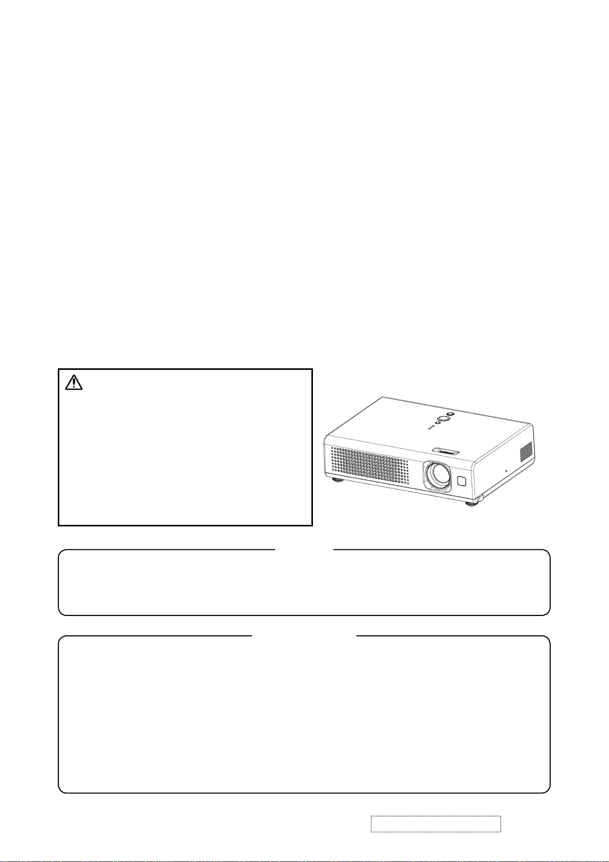
Features
• High Brightness
• Low Noise
• Compact Body
2. Specifications
Liquid clystal
panel
Lamp 165W UHB
RGB
signal
input
VIDEO
signal
input
AUDIO IN 200mVrms, 47kΩ or more (max. 3.0Vp-p)
Speaker output 1W(mono)
Power supply AC100~120V/2.7A,AC220~240V/1.5A
Power consumption 240W
Dimensions 285 (W) x 73 (H) x 202 (D) mm (Not including protruding parts)
Weight 2.2kg(4.85lbs)
Temperature range
Accessories
Drive system TFT active matrix
Panel size 1.5cm (0.6 type)
Number of pixels 1024 (H) x 768 (V)
Video : Analog 0.7Vp-p(75Ω termination)
RGB IN
VIDEO IN 1.0Vp-p(75Ω termination)
S-VIDEO IN
H/V. sync.: TTL level (positive/negative)
Composite sync.: TTL level
Y signal : 1.0±0.1Vp-p, (75Ω termination)
C signal : 0.286±0.1Vp-p(NTSC burst signal, 75Ω termination)
0.3±0.1Vp-p(PAL/SECAM burst signal, 75Ω termination)
Operation : 5~35°C
Storage : -20~60°C
Remote control x 1
RGB cable x 1
Power cords x 3
Batteries x 2
Filter cover for bottom up use x 1
User’s manuals x 1
ViewSonic Corporation Confidential
2
-
Do Not Copy PJ452
Page 6
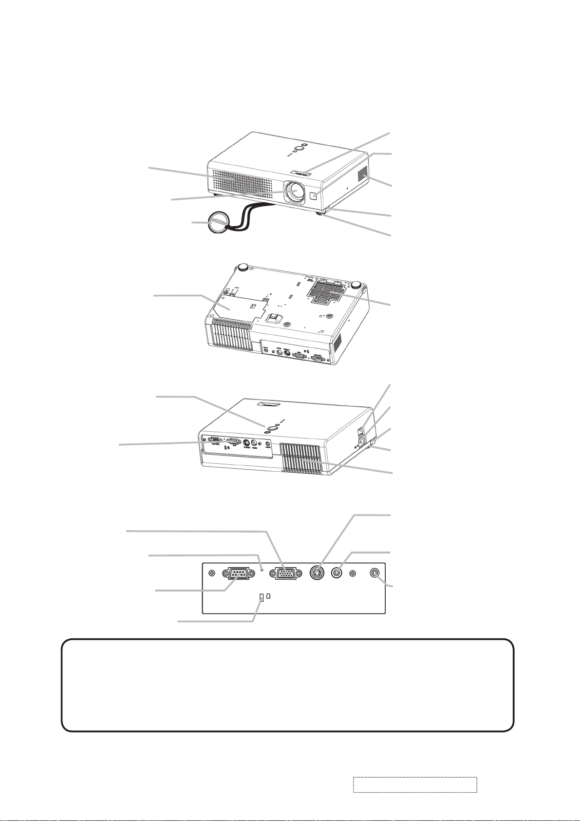
3. Names of each part
S-VIDEO
VIDEO
AUDIO
RGB
CONTROL
K
Part names
●
Projector
Vent
Lens
Lens cover
Lamp cover
(Lamp unit is inside.)
Control buttons
Front-Right side
Bottom side
Focus ring
Remote sensor
Speaker
Elevator button
Elevator foot
Filter cover
(Air filter and intake vent
are inside.)
Power switch
AC inlet
Elevator button
Ports
(See below.)
Elevator foot
Vent
Rear-Left side
S-VIDEO port
RGB port
Restart switch
CONTROL port
Kensington lock slot
Ports
VIDEO port
AUDIO port
NOTE (*) About Restart switch: This Projector is controlled by an internal
microprocessor. Under certain exceptional circumstances, the projector may not
operate correctly and the microprocessor will need to be reset. In such a case,
please push the Restart switch by using a cocktail stick or similar and before
turning on again, make the projector cool down at least 10 minutes without
operating. Only push the Restart switch in these exceptional instances.
ViewSonic Corporation Confidential
3
-
Do Not Copy PJ452
Page 7
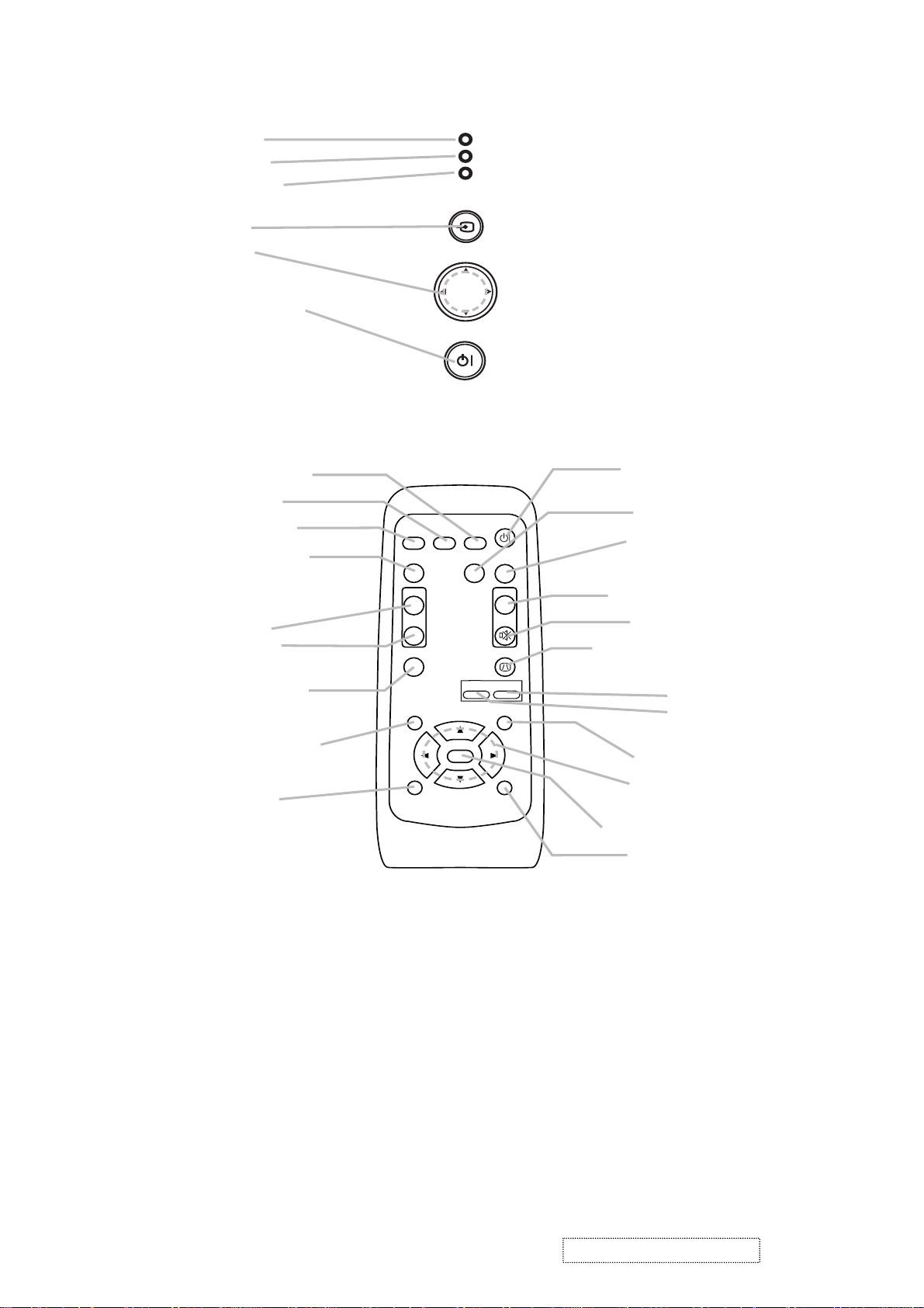
Controls
l
O
Zoom
enu cursor buttons
LAMP indicator
TEMP indicator
POWER indicator
INPUT button
Cursor buttons
▲,▼,◄,►
STANDBY/ON button
emote contro
SEARCH button
RGB button
VIDEO button
ASPECT button
VIDEO
ASPECT
LAMP
TEMP
POWER
INPUT
MENU
STANDBY/ON
SEARCH
RGB
AUTO
STANDBY/ON
BLANK
TANDBY/ON button
AUTO button
BLANK button
MAGNIFY
ON button
OFF button
FREEZE button
POSITION button
ESC button
MAGNIFY
ON
OFF
FREEZE
POSITION
ESC
ENTER
-
VOLUME
KEYSTONE
ZOOM
MUTE
MENU
RESET
V
LUME button
MUTE button
KEYSTONE button
+
+ button
- button
MENU button
M
▲,▼,◄,►
ENTER button
RESET button
ViewSonic Corporation Confidential
-
Do Not Copy PJ452
4
Page 8
4. Adjustment
4-1 Before adjusting
4-1-1 Selection of adjustment
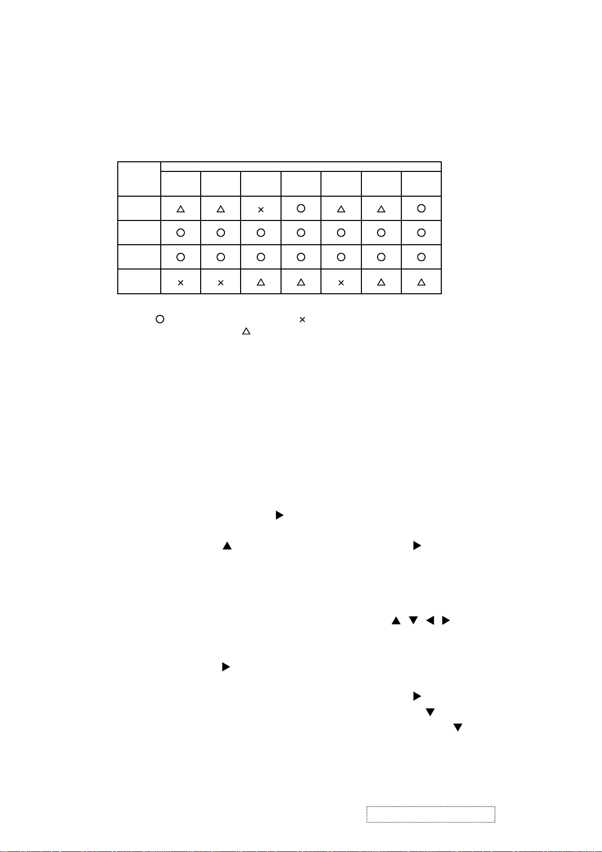
When any parts in the table 4-1 are changed, choose the proper adjusting items with the chart.
Table 4-1: Relation between the replaced part and adjustment
Replaced
part
Dichroic
optics unit
LCD/LENS
prism
assembly
PWB
assembly
Main
Lamp
unit
assembly
Convergence
(Chap.4-2)
E-POS
(Chap.4-3)
(Chap.4-4)
: means need for adjustment. : means not need for djustment.
Adjustment
Ghost
: means recommended.
Flicker
(Chap.4-5)
NRSH
(Chap.4-6)
White
balance
(Chap.4-7)
Color
uniformity
(Chap.4-8)
4-1-2 Setting of condition before adjustment
1. Before starting adjustment, warm up projector
for about 10 minutes.
2. Set Zoom Wide to Max. And project an image
with more than 1m (40 inches) in diagonal size.
3. Normalizing the video adjustment
Press the [MENU] button to display the Easy
menu. If Advance menu comes up, move to the
Easy menu.
Select RESET in the Easy menu and press [
or [ENTER] button to open the RESET menu
window. Choose EXECUTE with [
] button.
Note that no signal input may not allow to reset
the adjustments.
4. Select PICTURE > GAMMA in the Advance
menu to set to DEFAULT1.
Note that PICTURE menu is not selectable with
no signal input displayed.
5. Select PICTURE > COLOR TEMP > CUSTOM
in the Advance menu, then press [
] or [ENTER]
button to display the equalizing window. Set all
the values of OFFSET and GAIN in the window
to zero.
Caution: Before this performance, make a note
of your customer’s adjustments, because the
data is overwritten.
6. Perform all adjustments from the FACTORY
MENU.
Perform the following operations to display the
FACTORY MENU.
< When you use the remote control… >
a. Press the [MENU] button of remote control to
display the Easy menu. (If the Advance menu
appears, move to the Easy menu from EASY
]
MENU.)
b. Select the [RESET] in the Easy menu, and
then press the [
] or [ENTER] button.
c. Next, press the [RESET] button one time.
And hold the [RESET] button for 3 seconds
or more (the FACTORY MENU will appear).
< When you use the keypad… >
a. Press the [ ]/[ ]/[ ]/[ ] button of the projec-
tor to display the Easy menu. (If the Advance
menu appears, move to the Easy menu from
EASY MENU.)
b. Select the [
RESET
] in the Easy menu, and
then press the [ ] button.
c. Next, press the [
] button one time. And
repress and hold the [ ] button together
with the [INPUT] button for 3 seconds or
more (the FACTORY MENU will appear).
ViewSonic Corporation Confidential
5
-
Do Not Copy PJ452
Page 9

4-2 Convergence adjustment
Signal pattern for internal adjustment
Adjustment procedure
4-3
E-POS adjustment
(vertical bars adjustment)
Signal pattern for internal adjustment
112/255
4-4 Ghost adjustment
Signals for internal adjustment
30%
30%
0/255
112/255
1. Open FACTORY MENU and then select
OPTION > CNV-V. Use R and/or B so that
three colors of images can be converged at
center, top and bottom of the screen.
2. In the same way, select OPTION > CNV-H and
use R and/or B so that three colors of images
can be converged at center, left and right of the
screen.
Adjustment procedure
1. Make this adjustment after completing the
adjustment 4-2 Convergence adjustment.
2. Choose Advance menu > OPTION > SERVICE
> GHOST > R,G and B, and set them to zero.
3.
Open FACTORY MENU. Select DAC-P > E-POS
> R and use it so that vertical bars can disappear.
4. In the same way, select DAC-P > E-POS > G
and use it so that vertical bars can disappear.
5. In the same way, select DAC-P > E-POS > B
and use it so that vertical bars disappear.
Adjustment procedure
1. Make this adjustment after completing the
adjustment in 4-3.
2. Choose Advance menu > OPTION > SERVICE
> GHOST > R,G and B, and set them to zero.
3.
Use DAC-P - GHOST - R: in the FACTORY MENU
to adjust so that R color ghost is at a minimum.
(Set the adjustment value to default, and then
raise the value. When a ghost appears to the left
of a vertical line, reduce the value by 4 steps.)
4. In the same way, use DAC-P - GHOST-G: in
the FACTORY MENU to adjust so that G color
ghost is at a minimum.
5. In the same way, use DAC-P - GHOST-B: in
the FACTORY MENU to adjust so that B color
ghost is at a minimum.
ViewSonic Corporation Confidential
6
-
Do Not Copy PJ452
Page 10
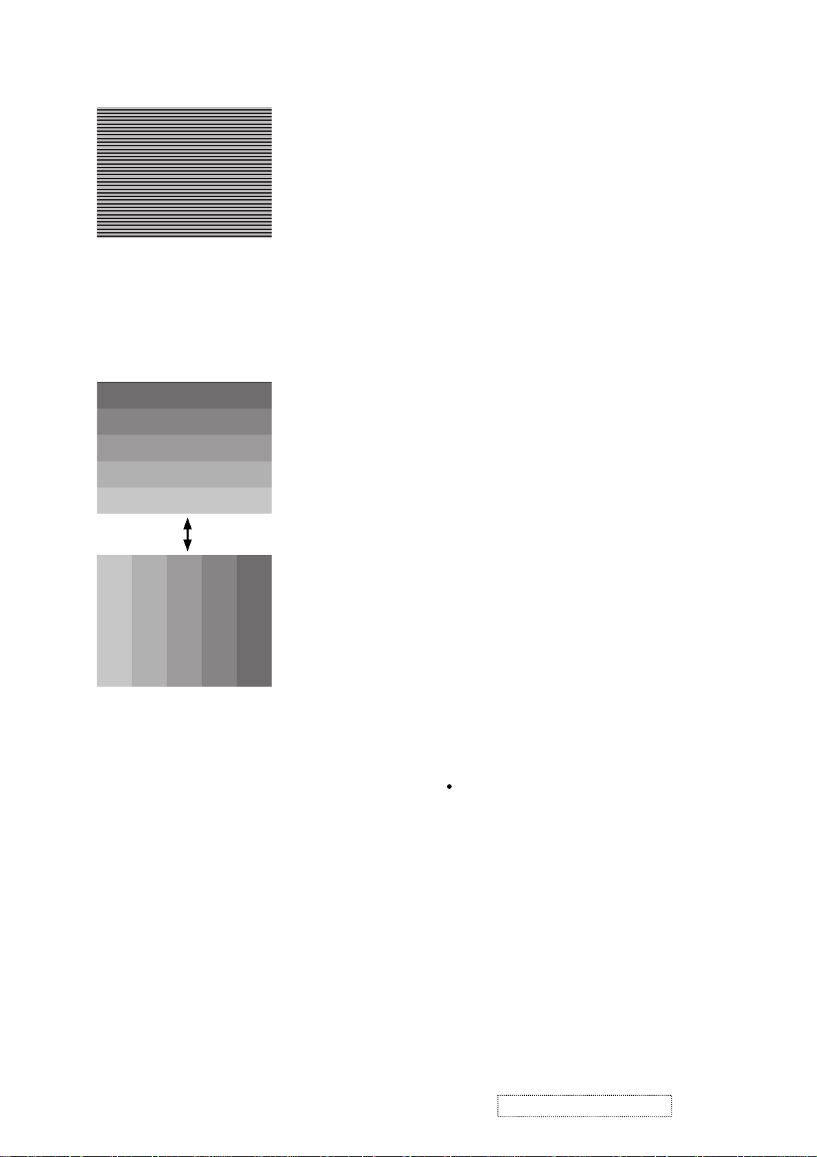
4-5 Flicker adjustment
(V.COM adjustment)
Signals for internal adjustment
4-6
NRSH adjustment (vertical stripe adjustment)
Signals for internal adjustment
64
/255
88
/255
112
/255
136
/255
160
/255
Press ENTER key
160
136
/255
112
/255
/25588/25564/255
Adjustment procedure
1. Make this adjustment after completing the
adjustment in 4-4 Ghost adjustment.
2.
Use DAC-P - V.COM - R: in the FACTORY
MENU to adjust so that the flicker at the center of
the screen is less than the flicker at the periphery.
(When the flicker is about the same across the
whole screen, adjust so that the flicker at the center
of the screen is somewhat less than elsewhere.)
3. In the same way, use DAC-P - V.COM-G: in the
FACTORY MENU to adjust the G color flicker.
4. In the same way, use DAC-P - V.COM-B: in the
FACTORY MENU to adjust the B color flicker.
Adjustment procedure
1. Make this adjustment after completing the
adjustment in 4-5 Flicker adjustment.
2. Use DAC-P - NRSH - R: in the FACTORY
MENU to adjust so that the vertical lines spaced
every 6 dots are as inconspicuous as possible.
(Reduce the adjustment value when black
stripes appear in the 2nd or 3rd tone from the
black side. Note that when the adjustment value
is lowered, white stripes may appear in the 2nd
or 3rd tone from the bright side. Should this
happen, adjust so that the stripes are as inconspicuous as possible.)
3.
In the same way, use DAC-P - NRSH - G: in the
FACTORY MENU to adjust vertical stripes of G color.
4.
In the same way, use DAC-P - NRSH - B: in the
Adjustment menu to adjust vertical stripes of B color.
4-7
White balance adjustment
(visual inspection)
Preparations
1. Perform these adjustments after the NRSH
adjustment described in Section 4-6.
2. Reset gamma correction before adjustment.
Place the cursor on [GAMMA] in the FACTORY
MENU, press the [RESET] key and select [DEFAULT].
Adjustment procedure
1. First, adjust the G color.
Select GAMMA, SUB-CNT, and G: in the FACTORY
2.
MENU. If the background is white solid, press the
[ENTER] key on the Remote control transmitter to
change to [G] monochrome in the 33-tone grayscale.
3. Adjust GAMMA, SUB-CNT, and G: in the FACTORY MENU so that brightness of 33 steps is
best.
4. Don’t adjust GAMMA, SUB-BRT, and G: in the
FACTORY MENU. Because we want to keep
the best contrast ratio.
5. Then adjust colors R and B.
6.
Select GAMMA, SUB-CNT, and G: in the FACTORY
MENU. If the background is white solid, press the
[ENTER] key on the Remote control trasmitter to
change to [W] monochrome in the 33-tone grayscale.
7. Adjust GAMMA, SUB-BRT, R: and B: in the
FACTORY MENU so that low-brigtness white
balance is best.
8. Adjust GAMMA, SUB-CNT, R: and B: in the
FACTORY MENU so that middle-brightness
white balance is best.
9. Repeat steps 7 to 8 above, and adjust so that
brightness white balance of 33 steps is best.
ViewSonic Corporation Confidential
7
-
Do Not Copy PJ452
Page 11
4-8 Color uniformity adjustment
Preparations
1.
Perform these adjustments after the white balance
adjustment described in Section 4-7.
2. Make a color uniformity adjustment for the follow-
ing four tones.
MIN tone (approx. 4% input signal)
MID-L tone (approx. 14% input signal)
MID-H tone (approx. 25% input signal)
MAX tone (approx. 57% input signal)
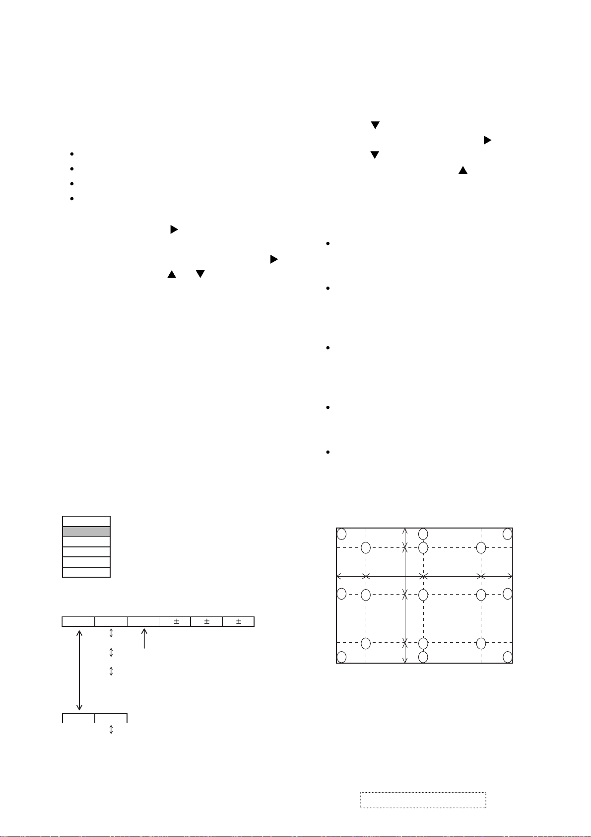
3. Place the cursor on [C.UNIF.] in the FACTORY
MENU and press the [ ] key. This displays the
Adjust Tone menu at the bottom of the screen.
To choose the tone to be adjusted, press the [ ]
key and then use the [ ] or [ ] key.
Select the major adjustment lattice point No.
and color, and then adjust them.
4. The major adjustment lattice point numbers (a
total of 17 points) corresponds to the major
adjustment lattice point positions in the diagram
on the right. The color uniformity of the entire
screen can be adjusted by adjusting the white
balance for each of the points starting in order
from the low numbers.
5. Adjustment point No.1 should not be adjusted,
because it controls the brightness of the entire
screen.
To temporarily turn correction off, place the
6.
cursor on [C.UNIF.] in the Adjust Tone menu and
press the [
] key. The ON/OFF menu appears.
Place the cursor on [ON] with the [ ] key and
press the [ ] key. To turn it on again, place the
cursor on [OFF] and press the [ ] key.
7. Although this adjustment can also be made
using internal signals, we will here use the
[ENTER] key on the Remote control transmitter
to select the following two signals.
Solid monochrome adjustment color (use G
color adjustment when a color differential
meter is used).
Solid white (use for adjustment other than
above).
8. Reset color-shading correction before adjust-
ment.
When 4 tones and all colors are to be reset,
place the cursor on [C.UNIF.] in the FACTORY
MENU, press the [RESET] key and select
[DEFAULT].
When only 1 tone is to be reset, place the
cursor on the tone to be reset, press the
[RESET] key and select [DEFAULT].
Single tone and monochrome resets cannot
be performed.
FACTORY MENU
VID-AD
C. UNIF.
DAC-P
GAMMA
STRIPE
OPTION
Adjust tone menu
C.UNIF
ON/OFF ON
MIN
MID-L
MID-H
MAX
OFF
No. 1 R 0
Major adjustment lattice point No.
G 0 B 0
Major adjustment lattice point position
14 12
6 4 8
H/6 H/3 H/3 H/6
10 11
2 1 3
7 5 9
15 17
ViewSonic Corporation Confidential
8
V/6
V/3
V/3
V/6
16
13
-
Do Not Copy PJ452
Page 12

Adjustment procedure 1
(When a color differential meter is used)
1. First adjust [MID-L] tone [G:].
2. Select adjustment point [No.2][G:].
When the background is not [G] monochrome,
press the [ENTER] key on the Remote control
transmitter to change to solid [G] monochrome.
3. Measure the illumination at adjustment points
No. 2, No.3, No.10 and No.11.
The values should be:
No.2 = Y2 [lx] No.10 = Y10 [lx]
No.3 = Y3 [lx] No.11 = Y11 [lx]
4. No.2 and No.3 adjustment point have the aver-
age of Y2 and Y3.
Y2 = ( Y2 + Y3 ) / 2 ± 2 [%]
Y3 = ( Y2 + Y3 ) / 2 ± 2 [%]
5. No.10 and No.11 adjustment point have the
average of Y10 and Y11.
Y10 = ( Y10 + Y11 ) / 2 ± 2 [%]
Y11 = ( Y10 + Y11 ) / 2 ± 2 [%]
6. Then adjust [MID-L] tone [R] and [B].
When the background is [G] monochrome,
press the [ENTER] key on the Remote control
transmitter to change to solid white.
7. Measure the color coordinates of adjustment
point [No.1] and make a note of them.
Assume that they are x = x1, y = y1.
Note: When the CL-100 color and color differ-
ence meter is used, the [ ∆ ](delta) mode
is convenient. When adjustment point
[No.1] color coordinate has been
selected, set the slide switch on the side
to [∆](delta) while holding down the [F]
button on the front panel. The measure-
ment shown after this displays the devia-
tion from measurement point 1.
8. Measure the color coordinates of measurement
point [No.2] and adjust [No.2][R:] and [B:] so
that the coordinates are as follows.
x = x1 ± 0.005 , y = y1 ± 0.010
9. Similarly, measure adjustment points [No.3] to
[No.17] and adjust their color coordinates start-
ing in order from the small number points.
This completes adjustments required for [MIN].
Note: Since excessive correction may lead to a
correction data overview during internal
calculations, use the following values for
reference.
[No.2] to [No.5] ± 40 or less
[No.6] to [No.9] ± 50 or less
[No.10] to [No.13] ± 70 or less
[No.14] to [No.17] ± 120 or less
10. Then adjust [MIN] tone [G] so that the adjust-
ment data set two times as much as [MID-L]
tone [G].
This completes [G] color adjustments.
11. Then adjust [MIN] tone [R] and [B].
Select [No.2] [B:] and press the [ENTER] key
on the Remote control transmitter to change to
solid white.
12. Measure the color coordinates of adjustment
point [No.1] and make a note of them.
Assume that they are x = x1, y = y1.
13. Now measure the color coordinates of mea-
surement point [No.2] and adjust [No.2][R:] and
[B:] so that the coordinates are as follows.
x = x1 ± 0.005 , y = y1 ± 0.010 (Target)
x = x1 ± 0.020 , y = y1 ± 0.040
14. Similarly, measure adjustment points [No.3] to
[No.17] and adjust their color coordinates start-
ing in order from the small number points.
This completes [MIN] tone adjustments.
15. Now make similar adjustments for [MID-H] tone.
(Adjust [MID-H] tone [G] so that the adjustment
data set half as many as [MID-L] tone [G].)
16. Now make similar adjustments for [MAX] tone.
(Adjust [MAX] tone [G] so that the adjustment
data set half as many as [MID-L] tone [G].)
ViewSonic Corporation Confidential
9
-
Do Not Copy PJ452
Page 13

Adjustment procedure 2
(visual inspection)
1. First adjust [MIN] tone [G:].
2. Select [No.2] [G:].
If the background is [G] monochrome, press the
[ENTER] key on the Remote control transmitter
to change to solid white.
3. View measurement point [No.2] and [No.3].
Lower the [G] color intensity only of the color
point whose [G] color is more intense than
measurement point [No.1].
4. View measurement point [No.10] and [No.11].
Lower the [G] color intensity only of the color
point whose [G] color is more intense than
measurement point [No.1], and raise the inten-
sity of the point whose color intensity is lower
than measurement point [No.1].
5. Now adjust the [MIN] tone for colors [R] and [B].
6. View measurement points [No.2], [No.3],
[No.10] and [No.11]. Adjust the [R] and [B] of
each measurement point so that they have the
same color as measurement point [No.1].
Adjustment technique:
First, adjust [B:] of the point whose color is to
be adjusted so that it approximates that of
[No.1]. If [R:] is low at this time, the image will
have cyan cast, in which case [R:] is increased.
On the other hand, if [R:] is excessive, the
image will have a magenta cast, in which case
[R:] is decreased.
Overall, a cyan cast makes it easy to see color
shading.
7. Next, view measurement points [No.4], [No.5],
[No.12], [No.13] and make similar adjustments.
Then adjust measurement points [No.6], [No.7],
8.
[No.8], [No.9], [No.14], [No.15], [No.16] and [No.17].
This completes the [MIN] tone adjustments.
9. Make similar another three tones as described
in steps 1 to 8 above.
No. 2 deviation range No. 10 deviation range No. 3 deviation range No. 11 deviation range
14
10
15
12
6
4
2
1
5
7
13
16
8
3
11
9
17
14
10
15
12
4
6
2
1
5
7
13
16
8
3
11
9
17
14
10
15
12
6
4
2
1
5
7
13
16
8
3
11
9
17
14
10
15
12
4
6
2
1
5
7
13
16
8
3
11
9
17
No. 4 deviation range No. 12 deviation range No. 5 deviation range No. 13 deviation range
14
10
15
12
6
4
2
1
5
7
13
16
8
3
11
9
17
14
10
15
12
6
4
2
1
5
7
13
16
8
3
11
9
17
14
10
15
12
6
4
2
1
5
7
13
16
8
3
11
9
17
14
10
15
12
4
6
2
1
5
7
13
16
8
3
11
9
17
No. 6 deviation range No. 7 deviation range No. 8 deviation range No. 9 deviation range
14
10
15
14
10
15
8
3 11
9
16
17
14
10
15
12
6
4
1
2
5
7
13
16
8
3
11
9
17
14
10
15
12
6
4
2
1
5
7
13
16
8
3
11
9
17
12
6
4
2
1
5
7
13
12
4
6
2
1
5
7
13
16
8
3
11
95
17
No. 14 deviation range No. 15 deviation range No. 16 deviation range No. 17 deviation range
14
12
4
6
16
8
14
12
6
4
16
8
14
12
6
4
16
8
14
12
4
6
16
8
3
10
15
3
2
1
5
7
13
11
9
17
10
15
1
2
5
7
13
11
9
17
10
15
2
7
13
3
1
5
11
9
17
ViewSonic Corporation Confidential
2
10
7
15
-
Do Not Copy PJ452
10
13
1
3
11
5
9
5
17
Page 14

5. Troubleshooting
Check points
*Top view of the projector after the silver gilding on the lamp house detached.
PWB Assembly SW
E801
E804
E301
E802
E800
D303
(LAMP)
P501
P701
ESPL
E803
D302
(TEMP)
D301
(Power)
P601
PWB assembly MAIN
E807
E805
E302
E806
PWB assembly REMOTE
ViewSonic Corporation Confidential
11
-
Do Not Copy PJ452
Page 15
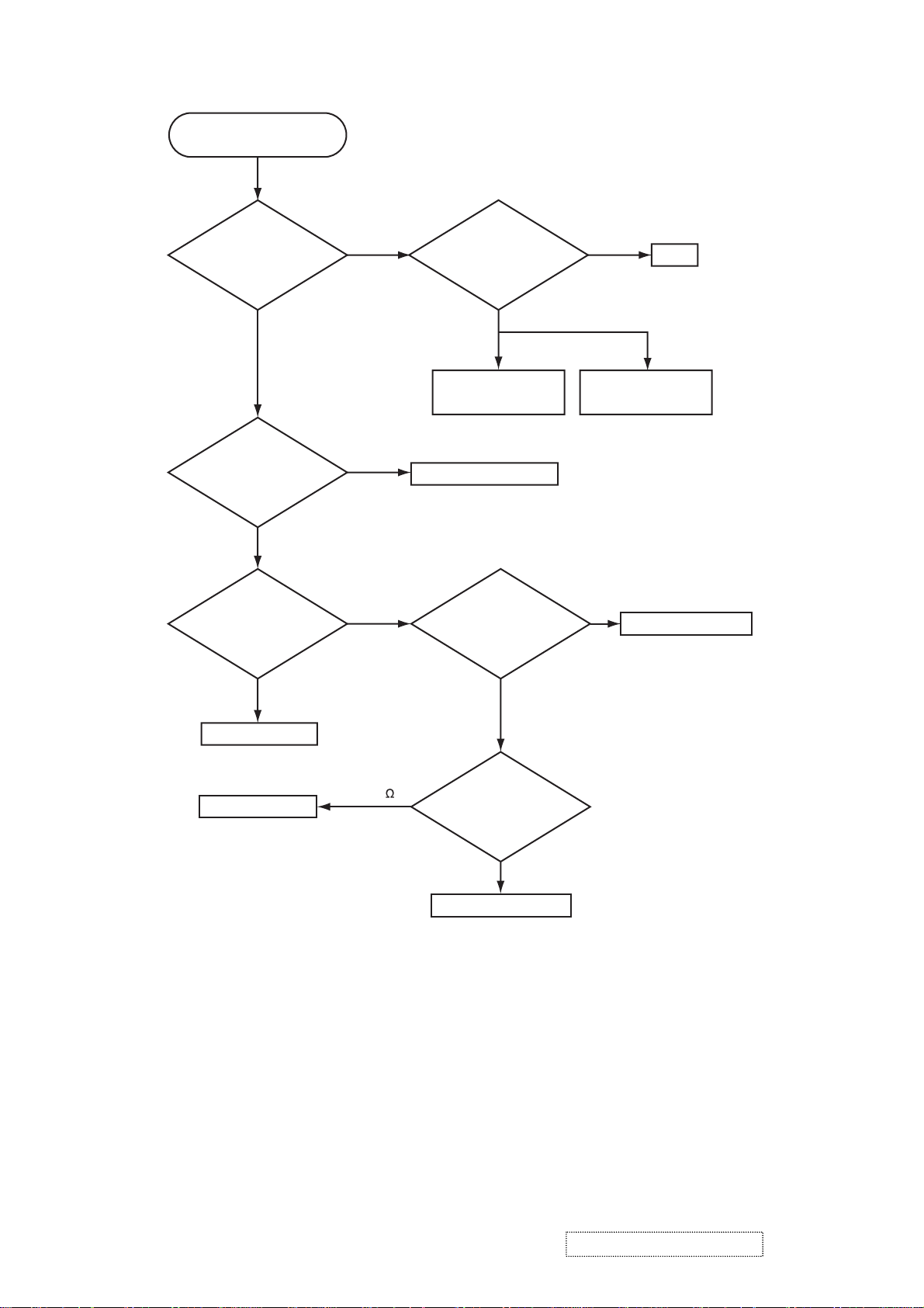
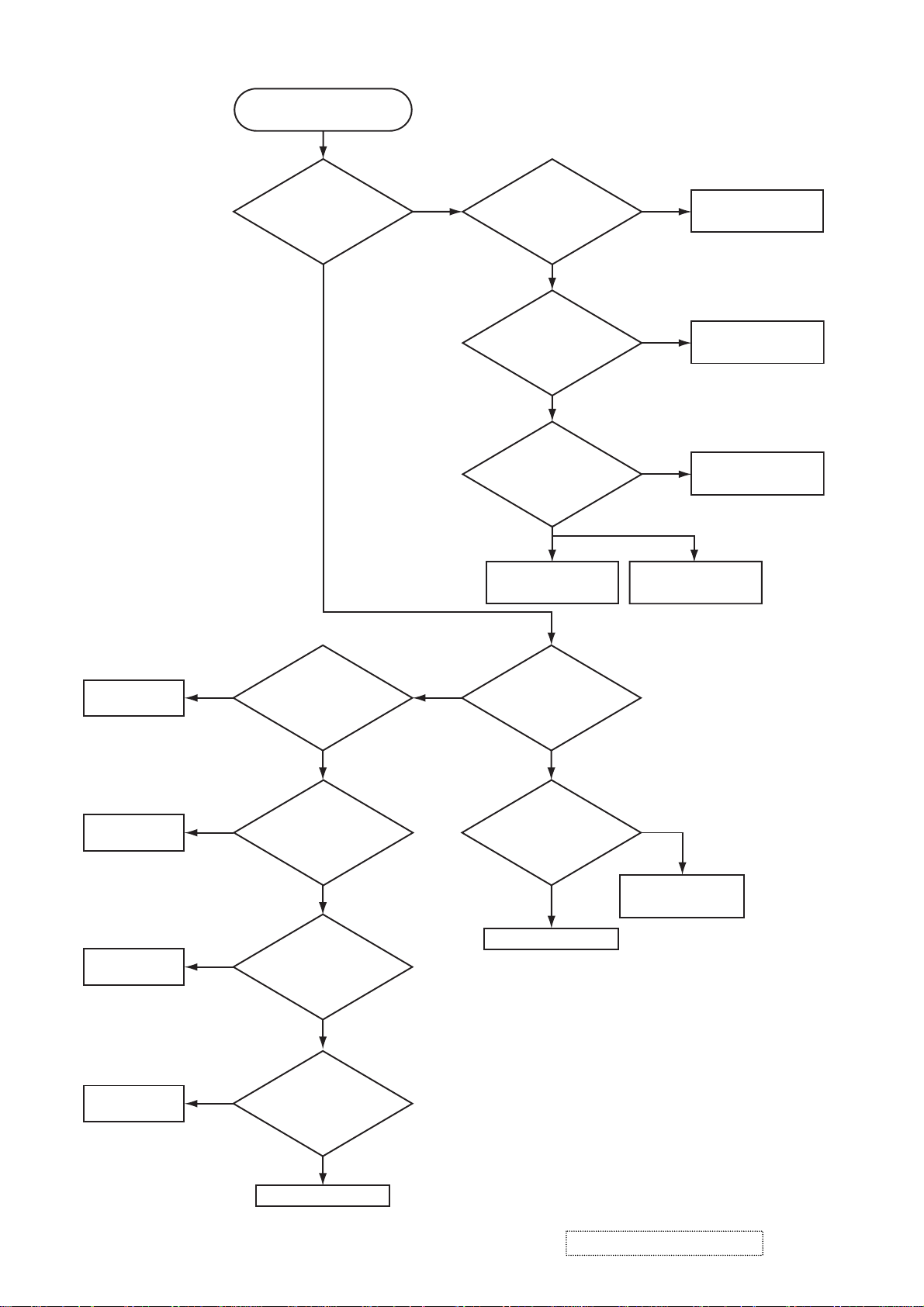
Power can not be turned on
Are
voltage input at
pins (1)(3)(5)(7) of E800
on the PWB assembly
Main at standby
mode?
YES
What is the state of
TEMP indicator D302?
Not light
What is the state of
LAMP indicator D303?
NO
(1): +0V
(3): +17V
(5): +6.6V
(7): +4.1V
Blinks
Blinks
Disconnect
TSW form Power unit
(circuit). And check
TSW short or
open?
Short
Power unit (circuit)
Jump to * on the page 13
Is the LAMP DOOR
set?
Open
Fuse on the
Power unit (circuit)
NG
TSW
Set the LAMP DOOR
Not light
PWB assembly Main
PWB assembly Main
Short (0 )
OK
Unplug
power cord and
disconnect cable CNLC,
then measure resistance
between pins (1)
and (2) of
CNLC.
Open
PWB assembly Limit SW
ViewSonic Corporation Confidential
-
Do Not Copy PJ452
12
Page 16
Lamp does not light
What is the
state of LAMP indicator
D303 during operation?
Not light
Light NG
Is the LAMP
installation correct?
YES
Change the lamp.
Does lamp light?
Not light
Is the
voltage at the
(1) of E804 on the PWB
assembly MAIN fixed to "L"
during warming-up?
NO
Power unit (ballast)
Light
YES
"L" = 0V
Power unit (circuit)
Install the Lamp
Lamp
PWB assembly MAIN
DC FAN
(Sub)
DC FAN
(Exhaust)
DC FAN
(B Panel)
DC FAN
(R/G Panel)
NO
H (3.3V)
H (3.3V)
H (3.3V)
Is the
voltage at the pin
(1) of E806 on the PWB
assembly MAIN set
to “L” ?
YES
(L=0V)
Measure
voltage at pin(1)
of E801 on PWB
assembly MAIN.
L (0V)
Measure
voltage at pin(1)
of E807 on PWB
assembly MAIN.
L (0V)
Measure
voltage at pin(1)
of E802 on PWB
assembly MAIN.
*
Blinks
What is the state
of TEMP indicator D302?
Not light
Is the voltage
at the (3) of E804 on
the PWB assembly MAIN
set to "L" during
warming-up?
YES
Power unit (ballast)
NO
"L" = 0V
PWB assembly MAIN
L (0V)
PWB assembly MAIN
ViewSonic Corporation Confidential
-
Do Not Copy PJ452
13
Page 17
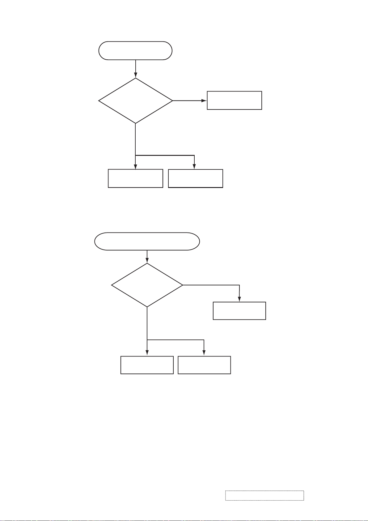
Picture is not displayed only
when the RGB signal is input
Check at operating mode
Are
voltage input
at pins(1)(3)(5)(7) of
E800 on the PWB
assembly
MAIN?
YES
NO
(1):+13.2V
(3):+17V
(5):+6.6V
(7):+4.1V
Power unit
(circuit)
PWB assembly M
Picture is not displayed only when the
VIDEO, S-VIDEO signal is input
voltage input at
pins(1)(3)(5)(7) of E800
on the PWB assembly
AIN
Check at operating mode
Are
MAIN?
YES
(1): +13.2V
(3): +17V
(5): +6.6V
(7): +4.1V
LCD PRISM
assembly
NO
Power unit (circuit)
PWB assembly MAIN
ViewSonic Corporation Confidential
LCD PRISM
assembly
-
Do Not Copy PJ452
14
Page 18
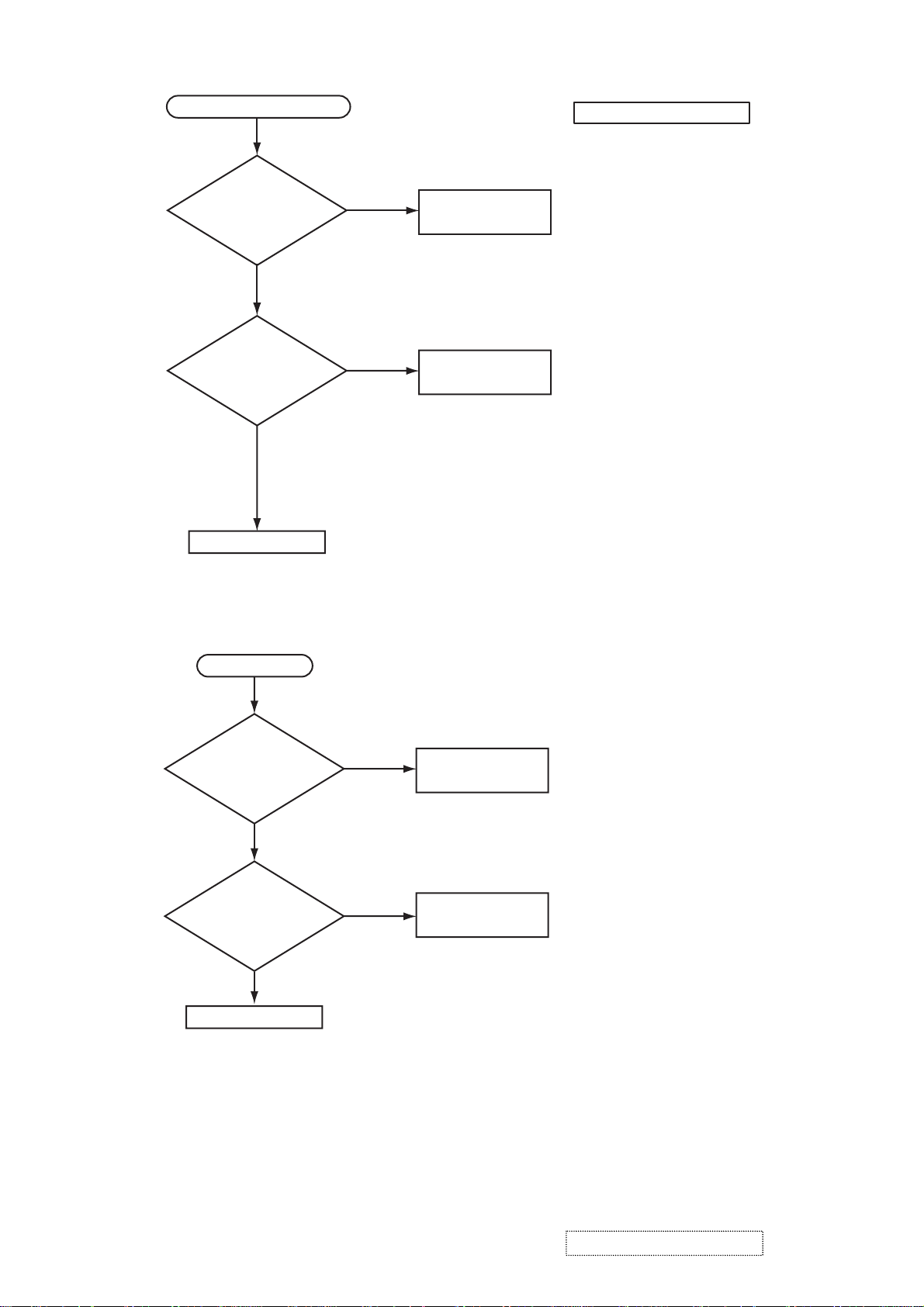
Can not control to RS-232C
Check the
RS-232C cable.
Are pin No. 2 and 3
crossed?
YES
NO
Use cross cable
The check after parts change
1. PC power supply OFF
2. Connection of cable
3. Projector starting
4. PC starting
*When not operating :
PC set up change of cable.
Check the
power supply voltage
of E800 the voltage
correct?
(1): +13.2V
YES
(3): +17V
(5): +6.6V
(7): +4.1V
PWB assembly MAIN
No sound
Are
voltage input at pin
(1)(3)(5)(7) of the E800 on
the PWB assembly
MAIN?
YES
Turn off
the projector and
disconnect the Speaker
cable from ESPL.Measure
the resistance of
the Speaker
(1): +13.2V
(3): +17V
(5): +6.6V
(7): +4.1V
.
NO
NO
about 8Ω
Power unit (circuit)
Power unit (CIRCUIT)
PWB assembly MAIN
0Ω or infinity
Speaker
ViewSonic Corporation Confidential
-
Do Not Copy PJ452
15
Page 19

6. Service points
6-1 Lead free solder [CAUTION]
This product uses lead free solder (unleaded) to help preserve the environment. Please read these
instructions before attempting any soldering work.
CAUTION
Always wear safety glasses to prevent fumes or molten solder from getting into the eyes. Lead free solder
can splatter at high temperatures (600˚C).
Lead free solder indicator
Printed circuit boards using lead free solder are engraved with an "F" or "LF".
Properties of lead free solder
The melting point of lead free solder is 40-50˚C higher than leaded solder.
Servicing solder
Solder with an alloy composition of Sn-3.0Ag-0.5Cu or Sn-0.7Cu is recommended.
Although servicing with leaded solder is possible, there are a few precautions that have to be taken. (Not
taking these precautions may cause the solder to not harden properly, and lead to consequent malfunctions.)
Precautions when using leaded solder
Remove all lead free solder from soldered joints when replacing components.
If leaded solder should be added to existing lead free joints, mix in the leaded solder thoroughly after the
lead free solder has been completely melted (do not apply the soldering iron without solder).
Servicing soldering iron
A soldering iron with a temperature setting capability (temperature control function) is recommended.
The melting point of lead free solder is higher than leaded solder. Use a soldering iron that maintains a high
stable temperature (large heat capacity), and that allows temperature adjustment according to the part being
serviced, to avoid poor servicing performance.
Recommended soldering iron:
Soldering iron with temperature control function (temperature range: 320-450˚C)
Recommended temperature range per part:
Part Soldering iron temperature
Mounting (chips) on mounted PCB 320˚C±30˚C
Mounting (chips) on empty PCB 380˚C±30˚C
Chassis, metallic shield, etc. 420˚C±30˚C
The PWB assembly which has used lead free solder
(1) PWB assembly MAIN
(2) PWB assembly REMC
(4) POWER UNIT (BALLAST)
(5) POWER UNIT (CIRCUIT)
(3) PWB assembly SW
ViewSonic Corporation Confidential
16
-
Do Not Copy PJ452
Page 20
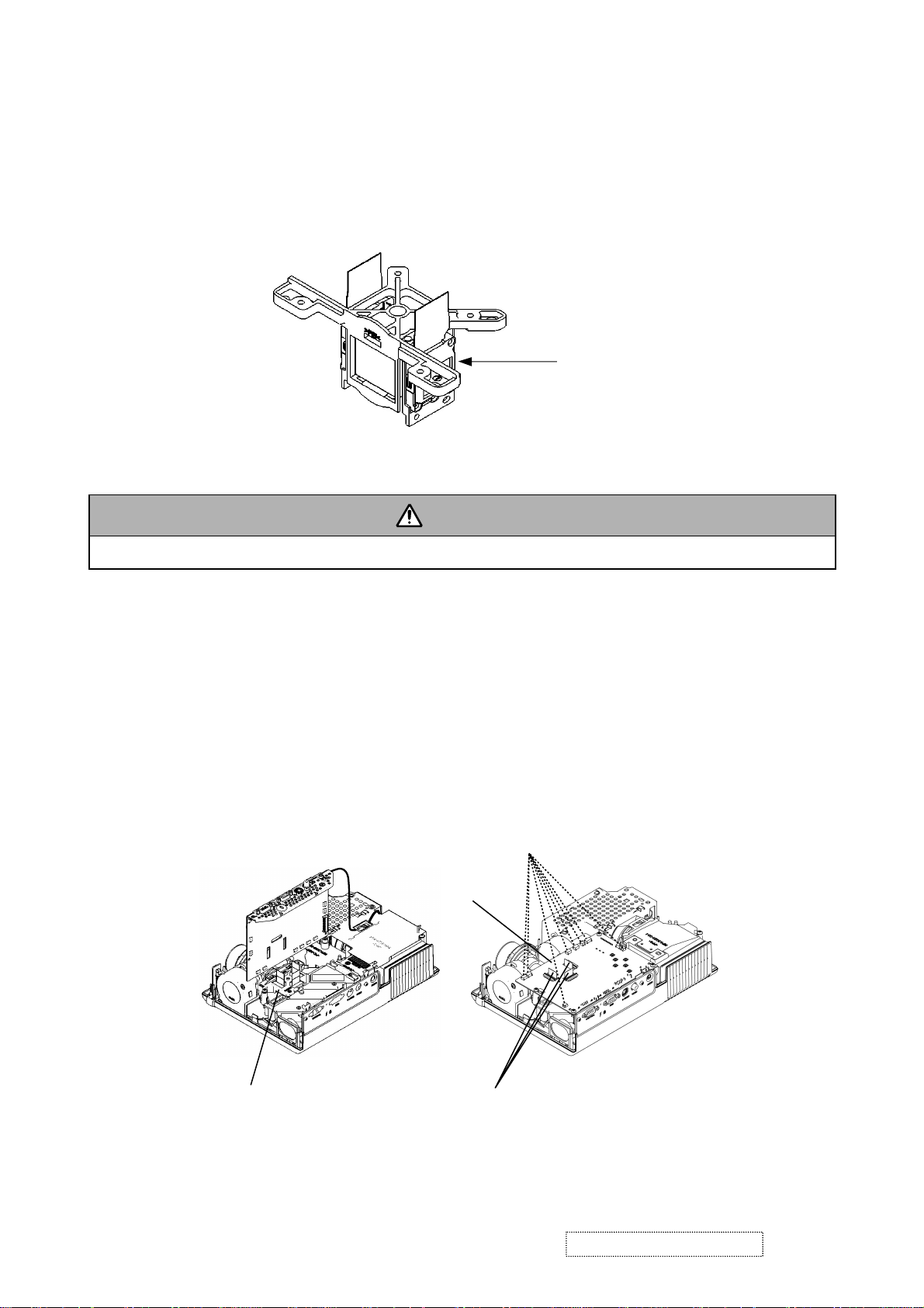
6-2 Replacing The LCD/PRISM assembly
You should not replace separately the parts of the LCD/PRISM assembly. In case of a failure in any parts of
LCD/PRISM assembly, replace the whole LCD/PRISM assembly.
Do not disassemble the unit
becaouse replacement of separate
parts is not possible.
LCD/PRISM ASSY
6-3 Cleaning up dust from panels and optical filters
1. Preparation
WARNING
Wear sunglasses to protect your eyes when you maintain the projector with its lamp on.
Please prepare cleaning tools and materials as follows. And prepare relatively clean room not to work in
additional dust, while removing operation.
(1) Swab for cleaning "Cotton stick L147"
(2) Air duster (Dust blower, spray can)
(3) Vacuum cleaner
2. Disassemble and open the maintenance hole.
(1) Turn off the projector, and unplug the power cord.
(2) Remove the top cover, according to the notice 1 of chapter 8.
(3) Remove the PWB assembly MAIN, according to the notice-2 of the chapter 8.
(4) Remove the Panel Cover.
Connect cables
PWB assembly MAIN
Remove Panel Cover
Flexible cables of LCD panels
(5) Attach the PWB assembly MAIN in original place, and connect cables indicated above. Note that flexi-
ble cables of LCD panels should come to the upper portion of PWB assembly MAIN, but don’t connect them to the connectors. Make sure that flexible cables’ terminals don’t touch to any other parts
during maintenance, especially when the projector is turned on.
ViewSonic Corporation Confidential
17
-
Do Not Copy PJ452
Page 21

3. Maintenance point
Swab
Holder
Optical filter
Each color part has same
construction.
By using swab and air duster,
you can easily remove dust
from panel and optical filter.
Panel
Actual formation
Separatied formation
4. Cleaning the panels and optical filters
(1) Turn on the set and lit on the lamp.
(2) By using swab and air duster, remove the dust. Focusing dust makes you check the dust on screen.
Swab
Panel
• While removing the dust, separated dust
will be blown off by air cooling system.
• Please pay attention not to damage panel
and optical filter.
Holder
Air
Optical filter
5. Re-assembly
(1) Turn off the set and remove the PWB assembly MAIN.
(2) Set the
Panel cover
.
(3) Re-assemble the PWB assembly MAIN.
(4) Re-assemble the set.
(5)
While re-assembling, please clean the Panel cover and intake filter and filter cover by using vacuum cleaner.
ViewSonic Corporation Confidential
18
-
Do Not Copy PJ452
Page 22

6-4 Cleaning up dust from multilens
1. Preparation
Please prepare cleaning tools and materials as follows.
(1) Air duster (Dust blower, spray can)
(2) Swab for cleaning ”Cotton stick L147”
(3) Vacuum cleaner
2. Remove the lamp door and the lamp assy.
(1) Turn off the projector, and unplug the power cord.
(2) Remove the lamp door and the lamp assembly according to the description of chapter “Replacing the
LAMP”.
3. Maintenance point
4. Cleaning the multilens
(1) By using the air duster, remove the dust on multilens.
(2) Remove the dust on the ML-A surface using the air duster, then wipe the surface.
CAUTION :
Use special caution not
to damage the ML-A.
CAUTION :
Use special caution not
to damage the ML-A.
5. Set the lamp door and the lamp assembly.
Set the lamp door and the lamp assembly accoding the description of “Replacing the LAMP”.
ViewSonic Corporation Confidential
19
-
Do Not Copy PJ452
Page 23

6-5 Putting batteries
WARNING
Always handle the batteries with care and use them only as directed. Improper use may result in battery
explosion, cracking or leakage, which could result in fi re, injury and/or pollution of the surrounding environment.
• Be sure to use only the batteries specifi ed. Do not use batteries of different types at the same time. Do
not mix a new battery with used one.
• Make sure the plus and minus terminals are correctly aligned when loading a battery.
• Keep a battery away from children and pets.
• Do not recharge, short circuit, solder or disassemble a battery.
• Do not allow a battery in a fi re or water. Keep batteries in a dark, cool and dry place.
• Do not give the battery a physical impact.
• If you observe a leakage of a battery, wipe out the flower and then replace a battery. If the flower
adheres your body or clothes, rinse well with water immediately.
• Obey the local laws on disposing a battery.
To use the remote control, please load the batteries. Whenever the remote control starts to malfunction,
replace the batteries. If you won’t use the remote control for an extended period, remove the batteries from
the remote control and store them in a safe place.
1. Remove the battery cover.
Slide back and remove the battery cover in the direction of the arrow.
2. Take old batteries out and/or put new batteries in.
When putting in batteries, align and insert the two AA batteries according to their plus and minus terminals
as indicated in the remote control.
3. Close the battery cover.
Replace the battery cover in the direction of the arrow and snap it back into place.
ViewSonic Corporation Confidential
20
-
Do Not Copy PJ452
Page 24

6-6 Air filter
WARNING
●
Do not replace the air fi lter during use or immediately after use. Handling while the projector is in a high
temperature could cause a burn and/or malfunction to the projector. Before operating, make sure that the
power swich is off, that the power cord is not plugged in, and that the projector is cool adequately.
●
Use only the air fi lter of the specifi ed type. Do not use the projector with the air fi lter and fi lter cover
removed.
●
Avoid wetting the projector or inserting liquids in the projector. It could result in a fi re, an electric shock,
and/or malfunction to the projector.
CAUTION
●
Please replace the air fi lter when it is damaged or too soiled, and also when you replace the lamp.
When the indicators or a message prompts you to clean the air filter, clean the air filter as soon as possible.
If the air filter becomes clogged by dust or the like, internal temperatures rise and the power may be automatically turned off for malfunction prevention.
1. Disconnect all the connectors and adapters that were connected to the projector’s ports. Then slowly turn
the projector so that the lens-side is facing up. Please be careful for a projector not to fall. While the projector
is placed lens-side up, hold the projector.
2. Remove the filter cover and the air filter. Hold the knobs while pulling out it.
Usual filter cover
Filter cover’s
knobs
Filter cover for bottom-up use
Filter cover’s
knobs
Air filter’s
knob
3. Apply a vacuum cleaner to the vent of the projector for the air filter. And then slowly turn the projector
bottom up.
4. Apply a vacuum cleaner to the air filter and filter cover.Then set a new or cleaned air filter into place.In
case of the filter cover for bottom-up use, remove the air filter from the filter cover.
Claws
Air filter
Rail of air filter
Filter cover for bottom-up use
Please replace the air filter when it is damaged or too soiled.
The air filter type number = NJ20922
An air filter of specified type will come even with the replacement lamp for this projector.
ViewSonic Corporation Confidential
21
-
Do Not Copy PJ452
Page 25

5. Position the air filter and filter cover into place.
Usual filter cover
Push the points of “PUSH” word
with claws to fix the air filter.
Filter cover for bottom-up use
Interlocking the tabs, snap the filter cover into place.
Tabs
Interlocking the tabs,
snap the filter cover into place.
Ta bs
6. Slowly turn the projector so that the top is facing up, except for the case of bottom-up use.
7. Turn the projector on, and reset the filter time using the FILTER TIME function of OPTION menu.
(1) While projector running, press the MENU button of remote control or the [
]/[ ]/[]/[]
button of
keypad to open menu.
(2) Choose FILTER TIME in EASY menu or in OPTION of Advance menu.
(3)
Press and hold RESET button of the remote control or [ ] button of the keypad for 3 seconds. FILTER
TIME reset window will appear.
(4) Choose RESET using
[ ] button.
NOTE • Incorrectly resetting of the fi lter timer (resetting without replacement, or neglect of resetting after
replacement) will result in incorrect message functions.
ViewSonic Corporation Confidential
22
-
Do Not Copy PJ452
Page 26

6-7 Lamp
WARNING
●
The projector uses a high-pressure mercury glass lamp. The lamp can break with a loud bang, or burn
out, if jolted or scratched, handled while hot, or worn over time. Note that each lamp has a different lifetime, and some may burst or burn out soon after you start using them. In addition, when the bulb bursts, it
is possible for shards of glass to fly into the lamp housing, and for gas containing mercury to escape
from the projector’s vent holes.
●
About disposal of a lamp • This product contains a mercury lamp; do not put in trash. Dispose of in
accord with environmental laws.
For lamp recycling, go to www.lamprecycle.org. (in the US) For product disposal, contact your local government agency or www.eiae.org (in the US) or www.epsc.ca (in Canada).
• If the lamp should break (it will make a loud bang when it does), unplug the power cord from
the outlet. Note that shards of glass could damage the projector’s internals, or cause injury
during handling.
Disconnect
the plug
from the
power
outlet
• If the lamp should break (it will make a loud bang when it does), ventilate the room well, and
make sure not to breathe the gas that comes out of the projector vents, or get it in your eyes
or mouth.
• Before replacing the lamp, turn the projector off and unplug the power cord, then wait at least
45 minutes for the lamp to cool suffi ciently. Handling the lamp while hot can cause burns, as
well as damaging the lamp.
HIGH VOLTAGE HIGH TEMPERATURE HIGH PRESSURE
• Never unscrew except the appointed (marked by an arrow) screws.
• Do not open the lamp cover while the projector is suspended from above. This is dangerous,
since if the lamp’s bulb has broken, the shards will fall out when the cover is opened. In addition, working in high places is dangerous.
• Do not use the projector with the lamp cover removed. At the lamp replacing, make sure that
the screws are screwed in fi rmly. Loose screws could result in damage or injury.
• Use only the lamp of the specifi ed type.
• If the lamp breaks soon after the fi rst time it is used, it is possible that there are electrical
problems elsewhere besides the lamp.
• Handle with care: jolting or scratching could cause the lamp bulb to burst during use.
• If the indicators or a message prompts you to replace the lamp (see the section “Related
Messages” and “Regarding the indicator Lamps”), replace the lamp as soon as possible.
Using the lamp for long periods of time, or past the replacement date, could cause it to burst.
Do not use old (used) lamps; this is a cause of breakage.
ViewSonic Corporation Confidential
23
-
Do Not Copy PJ452
Page 27

Replacing the Lamp
When the indicators or a message prompts you to replace the lamp, replace the lamp as soon as possible.
1. Turn the projector off, and unplug the power cord. Allow the lamp to cool for at least 45 minutes.
2. Prepare a new lamp (the lamp type number = DT00702 or RCL-004). If the projector is mounted on the
ceiling, or if the lamp has broken, also ask the dealer to replace the lamp.
In the case of replacement by yourself,
3. After making sure that the projector has cooled adequately, slowly
turn over the projector, so that the bottom is facing up.
4. Please loosen the screw (marked by arrow). Then, unhook the
claws of the lamp cover and remove the lamp cover.
5. Loosen the 2 screws (marked by arrow) of the lamp, and slowly pick
up the lamp by the handles.
6. Insert the new lamp, and retighten firmly two screws
that are loosened in the previous process to lock it in
place.
7. Interlocking the 2 tabs of the lamp cover to the pro-
jector, position the lamp cover on the projector, and
push the center point of two claws to fix the lamp
cover. Then retighten firmly the screw of the lamp
cpver.
8. Slowly turn the projector so that the top is facing up.
9. Turn the projector on, and reset the lamp time using
the LAMP TIME function of OPTION menu.
(1) Select the item of LAMP TIME in OPTION of Advance menu
(2) Press and hold RESET button
of the keypad
for 3 seconds. LAMP TIME reset window will
of the remote control or [ ] button
appear.
(3) Choose RESET using [
]
button.
NOTE • When the lamp has been replaced after the message of “THE POWER WILL TURN OFF AFTER
0hr .” is displayed, complete the following operation within 10 minutes of switching power on.
Incorrectly resetting of the lamp timer (resetting without replacement, or neglect of resetting after
replacement) will result in incorrect message functions.
ViewSonic Corporation Confidential
24
-
Do Not Copy PJ452
Page 28

6-8 Other care
WARNING
Before caring, make sure the power switch is off and the power cable is not plugged in, and then allow the
projector to cool suffi ciently. The care in a high temperature state of the projector could cause a burn and/
or malfunction to the projector.
Avoid wetting the projector or inserting liquids in the projector. It could result in a fi re, an electric shock,
and/or malfunction to the projector.
• Don’t put a container containing water , cleaner or chemicals near the projector.
• Don’t use aerosols or sprays.
CAUTION
Please take right care of the projector according to the following. Incorrect care could cause not only an
injury but adverse influence such as discoloration, peeling paint, etc.
• Do not use cleaner or chemicals other than those listed below.
• Do not polish or wipe with hard objects.
Inside of the projector
In order to ensure the safe use of the projector, it needs to clean and inspect the projector about once every year.
Caring for the lens
If the lens is flawed, soiled or fogged, it could cause deterioration of display quality. Please take care of the
lens, being cautions of the handling.
1. Turn the projector off, and unplug the power cord. Allow the projector to cool sufficiently.
2. After making sure that the projector is cool adequately, lightly wipe the lens with a commercially available
lens-cleaning wipe. Do not touch the lens directly with your hand.
Caring for the cabinet and remote control
Incorrect care could have adverse influence such as discoloration, peeling paint, etc.
1. Turn the projector off, and unplug the power cord. Allow the projector to cool sufficiently.
2. After making sure that the projector is cool adequately, lightly wipe with gauze or a soft cloth.
If soiling is severe, dip soft cloth in water or a nautral cleaner dilute in water, and wipe lightly after wringing
well. Then, wipe lightly with a soft, dry cloth.
ViewSonic Corporation Confidential
25
-
Do Not Copy PJ452
Page 29

6-9 Notice of AUTO adjustment
Use of AUTO adjustment with the image through RGB input optimizes V_POSI, H_POSI, H_SIZE and
H_PHASE automatically.
In case that projected image has dark tone around its peripheral, AUTO operation sometimes makes artifacts
in the image, shifts capture area and so on. Those failures are caused by period of image data is not exactly
distinguished to period of blanking on signal processing.
To avoid such phenomena, AUTO function should be used with the full size picture that has bright tone on its
peripheral.
Image when AUTO operates correctly
Note
1) The phenomenon at the failure of AUTO adjustment depends on resolution of input source, scene of pic-
ture etc.
2) There is no failure above in AUTO with video source through VIDEO, S-VIDEO or COMPONENT input. The
reason is why recognition of input signal’s standard does not need to search the capture range from input
signal itself.
Image when AUTO fails.
Noting image of top or bottom lines.
Shift of the image to East or West.
Artifacts on image. Etc.
ViewSonic Corporation Confidential
26
-
Do Not Copy PJ452
Page 30

6-10 Related Messages
When the unit’s power is on, messages such as those shown below may be displayed. When any such message
is displayed on the screen, please respond as described below.
Although these messages will be automatically disappeared around several minutes, it will be reappeared every
time the power is turned on.
Message Description
To maximize
performance, lamp
replacement is
recommended.
CLEAN THE AIR FILTER
POWER OFF FIRST,
THEN CLEAN THE AIR FILTER.
AFTER CLEANNIG THE AIR
RESET THE FILTER TIMER.
NO INPUT IS DETECTED
SYNC IS OUT OF RANGE
ON ***
CHECK THE AIR FLOW
CLEAN THE AIR FILTER
THEN CLEAN THE AIR
AFTER CLEANING THE AIR
RESET THE FILTER TIMER.
FILTER,
ON ***
fH
*****kHz fV *****Hz
POWER OFF FIRST,
FILTER.
FILTER,
After the lamp running reaches 2000 hours, the warning message is displayed,
but it won't shut the unit off.
The message displays for 30 seconds when the PJ is turned on. If we push any
button while displaying the message, the message disappear.
The time the fi lter timer has counted has reached 100 hours.
Please clear or change the air fi lter by referring to the section "Air fi lter". After caring
for the air fi lter, Please be sure to reset the fi lter timer.
There is no input signal.
Please confi rm the signal input connection, and the status of the signal source.
The horizontal or vertical wavelength of the inputted signal is outside of the
response parameters of this unit.
Please confi rm the specs for this unit or the signal source specs.
The internal portion temperature is rising.
Please turn the power OFF, and allow the unit to cool down at least 20 minutes.
After having confi rmed the following items, please turn the power ON again.
• Is there blockage of the air passage aperture?
• Is the air fi lter dirty?
• Does the peripheral temperature exceed 35°C?
• If the same indication is after the treatment, please set the HIGH at FAN SPEED
of the item SERVICE of the OPTION menu.
A note of precaution when cleaning the air fi lter.
Please immediately turn the power OFF, and clean or change the air filter by
referring to the “Air Filter” section of this manual. After you have cleaned or
changed the air fi lter, please be sure to reset the fi lter timer.
NOTE • A lamp has a fi nite product life. Lamps are characterized by the fact that, after long hours of
usage, a lamp will no longer light up, or the lamp will break or burst, etc. Please be aware, however, that
among lamp types, there are major differences in product lifetimes; a lamp may thus fail to light even prior
to the lamp life.
ViewSonic Corporation Confidential
27
-
Do Not Copy PJ452
Page 31

6-11 Regarding the indicator lamps
Lighting and flashing of the POWER indicator, the LAMP indicator, and the TEMP indicator have the meanings as described in the table below. Please respond in accordance with the instructions with in the table.
POWER
indicator
Lighting
In Orange
Blinking
In Green
Lighting
In Green
Blinking
In Orange
Blinking
In Red
Blinking
In Red
or
Lighting
In Red
Blinking
In Red
or
Lighting
In Red
Blinking
In Red
or
Lighting
In Red
Blinking
In Red
or
Lighting
In Red
Lighting
In Green
Lighting
In Green
LAMP
indicator
Turned
off
Turned
off
Turned
off
Turned
off
(discretionary)
Lighting
In Red
Blinking
In Red
Turned
off
Turned
off
Alternative
blinking in Red
Simultaneous
blinking in Red
TEMP
indicator
Turned
off
Turned
off
Turned
off
Turned
off
(discretionary)
Turned
off
Turned
off
Blinking
In Red
Lighting
In Red
Description
The projector is in a standby state.
The projector is warming up.
Please wait.
The projector is in an on state.
Ordinary operations may be performed.
The projector is cooling down.
Please wait.
The projector is cooling down. A certain error has been detected.
Please wait until the POWER indicator finishes blink, and then perform the proper
response measure using the item descriptions below as reference.
The lamp does not light, and there is a possibility that interior portion has
become heated.
Please turn the power off, and allow the unit to cool down at least 20 minutes. After
the projector has suffi ciently cooled down, please make confi rmation of the following
items, and then turn the power on again.
• Is there blockage of the air passage aperture?
• Is the air fi lter dirty?
• Does the peripheral temperature exceed 35°C?
If the same indication is displayed after the treatment, please change the lamp by
referring to the section "Lamp"
The lamp cover has not been properly fi xed (attached).
Please turn the power off, and allow the unit to cool down at least 45 minutes. After
the projector has suffi ciently cooled down, please make confi rmation of the attachment
state of the lamp cover. After performing any needed maintenance, turn the power on
again.
The cooling fan is not operating.
Please turn the power off, and allow the unit to cool down at least 20 minutes. After
the projector has suffi ciently cooled down, please make confi rmation that no foreign
matter has become caught in the fan, etc. and then turn the power on again.
If the same indication is displayed after the treatment, please replace a fan.
There is a possibility that the interior portion has become heated.
Please turn the power off, and allow the unit to cool down at least 20 minutes. After
the projector has suffi ciently cooled down, please make confi rmation of the following
items, and then turn the power on again.
• Is there blockage of the air passage aperture?
• Is the air fi lter dirty?
• Does the peripheral temperature exceed 35°C?
If the same indication is displayed after the treatment, please set the HIGH at the
FAN SPEED of the item SERVICE of the OPTION menu.
There is a possibility that the interior portion has become overcooled.
Please use the unit within the usage temperature parameters (5°C to 35°C). After the
treatment, resent the power to ON.
If the same indication is displayed after the treatment, please make sure the wire
connection of the connectors E301 and E302 on the PWB assembly MAIN.
It is time to clean the air fi lter.
Please immediately turn the power OFF, and clean or change the air fi lter by referring
to the section “Air Filter”. After cleaning or changed the air filter, please be sure to
reset the fi lter timer. After the treatment, resent the power to ON.
NOTE •
When the interior portion has become overheated, for safety purposes, the power source is automatically turned off, and the indicator lamps may also be turned off. In such a case, press the “ ” (OFF) side of the
power switch, and wait at least 45 minutes. After the projector has suffi ciently cooled down, please make confi rmation of the attachment state of the lamp and lamp cover, and then turn the power on again.
ViewSonic Corporation Confidential
28
-
Do Not Copy PJ452
Page 32

6-12 HIDDEN SERVICE MENU
To display the OSD for “HIDDEN SERVICE MENU” set up.
HIDDEN SERVICE
FILTER TIME ON
MUTE COLOR BLACK
SOFT RESET
1. Display the Advance menu by
2. Select the “OPTION” on the
3. Continue press the button [ ]
By the control panel By the remote control transmitter
1. Display the menu by the
the “MENU” button.(If EASY
MENU appears, choose “Go to
Advance menu” to display
ADVANCE MENU.)
“MENU” button. (If EASY
MENU appears, choose “Go to
Advance menu” to display
ADVANCE MENU.)
2. Select the “OPTION” on the menu.
menu.
3. Press the “MAGNIFY OFF”
button.
fi rst, then press the button [ ]
together with “INPUT”, and hold
Next hold the “MAGNIFY OFF”
button for 3 seconds.
for 3 seconds.
Setup of Filter time (“ON” or “OFF”)
1. Select the “FILTER TIME” on the OSD using button [ ] .
Next press the [ ] to select “FILTER TIME MENU” by the HIDDEN SERVICE MENU.
HIDDEN SERVICE
FILTER TIME ON
MUTE COLOR BLACK
SOFT RESET
Press [ ].
FILTER TIME
ON
OFF
2. ON : Select the “ON” on the OSD using button [ ].
OFF : Select the “OFF” on the OSD using button [ ].
3. The OSD will be ended by no operation for 10 seconds or change of input signal. To end immediately, use
one of buttons except buttons [ ],[ ],[ ],[ ].
6-13 RUN TIME window
Set operating time display method (accumulated lamp time display method)
1. Select “OPTION” from the Advance menu, then place the cursor on the “LAMP TIME”.
2. Press the [Reset] button once, then press [KEYSTONE] button of the remote control for 3 seconds or
more to display the screen shown below. (The menu will close after 10 seconds if there are no further
operations.)
3. Use [ ] or [ ] to select the usage status number. (The usage status is as shown below.)
RUN TIME
1234h
On 12
Off 11
No.1
Usage status number (See below)
Usage status number
0 ..... Total usage status
1 ..... Current usage status
2 ..... Usage status before first reset
3 ..... Usage status before second reset
||
9 ..... Usage status before eighth reset
10..... Total usage status with standby time
Time
Number of times on
Number of times off
ViewSonic Corporation Confidential
29
-
Do Not Copy PJ452
Page 33

7. Wiring diagram
Secure the lamp house, and fix
two long screws in the locations
indicated on the diagram.
Important
Secure the lens, fix two screws in
the locations indicated on the dia-
gram, and put the foam ring on.
Operations with instructions are areas that have
implications with laws/standards. It is possible to
be in violation of these laws/standards in the
case that these operations are not carried out
according to the instructions. Assemble accord-
ing to the operation instructions.
C
C
C
Affix the fan, and attach black tape.
Fix two screws in the locations indicated
on the diagram. Note that washers should
be inserted underneath the screws.
speaker
First, affix the optical engine
by using two screws in the
locations (a1) (a2) indicated
on the diagram, then fix one
screw as indicated in the
upper part of the diagram (a3).
Wiring diagram 1
Affix the speaker in the location indicated on the diagram,
and secure the wires into the slits indicated in the diagram.
First, affix the small iron part
in the locations indicated on
the diagram, then attach the
silver gilding.
Attach the terminal panel to the bottom case, and secure
two screws in the locations indicated on the diagram.
Attach the right and left ele-
vator buttons, and attach the
springs on them.
Attach the black insula-
tion sheet to the surface
of the silver gilding.
ViewSonic Corporation Confidential
-
Do Not Copy PJ452
30
Page 34

After hooking the wire of the ther-
mal switch(TSW) on the ballast
bracket as shown in the diagram,
Pass the wire through the slots in the bal-
last bracket as indicated in the diagram.
First, attach the power board(ballast) to the
ballast bracket.
Place the ballast blacket onto the power
board(circuit), and secure it in the location
indicated on the diagram using two screws.
fasten it in the location indicated in
the diagram. Secure it in place
using one screw.
Fasten the wire in the location indi-
cated on the diagram, and secure it
with two screws. Attach a magnet.
hooks
C
Important
Affix the power
board(circuit),
and secure a
washer and
screw in the loca-
tion indicated on
the diagram.
Attach the fan, and secure
two screws in the locations
indicated on the diagram.
C
Important
Use M4 screws
with crow washers
Wiring diagram 2
First, Fix one end of the earthing
wire to the AC inlet metal of the
power board(circuit). See the loca-
tion indicated on the diagram (a1).
Then, fix the other end of the earth-
ing wire in the location indicated on
diagram (a2).
ViewSonic Corporation Confidential
Fix one end of the other earthing
wire to the AC inlet metal with a
screw.
-
Do Not Copy PJ452
31
Attach the black
insulation sheet to
the location indi-
cated in the dia-
gram.
Page 35

Insert the wire
behind the speaker.
'
' '
'
'
' '
Connect the cable to
PWB assembly REMOTE.
'52.
'
Wrap the wire two times around the boss.
'
Wrap E802 around E801, E804, and E301.
Wiring diagram 3
Important
Attach the magnet to the 12Pin wire
and thermal switch wire and fasten it.
Secure the earthing wire to the I/O metal of
PWB assembly MAIN
ViewSonic Corporation Confidential
the MAIN board indicated on the diagram.
-
Do Not Copy PJ452
32
Insert the three flexible cables into the
connectors of the MAIN board.
Page 36

Affix insulation sheet, and
secure it in place with one screw
in the location indicated on the
diagram.
Wiring diagram 4
Pass the earthing wire under-
neath the insulation sheet indi-
cated on the diagram.
ViewSonic Corporation Confidential
-
Do Not Copy PJ452
33
Page 37

8. Disassembly diagram
Make sure that the
black cushions are
attached on the
speaker holders,
when the upper
case is detached
or attached.
ViewSonic Corporation Confidential
34
-
Do Not Copy PJ452
Page 38

ViewSonic Corporation Confidential
35
-
Do Not Copy PJ452
Page 39

Notice
1. Removes the UPPER CASE assembly
(1) Turn over the projector slowly, so that the bottom is facing up.
(2) Unscrew five tapping screws on the bottom and 2 merter screws on the rear.
(3) Turn the focus ring in the direction shown in the figure to shift the lens inward.
(4) Stick a hard and thin stick into a hole (2mm in diameter) on the right side of the projector to unclip the
UPPER CASE assembly from the BOTTOM CASE assembly. (They will be separated with about 2mm
gap.)
(5) Shift the hole part around the AC inlet forward and upward.
ViewSonic Corporation Confidential
36
-
Do Not Copy PJ452
Page 40

2. Cautions when removing the PWB assembly MAIN
When removing the PWB assembly MAIN, there is danger of damaging the connector connecting cables.
(1) Disconnect 13 cables and remove 3 screws.
3 screws
PWB assembly MAIN
(2) Lift up the rearward of the PWB assembly MAIN to the front, while pushing rear portion of bottom case
toward the outside so that the terminals of MAIN board may not be caught in bottom case. And then dis-
connect cable and unscrew the earthing wire.
FRONT
Unscrew the earthing wire
PWB assembly MAIN
Lift up
REAR
3. Removes POWER BOARD(CIRCUIT)
(1) Unscrew 3 screws, and then get the BALLAST-BRACKET off.
earthing wire
Disconnect the cable
Lamp lead
Screw
Disconnect the lamp lead, and the cable CN1 from the POWER UNIT(ballast).
ViewSonic Corporation Confidential
37
-
Do Not Copy PJ452
Page 41

(2) Take the Power Sheet off, and then unscrew a screw with a plastic washer.
Screw
POWER UNIT
(CIRCUIT)
Power Sheet
In removing POWER BOARD(CIRCUIT) from the bottom case assembly, use flat screw driver or fine tool to
unclip the holder with the arrow shown below.
POWER UNIT(CIRCUIT)
Clip
4. Cautions When Removing The Power Unit (BALLAST)
When removing the cable (CNBAR) connected to Power Unit (BALLAST), there is danger of damaging the
small PWB connecting cables.
Power Unit (BALLAST)
CNBAR
Disconnect the CNBAR from connector CN2,
while pressing the sub-board
(to prevent the stress on the sub-board).
ViewSonic Corporation Confidential
38
-
Do Not Copy PJ452
Page 42

5. Putting the power supply unit together after the maintenance of the POWER UNIT (CIRCUIT) and/or the
POWER UNIT (BALLAST).
WARNING
Assemble the power supply unit with care to achieve the required insulation. Incorrect assembly could cause a fi re and/or an electric shock.
Attaching the Power Sheet correctly
ViewSonic Corporation Confidential
39
-
Do Not Copy PJ452
Page 43

6. How to exchange the DICHROIC OPTICS UNIT and the LENS ASS’Y.
How to remove the PANEL DUCT ASSY and the PJ LENS.
CAUTION
Please remove the PANEL DUCT ASSY before the LENS ASS’Y.
Please take care of two hooks on the PANEL DUCT ASSY.
Please remove three rivets and take the PANEL DUCT ASSY off.
ATTENTION
Don’t break two hooks on the PANEL
DUCT ASSY.
Please remove four screws and four squere nuts, and take the LENS ASS’Y off.
DICHROIC OPTICS UNIT
DICHROIC OPTICS UNIT
LENS ASS’Y
Moreover, separate LCD/PRSM ASSY and DICHROIC OPTICS UNIT in accordance with the instruction on
the following page.
ViewSonic Corporation Confidential
40
-
Do Not Copy PJ452
Page 44

7. Replace the LCD/PRSM assembly
To keep up good condition on optics. Please pay attention to the LCD/PRSM ASSY exchange.
Please follow the direction below in order to exchange parts.
(1) How to remove damaged LCD/PRSM ASSY
Please detach PANEL COVER.
CAUTION
When you take off PANEL COVER, please take care not to break its hooks.
Please don’t break bosses.
Please remove three screws (M2x8).
Please remove damaged LCD/PRSM ASSY from
OPT BTTM CASE vertically to avoid the possibility
that the positioning boss cracks.
(2) How to install new LCD/PRSM ASSY
CAUTION
Please don’t LCD PANEL contact with other parts.
Please install new LCD/PRSM ASSY into OPT BTTM
CASE vertically to avoid the possibility that the positioning boss cracks. Note that LCD PANEL don’t
come in contact with other parts when you install it.
Please tighten up a screw (M2x8) in order of 1→2→3.
reference : at tightening torque 0.15~0.3N·m.
Please attach PANEL COVER.
ViewSonic Corporation Confidential
41
-
Do Not Copy PJ452
Page 45

9. Replacement Parts list
PRODUCT SAFETY NOTE : Components marked with a have special characteristics important to safety. Before replacing any of
there components, read carefully, the PRODUCT SAFETY NOTICE of this Service Manual. Don't degrade the safety of the projector
through improper servicing.
RECOMMENDED SPARE PARTS LIST (PJ452-1)
ViewSonic Model Number: VS10948-1W
Rev: 1a
Serial No. Prefix: PYN
Item ECR/ECN ViewSonic P/N Ref. P/N Location Universal number# Q'ty
Accessories:
1 LAMP UNIT ASS'Y TBD DT00701 20
2 POWER SUPPLY CORD(EUROPE TYPE) W/CORE A-PC-0106-0201 EV01672 0
3 POWER SUPPLY CORD(UK TYPE) W/CORE A-PC-0106-0202 EV01682 0
4 POWER SUPPLY CORD(US TYPE) W/CORE A-PC-0106-0200 EV01662 0
5 REMOTE CONTROL UNIT A-00004644 HL02213 10
Board Assembly:
6 PWB ASS'Y SW B-00001274 JP08561 0
7 PWB ASS'Y MAIN B-00004645 JP09332 10
8 PWB ASS'Y REMOTE B-00001273 JP08551 0
Cabinets:
9 BOTTOM CASE ASSY PJ400 C-00004646 QD52111 10
10 F COVER H ASSY C12SM C-00001276 QD39921 0
11 FILTR COVER ASY PJ400 C-00001277 QD50591 0
12 UP CASE ASSY PJ452 C-00004647 QD50572 10
Cables:
13
Documentation:
14
Electronic
15 CPC30 CONNECTOR E-00001279 EA02091R 0
Components:
16 DICHROIC OPTICS UNIT E-00004649 UX23765 17 FUSE E-00000614 2722448 0
18 LCD/PRISM ASS'Y E-00004650 UX23745 19 LENS ASS'Y E-00004651 KS09042 20 POWER UNIT(BALLAST) E-00001219 HA01541 0
21 POWER UNIT(CIRCUIT) E-00001221 HA01531 0
22 SPEAKER E-00001224 GK01341 0
23 THERMISTOR A (this is parts with engin E-TH-0416-0124 AZ00941 0
24 THERMISTOR B E-00001218 AZ01021 0
Hardware:
25
26 AIR FILTER S ASSY M-00001281 NJ20922 0
Miscellaneous:
27 COTTON STICK L147 M-MS-0808-6823 NX08061 0
28 DC FAN(LAMP) M-00001282 GS01103 0
29 DC FAN(PANEL B) M-FAN-0825-0081 GS01061 0
30 DC FAN(PANEL RG) M-00001283 GS01052 0
31 ADJUST FOOT PJ400 M-00001287 QJ01781 0
32 DC FAN(PBS) M-00001284 GS01082 0
33 THERMAL SW ASSY M-00001285 FH00311 0
Packing Material:
34 CARTON BOX PJ452 P-00004652 SG38622 0
35 CARTON CUSHION P-00001227 SP21361 0
36 EPE CUSHION P-00001228 SP21371 0
37 TOP PAD C12 P-00001230 SG37931 0
Plastics:
38 RUBBER FOOT PJ400 PL-00001232 PE00211 0
39 LENS CAP C12SM PL-00001290 QD39941 0
40 LMP DOOR ASSY PJ400 PL-00001288 QD50601 0
Remark 1:
Remark 2:
Description
RGB-D CABLE(15PIN MALE TO 15PIN MALE) A-VC-0101-0231 EW06661 0
INSTRUCTION MANUAL SASSY W/CD-ROM DC-00004648 QT46022 10
D-SUB SCREW M-SCW-0824-6780 MJ02872 0
Above listed items are examples, supplier can expand the rows to add more necessary items.
All revised RSPLs with newly added items or any change made should be highlighted and correlated with the ECN/ECR approved by
ViewSonic Corporation. This is to eliminate repeated cross checks of each item between this version and prior versions.
STANDBY/ON
SEARCH
VIDEO
RGB
BLANK
ASPECT
AUTO
VOLUME
MAGNIFY
ON
MUTE
OFF
FREEZE
KEYSTONE
ZOOM
+
Power Cord
RGB Cable
-
MENU
POSITION
ENTER
RESET
ESC
Remote Control
Instruction manual
ViewSonic Corporation Confidential
Filter Cover H ASSY C12SM
42
-
Do Not Copy PJ452
Page 46

10. RS-232C communication
89
67
123
4
5
RS-232C
CONTROL port
cable(Cross)
of the projector of a computer
RD (2) (2) RD
TD (3) (3) TD
- (4) (4) DTR
GND (5) (5) GND
- (6) (6) DSR
RTS (7) (7) RTS
CTS (8) (8) DTS
- (9) (9) RI
- (1) (1) CD
Connecting the cable
(1) Turn off the projector and the computer power supplies.
(2) Connect the CONTROL port of the projector with a RS-232C port of the computer by a RS-232C
cable(Cross). Use the cable that fulfills the specification shown in the previous page.
(3) Turn on the computer power supply and after the computer has started up, turn on the projector power
supply.
12345
6
789
RS-232C port
Communications setting
19200 bps, 8N1
1. Protocol
Consist of header (7 bytes) + Command data (6 bytes)
2. Header
BE + EF + 03 + 06 + 00 + CRC_low + CRC_high
CRC_low: Lower byte of CRC flag for command data
CRC_high: Upper byte of CRC flag for command data
3. Command Data
Command Data Chart
byte_0 byte_1 byte_2 byte_3 byte_4 byte_5
Action Type Setting code
low high low high low high
Action (byte_0 - 1)
Action Classification Content
1 Set Change setting to desired value.
2 Get Read projector internal setup value.
4 Increment Increment setup value by 1.
5 Decrement Decrement setup value by 1.
6 Execute Run a command.
ViewSonic Corporation Confidential
43
-
Do Not Copy PJ452
Page 47

Requesting projector status (Get command)
(1) Send the request code Header + Command data (‘02H’+‘00H’+ type (2 bytes)+ ‘00H’+‘00H’) from the
computer to the projector.
(2) The projector returns the response code ‘1DH’+ data (2 bytes) to the computer.
Changing the projector settings (Set command)
(1) Send the setting code Header + Command data (‘01H’+‘00H’+ type (2 bytes) + setting code (2 bytes))
from the computer to the projector.
(2) The projector changes the setting based on the above setting code.
(3) The projector returns the response code ‘06H’ to the computer.
Using the projector default settings (Reset Command)
(1) The computer sends the default setting code Header + Command data (‘06H’+ ‘00H’+ type (2 bytes) +
‘00H’+‘00H’) to the projector.
(2) The projector changes the specified setting to the default value.
(3) The projector returns the response code ‘06H’ to the computer.
Increasing the projector setting value (Increment command)
(1) The computer sends the increment code Header + Command data (‘04H’+ ‘00H’+ type (2 bytes) +‘00H’+
‘00H’) to the projector.
(2) The projector in creases the setting value on the above setting code.
(3) The projector returns the response code ‘06H’ to the computer.
Decreasing the projector setting value (Decrement command)
(1) The computer sends the decrement code Header + Command data (‘05H’+ ‘00H’+ type (2 bytes) +‘00H’ +
‘00H’) to the projector.
(2) The projector decreases the setting value on the above setting code.
(3) The projector returns the response code ‘06H’ to the computer.
When the projector cannot understand the received command
When the projector cannot understand the received command, the error code ‘15H’ is sent back to the com-
puter.
Sometimes the projector cannot properly receive the command. In such a case, the command is not exe-
cuted and the error code ‘15H’ is sent back to the computer. If this error code is returned, send the same
command again.
When the projector cannot execute the received command.
When the projector cannot execute the received command, the error code ‘1cH’ + ‘xxxxH’ is sent back to the
computer. When the data length is greater than indicated by the data length code, the projector ignore the
excess data code.
Conversely when the data length is shorter than indicated by the data length code, an error code will be
returned to the computer.
NOTE • Operation cannot be guaranteed when the projector receives an undefi ned command or data.
• Provide an interval of at least 40ms between the response code and any other code.
The projector outputs test data when the power supply is switched ON, and when the lamp is lit. Ignore this data.
•
• Commands are not accepted during warm-up.
ViewSonic Corporation Confidential
44
-
Do Not Copy PJ452
Page 48

Command data chart
Names Operation Type Header
Power Set Turn off BE EF 03 06 00 2A D3 01 00 00 60 00 00
Turn on BE EF 03 06 00 BA D2 01 00 00 60 01 00
Get BE EF 03 06 00 19 D3 02 00 00 60 00 00
(Example return)
00 00 01 00 02 00
(Off) (On) (Cool down)
Input Source Set RGB BE EF 03 06 00 FE D2 01 00 00 20 00 00
VIDEO BE EF 03 06 00 6E D3 01 00 00 20 01 00
S-VIDEO BE EF 03 06 00 9E D3 01 00 00 20 02 00
Get BE EF 03 06 00 CD D2 02 00 00 20 00 00
Error Status Get BE EF 03 06 00 D9 D8 02 00 20 60 00 00
(Example return)
00 00 01 00 02 00 03 00
(Normal) (Cover error) (Fan error) (Lamp error)
04 00 05 00 06 00 07 00
(Temp error) (Air flow error) (Lamp time error) (Cool error)
08 00
(Filter error) (Filter missing error) (Inner Sencer error)
BRIGHT Get BE EF 03 06 00 89 D2 02 00 03 20 00 00
Increment BE EF 03 06 00 EF D2 04 00 03 20 00 00
Decrement BE EF 03 06 00 3E D3 05 00 03 20 00 00
BRIGHT Reset Execute BE EF 03 06 00 58 D3 06 00 00 70 00 00
CONTRAST Get BE EF 03 06 00 FD D3 02 00 04 20 00 00
Increment BE EF 03 06 00 9B D3 04 00 04 20 00 00
Decrement BE EF 03 06 00 4A D2 05 00 04 20 00 00
CONTRAST Reset Execute BE EF 03 06 00 A4 D2 06 00 01 70 00 00
MODE Set NORMAL BE EF 03 06 00 23 F6 01 00 BA 30 00 00
CINEMA BE EF 03 06 00 B3 F7 01 00 BA 30 01 00
DYNAMIC BE EF 03 06 00 E3 F4 01 00 BA 30 04 00
Get BE EF 03 06 00 10 F6 02 00 BA 30 00 00
(Example return)
00 00 01 00 04 00 10 00
(Normal) (Cinema) (Dynamic) (Custom)
GAMMA Set #1 DEFAULT BE EF 03 06 00 07 E9 01 00 A1 30 20 00
#1 CUSTOM BE EF 03 06 00 07 FD 01 00 A1 30 10 00
#2 DEFAULT BE EF 03 06 00 97 E8 01 00 A1 30 21 00
#2 CUSTOM BE EF 03 06 00 97 FC 01 00 A1 30 11 00
#3 DEFAULT BE EF 03 06 00 67 E8 01 00 A1 30 22 00
#3 CUSTOM BE EF 03 06 00 67 FC 01 00 A1 30 12 00
Get BE EF 03 06 00 F4 F0 02 00 A1 30 00 00
User Gamma Pattern Set Off BE EF 03 06 00 FB FA 01 00 80 30 00 00
9 step gray scale BE EF 03 06 00 6B FB 01 00 80 30 01 00
15 steps gray scale BE EF 03 06 00 9B FB 01 00 80 30 02 00
Ramp BE EF 03 06 00 0B FA 01 00 80 30 03 00
Get BE EF 03 06 00 C8 FA 02 00 80 30 00 00
CRC Action Type Setting Code
09 00 10 00
Command Data
ViewSonic Corporation Confidential
45
-
Do Not Copy PJ452
Page 49

Names Operation Type Header
User Gamma Point 1 Get BE EF 03 06 00 08 FE 02 00 90 30 00 00
Increment BE EF 03 06 00 6E FE 04 00 90 30 00 00
Decrement BE EF 03 06 00 BF FF 05 00 90 30 00 00
User Gamma Point 2 Get BE EF 03 06 00 F4 FF 02 00 91 30 00 00
Increment BE EF 03 06 00 92 FF 04 00 91 30 00 00
Decrement BE EF 03 06 00 43 FE 05 00 91 30 00 00
User Gamma Point 3 Get BE EF 03 06 00 B0 FF 02 00 92 30 00 00
Increment BE EF 03 06 00 D6 FF 04 00 92 30 00 00
Decrement BE EF 03 06 00 07 FE 05 00 92 30 00 00
User Gamma Point 4 Get BE EF 03 06 00 4C FE 02 00 93 30 00 00
Increment BE EF 03 06 00 2A FE 04 00 93 30 00 00
Decrement BE EF 03 06 00 FB FF 05 00 93 30 00 00
User Gamma Point 5 Get BE EF 03 06 00 38 FF 02 00 94 30 00 00
Increment BE EF 03 06 00 5E FF 04 00 94 30 00 00
Decrement BE EF 03 06 00 8F FE 05 00 94 30 00 00
User Gamma Point 6 Get BE EF 03 06 00 C4 FE 02 00 95 30 00 00
Increment BE EF 03 06 00 A2 FE 04 00 95 30 00 00
Decrement BE EF 03 06 00 73 FF 05 00 95 30 00 00
User Gamma Point 7 Get BE EF 03 06 00 80 FE 02 00 96 30 00 00
Increment BE EF 03 06 00 E6 FE 04 00 96 30 00 00
Decrement BE EF 03 06 00 37 FF 05 00 96 30 00 00
User Gamma Point 8 Get BE EF 03 06 00 7C FF 02 00 97 30 00 00
Increment BE EF 03 06 00 1A FF 04 00 97 30 00 00
Decrement BE EF 03 06 00 CB FE 05 00 97 30 00 00
CRC Action Type Setting Code
Command Data
COLOR TEMP Set LOW BE EF 03 06 00 6B F4 01 00 B0 30 01 00
MIDDLE BE EF 03 06 00 9B F4 01 00 B0 30 02 00
HIGH BE EF 03 06 00 0B F5 01 00 B0 30 03 00
CUSTOM BE EF 03 06 00 3B F8 01 00 B0 30 10 00
Get BE EF 03 06 00 C8 F5 02 00 B0 30 00 00
COLOR TEMP GAIN R Get BE EF 03 06 00 34 F4 02 00 B1 30 00 00
Increment BE EF 03 06 00 52 F4 04 00 B1 30 00 00
Decrement BE EF 03 06 00 83 F5 05 00 B1 30 00 00
COLOR TEMP GAIN G Get BE EF 03 06 00 70 F4 02 00 B2 30 00 00
Increment BE EF 03 06 00 16 F4 04 00 B2 30 00 00
Decrement BE EF 03 06 00 C7 F5 05 00 B2 30 00 00
COLOR TEMP GAIN B Get BE EF 03 06 00 8C F5 02 00 B3 30 00 00
Increment BE EF 03 06 00 EA F5 04 00 B3 30 00 00
Decrement BE EF 03 06 00 3B F4 05 00 B3 30 00 00
COLOR TEMP
OFFSET R
COLOR TEMP
OFFSET G
Get BE EF 03 06 00 04 F5 02 00 B5 30 00 00
Increment BE EF 03 06 00 62 F5 04 00 B5 30 00 00
Decrement BE EF 03 06 00 B3 F4 05 00 B5 30 00 00
Get BE EF 03 06 00 40 F5 02 00 B6 30 00 00
Increment BE EF 03 06 00 26 F5 04 00 B6 30 00 00
Decrement BE EF 03 06 00 F7 F4 05 00 B6 30 00 00
ViewSonic Corporation Confidential
46
-
Do Not Copy PJ452
Page 50

Names Operation Type Header
Command Data
CRC Action Type Setting Code
COLOR TEMP
OFFSET B
COLOR Get BE EF 03 06 00 B5 72 02 00 02 22 00 00
COLOR Reset Execute BE EF 03 06 00 80 D0 06 00 0A 70 00 00
TINT Get BE EF 03 06 00 49 73 02 00 03 22 00 00
TINT Reset Execute BE EF 03 06 00 7C D1 06 00 0B 70 00 00
SHARPNESS Get BE EF 03 06 00 F1 72 02 00 01 22 00 00
SHARPNESS Reset Execute BE EF 03 06 00 C4 D0 06 00 09 70 00 00
PROGRESSIVE Set TURN OFF BE EF 03 06 00 4A 72 01 00 07 22 00 00
MY MEMORY Load Set 1 BE EF 03 06 00 0E D7 01 00 14 20 00 00
MY MEMORY Save Set 1 BE EF 03 06 00 F2 D6 01 00 15 20 00 00
Get BE EF 03 06 00 BC F4 02 00 B7 30 00 00
Increment BE EF 03 06 00 DA F4 04 00 B7 30 00 00
Decrement BE EF 03 06 00 0B F5 05 00 B7 30 00 00
Increment BE EF 03 06 00 D3 72 04 00 02 22 00 00
Decrement BE EF 03 06 00 02 73 05 00 02 22 00 00
Increment BE EF 03 06 00 2F 73 04 00 03 22 00 00
Decrement BE EF 03 06 00 FE 72 05 00 03 22 00 00
Increment BE EF 03 06 00 97 72 04 00 01 22 00 00
Decrement BE EF 03 06 00 46 73 05 00 01 22 00 00
TV BE EF 03 06 00 DA 73 01 00 07 22 01 00
FILM BE EF 03 06 00 2A 73 01 00 07 22 02 00
Get BE EF 03 06 00 79 72 02 00 07 22 00 00
2 BE EF 03 06 00 9E D6 01 00 14 20 01 00
3 BE EF 03 06 00 6E D6 01 00 14 20 02 00
4 BE EF 03 06 00 FE D7 01 00 14 20 03 00
2 BE EF 03 06 00 62 D7 01 00 15 20 01 00
3 BE EF 03 06 00 92 D7 01 00 15 20 02 00
4 BE EF 03 06 00 02 D6 01 00 15 20 03 00
ASPECT Set 4:3 BE EF 03 06 00 9E D0 01 00 08 20 00 00
16:9 BE EF 03 06 00 0E D1 01 00 08 20 01 00
NORMAL BE EF 03 06 00 5E DD 01 00 08 20 10 00
Get BE EF 03 06 00 AD D0 02 00 08 20 00 00
ViewSonic Corporation Confidential
47
-
Do Not Copy PJ452
Page 51

Names Operation Type Header
OVER SCAN Get BE EF 03 06 00 91 70 02 00 09 22 00 00
Increment BE EF 03 06 00 F7 70 04 00 09 22 00 00
Decrement BE EF 03 06 00 26 71 05 00 09 22 00 00
OVER SCAN Reset Execute BE EF 03 06 00 EC D9 06 00 27 70 00 00
V POSITION Get BE EF 03 06 00 0D 83 02 00 00 21 00 00
Increment BE EF 03 06 00 6B 83 04 00 00 21 00 00
Decrement BE EF 03 06 00 BA 82 05 00 00 21 00 00
V POSITION Reset Execute BE EF 03 06 00 E0 D2 06 00 02 70 00 00
H POSITION Get BE EF 03 06 00 F1 82 02 00 01 21 00 00
Increment BE EF 03 06 00 97 82 04 00 01 21 00 00
Decrement BE EF 03 06 00 46 83 05 00 01 21 00 00
H POSITION Reset Execute BE EF 03 06 00 1C D3 06 00 03 70 00 00
H PHASE Get BE EF 03 06 00 49 83 02 00 03 21 00 00
Increment BE EF 03 06 00 2F 83 04 00 03 21 00 00
Decrement BE EF 03 06 00 FE 82 05 00 03 21 00 00
H SIZE Get BE EF 03 06 00 B5 82 02 00 02 21 00 00
Increment BE EF 03 06 00 D3 82 04 00 02 21 00 00
Decrement BE EF 03 06 00 02 83 05 00 02 21 00 00
H SIZE Reset Execute BE EF 03 06 00 68 D2 06 00 04 70 00 00
AUTO ADJUST Execute BE EF 03 06 00 91 D0 06 00 0A 20 00 00
CRC Action Type Setting Code
Command Data
COLOR SPACE Set AUTO BE EF 03 06 00 0E 72 01 00 04 22 00 00
RGB BE EF 03 06 00 9E 73 01 00 04 22 01 00
SMPTE240 BE EF 03 06 00 6E 73 01 00 04 22 02 00
REC709 BE EF 03 06 00 FE 72 01 00 04 22 03 00
REC601 BE EF 03 06 00 CE 70 01 00 04 22 04 00
Get BE EF 03 06 00 3D 72 02 00 04 22 00 00
VIDEO FORMAT Set AUTO BE EF 03 06 00 9E 75 01 00 00 22 0A 00
NTSC BE EF 03 06 00 FE 71 01 00 00 22 04 00
PAL BE EF 03 06 00 6E 70 01 00 00 22 05 00
SECAM BE EF 03 06 00 6E 75 01 00 00 22 09 00
NTSC4.43 BE EF 03 06 00 5E 72 01 00 00 22 02 00
M-PAL BE EF 03 06 00 FE 74 01 00 00 22 08 00
N-PAL BE EF 03 06 00 0E 71 01 00 00 22 07 00
Get BE EF 03 06 00 0D 73 02 00 00 22 00 00
FRAME LOCK Set TURN OFF BE EF 03 06 00 CB D6 01 00 14 30 00 00
TURN ON BE EF 03 06 00 5B D7 01 00 14 30 01 00
Get BE EF 03 06 00 F8 D6 02 00 14 30 00 00
ViewSonic Corporation Confidential
48
-
Do Not Copy PJ452
Page 52

Names Operation Type Header
ZOOM Get BE EF 03 06 00 D0 D0 02 00 0A 30 00 00
Increment BE EF 03 06 00 B6 D0 04 00 0A 30 00 00
Decrement BE EF 03 06 00 67 D1 05 00 0A 30 00 00
ZOOM Reset Execute BE EF 03 06 00 98 C9 06 00 70 70 00 00
KEYSTONE V Get BE EF 03 06 00 B9 D3 02 00 07 20 00 00
Increment BE EF 03 06 00 DF D3 04 00 07 20 00 00
Decrement BE EF 03 06 00 0E D2 05 00 07 20 00 00
KEYSTONE V Reset Execute BE EF 03 06 00 08 D0 06 00 0C 70 00 00
WHISPER Set NORMAL BE EF 03 06 00 3B 23 01 00 00 33 00 00
WHISPER BE EF 03 06 00 AB 22 01 00 00 33 01 00
Get BE EF 03 06 00 08 23 02 00 00 33 00 00
MIRROR Set NORMAL BE EF 03 06 00 C7 D2 01 00 01 30 00 00
H:INVERT BE EF 03 06 00 57 D3 01 00 01 30 01 00
V:INVERT BE EF 03 06 00 A7 D3 01 00 01 30 02 00
H&V:INVERT BE EF 03 06 00 37 D2 01 00 01 30 03 00
Get BE EF 03 06 00 F4 D2 02 00 01 30 00 00
VOLUME Get BE EF 03 06 00 31 D3 02 00 01 20 00 00
Increment BE EF 03 06 00 57 D3 04 00 01 20 00 00
Decrement BE EF 03 06 00 86 D2 05 00 01 20 00 00
CRC Action Type Setting Code
Command Data
MUTE Set TURN OFF BE EF 03 06 00 46 D3 01 00 02 20 00 00
TURN ON BE EF 03 06 00 D6 D2 01 00 02 20 01 00
Get BE EF 03 06 00 75 D3 02 00 02 20 00 00
LANGUAGE Set ENGLISH BE EF 03 06 00 F7 D3 01 00 05 30 00 00
FRANÇAIS BE EF 03 06 00 67 D2 01 00 05 30 01 00
DEUTSCH BE EF 03 06 00 97 D2 01 00 05 30 02 00
ESPAÑOL BE EF 03 06 00 07 D3 01 00 05 30 03 00
ITALIANO BE EF 03 06 00 37 D1 01 00 05 30 04 00
NORSK BE EF 03 06 00 A7 D0 01 00 05 30 05 00
NEDERLANDS BE EF 03 06 00 57 D0 01 00 05 30 06 00
PORTUGUÊS BE EF 03 06 00 C7 D1 01 00 05 30 07 00
BE EF 03 06 00 37 D4 01 00 05 30 08 00
BE EF 03 06 00 A7 D5 01 00 05 30 09 00
BE EF 03 06 00 37 DE 01 00 05 30 10 00
BE EF 03 06 00 57 D5 01 00 05 30 0A 00
SVENSKA BE EF 03 06 00 C7 D4 01 00 05 30 0B 00
PУCCKИЙ BE EF 03 06 00 F7 D6 01 00 05 30 0C 00
SUOMI BE EF 03 06 00 67 D7 01 00 05 30 0D 00
POLSKI BE EF 03 06 00 97 D7 01 00 05 30 0E 00
TÜRKÇE BE EF 03 06 00 07 D6 01 00 05 30 0F 00
Get BE EF 03 06 00 C4 D3 02 00 05 30 00 00
MENU POSITION H Get BE EF 03 06 00 04 D7 02 00 15 30 00 00
Increment BE EF 03 06 00 62 D7 04 00 15 30 00 00
Decrement BE EF 03 06 00 B3 D6 05 00 15 30 00 00
MENU POSITION H
Reset
Execute BE EF 03 06 00 DC C6 06 00 43 70 00 00
ViewSonic Corporation Confidential
49
-
Do Not Copy PJ452
Page 53

Names Operation Type Header
MENU POSITION V Get BE EF 03 06 00 40 D7 02 00 16 30 00 00
Increment BE EF 03 06 00 26 D7 04 00 16 30 00 00
Decrement BE EF 03 06 00 F7 D6 05 00 16 30 00 00
MENU POSITION V
Reset
OSD BRIGHT Get BE EF 03 06 00 A8 D5 02 00 18 30 00 00
BLANK Set My Screen BE EF 03 06 00 FB CA 01 00 00 30 20 00
BLANK On/Off Set TURN OFF BE EF 03 06 00 FB D8 01 00 20 30 00 00
START UP Set My Screen BE EF 03 06 00 CB CB 01 00 04 30 20 00
My Screen LOCK Set TURN OFF BE EF 03 06 00 3B EF 01 00 C0 30 00 00
Message Set TURN OFF BE EF 03 06 00 8F D6 01 00 17 30 00 00
AUTO SEARCH Set TURN OFF BE EF 03 06 00 B6 D6 01 00 16 20 00 00
AUTO POWER OFF Get BE EF 03 06 00 08 86 02 00 10 31 00 00
LAMP TIME Get BE EF 03 06 00 C2 FF 02 00 90 10 00 00
LAMP TIME Reset Execute BE EF 03 06 00 58 DC 06 00 30 70 00 00
FILTER TIME Get BE EF 03 06 00 C2 F0 02 00 A0 10 00 00
FILER TIME Reset Execute BE EF 03 06 00 98 C6 06 00 40 70 00 00
Execute BE EF 03 06 00 A8 C7 06 00 44 70 00 00
Increment BE EF 03 06 00 CE D5 04 00 18 30 00 00
Decrement BE EF 03 06 00 1F D4 05 00 18 30 00 00
ORIGINAL BE EF 03 06 00 FB E2 01 00 00 30 40 00
BLUE BE EF 03 06 00 CB D3 01 00 00 30 03 00
WHITE BE EF 03 06 00 6B D0 01 00 00 30 05 00
BLACK BE EF 03 06 00 9B D0 01 00 00 30 06 00
Get BE EF 03 06 00 08 D3 02 00 00 30 00 00
TURN ON BE EF 03 06 00 6B D9 01 00 20 30 01 00
Get BE EF 03 06 00 C8 D8 02 00 20 30 00 00
ORIGINAL BE EF 03 06 00 0B D2 01 00 04 30 00 00
TURN OFF BE EF 03 06 00 9B D3 01 00 04 30 01 00
Get BE EF 03 06 00 38 D2 02 00 04 30 00 00
TURN ON BE EF 03 06 00 AB EE 01 00 C0 30 01 00
Get BE EF 03 06 00 08 EF 02 00 C0 30 00 00
TURN ON BE EF 03 06 00 1F D7 01 00 17 30 01 00
Get BE EF 03 06 00 BC D6 02 00 17 30 00 00
TURN ON BE EF 03 06 00 26 D7 01 00 16 20 01 00
Get BE EF 03 06 00 85 D6 02 00 16 20 00 00
Increment BE EF 03 06 00 6E 86 04 00 10 31 00 00
Decrement BE EF 03 06 00 BF 87 05 00 10 31 00 00
CRC Action Type Setting Code
Command Data
MAGNIFY Get BE EF 03 06 00 7C D2 02 00 07 30 00 00
Increment BE EF 03 06 00 1A D2 04 00 07 30 00 00
Decrement BE EF 03 06 00 CB D3 05 00 07 30 00 00
FREEZE Set NORMAL BE EF 03 06 00 83 D2 01 00 02 30 00 00
FREEZE BE EF 03 06 00 13 D3 01 00 02 30 01 00
Get BE EF 03 06 00 B0 D2 02 00 02 30 00 00
ViewSonic Corporation Confidential
50
-
Do Not Copy PJ452
Page 54

11. Block diagram
0.6"
LCD
XGA
LENS
PROJECTION
FAN
UNIT
OPTICAL
PANEL
CONTROL
S/H
Level shift
L3E06100
TEMPSW
TEMP
Reg.
16M
Flash ROM
㪂
TIMING
COLOR
GAMMA
UNIFORMITY,
L3E07070
GENERATOR,
CORRECTION
MAIN PWB
X'tal
X'tal
(MCLK=132MHz)
(DCLK=66.0MHz)
SENSOR
AIR FLOW SENSOR
SW PWB
SWITCH
Lamp
SUPPLY PWB
LAMP POWER
128K
EEPROM
1st_PLL
,
䇭䌐䌌䌌
Video dec.
A/D,
RGB
A/D
CLAMP
PW2200B
DDC
Image_PROCESSOR
Video
PW168A-10VL
S-Video
RS-
㪚㪫㪣
232C
S/P
Volume IC
Speaker
DC
Block diagram (C12XM)
TEMP
SENSOR
DC POWER
SUPPLY PWB
IR
RECEIVER
AMP
REMC PWB
AC
Audio IN
INPUT
ViewSonic Corporation Confidential
-
Do Not Copy PJ452
51
Page 55

12. Connector connection diagram
Connector connection diagram (C12XM)
ViewSonic Corporation Confidential
52
-
Do Not Copy PJ452
Page 56

13. Basic circuit diagram
Basic circuit diagram list
Parts with hatching are not mounted.
6
PWB assembly SW
PWB assembly REMC
POWER UNIT BALLAST
POWER UNIT CIRCUIT
PWB assembly MAIN 1
5
PWB assembly MAIN 2
PWB assembly MAIN 3
PWB assembly MAIN 5
PWB assembly MAIN 6
PWB assembly MAIN 7
PWB assembly MAIN 8
PWB assembly MAIN 9
PWB assembly MAIN 10
PWB assembly MAIN 11
6
5
PWB assembly MAIN 4
4
4
3
2
1
PWB assembly SW (C12XM)
3
2
1
PWB assembly REMC (C12XM)
DCBA
ViewSonic Corporation Confidential
53
-
Do Not Copy PJ452
E
Page 57

4parallel
3series
x
6
5
4
6
5
4
3
2
1
Warning
For handling of the circuit diagram, refer to the warning on the cover.
ABCDEFG
3
2
1
POWER UNIT (BALLAST) (C12XM)
ViewSonic Corporation Confidential
54
-
Do Not Copy PJ452
Page 58

6
6
5
4
3
5
4
3
2
1
Warning
For handling of the circuit diagram, refer to the warning on the cover.
ViewSonic Corporation Confidential
55
-
Do Not Copy PJ452
2
1
POWER UNIT CIRCUIT (C12XM)
D
GFECBA
Page 59

6
6
5
4
3
5
4
3
2
1
ViewSonic Corporation Confidential
56
-
Do Not Copy PJ452
2
1
PWB assembly MAIN 1 (C12XM)
D
GFECBA
Page 60

6
6
5
4
3
5
4
3
2
1
ViewSonic Corporation Confidential
57
-
Do Not Copy PJ452
2
1
PWB assembly MAIN 2 (C12XM)
D
GFECBA
Page 61

6
6
5
4
3
5
4
3
2
1
ViewSonic Corporation Confidential
58
-
Do Not Copy PJ452
2
1
PWB assembly MAIN 3 (C12XM)
D
GFECBA
Page 62

6
6
5
4
3
5
4
3
2
1
ViewSonic Corporation Confidential
59
-
Do Not Copy PJ452
2
1
PWB assembly MAIN 4 (C12XM)
D
GFECBA
Page 63

6
6
5
4
3
5
4
3
2
1
ViewSonic Corporation Confidential
60
-
Do Not Copy PJ452
2
1
PWB assembly MAIN 5 (C12XM)
D
GFECBA
Page 64

C12XM R Panel Part
6
6
for XGA D4.5 PANEL
5
4
5
4
3
Mount
Mount
2
1
3
2
1
PWB assembly MAIN 6 (C12XM)
ViewSonic Corporation Confidential
61
-
Do Not Copy PJ452
D
GFECBA
Page 65

C12XM G Panel Part
6
for XGA D4.5 PANEL
6
5
4
3
5
4
3
2
1
ViewSonic Corporation Confidential
62
-
Do Not Copy PJ452
Mount
Mount
2
1
PWB assembly MAIN 7 (C12XM)
D
GFECBA
Page 66

6
C12XM B Panel Part
6
for XGA D4.5 PANEL
5
4
3
5
4
3
2
1
ViewSonic Corporation Confidential
63
-
Do Not Copy PJ452
Mount
Mount
2
1
PWB assembly MAIN 8 (C12XM)
D
GFECBA
Page 67

6
6
5
4
3
5
4
3
2
1
ViewSonic Corporation Confidential
64
-
Do Not Copy PJ452
2
1
PWB assembly MAIN 9 (C12XM)
D
GFECBA
Page 68

6
6
5
4
3
5
4
3
2
1
ViewSonic Corporation Confidential
65
-
Do Not Copy PJ452
2
1
PWB assembly MAIN 10 (C12XM)
D
GFECBA
Page 69

6
6
5
4
3
5
4
3
2
1
ViewSonic Corporation Confidential
66
-
Do Not Copy PJ452
2
1
PWB assembly MAIN 11 (C12XM)
D
GFECBA
Page 70

*Readers Response*
Dear Readers:
Thank you in advance for your feedback on our Service Manual, which allows continuous improvement
of our products. We would appreciate your completion of the Assessment Matrix below, for return to
ViewSonic Corporation.
A. What do you think about the content of this Service Manual?
Assessment
1.
Precautions and Safety Notices
2. Specification
Name of Each Part
3.
4.
Adjustment
5.
Troubleshooting
6. Service Points
7.
Wiring Diagram
8. Disassembly Diagram
9
. Recommended Spare Parts List
10. RS-232C Commands
11.
Block Diagram
12. Connector Connection Diagram
13. Basic Circuit Diagram
tinU riaF daB
dooGtnellecxE
B. Are you satisfied with this Service Manual?
metI tnellecxE dooG riaF daB
.1
Service Manual Content
.2
Service Manual Layout
.3
The form and listing
C. Do you have any other opinions or suggestions regarding this service manual?
Readers basic data:
Name: Title:
Company:
Add.:
Tel:
E-mail:
After completing this form, please return it to ViewSonic Quality Assurance
1-909-839-7943.
(marc.maupin@viewsonic.com)
You may also e-mail any suggestions to the Director, Quality Systems & Processes
Fax:
in the USA at facsimile
ViewSonic Corporation Confidential
67
-
Do Not Copy PJ452
 Loading...