

Page 1
PJ820 Office Theater
User’s Guide
Guide de l’utilisateur
Bedienungsanleitung
Maual de instucciones
TM
30" to 300" (Viewable)
Super Bright SVGA LCD Projector
Page 2

User’s Guide
ViewSonic PJ820
TM
Office Theater
Super Bright SVGA LCD Projector
30" to 300" (Viewable)
Super Bright SVGA LCD Projector
ViewSonic® Corporation
Page 3
Copyright © ViewSonic Corporation, 1997. All rights reserved.
IBM XT, AT, 386, 486, and PS/2 are registered trademarks and/or trademarks of International Business Machines (IBM) Corporation.
PC-98 is a trademark of NEC Corporation.
Pentium is a registered trademark of Intel Corporation.
Macintosh II Family, LC, LCII, Quadra, Performa, and Power Mac are registered trademarks of Apple Computer, Inc.
Windows is a registered trademark of Microsoft Corporation.
ViewSonic, OnView, and the three birds logo are are registered trademarks of ViewSonic Corporation. Office Theater is is a trademark of
ViewSonic Corporation.
VESA and EDID are registered trademarks of the Video Electronics Standards Association. DDC is a trademark of VESA.
Disclaimer: ViewSonic Corporation shall not be liable for technical or editorial errors or omissions contained herein; nor for incidental or
consequential damages resulting from furnishing this material, or the performance or use of this product.
In the interest of continuing product improvement, ViewSonic Corporation reserves the right to change product specifications without notice.
Information in this document may change without notice.
No part of this document may be copied, reproduced, or transmitted by any means, for any purpose without prior written permission from
ViewSonic Corporation.
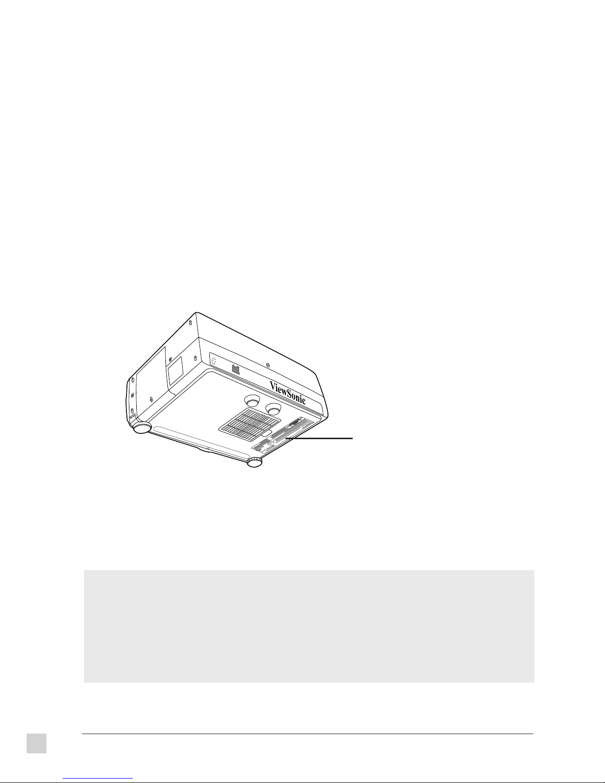
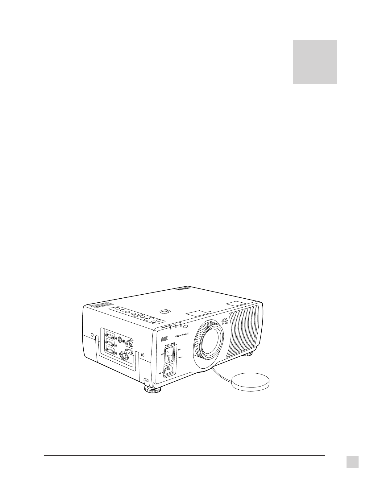
The label on the bottom
of the projector shows the
model number and serial
number. Write the serial
number below.
For your records
The serial number of this product is on the bottom of the monitor. Write the serial number in the space below and
keep this guide as a permanent record of your purchase to aid in identification in the event of theft or loss.
Model Name: ViewSonic PJ820
Model Number: VPRJ21357-2
Serial Number: ______________________
ii
ViewSonic PJ820
Page 4
Safety Guidelines
Caution: Use a power cable that is properly grounded. Always use the AC cords listed
below for each area:
USA . . . . . . . . . . . . . . . . . . . . . . . . UL
Canada . . . . . . . . . . . . . . . . . . . . . CSA
Germany . . . . . . . . . . . . . . . . . . . . VDE
Switzerland . . . . . . . . . . . . . . . . . . SEV
Britain . . . . . . . . . . . . . . . . . . . . . . . BASEC/BS
Japan . . . . . . . . . . . . . . . . . . . . . . . Electric Appliance Control Act
In other areas, use AC cord which meets local safety standards.
FOR EUROPEAN VERSION ONLY
This appliance is supplied with a moulded three pin mains plug for your safety and
convenience. A 13 amp fuse is fitted in this plug. Should the fuse need to be replaced,
ensure that the replacement fuse has a rating of 13 amps and that it is approved by
ASTA or BSI to BS1362. Check for the ASTA mark
or the BSI mark
of the fuse.
If the plug contains a removable fuse cover, you must ensure that it is refitted when the
fuse is replaced. If you lose the fuse cover, the plug must not be used until a
replacement cover is obtained. A replacement fuse cover can be purchased from your
local ViewSonic dealer.
IF THE FITTED MOULDED PLUG IS UNSUITABLE FOR THE SOCKET OUTLET IN
YOUR HOME, THEN THE FUSE SHOULD BE REMOVED AND THE PLUG CUT OFF
AND DISPOSED OF SAFELY. THERE IS A DANGER OF SEVERE ELECTRICAL
SHOCK IF THE CUT OFF PLUG IS INSERTED INTO ANY 13 AMP SOCKET.
If a new plug is to be fitted, please observe the wiring code as shown below. If in any
doubt, please consult a qualified electrician.
WARNING: THIS APPLIANCE MUST BE GROUNDED.
Important: The wires in the main leads are coloured in accordance with the following code:
The colors of the wires in the main leads of this appliance may not correspond with the colored
markings identifying the terminals in your plug. Please comply with the following instructions:
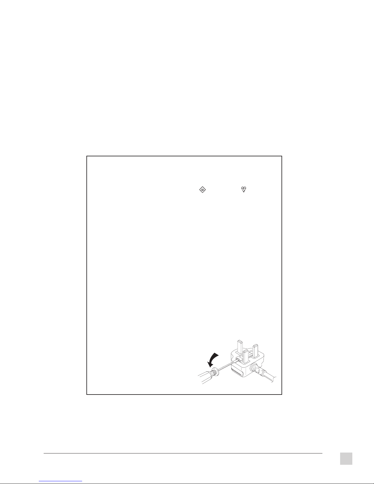
Note: To replace the fuse, open the fuse
Green-Yellow . . . . . . . . . . . . . . . . . . . . . Ground
Blue . . . . . . . . . . . . . . . . . . . . . . . . . . . . Neutral
Brown . . . . . . . . . . . . . . . . . . . . . . . . . . Live
l The Green-Yellow wire must be connected to the Green or Green-Yellow terminals in
the plug marked with the letter E or with the ground symbol.
l The Blue wire must be connected to the Black
terminal in the plug marked with the letter N.
l The Brown wire must be connected to the Red
terminal in the plug marked with the letter L.
compartment with a screwdriver.
on the body
ViewSonic PJ820
iii
Page 5
FCC Information
This equipment has been tested and found to comply with the limits for a Class A digital device, pursuant to part 15 of the FCC
Rules. These limits are designed to provide reasonable protection against harmful interference in a residential installation. This
equipment generates, uses, and can radiate radio frequency energy, and if not installed and used in accordance with the
instructions, may cause harmful interference to radio communications. However, there is no guarantee that interference will not
occur in a particular installation. If this equipment does cause unacceptable interference to radio or television reception, which can
be determined by turning the equipment off and on, the user is encouraged to try to correct the interference by one or more of the
following measures:
l Reorient or relocate the receiving antenna.
l Increase the separation between the equipment and receiver.
l Connect the equipment into an outlet on a circuit different from that to which the receiver is connected.
l Consult your dealer or an experienced radio/TV technician for help.
FCC Warning:
To assure continued FCC compliance, the user must use a grounded power supply cord and the provided shielded
video interface cable with bonded ferrite cores. Also, any unauthorized changes or modifications to this projector
would void the user’s authority to operate this device.
Power Supply Cord
USA
For units with 100-120V input voltage in the USA, use the following:
UL Listed and CSA Certified Type SVT or SJT No. 18/3 AWG rated 125VAC 8A minimum. One end terminated in a molded on
parallel blade, grounding attachment cap or hooded attachment cap (15A, 125V configuration), other end terminated in a molded on
appliance coupler.
CE Certification
This device complies with the requirements of the EEC directive 89/336/EEC with regard
to Electromagnetic compatibility.
Note when handling the power cord
Do not remove the ferrite core which is attached to the accessory power cord. If the ferrite core is removed, electromagnetic
interference may result.
iv
ViewSonic PJ820
Page 6
IMPORTANT SAFETY NOTICE
Warning To prevent damage which may result in fire or shock hazard, do not
expose this appliance to rain or moisture.
The lightning flash with arrowhead symbol within an equilateral
triangle, is intended to alert the user to the presence of uninsulated
“dangerous voltage” within the product’s enclosure that may be of
sufficient magnitude to constitute a risk of electric shock to persons.
The exclamation point within an equilateral triangle is intended to
alert the user to the presence of important operating and maintenance
(servicing) instructions in the literature accompanying the product.
Caution This equipment comes with a three-pin grounding-type power plug,
which is a safety feature. Do not remove the grounding pin on the
power plug. This plug will only fit a grounding-type power outlet.
If you are unable to insert the plug into the outlet, contact an
electrician. Do not defeat the purpose of the grounding plug by
removing it.
Do not remove
For other important safety information, see Chapter 5 Care and Safety Tips.
ViewSonic PJ820
v
Page 7

vi
ViewSonic PJ820
Page 8

CONTENTS
Safety Guidelines . . . . . . . . . . . . . . . . . . . . . . . . . . . . . . . . . . . . . . . iii
FCC Information . . . . . . . . . . . . . . . . . . . . . . . . . . . . . . . . . . . . . . . . iv
1. Getting Started
Package Contents . . . . . . . . . . . . . . . . . . . . . . . . . . . . . . . . . . . . . . . . 1
Features . . . . . . . . . . . . . . . . . . . . . . . . . . . . . . . . . . . . . . . . . . . . . . . . 2
Quick Installation . . . . . . . . . . . . . . . . . . . . . . . . . . . . . . . . . . . . . . . . 3
Projector Views . . . . . . . . . . . . . . . . . . . . . . . . . . . . . . . . . . . . . . . . . . 4
Setting Up the Projector . . . . . . . . . . . . . . . . . . . . . . . . . . . . . . . . . . . 5
Screen Requirements . . . . . . . . . . . . . . . . . . . . . . . . . . . . . . . . . . . . . 6
Standard Setup Positions and Dimensions . . . . . . . . . . . . . . . . . . . . . 7
System Configuration . . . . . . . . . . . . . . . . . . . . . . . . . . . . . . . . . . . . . 8
Side Connector Panel . . . . . . . . . . . . . . . . . . . . . . . . . . . . . . . . . . . . 10
Inserting Batteries into the Remote Control Unit . . . . . . . . . . . . . . 11
Turning the Power On and Off . . . . . . . . . . . . . . . . . . . . . . . . . . . . . 12
2. Operation
The Projector . . . . . . . . . . . . . . . . . . . . . . . . . . . . . . . . . . . . . . . . . . 15
The Remote Control Unit . . . . . . . . . . . . . . . . . . . . . . . . . . . . . . . . . 16
Using the Remote Control Unit as a Wireless Mouse/Pointer . . . . 17
Operating Range of the Remote Control Unit . . . . . . . . . . . . . . . . . 18
Changing the Input Source . . . . . . . . . . . . . . . . . . . . . . . . . . . . . . . . 19
System Format Selection for S-Video Input Signals . . . . . . . . . . . . 21
Switching the Signal Mode During RGB Signal Input . . . . . . . . . . 21
Displaying the On-Screen Menu . . . . . . . . . . . . . . . . . . . . . . . . . . . 21
Resetting Adjustment Values to Factory Settings . . . . . . . . . . . . . . 21
Adjusting the Vertical Position of the Projected Picture . . . . . . . . . 22
Adjusting the Lens . . . . . . . . . . . . . . . . . . . . . . . . . . . . . . . . . . . . . . 23
Changing the Projection Method . . . . . . . . . . . . . . . . . . . . . . . . . . . 24
Adjusting the Picture Setting . . . . . . . . . . . . . . . . . . . . . . . . . . . . . . 25
Adjusting the White Balance . . . . . . . . . . . . . . . . . . . . . . . . . . . . . . 26
Adjusting the Picture Position . . . . . . . . . . . . . . . . . . . . . . . . . . . . . 27
Adjusting the Blanking . . . . . . . . . . . . . . . . . . . . . . . . . . . . . . . . . . . 28
Adjusting the Horizontal Size/Width . . . . . . . . . . . . . . . . . . . . . . . . 29
About Dot Clock Adjustment . . . . . . . . . . . . . . . . . . . . . . . . . . . . . . 30
Adjusting the Audio . . . . . . . . . . . . . . . . . . . . . . . . . . . . . . . . . . . . . 31
Other Useful On-Screen Functions . . . . . . . . . . . . . . . . . . . . . . . . . 33
ViewSonic PJ820 Contents
vii
Page 9

3. Technical Data
Specifications . . . . . . . . . . . . . . . . . . . . . . . . . . . . . . . . . . . . . . . . . . 37
Timing Chart . . . . . . . . . . . . . . . . . . . . . . . . . . . . . . . . . . . . . . . . . . . 39
Using the Serial Connector. . . . . . . . . . . . . . . . . . . . . . . . . . . . . . . . 40
Pin Configuration and Signal Names for RGB Input Connectors . . 42
Accessories . . . . . . . . . . . . . . . . . . . . . . . . . . . . . . . . . . . . . . . . . . . . 42
Parts . . . . . . . . . . . . . . . . . . . . . . . . . . . . . . . . . . . . . . . . . . . . . . . . . . 42
Dimensions . . . . . . . . . . . . . . . . . . . . . . . . . . . . . . . . . . . . . . . . . . . . 43
4. Troubleshooting
Problems, Causes and Solutions . . . . . . . . . . . . . . . . . . . . . . . . . . . . 45
5. Care and Safety Tips
Safety Precautions and Helpful Hints . . . . . . . . . . . . . . . . . . . . . . . 47
Cleaning and Maintenance . . . . . . . . . . . . . . . . . . . . . . . . . . . . . . . . 49
Warranty . . . . . . . . . . . . . . . . . . . . . . . . . . . . . . . . . . . . . . . . . . . . . . 54
Index . . . . . . . . . . . . . . . . . . . . . . . . . . . . . . . . . . . . . . . . . . . . . . . . . 55
viii
Contents
ViewSonic PJ820
Page 10
GETTING STARTED
Package Contents
TM
Congratulations on purchasing a ViewSonic PJ820 Office Theater
package includes:
TM
l
ViewSonic PJ820 Office Theater
l
Video cable with 15-pin high density (HD) mini D-sub connector
l
Remote control
l
Two AA batteries
l
PS/2 mouse cable with 13-pin round connector for PC
l
9-pin serial mouse cable with 13-pin round connector for PC
l
AC power cable
l
A/V cable
l
Lens cap
l
User’s guide
l
Software diskette or CD-ROM which includesViewSonic® monitor installation file (VS*.inf) for
Windows® 95 (required for Plug & Play).
Important!
Save the original box and all packing material for future shipping needs.
LCD projector
LCD projector! Your ViewSonic PJ820
1
ViewSonic PJ820
Getting Started
1
Page 11

Features
Superior Image ...
l
The three-panel active matrix LCD designed with 750 ANSI lumens* projects an exceptionally
bright and sharp image with true 16.7 million colors, out-performing most one-panel LCD or onechip DLP projectors.
l
The high contrast ratio provides sharp, crisp images that are legible even in a well lit room.
l
Advanced video compression ensures a sharp image with all the detail and lines present after
compression.
l
The optical advanced prism uniformity system ensures maximum brightness and sharpness
throughout the screen without any dark corners or edges (by actively converting P-Polarized lights to
S-Polarized light.)
System Flexibility ...
l
Equipped with DDC1TM and DDC2BTM for Plug & Play compatibility with both new and legacy
computers, saving setup time.
l
The wireless pointer/remote control maximizes the presenter's effectiveness by combining an
infrared pointer with a wireless remote to adjust both projected image and audio, eliminating
confusion caused by two handheld devices.
l
Up to three input sources in a variety of formats are supported, including NTSC, PAL, SECAM, and
S-Video.
l
Muting functions can be accessed from the projector and from the remote control enabling the
presenter to easily mute video and audio.
l
True SVGA resolution ensures images from a wide variety of applications are projected with true
fidelity, compatible with computers that support from VGA up to 1,024 x 768** resolution.
Ergonomic Design ...
l
At 21.6 pounds (9.8 kg.) the projector is lightweight and portable.
l
The contour of the wireless pointer/remote control fits comfortably in the hand.
Environmentally Friendly ...
l
All plastic parts are recyclable. All materials are strictly selected for ease of maintenance,
inspection, and disposal.
l
Our shipping cartons are made of recyclable material.
* Maximum brightness varies with lamp age and environmental conditions.
** 1024 x 768 (advanced video compression).
2
Getting Started
ViewSonic PJ820
Page 12
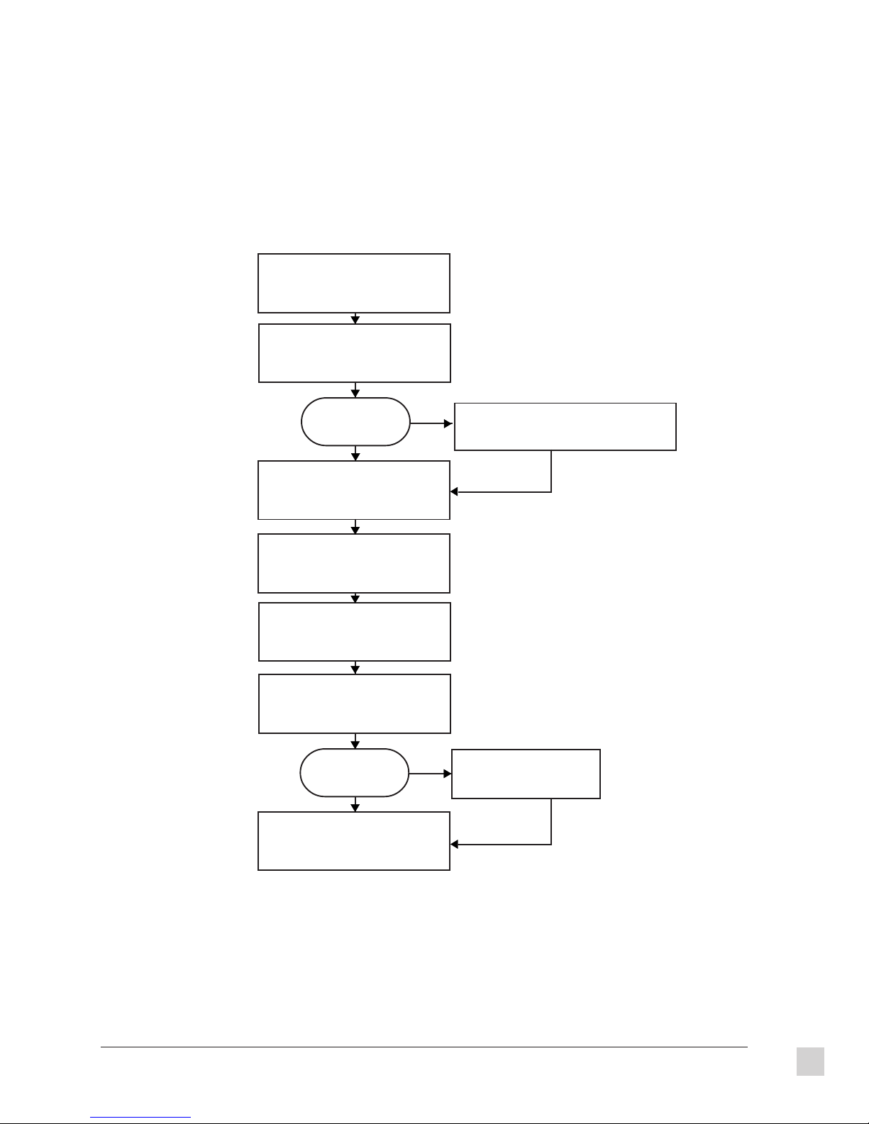
Quick Installation
Look for the serial number on the bottom
of the PJ820 Projector. Please write it in
the space provided (page ii, For your
1
records) in front of the user’s guide.
Read the user's guide thoroughly before
installing the projector. Before connecting
the projector, be sure all video and audio
2
sources are turned off.
If one of the sources
is a computer, is it an
IBM® or compatible?
Ye s
Connect the audio and video signal
source(s), such as computer(s), VCR(s),
Laser Player(s), audio system, etc.
3
following the instructions on the next
pages.
Turn all audio and video sources on.
Then, turn the PJ820 LCD Projector
4
on.
If error message “No Signal” appears,
See Troubleshooting (Chapter 4).
5
Adjust user controls according to
personal preference. (see Chapter 2)
6
6
Is the image
satisfactory?
Ye s
Installation is complete.
Enjoy your new PJ820
Color LCD Projector!
No
No
Macintosh® users, contact ViewSonic® (see
Chapter 4) to order a ViewSonic Macintosh Kit
2
a
(Part No. PJMAC1).
See
a
Troubleshooting
(Chapter 4).
6
ViewSonic PJ820
Getting Started
3
Page 13
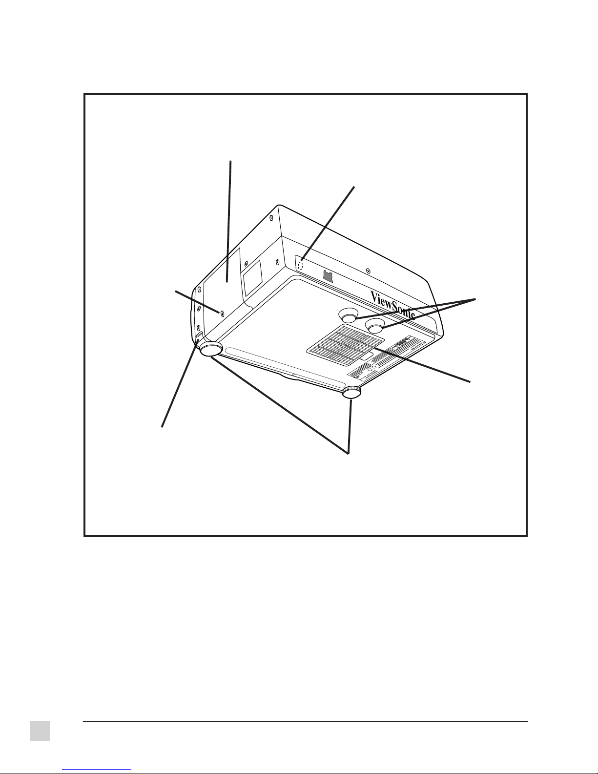
Projector views: back, bottom, side
Lamp unit cover
to access lamp
Side
Screw for removing
the lamp unit cover
to replace the lamp
Remote control signal receptor
receives infrared signals from Remote
Control Unit
Back
Fixed legs
Adjuster button unlocks the
adjustable legs
Front
Air filter
Adjustable legs (two) adjusts the angle of
inclination of the projector
4
Getting Started
ViewSonic PJ820
Page 14
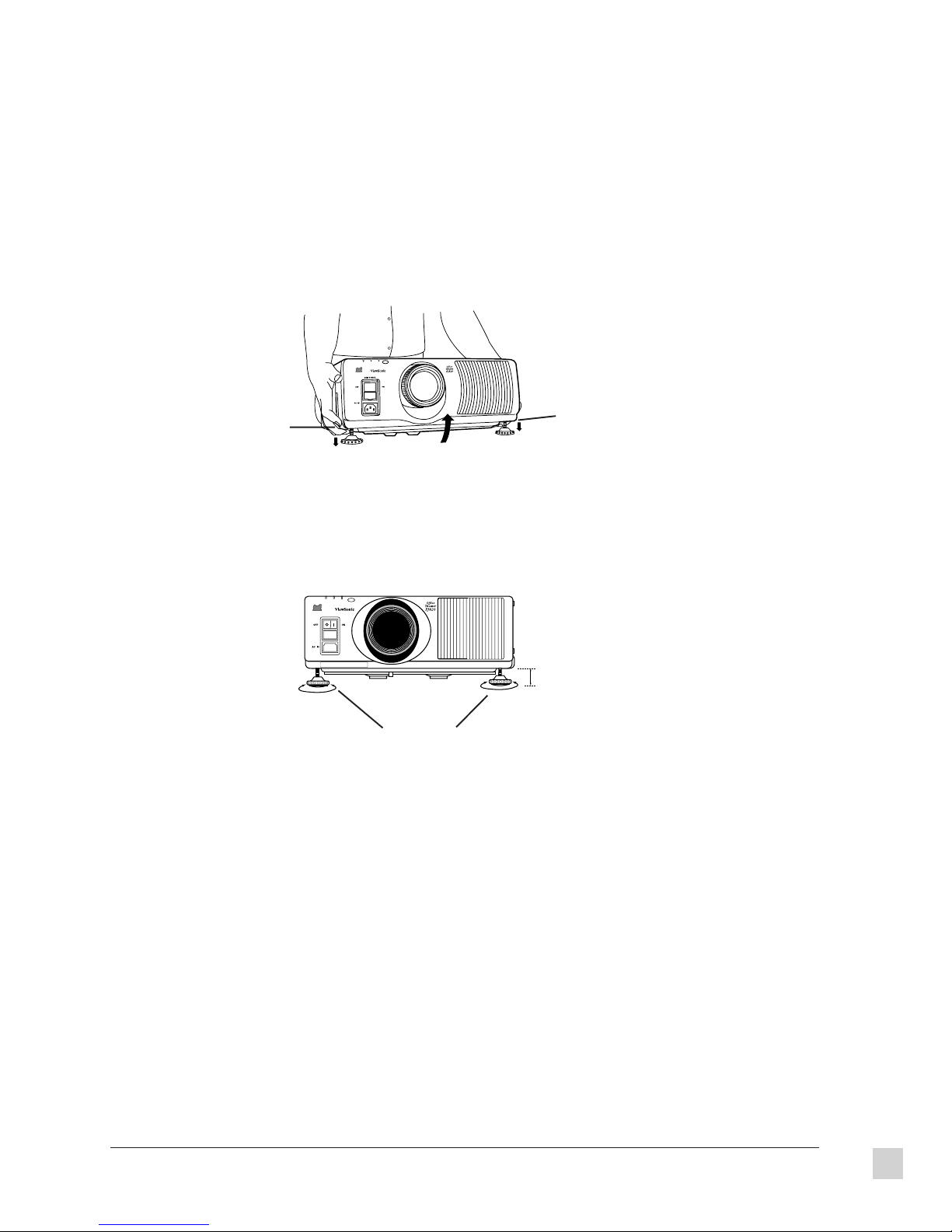
Setting up the projector
The projector must be horizontal to get a distortion-free picture. Place the projector on a tabletop or similar
surface and follow the procedure below to ensure that no distortion of the picture occurs. Also see page 22.
1 Lift the front of the projector until the bottom of projector is a few inches above the tabletop. While holding
it in this position, press the adjuster buttons under the sides of the projector (one at left and right corners).
The left and right adjustable legs drop down until they reach the setup surface.
NOTE: Do not release the buttons until both legs have reached the setup surface.
Adjuster
button
Adjuster
button
2 Release the adjuster buttons. The adjustable legs lock into place as the buttons are released.
Up to 2 3/8" (60mm)
Adjustable legs
3 Turn the adjustable legs by hand in either direction to make fine adjustments to the level of the projector so
that the projector is perfectly horizontal. The legs can be extended by up to 2 3/8" (60 mm). If you try to
extend them any further than this, they spin freely.
To retract the legs:
1 Hold the projector firmly while lifting the front of the projector slightly.
2 Press and hold the adjuster buttons.
3 Gently lower the projector.
ViewSonic PJ820
Getting Started
5
Page 15

Screen requirements
The ViewSonic PJ820 projects images onto flat screens. However, the brightness and viewable range varies
with each type of screen. Selecting a screen with characteristics that are suitable for the intended use is
important.
Screen Type
Polarized screen
White screen
Silver screen
FRONT Reflective Screens
Ceiling
Screen Characteristics
Because the surface of the screen has been treated to make it
polarized, it will only reflect light from a single direction.
Consequently, if you use such a screen with an LCD projector, a
clear image can be obtained even in bright rooms because the
screen hardly reflects any extraneous light.
This type of screen can be seen from anywhere, so there are no
limits on the viewing position. However, the surrounding walls
should be darkened as in a movie theater, otherwise a clear picture
cannot be obtained.
This type of screen is recommended when the projector is
suspended from the ceiling. This type of screen gives a picture 2-4
times brighter than a white screen. A variety of types are available
from different manufacturers, and each type has different
brightness characteristics. Some also have restrictions on the
possible range of viewing positions.
Beaded screen
Maximum
brightness
Flexible
translucent screen
Rigid-type
translucent screen
REAR Translucent
Screens
Maximum
brightness
Reduced
brightness
Care should be taken with screens that have a high gain, as these
types of screen can cause color distortion at the left and right
edges.
This type of screen is recommended when the projector is placed
on the floor. This type of screen is similar to the silver screen,
except that no color distortion occurs at the left and right edges.
Moreover, most of the light is reflected at the same angle as the
angle of incidence.
Floor
This type of screen is made of PVC (polyvinyl chloride). It has the
same characteristics as silver screens, but sometimes has hot spots.
This type of screen is made of acrylic plastic. It is extremely
durable and has excellent optical characteristics. It performs the
same as silver screens.
6
Getting Started
ViewSonic PJ820
Page 16
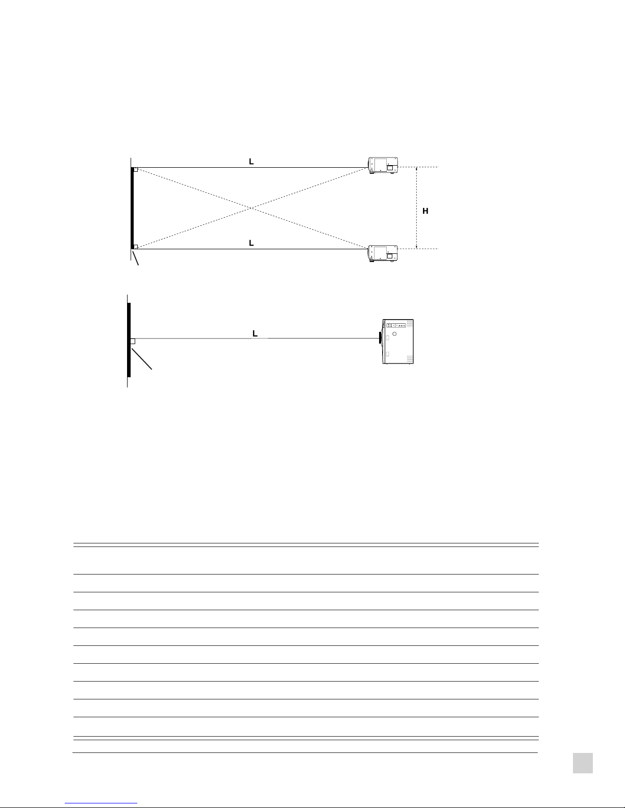
Standard setup positions
The illustrations and standard setup dimensions below help you determine where to set up the projector.
Distance L from the projector to the screen and the height H do not vary, regardless whether the floor, table or
ceiling are used to set up the projector, or whether a front or rear projection screen is used.
Ceiling mount
Side
View
Projected image
Lower edge of projected image
Table mount
Top
View
Projected image
L: Projection distance
H: Height from lower edge of projected image to center of lens
Standard setup dimensions
The further away the projector is from the screen, the bigger the picture is (image as shown in the table below).
See also the table of screen requirements in this chapter with descriptions of various types of screens. These
descriptions will help you determine whether to set up in front of or behind the screen and where to set up in
the room. The projector uses a x 1.5 electronic zoom lens for adjusting the projection distance. You can also
move the lens up or down. For instructions on adjusting the lens, the front of the projector, and focusing the
image, see the Chapter 2 Operation. When the projector is not completely vertical with the screen and
horizontal to the floor, the projected image distorts. The values in the table below are approximate.
Projection size Projection distance (L) Height from lower edge of
Minimum Maximum projected image to center of lens (H)
30 3’3" (1.0m) 4’11" (1.5m) 0-18" (0-0.457m)
40 4’7" (1.4m) 6’6" (2.0m) 0-24" (0-0.610m)
60 6’10" (2.1m) 10’2" (3.1m) 0-36" (0-0.914m)
80 9’2" (2.8m) 13’9" (4.2m) 0-48" (0-1.219m)
100 11’9" (3.6m) 17’4" (5.3m) 0-60" (0-1.524m)
150 17’8" (5.4m) 26’2" (8.0m) 0-90" (0-2.286m)
200 23’7" (7.2m) 35’1" (10.7m) 0-120" (0-3.048m)
250 29’6" (9.0m) 43’11" (13.4m) 0-150" (0-3.810m)
300 35’5" (10.8m) 53’1" (16.2m) 0-180" (0-4.572m)
ViewSonic PJ820
Getting Started
7
Page 17

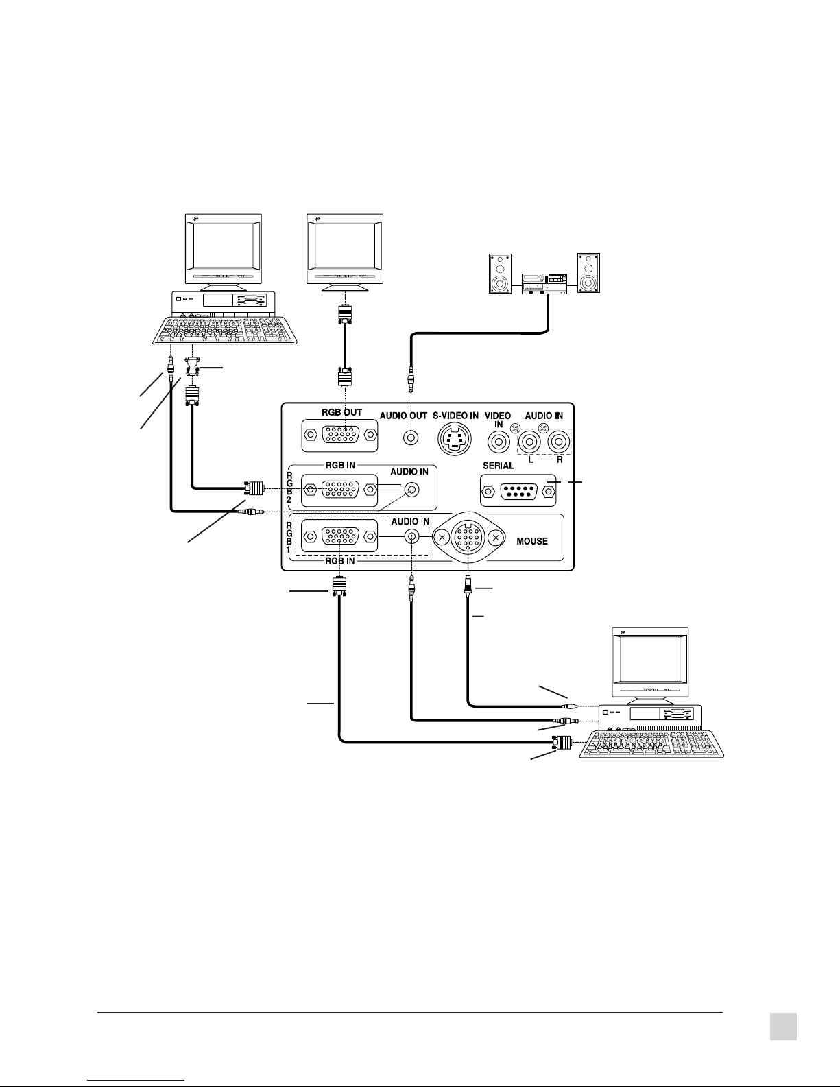
System configuration
• Turn off the power supply of each system component before connecting any of the components.
• Read the instruction manual for each system component before connecting it.
• If there is a lot of jitter in the video signal input from the video source, the picture on the screen may
flicker. In such cases, it will be necessary to connect a TBC (time base corrector).
• The projector can be connected to video signal sources which output VIDEO, S-VIDEO and analog RGB
signals (0.6-8.0 Vp-p synchronized signals).
• The projector has built-in speakers. However, you will need to connect a separate audio system to the
AUDIO OUT terminal if your needs specify high sound volumes. No sound will come out of the projector’s
built-in speaker while the AUDIO OUT terminal is being used.
Audio system
Laser disc player
This serial port
allows you to
control the
projector.
VCR
Side Connector Panel
Connecting to audio-visual equipment
In the above diagram, if the S-VIDEO IN and VIDEO IN connectors are both used at the same time, the SVIDEO IN signal input has priority. To view the signal being input to the VIDEO IN connector, disconnect the
plug from the S-VIDEO IN connector.
Only one audio signal input is available for S-VIDEO or VIDEO signals. Select one or the other.
If the video signal source is connected using a cable with a BNC junction plug, use a BNC/RCA adapter to
convert the pin jack.
If an audio system is connected to the AUDIO OUT connector, the sound volume balance and muting can be
controlled by the Remote Control Unit which is supplied with the projector. However, if the volume is set to
“0”, no audio signal will be output from the AUDIO OUT connector.
8
Getting Started
ViewSonic PJ820
Page 18
An Example of Computer Connections
MonitorComputer
Audio system
To audio
output
terminal
To video
output
connector
D-SUB 15-pin
(male)
ViewSonic
1 2
Macintosh* adapter
(accessory)
D-SUB 15-pin
(male)
ViewSonic
1 2
This serial port allows you
to control the projector
13-pin (male)
PC mouse cable (for
PS/2 or serial)
Computer
To mouse connector
RGB signal cable
(VGA)
To video output terminal
To video output connector
ViewSonic
1 2
*Macintosh computers require a ViewSonic Macintosh Compatibility Kit. Contact ViewSonic (See Chapter 4
Troubleshooting for contact details) to obtain the kit.
NOTE: For instructions on using the Remote Control Unit in place of the computer’s mouse see Operations
Chapter 2. Make sure to turn on the main power to the projector before turning on the personal computer. If
using a personal computer with a suspend/resume function, the infrared mouse function may not operate until
the computer is restarted. This function operates only when input to the RGB 1 connector has been selected.
For details about the pin configuration for the RGB connector and what kinds of computers can be connected
to the projector see Specifications Chapter 3.
ViewSonic PJ820
Getting Started
9
Page 19
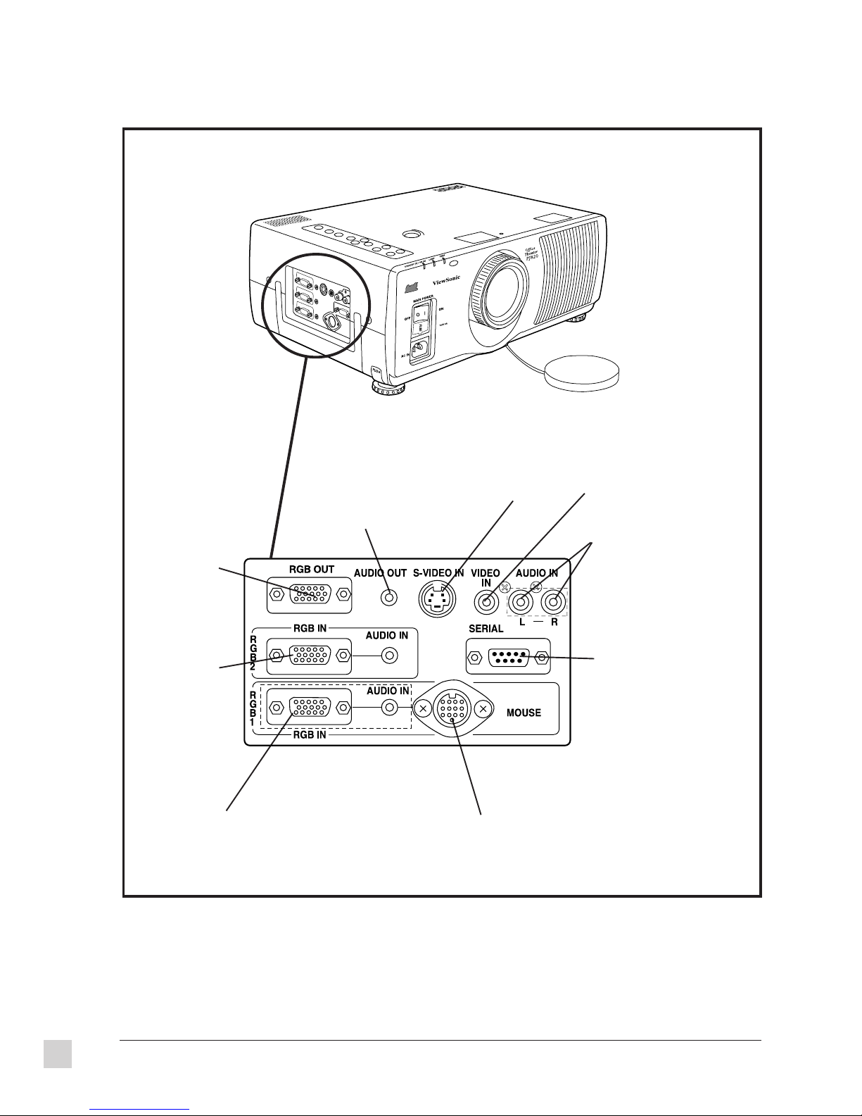
Side Connector Panel
RGB OUT connects
to a monitor for
output from RGB1
or RGB2
RGB 2 (RGB IN/
AUDIO IN) input
RGB and audio
signals
RGB 1 (RGB IN/AUDIO IN) input
RGB and audio signals
AUDIO OUT (stereo mini)
connector that provides
audio output for the
selected audio input
source
Side Connector Panel
S-VIDEO IN
MOUSE connector to connect an accessory or separate
mouse cable, allowing you to operate a personal computer
with the pointer/cursor button then click buttons on the
Remote Control Unit instead of using a mouse
VIDEO IN terminal to
input composite video
signals
AUDIO IN (L-R)
connectors for S-VIDEO/ VIDEO
input and corresponding audio
signals for the VIDEO IN or SVIDEO IN terminal
SERIAL connector to connect
a computer to the projector for
external control of the projector
10
Getting Started
ViewSonic PJ820
Page 20
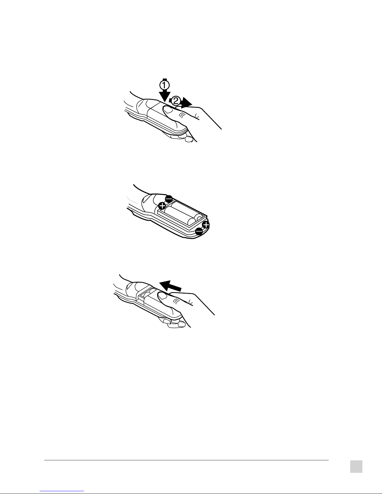
Insert batteries before using the Remote Control Unit
1 Open the battery compartment cover. Push the marked cover down firmly and pull toward you to remove it.
2 Insert two AA batteries so their direction matches the polarity markings inside the compartment. Do not use
rechargeable (Ni-Cd) batteries.
3 Close the battery compartment cover.
More about the batteries
To prevent damage to or leaking of the batteries, follow these safeguards:
Replace both batteries at the same time.
Do not mix old and new batteries or batteries of different types (such as alkali and manganese batteries).
Do not burn spent batteries or put them in with combustible garbage.
Do not short-circuit a battery (connecting positive to negative).
Do not open a battery (with a tool like a screwdriver).
Do not recharge disposable batteries.
ViewSonic PJ820
Getting Started
11
Page 21
Turning the power On and Off
CAUTION: If the MAIN POWER switch on the projector is pressed while the cooling fan is still
operating, the operating life of the projector lamp will be shortened. Be sure to follow the procedures
given below when turning the projector power on and off.
Power indicator
Power button
Power button
Main power switch
Turning the power On
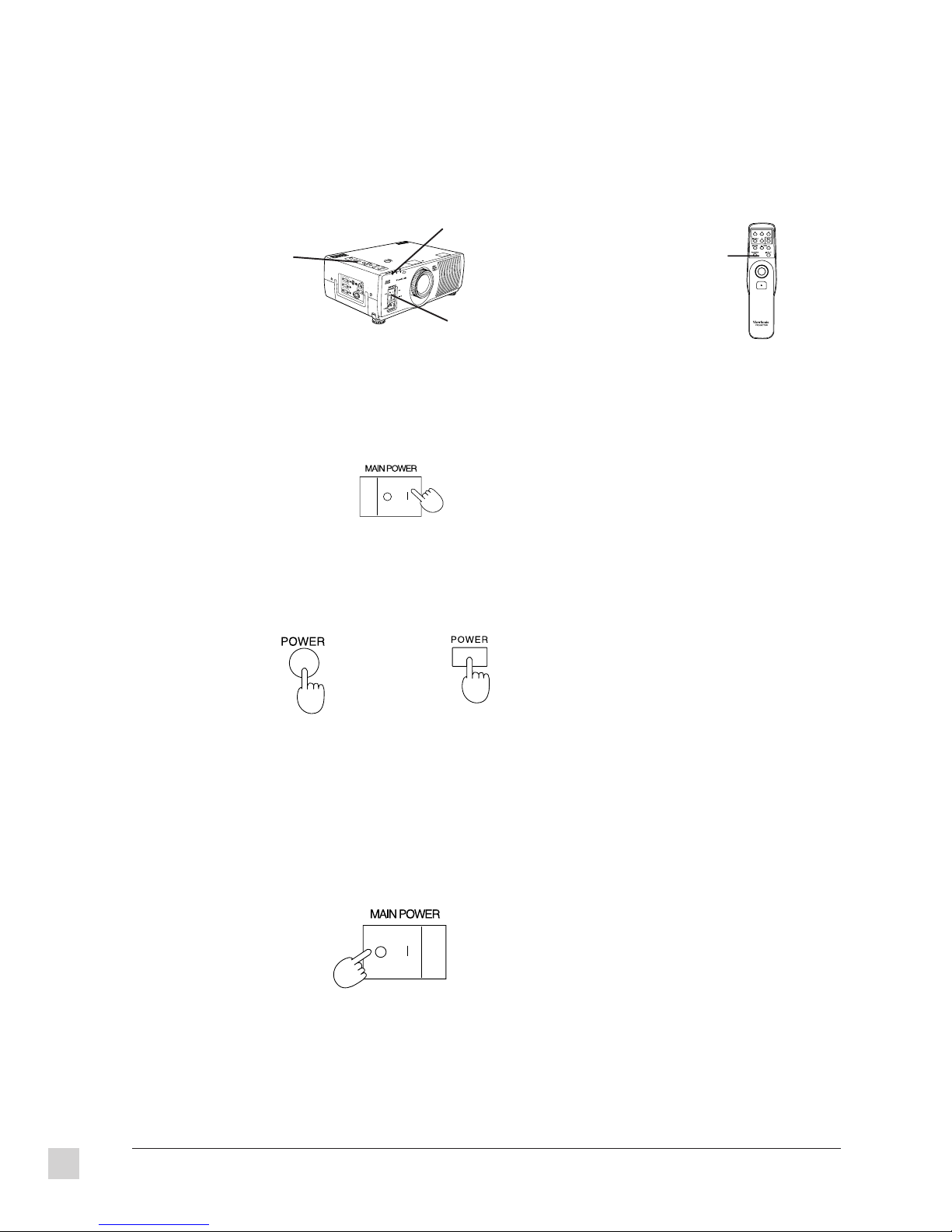
1 Press the MAIN POWER switch on the projector to the ON (|) position. The power indicator turns red and
the projector switches to Standby Mode.
Projector
2 Press the POWER button on either the top of the projector or on the Remote Control Unit. The power
indicator alternates between green and orange. When it stops at green, a picture is projected onto the screen
after about 15 seconds.
Projector
Remote control
12
Turning the power Off
1 Press the POWER button on either the top of the projector or on the Remote Control Unit. The power
indicator turns red and the projector switches to Standby Mode.
2 Wait approximately 90 seconds until the cooling fan stops.
3 Press the MAIN POWER switch to the OFF (O) position. The power indicator switches off.
Projector
CAUTION: Do not turn the MAIN POWER switch to the OFF position, unplug the power cord from the
wall socket, or shut off the main power supply until the cooling fan stops.
NOTE: If the power is turned off using the POWER button, the cooling fan continues to operate
approximately 90 seconds while the inside of the projector is still at high temperature.
Continued
Getting Started
ViewSonic PJ820
Page 22

Turning the power On and Off (continued)
If not using the projector for long periods of time, turn the MAIN POWER switch at the front of the projector
to the OFF position.
If you press the POWER switch accidentally while the projector is being used and then immediately turn the
power back on, the picture may not appear.
The REMOTE POWER function may cause the operation of the POWER button on the Remote Control Unit to
be disabled temporarily.
If you turn off the POWER button while leaving the MAIN POWER switch on, the projector still draws
approximately 8 Watts of power, even though the fan has stopped.
If the lamp does not turn on right away, the power indicator flashes between green and orange for 30 seconds.
Then the projector automatically attempts to turn on the lamp again.
The projector is equipped with a lens retracting function which activates automatically when the power is
turned off. However, the lens will not return to the previous position even if the power is turned back on again.
To disable this function, see the section on “Using the lens retracting function.”
ViewSonic PJ820
Getting Started
13
Page 23

14
Getting Started
ViewSonic PJ820
Page 24

OPERATION
2
This chapter describes how to use the functions of the ViewSonic PJ820 Office TheaterTM. You can access
various functions by using buttons on both the projector and the Remote Control Unit. Select functions also
from the on-screen control menu projected on the screen. For instructions on setting up the projector, see
Chapter 1 Getting Started.
The Projector
POWER button
turns picture
image on and off
Select the input signal
source: VIDEO, RGB1,
RGB2 (See Specifications
in Chapter 3)
Built-in stereo speakers
Pull out carrying
handle
Side Connector Panel
MAIN POWER switch turns the
projector power on and off
Select menu options
and change setting
values
MENU button turns menu
screen on and off and
returns to previous
screen
Picture focus
ZOOM adjustment +/- buttons
adjusts picture size
LENS SHIFT dial moves the lens up and down
to make fine adjustments to the lens position
Remote control signal receptor receives
signal transmissions from Remote Control
Unit
Focus ring to adjust the image
focus
Air outlet port
Projection lens enlarges the
image and projects it onto the
screen
Lens cap
TEMP indicator illuminates or flashes as a warning if the temperature inside the projector reaches an abnormal level
Fuse holder for a 125
VAC, 8 A fuse
Power input socket (AC IN) for the
power cord supplied with the
projector
ViewSonic PJ820
LAMP indicator illuminates when the useful life of the lamp is coming to an
end and flashes when there is a problem with the lamp unit
Power indicator STAND BY turns red when the projector is in standby mode, green
when the projector is on, and orange when in standby mode and the cooling fan is
operating
Operation
15
Page 25

The Remote Control Unit
The Remote Control Unit has two main uses: a device to select projector functions (explained below) and a
wireless mouse/pointer (explained on the next page).
Arrow buttons (Up, Down, Left,
Right) select items from the
menu screen and change setting
values
MENU button turns the display of the
menu screen on and off and returns
display to the previous screen
MUTE button temporarily turns off the
sound. This button also temporarily
turns off the picture together with the
sound
POWER button turns projection of
the picture on and off
Standard (STD) button resets the
picture adjustment values to the factory
pre-settings
Volume adjustment buttons (VOL +/-) adjust
the volume of the sound from the built-in
speaker and the output level from the AUDIO
OUT terminal
INPUT select button selects the
input signal source
Pointer button moves the computer's
mouse cursor on-screen
Click button 2 corresponds to the right
button on a standard mouse with two
buttons
Transmitter transmits infrared signals
Click button 2
Click button1 corresponds to the button
on a single-button mouse, or to the left
button on a standard mouse with two
buttons
Battery compartment cover
CAUTION
Do not place the Remote Control Unit upside down on a flat
surface. This may cause the pointer button to be pressed which
reduces the life of the batteries.
16 ViewSonic PJ820Operation
Page 26

Using the Remote Control Unit as a wireless mouse
Front
Back
You can also use the Remote Control Unit as a wireless mouse in place of a mouse connected to a personal
computer. When you move the pointer button with your thumb, the cursor moves on the screen, also acting as a
pointer. This is made possible by an infared beam from the remote contol unit that bounces off the screen, back to
an infared sensor on the projector.
Pointer button
To use this feature, connect the mouse port on the projector to the
mouse port on the computer with the mouse cable supplied with the
projector. See Chapter 1 for more information about connecting the
mouse cable.
NOTE: The wireless mouse only operates when you use the RGB 1
connector on the projector.
Click button 2
Click button 1
This projector's mouse feature is compatible with the following types
of mouse ports:
PC Serial mouse port
PS/2 mouse port
®
Top View
Macintosh
Side View
mouse port
NOTE: If strong light shines onto the remote control signal receptor, or if there are any obstacles between the
remote control signal receptor on the projector and the Remote Control Unit, correct remote control operation
may not be possible. Important! The operating range of the Remote Control Unit is limited by the amount of
light reflection loss caused by the characteristics of the screen.
Click button 1
Button 1 shown above acts like a mouse button on a one button mouse or the left button on a standard mouse
with two buttons.
Click button 2
Button 2 shown above corresponds to the right button on a standard mouse with two buttons.
Pointer button
Point the Remote Control Unit at the center of screen. As you move your thumb on the pointer button the
mouse cursor moves on the screen accordingly (shown below).
ViewSonic PJ820
Operation
17
Page 27

Operating range of the Remote Control Unit
Point the Remote Control Unit toward the receptor on the front or the rear of the projector. Refer to the
illustrations below for the operating range of the Remote Control Unit.
Rear signal receptor
23.0 ft. (7.0m)
Remote
control
Remote
control
23.0 ft. (7.0m)
Top View
Front signal receptor
Front signal receptor
Rear signal receptor
23.0 ft. (7.0m) 23.0 ft. (7.0m)
Side View
Remote
control
Remote
control
18 ViewSonic PJ820Operation
Page 28
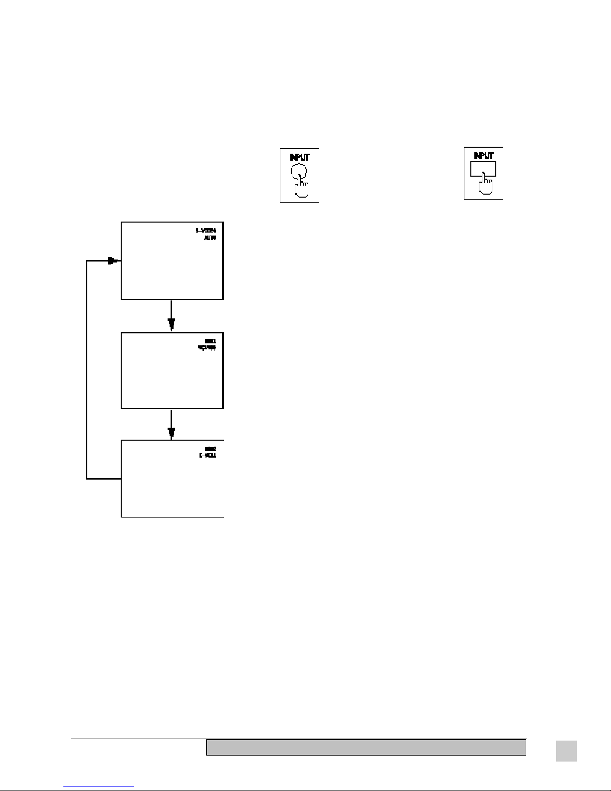
Changing the input source
You can select both the video and the corresponding audio signal input sources by pressing the INPUT button
on the projector or the Remote Control Unit. The input source you select appears on the screen for
approximately five seconds.
Projector Remote Control Unit
OR
The video signal from the input signal source which is connected to
the S-VIDEO/VIDEO IN connector appears.
The audio from the video source needs to be connected to the
AUDIO IN (L-R) connectors for S-VIDEO/VIDEO input (page 8).
However, only one audio input is available at one time. If you wish
to change the audio input source, you will need to remove and
insert the appropriate plugs.
The signal for RGB1 will be projected. The audio output will be the
signal which is connected for RGB 1.
The signal for RGB 2 will be projected. The audio output will be the
signal connected for RGB 2.
NOTE: The mode name for the currently-selected signal or the name of the signal format will be displayed
directly underneath the on-screen display of the input signal source
The on-screen display of the selected input source normally appears when projection starts, and also when the
input source is being switched. However, if the input display setting (INPUT DISP) has been turned off, this
on-screen display will not appear.
If the S-VIDEO IN and VIDEO IN connectors are both connected, the S-VIDEO input will automatically be
given priority. If you wish to view the signal being input to the VIDEO IN connector, disconnect the plug from
the S-VIDEO IN connector.
If the picture is not projected normally when an RGB signal is being input, you will need to switch the signal
mode to match the input signal.
If S-VIDEO or VIDEO has been selected as the input signal source, it may be necessary to select the correct
format which corresponds to the input signal.
ViewSonic PJ820
Operation
19
Page 29

System format selection for S-VIDEO input signals
If S-VIDEO or VIDEO has been selected as the input signal source, there may be times where the signal
format is not selected correctly resulting in an unclear projected picture. If this happens, select the correct
signal format as follows: (the default setting is AUTO)
1 Press the MENU button to display the MENU screen.
2 Press the /\ or \/ button to select PICTURE.
3 Press the < or > button to display the PICTURE screen.
4 Press the /\ or \/ button to select TV-SYSTEM.
5 Press the < or > button to select either AUTO, NTSC, PAL,
SECAM, or NTSC 4.43.
Select the appropriate signal from the table below.
Horizontal scanning frequency [kHz] Vertical scanning frequency [Hz] Color subcarrier frequency [MHz]
AUTO Automatically selects NTSC, PAL, SECAM or NTSC 4.43.
NTSC
NTSC 4.43 4.43
PAL
SECAM 4.25 or 4.41
15.7 60.00
15.63 50.00
3.58
4.43
NOTE: The correct signal format may not be selected if, for instance, you are using a poor-quality signal source,
such as a dubbed video tape. Switching the signal format may give better results in such cases.
The setting screen and the MENU screen can both be cleared by pressing the MENU button.
20 ViewSonic PJ820Operation
Page 30

Switching the signal mode during RGB signal input
If the picture is not projected normally when the selected input source is RGB 1 or RGB 2, then select the correct
signal mode by the procedure below.
NOTE: The factory setting is AUTO, so the projector can usually be used without the need to change this setting.
1 Press the MENU button to display the MENU screen.
2 Press the /\ or \/ button to select PICTURE.
3 Press the < or > button to display the PICTURE screen.
4 Press the /\ or \/ button to select “SIGNAL MODE”.
5 Press the < or > button to switch the signal name.
Displaying the on-screen menu
To display the menu screen press the MENU button on the projector
or the Remote Control Unit. The MENU screen shown on the left
appears.
NOTE: If the MENU button is pressed while an on-screen display is
already appearing, the on-screen display will return to the
previously-displayed screen each time the MENU button is pressed.
If it is pressed while the MENU screen shown at left is being
displayed, the MENU screen will be cleared.
Resetting adjustment values to the factory settings
(standard values)
If you press the STD (Standard) button on the Remote Control Unit
while the PICTURE screen, POSITION screen, AUDIO screen or
one of the adjustment screens is displayed, the adjustment settings
will reset to the factory settings.
If the STD (Standard) button on the Remote Control Unit is pressed
while the PICTURE screen, POSITION screen or AUDIO screen is
being displayed, the letters STD will be displayed in yellow in the
top-right corner of the screen and all items displayed will be reset to
the factory settings.
NOTE: However, the TV-SYSTEM and SIGNAL MODE settings in
the PICTURE screen and the VOLUME setting in the AUDIO screen
will not return to the factory settings.
If the STD (Standard) button on the Remote Control Unit is pressed
while one of the individual adjustment screens is being displayed,
the value and the bar display will appear yellow and only the item
displayed will be reset to the factory setting.
ViewSonic PJ820
Operation
21
Page 31

S
o
l
i
d
l
i
n
e
:
O
r
i
g
i
n
a
l
p
i
c
t
u
r
e
p
o
s
i
t
i
o
n
D
o
t
t
e
d
l
i
n
e
:
P
i
c
t
u
r
e
p
o
s
i
t
i
o
n
a
f
t
e
r
a
d
j
u
s
t
m
e
n
t
Adjusting the vertical position of the projected picture
You can adjust the position of the projected picture vertically by turning the LENS SHIFT dial on top of the
projector. Turning the dial clockwise shifts the projected picture higher on the screen; turning it
counterclockwise shifts it lower. To adjust the vertical position of the projected picture:
After determining the distance and the setting-up position, adjust the
vertical position of the projected picture by carrying out the
following procedure.
1 Press the LENS SHIFT dial on top of the projector. The dial pops
up so you can turn it to make adjustments.
• clockwise raises projected picture
• counterclockwise lowers projected picture
2 Press the LENS SHIFT dial down. The dial pops back in again
and adjustment is disabled.
Top View
NOTE: The height of the projection lens can be adjusted within a range of +/- 25/64 inches (+/- 10.1 mm).
However, the adjustment range for the position of the picture will vary depending on its size.
For more information on Front and Rear Screen Requirements, see Chapter 3 Technical Data.
22 ViewSonic PJ820Operation
Side View
Side View
Page 32

Adjusting the lens
An electronic zoom and focusing mechanism allow you to zoom and focus easily by pressing the ZOOM (+/-)
and FOCUS (+/-) buttons on top of the projector or using the on-screen display. Another way to adjust the
focus is by physically turning the lens. If you press both +/- buttons while the on-screen display for other
functions are displayed, the buttons pressed will operate. However, the on-screen display does not switch to the
ZOOM or FOCUS adjustment screen. As a result, operation and display may not match.
To adjust the lens directly
1 Press the ZOOM (+/-) buttons on the top of the projector to
adjust the size of the picture.
+ enlarges the picture
- condenses the picture
2 Press the FOCUS (+/-) buttons on top of the projector to focus
the picture.
NOTE: If approximately five seconds pass without any buttons
being pressed, the adjustment screen will clear.
To adjust the lens using the on-screen display:
1 Press the MENU button to display the MENU screen.
2 Press the /\ or \/ button to select ZOOM on the menu.
3 Press the < or > button to display the ZOOM adjustment
screen.
4 Press the < or > button to adjust the picture size.
+ enlarges the picture
- condenses the picture
5 Press the MENU button, or wait approximately five seconds
without pressing any button. The display returns to the MENU
screen.
6 Press the /\ or \/ button to select FOCUS.
7 Press the < or > button to display the FOCUS adjustment
screen.
8 Press the < or > button to adjust the picture focus.
+ enlarges the picture
- condenses the picture
NOTE: After approximately five seconds without pressing any buttons, the display returns to the MENU
screen. The projector retracts automatically when the power is turned off. However, the lens will not return to
the previously adjusted position even if the power is turned back on again. To disable this function refer to
“Using the lens retracting function” in this chapter.
ViewSonic PJ820
Operation
23
Page 33

Changing the projection method
You have the option of setting up the projector either for front or rear screen projection. To do this you must
select either FRONT or REAR “projection method” from the on-screen display. At the time of shipment from
the factory, the projector was set to the FRONT projection method. To change the projection method:
1 Press the MENU button to display the MENU screen.
2 Press the /\ or \/ button to select OPTION.
3 Press the < or > button to display the OPTION screen.
4 Press the /\ or \/ button to select SET UP.
5 Press the < or > button to display the SET UP screen.
6 Press the /\ or \/ button to select FRONT/REAR.
7 Press the < or > button to select FRONT or REAR.
NOTE: If approximately five seconds pass without any buttons being pressed, the display will return to the
MENU screen. The adjustment screen and the MENU screen can both be cleared by pressing the MENU
button.
FRONT mounting
(Pre-set condition from the factory)
REAR mounting
24 ViewSonic PJ820Operation
Page 34

Adjusting the picture setting
You can adjust the picture settings for any of the selected input signal sources. The items which can be adjusted
vary depending on the type of input signal. The adjustment procedure below describes the on-screen displays
when a signal is being input to the S-VIDEO IN or the VIDEO IN connectors. To make color adjustments:
1 Press the MENU button to display the MENU screen.
2 Press the /\ or \/ button to select PICTURE.
3 Press the < or > button to display the PICTURE screen.
4 Press the /\ or \/ button to select COLOR. If the STD
(Standard) button is pressed while the PICTURE screen shown on
the left appears, the letters STD turn yellow in the top-right corner
of the screen and all settings other than the TV-SYSTEM setting
reset to the factory settings. The values and bar displays for items
which have returned to the factory settings turn yellow.
5 Press the < or > button to display the COLOR individual
adjustment screen.
6 Continue pressing the < or > button to adjust the color. The
current setting will be displayed on the screen by numerals and a
bar. The adjustment operation and the changes made will vary
depending on which adjustment item is selected. Refer to the
table below for details.
Adjustment Item
COLOR
TINT
BRIGHTNESS
CONTRAST
SHARPNESS
Button
Press the > button
Press the < button
Press the > button
Press the < button
Press the > button
Press the < button
Press the > button
Press the < button
Press the > button
Press the < button
Adjustment Details
The color becomes darker
The color becomes lighter
Flesh tones become greenish
Flesh tones become reddish
The screen becomes brighter
The screen becomes darker
The screen becomes brighter
and the picture becomes darker
The screen becomes darker and
the picture becomes lighter
The picture quality becomes
sharper
The picture quality becomes
softer
Adjustment Range
Max. value 63
Min. value 0
Max. value 63
Min. value 0
Max. value 63
Min. value 0
Max. value 63
Min. value 0
Max. value 63
Min. value 0
Remarks
S-VIDEO/VIDEO only
NTSC, NTSC 4.43 (SVIDEO/VIDEO) only
S-VIDEO/VIDEO only
NOTE: Approximately five seconds after pressing a button while an individual adjustment screen is displayed,
the display returns to the PICTURE screen. Press the MENU button to return the PICTURE screen.
If the STD (Standard) button is pressed while one of the individual adjustment screens is displayed, the value
and the bar display will appear in yellow. Only the displayed item will be reset to the factory setting. If a PAL
or SECAM signal is being input, the TINT item will not appear on the screen.
ViewSonic PJ820
Operation
25
Page 35

Adjusting the white balance
When RGB signals from a personal computer or other signal source are being projected, the picture may become
over-saturated with red or blue color, and the white color may not be at the desired degree of whiteness. In such
cases, adjust the white balance by the following procedure. (Only effective during RGB signal input)
To adjust the red component:
1 Press the MENU button to display the MENU screen.
2 Press the /\ or \/ button to select PICTURE.
3 Press the < or > button to display the PICTURE screen.
4 Press the /\ or \/ button to select W-BAL R.
NOTE: If the STD (Standard) button is pressed while the
PICTURE screen on the left is displayed, the letters “STD” will
turn yellow in the top-right corner of the screen and all settings
other than SIGNAL MODE will reset to the factory settings. All
the values and bar displays for items that returned to the factory
pre-settings will be displayed in yellow.
Adjustment
function display
5 Press the < or > button to display the W-BAL R individual
adjustment screen.
6 Continue pressing the < or > button to adjust the W-BAL R
Numeric
adjustment
level display
Bar display
Adjustment Item Button Adjustment Details
W-BAL R Press the > button The red component becomes stronger
W-BAL G Press the > button The green component becomes stronger
W-BAL B Press the > button The blue component becomes stronger
setting. The current setting will be displayed on the screen by
numerals and a bar. The color being adjusted can be changed by
pressing the /\ or \/ button while the individual adjustment
screen is being displayed.
Press the < button The red component becomes weaker
Press the < button The green component becomes weaker
Press the < button The blue component becomes weaker
NOTE: If these are not adjusted correctly, colors may reproduce incorrectly. Press the STD (Standard) button
while one of the individual adjustment screens is displayed. The value and the bar display appears in yellow
and only the item being displayed will reset to the factory setting.
Press the MENU button to return to the PICTURE screen or to clear the MENU screen. Also see SIGNAL
MODE setting.
26 ViewSonic PJ820Operation
Page 36

Adjusting the picture position
If the edge of the picture goes off the screen, adjust the horizontal or vertical position of the picture.
Adjusting horizontal and vertical positions
1 Press the MENU button to display the MENU screen.
2 Press the /\ or \/ button to select POSITION.
3 Press the < or > button to display the POSITION screen.
NOTE: If the STD (Standard) button is pressed while the
POSITION screen on the left is being displayed, the letters STD
will be displayed in yellow in the top-right corner of the screen
and all items displayed will be reset to the factory pre-settings.
Furthermore, the values and bar displays for items which have
returned to the factory pre-settings will be displayed in yellow.
Adjustment
function
display
Numeric
adjustment
display
Bar display
4 Press the /\ or \/ button to select H-POSI. To adjust the vertical
position of the picture, select V-POSI instead.
5 Press the < or > button to display the H-POSI individual
adjustment screen.
6 Continue pressing the < or > button to adjust the H-POSI
setting. The current setting will be displayed on the screen by
numerals and a bar.
When adjusting the horizontal position (H-POSI)
The > button moves the picture to the right.
The < button moves the picture to the left.
When adjusting the vertical position (V-POSI)
The > button moves the picture up.
The < button moves the picture down.
If approximately five seconds pass without any buttons being
pressed while an individual adjustment screen is being displayed,
the display will return to the POSITION screen.
Press the MENU button to return to the POSITION screen or to
clear the MENU screen.
NOTE: If the STD (Standard) button is pressed while one of the adjustment screens is displayed, the value and
the bar display will appear in yellow and only the item displayed will be reset to the factory pre-setting.
ViewSonic PJ820
Operation
27
Page 37

Adjusting the blanking
Blanking is as if the side of picture has been cropped. The blanking adjustments described below apply to input
signals going to the S-VIDEO IN or the VIDEO IN connector.
To correct the blanking at the right edge of the picture
The procedure below starts from the POSITION screen.
1 Press the /\ or \/ button to select H-BLK-R.
For blanking correction of the left edge of the picture, select
H-BLK-L. For blanking correction of the top of the picture, select
V-BLK-T. For blanking correction of the bottom of the picture,
select V-BLK-B.
NOTE: If the STD (Standard) button is pressed while the
POSITION screen shown on the left is displayed, the letters STD
appear in yellow in the top-right corner of the screen. All items
reset to the factory pre-settings, including the values and bar
displays which will display in yellow.
2 Press the < or > button to display the H-BLK-R adjustment
screen.
3 Continue pressing the < or > button to adjust the H-BLK-R
setting. Numbers and a bar displayed on the screen indicate the
current setting. The adjustment range is between 0 and 63.
Right-side blanking correction (for the H-BLK-R)
> button moves blanking edge right - picture area gets wider
< button moves the blanking edge left - picture area gets narrower
Left-side blanking correction (for the H-BLK-L)
> button moves the blanking edge right - picture area gets narrower
< button moves the blanking edge left - picture area gets wider
Top blanking correction (for the V-BLK-T)
> button moves the blanking edge up - picture area gets wider
< button moves the blanking edge down - picture area gets narrower
Bottom blanking correction (for the V-BLK-B)
> button moves blanking edge up - picture area gets shorter
< button moves blanking edge down - picture area gets taller
NOTE: Approximately five seconds after the most recent time a button is pressed, the POSITION screen will
be displayed. Press the MENU button to return to the POSITION screen or to clear the MENU screen.
If the STD (Standard) button is pressed while one of the individual adjustment screens is being displayed, the
value and the bar display will appear yellow. Only the displayed item will be reset to the factory setting.
28 ViewSonic PJ820Operation
Page 38

Adjusting the horizontal size/width
The horizontal size/width of the signals from S-VIDEO or VIDEO can be “squeezed” or “stretched” as follows:
1 Press the MENU button to display the menu screen.
2 Press the /\ or \/ button to select POSITION.
3 Press the < or > button to display the POSITION screen.
If the STD (Standards button is pressed while the POSITION
screen on the left is being displayed, the letters STD will be
displayed in yellow in the top-right corner of the screen and all
items displayed will be reset to the factory pre-settings. The
values and bar displays for items which have returned to the
factory pre-settings will be displayed in yellow.
4 Press the /\ or \/ button to select H-SIZE.
Adjustment
function display
Numeric
adjustment
level display
Bar display
5 Press the < or > button to display the H-SIZE individual
adjustment screen.
6 Continue pressing the < or > button to adjust the H-SIZE
setting. The current setting will be displayed on the screen by
numerals and a bar. The adjustment range is between 0 and 63.
To increase the horizontal size/width
To “stretch” the picture, press the > button. The picture will
become wider.
To decrease the horizontal size/width
To “squeeze” the picture, press the < button. The picture area will
become narrower.
NOTE: Approximately five seconds after the most recent time a button is pressed, the POSITION screen will
be displayed. Press the MENU button to return to the POSITION screen or to clear the MENU screen.
If the STD (Standard) button is pressed while one of the individual adjustment screens is being displayed, the
value and the bar display appear yellow. Only the displayed item will be reset to the factory setting.
ViewSonic PJ820
Operation
29
Page 39

About dot clock adjustment
When RGB signals are being input, you can make fine adjustments to the dot clock frequency and also adjust
the clock phase. Adjustments are made by the following procedure while viewing the picture. (This is only
effective for RGB signals.)
Adjusting the dot clock frequency
When RGB signals are being input, you can adjust the display area
of pictures sent from a computer.
The procedure below starts from the POSITION screen.
1 Press the /\ or \/ button to select DOT CLK.
If the STD (Standard) button is pressed while the POSITION
screen shown on the left is displayed, the letters STD appear in
yellow in the top-right corner of the screen. All displayed items
reset to the factory settings including the values and bar displays
which appear yellow.
Adjustment
function
display
Numeric
adjustment
level display
Bar display
Adjustment
function
display
Numeric
adjustment
level display
2 Press the < or > button to display the DOT CLK adjustment
screen.
3 Continue pressing the < or > button to adjust the DOT CLK
setting. The current setting will be displayed on the screen by
numerals and a bar. The adjustment range is between 0 and 63.
Adjusting the clock phase
You can use this adjustment to eliminate the flicker (localized noise)
that appears on computer screen when RGB signals are input.
The procedure below starts from the POSITION screen.
1 Press the /\ or \/ button to select CLK PHASE.
If the STD (Standard) button is pressed while the POSITION
screen shown on the left is displayed, the letters STD turn
yellow in the top-right corner of the screen and all items
displayed will be reset to the factory pre-settings. The values
and bar shows items returned to the factory pre-settings in
yellow.
2 Press the < or > button to display the CLK PHASE
individual adjustment screen.
3 Continue pressing the < or > button to adjust the CLK
PHASE setting. The current setting will display on the screen
by numerals and a bar.The adjustment range is between 0 and
63.
Bar display
NOTE: Approximately five seconds after the most recent time a button is pressed, the POSITION screen will
be displayed. Press the MENU button to return to the POSITION screen or to clear the MENU screen.
If the STD (Standard) button is pressed while one of the individual adjustment screens is displayed, the value
and the bar display will appear yellow. Only the displayed item will reset to the factory pre-setting.
30 ViewSonic PJ820Operation
Page 40

Adjusting the audio
The audio can be adjusted using buttons on the projector and buttons on the remote control. Also, you can use
the Remote Control Unit to make additional audio adjustments.
Remote
Control Unit
Remote
Control Unit
Adjusting the volume with the Remote Control Unit
The volume can be adjusted by pressing the VOL (+/-) buttons on
the Remote Control Unit.
+ increases volume
- decreases volume
NOTE: If these buttons are pressed while another function is
currently displayed on the screen, the volume will still be adjusted
but the current volume setting and the volume bar display will not
appear. The volume can also be adjusted from an on-screen display
menu. The volume output level remains on the screen for
approximately three seconds.
Muting the sound with the Remote Control Unit
If the MUTE button on the Remote Control Unit is pressed, MUTE
will be displayed on the screen shown on the left and the sound will
be muted. If the MUTE button is pressed again, the on-screen
display will be cleared and the normal sound volume will be
restored. The volume output level will remain displayed on the
screen for approximately three seconds.
NOTE: If the MUTE button is pressed while the on-screen display
for another function is currently on the screen, the volume will still
be muted but the MUTE on-screen display will not appear.
If the power supply is turned off or either of the VOL (+/-) buttons is
pressed, the mute setting will be canceled.
You can also mute the picture together with the sound by pressing
the MUTE button. For details of this process see the following page.
When the picture has been turned off in this way, PICTURE MUTE
will be displayed on the screen.
To adjust the volume using the on-screen display
1 Press the MENU button on the projector or the remote control to
display the MENU screen.
2 Press the /\ or \/ button to select AUDIO.
3 Press the < or > button to display the AUDIO screen. If the
STD (Standard) button is pressed while the AUDIO screen
shown on the left is displayed, STD turns yellow in the top-right
corner of the screen, and only the BALANCE setting resets to
the factory setting showing the value and bar displays in yellow.
4 Press the /\ or \/ button to select VOLUME.
ViewSonic PJ820
To adjust the balance, select BALANCE instead.
Continued
Operation
31
Page 41

To adjust the volume using the on-screen display
(continued)
5 Press the < or > button to display the VOLUME individual
adjustment screen.
6 Continue pressing the < or > button to adjust the volume
setting. The current setting will be displayed on the screen by
numerals and a bar.
The adjustment range is between 0 and 63. However, the adjustment
range for the balance setting is -32 to +31.
While VOLUME is selected, the volume of the sound coming from
the built-in speakers and the output level of the signal from the
AUDIO OUT terminal will change.
While BALANCE is selected, the left and right balance of the sound
coming from the built-in speaker and the output level of the signal
from the AUDIO OUT terminal will change.
NOTE: Approximately five seconds after the most recent time a button is pressed, the AUDIO screen will be
displayed. Press the MENU button to return to the AUDIO screen or to clear the MENU screen.
If the STD (Standard) button is pressed while one of the individual adjustment screens is being displayed, the
value and the bar display will appear in yellow. Only the displayed item will be reset to the factory setting.
The VOLUME adjustment made from the AUDIO screen has the same effect as pressing the volume adjustment
buttons (VOL +/-) on the Remote Control Unit. If the volume level is set to zero, no sound will be output from
the AUDIO OUT terminal.
Using the MUTE button on the Remote Control Unit to turn off both sound and picture
At the time of shipment from the factory, the MUTE button on the Remote Control Unit is set with the sound
muted when the button is pressed.
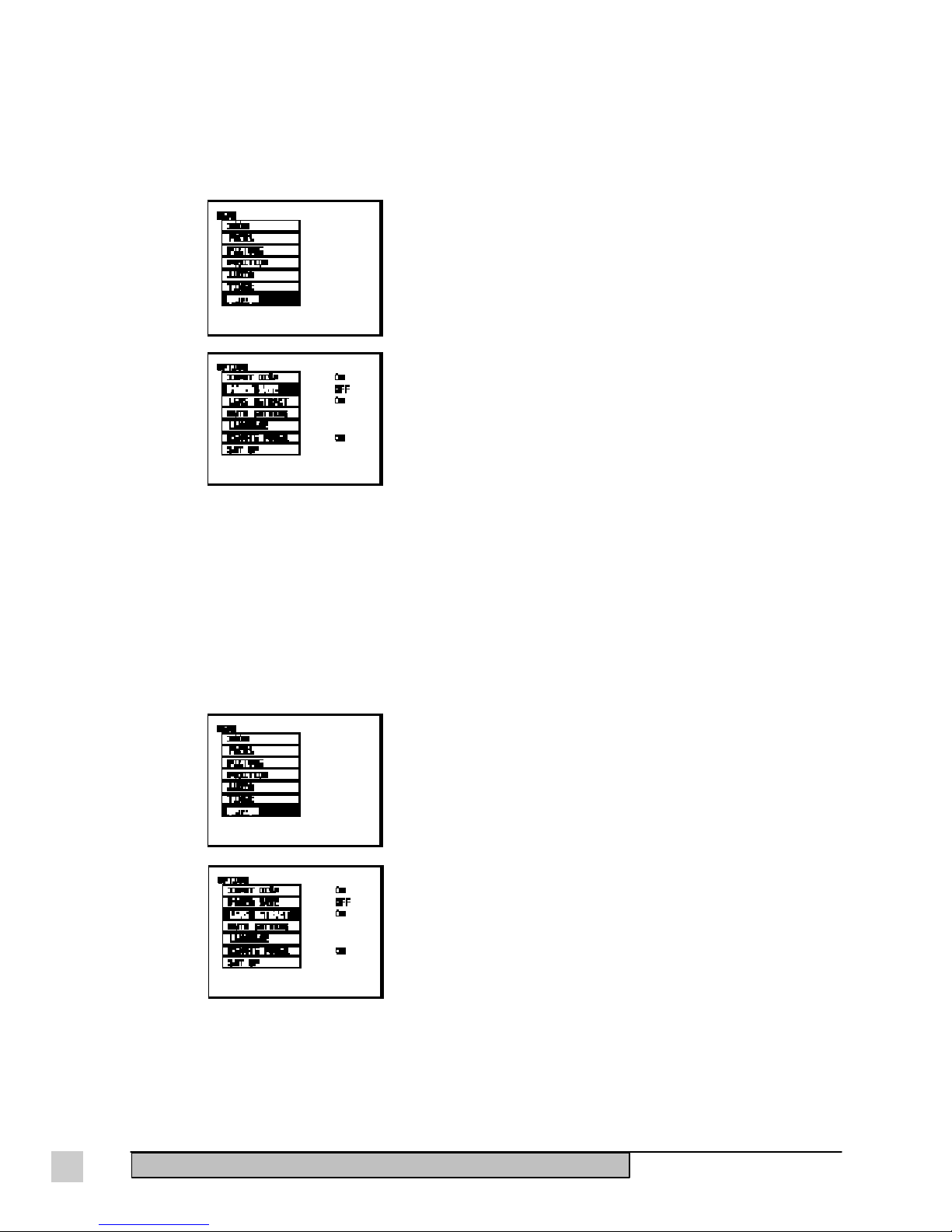
If you want the picture to be muted (temporarily turned off visually)
along with the sound, set the PICTURE MUTE function to ON as
follows:
The procedure below starts from the MUTE SETTING screen.
1 Press the /\ or \/ button to select PICTURE MUTE.
2 Press the < or > button to change the setting to ON.
If the function is set to ON, the picture will be muted along with
the sound when the MUTE button is pressed.
If the function is set to OFF, only the sound will be muted when
the MUTE button is pressed. (Factory setting)
NOTE: Press the MENU button to clear the setting screen and the MENU screen.When PICTURE MUTE is on,
the color projected will be the same color as the BACK COLOR setting.
32 ViewSonic PJ820Operation
Page 42

Other useful on-screen functions
Setting the screen color during picture muting and
when no signal is input
The projector can be set to project a solid blue image or a solid black
image onto the screen if there is no signal from the input connectors
or the signal is not recognized.
This setting is also effective when picture muting is active and when
the countdown timer is running. At the time of shipment from the
factory, the color is set to BLUE.
1 Press the MENU button to display the MENU screen.
2 Press the /\ or \/ button to select OPTION shown on the left.
3 Press the < or > button to display the OPTION screen.
4 Press the /\ or \/ button to select MUTE SETTING.
5 Press the < or > button to display the MUTE SETTING screen.
6 Press the /\ or \/ button to select BACK COLOR.
7 Press the < or > button to change the setting to BLUE or
BLACK. Press the MENU button to clear the setting screen and
the MENU screen.
ViewSonic PJ820
Turning off the on-screen display of input signal
information
To display the currently-selected input signal onto the screen when
the input source is changed
1 Press the MENU button to display the MENU screen.
2 Press the /\ or \/ button to select OPTION.
3 Press the < or > button to display the OPTION screen.
4 Press the /\ or \/ button to select INPUT DISP.
5 Press the < or > button to select OFF.
If this is set to ON when the input source is changed, its name
will be displayed on the screen. (Factory setting) Press the
MENU button to clear the setting screen and the MENU screen.
Operation
33
Page 43
Using the power save function
In order to conserve power, the projector is equipped with a power save function. If no signal is input for ten
minutes or more, the projector automatically switches to Standby Mode. At the time of shipment from the
factory this function is set to OFF.
NOTE: If both this function and the lens retracting function described below are set to ON, the lens will be
automatically retracted when the projector switches to Standby Mode. If this happens, you will need to readjust
the zoom and focus of the lens after starting the projector again.
To activate this function:
1 Press the MENU button to display the MENU screen.
2 Press the /\ or \/ button to select OPTION.
3 Press the < or > button to display the OPTION screen.
4 Press the /\ or \/ button to select POWER SAVE.
5 Press the < or > button to change the setting to ON.
If you change the setting to OFF, the power save function will be
disabled. To clear the setting screen and the MENU screen, press
the MENU button.
Using the lens retracting function
When the projector switches to Standby Mode the projector lens automatically retracts, and extends again
when the projector starts back up. Having this function set to ON is useful if the projector will not be used for
an extended period of time or when the projector is to be transported.
However, once the lens has retracted and the projector has started up again, make sure to readjust the zoom and
focus. At the time of shipment from the factory this function is set to ON.
1 Press the MENU button to display the MENU screen.
2 Press the /\ or \/ button to select OPTION.
3 Press the < or > button to display the OPTION screen.
4 Press the /\ or \/ button to select LENS RETRACT.
5 Press the < or > button to change the setting to ON.
If you set this function to ON, the lens extends and retracts each
time the power is turned on and off.
NOTE: If this function is set to OFF, the lens remains extended at all times. To clear the setting screen and the
MENU screen, press the MENU button.
34 ViewSonic PJ820Operation
Page 44

Disabling the POWER button of the Remote Control Unit
The POWER button on the Remote Control Unit can be disabled to prevent the chance of turning the power off
by mistake when using the Remote Control Unit.
This setting can be made by following the procedure given below.
1 Press the MENU button to display the MENU screen.
2 Press the /\ or \/ button to select OPTION.
3 Press the < or > button to display the OPTION screen.
4 Press the /\ or \/ button to select REMOTE POWER.
5 Press the < or > button to select OFF.
If this is set to ON, the POWER button on the Remote Control
Unit can be used to turn the power on and off. (Factory presetting)
NOTE: Press the MENU button to clear the setting screen and the MENU screen.
Using the countdown timer
The countdown timer can be used at times such as during breaks in meetings by displaying the amount of time
remaining for something on the screen. The countdown time can be set to a maximum of 60 minutes in units of
one minute.
To set the countdown timer:
1 Press the MENU button to display the MENU screen.
2 Press the /\ or \/ button to select TIMER.
3 Press the < or > button to display the TIMER screen.
4 Continue pressing the < or > button to set the time. This
function can be disabled by setting the time to 0.
5 Press the MENU button to clear the menu screen. The countdown
will then start.
NOTE: During the countdown, the screen switches to the color specified by the BACK COLOR setting. If you
would like to turn off the countdown timer, go back to the TIMER screen and set the time to 0 minutes. Press the
MENU button.
ViewSonic PJ820
Operation
35
Page 45

Changing the on-screen display to another language
At the time of shipment, the on-screen displays is set to English. You have the option of changing it to other
languages.
For example, to change the language to German (DEUTSCH), do
the following:
1 Press the MENU button on the remote to display the MENU
screen.
2 Press the /\ or \/ button to select OPTION.
3 Press the < or > button to display the OPTION screen.
4 Press the /\ or \/ button to select LANGUAGE.
5 Press the < or > button to display the LANGUAGE screen.
6 Press the /\ or \/ button to select DEUTSCH. The languages
that can be selected include English (ENGLISH), German
(DEUTSCH), French (FRANCAIS), and Spanish (ESPANOL).
NOTE: Press the MENU button to clear the setting screen and the MENU screen.
36 ViewSonic PJ820Operation
Page 46

TECHNICAL DATA
This chapter consists of the following information:
• Specifications
• Using the serial connector
• Pin configuration and signal names for RGB input connectors
• Accessories
• Parts
• Dimension drawings
Specifications
LCD Type 1.3" Polysilicon (x3) pitch
Pixels 1,440,000 ( 800 x 600 x 3)
Lens Type Retractable Power Focus Lens (1:1.5)
F 2.5 ~ 3.1, f = 48 - 72mm
Display Size 30" - 300"
Projection Distance 39" - 638" (53.1ft.) [1.0m - 16.2m ]
Brightness 750 ANSI Lumens*
Contrast Ratio 200 : 1
Aspect Ratio 4 : 3
Lamp DC Type 280W Metal Halide
Audio Speaker 4cm x 2.85 (elliptical) x 2
Power 2W (1W + 1W) 10%THD
Input Signal Video RGB Analog (75 ohms, 0.7 Vp-p),NTSC /
M-NTSC / PAL / SECAM / S-VIDEO
Sync H/V separated (TTL), Composite NTSC
Frequency f
Compatibility PC IBM® XT, AT, 386, 486, Pentium® or PS/2 and
®
Macintosh
Video NTSC / M-NTSC / PAL / SECAM / S-VIDEO
Resolution Maximum 1024 x 768 @ 85Hz (Compressed)
Connectors RGB 15 pin mini D-sub (x2) [Input]
Video RCA (x1)
S-Video Mini DIN 4-pin (x1)
Audio RCA jack (L/R) for Video, Stereo Mini (x2)
Mouse Round 13-pin (x1)
RS232 D-sub 9-pin (x1)
** Power Mac® (up to 1024 x 768***) Requires Macintosh
: 15.6 - 69kHz fv: 50~85Hz
h
compatibles (VGA up to 1024x768*** non-interlaced)
Compatibility Kit
800 x 600 @ 85 Hz
640 x 480 @ 85Hz
15 pin mini D-sub (x1) [Output]
for RGB,Stereo Mini (x1) for Audio-out
3
* Maximum brightness varies with lamp age and environmental conditions
** Macintosh computers require a ViewSonic Macintosh Kit. Contact ViewSonic (see Chapter 4 Troubleshooting for a Macintosh Kit).
*** 1024 x 768 (advanced video compression)
ViewSonic PJ820
Continued....
Technical Data
37
Page 47

Specifications (continued)
Power Voltage AC 100-120 / 220 - 240 VAC
50 / 60 Hz (Automatic)
Consumption 390 Watts
User Controls/ Physical Power, Menu, Arrows, Focus, Zoom, Input,
Functions Lens Shift, Adjustable Legs
On-Screen Power, Focus, Brightness, Contrast, W-Balance
(R,G,B), Color,Tint, Sharpness, Volume, Balance,
Horizontal Blank-Right, Horizontal Blank-Left,
Horizontal Position, Zoom, Vertical Position, Vertical
Size, Vertical Blank-Top, Vertical Blank-Bottom,
Display, Power Save, (Audio) Mute, Language,
Remote Power, Timer, Lens Retract, Picture Mute,
Background Color
Video Pixel Clock 89 MHz
Operating Temperature 32°F to 104°F (0°C to 40°C)
Conditions Humidity 20 to 80% (no condensation)
Storage Temperature -4°F to +140°F (-20°C to +60°C)
Conditions Humidity 5% to 80% (no condensation)
Dimensions Physical 421mm (W) x 163mm (H) x 300mm (D)
16.6" (W) x 6.4" (H) x 11.8" (D)
Packing 530mm (W) x 420mm (H) x 330mm (D)
20.9" (W) x 16.5" (H) x 13.0" (D)
Weight Net 9.8kg (21.6lb)
Gross 12.5kg (27.5lb)
Regulatory UL1950, C-UL, FCC-A, EN60950, CE
Agencies
MTBF 10,000 hours excluding lamp
Lamp Life 3000 hrs. (maximum)
Power savings “On” Green 390 W
“Stand By” Amber < 8 W
Other Features Compatible with the display data channel standards
DDC1
and DDC2B. 16.7 million colors, Powered
Zoom Lens, 4 Languages, Exclusive Polarization
Converter, Exclusive Compression Technology, IR
Remote (PS/2 Serial Mouse compatible), Front/Rear
Projection Compatibility.
All products and trademarks are brand names of their respective companies. Specifications are subject
to change without notice.
38 ViewSonic PJ820
Technical Data
Page 48

Timing Chart
The ViewSonic PJ820 Office Theater
TM
projector can run at an
extensive range of resolutions and refresh rates. Certain standard
resolutions are factory preset. There are also six timings which are
User Definable Timings
user definable. For example, if your video card is set up to run 1024
pixels x 768 lines at a 75 Hz refresh rate, once you have adjusted
Resolution Maximum
Refresh Rate
pixels x lines Hz
640 x 480 75
800 x 600 75
1024 x 768 75 compressed
All resolutions are non-interlaced.
the projector size and position to your preferences, the PJ820 saves
this information to memory. Every time you run this resolution at
this refresh rate, the projector recalls your adjustments.
The following table lists the maximum refresh rates that the
ViewSonic PJ820 will operate at a number of standard resolutions.
While the PJ820 is capable of this level of performance, not all
video cards are capable of running at these refresh rates. See your
video card user's guide to ensure compatibility.
Display mode name
AUTO Automatically switches to whichever of the following signal modes best matches the input signal.
VGA 400 640 x 400 31.5 70.0
VGA 480 640 x 480 31.5 60.0
MAC 13 640 x 480 35.0 66.7
TM
PC-98
VESA 640 x 480 37.9 72.8
S-VGA 1 800 x 600 35.2 56.3
S-VGA 2 800 x 600 37.9 60.4
S-VGA 800 x 600 46.9 75.0
S-VGA 4 800 x 600 48.1 72.0
S-VGA 5 800 x 600 32.1 51.0
MAC 16 832 x 624 49.7 74.6
XGA 1 1024 x 768 48.4 60.0
XGA 2 1024 x 768 56.4 70.0
XGA 3 1024 x 768 68.7 85.0
MAC 19 1024 x 768 60.2 75.0
No. of dots Horizontal scanning frequency (kHz) Vertical scanning frequency (Hz)
640 x 400 24.8 56.4
Signal data
NOTE: The display resolution for the ViewSonic PJ820 projector is 800 x 600 dots. If any of the above
signals which have resolutions greater than this are input, the resolution will be converted to 800 x 600 dots
using the advanced compress technology. The setting screen and the MENU screen can both be cleared by
pressing the MENU button.
ViewSonic PJ820
Technical Data
39
Page 49

Using the serial connector
The serial connector on the connector panel on the side of the projector conforms to the RS-232C interface specification so
the projector can be controlled by a personal computer. Be sure to use a proper communication cable to connect the
projector with your personal computer.
Computer
Connector panel on side of projector
D-SUB 9-pin
Communication cable
Pin layout and signal names for serial connector
Pin No. Signal Name Contents
(1) NC
5
9
1
6
Projector
D-SUB 9-pin connector (male)
seen from the outside
(2) RXD Received data
(3) TXD Transmitted data
(4) NC
(5) GND GND
(6) NC
(7) RTS Connected internally
(8) CTS Connected internally
(9) NC
Communication Settings
Signal level Determined by the RS-232C interface
Synchronizing method Asynchronous
Baud rate 9600 bps
Parity None
Character length 8 bits
Stop bit 1 bit
40 ViewSonic PJ820
Technical Data
x parameter None
S parameter None
Page 50

Using the serial connector (continued)
Basic format
Each packet which is sent from the computer starts with STX. Following this is the command itself and the parameters for
that command (if any), and the packet then ends with ETX. Add parameters when necessary according to the control
contents.
NOTE: If sending multiple commands, check that a response has been received from the projector for one command
before sending the next command. If an incorrect command is sent from the personal computer, the “ER401” command
will be sent from the projector to the personal computer.
Control Commands
Cable Specifications
Command Control Contents Remarks
PON Power ON In standby mode, all
commands other than the
POF Power OFF PON command are ignored
Parameter
AVL Volume 000 = Adjustment value 0
AMT Mute 0 = MUTE OFF
IIS Input signal VID = VIDEO
At the projector
1
2
3
NC
:
063 = Adjustment value 63
Parameter
1 = MUTE ON
Parameter
RG1 = RGB1
RG2 = RGB2
At the computer
(DTE specifications)
NC
1
2
3
ViewSonic PJ820
4
5
6
7
8
9
NC
NC
NC
NC
NC
NC
4
5
6
7
8
9
Technical Data
41
Page 51

Pin configuration and signal names for RGB input connectors
NOTE: Pin No. 12 and pin No. 15 on
15-pin connectors will only work if the
computer supports them.
Accessories
Pin No.
1
2
3
9
12
13
14
15
4–8, 10, and 11
Signal name
R
G/G•SYNC
B
NC
SDA
HD/SYNC
VD
SCL
GND
Contact ViewSonic (see Chapter 4 Troubleshooting for contact
details) for the following accessories:
Parts
• Ceiling Mount Kit Name: CMK800
• Macintosh Kit Name: PJMAC1
• Replacement Lamp: RLU820
Contact ViewSonic (see Chapter 4 Troubleshooting) for an Air Filter
Kit.
42 ViewSonic PJ820
Technical Data
Page 52

Dimensions
Front View
Width 421mm (16.6")
Height 163mm (6.4")
Top View
Side View
Depth 300mm (11.8")
ViewSonic PJ820
Technical Data
43
Page 53

44 ViewSonic PJ820
Technical Data
Page 54

TROUBLESHOOTING
4
If your ViewSonic® PJ820 Projector is not performing properly, use this troubleshooting chart for quick
solutions to common problems. If the problem persists, call your dealer. For further support contact ViewSonic
Customer Support in your area:
U.S. and Canada only: 1-800-688-6688
From outside U.S. and Canada: 909-869-7976
From Europe: 44 (1293) 643-900
From Asian/Pacific Rim countries: 886 (2) 248-4072
Internet E-Mail: vstech@viewsonic.com
World Wide Web: http://www.viewsonic.com
Before asking for service, check the following:
Problem Possible Cause
Power does not turn on • The power cord is not connected.
• The main power switch on the projector is turned off.
• Power is not being supplied to the wall outlet.
• TEMP indicator is illuminated or flashing.
• LAMP indicator is illuminated or flashing.
• The lamp unit cover has not been correctly installed.
• The REMOTE POWER function has been set to “OFF”.
No picture appears • The lens cap may still be attached to the lens.
• The video signal input source may not be connected properly.
• The input selection setting may not be correct.
• The BRIGHT adjustment setting may be at the minimum possible setting.
• The PICTURE MUTE function has been set to “ON”.
The picture is fuzzy • The projector may not be focused correctly, or the projector may not
be positioned the correct distance from screen.
• The lens may be dirty.
• The projector may not be set up so that it is perpendicular to the screen.
COLOR is too light • COLOR or TINT setting may be incorrect.
TINT is poor
No sound can be heard • The audio signal source may not be connected properly.
Remote control unit does • The batteries may be spent, or they may be inserted incorrectly.
not operate
The picture does not • The correct input signal may not be selected.
display correctly
• The input source connected to the projector many not be set correctly.
• The volume adjustment may be at the lowest possible setting.
• The MUTE function may be active.
• There may be an object between the remote control unit and the
projector which is blocking the infrared signals.
• The remote control unit may be out of the operation range.
• The input signal setting mode (TV-SYSTEM/SIGNAL MODE) may not be
set correctly.
• There may be a problem with the VCR tape or other signal source.
®
ViewSonic PJ820
Troubleshooting
45
Page 55

Indicators
There are two indicators on the front of the projector which give information about the operating condition of
the projector. These indicators illuminate or flash to warn you about problems that have occurred inside the
projector so you can turn off the power and check the table below for the cause.
Indicator name
TEMP indicator
TEMP
LAMP indicator
Indicator display
Illuminated (red)
Flashing (red)
TEMP indicator
Problem
The internal projector
temperature is too high.
The metal halide lamp
has turned off
automatically because
the internal temperature
has risen to an
abnormally high level.
Possible cause
The ventilation holes
may be covered.
The ambient
temperature in the
place of use may be
too high.
The air filter may be
blocked.
Remedy
Uncover the ventilation holes.
Set up the projector in a place
where the temperature is
between 32
104
humidity is between 40% and
75% (with no condensation).
Turn off the main power
supply by, and then clean the
air filter.
0
0
F (00C) and
F (400C) and the
LAMP indicator
Lamp
It is nearly time to
replace the lamp unit.
Illuminated (red)
The metal halide lamp
switches off
automatically.
Flashing (red)
Does “LAMP” appear
on the screen after the
projector is turned on?
The power may have
been turned on
immediately after it was
turned off.
There may be an
abnormality in the lamp
circuit.
This occurs when the
operation time for the lamp
unit is nearing 2,800 hours.
Contact ViewSonic
Customer Support or an
Authorized Service Center.
Wait for a while until the lamp
unit cools down before
turning the power back on
again.
Turn off the main power
supply and then contact an
Authorized Service Center.
IMPORTANT:
Before carrying out any of the procedures in the “Remedy” column above, be sure to turn off the main
power. If the main power turns off after the TEMP indicator starts flashing, STOP and call ViewSonic
Customer Support or an Authorized Service Center for further instructions. (See Chapter 4
Troubleshooting for contact numbers.)
46 ViewSonic PJ820
Troubleshooting
Page 56

CARE AND SAFETY TIPS
CAUTION
●
If smoke, abnormal noise, or strange odor is present, immediately switch the projector
off and call your dealer or ViewSonic
Doing so in this condition could result in fire and/or electric shock.
●
Never unscrew and remove the top cover of the projector. However, to remove the small
cover over the cable connections, see Chapter 1 on Getting Started. The projector
contains high-voltage parts. You may receive an electric shock if you touch these parts.
For assistance call your dealer or ViewSonic® Customer Support.
Safety Precautions and Helpful Tips
Setting-up the projector
●
Place the projector in a well-ventilated area so heat from the projector will adequately dissipate.
●
Do not place anything on top of the projector.
●
Place the projector on a flat surface strong enough to support the projector's weight. Failing to do so
could result in severe injury and/or damage to the projector.
®.
It is dangerous to continue using the projector.
5
●
Do not set up the projector directly on top of a plastic sheet or carpet. Plastic sheets can stick to the air
filter, which can cause the inside of the projector to overheat and the power supply to switch off.
●
Do not cover the air filter or the air outlet, and do not put foreign objects into the projector. Doing so
may cause the projector to overheat, which can cause fire, electric shock, and/ or damage to the
projector.
●
Avoid setting up the projector in places which are subject to vibration or shocks. Strong motor vibration
.
will damage internal parts and may result in malfunctions or injury.
●
Avoid seting up the projector near high-voltage power lines or motors, which can cause electromagnetic
interference.
●
If mounting the projector, ask a qualified technician do it. Improper installation can result in injury and/
or electric shock. To mount the projector on the ceiling, contact ViewSonic
Ceiling Mounting Kit, Model No. CMK800.
®
Customer Support to order a
Power cord safety tips
●
Do not handle the power cord plug with wet hands. Doing so may cause electric shock.
●
Plug the power cord securely into the wall socket. Failing to do so may generate enough heat to cause a
fire. If the plug is damaged or the wall socket plate is loose, do not use them.
●
Do not do anything that might damage the power cable, such as twisting or pulling it excessively,
placing heavy objects on top of it, placing it near any source of heat, or by making modifications to it. If
the power cable becomes damaged, have it repaired at an Authorized Service Center.
●
Be sure to unplug all cables before moving the projector.
●
When unplugging the power cable, hold the plug, not the cable.
ViewSonic PJ820
Care and Safety Tips
47
Page 57

Using the projector safely
●
Do not look into the lens while the projector is being used. The strong light emitted from the projector’s
lens can damage your eyes.
●
Do not put your hands, face or any objects close to the air outlet port. Doing so can result in burns and/or
damage to objects.
●
Avoid exposing the projector to direct sunlight or other heat source.
●
Ensure the area around the projector is clean free of moisture, dust and oil fumes. Failing to do so can result
in fire or electric shock.
●
Do not put objects on top of the projector. If an object gets inside the projector, call ViewSonic® Customer
Support or an Authorized Service Center.
●
Do not remove the cover or modify it in any way. High voltages inside the projector can cause severe
electric shock. For any inspection, adjustment or repair work, contact ViewSonic
®
Customer Support or an
Authorized Service Center.
●
Always handle the projector with care when moving it.
To get the best picture quality
●
Do not touch the surface of the lens with your bare hands. Dirt from fingerprints or anything else will be
magnified and projected onto the screen.
●
When not using the projector, retract the lens and cover it with the lens cap. This prevents scratches on the
lens which will lessen picture quality.
●
To ensure that the projected picture has good contrast, draw curtains or blinds over any windows, turn off
any fluorescent lights near the screen, and cover floor or walls that have highly-reflective surfaces.
About condensation
●
Condensation is formation of water droplets on surfaces, such as on the cold windows that are warmed
suddenly in winter. Condensation that occurs on the surfaces of lenses or the the mirror inside the projector
may cause the picture to appear out of focus or may not be visible.
●
Excessive condensation causes the projector to stop functioning. Common causes of condensation are high
humidity or the result of moving the projector suddenly from a cold environment into a warm one. In such
cases, the projector normally resumes functioning as it becomes conditioned to the temperature of the new
environment.
48 ViewSonic PJ820
Care and Safety Tips
Page 58

Cleaning and Maintenance
Be sure to unplug the power cord from the wall outlet before doing any cleaning or maintenance.
Cleaning the projector
●
To clean the projector housing, wipe it with a soft, dry cloth. If the housing is particularly dirty, wet the
cloth in water mixed with a small amount of non-abrasive cleaner, squeeze the cloth thoroughly, and then
wipe the projector housing. Then wipe the housing dry with a dry cloth.
●
To clean the lens use a photography lens blower/brush or a chamois cloth to wipe off any dust or lint.
Do not wipe the lenses with a cloth that produces lint or is covered with dust
●
Wipe the power cable regularly with a dry cloth to prevent it from becoming covered with dust.
.
Accumulated dust attracts humidity which could result in fire.
●
Ask an Authorized Service Center to clean inside the projector at least once a year. If dust is left to build up
inside the projector without being cleaned out, fire or problems with operation can occur.
Cleaning the air filter
If the air filter becomes clogged, the internal temperature of the projector will rise. Then the TEMP indicator
will flash and the projector will switch automatically to Standby Mode. If this occurs do the following:
1 Turn off the main power supply and unplug the power cord from the wall outlet. Turn off the main power
supply before unplugging the cord from the wall outlet.
2 Gently turn the projector upside down.
3 Remove the air filter cover. Hold the indents on the air filter cover with your hands and pull the air filter
unit out of the projector.
Indent
Air filter unit
4 Remove the air filter clamp and then take out the air filter. Insert your finger into the indent in the air filter
cover, bend the air filter clamp slightly inward, and then lift the air filter clamp upward to remove it.
ViewSonic PJ820
Indent
Air filter
Air filter cover
Air filter
clamp
Continued...
Care and Safety Tips
49
Page 59

Cleaning the air filter (continued)
5 Clean the air filter and the air filter clamps. Use a vacuum cleaner to clean off any accumulated dust.
Air filter clamps
Air filter
6 Install the air filter and the air filter clamp onto the air filter cover. Place the air filter inside the air filter
cover, and then return the air filter clamps to their original position as shown below.
7 Replace the air filter cover. Slide the air filter cover into the projector until the clamps on the air filter
cover are aligned with the clamp holes in the projector.
NOTE
Be sure to install the air filter cover before using the projector. If the projector is used without the air
filter, dust and other foreign particles will be drawn into the projector, resulting in malfunctions.
If the dust cannot be removed by cleaning, it is time to replace the air filter. Contact ViewSonic
Customer Support and order a replacement air filter.
®
50 ViewSonic PJ820
Care and Safety Tips
Page 60

Replacing the lamp unit
CAUTION
●
Never touch the lamp inside the lamp unit at any time. Oils on the skin can make the lamp unsafe and
reduce its life expectancy.
●
After turning off the MAIN POWER switch and disconnecting the power cord from the wall socket,
let the lamp unit cool down before removing it. Failure to do so could result in severe burns. Wait for
the lamp to cool down before replacing the lamp unit.
●
Handle the lamp unit very carefully. The metal halide lamp inside the lamp unit contains gas under
high pressure. If it is dropped or hits other objects it may break, which could cause injury or problems
with operation. Ask an authorized waste disposal agency to dispose of the old lamp unit.
Lamp unit replacement period
The lamp used as the light source must be replaced after approximately 2,800 hours of use. If the lamp is not
replaced after the cumulative usage time has passed 3,000 hours, the projector will automatically switch to
Standby Mode after approximately ten minutes of operation. Make sure you complete Steps 7 to 11 starting on
the next page within ten minutes (before Standby Mode is initiated).
Screen display after 2,800 hours (cumulative)
If you continue to use the lamp unit after 2,800 hours of total usage , the on-screen display shown below will
appear as a reminder each time the projector is turned on. This display will continue to appear until you press
any button.
Replacing the lamp unit
In order to replace the halide lamp, the entire lamp unit must be replaced. To do this contact ViewSonic
Customer Support and order Lamp Replacement Unit (See Chapter 4 Troubleshooting for contact details).
1 Disconnect the power cord plug from the wall outlet and check that the area around the lamp unit has cooled
down.
2 Use a Phillips screwdriver to remove the screw which is securing the lamp unit cover on the right side of the
projector and then remove the lamp unit cover.
Read the CAUTION on the lamp unit cover before continuing.
Fixing screw for the lamp
unit cover
Lamp unit cover
ViewSonic PJ820
Care and Safety Tips
®
Continued...
51
Page 61

Replacing the lamp unit (continued)
3 Turn the fixing screw for the lamp unit by hand until it turns freely.
CAUTION:
The lamp unit will be hot after the projector has been recently used. To prevent being burned, do not let it
touch your skin directly.
Fixing screw for the lamp unit
4 Hold the handle which is attached to the lamp unit and gently pull the lamp unit out from the projector.
Handles
5 Insert the new lamp unit making sure it is positioned correctly (the fixing screw is on the bottom). Then turn
the fixing screw on the lamp unit by hand until it is securely tightened.
6 Securely install the lamp unit cover, and then use a Phillips screwdriver to securely tighten the fixing screw
for the lamp unit cover.
NOTE
Be sure to install the lamp unit and the lamp unit cover securely. If they are not securely installed, the
protection circuit may be activated, which prevents the projector from being turned on.
7 Insert the power cord plug into the wall outlet and then press the MAIN POWER switch on the front of the
projector to turn on the power.
NOTE:
If the power does not turn on when the MAIN POWER switch is pressed, turn the MAIN POWER switch off
again and check that the lamp unit and the lamp unit cover are securely installed. Then turn the MAIN
POWER switch back on.
8 Press the POWER button on the projector or remote control unit so a picture appears on the screen.
52 ViewSonic PJ820
Care and Safety Tips
Continued...
Page 62
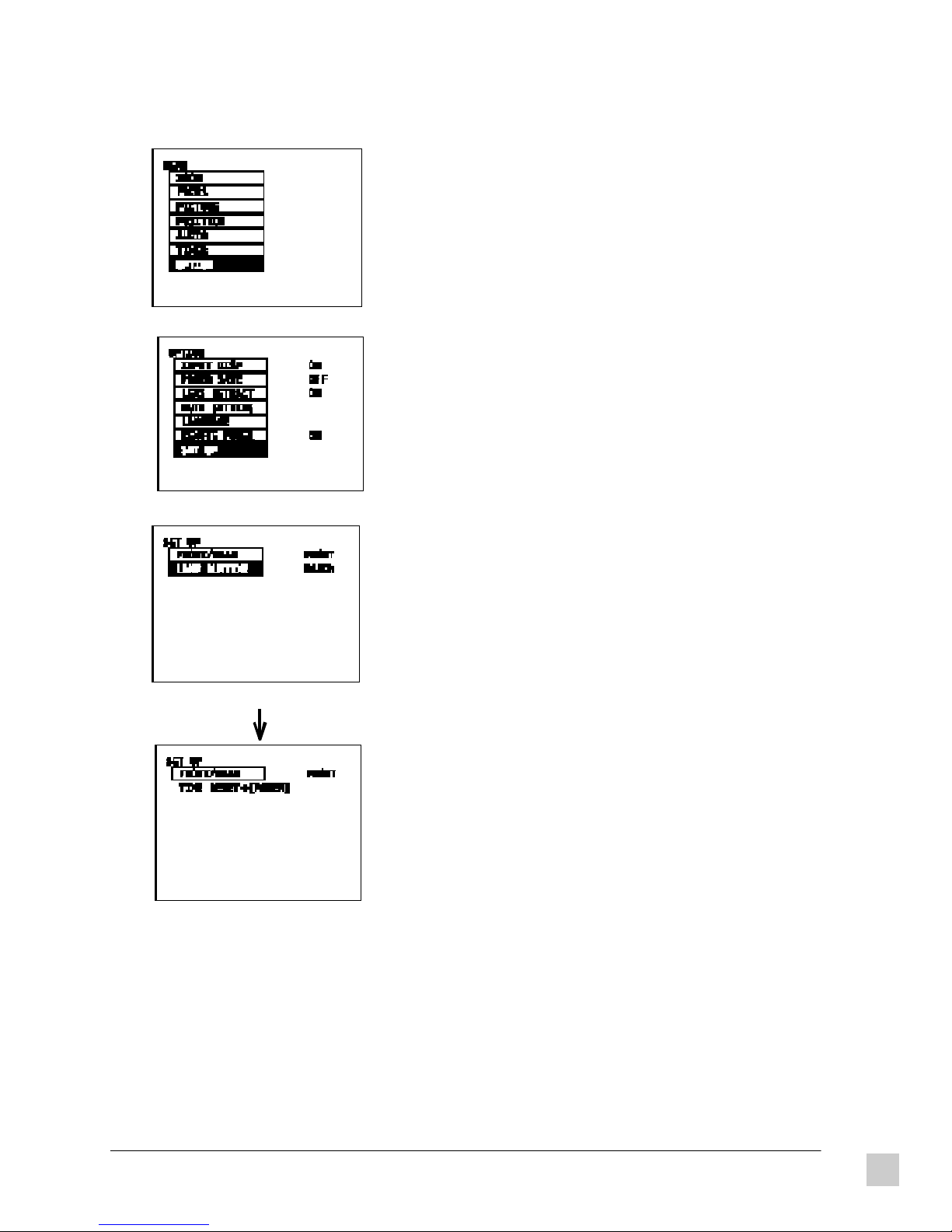
Replacing the lamp unit (continued)
9 Press the MENU button to display the MENU screen.
Press the /\ and \/ buttons to select OPTION.
10 Press the < and > buttons to display the OPTION screen.
Press the /\ and \/ buttons to select SET UP.
11 Press the < and > buttons to display the SET UP screen.
Press the /\ and \/ buttons to select LAMP RUNTIME.
The cumulative usage time of the current lamp unit will be
displayed on the screen.
Press the < or > button on the projector control panel
continuously for three seconds or more.
The < and > buttons on the remote control unit cannot be
used at this time.
Turn off the power while the SET UP screen is being displayed
(the screen showing TIME RESET). This will reset the
cumulative usage time for the lamp unit.
ViewSonic PJ820
If any other buttons are pressed while TIME RESET is
displayed, the display will return to LAMP RUNTIME and the
button pressed will take effect.
Care and Safety Tips
53
Page 63

LIMITED WARRANTY
VIEWSONIC PJ820 PROJECTOR
What the warranty covers:
ViewSonic
period. If a product proves to be defective in material or workmanship during the warranty period,
ViewSonic will at its sole option repair or replace the product with a like product. Replacement product or
parts may include remanufactured or refurbished parts or components.
How long the warranty is effective:
The ViewSonic PJ820 projector is warranted for three (3) years for all parts excluding the lamp, three (3)
years for all labor, and ninety (90) days for the lamp from the date of the first consumer purchase.
Who the warranty protects:
This warranty is valid only for the first consumer purchaser.
What the warranty does not cover:
1. Any product on which the serial number has been defaced, modified or removed.
2. Damage, deterioration or malfunction resulting from:
a. Accident, misuse, neglect, fire, water, lightning, or other acts of nature, unauthorized product
b. Repair or attempted repair by anyone not authorized by ViewSonic.
c. Any damage of the product due to shipment.
d. Removal or installation of the product.
e. Causes external to the product, such as electric power fluctuations or failure.
f. Use of supplies or parts not meeting ViewSonic’s specifications.
g. Normal wear and tear.
h. Any other cause which does not relate to a product defect.
3. Removal, installation, and set-up service charges.
How to get service:
1. For information on obtaining warranty service, call ViewSonic. The customer support telephone numbers
are: U.S. and Canada 1-800-688-6688; from outside the U.S. and Canada 909-869-7976; from Europe
+44(1293)-643-900; from Asian /Pacific Rim countries 886 (2) 248-4072. Internet E-Mail
address:vstech@viewsonic.com or World Wide Web:http://www.viewsonic.com
2. To obtain warranty service, you will be required to provide (a) the original dated sales slip, (b) your
name, (c) your address, (d) a description of the problem, and (e) the serial number of the product.
3. Take or ship the product prepaid in the original container to your ViewSonic dealer, any ViewSonic
service center or ViewSonic.
4. For additional information or the name of the nearest ViewSonic service center, contact your ViewSonic
dealer or ViewSonic.
Limitation of implied warranties:
THERE ARE NO WARRANTIES, EXPRESS OR IMPLIED, WHICH EXTEND BEYOND THE
DESCRIPTION CONTAINED HEREIN INCLUDING THE IMPLIED WARRANTY OF MERCHANTABILITY
AND FITNESS FOR A PARTICULAR PURPOSE.
Exclusion of damages:
VIEWSONIC’S LIABILITY IS LIMITED TO THE COST OF REPAIR OR REPLACEMENT OF THE
PRODUCT. VIEWSONIC SHALL NOT BE LIABLE FOR:
1. DAMAGE TO OTHER PROPERTY CAUSED BY ANY DEFECTS IN THE PRODUCT, DAMAGES
BASED UPON INCONVENIENCE, LOSS OF USE OF THE PRODUCT, LOSS OF TIME, LOSS OF
PROFITS, LOSS OF BUSINESS OPPORTUNITY, LOSS OF GOODWILL, INTERFERENCE WITH
BUSINESS RELATIONSHIPS, OR OTHER COMMERCIAL LOSS, EVEN IF ADVISED OF THE
POSSIBILITY OF SUCH DAMAGES.
2. ANY OTHER DAMAGES, WHETHER INCIDENTAL, CONSEQUENTIAL OR OTHERWISE.
3. ANY CLAIM AGAINST THE CUSTOMER BY ANY OTHER PARTY.
Effect of state law:
This warranty gives you specific legal rights, and you may also have other rights which vary from state to
state. Some states do not allow limitations on implied warranties and/or do not allow the exclusion of
incidental or consequential damages, so the above limitations and exclusions may not apply to you.
Sales outside the U.S.A.:
For ViewSonic products sold outside of the U.S.A., contact your ViewSonic dealer for warranty information
and service.
®
warrants its products to be free from defects in material and workmanship during the warranty
modification, or failure to follow instructions supplied with the product.
REV 3/13/97
54 ViewSonic PJ820
Care and Safety Tips
Page 64

Index
Symbols
13-pin
9
A
Accessories
Adjustable legs 4,
Adjuster button 4,
Advanced video compression
Air filter
Another language
Audio 31,
Audio In 10,
Audio Out
Audio-visual equipment
42
5
5
49
36
37
19
10
8
B
Back color
Batteries 1,
Battery compartment cover
Beaded screen
Blanking
Blue component
Bottom blanking
Brightness 2,
35
11
16
6
28
26
28
25
C
Cable specifications
Care
47
Caution
CD-ROM
CE certification
Ceiling mount
Ceiling mounting kit
Cleaning
Click button 1
Click button 2
Clock adjustment
Clock frequency
Clock phase
Color
Color subcarrier frequency
Communication settings
Compatibility
Computer connections
Condensation
Connectors
Contrast
Contrast ratio
v
1
49
30
25
37
37
25
41
iv
7
47
17
17
30
30
20
40
9
48
2
Control commands
Countdown timer
Cropped
Customer support 45,
28
41
35
54
D
D-SUB 15-pin
2
Deutsch
Dimensions 38,
Display
9
36
43
37
E
English
Español
36
36
F
Factory settings
FCC information
Flexible translucent screen
Focus 15,
Français
French
Front mounting
Front reflective screens
Fuse holder
36
36
21
iv
6
23
24
6
15
G
German
Green component
36
26
H
Helpful tips
Horizontal positions
Horizontal scanning frequency
Horizontal size/width
47
27
20
29
I
Important safety notice
Indicators
Input signal
Input source
46
37
19
v
L
Lamp
LAMP indicator 15,
Lamp life
Lamp unit
Lamp unit cover
46
46
38
51
4
ViewSonic PJ820
Index
55
Page 65

LCD 2,
Left-side blanking
Lens 23,37,
Lens retracting function
Lens shift
Lens shift dial
37
28
49
15
22
M
Macintosh® mouse port
Main power switch 12,
Maintenance
Menu button 15,
Model name
Model number
Mouse
MTBF
Mute button 16,
Muting
Muting the sound
49
16
ii
ii
10
38
32
2
31
N
NTSC 20,
25
34
15
17
Power savings
Power supply cord
Problems
Projection method
PS/2 mouse port
38
iv
45
24
17
R
Rear mounting
Rear translucent screens
Red component
Refresh rate
Regulatory agencies
Remote control 2,18,
Remote control signal receptor 4,
Remote control unit 11,16,17,31,
Reset
Resolution 37,
RGB 1
RGB 2 10,
RGB signal input 21,
Right-side blanking
Rigid-type translucent screen
21
19
24
6
26
39
38
45
39
19
26
28
6
15
35
O
On-screen display of input signal information
Operating Conditions
Operation
15
38
P
Packing material
PAL 20,
Parts
PC Serial mouse port
Picture
Picture position
Picture quality
Picture setting
Pin configuration
Pin layout
Plug & Play
Pointer button 16,
Polarized screen
Position screen
Power
Power button 12,15,16,
Power cord safety tips
Power indicator
Power Off
Power On
Power on and off
Power save function
25
42
45
38
1
17
27
48
25
42
40
2
17
6
30
35
47
12
12
12
13
34
33
S
S-Video In 10,
S-Video input signals
S-Video/Video In
Safety precautions
Safety tips
Screen color during picture muting and when no
signal is input
Screen requirements
SECAM 20,
Serial
Serial connector
Serial number
Serial port
Setting up the projector 5,
Setup dimensions
Setup positions
Sharpness
Side connector panel
Signal data
Signal mode
Signal names 40,
Signal receptor
Silver screen
Sound
Sound and picture
Spanish
Speakers
10
45
19
20
19
47
47
33
6
25
40
ii
9
47
7
7
25
10
39
21
42
18
6
32
36
15
56
Index
ViewSonic PJ820
Page 66

Standard (STD) button
Storage conditions
System configuration
38
T
16
8
Table mount
Technical data
TEMP
TEMP indicator 15,
Timer screen
Timing chart
Tint
25
Top blanking
Troubleshooting
7
37
46
46
35
39
28
45
U
User Controls/Functions
User definable timings
38
39
V
Vertical position
Vertical positions
Vertical scanning frequency
Video
Video In 10,
Volume 31,
Volume adjustment
38
22
27
19
32
16
W
20
Warning
Warranty
Weight
White balance
White screen
Wireless mouse/pointer
Wireless pointer
v
54
38
26
6
2
Z
Zoom
ViewSonic PJ820
23
17
Index
57
Page 67

For Customer Support contact ViewSonic® at:
U.S. and Canada only
1-800-688-6688
From outside U.S. and Canada
909-869-7976
From Europe
44 (1293) 643-900
From Asian/Pacific Rim countries
886 (2) 248-4072
Internet E-Mail:
vstech@viewsonic.com
World Wide Web:
http://www.viewsonic.com
V801068201
ViewSonic® Corporation
381 Brea Canyon Road
Walnut, CA 91789
Tel (909) 869-7976
Tel (800) 688-6688
Fax (909) 468-1202
 Loading...