

ViewSonic N4200w-1 VS10945-1M, N4200w-1M VS10945-1M, N4200w-1M, VS10945-1M Service Manual
Service Manual
ViewSonic N4200w-1(M)
Model No. VS10945-1M
42” LCD TV
(N4200w-1M_SM_Rev.1a_Apr.2006)
ViewSonic® 381 Brea Canyon Road, Walnut, California 91789 USA - (800) 888-8583
Copyright © 2006 by ViewSonic Corporation. All rights reserved. No part of this publication may be
reproduced, transmitted, transcribed, stored in a retrieval system, or translated into any language or
computer language, in any form or by any means, electronic, mechanical, magnetic, optical, chemical,
manual or otherwise, without the prior written permission of ViewSonic Corporation.
Disclaimer
ViewSonic makes no representations or warranties, either expressed or implied, with respect to the contents
hereof and specifically disclaims any warranty of merchantability or fitness for any particular purpose. Further,
ViewSonic reserves the right to revise this publication and to make changes from time to time in the contents
hereof without obligation of ViewSonic to notify any person of such revision or changes.
Trademarks
Optiquest is a registered trademark of ViewSonic Corporation.
ViewSonic is a registered trademark of ViewSonic Corporation.
All other trademarks used within this document are the property of their respective owners.
Revision History
Revision SM Editing Date ECR Number Description of Changes Editor
1a 04/11/06 Initial Release Sophia Kao
ViewSonic Corporation Confidential - Do Not Copy N4200w-1
1

ViewSonic Corporation Confidential - Do Not Copy N4200w-1
2
TABLE OF CONTENTS
1. Precautions and Safety Notices ……………………………………………. 3
2. Service tool & equipment required……………………………………………6
3. Specification ………………………………………………………………….. 6
4. Front Panel Function Control Description …………………………………. 10
5. Adjustment Procedure………………………………………………………… 13
6. Exploded Diagram and Exploded Parts List ………………………………. 45
8. Schematic Diagrams ………………………………………………………… 49
9. Wiring Diagram………………………………………………………………….63
10. PCB Layout Diagrams ……………………………………………………….. 64
11. Trouble Shooting Flow Chart…………………………………………………. 73
12. Recommended Spare Parts List ……………………………………………..78
7. Block Diagrams……………………………………………………………….. 47
1. Precaution and Safety Notices
1.1 Safety Precautions
This LCD TV is manufactured and tested on a ground principle that a user’s safety comes first.
However, improper or installation may cause damage to the LCD TV as well as to the user. Carefully go
over the following WARNINGS before installing and keep this guide handy.
WARNINGS:
Read these instructions completely before using the equipment.
Keep these instructions in a safe place.
1. Heed all warnings.
2. Follow all instructions.
3. Do not use this equipment near water.
4. Clean with a soft, dry cloth. If further cleaning is required, see “Cleaning the Display” in this guide for
further instructions.
5. Do not block any ventilation openings. Install the equipment in accordance with the manufacturer’s
instructions.
6. Do not install near any heat sources such as radiators, heat registers, stoves, or other devices (including
amplifiers) that produce heat.
7. Do not attempt to circumvent the safety provisions of the polarized or grounding-type plug. A
polarized plug has two blades with one wider than the other. A grounding type plug has two blades and
a third grounding prong. The wide blade and the third prong are provided for your safety. If the plug
does not fit into your outlet, consult an electrician for replacement of the outlet.
8. Protect the power cord from being tread upon or pinched, particularly at the plug, and the point where
if emerges from the equipment. Be sure that the power outlet is located near the equipment so that it is
easily accessible.
9. Only use attachments/accessories specified by the manufacturer.
10. Use only with the cart, stand, tripod, bracket, or table specified by the manufacturer,
or sold with the equipment. When a cart is used, use caution when moving the cart/
equipment combination to avoid injury from tipping over.
11. Unplug this equipment when it will be unused for long periods of time.
Refer all servicing to qualified service personnel. Service is required when the unit has been damaged in
any way, such as: if the power-supply cord or plug is damaged, if liquid is spilled onto or objects fall into
the unit, if the unit is exposed to rain or moisture, or if the unit does not operate normally or has been
dropped.
1.2 Product Safety Notice
Electrical and Mechanical parts in this chassis have special safety visual inspections and the protection
afforded by them can not necessarily be obtained by using replacement components rated for higher
voltages, wattages, etc. Before replacing any of these components read the parts list in this manual carefully.
The use of substitute replacement parts which do not have the same safety characteristics as specified in the
parts list may create shock, fire, or other hazards.
ViewSonic Corporation Confidential - Do Not Copy N4200w-1
3

1.3 Service Notice
1. When replacing parts or circuit boards, clamp the lead wires around terminals before soldering.
2. When replacing a high wattage resistor (more that 1W of metal oxide film resistor) in circuit board, keep
the resistor about 5mm away from circuit board.
3. Keep wires away from high voltage, high temperature components and sharp edges.
4. Keep wires in their original position so as to reduce interference.
1.4 LCD TV Handling Precaution
1. Handling Precautions
(1)Since front polarizer is easily damaged, pay attention not to scratch it.
(2)Be sure to turn off power supply when inserting or disconnecting from input connector.
(3)Wipe off water drop immediately. Long contact with water may cause discoloration or spots.
(4)When the panel surface is soiled, wipe it with absorbent cotton or other soft cloth.
(5)Since the panel is made of glasses, it may break or crack if dropped or bumped on hard surface.
(6)Since CMOS LSI is used in this module, take care of static electricity and ensure human earth when
handling.
(7)Do not open nor modify the Module Assembly.
(8)Do not press the reflector sheet at the back of the module to any directions.
(9)In case that if a Module has to be put back into the packing container slot after once it was taken out from
the container, do not press the center of the CCFL Reflector edge. Instead, press at the far ends of the CFL
Reflector edge softly. Otherwise the TFT Module may be damaged.
(10)At the insertion or removal of the SIGNAL Interface Connector, be sure not to rotate nor tilt the
Interface Connector of the TFT Module.
(11)After installation of the TFT Module into an enclosure (LCD TV housing, for example), do not twist nor
bend the TFT Module even momentary. At designing the enclosure, it should be taken into consideration
that no bending/twisting forces are applied to the TFT Module from outside. Otherwise the TFT Module
may be damaged.
(12)Cold cathode fluorescent lamp in LCD contains a small amount of mercury. Please follow local
ordinances or regulations for disposal.
(13)Small amount of materials having no flammability grade is used in the LCD module. The LCD module
should be supplied by power complied with requirements of Limited Power Source (IEC60950 or UL1950),
or be applied exemption.
(14)The LCD module is designed so that the CFL in it is supplied by Limited Current Circuit (IEC60950 or
UL1950). Do not connect the CFL in Hazardous voltage Circuit.
ViewSonic Corporation Confidential - Do Not Copy N4200w-1
4
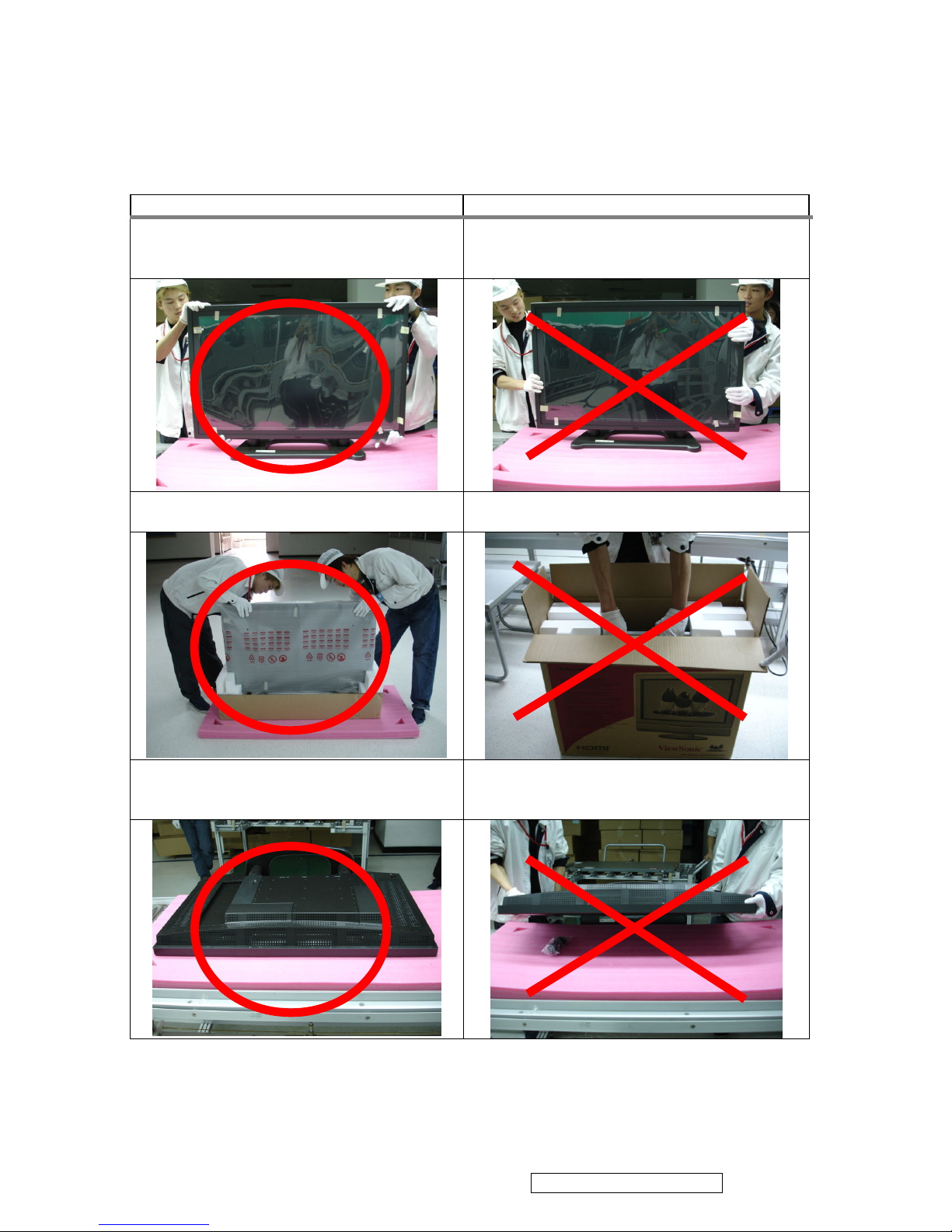
2. Handling and Placing Methods
Correct Methods: Incorrect Methods:
Only touch the metal frame of the LCD panel
or the front cover of the LCD TV. Do not
touch the surface of the polarizer.
Surface of the LCD panel is pressed by fingers
and that may cause “Mura”.
Take out the LCD TV with cushions. Take out the LCD TV by grasping the LCD
panel. That may cause ”Mura”.
Place the LCD TV on a clean and soft foam
pad.
Place the LCD TV on foreign objects. That
could scratch the surface of the panel or cause
“Mura”.
ViewSonic Corporation Confidential - Do Not Copy N4200w-1
5
2. Service tool & equipment required
1. signal generator
2. multimeter
3. oscilloscope
4. screw driver
5. iron
6. absorber
7. solder
8. DVD player
9. Debug board (connect to PC via null-modem RS-232 serial cable)
10. D8330 PCI Card, VGA cable, DVI
to HDMI cable, VGA RS-232 cable, DVI RS-232 cable
3. Specification
3.1 Product Specification
LCD Type 42.02” view able
Color Filter 0.681 mm (H) x 0.227 (V) mm pixel pitch
Glass surface RGB vertical stripe
Anti-Glare
Input signal RGB RGB analog (0.7/1.0 Vp-p, 75 ohms)
Separate Sync,
fh:30-80 kHz, fv:50-75 Hz
Video D-sub x 1 ,HDMI x 2, YPbPr/YCbCr x 2, S-Video x 2,
CVBS x 2
Audio Mini-stereo (Φ3.5mm x 1 ), RCA (L/R) x 4
Compatibility PC Up to 1360 x 768 Non-interlaced
Resolution 1360 x 768 @ 60 Hz
Speaker Output 10W x 2
Power Voltage 90-240 VAC, 50/60 Hz
Display area Full Scan 930.25mm (H) x 523.01 mm (V)
36.62 inch (H) x 20.59 inch (V)
Operating Temperature 32° F to + 104° F (0° C to + 40° C)
conditions Humidity 0% to 95% (no condensation)
Altitude To 10,000 feet (3,000m)
Storage Temperature -4° F to + 140° F (-20° C to + 60° C)
conditions Humidity 0% to 95% (no condensation)
Altitude To 40,000 feet (12,000m)
Dimensions Physical 1243 mm (W) x 739 mm (H) x 304mm (D)
48.93 inch (W) x 29.09 inch (H) x 11.96 inch (D)
Weight Net 33kg (72.68 lb)
Regulations FCC, UL, cUL, NOM
Power saving On <240 W LED Green
modes Passive Off <3 W LED Red
Pre-test Timing Mode (Pre-adjusted to GTF 1360 x 768@60Hz)
ViewSonic Corporation Confidential - Do Not Copy N4200w-1
6
Warning: Do not set the graphics card in your computer to exceed these refresh rates; doing so may result in permanent
damage to the LCD display.
Note: Product specification is subject to change without notice.
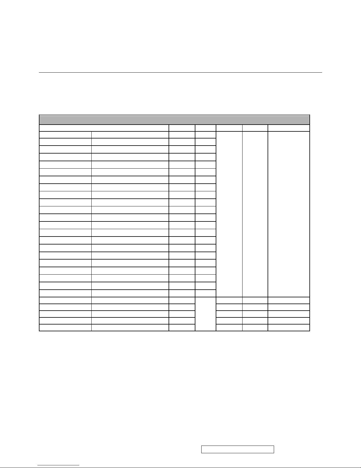
3.2 Factory supporting modes
Supporting Modes
Mode HDMI RGB YPbPr SVHS Composite
Standard Resolution
720╳400@60Hz
Yes Yes
720╳400@70Hz
Yes Yes
720╳480@60Hz
Yes Yes
640╳480@60Hz
Yes Yes
640╳480@72Hz
Yes Yes
640╳480@75Hz
Yes Yes
800╳600@56Hz
Yes Yes
VESA
800╳600@60Hz
Yes Yes
800╳600@72Hz
Yes Yes
VESA
800╳600@75Hz
Yes Yes
MAC
832╳624@75Hz
Yes Yes
VESA
1024╳768@60Hz
Yes Yes
1024╳768@70Hz
Yes Yes
VESA
1024╳768@75Hz
Yes Yes
1280╳720@60Hz
Yes Yes
1280╳720@75Hz
Yes Yes
VESA
1280╳768@60Hz
Yes Yes
1280╳768@75Hz
Yes Yes
VESA
1280╳1024@60Hz
Yes Yes
1280╳1024@75Hz
Yes Yes
1360╳768@60Hz
Yes Yes
--- --- ---
DVD 480i(60Hz) Yes Yes Yes Yes
480p(60Hz) Yes Yes
720p(50Hz) Yes Yes
720p(60Hz) Yes Yes
1080i(60Hz) Yes Yes
ViewSonic Corporation Confidential - Do Not Copy N4200w-1
7
3.3 D-SUB and HDMI Connector
Connector pin assignments for VGA cable
The signal cable connector shall be a molded-over, shield twisted pair cable. The cable shall be 1.8 meters
long. The pin assignments shall be listed as below:
Pin No. Per DDC2B
1 Red Video
2 Green Video
3 Blue Video
4 GROUND
5 GROUND
6 Red Video Ground
7 Green Video Ground
8 Blue Video Ground
9 Mandatory +5V Supply for PC Bypass
10 Sync. Ground
11 GROUND
12 Bi-directional Data (SDA) for PC Bypass
13 Horizontal Sync.
14 Vertical Sync.
15 Data Clock (SCL) for PC Bypass
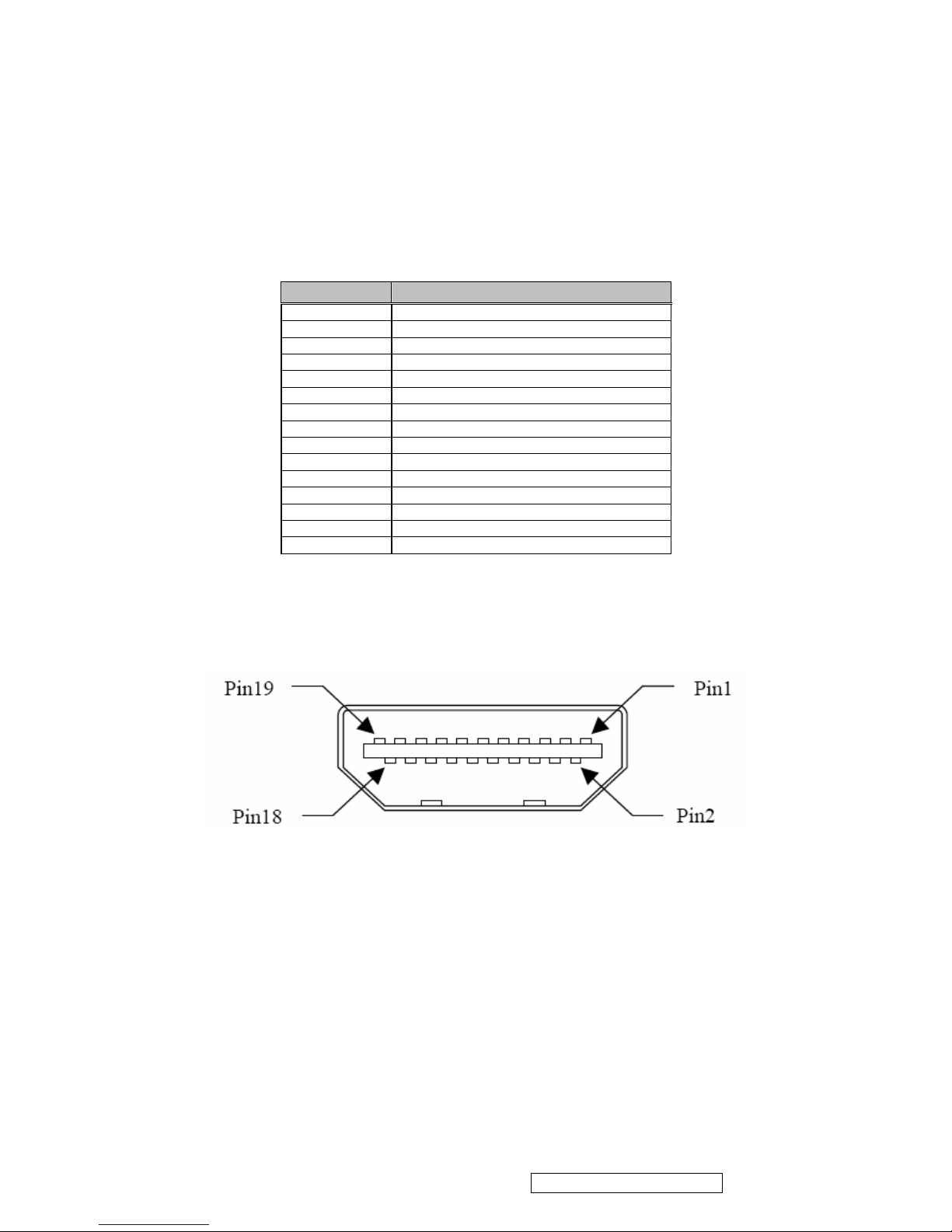
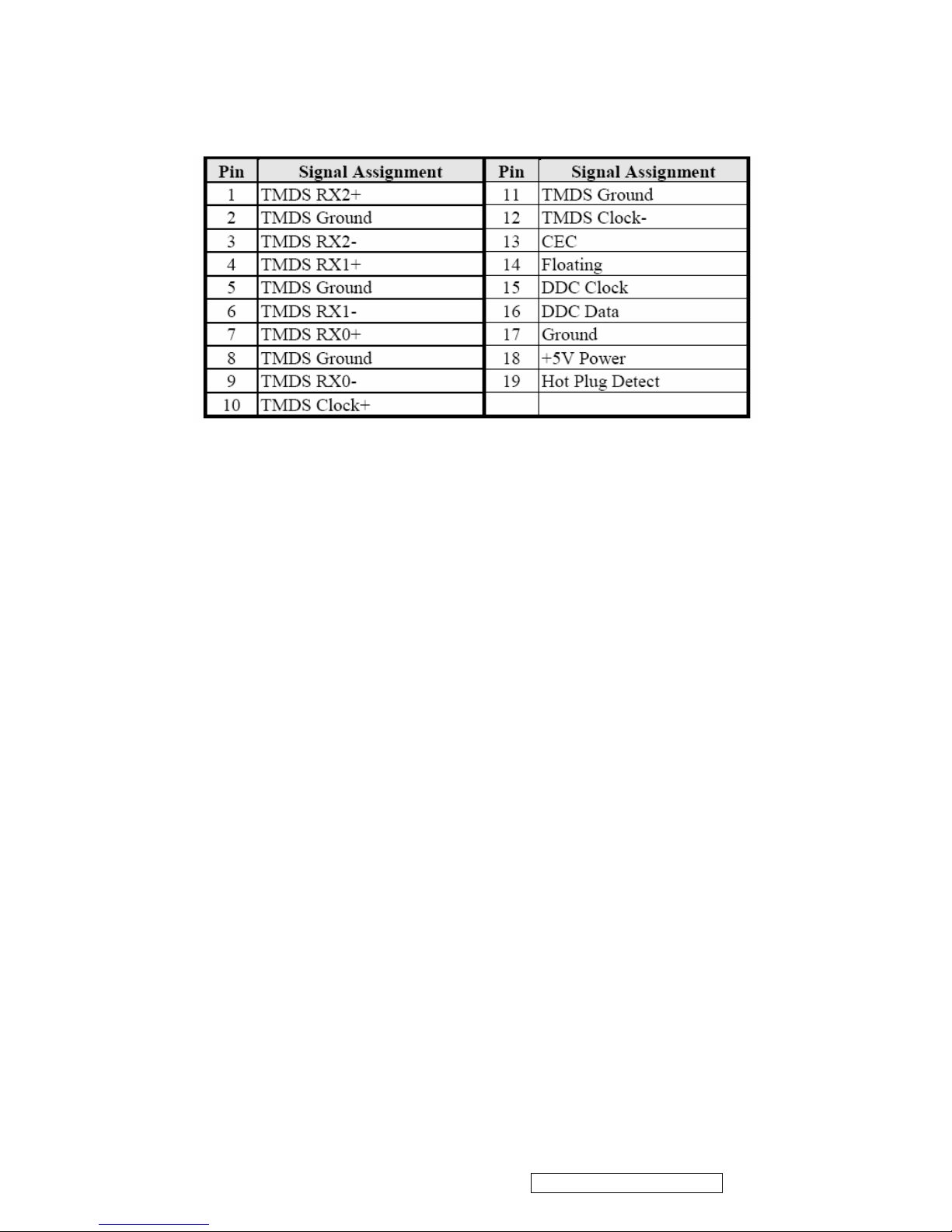
Connector pin assignments for HDMI cable
HDMI: 19 pins HDMI connector is designed to match with HDMI digital signal cable, the pin assignment is
as the following:
ViewSonic Corporation Confidential - Do Not Copy N4200w-1
8
ViewSonic Corporation Confidential - Do Not Copy N4200w-1
9
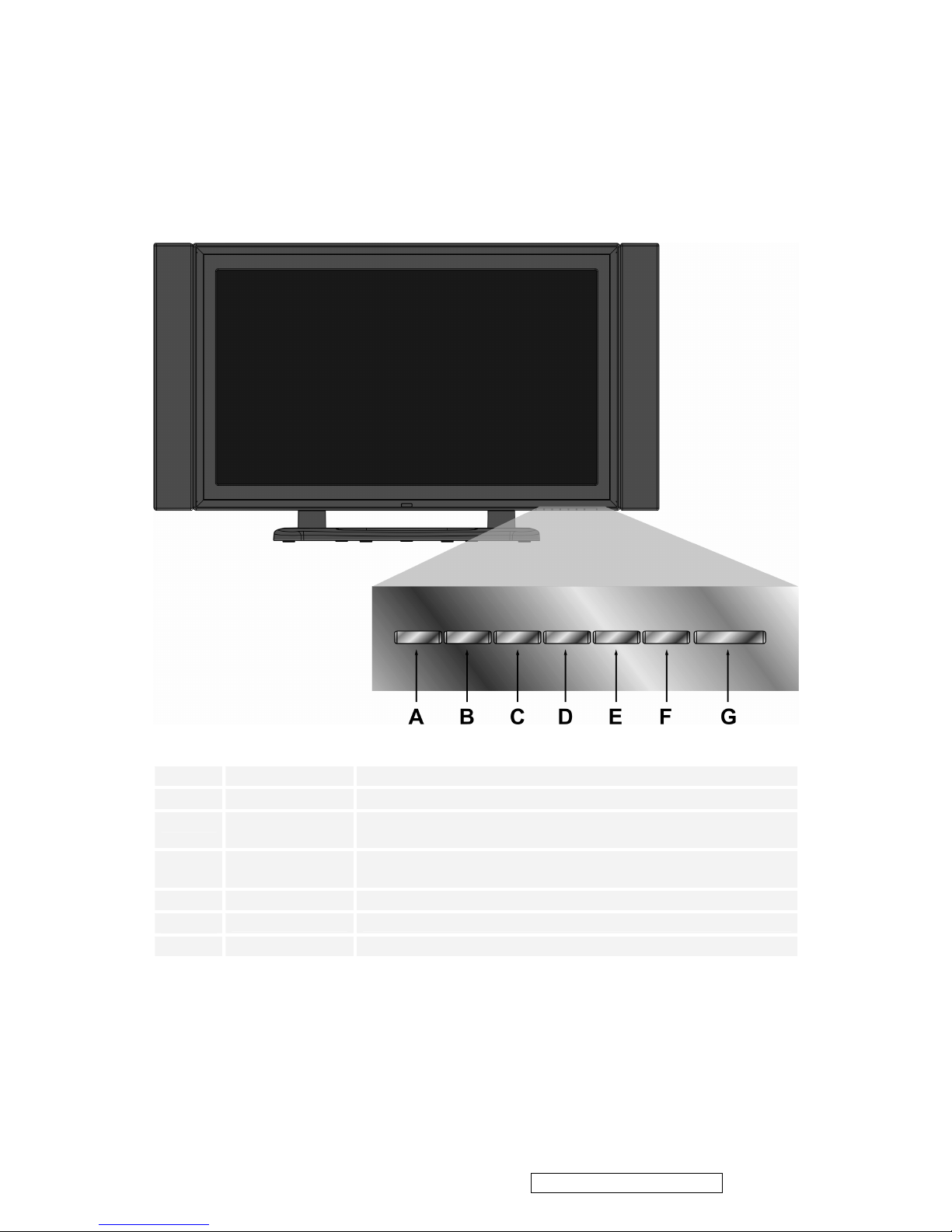
4. Front Panel Function Control Description
4.1 Front View
A
Input
Select input sources
B
MENU
Turn OSD menu ON/OFF
C
Volume Down
Decrease volume or adjust a highlighted control decreasingly
while in OSD menu
D
Volume Up
Increase volume or adjust a highlighted control increasingly
while in OSD menu
E
CH Down
Channel down/ Scroll down
F
CH Up
Channel up/ Scroll up
G
Power
Turn the power ON/OFF
ViewSonic Corporation Confidential - Do Not Copy N4200w-1
10
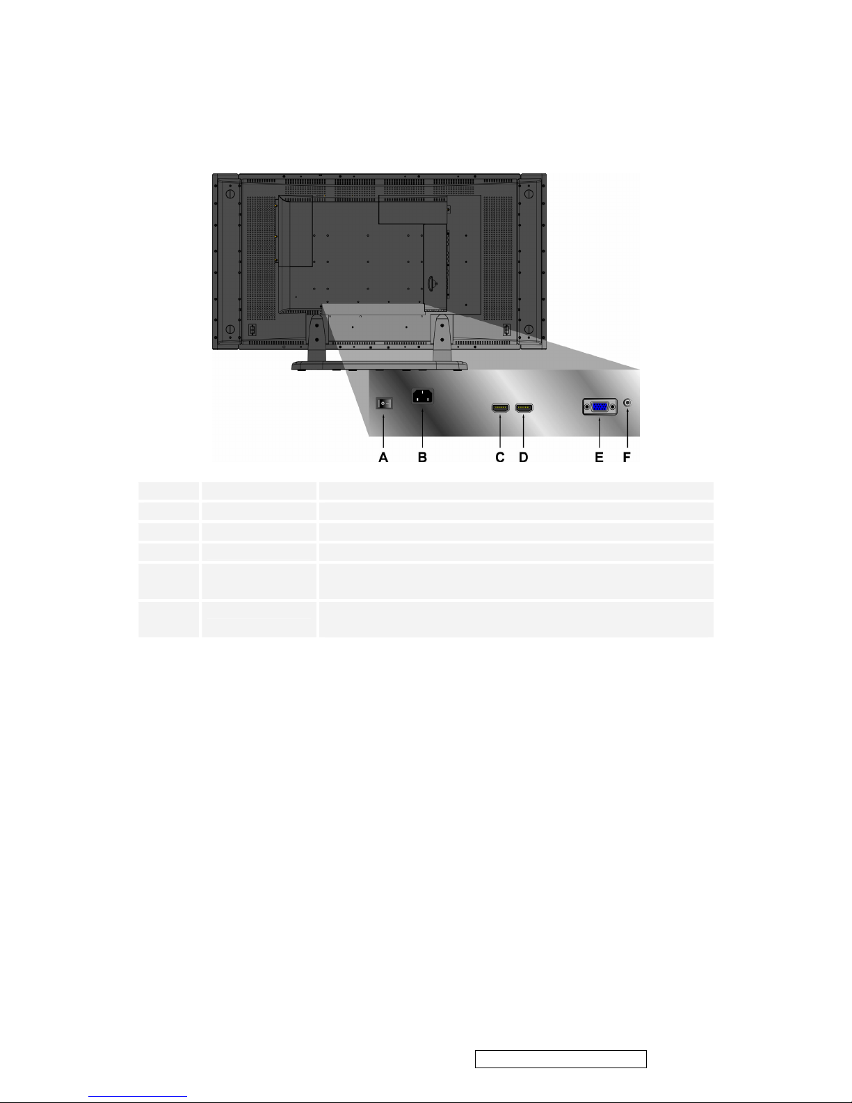
4.2 back View
A
POWER S/W
Power S/W
B
AC IN
Using cable provided, connect a power source.
C
HDMI(1)
Have one HDMI cable terminals of your DVD player.
D
HDMI(2)
Have one HDMI cable terminals of your DVD player.
E
VGA
Connect the VGA cable output of PC to the VGA terminal
input.
F
PC STEREO
Connect the Audio in cable from audio output of your PC
to the audio input terminal.
ViewSonic Corporation Confidential - Do Not Copy N4200w-1
11
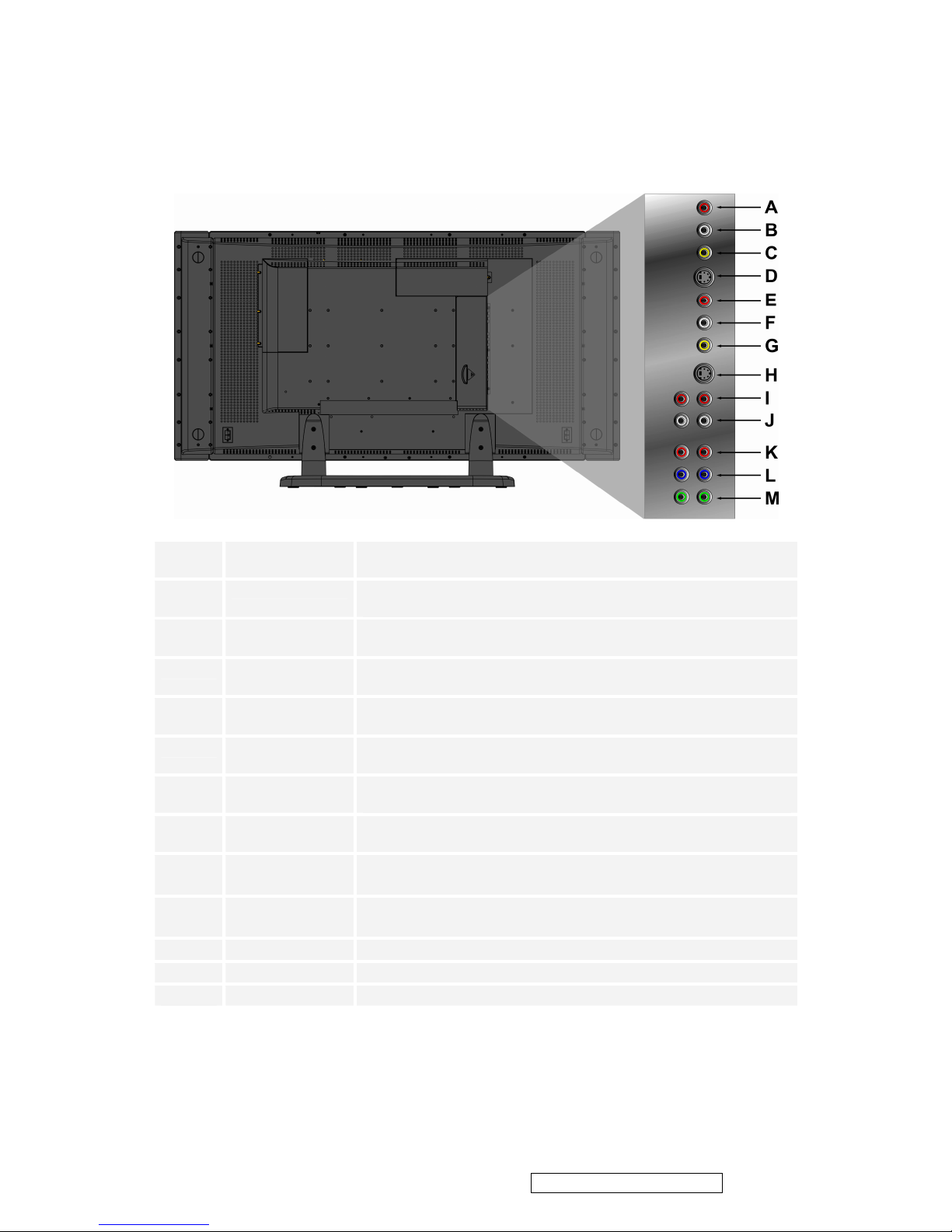
4.3 Side View
A
R
Connect Video/Audio cable from compatible devices into the
side jack.
B
L
Connect Video/Audio cable from compatible devices into the
side jack.
C
VIDEO
Connect the external video device such as VCR, DVD, and
video game into this jack.
D
S-V1
Connect the external video device such as VCR, DVD, and
video game into this jack.
E
R
Connect Video/Audio cable from compatible devices into the
side jack.
F
L
Connect Video/Audio cable from compatible devices into the
side jack.
G
VIDEO
Connect the external video device such as VCR, DVD, and
video game into this jack.
H
S-V2
Connect the external video device such as VCR, DVD, and
video game into this jack.
I
R
Connect Audio cable from compatible devices into the
side jack.
J
L
Connect Audio cable from compatible devices into the
side jack.
K
Pr/Cr
Connect the external video device into this jack.
L
Pb/Cb
Connect the external video device into this jack.
M
Y
Connect the external video device into this jack.
ViewSonic Corporation Confidential - Do Not Copy N4200w-1
12

5. Adjustment Procedure
5.1 Setup Conditions and Precautions
5.1.1 Adjustments should be undertaken only on those necessary elements since most of them have
been carefully preset at the factory.
5.1.2 ESD protection is needed before adjustment.
5.2 Main Adjustments
NO. FUNCTION DESIGNATION
1. EEPROM Initial Function Key
2. Do calibration Function Key
5.3 Alignment Procedures
Adjustment Conditions and Precautions:
(A). Power supply voltage:
AC 110/120V±10% 60 Hz±5%, AC 220/240V±10% 50 Hz±5%.
(B). Signals: reference the front detail specifications and timing table.
Video: refer to the specifications given.
(C) Do calibration before test VGA or HDTV.
5.3.1 EEPROM Initial:
A. Switch on the AC-in Power Switch (POWER S/W).
B. Make sure the system is Power on status.
C. Do “Factory Preset” under the OSD Setup menu.
D. Press the “POWER” key to turn off system.
E. Press the “POWER” key to turn on system.
5.3.2. Calibration in VGA or HDTV source Adjustment:
(1) VGA calibration verification:
A. Timing: 1280x720@60Hz.
B. Pattern: 16 gray.
C. Connect VGA port to VG-849 or VG859
D. Press “INPUT” key to open the “Main Source Input” Menu, then select “VGA” item.
E. Press “Power” Key, then the system is soft-power-off status.
F. Press the “VOL-”, “VOL+” and “MENU” key simultaneously, and press the “POWER” key to turn on the
system. At this time, the system enters the factory mode.
G: Press “MENU” key to enter the “FACTORY OSD”.
H. Press “CHT” key to select the “Analog RGB Calibration” item in the factory OSD, and press “VOL+”
key then the Calibration will be auto adjusted.
ViewSonic Corporation Confidential - Do Not Copy N4200w-1
13

I. After Step H, check Gray Patten on both Main Window and Sub Window with VGA signal. If Color Shift
exists or Gray Step Saturation is abnormal, do Step A~H again.
(2) HDTV calibration verification:
A. Timing: 720p@60Hz.
B. Pattern: SMPTE bar.
C. Connect HDTV1 ports to VG-849 or VG859
D. Press “INPUT” key to open the “Main Source Input” Menu, and then select the “HDTV1” item.
E. Press “Power” Key, then the system is soft-power-off status.
F. Press the “VOL-”, “VOL+” and “MENU” key simultaneously, and press the “POWER” key to turn on the
system. At this time, the system enters the factory mode.
G. Press “MENU” key to enter the “FACTORY OSD”.
H. Press “CHT” key to select the “YCbCr Calibration” item in the factory OSD, and press “VOL+” key
then the Calibration will be auto adjusted.
I. After Step H, check Gray Patten on both Main Window and Sub Window with HDTV1(YPbPr) signal. If
Color Shift exists or Gray Step Saturation is abnormal, do Step A~H again.
5.4 Adjusting Procedures
5.4.1 Function Test
□Video/Audio Receiving Test
I. PC FUNCTION CHECK
- Test Equipment
Color Video Signal & Pattern (or PC with SXGA resolution and a sound card)
- Test Condition
Before function test and alignment, each LCD TV should be warmed up for at least 30 minutes with the
following conditions:
(a) In room temperature,
(b) With full-white screen, RGB, and Black
(c) With cycled display modes,
640*480 (H=43.27kHz, V=85Hz)
800*600 (H=53.7kHz, V=85Hz)
1024*768 (H=68.67kHz, V=85Hz)
1280*1024 (H=79.97kHz, V=75Hz)
ViewSonic Corporation Confidential - Do Not Copy N4200w-1
14
- Test Display Modes & Pattern
Mode Compatibility Table-N4200w-1M
Analog Digital
1. 720 x 400 @ 70Hz 1. 720 x 400 @ 70Hz
2. 640 x 480 @ 60Hz 2. 640 x 480 @ 60Hz
3. 640 x 480 @ 75Hz 3. 640 x 480 @ 75Hz
4. 800 x 600 @ 60Hz 4. 800 x 600 @ 60Hz
5. 800 x 600 @ 75Hz 5. 800 x 600 @ 75Hz
6. 832 x 624 @ 75Hz 6. 832 x 624 @ 75Hz
7. 1024 x 768 @ 60Hz 7. 1024 x 768 @ 60Hz
8. 1024 x 768 @ 75Hz 8. 1024 x 768 @ 75Hz
9. 1280 x 720 @ 60Hz 9. 1280 x 720 @ 60Hz
10. 1280 x 768 @ 60Hz 10. 1280 x 768 @ 60Hz
11. 1280 x 1024 @ 60Hz 11. 1280 x 1024 @ 60Hz
12. 1360 x 768 @ 60Hz 12. 1360 x 768 @ 60Hz
Function Test Display Pattern
Item Test C o nt e nt Pattern Specification Remark
1
Frequency and
Tracking
Fine Line Moire Eliminate visual wavy noise
Figure 1
2 Contrast/Brightness 16 Gray Scale
16 gray levels should be
distin
g
uishable
Figure 2
3
Boundary
Horizontal and
Ve r t ic a l
Thickness
Horizontal and Vertical position of
video should be adjustable to be
within the screen frame
Figure 3
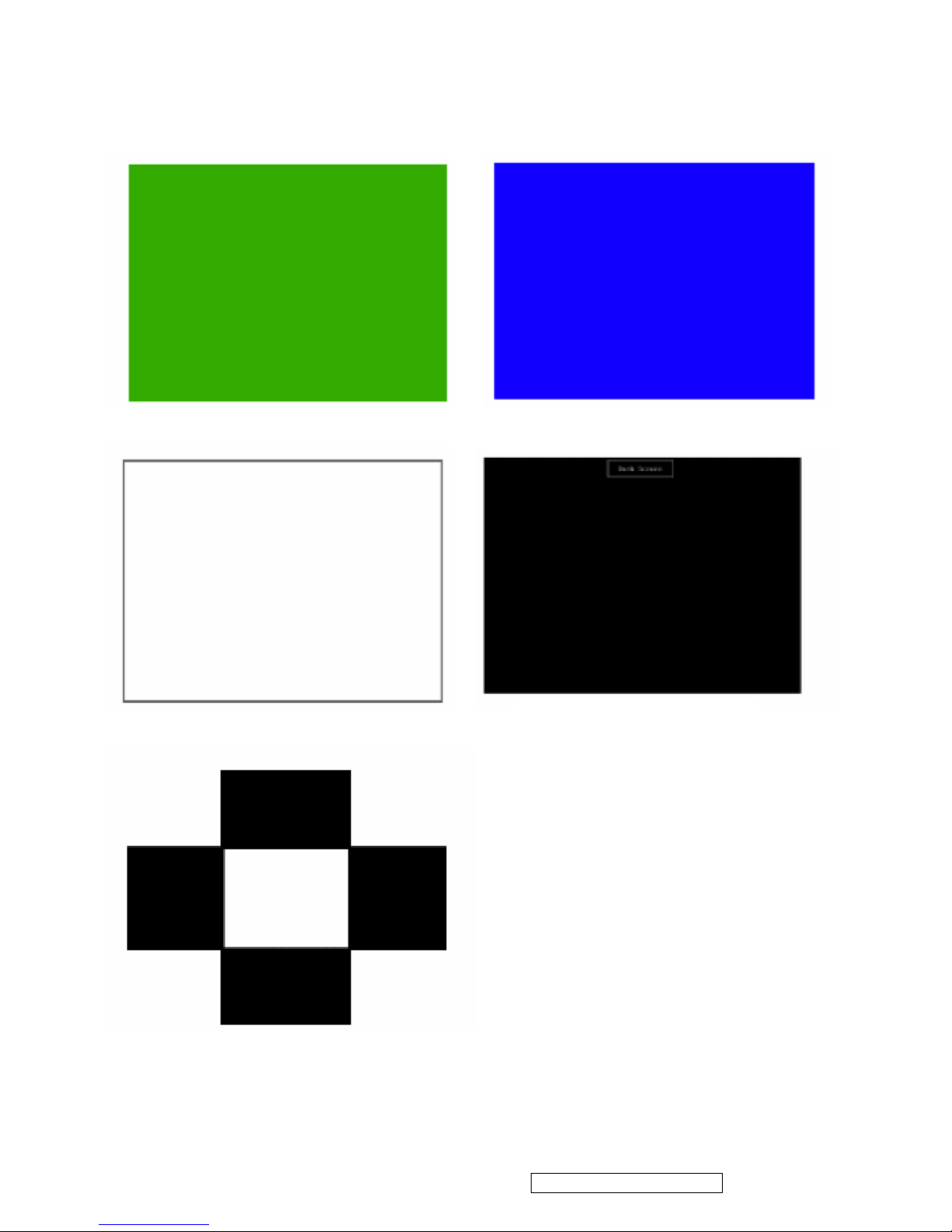
4 RGB Color
Performance
RGB Color
Intensities
Contrast of each R, G, B, color
should be normal.
Figure 4, 5, 6
5 Screen Uniformity
and Flicke
r
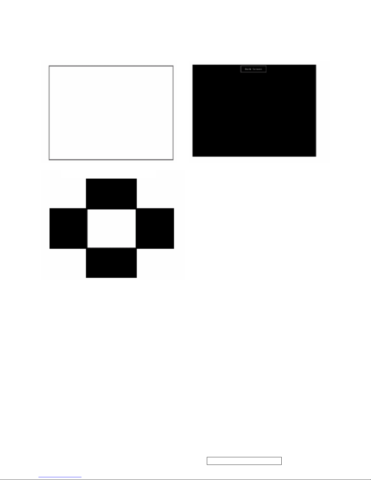
Full White
Should be compliant with the spec Figure 7
6
Dead Pixel/Line
White Screen and
Dark Screen
The numbers of dead pixels should
be compliant with the spec
Figure 7, 8
7 White Balance
White and Black
Pattern
Figure 9
ViewSonic Corporation Confidential - Do Not Copy N4200w-1
15

Horizontal & Vertical Thickness Pattern (Figure 3) R.Color Pattern (Figure 4)
Fine Line Morie Pattern (Figure 1) Gray Scale Pattern (Figure 2)
G. Color Pattern (Figure 5) B. Color Pattern (Figure 6)
ViewSonic Corporation Confidential - Do Not Copy N4200w-1
16
II.YPBPR FUNCTION CHECK
- Test Equipment
DVD player
SIGNAL DIVIDER
- Test Condition
Before function test and alignment, each LCD TV should be warmed up for at least 30 minutes with the
following conditions:
(a) In room temperature,
(b) With full-white screen, RGB, and Black
(c) With cycled display modes,
Full White Pattern (Figure 7) Dark Screen Pattern (Figure 8)
Black-White Pattern (Figure 8)
ViewSonic Corporation Confidential - Do Not Copy N4200w-1
17

- Test Display Modes & Pattern
1. Connector HDTV Signal to Interface YPbPr
2. Check Picture
Unclear color steps, snowinterference , unclear gray steps ,water waves and unclear crosstalk can not
happen. Picture must be vivid and clear. Audio must have no noise.
ViewSonic Corporation Confidential - Do Not Copy N4200w-1
18
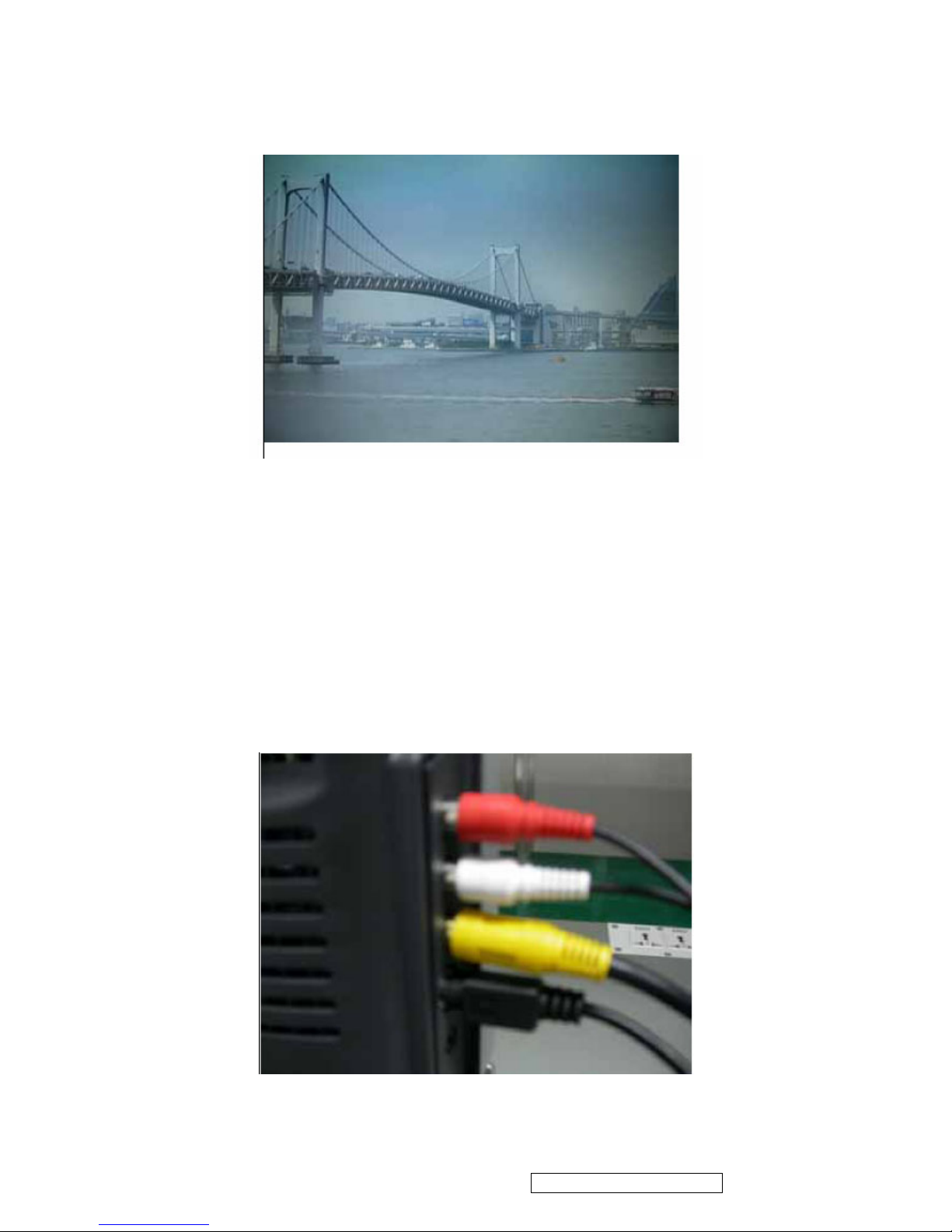
III. AV, S-VIDEO INTERFACE FUNCTION TEST
- Test Equipment
DVD player
- Test Condition
Before function test and alignment, each LCD TV should be warmed up for at least 30 minutes with the
following conditions:
(a) In room temperature,
(b) With full-white screen, RGB, and Black
(c) With cycled display modes,
- Test Display Modes & Pattern
ViewSonic Corporation Confidential - Do Not Copy N4200w-1
19

Connector Figure
Unclear color steps, snow interference , unclear gray steps ,water waves and unclear crosstalk can not
happen. Picture must be vivid and clear. Audio must have no noise.
IV. HDMI INTERFACE FUNCTION TEST
- Test Equipment
1. PC
2. VG859A
ViewSonic Corporation Confidential - Do Not Copy N4200w-1
20
- Test Condition
Before function test and alignment, each LCD TV should be warmed up for at least 30 minutes with the
following conditions:
(a) In room temperature,
(b) With full-white screen, RGB, and Black
(c) With cycled display modes,
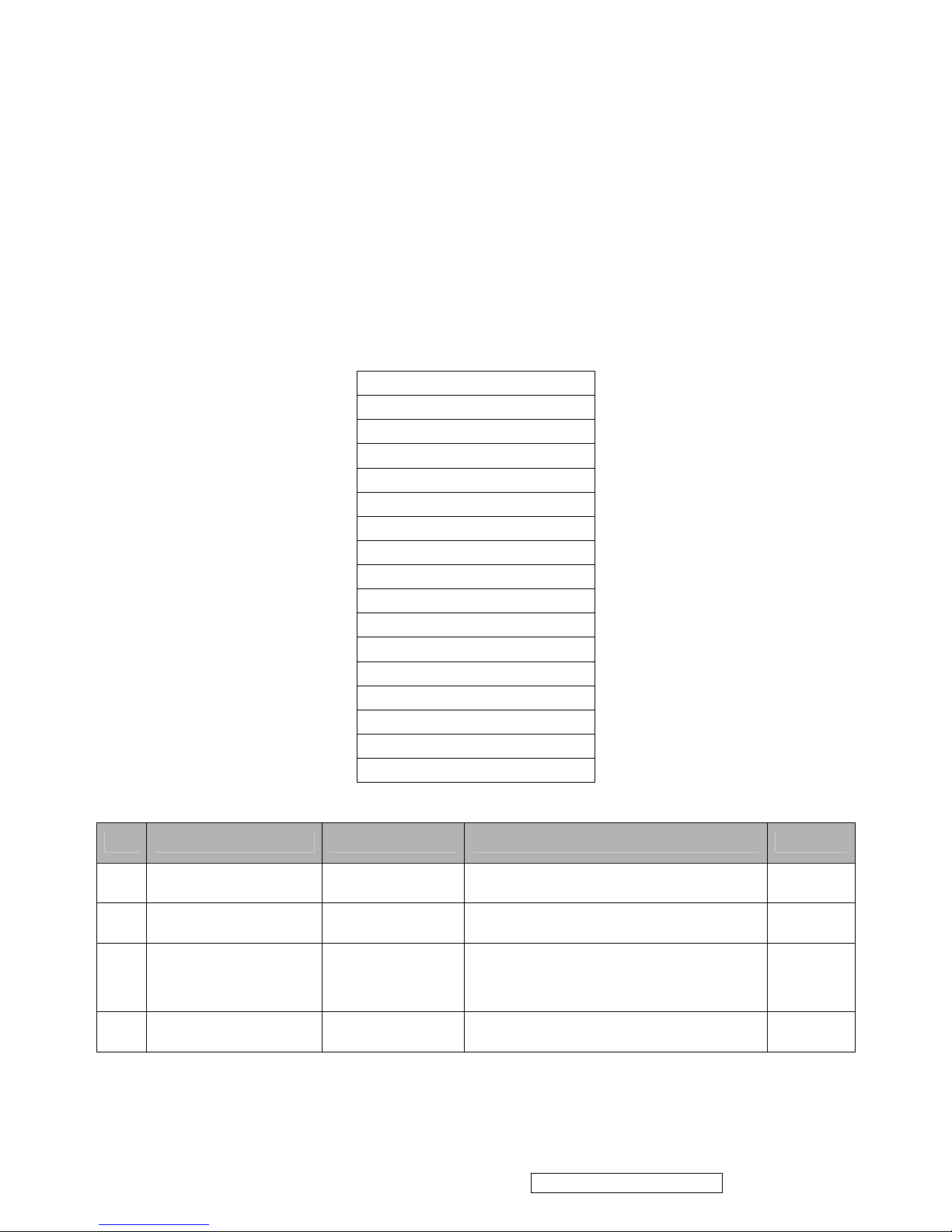
- Test Display Modes & Pattern
Mode Compatibility Table
1. 720 x 400 @ 70Hz
2. 640 x 480 @ 60Hz
3. 640 x 480 @ 75Hz
4. 800 x 600 @ 60Hz
5. 800 x 600 @ 75Hz
6. 832 x 624 @ 75Hz
7. 1024 x 768 @ 60Hz
8. 1024 x 768 @ 75Hz
9. 1280 x 720 @ 60Hz
10. 1280 x 768 @ 60Hz
11. 1280 x 1024 @ 60Hz
12. 1360 x 768 @ 60Hz
13. 480I(60Hz)
14. 480p(60Hz)
15. 720p(50Hz)
16. 720p(60Hz)
17. 1080i(60Hz)
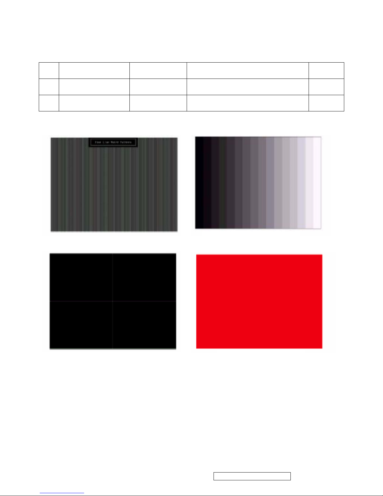
Function Test Display Pattern
Item Te s t Con tent Pattern Specification Remark
1
Frequency and
Tracking
Fine Line Moire Eliminate visual wavy noise Figure 1
2
Contrast/Brightness
16 Gray Scale 16 gray levels should be
distin
g
uished by bare eyes
Figure 2
3
Boundary
Horizontal and
Ve r t ic a l
Thickness
Horizontal and Vertical position of video
should be adjustable within the screen
frame
Figure 3
4
RGB Color
Performance
RGB Color
Intensities
Contrast of each R, G, B, color
should be normal
Figure 4,
5, 6
ViewSonic Corporation Confidential - Do Not Copy N4200w-1
21
5
Screen Uniformity &
Flicke
r
Full White
Should be compliant with the spec Figure 7
6
Dead Pixel/Line
White Screen and
Dark Screen
The numbers of dead pixels should
b
e compliant with the spec
Figure 7,
8
7
White Balance
White and Black
Pattern
Figure 9
Horizontal & Vertical Thickness Pattern (Figure 3)
R.Color Pattern (Figure 4)
Fine Line Morie Pattern (Figure 1)
Gray Scale Pattern (Figure 2)
ViewSonic Corporation Confidential - Do Not Copy N4200w-1
22
G. Color Pattern (Figure 5) B. Color Pattern (Figure 6)
Full White Pattern (Figure 7)
Dark Screen Pattern (Figure 8)
Black-White Pattern (Figure 8)
ViewSonic Corporation Confidential - Do Not Copy N4200w-1
23

□COLOR TEMPERATURE ADJUSTING
HD Mode
A. Test Equipment: CA210. Astro 859
B. Timing: 1920*1080@60Hz
C. Pattern: full white
D. LCD TV should be run-in and warmed up for at least 30 minutes.
E. Color temperature adjusting.
F. Color temperature verification.
Warm x= 0.3±0.03 y= 0.31±0.03
STD x= 0.285 y= 0.293
Cold x=0.274 y=0.286
VGA Mode
A. Test Equipment: CA210. Astro 859
B. Timing: 1024*768@60Hz
C. Pattern: full white
D. LCD TV should be run-in and warmed up for at least 30 minutes.
E. Color temperature adjusting.
F. Color temperature verification.
Warm x=0.3±0.03 y=0.31±0.03
STD x=0.285 y=0.293
Cold x=0.274 y=0.286
HDMI Mode:
A. Test Equipment: CA210. Astro 859
B. Timing: 1280*720@60Hz
C. Pattern: full white
D. LCD TV should be run-in and warmed up for at least 30 minutes.
E. Color temperature adjusting.
F. Color temperature verification.
Warm x=0.3±0.03 y=0.31±0.03
STD x=0.285 y=0.293
Cold x=0.274 y=0.286
□POWER SAVING TEST
A. Timing: Video mode: 480i /PC mode: 640*480@75Hz.
B. Pattern: ColorBar.
C. BRIGHTNESS=MAX, CONTRAST=MAX.
D. The power that each MODE consumes is shown in Chart 1.
Mode Max Power consumed Power LED Color
Power On <240W GREEN
ViewSonic Corporation Confidential - Do Not Copy N4200w-1
24
Power Saving ORANGE
Soft Power Off <3W RED
Chart 1
□OSD FUNCTION CHECK
A. Timing: Video mode: 480i / PC mode: 640*480@75Hz.
B. Pattern: ColorBar.
C. Make sure that each FUNCTION have right action.
D. After adjusting and confirming no error, we can deliver the LCD display until it set as
default.
□VIDEO RECEIVING TEST
AV receives supply oscillator: AV1/AV2/S-Video1/S-Video2/HDMI1/HDMI2/HDTV1/HDTV2 are from
DVD to LCD TV; Examines whether the image and the sound is normal.
(1)AV1/AV2: Video cable (Yellow), Audio cable (Left(White), Right(Red)sound track).
(2)S-Video1/S-Video2: S-Video signal cable (
Yellow), Audio cable ( Left(White), Right(Red) sound track).
(3)VGA: D-sub cable (Black)
(4)HDMI1/HDMI2: HDMI cable (Black)
(5)HDTV1/HDTV2 (YPbPr/YCbCr): brightness signal cable (Green), Component signal cable(Red, Blue),
Audio cable(Left(White), Right(Red)sound track).
□VIDEO/AUDIO OUTPUT TEST
(1) HDTV/AV output: A 42” LCD display in AV pattern, inputs the CVBS signal; the output meets HDTV,
HDTV links to another 42” LCD display sending HDTV pattern. Examines two 42” LCD display
whether they show same images. But their sound doesn’t affect each other and could adjust volume
respectively to examine. AV output test are likewise.
(2) With extra amplifiers, audio output should still work under any pattern except PC pattern.
□FAC T ORY PR ESE T
After final QC step, we have to erase all saved changes again and restore the factory defaults.
You should do “Factory Preset” again.
Select “Factory Preset” from OSD.
Power off the LCD display.
Turn off the LCD display by pressing “Power” button.
ViewSonic Corporation Confidential - Do Not Copy N4200w-1
25
 Loading...