

ViewSonic VS10848-1M, N3260w, N3260wM, N3760w, N3760wM Service Manual
...
Service Manual
ViewSonic N3260w(M)
N3760w(M)
N4060w(M)
Model No. VS10847-1M
VS10848-1M
VS10846-1M
32” 37” 40” LCD TV
(N3260w_N3760w_N4060w-1M_SM_Rev.1a_Mar.2006)
ViewSonic® 381 Brea Canyon Road, Walnut, California 91789 USA - (800) 888-8583
ViewSonic Corporation Confidential - Do Not Copy N3260w_N3760w
N4060w
1
Copyright
Copyright © 2006 by ViewSonic Corporation. All rights reserved. No part of this publication may be
reproduced, transmitted, transcribed, stored in a retrieval system, or translated into any language or
computer language, in any form or by any means, electronic, mechanical, magnetic, optical, chemical,
manual or otherwise, without the prior written permission of ViewSonic Corporation.
Disclaimer
ViewSonic makes no representations or warranties, either expressed or implied, with respect to the contents
hereof and specifically disclaims any warranty of merchantability or fitness for any particular purpose. Further,
ViewSonic reserves the right to revise this publication and to make changes from time to time in the contents
hereof without obligation of ViewSonic to notify any person of such revision or changes.
Trademarks
Optiquest is a registered trademark of ViewSonic Corporation.
ViewSonic is a registered trademark of ViewSonic Corporation.
All other trademarks used within this document are the property of their respective owners.
Revision History
Revision SM Editing Date ECR Number Description of Changes Editor
1a 2006/03/30 Initial Release Sophia Kao

TABLE OF CONTENTS
1. Precautions and Safety Notices 3
2. Specification 6
3. Front Panel Function Control Description 9
4. Circuit Description 10
5. Adjustment Procedure 19
6. Trouble Shooting Flow Chart 22
7. Block Diagram 25
8. PCB Layout Diagrams 26
9. Schematic Diagrams 30
10. Exploded Diagram and Exploded Parts List 55
11. Recommended Spare Parts List 61
ViewSonic Corporation Confidential - Do Not Copy N3260w_N3760w
N4060w
2

1. Precautions and Safety Notices
All rights reserved. No part of this publication may be reproduced, transmitted, transcribed,
stored in a retrieval system or translated into any language in any form or by any means,
electronic, mechanical, magnetic, optical, chemical, manual, or otherwise, without the prior
permission of the company.
Disclaimer
We make no representations or warranties, either expressed or implied, with respect to the
contents of this document, and specifically disclaims any warranties, merchantability or fitness
for any particular purpose. Further, reserves the right to revise this publication and make
changes in the contents without obligation to notify any person of such revision or change.
All rights reserved
VGA and XGA are registered trademarks of International Business Machines Co. Inc.
Product safety notice
Many electrical and mechanical parts in this product include specific, safety related
characteristics. These characteristics may not be immediately obvious by visual inspection and
the protection these components offer can not necessarily be obtained using replacement
components with the same voltage or power ratings.
offer can not necessarily be obtained using replacement components with the same voltage or
power ratings. Electrical components having such features are identified by shading on the
schematic diagram and in the parts list. Before replacing components, read the parts list in this
manual thoroughly.
The use of substitute parts which do not have the same safety characteristics as those indicated
in the parts list may cause electrical shock, fire, x-ray emissions, or other hazards.
Service notes
1. When replacing circuit boards or components, clamp the lead wires to the terminals before
soldering.
2. When replacing a high power resistor (oxide metal film resistor) on a circuit board, keep the
resistor at least 10 mm (0.5-inch) from the circuit board.
3. Keep leads and wires away from high voltage and high temperature components.
4. If any fuse in the product is blown, replace it only with the correct fuse specified in the parts
list.
Handling of broken glass and liquid crystal leakage
If the LCD is damaged, liquid crystal leakage may occur and the glass may shatter into small pieces. Do
not touch the broken glass or liquid crystal which is toxic. In addition to possible cuts resulting from
broken glass, toxic leakage may cause skin irritation or poisoning. If liquid crystal enters your eyes or
mouth, you should immediately rinse with clean water and consult a doctor.
Important safety information
1. Read all these instructions.
ViewSonic Corporation Confidential - Do Not Copy N3260w_N3760w
N4060w
3

2. Save these instructions for later use.
3. Unplug this television set from the wall outlet before cleaning.
4. Do not use accessories not recommended in the user manual as they may damage the product.
5. Do not use this product in wet locations such as near a bathtub, washbowl, kitchen sink, laundry
tub, swimming pool, or in a wet basement
6. Do not place this product on an unstable cart, stand, or table. The television receiver may fall
and causeserious injury as well as possibly damaging the product. Use only with a cart or
stand recommended serious injury as well as possibly damaging the product. Use only with a
cart or stand recommended instructions and only use a mounting kit as recommended by the
manufacturer.
7. Blocking the ventilation holes can cause overheating and fire. Take care not to block any
ventilation holes when siting the television close to walls or other objects. Never install this
product in a closed cabinet or bookcase unless sufficient ventilation is provided.
8. This television should be operated using only the type of power source indicated on the label
and in the user manual. If you are unsure what your home power supply is, you should
consult the Power Company or talk to your television dealer.
9. This television is equipped with a plug designed to fit only one way in the power socket. The
earth pin is an important safety feature of the plug. If the plug does not fit your outlets or your
outlets do not include a hole for the earth pin, you should consult a qualified electrician about
replacing the socket.
10. Do not rest anything on the power cord and do not allow the power cord to lie in a position
where it is likely to be stepped on or tripped over.
11. Follow all warnings and instructions marked on the television receiver.
12. During thunderstorms and when the television is unused for extended periods of time, you
should unplug the power cord from the outlet and disconnect the antenna.
13. External antenna systems should be sited away from overhead power lines and away from
electrical circuits. Extreme caution should be exercised when erecting an outside antenna.
Touching overhead power cables can be fatal.
14. Do not overload power outlets or extension cords as fire or electric shock can result.
15. Never push anything into the television through the ventilation slots as they may come into
contact with high voltage elements of the device and cause electric shock or fire. Take care
never to spill liquids into the product.
16. Servicing of this product should only be carried out by qualified service technicians.
17. Unplug this product from the power source and consult a qualified service technician in the
following
cases:
• The power cord is damaged or frayed.
• Liquid is spilled into the television.
• The television is exposed to rain or water.
• The television does not operate as the user manual describes. In this case, use only
ViewSonic Corporation Confidential - Do Not Copy N3260w_N3760w
N4060w
4

the controls covered by the operating instructions. Improper adjustment of this equipment
using controls not covered in the user manual may result in damage to the product that may
require extensive work by qualified technicians to rectify.
• The television or cabinet is damaged.
• The television shows a change in performance that indicates a need for servicing.
18. When replacement parts are used, ensure that the technician uses only parts recommended
by the manufacturer. Unauthorised replacement parts may cause a fire or electric shock.
19. After servicing, ensure that the technician performs routine safety checks to determine
whether the television is in a safe operating condition.
20. When moving this equipment, care should be taken to prevent damage due to dropping,
falling or impact.
ViewSonic Corporation Confidential - Do Not Copy N3260w_N3760w
N4060w
5

2. Specification
Panel Type 32” (full 31.5” viewable diagonal area)
37” (full 37.02” viewable diagonal area)
40” (full 39.9” viewable diagonal area)
Active Matrix Wide-XGA, 1360 x 768
Viewing angles 32” 170° (H) / 170° (V)
37” 176° (H) / 176° (V)
40” 170° (H) / 170° (V)
Channel Capabllity ATSC/NTSC VHF/UHF: 2-69 (ATSC/NTSC)
CATV : 1-125 (NTSC)
Connection TerminalsTV AIR IN VHF/UHF: 2-69 (ATSC/NTSC)
CATV: 1-125 (NTSC)
S/AV Video IN x 2
S-Video IN x 2
(S jack has priority when S-jack and Video-jack plug in at the same
time) Audio IN x 2
COMPONENT COMPONENT Video x 2 (YCbCr/YPbPr)(support 480i, 480P, 720P,
1080i) Audio IN x 2
PC VGA IN x 1
Audio IN x 1 (3.5mm Jack)
HDMI HDMI x 1
Audio IN x 1 (For HDMI Analog Audio)
Audio Out Analog Audio Out x 1
Compatibility Mode Compatible Inputs
720 x 400 @ 70 Hz PC, HDMI
640 x 480 @ 60/75 Hz PC, HDMI
800 x 600 @ 60/75 Hz(VESA) PC, HDMI
832 x 624 @ 75 Hz (Mac) PC, HDMI
1024 x 768 @ 60/75 Hz(VESA) PC, HDMI
1280 x 720 @ 60 Hz PC, HDMI
1280 x 768 @ 60 Hz(VESA) PC, HDMI
1280 x 1024 @ 60 Hz(VESA) PC, HDMI
1360 x 768 @ 60 Hz PC
ViewSonic Corporation Confidential - Do Not Copy N3260w_N3760w
N4060w
6

480 I 60 Hz(NTSC) AV/S,HD
480 P 60 Hz(DVD) PC, HDMI
720 P 50/60 Hz PC, HDMI
1080 I 50/60 Hz PC, HDMI
Speaker Output 10 W + 10 W
Power Voltage 100-240 VAC, 50/60 Hz (auto switch),
32” : 190W(MAXIMUN)
37” : 220W(MAXIMUN)
40” : 260W(MAXIMUN)
Operating Temperature 0°C to 40°C (32°F to 104°F)
Conditions Humidity 10% to 85% (no condensation)
Altitude To 3000 meters
Storage conditions Temperature -20°C to 60°C (-4°F to 140°F)
Humidity 10% to 85% (no condensation)
Altitude To 12,000 meters
Dimensions Physical 32” : 820 mm (W) x 650 mm (H) x 230 mm (D)
32.3” (W) x 25.6” (H) x 9.1 “(D)
37” : 960 mm (W) x 730 mm (H) x 280 mm (D)
37.8” (W) x 28.7” (H) x 11” (D)
40” : 1015 mm (W) x 755 mm (H) x 280 mm (D)
40.0 ”(W) x 29.7” (H) x 11” (D)
Package 32” : 960mm (W) x 780 mm (H) x 320 mm (D)
37.8” (W) x 30.7” (H) x 12.6 “(D)
37” :1130 mm (W) x 870 mm (H) x 370 mm (D)
44.5” (W) x 34.3” (H) x 14.6” (D)
40” : 1145 mm (W) x 910 mm (H) x 370 mm (D)
45.1 (W) x 35.8” (H) x 14.6” (D)
Weight Net 32” : 22 kg (48.5 lb.)
37” : 31 kg (68.3 lb.)
40” : 33 kg (72.7 lb.)
Gross 32” : 26.5 kg (58.4 lb.)
37” : 38.5 kg (84.9 lb.)
40” : 40.0 kg (88.1 lb.)
ViewSonic Corporation Confidential - Do Not Copy N3260w_N3760w
N4060w
7

Regulations FCC-B, c-UL, CB, NOM
Power saving modes stand by <1.5 W (Red LED)
Preset Timing Mode (Pre-adjusted to VESA 1360 x 768 at 60 Hz)
Warning : Do not set the graphics card in you computer to exceed these refresh rates. Doing so may result in
permanent damage to the LCD.
Note : Product specifications are subject to change without notice.
ViewSonic Corporation Confidential - Do Not Copy N3260w_N3760w
N4060w
8
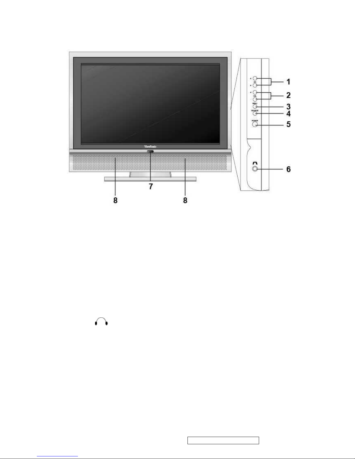
3. Front Panel Function Control Description
1. CH ▲/ ▼
Changes the channel.
2. VOL +/–
Used for changing the volume.
3. MENU
Display menu screen
4. SOURCE
Switch between display input sources.
5. POWER
Turns the TV on and off. A green light indicates that TV is on and red that it is off.
6. EARPHONE
Used for connecting headphones to the TV.
7. Power indicator LED
GREEN shall apply during all operational states (i.e. with image present), LED light off when
the product in stand-by mode. Red light apply when no PC/HDMI signals in PC/HDMI mode
after 15 sec.
8. SPEAKERS
Audio output.
ViewSonic Corporation Confidential - Do Not Copy N3260w_N3760w
N4060w
9
4. Circuit Description
Power Circuit:
Switching mode power supply provided 3 sets of Vcc power supply +5V, +12V and +24V. The
Details please refer to page 26 of schematic.
Vcc +5V : supply to Stand-By U48 chip and Main Board or Panel LVDS.
Vcc +12V : supply to Audio Processor, Audio Class-D AMP or Panel LVDS.
Vcc +24V : supply to Panel’s inverter.
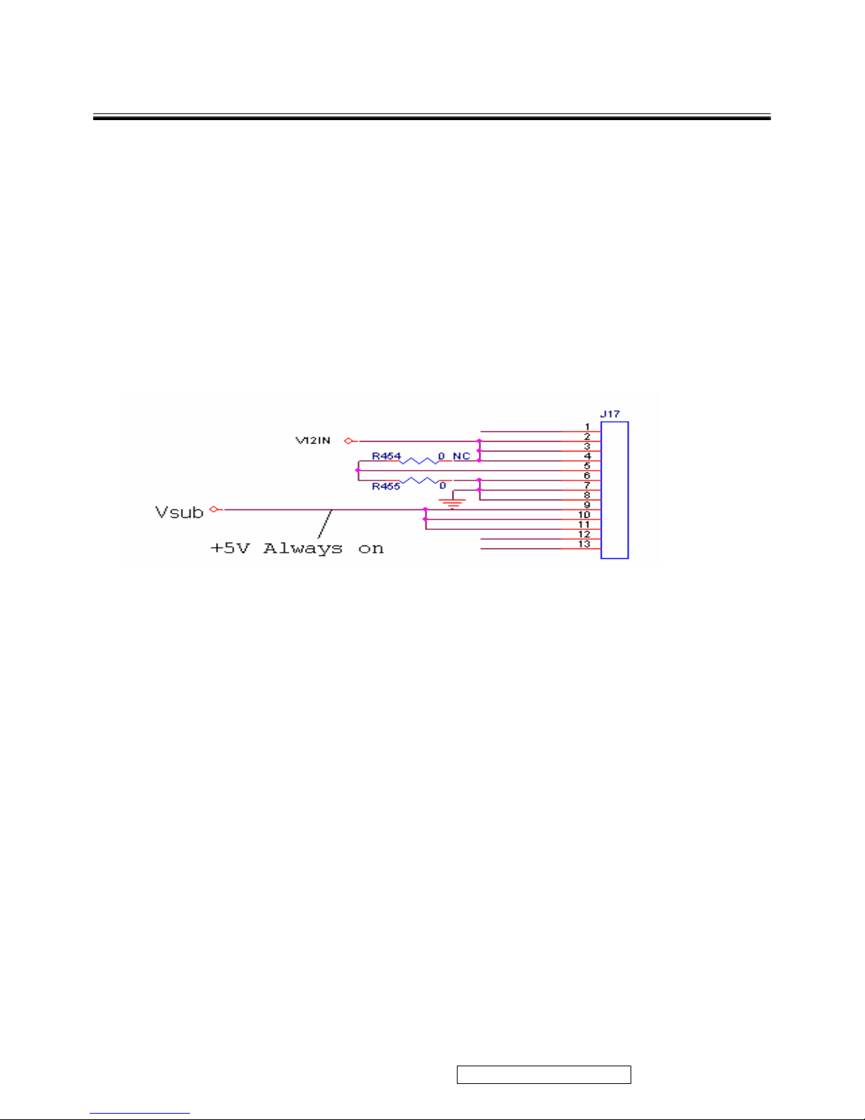
A.
Cold-Opening Mode
:
i. Switching power will produce +5V when plug in and transmit to the Vsub pin of Stand-By U48 chip
via J17.
ii. This machine is in Stand-By Mode now.
B.
Stand-By Mode(+5V)
:
i. When this machine is in Stand-By mode, only U48 SM5964C40J keep working, so the system can
assure the consumption power is < 1.0W in Stand-by Mode.
C. Power ON Mode(+5V ,+12V)
i. Receives the start order
When the system receives the start order by Power Key of the remote control (signal mark IRup)
or Power ON/OFF of the control panel(signal mark PWSW), it will process the following action.
ViewSonic Corporation Confidential - Do Not Copy N3260w_N3760w
N4060w
10
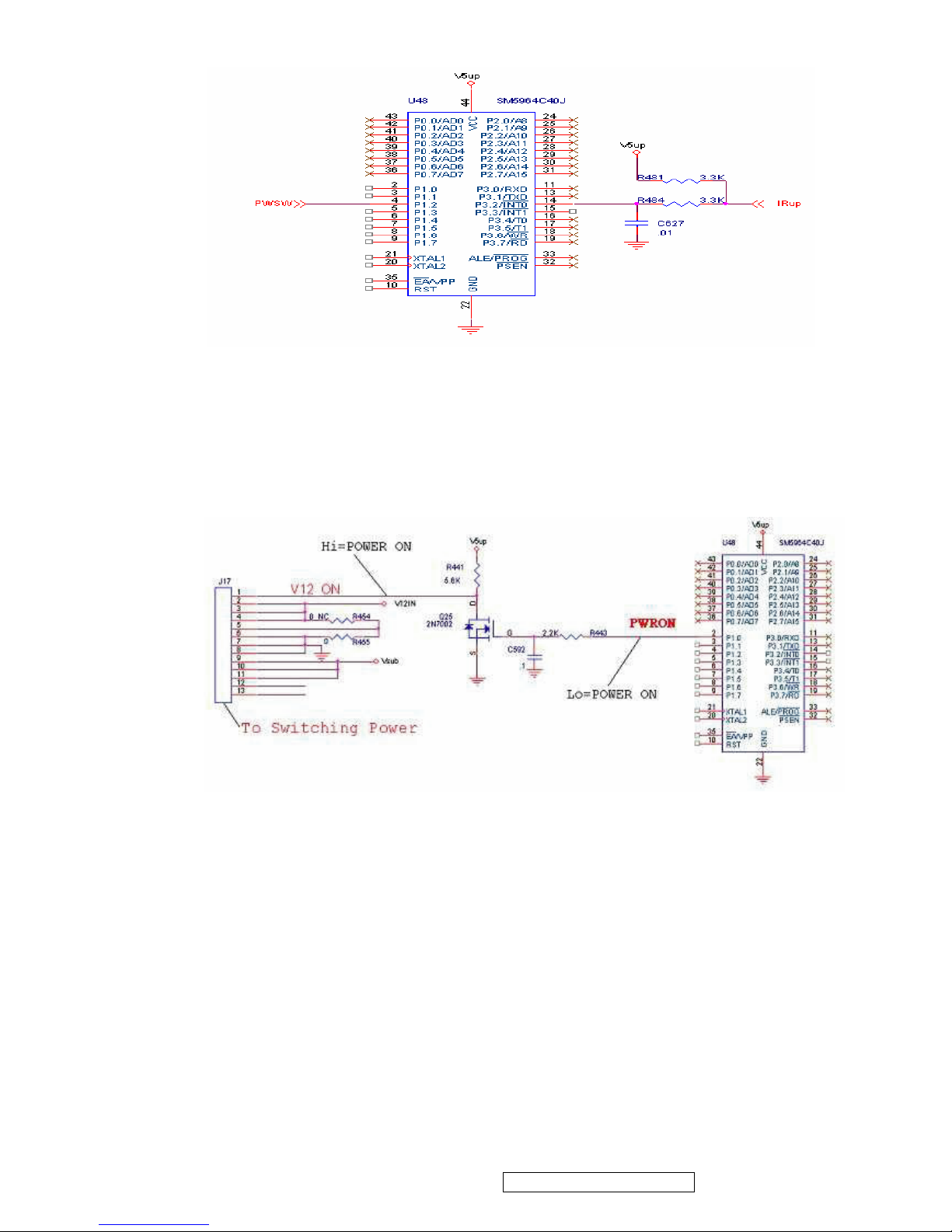
ii. Switching power ON
When Switching power receives the start order by 2
nd
pin of U48 (signal mark PWRON),
Then by Q25 2N7002 (signal mark V12_ON) and 1
st
pin of J17 to control Switching Power Model
provides +12V (POWER STREE, refer to page 26 of schematic) and +24V to turn on the circuit of
+5V(signal mark VCC).
iii. . +5V (signal mark VCC) turn on when V12_ON=Hi, Every batches of digital board circuit would be
able to process Power ON procedure. (VCC POWER STREE, please refer to page 26 of schematic)
iv. CPU RESET
U19 PW328 CPU will output a Hi level to trigger other IC to reset when +5V, +12V and +24V start to
work. Then Firmware starts to read the data of U39 and U40 via U35 PW200 CPU and transmits data
via 12C and sends control signal to run the TURN ON procedure.
ViewSonic Corporation Confidential - Do Not Copy N3260w_N3760w
N4060w
11
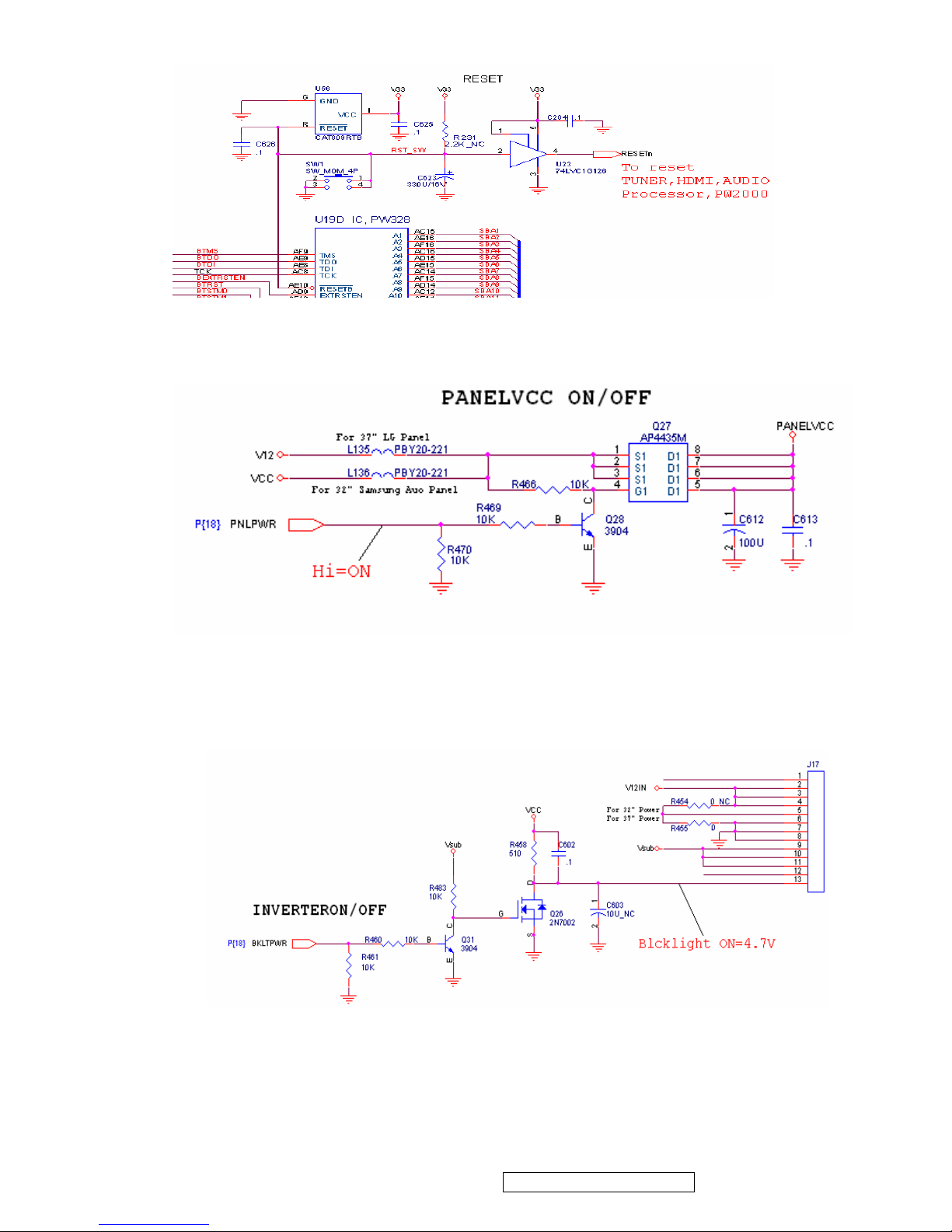
v. PANELVCC ON
In the period of POWER ON, the signal of control PANELVCC output a Hi level signal from PW2000
I/O port PNLPWR, PANELVCC will supply power to Panel via LVDS output Header J5.
vi. INVERTER ON
When POWER ON, the signal of control Backlight-ON will output from I/O port BKLTPWR of U35
PW2000 via Q31, Q26 to 13
th
pin of J17 and sends to Switching Power supply. Then Switching
Power Supply forwards the signal to the Inverter of Panel and turn it on.
vii. BACKLIGHT ADJUST
The signal of Backlight Adjust which output from PWM I/O port of U19 PW328 sending a PWM
signal to U57 C621 converged into a DC signal then forward to Inverter of Panel via 12
th
pin of J17
to adjust the brightness of Backlight.
ViewSonic Corporation Confidential - Do Not Copy N3260w_N3760w
N4060w
12
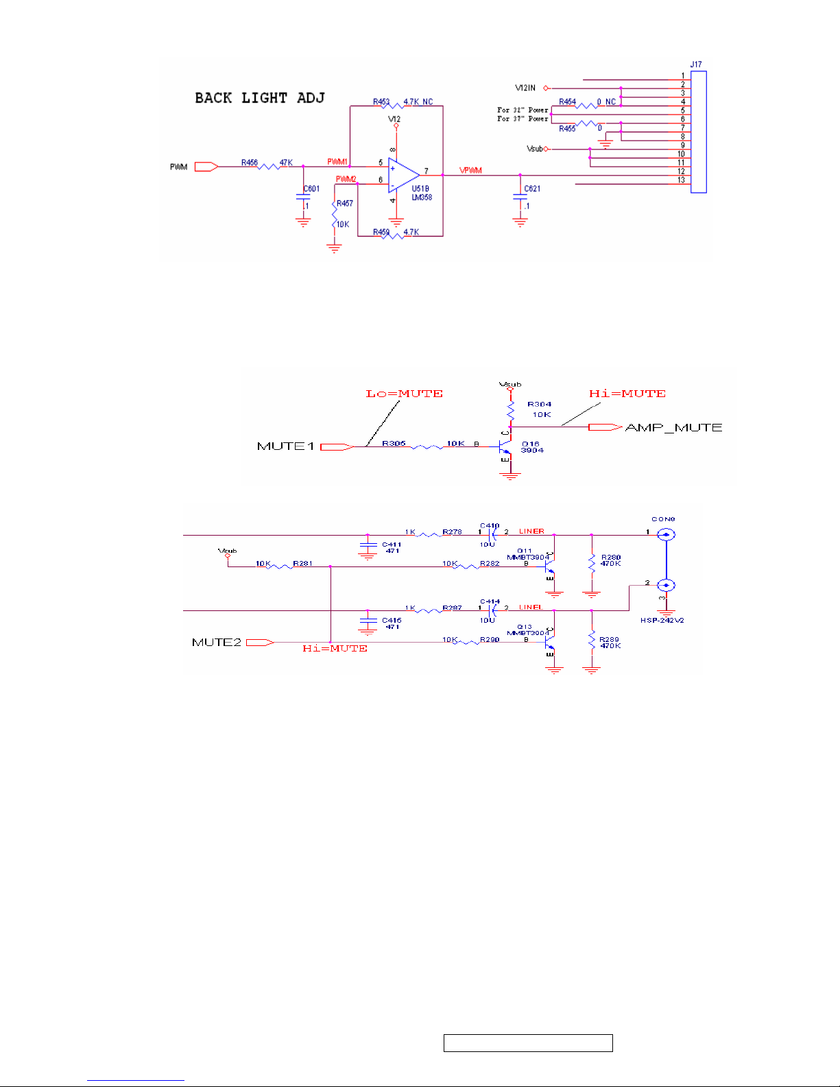
viii. AUDIO AMP MUTE ON/OFF
The control signal of AMP MUT was outputed from MUTE1 and MUTE2 I/O port of PW2000. MUTE2 will
control the RC JACK Audio Output Mute. (For preventing from abnormal sound occurred when turn on TV
set, Audio Amp Mute will act in first and last procedure)
ix.
x. THE THREE BIRDS LOGO
The ViewSonic Logo will show up in 5 seconds after program execution, then disappeared. All the
POWER ON procedure will be finished when AMP Relay sound be heard and screen displayed.
D.
POWER OFF Mode
:
i. After POWER ON procedure finished, the signal of Keypad and remote control will transform to
PW2000 for further processing. U48 chip did not handle the signal of Keypad and remote control
any more. When the system receives the power off order by Power Key of remote control or Power
ON/OFF of the keypad. Firstly PW2000 will send current screen status to memory U38 via I2C bus,
then the PWRDOWN I/O port of PW2000 will send a Hi signal to U48 closing the Switching
power.
ViewSonic Corporation Confidential - Do Not Copy N3260w_N3760w
N4060w
13
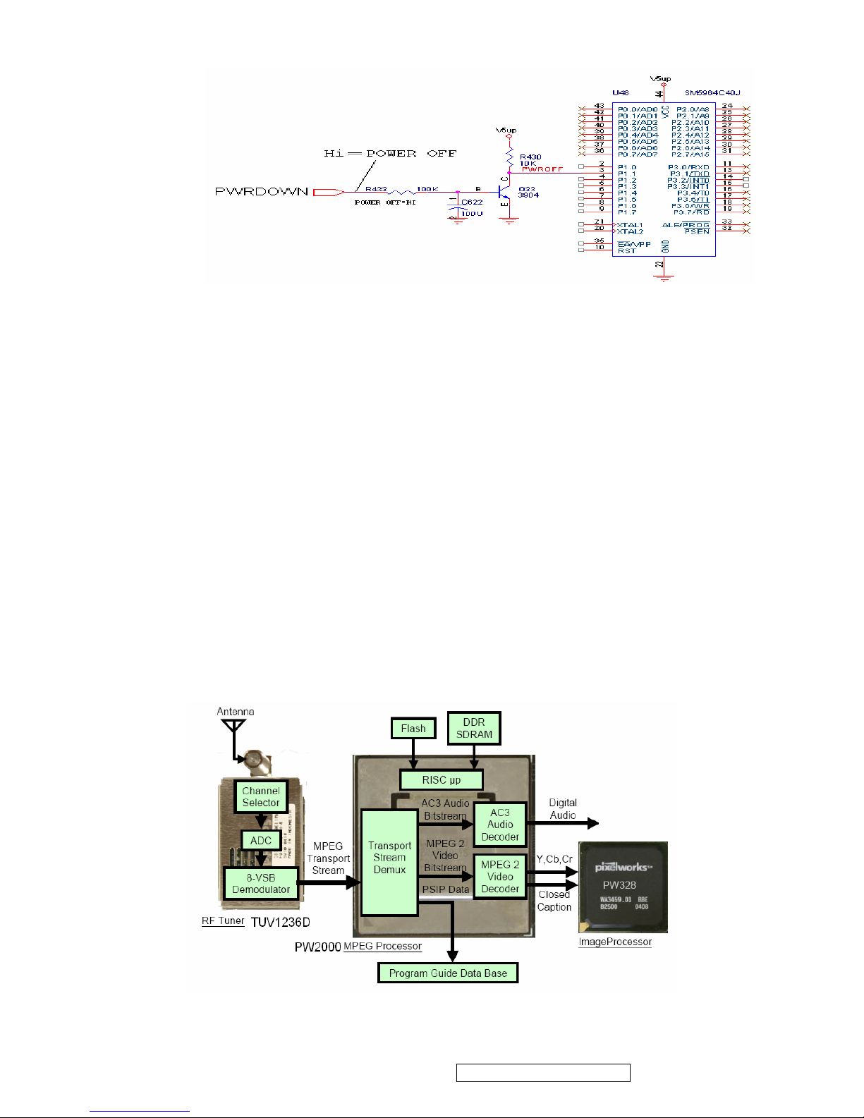
Antenna Circuit:
Tuner (TUV1236D) has two RF inputs. Upwards was the connector of Terrestrial Input, Downwards was the
connector of CATV Input.
A.
Terrestrial Input Connector
:
Connects to your ATSC antenna and receives broadcasting signals. There are two signals, Analog TV
(NTSC signal) and Digital TV (ATSC signal) could be received.
z Analog TV(NTSC signal)
Tuner TUV1236D receive the signal come from RF NTSC signal,Selects desired channel and
demodulate image composite signal (signal mark T1CVBS) by pin 14 of Tuner output to U19 PW328
decoder via path C224 and audio SIF signal (signal mark T1SND) by pin15 of Tuner output to U29
MSP4450G via C396 for demodulating MTS/SAP of Digital TV signal (ATSC signal).
z Digital TV (ATSC signal)
Tuner TUV1236D receive the signal come from ATSC signal,Selects desired channel and converts
analog signal into MPEG Transport Stream via Tuner TS1( Transport stream TS1DATA0-TS1DATA7)
bus into U35 PW2000 to separates MPEG video and AC3 digital audio.
ViewSonic Corporation Confidential - Do Not Copy N3260w_N3760w
N4060w
14
B.
CATV Input Connector
:
Connecting to your coaxial cable from local TV station.
z Tuner TUV1236D receive the signal come from CATV signal,Selects desired channel and
demodulate image composite signal (signal mark T1CVBS) by pin 14 of Tuner output to U19 PW328
VDC decoder via C224 and audio SIF signal (signal mark T1SND) by pin 15 of Tuner output to U29
MSP4450G via C396 for demodulating MTS/SAP.
MPEG Processor PW2000:
When MPEG Transport Stream data input U35 PW2000 internal decoder Separates MPEG video and
AC3 digital audio .The digital video output from PW2000 Digital Video Signal Output port (44 Pins) to U19
PW328 digital input port(port 1) . The digital audio output via I2S bus (MPEG_CL, MPEG_WS, I2S_DI1)
to the externally connected DA converter( U29 MSP4450G). Each of these functions was described in
more detail in the sections that follow.
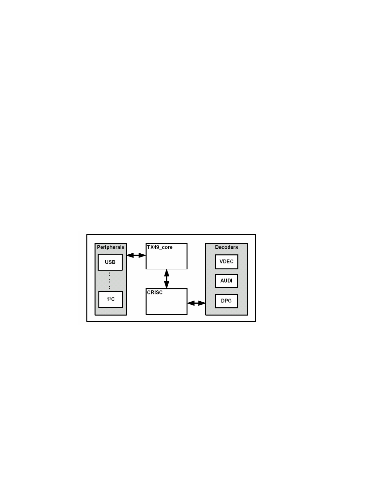
z System Control
The PWM2000 incorporates a TX49 core core ( 64-bit MCU core ) and a CRISC (Control 32-bit RISC
processor ) for system control. The TX49 core issues instructions to the CRISC as well as to the
peripheral controllers such as PCIC (
PCI Controller) , USB, and UART. Based on the instructions sent
from the TX49 core, the CRISC controls decoders such as video (VDEC), and audio (AUDIO),
System Control Detail Block Diagram
z United Memory
DDR SDRAM ( U42,U43,U44,U45 ) is externally connected to the PWM2000. In addition to the
CRISC and TX49 core, the unified memory allows all internal decoders can share data via VMMS
(
Virtual Multi-port Memory System ,Controls external DDR-SDRAM 64 bits) , which reduces external memory
types and capacities.
ViewSonic Corporation Confidential - Do Not Copy N3260w_N3760w
N4060w
15
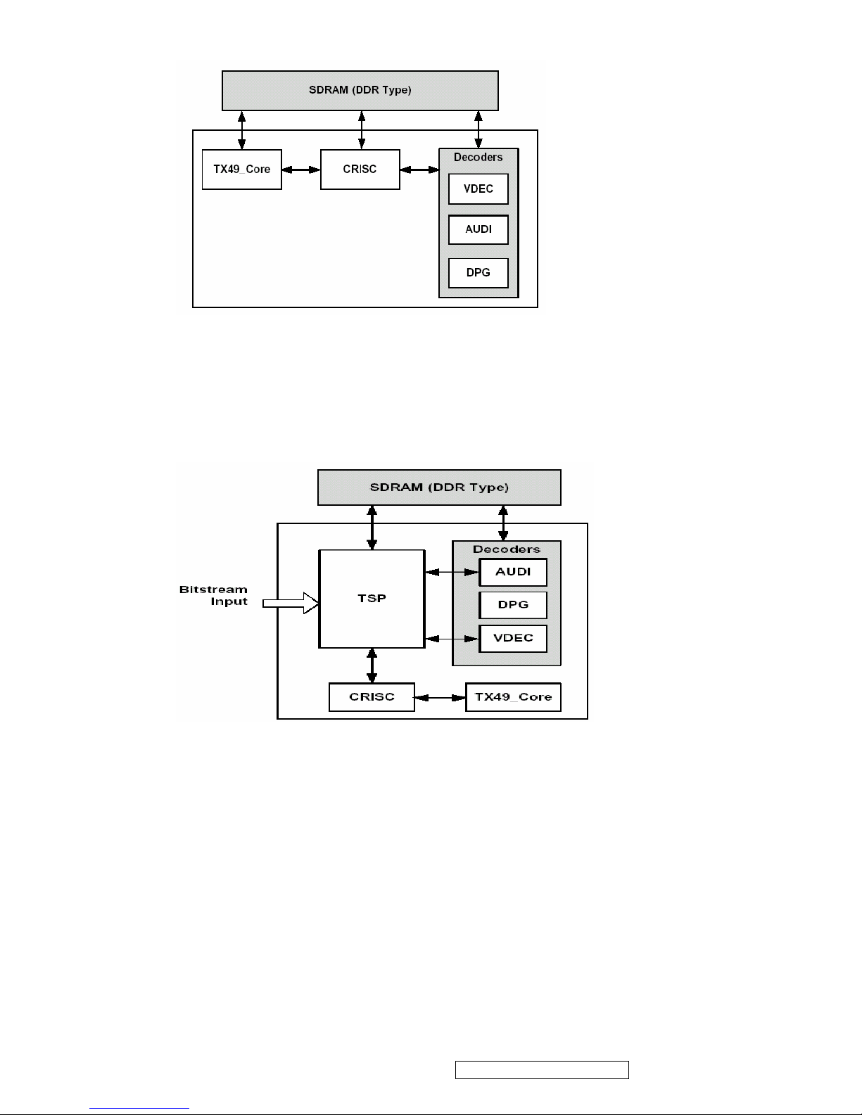
Unified Memory Block Diagram
z Stream Decoder
With the built-in Transport Stream Demultiplexing Processor (TSP), the PWM2000 supports bitstream
input in TS format. The TSP can separate the TS into audio and video PES, analyzing the PES
header, and transferring the PES to the audio and video decoders. The TSP can also transfer any
data from the input stream to external memory.
Stream Decode Block Diagram
z Video/Audio Signal Output and External Signal Mixing
Video data decoded by the VDEC (Video Decoder ) is graphically processed (overlaid) by the DPG
(
Display Picture Generator ). Digital video signals are directly output from the DPG.
The audio signals decoded by the AUDIO are output as digital data to the externally connected DA
converter. The digital data output is also compatible with the SPDIF format output.
The PWM2000 can externally input both audio and video digital data. The PWM2000 has a function
which mixes the input data internally then outputs them.
ViewSonic Corporation Confidential - Do Not Copy N3260w_N3760w
N4060w
16
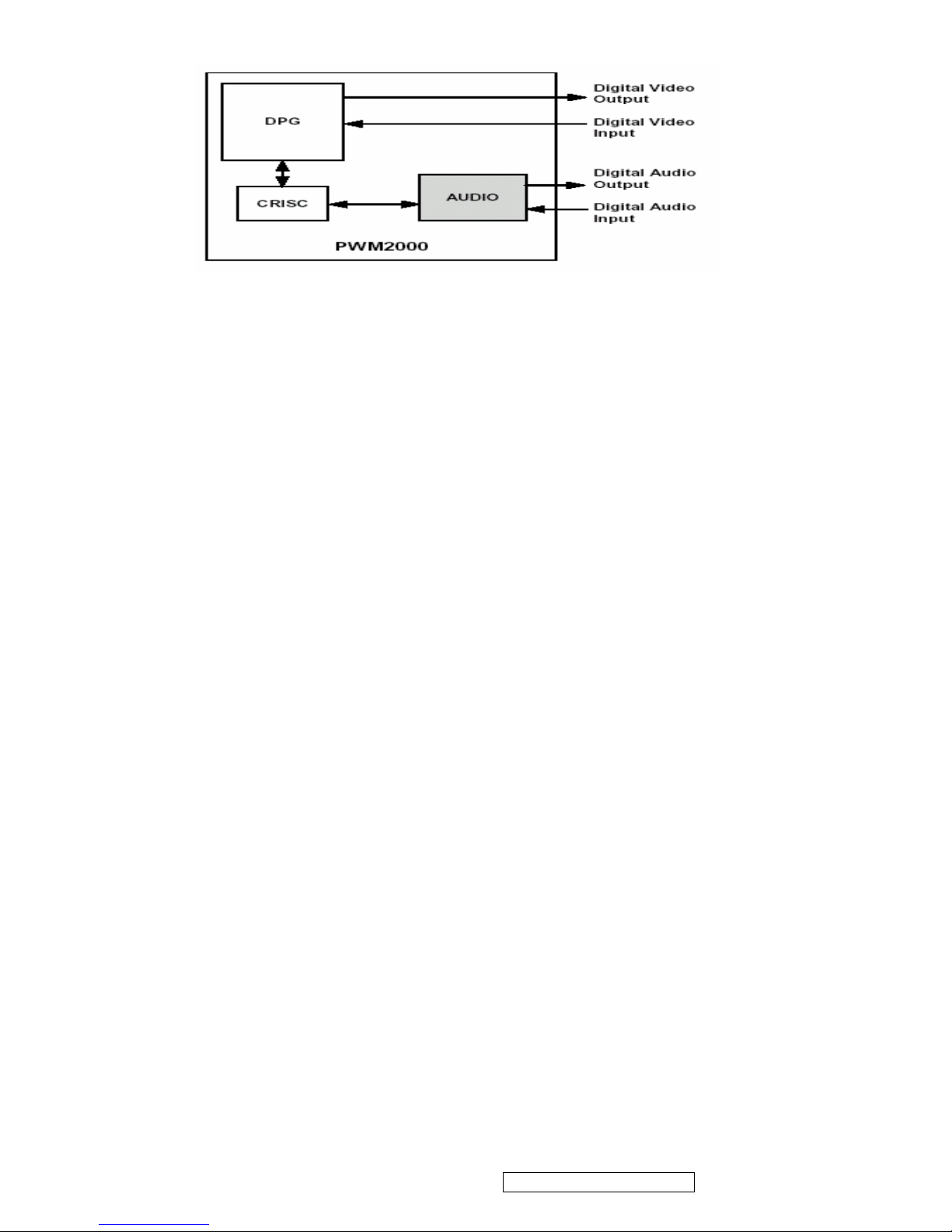
Video/Audio Signal Output Block Diagram
z Firmware
The CRISC/TSP/VDEC/DPG/AUDIO blocks of the PWM2000 are operated by firmware (U30,U40). A
structure supporting firmware enables the PWM2000 to implement a flexible system configuration.
AV Input circuit (AV,S,YPbPr,PC,HDMI ):
AV Input source include AV1(S1),AV2(S2),HD1,HD2,PC,HDMI.
z AV1 and AV2 Input
AV1 and AV2 include AV jack and S-video jack.
S jack has priority when S-jack and Video-jack plug in at the same time.
SDET-1 and SDET-2 =HI When S-jack plug in.
Composite video(AV1CVBS ,AV2CVB S)and Y(AV1LUMA ,AV2LUM A)/C(AV1CHROMA,
AV2CHROMA) signal input Analog input port of U19 PW328.
AV1,AV2 Audio R/L Signals input U29 MSP4450G.
z HD1 and HD2 Input
Component signal includes Y,Pb,Pr
HD1(Component Video signal AV3Y, AV3PB, AV3PR) and HD2(Component Video signal AV4Y,
AV4PB, AV4PR) signal input Analog input port of U19 PW328.
HD1 and HD2 Audio R/L Signals input U29 MSP4450G.
z PC INPUT
PC(VGA)signal includes :R、G、B、HS、(Horizontal Sync Signal)、VS(Vertical Sync Signal)
When power on, PC will read the data of U19 via I2C then transfer R, G, B, HS and Vs signals into
analog input port of U19 PW328 via VGA Pin.
PC Audio R/L Signals input U29 MSP4450G.
z HDMI INPUT
The HDMI cable and connectors carry four differential pairs that make up the TMDS data and clock
channels. These channels are used to carry video, audio and auxiliary data. In addition, HDMI carries
a VESA DDC channel. The DDC is used for configuration and status exchange between a single
Source and a single Sink(U13 SiI 9011 and U6 EDID PROM).
The U13 SiI 9011 video output goes to U19 PW328 digital input port(port 0).
The digital audio output by I2S bus (HDMI_CL, HDMI_WS, I2S_DI2) to the externally connected DA
ViewSonic Corporation Confidential - Do Not Copy N3260w_N3760w
N4060w
17

converter( U29 MSP4450G)
VIDEO Input circuit (AV,S,YPbPr,PC,HDMI )
AUDIO Input circuit (TV,AV,S,YPbPr,PC,HDMI )
ViewSonic Corporation Confidential - Do Not Copy N3260w_N3760w
N4060w
18

5. Adjusting Procedure (Service mode)
An internal settings service menu is provided to allow adjustment of the device by qualified service personal.
Improper use of the internal settings service menu may render the device unusable. Refer to the following sections
to learn how to operate the service menu.
Starting the service mode
To start the service mode of operation and view the internal settings menu, do the following:
1. Switch on the LCD TV and make sure that the TV mode is selected.
2. Press 991 on the remote control to enter the internal Service menu.
3. Press MENU to switch the service mode pages.
4. Press ▲ and ▼ to scroll through the various menu options.
5. Press ◄ and ► to change the menu settings.
6. Press WIDE to save the new settings and exit.
z TV/AV/S-Video WHITE BALANCE, BRIGHTNESS, CONTRAST ADJUSTMENT (ADJUSTING UNDER AVI
SOURCE)
--WHITE BALANCE ADJUSTMENT--
1. Press 991 on the remote control to enter the internal Service menu.
2. Press MENU to switch to the PW328 Scaler Menu page
3. Press ▲ and ▼ to scroll to Page 2-3 options
4. Press ◄ and ► to adjust the Offset Red, Offset Blue, Gain Red, Gain Blue menu settings.
5. Press WIDE to save the new settings and exit.
(Please don’t adjust others setting in page 2-3)
--BRIGHTNESS ADJUSTMENT—
1. Press 991 on the remote control to enter the internal Service menu.
2. Press MENU to switch to the PW328 Scaler Menu page
3. Press ▲ and ▼ to scroll to PW328 FE VDC Menu Page 2-1 options
4. Press ◄ and ► to adjust the Brightness setting.
5. Press ▲ and ▼ to scroll to TV/AV/S Parameter=AV1 setting and press ► to run the setting. (This
procedure will copy the settings of AV1 to AV2 & TV)
6. Press WIDE to save the new settings and exit.
z ATSC DTV WHITE BALANCE/BRIGHTNESS/CONTRAST ADJUSTMENT (ADJUSTING UNDER THE AIR
MODE AND W ITH ATSC SIGNAL)
1. Repeat the above mentioned step 1 to 2
2. Press ▲ and ▼ to scroll to PW328 Scaler Menu Page 2-3 options
3. Press ◄ and ► to adjust the Offset Red, Offset Blue, Gain Red, Gain Blue menu settings
4. Press WIDE to save the new settings and exit.
(Please don’t adjust others settings in page 2-3)
z YCbCr & YpbPr of COMPONENT 1, 2 WHITE BALANCE/BRIGHTNESS/CONTRAST ADJUSTMENT
ViewSonic Corporation Confidential - Do Not Copy N3260w_N3760w
N4060w
19
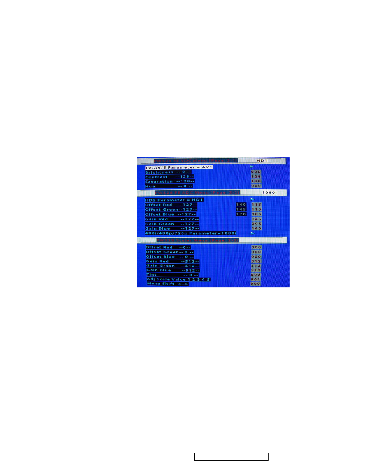
Step 1: Getting COMPONENT 1 connect to 1080i signal. (The settings could not be saved if signals input from
COMPONENT 2 or connect to other sources such as 720P, 480P, 480i…..,etc.)
Step 2: WHITE BALANCE ADJUSTMENT OF Component—
1. Repeat the above mentioned step 1 to 2
2. Press ▲ and ▼ to scroll to PE328 FE ADC page 2-2 options
3. Press ◄ and ► to adjust the Offset Red and Off Blue settings.
4. Press ◄ and ► to adjust the Offset Green setting. ( Brightness Adjustment)
5. Press ◄ and ► to adjust the Gain Green setting. (Contrast Adjustment)
6. Press ▲ and ▼ to scroll to 480i/480P/720P Parameter=1080i setting and press ► to run the setting.
(This procedure will copy the setting of 1080i to 480i/480P/720P)
7. Press ▲ and ▼ to scroll to HD2 Parameter=HD1 and press ► to run the setting. (This procedure will
copy the setting of HD1 to HD2)
8. Press WIDE to save the new settings and exit.
z WHITE BALANCE ADJUSTMENT OF PC INPUT
1. Connecting to VGA Timing mode
2. Under service mode, Press ▲ and ▼ to scroll to PE328 FE ADC page 2-2 options
3. Press ◄ and ► to adjust the Offset Red, Offset Green and Off Blue settings.
4. Press ◄ and ► to adjust the Gain Red and Gain Blue settings.
5. Press WIDE to save the new settings and exit.
OPERATION OF RS232 WRITING
(1) RS-232 mounted on the Main Board was the main interface writing new firmware. You can update new
firmware to U39 by RS232.
(2) Writing firmware need following equipment:
1. RS232 interface built in PC.
2. RS232 cable
3. Pixelworks Flash Upgrader software
ViewSonic Corporation Confidential - Do Not Copy N3260w_N3760w
N4060w
20
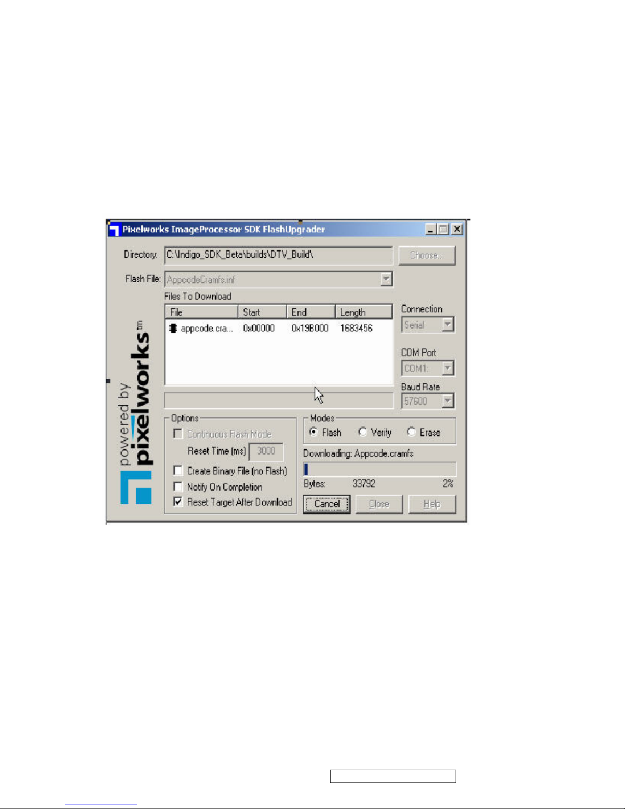
(3) Connecting method: connecting RS232 interfaces between PC and TV set.
Firmware writing procedure:
1. Execute Pixelworks Flash Upgrader software
2. Select Baud Rate by 57600
3. Download “appcode.crams” file.
4. Choose “Flash” mode entering standby status for writing firmware
5. Turn on TV set.
6. "Bytes Bar" will showed on the screen in few seconds indicating firmware was downloading.
7. The download process will take about 4 Minutes. It won’t change the original code when download
process intercepted. Once download process was finished system have to take at least 30 seconds
updating new firmware. Please make sure power was supplied without interruption; otherwise system will
shut down.
8. System will restart automatically after finishing writing process.
ViewSonic Corporation Confidential - Do Not Copy N3260w_N3760w
N4060w
21

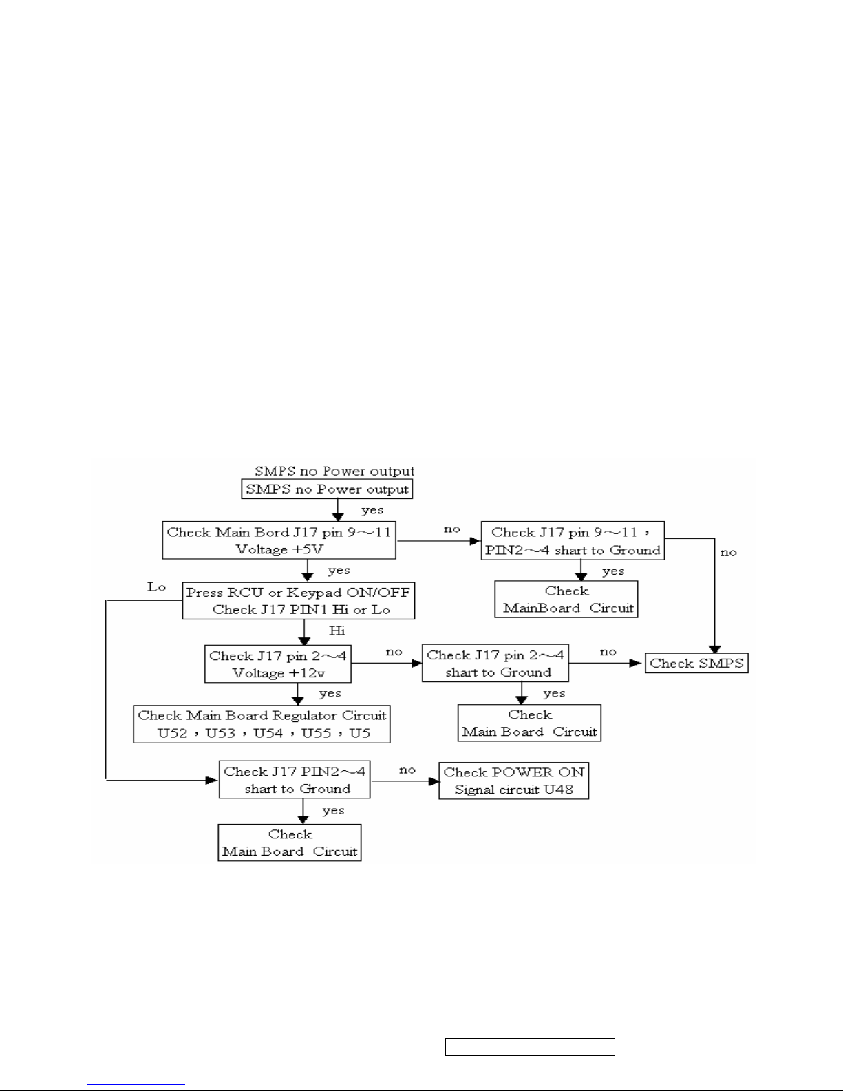
6. Trouble Shooting Flow Chart
No power
z Make sure the LCD is properly connected.
z Make sure the AC power cord is properly connected.
z Make sure the AC power is ON, DC power button is ON (Green LED).
z
Plug another electrical device (like a radio) to the power outlet to verify that the outlet is
supplying the proper voltage.(see figure 1)
Poor or no picture
z The TV station may be experiencing problems. Try another channel.
z The Cable TV signal may be scrambled or encoded. Please contact your local cable
operator.
z Make sure that connection to other components are correct.
z Make sure that setup has been done correctly after connections.
z Make sure the correct input is selected and the input signal is compatible. (see figure 2)
Strange color, light color, or color misalignment
z Ensure that the video cable is securely connected.
z The picture may appear dim in a brightly lit room.
z Adjust brightness and contrast.
z Check the input signal setting.
No sound
z Check your audio connections
z The MUTE button may have been pressed, try pressing this button again.
z Check your audio settings, your TV audio may be set to minimum.
z Press the Volume + (Up) button on the remote control. (see figure 3)
Remote control unit does not operate
z Make sure batteries are inserted correctly.
z Batteries could be weak or dead. Replace batteries.
z Is a fluorescent light illuminated near the remote control sensor?
z The path of the remote control beam may be blocked. Make sure the path is clear and that
the remote control is aimed at the remote control sensor on the TV.
z Press only one button at a time and it is the correct one for the operation you want to
perform.
Unit cannot be operated
z External influences such as lightning or static electricity may cause improper operation. In
this case, operate the unit after first turning on the power of the LCD and the AVC System,
or unplug the AC cord for 1 to 2 minutes, then replug again.
Power is cut off suddenly
z Is the sleep timer set?
ViewSonic Corporation Confidential - Do Not Copy N3260w_N3760w
N4060w
22
z The internal temperature of the unit has increased. Remove any objects blocking the vent
or clean as necessary.
No CATV or AIR reception
z Is the AIR/CABLE option set correctly? Please set the AIR/CABLE option to CABLE.
z AIR/CATV is connected improperly or not connected; please check all the AIR/CATV
connections.
z The cable TV service is interrupted; please contact your cable operator.
z Connects to your ATSC antenna or coaxial cable from a local TV
Picture is cut off/with sidebar screen
z Is the image positioned correctly?
z Are screen mode adjustments such as picture size set correctly?
Figure 1 SMPS no power output
ViewSonic Corporation Confidential - Do Not Copy N3260w_N3760w
N4060w
23
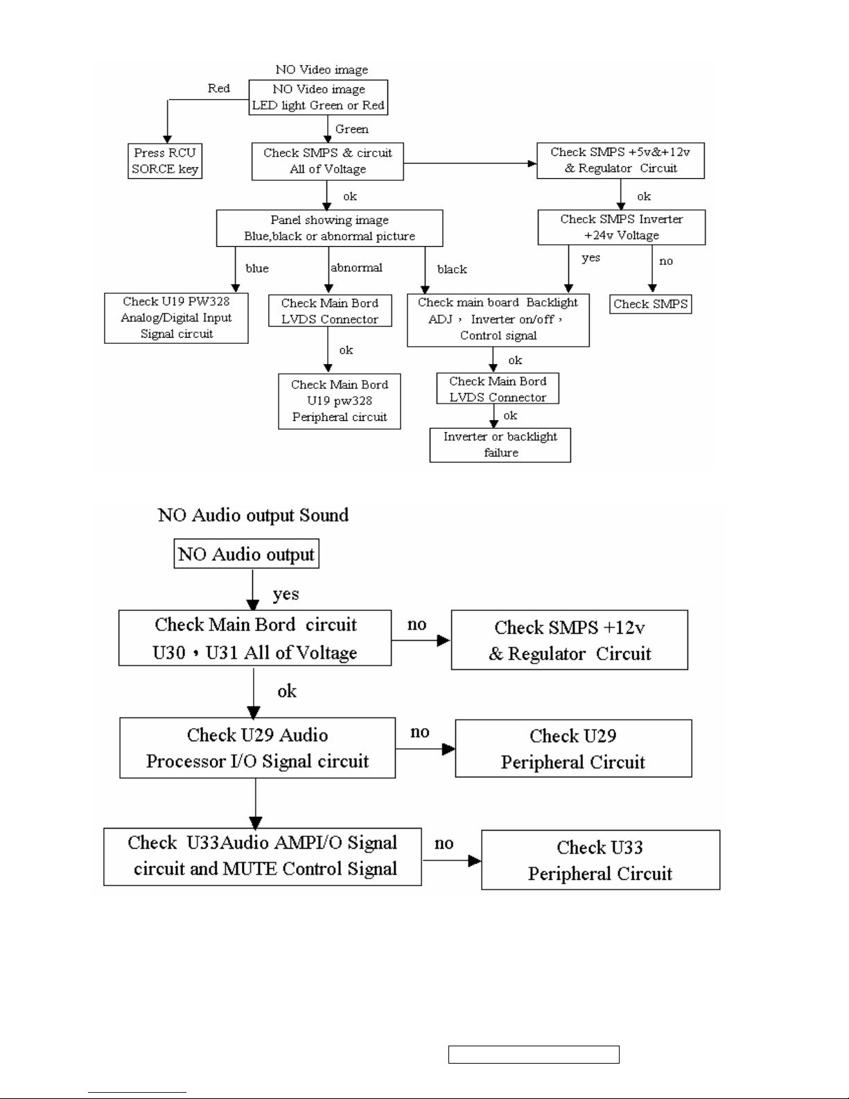
Figure 2 . NO Video image
Figure 3 . NO Audio output Sound
ViewSonic Corporation Confidential - Do Not Copy N3260w_N3760w
N4060w
24
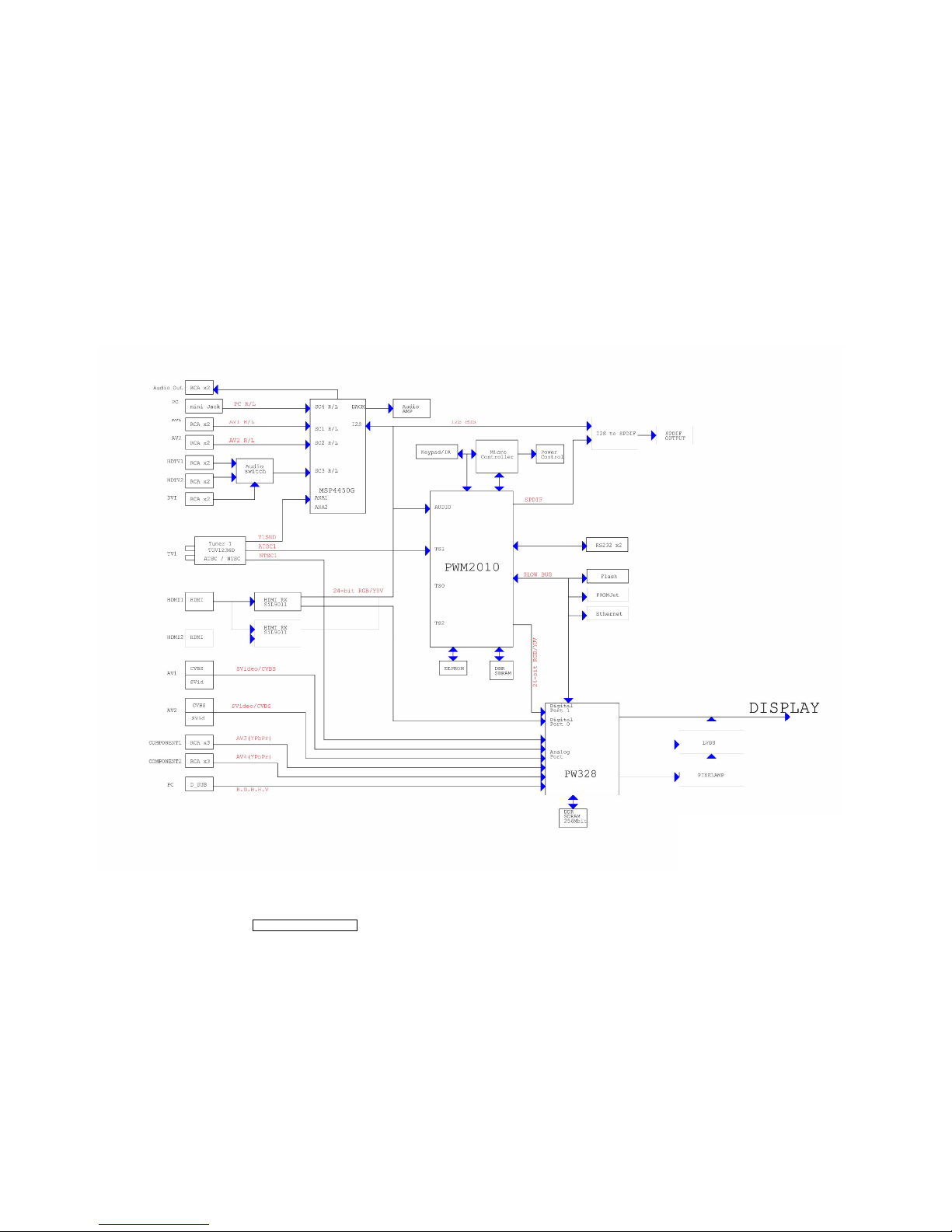
7. Block Diagram
N3260w / N3760w / N4060w
ViewSonic Corporation Confidential - Do Not Copy N3260w_N3760w
N4060w
25
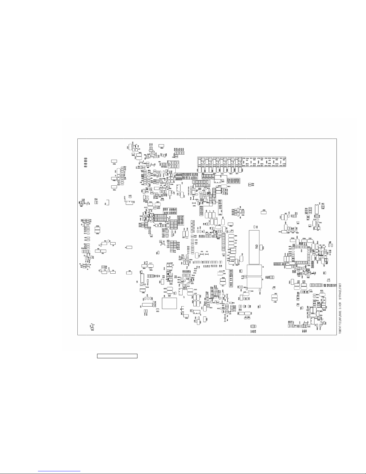
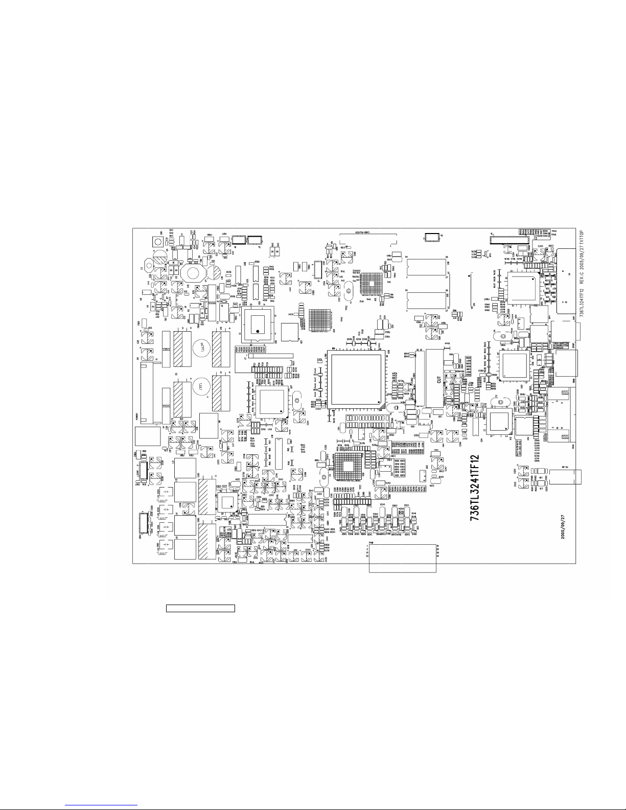
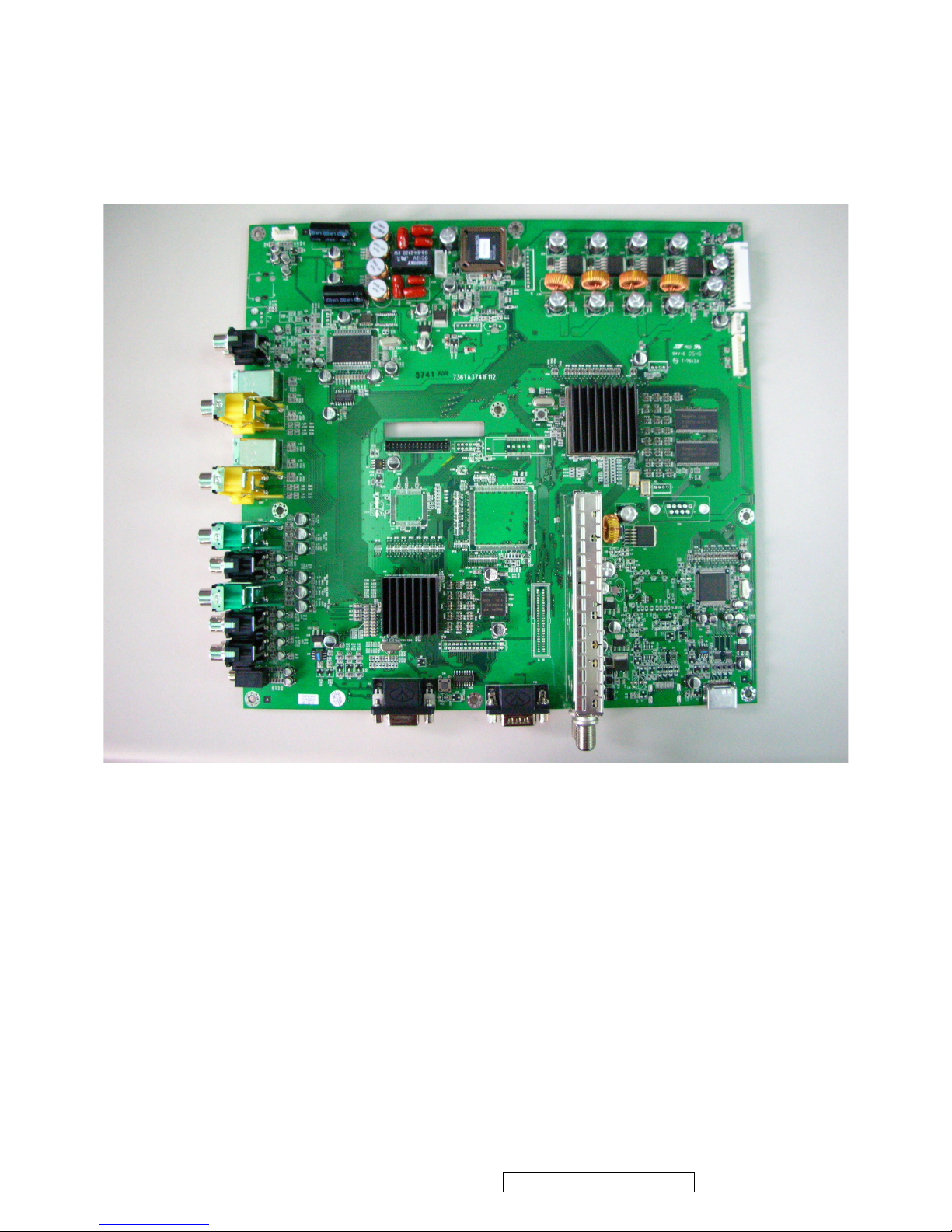
8. PCB Layout Diagrams
ViewSonic Corporation Confidential - Do Not Copy N3260w_N3760w
N4060w
26
ViewSonic Corporation Confidential - Do Not Copy N3260w_N3760w
N4060w
27

ViewSonic Corporation Confidential - Do Not Copy N3260w_N3760w
N4060w
28
ViewSonic Corporation Confidential - Do Not Copy N3260w_N3760w
N4060w
29
 Loading...