

Page 1

Service Manual
ViewSonic N1700W
WIDE LCD MONITOR
ViewSonic
381 Brea Canyon Road, Walnut, California 91789 USA - (800) 888-8583
Page 2

TABLE OF CONTENTS
1. Feature 1
2. Brand new Specification 8
3. Compatibility 10
4. Block Diagram 14
5. PCBAs Connector Pin Assignment 23
6. IC Descriptions 30
7. Wave Form 36
8. Trouble Shooting Guide 45
9. Replacement Part List 48
10. Complete PCBAs Part List 56
11. Disassembly Procedure 70
12. Alignment Procedure 75
13. EDID Programming Procedure 79
14. Testing Procedure 83
15. OSD Firmware Procedure 86
16. Exploded Overview 87
17. Schematic Diagram 88
18. Appendix 90
ViewSonic Corporation
!
!
Confidential –DoNotCopy
Page 3

FCC Statement
This equipment has been tested and found to comply with limits of class B digital device, pursuant to part 15 of
the FCC rules. These limitations are designed to provide reasonable protection against harmful interference in a
residential installation. This equipment generates, uses and can radiate radio frequency energy, and for if not
installed and used in accordance with the instructions, may cause harmful interference to radio communication.
However, there is no guarantee that the interference will not occur in a particular installation. If this equipment
does cause unacceptable interference to radio or TV reception, which can be determined by turning the
equipment off and on the user is encouraged to try to correct the interference by one or more of following
measures:
1. Reorient or relocate the receiving antenna
2. Increase the separation between equipment and receiver
3. Connect the into an outlet on circuit different from that to which the receiver is connected
4. Consult the dealer or an experience radio/TV technician for help
FCC Warning
To assure continued FCC compliance, the user must has a ground power supply cord and provide shielded video
interface cable with bonded ferrite cores. Also, unauthorized changes or modifications to VisionBank products will
void the user’s authority to operate this device
Thus VisionBank will not be held responsible for the product and its safety
CE Certification
Caution
Use a power cable that is properly grounded. always use the AC Cords listed below for each area:
USA……………………….. (UL)
Canada…………………… (CSA)
Germany…………………. (VDE)
In other areas, use AV cord which meets the local safety standards
This device complies with the requirements of the ECC directive 89/3366
EEC with regard to “Electromagnetic compatibility.”
ViewSonic Corporation
!
!
Confidential –DoNotCopy
Page 4
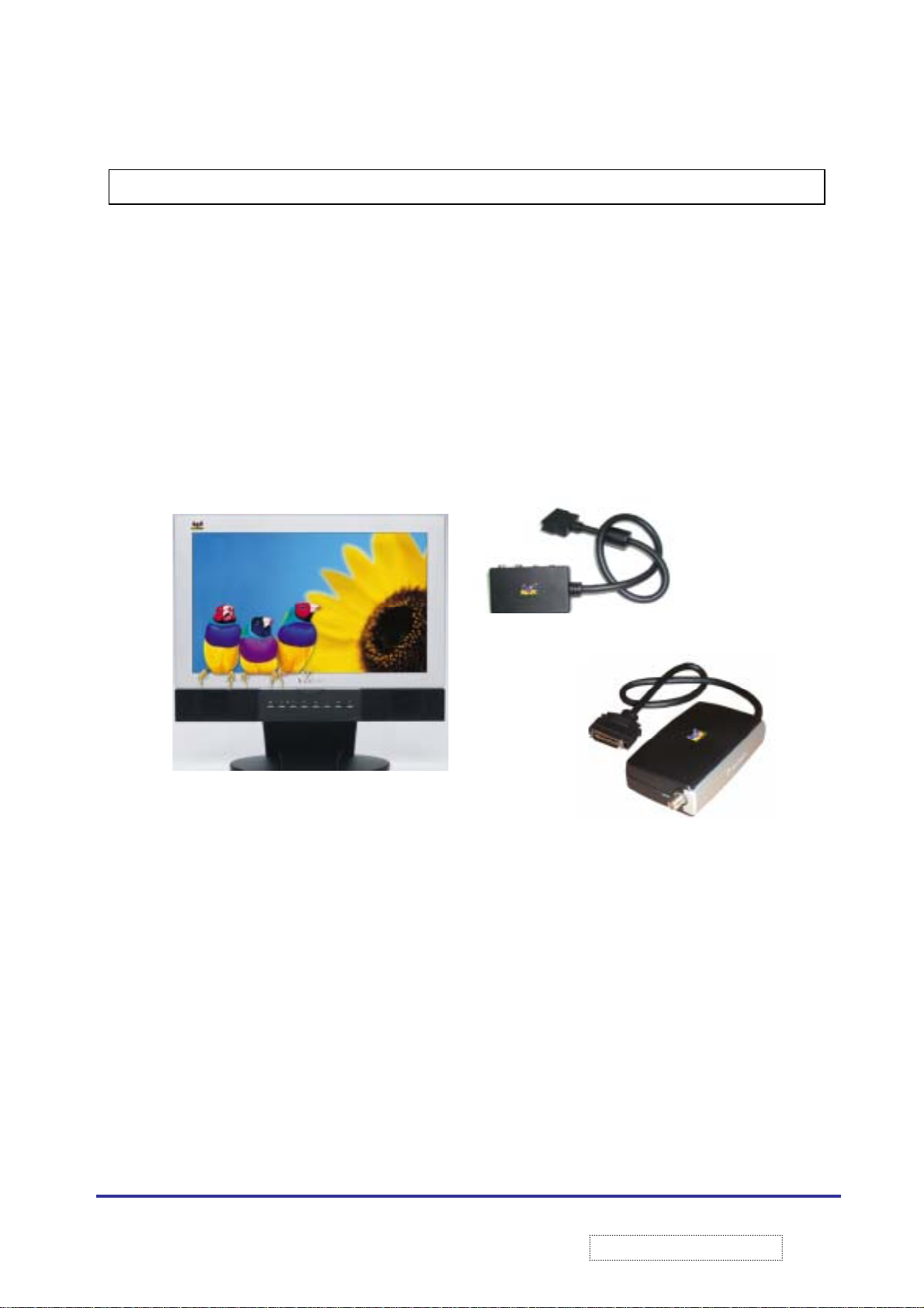
1. Feature
N1700w is a 16:9 HDTV ready LCD Monitor and optimized for Data and in Video modes. In addition, all
Audio and Video inputs will be consolidate via a VXP connector. All design aspects of the N1700w is
compatible with optional ‘expansion’ boxes that connect to the “VXP” connector, which include:
a. VXP 10: External Box that allows RCA composite, SVHS, and Y P
b. VXP 25: External Box that gives VXP 10 Functionality + Analog TV Tuner.(Except SVHS)
Connections
b Pr
(a.)
(b.)
1
ViewSonic Corporation
!
!
Confidential –DoNotCopy
Page 5

2. Brand New Specification
2.1 Display Specification
Characteristic Description
LCD Panel Size Fujitsu FLC43XWC6V-02T
LCD Type TFT Active Matrix Wide Color
LCD Interface TTL.
Signal Input Video: RGB analog;
Sync: H.V separate Sync
Horizontal: 1024 (typ)
Vertical: 768 (typ)
Connector Analog: 15 pin Mini D-SUB.
DVI: 1.8m,Black with Blue
VXP:36 pin right angle.
Resolution (Native) 1280*768
Display Area 369.6*221.76 mm (H*V)
Aspect Ratio 16:9
Brightness 340 cd/m²(min) ~ 400 cd/m²(Typical)
Brightness Uniformity 70% (min)
(9 point Mm/Max*100%)
Chromaticity (Prior to electronic correction) Wx = 0.296 +/- 0.030
(Default Setting) Wy = 0.306 +/- 0.030
Color 262,244(6 bits)
Viewing Angle H: 160 Degrees (80+80)min
V: 160 Degrees (80+80)min
Gray Scale 64
Response Time 15ms (Tr+Ton) @ 25C Typical
2
ViewSonic Corporation
!
!
Confidential –DoNotCopy
Page 6

30ms (Tr+Ton) @ 25C Max
2.2 Audio Specification
Characteristic Description
Speakers 4 Ohm x 2
Max Power Output 10W
Frequency Response 70Hz~20kHz
Distortion 1% @ 1kHz
Line Input Signal 1.0 Vrms
Line Input Impedance 10 k Ohm
Amplifier 2x10W Digital Amplifier
2.3 Power Specification
Power Supply Delta ADP-100EB
Power Input Voltage Range 90 to 264 VAC
Power Max Input AC Current 1.6A@90VAC, 1A @ 180VAC
Input Frequency Range 47 to 63.0 Hz
Output Voltage @0-8.33A load 12V
Short Circuit Protection Output can be shorted without damage
Over Current Protection 10.5A (max)
Leakage Current 3.5mA(max)@254VAC/60HZ
Power Dissipation Capability 100W (typ)
Power Saving Mode <3.5 W When output is no load @ 240 VAC
3
ViewSonic Corporation
!
!
Confidential –DoNotCopy
Page 7

Surge Immunity (No Damage) 1KV/1.2 * 50 us (IEC 1000-4-5)
2KV/1.2 * 50 us (IEC 1000-4-5)
ESD Discharge Immunity (No Damage) +/-15KV (Air Discharge)
+/-8KV (Contrast Discharge)
EMI/RFI FCC-B, CISPR 22-B
2.4 Mechanical Specification
Width 431mm
Height 414mm
Depth 172mm
Depth (Excluding stand) 60mm
Monitor Weight (Net) 5.6KG
2.5 Environment Specification
Humidity (Storage) 5% ~ 95 %
Humidity (Operating) 8%~90%
Temp (Operating) 5 ~ 40°C
Temp (Storage) -20 ~ +65°C
2.6 Packing Specification
Packing Dimension 553*250*516mm (W*D*H)
Gross Weight 10.0 kg (22.0 Lb)
Net Weight 5.6kg (12.3 Lb)
Shipping Carton Type One Piece Construction
4
ViewSonic Corporation
!
!
Confidential –DoNotCopy
Page 8

# of Units per Pallet 32
# of Units per Pallet(air craft) 16
40’ Container Loading, Palletized 672
20’ Container Loading, Palletized 320
Fully Packaged Vibration Requirements 5 – 250hz @ 1G over 1 Oct/Min sweep
Frequency for 60 Minutes
Fully Packaged Drop Tests Requirements 76.2cm on each of six faces
76.2cm on Weak Corner
76.2cm on each of 3 edges radiating from
Weak Corner
2.7 Pallet Specifications / Loading
Pallet Dimension 1000*1200*137 (mm) (+/- 5%)
Total Pallet Height (Including Product) 2201 mm
Rows of Product 4 Rows (8 units/row)
5
ViewSonic Corporation
!
!
Confidential –DoNotCopy
Page 9
2.8 Remote Control
REMOTE KEY FUNCTIONALITY
KEY FUNCTION
POWER Power System on / of
RECALL a. With connected VXP25: Recalls previous channel
POP Picture on Picture Function. See OSD Specification. (Requires VXP25)
PIP Picture in Picture Function. See OSD Specification
INPUT a. With Connected VXP25: Cycle between available inputs
CH +/- a. Requires VXP TV Tuner attached. Ch Up/Down
Vol +/- a. Requires VXP TV Tuner attached. VOL Up/Down
b. Without connected VXP25: No Function
b. With Connected VXP10: Cycle between available inputs
c. With no VXP active connection. No Function
b. With no VXP active connection. No Function
b. With no VXP active connection. No Function.
SEL / ENTER a. Shall function identically
MUTE a. Shall MUTE the Audio. Pressing again, shall un-mute and restore previous
volume setting
ARROW KEYS a. OSD Navigation (when OSD is active)
b. Zoom Pan (when current Zoom level > 1.0)
c. Right / Left (when OSD is OFF) shall act as Contrast Control
MENU a. Call / Dismiss the OSD
FREEZE a. Shall ‘Freeze’ the current image on the display. A small, “FREEZE” message
shall appear in the top right corner
ZOOM a. Shall Toggle between 1X, 2X, 4X, 8X
b. Timeout (restore to 1X) shall occur after 3 min
c. Shall display a small message: “Zoom: %dx”, Zoom Factor
6
ViewSonic Corporation
!
!
Confidential –DoNotCopy
Page 10
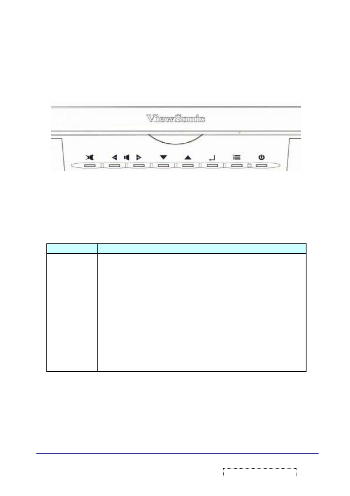
2.9 Front Panel Switches and External Connectors
2.9.1 Panel Switch Outlines.
Buttons Function
MUTE Used for mute control
< [LEFT] Navigate LEFT inside of OSD
> [RIGHT] Navigate RIGHT inside of OSD
V [DOWN] Navigate DOWN inside of OSD
^ [UP] Navigate UP inside of OSD
ENTER Used to invoke and OSD selection
MENU Used to enter and exit OSD
POWER Toggles the unit from ON to Standby and from Standby to ON. Activates the dual color
Mute Left Right Down Up Enter Menu Led Power
Outside of OSD, Decrease Volume
Outside of OSD, Increase Volume
Outside of OSD, Decrement Channel (with TV Tuner Only)
Outside of OSD, Increase Channel (with TV Tuner Only)
LED
7
ViewSonic Corporation
!
!
Confidential –DoNotCopy
Page 11
2.9.2 Front panel Shortcut:
Button Combinations Function
[RIGHT] + [DOWN]
(Hold for 0.5 Sec)
AUTO TUNE. Automatically enters Trident AutoTune Routing, to
best adjust image size, position, and Phase. N/A Digital Signal
[MENU] + [ENTER]
(HOLD for 6 SEC)
[MUTE] + [RIGHT] + [DOWN]
(Hold for 3.0 Sec)
[MENU] + [LEFT] OSD LOCK TOGGLE. See OSD Spec for detail
[MENU]+[UP]+[RIGH]
(Hold for 0.5 Sec)
[UP]+[DOWN]+[LEFT]+[RIGHT]
(Hold for 2 Sec)
[MENU] + [RIGHT] POWER LOCK. See OSD Spec for detail
[RIGHT]
(When OSD NOT Active)
[LEFT]
(When OSD NOT ACTIVE)
[UP]
(When OSD NOT ACTIVE)
[DOWN]
(When OSD Not Active)
SERVICE MODE. (Alignment Test Procedure Mode)
FULL RESET. See OSD Spec for detail
OSD Upgrade Procedure Mode. (Press the keys, than plug in the
power cable)
BURN IN MODE. (Press the keys, than plug in the power cable)
VOLUME DOWN
VOLUME UP
Channel UP (only when TV Tuner is present)
Channel DOWN (only when TV Tuner is present)
2.9.3 External Connector:
Connector Function
DC-In 12VDC input connector
VGA Standard VGA input connector
DVI-D Standard DVI input connector (DVI-D)
VXP VXP connector for A/V connection. See section
Audio out Audio output to speakers (3.5∅mm Jack, color coded)
Audio in Audio input from PC (3.5∅mm Jack, color coded)
Headphone Headphone connection on front panel. (3.5∅mm Jack,color coded)
8
ViewSonic Corporation
!
!
Confidential –DoNotCopy
Page 12
3.1. Factory Compatibility:
STANDARD
INDUSTRY 640x350 @ 70Hz YES 1280 x 700* YES
VESA 640x350 @ 85Hz 37.861 YES 1280 x 700* YES
INDUSTRY 640x400 @ 70Hz 31.4 YES 1229 x 768* YES
VESA 640x400 @ 85Hz 37.861 YES 1229 x 768* YES
INDUSTRY 720x400 @ 70Hz 31.4 YES 1280 x 711* YES
VESA 720x400 @ 85Hz 37.927 YES 1280 x 711* YES
INDUSTRY 640x480 @ 60Hz 31.469 YES 1024 x 768* YES
VESA 640x480 @ 75Hz 37.5 YES 1024 x 768* YES
VESA 640x480 @ 85Hz 43.269 YES 1024 x 768* YES
VESA
GUIDE
VESA 800x600 @ 75Hz 46.875 YES 1024 x 768* YES
VESA 800x600 @ 85Hz 53.674 YES 1024 x 768* YES
MAC 832x624 @ 60Hz YES 1024 x 768* YES
MAC 832x624 @ 75Hz 49.11 YES 1024 x 768* YES
INDUSTRY 1024x768 @ 43iHz
VESA 1024x768 @ 60Hz 48.363 YES N/A YES*
VESA 1024x768 @ 75Hz 60.023 YES N/A YES*
VESA 1024x768 @ 85Hz 68.677 YES N/A YES*
GTF 1152x864 @ 60Hz 53.7 YES N/A YES*
VESA 1152x864 @ 75Hz 67.5 YES N/A YES*
GTF 1152x864 @ 85Hz 77.05 YES N/A YES*
GTF 1280x720 @ 60Hz YES N/A YES*
GTF 1280x720 @ 75Hz 56.4 YES N/A YES*
GTF 1280x720 @ 85Hz 64.3 YES N/A YES*
GTF 1280x768 @ 60Hz 47.7 YES* N/A N/A
GTF 1280x768 @ 75Hz 60.2 YES* N/A N/A
GTF 1280x768 @ 85Hz 68.6 YES* N/A N/A
VESA 1280x960 @ 60Hz 60 YES 1024 x 768* N/A
GTF 1280x960 @ 75Hz 75.2 YES 1024 x 768* N/A
VESA 1280x1024 @ 60Hz 63.981 YES 960 x 768* N/A
VESA 1280x1024 @ 75Hz 79.976 YES 960 x 768* N/A
GTF 1920x1080 @ 30Hz YES 1137 x 768* N/A
HD* 1920x1080 @ 24P
HD* 1920x1080 @ 30i
DVD* 480i (29fps)
RESOLUTION Fh
800x600 @ 60Hz 37.879 YES 1024 x 768* YES
3. Compatibility
(Khz)
Full-Screen
FS
YES N/A YES*
YES 1137 x 768* N/A
YES 1024 x 768* YES
FAR
Aspect Ratio
1:1
One to One
Display
9
ViewSonic Corporation
!
!
Confidential –DoNotCopy
Page 13
DVD* 480i (30fps)
HD* 480P (59fps)
HD* 480P (60fps) (60Hz) 31.469 YES 1024 x 768* YES
HD* 720P (59fps)
HD* 720P (60fps) (60 Hz) 45 YES N/A YES*
HD* 1080i (25fps)
HD* 1080i (29fps)
HD* 1080i (30fps) 33.75 YES 1137 x 768* N/A
3.2. VXP Compatibility (Composite1, Composite 2, SYHS, YPBPR).
STANDARD RESOLUTION Fh
NTSC-M 525lines / 60 fields
3.58Mhz (US)
NTSC-Japan 525 lines / 60 fields
3.58Mhz (Japan)
PALB,G,N,D,H,I,M,CN
PAL-60 525lines / 60 fields
625 lines/50 Fields
4.43Mhz/3.58Mhz
4.43Mhz
YES 1024 x 768* YES
YES 1024 x 768* YES
YES N/A YES*
YES 1137 x 768* N/A
YES 1137 x 768* N/A
(Khz)
Full-Screen
FS
YES 1024 x 768 YES (700x
YES 1024 x 768 YES (700x
YES 1024 x 768 YES (833 x
YES 1024 x 768 YES (700x
AR
Aspect
Ratio
1:1
One to One
Display
525)
525)
625)
525)
10
ViewSonic Corporation
!
!
Confidential –DoNotCopy
Page 14
4. Block Diagram
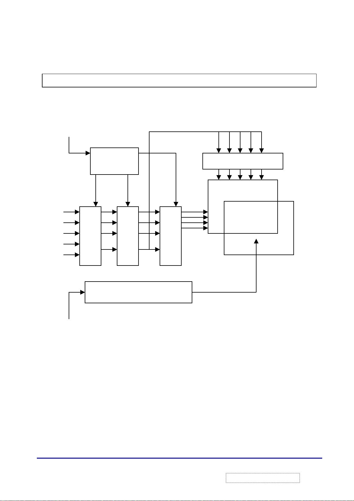
4.1 Complete TFT LCD Display Unit
ENAB
R0-R5
G0-G5
B0-B5
DCLK
Notes: The LCD module has a TFT active matrix type Liquid Crystal Display panel 1280*768 pixels, and diagonal
size of 43 cm (17.0 inch). This module support 1280*768 XGA-Wide mode (Non-interlace).
This LCD has a digital RGB interface and can display 262,244 colors.
Timing control signal is “Data enable signal: ENAB“ only. (Data Enable Mode)
Even and odd data transmitted at the timing in the interface. So the data lines are 3.( R,G,B each 6 bit*2) the
signal level of this interface
VCC +5V
Vcc
DC/DC
Converter.
Interface circuit
Control circuit
INVERTER BOARD
(External)
Data Driver
LCD Panel
Gate driver
BACKLIGHT
11
ViewSonic Corporation
!
!
Confidential –DoNotCopy
Page 15
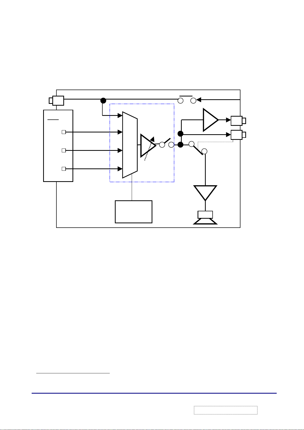
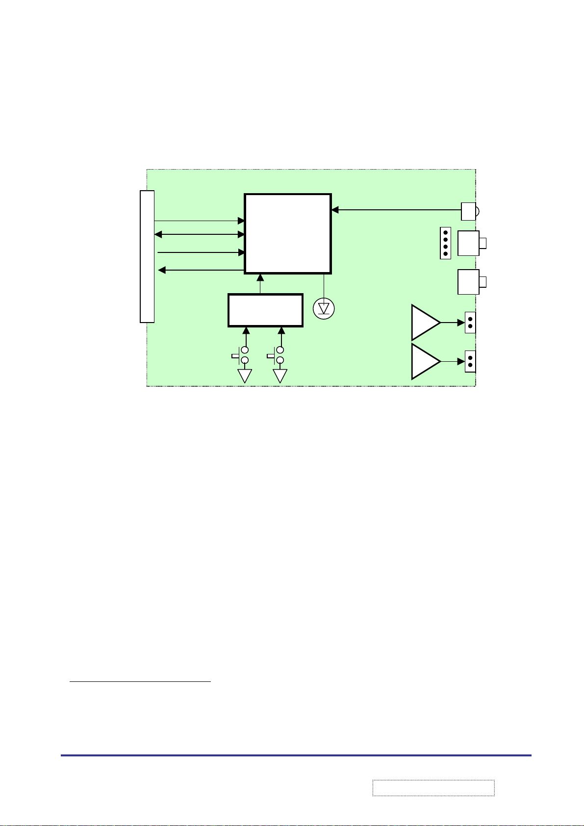
4.2 Audio Block Diagram
PC-Audio-in
VXP
Ain1
Ain2
Ain3
Description:
1. The three audio inputs from the VXP connector and the audio-in (from the SC300 or PC-audio Jack
connected to a four-way MUX. The MCU controls the MUX selection, MUTE switch and the internal
speaker’s volume. The headphone jack shall disable internal and external speakers. External-speakers
connection shall disable internal speakers
2. MUTE: Active-low TTL logic-level mute signal. When mute is held low. The select amplifier is muted.
When mute is held>high, the device operates normally
Audio MUX
I2C
MCU
Volume
MUTE
EX/IN
Internal
Speakers
Headphone
Audio-out
1
) are
12
ViewSonic Corporation
!
Confidential –DoNotCopy
!
Page 16
4.3 Front Panel Diagram
ront Panel block diagram
SCL
SDA
RST*
FRONT PANEL
IR receiver
MCU
No Mic
INT*
Headphone
EM03
1 x LED’s
8 x Buttons
2 x 10W
Amplifier
Description:
The front panel shall have an MCU that will monitor the switches, control LED’s and decode IR receiver input.
2
Communication between the MCU and the IP board shall be done via I
addition the front panel shall contain the following:
1. Headphone and microphone 3.5mm jacks and the associated headers for connection to the IP-board
2
2. 2 x 10W digital audio amplifier
amplifier output via two headers
3
An audio tactical feedback
volume shall be fixed, however the user shall be able to disable it via OSD
for front panel buttons activation shall be provided. The audio feedback
with associated support circuit. The speakers shall be connected to
C interface (MCU is the I2C slave). In
4
Speaker
2
Driving 4Ω speakers
3
Click sound
4
An “Click ON/OFF” command shall be provided as part of the I2C protocol
13
ViewSonic Corporation
!
!
Confidential –DoNotCopy
Page 17
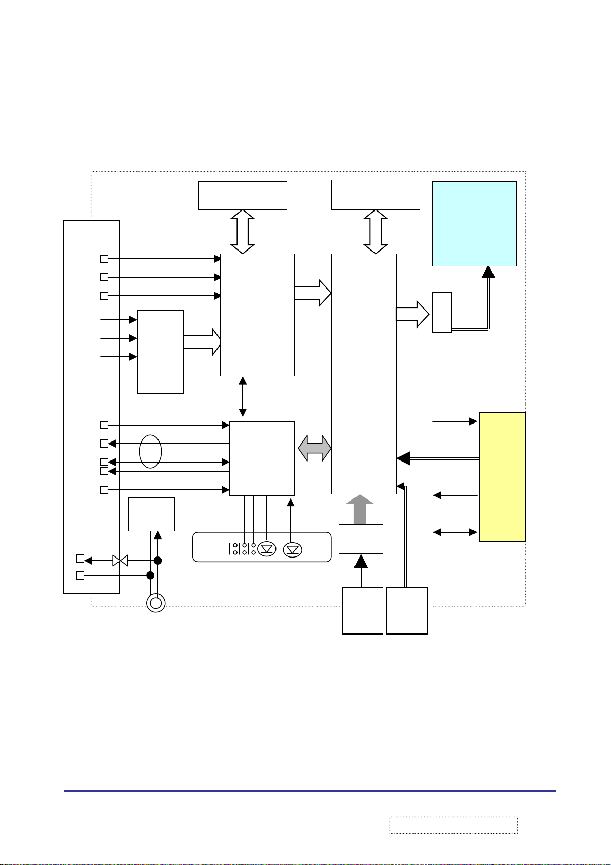
4.4 HDTV Monitor Block Diagram Graphics and Video Section
Y
V
SDRAM (8Mb)
CVBS
Sy
Sc
Pb
CPD*
SCL
SDA
RST
RDY*
+12
GND
VXP Connector
DC/DC
ADI
9883A
(No Stuff)
I2C
1.5A Fuse
DC-IN (+12V DC)
DPTV-3D
I2C
MCU
+
Flash
P
SDRAM(8MB)
PPMM
TMDS
DVI VGA
LCD Panel
TTL
+5V, +3.3V
SC300 Edg connector
Not Present
Audio
I2C
14
ViewSonic Corporation
!
!
Confidential –DoNotCopy
Page 18
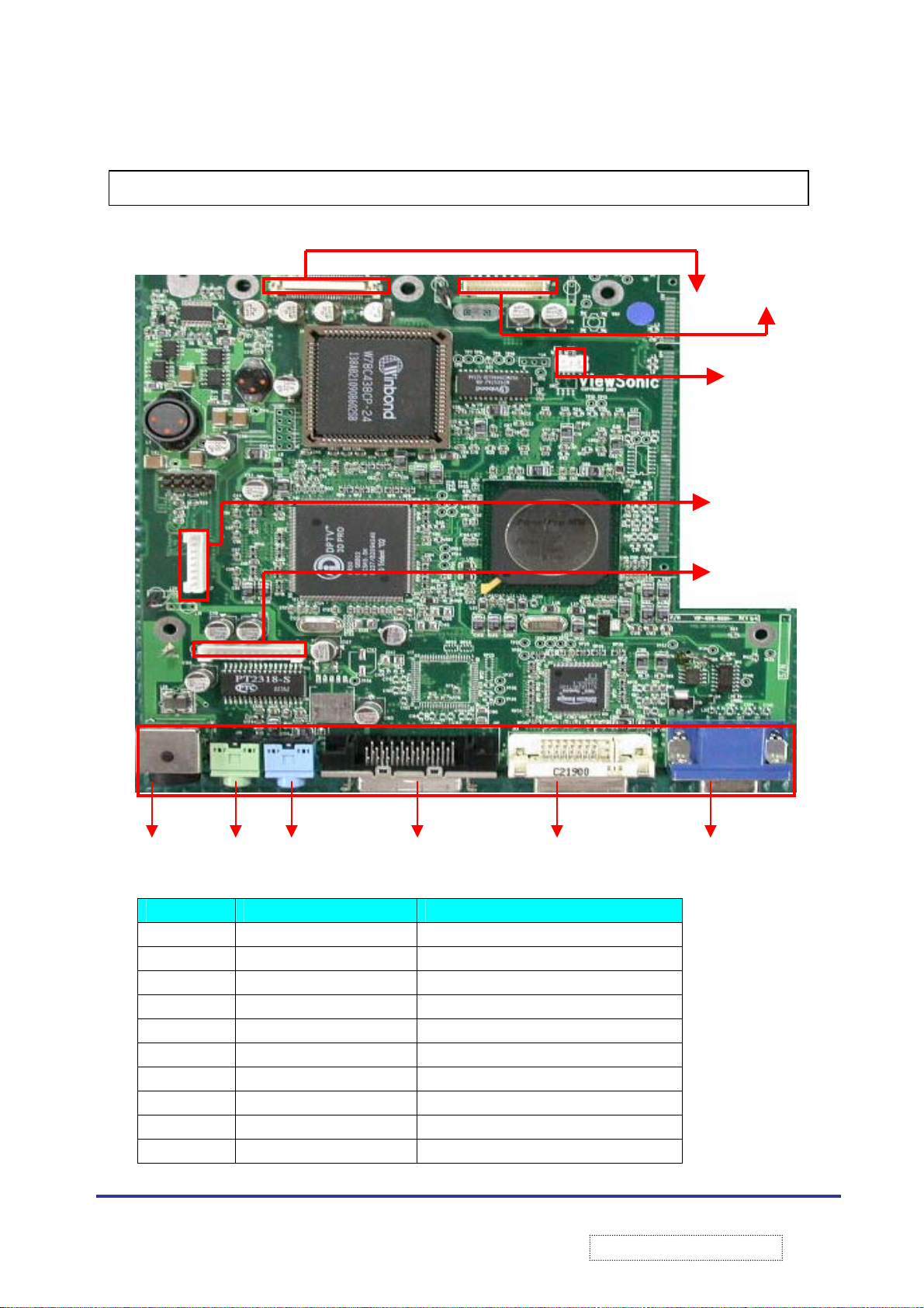
5. PCBAs Connectors Pin Assignment
5.1 Location of IP Board Connectors
J9 J10 J11 J12 J13 J14
5.1.1 J1: FPC Connector
PIN NAME DESCRIPTION
1 GND Ground
2 RE0 Register 1
3 RE1 Register 2
4 RE2 Register 3
5 RE3 Register 4
6 RE4 Register 5
7 RE5 Register 6
8 GND Ground
9 GE0 GE0
10 GE1 GE1
J1 J2
J4
J7
J8
15
ViewSonic Corporation
!
!
Confidential –DoNotCopy
Page 19
PIN NAME DESCRIPTION
11 GE2 GE2
12 GE3 GE3
13 GE4 GE4
14 GE5 GE5
15 GND Ground
16 BE0 BE0
17 BE1 BE1
18 BE2 BE2
19 BE3 BE3
20 BE4 BE4
21 BE5 BE5
22 GND Ground
23 RO0 RO0
24 RO1 RO1
25 RO2 RO2
26 RO3 RO3
27 RO4 RO4
28 RO5 RO5
29 GND Ground
30 GO0 GO0
31 GO1 GO1
32 GO2 GO2
33 GO3 GO3
34 GO4 GO4
35 GO5 GO5
36 GND Ground
37 B00 B00
38 B01 B01
39 B02 B02
40 B03 B03
41 B04 B04
42 B05 B05
43 GND Ground
44 GND Ground
45 GND Ground
46 ENAB Enable
47 GND Ground
48 GND Ground
49 DCLK Data Clock
50 GND Ground
16
ViewSonic Corporation
!
!
Confidential –DoNotCopy
Page 20
PIN NAME DESCRIPTION
51 GND Ground
52 SS SS
53 GND
54 GND
55 GND
56 GND Ground
57 VDD
58 VDD
59 VDD
60 VDD VCC
5.1.2 J2: Inverter Connector
Ground
Ground
Ground
VCC
VCC
VCC
PIN NAME DESCRIPTION
1 VIN Video input
2 VIN Video input
3 VIN Video input
4 GND Ground
5 GND Ground
6 ON/OFF Power switch
7 BRIGHTNESS 1 Brightness 1
8 GND Ground
9 BRIGHTNESS 2. Brightness 2
5.1.3 J4:IIC Debug Header Connector:
PIN NAME DESCRIPTION
1 GND Ground
2 SDA SDA
3 SDL SDL
5.1.4 J7: Front Panel Connector:
PIN NAME DESCRIPTION
1 +5VSB +5 V stand by power
2 SDA IC DATA
3 SCL IC CLOCK
4 INT* Front panel interrupt. Front panel MCU
shall assert this signal low when data is
available for the IP board. It shall be
deserted (high) when data is read by IP
Board
17
ViewSonic Corporation
!
!
Confidential –DoNotCopy
Page 21
PIN NAME DESCRIPTION
5 RST* Front panel reset. This signal is
controlled by the IP board and is used
to reset the front panel MCU
6 HDTC Power On/Off signal (Output)
7 PWR* Power ground
8 GND Ground
5.1.5 J8: Audio Board Connector
PIN NAME DESCRIPTION
1 AU_AMP_MODE Audio Amplifier Mode
2 AU_AMP_MUTE Audio Amplifier Mute
3 AU_AMP_SHDN Audio Amplifier
4 AU_AMP_FLT Audio Amplifier Filter
5 GND Ground
6 GND Ground
7 AU_PWR Audio Power VCC
8 AU_PWR Audio Power VCC
9 AUGND Audio Ground
10 AU_LO Audio Left Out
11 GND Ground
12 AU_RO Audio Right Out
5.1.6 J9:
Power Connector:
PIN NAME DESCRIPTION
1 VCC +12V
2 VCC +12V
3 GND Ground
4 GND Ground
5.1.7 J10: Line In Connector
PIN NAME DESCRIPTION
1 GND Ground
2 AU_PCL Audio Left In
3 AU_PCR Audio Right In
4 Shield GND Shield Ground
5
6
Shield GND
Shield GND
Shield Ground
Shield Ground
18
ViewSonic Corporation
!
!
Confidential –DoNotCopy
Page 22
5.1.8 J11: External Speaker Connector
PIN NAME DESCRIPTION
1 GND Ground
2 AU_PCL Audio Left Out
3 AU_PCR Audio Right Out
4 Shield GND Shield Ground
5
6
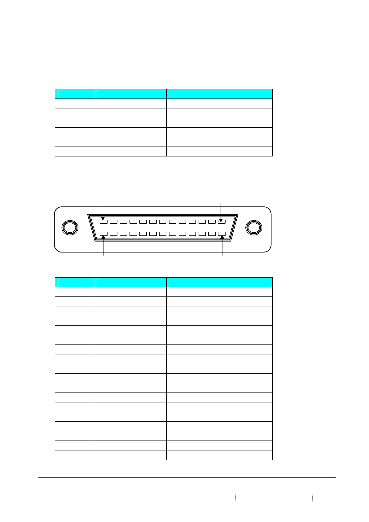
5.1.9 J12: VXP connector
VXP connector
PIN NAME DESCRIPTION
1 GND CVBS1 shied
2 GND Cvbs2 shied
3 GND SY shied
4 GND SC shied
5 GND Y shied
6 GND PB shied
7 GND PR shied
8 GND Ain 1- L/R shied
9 GND Ground
10 GND Ain2 –L/R shied
11 GND Ground
12 GND Ain 3 –L/R shied
13 GND Signal Ground
14 GND Signal Ground
15 PGND Power ground
16 PGND Power ground
17 +5V +5VDC (VXP25)
18 +12V Power (protected)
Shield GND
Shield GND
Pin-18
Shield Ground
Shield Ground
Pin-1
Pin-19Pin-36
19
ViewSonic Corporation
!
!
Confidential –DoNotCopy
Page 23
PIN NAME DESCRIPTION
19 CVBS1 Composite Video 1
20 CVBS2 Composite Video2
21 SY S-Video: Y
22 SC S-Video: C
23 Y Component Video
24 PB Component Video
25 PR Component Video
26 Ain1-L Audio Tuner Left
27 Ain1-R Audio Tuner Right
28 Ain2-L Audio input2 Left
29 Ain2-R Audio input2 Right
30 Ain3-L Audio input3 Left
31 Ain3-R Audio input3 Right
32 RDY* READY#/BUSY input
33 SDA I2C data
34 SCL I2C clock
35 RST Reset input5
36 CPD* Card Presenti
Notes: 1. Up to 500Ma can be drawn by an external device. This output shall be current limited to 750 mA
Max
2.This pin shall be grounded on the external device and used by the host to detect VXP present
5.1.10 J13: DVI Connector
PIN NAME DESCRIPTION
1 Tx/Rx 2- Tx/Rx 2-
2 Tx/Rx 2+ Tx/Rx 2+
3 2/4 Shield Ground
4 Tx/Rx 4- Tx/Rx 4-
5 Tx/Rx 4+ Tx/Rx 4+
6 DDC CLK Data Display Channel Clock
7 DDC DATA Data Display Channel Data
8 VSYNC Vertical SYNC
9 Tx/Rx1- Tx/Rx1-
10 Tx/Rx1+ Tx/Rx1+
11 1/3 Shield Shield Ground
12 Tx/Rx3- Tx/Rx3-
20
ViewSonic Corporation
!
Confidential –DoNotCopy
!
Page 24
PIN NAME DESCRIPTION
13 Tx/Rx3+ Tx/Rx3+
14 +5V_PWR +5 VCC
15 GND Ground
16 HPD HPD
17 Tx/Rx0- Tx/Rx0-
18 Tx/Rx0+ Tx/Rx0+
19 0/5 Shield Shield Ground
20 Tx/Rx5- Tx/Rx5-
21 Tx/Rx5+ Tx/Rx5+
22 CLK Shield Clock Shield Ground
23 Tx/Rx C+ Tx/Rx C+
24 TX/RX C- TX/RX C-
25 SHLD1 Shield Ground 1
26 SHLD2 Shield Ground 2
5.1.11 J14: VGA Connector
PIN NAME DESCRIPTION
1 R Red
2 G Green
3 B Blue
4 GND Ground
5 GND Ground
6 R-GND Red-Ground
7 G-GND Green-Ground
8 B-GND Blue-Ground
9 VCC +12V
10 GND Ground
11 N.C No Connection
12 SDA Serial Data input
13 H-SYNC H-SYNC(Composite sync)
14 V-HYNC V-SYNC(Composite sync)
15 SCL Serial Clock input
21
ViewSonic Corporation
!
!
Confidential –DoNotCopy
Page 25
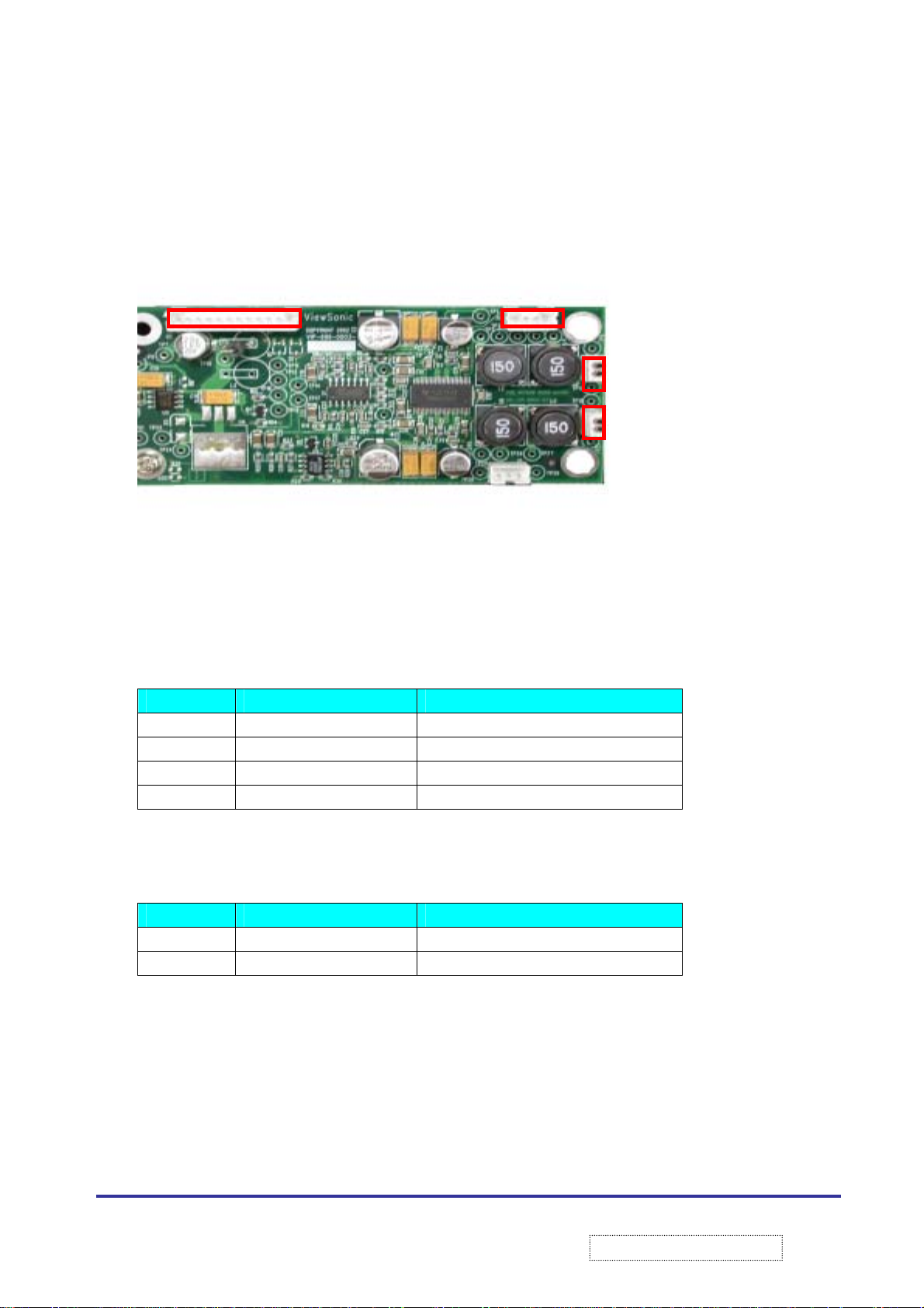
5.2 Location of Audio Board Connectors
5.2.1 J1: Audio Board to Main Board Connector
5.2.2 J2: Head Phone Connector
PIN NAME DESCRIPTION
1 HPL + Head Phone Left+
2 HPR+ Head Phone Right+
3 HP_GND Head Phone_ Ground
4 GND Ground.
5.2.3 J3 and J4: Internal Speaker Connectors
PIN NAME DESCRIPTION
1 AUD Audio
2 GND Ground
J1 J2
Same as 5.1.4 J8: Audio Board Connector
J3
J4
22
ViewSonic Corporation
!
!
Confidential –DoNotCopy
Page 26
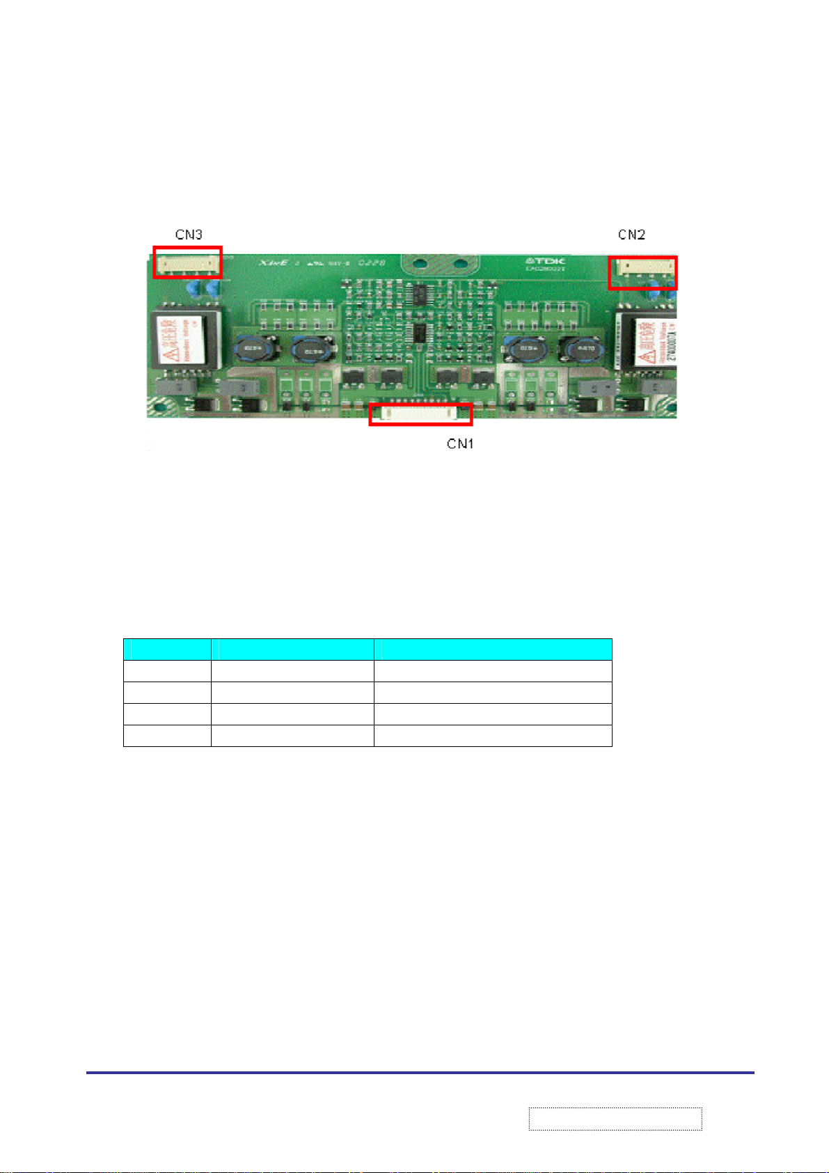
5.3 Location of Inverter Connectors
5.3.1 CN1: Inverter to Main Board
Same as 5.1.2 J2: Inverter Connector
5.3.2 CN2 and CN3: Output Connector
PIN NAME DESCRIPTION
1 HV H/V
2 HV H/V
3 N.C No Connection
4 RTN Return
Connector
23
ViewSonic Corporation
!
!
Confidential –DoNotCopy
Page 27

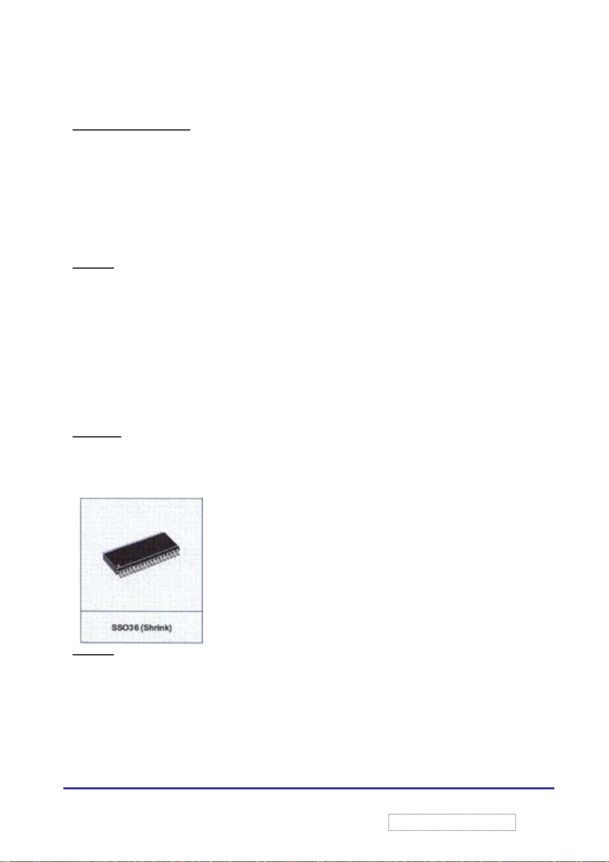
6. IC Descriptions
6.1
PT2318(U15):
POSITION IN IP BOARD:
PT2318 is a sound fader controller utilizing CMOS technology specially designed for car radio hi-fi audio
application. four selectable stereo input,1 mono, bass, treble , volume, balance and fader controller. mute function
and special loudness feature which is automatically controller in combination with the volume level setting are all
built into a signal IIC bus stereo preamplifier chip having the high performance and reliability
Features:
1. CMOS Technology
2. IIC controller bus interface
3. 4 selectable stereo input
4. 1 mono input
5. Volume, balance, and fader control
6. Bass & Treble control
7. Noise reduction circuit provided
8. External equalizer interface provided
9. Mute control at Audio signal zero crossing
10. Internal power on reset function
11. Mute function controlled via the IIC bus or pin
12. Special automatically loudness feature in combination with the volume setting
6.2
PIC16F73(U1)
POSITION IN FRONT BOARD
High performance:
1. High performance RISC CPU
2. Only 35 signal word to learn
3. Operating speed: DC –20 MHZ ,DC-200 ns instruction cycle
4. Up to 8k*14 words of flash memory
Up to 368*8 bytes of data memory
5. Eight level deep hard stack
6. Processor read access to program memory
24
ViewSonic Corporation
!
!
Confidential –DoNotCopy
Page 28
Special Controller Feature:
1. Power On Reset (POR)
2. Power Up timer and Oscillator start up. Timer
3. Watchdog timer (WDT) with its own on-chip RC
Oscillator for reliable operation
4. Programmable code protection
5. Power saving sleep mode
6. Selectable oscillator options
Features:
1. Timers: 3
2. I/O port: 3
3. Flash program memory: 4k (14 bit word)
4. Interrupts: 11
5. 8 bit analog to digital modules: 5 input channels
6. Instruction Set: 35 set
7. Data memory: 192 bytes
6.3
EM03B(U2)
TOUCH SENSOR
8-CH CAPACITIVE SENSOR.
POSITION IN FRONT BOARD:
The EM03 touch sensor designed specifically for touch controls. it’s
Features:
provide stable sensing under a wide vanity of changing condition it will
project a sense field through almost any dielectric. It is designed
specifically for human interfaces like control panels. application lighting
controls or anywhere a mechanical switch or button may be found. the
device is designed to detect touch on up to 8 point independently.
6.4.1.8-CH capacitive sensor
6.3.2.Touch-button through any dielectric
6.3.3.Separated each channel
6.3.4.TTL output
6.3.5.Buzzer Oscillator
6.3.6.Internal holding output
25
ViewSonic Corporation
!
Confidential –DoNotCopy
!
Page 29

6.4
TRIDENT 3D DPTV
POSION IN IP BOAD (U10).
The chip utilizes two kind of resource: memory and register. the DPTV use a 8 bit address
Architecture, and therefore has 256 ports available. To across all the memory Space and
register efficiently. please refer to following instructions:
6.5.1.The register are divided into pages, each pages contains at most 224 (E0 HEX) register (0~DF)
6.5.2.The pages control register FEH & FFH. The register FEH is used to control bus (I
the registers. The register FFH is used to control register pages which are enable to receive data
6.5.3.Memory access is managed by:
FEH: Data port (Both Read/Write)
FAH~F8H: Address port (Both Read/Write)
F0H~F2H: Some Control bits are spread around F0H~F2H
Features:
A. Display function register set.
The display group can be classified into five separate section, namely, main display SVGA, OSD, PIP, and Hard
course display
B. Capture register set
The capture consists of two separate components. the main picture and PIP (Picture In Picture) block the
MP accepts analog signal through analog front end (AFE), and is processed through a TV decoder.
The TV decoder is equipped with a monitor decoder that can identify the area of picture containing motion so that
a good mix between the temporal and spatial (2D-Filiter) can be determined
the PIP block accepts a digital signal and provides a preferred format like the main picture block.
C.OSD.(On Screen Display):
An OSD block consisted of a pixel bitmap of OSD.4 bits per pixel. there are total of 16 colors for the
OSD display. there is 16*29 bits lock up table for DPTV3D each 4-bits OSD index corresponds to a 29 bits color
attribute, including 24 bits for the RGB true color data, 1 bit for blink function which enables/disables color blinking
the blinking frequency is controlled by a register another 4 bits are defined as a blend factor which can decide
16-transparancy degrees of the current OSD color with the background OSD
D. Display CRTC
DPTV display mode can be categorized by the following parameters:
D-1.Reflash rate
D-2.Number of pixels per scan line
D-3.Number of scan line per frame
D-4.Interlaced or progressive display mode
D-5.Tv tube horizontal frequency
C)or parallel that access
2
26
ViewSonic Corporation
!
!
Confidential –DoNotCopy
Page 30

E. Memory Control
Depending on the actual system configuration and application, the DPTV display frame buffer could be used to
store the following display objects , each with varying sizes:
E.1.Main picture display
E.2.Picture In Picture display buffers
E.3.Motion detection feature buffers
E.4.Hard course buffers
F. Video quality enhancement features
F.1.Noise Reduction
F.2.Blue Screen and protect screen
F.3.Auto Contrast and saturation adjustment
E.4.Vertical Blanking Interval (VBI)
Signal that “hides” the sweep of the electron beam from the button to the of screen
E.5.Analog to digital signal converter (ADC)
Digitalizing video requires fast sampling of 10 –50 million samples per/sec
G. SVGA overlay
To overlay SVGA signal with DPTV display output
H. Panorama mode setting.
DPTV support wide screen TV it can be display in 4:3 and 16:9 mode. cinema and Panorama four possibilities:
H.1.source signal is normal NTSC or PAL signal displays in normal 4:3 mode
H.2.source signal is 16:9. displays on normal 16:9 tube
H.3.source signal is normal signal. Extends to 16:9 mode
H.4.source signal is 16:9 signal. Shrinks to 4:3 mode
I. TVD3, NTSC, PAL, SECAM video decoder.
The integrated NTSC, PAL, SECAM, TV decoder can take an analog TV signal and convert it to a digital format
analog signal can be in the composite S-VIDEO or component format. the two internal analog switches can be
programmed to select different signal formats. the select analog TV signal is sent to the Automatic Gain
control(AGC) and then to a 10 bit ADC. this input sample ADC’s NTSC, PAL, SECAM, and all progressive modes
27
ViewSonic Corporation
!
!
Confidential –DoNotCopy
Page 31

6.5
U11 (PanelPro
POSITION IN IP BOARD U11.
General description feature:
Panel
PRO mm integrated a clamping, pre-amp, ADC, sync, separator, scaling engine, external SDRAM/SGRAM
interface for frame to frame conversion and video overly display and micro-controller interface circuitry the chip
also accepts dual 24 bits digital RGB port and SYNC input and separate 8 bits /16 bits digital port for video
decoder connection. The SYNC inputs interfaces directly with any VGA/SVGA/XGA/UXGA/ graphics board or any
other compatible source. Panel
signals form video decoder , or digital signals from external DVI ,transmitter and deliver 48 bits of digital data ,
and necessary control signals for driving an 8 bit or 6 bit TFT LCD panel and also support built in graphics mode
OSD. Also front_Base OSD and external OSD are support when no external SDRAM/SGRAM support chip
supports input video and graphics modes up to 1600*1200@60 HZ
Features:
6.6.1.PGA (ClamPing, Pre amp (Gain control), and ADC
-24 bit Y
-Three high speed 8 bit ADC for analog VGA.HDTV signal input
-External pre-amp option support
6.6.2.PLL.(Phase Locked Loop)
-On chip line lock PLL to recover the VGA/Y
-PLL clock delay adjustment.(DLL)
-On Chip low noise memory PLL clock
6.6.3.DSS.(Digital Sync Separator)
-On chip SYNC separator for SOY(Sync On Y) and SOG (Sync On Green) signal input
6.6.4.I
- Support 8 bit Micro Process Unit (MPU) bus control
- Support I
6.6.5.INTERFACE
-Panel power back and light power turn on /off sequence control
6.6.6. VGA:
-24/48 bit VGA (RGB) HDTV data input
-VGA display mode auto decoder
-Support RGB/HDTV port capture window
-VGA auto adjust function
flat panel is a high performance controller chip to allow LCD monitor or to become user-friendly. PanelMM
MM
pbPr
2
C:
2
)
MM
PRo
input support
C serial communication
mm also accepts 8/16 bits YUV CCIR601 or 8 bit CCIR656 format video
pbPc/Ycbcr
sampling color
28
ViewSonic Corporation
!
!
Confidential –DoNotCopy
Page 32

6.6.7. VIDEO (HDTV) & CCIR(SDTV)
-Programmable TV field decoder
-Video brightness/contrast/sat/hue and sharpness adjustment
-Support external OSD input with alpha blending display
6.5.8. FRMAE BUFFER
-Support video compress (4:4:4 =>4:2:2) and un-compress (4:2:2 =>4:4:4) to increase memory bandwidth
performance:
-Support double buffer read/write access mode
-Built-in Graphics (Bitmap) OSD
-Zoom in display function
-Support central display function
-1-line shift for main picture and overlay picture (PIP) output display
6.5.9. TFT LCD DISPLAY
-Line buffer as the FIFO mode read/write control (line buffer control mode)
-Support YpbPr /Y
-Support on chip digitally color temperature/brightness/contrast/ adjustment
-Support PIP overly display with board
-Support 10 bits color gamma table correction. (LUT)
6.5.10.CHIP FEATURE.
-Support video input up to 1600*1200(XUGA)@60 HZ frame flash rate and output video up to 1600*1200@60 HZ
frame flash rate
6.6
U6(W78C438CP-40)
POSITION IN IP BOARD.
General description:
-Provides two dedicate address ports AP5~AP6 that served as address output for 64 kb of memory and one
address/data port (db4) that sever as ROM code input and external RAM data input /output
Features:
6.7.1.bit CMOS micro-controller
6.7.2.Fully static design
6.7.3.DC to 40 MHZ operation
6.7.4.ROM less operation
6.7.5.One 8 bits data address port
6.7.6.Two 8 bit and one 4 bit address port
6.7.7.Three 16 bits timer/counter
6.7.8.Four external interrupt
6.7.9.Built in power manager
two color space conversion
cbCr
29
ViewSonic Corporation
!
Confidential –DoNotCopy
!
Page 33

Type
ROMLESS 256 40
RAM
I/O PIN
External
1M
Speed MHZ
40MHZ
Timer counter
3 5 I/O PORT
Additional
30
ViewSonic Corporation
!
!
Confidential –DoNotCopy
Page 34

7. Wave Form
7.1 Signal: CH1 Data OSC output between Y1 and Y2 position signal
Location: Front BD / U1
Notice:
7.1.1 If front board can’t work, please measure the signal U1(PIN 9,10) wave, as picture. Its will effects IR
receiver operation and Front BD functional if key pad can not work please check U2 chip
7.1.2 If output U2 chip without signal wave , please check s1~s7
7.2 Location: Front board / U2
CH1: Signal of S1~S8
31
ViewSonic Corporation
!
!
Confidential –DoNotCopy
Page 35

Notice:
7.2.1.
Please check u2 chip (pin14,13,24,23,5,6,31, and 32), whether have output signal or not. such as attach file
signal
7.2.2.
Its will effect keypad board each key function normal situation and measure s3,4,8,7,2,1,5 and s6 in front of
register's output
7.3 Location: IP board / U10
Ch1:DPTV Output Signal Of Pin 163 and Pin 164
Notes:
7.3.1.
Please check Y
signal level. On the other hand, if DPTV without signal output, please do it next and check U10 pin 96 till U31 and
U34 clock output status
oscillator waveform signal level, does it work well or not. Its will effect DPTV, HSYNC, VSYNC
2
32
ViewSonic Corporation
!
!
Confidential –DoNotCopy
Page 36

7.4 Location: IP board / U31
Ch1:DPTV Clock Enable Signal Of the Pin 67
Ch2:DPTV Clock Signal Of The Pin 66
Notes:
7.4.1
Check SDRAM output signal between U10 and U31 even U34 interface signal measurement. It will effects chips
on normal output, boot up, and output display situations
7.5 Location : IP board / U28
Ch1:PPMM Data Clock Enable Of The Pin 67
Ch2:PPMM data Clock Of The Pin 66
33
ViewSonic Corporation
!
!
Confidential –DoNotCopy
Page 37

7.6 Location: IP Board / U10.
Ch1:DPTV H-SYNC of Pin 34
Ch2:DPTV V-SYNC of the Pin 35
7.7 Location: IP Board / U10
Ch1:DPTV H-SYNC Of The R213
Ch2:DPTV V-SYNC OF The R214
34
ViewSonic Corporation
!
!
Confidential –DoNotCopy
Page 38

7.8 Location: IP Board / U11.
Ch1:PPMM H-Signal Of the R193
Ch2:PPMM V-Signal Of The R194
7.9.Location: IP BOARD / U11
Ch1: PPMM Data Clock of R195
35
ViewSonic Corporation
!
!
Confidential –DoNotCopy
Page 39

7.10.Location: IP BOARD / J14
Ch1: VGA H-Signal IN
Ch2: VGA V-Signal IN
36
ViewSonic Corporation
!
!
Confidential –DoNotCopy
Page 40

g
8.1 No Display
backli
Start
Is LED on?
Yes
LED is Green?
Yes
Is
ht On?
Yes
Does BIOS
outputs?
Yes
End
8. Trouble Shooting Guide
No
No
No
No
1. Is adaptor’s output +12V
2. Check DC jack .is well contact
3. Is DC-DC voltage OK
4. Check LED signa
1. Is it in POWER saving?
2. Check video cable?
3. Is the timing support?
1. Check inverter is OK?
2. Check CNT1 connector is well contact?
3. Check FPC cable
1. Check BIOS Pin36 of U6..
2. Check U25 +5V
37
ViewSonic Corporation
!
!
Confidential –DoNotCopy
Page 41

8.2 R.G.B COLOR CAN NOT DISPLAY EXACTLY.
1. Check pin 1,2,3,13,14 output?
2. Is 5V normally output?
Start
Input signal
Ok ?
J14 Output
Correct?
Check VGA
R, G, B input?
End
No
Yes
No
Yes
No
Yes
Yes
1. Check video cable is well contact
2. Check setting of host system
1. Check Pin 9 +5v
2. Check pin14 of U14 should be
+3.3 v
1. Check C318, C322, C317 output?
1. Check D5, 6, 7, 12, 13 output
38
ViewSonic Corporation
!
!
Confidential –DoNotCopy
Page 42

8.3 DC-DC CONVERTER PROBLEMS
1. Is J1 connector OK?
2. Is panel work OK?
3. Check OSD color settings
Start
Input signal
Ok ?
Yes
J14 Output
Correct?
Yes
Check R195
output?
Yes
Yes
End
No
No
No
1. Check video cable is well contact..
2. Check setting of host system.
1. Check Pin9 +5v.
2. Check J1 connector is well
contact
1. Check U11 Pin AD20
39
ViewSonic Corporation
!
!
Confidential –DoNotCopy
Page 43

8.4 TROUBLE READING DDC (DISPLAY DATA CHANNEL).
4. Check R50 V clock output
5. Check R315 power supply +5V
Start
Yes
No
Input signal
Ok?
Yes
No
J13 output
correct ?
Yes
No
Check U18
Pin 44?
Yes
Yes
End
1. Check video cable is well contact
2. Check setting of host system
1. Check Pin 6 data clock
2. Check u42 Pin 7
Check R328 and R85 output
3.
1. Check A14 PPMM clock
40
ViewSonic Corporation
!
!
Confidential –DoNotCopy
Page 44

8.5 POOR IMAGINE QUALITY.
p
Start
Imagine size
OK?
Vertical
Stripe?
Horizontal
Stri
e?
Position
Shift?
Too dark or
Bright?
Yes
Yes
Yes
Yes
Yes
No
No
No
No
No
1.Is scaling to full screen
2.Do auto sync function
work well under full
screen supported
3.Check power 3.3 v
1.Coes auto sync adjust
function work well
2.Is the timing support?
3.Adjust H-size item of
OSD
1. Does auto sync adjust
function work well .
2. Is the timing support?
3. Adjust H-size item of
OSD
1. Does auto adjust
function work well
under pattern.
2. Is the timing support
1. Adjust contrast.
2. Adjust user R.G.B
3. Check brightness
Yes
Color
Unbalance
Yes
End
No
1. Select preset color
temperature.
2. Adjust user color
R.G.B
41
ViewSonic Corporation
!
!
Confidential –DoNotCopy
Page 45

8.6 AUDIO PROBLEM.
board have power?
Start
Yes
Signal input ok?
Yes
Does audio
Yes
Is speaker
output ok ?
Yes
End
No
No
No
1. Check Audio Cable.
2. Check Audio Source from U2
1. Check U2 PIN 21 and 28
+12 V OK
2. Replace U1 chip
1. Check J3, J4, J2, and J1
connector are well contact
2. Replace U2 chip
42
ViewSonic Corporation
!
!
Confidential –DoNotCopy
Page 46

8.7 OSD PROBLEM
Start
No video?
Unstable
Display?
End
Yes
Yes
Yes
No
No
1. Check the power cable is connected
2. Re flashing new OSD programming
on U27
3. Check U6 (ADOAD7) .
1. Check U10 pin 165 to pin 172 data
2. Check U11 port 0 to port 7.
3. Check U11 of Y3 status
43
ViewSonic Corporation
!
!
Confidential –DoNotCopy
Page 47

8.8 IR PROBLEM.
Start
Does remote
Control can works?
Is IR receive
can works?
End
Yes
Yes
Yes
No
No
1. 1. Check the firmware of U1 chip
is latest
2. Check Y1 and Y2 output status
should be normally ( as like 7.1)
1. Measure the pin3 of U3 voltage
should be normally output.
2. Check the pin2 of U3 data
Is correct
44
ViewSonic Corporation
!
!
Confidential –DoNotCopy
Page 48

8.9 KEYPAD Board Problem.
Start
Does every
Function can
works ?
Does Voice
have output
as well ?
End
1. Check U2 wave level for each function
Should be normally output as if 7.2 (#REF).
2. Check Y1 and Y2 must have normally
Output as like 17.1
1. Check Phone jack cable should be
connected
2. Check pin 31 of U15 output voltage.
3. Check pin4 of J8 should be 5 V
4. Check pin 4 of J7 should be 5 V ,either
45
ViewSonic Corporation
!
!
Confidential –DoNotCopy
Page 49

9. Replacement Part list
9.1. Main Units Parts.
Items P/n Description Qty.
1 41-00002-006 EMI Gasket 20W*1H*100Lmm 1
2 41-00002-008 EMI Gasket 10W*10.5H*155Lmm 1
3 41-00002-009 EMI Gasket 10W*10.5H*40Lmm 3
4 41-00002-010 EMI Gasket 10W*10.5H*185Lmm 1
5 52-00002-011 EMI Gasket 10W*10.5H*280Lmm 1
6 41-31013-001 EMI Gasket 773GT 10*5*15mm 3
7 41-31015-001 EMI TAPE 80013 15*20 mm 1
8 41-55000-001 EMI core 20.5L*20W*33H(mm) 1
9 41-55002-005 EMI Gasket I/O TAPE 22W*1.4H*1.75Lmm 1
10 42-50115-001 Cable power cord 1830mm SP30+1S14 1
11 42-55001-001 W.A 9/9P UL 1095#28 L180mm 1
12 42-55002-001 W.A 12/12P UL 1095#28 L110mm 1
13 42-55003-001 W.A 8/8P UL 1571#28 L250mm 1
14 42-55004-001 W.A 2/2P UL 1571#28 L170mm 1
15 42-55005-001 W.A 2/2P UL 1571#28 L350mm 1
16 42-55006-001 W.A 4/4P UL 1095#28 L400mm 1
17 42-55007-001 ASS FPC FOR Fujitsu Panel 1
18 42-55008-001 Cable VGA 1800mm 1
19 42-55009-001 Cable Audio 1800mm 1
20 42-55010-001 Cable SCHUKO 1800mm 1
21 42-55011-001 W.A 3/3P UL 109#28 L630mm 1
22 44-55001-001 INVT Fujitsu FLC43XWC6V 1
23 47-55001-001 AC ADPTR IN:AC100-240V 2.5A Out: DC 12 1
24 48-55001-001 TFTP LCD Wide TFT LCD 17’ 1
25 49-55001-001 Remote Control RC-36B king Ming Kai 1
26 51-00001-001 Cable Tie PG-YJ-80 1
27 51-53409-001 ESD Bag LDPE PV740 1
28 51-55001-001 Front Cover abs 1
29 51-55002-001 Rear Cover abs 1
30 51-55004-001 Hinge cap abs 1
31 51-55006-001 Front arm cover abs 1
32 51-55007-001 Rear arm cover abs 1
33 51-55008-001 Stand base cover abs 1
34 51-55010-001 Cable Clamp Nylon66 PCW-50H 1
35 51-55011-001 Viewsonic Logo abs81.7*32.0mm 1
36 51-55013-001 Wire Mount NYLCN66 FW-IS-3M 4
46
ViewSonic Corporation
!
!
Confidential –DoNotCopy
Page 50

Items P/n Description Qty.
37 51-55014-001 Connector FILM clear Mylar 1
38 51-55015-001 Handle plate pp natural 1
39 51-55016-001 Hand holder pp Natural 1
40 51-80102-001 Open close bushings SB-0609A 2
41 52-55002-001 Cushion rubber (circle) 2
42 52-55003-001 Rubber for VESA mount N1700W 4
43 52-55004-001 Rubber foot (L/R) 2
44 52-55005-001 Rubber foot (front) 1
45 52-55006-001 Rubber foot (back) 1
46 61-55001-001 Main Chassis plate 1
47 61-55005-001 Hinge Tilt N1700W 1
48 75-55002-001 Front panel assembly 1
49 75-55003-001 Assembly speaker soundmatter 2
50 80-55001-001 PCBA IP board Rev.0019 1
51 80-55002-001 PCBA Audio board Rev.0004 1
52 80-55003-001 PCBA Front panel board Rev 0011 1
53 85-00523-050 Screw hex head m3*h5*l5 Ni NYLOK 2
54 85-005AG-075 Screw Pan Head m2*l8 NI NYLOK 4
55 85-1A122-080 Screw Pan Head m2*l8 Ni 2
56 85-1F123-060 Screw Pan MECH W/SP m3*8 Ni 2
57 85-1F323-060 Screw Pan MECH w/sp m3*6 BLACK 4
58 85-2A624-080 Screw Bin MECH m4*8 Black/NYLOK 4
59 85-4A524-080 Screw flat head MECH 3
60 85-SA123-120 Screw Bin Tap/2Lm3*12 NI 2
61 85-SA124-120 Screw Binding Tap m4*L12 4
62 85-WA123-080 Screw Pan tap m3*8 Ni 1
63 85-WA323-060 Screw Pan tap m3*6 black 4
64 85-WD123-110 Screw Pan Head flat washer 2
65 85-YA123-080 Screw flat tap m3*8 Ni. 4
47
ViewSonic Corporation
!
!
Confidential –DoNotCopy
Page 51

9.2 Accessory Kit Parts.
Items P/n Description Qty.
1 36-55001-001 N1700w Quick Start Card 1
2 36-55004-001 N1700w CD Wizard (CD+Book). 1
3 42-50115-001 Cable Power Cord 1830mm SP30+1 1
4 42-55008-001 Cable VGA 1800mm 1
5 42-55009-001 Cable Audio 1800mm 1
6 42-55010-001 Cable SCHUKO 1800mm 1
7 49-55001-001 Remote Control RC-36B 1
48
ViewSonic Corporation
!
!
Confidential –DoNotCopy
Page 52

10. Complete PCBAs Part List
10.1 PCBA IP Board
Location1 Location2 Location3 Location4 P/N Description Q’ty
80-55001-001 PCBA IP BD REV.0019 N1700w 1
00-55001-001 *PCB L:8 1.6mm IP BD REV.04 N1700w 1
L101,L103,L1
04,R16,R22,
R23,R72,R74
,R76,R79,R8
1,R96,R98,R
104,R111,R1
12,
R4,R9. 01-01014-501 RES RP 1Ω 1% 1/4W #1206 2
R5,R6,R7,R8. 01-10036-501 RES RP 10 5% 1/16W CHIP #0603 4
R13,R14. 01-10038-501 RES RP 10 5% 1/8W CHIP #1206 2
R270,R271,R
278,R279,R28
0,R281,R288,
R289.
R12. 01-10216-502 RES RP 1.02K 1% 1/16W CHIP #0603 1
R17,R29,R38,
R47,R53,R70,
R71,R90,R93,
R103,R130,R
136,R137,R15
1,R166,R167,
R172,R202,R
223,R224,R22
5,R235.
R21,R26,R28
,R34,R57,R8
0,R83,R84,R
86,R88,R94,
R99,R105,R1
07,R108,R11
5,R117,
R2. 01-11216-502 RES RP 1.13K 1% 1/16W CHIP #0603 1
R253A. 01-12119-501 RES RP 121Ω 1% 1/10W #0603 1
R253B. 01-14019-501 RES RP 140Ω 1% 1/10W #0603 1
R15. 01-18216-502 RES RP 1.82K 1% 1/16W CHIP #0603 1
R325,R327. 01-20236-501
R237,R274,R
277.
R273,R276. 01-22236-501 RES RP 2.2K 5% 1/16W CHIP #0603 2
R11. 01-30316-501 RES RP 30.1K 1% 1/16W CHIP #0603 1
R3. 01-30436-501 RES RP 301K 5% 1/16W CHIP #0603 1
RP1,RP2,RP3
,RP4,RP5,RP
6,RP7,RP8,R
P9,RP10,RP1
1,RP12,RP13,
RP14,RP15,R
P16,RP17,RP
18,
R27,R30,R31,
R32,R33,R36,
R37,R39,R40,
R50,R54,R55,
R56,R65,R66,
R100,R101,R
R121,R122,R129
,R138,R157,R15
9,R170,R179,R1
84,R231,R242,R
253,R265,R283,
R284,R297,
01-10136-501 RES RP 100 5% 1/16W #0603 8
,R223,R224,R22
5,R235.
R141,R145,R1
48,R149,R154,
R155,R158,R1
60,R161,R177,
R178,R180,R1
82,R200,R203,
R204,
01-20316-501 RES RP 20K 1% 1/16W #0603 3
,RP19,RP20,RP2
1,RP24,RP26,RP
28,RP29,RP30,R
P31,RP32,RP33,
RP34,RP35,RP3
6,RP37,RP38
R106A,R110,R11
4,R116,R120,R1
23,R124,R128,R
131,R133,R134,
R135,R139,R142
,R144,R147
R295A,R301,R30
5,R312,R313,R3
17,C377,C387,C
389,L83,L84,L87.
01-10236-502
R215,R264,R266
,R306,R315,R31
8,R329,R330,R3
31,C424,C425,C
426,C427,C428,
C429.
,RP39,RP40,RP4
1,RP42,RP43,RP
44,RP45,RP46,R
P47,RP48,RP49,
RP50,RP51,RP5
2,RP53,RP54
R150,R152,R153
,R156,R181,R18
3,R185,R187,R1
88,R189,R192,R
193,R194,R195,
R210,R211,
01-00036-502
01-10336-502
,RP55,RP56,RP5
7,RP58,RP59,RP
60,RP61,RP62,R
P63,RP64,RP65,
RP66,RP67,RP6
8,RP69,RP70
R212,R213,R218
,R238,R239,R24
0,R244,R246,R2
47,R248,R259,R
260,R267,R286,
R287,R299,
01-33036-501
01-33036-502
RES RP 0 5% 1/16W CHIP #0603;" TA -I
TECHNOLOGY"
RES RP 1K 5% 1/16W #0603;"TA-I
TECHNOLOGY"
RES RP 10K 5% 1/16W CHIP
#0603 ;"TA-I TECHNOLOGY"
RES RP 2K 5% 1/16W CHIP #0603; 'TA-I
TECHNOLOGY"
RES RP 33 5% 1/16W x4 V8V 8P SMD
"PANA SONIC","TA-I"
RES RP 33 5% 1/16W CHIP #0603; "TA-I
TECHNOLOGY"
44
22
48
70
76
2
49
ViewSonic Corporation
!
!
Confidential –DoNotCopy
Page 53

102
R92,R236. 01-33236-501
R336,R337,R
338.
R1. 01-36216-501 RES RP 3.65K 1%CHIP #0603 1
RB1,RB2.
R314. 01-39136-501 RES RP 390 5% 1/16W CHIP #0603 1
R91. 01-47236-501 RES RP 4.7K 5% 1/16W CHIP #0603 1
R95,R201,R2
33,R234.
R209. 01-56116-501 RES RP 560 1% 1/16W CHIP #0603 1
R206,R245,R
249,R250,R2
51,R285,R29
8,R300,R326,
R334,R335.
C6,C7,C9,C10
,C136,C137,C
158,C163,C16
4,C203,C209,
C221,C228,C
279,C280,C28
1,C282
C21,C23,C26
,C41,C42,C2
20,C222.
C30,C37,C45,
C52,C56,C60,
C61,C66,C76,
C79,C83,C86,
C116,C117,C
119,C120,C14
8,C149
C17,C18,C53,
C118,C126,C
127,C169,C18
3.
C128,C131,C
134,C135.
C15,C151,C1
59,C160,C17
4,C175,C192,
C196,C286,C
293,C336,C3
91.
C1,C3,C8,C14
,C27,C28,C29
,C31,C32,C33
,C34,C35,C36
,C38,C39,C43
,C44,C46,C47
,C48,C49
C24,C206,C3
61.
C359,C349. 02-15877-102
C210,C255,C
256,C260,C26
2,C263,C283,
C287,C296,C
306,C307,C30
7A,
C40,C141. 02-22173-403 *CAP CE 220u 20% 10V 6.3*7.7 SMD 2
C211A,C211B
,C291,C292,C
312,C326.
C410,C411,C
417,C423.
01-47336-501 RES RP 47K 5% 1/16W CHIP #0603 4
01-75016-501
C317,C318,319,
C320,C321,C322
,C323,C324,C32
5,C339,C340,C3
42,C344,C383.
C150,C156,C157
,C161,C162,C16
6,C167,C176,C1
77,C198,C200,C
229,C234,C238,
C245,C250,
02-10175-002
02-10547-102
,C50,C51,C54,C
55,C57,C58,C59,
C62,C63,C64,C6
5,C67,C68,C69,
C70,C71,C72,C7
3,C74,C75
02-10747-101
C330,C343,C364
,C415.
02-22437-202 CAP CK 22PF 5% 50V CHIP #0603 6
02-22547-101 CAP CC 220PF 10% 50V X7R #0603 4
02-01047-101 CAP CC 1.0u 16V Y5V CHIP #0805 31
C252,C254,C257
,C258,C261,C26
4,C265,C268,C2
73,C284,C285,C
289,C290,C302,
C303,C304,
,C77,C78,C80,C
81,C82,C84,C85,
C87,C88,C90,C9
3,C94,C95,C96,
C97,C98,C99,C1
00,C101,
02-22074-001 CAP TAN 22uF 20% 16V CHIP C SIZE 16
C305,C312A,C33
4,C393,C404,C4
05,C406,C408.
C102,C103,C104
,C105,C106,C10
7,C108,C110,C1
11,C112,C113,C
114,C115,C121,
C124,C125,
01-33439-501 RES RP 330K 5% 1/10W
01-51236-501 RES RP 5.1K 5% 1/16W CHIP #060
02-10045-101
02-10074-502
02-10647-101 CAP CC 1000PF 10% 50V X7R #060
02-10844-201
RES RP 3.3K 5% 1/16W CHIP
#0603;"TA-I
RES RP 75 1% 1/16W CHIP #0603;"TA-I
TECHNOLOGY"
CAP CC 10uF 10% 25V
CAP TAN CS 10u 20% 16V CHIP BSIZE
"NEC","AVX"
CAP AE 100uF 20% 25V 105C 6.3*7.7
SMD
CAP CC 100PF 10% 50V NPO
#0603 ;"YCTC""TEAM YOUNG"
CAP CK 0.1uF 10% C1608*R1C104K 16V
#0603;"TDK"
CAP CC 0.01uF 10% 50V X7R
#0603;"YCTC""TEAM YOUNG"
*CAP CC 0.15uF 20% 50VX7R CHIP
#0805
11
58
12
146
2
3
2
7
8
4
3
2
50
ViewSonic Corporation
!
!
Confidential –DoNotCopy
Page 54

C5,C20,C22. 02-22647-101 CAP CC 2200PF 10% 50V X7R #0603 3
C171,C295. 02-22884-201 CAP CK 0.22u 10% 16V X7R CHIP #0805 2
C394,C397,C
398,C399,C4
00,C401,C43
0,C431.
CP1,CP2,CP3
,CP4,CP5,CP
6,CP7,CP8,C
P9.
C25. 02-33172-401 *CAP CE 330u 20% 6.3V 6.3*7.7 SMD 1
CE25. 02-33447-101 CAP CC 33PF 10% 50V NPO #0603 1
C294,C170. 02-33777-101
C11,C12,C13,
C16.
C122,C123. 02-47677-201 CAP CK 4700PF 20% 50V X7R #0603 2
C345,C363,C
367,C368,C3
69,C370,C37
1,C382.
C172,C173,C
354,C355,C35
6,C357,C362,
C365,C366.
C109,C145. 02-56547-101 CAP 560p 10% 50V X7R #0603 2
C348,C358. 02-56677-201 CAP CK 5600PF 20% 50V X7R #0603 2
C360,C350. 02-82677-201 CAP CK 8200PF 20% 50V X7R #0603 2
L1,L20. 03-00000-401
L30,L31,L33,
L35,L36,L43,
L44,L45,L46,
L47,L48,L60,
L61,L62,L63,
L64,L65,L69,
L70,L71,
L7. 03-33003-303
L4. 03-33003-304
L8,L9,L10,L11
,L12,L13,L15,
L21,L22,L23,L
24,L25,L26,L2
7,L32,L34,L39
,L41,L42,L49,
F1. 06-07500-001
Y3. 07-10000-101 XTAL XTAL 10MHZ HC-49S HALF SIZE 1
Y2. 07-14318-001 XTAL 14.318MHZ HC-49S HALF SIZE 1
U25. 07-24000-301
Q1,Q4. 08-2N390-402
U20.
D3,D4,D15,D1
6.
U2,U3,U4,U5,
U30.
D3,D4,D15,D1
6.
D1,D2,D8,D9. 09-R0530-T31
J5 11-032M1-301
J4. 11-035F1-302 CNNT F 3P 2.54mm TSW -103-07-S-S 1
J9. 11-049F2-002 CNNT F 4P 2MJ-0402A120 RT/LEAD 1
02-27537-101 CAP CC 270pF 5% 50V
02-33047-101
02-47074-405
02-47745-103 CAP CC 0.047u 10% 25V X7R#0603
02-47844-101
L72,L73,L74,L79,
L80,L81,L82,L85,
L86,L88,L89,L90,
L93,L94,L98,L99,
L100
L50,L51,L52,L53,
L54,L55,L58,L67,
L68,L78,L91,L92,
L97.
09-B551V-301 DIODE SCHOTTKY RB551V-30 ROHM 4
08-SI488-8D1
09-B551V-301 DIODE SCHOTTKY RB551V-30 ROHM 4
,L102,L105,L106,
L107.
03-39100-401
03-10260-401
08-FSS10-201 MOSFET P-CHANNEL FSS102 ID 5A
CAP CC 33pF ±10% 50V CA41
N330K050T
CAP CC 0.033uF 10% 25V X7R Chip
#0603
CAP CE 47u ±20% 16V 6.3*3.95 SMD
"NICHICON-ZR"
CAP CC 0.47uF 10% 16V X7R CHIP
#0805
INDCTR EMI BEAD 45/100MHz DIP
RH035045PT-B
INDCTR BEAD 1000Ω+/-25%100mA
CHIP 0603 BLM18AG102SN1B
INDCTR COIL 33uH 20% SMD
SDS1306T CHILISIN
INDCTR COIL 33uF 20% SMD SSL0804T
CHILISIN
INDCTR BEAD 390Ω 2000mA CHIP 1206
BLM31P391SN1
FUSE POLYSWITCH MINISMDC075
0.75A 15V SMD
XTAL CMOS OSCLTR 24MHz
D32B24NNS DCTY 40-60 SMD
TRNSTR NPN GENERAL MMBT3904LT1
SOT-23"MOTOROLA","PHILIPS"
TRNSTR MOSFET N-CHANNEL
SI4888DY ID 30V 11A
DIODE SCHOTTKY MBR0530T3 ON
SEMI
*CNNT M 3P 2mm ST/DIP "JST=B 3BPH-K-S"
41
33
8
9
2
4
8
9
2
1
1
1
1
2
1
5
4
1
51
ViewSonic Corporation
!
!
Confidential –DoNotCopy
Page 55

J10. 11-059F2-006
J11. 11-059F2-007
J7. 11-082M1-301
J2. 11-092M1-301
J6. 11-105F1-301 CNNT F 2*5P 2.54mm TSW -105-07-S-D 1
J8. 11-122M1-303
J14. 11-159F2-201
J13. 11-249M2-301
J12. 11-363F2-301
J1. 11-609M3-301
U6 19-00002-001 MISC IC SOCKET 84PIN PLCC 1
U37,U35. 20-025EZ-011
U43. 20-1117A-001
U28,U29,U31,
U34.
U21. 20-74ACT-541
U14. 20-74LVC-141
U10. 20-DPTVD-X01
U12,U19,U36. 20-LD111-731
U39. 20-LT176-101
U23. 20-M6233-4F1
U24. 20-MAX82-5L1
U11. 20-PPMM0-001
U15. 20-PT231-8L1
U18. 20-SII16-101
U1. 20-TPS56-021
U7. 20-W2425-7A1 IC W24257AJ-8 SRAM 32K*8 SOJ28 1
U6. 20-W78C4-381
U42,U13. 21-24LC2-1A1 UNBRNDIC EEPROM 24LC32A SO8 2
U26. 21-24LC3-2A1 UNBRNDIC EEPROM 24LC32A SO8 1
22-55001-001
U27 21-T49F0-401
22-55002-001
U33 21-EPM70-321
L28. 41-55008-001 EMI Choke 4.7*5.6*2.84(mm) 1
20-48LC2-M31
CNNT PHONE JACK 2SJ-0510-A07 LIME
FOR PC99
CNNT PHONE JACK 2SJ-0510-A06
LIGHT BLUE FOR PC99
*CNNT M 8P 2mm ST/DIP "JST=B 8BPH-K-S"
CNNT M 9P 2mm ST/DIP "JST:B 9B-PHSM3-TB"
*CNNT M 12P 2mm ST/DIP "JST B-12BPH-K-S"
CNNT DSUB 15P RT F3313-15-B FOR
PC99
CNNT M 24P 1.91mm RA/DIP
"Molex=54320-4000"
CNNT F 36P 1.27mm RA/DIP
"Molex=52986-3621"
*CNNT M 60P 0.635mm ST/SMD
"Molex=52760-0600"
IC VOLTAGE REGULATOR PQ025EZ01
2.5V 1A SC63 SHARP
*IC LT1117S VOLT REG ADJUSTABLE
800mA SOT223
IC MT48LC2M32B2-7 SDRAM 2Mx32
TSOP86
IC 74ACT540 OCTAL BUFFER/LINE
DRIVER TRI-STATE TSSOP20
IC CMOS 74LVC14 INNERT SCHMITTTR SO14
*IC VIDEO PROCESSOR DPTV-3D
PQFP208TRIDENT
IC LD1117-3.3 VOLTAGE REGULATOR
800mA ST
IC VOLTAGE REGULATOR LT1761 LDO
MICROPOWER SOT235LT
IC M62334FP 8-BIT 4CH DAC
8S0 ;"MITSUBISHI"
IC MAX825L CMOS POWER ON RESET
SOT23-5 Maxim
*IC VIDEO PROCESSOR PPMM BGA320
TRIDENT
IC PT2318L CMOS AUDIO POCESSOR
SO32 PRINCETON
IC PANELLINK DIGITAL RECEIVER
SII161
IC TPS5602 DUAL POWER
CONTROLLER DPT30
IC MICROCONTROLLER W78C438CP
PLCC84 WINBOND
FW EEPROM TSOP32 FLASHROM 4M
AT49F040-70TC N1700w
UNBRNDIC AT49F040-70TC IC
FLASHROM 4M-ABIT TSOP32
FW EEPROM PQFP44
ALTERAEPM7032S N1700w
UNBRNDIC PLD EPM7032S PQFP44
ALTERA
10.2 PCBA Audio Board
1
1
1
1
1
1
1
1
1
2
1
4
1
1
1
3
1
1
1
1
1
1
1
1
1
1
1
1
52
ViewSonic Corporation
!
!
Confidential –DoNotCopy
Page 56

Location1 Location2 Location3 Location4 P/N Description Q’ty
80-55002-001 PCBA AUDIO BD REV.0000 N1700w 1
00-55002-001
R116. 01-00034-501 RES RP 0Ω 5% 1/4W CHIP #1206 1
R103,R104,R105
,R106,R108,R109 01-10136-501 RES RP 100 5% 1/16W #0603 6
R101,R102,R119
,R120.
R8,R12. 01-10336-502
R3,R20,R22,R11
1,R118
R5,R17 01-27336-501 RES RP 27K 5% 1/16W #0603 2
R2,R19 01-36236-501 RES RP 3.6K 5% 1/16W CHIP #0603 2
R10,R13. 01-47236-501 RES RP 4.7K 5% 1/16W CHIP #0603 2
R4,R6,R11,R14,
R16,R23,R24,R2
5,R26,R27,R28,
R29,R30,R117.
R21 01-47436-502 RES RP 470K 5% 1/16W CHIP #0603 1
R1,R7,R15,R18. 01-82336-501 RES RP 82K 5% 1/16W #0603 4
C9,C12,C14,C16
,C20,C21,C22,C
26,C34,C104,C1
05,C106,C114,C
115.
C107,C116 02-01049-101 *CAP CC 1uF 10% 50VX7R Chip #1812 2
C3,C4,C15,C18,
C38,C39.
C1 02-10175-002
C6,C7,C25,C27,
C102,C110.
C13,C17,C28 02-10647-201 CAP CK 1000p 10% 50V X7R CHIP#0805 3
C10,C11,C23,C2
4.
C33,C109 02-10887-101
C29,C101,C118 02-10887-201 CAP CK 0.1u +80%-20% 50V Y5V #0805 3
C5,C40. 02-22172-001
C30,C31,C103,C
108,C112,C117
C37,C2 02-33175-001 CAP AE 330uF 20% 25V 105C 8*10 SMD 2
C35 02-33647-101 CAP CC 3300P 10% 50V X7R #0603 1
C36 02-33777-101
C19 02-47747-102
C8,C32 02-56347-101 CAP CC 5.6PF 10% 50V NPO #0603 2
L1 03-00000-401
L2,L4,L5,L6 03-15003-301
L101,L102,L103,
L104,L105,L106
Q1 08-2N390-402
Q2 08-2N700-2L1
J3,J4 11-022M1-303
J5 11-032M1-301 *CNNT M 3P 2mm ST/DIP "JST=B 3B-
01-10236-502
01-10436-501 RES RP 100K 5% 1/16W CHIP #0603 5
01-47336-501 RES RP 47K 5% 1/16W CHIP #0603 14
02-01047-102 CAP CC 1uF 10% 25VX7R #1206 14
02-10075-001 CAP TAN 10uF 20% 25VC-SIZE 6
02-10647-101 CAP CC 1000PF 10% 50V X7R #0603 6
02-10747-101
02-22247-101 CAP CC 0.22uF 10% 50V X7R #1206 6
03-40063-401
*PCB L:4 1.6mm AUDIO BD REV.01
N1700w
RES RP 1K 5% 1/16W #0603;"TA-I
TECHNOLOGY"
RES RP 10K 5% 1/16W CHIP
#0603 ;"TA-I TECHNOLOGY"
CAP AE 100uF 20% 25V 105C6.3*7.7
SMD
CAP CC 0.01uF 10% 50V X7R
#0603;"YCTC""TEAM YOUNG"
CAP CC Y5V 0.1uF +80/-20 50V
#0603;"YCTC""TEAM YOUNG"
CAP AE 220uF 20% 6.3V 105C 6.3*7.7
SMD
CAP CC 0.033uF 10% 25V X7R Chip
#0603
CAP CC 0.047uF 10% 50V X7R CHIP
#0805
INDCTR EMI BEAD 45/100MHz DIP
RH035045PT-B
INDCTR COIL 15uH 20% SMD
SLF1045T-150M2R2
EMI MLB_1608-0040A-N2(40
Ohm/100MHz/0603)
TRNSTR NPN GENERAL MMBT3904LT1
SOT-23"MOTOROLA","PHILIPS"
TRNSTR 2N7002 GENERAL PURPOSE
SOT23 "MOTOROLA","NS","PHILIP"
*CNNT M 2P 2mm ST/DIP "JST=B 2BPH-K-S"
1
4
2
1
4
2
2
1
1
1
4
6
1
1
2
1
53
ViewSonic Corporation
!
!
Confidential –DoNotCopy
Page 57

PH-K-S"
J2 11-042M1-302
J1 11-122M1-303
U2 20-A032D-041
U5 20-LMC64-821
U1 20-LMC64-841
U3. 20-UA78L-091
*CNNT M 4P 2mm ST/DIP"JST=B 4B-PHK-S"
*CNNT M 12P 2mm ST/DIP "JST B-12BPH-K-S"
IC AUDIO POWER AMP. TPA032D04
10W STEREO DCA TI
IC LMC6482IM Dual Operational AMP.
SO8
IC LMC6484IM QUAD OPERATIONAL
AMP. SO14
IC UA78L09 VOLTAGE REGULATOR
SO8 TI
10.3 PCBA Front Panel Board
Location1 Location2 Location3 Location4 P/N Description Q’ty
80-55003-001
00-55003-001 *PCB L:2 1.6mm F/P BD REV.04 N1700w 1
L7 01-00034-501 RES RP 0Ω 5% 1/4W CHIP #1206 1
L1,L2,L3,L4,L5,L
6,R3
R4,R5,R8,R9,R1
1,R12,R13,R24
R10,R14,R15,R2
0,R21,R22,R25,
R26,R27,R30,R3
1.
R6,R7 01-18136-501 RES RP 180 5% 1/16W CHIP #0603 2
R2 01-47336-501 RES RP 47K 5% 1/16W CHIP #0603 1
R17 01-68436-501 RES RP 680K 5% 1/16W #0603 1
R18,R19 01-75336-501 RES RP 75K 5% 1/16W #0603 2
C2. 02-01047-101 CAP CC 1.0u 16V Y5V CHIP #0805 1
C1,C7,C18 02-10844-201
C6,C8,C9,C10,C
11,C12,C13,C14
C3 02-22074-001 CAP TAN 22uF 20% 16V CHIP C SIZE 1
Y1 07-40000-002
Q1,Q2 08-2N390-402
D7 09-00000-003
D1,D2,D3,D4,D5,
D6,D8,D9,D10
J1(PIN 1).
S1~S8. 11-019M0-301
J8 11-032M1-301
J6. 11-042M1-302
J7 11-059F2-006
J3 11-082M1-301
U2 20-EM030-001
22-55003-001
U1 21-IC16F-731
U3 49-00001-001
01-00036-502
01-10136-501 RES RP 100 5% 1/16W #0603 8
01-10316-501 RES RP 10K 1% 1/16W CHIP #0603 11
02-15447-101 CAP CC 15PF 10% 50V NPO #0603 8
09-DAN21-701 DIODE ARRAY DAN217 SMD "ROHM" 9
11-015F1-301 +CNNT F 1P 2.54mm DIP ST
PCBA FRONT Panel BD REV.0009
N1700w
RES RP 0 5% 1/16W CHIP #0603;" TA -I
TECHNOLOGY"
CAP CK 0.1uF 10% C1608*R1C104K 16V
#0603;"TDK"
XTAL RESONATOR 4.00MHz
CSTCR4M00G53
TRNSTR NPN GENERAL MMBT3904LT1
SOT-23"MOTOROLA","PHILIPS"
DIODE DUAL LED GRN&ORG
EVERLIGHT:519-1EVGW
CNNT M 1P ψ2.36MM ST"TU6007W BV01"
*CNNT M 3P 2mm ST/DIP "JST=B 3BPH-K-S"
*CNNT M 4P 2mm ST/DIP "JST=B 4BPH-K-S"
CNNT PHONE JACK 2SJ-0510-A07 LIME
FOR PC99
*CNNT M 8P 2mm ST/DIP "JST=B 8BPH-K-S"
IC CAPACITIVE TOUCH SENSOR EM03
8-CH SMD EASTERN
FW EEPROM CMOS SO28 MICROCHIP
PIC16F73 N1700w
UNBRNDIC PIC16F73 CMOS SO28
MICROCHIP
INFRARED RECVR RPM6938-V4
CF37.9KHz
1
1
1
1
1
1
1
7
3
1
1
1
1
8
1
1
1
1
1
1
1
1
54
ViewSonic Corporation
!
!
Confidential –DoNotCopy
Page 58

LS1. 49-30101-001 MAGNETIC BUZZER 5V 2.4KHZ 12*9mm 1
U3. 51-55012-001
*LED HOLDER NYLON66 LED-8M*3
N1700W
1
10.4 Assemble Parts
Location1 Location2 Location3 Location4 P/N Description Q’ty
47-55001-001
51-55004-001 +HINGE CAP ABS
51-55011-001 ViewSonic Logo ABS81.7*32.9MM
52-55003-001 RUBBER FOR VESA MOUNT N1700w
70-55001-001 ASS'Y LCD DISPLAY N1700w
48-55001-001 +TFT LCD 17" W ide TFT LCD
51-55001-001 +FRONT COVER ABS
51-55002-001 +REAR COVER ABS
51-55014-001 CONNECTOR FILM CLEAR MYLAR
52-55002-001 CUSHION PUBBER(CIRCLE)
52-55007-001 CUSHION RUBBER CONCAVE
61-55006-001 Bird logo AL 18.3*12.7mm
61-55007-001 ViewSonic Logo AL 43*7*1.2MM
70-55001-D10 ASS'Y MAIN CHASSIS N1700w
41-00002-006 EMI GASKET 20W*1H*100L(mm)
41-00002-009 EMI GASKET 10W*10.5H*40L(mm)
41-00002-010 EMI GASKET 10W*10.5H*185L(mm)
41-00002-011 EMI GASKET 10W*10.5H*280L(mm)
41-31013-001 EMI GASKET 773GT 10*5*15mm
41-31015-001 EMI TAPE 80013 15*20mm
41-55002-006 EMI GASKET 10*5.5*155mm(WHL)
41-55002-007 EMI GASKET 25*1*175mm(WHL)
42-55001-001 W.A. 9/9P UL 1095#28 L180mm
42-55002-001 W.A. 12/12P UL 1095#28 L110mm
42-55003-001 +W.A. 8/8P UL 1095#28 L250mm
42-55004-001 +W.A. 2/2P UL 1571#28 L170mm
42-55005-001 +W.A. 2/2P UL 1571#28 L350mm
42-55006-001 +W.A. 4/4P UL 1095#28 L400mm
42-55007-001 ASSY FPC FOR Fujitsu PANEL
42-55011-001 +W.A. 3/3P UL 109#28 L630MM
42-55012-001 +W.A. ASSY N1700w
44-55001-001 INVT Fujitsu FLC43XW C6V
51-00001-001 CABLE TIE PG-YJ-80
51-55013-001 WIRE MOUNT NYLON66 FW-1S-3M
51-80102-001 OPEN CLOSED BUSHINGS SB-0609A
61-00001-001 HEAT SINK AL-BLACK
61-55001-001 +MAIN CHASSIS t1.0 SECC
AC ADPTR IN:AC100-240V 2.5A
1
1
1
4
1
1
1
1
1
2
2
1
1
1
1
3
1
1
3
1
1
1
1
1
1
1
1
1
1
1
1
1
1
4
2
2
1
55
ViewSonic Corporation
!
!
Confidential –DoNotCopy
Page 59

85-1A122-080 SCREW PAN HEAD M2*L8 NI
85-SA123-120 SCREW BIN TAP/2L M3*12 Ni
85-SA124-120 SCRW BINDING TAP M4*L12
85-WA123-080 SCREW PAN TAP M3*8 Ni
85-WD123-110 SCRW PAN HEAD TAP1 LEAD
70-55002-001 ASS'Y STAND N1700w
51-55006-001 +FRONT ARM COVER ABS
51-55007-001 +REAR ARM COVER ABS
51-55008-001 +STAND BASE COVER ABS
51-55010-001 CABLE CLAMP Nylon66 FCW-50H
52-55004-001 RUBBER FOOT (L/R)
52-55005-001 RUBBER FOOT (FRONT)
52-55006-001 RUBBER FOOT (BACK)
61-55004-001 +BASE PLATE t3.0 SGCC
61-55005-001 HINGE TILT N1700w
85-4A524-080 SCRW FLAT HEAD MECH
85-WA323-060 SCRW PAN TAP M3*6 BLACK
85-YA123-070 SCRW FLAT TAP M3 L7 NI
85-005AG-075 SCREW HEX I/O #4-40*H5*L7.5 Ni
85-2A624-080 SCRW BIN MECH M4*8
35-30101-001 LABEL SPEC ST200
35-55001-001 LABEL CARTON
35-55002-001 +LABEL SPEC
36-55001-001 N1700w Quick Start Guide
36-55004-001 N1700w CD Wizard Book
36-55006-001 CD Wizard Book plastic bag
36-55007-001 CD Wizard program
42-50115-001 CABLE POWER CORD 1830mm SP30+I
42-55008-001 +CABLE VGA 1800mm
42-55009-001 CABLE AUDIO 1800mm
42-55010-001 CABEL SCHUKO 1800mm
49-55001-001 REMOTE CONTROL RC-36B
51-31004-001 PROTECTIVE FILM 2105 245MM(W)
51-53409-001 ESD BAG LDPE PV740
51-55015-001 +HANDLE PLATE PP NATURAL
51-55016-001 +HAND HOLDER PP NATURAL
55-55001-001 +CARTON AB-18 553*250*516mm
55-55002-001 +ACCESSORY A-8 450*228*50mm
55-55004-001 +C COVER AB-18 114*110CM
56-55001-001 +CUSHION RIGHT EPE
56-55002-001 +CUSHION LEFT EPE
57-00001-001 PACK SIO2 DRIER 20g
2
2
4
1
2
1
1
1
1
1
2
1
1
1
1
3
4
4
4
4
1
1
1
1
1
1
1
1
1
1
1
1
1
1
1
1
1
1
1
1
1
1
56
ViewSonic Corporation
!
!
Confidential –DoNotCopy
Page 60

11. Disassembly Procedure
11.1 Disassemble the Stand Unit from the Main Unit.
11.1.1 Remove the Hinge Cap (51-55004-001) by pulling the opening between Hinge Cap and Rear Cover.
11.1.2 Remove the Rear Arm Cover (51-55007-001) by pulling the position with “PULL” on the cover.
11.1.3 Unscrew four screws (85-2A624-080; SCRW BIN MECH M4*8) on the Hinge (61-55005-001; HingeTint) of
the Stand Unit.
Note: Torque for re-assembly 6 Kg w-cm
(1) (2.)
(3.)
57
ViewSonic Corporation
!
!
Confidential –DoNotCopy
Page 61

11.2 Disassemble the Front Cover and Front Panel:
(1.)
(2.) (3.)
58
ViewSonic Corporation
!
!
Confidential –DoNotCopy
Page 62

\
J3 J6
(4.)
(5.)
59
ViewSonic Corporation
!
!
Confidential –DoNotCopy
Page 63

11.2.1.Put two thumbs onto rim of Front Panel (51-55003-001) (Position as arrows indicate) while four fingers on
the outer rim
11.2.2.Unscrew two of screws (85-SA123-120) from front panel board right to the other side
Note: Torque for Re-assembly 4 Kgw
11.2.3.Unscrew screw (85-WA123-080; Screw Pan Tap M3*L8) from middle of the front board position
Note: Torque for Re-assembly 4 kgw
11.2.4.Disconnect speaker wire from J3 and J6
11.2.5.Take the wire from wire mount socket (51-55013-001 WIRE MOUNT NYLON66 FW-1S-3M)
11.2.6.Use thumbs to press the lower side of Front cover (51-55001-001) along with the four corners edge, and
removed it
Note: Torque for Re-assembly 4 Kgw
(6.)
60
ViewSonic Corporation
!
!
Confidential –DoNotCopy
Page 64

11.3 Disassemble the LCD-Module/Main-Chassis Assembly
(1.) (2.)
(3.)
61
ViewSonic Corporation
!
!
Confidential –DoNotCopy
Page 65

11.3.1.Unscrew four screws (85-SA124-120/SCREW BINDING TAP M4*L2) on the LCD Module
Note: Torque for Re-assembly 6 Kgf-cm
11.3.2.Disconnect the other Speaker wire position right to left
11.3.3.Invert LCD-Module/Main-Chassis Plate Assembly
11.3.4.Isolated the rear cover and main assembly in right side position
Note: Be careful not to damage the machine especially in LCD panel
11.4 Disassemble the Main chassis Plate.
(1.)
62
ViewSonic Corporation
!
!
Confidential –DoNotCopy
Page 66

(2.)
(3.)
(4.)
63
ViewSonic Corporation
!
!
Confidential –DoNotCopy
Page 67

(5.)
(6.)
A-1
64
ViewSonic Corporation
!
!
Confidential –DoNotCopy
Page 68

11.4.1.Removed the tape and LCD wires from LCD panel
11.4.2.Unscrew four screws from the rear plate chassis. (85-WA323-060; SCRW PAN TAP M3*6 BLACK)*4
(7.)
A-2
Note: Torque for Re-assembly 3 Kgw
11.4.3.Unscrew four screws from the I/O port position. (85-005AG-075; SCREW HEX I/O #4-40*H5*L7.5 Ni)*4
Note: Torque for Re-assembly 6 Kgw
11.4.4.Unscrew two screws from FPC connector position. (85-1D122-100; SCREW PAN HEAD M2 L10 NI WITH
FLAT WASHER)
11.4.5.Removed the FPC tape
11.4.6.Unscrew main chassis screw from the “A1” position. (85-1F123-080) *1
Note: Torque for Re-assembly 3 Kgw
11.4.7.Unscrew main chassis screw from the “A2” position. (85-1F123-080) *1
Note: Torque for Re-assembly 3 Kgw
65
ViewSonic Corporation
!
!
Confidential –DoNotCopy
Page 69

11.5 Disassemble IP board Unit.
(1.)
J7 J8 J1 J2 J4
(2.)
66
ViewSonic Corporation
!
!
Confidential –DoNotCopy
Page 70

(3.) (4.)
11.5.1.Disconnect FPC wire connector J1 from the LCD Module and turn over to the other side
11.5.2.Disconnect the J8, J7, J2 and J4 wire
11.5.3.Unscrew two of FPC screws from IP board (85-00523-050; SCRW HEX HEAD M3*H5*L5) *2 sets
(Note: Torque for Re-assembly 6 kg)
11.5.4.Unscrew main chassis screw (85-1F123-060; SCREW FLAT MECH W/SW M3*L6 NI) *3 sets,
(Note: Torque for Re-assembly 4 kg)
11.5.5.Take the IP board and put down the safety with ESD area
67
ViewSonic Corporation
!
!
Confidential –DoNotCopy
Page 71

11.6 Disassemble the Audio Board
J2 J3 J4 J1
(1.)
68
ViewSonic Corporation
!
!
Confidential –DoNotCopy
Page 72

11.5.1.Disconnect the wire connectors J1, J2, J3 and J4 from the Audio Board (80-55002-001)
11.5.2.Unscrew four screws (85-1F123-060/SCREW FLAT MECH W/SW M3*L6 Ni) and remove the Audio Board
from the Main Chassis
Note: Torque for Re-assembly 4kgw
11.7 Disassemble the Inverter Board
(1.)
CN1
(2.)
69
ViewSonic Corporation
!
!
Confidential –DoNotCopy
Page 73

11.7.1.Unscrew three screws (85-1F123-060/ SCREW FLAT MECH W/SW M3*L6 Ni) on the Inverter Board
(44-55001-001)
Note: Torque for Re-assembly 4Kgf-cm
11.7.2.Disconnect the CN1 connector from the inverter board
11.8 Disassemble the Speaker
11.8.1.Unscrew right of screw ((85-WD123-110/ SCRW PAN HEAD TAP1 LEAD M3 L11 NI WITH FLAT
WASHER )*1 set from right speaker position (75-55003-001 ; ASSEMBLY SPEAKER SOUNDMATTER)
Note: Torque for Re-assembly 6Kgf-cm
11.8.2.Unscrew left of screw ((85-WD123-110/ SCRW PAN HEAD TAP1 LEAD M3 L11 NI WITH FLAT
WASHER ).*1 set from left speaker position (75-55003-001 ; ASSEMBLY SPEAKER SOUNDMATTER)
Note: Torque for Re-assembly 6Kgf-cm
11.8.3.Removed the speakers from rear cover (51-55002-001 REAR COVER ABS)*1 set
70
ViewSonic Corporation
!
!
Confidential –DoNotCopy
Page 74

12. Alignment Procedure
12.1 Alignment Environment
12.1.1 Dark room with lux lower than 0.1 (lux)
12.1.2 Run in the N1700W for 30 minutes. (Please refer to 12.2 Run in procedure for detail test.)
o
12.1.3 Room temperature. (Approximately 25degree
12.1.4 Test Resolution and Frequency: (a.)1280*768 @ 60HZ
12.1.5 Image Size: Full Sized. (Full White)
12.2 Run in procedure
12.2.1 Unplug the power cord from the power adaptor
Figure 12.2.1.
12.2.2 Press Up, Down, Left and Right buttons at same time and hold. (Burn In Mode)
Figure 12.2.2
12.2.3 Plug in the power cord to power adaptor
12.2.4 Wait for 2 seconds and the N1700w will go to run in mode automatically
12.2.5 After run in process is finished, power off the N1700w
C)
71
ViewSonic Corporation
!
!
Confidential –DoNotCopy
Page 75

12.3 Equipments needed:
12.3.1 WBT with Color alignment program V 1.4
12.3.2 PC with DVI and VGA interface
12.3.3 N_test.Exe Program
FIGURE A-1 COLOR ALIUNMENT TEST VER1.4
12.3.4 MINOLTA LCD ANALYZER (CA110)
12.3.5 RS232 Wire. (With new internal layout)
12.4 Alignment procedure
-In N1700w Side:
12.4.1 Disassemble keypad cover
12.4.2 Connect the N1700w power adapter
-In EDID Board Side:
12.4.3 Connect the RS232 EDID transit wire to the WBT or PC
12.4.4 Connect the IP board transit wire to EDID Board JP3
12.4.5 Make sure JP1 on EDID Board is both at “OFF” stage
12.4.6 Connect the EDID power cable
12.4.7 Switch ON the power
-In PC or WBT Side:
12.4.8 Connect the Keyboard and Mouse are ready on PC or WBT stand by
12.4.9 Connect the COM1 cable from EDID board to the PC or WBT side
12.4.10 Connect the VGA cable and Power cable to the PC or WBT side
72
ViewSonic Corporation
!
!
Confidential –DoNotCopy
Page 76

12.4.11 Turn on the PC
12.4.12 Going to the test program under MS-DOS, and enter the new exactly time and date, if available
12.4.13 Run test program (For example: C::\WORK\coloradj.exe)
-In PC, NB, or WBT Side:
12.4.14 With N_TEST test program or DISK are on ready
12.4.15 Run the N_TEST test program as figure A-1. (Icon number 9)
12.4.16 Choose Icon no 9 to have full white test picture
Figure A-1 White Picture Icon Position
-In LCD COLOR ANALYZER Side:
12.4.17 Switch on the MINOLTA LCD color analyzer CA110
12.4.18 Press the 0-CAL key and setting from 6500K.for calibration
12.4.19 Totally darken the probe of the CA110
-Combination with 3 units machine.
12.4.20 Key in “E/F/G” for 9300K/6500K/5000K color temp. to adjust the values from the WBT or PC side
12.4.21 Press the MENU button (second button front the right of the N1700w
12.4.22 Choose color tab by pressing the Up/Down button, then press Enter button. (Please refer to the next
12.4.21)
12.4.23 Choose 9300K/ 6500K/5000K then press the enter button as you want. (we’re recommend you to choice
9300K to 5000K for test
12.4.24 Then press the Enter+Menu key button at the same time (at least hold for 6 seconds). The LED will start
blinking. Make sure the picture is still full white form the PC or NB with N_TEST program
12.4.25 Put the probe on the center of LCD panel. Adjust the color temp. (x,y value) by pressing the number key
of the key board.(about detail value, please refer to the SPEC from the figure A-4)
12.4.26 Press S to save the value of 9300K/6500K/5000K color temp. Adjust the values for the saved
12.4.27 Press I to OFF line the N1700w. And the LED will stop blinking
12.4.28 Repeat from 12.4.21 to 12.4.27
12.4.29 When all the settings are ready. Press X to ESC the 9300K/6500K/5000K color temp
Icon no.9
73
ViewSonic Corporation
!
!
Confidential –DoNotCopy
Page 77

Figure A-2.Key Pad Function Adjustments
Figure A-3. COLOR ALIUNMENT 5K TEMP ADJUSTMENT
Key Function
7 Red decrease.
9 Red increase.
4 Green decrease.
6 Green increase.
1 B decrease.
3 B increase.
Q Fine tune.
E Coarse tune.
X ESC of test program.
H OFF line the N1700W.
5000K/6500K/9300K.
FOR9300K/6500K/5000K
74
ViewSonic Corporation
!
!
Confidential –DoNotCopy
Page 78

Items X value. Y value.
White Point : Default
i.e. Panel “NATIVE COLOR
TEMPERATURE”).
5000k (Center Only). 346 +/-0.020 359 +/-0.020
6500k (Center Only). 313 +/-0.020 329 +/-0.020
9300k (Center Only). 283 +/-0.020 297 +/-0.020
Figure A-4. Alignment X, Y adjustment value
296 +/-0.030 306 +/-0.030
75
ViewSonic Corporation
!
!
Confidential –DoNotCopy
Page 79

13. EDID Programming Procedure
13.1 EDID Board Layout
13.1.1 CON1=>Connect the VGA wire to the PC Monitor
13.1.2 CON2=>Connect the DVI wire to the N1700W rear of the position
13.1.3 P1=>Connect the RS232 wire from EDID board to the PC unit for downloading
13.1.4 JP1=> (1.)Switch ON to the top always, when start to transmission the data (Only for Color Alignment)
(2.)Switch OFF to the down always, when start to transmission the data. (Only for OSD
upgraded)
13.1.5 Sw2=>Stand by mode.(Power on or off )
13.1.6 Sw1=>Reset the data or Clear the data
13.1.7 JP3=>Color Alignment Socket
13.1.8 J1=>Connect the AC power code wire to the board
CON1 CON2
J1
JP3
SW2
JP1
P1
SW1
76
ViewSonic Corporation
!
!
Confidential –DoNotCopy
Page 80

13.2 EDID Programming Equipment Needed (For serial number programming.)
13.2.1 N1700w unit
13.2.2 PC with “EDID application” program installed in Windows OS
13.2.3 9 pin male to female connector with new layout circuits inside
(Note: In Pc side must using male connector, the other side must using female connector )
13.2.4 Internal layout of the “COM Port” wires table list
13.2.5 Connect the DVI and VGA cable to the board side
Table 13.2.4.
Pin of the EDID board allocation (Female Connector). Pin of the Pc side allocation (Male Connector).
1 5
2 4
3 2
4 3
5 1
6 N/A
7 8
8 7
9 N/A
13.2.6 Notes: Please make sure all the cable connectors must linked to the right position. Especially in
VGA, DVI, Power cable, even including COM Port with new internal layout. (Please refer to figure
Table 13.2.4). by the way, the JP1 switch are always on the top (ON) position
77
ViewSonic Corporation
!
!
Confidential –DoNotCopy
Page 81

13.3 Serial number Flashing Programming Procedure
-In NB, PC Site:
13.3.1 Power on the PC or NB in Windows OS mode
13.3.2 Click EDID icon. Then the “EDID application” window will show up. (Provided from VBC)
Table 13.3.2. EDID Application
13.3.3 Switch Jumper to “ON ” position
13.3.4 Connect the DVI and VGA cable to the board sides
13.3.5 Key in the serial number of N1700w correctively in the “Bar Code” box. ex: (A1HYYWWXXXX.) (Pease
refer to the Appendix chapter.)
13.3.6 Choice “COM 1” port for setting
13.3.7 Click “Program” button
13.3.8 The EDID will be programmed into N1700w. A dialog box with “finish reading” will showing up, then click
“OK”, when finished
-In N1700w Site:
13.3.9 Plug the power cable
13.3.10 Plug DVI and VGA cable to the rear arm of N1700w socket
13.3.11 Notes: Please do not power on the N1700w unit
Key in serial number
As if 13.3.2
78
ViewSonic Corporation
!
!
Confidential –DoNotCopy
Page 82

13.4 OSD Firmware Programming Updated
-In EDID Side:
13.4.1 Connect to the COM1 cable to the N1700w side. (Using new internal layout of RS232 cable)
13.4.2 Switch the Jumper on JP1 to “OFF “ position
13.4.3 Connect to the power cable
13.4.4 Connect to the wire from IP board to EDID board on JP3
13.4.5 Switch on the power from the EDID board
-In PC or NB Side:
13.4.6 Please refer to the Chapter 16
79
ViewSonic Corporation
!
!
Confidential –DoNotCopy
Page 83

14. Testing Procedure
14.1 Testing Equipment needed
14.1.1 N1700W
14.1.2 PC with N_test program installed
14.1.3 ViewSonic VXP25 TV Module
14.1.4 Viewsonic VXP10 TV Module
14.1.5 DVD player with Y P
14.1.6 VGA cable
14.1.7 DVI cable
14.1.8 S Video cable
14.1.9 Y P
14.1.10 Audio cable
14.1.11 Coaxial cable
14.2 Missing Pixel and Cosmetic Inspection (Only for new panel replacement)
14.2.1 Connect VGA cable between N1700w and PC with Ntest.exe program installed
14.2.2 Turn on N1700w
14.2.3 Run Ntest.exe program
14.2.4 The Master pattern will show up, and then click Icon no.9
14.2.5 Check LCD panel under full white pattern
14.2.6 Click left button of mouse once for R, G, B and blank screen. Check the LCD panel
14.2.7 The specification of LCD panel
cable
b Pr
Definitions 1.One Pixel consists of 3 dots.
Max # of Bright Spots (R/G/B) 2
Max # 2 dots adjacent (Bright) 1
Max #3 dots adjacent (Bright) 0
Max # of Bright Spots (R/G/B) 4
Max # of 2 dots adjacent (Dark) 2
Max # of dark spots (Total) 0
Max # of combined Bright +Dark
Spots
Notes: For more detail and other REJECT area, please reference “Fujitsu FLC43XWC6V-02T 17W
Module Spec “to VisionBank dated 11/18/2002 Rev B
, S video and Coaxial AV output
b Pr
Panel Defect Specification
2.All defect must occur in “viewable” and “active” area of
the panel.
3.Brightspot = Viewable at 30in (76.2cm) distance from
screen when display a “flat black” imagine.
5 Sub pixels or 2 Pairs.(Any combination).
80
ViewSonic Corporation
!
!
Confidential –DoNotCopy
Page 84

14.2.8 Cosmetic Defect Check
14.2.9
Polarizer Scratch
0.3mm<w<0.5mm,
L<=0.5MM
Polarizer Scratch
0.5mm < W
Dent or Nick < =6
14.3 VGA Testing
14.3.1 Connect VGA cable between N1700w and PC with Ntest.exe program installed
14.3.2 Turn on the N1700w
14.3.3 Run Ntest.exe program
14.3.4 The Master pattern will show up, then check the display quality
14.3.5 Repeat 14.4.2 and 14.4.3 for different resolution and refresh rate
Resolution Refresh Rate
640*350 70 Hz
600*400 70 Hz
720*400 70 Hz
640*480 60 Hz
800*600 60 Hz
832*624 75 Hz
1024*768 60 Hz
1152*864 60 Hz
1280*720 60 Hz
1280*760 60 Hz
1280*960 60 Hz
1280*1024 60 Hz
1600*1200 60 Hz
1920*1080 60 Hz
14.4 DVI Testing
14.4.1 Connect DVI cable between N1700w and PC with N_test.exe program installed
14.4.2 Run Ntest.exe program and the “DisplayMate for Window Video Edition” window will show up
14.4.3 The Master pattern will show up, then check the display quality
14.4.4 Repeat 14.5.2 and 14.5.3 for different resolution and refresh rate
< = 5
0
81
ViewSonic Corporation
!
!
Confidential –DoNotCopy
Page 85

Resolution Refresh Rate
640*350 70 Hz
600*400 70 Hz
720*400 70 Hz
640*480 60 Hz
800*600 60 Hz
832*624 75 Hz
1024*768 60 Hz
1152*864 60 Hz
1280*720 60 Hz
1280*760 60 Hz
1280*960 60 Hz
1280*1024 60 Hz
1600*1200 60 Hz
1920*1080 60 Hz
14.5 S Video / Audio Testing
14.5.1 Connect S Video cable between DVD player and VXP10 TV Module
14.5.2 Connect VXP connector of VXP10 TV Module to N1700w
14.5.3 Play DVD
14.5.4 Turn on the N1700w and press “Enter” to choose the “SOURCE: S VIDEO”
14.5.5 Check the display is normal or not
14.5.6 If the display from S video is normal, then turn off the power of N1700W. Go to testing item 14.7
Note: The VXP connector should be normally powering off, otherwise, the OSD firmware will be
lost
14.6 Y P
14.6.1 Connect Y Pb Pr cable between DVD player and VXP25 TV Module
14.6.2 Connect Audio cable between DVD (Audio Out) and VXP25 (Audio In)
14.6.3 Connect VXP connector of VXP25 TV Module to N1700w
14.6.4 Play DVD
14.6.5 Turn on the N1700w and press “Enter” to choose the “SOURCE: Y
14.6.6 Check the display is normal or not
14.6.7 If the display and audio from Y P
/ Audio Testing
b Pr
”
PBPR
are normal, then turn off the power of N1700w. Go to testing item
b Pr
14.8
Note: The VXP connector should be normally powering off, otherwise, the OSD firmware will be
lost
82
ViewSonic Corporation
!
!
Confidential –DoNotCopy
Page 86

14.7 Co-Axial AV Testing
14.7.1 By using RF
(a) Connect RF Coaxial cable to RF connector of VXP25
(b) Turn on the N1700W and press “Enter” to choose the “SOURCE: TUNER”
(c) Check the display and audio are normal or not
(d) If the display and audio from RF are normal, then turn off the power of N1700w
14.7.2 By using VHS Player
(a) Connect Coaxial cable to RF connector of VXP25
(b) Play VHS player
(c) Turn on the N1700w and press “Enter” to choose the “SOURCE: TUNER”
(d) Check the display and audio are normal or not
(e) If the display and audio from RF are normal, then turn off the power of N1700w
Note: The VXP connector should be normally powering off, otherwise, the OSD firmware will be
lost
14.8 Audio Out and Audio In Testing
14.8.1 Audio Out
(a) Connect External speaker to Audio out connector of N1700w
(b) Check Audio Out from any one of testing procedure 14.5, 14.6 or 14.7
14.8.2 Audio In (Only for SOURCE: RGB and SOURCE: DVI)
(a) Connect the audio cable between Audio In connector of N1700w and any audio resource (CD player or tuner)
(b) Turn on the N1700w and check if the audio comes out from internal speaker
83
ViewSonic Corporation
!
!
Confidential –DoNotCopy
Page 87

1.LCD product
1.1 Luminance/brightness
With a fully driven flat field of the active raster size using a PC for the video signal generator “purity-w,
purity-r, purity-g, and purity-b” pattern, with the monitor’s brightness control set so the background raster is
just extinguished (brightness control set to factory default).
1.2 Each RGB element of a pixel is called a subpixel. Subpixel which contains
counted as a defect point. One block of a adjacent defective subpixel is counted as 1 or 2 defective
subpixels. With a fully driven flat field of the active raster size using a PC for the video signal generator
“purity-w, purity-r, purity-g, and purity-b” patterns.
2.Pixel Defects
Defect Type Maximum Permissible` Minimum Distance
Bright Subpixel 15 2.0mm
Bright Green Subpixels 6 4.0mm
Dark subpixels 15 2.0mm
Adjacent Subpixels 3 2.0mm
Block Defects 4 20.0mm circle
Block Defects w/Bright Subpixels 3 20.0mm circle
Total # of Defective subpixels 15 2.0mm
3. Screen defects
Defect Type Maximum Permissible
Scratch on polarize 0.01 mm < W ≤ 0.10 mm, 1.0mm < L ≤10.0 mm
Bubbles 0.10 mm < W ≤ 0.10 mm, 0.30 mm <L ≤ 2.1 mm
Black line, white line (lint, hair) 0.03 mm < W ≤0.10 mm, 0.30 mm <L ≤ 2.1mm
Black spot /White spot (circular) 0.10 mm < diameter < 0.40 mm
Total # of defects 15
15. LCD Service Criteria (B STOCK Check).
defect area, is not
1/2
84
ViewSonic Corporation
!
!
Confidential –DoNotCopy
Page 88

16.OSD Firmware Update Procedure.
16.1 Disassemble the Front Panel directly as like following photos showing
16.1.1 Removed the front cover from the N1700w
16.1.2 Take off the front cover carefully
16.1.3 Connect the wires (Power cable, VGA cable and J4 cable to the EDID board location on JP3
16.1.4 Switch Jumper to OFF position for sure from EDID board.
16.2 Firmware Upgrade Program Running
16.2.1.Unzip the TTERMP23.zip program and install this program (setup.exe) at your PC or Notebook.
(1.) (2.)
(3.)
Notes: The program is provided by VBC
16.2.2.You can see the Tera Term Program Icon on your PC desktop. Operate it directly
16.2.3.Setup Program System: Select Setup – Serial Port – Baud Rate – Set up “57600” – Finish program
installation
16.2.4.Operate Tera Term Program. Hold and jump to do the following “15.3” action
85
ViewSonic Corporation
!
!
Confidential –DoNotCopy
Page 89

16.3 Unplug the power cable of N1700w
16.4 Holding on the (MENU+UP+RIGHT) at the same time
16.5 Plug the power cable of N1700w, and waiting the LED is become to Orange
16.6 Firmware Upgrade Process Running (In Tera Term Side):
[Right] + [Up] + [Menu]
16.6.1.Press “C” to continue: Type “C” (1)
16.6.2.”Erase the on board FLASH memory? (y/n) : Type “y” ….(2.)
16.6.3. “Waiting for download BANK7 Hex Code Press Windows Program: File – Send File – Open the file
12xx.hex (3,4,5)--- Depend on firmware version code number and file name.
16.6.4.Download Process,,,,,,,, (6),,,,,,,,,Finish (7)
86
ViewSonic Corporation
!
!
Confidential –DoNotCopy
Page 90

(1.) (2.)
(3.) (4.)
(5.) (6.)
(7.)
87
ViewSonic Corporation
!
!
Confidential –DoNotCopy
Page 91

17.Expolded Overview
88
ViewSonic Corporation
!
!
Confidential –DoNotCopy
Page 92

18.Schematic Diagram
89
ViewSonic Corporation
!
!
Confidential –DoNotCopy
Page 93

19.Appendix
N1700w PROJECT ASSIGNMENTS
ITEM DESCRIPTION COMMENT
Product Name ViewSonic N1700w
Model Number VLCDS24517-1W See Note #18.1 Below
EDID Product ID Byte 0x10= 0x0B, 0x11=0x5C See Note #18.2 Below
Manufacture ID 0x5A, 0x63 See Note #18.3 Below
UPC Code 766907 63021 3 Appears on External Carton Box.
Serial Number Format
19.1.N1700w Model Number:
All safety and compliance under this number. All safety certificates should list the Model Number (not as
“N1700W”) but as” VLCDS24517-1W” or “VLCDS24517-XY”. (-X =Revision#, Y =Region of Sale). Y =w
(worldwide Model),M(N. America),etc. this model number must also appear on the rear label (Use existing VS
Monitor as template)
19.2.EDID Product ID:
Within the monitor's EDID Data Structure, these two bytes (Hexadecimal) are assigned as the EDID " Product ID "
This is unique to the N1700w only
19.3.ViewSonic Company ID (EDID)
These are the data bytes (Hexadecimal) that are contained in the EDID for the ViewSonic Corporation for the
EDID "Manufacture ID". This is common to ALL ViewSonic Display Products
A1HYYWWxxxxx
See Note #18.4 Below
19.4.N1700w Serial Number Format = A1HYYWWxxxxx
The serial number must appear on the monitor's "Rear Label" and on the external carton box sticker
YY = Year of Manufacture. Two Digit Integer. (i.e. 2002 = "02")
WW = Week of Manufacture, two digit integer from 01 - 52.. (Jan 1 = "01", Dec 31 = "52").
xxxxx = Sequence #. 5 Digit Sequence # of Production. Integer values only. VisionBank fully controls
this. This value must also appear in the EDID under the "Serial Number" Field
A1H is uniquely assigned to the N1700w only
19.5.Notes: Please make sure that EDID Application (table 13.4.2.) must install PC or NB
90
ViewSonic Corporation
!
!
Confidential –DoNotCopy
Page 94

19.6.Product Label:
19.6.1. Rear Label (-W)
19.6.2. Carton Box UPC label.(-W)
19.6.3. Rear serial Number Label.
91
ViewSonic Corporation
!
!
Confidential –DoNotCopy
Page 95

*Readers Response*
Dear Readers:
Thank you in advance for your feedback on our Service Manual,which allows continuous improvement
of our products. We would appreciate your completion of the Assessment Matrix below, for return to ViewSonic
Corporation.
Assessment
A. What do you think about the content after reading N1700W Service Manual?
tinU tnellecxE dooG riaF daB
1.PRECAUTIONS AND NOTICES
2.SPECIFICATIONS
3.USER OSD MAIN MENU DESCRIPTION
4.ADJUSTMENT PROCEDURE / EDID DATA
5.FACTORY OSD MAIN MENU INSTRUCTION
6.TROUBLE SHOOTING FLOW CHART
7.WAVE FORMS
8.EXPLODED DIAGRAMS
9.EXPLODED PARTS LIST
10.DISASSEMBLY INSTRUCTION
B.Are you satisfied with the N1700W service ma nual?
metI tnellecxE dooG riaF daB
tnetnoClaunaMecivreS.1
tuoyaLlaunaMecivreS.2
gnitsildnamrofehT.3
C. Do you have any other opinion or suggestion about this service manual?
Readers basic data:
:emaN:eltiT
:ynapmoC
:ddA
:leT:xaF
:liam-E
After completing this form, please return it to ViewSonic Quality Assurance
1-909-444-8654.
(marc.maupin@viewsonic.com)
ViewSonic Corporation
You may also e-mail any suggestions to the Director of Quality Assurance
!
!
Confidential –DoNotCop
in the USA at facsimile
 Loading...