

Page 1

CDE5010
Commercial Display
User Guide
IMPORTANT: Please read this User Guide to obtain important information on installing
and using your product in a safe manner, as well as registering your product for future
service. Warranty information contained in this User Guide will describe your limited
coverage from ViewSonic Corporation, which is also found on our web site at http://
www.viewsonic.com in English, or in specific languages using the Regional selection
box in the upper right corner of our website. “Antes de operar su equipo lea cu
idadosamente las instrucciones en este manual”
Model No. VS17539
Page 2

Thank you for choosing ViewSonic
As a world leading provider of visual solutions, ViewSonic is dedicated to
exceeding the world’s expectations for technological evolution, innovation, and
simplicity. At ViewSonic, we believe that our products have the potential to
make a positive impact in the world, and we are condent that the ViewSonic
product you have chosen will serve you well.
Once again, thank you for choosing ViewSonic !
Page 3

Compliance Information
NOTE: This section addresses all connected requirements and statements regarding regulations.
Confirmed corresponding applications shall refer to nameplate labels and relevant markings on
unit.
FCC Statement
This device complies with Part 15 of the FCC Rules. Operation is subject to the following two
conditions: (1) this device may not cause harmful interference, and (2) this device must accept any
interference received, including interference that may cause undesired operation.
NOTE: This equipment has been tested and found to comply with the limits for a Class A digital
device, pursuant to Part 15 of the FCC Rules. These limits are designed to provide reasonable
protection against harmful interference when the equipment is operated in a commercial
environment. This equipment generates, uses, and can radiate radio frequency energy and, if
not installed and used in accordance with the instructions, may cause harmful interference to
radio communications. Operation of this equipment in a residential area is likely to cause harmful
interference in which case the user will be required to correct the interference at his/her own
expense.
• Reorient or relocate the receiving antenna.
• Increase the separation between the equipment and receiver.
• Connect the equipment into an outlet on a circuit different from that to which the receiver is
connected.
• Consult the dealer or an experienced radio/TV technician for help.
Warning: To comply with the limits for the Class A digital device, pursuant to Part 15 of the FCC
Rules, this device must be installed in computer equipment certified to comply with the Class A
limits. All cables used to connect the computer and peripherals must be shielded and grounded.
Operation with non-certified computers or non-shielded cables may result in interference to radio or
television reception. Changes and modifications not expressly approved by the manufacturer could
void the user’s authority to operate this equipment.
CAN ICES-3 (A)/NMB-3(A)
WARNING: This equipment is compliant with Class A of EN55032.In a residential environment this
equipment may cause radio interference.
CE Conformity for European Countries
The device complies with the EMC Directive 2014/30/EU and Low Voltage Directive
2014/35/EU.
WARNING: This equipment is compliant with Class A of EN55032.In a residential environment this
equipment may cause radio interference.
i
Page 4
Declaration of RoHS2 Compliance
This product has been designed and manufactured in compliance with Directive 2011/65/EU of the
European Parliament and the Council on restriction of the use of certain hazardous substances in
electrical and electronic equipment (RoHS2 Directive) and is deemed to comply with the maximum
concentration values issued by the European Technical Adaptation Committee (TAC) as shown
below:
Substance
Proposed Maximum
Concentration
Actual Concentration
Lead (Pb) 0.1% < 0.1%
Mercury (Hg) 0.1% < 0.1%
Cadmium (Cd) 0.01% < 0.01%
Hexavalent Chromium (Cr
6+
) 0.1% < 0.1%
Polybrominated biphenyls (PBB) 0.1% < 0.1%
Polybrominated diphenyl ethers (PBDE) 0.1% < 0.1%
Bis(2-ethylhexyl) phthalate (DEHP) 0.1% < 0.1%
Butyl benzyl phthalate (BBP) 0.1% < 0.1%
Dibutyl phthalate (DBP) 0.1% < 0.1%
Diisobutyl phthalate (DIBP) 0.1% < 0.1%
Certain components of products as stated above are exempted under the Annex III of the RoHS2
Directives as noted below:
Examples of exempted components are:
1. Lead as an alloying element in aluminium containing up to 0.4% lead by weight.
2. Copper alloy containing up to 4% lead by weight.
3. Lead in high melting temperature type solders (i.e. lead-based alloys containing 85% by weight
or more lead).
4. Electrical and electronic components containing lead in a glass or ceramic other than dielectric
ceramic in capacitors, e.g. piezoelectronic devices, or in a glass or ceramic matrix compound.
ii
Page 5

Safety Precautions
FOR OPTIMUM PERFORMANCE, PLEASE NOTE THE FOLLOWING WHEN SETTING UP AND
USING THE LCD COLOR MONITOR:
• DO NOT REMOVE MONITOR BACK COVER. There are no user serviceable parts inside and
opening or removing covers may expose you to dangerous shock hazards or other risks. Refer
all servicing to qualied service personnel.
• Do not spill any liquids into the cabinet or use your monitor near water.
• Do not insert objects of any kind into the cabinet slots, as they may touch dangerous voltage
points, which can be harmful or fatal or may cause electric shock, re or equipment failure.
• Do not place any heavy objects on the power cord. Damage to the cord may cause shock or
re.
• Do not place this product on a sloping or unstable cart, stand or table, as the monitor may fall,
causing serious damage to the monitor.
• Do not place any objects onto the monitor and do not use the monitor outdoors.
• The inside of the uorescent tube located within the LCD monitor contains mercury. Please
follow the laws or rules of your municipality to dispose of the tube properly.
• Do not bend power cord.
• Do not use monitor in high temperature, humid, dusty, or oily areas.
• If monitor or glass is broken, do not come in contact with the liquid crystal and handle with
care.
• Allow adequate ventilation around the monitor, so that heat can properly dissipate. Do not
block ventilated openings or place the monitor near a radiator or other heat sources. Do not
put anything on top of the monitor.
• The power cable connector is the primary means of detaching the system from the power
supply. The monitor should be installed close to a power outlet, which is easily accessible.
• Handle with care when transporting. Save packaging for transporting.
• Please clean the holes of back cabinet to reject dirt and dust at least once a year because of
set reliability.
• If using the cooling fan continuously, it’s recommended to wipe holes a minimum of once a
month.
• When installing the remote control batteries;
- Align the batteries according to the (+) and (-) indications inside the case.
- Align the (-) indication of the battery rst inside the case.
• Usage of other than specied head- or earphones can result in hearing loss due to excessive
sound pressures.
iii
Page 6

CAUTION:
Immediately unplug your monitor from the wall outlet and refer servicing to qualified service
personnel under the following conditions:
• When the power supply cord or plug is damaged.
• If liquid has been spilled, or objects have fallen into the monitor.
• If the monitor has been exposed to rain or water.
• If the monitor has been dropped or the cabinet damaged.
• If the monitor does not operate normally by following operating instructions.
Recommended Use
CAUTION:
• For optimum performance, allow 20 minutes for warm-up.
• Rest your eyes periodically by focusing on an object at least 5 feet away. Blink often.
• Position the monitor at a 90° angle to windows and other light sources to minimize glare and
reections.
• Clean the LCD monitor surface with a lint-free, nonabrasive cloth. Avoid using any cleaning
solution or glass cleaner!
• Adjust the monitor’s brightness, contrast and sharpness controls to enhance readability.
• Avoid displaying xed patterns on the monitor for long periods of time to avoid image
persistence (after image eects).
• Get regular eye checkups.
Ergonomics
To realize the maximum ergonomic benefits, we recommend the following:
• Use the preset Size and Position controls with standard signals.
• Use the preset Color Setting.
• Use non-interlaced signals.
• Do not use primary color blue on a dark background, as it is dicult to see and may produce
eye fatigue due to insucient contrast.
iv
Page 7

Table Of Contents
1. Unpacking and Installation .................. 1
1.1. Unpacking ...................................... 1
1.2. Package Contents .......................... 1
1.3. Installation Notes ............................ 1
1.4. Mounting on a Wall ......................... 2
1.4.1. VESA Grid ............................ 2
2. Parts and Functions ............................. 4
2.1. Control Panel ................................. 4
2.2. Input/Output Terminals ................... 5
2.3. Remote Control .............................. 6
2.3.1. General functions ................. 6
2.3.2. Inserting batteries in the
remote control ...................... 7
2.3.3. Handling the remote control . 7
2.3.4. Operating range of the remote
control .................................. 7
2.4. Using of Remote sensor and power
indicator ......................................... 8
3. Connecting External Equipment ......... 9
3.1. Connecting External Equipment
(DVD/VCR/VCD) ............................ 9
3.1.1. Using HDMI video input ....... 9
3.2. Connecting a PC ............................ 9
3.2.1. Using VGA input ................... 9
3.2.2. Using DVI input .................... 9
3.2.3. Using HDMI input ............... 10
3.3. Connecting Audio Equipment ....... 10
3.3.1. Connecting an external audio
device ................................. 10
3.4. Connecting Multiple Displays in a
Daisy-chain Conguration ............ 10
3.4.1. Display control connection . 10
3.5. IR Pass-through Connection ........11
3.6. IR Pass-through Connection ........11
4. Operation ............................................. 12
4.1. Start-up and initial Setting ............ 12
4.1.1. Welcome ............................ 12
4.1.2. Network Setting .................. 12
4.1.3. Signage Display Settings ... 12
4.1.4. Setup Complete ................. 12
4.2. Watch the Connected Video
Source .......................................... 12
4.3. Change Picture Format ................ 12
4.4. Media Player ................................ 13
4.5. Web Browser ................................ 14
4.6. PDF Reader ................................. 16
4.7. Custom App .................................. 17
4.7.1. OSD Menu operation: ........ 17
4.7.2. Set Custom App ................. 17
4.8. vCastReceiver .............................. 18
4.8.1. Cast sender from Windowsbased devices, Macbook, and
Chrome devices ................. 18
4.8.2. Viewboard Cast sender from
mobile devices: iOS-based
(iPhone, iPad) and Android
OS based phone/tablet ...... 18
4.8.3. ViewBoard Cast out from
mobile device will support
annotation function ............. 19
5. Setting (Admin mode) ........................ 19
5.1. Setting .......................................... 19
5.2. Ethernet ........................................ 19
5.2.1. DHCP ................................. 20
5.2.2. Static IP .............................. 20
5.3. Signage Display ........................... 20
5.3.1. General Settings ................ 20
5.3.2. Server Settings .................. 23
5.3.3. Source Settings .................. 25
5.3.4. Security .............................. 27
5.4. System Tools ................................ 27
5.4.1. Clear Storage ..................... 27
5.4.2. Reset .................................. 28
5.4.3. Import & Export .................. 28
5.4.4. Clone ................................. 28
5.5. Display ......................................... 29
5.6. Apps ............................................. 29
5.7. Date & time ................................. 29
5.8. Developer options ....................... 29
5.9. About ........................................... 29
5.9.1. System updates ................. 30
6. OSD Menu ............................................ 30
6.1. Settings ....................................... 31
6.1.1. Picture menu ...................... 31
6.1.2. Screen menu ...................... 32
6.1.3. Audio menu ........................ 33
6.1.4. Conguration1 menu .......... 33
6.1.5. Conguration2 menu .......... 34
6.1.6. Advanced option menu ...... 35
7. Supported Media Formats ................. 40
8. Input mode .......................................... 42
9. Cleaning and Troubleshooting .......... 43
9.1. Cleaning ....................................... 43
9.2. Troubleshooting ............................ 44
v
Page 8

10. TechnicalSpecications .................... 45
11. RS232 Protocol ................................... 47
11.1. Introduction .................................. 47
11.2. Description ................................... 47
11.2.1. Hardware specication ..... 47
11.2.2. Communication Setting .... 47
11.2.3. Command Message
Reference .......................... 47
11.3. Protocol ........................................ 48
11.3.1. Set-Function Listing .......... 48
11.3.2. Get-Function Listing ......... 52
11.3.3. Remote Control Pass-through
mode .................................. 55
12. Other Information ............................... 58
Customer Support................................. 58
Limited Warranty .................................. 59
Mexico Limited Warranty ...................... 61
vi
Page 9

Copyright Information
Copyright © ViewSonic® Corporation, 2018. All rights reserved.
ViewSonic
ViewSonic Corporation.
ENERGY STAR
Disclaimer: ViewSonic Corporation shall not be liable for technical or editorial errors or omissions
contained herein; nor for incidental or consequential damages resulting from furnishing this
material, or the performance or use of this product.
In the interest of continuing product improvement, ViewSonic Corporation reserves the right to
change product specifications without notice. Information in this document may change without
notice.
No part of this document may be copied, reproduced, or transmitted by any means, for any purpose
without prior written permission from ViewSonic Corporation.
©
, the three birds logo, OnView, ViewMatch, and ViewMeter are registered trademarks of
®
is a registered trademark of the U.S. Environmental Protection Agency (EPA).
Product Registration
To meet your future needs, and to receive any additional product information as it becomes
available, please register your product on the Internet at:
www.viewsonic.com.
The ViewSonic
which you may mail or fax to ViewSonic.
®
Wizard CD-ROM also provides an opportunity for you to print the registration form,
For Your Records
Product Name:
Model Number:
Document Number:
Serial Number:
Purchase Date:
Product disposal at end of product life
ViewSonic respects the environment and is committed to working and living green. Thank you for
being part of Smarter, Greener Computing.
Please visit ViewSonic website to learn more.
USA & Canada: http://www.viewsonic.com/company/green/recycle-program/
Europe: http://www.viewsoniceurope.com/eu/support/call-desk/
Taiwan: https://recycle.epa.gov.tw/
CDE5010
ViewSonic Commercial Display
VS17539
CDE5010_UG_ENG Rev. 1A 07-04-18
vii
Page 10
1. Unpacking and Installation
For North America For UK
RS232 Cable RS232 daisy chain cable
1.1. Unpacking
• This product is packed in a carton, together with the standard accessories.
• Any other optional accessories will be packed separately.
• Due to the size and weight of this display it is recommended for two people to move it.
• After opening the carton, ensure that the contents are complete and in good condition.
1.2. Package Contents
Please verify that you received the following items with your package content:
• LCD display
• CD ROM
• Remote control with AAA
batteries
• Quick Start Guide
• Power cord (1.8 m)
• RS232 cable (1.8 m)
• RS232 daisy chain cable
(2.5mm-2.5mm)
• IR sensor cable
* The supplied power cord varies depending on destination.
Remote Control
and AAA Batteries
IR sensor cable
For EU For China
CD ROM
Quick Start Guide
NOTES:
• For all other regions, apply a power cord that conforms to the AC voltage of the power socket and has
been approved by and complies with the safety regulations of the particular country.
• Keep the package box and packing material for shipping the display.
1.3. Installation Notes
• Due to the high power consumption, always use the plug exclusively designed for this product. If an
extended line is required, please consult your service agent.
• The product should be installed on a at surface to avoid tipping. The distance between the back of
the product and the wall should be maintained for proper ventilation. Avoid installing the product in the
kitchen, bathroom or any other places with high humidity so as not to shorten the service life of the
electronic components.
• The product can normally operate only under 3000 m in altitude. In installations at altitudes above 3000 m,
some abnormalities may be experienced.
1
Page 11
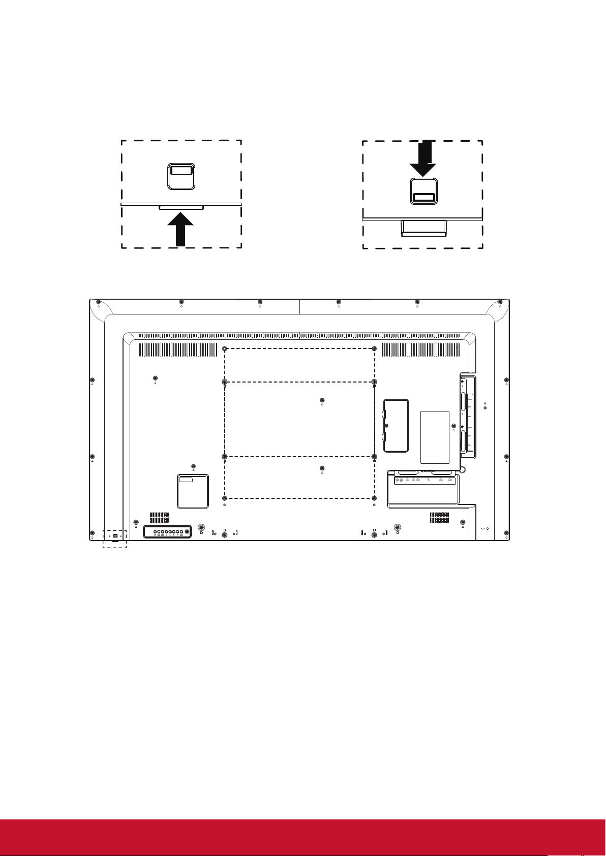
1.4. Mounting on a Wall
To mount this display to a wall, you will have to obtain a standard wall-mounting kit (commercially available).
We recommend using a mounting interface that complies with UL1678 standard in North America.
Protective Sheet
VESA Grid
Table
1. Lay a protective sheet on a table, which was wrapped around the display when it was packaged, beneath
the screen surface so as not to scratch the screen face.
2. Ensure you have all accessories for mounting this display (wall mount, ceiling mount, table stand, etc)
3. Follow the instructions that come with the base mounting kit. Failure to follow correct mounting
procedures could result in damage to the equipment or injury to the user or installer. Product warranty
does not cover damage caused by improper installation.
4. For the wall-mounting kit, use M6 mounting screws (having a length 10 mm longer than the thickness of
the mounting bracket) and tighten them securely.
5. Unit without base weight= 12.6 Kg.The equipment and its associated mounting means still remain secure
during the test. For use only with UL Listed Wall Mount Bracket with minimum weight/load:
12.6 Kg.
6. Por trait is not allowed.
1.4.1. VESA Grid
Model Vesa Grid
CDE5010 400(H) x 400(V)mm
Caution:
To prevent the display from falling:
• For wall or ceiling installation, we recommend installing the display with metal brackets which are
commercially available. For detailed installation instructions, refer to the guide received with the
respective bracket.
• To lessen the probability of injury and damage resulting from fall of the display in case of earthquake or
other natural disaster, be sure to consult the bracket manufacturer for installation location.
2
Page 12
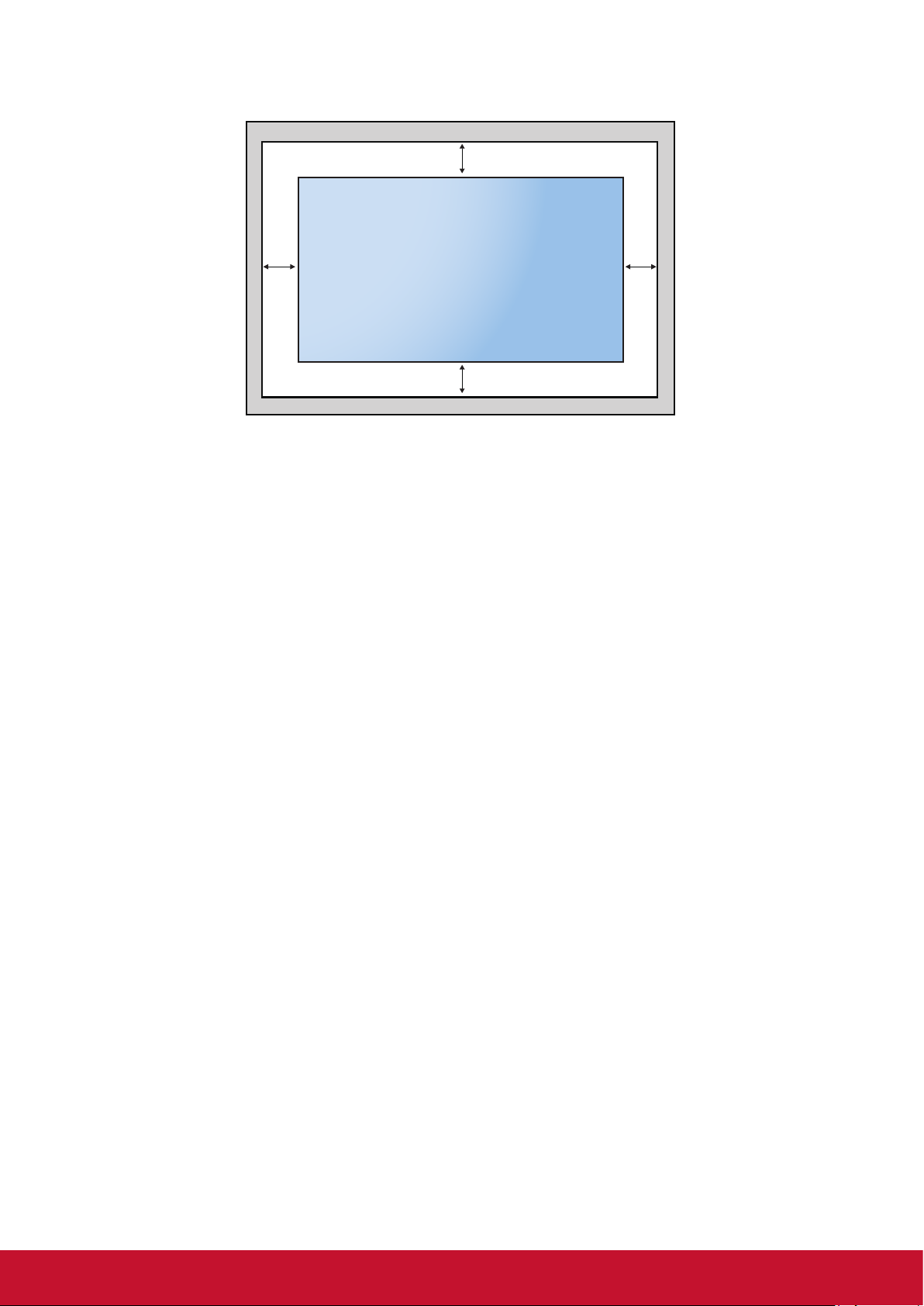
Ventilation Requirements for enclosure locating
To allow heat to disperse, leave space between surrounding objects as shown in the diagram below.
100 mm
100 mm 100 mm
100 mm
NOTES:
When installing the display on a wall, proper installation. We accept no liability for installations not performed
by a professional technician.
3
Page 13
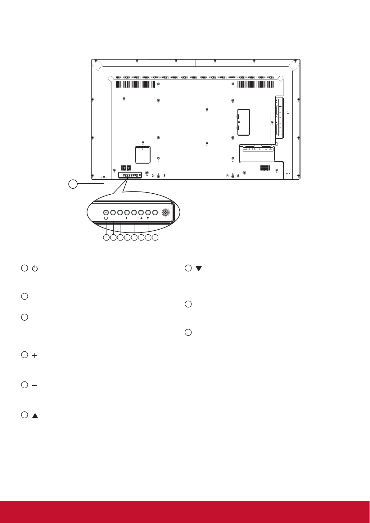
2. Parts and Functions
1 2 3 4 5 6 7 8
MUTE INPUT MENU
2.1. Control Panel
9
1
[ ] button
Use this button to turn the display on or put the
display to standby.
2
[MUTE] button
Switch the audio mute ON/OFF.
3
[INPUT] button
Choose the input source.
• Used as [OK] button in the On-Screen-Display
menu.
4
[ ] button
• Increase the volume
• Enter into submenu while OSD menu is on
5
[ ] button
• Decrease the volume
• Back
6
[ ] button
to previous menu while OSD menu is on
• Move the highlight bar up to adjust the selected
item while OSD menu is on
• Increas
e the adjustment while adjust value.
7
[ ] button
• Move the highlight bar down to adjust the selected item
while OSD menu is on.
• Decre
8
[MENU] button
ase the adjustment while adjust value.
Return to previous menu while OSD menu is on, or
to activate the OSD menu when OSD menu is o.
9
Remote control sensor and power status
indicator
• Receives command signals from the remote control.
• Indicates the operating status of the display without
OPS:
- Lights green when the display is turned on
- Lights red when the display is in standby mode
- When {SCHEDULE} is enabled, the light blinks green
and red
- If the light blinks red, it indicates that a failure has
been detected
- Lights off when the main power of the display is
turned o
* Using IR sensor cable for better remote control performance.
(Please refer to the instructions of 3.5)
4
Page 14
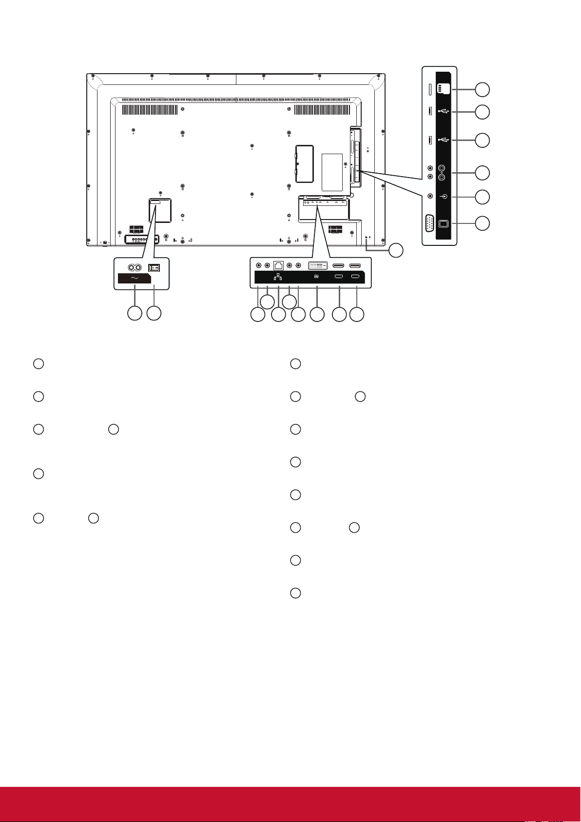
2.2. Input/Output Terminals
1 2
1
AC IN
AC power input from the wall outlet.
RS232
RS232
OUT
IN
4 6
3 5
IR-IN IR-OUT
RJ45
DVI IN
7 98 10
8
DVI-D IN
DVI-D video input.
HDMI 1 IN
HDMI 2 IN
17
MICRO SD
USB 3.0
5V/0.9A
USB 2.0
5V/0.5A
PC LINE IN
VGA IN
AUDIO OUT
16
15
14
13
12
11
2
MAIN POWER SWITCH
Switch the main power on/o.
3
RS232 OUT / 4 RS232 IN
RS232C network output / input for the loop-through
function.
5
RJ-45
LAN control function for the use of remote control
signal from control center.
6
IR OUT / 7 IR IN
IR signal output /input for the loop-through function.
NOTES:
• This display’s remote control sensor will stop
working if the jack [IR IN] is connected.
• To remotely control your A/V device via this
display, refer to page 14 for or IR Pass Through
connection.
9
HDMI1 IN / 10 HDMI2 IN
HDMI video/audio input.
11
VGA IN (D-Sub)
VGA video input.
12
PC LINE IN
Audio input from VGA source (3.5mm stereo phone).
13
AUDIO OUT
Audio output to external AV device.
14
USB 2.0 / 15 USB 3.0 PORT
Connect your USB storage device
16
MICRO SD CARD
Connect your MICRO SD CARD
17
Security LOCK
Used for security and theft prevention.
5
Page 15
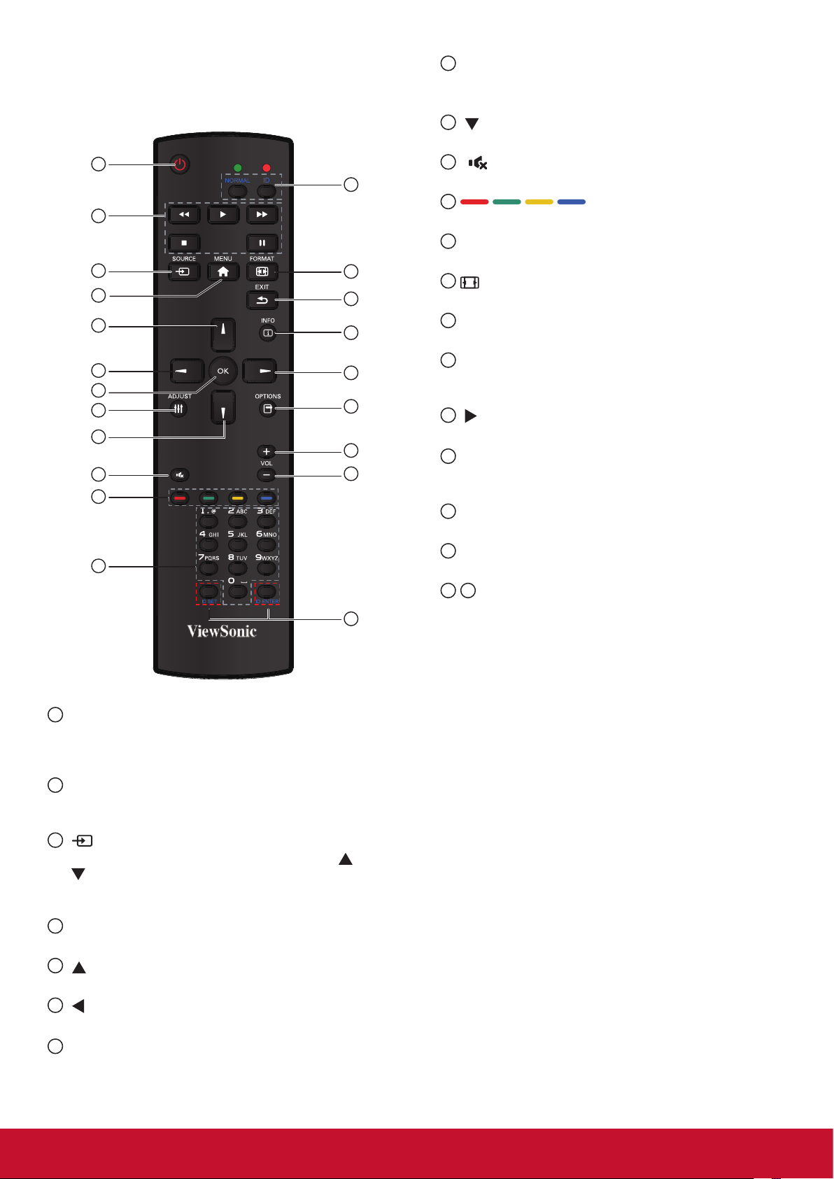
2.3. Remote Control
2.3.1. General functions
1
2
3
4
5
6
7
8
9
10
11
12
20
13
14
15
16
17
18
19
21
8
[ADJUST] button
Press to run the Auto Adjust function.
NOTE: This button is functional for VGA input only.
9
[ ] button
Press to move the se
10
[ ] MUTE button
tion down in OSD menu.
lec
Press to turn the mute function on/o.
11
COLOR buttons
Choose tasks or options.(for Media Input only).
12
[NUMERIC] buttons
Enter text for network setting.
13
Format button
Press to switch screen aspect ratio.
14
[EXIT] button
Press to turn back to the previous OSD menu.
15
[INFO] button
Press to turn on/o the information OSD displayed
on the upper right corner of the screen.
16
[ ] button
Press to increase the value in OSD menu.
17
[OPTION] button
Access currently available options, picture and
sound menus (for Media Input only).
18
[+] Volume up button
Press to increase the audio output level.
19
[-] Volume down button
Press to decrease the audio output level.
20 21
[ID SET] button
If a single large- screen matrix (video wall) is
created, set ID key to control each dispaly.
1
[POWER] button
Press to switch on the display from standby mode.
Press again to turn it o and back into standby
mode.
2
[PLAY] button
Control playback of media les (for Media Input
only).
3
[ SOURCE] button
Press to toggle Video Source Menu. Press [
[ ] button to select one of the video sources
among DVI-D, VGA, HDMI1, HDMI2, Media Player,
Browser or PDF Player. Press [OK] button.
4
[MENU] button
Press to turn the OSD menu on/o.
5
[ ] button
Press to move the selection up in OSD menu.
6
[ ] button
Press to decrease the value in OSD menu.
7
[OK] button
Press to activate the setting inside the OSD menu.
] or
ID Remote Control:
You can set the remote control ID when you want to use
this remote control on one of several dierent displays.
Press [ID] button. The red LED blinks twice.
1. Press [ID SET] button for more than 1 second to
enter the ID ode. The red LED lights up.
Press the [ID SET] button again will exit the ID
Mode. The red LED lights o.
Press the digit number [0] ~ [9] to select the display
you want to control.
For example: press [0] and [1] for display No.1,
press [1] and [1] for display No. 11.
The numbers available are from [01] ~[255].
2. Not pressing any button within 10 seconds will exit
the ID Mode.
3. If an error pressing of buttons other than the digits
occurred, wait 1 second after the red LED lights
o and then lights up again, then press the correct
digits again.
4. Press [ID ENTER] button to conrm. The red LED
blinks twice and then lights o.
NOTE:
• Press [NORMAL] button. The green LED blinks
twice, indicating the display is in normal operation.
It is ncecssary to set up the ID number for each
display before selecting its ID number.
6
Page 16
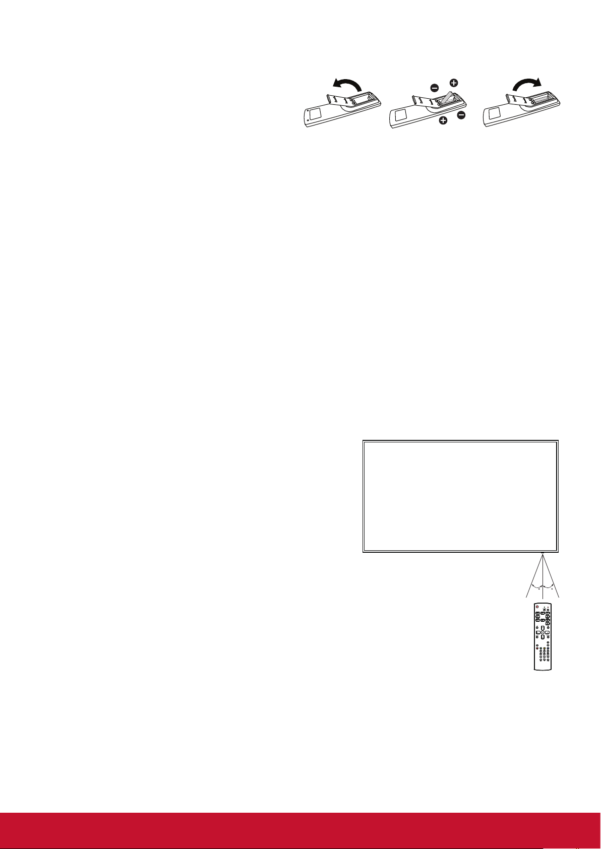
2.3.2. Inserting batteries in the remote control
The remote control is powered by two 1.5V AAA batteries.
To install or replace batteries:
1. Press and then slide the cover to open it.
2. Align the batteries according to the (+) and (–)
indications inside the battery compartment.
3. Replace the cover.
Caution:
The incorrect use of batteries can result in leaks or bursting. Be sure to follow these instructions:
• Place “AAA” batteries matching the (+) and (–) signs on each battery to the (+) and (–) signs of the
battery compartment.
• Do not mix battery types.
• Do not combine new batteries with used ones. It causes shorter life or leakage of batteries.
• Remove the dead batteries immediately to prevent them from liquid leaking in the battery compartment.
Don’t touch exposed battery acid, as it can damage your skin.
NOTE: If you do not intend to use the remote control for a long period, remove the batteries.
2.3.3. Handling the remote control
• Do not subject to strong shock.
• Do not allow water or other liquid to splash the remote control. If the remote control gets wet, wipe it dry
immediately.
• Avoid exposure to heat and steam.
• Other than to install the batteries, do not open the remote control.
2.3.4. Operating range of the remote control
Point the front of the remote control toward this display’s
remote control sensor when pressing a button.
Use the remote control within a distance of less than
8m/26ft from this display’s sensor, and a horizontal and
vertical angle of less than 30 degrees.
NOTE: The remote control may not function properly when
the remote control sensor on this display is under
direct sunlight or strong illumination, or when there is
an obstacle in the path of signal transmission.
3030
7
Page 17
2.4. Using of Remote sensor and power indicator
1. Push down the lens to have better remote control performance and easy to observe the light information
of power status..
2. Push up the lens before mounting the display for video wall application.
3. Pull/Push the lens until hearing the click sound.
Push up to collapse the lens Push down to extend the lens
8
Page 18
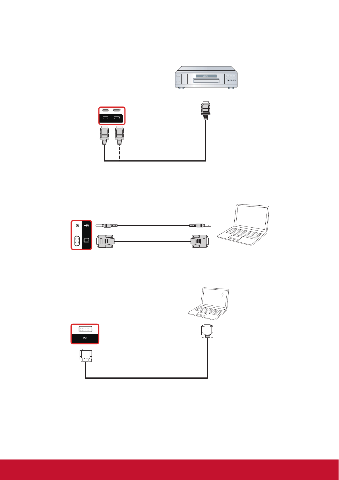
3. Connecting External Equipment
HDMI 1 IN HDMI 2 IN
DVD / VCR / VCD
HDMI 1 IN HDMI 2 IN
HDMI Out
[HDMI IN]
DVD / VCR / VCD
HDMI 1 IN HDMI 2 IN
HDMI Out
[HDMI IN]
PC
PC LINE IN
VGA IN
[VGA IN]
[VGA AUDIO IN]
VG A Out
D-Sub 15 pin
Audio Out
3.1. Connecting External Equipment (DVD/VCR/VCD)
3.1.1. Using HDMI video input
DVD / VCR / VCD
[HDMI IN]
3.2. Connecting a PC
HDMI Out
3.2.1. Using VGA input
3.2.2. Using DVI input
PC LINE IN
VGA IN
DVI IN
[VGA AUDIO IN]
[VGA IN]
Audio Out
VG A Out
D-Sub 15 pin
PC
PC
DVI Out
[DVI IN]
9
Page 19
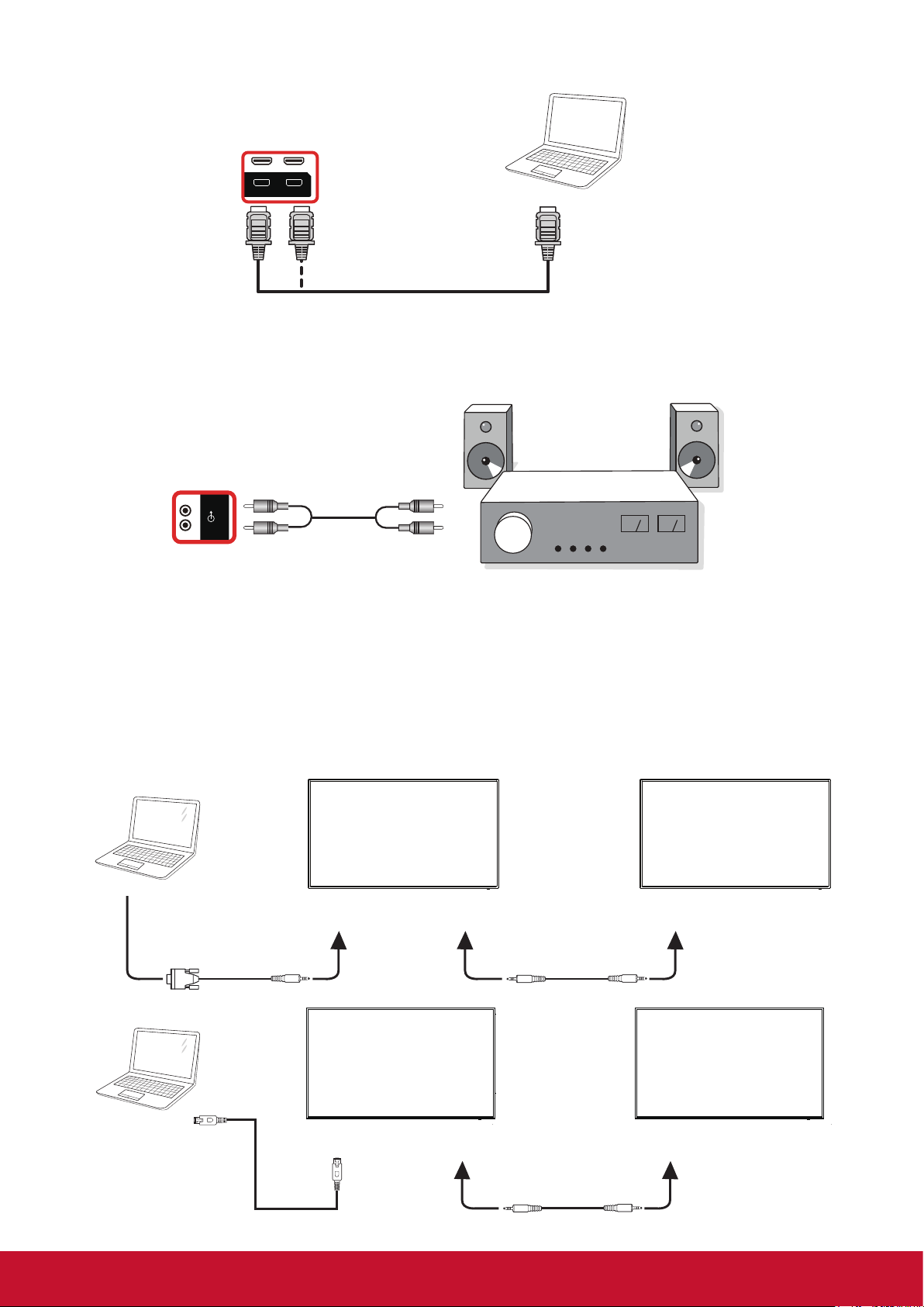
3.2.3. Using HDMI input
HDMI 1 IN HDMI 2 IN
PC
HDMI 1 IN HDMI 2 IN
HDMI Out
[HDMI IN]
PC
HDMI 1 IN HDMI 2 IN
HDMI Out
[HDMI IN]
AUDIO OUT
Stereo Amplifier
[AUDIO OUT] Audio In
[HDMI IN]
3.3. Connecting Audio Equipment
3.3.1. Connecting an external audio device
[AUDIO OUT] Audio In
PC
HDMI Out
AUDIO OUT
Stereo Amplifier
3.4. Connecting Multiple Displays in a Daisy-chain Configuration
You can interconnect multiple displays to create a daisy-chain conguration for applications such as a
menu board.
3.4.1. Display control connection
Connect the [RS232C OUT] connector of DISPLAY 1 to the [RS232C IN] connector of DISPLAY 2.
DISPLAY 1
DISPLAY 2
PC
[RS-232C]
[RS-232C IN]
[RS-232C OUT] [RS-232C IN]
PC
[RJ-45]
DISPLAY 1
[RJ-45] [RS-232C OUT] [RS-232C IN]
10
DISPLAY 2
Page 20
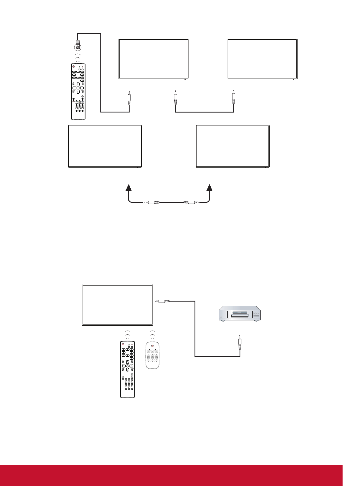
3.5. IR Pass-through Connection
DISPLAY 1
DISPLAY 2
[RJ-45] [RS-232C OUT] [RS-232C IN]
[RJ-45]
External
IR Receiver
DISPLAY 1
DISPLAY2
[IR IN]
DISPLAY 1 DISPLAY 2
[RS-232C OUT] [RS-232C IN]
[IR OUT]
[IR IN]
NOTE:
1. This display’s remote control sensor will stop working if the [IR IN] is connected.
2. IR loop through connection can suppor t up to 9 displays.
3. IR in daisy chain via RS232 connection can suppor t up to 9 displays.
3.6. IR Pass-through Connection
[IR OUT]
DVD / VCR / VCD
[IR IN]
(DVD / VCR / VCD)
Remote Control
11
Page 21
4. Operation
NOTE: The control button described in this section
is mainly on the remote control unless
specied otherwise.
4.1. Start-up and initial Setting
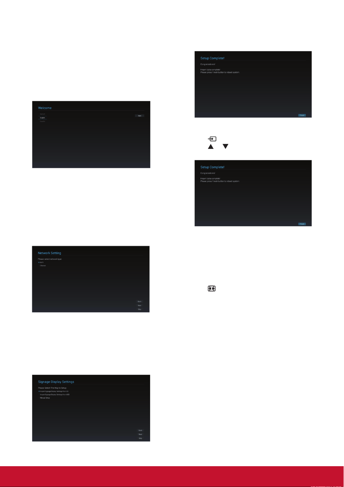
4.1.1. Welcome
Select your language and tap “Start”.
4.1.2. Network Setting
Tape “Next” button to next page and it will show.
1. Connection Type : DHCP / Static IP
2. IP Address
3. Netmask
4. DNS Address
5. Gateway
You also can tape “Skip” to congure later
4.1.3. Signage Display Settings
User can import the setting le from SD, USB or
manual setting. User also can tape “Skip”.
Note: The setting le should be put on viewsonic
folder in SD or USB and the le name is settings.
db.
4.1.4. Setup Complete
The initial settings are completed. Press “Finish”
and display will reboot automatically.
4.2. Watch the Connected Video Source
1. Press
2. Press
press OK button.
SOURCE button.
or button to select a device, then
4.3. Change Picture Format
You can change the picture format to suit the video
source. Each video source has its available picture
formats.
The available picture formats depend on the video
source:
1. Press
format.
• PC mode: {Full} / {4:3} / {Real} / {21:9}/
{Custom}.
• Video mode: {Full} / {4:3} / {Real} / {21:9}/
{Custom}
FORMAT button to choose a picture
12
Page 22
4.4. Media Player
You can play videos, photos, and music on your
display from:
• USB Multimedia Player for Scheduled Playback
of Videos, Photos and Music.
• A USB device connected to this display.
Media Player page has three items: {Play},
{Compose} and {Settings}.
• {Play} : select playlist to play.
• {Compose}: edit playlist.
• {Settings}: setting play properties.
1. Select {Play} on this page, rst you should
choose one playlist to play between FILE 1 and
FILE 7. The pencil icon means the playlist is
non-empty.
2. Select {Compose} on this page, rst you should
choose one playlist to edit between FILE 1 and
FILE 7. The pencil icon means the playlist is
non-empty.
B. You could edit or delete a non-empty playlist,
just choose the desired playlist which is with
pencil icon.
C. Once you start to edit a playlist, you will see
below screen.
Source - les in storage.
Playlist – les in playlist.
There are 4 icons which map to the keys of
remote controller.
Option key – launch slidebar
Play key – play media le.
Info key – show media info.
Ok key – select/unselect le.
In the slidebar, it helps you to do the following:
• select all : select all storage les.
• delete all : delete all playlist les.
• add/remove : update playlist from source.
• sort : sort playlist.
• save/abort : save or abort playlist.
• back : return.
A. If an empty playlist is chosen, the app will guide
you to select the media source.
All media les should be placed in / viewsonic /
of root directory.
For example,
• videos in /root/viewsonic/video/
• photos in /root/ viewsonic /photo/
• music in /root/ viewsonic /music/
13
Page 23

D. if you choose “Sort” in the slidebar, you can
change the order of les one by one.
E. Press info key after you choose desired le,
you will get the detail information.
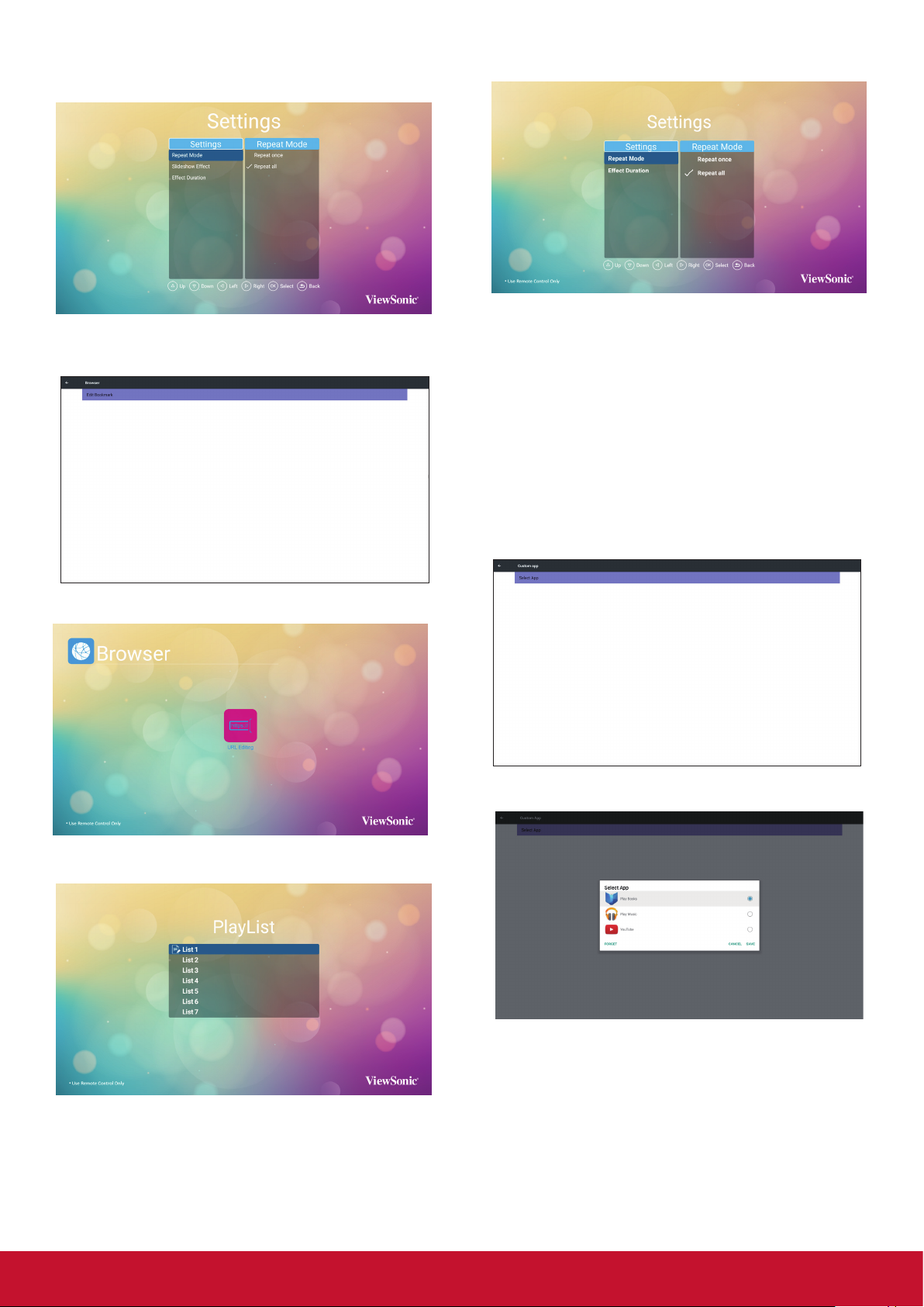
4.5. Web Browser
You can save the web link and easy to browse the
web site.
Browser page has one item: {Settings}. Press
{Settings} then enter next page.
1. Users can choose 1~7. Press any one will show
a dialog.
F. Press play key after you choose desired le,
you will plays the media le directly.
G. If you make a playlist with all images les,
before saving, the app will ask you if you want
to have background music while slideshow
playing.
3. Select {Settings} on this page, this page has
three parts, {Repeat Mode}, {Slideshow
Eect} and {EectDuration}.
• {Repeat Mode} : play mode.
• {SlideshowEect} : photo slideshow eect.
• {EectDuration} : photo e
ect duration.
Enter URL and press OK then data will save on
List
14
Page 24
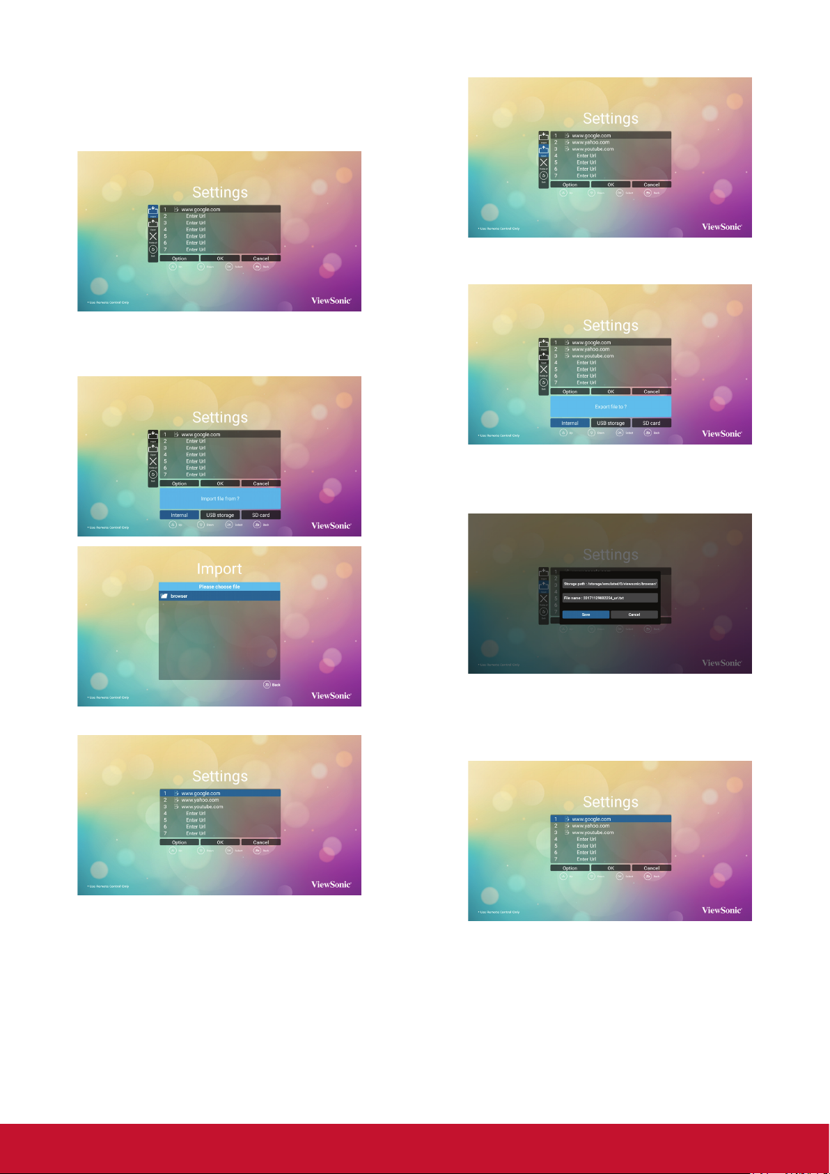
2. Press “Option” then left side will pop up a list
Import : Import url list le
Export : Export url list le
Delete all : Delete all url record on right side
Back : left side list will be close.
A. Import
Click Import, you can select URL le from Internal,
USB storage or SD card.
B. Export
Click Export, you can select Internal, USB storage
or SD card for export le to.
Dialog shows path le will be saved and le’s
name. Press “save” button then URLs on list will
be saved.
After URL le selected, URL will show on list.
3. On URL list page, if you select non-empty item,
it will show a dialog to ask edit or play url. If
press “Edit”, it will show edit url dialog, if press
“Play”, it will show web page of item’s url.
15
Page 25
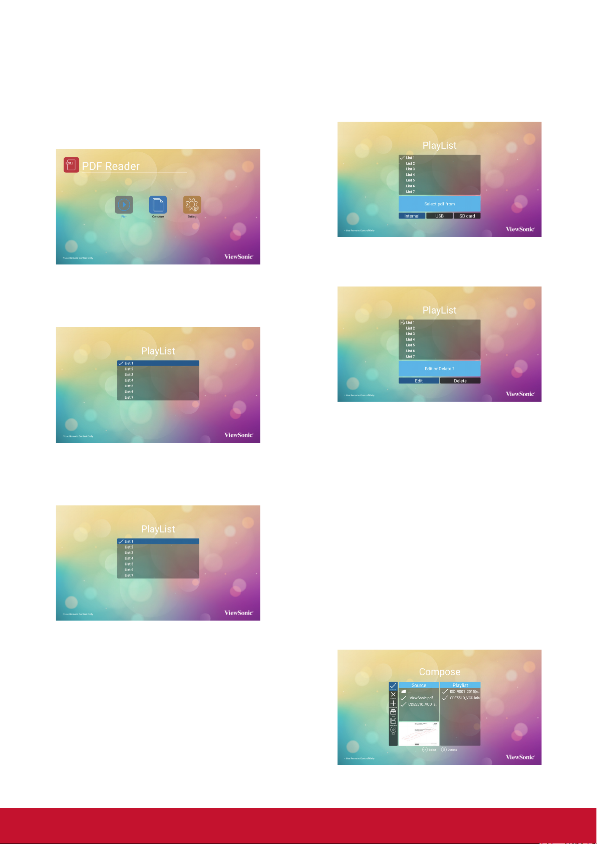
4.6. PDF Reader
You can play PDF le on your display from internal,
USB or SD card.
This page has three items: {Play}, {Compose} and
{Settings}.
• {Play}: select playlist to play.
• {Compose}: edit playlist.
• {Settings}: setting play properties.
1. Select {Play} on this page, rst you should
choose one playlist to play between FILE 1 and
FILE 7. The pencil icon means the playlist is
non-empty.
A. If an empty playlist is chosen, the app will guide
you to select the media source.
All media les should be placed in /viewsonic/
of root directory.
For example,
• pdfs in /root/viewsonic/pdf/
B. You could edit or delete a non-empty playlist,
just choose the desired playlist which is with
pencil icon.
2. Select {Compose} on this page, rst you should
choose one playlist to edit between FILE 1 and
FILE 7. The pencil icon means the playlist is
non-empty.
C. Once you start to edit a playlist, you will see
below screen.
Source - les in storage.
Playlist – les in playlist.
There are 4 icons which map to the keys of
remote controller.
Option key – launch slidebar
Play key – play media le.
Info key – show media info.
Ok key – select/unselect le.
In the slidebar, it helps you to do the following:
- select all : select all storage les.
- delete all : delete all playlist les.
- add/remove : update playlist from source.
- sort : sort playlist.
- save/abort : save or abort playlist.
- back : return.
16
Page 26
Select “Sort” in the slidebar, you can change the
order of les one by one.
3. Select {Settings} on this page, this page
has two parts, {Repeat Mode} and {Eect
Duration}.
• {Repeat Mode} : play mode.
• {EectDuration} : photo eect duration.
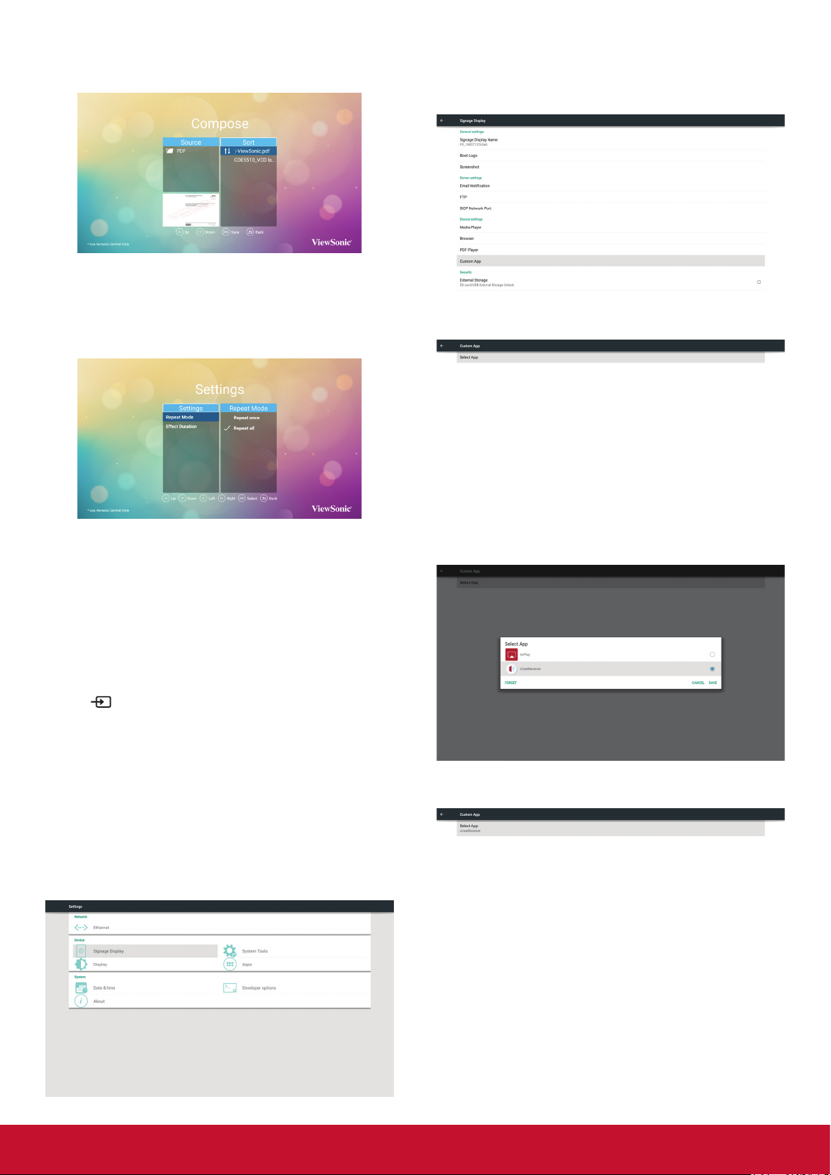
2. Select Custom app will show the installed APK.
CDE model pre-install the vCastReceiver APK
inside.
3. Press Select App to show the APK list.
4.7. Custom App
User can set up the application for Customer
Source
Note:
(1) Only display User Installed app.
(2) Will not show up system pre-install app.
4.7.1. OSD Menu operation:
Press
If set up customer APK, PD will open customer
app when switch source to Customer mode.
If no set up customer APK, PD will show Black
screen when switch source to Customer mode.
4.7.2. Set Custom App
Select custom app from source setting.
1. Entry Signage Display in Admin Mode (Refer
section 4.7 & 4.7.3)
SOURCE button and select Custom.
4. Select vCastReceiver and press Save.
5. vCastReceiver APK name will show on Select
App.
6. Exit admin mode and press custom input
source. vCastReceiver will run on screen.
17
Page 27

4.8. vCastReceiver
ViewBoard Cast is the built-in wireless screen
sharing receiver app within ViewBoard that allow
users to cast in their presentation content, including mirroring screen content, images, videos, and
audios. Before use ViewBoard Cast function,
please be noted that proper network infrastructure
setting is required.
ViewBoard Cast is the wireless peer to peer data
communication so that a proper ports setting is required.
3. Launch ViewBoard Cast and click the icon
number that shown on IFP.
4.8.2. Viewboard Cast sender from mobile
devices: iOS-based (iPhone, iPad) and
Android OS based phone/tablet
iOS
Step 1: Make sure your device is connected to the
same network with IFP.
Step 2: Enter password that shown on IFP.
• Ports :
- TCP: 56789, 25123, 8121, and 8000 ports
- UDP: 48689, 25123
• Port for activation:
- Port: 8001
[Remark] please be noted that screen sharing or
video casting in/out is highly defendant on the
each school’s or corporate’s IT network configuration and WiFi network bandwidth. The variation
might be cause from internal network speed, routing, WiFi configuration, and QoS setting. Please
consult your IT for related details.
4.8.1. Cast sender from Windows-based
devices, Macbook, and Chrome devices
Step 3: Slide up at the bottom enter the quick set
Open AirPlay.
Step 4: Select the device, then the iOS operate
interface will appear.
Android
Step 1: Make sure your device is connected to the
same network with IFP.
Step 2: Enter password that shown on IFP.
Step 3: Scan the QR code that shown on IFP to
download the client.
Step 4: Open the ViewBoard Cast client.
Mac, Windows and Chrome devices
1. Make sure your device is connected to the
same network with IFP.
2. Visit the address that shown on IFP to
download application.
18
Page 28
4.8.3. ViewBoard Cast out from mobile device
will support annotation function
Item Description
Toggle Click to hide or display tool bar
Home Click to return to home interface
5. Setting (Admin mode)
Press Menu 1 9 9 8 on remote control to enter
admin mode.
5.1. Setting
Main items:
(1) Ethernet
(2) Signage Display
(3) System Tools
(4) Display
(5) Apps
(6) Date & time
(7) Developer options
(8) About
Return
Folder
Screen
sharing
Touch Click to change to touch mode
Pen
Clear Click to clean all the elements
Camera
Click to return to previous operation
interface
Click to view or open mobile device
internal file
Click to share screen
(Android 5.0 above supported)
Click to make annotation in the picture
Click to change color or thickness
Click to use camera then send the
image to IFP50
5.2. Ethernet
Enable/Disable to turn on/o Ethernet
After enable Ethernet, the settings will show:
(1) Connection Type (Available connection
type: DHCP/Static IP)
A. DHCP
B. Static IP
C. IP Address
D. Netmask
E. DNS Address
F. Gateway
(2) Mac Address
19
Page 29

5.2.1. DHCP
DHCP mode:
(1) Cannot modify IP Address, Netmask, DNS
Address and Gateway.
(2) If connect successfully, it will display
current network conguration.
5.2.2. Static IP
In Static IP mode, user can input IP Address,
Netmask, DNS address and Gateway.
(4) Security
A. External Storage
5.3.1. General Settings
1. Signage Display Name
Set up PD name “PD_” + Ethernet Mac Address.
Note:
Input limitation:
(1) length: Max 36 characters
(2) format: no limit
Note:
IP address, netmask, DNS address and gateway
address input limitation.
(1)Format:
I. number 0-9
II. decimal point “.”
5.3. Signage Display
Divide into 4 groups: General Settings / Server
Settings / Source Settings / Security
(1) General Settings
A. Signage Display Name
B. Boot Logo
C. Screenshot
(2) Server Settings
A. Email Notication
B. FTP
C. SICP Network Port
(3) Source Settings
A. Media Player
B. Browser
C. PDF Player
D. Custom app
2. Boot Logo
1) Scalar OSD menu to control Android boot logo
enable/disable Scalar OSD menu operation
RCU: MENU -> Conguration2 -> Logo -> On/O/
User.
In user mode, user can choose their own boot logo
animation le.
Note:
(1) Boot animation le name: bootanimation.
zip
(2) Will pop-up a window for user to select
USB and SD card. No priority issue.
20
Page 30
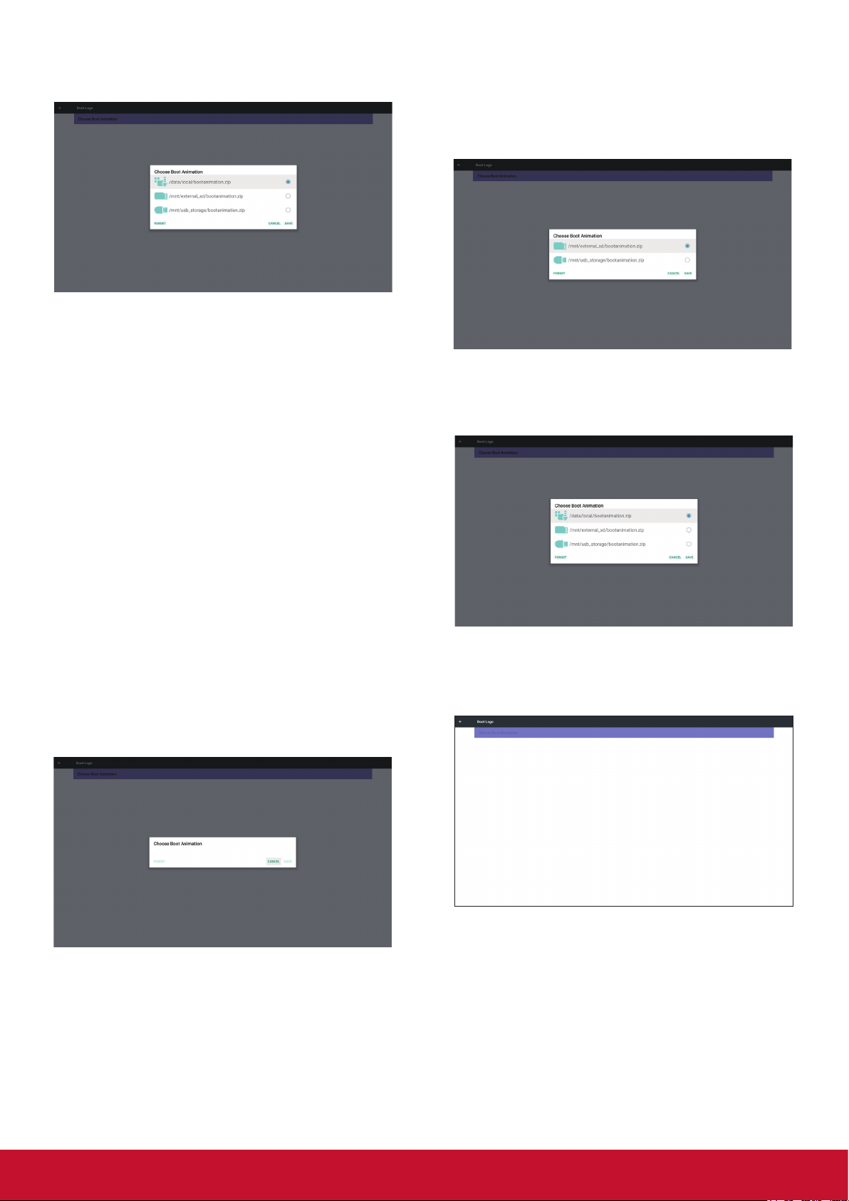
3) When boot logo selected, PD will check if there
is bootanimation. zip under USB and SD card.
Function introduction:
a. Option description
/data/local
Use customized boot animation le which is
copied from SD card or USB
/mnt/external_sd
Use boot animations le under SD card
/mnt/usb_storage
Use boot animations le under USB
b. Save
Press save key to save SD card or USB
bootanimation.zip to /data/
local and set it as boot logo.
c. Forget
Press Forget key to delete /data/local
bootanimation.zip and not show boot logo.
d. Cancel
Close dialogue w/o changes. Scenario
introduction:
Case 1
The user don’t settle customized boot logo. PD
does not nd any bootanimation.zip le under SD
and USB.The list will be blank. Save and Forget
button will be gray and useless.
Case 2
The users do not settle customized boot logo. PD
nd bootanimation.zip le under SD and USB.The
screen will show bootanimation.zip and select the
rst le automatically.
Case 3
The user settle customized boot logo, the screen
will show /data/ local/bootanimation.zip.
4) If OSD menu Logo item is On or O, the users
cannot choose boot animation in Android
settings.
3. Screenshot
Via Enable/Disable to control screenshot On/O.
After Enable, user can set screenshot timeslot
and save path.
Note:
Time slot of deletion and screenshot:
(1) Will delete picture at initial time 0 sec.
(2) Will screeshot at rst 40 sec.
(3) Media player, Browser, CMND & play, PDF
reader, Custom source are suppor ted.
21
Page 31

(4) Screenshot will not include video container
1) Inter val
Set up interval timeframe. 30 mins or 60 mins
3) End Time
Set up screenshot End time
Note:
(1) If no End time, the screen will show current
time automatically
(2) Star t time cannot be newer than End time.
It will show error toast.
4) Repeat
Set screenshot repeat cycle. User can choose
screenshot time frame. (Multiple selection)
2) Start Time
Set up screenshot start time.
Note:
(1) If no star t time, the screen will show
current time automatically
(2) Just press Back key to exit dialog for Set
up
(3) Start time cannot be newer than End time.
It will show Error toast.
5) Save to
Set up screenshot save path. Internal storage, SD
card or USB storage.)
Note:
picture storage path
(1) In root of internal storage/usb storage/sd
card, PD will create folder automatically.
(2) The picture will save to ViewSonic/
Screenshot/.
22
Page 32

6) Purge Screenshots
Set up purge timeframe. One day or One week.
(7) Send screenshots via email
After check this item, it will send screenshot to
email of administrator
Please refer to 6.2.1 Email notication
Note:
Please conrm Email setting is done.
5.3.2. Server Settings
1. Email Notication
Via Enable/Disable to control Email On/O)
After Enable, user can set up Email notication
conguration.
1) SMTP (Set SMTP conguration)
User can set Gmail account or other mail account.
User can select other mail account and set up
SMTP server, Security type and por t item
Note
Password input limitation
(1) Length: 6-20 characters
(2) Format: no limit
(3) unavailable por t: 5000
Gmail safety setting
If Gmail is not working when setting is complete,
please test Gmail account via PC and link below
URL
And conrm “Access for less secure apps” item is
Turn On
Yahoo Email Security Setting
If Yahoo Email is not working when setting
complete, please conrm “Allow apps that use less
secure sign in” item is enabled.
23
Page 33
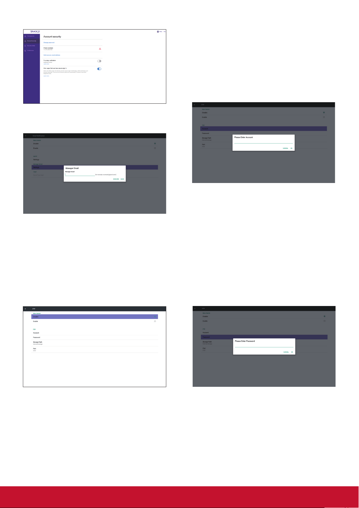
2) Manager Email
Set up Receiver mail account
1) Account
Set up FTP account
Note:
Input limitation
(1) Length: 4-20 characters
(2) Format:
I. English a-z and A-Z
II. Number 0-9
2) Password
Set up FTP password.
3) Test
Send Test Mail
To test Gmail account receive/send function. Note
(1) When Email is Disable, “Send Test Mail
Button” button will gray out
2. FTP
Via Enable/Disable to control FTP On/O. After set
up, PD can share
FTP les.
Note:
Input limitation
(1) Length: 6-20 characters
(2) Format:
I. English a-z and A-Z
II. Number 0-9
FTP password display
(1) Will show “*” symbol to instead password if
set up password via remote control.
(2) After set up, the password text will show
as “*” symbol. Before password input:
24
Page 34
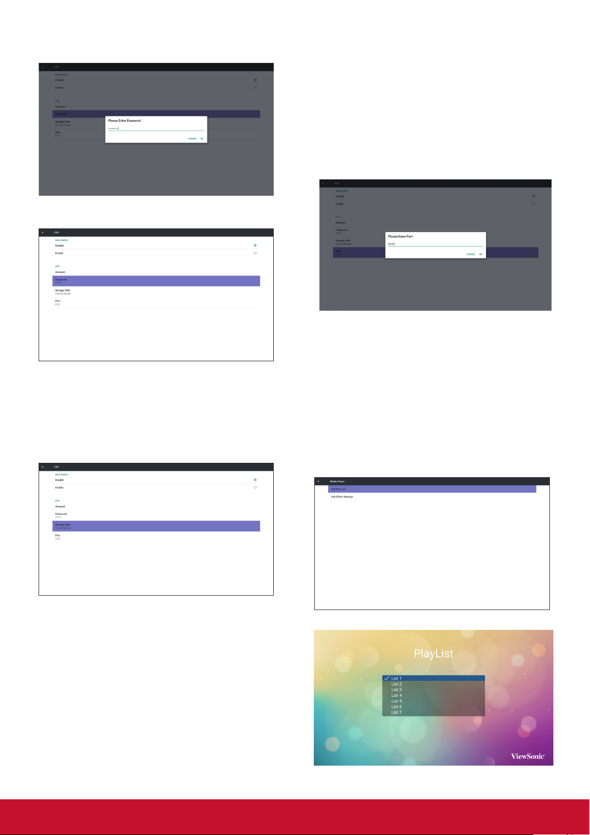
After password input:
Set up completed screen:
5) Port
Set up FTP por t number. Default: 2121
Note:
Input limitation
(1) Length: Max 5 characters
(2) Range: 1024 ~ 65535
(3) Format: Number 0-9
(4) Unavailable por t: 5000
(5) The por t number must more than 1024
3. SICP Network Port
Change SICP Network Port.
3) Storage Path
Show default path: Internal storage
Note:
Can only display Internal storage, cannot be
modied.(Only show path)
4) Will show Server is unbinded if Remote control
server feedback unbinded status.
Note:
(1) Range: 1025-65535
(2) unavailable port: 8000 / 9988 / 15220 /
28123 / 28124
5.3.3. Source Settings
1. Media Player
Can Edit Media Player play list and eect settings.
(1) Open Media Player Player List edit page.
25
Page 35
(2) Open Media Player slideshow eect edit
page.
(2) Open PDF Player eect edit page.
2. Browser
Can edit Bookmark conguration.
Open Browser setting page.
4. Custom App
User can set up the application for Customer
Source. Note
(1) Only display User Installed app.
(2) Will not show up system pre-install app.
Scalar OSD menu operation
RCU: Source -> Custom
If set up customer APK, PD will open customer
app when switch source to Customer mode.
If no set up customer APK, PD will show Black
screen when switch source to Customer mode.
3. PDF Player
(1) Open PDF Player Player List edit page.
Function introduction
(1) Save
Select App and press Save key to save it.
(2) Forget
Press Forget key to clean previous stored
data
(3) Cancel
No change, close window directly
If no customer installed apk, the list will be
blank.
26
Page 36
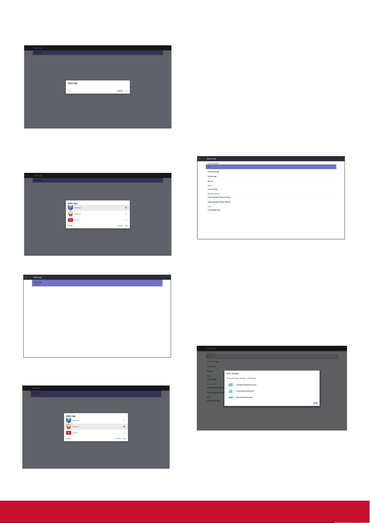
No option for choose. Save and Forget key
will be gray and unavailable.
User can select customer installed apk in list
No setup Custom App
Screen will show available apps and focus on rst
app item automatically.
5.3.4. Security
1. External Storage
Enable: SD card/USB External Storage Lock.
Disable: SD card/USB External Storage Unlock.
Note:
Must re-plug SD card/USB External Storage after
unlock the external storage.
5.4. System Tools
System tools 4 main functions:
(1) Clear Storage
(2) Reset
(3) Import & Export
(4) Clone
After setup, it will show App name
Case2. Setup Custom App. (there is a checked
circle on right)
5.4.1. Clear Storage
The purpose is to clear all data in viewsonic
folders. Divided into 4 mode:
(1) Clear all viewsonic folders
(2) Only clear viewsonic folder under Internal
storage.
(3) Only clear viewsonic folder under USB
storage.
(4) Only clear viewsonic folder under SD card.
Pop-up the window to display all folders which can
be clear.
27
Page 37
5.4.2. Reset
Factory Reset can recover to Factory default
settings.
Note:
If no viewsonic folder exists in USB or SD card, it
will be created automatically.
List all available storage (internal/SD/USB)
Press OK to execute Reset function automatically.
5.4.3. Import & Export
The function of Impor t & Export PD settins.
Notes.
(1) Settings.db (Saved le name: settings.db)
(2) Will save to viewsonic folder in storage
5.4.3.1 Export Signage Display Settings
Will export to viewsonic folder under USB or SD
card
(1) Export settings.db. Include OSD setting,
Android settings but “Signage Display
Name” and “Boot Logo”
(2) Export 3rd party apk to viewsonic/app/
5.4.3.2 Import Signage Display Settings
Impor t settings.db from viewsonic folder under
USB or SD card.
(1) Import settings.db. Include OSD setting,
Android settings but “Signage Display
Name” and “Boot Logo”
(2) Auto install 3rd par ty apk from viewsonic/
app/List all available storage (Internal/SD/
USB)
Show notication dialog before database import
5.4.4. Clone
Clone media le from Internal, SD or USB
viewsonic folder.
1. The cloned folder name under viewsonic folder
(1) viewsonic/photo
(2) viewsonic/music
(3) viewsonic/video
(4) viewsonic/pdf
(5) viewsonic/browser
28
Page 38

2. Clone Source
(1) Internal storage
(a) check FTP
(b) check /viewsonic/
(2) SD / USB
Files under root
3. Target Location
(1) Internal storage
Save to /viewsonic/
(2) SD / USB
Save to root
5.7. Date & time
Via Scalar OSD menu to control Auto Time On/O.
Note:
Add new NTP server to display current ser ver IP.
5.8. Developer options
Android developer options
5.5. Display
User can modify the font size, can choose: Small/
Normal/Large/Huge
5.6. Apps
Display applications information.
Note
(1) User options key on RCU to show setting
option.
5.9. About
Main info in About:
(1) System updates
(2) Legal information
(3) Android version
(4) Kernel version
(5) Build number
29
Page 39

5.9.1. System updates
1 2 3 4 5 6 7 8
MUTE INPUT MENU
Will automatically search update.zip in USB. Will
be shown in list for user selection if found
Note:
(1) Only support Android Full image.
(2) le name should be update.zip.
(3) the le should be located in root of storage.
After select update.zip le, PD will restart and start
to update.
6. OSD Menu
An overall view of the On-Screen Display (OSD)
structure is shown below. You can use it as a
reference for further adjusting your display.
Navigating the OSD menu using the remote
control:
1. Press the [
] MENU button to display the OSD
menu.
2. Press [
] [ ] [ ] or [ ] button to select its menu
item or to adjust its value. Press OK button to
conrm.
3. Press [
] EXIT button to go back to the
previous menu layer.
4. Press [
] MENU button to exit the OSD menu.
Navigating the OSD menu using the display’s
control buttons:
9
1. Press the MENU button to display the OSD
menu.
2. Press the [
] [ ] [ ] or [ ] to select menu item
or adjust its value.
3. Press [INPUT] button to conrm menu selection
and enter its submenu.
4. Press MENU to conrm menu selection and
enter its submenu.
30
Page 40

6.1. Settings
6.1.1. Picture menu
Picture
Screen
Audio
Configuration 1
Configuration 2
Advanced option
Brightness (Picture)
Adjust the overall image and background screen
brightness(backlight).
Brightness
Contrast
Sharpness
Black level
Tint
Color
Noise reduction
Gamma selection
Color temperature
Color control
Smart power
Overscan
90
50
20
50
50
55
Medium
Native
Native
Action
Off
Off
Gamma selection
Select a display gamma. It’s refer to the brightness
performance cur ve of signal input. Choose from
{Native} / {2.2} / {2.4} / {s gamma} / {D-image}.
NOTE: sRGB picture mode is standard and cannot
be changed.
Color temperature
It is used to adjust the color temperature.
The image becomes reddish as the color
temperature decreases, and becomes bluish as
the color temperature increases.
CCT 10000º K 9300 º K 7500 º K 6500 º K 5000 º K 4000 º K 3000 º K
0.279 ±
X
0.292 ±
Y
0.030
0.030
0.283 ±
0.030
0.298 ±
0.030
0.299 ±
0.030
0.315 ±
0.030
0.313 ±
0.030
0.329 ±
0.030
0.346±
0.030
0.359±
0.030
0.382±
0.030
0.384±
0.030
0.440±
0.030
0.403±
0.030
Contrast
Adjust the image contrast ratio for the input signal.
Sharpness
This function is digitally capable to keep crisp
image at any timings.
It is adjustable to get a distinct image or a soft
one as you prefer and set independently for each
picture mode.
Black level
Adjust the image brightness for the background.
NOTE: sRGB picture mode is standard and cannot
be changed.
Tint (Hue)
Adjust the tint of the screen.
Press + button the esh tone color becomes
greenish. Press - button the esh tone color
becomes purplish.
NOTE:VIDEO mode only.
Color control
The color levels of red, green, and blue are
adjusted by the color bars. R: Red gain, G: Green
gain, B: Blue gain.
Smart power
Smar t Power control is not relative to brightness
control:
1. Initial setting Brigthness
70 (in the range from 0-100)
Power consumption 70% of maximum power
consumption
2. Smart Power
OFF: no adaptation
MEDIUM: 80% of power consumption relative
to current settings
HIGH: 65% of power consumption relative to
current settings
Overscan
Change the display area of the image. ON: Set to
display area about 95%. OFF: Set to display area
about 100%.
Color (Saturation)
Adjust the color of the screen.
Press + button to increase color depth. Press -
button to decrease color depth.
NOTE: VIDEO mode only
Noise Reduction
Adjust the noise reduction level.
Picture reset
Reset all settings in the Picture menu.
Select “Yes” and press “SET” button to restore to
factory preset data. Press “EXIT” button to cancel
and then return to the previous menu.
31
Page 41

6.1.2. Screen menu
Picture
Screen
Audio
Configuration 1
Configuration 2
Advanced option
H position
V position
Clock
Zoom mode
Custom zoom
Auto adjust
Screen reset
50
50
97
Full
Action
Action
Action
H position
Control Horizontal Image position within the
display area of the LCD.
Press + button to move screen to right.
Press - button to move screen to left.
NOTE:VGA input only.
Full
This mode restores the correct
proportions of pictures transmitted in 16:9
using the full screen display.
Normal
The picture is reproduced in 4:3 format
and a black band is displayed on either
side of the picture.
Real
This mode displays the image pixelby-pixel on screen without scaling the
original image size.
Dynamic
The picture is reproduced in 16:9 format
and a black band at the top and bottom.
21:9
The picture is reproduced in 21:9 format
and a black band at the top and bottom.
Custom
Choose to apply the custom zoom
settings in the Custom Zoom submenu.
V position
Control Ver tical Image position within the display
area of the LCD.
Press + button to move screen to up.
Press - button to move screen to down.
NOTE:VGA input only.
Clock
Press + button to expand the width of the image
on the screen the right.
Press - button to narrow the width of the image on
the screen the left.
NOTE:VGA input only.
Zoom mode
HDMI, DP, DVI,VGA, OPS: {Full} / {4:3} / {Real} /
{21:9}/ {Custom}. Playing media in Media Player :
{Full} / {4:3} / {Real} / {21:9}
There are no function when BROWSER, CMND &
Play, PDF Player, PDF Player, Custom and Media
Player UI and Android UI
Zoom Mode will be “Full” when tiling
Custom zoom
You can use this function to fur ther customize
the zoom settings to suit the image you want to
display.
NOTE: This item is functional only when the {Zoom
mode} is set to {Custom}.
Zoom
Expands the horizontal and vertical sizes
of the image simultaneously.
H zoom
Expands the horizontal size of the image
only.
V zoom
Expands the vertical size of the image
only.
H position
Moves the horizontal position of the
image left or right.
V position
Moves the ver tical position of the image
up or down.
Auto adjust
Press “Set” to detect and adjust H position,V
position, Clock, Phase
Screen reset
Reset all settings in the Screen menu to factory
preset values.
32
Page 42

6.1.3. Audio menu
Picture
Screen
Audio
Configuration 1
Configuration 2
Advanced option
Switch on state
Panel saving
RS232 routing
Boot on source
WOL
Configuration1 reset
Factory reset
Force on
Action
RS232
Action
Off
Action
Action
Picture
Screen
Audio
Configuration 1
Configuration 2
Advanced option
Balance
Treble
Bass
Volume
Audio Out (Line Out)
Maximum Volume
Minimum Volume
Mute
Audio source
Audio reset
Audio Out Sync
50
50
50
30
30
100
0
Off
Digital
Action
Off
Balance
Adjust to emphasize left or right audio output
balance.
Treble
Adjust to increase or decrease higher-pitched
sounds.
Audio reset
Reset all settings in the Audio menu to factory
preset values.
Audio Out Sync
Enable/disable audio out (line out) volume
adjustability to sync with internal speakers.
6.1.4. Configuration1 menu
Picture
Screen
Audio
Configuration 1
Configuration 2
Advanced option
Switch on state
Panel saving
RS232 routing
Boot on source
WOL
Configuration1 reset
Factory reset
Force on
Action
RS232
Action
Off
Action
Action
Bass
Adjust to increase or decrease lower-pitched
sounds.
Volume
Adjust to increase or decrease the audio output
level.
Audio out (line out)
Adjust to increase or decrease line out output
level.
Maximum volume
Adjust your own limitation for the maximum volume
setting.This stops the volume from being playing
at too loud a level.
Minimum volume
Adjust your own limitation for the minimum volume
setting.
Mute
Turn the mute function on/o.
Audio source
Select the audio input source.There are no audio
output when no video signal.
Analog: audio from audio input
Digital : audio from HDMI/DVI audio.
Switch on state
Select the display status used for the next time
you connect the power cord.
• {Powero} - The display will remain o
when the power cord is connected to a wall
outlet.
• {Forced on} - The display will turn on when
the power cord is connected to a wall outlet.
• {Las
t status} - The display will return to the previous
power status
Panel saving
Choose to enable the panel saving functions and
thus reduce the risk of “image persistence” or
“ghost-imaging”.
• {Brightness} - Select {On} and the image
brightness will be reduced to an appropriate
level.The Brightness setting in the Picture
menu will be unavailable when selected.
• {Pixel shift} - Select the time inter val
({Auto} / {10 ~ 900}
Seconds/
{O}) for the
display to slightly expand the image size and
shift the position of pixels in four directions
(up, down, left, or right). Activating Pixel
Shift will disable H Position,V Position and
Zoom Mode in the Screen Menu.
Note: Only suppor t external input source
(HDMI,VGA, DP, OPS).
RS232-Routing
Select the network control port.
Choose from: {RS232} / {LAN -> RS232}
33
Page 43

Boot on source
Monitor ID
Factory reset
CANCEL Reset
Monitor ID
Monitor ID
Monitor group
1
1
1 2
5 6
3
4
7 8
Choose to select source when boot up. Input:
select input source when boot up.
Playlist: select playlist index for Media player,
Browser, PDF player.
0: no play list. Same as switch source from
OSD.1~7: playlist number. No failover function,
system will keep source even the source is no
signal input.
WOL
Choose to turn on or o the wake on LAN function.
Choose from : {O} / { On}
Conguration1reset
Reset all settings in Conguration1 menu to the
factory preset values.
Factory reset
Reset all settings in the OSD menus of
{Picture}, {Screen}, {Audio}, {Conguration1},
{Conguration2}, and {Advanced option} to the
factor y preset values.
Android settings will also reset when factory reset.
Press [
] or [ ] button to select {Reset}, and
press [OK] button to do the reset.
Factory reset
CANCEL Reset
6.1.5. Configuration2 menu
Picture
Screen
Audio
Configuration 1
Configuration 2
Advanced option
OSDturno
Set the period of time the OSD (on-screen
display) menu stays on the screen.
The options are: {O, 5 ~ 120} seconds.
*{0} does not disappear automatically.
OSD turn off
OSD H position
OSD V position
Information OSD
Logo
Monitor ID
Heat status
Monitor information
HDMI Version
Configuration2 reset
45
50
50
10
On
Action
24.21°C 75.57°F
Action
Action
OSD H-position
Adjust the horizontal position of the OSD menu.
Information OSD
Set the period of time the information OSD is
displayed on the upper right corner of the screen.
The information OSD will display when input signal
is changed.
The information OSD will remain on the screen
with {O} selection. The options are: {1 ~ 60}
seconds.
Logo
Choose to enable or disable the picture of Logo
when turn on your display.
The options are:
• {O}
• {On} (Default)
• {User}
1. If Logo set to ON, both scalar ViewSonic logo
and android animation ViewSonic logo will
show.
2. If Log set to OFF, neither scalar ViewSonic logo
nor android animation logo will not show.
3. If Logo set to USER, custom logo option in
android is not set, then there will be no boot
logo when power on.
4. If Logo set to USER, custom logo option in
android is set, there will be only custom logo
when power up.
* Logo will NOT rotate with rotation setting/
detection.
Monitor ID
Set the ID number for controlling the display via
the RS232C connection. Each display must have
a unique ID number when multiple sets of this
display are connected. Monitor ID number range is
between 1 to 255.
The option are: {Monitor group}
Monitor ID
Monitor ID
Monitor group
1
1
34
Page 44

{Monitor group}
Monitor ID
Monitor ID
Monitor group
1
1
Monitor ID
Monitor ID
Monitor group
1
1
1 2
5 6
3
4
7 8
9 10 11 12
13 14 15 16
The options are: {O} / {1-254}
• {O} – {Monitor group} are not suppor ted.
• {1-254} – {Monitor group} are suppor ted.
The default se
1 2
5 6
tting is 1.
3
7 8
9 10 11 12
13 14 15 16
Heat status
This function allows you to check the thermal
status at any time.
Monitor information
Shows information about your display, including
model number, serial number, operating hours and
software version.
Monitor information
Model name
Serial NO.
Operation hours
SW Version
HDMI Version
Set the HDMI version to 1.4 or 2.0, this setting is
only valid on HDMI input
CDE5010
N/A
0
FB01.06
4
6.1.6. Advanced option menu
Picture
Screen
Audio
Configuration 1
Configuration 2
Advanced option
IR control
Power LED Light
Keyboard control
Tiling
Off Timer
Date and time
Schedule
HDMI with One Wire
Language
OSD Transparency
Power Save
Advanced option reset
Unlock
On
Unlock
Action
Off
Action
Action
Off
English
Off
Mode 1
Action
IR control
Select the operation mode of the remote control
when multiple displays are connected via an
RS232C connection.
• {Normal} - All displays can be operated
normally by the remote control unit.
• {Primary} - Designate this display as
the primar y display for remote control
operation. Only this display can be operated
by the remote control. (In primar y mode, IR
key will always be processed regardless the
monitor id/group settings).
• {Secondary} - Designate this display as the
p
secondary dis
lay.This display can not be
operated by the remote control, and will only
receive the control signal from the primar y
display via the RS232C connection.
• {Lock All} / {Lock all but Volume} / {Lock all
but Power} / {Lock all except PWR & VOL}Lock the remote control function of this
display.To unlock, press and hold the [ ]
INFO button on the remote control for 6 (six)
seconds.
Conguration2reset
Reset all settings in Conguration2 menu to the
factory preset values.
Power LED light
Choose to set power indicate LED on or o.
Choose {On} for normal use
Keyboard control
Choose to enable or disable the display keyboard
(control buttons)
function.
• {Unlock} - Enable the keyboard function.
• {Lock All} / {Lock all but Volume} / {Lock all
but Power} / {Lock all except PWR & VOL} Disable the keyboard function.
NOTE: “Keyboard Control Lock Mode”This
function completely
disables the access to all Keyboard Control
functions.To enable or disable the keyboard
control lock, press both [ + ] and [
] buttons and
hold down continuously for more than 3 seconds.
35
Page 45

Tiling
With this function you can create a single largescreen matrix (video wall) that consists of up to
150 sets of this display (up to 10-sets on the
vertical and 15-sets on the horizontal sides).
This function requires a daisy-chain connection.
• Switch on delay: Set the power-on delaying
time (in seconds). The default option {Auto}
allows a sequential powering-on for each
display by their ID number when multiple
displays are connected.
The options are: {O (0) / Auto(1) / 2-255}
• Brightness: {Normal}/{ACS}
• {Normal}:
background screen brightness (backlight).
{ACS}: Apply brightness value (backlight) which
•
is adjusted by MIC tool.The default value before
adjustment is the same as OSD brightness value, e.g.,
70
• Type: {O} (Default)/{SW Tool}/{OSD Only}
• Source resolution: {Full HD}(Default)/ {4K}
• H monitors - Select the number of displays on the
horizontal side.
• V monitors - Select the number of displays on the ver
tical side.
• Position - Select the position of this display in the
screen matrix.
• Frame comp. - Choose to turn the frame
compensation function on or o. If selected {Yes},
the display will adjust the image to compensate for
the width of the display bezels in order to accurately
display the image.
NOTE: Doesn’t suppor t screen format function in tiling using
cascade mode.
Adjust the overall image and
OTimer
Set automatically power o time (in hours).
Date and time
Adjust the current date and time for the display’s
internal clock.
Date and time
Auto Sync
Set date
Set time
Choose time zone
London, Dublin
GMT+1:00
NTP Server
Current date time
2.android.pool.ntp.org
2017/06/27 13:17:33
36
Page 46

1. Press [OK] button to enter or choose
Date and time
Auto Sync
Set date
Set time
Choose time zone
London, Dublin
GMT+1:00
NTP Server
Current date time
2.android.pool.ntp.org
2017/06/27 13:17:33
2. Press [
3. Press [
] back button to return.
] or [ ] button to adjust them.
* Cannot set time to date after year 2037.
Schedule
This function allows you to program up to 7 (seven) dierent scheduled time intervals for the display to
activate.
Schedule
Schedule list
Enable
Start time
End time
Input
Playlist
Days of the week
Every week
Back SAVE
1
Schedule list:You can set 7 schedules.
• Enable: Enable/disable schedule. If set start/end time is conict or empty, input is empty or time
conict with other schedule list, you cannot enable schedule.
• Start time: Set start time.
• End time: Set end time.
• Input: Platform will go to this select source automatically after the schedule on.
• Play list: 1 - 7: playback File1 - File7 of playlist automatically, only media player, pdf player and
browser can set.
• Days of the week: Set Sunday, Monday,Tuesday, Wednesday, Thursday, Friday, Saturday.
• Every week: Set lifecycle.
• Back: Does not change schedule data.
• Save: Save schedule data.
HDMI with One Wire
CEC control.
• {O} - Disable CEC.(Default)
• {On} - Enable CEC.
Language
Select the language used in the OSD menu.
The options are: English/Deutsch/
简体中文
/Français/Italiano/Español/ Pyccкий/Polski/Türkçe/
37
繁體中文
.
Page 47
OSD Transparency
Adjust OSD transparency.
• {O} - Transparency o.
• {1-100} - Transparency level 1-100.
Power Save
Mode 1 [TCP o, WOL on, auto o]
Mode 2 [TCP o, WOL on, auto on/o]
Mode 3 [TCP on, WOL o, auto on/o]
Mode 4 [TCP on, WOL o, no auto on/o]
Power save modes
Mode 1: DC o -> Power o. LED: Red.
Power Save -> Power o, LED: Red
Mode 2: DC o -> Power o, LED: Red.
Power Save -> Power Saving.
LED: Orange. Can be wake up.
Mode 3: DC o -> Back light o, LED: Red
Power Save -> Back light o,
LED: Orange. Can be wake up.
Mode 4: DC o -> Back light o, LED: Red
Power Save -> Will not enter power save mode. show “no signal” only.
Mode 1 [TCP off,
WOL on, auto off]
Mode 2 [TCP off,
WOL on, auto on/
off] (gary out)
Mode 3 [TCP off,
WOL off, auto on/
off]
Mode 4 [TCP off,
WOL off, no auto
on/off]
RCU Power
Button Off
DC OFF DC OFF V ARM OFF
DC OFF
Backlight OFF Backlight OFF X ARM OFF
Backlight OFF
No Signal WoL
When signal is
back, system wake upV ARM OFF
Backlight ON,
show no signal
X ARM OFF
Android
(ARM)
* This product does not suppor t Mode 2
Following table is the action for Android board with dierent power mode.
DC o/on: press power button by RC
Power mode in OSD Mode 1/2 Mode 3/4
1. The cur rent source APK
(such as MediaPlayer,
DC off shutdown
DC on Boot up 1. Android system reboots
Broswer, PDF or Smar
tCMS) will be closed.
2. Android system will go to
the default black launcher.
38
Page 48

Auto FW Update
Setup Android FW auto background update time.
NOTE: When Auto FW update is not OFF, display
will work under Mode3 for FW update, but OSD
item will not change.
Advanced option reset
Reset all settings except {Date and Time} in the Advanced option menu to factory preset values.
1. Press [OK] or [
] button to enter the submenu
.
2. Press [ ] or [ ] button to select {Reset} and press the [OK] button to restore settings to factory preset
values.
3. Press the [
] button or select {Cancel} and press the [OK] button to cancel and then return to the
previous menu.
39
Page 49
7. Supported Media Formats
USB Multimedia Codec Formats
Video Decode
Type
MPEG1/2 MPEG1/2
MPEG-4 MPEG-4
H.263 H.263
H.264 H.264
H.265 H.265
Video
Codec
Container Decode Encode Channel Remark
MPEG program stream (.DAT, .VOB,
.MPG, .MPEG)
MPEG transpor t stream (.ts, .trp, .tp)
MP4 (.mp4, .mov)
3GPP (.3gpp, .3gp) AVI (.avi)
MKV (.mkv)
MP4 (.mp4, .mov)
3GPP (.3gpp, .3gp) AVI (.avi)
MKV (.mkv)
FLV (.flv)
AVI (.avi)
FLV (.flv)
MP4 (.mp4, .mov)
3GPP (.3gpp, .3gp) MPEG transport
stream (.ts, .trp, .tp)
ASF (.asf) WMV (.wmv) AVI (.avi)
MKV (.mkv)
MP4 (.mp4, .mov)
3GPP (.3gpp, .3gp) MPEG transport
stream (.ts, .trp, .tp)
MKV (.mkv)
Max Resolution:
V
V
V
V
V
1080P@60fps
Max Bit Rats: 40Mbps
Max Resolution:
1080P@60fps
Max Bit Rats: 40Mbps
Max Resolution:
1080P@60fps
Max Bit Rats: 40Mbps
Max Resolution:
1080P@60fps
Max Bit Rats: 135Mbps
4k2k@30fps
Max Resolution:
4K2K@60fps
Max Bit Rats: 100Mbps
GOOGLE
VP8
Motion
JPEG
VP8 MKV (.mkv) WebM (.webm) V
AVI (.avi)
MJPEG
3GPP (.3gpp, .3gp)
MP4 (.mp4, .mov) MKV (.mkv)
V
Max Resolution:
1080P@30fps
Max Bit Rats: 20Mbps
Max Resolution:
1920*1080 @30fps
Max Bit Rats: 40Mbps
Audio Decode
Type Audio Codec Container Decode Encode Channel Remark
MPEG
Audio
Windows
Media
Audio
AAC Audio
MPEG1/2/2.5 Audio
Layer1/2/3
WMA Version 7, 8,
9,10 pro M0, 10Pro
M1, M10 Pro M2
MAIN, ADIF ,ATDS
Header AAC-LC and
AAC-HE
MP3 V 2
Decode: WMA V 2
File Format: AAC, M4A V 5.1
Bit Rate: 8kbps~320Kbps
Sampling Rate:
16KHZ~48KHz
Bit Rate: 8kbps~768Kbps
Sampling Rate: 8KHZ~96
(M10)KHz
Non-support LBR
Bit Rate: N/A
Sampling Rate:
8KHZ~48KHz
40
Page 50

Image Decode
Type Image Codec Photo Decode Encode Channel Remark
Max Resolution: 7000 x 7000
JPEG JFIF file format 1.02 File Format: JPG, JPEG V 2
BMP BMP File Format: BMP V 2
PNG PNG File Format: PNG V 5.1
The limitation of max resolution
depends on DRAM
Max Resolution: 15360 x 8640
The limitation of max resolution
depends on DRAM
Max Resolution: 15360 x 8640
The limitation of max resolution
depends on DRAM
NOTES:
• Sound or video may not work if the contents have a standard bit rate/frame rate above the compatible
Frame/sec listed in the table above.
• Video content with a Bit rate or Frame rate larger than the rate specied in the table above can cause
choppy video during playback.
41
Page 51

8. Input mode
VGA Resolution:
Standard
Resolution
VGA 640 480
WVGA 720 400 70 Hz 33.75 MHz 16:9
SVGA 800 600
XGA 1024 768
WXGA 1280 768 60 Hz 79.5 MHz 5:3 Wide XGA
WXGA 1280 800 60 Hz 79.5 MHz 16:10 Wide XGA
SXGA 1280 1024 60 Hz 108 MHz 5:4 Super XGA
WXGA 1366 768 60 Hz 85.5 MHz 16:9 Wide XGA
HD1080 1920 1080 60 Hz 148.5 MHz 16:9 HD1080
Note: 1280x768@60Hz can be suppor ted but not shown in EDID table.
SD Resolution:
Standard
Resolution
480i
480p 59.94 Hz 27 MHz
576i
576p 50 Hz 27 MHz
Active Resolution
H Pixels V Lines
Active Resolution
H Pixels V Lines
720 480
720 480
Refresh Rate Pixel Rate Aspect Ratio Stand for Mode
60 Hz 25.175 MHz
4:3 Video Graphic Array72 Hz 31.5 MHz
75 Hz 31.5 MHz
Wide Video Graphic
60 Hz 40 MHz
75 Hz 49.5 MHz
60 Hz 65 MHz
75 Hz 78.75 MHz
4:3 Super VGA
4:3
Extended Graphic
Refresh Rate Pixel Rate Aspect Ratio
29.97 Hz 13.5 MHz
25 Hz 13.5 MHz
Array
Array
4:3
4:3
HD Resolution:
Standard
Resolution
Active Resolution
Refresh Rate Pixel Rate Aspect Ratio
H Pixels V Lines
50 Hz
720p 1280 720
74.25 MHz 16:9
60 Hz
1080i 1920 1080
25 Hz
30 Hz
74.25 MHz 16:9
50 Hz
1080p 1920 1080
148.5 MHz 16:9
60 Hz
2160p
30 Hz
3840 2160
(HDMI only)
60 Hz
• The PC text quality is optimum in HD 1080 mode (1920 x 1080, 60Hz).
• Your PC display screen might appear dierent depending on the manufacturer (and your par ticular version of Windows).
• Check your PC instruction book for information about connecting your PC to a display.
• If a ver tical and horizontal frequency-select mode exists, select 60Hz (ver tical) and 31.5KHz (horizontal). In some cases,
abnormal signals (such as stripes) might appear on the screen when the PC power is turned o (or if the PC is disconnected). If
so, press the [INPUT] button to enter the video mode. Also, make sure that the PC is connected.
• When horizontal synchronous signals seem irregular in RGB mode, check PC power saving mode or cable connections.
• The display settings table complies to the IBM/VESA standards, and based on the analog input.
• The DVI suppor t mode is regarded as same to the PC suppor t mode.
• The best timing for the ver tical frequency to each mode is 60Hz.
297 MHz
16:950 Hz
594 MHz
42
Page 52

9. Cleaning and Troubleshooting
9.1. Cleaning
When Using the Display
• Do not bring your hands, face or objects close to the ventilation holes of the display. The top of the
display is usually very hot due to the high temperature of exhaust air being released through the
ventilation holes. Burns or personal injuries may occur if any body parts are brought too close. Placing
any object near the top of the display could also result in heat related damage to the object as well as
the display itself.
• Be sure to disconnect all cables before moving the display. Moving the display with its cables attached
may damage the cables and thus cause re or electric shock.
• Disconnect the power plug from the wall outlet as a safety precaution before carrying out any type of
cleaning or maintenance procedure.
Front Panel Cleaning Instructions
• The front of the display has been specially treated. Wipe the surface gently using only a cleaning cloth
or a soft, lint-free cloth.
• If the surface becomes dirty, soak a soft, lint-free cloth in a mild detergent solution. Wring the cloth to
remove excess liquid. Wipe the surface of the display to remove dirt. Then use a dry cloth of the same
type to dry.
• Do not scratch or hit the surface of the panel with ngers or hard objects of any kind.
• Do not use volatile substances such as insert sprays, solvents and thinners.
Cabinet Cleaning Instructions
• If the cabinet becomes dirty, wipe the cabinet with a soft, dry cloth.
• If the cabinet is extremely dirty, soak a lint-free cloth in a mild detergent solution. Wring the cloth to
remove as much moisture as possible. Wipe the cabinet. Use another dry cloth to wipe over until the
surface is dry.
• Do not allow any water or detergent to come into contact with the surface of the display. If water or
moisture gets inside the unit, operating problems, electrical and shock hazards may result.
• Do not scratch or hit the cabinet with ngers or hard objects of any kind.
• Do not use volatile substances such as insert sprays, solvents and thinners on the cabinet.
• Do not place anything made from rubber or PVC near the cabinet for any extended periods of time.
43
Page 53

9.2. Troubleshooting
Symptom Possible Cause Remedy
No picture is displayed 1. The power cord is disconnected.
2. The main power switch on
the back of the display is not
switched on.
3. The selected input has no
connection.
4. The display is in standby mode.
Interference displayed on the
display or audible noise is
heard
Color is abnormal The signal cable is not connected
Picture is distorted with
abnormal patterns
Displayimagedoesn’tllup
the full size of the screen
Caused by surrounding electrical
appliances or uorescent lights.
properly.
1. The signal cable is not connected
properly.
2. The input signal is beyond the
capabilities of the display.
Zoom mode is not correctly set. Use the Zoom mode or Custom
1. Plug in the power cord.
2. Make sure the power switch is
switched on.
3. Connect a signal connection to
the display.
Move the display to another location
to see is the interference is reduced.
Make sure that the signal cable is
attached rmly to the back of the
display.
1. Make sure that the signal cable
is attached rmly.
2. Check the video signal source
to see if it is beyond the range
of the display. Please verify its
specications with this display’s
specication section.
zoom function in the Screen menu
to ne tune display geometry and
time frequency parameter.
Can hear sound, but no
picture
Can see picture but no sound
is heard
Some picture elements do not
light up
After-Images can still be
seen on the display after
thedisplayispoweredo.
(Examples of still pictures
include logos, video games,
computer images, and images
displayed in 4:3 normal mode)
Improperly connected source signal
cable.
1. Improperly connected source
signal cable.
2. Volume is turned all the way
down.
3. [MUTE] is turned on.
4. No external speaker connected.
Some pixels of the display may not
turn on.
A still picture is displayed for an
over extended period of time
Make sure that both video inputs
and sound inputs are correctly
connected.
1. Make sure that both video inputs
and sound inputs are correctly
connected.
2. Press [VOL +] or [VOL -] button
to hear sound.
3. Switch MUTE o by using the
[MUTE] button.
4. Connect external speakers and
adjust the volume to a suitable
level.
This display is manufactured using
an extremely high level of precision
technology: however, sometimes
some pixels of the display may not
display. This is not a malfunction.
Do not allow a still image to be
displayed for an extended period of
time as this can cause a permanent
after-image to remain on the
display.
44
Page 54
10. Technical Specifications
Display:
Item Specications
Screen Size (Active Area) 127 cm / 50 inch
Aspect Ratio 16:9
Number of Pixels 3840 (H) x 2160 (V)
Pixel Pitch 0.2854 (H) x 0.2854 (V) [mm]
Displayable Colors 10bit,(8bit+FRC) 1.07 Billion colors
Brightness 350 cd/m²
Contrast Ratio (Typical) 4000:1
Viewing Angle 178 degrees
In/Out Terminals:
Item Specications
10W (L) + 10W (R) [RMS]/8Ω
Speaker Output Internal Speakers
Audio Output RCA R/L x 1 0.5V [rms] (Normal) / 2 Channel (L+R)
Audio Input 3.5mm phone jack x 1 0.5V [rms] (Normal) / 2 Channel (L+R)
RS232C 2.5mm Phone jack x 2 RS232C in/RS232C out
RJ-45 RJ-45 Jack x 1 (8 pin) 10/100 LAN Port
HDMI Input
VGA Input D-SUB jack (15pin)
DVI-D Input DVI-D Jack x 1 Digital RGB:TMDS (Video)
IR Input/Output 3.5mm x 2 IR pass through or IR daisy chain
USB Input USB x 2 (Type A)
HDMI Jack x 2 (Type A)
(19 pin)
1 Way 1 Speaker System
82 dB/W/M/160 Hz ~ 13 KHz
Digital RGB: TMDS (Video + Audio)
MAX: Video: 720p, 1080p, 1920 × 1080/60 Hz (WUXGA)
Audio: 48 KHz / 2 Channel (L+R)
Supports LPCM only
Digital RGB:TMDS (Video)
Analog RGB: 0.7V [p-p] (75Ω), H/CS/V:TTL (2.2kΩ),
SOG: 1V [p-p] (75Ω) MAX: 1920 x 1080/60 Hz (WUXGA)
USB 2.0, Multimedia play and service port / USB 3.0, Multimedia
play only
General:
Item Specications
Power Input 100 - 240V~, 50 - 60Hz, 2.5A
Power Consumption (Max) 175 W
Power Consumption (typ.) 140 W
Power Consumption (Standby & O) <0.5 W (RS232 in active)
Dimensions (Without Stand) [W x H x D] 1123.6 x 646.7 x 67.8 mm
Weight (Without Stand) 12.6 Kg
Gross Weight (Without Stand) 16.5 Kg
45
Page 55

Environmental Condition:
Item Specications
Temperature
Humidity
Altitude
Operational 0 ~ 40°C
Storage -20 ~ 60°C
Operational 20 ~ 80% RH (No condensation)
Storage 5 ~ 95% RH (No condensation)
Operational 0 ~ 3,000 m
Storage 0 ~ 9,000 m
Internal Speaker:
Item Specications
Type 1 Way 1 Speaker
Input 10 W (RMS)
Impedance 8Ω
Output Sound Pressure
Frequency Response
82 dB/W/M
160 Hz ~ 13 KHz
46
Page 56

11. RS232 Protocol
11.1. Introduction
This document describes the hardware interface spec and software protocols of RS232 interface
communication between ViewSonic Commercial TV / Digital Signage and PC or other control unit with
RS232 protocol.
The protocol contains three sections command:
• Set-Function
• Get-Function
• Remote control pass-through mode
* In the document below, “PC” represents all the control units that can send or receive the RS232 protocol
command.
11.2. Description
11.2.1. Hardware specification
Viewsonic TV communication port on the rear side:
(1) Connector type: DSUB 9-Pin Male
(2) Pin Assignment
Male DSUB 9-Pin
(outside view)
[Special case] 2.5mm barrel
connector
11.2.2. Communication Setting
- Baud Rate Select: 9600bps (xed)
- Data bits: 8 bits (xed)
- Parity: None (xed)
- Stop Bits: 1 (xed)
Pin # Signal Remark
1 NC
2 RXD Input to Commercial TV or DS
3 TXD Output from Commercial TV or DS
4 NC
5 GND
6 NC
7 NC
8 NC
9 NC
frame GND
* Use of crossover (null modem) cable required for use with PC
Pin # Signal Remark
Tip TXD Output from Commercial TV or DS
Ring RXD Input to Commercial TV or DS
Sleeve GND
11.2.3. Command Message Reference
PC sends to Monitor command packet followed by “CR”. Every time PC sends control command to the
Monitor, the Monitor shall respond as follows:
1. If the message is received correctly it will send “+” (02Bh) followed by “CR” (00Dh)
2. If the message is received incorrectly it will send “-” (02Dh) followed by “CR” (00Dh)
47
Page 57

11.3. Protocol
11.3.1. Set-Function Listing
The PC can control the TV/DS for specic actions. The Set-Function command allows you to control the TV/
DS behavior in a remote site through the RS232 port. The Set-Function packet format consists of 9 bytes.
Set-Function description:
Length: Total Byte of Message excluding “CR”.
TV/DS ID Identication for each of TV/DS (01~98; default is 01)
If we want to set all TV/DS settings, use the TV/DS ID “99”, and it will not have Reply
command on this function.
The TV/DS ID can be set via the OSD menu for each TV/DS set.
Command Type Identify command type,
“s” (0x73h) : Set Command
“+” (0x2Bh) : Valid command Reply
“-“ (0x2Dh) : Invalid command Reply
Command: Function command code: One byte ASCII code.
Value[1~3]: Three bytes ASCII that denes the value.
CR 0x0D
Set-Function format
Send: (Command Type=”s”)
Name Length ID
Byte Count 1 Byte 2 Byte 1 Byte 1 Byte 1 Byte 1 Byte 1 Byte 1 Byte
Bytes order 1 2~3 4 5 6 7 8 9
NOTE: For VT2405LED-1 and VT3205LED, the set “Power on” command is the exception
Reply: (Command Type=”+” or “-”)
Name Length ID
Byte Count 1 Byte 2 Byte 1 Byte 1 Byte
Bytes order 1 2~3 4 5
NOTE:
1. The reply for “Power on” command is the exception for VT2405LED-1 and VT3205LED.
It’s 0x322B0D ( 2+<CR>).
2. When PC applies command to all displays (ID=99), only the #1 set needs to reply by the name of ID=1.
Example1: Set Brightness as 76 for TV-02 and this command is valid
Send (Hex Format)
Name Length ID
Hex
0x38
0x30
0x32
Command
Type
Command
Type
Command
Type
0x73 0x24 0x30 0x37 0x36 0x0D
Command Value1 Value2 Value3 CR
CR
Command Value1 Value2 Value3 CR
Reply (Hex Format)
Name Length ID
Hex
0x34
0x30
0x32
Command
Type
0x2B 0x0D
CR
48
Page 58

Example2: Set Brightness as 176 for TV-02 and this command is NOT valid Send (Hex Format)
Name Length ID
Hex
0x38
0x30
0x32
Command
Type
Command Value1 Value2 Value3 CR
0x73 0x24 0x31 0x37 0x36 0x0D
Reply (Hex Format)
Name Length ID
Hex
0x34
0x30
0x32
Command
Type
0x2D 0x0D
CR
Set function table:
Basic function
Set Function Length ID Command Command Value Range Comments
Type (ASCII) Code (ASCII) Code (Hex) (Three ASCII bytes)
Power on/off
(standby)
Input Select 8 s “ 22 000: TV
Brightness 8 s $ 24 000 ~ 100
Power lock 8 s 4 34
Volume 8 s 5 35
Mute 8 s 6 36
Button lock 8 s 8 38
Menu lock 8 s > 3E
Remote Control 8 s B 42
8 s ! 21 000: STBY
001: ON
001: AV
002: S-Video
003: YPbPr
004: HDMI1
014: HDMI2
024: HDMI3
034: HDMI4
005: DVI
006: VGA1
016: VGA2
026: VGA3
007: Slot-in PC
(OPS/SDM)/HDBT
008: Internal memory
009: DP
00A:
Embedded/Main
(Android)
000: Unlock
001: Lock
000 ~ 100
900: Volume
down(-1)
901:Volume up(+1)
000: OFF
001: ON (mute)
000: Unlock
001: Lock
000: Unlock
001: Lock
000: Disable
001: Enable
002: Pass through
1. No need for USB
2. For the case of two more
same sources, the 2
digital is used to indicate
the extension.
3. The HEX of 00A is 30
30 41.
*See note in details
*See note in details
*See note in details
Disable: RCU will be no
function
Enabled: RCU controls
normally
Pass through: Display will
bypass the RC code to
connected device via the
RS232 port, but not react
itself.
nd
49
Page 59

Optional function
Set Function Length ID Command Command Value Range Comments
Type (ASCII) Code (ASCII) Code (Hex) (Three ASCII bytes)
Contrast 8 s # 23 000 ~ 100
Sharpness 8 s % 25 000 ~ 100
Color 8 s & 26 000 ~ 100
Tint 8 s ‘ 27 000 ~ 100
000: Normal
Color mode 8 s ) 29
Surround sound 8 s - 2D
Bass 8 s . 2E 000 ~ 100
Treble 8 s / 2F 000 ~ 100
Balance 8 s 0 30 000 ~ 100 050 is central
Picture Size 8 s 1 31
OSD language 8 s 2 32
PIP-Mode 8 s 9 39
PIP-Sound
select
PIP-Position 8 s ; 3B
8 s : 3A
001: Warm
002: Cold
003: Personal
000: Off
001: On
000: FULL (16:9)
001: NORMAL (4:3)
002: REAL (1:1)
*3.1.0
000: English
001: French
002: Spanish
000: OFF
001: PIP(POP)
002: PBP
000: Main
001: PIP(POP)
000: Up
001: Down
002: Left
003: Right
000: TV
001: AV
002: S-Video
003: YPbPr
004: HDMI1
014: HDMI2
024: HDMI3
034: HDMI4
Could be extended for
more supported languages
by model
PIP-Input 8 s 7 37
Number 8 s @ 40 000~009
*2.9
005: DVI
006: VGA1
016: VGA2
026: VGA3
007: Slot-in PC (OPS/
SDM)/HDBT
008: Internal memory
009: DP
00A: Embedded/Main
(Android)
50
Value range is same as
SET-Input select
Page 60
000: UP
001: DOWN
002: LEFT
Key Pad 8 s A 41
003: RIGHT
004: ENTER
005: INPUT
006: MENU/(EXIT)
007: EXIT
Tiling-Mode 8 s P 50
TilingCompensation
Tiling-H by V
Monitors
8 s Q 51
8 s R 52
000: OFF
001: ON
000: OFF
001: ON
01x~09x: H
0x1~0x9: V
(for video wall)
(for video wall)
Bezel width compensation
(for video wall)
nd
1. 2
digital for H monitors
2. 3rd digital for V monitors
(for Video wall)
Tiling-Position 8 s S 53 001~025
Copy the screen of
Position# to identified
display
Date: Year 8 s V 56 Y17~Y99
Last 2 digits
(20)17~(20)99
Date: Month 8 s V 56 M01~M12 2 digits
Date: Day 8 s V 56 D01~D31 2 digits
Time: Hour 8 s W 57 H00~H23 24-hr format. 2 digits.
Time: Min 8 s W 57 M00~M59 2 digits
Time: Sec 8 s W 57 S00~S59 2 digits
51
Page 61
11.3.2. Get-Function Listing
The PC can interrogate the TV/DS for specic information. The Get-Function packet format consists of 9
bytes which is similar to the Set-Function packet structure. Note that the “Value” byte is always = 000
Get-Function description:
Length: Total Byte of Message excluding “CR”.
TV/DS ID Identication for each of TV/DS (01~98; default is 01).
Command Type Identify command type,
“g” (0x67h) : Get Command
“r” (0x72h) : Valid command Reply
“-“ (0x2Dh) : Invalid command Reply
Command: Function command code: One byte ASCII code.
Value[1~3]: Three bytes ASCII that denes the value.
CR 0x0D
Get-Function format
Send: (Command Type=”g”)
Name Length ID
Byte Count 1 Byte 2 Byte 1 Byte 1 Byte 1 Byte 1 Byte 1 Byte 1 Byte
Bytes order 1 2~3 4 5 6 7 8 9
Command
Type
Command Value1 Value2 Value3 CR
NOTE: “Power STBY status” is the exception for VT2405LED-1 and VT3205LED.
Reply: (Command Type=”r” or “-”)
If the Command is valid, Command Type =”r”
Name Length ID
Byte Count 1 Byte 2 Byte 1 Byte 1 Byte 1 Byte 1 Byte 1 Byte 1 Byte
Bytes order 1 2~3 4 5 6 7 8 9
NOTE: The reply for “Power STBY status” command is the exception for VT2405LED-1 and V3205LED. It’s
0x36 72 6C 30 30 30 0D ( 6rl000<CR>).
If the Command is Not valid, Command Type=”-“
Name Length ID
Byte Count 1 Byte 2 Byte 1 Byte 1 Byte
Bytes order 1 2~3 4 5
Example1: Get Brightness from TV-05 and this comm and is valid. The Brightness value is 67.
Send (Hex Format)
Name Length ID
Hex
0x38
0x30
0x35
Command
Type
Command
Type
Command
Type
0x67 0x62 0x30 0x30 0x30 0x0D
Command Value1 Value2 Value3 CR
CR
Command Value1 Value2 Value3 CR
52
Page 62

Reply (Hex Format)
Name Length ID
Hex
Example2: Get Brightness from TV-05, but the Brightness command ID is error and it is NOT in the
command table.
Send (Hex Format)
Name Length ID
Hex
Reply (Hex Format)
Name Length ID
Hex
0x38
0x38
0x34
0x30
0x35
0x30
0x35
0x30
0x35
Command
Type
0x72 0x62 0x30 0x36 0x37 0x0D
Command
Type
0x67 0XD3 0x30 0x30 0x30 0x0D
Command
Type
0x2D 0x0D
Command Value1 Value2 Value3 CR
Command Value1 Value2 Value3 CR
CR
53
Page 63

Get function table:
Basic function
Get Function Length ID
Get-Contrast 8 g a 61 000 ~ 100 Gets Contrast value
Get-Brightness 8 g b 62 000 ~ 100 Gets Brightness value
Get-Sharpness 8 g c 63 000 ~ 100 Gets Sharpness value
Get-Color 8 g d 64 000 ~ 100 Gets Color value
Get-Tint 8 g e 65 000 ~ 100 Gets Tint value
Get-Volume 8 g f 66 000 ~ 100 Gets Volume value
Get-Mute 8 g g 67
Get-Input select 8 g j 6A 000~ See Set-function table
Get-Power
status: ON/STBY
Get-Remote
control
Get-Power Lock 8 g o 6F
Get-Button Lock 8 g p 70
Get-Menu Lock 8 g q 71
Get-Tiling Mode 8 g v 76
Get-Tiling
Compensation
Get-Tiling H by V
monitors
Get-Tiling
Position
Get-ACK 8 g z 7A 000
Get-Thermal 8 g 0 30
Get-Power on/
off log
Get-Date 8 g 2 32
Get- Time 8 g 3 33
8 g l 6C
8 g n 6E
8 g w 77
8 g x 78
8 g y 79
8 g 1 31
Command
Type
Code (ASCII) Code (Hex) (Three ASCII bytes)
Command Response Range
000: OFF (unmuted)
001: ON (muted)
000: STBY
001: ON
000 : Disable
001 : Enable
002 : Pass through
000 : Unlock
001 : Lock
000 : Unlock
001 : Lock
000 : Unlock
001 : Lock
000 : OFF
001 : ON
000 : OFF
001 : ON
01x~09x: H monitors
0x1~0x9 : V monitors
000 : OFF
001~025
000~100:
0~+100 deg C
-01~-99:
-1~-99 deg C
000
(See below note)
000
(See the Set-Date
command)
000
(See the Set-Time
command)
Comments
Gets Mute ON/OFF status
nd
1. 2
digital for H monitors
2.3rd digital for V monitors
This command is used to
test the communication
link.
For specific models only
For specific models only
For specific models only
For specific models only
Optional function
Command
Get Function Length ID
Get-Contrast 8 g a 61 000 ~ 100
Get-Sharpness 8 g c 63 000 ~ 100
Get-Color 8 g d 64 000 ~ 100
Get-Tint 8 g e 65 000 ~ 100
Type
(ASCII) Code (ASCII) Code (Hex) (Three ASCII bytes)
Command Response Range
54
Comments
Page 64

000: OFF
Get-PIP mode 8 g t 74
Get-PIP input 8 g u 75 000 ~ See Set-input select
Get-Tiling Mode 8 g v 76
Get-Tiling
Compensation
Get-Tiling H by V
monitors
Get-Tiling
position
Get-Date: Year 8 g 2 32 Y00~Y00
Get-Date: Month 8 g 2 32 M00~M00 2 digits
Get-Date: Day 8 g 2 32 D00~M00 2 digits
Get-Time: Hour 8 g 3 33 H00~H00 24-hr format. 2 digits
Get-Time: Min 8 g 3 33 M00~M00 2 digits
Get-Time: Sec 8 g 3 33 S00~S00 2 digits
Get-RS232
version
8 g w 77
8 g x 78
8 g y 79
8 g 6 36 001~ Version 0.0.1~9.9.9
001: PIP (POP)
002: PBP
000: OFF
001: ON
000: OFF
001: ON
01x~09x: H monitors
0x1~0x9: V monitors
000: OFF
001~025
(for Video wall)
(for Video wall)
Bezel width compensation
(for Video wall)
nd
1. 2
digital for H monitors
2. 3rd digital for V monitors
(for Video wall)
Copy the screen of
Position# to identified
display
Last 2 digits
(20)17~(20)99
11.3.3. Remote Control Pass-through mode
When the PC sets the TV/DS to Remote Control Pass through mode, the TV/DS will send a 7-byte packet
(followed by “CR”) in response to RCU button activation. Note, that in this mode the RCU shall have no
eect on the TV/DS function. For example: “Volume+” will not change the volume in the LCD but only sends
“Volume+” code to PC over the RS232 port.
IR Pass Through-Function format
Reply: (Command Type=”p”)
Name Length ID
Command
Type
RCU Code1
(MSB)
RCU Code2
(LSB)
CR
Byte Count 1 Byte 2 Byte 1 Byte 1 Byte 1 Byte 1 Byte
Bytes order 1 2~3 4 5 6 7
Example1: Remote Control pass-through when “VOL+” key is pressed for TV-05 Send (Hex Format)
Name Length ID
Hex
0x36
0x30
0x35
Command
Type
Command Value1 CR
0x70 0x31 0x30 0x0D
55
Page 65

Key Code (HEX)
1 01
2 02
3 03
4 04
5 05
6 06
7 07
8 08
9 09
0 0A
- 0B
RECALL (LAST) 0C
INFO (DISPLAY) 0D
0E
ASPECT (ZOOM, SIZE) 0F
VOLUME UP (+) 10
VOLUME DOWN (-) 11
MUTE 12
CHANNEL/PAGE UP (+)/
BRIGHTNESS+
CHANNEL/PAGE DOWN (-)/
BRIGHTNESSPOWER 15
SOURCES (INPUTS) 16
SLEEP 19
MENU 1A
UP 1B
DOWN 1C
LEFT (-) 1D
RIGHT (+) 1E
OK (ENTER, SET) 1F
EXIT 20
RED ■ (F1) 2C
GREEN ■ (F2) 2D
YELLOW ■ (F3) 2E
BLUE ■ (F4) 2F
13
14
17
18
21
22
23
24
25
26
27
28
29
2A
2B
56
Page 66

NOTE:
1. This IR-pass-through code is dierent from the RCU key code.
2. Special control sequence for POWER key under IR-pass through mode.
2-1. When TV/DS is OFF and receives the IR POWER code: TV/DS will turn itself on, then forward
the POWER code to the host via RS232.
2-2. When TV/DS is ON and receives the IR POWER code: TV/DS will forward the POWER code to
the host via RS232, then turn o itself.
2-3. When SET-POWER LOCK is enabled, the TV/DS will not respond to POWER key pressing.
3. The VOLUME UP and VOLUME DOWN code will repeatedly output when you press and hold the keys.
57
Page 67

12. Other Information
Customer Support
For technical support or product service, see the table below or contact your reseller.
NOTE: You will need the product serial number.
Country/Region Website
Australia
New Zealand
Canada www.viewsonic.com T= 1-866-463-4775 service.ca@viewsonic.com
Europe www.viewsoniceurope.com http://www.viewsoniceurope.com/eu/support/call-desk/
Hong Kong www.hk.viewsonic.com T= 852 3102 2900 service@hk.viewsonic.com
India www.in.viewsonic.com T= 1800 419 0959 service@in.viewsonic.com
Korea ap.viewsonic.com/kr/ T= 080 333 2131 service@kr.viewsonic.com
Latin America www.viewsonic.com/la/
Macau www.hk.viewsonic.com T= 853 2840 3687 service@hk.viewsonic.com
Middle East ap.viewsonic.com/me/ Contact your reseller service@ap.viewsonic.com
www.viewsonic.com.au
T = Telephone
C = CHAT ONLINE
AUS= 1800 880 818
NZ= 0800 008 822
C= http://www.viewsonic.com/la/
soporte/servicio-tecnico
Email
service@au.viewsonic.com
soporte@viewsonic.com
Puerto Rico &
Virgin Islands
Singapore/
Malaysia/
Thailand
South Africa ap.viewsonic.com/za/ Contact your reseller service@ap.viewsonic.com
United States www.viewsonic.com T= 1-800-688-6688 service.us@viewsonic.com
www.viewsonic.com
www.viewsonic.com.sg T= 65 6461 6044 service@sg.viewsonic.com
T= 1-800-688-6688 (English)
C= http://www.viewsonic.com/la/
soporte/servicio-tecnico
service.us@viewsonic.com
soporte@viewsonic.com
58
Page 68

Limited Warranty
ViewSonic® LCD Commercial Display
What the warranty covers:
ViewSonic warrants its products to be free from defects in material and workmanship, under normal use,
during the warranty period. If a product proves to be defective in material or workmanship during the warranty period, ViewSonic will, at its sole option, repair or replace the product with a like product. Replacement
product or parts may include remanufactured or refurbished parts or components.
Who the warranty protects:
This warranty is valid only for the rst consumer purchaser.
What the warranty does not cover:
1. Any product on which the serial number has been defaced, modified or removed.
2. Damage, deterioration or malfunction resulting from:
a. Accident, misuse, neglect, fire, water, lightning, or other acts of nature, unauthorized product
modification, or failure to follow instructions supplied with the product.
b. Any damage of the product due to shipment.
c. Removal or installation of the product.
d. Causes external to the product, such as electrical power fluctuations or failure.
e. Use of supplies or parts not meeting ViewSonic’s specifications.
f. Normal wear and tear.
g. Any other cause which does not relate to a product defect.
3. Any product exhibiting a condition commonly known as “image burn-in” which results when a static
image is displayed on the product for an extended period of time.
4. Removal, installation, one way transportation, insurance, and set-up service charges.
How to get service:
1. For information about receiving service under warranty, contact ViewSonic Customer Support (Please
refer to Customer Support page). You will need to provide your product’s serial number.
2. To obtain warranty service, you will be required to provide (a) the original dated sales slip, (b) your
name, (c) your address, (d) a description of the problem, and (e) the serial number of the product.
3. Take or ship the product freight prepaid in the original container to an authorized ViewSonic service
center or ViewSonic.
4. For additional information or the name of the nearest ViewSonic service center, contact ViewSonic.
4.3: ViewSonic LCD Commercial Display Page 1 of 2 CD_LW01 Rev. 1a 02-11-09
59
Page 69

Limitation of implied warranties:
There are no warranties, express or implied, which extend beyond the description contained herein including
the implied warranty of merchantability and tness for a particular purpose.
Exclusion of damages:
ViewSonic’s liability is limited to the cost of repair or replacement of the product. ViewSonic shall not be liable for:
1. Damage to other property caused by any defects in the product, damages based upon inconvenience,
loss of use of the product, loss of time, loss of profits, loss of business opportunity, loss of goodwill,
interference with business relationships, or other commercial loss, even if advised of the possibility of
such damages.
2. Any other damages, whether incidental, consequential or otherwise.
3. Any claim against the customer by any other party.
4. Repair or attempted repair by anyone not authorized by ViewSonic.
Effect of state law:
This warranty gives you specic legal rights, and you may also have other rights which vary from state to
state. Some states do not allow limitations on implied warranties and/or do not allow the exclusion of incidental or consequential damages, so the above limitations and exclusions may not apply to you.
Sales outside the U.S.A. and Canada:
For warranty information and service on ViewSonic products sold outside of the U.S.A. and Canada, contact
ViewSonic or your local ViewSonic dealer.
The warranty period for this product in mainland China (Hong Kong, Macao and Taiwan Excluded) is subject
to the terms and conditions of the Maintenance Guarantee Card.
For users in Europe and Russia, full details of warranty provided can be found in www.viewsoniceurope.com
under Support/Warranty Information.
4.3: ViewSonic LCD Commercial Display Page 2 of 2 CD_LW01 Rev. 1a 02-11-09
60
Page 70

Mexico Limited Warranty
ViewSonic® LCD Commercial Display
What the warranty covers:
ViewSonic warrants its products to be free from defects in material and workmanship, under normal use, during the
warranty period. If a product proves to be defective in material or workmanship during the warranty period, ViewSonic
will, at its sole option, repair or replace the product with a like product. Replacement product or parts may include remanufactured or refurbished parts or components.
Who the warranty protects:
This warranty is valid only for the rst consumer purchaser.
What the warranty does not cover:
1. Any product on which the serial number has been defaced, modified or removed.
2. Damage, deterioration or malfunction resulting from:
a. Accident, misuse, neglect, fire, water, lightning, or other acts of nature, unauthorized product modification, or
failure to follow instructions supplied with the product.
b. Any damage of the product due to shipment.
c. Removal or installation of the product.
d. Causes external to the product, such as electrical power fluctuations or failure.
e. Use of supplies or parts not meeting ViewSonic’s specifications.
f. Normal wear and tear.
g. Any other cause which does not relate to a product defect.
3. Any product exhibiting a condition commonly known as “image burn-in” which results when a static image is
displayed on the product for an extended period of time.
4. Removal, installation, one way transportation, insurance, and set-up service charges.
How to get service:
For information about receiving service under warranty, contact ViewSonic Customer Support (Please refer to the attached Customer Support page). You will need to provide your product’s serial number, so please record the product
information in the space provided below on your purchase for your future use. Please retain your receipt of proof of
purchase to support your warranty claim.
For Your Records
Product Name: _______________________ Model Number: ____________________________________
Document Number: ___________________ Serial Number: ____________________________________
Purchase Date: ______________________ Extended Warranty Purchase? ____________________(Y/N)
If so, what date does warranty expire? __________________
1. To obtain warranty service, you will be required to provide (a) the original dated sales slip, (b) your name, (c) your
address, (d) a description of the problem, and (e) the serial number of the product.
2. Take or ship the product in the original container packaging to an authorized ViewSonic service center.
3. Round trip transportation costs for in-warranty products will be paid by ViewSonic.
Limitation of implied warranties:
There are no warranties, express or implied, which extend beyond the description contained herein including the im-
plied warranty of merchantability and tness for a particular purpose.
Exclusion of damages:
ViewSonic’s liability is limited to the cost of repair or replacement of the product. ViewSonic shall not be liable for:
1. Damage to other property caused by any defects in the product, damages based upon inconvenience, loss of use
of the product, loss of time, loss of profits, loss of business opportunity, loss of goodwill, interference with business
relationships, or other commercial loss, even if advised of the possibility of such damages.
2. Any other damages, whether incidental, consequential or otherwise.
3. Any claim against the customer by any other party.
4. Repair or attempted repair by anyone not authorized by ViewSonic.
5.
6.
7.
4.3: ViewSonic Mexico Limited Warranty Page 1 of 2 CD_LW02 Rev. 1A 06-25-07
61
Page 71

Contact Information for Sales & Authorized Service (Centro Autorizado de Servicio) within Mexico:
Name, address, of manufacturer and importers:
México, Av. de la Palma #8 Piso 2 Despacho 203, Corporativo Interpalmas,
Col. San Fernando Huixquilucan, Estado de México
Tel: (55) 3605-1099
http://www.viewsonic.com/la/soporte/index.htm
NÚMERO GRATIS DE ASISTENCIA TÉCNICA PARA TODO MÉXICO: 001.866.823.2004
Hermosillo:
Distribuciones y Servicios Computacionales SA de CV.
Calle Juarez 284 local 2
Col. Bugambilias C.P: 83140
Tel: 01-66-22-14-9005
E-Mail: disc2@hmo.megared.net.mx
Puebla, Pue. (Matriz):
RENTA Y DATOS, S.A. DE C.V. Domicilio:
29 SUR 721 COL. LA PAZ
72160 PUEBLA, PUE.
Tel: 01(52).222.891.55.77 CON 10 LINEAS
E-Mail: datos@puebla.megared.net.mx
Chihuahua
Soluciones Globales en Computación
C. Magisterio # 3321 Col. Magisterial
Chihuahua, Chih.
Tel: 4136954
E-Mail: Cefeo@soluglobales.com
Distrito Federal:
QPLUS, S.A. de C.V.
Av. Coyoacán 931
Col. Del Valle 03100, México, D.F.
Tel: 01(52)55-50-00-27-35
E-Mail : gacosta@qplus.com.mx
Guerrero Acapulco
GS Computación (Grupo Sesicomp)
Progreso #6-A, Colo Centro
39300 Acapulco, Guerrero
Tel: 744-48-32627
MERIDA:
ELECTROSER
Av Reforma No. 403Gx39 y 41
Mérida, Yucatán, México CP97000
Tel: (52) 999-925-1916
E-Mail: rrrb@sureste.com
Tijuana:
STD
Av Ferrocarril Sonora #3780 L-C
Col 20 de Noviembre
Tijuana, Mexico
Villahermosa:
Compumantenimietnos Garantizados, S.A. de C.V.
AV. GREGORIO MENDEZ #1504
COL, FLORIDA C.P. 86040
Tel: 01 (993) 3 52 00 47 / 3522074 / 3 52 20 09
E-Mail: compumantenimientos@prodigy.net.mx
Veracruz, Ver.:
CONEXION Y DESARROLLO, S.A DE C.V.
Av. Americas # 419
ENTRE PINZÓN Y ALVARADO
Fracc. Reforma C.P. 91919
Tel: 01-22-91-00-31-67
E-Mail: gacosta@qplus.com.mx
Cuernavaca
Compusupport de Cuernavaca SA de CV
Francisco Leyva # 178 Col. Miguel Hidalgo
C.P. 62040, Cuernavaca Morelos
Tel: 01 777 3180579 / 01 777 3124014
E-Mail: aquevedo@compusupportcva.com
Guadalajara, Jal.:
SERVICRECE, S.A. de C.V.
Av. Niños Héroes # 2281
Col. Arcos Sur, Sector Juárez
44170, Guadalajara, Jalisco
Tel: 01(52)33-36-15-15-43
E-Mail: mmiranda@servicrece.com
Monterrey:
Global Product Services
Mar Caribe # 1987, Esquina con Golfo Pérsico
Fracc. Bernardo Reyes, CP 64280
Monterrey N.L. México
Tel: 8129-5103
E-Mail: aydeem@gps1.com.mx
Oaxaca, Oax.:
CENTRO DE DISTRIBUCION Y
SERVICIO, S.A. de C.V.
Murguía # 708 P.A., Col. Centro, 68000, Oaxaca
Tel: 01(52)95-15-15-22-22
Fax: 01(52)95-15-13-67-00
E-Mail. gpotai2001@hotmail.com
FOR USA SUPPORT:
ViewSonic Corporation
10 Pointe Dr. Suite 200. Brea, CA. 92821 UY.S.A
Tel: 800-688-6688
E-Mail: http://www.viewsonic.com
4.3: ViewSonic Mexico Limited Warranty Page 2 of 2 CD_LW02 Rev. 1A 06-25-07
62
Page 72

63
 Loading...