

Page 1

CDE3203
Full HD Professional LED Display
User Guide
IMPORTANT: Please read this User Guide to obtain important information on installing
and using your product in a safe manner, as well as registering your product for future
service. Warranty information contained in this User Guide will describe your limited
coverage from ViewSonic Corporation, which is also found on our web site at http://
www.viewsonic.com in English, or in specic languages using the Regional selection
box in the upper right corner of our website. “Antes de operar su equipo lea cu
idadosamente las instrucciones en este manual”
Model No. VS16450
Page 2

Thank you for choosing ViewSonic
With over 25 years as a world leading provider of visual solutions,
ViewSonic is dedicated to exceeding the world’s expectations for
technological evolution, innovation, and simplicity. At ViewSonic, we
believe that our products have the potential to make a positive impact
in the world, and we are confident that the ViewSonic product you have
chosen will serve you well.
Once again, thank you for choosing ViewSonic !
Page 3

Contents
Compliance Information
FCC Compliance Statement ....................................................................i
Industry Canada Statement .....................................................................i
CE Conformity for European Countries ...................................................ii
Declaration of RoHS2 Compliance ........................................................ iii
Copyright Information
Product Registration ...............................................................................iv
For Your Records ................................................................................... iv
Important Safety Instructions ..................................................................v
Getting Started
Package Contents ...................................................................................1
Installing the Display ...............................................................................2
Installing the Stand .................................................................................2
Disconnecting the Stand .........................................................................2
Mounting ViewSonic display to the wall ..................................................3
Wall Mount Kit Specifications (VESA) .....................................................4
Front View & Key Pad of the Product ......................................................5
Rear & Side View of the Product .............................................................6
Connecting the Display ...........................................................................7
HD Cable Box/HD Satellite Box ..............................................................7
Personal Computer .................................................................................9
Using the Display Features
Remote Control and Display Controls .................................................. 11
Inserting Remote Control Batteries ...................................................... 11
Remote Control and Display Controls .................................................. 11
Operation ............................................................................................. 13
Other Information
Troubleshooting ................................................................................... 25
Specifications ....................................................................................... 27
RS232 Protocol .................................................................................... 28
1. Introduction ...................................................................................... 28
2. Description ....................................................................................... 28
3. Protocol ............................................................................................ 29
Customer Support ................................................................................ 41
Page 4

Compliance Information
NOTE: This section addresses all connected requirements and statements regarding
regulations. Confirmed corresponding applications shall refer to nameplate labels
and relevant markings on unit.
FCC Compliance Statement
This device complies with part 15 of FCC Rules. Operation is subject to the following
two conditions: (1) this device may not cause harmful interference, and (2) this
device must accept any interference received, including interference that may cause
undesired operation.
This equipment has been tested and found to comply with the limits for a Class
B digital device, pursuant to part 15 of the FCC Rules. These limits are designed
to provide reasonable protection against harmful interference in a residential
installation. This equipment generates, uses, and can radiate radio frequency
energy, and if not installed and used in accordance with the instructions, may cause
harmful interference to radio communications. However, there is no guarantee that
interference will not occur in a particular installation. If this equipment does cause
harmful interference to radio or television reception, which can be determined
by turning the equipment off and on, the user is encouraged to try to correct the
interference by one or more of the following measures:
• Reorient or relocate the receiving antenna.
• Increase the separation between the equipment and receiver.
• Connect the equipment into an outlet on a circuit different from that to which the
receiver is connected.
• Consult the dealer or an experienced radio/TV technician for help.
Warning: You are cautioned that changes or modifications not expressly approved
by the party responsible for compliance could void your authority to operate the
equipment.
Industry Canada Statement
CAN ICES-3 (B)/NMB-3(B)
i
Page 5
CE Conformity for European Countries
The device complies with the EMC Directive 2004/108/EC and Low Voltage
Directive 2006/95/EC.
Following information is only for EU-member states:
The mark shown to the right is in compliance with the Waste Electrical and
Electronic Equipment Directive 2012/19/EU (WEEE). The mark indicates
the requirement NOT to dispose the equipment as unsorted municipal
waste, but use the return and collection systems according to local law.
If the batteries, accumulators and button cells included with this equipment,
display the chemical symbol Hg, Cd, or Pb, then it means that the battery
has a heavy metal content of more than 0.0005% Mercury or more than,
0.002% Cadmium, or more than 0.004% Lead.
ENERGY STAR Information:
• ENERGY STAR is a set of power-saving guidelines issued by the U.S.
Environmental Protection Agency (EPA).
ENERGY STAR is a joint program of the U.S. Environmental Protection Agency
and the U.S. Department of Energy helping us all save money and protect the
environment through energy efficient products and practices.
The power consumption will be changed, if the TV set up to be another mode except
for default as-shipped television configuration and settings.
The power consumption may exceed energy consumption beyond the limits required
for ENERGY STAR qualification when the optional function used or the operation
mode changed in use.
ii
Page 6

Declaration of RoHS2 Compliance
This product has been designed and manufactured in compliance with Directive
2011/65/EU of the European Parliament and the Council on restriction of the use
of certain hazardous substances in electrical and electronic equipment (RoHS2
Directive) and is deemed to comply with the maximum concentration values issued
by the European Technical Adaptation Committee (TAC) as shown below:
Substance
Proposed Maximum
Concentration
Actual
Concentration
Lead (Pb) 0.1% < 0.1%
Mercury (Hg) 0.1% < 0.1%
Cadmium (Cd) 0.01% < 0.01%
Hexavalent Chromium (Cr
6+
) 0.1% < 0.1%
Polybrominated biphenyls (PBB) 0.1% < 0.1%
Polybrominated diphenyl ethers
(PBDE)
0.1% < 0.1%
Bis (2-ethylhexyl) phthalate (DEHP) 0.1% < 0.1%
Butyl benzyl phthalate (BBP) 0.1% < 0.1%
Dibutyl phthalate (DBP) 0.1% < 0.1%
Diisobutyl phthalate (DIBP ) 0.1% < 0.1%
Certain components of products as stated above are exempted under the Annex III
of the RoHS2 Directives as noted below:
Examples of exempted components are:
1. Mercury in cold cathode fluorescent lamps and external electrode fluorescent
lamps (CCFL and EEFL) for special purposes not exceeding (per lamp):
(1) Short length (≦500 mm): maximum 3.5 mg per lamp.
(2) Medium length (>500 mm and ≦1,500 mm): maximum 5 mg per lamp.
(3) Long length (>1,500 mm): maximum 13 mg per lamp.
2. Lead in glass of cathode ray tubes.
3. Lead in glass of fluorescent tubes not exceeding 0.2% by weight.
4. Lead as an alloying element in aluminium containing up to 0.4% lead by weight.
5. Copper alloy containing up to 4% lead by weight.
6. Lead in high melting temperature type solders (i.e. lead-based alloys containing
85% by weight or more lead).
7. Electrical and electronic components containing lead in a glass or ceramic other
than dielectric ceramic in capacitors, e.g. piezoelectronic devices, or in a glass or
ceramic matrix compound.
iii
Page 7

Copyright Information
Copyright © ViewSonic® Corporation, 2016. All rights reserved.
ViewSonic, the three birds logo, OnView, ViewMatch, and ViewMeter are registered
trademarks of ViewSonic Corporation.
Disclaimer: ViewSonic Corporation shall not be liable for technical or editorial errors
or omissions contained herein; nor for incidental or consequential damages resulting
from furnishing this material, or the performance or use of this product.
In the interest of continuing product improvement, ViewSonic Corporation reserves
the right to change product specifications without notice. Information in this
document may change without notice.
No part of this document may be copied, reproduced, or transmitted by any means,
for any purpose without prior written permission from ViewSonic Corporation.
Product Registration
To fulfill possible future product needs, and to receive additional product information
as it becomes available, please visit your region section on ViewSonic’s website to
register your product online.
For Your Records
Product Name:
Brand/Product type:
Model Number:
Document Number:
Serial Number:
Purchase Date:
Product disposal at end of product life
ViewSonic respects the environment and is committed to working and living green.
Thank you for being part of Smarter, Greener Computing.
Please visit ViewSonic website to learn more.
USA & Canada: http://www.viewsonic.com/company/green/recycle-program/
Europe: http://www.viewsoniceurope.com/uk/support/recycling-information/
Taiwan: http://recycle.epa.gov.tw/recycle/index2.aspx
CDE3203
ViewSonic/LCD Display
VS16450
CDE3203_UG_ENG Rev. 1A 02-24-17
_______________________________________
_______________________________________
iv
Page 8

Important Safety Instructions
Dangerous Voltage: The lightning ash with
arrowhead symbol, within an equilateral triangle,
is intended to alert the user to the presence of
dangerous voltage within the inside of the product
that may be sufcient level to constitute a risk of
electric shock to persons.
Instruction: The exclamation point within an
equilateral triangle is intended to alert the user to
the presence of important operating and servicing
instructions in the literature accompanying the
appliance.
1. Read these instructions completely before using the
equipment.
2. Keep these instructions in a safe place.
3. Heed all warnings.
4. Follow all instructions.
5. Do not use this apparatus near water.
6. Clean with a soft, dry cloth.
7. Do not block any ventilation openings. Install the
equipment in accordance with the manufacturer’s
instructions.
8. Do not install near any heat sources such
as radiators, heat registers, stoves, or
other devices (including ampliers) that
produce heat.
9. Do not attempt to circumvent the safety
provisions of the polarized or grounding-type plug.
A polarized plug has two blades with one wider than
the other. A grounding type plug has two blades and
a third grounding prong. The wide blade and the third
prong are provided for your safety. If the provided plug
does not t into your outlet, consult an electrician for
replacement of the outlet.
10. Prevent the power cord from being tread upon or
pinched, particularly at the plug, convenience
receptacles, and the point where they exit from the
device. Be sure that the power outlet is located near
the equipment so that it is easily accessible.
11. Only use attachments/ accessories
specied by the manufacturer.
12. Use only with the cart, stand, tripod,
bracket, or table specied by the
manufacturer, or sold with the apparatus. When a cart
is used, use caution when moving the cart/ apparatus
combination to avoid injury from tip-over.
13. Unplug this apparatus when it will be unused for a
long period of time.
14. Refer all servicing to qualied service personnel.
Servicing is required when the apparatus has been
damaged in any way, such as power-supply cord or
plug is damaged, liquid has been spilled or objects
have fallen into the apparatus, the apparatus has
been exposed to rain or moisture, or the unit does not
operate normally, or has been dropped.
USE
AC power Cord
Keep the following guidelines to protect the AC power
cord from being damaged. If the AC power cord is
damaged, it may result in a re or an electric shock. Stop
using it and ask your dealer or ViewSonic service center
to exchange it.
• Do not place the display where the power cord is
subject to wear or abuse.
• Do not pinch, bend, or twist the cord excessively.
• The core lines may be bared and cut, causing a short-
circuit, and resulting in a re or an electric shock.
• Do not convert or damage the power
cord.
• Avoid power cord being rolled over or
rested upon.
• When the power cord is plugged in, do
not move the display.
• Keep the power cord away from heat sources.
• When you disconnect the AC power cord, disconnect it
from the wall outlet rst.
• When disconnecting the power cord, grasp the plug
instead of pulling the power cord.
• Use only an original ViewSonic AC power cord, not
other brands. Do not use the supplied AC power cord
on any other equipment.
• The plug of power cord is intended to serve as
disconnection device And the socket-outlet shall be
installed close to the shredder for easy Access.
Wall outlet
Insert the plug fully into the outlet. If it is
loose, do not use it. Doing so may cause
arcing and result in a re. Contact your
electrician to change the outlet.
Wiring
For your safety, be sure to unplug the AC
power cord when connecting cables.
Take care not to trip on the cables. It may cause damage
to the display set.
Electric shock
Do not touch the AC power cord or the
display with a wet hand. If you plug/unplug
the AC power cord from the display with a
wet hand, it may cause electric shock.
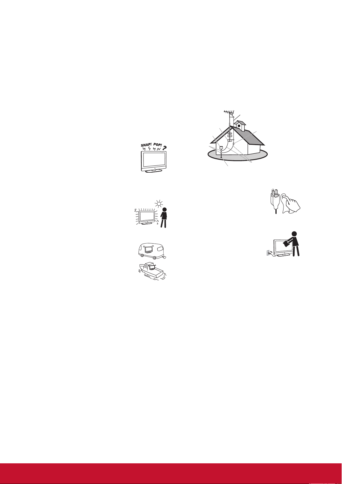
Lightning storms
During a lightning storm, unplug the display from the wall
outlet and disconnect the antenna to prevent damage to
the display.
When not in use
If you will not be using the display set for long periods of
time, the display set should be disconnected from the AC
power outlet to prevent power line surges. The display set
is not disconnected from the AC power source when the
display set is switched off.
To disconnect the display set completel y, unplug from the
AC power outlet.
Overloading
This display set is designed to operate on a
120V AC supply only.
If there are too many appliances connected
to the same AC power outlet, it could result in
a re or an electric shock.
v
Page 9
Optional equipment
If optional equipment is to be installed, leave some space
between optional equipment and the display set. Picture
distortion and/or noisy sound may occur if the display set
is positioned in close proximity to any equipment emitting
electromagnetic radiation.
Small accessories
Keep small accessories in a safe place where children are
unable to reach.
Magnetic inuence
This display contains a strong magnet in the speaker
unit that generates a magnetic eld. Keep any items
susceptible to magnetic elds away from the speaker.
Sound
If you hear snapping or popping sound
comes from the display continuously or
frequently while the display is operating,
unplug the display and consult your dealer
or service technician. It is normal for some
displays to make occasional snapping or
popping sounds, particularly when being
turned on or off.
Use in outdoor
This display is not designed for outdoors
installation. Do not expose the display to
rain, as it may result in a re or an electric
shock. Also, do not expose the display
to direct sunlight, as it may heat up and
become damaged.
Vehicle, ships and other vessels
Do not install this display in a vehicle.
Car accidents may cause the display to fall
down and cause injury.
Do not install this display in a ship or vessel.
If the display is exposed to seawater, it may
cause a re or damage the display.
Medical institutions
Do not place this display in a place where medical
equipment is in use. It may cause the medical equipment
to malfunction.
Volume adjustment
• Adjust the volume to avoid disturbing your neighbors.
Sound carries easily at night. Therefore, we suggest
you close the windows or use headphones.
• When using headphones, adjust the volume to
appropriate levels, or hearing damage may result.
ANTENNAS
Outdoor antenna grounding
If an outdoor antenna is installed, follow the precautions
below. Do not install the outdoor antenna system near
of overhead power lines or other electric light or power
circuits, or where it can come in contact with such power
lines or circuits.
WHEN INSTALLING AN OUTDOOR ANTENNA SYSTEM,
EXTREME CARE SHOULD BE TAKEN TO KEEP FROM
CONTACTING SUCH POWER LINES OR CIRCUITS AS
CONTACT WITH THEM IS ALMOST INVARIABLY FATAL.
Be sure the antenna system is grounded so that it can
provide some protection against voltage surges and builtup static charges.
Section 810 of the National Electrical Code (NEC) in the
U.S.A. and Section 54 of the Canadian Electrical Code
in Canada provides information with in regard to proper
grounding of the mast and supporting structure, grounding
of the lead-in wire to an antenna discharge unit, size of
grounding conductors, location of antenna discharge unit,
connection to grounding electrodes, and requirements for
the grounding electrode.
Antenna grounding according to the National Electrical
Code, ANS/NFPAFPA 70
Antenna
Ground clamp
Electric service
equipment
Ground clamps
Power service grounding
electrode system
Antenna discharge
unit
Grounding conductors
CLEANING
Cleaning the AC power plug
Unplug the AC power plug and clean it
regularly. If the plug is covered with dust
and gathers moisture, its insulation may
deteriorate and result in a re.
Cleaning the screen surface/ cabinet of the display set
When cleaning this display, unplug the AC
power cord. If not, it may result in electric
shock. Use a dry soft cloth to clean the
cabinet of the display. To remove dust
near the screen, wipe it gently with a soft
cloth.
Stubborn stains may be removed with a cloth slightly
dampened with a solution of mild soap and warm water.
Never use strong solvents such as thinner or benzine for
cleaning. If using a chemically pretreated cloth, please
follow the instruction provided on the package. The
ventilation holes can accumulate dust over time.
To ensure proper ventilation, we recommend you to
remove the dust periodically (once a month) using a
vacuum cleaner, while the display is powered off.
Disclaimer
Some chemical cleaners have been reported to damage
the screen and/or case of the display. ViewSonic will not
be liable for damage resulting from use of these cleaners.
CARRYING THE DISPLAY
Carry the display as instructed
To prevent dropping the display and causing serious
injury, you must follow these guidelines:
• Disconnect all cables before carrying the display.
• Carrying the large size display requires at least two or
three people.
• When you carry the display, place your hands as
illustrated and hold it securely. Do not put stress on the
panel and the frame around the screen.
• When carrying the display, do not subject it to shocks,
vibration, or excessive force.
vi
Page 10
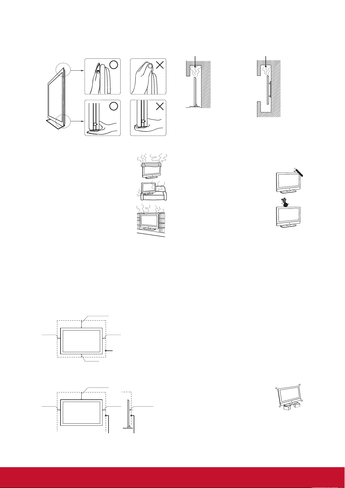
• When lifting or moving the display, hold it securely from
the bottom. Place your palm directly under the panel.
VENTILATION
Slots and openings in display are provided
for ventilation. To ensure reliable operation
of the display and to protect it from
overheating, be sure these openings are
not blocked or covered.
The display may accumulate dust and get
dirty if proper ventilation is not provided.
For proper ventilation, follow the following
guidelines:
• Never install the display face up, down
or sideways.
• Never install the display turned over or
upside down.
• Never cover the slots and openings with
a cloth or other materials.
• Never block the slots and openings by placing the
display on a bed, sofa, rug or other similar surface.
• Never place the display in a conned space, such as a
bookcase or built-in cabinet, unless proper ventilation
is provided.
Leave some space around the display set as shown
below. Otherwise, air-circulation may be inadequate and
cause overheating, which may cause a re or damage to
the display set.
Installed on the wall
11.875 inches
(30.16 cm)
4 inches
(10 cm)
4 inches
(10 cm)
4 inches
(10 cm)
Do not install the display set as follows:
Air circulation is blocked. Air circulation is blocked.
Objects and ventilation holes
Never push any objects into the slots on the display
cabinet as they may touch dangerous voltage points or
short out parts that could result in a re or an electric
shock. Do not place any objects on the display.
MOISTURE
Moisture and ammable objects
• Keep the product away from moisture.
Do not expose this appliance to rain or
moisture. Do not place objects lled with
liquids, such as vases, on the display.
• Do not use power-line operated display
sets near water, such as in places like a
bathtub, washbowl, kitchen sink, laundry
tub, a wet basement, or near a swimming
pool, etc. It may cause re or electric
shock.
• Do not let this display get wet. Never spill liquid of any
kind on the display. If water penetrates into the product,
unplug the power cord and contact ViewSonic.
• Do not operate the display when wet. It may result in
electric shock or damage to the display.
• To prevent re, keep ammable objects or open ame
(e.g. candles) away from the display.
INSTALLATION
Optional wall mount
To do Wall mount installation, you need a Wall-Mount
Bracket. When installing or removing the display using the
Wall-Mount Bracket, be sure to use qualied contractors.
If not properly secured during installation or removal from
the Wall-Mount Bracket, the display may fall and cause
serious injury.
• When installing the display using a Wall-Mount Bracket,
make sure you follow the operating instructions
supplied with the Wall-Mount Bracket.
• Attach the brackets supplied with the Wall-Mount
Bracket.
• The display is not designed for hanging from the
ceiling. It may fall and cause serious injury.
Installed with stand
4 inches
(10 cm)
Leave at least this space around the set.
11.875 inches
(30.16 cm)
4 inches
(10 cm)
2.375 inches
(6.03 cm)
Placement
The display should be installed near an easily accessible
AC power outlet.
Observe the following to prevent the display
from falling from the stand or wall mount.
• Place the display on a stable, level
surface.
• Do not hang anything on the display. Do
not allow children to climb on the display. Do not install
the display in places subject to extreme temperature,
such as in direct sunlight, near a radiator, or heating
vent. If the display is exposed to extreme temperature,
the display may overheat and cause deformation of the
enclosure or cause malfunction.
vii
Page 11

• Do not install the display in a place exposed to direct
air conditioning.
• If the display is installed in such a location, moisture
may condense inside and may cause a malfunction.
• Do not place the display in hot, oily,
humid or excessively dusty places.
• Do not install the display where insects
may enter.
• Do not install the display where it may
be exposed to mechanical vibration.
• Do not install the display in a location where it may
spear up, such as on or behind a pillar, or where you
might bump yourhead on it. It may cause injury.
Preventing the display from toppling over
To prevent the display from toppling over, secure the
display to a wall or stand.
Broken pieces
Do not throw anything at the display. Doing
so may break the screen glass and cause
serious injury.
If the surface of the display cracks, unplug
the AC power cord before touching the
display. Otherwise electric shock may result.
Handling of broken glass and liquid crystal leakage
If the panel gets damaged, crystalline liquid leakage may
occur, or scattered broken glass may result. Do not touch
broken glass or crystalline liquid which is toxic, with bare
hands as cuts, poisoning or skin irritation may occur. Also
do not glass fragments or leaked crystalline liquid get into
your eyes or mouth. Should either contacted your eyes or
mouth, rinse the contacted area thoroughly with water and
consult your doctor.
Placement for watching
We suggest you to watch the display at a distance of
3-7 times that of the screen height, and not in excessive
brightness. It is easy to cause eye fatigue if you watch
display for too long or in a dark room. To obtain clear
picture, do not expose the screen to direct illumination or
sunlight. Use spot lighting directed down from the ceiling
if you can.
SCREEN
• Although the screen is made with high precision
technology and has effective pixels of 99.99% or
more, black dots or bright points or light (red, blue, or
green) may appear constantly on the screen. This is a
structural property of the panel and is not a malfunction.
• The screen is made with high-precision technology. To
achieve a high level of performance and picture quality,
this display’s backlight setting is set to maximize the
brightness of the display. However, uneven brightness
may be observed when the display is viewed in a dark
environment without an input source or a blank screen.
This is a normal condition, not a malfunction of the
display. To improve this condition, change the Picture
mode, Backlight setting, enable the Light Sensor, or
turn on the Power management.
• Avoid exposing the screen surface to direct sunlight. It
is likely to damage the panel.
• Do not push or scratch the screen, or place objects on
top of the display. The image may be uneven or the
panel may be damaged.
• If the display is used in a cold place, a smear may
occur in the picture or the picture may become dark. It
is not caused by a failure. This condition will improve as
the temperature rises.
• When still pictures are displayed continuously, ghosting
may occur. It should disappear after a short period of
time.
• The screen and cabinet get warm when the display is in
use. This is a normal condition.
• Spraying insect repellent with volatile material on the
screen will cause damage.
• Do not make prolonged contact with rubber or plastic
material.
SERVICING
Do not attempt to repair the display
yourself, since opening the cabinet may
expose you to dangerous voltage or other
hazards. Ask qualied service personnel
to do the servicing for your display.
Replacement parts
When replacement parts are required, be sure the
service technician certies in writing that he/she has
used replacement parts specied by the manufacturer
that have the same characteristics as the original parts.
Unauthorized substitutions may cause a re, an electric
shock or other hazards.
Safety check
Upon completion of repairs to the display, ask the service
technician to perform routine safety checks (as specied
by the manufacturer) to determine that the display is safe
for operating, and to so certify.
Ask a qualied service technician to dispose of the
display.
viii
Page 12
Getting Started
This CD is compatible
with Windows
®
and
Mac OS 10.x
Copyright © 2016, ViewSonic Corporation. All rights reserved. All trademarks,
registered or otherwise, are the property of their respective companies. Disclaimer:
ViewSonic Corporation shall not be liable for technical or editorial reeors or omissions
contained herein; nor for i ncidental o r consequential damages r esulting from
furnishing this meterial, or the performance or use of this product. In the interest of
continuing product improvement, ViewSonic Corporation reserves t he right t o
change product specifications without notice. Information in t his CD-ROM m ay
change without notice, No part of this CD-ROM m ay be copied, reproduced, o r
transmitted by any means, for any purpose without prior w ritten permission o f
ViewSonic Corporation.
Made in China
Full HD Professional LED Display
User Guide
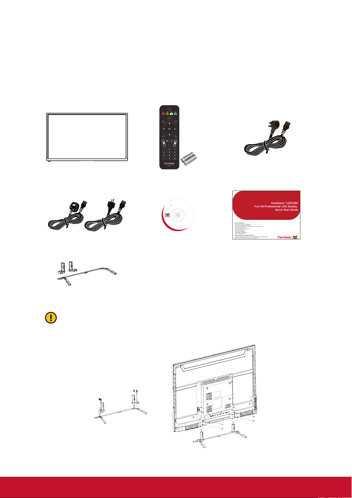
Package Contents
Please make sure the following items are included with your display.
If any items are missing, please contact your dealer.
Display Remote Control with batteries Power Cord
(For US model)
Power Cord
(Only for EU+UK model)
Disc
(User Guide)
Quick Start Guide
Stand STND-043
The photos of the accessories are for reference only. The color of the remote
control, and the type of power cord are variable based on the actual models.
User can use the optional stand assembled into a complete unit as following
detail drawing.
Screw: M4 X L10 x4
Screw: T4 X L12.5 x4
1
Page 13

Installing the Display
Installing the Stand
Screw: T4 x L12.5 x4
Screw: T4 X L12.5 x4
Place the display face down on a protective surface. Then insert the neck onto the
bottom stand and secure the parts by inserting the screws and tightening them with
the screwdriver.
Note: Attaching the stand requires two people.
Disconnecting the Stand
To remove the stand, loosen the screws in the circled area and the neck will come
off.
Screw: T4xL12.5 x4
2
Page 14
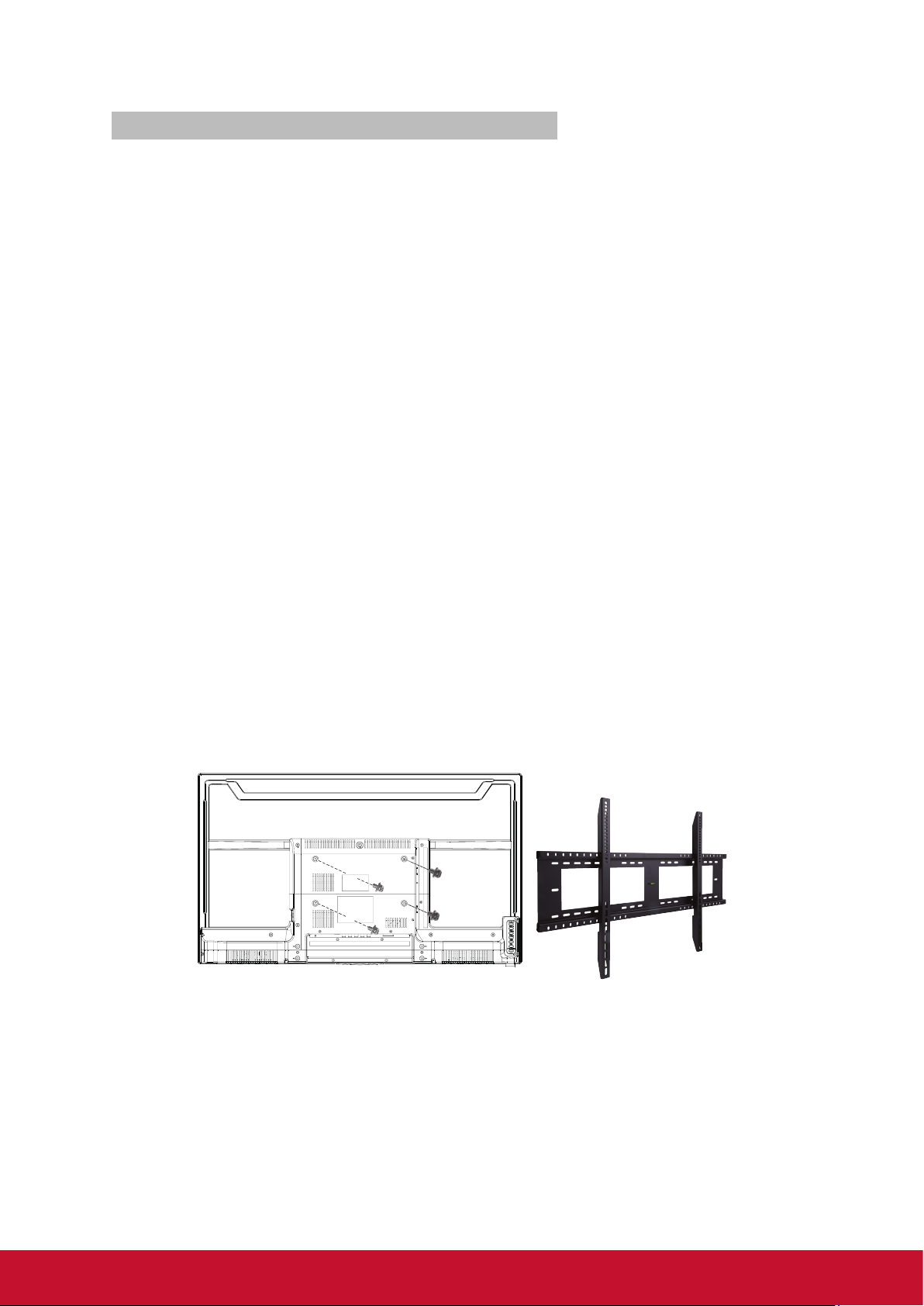
Mounting ViewSonic display to the wall
The display can be used in a free standing position or wall-mounted. Before installing
the product to the wall, please consider the following guidelines:
• Read the Important Safety Instructions, at the start of this manual.
• Do not install in a moist or wet environment. This equipment is intended for
indoor use.
• Do not install near heat source, or strong magnetic fields.
• Use only ViewSonic approved wall-mounting brackets to support the display
weight.
• Before attaching the wall mount plate to the back cover, ensure the product is
working.
• If your display is already set up for free-standing operation, you need to first
remove the stand before mounting the device to the wall.
To attach the wall-mount bracket to display safely, please use the following
guidelines:
• Disconnect the power and any other cables that might hinder moving the
display.
• Set the display on a table or work surface, placing the screen face down on
a towel or woolen blanket to protect the screen surface from damage while
installing plate.
• Before installing the display on the wall, ensure you have recorded the product
serial number on page (i) of the User Guide, as you will need the serial number
to request service where there be a service need.
• Install the wall mount plate to the display using screws NO LONGER than
10mm, as longer screws found in universal (non-ViewSonic) wall mount kits
may damage the power supply causing the unit to fail.
The wall-mount screw type is M4 x L7.
• Mount the wall mount bracket to the wall, ensuring use of proper screws to
support the installation. Ensure there is at least 2.5cm/ 1” of space surrounding
any air-vents of your display to allow adequate cooling during operation.
• Hang the display wall mount plate to the wall mount bracket, completing
installation.
Enjoy your ViewSonic display!
3
Page 15

Wall Mount Kit Specifications (VESA)
C
B
A
When attaching to other building materials, please contact your nearest dealer.
C
D
Product Family inch VESA Spec. (A x B) Standard Screw (C x D) Quantity
CDE 32 200 x 100 mm M4 x L7 4
• ViewSonic provides the standard dimensions for wall mount kits as shown in the
table above.
• To find the perfect mount, please browse www.viewsonic.com or call our service
team: United States 1-800-688-6688, Canada 1-866-463-4775,
Europe +44 (0) 207 382 8250.
• When purchasing our wall mount kit, a detailed install manual and all parts
necessary for assembly are provided.
• The screw length correlative to the thickness of wall mount holder. Do not use the
screws that longer than the standard dimension, as they may cause damage to the
inside of the display set.
4
Page 16
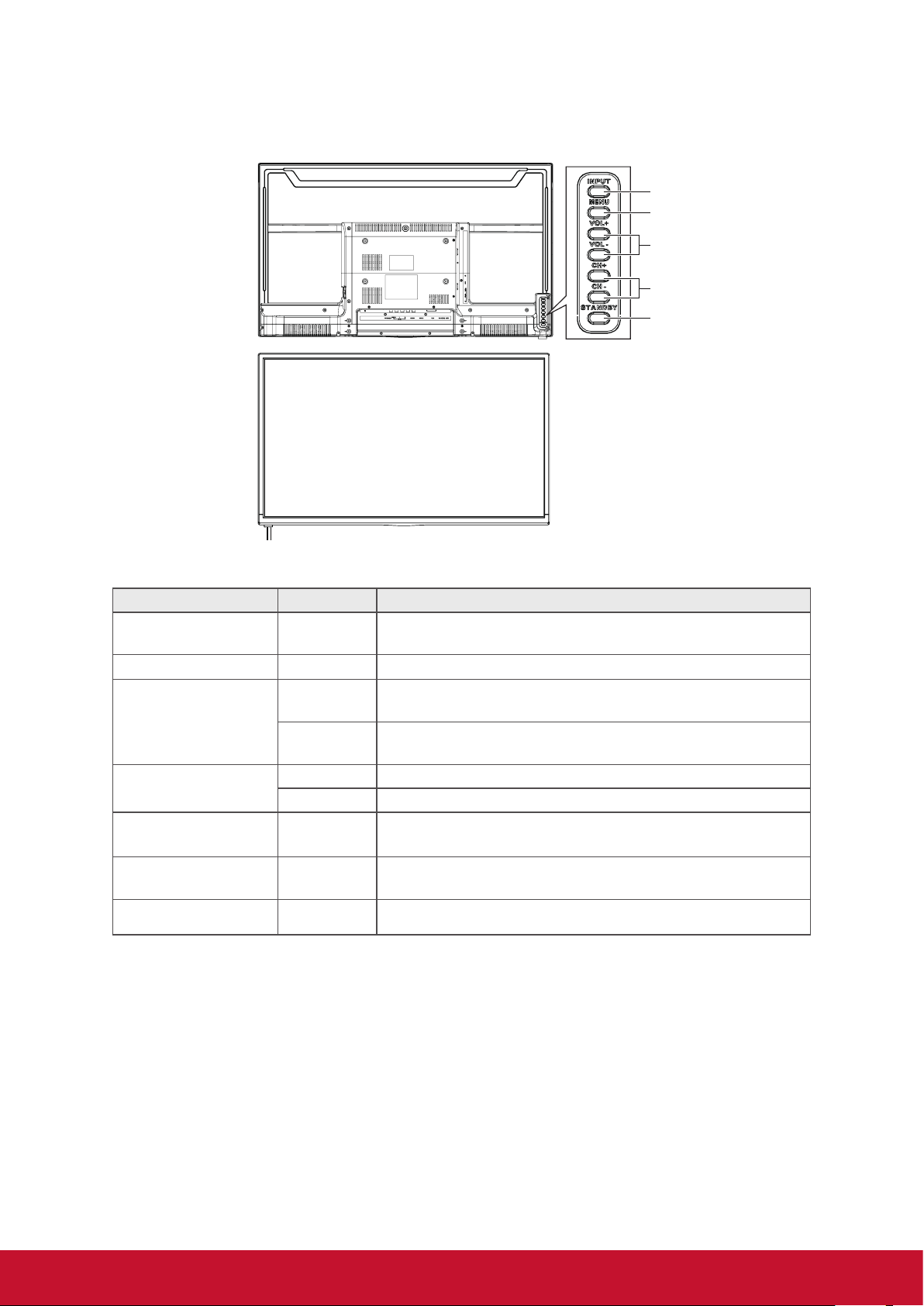
Front View & Key Pad of the Product
1
2
3
4
5
67
Item Icon Description
1 Input INPUT
2 Menu MENU Turn the on-screen display (OSD) menu on / off.
VOL +
3 Volume
VOL -
4 Up & Down
5 Power STANDBY
Remote Control
6
Receiver
7 LED Indicator Green indicates power on. Red indicates standby mode.
CH + Move upward to scroll through menu options.
CH - Move downward to scroll through menu options.
Select the input source.
Enter the submenu.
Increase the volume.
Move to the right or adjust the setting on the OSD menu.
Decrease the volume.
Move to the left or adjust the setting on the OSD menu.
Turn the power on from standby mode. Touch it again to
return to standby mode.
Receive IR signals from the remote control.
5
Page 17

Rear & Side View of the Product
1089 1211
1 2 3 4567
Item Description
Connect to earphones. By connecting the earphones, you can
1 Earphone Jack
2 Audio input (left/ right)
3 CVBS input Connect to the CVBS input of A/V devices.
listen to the sound from the display through the earphones.
If you connect the earphones, the display speakers will be muted.
Connect to the corresponding audio connectors on your A/V
device.
4 YPbPr signal input Connect to the YPbPr output of YPbPr device.
5 SPDIF Optical output Connect to the SPDIF input of Audio amplifier.
6 DVI-D Connect to the DVI-D of PC.
7 HDMI 1 input (with MHL)
8 HDMI 2 input
9 PC/VGA in & PC Audio in Connect to a PC VGA port and a PC line / audio port.
10 USB Connect to USB devices, such as USB flash drive.
11 RS232 signal input
12 IR Out
Connect to the HDMI output of A/V devices. The HDMI 1 has MHL
function to support mobile device.
Reserved for the service technician’s use.
See RS232 protocol section.
Connect to an IR emitter. This will enable the remote control of
external equipment.
6
Page 18

Connecting the Display
HD Cable Box/HD Satellite Box
You can also enjoy high-definition programming by subscribing to a high-definition
cable service or a highdefinition satellite service. For the optimum picture quality, be
sure to connect this device to your display via the HDMI or component video (with
audio) input on the rear side of your display.
HDMI Connection
Rear side of the display
HD cable box /
HD satellite box
HDMI cable
DVI Connection
Rear side of the display
HDMI cable
AUDIO cable
DVI-to-HDMI cable
CATV / Satellite
antenna cable
HD cable box /
HD satellite box
DVI cable
CATV / Satellite
antenna cable
DVI-to-HDMI cableDVI-to-DVI cable
DVI-to-HDMI
adapter
Audio cable
Note:
For alternative DVI connection, connect the HDMI jack (with DVI-to-HDMI cable,
or DVI-to-HDMI adapter), and connect the audio jack to the AUDIO IN jacks of PC
Audio input.
7
Page 19

HDMI Timing Reference Chart
No. Mode HDMI DVI
1 VGA60 (640x480) Yes Yes
2 SVGA60 (800x600) Yes Yes
3 XGA60 (1024x768) Yes Yes
4 SXGA60 (1280x1024) Yes Yes
5 WXGA60 (1360x768) NA NA
6 1280 x 800 NA NA
7 1440 x 900 Yes Yes
8 1680 x 1050 Yes Yes
9 1920 x 1080 Yes Yes
10 480i60 Yes Yes
11 576i50 Yes Yes
12 480P60 Yes Yes
13 576P50 Yes Yes
14 720P50 Yes Yes
15 720P60 Yes Yes
16 1080I50 Yes Yes
17 1080I60 Yes Yes
18 1080P50 Yes Yes
19 1080P60 Yes Yes
20 1080P24 Yes NA
21 1080P30 NA NA
YPbPr or Component Connection
Rear side of the display
Component cable
Component cable
COMPONENT
VIDEO OUT
Pr Y
Pb
Audio cable
AUDIO
LINE OUT
R
L
DVI-HDTV OUT
VIDEO
Audio cable
HD cable box /
HD satellite box
IN
HDMI OUT
OUT
CATV / Satellite
antenna cable
Note:
YPbPr provides better quality than the AV connection.
8
Page 20

AV Connection
Rear side of the display
COMPONENT
VIDEO OUT
Pr Y
Pb
AV cable
AV cable
AUDIO
LINE OUT
R
L
VIDEO
HD cable box /
HD satellite box
DVI-HDTV OUT
HDMI OUT
OUT
CATV / Satellite
antenna cable
IN
Programming your Cable or Satellite Box remote
Refer to the user manual from your service provider to determine the setting.
If it requires:
• 3 digits, please try “566”, “565”, “556”, or “688”. It usually works with DISHNetwork.
• 4 digits, please try “0054”. It usually works with Cox.
• 5 digits, please try “11454”, “11054”, or “10690”. It usually works with DIRECTV.
Personal Computer
Use the display as the monitor of your computer.
Rear side of the display
VGA 15 Pin cable
Audio cable (stereo mini plugs)
Audio cableVGA 15 Pin cable
9
Page 21

PC Timing Reference Chart
No. VGA Timing Panel FullHD (1920 x 1080) Support
Mode Resolution H sync
(kHz)
1 IBM VGA 720 x 400 31.47 70.09 28.32 N/P Yes
2 VESA DMT 640 x 480 31.5 59.94 25.175 N/N Yes
3 VESA DMT 800 x 600 37.88 60.32 40 P/P Yes
4 VESA DMT 1024 x 768 48.36 60 65 N/N Yes
VESA DMT
5
6 VESA DMT 1280 x 800 49.7 59.81 83.5 N/P NA
7 VESA DMT 1280 x 1024 63.98 60.02 108 P/P Yes
8 VESA DMT 1360 x 768 47.71 60.01 85.5 P/P NA
9 VESA DMT 1440 x 900 55.94 59.89 106.5 N/P Yes
10 VESA DMT 1680 x 1050 65.29 59.95 146.25 N/P Yes
11 CEA 1920 x 1080 67.5 60 148.5 P/P Yes
1280 x 768 47.77 59.8 79.5 N/P Yes
V sync
(Hz)
Pixel clock
(MHz)
Polarity Support
Note:
This VGA input does not support interlaced signals.
10
Page 22

Using the Display Features
Remote Control and Display Controls
Inserting Remote Control Batteries
1. Remove the battery cover by pulling then lifting the knob on the cover.
2. Insert the batteries, corresponding to the (+) and (-) markings on the battery
compartment.
3. Reattach the battery cover.
CAUTION
• Only use the specified AAA batteries.
• Do not mix new and old batteries. This may result in creaking or leakage, which
may pose a risk of fire or lead to personal injury.
• Insert batteries according to (+) and (-) markings. Inserting the batteries incorrectly
may result in leakage, which may pose a risk of fire or lead to personal injury.
• Dispose of the battery in accordance with local laws and regulations.
• Keep the batteries away from children or pets.
• When the remote control will not to be used for an extended period, remove the
batteries.
Remote Control and Display Controls
1
2
3
4
5
6
7
8
9
10
11
12
13
14
11
Page 23

Touch keys located at the rear side of the
ENTER
1920 x 1080 @ 60Hz
PC
display operate the same as these buttons
on the remote control.
Button Description
1 POWER
2
3 INPUT
4 P. MODE To set the desired picture mode
/
5
OK buttons
Press this button to turn the power on from standby mode. Press it again to
return to standby mode.
Play or pause the playback in MEDIA mode.
Stop in MEDIA mode.
Jump to previous and next track in MEDIA mode.
Press to display the Source Select list and select the
source with
/ .
To confirm the selection, press OK.
Press these buttons to navigate the OSD menus.
•
/ - move upward/downward to select menu options.
• / - move to the right/left to select the main menu or adjust the set-
tings. You can also use to enter the corresponding submenu.
• OK: Confirm the selection or enter the corresponding submenu.
6 INFO
7 MUTE
Press to display the current state of the display.
Press to turn off the sound. To restore the sound, press this button again, or
press the VOL+/- button.
8 + VOL - Press to adjust the volume.
0~9,
9
- number buttons
Press the respective button to input a character or number.
10 S. MODE To set the desired sound mode
11 EXIT Press to exit OSD setting from menu screen.
12 MENU Press to turn the OSD (On-Screen Display) menu on.
13 + CH - This function is not available for this model. (Only for TV)
14 RECALL To return to previous channel (Only for TV)
12
Page 24

Operation
1920 x 1080 @ 60Hz
PC
Turning the Display On and Off
Press
You can also use the
panel.
* If there is no input signal within 10 minutes, the
display will be turned off automatically.
Adjusting the Volume
Press VOL +/- to adjust volume.
To turn off the volume, press MUTE.
To restore volume, press MUTE again, or press
VOL +/- directly.
on the remote control.
key on the front side of the
Viewing the Displayed Information
To display the current information of the display:
Press INFO, and the current state will be displayed
on the screen. (It shows all or some of the information
about Input, Resolution, etc., depending on the input
source)
* The illustration shows an example of the INFO
screen in an HDMI source.
13
Page 25

Selecting the Input Source
To select the input sources connected to the display:
1. Press INPUT on the remote control.
2. Press
or to select the desired input source.
3. To conrm the selection, press OK.
Enter
Using the Lock Control
With LOCK CONTROL, you can block input source.
Password is required to access the LOCK CONTROL menu. The default is “0000”.
Changing Password
To change a new password:
1. Press MENU to display the OSD main menu.
2. Press
or to select LOCK menu, then press OK
to enter the menu.
3. Enter the password.
4. Press or to select Change Password, then
press to enter its submenu.
5. Enter the old password.
6. Enter your new password.
7. Enter your new password again to Conrm.
The screen will return to the LOCK CONTROL
menu. This indicates the password has been
changed.
8. Press EXIT to exit the menu.
14
Page 26

Picture Menu
Customizing the PICTURE Settings
1. Press MENU to enter the main menu, Press / button to select.
2. Press OK or ▼ button to enter specic submenu.
3. Press MENU again to exit or back to parent menu.
4. Press / button to select among Picture Mode / Contrast / Brightness /
Sharpness /Tint / Color /Blue Light Filter / Color Temperature / Zoom Mode/
DLC.
5. Press OK or button to enter.
6. Press / button to adjust.
7. Press MENU again back to parent menu.
15
Page 27

The PICTURE menu includes the following options:
Picture Mode Cycles among display types: Standard, Dynamic, Theater,
Power Saving, and Personal.
Personal: Allows to store your preferred settings. If you select
the Personal mode, you can individually set the items shown.
Contrast Controls the difference between the brightest and darkest
regions of the picture.
Brightness Controls the overall brightness of the picture.
Sharpness Increase this setting to see crisp edges in the picture; decrease
it for soft edges.
Tint Controls the difference between the blue / red and green
regions of the picture. (Only for NTSC)
Color Controls the color intensity.
Blue Light Filter Reduces the blue ray by lter
Color Temp Adjusts color components independently to achieve a Normal,
Warm, Cool, or Personal effect.
Zoom Mode Adjust how the picture lls the screen.
DLC Set options to set dynamic backlight.
16
Page 28

Audio Menu
Customizing the Audio Settings
1. Press MENU to enter the main menu, Press / button to select.
2. Press OK or ▼ button to enter specic submenu.
3. Press MENU again to exit or back to parent menu.
4. Press / button to select among Sound Mode / Bass / Treble / Digital Output /
Surround Sound / AVC / Balance.
5. Press OK or button to enter.
6. Press / button to adjust.
7. Press MENU again back to parent menu.
The Audio menu includes the following options:
Sound Mode Standard, Music, Movie, Sports, and Personal.
Select a sound mode to achieve ideal sound.
Digital Output Send digital audio to external audio system.
Surround Sound Surround Sound Effect.
AVC Set the auto volume control.
Balance Adjust the left/right audio output effect.
Note: The Bass and Treble are only available in Personal mode, you can adjust as
you like.
17
Page 29

TIME Menu
Customizing the TIME Settings
1. Press MENU to enter the main menu, Press / button to select.
2. Press OK or ▼ button to enter specic submenu.
3. Press MENU again to exit or back to parent menu.
4. Press / button to select Sleep Timer / Time Zone / DST / Time Format / Clock /
TimeManagement.
5. Press OK or button to enter.
6. Press / button to adjust.
7. Press MENU again back to parent menu.
The TIME menu includes the following options:
Sleep Timer Set a timer for the display to turn off automatically.
Time Zone Select your time zone.
DST Set the daylight saving time for your area.
Time Format Select your time format.
Clock Set the date and time.
Time
Management
Set the Wake up/Power off time.
18
Page 30

SETUP Menu
Customizing the SETUP Settings
1. Press MENU to enter the main menu, Press / button to select.
2. Press OK or ▼ button to enter specic submenu.
3. Press MENU again to exit or back to parent menu.
4. Press / button to select Menu Language / Transparent / OSD Time Out /
Restore Default / Software Update / CEC / Blue Screen / Monitor ID / HDMI Mode.
5. Press OK or button to enter.
6. Press / button to adjust.
7. Press MENU again back to parent menu.
The SETUP menu includes the following options:
Menu Language Select an OSD menu language can be displayed. Default
English is selected as menu language.
Transparent Adjust the transparency of the OSD (on screen display) menu.
OSD Time Out Adjust the duration of the OSD (on screen display) menu.
Restore Default Change power on options or reset Monitor to factory default.
Software Update
(USB)
CEC Set to adjust CEC function.
Blue Screen To select the transition type required while changing from one
Set to upgrade the software via the USB.
channel to another.
Monitor ID Adjust Monitor ID for RS232 Setting.
HDMI Mode Select a suitable HDMI mode depending on still or moving con-
tent. Only available in HDMI input.
19
Page 31

Lock Menu
Customizing the Lock Settings
1. Press MENU to enter the main menu, Press
2. Press OK or ▼ button to enter specic submenu.
3. Press MENU again to exit or back to parent menu.
/ button to select.
4. Press / button to select among System Lock / Change Password / Input Block.
5. Press OK or
6. Press / button to adjust.
7. Press MENU again back to parent menu.
The Lock menu includes the following options:
System Lock Enable or disable the lock function
Change
Password
Input Block Block or unblock the input sources.
button to enter.
Enter a new 4-digital password then re-enter it to conrm.
20
Page 32

PC Menu
Customizing the Lock Settings
1. Press INPUT to select PC source.
2. Press MENU to enter the main menu.
3. Press
/ button to select Picture menu.
4. Press OK or button to select Advance.
5. Press OK or button to enter.
6. Press / button to select among H-Pos /
V-Pos / Clock / Phase / Auto.
7. Press / button to adjust.
8. Press MENU again back to parent menu.
The PC menu includes the following options:
H-POS Adjust the horizontal position of the picture.
V-POS Adjust the vertical position of the picture.
Clock Adjust the frequency timing.
Phase Adjust the horizontal interfering lines.
Auto Adjust the screen automatically to the optimal position of the
picture.
21
Page 33

Using the MEDIA OPERATION
1. Plug in USB device, then press INPUT button to set the Input Source to Media.
Press / button to select USB in the source menu, then press OK button to
enter.
AV
USB
2. Press / button to select the option you want to adjust in the main Media menu,
then press OK button to enter.
PHOTO
22
Page 34

3. Enter the storage. Press
4. Press button to start playback. The tool bar will pop up then.
5. For cycling playback, set the Repeat Mode on tool bar to be ALL (R_ALL). Press
EXIT to close the tool bar.
6. Press to pause or to stop the playback. Press button to play the previous
le. Press button to play the next le.
/ / / then OK to pick the les to play.
23
Page 35

Hospitality Menu
Hosptitality Menu
Hosptitality Menu
User can turn on the menu to lock the setting to prevent adjusting. The fixed
setting can also be stored and copied to another same display.
1. Press MENU and 9, 9, 3 button on the remote controller to display the Hospitality
menu.
2. Press or , then to turn On/Off the Hospitality mode. Go next to Hospitality
Function, then press for detail setting. When selecting a menu item with a
submenu ( > > ), press or OK to enter its submenu.
3. Press MENU to return to the previous menu or press EXIT to exit the menu.
EEPROM Init DO
Save Config To USB
Load Config From USB
Hospitality
Hospitality Function
Power On Mode
Remote Control Code
Menu Key Enable
Remote Control
Power On Volume
Max Volume
AV
VOL Max
Compoent
AV
HDMI1
YPbPr
HDMI2
HDMI1
DVI
HDMI2
PC
HDMI3
USB
PC
Power Input
USB
Power Input
>>
>>
On
>>
Off
Enable
100
Enable
Enable
Enable
Enable
Enable
Enable
Enable
Enable
Enable
Enable
Enable
Enable
Enable
Enable
30
100
AV
0
EEPROM Init Clean up the setting to its initial value.
Save Config To
USB
Load Config From
USB
Save the hospitality configuration into USB
drive.
Load the hospitality configuration from USB
drive.
Hospitality Turn on or off the Hospitality function.
Menu item Description
Hospitality
Function
Enter the hospitality sub-menu.
Power ON Mode Decide how to turn on the display from AC
power outage.
Menu item Description
0
Remote Customer
Code
Select the specific remote ID (0, 1, or 2). (For
specific model only)
Menu Key Enable or disable the MENU key.
Remote Control Enable, disable remote or set as IR pass
through
Power On Volume Set the default volume for each power-on
Max Volume Set the limitation of maximum volume
AV
AV
Compoent
HDMI1/2
DVI
Enable or disable the input source.
PC
USB
Power Input Default input source for each power on.
24
Page 36

Other Information
Troubleshooting
Please contact ViewSonic service team directly if you have questions, service needs,
or require technical assistance related on the use of your display.
Contact ViewSonic Service Team at:
http://www.ViewSonic.com
Or call our service team:
United States 1-800-688-6688
Canada 1-866-463-4775
Europe +44 (0) 207 382 8250
Problem Possible Solution
• Make sure the AC power cord is properly connected to the wall
No power
No picture
Strange color, light color, or
color misalignment
No sound
Remote control unit does not
operate
outlet.
• Plug another electrical device (like a radio) to the power outlet
to verify that the outlet is supplying the proper voltage.
• Make sure that the cable connection to other components are
properly installed.
• Make sure that setup has been done correctly after
connections.
• Make sure the correct input is selected and the input signal is
compatible.
• Ensure that the video cable is securely connected.
• The picture may appear dim in a brightly lit room.
• Adjust the display settings.
• Check the input signal setting.
• Check your audio connections to other components are
properly installed.
• The MUTE button may have been pressed, try pressing this
button again.
• Check your audio settings, your display audio may be set to
minimum.
• Press VOL + on the remote control.
• Make sure the batteries are inserted correctly.
• Batteries could be weak or dead. Replace with new batteries.
• Check if there is a fluorescent light illuminated near the remote
control sensor.
• The path of the remote control beam may be blocked. Make
sure the path is clear and that the remote control is aimed at
the remote control sensor on the display.
• Press
display.
• Press MENU on the remote control to see if there is an OSD
menu shown on the screen.
• Press only one button at a time and it is the correct one for the
operation you want to perform.
on the remote control to see if you can turn on the
25
Page 37

Problem Possible Solution
• External influences such as lightning or static electricity may
Unit cannot be operated
Power is cut off suddenly
Picture is cut off/with sidebar
screen
cause improper operation. In this case, operate the unit after
first turning on the power of the display and the AV System, or
unplug the AC cord for 1 to 2 minutes, then replug again.
• Make sure the sleep timer is turned off.
• Make sure the PC or video signal cable is connected properly.
• The internal temperature of the unit has increased. Remove
any objects blocking the vent or clean as necessary.
• Make sure the video signal cable is connected properly.
• Adjust the Screen Size setting on the Picture menu.
• Press ASPECT repeatedly on the remote control to switch to
the display mode you prefer.
26
Page 38

Specifications
Model CDE3202
(LED Backlight)
Input signal
Compatibility PC Up to 1920 x 1080 (CEA mode)
Speaker Output 10W x 2 @ THD=10% (max)
Audio Output 1 Earphone jack, 1 SPDIF (optical)
RS232 Output RS232 communication
Remote Control Out Remote control out (RC5 38KHz)
Power Voltage AC 100~240V (50/60Hz)
Screen Size 31.5” (80.01 cm) FHD 60Hz
Aspect Ratio 16:9
RGB
DVI-D 1 DVI-D 30PIN terminal white color
Video
Audio
USB
1 RGB analog (0.7/1.0 Vp-p, 75 ohms) Separate Sync,
fh: 31.47-63.98 kHz, fv:59.8-70.09 Hz
1 composite RCA (shared with Y), 1 YPbPr component, 2
HDMI (one has MHL function)
1 mini-stereo (for PC/VGA audio in),
1 pair of RCA (L/R) stereo
JPG / BMP / PNG / MPG / MPEG / MP4 / MKV / TS / TP /
TRP / VOB/ AVI / RM / RMVB / MOV / DAT / FLV / WMA /
WMV / MP3 / WAV / M4A Format
Operating
conditions
Storage condition
Dimensions
Weight(Net)
Regulations
Power
consumption
Warning: Do not set the graphics card in your computer to exceed these refresh rates; doing so
may result in permanent damage to the display.
Temperature 0°C to + 40°C
Humidity 20% to 90% (no condensation)
Temperature -20°C to + 60°C
Humidity 20% to 90% (no condensation)
With stand 729.2 x 465.7 x 164.3 mm (28.71 x 18.33 x 6.47
Physical
(L) x (W) x (H)
With stand 5.4Kg (11.88 lb)
Without stand 5.3Kg (11.66 lb)
On 41 W (typ) / 68W (max)
Stand by < 0.5W
inches )
Without stand 729.2 x 429.7 x 48.5 mm (28.71 x 16.92 x
1.91 inches )
cTUVus, FCC-B w/ ICES003, DOE Energy Star, NOM or
cTUVus-MX-CoC, Mexico Energy, CB of TUV
Note:
Product Specifications are subject to change without notice.
27
Page 39

RS232 Protocol
1. Introduction
This document describes the hardware interface spec and software protocols
of RS232 interface communication between ViewSonic Commercial TV / Digital
Signage and PC or other control unit with RS232 protocol.
The protocol contains three sections command:
• Set-Function
• Get-Function
• Remote control pass-through mode
※ In the document below, “PC” represents all the control units that can sent or
receive the RS232 protocol command.
2. Description
2.1 Hardware specification
Viewsonic TV communication port on the rear side
(1) Connector type: DSUB 9-Pin Male
(2) Pin Assignment
Male DSUB 9-Pin
(outside view)
Pin # Signal Remark
1 NC
2 RXD Input to Commercial TV or DS
3 TXD Output from Commercial TV or DS
4 NC
5 GND
6 NC
7 NC
8 NC
9 NC
frame GND
* Use of crossover (null modem) cable required for
use with PC.
2.2 Communication Setting
• Baud Rate Select: 9600bps (fixed)
• Data bits: 8bits (fixed)
• Parity: None (fixed)
• Stop Bits: 1 (fixed)
2.3 Command Message Reference
PC sends to Monitor command packet followed by “CR”. Every time PC sends
control command to the Monitor, the Monitor shall respond as follows:
1. If the message is received correctly it will send “+” (02Bh) followed by “CR” (00Dh)
2. If the message is received incorrectly it will send “-” (02Dh) followed by “CR”
(00Dh)
28
Page 40

3. Protocol
3.1 Set-Function Listing
The PC can control the TV/DS for specific actions. The Set-Function command
allows you to control the TV/DS behavior in a remote site through the RS232 port.
The Set-Function packet format consists of 9 bytes.
Set-Function description:
Length: Total Byte of Message excluding “CR”
TV/DS ID: Identification for each of TV/DS (01~98; default is 01)
ID “99” means to apply the set command for all connected displays.
Under such circumstances, only ID#1 display has to reply.
The TV/DS ID can be set via the OSD menu for each TV/DS set.
Command Type: Identify command type,
“s” (0x73h) : Set Command
“+” (0x2Bh) : Valid command Reply
“-” (0x2Dh) : Invalid command Reply
Command: Function command code: One byte ASCII code
Value[1~3]: Three bytes ASCII that defines the value
CR: 0x0D
Set-Function format:
Send: (Command Type= “s”)
Name Length ID Command Type Command Value1 Value2 Value3 CR
Byte Count 1 Byte 2 Byte 1 Byte 1 Byte 1 Byte 1 Byte 1 Byte 1 Byte
Bytes order 1 2~3 4 5 6 7 8 9
Reply: (Command Type= “+” or “-”)
Name Length ID Command Type CR
Byte Count 1 Byte 2 Byte 1 Byte 1 Byte
Bytes order 1 2~3 4 5
[NOTE]
1. The reply for “Power on” command is the exception for VT2405LED-1 and
VT3205LED. It’s 0x322B0D ( 2+<CR>).
2. When PC applies command to all displays (ID=99), only the #1 set needs to reply
by the name of ID=1.
Example1: Set Brightness as 76 for TV-02 and this command is valid
Send (Hex Format)
Name Length ID Command Type Command Value1 Value2 Value3 CR
Hex
0x38
0x30
0x32
0x73 0x24 0x30 0x37 0x36 0x0D
Reply (Hex Format)
Name Length ID Command Type CR
Hex
0x34
0x30
0x32
0x2B 0x0D
29
Page 41

Example2: Set Brightness as 176 for TV-02 and this command is NOT valid.
Send (Hex Format)
Name Length ID Command Type Command Value1 Value2 Value3 CR
Hex
0x38
0x30
0x32
0x73 0x24 0x31 0x37 0x36 0x0D
Reply (Hex Format)
Name Length ID Command Type CR
Hex
0x34
0x30
0x32
0x2D 0x0D
Set-function table
Command
Set Function Length ID
Power on/off
(standby)
Input Select 8 s “ 22 000 : TV
Contrast 8 s # 23 000 ~ 100
Brightness 8 s $ 24 000 ~ 100
Sharpness 8 s % 25 000 ~ 100
Color 8 s & 26 000 ~ 100
Tint 8 s ‘ 27 000 ~ 100
Color mode 8 s ) 29 000: Normal
Sound 8 s - 2D 000: SRS Off
Bass 8 s . 2E 000 ~ 100 (for TV)
Treble 8 s / 2F 000 ~ 100 (for TV)
Balance 8 s 0 30 000 ~ 100 (for TV)
Picture Size 8 s 1 31 000 : FULL
8 s ! 21 000: STBY
Type
(ASCII)
Code
(ASCII)
Code
(Hex)
Value Range
(Three ASCII bytes)
001: ON
001 : AV
002 : S-Video
003 : YPbPr
004 : HDMI
014: HDMI2
024: HDMI3
034: HDMI4
005 : DVI
006 : VGA1
016: VGA2
026: VGA3
007: OPS/PC
017: Android
008: Internal memory
009: DP
001: Warm
002: Cold
003: Personal
001: SRS On
001 : NORMAL
002 : CUSTOM
003 : DYNAMIC
004 : REAL
Comments
Exclude VT2405-1, and
VT3205
1. No need for USB
2. For the case of two
more same sources,
the 2nd digital is
used to indicate the
extension.
3. Exclude VT2405-1, and
VT3205.
(for TV)
Sets Balance position
(for DS)
30
Page 42

OSD language 8 s 2 32 000: English
001: French
002: Spanish
Power lock 8 s 4 34 000 : Unlock
001 : Lock
Volume 8 s 5 35 000 ~ 100
900:Volume
down (-1)
901:Volume
up (+1)
Mute 8 s 6 36 000: OFF
001: ON (mute)
Button lock 8 s 8 38 000: Unlock
001: Lock
PIP-Mode 8 s 9 39 000 : OFF
001: PIP
002: PBP
PIP-Sound
select
PIP-Position 8 s ; 3B 000: Up
PIP-Input 8 s 7 37 000 : TV
TV channel
(DTV)
TV channel
(ATV)
Menu lock 8 s > 3E 000: Unlock
Number 8 s @ 40 000~009 (for TV)
Key Pad 8 s A 41 000: UP
8 s : 3A 000: Main
001: PIP
001: Down
002: Left
003: Right
001 : AV
002 : S-Video
003 : YPbPr
004 : HDMI
014: HDMI2
024: HDMI3
005 : DVI
006 : VGA
007: OPS/ PC
8 s < 3C
8 s = 3D 001~999 (for TV)
For -0:
001~999
A00~F99
(1000~1599)
For -k:
1st and 2nd char are
same as -0
3th char is CHAR
[ASC (3th digi) +
k x 10 ]
001: Lock
001: DOWN
002: LEFT
003: RIGHT
004: ENTER
005: INPUT
006: MENU/EXIT
Extend the value for more
supported languages
(for DS)
(for DS)
(for DS)
(for DS)
For the case of two more
same sources, the 2nd
digital is used to indicate
the extension.
(for TV)
1. Channel OSD number
but not frequency
number
2. For VT3255, and
VT4236 only
31
Page 43

Remote
Control
Setup wizard 8 s C 43 000: Disable
Tiling-Mode 8 s P 50 000: OFF
TilingCompensation
Tiling-H by V
Monitors
Tiling-Position 8 s S 53 001~025 (for DS)
Date 8 s V 56 0xx: Year
Time 8 s W 57 0xx: Hour+Min
Restore default 8 s ~ 7E 000 Resets HDTV to factory
8 s B 42 000: Disable
001: Enable
002: Pass through
001: Enable
001: ON
8 s Q 51 000: OFF
001: ON
8 s R 52 01x~09x: H
0x1~0x9: V
1xx: Month+Day
(See example in
Note)
10x: Sec
(See example in
Note)
Disable: RCU has no
effect on HDTV.
Enabled: RCU controls
the HDTV.
This is the power up
default on the HDTV.
Pass through: RCU has
no effect on HDTV and all
RCU command codes are
transmitted to FC via the
RS232 port.
(for TV)
Disable: to skip the initial
setup wizard
(for DS)
(for DS)
Bezel width
compensation
(for DS)
nd
1. 2
digital for H
monitors
2. 3rd digital for V monitors
Copy the screen of
Position# to identified
display
For specific models only
For specific models only
setting
Note:
1. Behavior at lock modes
Lock Mode Behavior
1. Lock all buttons of front panel and RCU, except for “Power”
Button Lock
MENU Lock
POWER Lock
Remote control disable Lock the keys on RCU, but keep the buttons of front panel workable.
2. All the SET functions should be workable via RS32, even the ones with
according hot key in RCU like Mute,…etc.
1. Lock “MENU’ key of front panel and RCU
2. The Factory and Hospitality modes should not be blocked for the model
using MENU-combined key to enter these two modes. Alternative
approach will be indicated separately if any limitation by model.
1. Lock “POWER” key of front and RCU.
2. The SET_POWER on/off should be workable via RS232, but does not
mean the POWER lock will be released under this case.
3. Can not be un-locked by reset in OSD setting
4. Will auto AC power-on in power-lock
5. Under power-lock, the set will not enter power saving when no PC
signal and neither not turn off when no other video signals after 15min.
32
Page 44

2. Example for value setting of SET_TV channel DTV
012-0: 0x 30 31 32
012-1: 0x 30 31 42
1012-2: 0x 41 31 52
1512-3: 0x 46 31 62
3. Tiling definition of H Monitors/ V Monitors/ and Position
4. Date & Time format definition
Value 1 Value 2 Value 3
Date
Time
0: Year Year code of the rst 2 digis Year code of the last 2 digis
1: Month+Day Month code Day code
0:Hour(24-hr format)+Min Hour code Minute code
1: Sec 0 Second code
33
Page 45

Hex code (in hex) = Original data (in dec) + 20
Date &
Time
0 space 20 16 6 36 32 R 52 48 h 68
1 ! 21 17 7 37 33 S 53 49 i 69
2 “ 22 18 8 38 34 T 54 50 p 70
3 # 23 19 9 39 35 U 55 51 q 71
4 $ 24 20 @ 40 36 V 56 52 r 72
5 % 25 21 A 41 37 W 57 53 s 73
6 & 26 22 B 42 38 X 58 54 t 74
7 ’ 27 23 C 43 39 Y 59 55 u 75
8 ( 28 24 D 44 40 ` 60 56 v 76
9 ) 29 25 E 45 41 a 61 57 w 77
10 0 30 26 F 46 42 b 62 58 x 78
11 1 31 27 G 47 43 c 63 59 y 79
12 2 32 28 H 48 44 d 64
13 3 33 29 I 49 45 e 65
14 4 34 30 P 50 46 f 66
15 5 35 31 Q 51 47 g 67
Code
(ASCII)
Code
(Hex)
Date &
Time
Code
(ASCII)
Code
(Hex)
Date &
Time
Code
(ASCII)
Code
(Hex)
Date &
Time
Code
(ASCII)
Month: 1~12
Day: 1~31
Hour: 00~23
Min: 00~59
Sec: 00~59
Code
(Hex)
5. Set Date & Time example
Date: 2015-1/31
Time: 16:27:59
Send: 0x 38 30 31 73 56 30 40 35 0D (Year “20” “15”)
Send: 0x 38 30 31 73 56 31 21 51 0D (Month “1”, Day ”31”)
Send: 0x 38 30 31 73 57 30 36 47 0D (Hour “16”, Min “27”)
Send: 0x 38 30 31 73 57 31 30 79 0D (“0”, Sec “59”)
34
Page 46

3.2 Get-Function Listing
The PC can interrogate the TV/DS for specific information. The Get-Function packet
format consists of 9 bytes which is similar to the Set-Function packet structure. Note
that the “Value” byte is always = 000.
Get-Function description:
Length: Total Byte of Message excluding “CR”
TV/DS ID: Identification for each of TV/DS (01~98; default is 01)
Command Type: Identify command type,
“g” (0x67h) : Get Command
“r” (0x72h) : Valid command Reply
“-“ (0x2Dh) : Invalid command Reply
Command: Function command code: One byte ASCII code
Value[1~3]: Three bytes ASCII that defines the value
CR: 0x0D
Get-Function format:
Send: (Command Type= “g”)
Name Length ID Command Type Command Value1 Value2 Value3 CR
Byte Count 1 Byte 2 Byte 1 Byte 1 Byte 1 Byte 1 Byte 1 Byte 1 Byte
Bytes order 1 2~3 4 5 6 7 8 9
[NOTE] Get “Power STBY status” is the exception for VT2405LED-1 and
VT3205LED.
Reply: (Command Type= “r” or “-”)
If the Command is valid, Command Type = “r”
Name Length ID Command Type Command Value1 Value2 Value3 CR
Byte Count 1 Byte 2 Byte 1 Byte 1 Byte 1 Byte 1 Byte 1 Byte 1 Byte
Bytes order 1 2~3 4 5 6 7 8 9
[NOTE] The reply for “Power STBY status” command is the exception for
VT2405LED-1 and V3205LED. It’s 0x36 72 6C 30 30 30 0D ( 6rl000<CR>).
If the Command is Not valid, Command Type= “-”
Name Length ID Command Type CR
Byte Count 1 Byte 2 Byte 1 Byte 1 Byte
Bytes order 1 2~3 4 5
Example1: Get Brightness from TV-05 and this command is valid.
The Brightness value is 67.
Send (Hex Format)
Name Length ID Command Type Command Value1 Value2 Value3 CR
Hex
0x38
0x30
0x35
0x67 0x62 0x30 0x30 0x30 0x0D
35
Page 47

Reply (Hex Format)
Name Length ID Command Type Command Value1 Value2 Value3 CR
Hex
0x38
0x30
0x35
0x72 0x62 0x30 0x36 0x37 0x0D
Example2: Get Brightness from TV-05 , but the Brightness command ID is error
and it is NOT in the command table.
Send (Hex Format)
Name Length ID Command Type Command Value1 Value2 Value3 CR
Hex
0x38
0x30
0x35
0x67 0XD3 0x30 0x30 0x30 0x0D
Reply (Hex Format)
Name Length ID Command Type CR
Hex
0x34
0x30
0x35
0x2D 0x0D
Get-function table
Set Function Length ID
Get-Contrast 8 g a 61 000 ~ 100
Get-Brightness 8 g b 62 000 ~ 100
Command
Type
Command
Code
(ASCII)
Code
(Hex)
Value Range
(Three ASCII bytes)
Comments
Get-Sharpness 8 g c 63 000 ~ 100
Get-Color 8 g d 64 000 ~ 100
Get-Tint 8 g e 65 000 ~ 100
Get-Volume 8 g f 66 000 ~ 100
Get-Mute 8 g g 67 000: Off
001: On (muted)
Get-Input select 8 g j 6A 000~ See Set-function
table
Get-Power
status: ON/STBY
Get-Remote
control
Get-Power lock 8 g o 6F 000: Unlock
Get-Button lock 8 g p 70 000: Unlock
Get-Menu lock 8 g q 71 000: Unlock
Get-Setup wizard 8 g s 73 000: Disable
Get-PIP mode 8 g t 74 000 : OFF
8 g l 6C 001: ON
000: STBY
8 g n 6E 000: Disable
001: Enable
002: Pass through
001: Lock
001: Lock
001: Lock
001: Enable
001: PIP
002: PBP
Exclude VT2405-1,
and VT3205
Gets RCU mode
status
(for TV)
(for DS)
36
Page 48

Get-PIP input 8 g u 75 000 ~ (for DS)
See Set-function
table
Get-Tiling Mode 8 g v 76 000: OFF
001: ON
Get-Tiling
Compensation
Get-Tiling H by V
monitors
Get-Tiling
position
Get-ACK 8 g z 7A 000 This command is
Get-Thermal 8 g 0 30 000~100:
Get-Power on/
off log
Get-Date 8 g 2 32 000
Get- Time 8 g 3 33 000
8 g w 77 000: OFF
001: ON
8 g x 78 01x~09x: H monitors
0x1~0x9: V monitors
8 g y 79 000: OFF
001~025
0~+100 deg C
-01~-99:
-1~-99 deg C
8 g 1 31 000
(See below note)
(See the Set-Date
command)
(See the Set-Time
command)
(for DS)
(for DS)
Bezel width
compensation
(for DS)
nd
1. 2
digital for H
monitors
rd
2. 3
digital for V
monitors
(for DS)
Copy the screen
of Position# to
identified display
used to test the
communication link.
For specific models
only
For specific models
only
For specific models
only
For specific models
only
[NOTE]
1. Power on/off log data is replied as 6 sequential strings in following order.
2. Time log data definition
Value 1 Value 2 Value 3
On/ Off indicator
0: Off
1: On
Month code Day code
Hour code Minute code
37
Page 49

Hex code (in hex) = Original data (in dec) + 20
Date &
Time
0 space 20 16 6 36 32 R 52 48 h 68
1 ! 21 17 7 37 33 S 53 49 i 69
2 “ 22 18 8 38 34 T 54 50 p 70
3 # 23 19 9 39 35 U 55 51 q 71
4 $ 24 20 @ 40 36 V 56 52 r 72
5 % 25 21 A 41 37 W 57 53 s 73
6 & 26 22 B 42 38 X 58 54 t 74
7 ’ 27 23 C 43 39 Y 59 55 u 75
8 ( 28 24 D 44 40 ` 60 56 v 76
9 ) 29 25 E 45 41 a 61 57 w 77
10 0 30 26 F 46 42 b 62 58 x 78
11 1 31 27 G 47 43 c 63 59 y 79
12 2 32 28 H 48 44 d 64
13 3 33 29 I 49 45 e 65
14 4 34 30 P 50 46 f 66
15 5 35 31 Q 51 47 g 67
Code
(ASCII)
Code
(Hex)
Date &
Time
Code
(ASCII)
Code
(Hex)
Date &
Time
Code
(ASCII)
Code
(Hex)
Date &
Time
Code
(ASCII)
Month: 1~12
Day: 1~31
Hour: 00~23
Min: 00~59
Code
(Hex)
3. Get Time log data example
Assumed the power-on/off record of display#01 as below
2014-8/31 08:00 On
2014-8/31 22:00 Off
2014-9/1 10:30 On
2014-9/1 11:00 To send “GET-Time log” command
Send: 0x 38 30 31 67 31 30 30 30 0D
Reply:
#1 0x 38 30 31 72 31 31 28 51 0D (On 8/31)
#2 0x 38 30 31 72 31 31 28 20 0D (On 08:00)
#3 0x 38 30 31 72 31 30 28 51 0D (Off 8/31)
#4 0x 38 30 31 72 31 30 42 20 0D (Off 22:00)
#5 0x 38 30 31 72 31 31 29 21 0D (On 9/1)
#6 0x 38 30 31 72 31 31 30 50 0D (On 10:30)
4. Get Date & Time example
Assumed the current date/time of display#01 as below
Date: 2015-1/31
Time: 16:27:59
38
Page 50

Send: 0x 38 30 31 67 32 30 30 30 0D (Get Date)
Reply:
#1 0x 38 30 31 72 32 30 40 35 0D (Year “20” “15”)
#2 0x 38 30 31 72 32 31 21 51 0D (Month “1”, Day ”31”)
Send: 0x 38 30 31 67 33 30 30 30 0D (Get Time)
Reply:
#1 0x 38 30 31 72 33 30 36 47 0D (Hour “16”, Min “27”)
#2 0x 38 30 31 72 33 31 30 79 0D (“0”, Sec “59”)
3.3 Remote Control Pass-through mode
When PC sets the TV/DS to Remote Control Pass through mode, the TV/DS shall
send a 7-byte packet (followed by “CR”) in response to RCU button activation. Note,
that in this mode the RCU shall have no effect on the TV/DS function. For example:
“Volume+” will not change the volume in the LCD but only sends “Volume+” code to
PC over the RS232 port.
IR Pass Through-Function format
Reply: (Command Type= “p”)
Name Length ID Command Type
Byte Count 1 Byte 2 Byte 1 Byte 1 Byte 1 Byte 1 Byte
Bytes order 1 2~3 4 5 6 7
RCU Code1
(MSB)
RCU Code2
(LSB)
CR
Example1: Remote Control pass-through when “VOL+” key is pressed for
TV-05 Send (Hex Format)
Name Length ID Command Type
Hex
1 01
2 02
3 03
4 04
5 05
6 06
7 07
8 08
9 09
0 0A
- 0B
RECALL (LAST) 0C
INFO (DISPLAY) 0D
0x36
Key Code (HEX)
0x30
0x35
0x70 0x31 0x30 0x0D
0E
RCU Code1
(MSB)
RCU Code2
(LSB)
CR
39
Page 51

ASPECT (ZOOM, SIZE) 0F
VOLUME UP (+) 10
VOLUME DOWN (-) 11
MUTE 12
CHANNEL/PAGE UP (+)/
BRIGHTNESS+
CHANNEL/PAGE DOWN (-)/
BRIGHTNESSPOWER 15
SOURCES (INPUTS) 16
SLEEP 19
MENU 1A
UP 1B
DOWN 1C
LEFT (-) 1D
RIGHT (+) 1E
OK (ENTER, SET) 1F
EXIT 20
■
RED
GREEN
YELLOW
BLUE
(F1)
■
■
(F4)
(F2)
■
(F3)
13
14
17
18
21
22
23
24
25
26
27
28
29
2A
2B
2C
2D
2E
2F
Note:
1. This IR-pass-through code is different with RCU key code.
2. Special control sequence for POWER key under IR-pass through mode.
2-1. When display is OFF and receives the POWER code: The display will turn on
itself, then forward the POWER code to the host via RS232.
2-2. When display is ON and receives the POWER code: The display will forward
the POWER code to the host via RS232, then turns off itself.
3. The code of VOLUME UP and VOLUME DOWN will repeatedly output when
press and hold the keys.
40
Page 52

Customer Support
For technical support or product service, see the table below or contact your reseller.
NOTE: You will need the product serial number.
Use with other Wall-Mount kit may cause instability and possibly result in injury.
To find the perfect mount for CDE3202, please browse
www.viewsonic.com or call our service team: United States 1-800-688-6688,
Canada 1-866-463-4775, Europe +44 (0) 207 382 8250.
Country/Region Website
United States www.viewsonic.com T= 1-800-688-6688 service.us@viewsonic.com
Canada www.viewsonic.com T= 1-866-463-4775 service.ca@viewsonic.com
Europe www.viewsoniceurope.com www.viewsoniceurope.com/uk/support/call-desk/
Latin America
(Argentina)
Latin America
(Chile)
Latin America
(Columbia)
Latin America
(Mexico)
Nexus Hightech Solutions, Cincinnati #40 Desp. 1 Col. De los Deportes Mexico D.F.
Tel: 55) 6547-6454 55)6547-6484
Other places please refer to http://www.viewsonic.com/la/soporte/servicio-tecnico#mexico
Latin America
(Peru)
www.viewsonic.com/la/
www.viewsonic.com/la/
www.viewsonic.com/la/
www.viewsonic.com/la/
www.viewsonic.com/la/
T= Telephone
C = CHAT ONLINE
C= http://www.viewsonic.com/la/
soporte/servicio-tecnico
C= http://www.viewsonic.com/la/
soporte/servicio-tecnico
C= http://www.viewsonic.com/la/
soporte/servicio-tecnico
C= http://www.viewsonic.com/la/
soporte/servicio-tecnico
C= http://www.viewsonic.com/la/
soporte/servicio-tecnico
Email
soporte@viewsonic.com
soporte@viewsonic.com
soporte@viewsonic.com
soporte@viewsonic.com
soporte@viewsonic.com
41
Page 53

 Loading...