

Page 1

Model No. VCDTS23283
19” Digital Controlled Color Monitor
Service Manual
ViewSonic A91f+-1
ViewSonic
381 Brea Canyon Road, Walnut, California 91789 USA - (800) 888-8583
(A91f+-1_SM_830 Rev. 1a – Apr. 2004)
Page 2

Copyright
Copyright
¤
2004 by ViewSonic Corporation. All rights reserved. No part of this publication may be
reproduced, transmitted, transcribed, stored in a retrieval system, or translated into any language or
computer language, in any form or by any means, electronic, mechanical, magnetic, optical, chemical,
manual or otherwise, without the prior written permission of ViewSonic Corporation.
Disclaimer
ViewSonic makes no representations or warranties, either expressed or implied, with respect to the
contents hereof and specifically disclaims any warranty of merchantability or fitness for any particular
purpose. Further, ViewSonic reserves the right to revise this publication and to make changes from time
to time in the contents hereof without obligation of ViewSonic to notify any person of such revision or
changes.
Revision History
Revision Date Description Of Changes Approval
1a 06/15/04 Initial Release DCN- 4408 Angela Lu
Trademarks
ViewSonic is a registered trademark of ViewSonic Corporation.
All other trademarks used within this document are the property of their respective owners.
Optiquest is a registered trademark of ViewSonic Corporation.
i
ViewSonic Corporation Confidential
-
Do Not Copy A91f+-1
Page 3

TABLE OF CONTENTS
2. Specification
3. Front Panel Function Control Description
4. Circuit Description
6. Trouble Shooting Flow Chart
9. Block Diagram,
Schematic Diagrams
7. Recommended Spare Parts List
1. Precautions and Safety Notices
5. Adjusting Procedure
8. Exploded Diagram And Spare Parts List
10
. PCB Layout Diagrams
1
3
14
19
34
43
48
87
73-78
79
ii
ViewSonic Corporation Confidential
-
Do Not Copy A91f+-1
Page 4

WARNING!
This service information is designed for experience repair technicians only and is not designed for use by the general public.
It does not contain warnings or cautions to advise non-technical individuals of potential dangers in attempting to service
a product.
Products powered by electricity should be serviced or repaired only by experienced professional technicians.
Any attempt to service or repair the product or products dealt within this service information by anyone else
could result in serious injury or death.
1. CAUTION
No modification of any circuit should be attempted. Service work should only be performed after you are thoroughly
familiar with all of the following safety checks and servicing guide lines.
2. SAFETY CHECK
Care should be taken while servicing this CRT display because of the high voltage used in the deflection circuits.
These voltages are exposed in such areas as the associated flyback and yoke circuits.
3. FIRE & SHOCK HAZARD
3-1 Insert an isolation transformer between the CRT display and AC power line before servicing the chassis.
3-2 In servicing pay attention to original lead dress especially in the high voltage circuit. If a short circuit is found,
replace all parts which have been overheated as a result of the short circuit.
3-3 All the protective devices munt be reinstalled per original design.
3-4 Soldering must be inspected for possible cold solder joints, frayed leads, damaged insulation, solder splashes or
sharp solder points. Be certain to remove all foreign material.
4. LEAKAGE CURRENT COLD CHECK
4-1 Unplug the AC cord and connect a jumper between the two prongs on the plug.
4-2 Turn the CRT display power switch “on”.
4-3 Measure the resistance value with an ohmmeter between the jumpered AC plug and each exposed metallic part
on the CRT display such as the metal frame, screwheads, control shafts, etc. When the exposed metallic part has
a return path to the chassis, the reading should be 1.8 megohm minimum.
5. LEAKAGE CURRENT HOT CHECK
5-1 Plug the AC cord directly into the AC outlet. Do not use an isolation transformer during this check.
5-2 Connect a 1500 ohm, 10 watt resistor, paralleled by a 0.15uF capacitor between each exposed metallic part and
a good earth ground (as shown in Fig.1).
5-3 Use an AC voltmeter with 1000 ohm/volt or more sensitivity and measure the AC voltage across the
combination 1500 ohm resistor and 0.15uF capacitor.
1. Precautions And Safety Noticess
1
ViewSonic Corporation Confidential
-
Do Not Copy A91f+-1
Page 5
5-4 Move the resistor connection to each exposed metallic part and measure the voltage.
5-5 Reverse the polarity of the AC plug in the AC outlet and repeat the above measurement.
5-6 Voltage measured must not exceed 7.5 volt RMS, from any exposed metallic part to ground A leakage current
tester may be used in the above hot check, in which case any current measured must not exceed 5.0 milliamp. In
the case of a measurement exceeding the 5.0 milliamp value, a rework is required to eliminate the chance of
shock hazard.
Note: High voltage is present when this CRT display is operating. Always discharge the anode of the picture
tube to the display chassis to prevent shock hazard.
AC VOLTMETER
TO
INSTRUMENT'S
EXPOSED
METAL PARTS
1500 Ω 10W
0.15μF
Fig. 1
(EARTH
GROUND)
6. IMPLOSION PROTECTION
Picture tubes are equipped with an integral implosion protection system, but care should be taken to avoid damage and
scratching during installation. Use only Panasonic replacement picture tubes.
7. X-RADIATION
WARNING:The only potential source of X-Radiation is the picture tube. However when the high voltage circuit is
operating properly there is no possibility of X-Radiation problem. The basic precaution whic h must be exercised is to
keep the high voltage at the following factory-recommended level.
Note:::: It is important to use an accurate periodically calibrated high voltage meter.
7-1 The
procedure for adjusting high voltage is shown on page 21.
7-2 If can not be adjust 25.0 KV at immediate service is required to prevent the possibility of premature
component failure.
7-3 To prevent X-Radiation possibility it is essential to use the sp ecified p icture tube.
IMPORTANT SAFETY NOTICE
There are special components used in this CRT displays
which are important for safety. These parts are identified
by the international symbol
!
on the schematic
diagram and on the replacement parts list. It is essential
that these critical parts should be replaced with
manufacture’s specified parts to prevent X-RADIATION,
shock, fire, or other hazards. Do not modify the original
design or this will void the original parts and labor
guarantee.
2
ViewSonic Corporation Confidential
-
Do Not Copy A91f+-1
Page 6
GENERAL SPECIFICATION
1. SCOPE
1.1 THIS SPECIFICATION DEFINES THE PERFORMANCE OF K986 SBM 19 INCH MULTISYNC
COLOR MONITOR
1.2 PRODUCT CONFIGURATION
TBD
1.3
MAGNETIC REQUIREMENTS
AMERICA (-M) BH = 250 +
10mG, BV = 450 + 10mG
2. INPUT REQUIREMENTS
2.1 AC POWER SUPPLY
2.1.1 POWER SOURCE 90~264VAC 50/60HZ
2.1.2 POWER CONSUMPTION LESS THAN 100W
2.1.3 INRUSH CURRENT LESS THAN 30AP. FOR 1/2 CYCLE AT 110V, LESS THAN 60 AP.
FOR ½ CYCLE AT 240V ON COLD STARTING
2.1.4 INPUT CURRENT 2.0 A MAX IN 110V
2.1.5 LEAKAGE CURRENT 3 mA AT AC 100V/240V
2.1.6 RIPPLE / NOISE SHOULD NOT CAUSE ANY VISIBLE INTERFERENCE
2.1.7 POWER CORD 1.8 METER
2.1.8 SIGNAL CABLE 1.8 METER,
2.2 VIDEO INTERFACE
2.2.1 RGB VIDEO ANALOG 0.7 VP-P AND 1 VP-P POSITIVE INPUT IMPEDANCE 75 OHM
2.2.2 MAX PC VIDEO SIGNAL 950mV WITH NO DAMAGE TO MONITOR
2.2.3 MAX MAC VIDEO SIGNAL 1250mV WITH NO DAMAGE TO MONITOR
2.2.4 SYNC SIGNAL SEPARATE OR COMPOSITE HORIZONTAL AND VERTICAL SYNC TTL LEVEL
2.2.5 INPUT CONNECTOR
15 PINS MINI “D” SUB
PIN NO. SIGNAL PIN NO. SIGNAL
1 RED 9 5V OUT
2 GREEN 10 5V GROUND
3 BLUE 11 GROUND
4 GROUND 12 SDA
5 CHECK SIGNAL 13 H. SYNC
6 R RETURN 14 V. SYNC
7 G RETURN 15 SCL
8 B RETURN
2.2.6 SIGNAL MEMORY MODES 13 PRESET MODES
2.2.7 PLUG & PLAY VESA DDC1 / 2B
2. Specification
2.3 SCANNING FREQUENCY
2.3.1 HORIZONTAL 30 KHZ TO 86KHZ
2.3.2 VERTICAL 50 HZ TO 180 HZ
3
ViewSonic Corporation Confidential
-
Do Not Copy A91f+-1
Page 7
3. ADJUSTMENT CONTROL
3.1 USER CONTROL
3.1.1 POWER SWITCH
3.1.2 OSD KEY
1 MENU BUTTON
2 ENTER / SELECT BUTTON
DOWN / DECREASE BUTTON
UP / INCREASE BUTTON
3.2 OSD ADJUSTMENT FUNCTION
CONTRAST / BRIGHTNESS
ZOOM / H-POSITION / H-SIZE / V-POSITION / V-SIZE
PINCUSION / PINBALANCE /TRAPEZOID / PARALLELOGRAM / ROTATION
9300
O
K / 6500OK / 5000OK USER R G B
LANGUAGES ENGLISH / DEUTSCH / FRANCAIS / ESPANOL / ITALIC
H-MOIRE / V-MOIRE
OSD H-POSITION / OSD V-POSITION
INPUT LEVEL
MANUAL DEGAUSS
TOP/BOTTOM HOOK / RESET MEMORY RECALL
OSD
3.3 LED INDICATION
STATUS LED
NORMAL GREEN
POWER SAVING AMBER
POWER ON
OVER RANGE FREQUENCY AMBER
POWER OFF OFF
4
ViewSonic Corporation Confidential
-
Do Not Copy A91f+-1
Page 8
4. ELECTRICAL SPECIFICATION
A. ELECTRICAL SPECIFICATION
4.1 STANDARD CONDITION OF MEASUREMENT
4.1.1 BRIGHTNESS – 50% FACTORY SHIPMENT CONDITION
4.1.2 CONTRAST – 100% FACTORY SHIPMENT CONDITION MAX
4.1.3 OTHER SW – FACTORY SHIPMENT CONDITION
4.1.4 BACKGROUND COLOR – BLACK
4.1.5 BRIGHTNESS 30 FL FULL WHITE
4.1.6 TEMPERATURE 0~40 ° C HUMIDITY 5 ~ 90% NON-CONDENSING
4.1.7 POWER INPUT –AC 90~264V 50HZ / 60HZ
4.1.8 TERRESTRIAL MAGNETIC FIELD – NORTHERN HEMISPHERE MAGNETIC FIELD
4.1.9 WARM UP TIME – START TESTING 30 MINUTES OR MORE AFTER POWER ON
4.1.10 TIMING CHART – REFER TO ITEM 7.2.
4.1.11 AMBIENT LIGHTING ENVIRONMENT – 400 TO 600 LUX
4.1.12 CRT FACE TO EAST
4.2 CRT SPECIFICATION
ITEM SPEC
SIZE 19”
DIAGONAL 18”
DEFLECTION
90°
PERSISTENCE MEDIUM SHORT
PHOSPHOR
PITCH
0.25mm
MASK TYPE SHADOW MASK FLAT
FACE PLATE ANTI- REFLECTIVE, ANTI-STATIC
CRT
SDI/M46QCK761X214
LPD/M46QEF903X21
4.3 POWER SAVING
4.3.1 POWER SAVING
HORIZONTAL
SYNC.
VERTICAL SYNC.
POWER
CONSUMPTION
OSD INDICATOR POWER
LED
RECOVERY TIME
YES YES < 100 W NORMAL GREEN N/A
NO YES < 5W POWER SAVING AMBER 10 SEC
YES NO < 5W POWER SAVING AMBER 10 SEC
NO NO < 5 W POWER SAVING AMBER 10 SEC
< 29 KHZ OR
> 87KHZ
< 49 HZ OR
>181 HZ
< 5W FREQUENCY OVER
RANGE
AMBER
10 SEC
5
ViewSonic Corporation Confidential
-
Do Not Copy A91f+-1
Page 9
B. SCREEN CHARACTERISTICS
4.4 PICTURE DISPLAY SIZE
HORIZONTAL SIZE 352+
4 mm
VERTICAL SIZE 264+
4 mm
4.5 PICTURE CENTER
PRIMARY MODE (1280X1024/75HZ) LA-BL < 4 mm, LC-DL < 4 mm.
OTHERS MODE LA-BL < 4 mm, LC-DL < 4 mm.
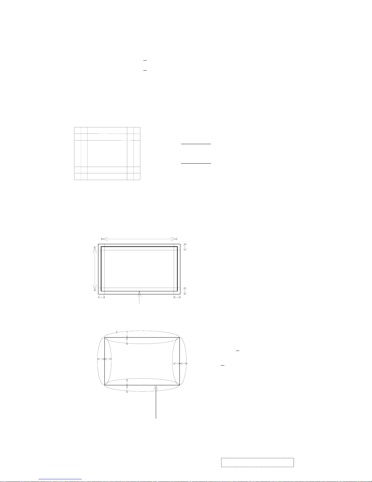
4.6 LINEARITY
12 x 10
INPUT SIGNAL : BLOCK PATTERN
V-LINEARITY :
Xmax
Xmax
Ymax
Ymax
Xmin
Ymin
Ymin
Xmin
X 100%
H-LINEARITY:
X 100%
+
-
+
-
< 4%
< 4%
; WORSE CASE < 5%
4.7 PICTURE DISTORTION
4.7.1 TRAPEZOID / PARALLELOGRAM
4.7.2 PINCUSHION / BARREL / PIN-BALANCE
PICTURE
2mm
268mm
357mm
TRAPEZOID:
HORIZONTAL <= 2mm
VERTICAL <= 2mm
PARALLEL <= 2mm
2mm
2mm
2mm
'
'
C'
PICTURE
PINCUSHION <
BARLEL <
1.5mm
C
6
ViewSonic Corporation Confidential
-
Do Not Copy A91f+-1
Page 10
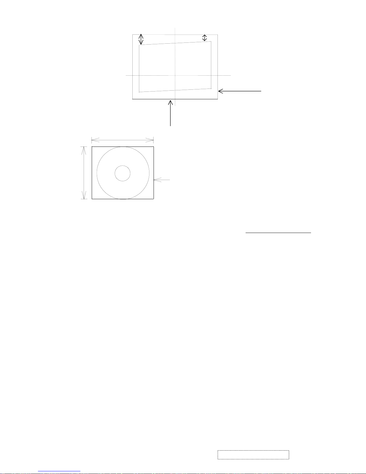
4.7.3 TILT
D
A
B
A - B <= 2mm
.
BEZEL
4.8 MISCONVERGENCE
4.9 FOCUS
4.9.1 UNDER THE CONDITION OF BRIGHTNESS CENTER AND CONTRAST MAXIMUM
“ ME “ PATTERN CAN BE SEEN CLEARLY BY USING THE 1280X1024 69 KHZ/85HZ
IF
NECESSARY, LIMIT SAMPLE AGREED BY BOTH PARTIES WILL BE MADE FOR
FINAL FOCUS JUDGMENT.
4.10 JITTERS
4.10.1 NO VISIBLE
4.11 WHITE BALANCE
4.11.1 COLOR TEMPERATURE USING THE CIE COLOR TEMPERATURE COORDINATE
SYSTEM
COLOR 9300
O
K X = 0.283±0.015; Y = 0.297±0.015
COLOR 6500
O
K X = 0.313±0.020; Y = 0.329±0.020
COLOR 5000
O
K X = 0.346±0.020; Y = 0.359±0.020
PICTURE
357mm
268mm
ZONE A <= 0.25mm
ZONE B <= 0.30mm
B
ZONE C <= 0.35mm
C
A
4.11.2 COLOR PURITY IMPURITY SHOULD NOT APPEAR IN THE PATTERN OF ALL
GREEN ALL RED ALL BLUE OR ALL WHITE
4.11.3 COLOR TRACKING: WHEN THE FULL WHITE PATTERN IS DISPLAYED AT PRESET
(ONLY FOR 9300
O
K) CONDITION. THE DIFFERENCE OF WHITE BALANCE
BETWEEN CONTRAST 30 FL AND LOW CONTRAST 10 FL MUST BE LESS THAN
FOLLOWING VALUE
x AT CONTRAST 30 FL - x AT 25.75 FL < 0.005
y AT CONTRAST 30 FL - y AT 25.75 FL < 0.005
AND: x AT CONTRAST 25.75 FL - x AT 10 FL < 0.009
Y AT CONTRAST 25.75 FL - Y AT 10 FL < 0.009
4.11.4 VIDEO AMPLIFIER LINEARITY INPUT STEP AT 9300
O
K
x 600mV – x 700mV < 0.007
y 600mV – y 700mV < 0.003
7
ViewSonic Corporation Confidential
-
Do Not Copy A91f+-1
Page 11
4.12 LIGHT OUTPUT
AT 80 KHZ 1280X1024/75HZ MODE.
4.12.1 LL => AT BLACK PATTERN = 0.4 -1.2FL AT BRIGHTNESS 100%, CONTRAST 0%
FOR 9300
O
K
4.12.2 HL => AT WHITE BLOCK PATTERN = 37-43
FL AT BRIGHTNESS 50%, CONTRAST
100% FOR 9300
O
K
4.12.3 ABL => AT FULL-WHITE PATTERN 28-32
FL, BRIGHTNESS 50%, CONTRAST
100% FOR 9300
O
K
4.13 BRIGHTNESS UNIFORMITY
4.13.1 > 75
% MAXIMUM BETWEEN CENTER TO ANY EIGHT POINTS WITHIN THE
DISPLAY PICTURE FULL WHITE PATTERN
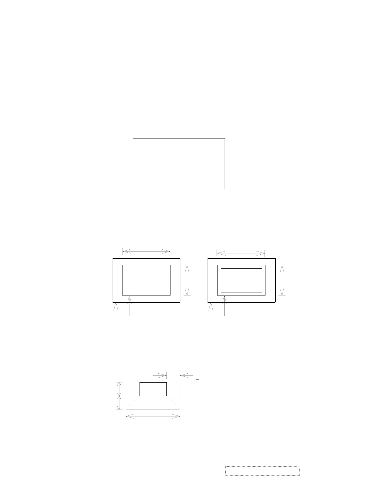
4.14 SIZE REGULATION
4.14.1 STATIC REGULATION
PICTURE GROWTH FROM MINIMUM LIGHT OUTPUT TO MAXIMUM LIGHT OUTPUT
SHALL BE LESS THAN 3mm WHEN PICTURE IS EXCHANGED FROM
4.14.2 DYNAMIC REGULATION
PICTURE GROWTH SHALL BE LESS THAN 1 mm WHEN PICTURE IS EXCHANGED FROM
A
D
F
BC
E
HG
CENTER
PICTURE
BEZEL
BLACK WHITE
A
B
A'
B`
PICTURE
BEZEL
370mm
WHITE
BLACK100mm
100mm
< 1 mm
8
ViewSonic Corporation Confidential
-
Do Not Copy A91f+-1
Page 12

5. ENVIRONMENTAL CONDITIONS
5.1 TEMPERATURE AND HUMIDITY AT OPERATION 0 ~ 40 ° C
5 – 95 % RH WITHOUT CONDENSATION
5.2 TEMPERATURE AND HUMIDITY AT STORAGE - 40 ~ 60
°
C
10 – 95 % RH LESS THAN
6
MONTH
5.3 VIBRATION TEST (PACKAGED)
FREQUENCY 5HZ –250 HZ – 5HZ
ACCELERATION 1.0G
SWEEP TIME 1 OCT/MIN.
TEST TIME 60MIN. / AXIS
5.4 DROP TEST (PACKAGED) 61 CM HEIGHT WEAK CORNER, 3 EDGES, 6 FACES, 1 TIME ON
EACH TESTED UNIT, 4 SETS MIN. DROP QTY.
5.5 ALTITUDE
OPERATING 0~3000 METERS.
NON-OPERATING 0~12000 METERS.
6. PHYSICAL SPECIFICATION
6.1 DIMENSION
HEIGHT: 457 mm
WIDTH 445 mm
DEPTH 456 mm
MONITOR WEIGHT 19.2 KG.
6.2 MECHANICAL ADJUSTMENT
TILT - 5/+15 DEGREES
SWIVEL ± 90 DEGREES
6.3 PACKAGING
6.3.1 CARTON DIMENSION
HEIGHT 498 mm
WIDTH 557 mm
DEPTH 577 mm
6.3.2 SHIPPING WEIGHT 22.4 KG
6.3.3 CONTAINER LOADING 320 UNITS WITH PALLET
9
ViewSonic Corporation Confidential
-
Do Not Copy A91f+-1
Page 13
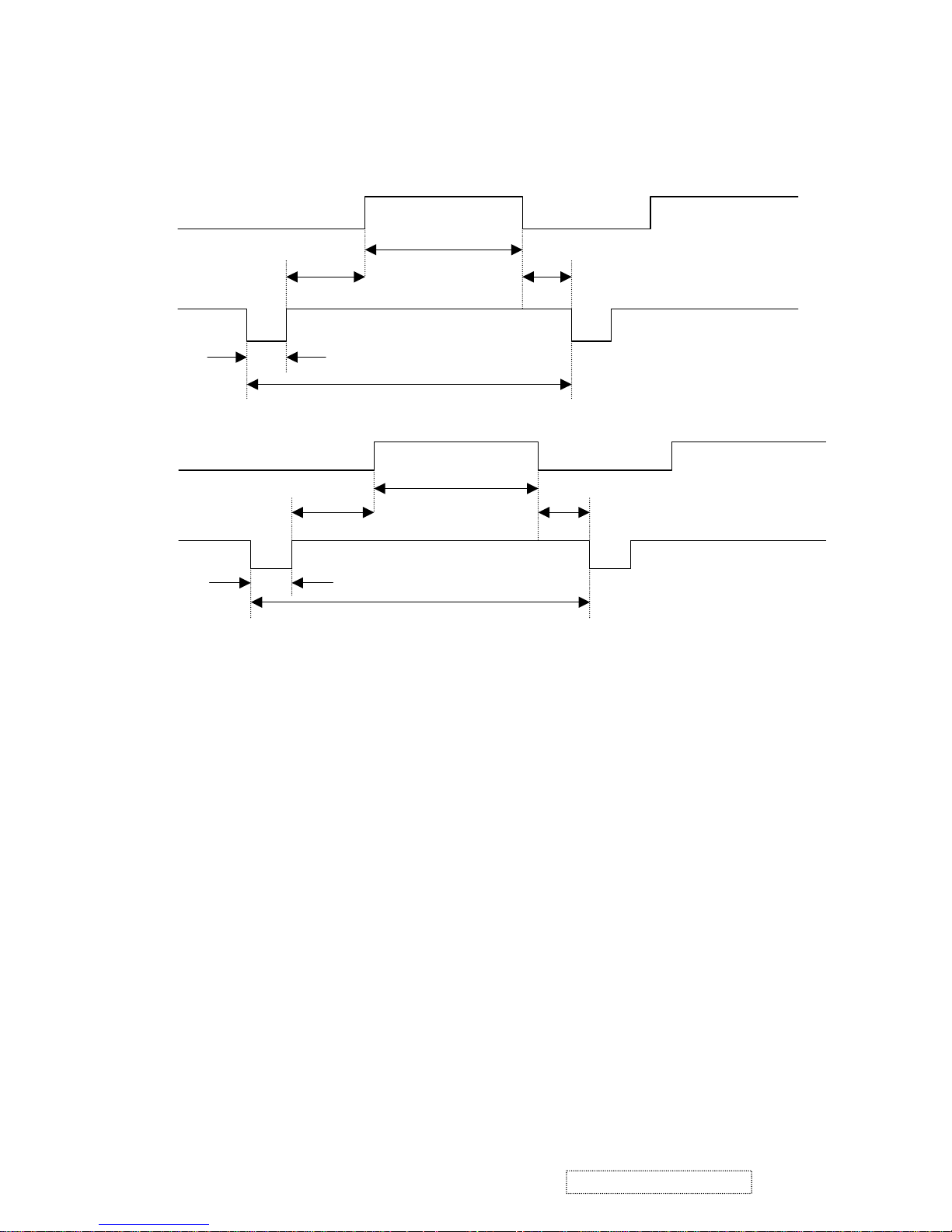
7. FACTORY PRESET TIMINGS
7.1 TIMING DIAGRAM
TIMING OF INPUT SIGNALS NOMINAL INPUT LEVEL SPECIFICATION.
INPUT LEVEL
ANALOG VIDEO
RGB: 0.7V ± 3db
SYNC: H.V. SEPARATE SYNC
TTL COMPATIBLE H.V. COMPOSITA SYNC
LOW (0) 0V MIN. 0.65V MAX.
HIGH (1) 2.40V MIN. 3.5V NOM. 5.5V MAX.
TIMING OF INPUT SIGNALS
A: H-TOTAL TIME O: V-TOTAL TIME
B: H-SYNC PULSE WIDTH P: V-SYNC PULSE WIDTH
C: H-BACK PORCH Q: V-BACK PROCH
D: H-DISPLAY TIME R: V-DISPLAY TIME
E: H-FRONT PORCH S: V-FRONT PORCH
VIDEO
C
D
E
B
A
VIDEO
Q
R
S
P
O
VERTICAL
10
ViewSonic Corporation Confidential
-
Do Not Copy A91f+-1
Page 14

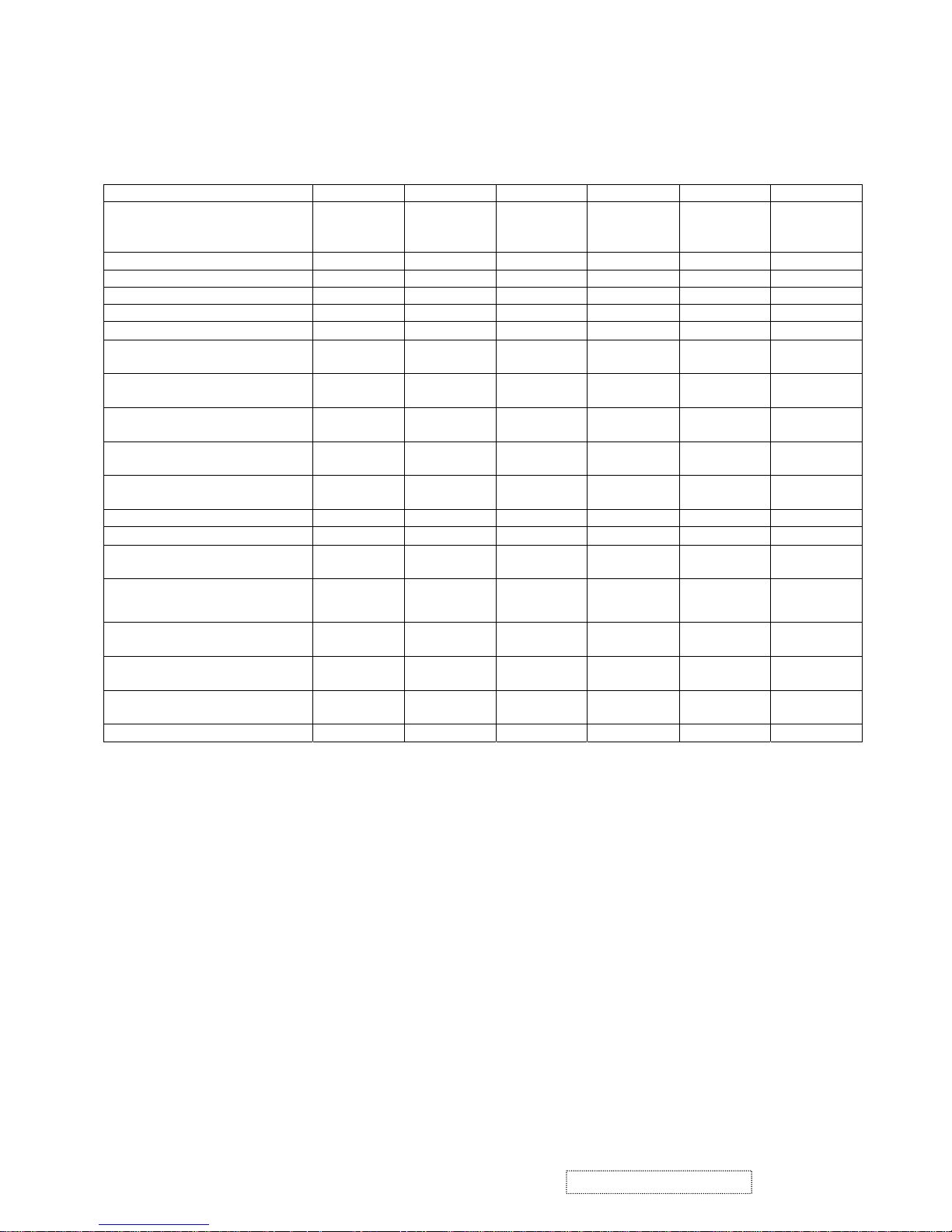
7.2 PRESET TIMING TABLE
PRESET TIMING TABLE
MODE NO. 1 2 3 4 5 6 7
MODE NAME
VGA
640X
480
VGA
640X
400
VGA
640X
480
VESA
800X
600
VESA
1024X
768
VESA
800X
600
VESA
1024X
768
HORIZONTAL DOTS 640 640 640 800 1024 800 1024
VERTICAL LINES 480 400 480 600 768 600 768
PIXEL CLOCK (MHZ) 25.175 25.175 36.00 49.5 65.000 56.25 78.75
HORIZONTAL FREQ (KHZ) 31.47 31.47 43.269 46.875 48.360 53.674 60.023
SYNC. POLARITY - - - + - +
+
A H.TOTAL (US)
(PIXELS)
31.778
(800)
31.778
(800)
23.111
(832)
21.333
(1056)
20.680
(1344)
18.631
(1048)
16.660
(1312)
B H.SYNC (US)
(PIXELS)
3.813
(96)
3.813 (96) 1.556
(56)
1.616
(80)
2.09
(136)
1.183 (64) 1.129
(96)
C H.SYNC PORCH (US)
(PIXELS)
1.907
(48)
1.907 (48) 2.222
(80)
3.232
(160)
2.460
(160)
2.702 (152) 2.235
(176)
D H.ACTIVE (US)
(PIXELS)
25.422
(640)
25.422
(640)
17.778
(640)
16.162
(800)
15.75
(1024)
14.222
(800)
13.003
(1024)
E H.FRONT PORCH (US)
(PIXELS)
0.636
(16)
0.318 (8) 1.556
(56)
0.323
(16)
0.370
(24)
0 (0) 0.203
(16)
VERTICAL FREQ (HZ) 59.94 70 85.008 75.00 60.000 85 75.029
SYNC. POLARITY - + - + - +
+
O V.TOTAL (MS)
(LINES)
16.684
(525)
14.268
(449)
11.764
(509)
13.333
(625)
16.670
(806)
11.756
(631)
13.328
(800)
P V.SYNC (MS)
(LINES)
0.064
(2)
0.064 (2) 0.069
(3)
0.064
(3)
0.12
(6)
0.056 (3) 0.050
(3)
Q V.BACK PORCH (MS)
(LINES)
1.048
(33)
1.112 (35) 0.578
(25)
0.448
(21)
0.600
(29)
0.503 (27) 0.466
(28)
R V.ACTIVE (MS)
(LINES)
15.254
(480)
12.711
(400)
11.093
(480)
12.800
(600)
15.880
(768)
11.179
(600)
12.795
(768)
S V.FRONT PORCH (MS)
(LINES)
0.318
(10)
0.222 (7) 0.023
(1)
0.021
(1)
0.06
(3)
0
(0)
0.017
(1)
SCANTYPE INTERLACED NO NO NO NO NO NO NO
11
ViewSonic Corporation Confidential
-
Do Not Copy A91f+-1
Page 15
PRESET TIMING TABLE (CONTINOUS)
MODE NO. 8 9 10 11 12 13
MODE NAME
VESA
1024X
768
VESA
1280X
1024
VESA
1600X
1200
MAC
640X
480
MAC
832X
624
MAC
1024X
768
HORIZONTAL DOTS 1024 1280 1600 640 832 1024
VERTICAL LINES 768 1024 1200 480 624 768
PIXEL CLOCK (MHZ) 94.5 135.00 162 30.240 57.270 80
HORIZONTAL FREQ (KHZ) 68.677 79.976 75.000 35.000 49.717 60.241
SYNC. POLARITY +
+ + −
-
−
A H.TOTAL (US)
(PIXELS)
14.561
(1376)
12.504
(1688)
13.333
(2160)
28.571
(864)
20.115
(1152)
16.600
(1328)
B H.SYNC (US)
(PIXELS)
1.016 (96) 1.067
(144)
1.185
(192)
2.116
(64)
1.118 (64) 1.200
(96)
C H.SYNC PORCH (US)
(PIXELS)
2.201 (208) 1.837
(248)
1.877
(304)
3.175
(96)
3.911 (224) 2.20
(176)
D H.ACTIVE (US)
(PIXELS)
10.836
(1024)
9.481
(1280)
9.877
(1600)
21.164
(640)
14.528 (832) 12.8
(1024)
E H.FRONT PORCH (US)
(PIXELS)
0 (0) 0.119
(16)
0.395
(64)
2.116
(64)
0 (0) 0.4
(32)
VERTICAL FREQ (HZ) 85 75.025 60.00 66.667 74.55 74.927
SYNC. POLARITY +
+
+
−
-
−
O V.TOTAL (MS)
(LINES)
11.765 (808) 13.329
(1066)
16.667
(1250)
15.000
(525)
13.417 (667) 13.346
(804)
P V.SYNC (MS)
(LINES)
0.044 (3) 0.038
(3)
0.04
(3)
0.086
(3)
0.060 (3) 0.050
(3)
Q V.BACK PORCH (MS)
(LINES)
0.524 (36) 0.475
(38)
0.613
(46)
1.114
(39)
0.784 (39) 0.498
(30)
R V.ACTIVE (MS)
(LINES)
11.183 (768) 12.804
(1024)
16.000
(1200)
13.714
(480)
12.552 (624) 12.749
(768)
S V.FRONT PORCH (MS)
(LINES)
0 (0) 0.013
(1)
0.013
(1)
0.086
(3)
0(0) 0.05
(3)
SCANTYPE INTERLACED NO NO NO NO NO NO
12
ViewSonic Corporation Confidential
-
Do Not Copy A91f+-1
Page 16

EDID DATA for SAMSUNG CRT
:
TIME: 09:20:50
DATE: FEB 12, 2004
VIEWSONIC CORPORATION
EDID VERSION # 1, REVISION # 3
DDCTEST FOR: VIEWSONIC A91F+
128 BYTES OF EDID CODE FOR SAMSUNG CRT
_____________________________________________________
0 1 2 3 4 5 6 7 8 9
________________________________________
0 | 00 FF FF FF FF FF FF 00 5A 63
10 | 19 9E 01 01 01 01 01 0E 01 03
20 | 1D 24 1B BE 2A BB B8 A3 52 46
30 | 98 24 0F 48 4C FF FF 80 81 80
40 | C1 40 A9 40 81 40 71 4F 61 59
50 | 45 59 31 59 BC 34 00 98 51 00
60 | 2A 40 10 90 13 00 60 08 11 00
70 | 00 1E 00 00 00 FF 00 50 35 31
80 | 30 34 30 31 30 30 30 30 31 0A
90 | 00 00 00 FD 00 32 B4 1E 56 14
100 |
00 0A 20 20 20 20 2 0 20 00 00
110 | 00 FC 00 41 39 31 66 2B 0A 20
120 |
20 20 20 20 20 20 00 05
___________________ _______________________________
EDID DATA for LG CRT:
TIME: 09:45:14
DATE: FEB 12, 2004
VIEWSONIC CORPORATION
EDID VERSION # 1, REVISION # 3
DDCTEST FOR: VIEWSONIC A91F+
128 BYTES OF EDID CODE FOR LG CRT
_____________________________________________________
0 1 2 3 4 5 6 7 8 9
________________________________________
0 | 00 FF FF FF FF FF FF 00 5A 63
10 | 19 9E 01 01 01 01 01 0E 01 03
20 | 1D 24 1B CE 2A 05 78 A0 56 4A
30 | 99 26 12 48 4C FF FF 80 81 80
40 | C1 40 A9 40 81 40 71 4F 61 59
50 | 45 59 31 59 BC 34 00 98 51 00
60 | 2A 40 10 90 13 00 60 08 11 00
70 | 00 1E 00 00 00 FF 00 50 35 31
80 | 30 34 30 31 30 30 30 30 31 0A
90 | 00 00 00 FD 00 32 B4 1E 56 14
100 | 00 0A 20 20 20 20 20 20 00 00
110 | 00 FC 00 41 39 31 66 2B 0A 20
120 | 20 20 20 20 20 20 00 E0
____
__ __ __
___________________ _______________________________
13
ViewSonic Corporation Confidential
-
Do Not Copy A91f+-1
Page 17
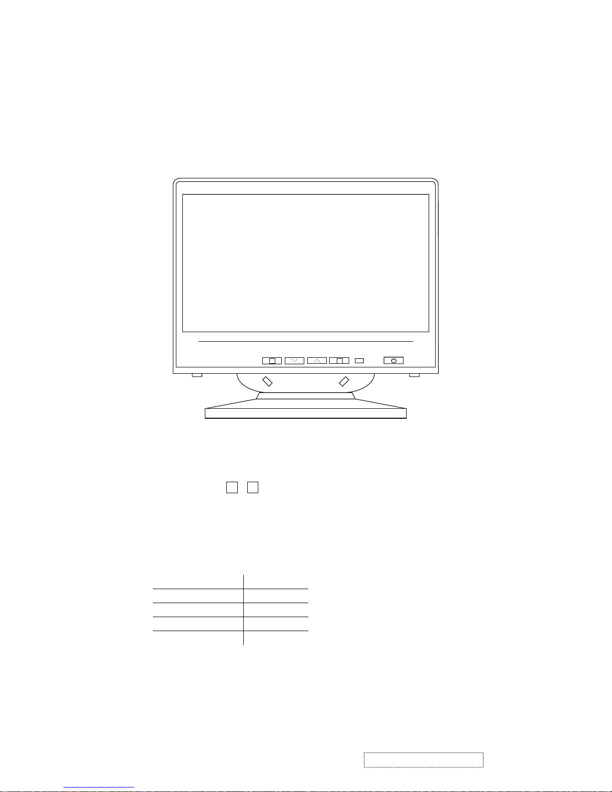
Control function﹒
A﹒User control﹒
B﹒OSD function control﹒
1 2
3. Front Panel Function Control Description
A﹒User control﹒
Power switch:Soft power control﹒
Function select button: , ﹒
Adjustment control button
:▽﹑△﹒
Control name﹒
1﹒Power switch:Push-on / push-off switch for soft power control﹒
2﹒LED indication﹒
Status LED
Power on Green
Off mode in 5 sec Orange
Over range freq. Orange
Power off Off
1
2
14
ViewSonic Corporation Confidential
-
Do Not Copy A91f+-1
Page 18
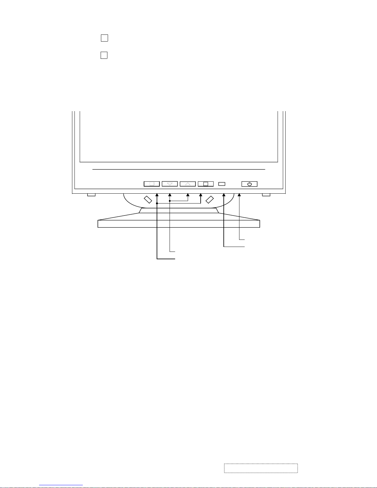
3﹒Function select button:
Press the ‘ ’ button to display OSD menu﹒
Press the ‘
▽﹑△
’ button to select menu function or sub-function﹒
Press the ‘ ’ button to enter the select function﹒
4﹒Adjustment control button:
Push the increased ‘△’ or decrease ‘▽’ button for the desired adjustment﹐all adjustment are memorized
automatically immediately﹒
Function select buttons
Adjustment control buttons
Power switcha.
b.
c.
d.
Power-ON indication
1
2
1
2
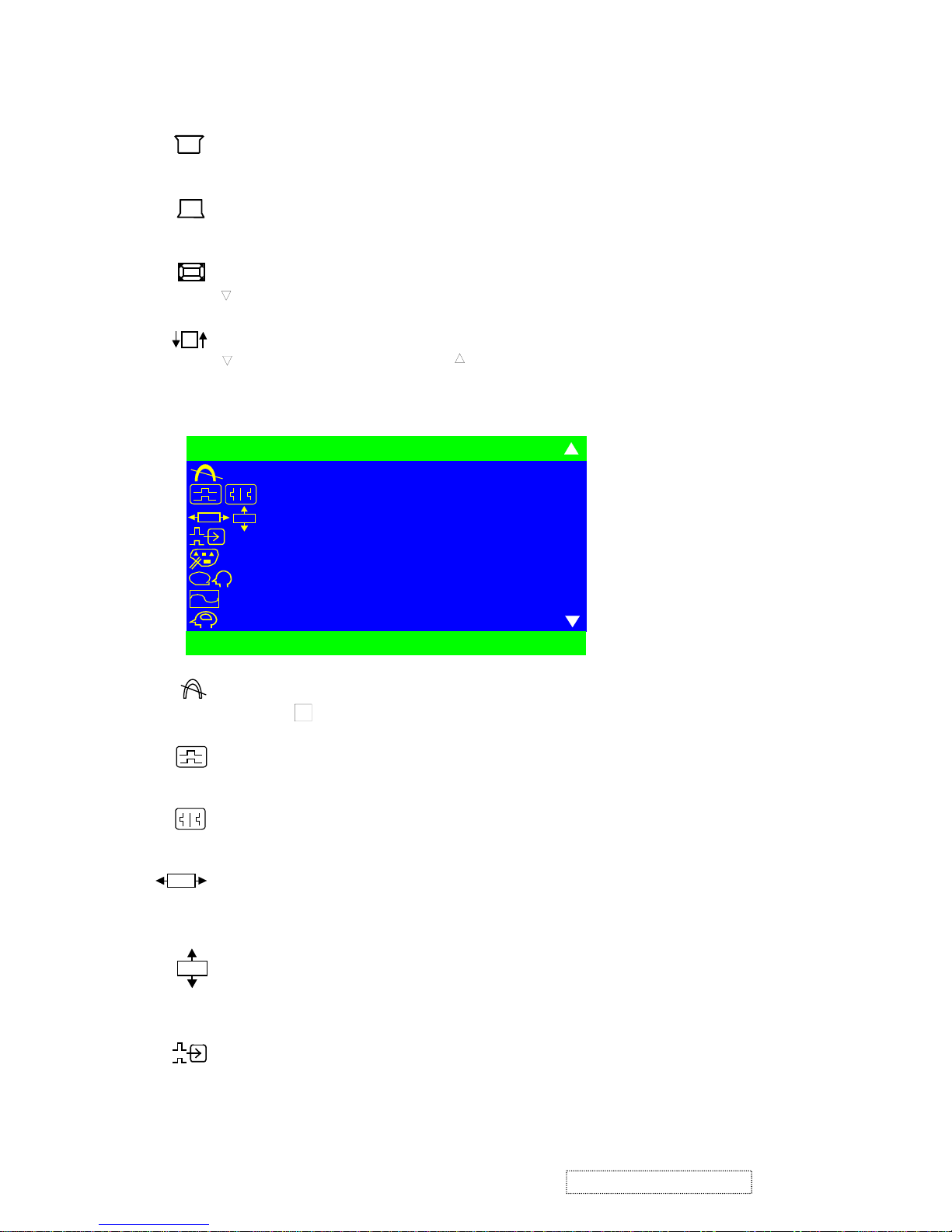
B. OSD (on screen display) function control method.
. Main menu, Part 1.
1. Contrast / Brightness.
2. H. size / Position.
3. V. size / Position.
4. Pincushion / Balance.
5. Trapezoid / Parallel.
6. Top/Bttom Hook.
7. ZOOM
8. Tilt
. Main menu, Part 2.
9. Degauss
10. H/V Moire.
11. OSD Position.
12. Input Level.
13. View match color.
14. Language.
15. View meter.
16. Memory Recall.
15
ViewSonic Corporation Confidential
-
Do Not Copy A91f+-1
Page 19
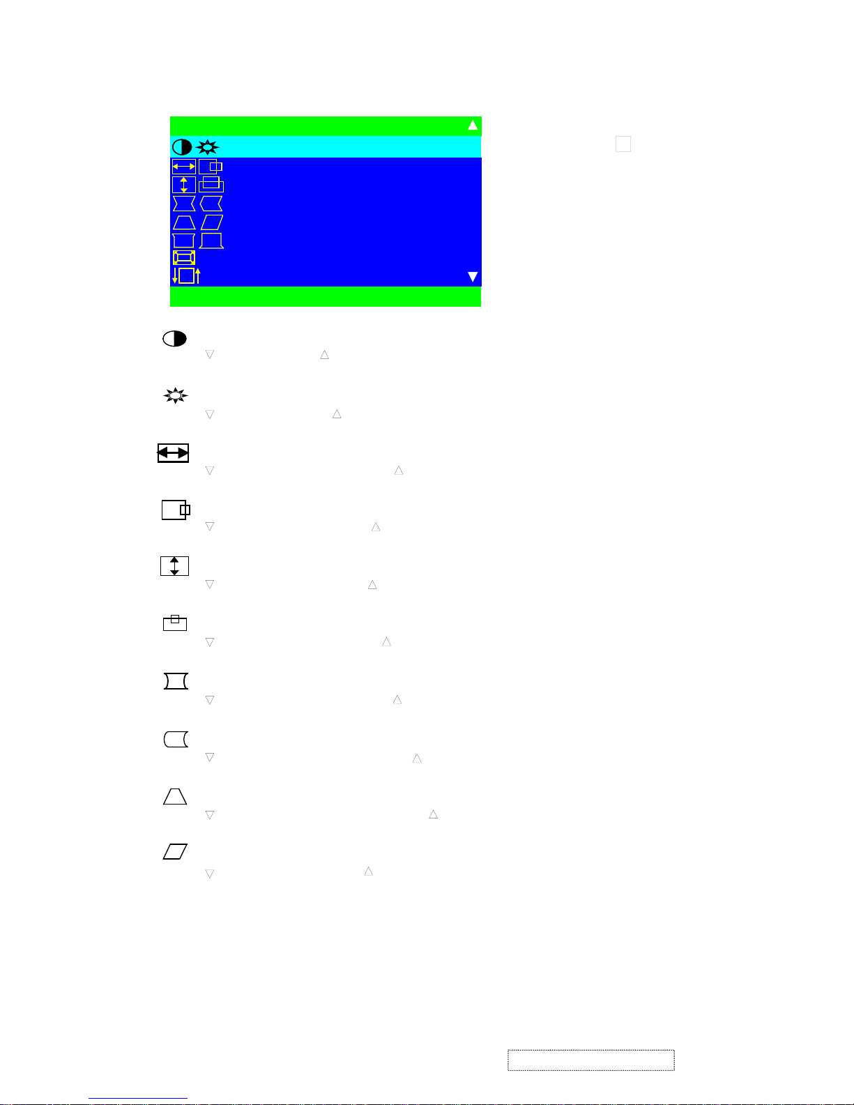
OSD function control :
Main menu, part1
Note
:
Press button to toggle between
all Controls that appear in pairs on the
Main menu1.
Contrast adjusts the foreground white level of the screen image.
decreases contrast, increases contrast.
Brightness adjusts the background brightness of the screen image.
decreases brightness, increases brightness.
HORIZONTAL SIZE adjusts the width of the screen image.
decreases width of screen image, increases width of screen image.
HORIZONTAL POSITION moves the screen image left or right.
moves the screen image left, moves the screen image right.
VERTICAL SIZE
adjusts the height of the screen image.
decreases the screen height, increases the screen height.
VERTICAL POSITION moves the screen image up and down.
moves the screen image down, moves the screen image up.
PINCUSHION straightens the vertical sides of the screen image by curving them inward or out ward.
curves the vertical edges inward, curves the vertical edges outward.
PIN BALANCE straightens the vertical sides of the screen image by curving them to the right or to the left.
scurves the vertical edges to the left, curves the vertical edges to the right.
TRAPEZOID make vertical sides of the screen image parallel.
narrows the top and widens the bottom, widens the top and narrows the bottom.
PARALLEL (parallelogram) slants vertical edges of the screen to the left or right.
slants vertical edges to left, slants vertical edges to right.
2
MA I N ME N U 1
CONTRAST / BR I GHTNESS
H.SI ZE/POSI TION
V.SIZE/POSITION
P I NCUSH I ON / BA L ANCE
TRAPEZO I D / PARALLEL
TOP / BOT T OM HOOK
ZOOM
TILT
EX I T : 1 SELECT :2
16
ViewSonic Corporation Confidential
-
Do Not Copy A91f+-1
Page 20
TOP HOOK
Straightens the top corners of the screen image. [▽] or [△] to adjust.
BOTTOM HOOK
Straightens the bottom corners of the screen image. [▽] or [△] to adjust.
ZOOM CONTROL
to diminish H-Size
& V-Size, △ to enlarge H-Size & V-Size.
TILT
rotates the entire screen image.
rotates the screen counter-clockwise, rotates the screen clockwise.
Main menu, part12
MA I N MEN U 2
DEGAUSS
H/V MOIRE
OSD POS I T I ON
I NPUT LEVEL
VIEWMATCH COLOR
LANGUAGE
VIEWMETER
MEMORY RECAL L
EX I T : 1 SELECT : 2
OSD
OSD
?
DEGAUSS manual degauss function.
Press button to active manual degauss function.
H MOIRE reduces vertical interference that causes unwanted color textures or patterns.
Press
▽
or △ to adjust.
V MOIRE reduces horizontal interference patterns that causes unwanted color textures or patterns.
Press
▽
or △ to adjust.
OSD H-Position control
Press the
▽, △ button.
▽ move OSD to left side, △ move OSD to right side﹒
OSD V-Position control
Press the ▽, △ button.
△
move OSD to up, ▽ move OSD to down.
INPUT LEVEL displays the voltage level of the video signal.
2
OSD
OSD
17
ViewSonic Corporation Confidential
-
Do Not Copy A91f+-1
Page 21
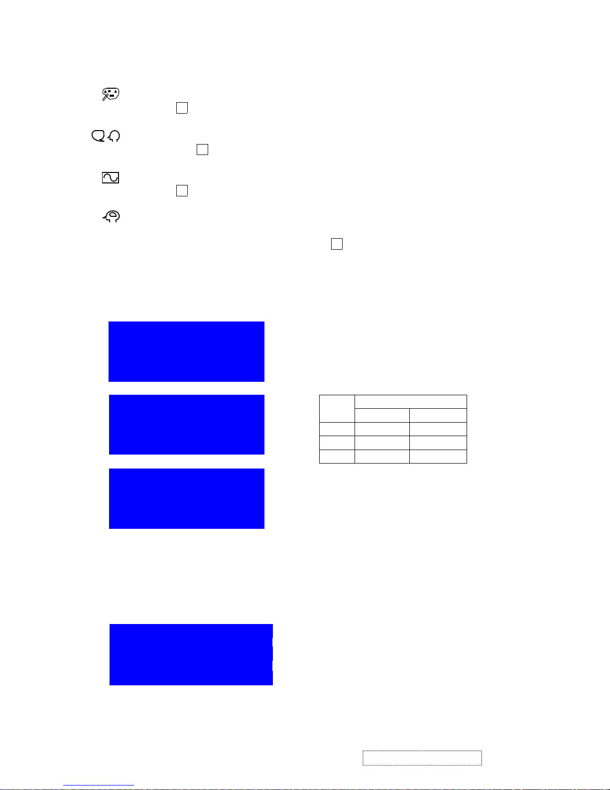
VIEWMATCH COLOR provides three color adjustment modes : 9300oK, 6500oK, 5000 oK and User.
Press button to select color adjustment mode.
LANGUAGE to select a language use
▽
and △ to highlight English, French, German, Italian, or Spanish,
Then press button .
VIEWMETER displays the signal input coming from your computer (horizontal scan and refresh rate).
Press button to select this feature.
MEMORY RECALL
returns adjustment back to factory setting only if the monitor is operating in a factory
preset mode.
If you make an adjustment you don’t like, press button to recall factory setting.
DIAGNOSTIC MESSAGE:
1.If monitor into DPMS mode will show:
Display Time : 5 seconds
Back ground : Blue
Characters
: White
Horizontal
2.If input V-sync or H-sync out of pull-in range will show:
H:30KHz ~ 86KHz V:50Hz ~ 180Hz
Display Time
Pull-in range
H . V FREQUENCY
Back ground
: Blue
OVER RANGE
Characters : White
Off Pulses
No Pulses
Off
No Pulses
No Pulses
Mode
Signals
Vertical
Off
No Pulses
Pulses
: 25 seconds
:
Off mode in 5 sec
OFF MODE IN 5 SEC
OFF MODE IN 5 SEC
OFF MODE IN 5 SEC
2
2
?
2
2
18
ViewSonic Corporation Confidential
-
Do Not Copy A91f+-1
Page 22
1﹒ POWER SUPPLY﹒
1.1 Power supply﹒
A﹒ Primary Side﹒
The raw DC voltage is built on C101 from AC line voltage through EMI filter﹐and bridge rectifier CR101﹐then
composes with main transformer(T101)﹐switching MOSFET(Q101)and PWM IC(IC101)to form a DC-DC
voltage converter by fly back switching topology, which means that the power energy is pumped up at primary
winding of transformer during duty “ON” cycle﹐then transfer the stored energy to primary side﹐and voltage
regulated by PWM IC(3842)using way of pulse width modulation﹒
The IC101 starts up through some components composed of R103﹐R104﹐R105﹐Q102﹐ZD101 D110.R118.
R107 to build up VCC voltage at pin7﹐and supplied by transformer once secondary voltage is established﹒
IC101 have to work synchronously with horizontal sync by feeding fly back pulse through C110﹒
R124 .R125, C112 and D114 composed a soft-start circuit to prevent over-stress occurred during power start﹒
The TP202:40V voltage can be adjusted through VR101﹒
B﹒ Secondary﹒
Each raw of DC voltage output from T101﹒
a﹒ TP201 voltage output from T101 pin9 and is rectified by D202﹐C201﹒
b﹒ TP202 voltage output from T101 pin14 and is rectified by D203﹐D214. C202﹒
c﹒ TP203 voltage output from T101 pin15 and is received by D205﹐C205﹒
d﹒ TP204 voltage output from T101 pin16 and is rectified by D206﹐C206﹒
e﹒ TP205 voltage output from T101 Pin15 and is rectified by Q206﹐ZD201 and D208.C210. ﹒
f﹒ TP206 voltage output from TP204 and is rectified by Q208.Q209.﹐R214. R215.and R213﹒
g﹒ TP207 voltage output from T204﹒and is rectified by Q210 ZD202 D209 R217.C211and C212.
1.2 Power saving﹒
The EPA power management state as follows:
State SUS Pd Power consummation LED
Normal H H 110W Green
Active off L L ≤ 5W Amber
SUS = IC301(MCU)pin17 output﹒
PD = IC301(MCU)pin18 output﹒
There is no output from Q206 and Q203 while is in Active off mode and SUS(IC301 pin17)and PD
(IC301 pin18)are at low level voltage﹒That is, there is no output for 12V and 6.3V﹒
1.3 Degauss﹒
When the powers is on and when press manual degauss﹐IC301 pin20 output high level voltage to turn on
Q201﹐RL101 and activate Degauss﹒
4. Circuit Description
19
ViewSonic Corporation Confidential
-
Do Not Copy A91f+-1
Page 23

2﹒ VERTICAL﹒
2.1 Auto SYNC Deflection control and B+ control circuit Horizontal and vertical sync through IC401 TDA9113
transmit﹒
Deflection controller IC401 TDA9113:
a﹒ The control input(V-position﹐H-position﹐V-s iz e﹐H-size﹐Pincushion﹐Pin-Balance﹐Trapezoid﹐
Parallelogram. TOP Corner. Bottom Corner. Zoom, moiré)are use I
2
C control﹒
b﹒ SYNC input:
H-sync(pin1)(From IC301 pin33)﹒
V-sync(pin2)(From IC301 pin32)﹒
c﹒ Output:
∗ B
+
Driver(pin28)﹒
∗ H-Driver(pin26)﹒
∗ EW-Driver(pin24)﹒
∗ Focus(pin32)﹒
∗ V out(pin23)﹒
2.1.1 Horizontal﹒
a﹒ Then take a HFLB pulse from horizontal output Q407 collector C418 and C419 mid voltage to
IC401 for AFC to make pin12 control H-Drive﹒
b﹒ Pin5 and pin6(C410﹐R410)control horizontal hold in range﹒
2.1.2 Vertical﹒
a. V-sync outputs from MCU IC301 pin32 to IC401 pin2﹐then than smite from pin23﹐pin 13 to
IC501 TDA8172 pin1and pin7﹒
b. IC401 pin3﹐pin7 outputs to vertical hold in range is controlled by pin22(C440)﹒
2.1.3 B
+
control﹒
Take a pulse from T403 pin2 and accumulates to become a DC voltage via Q409﹐Q401.Q402.
R418 ,and .R424 to IC 401 pin 28. (Step up circuit control).
2.2 Vertical deflection﹒
a﹒ IC401 pin23 and pin13 output to IC501(TDA8172)pin7 and pin1﹐then IC501 pin5 and pin7 make
vertical deflection output﹒
b﹒ Vertical blank:IC501 pin3 take a blanking pulse﹐After passing Q501 buffer can supply video blanking
signal﹒
2.3 Boost converter﹒
The Booster converter mainly composes of n-channel MOSFET Q409 Transformer T403 capacitor C442 and
rectifier diode D408. IC401 pin28 B
+
driver output via Q401, Q402, to driver Booster converter
and provide a DC-voltage to provide B
+
H-output circuit use﹐As H-freq. change﹐IC401 pin28 B+-driver
will change its output﹐Booster converter will also change the B
+
it provides﹐H-freq. will varies from
30K ~ 86KHz﹐B+ will varies from 40V ~ 180V﹒
20
ViewSonic Corporation Confidential
-
Do Not Copy A91f+-1
Page 24

2.4 X-RAY radiation protection﹒
FBT pin6 output one pulse to pass through D4407.ZD4403 .D4408 and C4420 integration DC voltage﹐and
through D4420.Q4404.IC402.pin 2﹐when anode voltage abnormal increase﹐FBT pin6 and IC402 pin2 voltage
to be increased﹐too﹒
As IC402 pin2 ≅0.6V﹐IC402 X-RAY protection circuit immediately active﹐High voltage to shut-down﹒
The X-RAY radiation protection circuit used in this monitor is a latching type the monitor will shown down
and continue until turn-off the monitor with power switch﹒
3﹒ Horizontal﹒
3.1 Horizontal driver circuit﹒
The output of IC401 pin26 H-Driver connect to Q403.Q404 H-Buffer transistor makes The Q403.Q404 push
pull output to Q406 H-driver, push H-output Q407 to reach secondary via induction of T4401﹒For T4401 is a
Transformer of reduced voltage and converted pole﹐Q407 will be turn off when Q406 is on﹐on the contrary﹐
went Q406 is turn off and Q407 will be on﹒
3.2 Horizontal output circuit﹒
Horizontal output circuit is composed by Q407(Horizontal Transistor)﹐CRT YOKE.D406.C418 and C419.
H-output circuit﹐H-Driver circuit output via T4401to switch Q407 ON/OFF to output saw tooth wave and make
DY able to control the circuit scanning of elections in the CRT﹒
L403﹐L404﹐C427﹐C432﹐C428 and C429 modify Horizontal linearity switching individually Dai RL401﹐
Q415﹐Q411﹒
3.3 EW-Pincushion and width control circuit
The parabolic waveform and DC voltage and generated from IC401 pin24 to Q405, R421, R422 to IC401
pin15﹒
The parabolic decreased or increased for compensating the pincushion effect the DC voltage control the
H-width﹒
3.4 High-voltage circuit
High-voltage circuit is composed by Q4401.T401 (FBT) and.C4406 .High-voltage output stage .
The IC 402 is PWM duty-cycle control.
1. Q4405 High voltage buffer stage.
2. Q4401 High voltage output stage.
3. Q4402 PWM control Driver stage.
4. Q4407.Q4408 .and Q4410 Brightness control circuit .
5. Q4406 D4426.R4429.R4430.VR4402 andC4427. ABL control circuit.
6. VR4401 High voltage control.
7. VR4402 ABL Lever control.
21
ViewSonic Corporation Confidential
-
Do Not Copy A91f+-1
Page 25

4﹒ Video﹒
4.1 Video amplifier(IC601)﹒
The video amplifier module is composed of three amplifiers for Red﹐Green﹐Blue channel﹒
The video input signal is fed to the video preamplifier IC601(KA2500)pin8 Red﹐pin5 Green﹐pin10 Blue﹐
through AC coupling capacitor﹐C601﹐C601﹐C603﹒
The clamping pulse comes from IC301 pin33﹒
IC603 output amplifier for B﹑R﹑G channel respectively﹒
4.2 On Screen Display(OSD)(IC602)﹒
IC602(NT6827-0047)is a on screen display generator, pin5 for H-sync input﹐pin10 for V- sync input﹒
The IC602 is controlled by IC301 via SCL﹐SDA bus IC602(pin7﹐pin8)﹒
The on screen display signal is output from pin15(r)﹐pin14(g)﹐pin13(b)and OSD BLK to IC601 pin2﹐
pin1﹐pin3﹐pin4﹒
4.3 Auto Beam Limit CKT(ABL CKT)﹒
When beam current pass through VR4402 over 500uA﹐the voltage build at base of Q4406 will be low enough
to turn on Q4406﹐then the voltage of pin12 of IC601 will be pulled down accordingly to reduce the video
preamplifier gain output﹒
4.4 Brightness Control﹒
Brightness is controlled by varying the DC voltage of G1 with the IC301 PIN1(PWM)﹒
`
4.5 Blanking CKT﹒
IC501(TDA8172)pin3 vertical blanking pulse are fed to the base of Q501﹐The blanking pulse O/P is coupled
to G1 by C507﹒
Horizontal blanking pulse are fed to IC601 pin19 and let video O/P amp cut off during the period of horizontal
retrace﹐while mode change﹐IC301 pin19 will pull high to turn off﹒The G1 voltage will down to –180V then
CRT will cut off the video output﹒
5﹒ Tilt﹒
IC301 pin2 PWM to tilt circuit﹐Q211 and Q213 control flow of current of Rotation coil﹐when the base of C215
increase from 0 to 12V﹐As Q211 will turn on gradually﹐the current starts from 14V to 6.3V via Rotate coil﹒
When C215decrease from 12V to 0V﹐the current will change from 6.3V to GND﹒
22
ViewSonic Corporation Confidential
-
Do Not Copy A91f+-1
Page 26

6﹒ Micro(IC301)﹒
6.1 HS/VS Processor﹒
HS/VS input pin39(HS)﹐pin40(VS)﹐IC301 individually to work on frequency﹐polarity﹐process of H+V
and power saving﹐then output horizontal sync(pin33)and vertical sync(pin32)of positive polarity to
IC401 TDA9113 pin1﹐pin2﹒
6.2 PWM Control﹒
The PWM control of IC301 is pin1(Brightness) and pin3(Rotation)﹐the PWM output via R﹐C after
rectified may control each function﹒
6.3 Power saving / Mute / LED control﹒
IC301 pin17﹐pin18 are power saving control pin﹐the condition of power saving and mode change﹐pin19 will
change from Low to Hi and active Mute function﹒
Normal Active
Mute L H
SUS H L
(Off mode)
PD H L
(Off mode)
IC301 pin17(SUS)function as LED control﹐the mode is as listed:
Power On Power saving Over range freq﹒
Pin17 Hi Low Low
6.4 CS control(CS1 ~ CS3)﹒
To count H-SYNC by the output frequency﹐then output the cumulating as listed:
Freq. CS1 CS2 CS3
< 30K 1 0 0
30K~34K 1 0 0
34K~36.5K 1 1 0
36.5K~41K 1 1 1
41K~52K 0 0 0
52K~62K 0 0 1
62K~72K 0 1 0
> 72K 0 1 1
6.5 Key Control﹕IC301 pin26~pin29 function as DAC switch input to control OSD display function﹒
Pin26: ﹒
Pin27
:▽﹒
Pin28
:△﹒
Pin29: ﹒
6.6 I
2
C Bus﹒
IC301 have two groups I
2
C bus to control E2PROM﹐IC401 deflection IC﹐Auto aliment﹐IC601 pre-AMP﹐
IC602 OSD IC function﹒
1
2
23
ViewSonic Corporation Confidential
-
Do Not Copy A91f+-1
Page 27

(1) (2)
(3) (4)
(5) (6)
24
ViewSonic Corporation Confidential
-
Do Not Copy A91f+-1
Page 28

(7) (8)
(9) (10)
(11) (12)
25
ViewSonic Corporation Confidential
-
Do Not Copy A91f+-1
Page 29

(13) (14)
(15) (16)
(17) (18)
26
ViewSonic Corporation Confidential
-
Do Not Copy A91f+-1
Page 30

(19) (20)
(21) (22)
(23) (24)
27
ViewSonic Corporation Confidential
-
Do Not Copy A91f+-1
Page 31

(25) (26)
(27) (28)
(29) (30)
28
ViewSonic Corporation Confidential
-
Do Not Copy A91f+-1
Page 32

(31) (32)
(33) (34)
(35) (36)
29
ViewSonic Corporation Confidential
-
Do Not Copy A91f+-1
Page 33

(37) (38)
(39) (40)
(41) (42)
30
ViewSonic Corporation Confidential
-
Do Not Copy A91f+-1
Page 34

(43) (44)
(45) (46)
(47) (48)
31
ViewSonic Corporation Confidential
-
Do Not Copy A91f+-1
Page 35

(49) (50)
(51) (52)
(53) (54)
32
ViewSonic Corporation Confidential
-
Do Not Copy A91f+-1
Page 36

(55) (56)
(57) (58)
33
ViewSonic Corporation Confidential
-
Do Not Copy A91f+-1
Page 37

A﹒GENERAL﹒
1. All specification must be met over line voltage range of 90vac to 264VAC 50Hz / 60Hz, unless otherwise
specified﹒
2. Operating temperature range is 0℃ to 40℃ with a relative humidity of 10% or less to 90%﹒
3. The monitor must be operational in a usable state within 30 minutes after turn-on﹒
4. All signal levels are measured assuming termination at the monitor’s input jacks or in its characteristic
impedance﹒
5. An ambient lighting level of 400 to 600 Lux is assumed when setting brightness for raster extinction threshold﹒
6. All purity related specifications must be met without external degaussing﹒
7. All controls must have excess range(no control may be left at an end stop when proper alignment is
completed.
8. The monitor is not required to meet specs during the following but must tolerate, without damage to the CRT or
circuits, any sequence or combination of power on and off, signal on and off, unplugging of power or signal,
erratic, wrong frequency or noisy inputs while at any possible settings of user accessible controls likewise, the
monitor should survive extended periods of operation with line voltage reduced below the specified minimum.
9. An isolation transformer should be used when performing alignment and tests﹒Portions of the power supply
board are hot ground﹒The remaining boards are cold ground﹒
10. Discharge of CRT anode should be done only to CRT ground strap﹒
11. Geometric measurements assumed to be made along a straight surface with a flat rule or template﹒
5. Adjusting Procedure
34
ViewSonic Corporation Confidential
-
Do Not Copy A91f+-1
Page 38

B﹒INSTRUMENT ALIGNMENT﹒
1. Defection Presets﹒
Control pots VR101﹑VR401﹑VR4401﹑VR4402 are set at middle point. Screen﹐Focus VR set to min﹒
2. Power Supply Alignment﹒
2.1 Input VGA(480)signal cross-hatch pattern & beam current set at 0µA﹒
2.2 Adjust VR101 until TP202 = 40V±0.3V at TP202﹒
2.3 Adjust VR4401must be high voltage 26KV +/- 1.0KV .
3. Size & Geometry Adjustment﹒
3.1 Raster Centering﹒
3.1.1 Input cross hatch pattern at 60K 1024* 768 Hz mode﹒
3.1.2 Adjust contrast to 10FL﹐adjust screen just raster visible﹒
3.1.3 Adjust VR401 to center raster on screen such that the horizontal
distance from the midpoint
of the left display edge to the
left bezel edge is within 2mm of the distance from
the midpoint of
the right display edge to the right bezel edge﹒
3.2 Picture Size﹒
Input mode 1~11 signal adjust V-size﹐H-size to achieve﹒
H-SIZE:352mm ±4mm
V-SIZE:264mm ±4mm
3.3 Picture Centering﹒
Input mode 1~9 adjust V-position﹐
H-position such that the picture is centered with the screen﹒
Bezel
Picture
D
A B
C
lA – Bl < 4mm
lC – Dl <
4mm
AB
Bezel
Raste
r
A-B 2m
m
352mm
264mm
Picture
Bezel
35
ViewSonic Corporation Confidential
-
Do Not Copy A91f+-1
Page 39

3.4 Geometry Adjustment﹒
3.4.1 Input mode 1~11﹒
3.4.2 Pincushion and barrel distortion﹒
3.4.3 Trapezoid and parallelogram distortion
trapezoid / parallelogram≦1.5mm﹒
3.4.4 Rotate adjustment﹒
A
A' B
B'
C
C'
D
D'
Pinchshion≦1mm (A’,B’,C’,D’)
Barrel
≦
1mm (A,B,C,D)
Pincushion / Barrel distortion
2mm
2mm
2mm
Picture
2mm
264mm
352mm
Trapezoid / Parallelogram distortion
264mm
352mm
h < 2mm
36
ViewSonic Corporation Confidential
-
Do Not Copy A91f+-1
Page 40

4. Video Alignment / function memory recall﹒
4.1 Input 1024×1024 80KHz full black pattern﹒
4.2 Set Brightness 100%﹐Contrast 0%﹐turn the G2 knob to obtain raster light O/P about 0.4 FL﹒
4.3 Adjust R﹑G﹑B bias Control to meet following chromatically spec﹒
9300
°
K → x = 0.283±0.003﹐y = 0.297±0.003﹐Y = 0.4±0.2 FL﹒
6500
°
K → x = 0.313±0.003﹐y = 0.329±0.003﹐Y = 0.4±0.2 FL﹒
5000
°
K → x = 0.346±0.003﹐y = 0.359±0.003﹐Y = 0.4±0.2 FL﹒
4.4 Adjust Brightness to 50%﹐Contrast 100%﹒
4.5 Apply 70mmx70mm green window pattern﹐adjust G-Driver to obtain green window pattern light O/P
about 33 FL (9300
°
K)﹒
4.6 Apply white window pattern﹐adjust R-Driver﹐B-Driver to meet following chromatically spec﹒
9300
°
K → x = 0.283±0.015﹐y = 0.297±0.015﹐Y = 40±2 FL﹒
4.7 Apply 70mmx70mm green window pattern﹐adjust G-Driver to obtain green window pattern light O/P
about 32 FL (6500
°
K), (5000°K)﹒
4.8 Apply white window pattern﹐adjust R-Driver﹐B-Driver to meet following chromatically spec﹒
6500
°
K → x = 0.313±0.020﹐y = 0.329±0.020﹐Y = 40±2 FL﹒
5000
°
K → x = 0.346±0.020﹐y = 0.359±0.020﹐Y = 40±2 FL﹒
4.9 Apply full white pattern﹒
4.10 Adjust VR4402 to obtain light O/P =33±1 FL﹒
4.11 Apply full white pattern﹐adjust contrast from max to 10FL and check the chromatically meet following
spec﹒
∣x (at contrast﹐30) – x (at contrast﹐10)∣≦ 0.009﹒
∣y (at contrast﹐30) – y (at contrast﹐10)∣≦ 0.009﹒
4.12 Functions “All mode recall”﹒
Push button “ ” and power switch on﹐the picture should restore to that of factory mode﹒
5. Focus Adjustment﹒
5.1 Apply signal ALL “ME” pattern at 1280*1024 80K mode﹒
5.2 Set Brightness 50%﹐Contrast 100%﹒
5.3 Set focus control for best focus﹒
1
37
ViewSonic Corporation Confidential
-
Do Not Copy A91f+-1
Page 41

C﹒ PCB defined﹒
38
ViewSonic Corporation Confidential
-
Do Not Copy A91f+-1
Page 42

D﹒ Fixture Function Description﹒
a. Used adjustment fixture﹒
1. Fixture adjust﹒
2. Command define:
2.1 Set burn in :Set Burn In flag
2.2 Clear Burn In
:
Clear Burn In flag
2.3 Initial :Write initial data to E
2
PROM
2.4 Save data to file
:
Save initial data to file
2.5 Get mode data :Read E
2
PROM data(one mode adjustment value)
2.6 Save color to 9300
:
Save color 9300K adjustment data
2.7 Save color to 6500 :Save color 6500K adjustment data
2.8 Save color to 5000 :Save color 5000K adjustment data
2.9 Save geometry :Save geometry adjustment data
2.10 Save all preset mode :Save adjustment data to E
2
PROM
2.11 Reset :Monitor Reset
H.Position
V.Size
Parallel
Contrast Brightness
R Drive
G Drive
Edit
Rotation
T-Corner
Geometry
Color
X
V.Position
H.Size
Keystone
Pincushion
PinBlance
B-Corner
Edit
Edit
Edit
Edit
Edit
Edit
Edit
Edit
Edit
Edit
Edi
Edi
Edi
B Drive
Edi
R Cut-Off
G Cut-Off
B Cut-Off
ABL
Edit
Edit
Edit
Edit
Edit
Set Burn In
Clear Burn In
Initial
Save data to file
Gat mode data
Save color to 9300
Save color to 6500
Save color to 5000
Save geometr
y
Save all prodet mode ABL
Rese
t
39
ViewSonic Corporation Confidential
-
Do Not Copy A91f+-1
Page 43

3. Fixture adjust procedure﹒
Initial data
E90-3 dat
Pull / adjust
( 255 ~ 0)
Save color to 9300K
Save color to 6500K
Save color to 5000K
Save geometry
All mode
adjust finish?
Save all preset mode
Yes
No
Yes
Initial OK?
No
Get mode data
Change other
mode
40
ViewSonic Corporation Confidential
-
Do Not Copy A91f+-1
Page 44

4. Fixture Connect﹒
a. Fixture adjustment
5. Hot key function:
a. Press & & Power on key
:Into OSD service mode.
b. Press & & Power on key
:
Clear burn in flag.
c. Press & & Power on key
:Set burn in flag.
d. Press & Power on key
:
All mode recall.
PC
Pattern
Generator
Monitor
Signal cable
H/V SYNC
Video
Output :
Input :
H/V SYNC
Video
Initial data
Adjustment data
Initial data /
Adjust data
Write to monitor
Read E
2
PROM data
form monitor
Signal cable
I
2
C
1
2
1
41
ViewSonic Corporation Confidential
-
Do Not Copy A91f+-1
Page 45

6. OSD service mode:Press & key, turn on monitor, then Press key to show OSD factory mode.
21
64 0X400 70HZ
F A C T O R
Y M
ODE
V
96 0719 : 1.SE
R
V
ICEOSDDISPLAY
OSD
SI S9 S6 2 . InputAdjust
3.E
XITA
djust
:1.
A
djust funct ion
S5
G
TF 2 .Se l ec t f unc t i on
RG BRGB
:1.
A
djust funct ion
2.Select function
OSD
V
-POSITION
OSD
H
-POSITION
SI S
A
VE GEOM
ETRY
S9 S
A
V
E 9300
S6 S
A
V
E 6500
CO
NTRA
ST
BR I
G
HTN
ESS
H
.POSITION
H
.SIZE
V
.POSITION
V
.SIZE
PI
NCUSH
ION
PIN B
ALA
N
CE
TR
A
PEZOID
P
ARA
LLEL
TOP
H
OOK
BOTTO
M H
OOK
TILT
H
M
OIRE
V
M
OIRE
S5 S
A
V
E 5000
G
TF S
A
VEG
TF
R RC
U
T
G GC
U
T
B BC
U
T
R RDRV
G GDRV
B BDRV
OSD
EXIT
OSD
OSD
2
42
ViewSonic Corporation Confidential
-
Do Not Copy A91f+-1
Page 46

1. Power supply is defective﹒
No power or power
abnormal
Power indicator
LED don't light
Is F101 normal
Is CR101
is IC101 normal
Is Q101 or R111,
R112 normal
Check horizontal
and vertical circuit
Replace F101
Replace CR101
Replace IC101
Replace Q101 or
R111, R112
Does the power
indictor LED light
once and the go out
Check horizontal circuit
and power on again
Is the power indicator
LED light normally
Check vertical circuit and
power on again
Is the LED normal
Check video circuit
Are TP201~TP205
voltage normal
Check D201, D203, D205,
D206, Q203, Q208
Is the T101 normal
Replace T101
Yes
Yes
Yes
Yes
Yes
No
No
No
No
No
No
Yes
No
No
Yes
No
No
Yes
6. Trouble Shooting Flow Chart
43
ViewSonic Corporation Confidential
-
Do Not Copy A91f+-1
Page 47

2. Horizontal deflection circuit is defective﹒
The horizontal deflection
circuit is defective
Is the voltage on terminal
TP202=40V?
Is the power supply
circuit normal?
Is the pin1 waveform of
IC401 normal?
Is the pin28 waveform of
IC401 normal?
Is the pin26 waveform of
IC401 normal?
Is the waveform of Q402
"collector" normal?
Is the waveform of Q401
"BASE" normal?
Is the horizontal output
circut normal?
Is the voltage on terminal
TP201=75V?
Check power supply
circuit
Check H.sync input
Q402 is defective
Horizontal drive is
defective T401, Q4401,
FBT
Horizontal output circuit is
defictive Q407, D406,
C418, Q418, Q409
No
Yes
No
Yes
Yes
Yes
Yes
Yes
Yes
Yes
No
No
No
No
No
No
0.8Vp-p
64Vp-p
2.4Vp-p
12Vp-p
4.6Vp-p
fH
CRT is defictive
No
Check step-up circuit
Q401, Q402, Q409
Check IC401 pin26
normal?
44
ViewSonic Corporation Confidential
-
Do Not Copy A91f+-1
Page 48

3. The raster don’t appear﹒
The raster don't appear
Is the C4410 = -180V
normal?
Does the CRT heater
glow red?
Does the entire screen
light up?
Turn the FBT screen
clockwise
FBT is defective
R4444, D4410 are
defective
Is the voltage at the heater
pin10 of CRT socket
normal?
D206,Q208, R226 are
defective
Heater voltage
approx. 6.3V
Bright circuit Q4407,
Q4408, Q4410, IC301
pin1 brightness control are
defective
No
Yes
Yes
No
Yes
No
No
45
ViewSonic Corporation Confidential
-
Do Not Copy A91f+-1
Page 49

4. Vertical deflection is defective﹒
Vertical is defective
The picture is one
horizontal line
Is the waveform pin14 of
IC401 normal?
Check the dflection Yoke
Is the waveform at pin5
of IC501 normal?
R502 is defective
Check V-sync of IC301
pin32 or signal cable
Is the IC501 pin2=13V
pin4=-11V?
Is the waveform of IC401
pin21, pin23 normal?
Are R502 normal?
Check power supply
+12V, -12V
IC401 is defective
5Vp-p
45Vp-p
Yes
Yes
Yes
Yes
No
No
No
Yes
No
No
46
ViewSonic Corporation Confidential
-
Do Not Copy A91f+-1
Page 50

5. Video is defective﹒
No video display
Does the entire screen
light up?
Are the voltage on
heater, G1,G2 of CRT
socket normal?
Are the waveform of the
terminal BK,RK,GK of
CRT socket normal?
Are the waveform at the
pin21, pin24, pin26 of
IC601?
Are the input waveform
at P601 pin1, pin3, piin5
normal?
The CRT is defective.
The raster don't appear.
Check the signal cable or
computer
IC601 its buffer or its drive
circuit. (clamping pulse,blanking
pulse, is defective)
Video optput circuit defective
IC603 pin1, pin2, pin3
CRT drive circuit is defective
heater, power supply circuit
D206, G1, G2, FBT, D4410,
Q4410, Q4407, Q4408 and its
drive circuit
Turn up the screen control
and check whether the raster
appear.
0.7Vp-p
Heater: 6.3VDC
G1: -38V
G2: 660V
Yes
Yes
No
No
No
No
Yes
Yes
No
Yes
3Vp-p
72Vp-p
47
ViewSonic Corporation Confidential
-
Do Not Copy A91f+-1
Page 51

Item ViewSonic P/N
Part No Description Location Universal #
Lead Time
1 E-FS-0410-0089 0805340702 FUSE TSC 4A 250V UL SEM PIG F101 0215004.MRET5 2 weeks
2 E-Q-0402-0156 242017400006 FET 600V 6A 1.25ohm TO-220F Q101 2SK2545 2 weeks
3 E-Q-0402-1432 242016350517 FET 250V 8.1A 0.45ohm TO-220F Q202 IRFS634B 2 weeks
4 E-Q-0402-1455 211102500117 TR -50V -0.15A TO-92 200-240 Q205 KSA1015GRTA 2 weeks
5 E-Q-0402-1454 210231010011 TR 20V 1A TO-92MOD 120-240 Q206 2SD468CTZ 2 weeks
6 E-Q-0402-1452 210057920017 TR 750V 12A TO-3PF 10 Q401 FJAF6812TU 2 weeks
7 E-YK-0413-0060 0736000026 RESONATOR 12.00MHZ +/-0.1% 2P 10*10 Y301 ZTA12.00MX010 2 weeks
8 E-IC-0401-0985 2510005310 LM51 IC PWM 8PIN IC101 UC3843BN 2 weeks
9 E-IC-0401-2762 2610561018 IC 8BIT MICROCONTROLLER SDIP-42P FLASH IC301 NT68F65U 4 weeks
10 E-IC-0401-2275 2530095106 IC DEFLECTION PROCESSOR SDIP-32P IC401 TDA9113 4 weeks
11 E-IC-0401-2730 2530026104 IC VERT DEFLECTION SIP-10P IC501 KA2142 4 weeks
12 E-IC-0401-2947 2530209026 IC MASK OSD CONTROLLER SKINNY-28P IC601 NT6813K/28-30001 4 weeks
13 E-IC-0401-2556 2500113511 IC MONO TRIPLE 7.5nS CRT DRIVER TO220-9P IC602 LM2467TA 4 weeks
14 E-IC-0401-2392 2500165011 IC 80V TRIPLE BIAS CLAMP 8PIN IC603 LM2480 4 weeks
15 E-C-0404-3642 1122354800 CAP CD 100V .01U M Z5U TP5 C605, C618 EA7103MG1H 3 weeks
16 M-MS-0808-9070 3500112300 END BLOCK-BOTTOM J986SBM00A 3 weeks
17 M-MS-0808-9069 3500112200 END BLOCK-TOP J986SBM00A 3 weeks
18 C-FP-0301-1025 3368310100 F/B ABS BLK+SILVER A91F+S9PFC1AT 3 weeks
19 C-BC-0302-0611 3368207401 R/C ASSY J986SBM01B S9RC1AT 3 weeks
20 P-BX-0601-0995 3512264100 CARTON 557*577*498 K986SBM01C A91f+-1M 3 weeks
21 A-CD-A91F+ 3532084600 CD-ROM A91f+-1M K986SBM01C 3 weeks
22 M-MS-0808-9254 5011088201 MANUAL VIEWSONIC CRT ALL MODEL 3 weeks
23 M-MS-0808-9679 3500910303 PE BAG 585*605*810 T=0.07 H996BFM23A 3 weeks
24 B-MB-0201-2741 5600010607 M/V BD ASSY K986 SBM 01C 3 weeks
A91f+-1 RSPL Rev 1a (Initial)
48
ViewSonic Corporation Confidential
-
Do Not Copy A91f+-1
7. Recommended Spare Parts List
Page 52

Item ViewSonic P/N Ref. P/N Description Location Universal number# Q'ty
1 E-L-0407-1108 2840003007 DEGAUSSING COIL 11.30 OHM K CB-990407-1525 0
2 A-PC-0106-0150 3090107600 AC POWER CORD L=1800 BLACK UL/CSA 1
3 M-SCW-0824-0391 3100300800 SCREW M M3*0.5*8 PAN C S+P S20C ZN 1
4 M-SCW-0824-0006 3109020201 SCREW T p4*1.4*16 PAN C S18C ZN Y 2
5 M-SCW-0824-0394 3109022200 SCREW T p4*1.6*35 PAN C S18C ZN 2
6 M-SCW-0824-0395 3109030900 SCREW TAPPING 5*16*25 ROUND&W ZN 4
7 M-LB-0813-0785 3200158900 LABEL STICKER OD10 WHT HI-POT 1
8 M-LB-0813-0316 3200294600 LABEL BAR CODE 76*76 VSC 1
9 M-LB-0813-0357 3200361101 LABEL BAR CODE 46*20 1
10 #N/A 3201974401 LABEL ID 165*75 K986SBM01C A91F+M 1
11 M-LB-0813-0900 3202011000 LABEL SERIES PANEL 42*11 T0.05 1
12 #N/A 3202234000 LABEL INFORMATION CRT 310*21.7 A91 1
13 #N/A 3202234201 LABEL OD50.8 VIEWSONIC NO.1 1
14 M-LB-0813-0466 3209135100 NAME PLATE AL+PC VSC 3-BIRD LOGO 2 1
15 M-MS-0808-7507 3220136000 TAPE W=29 #1350F-1 3M #1350F-1 W=29 0.03
16 M-MS-0808-4975 3221101500 TAPE W=76 PP47 914M 4P PP47 W=76 914M 1.72
17 PL-CL-0710-0025 3230050300 F.B.T CLIP NY66 94V0 t=8.0 HV-1 1
18 PL-PD-0714-0021 3240920800 RUBBER PAD 20*6.5*5 BLACK 4
19 PL-TB-0717-0143 3368048900 S/B ASSY J986SBM06C S9SC1AT&S9BC1A 1
20 M-MS-0808-5999 3240490701 RUBBER PAD 14* 4.2 GRAY STICK 4
21 M-MS-0808-7472 3240933300 RUBBER PAD 14*4.2 P COOL GRAY 10 0
22 PL-TB-0717-0137 3360320100 SWIVEL ABS 41 S9SC1AT 1
23 #N/A 4020371607 PLASTIC ABS 94HB 41 D-180 D-180 41 0.21
24 #N/A 4020371608 PLASTIC ABS 94HB 41 HF-380 HF-380 41 0
25 #N/A 4020371609 PLASTIC ABS 94HB 41 SD-0150 SD-0150 41 0
26 #N/A 4020371614 PLASTIC ABS 94HB 41 PA-707 PA-707 41 0
27 C-BT-0304-0018 3360427000 BASE ABS 41 S9BC1AT 1
28 #N/A 4020371607 PLASTIC ABS 94HB 41 D-180 D-180 41 0.427
29 #N/A 4020371608 PLASTIC ABS 94HB 41 HF-380 HF-380 41 0
30 #N/A 4020371609 PLASTIC ABS 94HB 41 SD-0150 SD-0150 41 0
31 #N/A 4020371614 PLASTIC ABS 94HB 41 PA-707 PA-707 41 0
32 C-BC-0302-0611 3368207401 R/C ASSY J986SBM01B S9RC1AT 1
33 #N/A 3360246601 R/C ABS 41 S9RC1AT 1
34 #N/A 4020371807 PLASTIC ABS 94V0 41 D-1000S D-1000S 41 4
35 #N/A 4020371809 PLASTIC ABS 94V0 41 VH-0815 VH-0815 41 0
36 #N/A 4020371814 PLASTIC ABS 94V0 41 PA-765A PA-765A 41 0
37 C-FP-0301-1025 3368310100 F/B ASSY K986SBM01C S9PFC1AT 1
38 M-MS-0808-7805 3360506500 LED LENS PMMA NAT Y0-487 S7FB2AT 1
39 PL-NB-0707-0196 3360625100 POWER KNOB ABS 41 S7PFB1AT 1
40 #N/A 4020363807 PLASTIC ABS 94V0 EP32 D-1000S D-1000S EP32 0
41 #N/A 4020363808 PLASTIC ABS 94V0 EP32 AF-312 AF-312 EP32 0
42 #N/A 4020363809 PLASTIC ABS 94V0 EP32 VH-0810 VH-0810 EP32 0
43 #N/A 4020363814 PLASTIC ABS 94V0 EP32 PA-765A PA-765A EP32 0.002
44 #N/A 4020363817 PLASTIC ABS 94V0 EP32 SEA2X SEA2X EP32 0
45 PL-FK-0709-0120 3360728400 FUNCTION KEY ABS 41 S7PFB1AT 1
46 #N/A 4020363807 PLASTIC ABS 94V0 EP32 D-1000S D-1000S EP32 0
47 #N/A 4020363808 PLASTIC ABS 94V0 EP32 AF-312 AF-312 EP32 0
48 #N/A 4020363809 PLASTIC ABS 94V0 EP32 VH-0810 VH-0810 EP32 0
49 #N/A 4020363814 PLASTIC ABS 94V0 EP32 PA-765A PA-765A EP32 0.014
50 #N/A 4020363817 PLASTIC ABS 94V0 EP32 SEA2X SEA2X EP32 0
51 #N/A 3361091600 F/B ABS BLK+SILVER A91F+S9PFC1AT 1
52 #N/A 4020371807 PLASTIC ABS 94V0 41 D-1000S D-1000S 41 1.1
53 #N/A 4020371809 PLASTIC ABS 94V0 41 VH-0815 VH-0815 41 0
54 #N/A 4020371814 PLASTIC ABS 94V0 41 PA-765A PA-765A 41 0
55 M-MS-0808-7806 3462003900 SPRING COMPRESSION SUS304 ID6.5 L1 1
56 M-MS-0808-5008 3421030303 CABLE TIE NYLON66 94V-2 YJ-98 4
57 M-MS-0808-5420 3421032500 CABLE TIE NYLON 94V-2 L=295 YJ-295 4
58 M-MS-0808-4206 3421047903 SPACER SUPPORT NYLON 94V-2 14*9*11 3
59 M-MS-0808-9069 3500112200 END BLOCK-TOP J986SBM00A 1
60 M-MS-0808-9070 3500112300 END BLOCK-BOTTOM J986SBM00A 1
61 M-MS-0808-8289 3500929900 PE BAG 1010*900*0.045T CLEAR 1
62 #N/A 3500941600 PE BAG 440*402*65 T.3 1
63 #N/A 3500943300 PE BAG 350*450 T.06 1
64 M-MS-0808-6078 3510389200 ANGLE PAPER 2170*55*55 DB-770 SBT 0.25
65 #N/A 3510477100 CAP PAPER 1145*1175*120 0.063
66 P-BX-0601-0995 3512264100 CARTON 557*577*498 K986SBM01C A91f 1
67 #N/A 3520032301 PALLET WOOD 1166*1136*126 0.063
68 M-MS-0808-5135 3520082400 PE FILM t=0.02mm W=500 0.04
69 M-MS-0808-8396 3520094201 PE BAG 260*155*0.1T 1
70 #N/A 3524012201 PALLET FUMIGATE 565*1170*120 0
71 A-CD-A91F+ 3532084600 CD-ROM A91f+-1M K986SBM01C 1
72 #N/A 3649110200 CRT GROUNDING WIRE K986 1
73 #N/A 4090001000 SOLDER WIRE 50/50 1.6mm 4
74 M-MS-0808-9254 5011088201 MANUAL VIEWSONIC CRT ALL MODEL 1
75 B-MB-0201-2741 5600010607 M/V BD ASSY K986 SBM 01C 1
76 E-R-0405-3090 13101000 RES CF 1/4W 100 J R467,R468,R619,R620, RD1/4WJ 101 T52 5
77 E-R-0405-5190 13101800 RES CF 1/4W 100 J SMALL R323,R324,R341,R448, RD16ST52 100R J 5
78 E-R-0405-3195 13102000 RES CF 1/4W 1K J R120,R128,R202,R479, RD1/4W 1KOHM JT/B 6
79 E-R-0405-5693 13102800 RES CF 1/4W 1K J SMALL R212,R220,R340,R495, RD16ST52 1K J 0
80 E-R-0405-3175 13103000 RES CF 1/4W 10K J R110,R429,R434,R453, RD25ST52 10K J 8
81 E-R-0405-5694 13103800 RES CF 1/4W 10K J SMALL R206,R208,R214,R223, RD16ST52 10K J 1
82 E-R-0405-3185 13104000 RES CF 1/4W 100K J R422 RD25ST52 100K J 1
A91f+-1 BOM
49
ViewSonic Corporation Confidential
-
Do Not Copy A91f+-1
Page 53

Item ViewSonic P/N Ref. P/N Description Location Universal number# Q'ty
83 E-R-0405-5690 13104800 RES CF 1/4W 100K J SMALL R121 RD16ST52 100K J 1
84 E-R-0405-3183 13105000 RES CF 1/4W 1M J R493 BCW4J0105 1
85 E-R-0405-5695 13106800 RES CF 1/4W 10M J SMALL R309 BCS4J0106A0 1
86 E-R-0405-5697 13113800 RES CF 1/4W 11K J SMALL R129,R510 RD16ST52 11K J 2
87 E-R-0405-5809 13123800 RES CF 1/4W 12K J SMALL R418 RD16ST52 12K J 1
88 E-R-0405-7100 13133800 RES CF 1/4W 13K J SMALL R426 RD16ST52 13K J 0
89 E-R-0405-5702 13134800 RES CF 1/4W 130K J SMALL R417 RD16ST52 130K J 1
90 E-R-0405-2330 13153000 RES CF 1/4W 15K J R440,R444 RD1/4W 15KOHM JT/B 2
91 E-R-0405-5705 13153800 RES CF 1/4W 15K J SMALL R426,R452 CFR-25SJT 15K 2
92 E-R-0405-5884 13154000 RES CF 1/4W 150K J R405 RD25ST52 150K J 1
93 E-R-0405-5706 13154800 RES CF 1/4W 150K J SMALL R516 RD16ST52 150K J 1
94 E-R-0405-5707 13163800 RES CF 1/4W 16K J SMALL R416 RD16ST52 16K J 1
95 E-R-0405-5885 13181800 RES CF 1/4W 180 J SMALL ZD401 RD1/4S 181 JTB 1
96 E-R-0405-2328 13183000 RES CF 1/4W 18K J R123 RD25ST52 18K J 1
97 E-R-0405-5708 13183800 RES CF 1/4W 18K J SMALL R106 RD16ST52 18K J 1
98 E-R-0405-5814 13203800 RES CF 1/4W 20K J SMALL R463 RD1/4S 203 JTB 1
99 E-R-0405-5887 13220000 RES CF 1/4W 22 J R109 RD1/4W 22OHM JT/B 1
100 E-R-0405-5888 13221000 RES CF 1/4W 220 J R438,R4404 RD25ST52 220R J 2
101 E-R-0405-5712 13221800 RES CF 1/4W 220 J SMALL R442 RD1/4WST52 220 J 1
102 E-R-0405-3072 13222000 RES CF 1/4W 2.2K J R211,R317,R318,R483 RD1/4W 2.2KOHM JT 4
103 E-R-0405-5713 13222800 RES CF 1/4W 2.2K J SMALL R462,R484 RD16ST52 2.2K J 2
104 E-R-0405-5932 13224800 RES CF 1/4W 220K J SMALL R492 RD16ST52 220K J 1
105 E-R-0405-5934 13228000 RES CF 1/4W 2.2 J R631,R632 RD1/4W 2.2OHM JT/B 2
106 E-R-0405-5715 13228800 RES CF 1/4W 2.2 J SMALL R409 RD1/4WSJ 2R2 T52 1
107 E-R-0405-5717 13242800 RES CF 1/4W 2.4K J SMALL R415 RD16ST52 2.4K J 1
108 E-R-0405-5718 13243800 RES CF 1/4W 24K J SMALL R485 RD16ST52 24K J 1
109 E-R-0405-5720 13270800 RES CF 1/4W 27 J SMALL R124 RD16ST52 27R J 1
110 E-R-0405-6077 13271800 RES CF 1/4W 270 J SMALL R125 RD 1/4WS 270OHM JT/B 1
111 E-R-0405-5721 13272800 RES CF 1/4W 2.7K J SMALL R122,R415 RD16ST52 2.7K J 1
112 E-R-0405-2379 13273000 RES CF 1/4W 27K J R475 BCW4J0273A0 1
113 E-R-0405-5723 13301800 RES CF 1/4W 300 J SMALL R499 RD16ST52 300R J 1
114 E-R-0405-5724 13302800 RES CF 1/4W 3K J SMALL R472 RD16ST52 3K J 1
115 E-R-0405-5725 13303800 RES CF 1/4W 30K J SMALL R301 CFR-25SJT 30K 1
116 E-R-0405-5819 13330000 RES CF 1/4W 33 J R604,R605,R606 RD1/4WJ 33R T52 3
117 E-R-0405-6509 13331000 RES CF 1/4W 330 J R313,R314,R336 RD1/4W 330OHM JT/B 3
118 E-R-0405-5731 13331800 RES CF 1/4W 330 J SMALL R321,R322 RD16ST52 330R J 2
119 E-R-0405-2532 13332000 RES CF 1/4W 3.3K J R335 RD25ST52 3.3K J 1
120 E-R-0405-5732 13332800 RES CF 1/4W 3.3K J SMALL R332,R333,R337 RD16ST52 3.3K J 3
121 E-R-0405-5733 13334800 RES CF 1/4W 330K J SMALL R478 ERDS2TJ334V 1
122 E-R-0405-7101 13362000 RES CF 1/4W 3.6K J R476 RD25ST52 3.6K J 1
123 E-R-0405-5738 13363800 RES CF 1/4W 36K J SMALL R513 RD16ST52 36K J 1
124 E-R-0405-5826 13392800 RES CF 1/4W 3.9K J SMALL R446 RD16ST52 3.9K 1
125 E-R-0405-5742 13394800 RES CF 1/4W 390K J SMALL R612 RD16ST52 390K J 1
126 E-R-0405-7102 13431000 RES CF 1/4W 430 J R315,R316 RD25ST52 430R J 2
127 E-R-0405-2462 13470000 RES CF 1/4W 47 J R406 RD25ST52 47R J 1
128 E-R-0405-5748 13470800 RES CF 1/4W 47 J SMALL R201,R207 RD1/4S 470 JTB 2
129 E-R-0405-5749 13471800 RES CF 1/4W 470 J SMALL R210 RD 1/4WS 470OHM JT/B 1
130 E-R-0405-3210 13472000 RES CF 1/4W 4.7K J R439 BCW4J0472A0 1
131 E-R-0405-5750 13472800 RES CF 1/4W 4.7K J SMALL R127,R302,R303,R304, RD16ST52 4.7K J 8
132 E-R-0405-3217 13473000 RES CF 1/4W 47K J R441 RD25ST52 47K J 1
133 E-R-0405-5751 13473800 RES CF 1/4W 47K J SMALL R424,R437,R513 RD16ST52 47K J 2
134 E-R-0405-5752 13474800 RES CF 1/4W 470K J SMALL R622,R624,R626 RD1/4WS 470KOHM JT/B 3
135 E-R-0405-6829 13510000 RES CF 1/4W 51 J R623,R625,R627 RD1/4 510 JTB 3
136 E-R-0405-5828 13512800 RES CF 1/4W 5.1K J SMALL R419 RD16ST52 5.1K J 1
137 E-R-0405-6078 13560000 RES CF 1/4W 56 J R427 RD25ST52 56R J 1
138 E-R-0405-5755 13562800 RES CF 1/4W 5.6K J SMALL R423,R4401,R447,R611 RD16ST52 5.6K J 4
139 E-R-0405-2485 13563000 RES CF 1/4W 56K J R413,R414 RD25ST52 560K J 2
140 E-R-0405-5745 13563800 RES CF 1/4W 56K J SMALL R461 RD16ST52 56K J 1
141 E-R-0405-3738 13622000 RES CF 1/4W 6.2K J R131 RD1/4 622 JTB 1
142 #N/A 13680000 RES CF 1/4W 68 J R312 RD1/4WJ 68R T52 1
143 E-R-0405-5756 13682800 RES CF 1/4W 6.8K J SMALL R486 RD16ST52 6.8K J 1
144 E-R-0405-5901 13683000 RES CF 1/4W 68K J R494 RD25ST52 68K J 1
145 E-R-0405-5833 13752800 RES CF 1/4W 7.5K J SMALL R130 RD16ST52 7.5K J 1
146 E-R-0405-7103 13820000 RES CF 1/4W 82 J R310 RD1/4WJ 82R T52 1
147 E-R-0405-5759 13821800 RES CF 1/4W 820 J SMALL R227 RD16ST52 820R J 1
148 E-R-0405-5835 13822800 RES CF 1/4W 8.2K J SMALL R449 RD16ST52 8.2K J 1
149 E-R-0405-6670 13913000 RES CF 1/4W 91K J R487 RD1/4W 91KOHM JT/B 1
150 E-R-0405-5764 23102000 RES CF 1/2W 1K J R204,R218,R636 RD50ST52 1K J 3
151 E-R-0405-4359 23105000 RES CF 1/2W 1M J R101 RD1/2W 1MOHM JT/B 1
152 E-R-0405-1923 23108000 RES CF 1/2W 1 J R116 RD50ST52 1R J 1
153 E-R-0405-6767 23150000 RES CF 1/2W 15 J R404 RD1/2WJ 15R T52 1
154 E-R-0405-3237 23184000 RES CF 1/2W 180K J R464 RD50ST52 180K J 1
155 E-R-0405-5766 23188000 RES CF 1/2W 1.8 J R505,R506 RD1/2WJ 1R8 T52 2
156 E-R-0405-6804 23208000 RES CF 1/2W 2 J R505 RD50ST52 2R J 0
157 E-R-0405-5939 23224000 RES CF 1/2W 220K J R460 RD50ST52 220K J 1
158 E-R-0405-3524 23228000 RES CF 1/2W 2.2 J R115 RD50ST52 2R2 J 1
159 E-R-0405-6831 23273000 RES CF 1/2W 27K J R224 RD50ST52 27K J 1
160 E-R-0405-5770 23303000 RES CF 1/2W 30K J R629 RD50ST52 30K J 1
161 E-R-0405-6806 23330000 RES CF 1/2W 33 J R108 RD1/2W 33OHM JT/B 1
162 E-R-0405-0046 23331000 RES CF 1/2W 330 J R508 RD1/2W 330OHM JT/B 1
163 E-R-0405-5771 23332000 RES CF 1/2W 3.3K J R407 RD50ST52 3.3K J 1
164 E-R-0405-5852 23390000 RES CF 1/2W 39 J R222 RD50ST52 39R J 1
165 E-R-0405-7105 23564000 RES CF 1/2W 560K J R104,R105 RD50ST52 560K J 2
166 E-R-0405-6832 23623000 RES CF 1/2W 62K J R221 RD50ST52 62K J 1
50
ViewSonic Corporation Confidential
-
Do Not Copy A91f+-1
Page 54

Item ViewSonic P/N Ref. P/N Description Location Universal number# Q'ty
167 #N/A 111040800 RES MF 1/4W 820 F SMALL R430,R433 2
168 E-R-0405-6304 111053800 RES MF 1/4W 5.6K F SMALL R507 1
169 E-R-0405-2854 111059000 RES MF 1/4W 10K F R428 SN1/4WT52F10K 1
170 E-R-0405-6082 111061800 RES MF 1/4W 12K F SMALL R435,R515 2
171 #N/A 111071800 RES MF 1/4W 33K F SMALL R454 1
172 #N/A 111080800 RES MF 1/4W 56K F SMALL R454 0
173 #N/A 111135800 RES MF 1/4W 36K F SMALL R431 1
174 E-R-0405-6833 111170800 RES MF 1/4W 3.83K F SMALL R504 SN1/4WST52 3.83K F 1
175 #N/A 111221800 RES MF 1/4W 8.25K F SMALL R432 1
176 E-R-0405-5090 111272800 RES MF 1/4W 51.1K F SMALL R436 1
177 #N/A 111337800 RES MF 1/4W 9.09K F SMALL R432 0
178 #N/A 111356800 RES MF 1/4W 24.3K F SMALL R509 1
179 E-R-0405-7087 111383800 RES MF 1/4W 82.5 F SMALL R601,R602,R603 MFR-25SFT 82R5 3
180 #N/A 111409800 RES MF 1/4W 6.49K F SMALL R471 1
181 #N/A 111588800 RES MF 1/4W 2.2K F SMALL R450 RN1/4WS 2.2K FT/B 1
182 E-R-0405-5726 133100000 RES MOF 1W 10 J R420 RSN1WT63 J 10R 1
183 #N/A 133124000 RES MOF 1W 120K J R103 RSU01J 1203 A520 1
184 E-R-0405-5728 133152000 RES MOF 1W 1.5K J R219 1
185 E-R-0405-5729 133181000 RES MOF 1W 180 J R215,R421 BO1WJ0181 1
186 E-R-0405-5950 133241000 RES MOF 1W 240 J R421 1
187 E-R-0405-6836 133302000 RES MOF 1W 3K J R4408,R489 RSN1WJ 3K T52 2
188 E-R-0405-4358 133339000 RES MOF 1W .33 J R111,R112,R203 3
189 E-R-0405-5735 133471000 RES MOF 1W 470 J R209 1
190 #N/A 143128000 RES MOF 2W 1.2 J R213 1
191 E-R-0405-5838 143151000 RES MOF 2W 150 J R408 1
192 #N/A 143153200 RES MOF 2W 15K J VDK R102 1
193 #N/A 143181200 RES MOF 2W 180 J VDK R425 1
194 #N/A 143391200 RES MOF 2W 390 J VDK R117 MOR2WJ 390R F1 1
195 #N/A 143479200 RES MOF 2W .47 J VDK R403 RSU02J0R47 FB 1
196 E-R-0405-0923 190200400 RES FUSIBLE MF 1/2W .22 J SMALL R457 RFS12JR220A520NL 1
197 E-R-0405-6645 190204200 RES FUSIBLE MF 1/2W .1 J R114 RF50ST52A0.1OHMJ 1
198 E-R-0405-5777 606113002 RES VR VERT 3/10W 200 M VR401 VM6CKPH2-1S-B200 0
199 E-R-0405-5777 606113004 RES VR VERT 0.1W 200 T VR401 VZ067TH1B201 1
200 E-R-0405-5777 606113013 RES VR VERT 0.3W 200 T VR401 RVM-06VP01-1-201 0
201 E-R-0405-5778 606201002 RES VR HORI 3/10W 1K M VR101,VR403 VM6CKPV-1S-B1K 0
202 E-R-0405-5386 606201004 RES VR HORI 0.1W 1K T VR101,VR403 VZ067TL1B102 2
203 E-R-0405-5778 606201013 RES VR HORI 0.3W 1K T VR101,VR403 RVM-06HP03-1-102 0
204 E-RL-0414-0074 720060701 RELAY 240VAC/12VDC 5A DPST TV4 RL101 OSA-SS-212DM5 1
205 #N/A 720061235 RELAY 250VAC/12VDC 5A DPST TV3 RL101 JZC-42F-12V-2HS 0
206 E-RL-0414-0111 720190216 RELAY 250VAC/12VDC 5A DPST TV-3 RL101 FTR-F4AK012T 0
207 E-RL-0414-0106 720840115 RELAY 125VAC/12VDC 10A SPDT RL401 833H-1C-C 1
208 #N/A 720840135 RELAY 120VAC/12VDC 10A SPDT RL401 JQC-3FF/012-1ZTS 0
209 E-YK-0413-0060 736000026 RESONATOR 12.00MHZ +/-0.1% 2P 10*1 Y301 ZTA12.00MX010 1
210 E-FS-0410-0089 805340701 FUSE TSC 4A 250V UL SEM PIG F101 5HTP4(93mm) 0
211 E-FS-0410-0089 805340702 FUSE TSC 4A 250V UL SEM PIG F101 0215004.MRET5 1
212 E-FS-0410-0098 805340704 FUSE TSC 4A 250V UL SEM PIG F101 181-4A+19265 0
213 M-MS-0808-7471 900030118 RES PTC R=8 OHM +/-20% 27A 2P PTC101 DGC2R08M 1
214 #N/A 900030126 RES PTC R=8 OHM +-20% 27A 2P PTC101 MZ72-B80M1 0
215 E-R-0405-6955 911000211 RES NTC 10 L 3A NTC101 N10SP010L 0
216 E-TH-0416-0111 911000216 RES NTC 10 L 3A NTC101 SCK-103 1
217 E-C-0404-3961 1101045003 CAP Y CD 250VAC 1KP K B I CY101,CY102 ECK-DRS102KBY 0
218 E-C-0404-3961 1101045007 CAP Y CD 250VAC 1KP K B I CY101,CY102 DE7090B102KVA1-KC 0
219 E-C-0404-3961 1101045032 CAP Y CD 250VAC 1KP K B I CY101,CY102 CS10-B2GA102KYGS 2
220 #N/A 1101046003 CAP Y CD 250VAC 2.2KP M E I CY104 ECK-DRS222MEY 0
221 #N/A 1101046007 CAP Y CD 250VAC 2.2KP M F I CY104 DE7100F222MVA1-KC 0
222 E-C-0404-2541 1101046027 CAP Y CD 250VAC 2.2KP M E I CY104 DE2E3KH222MA3BL02 0
223 E-C-0404-2541 1101046032 CAP Y CD 250VAC 2.2KP M E I CY104 CS11-E2GA222MYGS 1
224 #N/A 1101046232 CAP Y CD 250VAC 2.2KP M E I TP7.5 CY104 CS11-E2GA222MYPS 0
225 E-C-0404-4109 1101047003 CAP Y CD 250VAC 3.3KP M E I CY106 ECK-DRS332MEY 0
226 #N/A 1101047007 CAP Y CD 250VAC 3.3KP M F I CY106 DE7120F332MVA1-KC 0
227 E-C-0404-4109 1101047032 CAP Y CD 250VAC 3.3KP M E I CY106 CS13-E2GA332MYGS 1
228 #N/A 1101047207 CAP Y CD 250VAC 3.3KP M F I TP CY106 DE7120-487F332MVA1-K 0
229 #N/A 1101047232 CAP Y CD 250VAC 3.3KP M E I TP7.5 CY106 CS13-E2GA332MYPS 0
230 E-C-0404-4482 1111358800 CAP CD 50V .1U Z Y5V TP5 C213,C421,C422,C441, FYU6104ZG1H 1
231 #N/A 1111358800S CAP CD 50V .1U Z Y5V TP5 C213,C421,C422,C441 DCS104Z30Y5VF6FJ5A 0
232 E-C-0404-3640 1120018800 CAP CD 100V 33P J C0G TP5 C306,C307 CHA4330JG1H 2
233 E-C-0404-3640 1120018800S CAP CD 100V 33P J C0G TP5 C306,C307 DCC330J22C0GH6FJ5A 0
234 E-C-0404-3641 1120026800 CAP CD 100V 68P J C0G TP5 C309,C419 CHA5680JG1H 2
235 E-C-0404-3720 1120030800 CAP CD 100V 100P J C0G TP5 C448,C452 CHA6101JG1H 2
236 E-C-0404-3778 1120032800 CAP CD 100V 120P J C0G TP5 C435 CHA7121JG1H 1
237 E-C-0404-3642 1122354800 CAP CD 100V .01U M Z5U TP5 C104,C107,C405,C408, EA7103MG1H 0
238 E-C-0404-3642 1122354800S CAP CD 100V .01U M Z5U TP5 C104,C107,C405,C408, DCT103M30Z5UH6FJ5A 0
239 #N/A 1122934800 CAP CD 100V 150P K Y5P TP5 BA4151KG1H 1
240 E-C-0404-3646 1122942800 CAP CD 100V 470P K Y5P TP5 C434,C509 BA4471KG1H 2
241 E-C-0404-3647 1122944800 CAP CD 100V 680P K Y5P TP5 C506 BA4681KG1H 1
242 #N/A 1122944800S CAP CD 100V 680P K Y5P TP5 C506 DCT681K22Y5PH6FJ5A 0
243 E-C-0404-3648 1122945800 CAP CD 100V 1KP K Y5P TP5 C111,C642 BA4102KG1H 2
244 E-C-0404-3649 1122946800 CAP CD 100V 2.2KP K Y5P TP5 C109,C439 BA5222KG1H 2
245 E-C-0404-4712 1130022800 CAP CD 500V 47P J C0G TP5 C635 CHC6470JG1H 1
246 E-C-0404-3651 1132354800 CAP CD 500V .01U M Z5U TP5 C103,C122 EC0103MG1H 2
247 E-C-0404-3651 1132354800S CAP CD 500V .01U M Z5U TP5 C103,C122 DCM103M34Z5UL6FJ5A 0
248 E-C-0404-3652 1132930800 CAP CD 500V 100P K Y5P TP5 C220,C450 BC4101KG1H 2
249 #N/A 1132930800S CAP CD 500V 100P K Y5P TP5 C450 DCM101K22Y5PL6FJ5A 0
250 E-C-0404-3653 1132938800 CAP CD 500V 220P K Y5P TP5 C203 BC4221KG1H 1
51
ViewSonic Corporation Confidential
-
Do Not Copy A91f+-1
Page 55

Item ViewSonic P/N Ref. P/N Description Location Universal number# Q'ty
251 E-C-0404-3654 1132945800 CAP CD 500V 1KP K Y5P TP5 C445 BC5102KG1H 1
252 E-C-0404-4484 1140024800 CAP CD 1KV 56P J C0G TP5 C208,C218 CHM8560JG1H 2
253 E-C-0404-4673 1140030800 CAP CD 1KV 100P J C0G TP5 C118 CHM0101JG1 1
254 #N/A 1140746800 CAP CD 1KV 2.2KP K X7R TP5 C412 XM0222KG1 1
255 E-C-0404-3655 1142930800 CAP CD 1KV 100P K Y5P TP5 C116 1
256 E-C-0404-3729 1142938800 CAP CD 1KV 220P K Y5P TP5 C214 BM5221KG1H 1
257 E-C-0404-3729 1142938800S CAP CD 1KV 220P K Y5P TP5 C214 DCH221K22Y5PN6FJ5A 0
258 #N/A 1142942800 CAP CD 1KV 470P K Y5P TP5 C412 BM5471KG1H 0
259 E-C-0404-3656 1142945800 CAP CD 1KV 1KP K Y5P TP5 C612 BM6102KG1H 1
260 E-C-0404-3657 1152345000 CAP CD 2KV 1KP M Z5U C633 EM28102M6H 1
261 E-C-0404-4691 1152346800 CAP CD 2KV 2.2KP M Z5U TP5 C634 EM28222MHA 1
262 E-C-0404-4692 1200063000 CAP MO DP 50V 820P J C0G TP R C429 SR215A821JAAAP4-90 1
263 #N/A 142102211299 CAP AL 10V 220U M 6.3*12 TP5 C314 0110010227VM5 0
264 #N/A 142102211800 CAP AL 10V 220U M 6.3*11 TP5 C314 CVR1A221MT 1
265 #N/A 142121011200S CAP AL 16V 100U M 6*12 TP5 C210,C215 0110016107VM5 0
266 E-C-0404-3676 142121011500 CAP AL 16V 100U M 5*11 TP5 C210,C215,C606,C608, UVR1C101MT 6
267 E-C-0404-4804 142121021299 CAP AL 16V 1KU M 10*20 TP5 C206 0110016108VM5 0
268 #N/A 142121021500 CAP AL 16V 1KU M 10*16 TP5 C206 CVR1C102MT 1
269 #N/A 142122211500 CAP AL 16V 220U M 6.3*11 TP5 C636 CVR1C221MT 1
270 #N/A 142123311299 CAP AL 16V 330U M 8*12 TP5 C503 0110016337VM4 0
271 #N/A 142123311500 CAP AL 16V 330U M 8*11.5 TP5 C443,C503 CVR1C331MT 2
272 #N/A 142124701200 CAP AL 16V 47U M 5*11 TP5 C219,C410,C411 UVX1C470MT 3
273 #N/A 142124701299 CAP AL 16V 47U M 5*12 TP5 C410,C411 0110016476VM5 0
274 E-C-0404-3839 142141011200 CAP AL 25V 100U M 6.3*11 TP5 C105,C615 CVX1E101MT 2
275 E-C-0404-4936 142141011200S CAP AL 25V 100U M 6*12 TP5 C444 0110025107VM4 0
276 #N/A 142141011500 CAP AL 25V 100U M 6.3*11 TP5 C105,C444 CVR1E101MT 1
277 #N/A 142143311200 CAP AL 25V 330U M 10*12.5 TP5 C504 CVX1E331MT 1
278 #N/A 142143311406 CAP AL 25V 330U M 10*12 C504 SK025M0330SL10*12 0
279 #N/A 142143311503 CAP AL 25V 330U M 10*12.5 TP5 C504 UVR1E331MPA1TD 0
280 E-C-0404-3844 142144701200 CAP AL 25V 47U M 5*11 TP5 C106,C211,C510,C632, UVX1E470MT 5
281 E-C-0404-4945 142144701200S CAP AL 25V 47U M 5*12 TP5 C106,C446 0110025476VM4 0
282 #N/A 142144701500 CAP AL 25V 47U M 5*11 TP5 C211,C446,C510 UVR1E470MT 1
283 #N/A 142144711299 CAP AL 25V 470U M 10*16 TP5 C205,C207 0110025477VM4 0
284 #N/A 142144711500 CAP AL 25V 470U M 10*12.5 TP5 C205,C207 CVR1E471MT 2
285 #N/A 142151011200S CAP AL 35V 100U M 8*12 TP5 C501 0110035107VM5 0
286 #N/A 142151011500 CAP AL 35V 100U M 6.3*11 TP5 C501 CVR1V101MT 1
287 E-C-0404-4939 142161001200S CAP AL 50V 10U M 5*12 TP5 C304,C409,C428,C431 0110050106VM5 0
288 #N/A 142161001500 CAP AL 50V 10U M 5*11 TP5 C304,C409,C428,C431 UVR1H100MT 4
289 E-C-0404-4940 142161081200S CAP AL 50V 1U M 5*12 TP5 C449 0110050105VM5 0
290 E-C-0404-3848 142161081500 CAP AL 50V 1U M 5*11 TP5 C449 UVR1H1R0MT 1
291 E-C-0404-3852 142162201200 CAP AL 50V 22U M 5*11 TP5 C432 UVX1H220MT 0
292 E-C-0404-4041 142162201200S CAP AL 50V 22U M 5*12 TP5 C114,C432 0110050226VM4 0
293 #N/A 142162201500 CAP AL 50V 22U M 5*11 TP5 C114,C432 UVR1H220MT 2
294 E-C-0404-4942 142162281200S CAP AL 50V 2.2U M 5*12 TP5 C108,C113 0110050225VM5 0
295 #N/A 142162281500 CAP AL 50V 2.2U M 5*11 TP5 C108,C113,C643 UVR1H2R2MT 3
296 E-C-0404-4943 142164781200S CAP AL 50V 4.7U M 5*12 TP5 C301,C303 0110050475VM5 0
297 #N/A 142164781500 CAP AL 50V 4.7U M 5*11 TP5 C301,C303 UVR1H4R7MT 2
298 E-C-0404-4930 142221081200 CAP AL 100V 1U M 5*11 TP5 C437 UVX2A1R0MT 0
299 E-C-0404-4930 142221081200S CAP AL 100V 1U M 5*12 TP5 C437 0110100105VM5 0
300 #N/A 142221081500 CAP AL 100V 1U M 5*11 TP5 C437,C621,C622,C623 UVR2A1R0MT 4
301 #N/A 142222291200 CAP AL 100V .22U M 5*11 TP5 C628,C629,C630 UVX2AR22MT 3
302 E-C-0404-3675 142321001200 CAP AL 250V 10U M 10*20 TP5 C425 CVX2E100MT 1
303 #N/A 142321001299 CAP AL 250V 10U M 10*20 TP5 C425 0110250106VM5 0
304 E-C-0404-3850 144162281400 CAP AL 50V 2.2U M 5*11 TP5 C406 UVT1H2R2MT 1
305 #N/A 144162281400S CAP AL 50V 2.2U M 5*11 TP5 C406 0081050225VM5 0
306 #N/A 144204711300 CAP AL 63V 470U M 12.5*25 C202 CVT1J471MC3.5 1
307 #N/A 144241012108 CAP AL 160V 100U M 12.5*25 C201 160YXA100MCE12.5*25 1
308 #N/A 144242201405 CAP AL 160V 22U M 10*20 TP5 C613,C631 CVT2C220MT 2
309 #N/A 144304791400 CAP AL 200V .47U M 6.3*11 TP5 C447 CVT2DR47MT 1
310 #N/A 144304791400S CAP AL 200V .47U M 6.3*12 TP5 C447 0081200474VM5 0
311 E-C-0404-4099 146402210404 CAP AL 400V 220U M 25*40 C101 HP32G221MCY 0
312 #N/A 146402210407 CAP AL 400V 220U M 25*40 C101 SMH400VSSN220M25D 0
313 #N/A 146402210428 CAP AL 400V 220U M 25*35 C101 400USR220MST25*35 1
314 #N/A 1604312000 CAP X MM PC 275VAC .1U M P15 CX101 KNB1560-0.1UFML25-P1 1
315 #N/A 1604314200 CAP X MP PC 275VAC .33U M P15 CX102 KNB1560-0.33UFKL25-P 1
316 E-C-0404-4687 1604314218 CAP X PP PC 275VAC .33U K P15 CX102 KNB1530-0.33UFML25-M 0
317 E-C-0404-4920 1604314224 CAP X MP PC 275VAC .33U K P15 CX102 MKP-334K0275AB1151 0
318 E-C-0404-3866 1651120C01 CAP MM DP 250V .1U J KI10 C507 MEF-104J0250DB2102 0
319 E-C-0404-3866 1651120C04 CAP MM DP 250V .1U J KI10 C507 CF93MM2E104J 0
320 E-C-0404-3866 1651120C26 CAP MM DP 250V .1U J KI10 C507 DMPE104J2EB 1
321 E-C-0404-3688 1691151503 CAP MM PC 63V .47U J TP5 C511 BF024D0474JDC 0
322 E-C-0404-3688 1691151510 CAP MM PC 63V .47U J TP5 C511 R82DC3470DQXXJ 1
323 E-C-0404-3688 1691151521 CAP MM PC 63V .47U J TP5 C511 B32529-C474-J189 0
324 E-C-0404-4699 1691180C01 CAP MM DP 63V 2.2U J KI10 C420 MEF-225J0063DB4102 1
325 #N/A 1751091C06 CAP MP DP 250V .033U J KI10 C427 7U2E333J-CCC(PMS) 1
326 E-C-0404-2096 1751131C06 CAP MP DP 250V .22U J KI10 C415 7U2E224J-ACC(PMS) 0
327 #N/A 1751131C15 CAP MP DP 250V .22U J KI10 C415 DHSM(204)250VDC224J 0
328 E-C-0404-2096 1751131C26 CAP MP DP 250V .22U J KI10 C415 MPA224J2EB 1
329 #N/A 1751171F06 CAP MP DP 250V 1U J KI20 C204 7U2E105J-CCG(PMS) 1
330 E-C-0404-4464 1751561C06 CAP MP DP 250V .27U J KI10 C413,C414 7U2E274J-ACC(PMS) 0
331 E-C-0404-4464 1751561C15 CAP MP DP 250V .27U J KI10 C413,C414 DHSM(204)250VDC274J 0
332 E-C-0404-4464 1751561C26 CAP MP DP 250V .27U J KI10 C413,C414 MPA274J2EB 2
333 E-C-0404-4313 1751571C15 CAP MP DP 250V .82U J KI10 C417 DHSM(204)250VDC824J 0
334 #N/A 1751571C26 CAP MP DP 250V .82U J KI10 C417 MPA824J2EB 0
52
ViewSonic Corporation Confidential
-
Do Not Copy A91f+-1
Page 56

Item ViewSonic P/N Ref. P/N Description Location Universal number# Q'ty
335 E-C-0404-2986 1751571D06 CAP MP DP 250V .82U J KI15 C417 7U2E824J-ACE(PMS) 1
336 #N/A 17D102AD06 CAP MP DP 1.5KVH 4.7KP J KI15 C401,C416 4U6T472J-ACE(PHS) 2
337 E-C-0404-3769 1950102101 CAP MY DP I 50V 4.7KP J TP5 C436 PEI-472J0050DT2058 1
338 E-C-0404-3769 1950102104 CAP MY DP I 50V 4.7KP J TP5 C436 C2YEC1H472J 0
339 E-C-0404-3769 1950102126 CAP MY DP I 50V 4.7KP J TP5 C436 PEI472J1HT 0
340 E-C-0404-3872 1950103101 CAP MY DP I 50V 5.6KP J TP5 C438 PEI-562J0050DT2058 0
341 E-C-0404-3872 1950103104 CAP MY DP I 50V 5.6KP J TP5 C438 C2YEC1H562J 0
342 E-C-0404-3690 1950104101 CAP MY DP I 50V 6.8KP J TP5 C112,C514 PEI-682J0050DT2058 1
343 E-C-0404-3690 1950104104 CAP MY DP I 50V 6.8KP J TP5 C112,C514 C2YEC1H682J 0
344 E-C-0404-3690 1950104126 CAP MY DP I 50V 6.8KP J TP5 C112,C514 PEI682J1HT 1
345 E-C-0404-3691 1950106101 CAP MY DP I 50V .01U J TP5 C430,C438 PEI-103J0050DT2058 1
346 E-C-0404-3691 1950106104 CAP MY DP I 50V .01U J TP5 C430,C438 C2YEC1H103J 1
347 E-C-0404-3691 1950106126 CAP MY DP I 50V .01U J TP5 C430,C438 PEI103J1HT 1
348 E-C-0404-3694 1950108101 CAP MY DP I 50V .022U J TP5 C110 PEI-223J0050DT2058 0
349 E-C-0404-3694 1950108104 CAP MY DP I 50V .022U J TP5 C110 C2YEC1H223J 0
350 #N/A 1950108126 CAP MY DP I 50V .022U J TP5 C110 PEI223J1HT 1
351 #N/A 1950110101 CAP MY DP I 50V .047U J TP5 C423 PEI-473J0050DT2058 0
352 #N/A 1950110104 CAP MY DP I 50V .047U J TP5 C423 C2YEC1H473J 0
353 E-C-0404-4700 1950110126 CAP MY DP I 50V .047U J TP5 C423 PEI473J1HT 1
354 E-C-0404-3695 1950113101 CAP MY DP I 50V .22U J TP5 C402 PEI-224J0050DT2058 0
355 E-C-0404-3695 1950113104 CAP MY DP I 50V .22U J TP5 C402 C2YEC1H224J 0
356 E-C-0404-3695 1950113126 CAP MY DP I 50V .22U J TP5 C402 PEI224J1HT 1
357 E-C-0404-4682 1950115001 CAP MY DP I 50V .47U J C502 PEI-474J0050DB2054 1
358 E-C-0404-3697 1950122101 CAP MY DP I 50V .15U J TP5 C508 PEI-154J0050DT2058 0
359 E-C-0404-3697 1950122104 CAP MY DP I 50V .15U J TP5 C508 C2YEC1H154J 0
360 E-C-0404-3697 1950122126 CAP MY DP I 50V .15U J TP5 C508 PEI154J1HT 1
361 #N/A 1960212101 CAP MY DP I 100V .1U K TP5 C404 PEI-104K0100DT2058 0
362 #N/A 1960212104 CAP MY DP I 100V .1U K TP5 C404 CQT92M2A104K 0
363 E-C-0404-4701 1960212126 CAP MY DP I 100V .1U K TP5 C404 PEI104K2AT 1
364 E-D-0403-1395 200131610020 DIO BRD 4A 600V 3S(KBJ) CR101 D3SB60 1
365 E-D-0403-0913 201300570523 DIO FRD 1A 200V DO-204AL(DO-41) 50 D207 UF4003 PKG23 1
366 #N/A 201300590315 DIO FRD 1A 400V DO-41 150nS D620 RGP10GAMP 0
367 E-D-0403-0611 201300590323 DIO FRD 1A 400V DO-41 150nS D620 RGP10G PKG23 1
368 E-D-0403-2057 201300610323 DIO FRD 1A 600V DO-204AL(DO-41) 25 D409,D414,D415 RGP10J PKG23 3
369 #N/A 201300610334 DIO FRD 1A 600V DO-41 250nS D414,D415 PG106R T/B 0
370 E-D-0403-0919 201300610423 DIO FRD 1A 600V DO-41 75nS D420 UF4005 PKG23 0
371 E-D-0403-2061 201300610434 DIO FRD 1A 600V DO-41 50nS D420 UF106G T/B 1
372 E-D-0403-0912 201300620023 DIO FRD 1A 800V DO-41 75nS D108 UF4006 PKG23 0
373 E-D-0403-2797 201300620034 DIO FRD 1A 800V DO-41 100nS D108 UF108G T/B 1
374 E-D-0403-2067 201300630123 DIO FRD 1A 1000V DO-41 75nS D202 UF4007 PKG23 1
375 E-D-0403-2029 201311070023 DIO FRD 2A 200V DO-204AC(DO-15) 50 D205,D206 EGP20D PKG4 2
376 E-D-0403-1744 201311080023 DIO FRD 2A 300V DO-204AC(DO-15) 50 D204 EGP20F 1
377 E-D-0403-2025 201330630007 DIO FRD 1A 1000V SOD57 75nS D202 BYV26E,133 0
378 E-D-0403-0832 202300290105 DIO SBD 1A 20V CASE59-04(DO-41) D113,D211,D404 1N5817RL 2
379 E-D-0403-0832 202300290123 DIO SBD 1A 20V DO-204AL D113,D211,D404 1N5817 PKG23 1
380 E-D-0403-1536 203322540311 DIO ZEN 0.5W 4.9-5.1V DO-35 ZD601 HZ5C1 TA 1
381 E-D-0403-2058 203322540711 DIO ZEN 0.5W 5.1-5.3V DO-35 ZD202 HZ5C3 TA 1
382 E-D-0403-2099 203322550511 DIO ZEN 0.5W 6.0-6.3V DO-35 ZD301,ZD302,ZD304,ZD HZ6C2 TA 4
384 E-D-0403-1644 203322570511 DIO ZEN 0.5W 8.5-8.9V DO-35 ZD402 HZ9B2 TA 1
385 E-D-0403-1527 203322570614 DIO ZEN 0.5W 8.61-8.99V DO-35 ZD402 RD9.1EB2-T4 0
386 E-D-0403-1643 203322580211 DIO ZEN 0.5W 8.9-9.3V DO-35 ZD303 HZ9C1 TA 1
387 E-D-0403-1936 203322610611 DIO ZEN 0.5W 11.9-12.4V DO-35 ZD201 HZ12A2 TA 1
388 E-D-0403-1534 203322670311 DIO ZEN 0.5W 17.5-18.3V DO-35 ZD101,ZD204 HZ18-2 TA 2
389 E-D-0403-2799 203322690211 DIO ZEN 0.5W 19.5-20.4V DO-35 ZD102 HZ20-2 TA 1
390 E-D-0403-1980 203322730311 DIO ZEN 0.5W 23.6-24.7V DO-35 ZD405 HZ24-2 TA 1
391 E-D-0403-0531 204320750007 DIO SW 0.2A 75V DO-35 D109,D110,D114,D115, 1N4148,133 0
392 E-D-0403-1982 204320750011 DIO SW 0.15A 75V DO-35 D109,D110,D114,D115, 1N4148 TA 0
393 E-D-0403-0531 204320750017 DIO SW 0.2A 75V DO-35 D109,D110,D114,D115, 1N4148TA 0
394 E-D-0403-1937 204322000207 DIO SW 0.25A 200V SOD-27(DO-35) D111,D112,D411,D412, BAV21,133 6
395 E-D-0403-0571 204322500011 DIO SW 0.2A 250V DO-35 D610,D611,D612 1SS83 TA 3
396 E-D-0403-1977 205012420137 DIO SI 5A 1500V/600V LF664(TO-220F D401 FMQ-2FUR 1
397 E-D-0403-1984 205300550005 DIO SI 1A 100V DO-41 D501 1N4002RL 0
398 E-D-0403-1984 205300550023 DIO SI 1A 100V DO-204AL(DO-41) D501 1N4002 PKG23 1
399 #N/A 205310550015 DIO SI 1A 100V DO-15 D501 1N4002AMP 0
400 E-D-0403-1690 205350610337 DIO SI 1A 600V RG4 D203 RG 4A 1
401 E-Q-0402-1451 210013030006 TR 60V 3A 2-10R1A 100-320 Q409 2SD2012 1
402 E-Q-0402-1452 210057920017 TR 750V 12A TO-3PF 10 Q401 FJAF6812TU 1
403 E-Q-0402-1203 210101500111 TR 30V 0.1A TO-92 160-320 Q212 2SC458CTZ 1
404 E-Q-0402-0906 210102500011 TR 50V 0.5A TO-92 100-200 Q211 2SC1213ACTZ 1
405 E-Q-0402-1483 210102500217 TR 50V 0.15A TO-92 200-400 Q104,Q201,Q204,Q207, KSC1815GRTA 2
406 E-Q-0402-1475 210102500306 TR 50V 0.15A TO-92 120-240 Q104,Q201,Q204,Q207, 2SC1815-Y(TPE2) 0
407 #N/A 210102500327S TR 50V 0.15A TO-92 120-240 Q104,Q201,Q204,Q207, 2SC1815-Y 0
408 E-Q-0402-1476 210105700005 TR 250V 0.5A TO-92 50 Q501 BF422ZL1 0
409 E-Q-0402-1207 210105700006 TR 250V 0.05A TO-92 50 Q501 BF422(TPE2) 1
410 E-Q-0402-1477 210106300005 TR 350V 0.5A TO-92 30 Q102 2N6517RLRP 0
411 E-Q-0402-1453 210106300017 TR 350V 0.5A TO-92 30-200 Q102 2N6517TA 1
412 E-Q-0402-1454 210231010011 TR 20V 1A TO-92MOD 120-240 Q206 2SD468CTZ 1
413 E-Q-0402-1089 210232520206 TR 50V 2A 2-5J1A(TO-92MOD) 120-240 Q210 2SC2655-Y(TPE6) 1
414 E-Q-0402-1206 210233510011 TR 80V 1A TO-92MOD 100-200 Q402 2SD667CTZ 1
415 #N/A 210234010011 TR 100V 1A TO-92MOD 60-200 Q402 2SD667ATZ 0
416 E-Q-0402-1479 211101500106 TR -30V -0.5A TO-92 120-240 Q213 2SA562TM-Y(TPE2) 1
417 E-D-0403-2031 211101500127S TR -30V -0.5A TO-92 120-240 Q213 2SA562-Y 0
418 E-Q-0402-1455 211102500117 TR -50V -0.15A TO-92 200-240 Q205,Q411,Q412,Q418, KSA1015GRTA 5
419 E-Q-0402-1481 211102500206 TR -50V -0.15A 2-5F1B 120-240 Q205,Q411,Q412,Q418, 2SA1015-Y(TPE2) 0
53
ViewSonic Corporation Confidential
-
Do Not Copy A91f+-1
Page 57

Item ViewSonic P/N Ref. P/N Description Location Universal number# Q'ty
420 E-Q-0402-1208 211105700006 TR -250V -0.05A 2-5F1B 50 Q419,Q420 BF423(TPE2) 2
421 E-Q-0402-0888 211106000106 TR -300V -0.05A TO-92 40 Q404 BF421(TPE2) 1
422 E-Q-0402-1588 211162030006 TR -40V -3A 2-8H1A 120-240 Q203,Q208 2SA1359-Y 2
423 E-D-0403-1199 2300062706 LED 5mm ORG/GRN 3PIN LED301A EL339-1EGW 1
424 #N/A 2300062778 LED ORG/GRN 5mm 3PIN C.C. LED301A GP31052MK-ZO 0
425 E-Q-0402-1212 242016100008 FET 200V 5A 0.4ohm TO-220F Q414,Q416 IRF630MFP 0
426 E-Q-0402-1589 242016100517 FET 200V 9A 0.4ohm TO-220F Q414,Q416 IRFS630B 2
427 E-Q-0402-1432 242016350517 FET 250V 8.1A 0.45ohm TO-220F Q202 IRFS634B 1
428 E-Q-0402-0156 242017400006 FET 600V 6A 1.25ohm TO-220F Q101 2SK2545 1
429 E-Q-0402-1496 242017400008 FET 600V 6A 1.2ohm TO-220FP Q101 STP6NC60FP 0
430 E-IC-0401-2556 2500113511 IC MONO TRIPLE 7.5nS CRT DRIVER TO IC602 LM2467TA 1
431 E-IC-0401-2392 2500165011 IC 80V TRIPLE BIAS CLAMP 8PIN IC603 LM2480 1
432 E-IC-0401-0985 2510005310 IC PWM 8PIN IC101 UC3843BN 1
433 E-IC-0401-2730 2530026104 IC VERT DEFLECTION SIP-10P IC501 KA2142 1
434 E-IC-0401-2275 2530095106 IC DEFLECTION PROCESSOR SDIP-32P IC401 TDA9113 1
435 E-IC-0401-2947 2530209026 IC MASK OSD CONTROLLER SKINNY-28P IC601 NT6813K/28-30001 1
436 E-IC-0401-2852 2610185342 IC EEPROM 8K 8PIN IC302 M24C08BN6 1
437 E-IC-0401-2762 2610561018 IC 8BIT MICROCONTROLLER SDIP-42P F IC301 NT68F65U 1
438 E-T-0408-0323 2800421400 X'FMR EE19 19mH K T402 19A-9008 1
439 #N/A 2831028200 BOBBIN+WIRE ASSY FOR 19A-9008 1
440 M-MS-0808-5087 3167921200 BOBBIN & LUG*5 ASSY 1
441 M-MS-0808-7460 3220311724 TAPE W=10.5 CT-280 YAHUA CT-280 W=10.5 0.36
442 #N/A 4010400200 WIRE CU 0.2 2UEW NAT 2.8
443 #N/A 4010560200 WIRE CU 0.4 2UEW NAT 0.85
444 M-WR-0828-0399 4010570000 WIRE CU 0.4 2UEWN NAT MW-28 0
445 M-WR-0828-0404 4011170000 WIRE CU .2 2UEWN NAT MW-28 0.2 2UEWN NAT MW-28 0
446 M-MS-0808-5167 4090001200 SOLDER BAR 50/50 0
447 M-MS-0808-5168 4090001800 SOLDER BAR 60/40 SB60 0.1
448 #N/A 3220310624 TAPE W=5 CT-280 YAHUA CT-280 W=5 0.17
449 M-MS-0808-5144 4020114600 VARNISH V-1630FS VIKING CLEAR V-1630FS 0
450 M-MS-0808-5145 4020116500 EPOXY G757 0.005
451 M-MS-0808-5146 4020117500 EPOXY 2089-1 A 2089-1 A 9.7
452 M-MS-0808-5147 4020117600 EPOXY 2089-1 B 2089-1 B 0.097
453 M-MS-0808-5152 4020205500 THINNER OF V-1380 0.1
454 M-MS-0808-5153 4020208200 FLUX ROSIN 800 NO CLEAN 800 NO CLEAN 0.001
455 M-MS-0808-5165 4020500500 INK BLACK 0.001
456 M-MS-0808-5166 4020604000 VARNISH V-1380FC VIKING V-1380FC 0.1
457 M-MS-0808-5168 4090001800 SOLDER BAR 60/40 SB60 0.1
458 E-L-0407-1125 4120503600 CORE FERI EE19 2F8 U2200 EE19 2F8 0
459 E-L-0407-1127 4120504700 CORE FERI EE19 TP3 UI=2500 EE19 TP3 1
460 E-L-0407-1128 4120505000 CORE FERI EE19 PM7 UI=2400 EE1916 PM7 0
461 #N/A 4120506000 CORE FERI EE19A PG232 U2300 FH-PG232-EE19A 0
462 #N/A 2800426000 X'FMR SMT 1.15mH MIN T403 SMT-19EV-395T 1
463 #N/A 3198060200 BOBBIN & LUG*5 ASSY L1=4.5+/-0.5 1
464 M-MS-0808-5250 3220130400 TAPE W=9 #1350F-1 3M #1350F-1 W=9 0
465 M-MS-0808-7466 3220311424 TAPE W=9 CT-280 YAHUA CT-280 W=9 0.23
466 #N/A 4010400200 WIRE CU 0.2 2UEW NAT 4.2
467 M-WR-0828-0404 4011170000 WIRE CU .2 2UEWN NAT MW-28 0.2 2UEWN NAT MW-28 0
468 M-MS-0808-5144 4020114600 VARNISH V-1630FS VIKING CLEAR V-1630FS 0.1
469 M-MS-0808-5145 4020116500 EPOXY G757 0.1
470 M-MS-0808-5146 4020117500 EPOXY 2089-1 A 2089-1 A 0.1
471 M-MS-0808-5147 4020117600 EPOXY 2089-1 B 2089-1 B 0.001
472 M-MS-0808-5153 4020208200 FLUX ROSIN 800 NO CLEAN 800 NO CLEAN 0.1
473 M-MS-0808-5154 4020208300 THINNER OF ROSIN 800 ADDITIV 800 ADDITIVE 0.1
474 M-MS-0808-5165 4020500500 INK BLACK 0.001
475 M-MS-0808-5168 4090001800 SOLDER BAR 60/40 SB60 0.1
476 #N/A 4120501200 CORE FERI EE19.3 B50 EE19.3 B50 0
477 E-L-0407-1126 4120503700 CORE FERI EE19 NC-2H NC-2H FEE-19/16/5 0
478 E-L-0407-1127 4120504700 CORE FERI EE19 TP3 UI=2500 EE19 TP3 1
479 #N/A 4120505200 CORE FERI EE19 MZ4 UI=2400 EE19 MZ4 0
480 #N/A 2801431200 X'FMR SMT 250uH K T101 SMT-35RV-384T 1
481 #N/A 3166006000 BOBBIN & LUG*12 L1=4.0+/-0.5 1
482 M-MS-0808-5250 3220130400 TAPE W=9 #1350F-1 3M #1350F-1 W=9 0
483 #N/A 3220145010 TAPE W=26.5 #1350F-1 3M #1350F-1 W=26.5 0
484 M-MS-0808-7466 3220311424 TAPE W=9 CT-280 YAHUA CT-280 W=9 0.4
485 #N/A 3220316924 TAPE W=26.5 CT-280 YAHUA CT-280 W=26.5 1.28
486 #N/A 3221220400 TAPE W=3 2L #44 3M #44 W=3 2L 0
487 #N/A 3221220900 TAPE W=6 2L #44 3M #44 W=6 2L 0
488 #N/A 3221230400 TAPE W=3 2L #40 TENRICH #40 W=3 2L 0.75
489 #N/A 3221230600 TAPE W=6 2L #40 TENRICH #40 W=6 2L 0.75
490 #N/A 4010460000 WIRE CU 0.25 2UEW NAT 1.7
491 M-WR-0828-0426 4010580000 WIRE CU 0.45 2UEW NAT 0.45# 2UEW NAT 3
492 M-WR-0828-0416 4010590000 WIRE CU 0.45 2UEWN NAT MW-28 0
493 M-WR-0828-0428 4011160100 WIRE CU .25 2UEWN NAT MW-28 0
494 #N/A 4011550000 WIRE CU 0.35 2UEWN NATURE 0.35# 2UEWN NAT 0
495 #N/A 4011550400 WIRE CU 0.35 2UEW NAT MW-75 2.811
496 M-MS-0808-5144 4020114600 VARNISH V-1630FS VIKING CLEAR V-1630FS 0.1
497 M-MS-0808-5145 4020116500 EPOXY G757 0.2
498 M-MS-0808-5146 4020117500 EPOXY 2089-1 A 2089-1 A 0.1
499 M-MS-0808-5147 4020117600 EPOXY 2089-1 B 2089-1 B 0.001
500 M-MS-0808-5352 4020200300 SOLVENT XYLENE 0.2
501 M-MS-0808-5153 4020208200 FLUX ROSIN 800 NO CLEAN 800 NO CLEAN 0.1
502 M-MS-0808-5154 4020208300 THINNER OF ROSIN 800 ADDITIV 800 ADDITIVE 0.1
503 M-MS-0808-5165 4020500500 INK BLACK 0.05
54
ViewSonic Corporation Confidential
-
Do Not Copy A91f+-1
Page 58

Item ViewSonic P/N Ref. P/N Description Location Universal number# Q'ty
504 M-MS-0808-5168 4090001800 SOLDER BAR 60/40 SB60 0.1
505 #N/A 4131101500 CORE FERI EER35L TP4 EER35L TP4 0
506 #N/A 4131105800 CORE FERI EER3542 JPP4 UI=2300 EER35/42 JPP4 1
507 #N/A 2816334410 CHOKE CD 100uH K L201 E-10209A 1
508 #N/A 2816365410 CHOKE CD 4.7uH L L404 E-10210A 1
509 #N/A 2816381810 CHOKE CD 40UH L L403 E-6539 1
510 E-L-0407-0710 2816800210 CHOKE CD 3.9mH K L402 E-4840A 1
511 E-L-0407-1576 2816800282 CHOKE CD 3.9mH K L402 LG392 0
512 E-L-0407-0113 2816903700 CHOKE CD 120uH K L405 CD-16-087T 1
513 #N/A 3520462700 PML FOR DR18*22 1
514 #N/A 3500226300 EPE PAD 265*230*8 0.003
515 M-MS-0808-7442 3500536300 EPE PAD 265*230*13 0.013
516 P-BX-0601-0594 3510050400 CARTON D-2 495*295*267 0.002
517 M-MS-0808-5289 3510120800 TRAY CS-2 A 0.013
518 M-MS-0808-7046 3510134300 PAPER PAD 485*270*8 0.002
519 M-MS-0808-5128 3510139800 PAPER PAD 260*225*5 0.013
520 M-MS-0808-5129 3510141800 PAPER 280*240*8 0.004
521 #N/A 3512002000 PARTITION 265*230*22.5 10*8=80 0.013
522 M-MS-0808-5136 3520203400 PE SHEET 610*230*0.15 0.013
523 #N/A 4010190003 WIRE 0.1*40 USTC 0.1*40 USTC 6.4
524 #N/A 4010190007 WIRE 0.1*40 USTC 0.1*40 USTC 0
525 #N/A 4010190009 WIRE 0.1*40 USTC 0.1*40 USTC 0
526 M-MS-0808-5352 4020200300 SOLVENT XYLENE 0.058
527 M-MS-0808-5150 4020201200 THINNER OF FLUX A83 ADDITIVE #425 0.293
528 M-MS-0808-5151 4020204800 FLUX A83 ALPHA A83 0.008
529 M-MS-0808-5357 4020600700 VARNISH BC346 0.153
530 M-MS-0808-5167 4090001200 SOLDER BAR 50/50 0.131
531 #N/A 4162551600 CORE DR2W16*18 LY5B B:10 F:13 DR2W16*18 B:10 F:13 1
532 E-L-0407-1119 2816903701 CHOKE CD 120uH K L405 D12069 0
533 E-L-0407-1601 2816903782 CHOKE CD 120uH K L405 LG121 0
534 E-L-0407-0972 2817206700 LINE FILTER 7.8mH MIN FL101 LFZ24V08 1
535 #N/A 2836022000 3132010300+4157030100 ASSY 0
536 M-MS-0808-5085 3132010300 BOBBIN PBT 94V-0 2
537 E-L-0407-1132 4157030100 CORE FERI SP24*24 MA070 U7000 MA070 ET-24A 1
538 #N/A 2836022100 3132010300+4157030200 ASSY 0
539 M-MS-0808-5085 3132010300 BOBBIN PBT 94V-0 2
540 #N/A 4157030200 CORE FERI SP24*24 A07 U7000 A07 ET-24 1
541 #N/A 2836022300 3132010300+4157030500 ASSY 0
542 M-MS-0808-5085 3132010300 BOBBIN PBT 94V-0 2
543 E-L-0407-1134 4157030500 CORE FERI SP2424 NC-7 Ui=7000 SP2424 NC-7 1
544 #N/A 2836036000 3132010300+4157031400 ASS'Y 0
545 M-MS-0808-5085 3132010300 BOBBIN PBT 94V-0 2
546 E-L-0407-1444 4157031400 CORE FERI SP24 TL7 UI=7000 ET24 TL7 1
547 #N/A 2836046100 3132010300+4157031500 ASS'Y 1
548 M-MS-0808-5085 3132010300 BOBBIN PBT 94V-0 2
549 E-L-0407-1445 4157031500 CORE FERI SP24 JFH2 SP24 JFH2 1
550 M-MS-0808-7009 3171046500 BASE & LUG*4 L1=3.5+/-0.3 1
551 M-WR-0828-0400 4010600100 WIRE CU 0.5 2UEW NAT 9.67
552 M-MS-0808-5145 4020116500 EPOXY G757 0.1
553 M-MS-0808-5148 4020121100 EPOXY ADHESIVE HOT-MELT A-208 A-208 0.03
554 M-MS-0808-5151 4020204800 FLUX A83 ALPHA A83 0
555 M-MS-0808-5153 4020208200 FLUX ROSIN 800 NO CLEAN 800 NO CLEAN 0.001
556 M-MS-0808-5165 4020500500 INK BLACK 0.001
557 M-MS-0808-5168 4090001800 SOLDER BAR 60/40 SB60 0.1
558 M-MS-0808-5169 4090003700 SOLDER BAR 50/50 SB50AO 0
559 E-L-0407-0973 2817211000 LF 3.0mH MIN FL102 LFO20V10 1
560 #N/A 2831030300 BOBBIN+WIRE ASSY FOR 2817211000 1
561 #N/A 2836020700 3132010200+4158000200 ASSY 1
562 M-MS-0808-5084 3132010200 BOBBIN & BASE PBT 94V-0 2
563 #N/A 4158000200 CORE FERI SQ20 A07 U7000 UT-20 1
564 #N/A 2836022500 3132010200+4158000100 ASSY 0
565 M-MS-0808-5084 3132010200 BOBBIN & BASE PBT 94V-0 2
566 E-L-0407-1136 4158000100 CORE FERI SQ 20 u=7000 MA070 UT-20A 1
567 #N/A 2836022600 3132010200+4158000400 ASSY 0
568 M-MS-0808-5084 3132010200 BOBBIN & BASE PBT 94V-0 2
569 E-L-0407-1137 4158000400 CORE FERI SQ20 NC-7 UI=7000 FOC2046X-NC-7X 1
570 #N/A 2836045500 3132010200+4158001300 ASS'Y 0
571 M-MS-0808-5084 3132010200 BOBBIN & BASE PBT 94V-0 2
572 E-L-0407-1341 4158001300 CORE FERI SQ20 TL7 UI=7000 FT20 TL7 1
573 M-MS-0808-6558 3171052200 BASE LUG*4 L1=3.5+/-0.3 1
574 #N/A 4010560200 WIRE CU 0.4 2UEW NAT 3.9
575 M-MS-0808-5148 4020121100 EPOXY ADHESIVE HOT-MELT A-208 A-208 0.001
576 M-MS-0808-5145 4020116500 EPOXY G757 0.1
577 M-MS-0808-5153 4020208200 FLUX ROSIN 800 NO CLEAN 800 NO CLEAN 0.001
578 M-MS-0808-5165 4020500500 INK BLACK 0.001
579 M-MS-0808-5168 4090001800 SOLDER BAR 60/40 SB60 0.1
580 #N/A 2850011110 FBT 19" 86KHZ 1.33mH T401 CF2174DE2705 1
581 E-L-0407-0494 2921020100 CORE BEAD 3.5*6*1.0 T/R JW101,L103,L104,L105 C8B RH3.5*6*1.0 T/R 2
582 E-L-0407-1572 2921020182 CORE BEAD 3.5*1.2*6 T/R JW101,L103,L104,L105 LB3.5*6 0
583 E-L-0407-1427 2921050700 CORE BEAD 2.5*3*1.0 W5 T/R L202,L602,L603,L604, W5 RH2.5*3*1.0 T/R 7
584 E-L-0407-1602 2921050782 CORE BEAD 2.5*3*1.0 W5 T/R L202 LB2.5*3 0
585 E-L-0407-1015 2922040006 COIL PEAKING 2.2uH K TP AXIAL 0307 L611,L617,L618 CP-0307AT-2R2K 3
586 E-L-0407-1243 2922130206 COIL PEAKING 22uH K TP AXIAL 0307 L601,L610 CP-0307AT-220K 2
587 E-L-0407-1189 2922350504 COIL PEAKING .47uH K TP AXIAL 0307 L607,L608,L609 AL0307ST-R47K-S-B 0
55
ViewSonic Corporation Confidential
-
Do Not Copy A91f+-1
Page 59

Item ViewSonic P/N Ref. P/N Description Location Universal number# Q'ty
588 E-L-0407-1190 2922350506 COIL PEAKING .47uH K TP AXIAL 0307 L607,L608,L609 CP-0370AT-R47K 3
589 #N/A 2970044301 PWB S0 FR-1(XPC) 250MM*330MM 1
590 M-SW-0815-0151 3000091800 SWITCH TACTILE DC 12V 50mA SW305 0
591 M-SW-0815-0176 3000091816 SWITCH TACTILE DC 12V 50mA SW305 SKHHLM1510 5
592 M-SW-0815-0202 3000091820 SWITCH TACTILE DC 15V 50mA SW305 TSVB-2-D 0
593 M-SW-0815-0156 3000140416 SWITCH PUSH SPST DC30V 0.3A SPPJ22NE01-TA 0
594 M-SW-0815-0193 3000140420 SWITCH PUSH SPST DC30V 0.3A PS2 0
595 M-SW-0815-0164 3000140426 SWITCH PUSH SPST DC30V 0.3A 1
596 M-MS-0808-6069 3020005436 SOCKET CRT NORMAL DOUBLE FOCUS X601 SFCCB09120-TA 1
597 M-MS-0808-6872 3020005439 SOCKET CRT NORMAL DOUBLE FOCUS X601 GZS10-302A 0
598 M-MS-0808-6790 3020603638 SOCKET AC PWB MOUNT INPUT 10A 250V SA-4S-020 1
599 M-MS-0808-7802 3070023934 HEADER NY66 94V0 7P P2.5 P301 A2501WV2-7P 1
600 M-MS-0808-7506 3071315634 HEADER NY66 94V0 6PIN P601 1
601 M-MS-0808-5076 3071315734 HEADER NY66 94V0 7P P2.5 W/BOSS P301 A2501WV2-7P-BS 0
602 M-MS-0808-5378 3071406334 HEADER NY66 94V0 3P P2.5 P201 A2502WV2-3P 1
603 A-VC-0101-0349 3080424800 CABLE D-SUB/HOUSING L1830 BLK OD6 1
604 M-SCW-0824-0391 3100300800 SCREW M M3*0.5*8 PAN C S+P S20C ZN 1
605 M-SCW-0824-0004 3100301000 SCREW M M3*0.5*10 PAN C S+P S20C Z 6
606 M-SCW-0824-0433 3100301200 SCREW M M3*0.5*12 PAN C S+P S20C Z 1
607 M-SCW-0824-0461 3106150400 SCREW T M3.5*1*8 PAN C S18C ZN YEL 2
608 M-SCW-0824-0411 3109010300 SCREW T M3*0.5*10 BIND C S18C ZN Y 1
609 M-SCW-0824-0784 3109010700 SCREW T M3*0.5*7 PAN C S+P S20C ZN 1
610 M-SCW-0824-0413 3109011400 SCREW T M3*0.5*6 BIND C S18C ZN YE 2
611 M-SCW-0824-0620 3109020500 SCREW T p4*1.6*10 PAN C S18C ZN Y 1
612 M-SCW-0824-0393 3109020700 SCREW T M4*0.7*8 PAN C S S18C ZN 1
613 M-MS-0808-7326 3110110400 NUT M3*0.5 S1010C 2
614 #N/A 3227000100 TUBE HS POLYOLEFIN 7*.25 BLACK VERAFIT 7*2.5 BLK 0.015
615 M-MS-0808-5739 3227001900 TUBE HS POLYOLEFIN 5*.25 BLACK VERSAFIT 5*0.25 BLK 0.02
616 M-MS-0808-7803 3240291900 INSULATOR SIRUB 12*26 T.275 1
617 #N/A 3341061200 HSK AL T1.4 23.5*55.4 HS201 1
618 M-MS-0808-7311 3341159002 HSK AL T=2.5 85*47 I HS101 1
619 #N/A 3342603800 HSK PLATE AL1100F PICKLING T2 187* 1
620 #N/A 3342700305 HSK AL T=1 84.5*35 I HS601 1
621 M-MS-0808-8237 3350141100 RIVET BRASS TIN PLATED 1.8*3.7*3 2
622 M-MS-0808-5111 3350141900 RIVET BRASS TIN PLATED 1.5*3.2*3 9
623 M-MS-0808-5112 3350143000 RIVET BRASS TIN PLATED 1.2*3*3 9
624 M-MS-0808-5119 3350252200 PIN ROUND BRONZE 2.36*13.8 TIN PLA 0
625 M-MS-0808-4828 3360053201 LED HOLDER NY66 NAT 1
626 M-WR-0828-0344 3411000200 JUMP WIRE COPPER 0.6*5.0*4.0 JW403 7
627 M-WR-0828-0402 4010670000 WIRE CU 0.6 TNC 0.131
628 M-WR-0828-0224 3411000300 JUMP WIRE COPPER 0.6*7.5*4.0 J105,J420,JW601,R205 8
629 M-WR-0828-0402 4010670000 WIRE CU 0.6 TNC 0.131
630 M-WR-0828-0249 3411000400 JUMP WIRE COPPER 0.6*10.0*4.0 J210,J406,J411,J436, 5
631 M-WR-0828-0402 4010670000 WIRE CU 0.6 TNC 0.131
632 #N/A 3411000500 JUMP WIRE COPPER 0.6*12.5*4.0 J404,J407,J610,R401, 8
633 M-WR-0828-0402 4010670000 WIRE CU 0.6 TNC 0.131
634 M-WR-0828-0388 3411000600 JUMP WIRE COPPER 0.6*15.0*4.0 J333 1
635 M-WR-0828-0402 4010670000 WIRE CU 0.6 TNC 0.131
636 M-WR-0828-0389 3411000700 JUMP WIRE COPPER 0.6*17.5*4.0 J410,J423 9
637 M-WR-0828-0402 4010670000 WIRE CU 0.6 TNC 0.131
638 M-WR-0828-0390 3411000800 JUMP WIRE COPPER 0.6*20.0*4.0 J430,J440,R107 6
639 M-WR-0828-0402 4010670000 WIRE CU 0.6 TNC 0.131
640 #N/A 3411004203 JUMP WIRE COPPER 0.6*6.0*4.0 J605 1
641 M-WR-0828-0402 4010670000 WIRE CU 0.6 TNC 0.131
642 PL-CL-0710-0026 3420003302 CLIP FIXING SECC 30*10 T=1.5 1
643 M-MS-0808-5123 3429009300 CLIP TIN SPTH 32*7 T=0.3 1
644 M-MS-0808-7487 3429019600 CLIP TIN SPTH 30.5*7 T=0.3 1
645 M-MS-0808-7513 3460103202 BRACKET REAR SECC 67*55 T=1 1
646 M-MS-0808-9038 3461230101 SHIELD CAN VIDEO SPTE 95*95 T.3 1
647 #N/A 3641058200 WIRE WITH TERMINAL 1007 #18 GEN L3 1
648 M-WR-0828-0748 3641312100 WIRE WITH TERMINAL 1007 #18 BLK L1 1
649 M-WR-0828-5990 3642422902 WIRE WITH TERMINAL 1015 #18 Y/G L9 1
650 #N/A 3679018700 WIRE WITH HOUSING 1007 #24 7+5P 1
651 M-MS-0808-5153 4020208200 FLUX ROSIN 800 NO CLEAN 800 NO CLEAN 9.5
652 M-MS-0808-5154 4020208300 THINNER OF ROSIN 800 ADDITIV 800 ADDITIVE 1.36
653 #N/A 4090001000 SOLDER WIRE 50/50 1.6mm 3
654 #N/A 4090002100 SOLDER WIRE 63/37 1.0mm 2.5
655 M-MS-0808-5358 4090002400 SOLDER BAR 63/37 5.4
56
ViewSonic Corporation Confidential
-
Do Not Copy A91f+-1
Page 60

57
ViewSonic Corporation Confidential - Do Not Copy A91f+-1
8. Exploded Diagram And Spare Parts List
Page 61

Item ViewSonic P/N Reference P/N Description
1
C-FP-0301-1026
3361091600 F/B ABS BLK+SILVER A91F+S9PFC1AT
2
PL-NB-0707-0196
3360625100 POWER KNOB ABS 41 S7PFB1AT
3
M-MS-0808-4828
3360053201 LED HOLDER NY66 NAT
4
M-MS-0808-7806
3462003900 SPRING COMPRESSION SUS304 ID6.5 L12
5
PL-FK-0709-0120
3360728400 FUNCTION KEY ABS 41 S7PFB1AT
6
M-LB-0813-0466
3209135100 NAME PLATE AL+PC VSC 3-BIRD LOGO 24.7*17
7
PL-PD-0714-0021
3240920800 RUBBER PAD 20*6.5*5 BLACK
8
M-MS-0808-9039
3649109100 CRT GROUNDING WIRE J986SAM/SBM
9
E-L-0407-1593
2840003006 DEGAUSSING COIL 11.30OHM K
10
M-MS-0808-9038
3461230101 SHIELD CAN VIDEO SPTE 95*95 T.3
11
C-BC-0302-0612
3360246601 R/C ABS 41 S9RC1AT
12
M-LB-0813-1023
3201974401 LABEL ID 165*75 K986SBM01C A91F+M
13
M-SCW-0824-0394
3109022200 SCREW T ?p4*1.6*35 PAN C S18C ZN
14
M-SCW-0824-0006
3109020201 SCREW T ?p4*1.4*16 PAN C S18C ZN YEL
15
PL-TB-0717-0137
3360320100 SWIVEL ABS 41 S9SC1AT
16
C-BT-0304-0018
3360427000 BASE ABS 41 S9BC1AT
17
M-SW-0815-0176
3000091816 SWITCH TACTILE DC 12V 50mA
18
E-D-0403-1199
2300062706 LED 5mm ORG/GRN 3PIN
19
M-MS-0808-4828
3360053201 LED HOLDER NY66 NAT
20
M-SW-0815-0164
3000140426 SWITCH PUSH SPST DC30V 0.3A
21
B-SB-0221-0651
2970044300 PWB S0 FR-1(XPC) 250*330
22
M-MS-0808-4206
3421047903 SPACER SUPPORT NYLON 94V-2 14*9*11.8
23
M-MS-0808-9678
3342602401 HSK PLATE AL1100F PICKLING T1 187*60*90
24
M-MS-0808-7513
3460103202 BRACKET REAR SECC 67*55 T=1
25
M-MS-0808-6790
3020603638 SOCKET AC PWB MOUNT INPUT 10A 250V
26
A-VC-0101-0349
3080424800 CABLE D-SUB/HOUSING L1830 BLK OD6 J986SB
27
M-SCW-0824-0393
3109020700 SCREW T M4*0.7*8 PAN C S S18C ZN
28
M-SCW-0824-0413
3109011400 SCREW T M3*0.5*6 BIND C S18C ZN YEL
29
M-SCW-0824-0004
3100301000 SCREW M M3*0.5*10 PAN C S+P S20C ZN
30
M-MS-0808-7326
3110110400 NUT M3*0.5 S1010C
31
M-SCW-0824-0617
3109017300 SCREW T M3*0.5*8 PAN C S S18C ZN
32
M-MS-0808-7803
3240291900 INSULATOR SIRUB 12*26 T.275
33
M-SCW-0824-0413
3109011400 SCREW T M3*0.5*6 BIND C S18C ZN YEL
34
M-SCW-0824-0393
3109020700 SCREW T M4*0.7*8 PAN C S S18C ZN
A91f+-1 Exploded Parts List
58
ViewSonic Corporation Confidential
-
Do Not Copy A91f+-1
Page 62

59
ViewSonic Corporation Confidential
-
Do Not Copy A91f+-1
Page 63

60
View
So
nic C
o
rp
o
ra
t
i
o
n
C
o
nfidenti
a
l
-
Do
No
t
C
o
py
A91f+-1
Page 64

61
ViewSonic Corporation
Confidential
-
Do Not Copy A91f+-1
Page 65

62
View
So
nic
C
o
rp
o
r
a
t
i
o
n
C
onfidenti
a
l
-
Do
No
t
C
o
py
A91f+-1
Page 66

63
View
So
nic
C
o
rp
o
r
a
t
i
o
n
C
onfidenti
a
l
-
Do
No
t
C
o
py
A91f+-1
Page 67

64
ViewSonic Corporation Confidential
-
Do Not Copy A91f+-1
Page 68

65
View
So
nic
C
o
rp
o
r
a
t
i
o
n
C
onfidenti
a
l
-
Do
No
t
C
o
py
A91f+-1
Page 69

66
View
So
nic
C
o
rp
o
r
a
t
i
o
n
C
onfidenti
a
l
-
Do
No
t
C
o
py
A91f+-1
Page 70

67
View
So
nic
C
o
rp
o
r
a
t
i
o
n
C
onfidenti
a
l
-
Do
No
t
C
o
py
A91f+-1
Page 71

68
View
So
nic
C
o
rp
o
r
a
t
i
o
n
C
onfidenti
a
l
-
Do
No
t
C
o
py
A91f+-1
Page 72

69
View
So
nic
C
o
rp
o
r
a
t
i
o
n
C
onfidenti
a
l
-
Do
No
t
C
o
py
A91f+-1
Page 73

70
View
So
nic
C
o
rp
o
r
a
t
i
o
n
C
onfidenti
a
l
-
Do
No
t
C
o
py
A91f+-1
Page 74

71
View
So
nic
C
o
rp
o
r
a
t
i
o
n
C
onfidenti
a
l
-
Do
No
t
C
o
py
A91f+-1
Page 75

72
View
So
nic
C
o
rp
o
r
a
t
i
o
n
C
onfidenti
a
l
-
Do
No
t
C
o
py
A91f+-1
Page 76

Page 77

Page 78

Page 79

Page 80

Page 81

Page 82

79
ViewSonic Corporation Confidential - Do Not Copy A91f+-1
Page 83

*Readers Response*
Dear Readers:
Thank you in advance for your feedback on our Service Manual,which allows continuous improvement
of our products. We would appreciate your completion of the Assessment Matrix below, for return to
ViewSonic Corporation.
Assessment
B.Are you satisfied with the A91f+-1 service manual?
C.Do you have any other opinion or suggestion about this service manual?
Readers basic data:
After completing this form, please return it to ViewSonic Quality Assurance
A.What do you think about the content after reading A91f+-1 Service Manual?
metI tnellecxE dooG riaF daB
.1
.2
.3
tinU riaF daB
in the USA at facsimile
1-909-839-7943.
You may also e-mail any suggestions to the Director, Quality Systems & Processes
(marc.maupin@viewsonic.com)
dooGtnellecxE
Precautions And Safety Notices
1.
8. Exploded Diagram and Spare Parts List
7. Recommended Spare Parts List
Adjusting Procedure
2. Specification
5.
4. Circuit Description
3.
6. Trouble Shooting Flow Chart
Front Panel Function Control Description
9. Block Diagram, Schematic Diagrams
10.
PCB Layout Diagrams
Service Manual Content
Service Manual Layout
The form and listing
Name: Title:
Company:
Add.:
Tel:
E-mail:
Fax:
80
ViewSonic Corporation Confidential
-
Do Not Copy A91f+-1
 Loading...