

Page 1
User manual
Z -duo pro
Z-Duo Pro Gimbal
Images are for reference only, please subject to the actual product.
Page 2

Contents
Z-DUO PRO Pinpoint-precision Gimbal
1.Gimbal introduction....................................................................................2
2.Gimbal description.....................................................................................2
3.Packing list.................................................................................................3
4.Gimbal dimension.......................................................................................3
5.Installing.....................................................................................................4
6.Mechanics@Electronic characteristics.......................................................4
7.Working characteristics..............................................................................4
8.Gimbal’s signal wire box............................................................................5
-1 -
Page 3
Gimbal Introduction
Z-DUO PRO is tailored for FLIR DUO pro with a pinpoint-precision, three
axis gimbal, which adopts pinpoint-precision encoder in each motor, use FOC
algorithm controller, it has the advantages of high stability, small size, light
weight and low power consumption.
The speed of Z-DUO PRO gimbal is adjustable, LOW speed mode is used for
large zoom range, the control will be more accurate; Fast speed mode is used
for small zooming range, which makes the gimbal control sensitive and quick.
Also the one-key to center function will allow the gimbal return to initial position
automatically and rapidly.
Z-DUO PRO supports both PWM control and serial command control, suitable
for close range remote control or remote data command control.
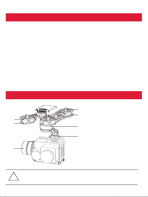
Gimbal Description
[1]
-2 -
[2]
[1] Gimbal fixed copper cylinder
[2] Damping balls
[5]
[3] Upper damping board
[4] Lower damping board
[6]
[5] YAW axis motor
[6] Roll axis motor
[7] Pitch axis motor
[3]
[4]
[7]
Please make sure that the motor is not stopped by any object during
the rotation, if the gimbal is blocked during rotation, please remove
!
the obstruction immediately.
Page 4
Gimal Dimenstion
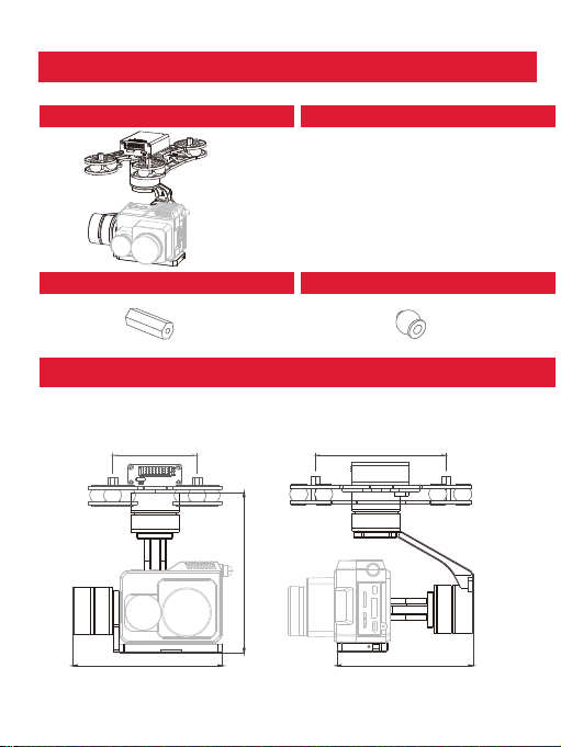
Gimbal*1
Copper cylinders*4 Damping balls*12
Screw pack*1
M3*5mm button head
Hexagon screw*4
Installing
84
133 .3
124 .3
-3-
106
113. 3
Uint: mm
Page 5
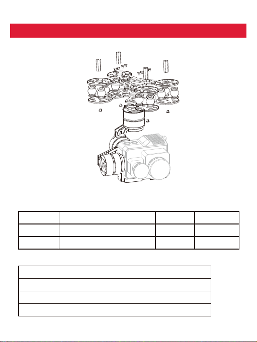
Installing
Mechanics@Electronic Characteristics
Input voltage
Dynamic current
Size
Working Characteristics
Pitch angle range of action: ±90°
Roll angle range of action: ±85°
Yaw/Pan: Yaw angle range of action : ±150°
Vibration angle: Pitch/Roll: ±0.02°, Yaw:±0.03°
3S~ 4S
450mA@12V
L105.3 *W 113.3*H133.3mm
-4 -
Idle current
Working
environment temp
Weight
330mA@12V
-10°℃~+50°℃
400g
Page 6
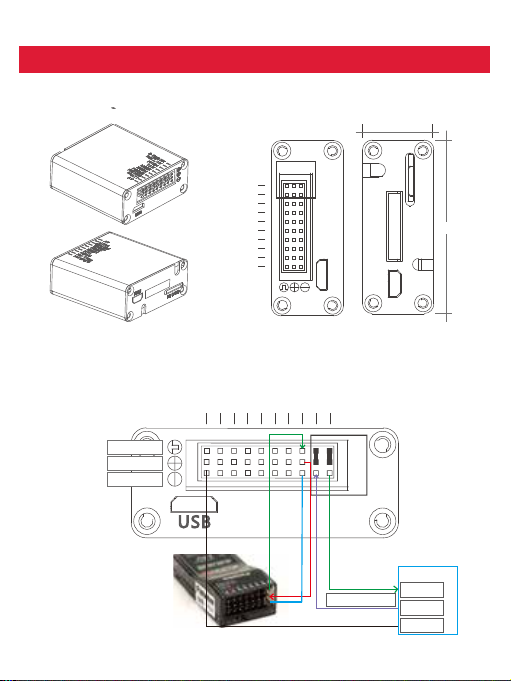
Connection of Control Box and Wiring Instruction
Uint:mm
19
.
S.b us/R x
Rol l/Tx
Foc us
.
Pic /Rec
Pit ch
Yaw
Mod e
Zoo m
Mul ti
1 2 3
SD C AR D
Av
US B
HD MI
45
PW M 1——Zoom
PW M2——Focus
PW M3——Pic/R ec
PW M in
5V output
GND
Pic/ Rec
Focu s
Zoom
Mult i
Av
S.bu s /Rx
Roll /Tx
Mode
Pitc h
Yaw
1 2 3
SB
U
USER BO AR D
TT L 96 00/8/1/N
RX
TX
GND
-5 -
Page 7
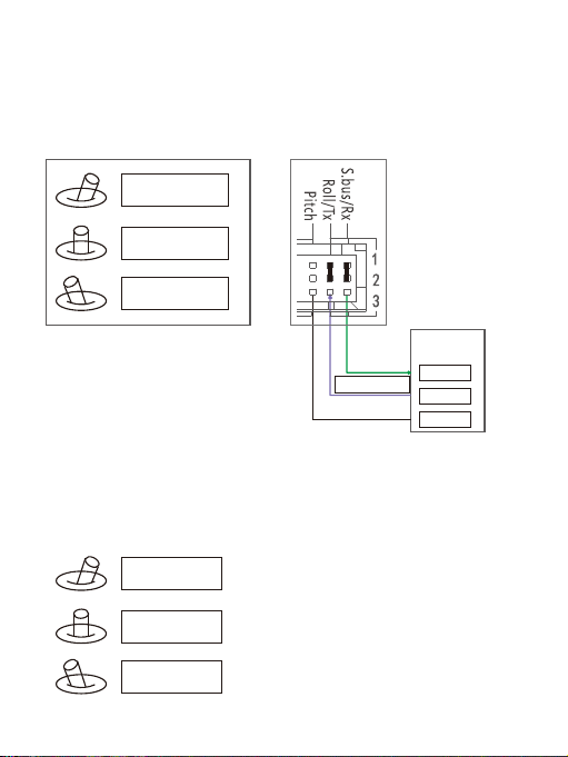
S.bus/Rx: connect to Rx2 for track function.
Roll/ Tx: connect to Tx2 for track function.
Pitch: PWM in, pitch control
1. Pitch up
2. Pitch stop
Pitch down
3.
Yaw:P W M i n, Yaw c on t ro l
1. Yaw right
2. Yaw stop
3. Yaw left
-6 -
co nt act o ur t ech ni cal
su p p or t f or d et a il
d oc .
TTL 1 15200 /8/1/ N
We h ave p rot oc ol f or
co n tr o l t he gi m ba l
an d c am era , pl eas e
USER BOARD /
GPS module
RX
TX
GND
Page 8
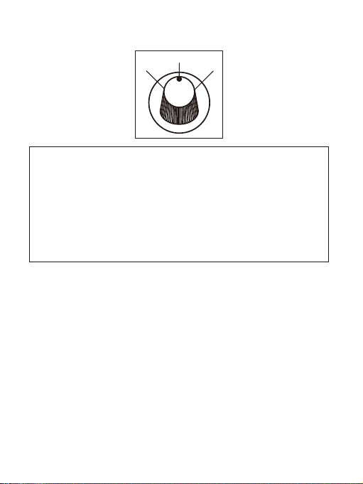
Mode: Change the speed / home position
2
1
Position 1: Lowest speed for pitch and yaw.
Position 2: Middle speed for pitch and yaw.
Position 3: Highest speed for pitch and yaw.
The speed is continuously quickly from 1 to 3.
One click: Home position.
Two click: Yaw not followed by frame.
Three click: Yaw followed by frame.
3
-7 -
 Loading...