

Page 4
Amplified Digital Indoor TV Antenna
PD
2011-9007-03
INSTRUCTIONS
Product features
Compact stylish indoor TV antenna suitable for reception of Freeview* digital terrestrial
signals in areas of adequate signal strength.
n High performance reception of analogue TV.
n Suitable for all UK TV transmissions, horizontal or vertical polarisation.
n Free-standing, or can be wall-mounted or used in a roof space (loft).
n Built-in high-gain mains-powered amplifier; no batteries required.
Use as a room antenna
Where use of a full-size outdoor or loft-mounted antenna is not desirable or practicable,
the prvANT1DAU can deliver good digital and analogue TV reception in areas of adequate
signal strength. This product will out-perform many other types of indoor aerial.
Indoor use is illustrated in Figs. 1 4. As usual with room antennas you will need to
experiment with the position of the product for best results. Most digital receivers and
adapters have a signal strength and quality display function (consult the handbook for
your equipment) and this should be used when positioning the antenna for best digital
reception. Always position for the best signal quality. Positions near to a window are
frequently best, especially if the window is facing toward the transmitter location.
Whether the horizontal or the vertical position is required depends on the polarisation of
your local transmitter. If this is not known, try both and see which gives the better results.
(See also Reception Advice Services on page 4.)
Performance data given are typical unless otherwise stated. View+ reserves the right to change product designs
and specifications without prior notice.
prvANT1DAU
2-Year Guarantee
This guarantee covers failure of your View+ product resulting from manufacturing defect within
a period of 2 years from the date of supply to the end-user. This guarantee does not cover
damage to the product caused by abuse, tampering, defective installation or natural causes
such as lightning discharge. Repair or attempted repair, other than by the manufacturer, will
render this guarantee void. This guarantee does not affect a consumers statutory rights.
Page 1
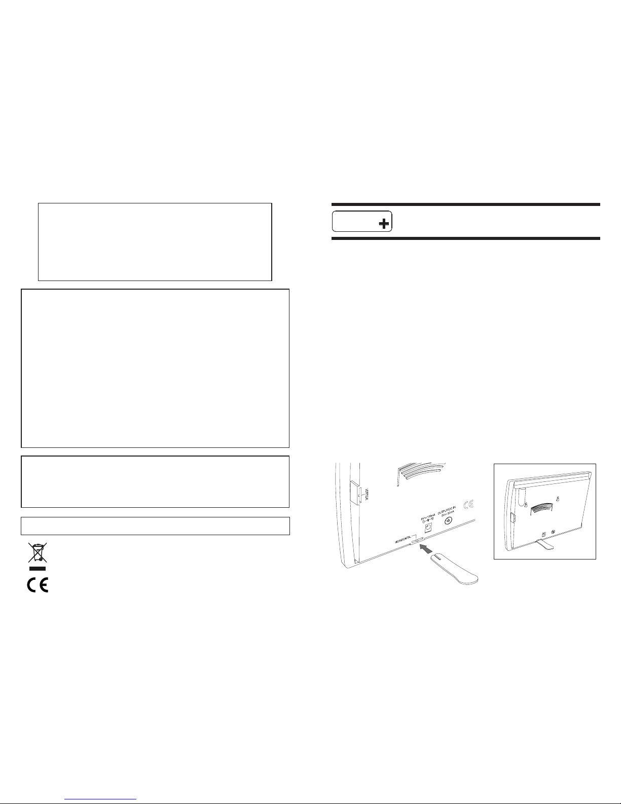
Fig. 1 - Indoor deployment for horizontal polarisation (most main transmitters).
9LHZ
* Freeview is a registered trade mark of the British Broadcasting Corporation.
Safety Instructions
OVERHEATING
The recommended ventilation clearances and other precautions given in the relevant section of
this instruction leaflet should be observed to prevent overheating. No unit should be fixed where
it is likely to become smothered by soft furnishing fabrics such as curtains, or by thermal insulation
material in a roof space or building void. Mains powered equipment should not be left resting on
a carpet.
WATER AND FIRE RISKS
The appliance is not waterproof. It is intended for indoor use only and must not be fixed where it
could be exposed to dripping or splashing water. Objects containing liquids should not be placed
on or near the appliance. To prevent risk of fire, no object with a naked flame should be placed
on or near the appliance, or its associated wiring.
MAINS POWER SUPPLY UNITS
The power unit(s) supplied as part of this appliance are suitable only for use with 13 A sockets to
BS 1363. Consult a qualified electrician if the socket outlets in the location where the appliance
is to be installed are of a different type.
FIXED WIRING
Any fixed wiring installed to supply power to this appliance should comply with BS 7671 (IEE
wiring regulations, 16th Edition). The appliance power units are of Class 2 construction and do
not require a protective earth connection. This does not obviate the need to provide a circuit
protective (earth) conductor in the supply wiring, as required by BS 7671.
(Information subject to change)
BBC Reception Advice 08700 100123
e-mail: reception@bbc.co.uk
web: http://www.bbc.co.uk/reception
Ofcom 0845 456 3000
e-mail: broadcast.technical@ofcom.org.uk
web: http:// www.ofcom.org.uk/static/reception_advice/index.asp
Reception Advice Services
Help Desk 08707 948494
www.viewplushelp.co.uk
+
9LHZ
Page 3Page 2
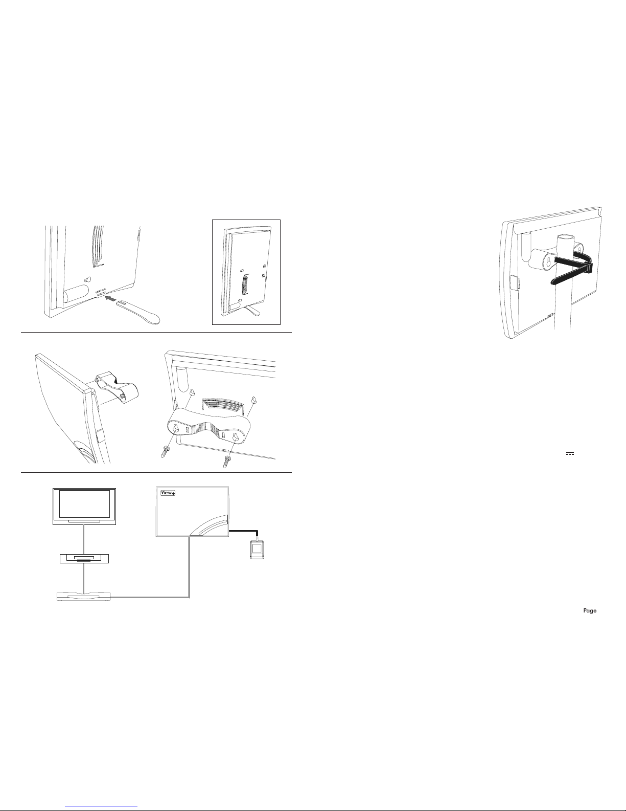
Fig. 2 - Indoor deployment for vertical polarisation (most smaller relay transmitters).
Fig. 3 - Wall mounted using the moulded bracket.
Fig. 4 - Connection diagram.
Freeview tuner
OUTPUT
VCR (optional)
ANT IN
ANT IN
ANT IN
RF OUT
RF OUT
power unit
DC power in
flylead (supplied)
Use in a loft space
For better results mount the antenna in a roof space
or similar high sheltered location Fig. 5. The
antenna should be mounted as high as possible and
away from metalwork such as water pipes or tanks
(cisterns), or structural steelwork. It should also be
kept as far as possible from mains wiring, although
a mains power point will be needed in reach of the
power supply lead (unless the alternative methods
of powering, described below, are employed). The
front face of the antenna should face toward the
transmitter and the polarisation must be correct.
Experiment with the mounting position before
deciding on the exact fixing position.
The support pole or mast (not supplied) can be any
suitable insulating material such as a length of
wooden dowel or plastic waste pipe. Alternatively,
the antenna can be fixed directly to a timber surface
using screws and the keyhole slots. Note that for
vertical polarisation the pole will need to be mounted horizontally.
To connect the loft-mounted antenna to your receiver you will need a length of coaxial
cable and two coaxial plugs (not supplied). The use of high-quality CAI benchmarked
cable is recommended. This may be wired via a screened wall outlet plate if desired, for a
professional-looking installation. Because of the high gain of the amplifier in the antenna,
signal loss on a long length of coaxial cable will not significantly affect the quality of the
signal delivered to the receiver.
*
Few Freeview receivers on the UK market have this capability at present, although the number
supporting it may increase in the future.
Fig. 5 - Loft mounting
Note: this diagram does
not show SCART cables.
Power supply unit
The power unit supplied is for use with standard UK (BS 1363) mains socket-outlets only.
Before connecting this equipment to the mains supply, refer to the safety instructions on
page 4.
To install, connect the lead from the power unit into the socket marked 6V 100 mA
on the back of the antenna, then plug the power unit into a suitably located mains socket
outlet and switch on.
Clearance of at least 30 mm should be allowed around the power unit for ventilation.
Do not install the power unit where it may become smothered with curtains or
other soft furnishing fabrics. When installing the power unit in a roof space ensure
that it will not come into contact with thermal insulation material.
Disconnect the power unit from the mains whenever the antenna is to remain unused for
long periods of time.
Alternative power supply
As an alternative to use of the power unit supplied, the antenna will also accept 5 6 V DC
power via the coaxial output socket. This allows it to be used with certain digital TV receivers*
which have an option to provide 5 V DC power at the antenna socket. If this method of
powering is used, the power unit supplied is not required. Consult the handbook for the
digital receiver for instructions on how to turn the antenna socket powering on.
NB Do not attempt to power this antenna using a standard 12 V masthead amplifier
power unit as this will damage the built-in amplifier.
 Loading...