

Viewpia LC-23IU21, LC-27IU31, LC-30IU21, LC-32IU11, LC-26IU11 User Manual
...
EUT Type: 42” LCD TV/Monitor
FCC ID: R7DLCD-42IU11
Test Report No.: GETEC-E3-05-048
FCC Class B Certification
APPENDIX H
: USER’S MANUAL

Please read this manual carefully before operating your set.
Retain it for future reference.
See the label attached on the back cover and quote this information to your dealer when you require service.
LC-23IU21 / LC-26IU11 / LC-27IU11 /
LC-27IU21 / LC-27IU31 / LC-30IU21 /
LC-32IU11 / LC-32IU21 / LC-32IU31 /
LC-37IU11 / LC-37IU21 / LC-42IU11
Colour Television
Colour Television
Owner’s Manual
P/NO : MAN05GDP018

WARNING:
TO PREVENT FIRE OR SHOCK HAZARDS, DO NOT EXPOSE
THIS PRODUCT TO RAIN OR MOISTURE.
NOTE TO CABLE/TV INSTALLER:
This reminder is provided to call the CATV system installer’s
attention to Article 820-40 of the National Electric Code
(U.S.A.). The code provides guidelines for proper grounding
and, in particular, specifies that the cable ground shall be connected to the grounding system of the building, as close to the
point of the cable entry as practical.
REGULATORY INFORMATION
This equipment has been tested and found to comply with the
limits for a Class B digital device, pursuant to Part 15 of the
FCC Rules. These limits are designed to provide protection
against harmful interference in a residential installation. This
equipment generates, uses and can radiate radio frequency
energy and, if not installed and used in accordance with the
instructions, may cause harmful interference to radio communications. However, there is no guarantee that interference will
not occur in a particular installation. If this equipment does
cause harmful interference to radio or television reception,
which can be determined by turning the equipment off and on,
the user is encouraged to try to correct the interference by one
or more of the following measures:
- Reorient or relocate the receiving antenna.
- Increase the separation between the equipment and receiver.
- Connect the equipment into an outlet on a circuit different from
that to which the receiver is connected.
- Consult the dealer or an experienced radio/TV technician for
help.
Any changes or modifications not expressly approved by the
party responsible for compliance could void the user’s authority to operate the equipment.
Warning
2
CAUTION
RISK OF ELECTRIC SHOCK
DO NOT OPEN
WARNING:
TO REDUCE THE RISK OF ELECTRIC SHOCK DO NOT REMOVE COVER (OR BACK). NO USER SERVICEABLE PARTS INSIDE. REFER TO QUALIFIED SERVICE PERSONNEL.
The lightning flash with arrowhead symbol, within an equilateral triangle, is intended to alert the user to
the presence of uninsulated “dangerous voltage” within the product’s enclosure that may be of sufficient
magnitude to constitute a risk of electric shock to persons.
The exclamation point within an equilateral triangle is intended to alert the user to the presence of important operating and maintenance (servicing) instructions in the literature accompanying the appliance.

1. Read these instructions
All the safety and operating instructions should be read before the product is operated.
2. Follow all instructions
All operating and use instructions should be followed.
3. Keep these Instructions
The safety and operating instructions should be retained for future reference.
4. Heed all warnings
All warnings on the product and in the operating instructions should be
adhered to.
5. Cleaning
Unplug this product from the wall outlet before cleaning. Do not use liquid
cleaners or aerosol cleaners. Use a damp cloth for cleaning. Clean only
with dry cloth.
6. Water and Moisture
Do not use this product near water, for example, near a bath tub, wash
bowl, kitchen sink, or laundry tub, in a wet basement, or near a swimming
pool. Do not use this apparatus near water.
7. Accessories Carts and Stands
Do not place this product on a slippery or tilted surface, or on an unstable
cart, stand, tripod, bracket, or table. The product may slide or fall, causing serious injury to a child or adult, and serious damage to the product.
Use only with a cart, stand, tripod, bracket, or table recommended by the
manufacturer, or sold with the product. Any mounting of the product
should follow the manufacturer’s instructions, and should use a mounting
accessory recommended by the manufacturer. Only use attachments/
accessories specified by the manufacturer. Use only with the cart, stand,
tripod, bracket, or table specified by the manufacturer, or sold with the
apparatus. When a cart is used, use caution when moving the cart/apparatus combination to avoid injury from tip-over.
8. Transporting Product
A product and cart combination should be moved with care. Quick stops,
excessive force, and uneven surfaces may cause the product and cart
combination to overturn.
9. Attachments
Do not use attachments not recommended by the product manufacturer
as they may cause hazards.
Safety Instructions
3
EN
Important safeguards for you and your new product
Your product has been manufactured and tested with your safety in mind. However, improper use can result in potential electrical shock or fire hazards. T o avoid defeating the safeguards that have been built into your new product, please read and observe the following safety points when installing
and using your new product, and save them for future reference.
Observing the simple precautions discussed in this booklet can help you get many years of enjoyment and safe operation that are built into your new
product.
When Information with regard to safety is required according to this standard. This information shall be given in a separate booklet or sheet, or be
located before any operating instructions in an instruction for installation for use and supplied with the apparatus. This information shall be in a language acceptable to the country where the apparatus is intended to be used.
The important safety instructions shall be entitled “Important Safety Instructions”. The following safety instructions shall be included where applicable,
and, when used, shall be verbatim as follows. Additional safety information may be included by adding statements after the end of the following safety instruction list. At the manufacturer’s option, a picture or drawing that illustrates the intent of a specific safety instruction may be placed immediately
adjacent to that safety instruction.
This product complies with all applicable U.S. Federal safety requirements, and those of the Canadian Standards Association.
PORTABLE CART WARNING
10. Ventilation
Slots and openings in the cabinet are provided for ventilation and to
ensure reliable operation of the product and to protect it from overheating, and these openings must not be blocked or covered. The openings
should never be blocked by placing the product on a bed, sofa, rug, or
other similar surface. This product should not be placed in a built-in installation such as a bookcase or rack unless proper ventilation is provided or
the manufacturer’s instructions have been adhered to. Do not block any
ventilation openings. Install in accordance with the manufacturer’s
instructions.
11. Power Sources
This product should be operated only from the type of power source indicated on the marking label. If you are not sure of the type of power supply to your home, consult your product dealer or local power company.
For products intended to operate from battery power, or other sources,
refer to the operating instructions.
12. Power-Cord Polarization
This product is equipped with a three-wire grounding type plug, a plug
having a third (grounding) pin. This plug will only fit into the groundingtype power outlet. This is a safety feature. If you are unable to insert the
plug into the outlet, contact your electrician to replace your obsolete outlet. Do not defeat the safety purpose of the grounding-type plug. Do not
defeat the safety purpose of the polarized or grounding-type plug. Apolarized plug has two blades with one wider than the other. A grounding type
plug has two blades and a third grounding prong. The wide blade or the
third prong are provided for your safety. If the provided plug does not fit
into your outlet, consult an electrician for replacement of the obsolete outlet. Protect the power cord from being walked on or pinched particularly
at plugs, convenience receptacles, and the point where they exit from the
apparatus.
13. Power-Cord Protection
Power-supply cords should be routed so that they are not likely to be
walked on or pinched by items placed upon or against them, paying particular attention to cords at plugs, convenience receptacles, and the point
where they exit from the product. Refer all servicing to qualified service
personnel. Servicing is required when the apparatus has been damaged
in any way, such as power-supply cord or plug is damaged. liquid has
been spilled or objects have fallen into the apparatus the apparatus has
been exposed to rain or moisture does not operate normally or has been
dropped.
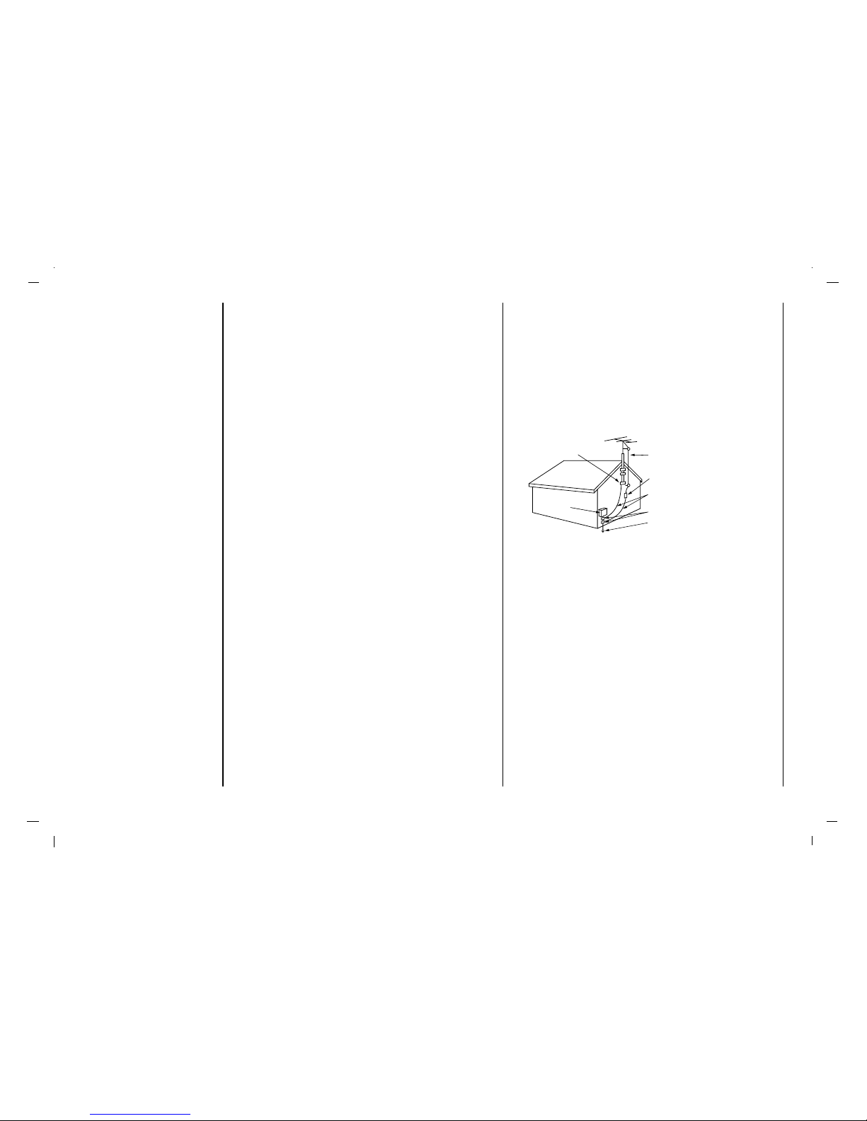
14. Outdoor Antenna Grounding
If an outside antenna or cable system is connected to the product, be
sure the antenna or cable system is grounded so as to provide some protection against voltage surges and built-up static charges. Article 810 of
the National Electrical Code (U.S.A.), ANSI/ NFPA 70 provides information with regard to proper grounding of the mast and supporting structure,
grounding of the lead-in wire to an antenna discharge unit, size of grounding conductors, location of antenna-discharge unit, connection to grounding electrodes, and requirements for the grounding electrode.
15. Lightning
For added protection for this product (receiver) during a lightning storm,
or when it is left unattended and unused for long periods of time, unplug
it from the wall outlet and disconnect the antenna or cable system. This
will prevent damage to the product due to lightning and power-line
surges. Unplug this apparatus during lightning storms or when unused for
long periods of time.
16. Power Lines
An outside antenna system should not be located in the vicinity of overhead power lines or other electric light or power circuits, or where it can
fall into such power lines or circuits. When installing an outside antenna
system, extreme care should be taken to keep from touching such power
lines or circuits as contact with them might be fatal.
17. Overloading
Do not overload wall outlets and extension cords as this can result in a
risk of fire or electric shock.
Safety Instructions
4
Antenna Lead in Wire
Antenna Discharge Unit
(NEC Section 810-20)
Grounding Conductor
(NEC Section 810-21)
Ground Clamps
Power Service Grounding
Electrode System (NEC
Art 250, Part H)
Ground Clamp
Electric Service
Equipment
Example of Grounding According to National
Electrical Code Instructions
NEC - National Electrical Code

Safety Instructions
5
EN
18. Object and Liquid Entry
Never push objects of any kind into this product through openings as they
may touch dangerous voltage points or short-out parts that could result in
a fire or electric shock. Never spill liquid of any kind on the product.
19. Servicing
Do not attempt to service this product yourself as opening or removing
covers may expose you to dangerous voltage or other hazards. Refer all
servicing to qualified service personnel.
20. Damage Requiring Service
Unplug this product from the wall outlet and refer servicing to qualified
service personnel under the following conditions:
a. If the power-supply cord or plug is damaged.
b. If liquid has been spilled, or objects have fallen into the product.
c. If the product has been exposed to rain or water.
d. If the product does not operate normally by following the operating
instructions. Adjust only those controls that are covered by the operating instructions as an improper adjustment of other controls may
result in damage and will often require extensive work by a qualified
technician to restore the product to its normal operation.
e. If the product has been dropped or the cabinet has been damaged.
f. If the product exhibits a distinct change in performance.
21. Service Instructions
These servicing instructions are for use by qualified service personnel
only. To reduce the risk of electric shock, do not perform any servicing
other than that contained in the operating instructions unless you are
qualified to do so.
22. Replacement Parts
When replacement parts are required, be sure the service technician has
used replacement parts specified by the manufacturer or have the same
characteristics as the original part. Unauthorized substitutions may result
in fire, electric shock, or other hazards.
23. Safety Check
Upon completion of any service or repairs to this product, ask the service
technician to perform safety checks to determine that the product is in
proper operating condition.
24. Wall or Ceiling Mounting
The product should be mounted to a wall or ceiling only as recommended by the manufacturer. The product may slide or fall, causing serious
injury to a child or adult, and serious damage to the product. Do not install
near any heat sources such as radiators, heat registers, stoves or other
apparatus (including amplifiers) that produce heat.
25. Heat
The product should be situated away from heat sources such as radiators, heat registers, stoves, or other products (including amplifiers) that
produce heat.
26. Wet Location Marking
Apparatus shall not be exposed to dripping or splashing and no objets
filled with liquids, such as vases, shall be placed on the apparatus.

Warnings 2
Safety Instructions 3-5
Contents 6
Location and function of controls 7-10
Remote control handset
Battery installation
Front panel
Back panel
Connection to External equipment 11-15
Basic operation 16
On and Off / Programme selection
Volume adjustment
On screen language selection (option)
On screen menus 17
Menu selection
Setting up TV stations 18-20
Memorizing the Channels with Auto
Add/Delete Channels with Manual
Fine Tuning Adjustment
Favorite Channels Setup
Picture Menu 21-23
CSM (Colour Status Memory)
PSM (Picture Status Memory)
Manual Picture Control
Picture Format
Sound Menu 24-26
SSM (Sound Status Memory)
Balance
AVL(Auto Volume Leveler)
Stereo/SAP Broadcasts Setup
Time Menu 27-29
Clock
On/Off Time
Auto sleep / Sleep timer
Setup Menu 30-31
Child lock
Caption
Caption/Text
Lock Menu (option) 32-34
Lock Menu options
Lock Menu Setup
RGB-PC Menu 35
PC Setup
PIP (Picture-In-Picture) Feature 36-37
Displayable Monitor Specification 38
Troubleshooting Check list 39
Contents
6
7
EN
Location and function of controls
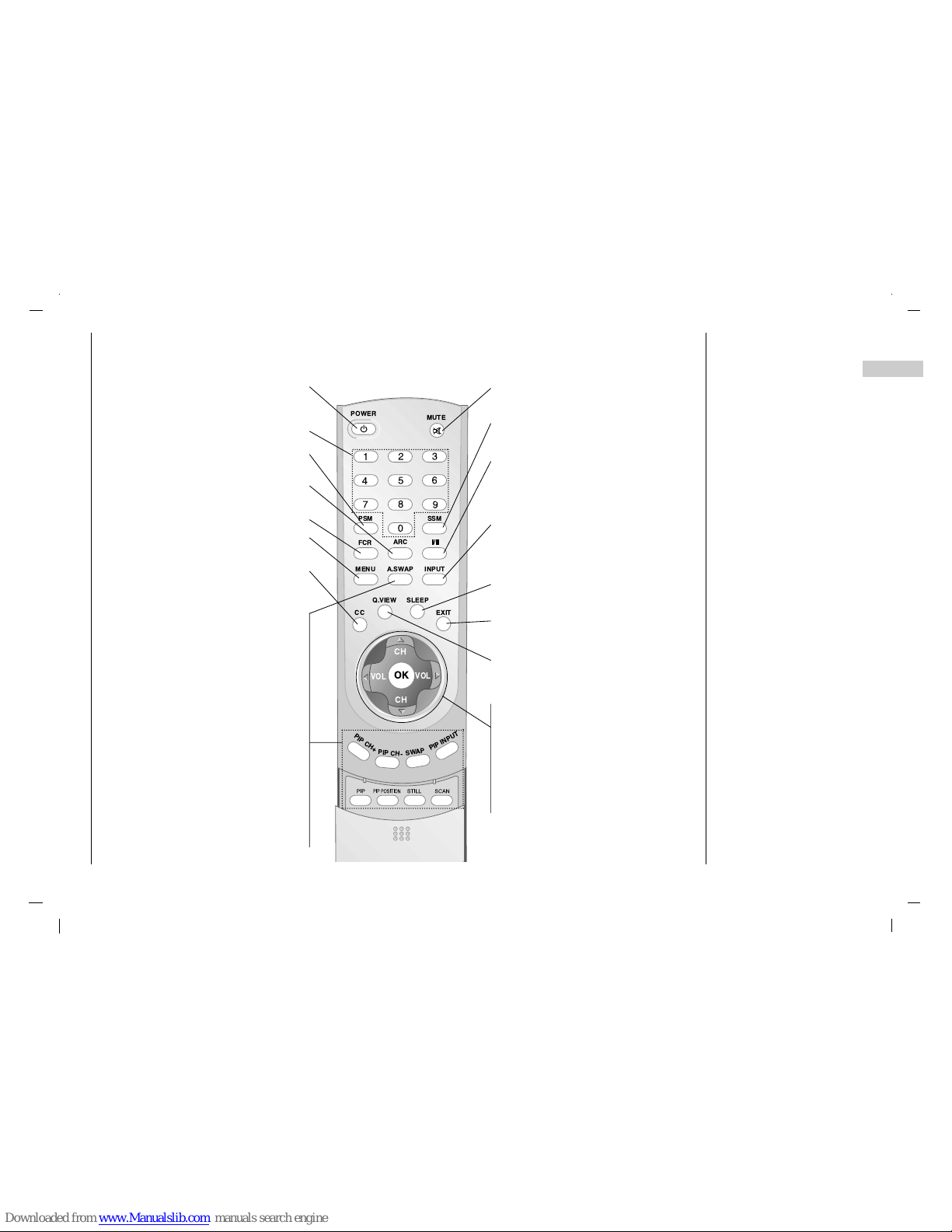
Remote control handset
- All the functions can be controlled with the remote control handset.
- Some functions can also be adjusted with the buttons on the front panel of the set.
- Before you use the remote control handset, please install the batteries.
POWER
switches the set On from standby or Off to
standby.
NUMBER BUTTONS
PSM (Picture Status Memory)
recalls your preferred picture setting.
ARC
select your desired picture format.
FCR (Favorite Channels Setup)
MENU
selects a menu.
CC
Select a closed caption : Off, EZ Mute, and
On.
PIP
Switches the sub picture on or off.
A.SWAP
PIP mode - main and sub picture audio
select.
PIP PR +/-
Selects a program for the sub picture.
SWAP
Alternates between main and sub picture.
PIP INPUT
Selects the input mode for the sub picture.
PIP POSITION
relocates the sub picture in clockwise direc-
tion.
STILL
freezes motion of the sub picture.
SCAN
switches on the programme scan mode
through 4/16 sub pictures.
MUTE
switches the sound on or off.
SSM (Sound Status Memory)
recalls your preferred sound setting.
I/II
selects the language during dual language
broadcast.
selects the sound output (option).
INPUT SELECT
Select TV, AV1, AV2, S-VIDEO, COMPONENT, PC-RGB, DVI mode.
switches the set on from standby.
SLEEP
sets the sleep timer.
EXIT
exits from each mode.
Q.VIEW
returns to the previously viewed programme.
D/ E
(Programme Up/Down)
selects a programme or a menu item.
switches the set on from standby.
F / G (Volume Down/Up)
adjusts the volume.
adjusts menu settings.
OK
accepts your selection or displays the
current mode.
OK
PSM
FCR
MENU
CC
PIP CH+
PIP CH-
SWAP
PIP INPUT
CH
VOL
VOL
CH
Q.VIEW
EXIT
SLEEP
INPUTA.SWAP
ARC
POWER
MUTE
SSM
8
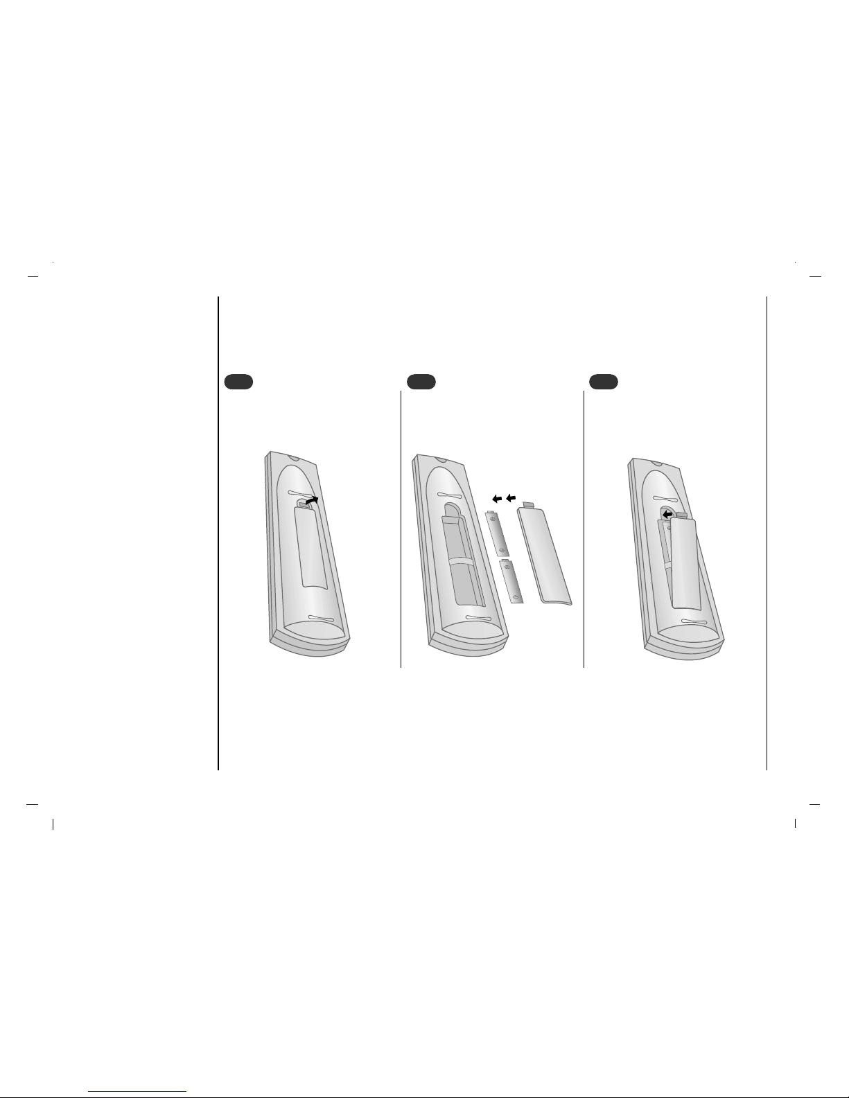
- Your remote control handset is powered by two AAA type batteries.
To insert batteries, turn the remote
control handset over and remove the
battery cover.
1
1
Put the two batteries into the compartment observing battery polarity.
2
2
Replace the cover.
To avoid damage from possible battery leakage, remove the batteries if
you do not plan to use the remote control handset for an extended period
time. Do not use batteries of differing
age or type. Always discard of batteries safely.
3
3
Location and function of controls
Battery installation
8
9
EN
Location and function of controls
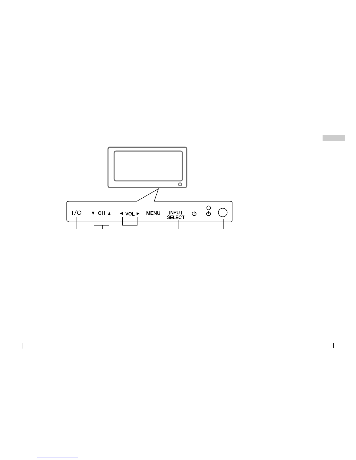
Front panel
1. MAIN POWER (I / yy)
switches the set On or Off.
2.
D / E
(Channel Up/Down)
selects a programme or a menu item.
switches the set On from standby.
3. F / G (Volume Down/Up)
adjusts the volume.
adjusts menu settings.
4. MENU
selects a menu.
5. INPUT SELECT
Select TV, AV1, AV2, S-VIDEO, COMPONENT, PCRGB, DVI mode.
switches the set on from standby.
6. POWER (rr)
switches the set On from standby or On to standby.
7. POWER/STANDBY INDICATOR (rr)
illuminates red in standby mode.
illuminates green when the set is switched on.
8. REMOTE CONTROL SENSOR
- Shown is a simplified representation of the set.
- Here shown may be somewhat different from your set.
1
4 5 6 7 8
2 3
10
DVI INPUTDVI INPUT
S-VIDEOS-VIDEOOPTICALOPTICAL
AUDIO INPUTAUDIO INPUT
AUDIO INPUT
AUDIO
R L
COMPONENT INPUT
(480i/480p/720p/1080i)
Y PbP
r
ANTANT. IN
AC INPUTAC INPUT
RGB INPUTRGB INPUT
AV1
VIDEO
AUDIO
L
R
AV2
VIDEO
AUDIO
L
R
1 2 3 4 5 6 7
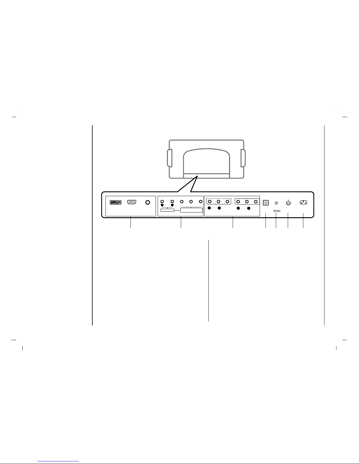
1. DVI INPUT / RGB INPUT / AUDIO INPUT SOCKETS
Connect the set output socket of the PERSONAL
COMPUTER to this socket.
2. AUDIO INPUT / COMPONENT INPUT (480i / 480p /
720p / 1080i) SOCKETS
3. AUDIO/VIDEO SOCKET
Connect the audio/video out sockets of the VCR to AV
sockets of the set
4. Digital Audio (OPTICAL)
Connect digital audio from various types of equipment.
Note : In standby mode, these ports will not work.
5. Antenna INPUT
6. S-VIDEO INPUT
connect video out from an S-VIDEO VCR to the SVIDEO input.
7. POWER CORD SOCKET
This set operates on an AC power. The voltage is indicated on the Specifications page. Never attempt to
operate the set on DC power.
Location and function of controls
Back panel
11
EN
Connection to External equipment
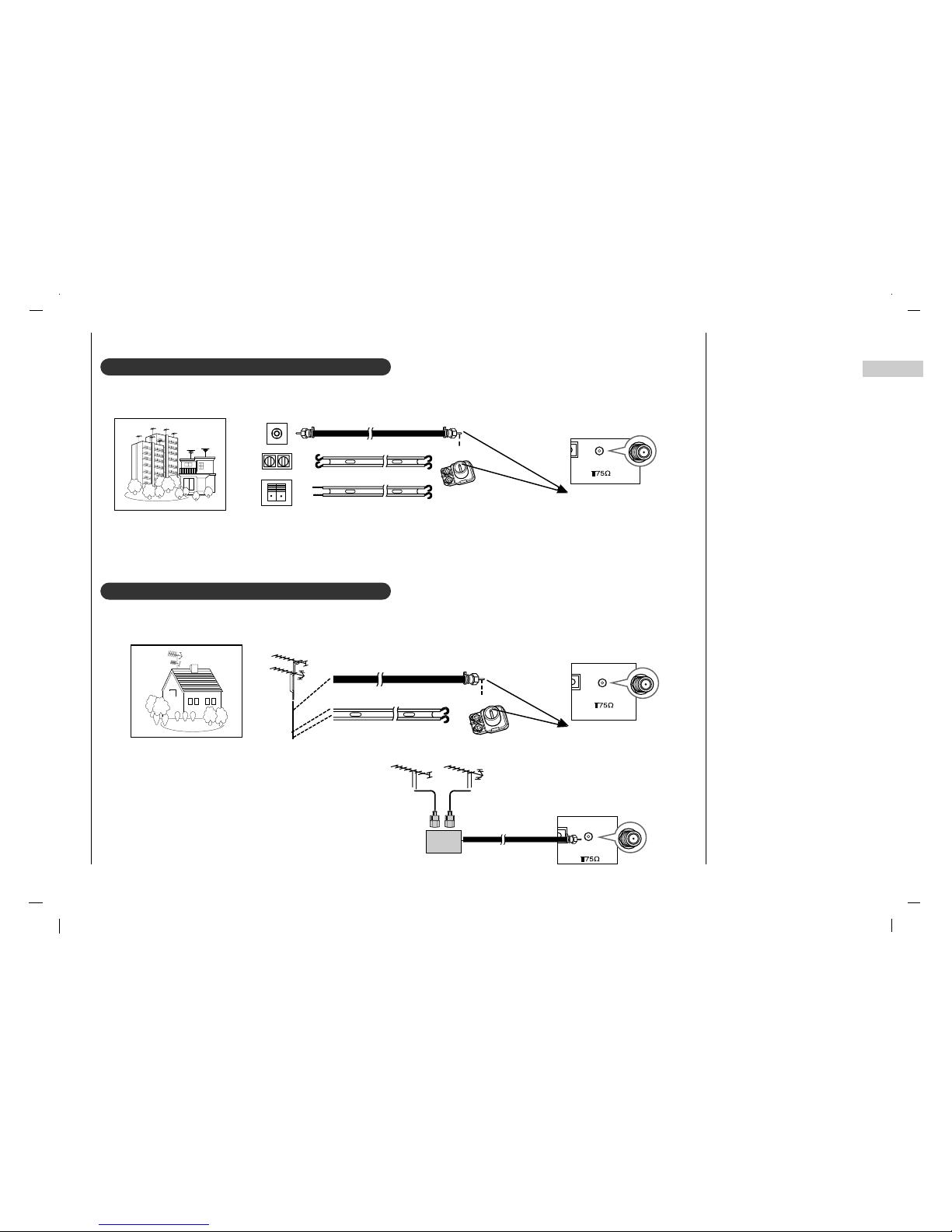
Connecting to an Inside Antenna Setup
Connecting to an Outdoor Antenna Setup
- If you have a 75Ω round cable, insert the bronze wire and then tighten the connection nut. If you have a 300Ω flat wire, connect the twisted wire to the antenna converter and then connect the converter to the antenna jack on the TV.
- If using 75Ω round cable, do not bend the bronze wire. It may cause poor picture quality.
Wall Connection Jack
Apartment Buildings
Antenna Jack
Bronze Wire
Turn clockwise to tighten.
Antenna
Converter
300Ω Flat Wire
75Ω Round Cable
S-VIDES-VIDEOICALOPTICAL
ANT. IN
AC INPUT
Antenna Jack
S-VIS-VIDEOTICALOPTICAL
ANT. IN
AC INPUT
S-
VS-VIDEOT
ICAL
ANT. IN
AC INPUT
UHF
Antenna
VHF Antenna
- In poor signal areas, to get better picture quality,
install a signal amplifier to the antenna as shown to
the right.
- If signal needs to be split for two TVs, use an
antenna signal splitter for connection.
Signal
Amplifier
UHF
VHF
Single Family Home
Bronze Wire
Turn clockwise to tighten.
Antenna Converter
300Ω Flat Wire
75Ω Round Cable
- This type of antenna is commonly used in single family dwellings.
- Typical wall antenna jack used in apartment buildings, connect the antenna cable as shown below.
(Use the correct type of antenna cable for the type of wall antenna jack.)
12
Connection to External equipment
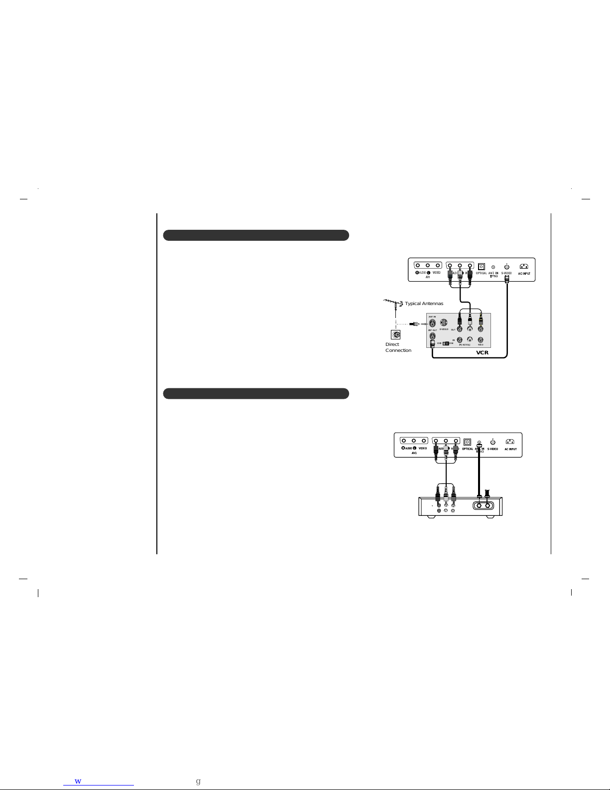
VCR Setup
- In Video mode, TV automatically reverts to TV mode if the CH
D / E
button or number buttons are pressed.
Connection 1
Set VCR switch to 3 or 4 and then tune TV to the same channel number.
Connection 2
1. Connect the audio/video output jacks on VCR to the corresponding
input jacks on the TV. When connecting the TV to a VCR, match the
jack colors (Video = yellow, Audio Left = white, and Audio Right =
red).
2. Insert a video tape into the VCR and press PLAYon the VCR. (Refer
to the VCR owner’s manual.)
3. Use the INPUT SELECT button on the remote control to select AV1
or AV2. (If connected to S-VIDEO on side panel, select the S-Video
external input source.)
Cable TV Setup
- After subscribing to a local cable TV service and installing a converter,
you can watch cable TV programming.
- For further cable TV information, contact a local cable service provider.
Connection 1
1. Select 3 or 4 with channel switch on cable box.
2. Tune the TV channel to the same selected output channel of cable box.
3. Select channels at the cable box or with the cable box remote control.
Connection 2
1. Connect the audio/video output jacks on Cable Box to the corre-
sponding input jacks on the TV. When connecting the TV to Cable
Box, match the jack colors
(Video = yellow, Audio Left = white, and Audio Right = red).
2. Use the INPUT SELECT button on the remote control to select AV1
or AV2.
3. Select channels with the cable box remote control.
S-VIDEOOPTICAL
ANT.IN. IN
AC INPUTAC INPUT
AV1
VIDEO
AUDIO
L
R
AV2
VIDEO
AUDIO
L
R
OUT
IN
CH3 CH4
S-VIDEO
ANTIN
ANTOUT
(R) (L)
AUDIO VIDEO
Typical Antennas
VCR
Direct
Connection
S-VIDEOOPTICALOPTICAL
ANT. IN
AC INPUT
AV1
VIDEO
AUDIOAUDIO
L
R
AV2
VIDEO
AUDIOAUDIO
L
R
TV
VCR
(R) AUDIO (L) VIDEO
RF Cable
Cable Box
 Loading...