

Viewpia LC-32IEE4 Owner's Manual

Colour Television
Colour Television
Owner’s Manual
Please read this manual carefully before operating your set.
Retain it for future reference.
See the label attached on the back cover and quote this information to
your dealer when you require service.

Installation 3
Remote control handset 4-5
Controls 4
Battery installation 5
Controls of
Front panel 6
Connections of
Back panel 7
Connection to
External equipment 8-12
Basic operation
On and Off 13
Programme selection 13
Volume adjustment 13
On screen language selection 13
On screen menus
Menu selection 14
Setting up TV stations 15-19
Auto programme tuning 15
Manual programme tuning 16-17
Programme edit 18-19
Calling the programme table 19
Picture adjustment 20-22
CSM (Colour Status Memory) 20
PSM (Picture Status Memory) 21
Manual Picture Control 21
Picture Format 22
Sound adjustment 23-26
SSM (Sound Status Memory) 23
Balance 24
AVL(Auto Volume Leveler) 24
SRS TruSurround XT 25
TV Speaker 25
Stereo/Dual/NICAM reception 26
Time Menu 27-29
Clock 27
On/Off time 28
Auto sleep / Sleep timer 29
Setup Menu
Child Lock 30
Connection of PC
PC Setup 31
WXGA or VGA (Only PC-RGB mode) 31
PIP (Picture-In-Picture) Feature 32-34
Watching PIP 32
PIP Audio Output 33
Moving the PIP 33
Selecting a Input Signal Source for the PIP 33
Programme selection for sub picture 34
Programme scan 34
Teletext (option) 35-36
Displayable Monitor Specification 37
Troubleshooting
Check list 39
Contents
2
Power
This set operates on an AC mains supply, the voltage is as
indicated on the label on the back cover. Never apply DC
power to the set. In the event of thunderstorms or powercuts, please pull out the aerial and mains plugs.
Warning
To prevent fire or shock hazard, do not expose the set to
rain or moisture. Do not rub or strike the Active Matrix LCD
with anything hard as this may scratch, mar, or damage the
Active Matrix LCD permanently.
Service
Never remove the back cover of the set as this can expose
you to very high voltage and other hazards. If the set does
not operate properly, unplug it and call your dealer.
Aerial
Connect the aerial cable to the socket marked +75 Ω on
the back cover. For the best reception an outdoor aerial
should be used.
Location
Position your set so that no bright light or sunlight falls
directly onto the screen. Care should be taken not to
expose the set to any unnecessary vibration, moisture,
dust or heat. Also ensure that the set is placed in a position to allow a free flow of air. Do not cover the ventilation
openings on the back cover.
Cleaning
Unplug the set before cleaning the face of the LCD Screen.
Dust the set by wiping the screen and the cabinet with a
soft, clean cloth. If the screen requires additional cleaning,
use a clean, damp cloth. Do not use liquid cleaners or
aerosol cleaners.
Installation
3
EN
To preserve the Environment,
do not rubbish.
- All the functions can be controlled with the remote control handset.
- Some functions can also be adjusted with the buttons on the front panel of the set.
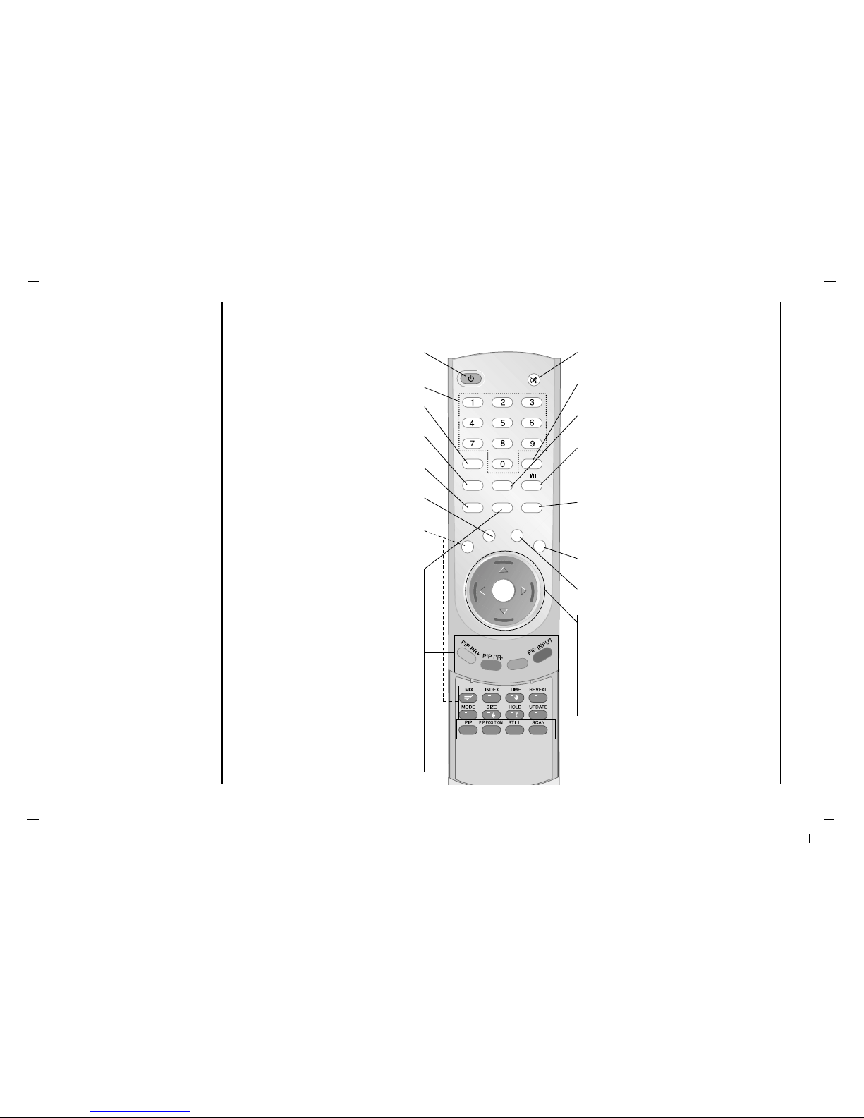
Remote control handset
Controls
Before you use the remote
control handset, please
install the batteries.
4
POWER
Select the set On or Off.
NUMBER BUTTONS
PSM (Picture Status Memory)
Recalls your preferred picture setting.
LIST
Displays the programme table.
MENU
Selects a menu.
Q.VIEW
Returns to the previously viewed programme.
TELETEXT BUTTONS (option)
These buttons are used for teletext.
For further details, see the ‘Teletext’ section.
PIP
Switches the sub picture On or Off.
A.SWAP
PIP mode - main and sub picture audio
select.
PIP PR +/-
Selects a programme for the sub picture.
PIP INPUT
Selects the input mode for the sub picture.
PIP POSITION
Relocates the sub picture in clockwise direc-
tion.
STILL
Freezes motion of the sub picture.
SCAN
Switches on the programme scan mode
through 9 sub pictures.
MUTE
Switches the sound On or Off.
SSM (Sound Status Memory)
Recalls your preferred sound setting.
ARC
Select your desired picture format.
I/II
Selects the language during dual language
broadcast.
Selects the sound output.
INPUT
Select TV, AV1, AV2, AV3, S-Video, Component,
PC-RGB, HDMI mode.
Switches the set on from standby.
EXIT
Exits from each mode.
SLEEP
Sets the sleep timer.
D/ E
(Programme Up/Down)
Selects a programme or a menu item.
Switches the set on from standby.
F / G (Volume Up/Down)
Adjusts the volume.
Adjusts menu settings.
OK
Accepts your selection or displays the
current mode.
- COLOURED BUTTONS
These buttons are used for teletext (only
TELETEXT models) or programme edit.
i
?
M
X
PSM
LIST
MENU
TEXT
Q.VIEW
EXIT
SLEEP
INPUTA.SWAP
ARC
POWER
MUTE
SSM
OK
EN
Remote control handset
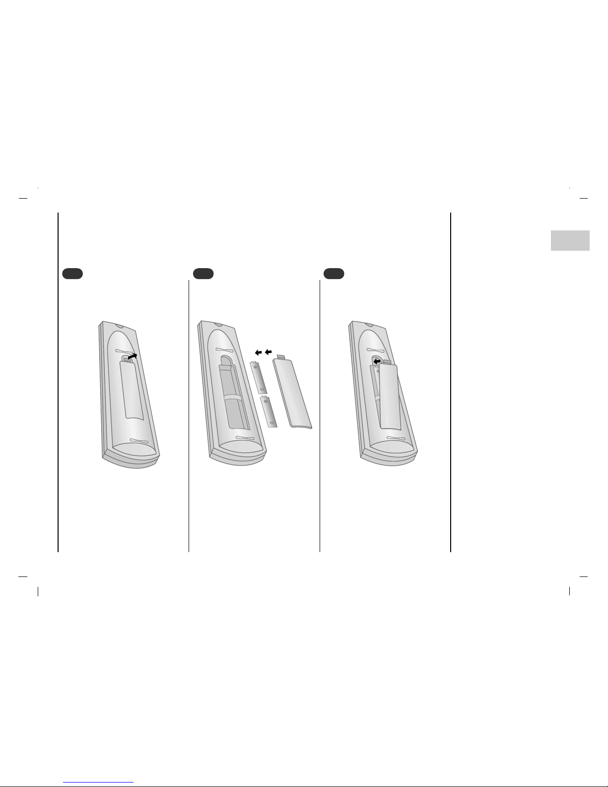
Battery installation
5
- Your remote control handset is powered by two AAA type batteries.
To insert batteries, turn the remote
control handset over and remove the
battery cover.
1
1
Put the two batteries into the compartment observing battery polarity.
2
2
Replace the cover.
To avoid damage from possible battery leakage, remove the batteries if
you do not plan to use the remote control handset for an extended period
time. Do not use batteries of differing
age or type. Always discard of batteries safely.
3
3
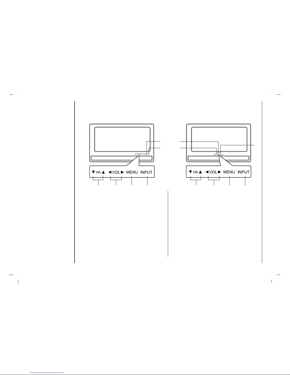
Controls of
Front panel
6
- Shown is a simplified representation of the set.
- Here shown may be somewhat different from your set.
1. POWER (rr)
Select the set On or Off.
2. INPUT
Selects TV, AV 1 , AV 2 , AV 3 , S-Video, Component,
PC-RGB, HDMI mode.
3. MENU
Selects a menu.
4. F / G (Volume Down/Up)
Adjusts the volume.
Adjusts menu settings.
5.
D / E
(Programme Up/Down)
Selects a programme or a menu item.
Switches the set On from standby.
6. REMOTE CONTROL SENSOR
7. POWER/STANDBY INDICATOR(rr)
Illuminates red in standby mode.
Illuminates green when the set is switched On.
3 2
6
1/7
5 4
3 2
5 4
7
6
1
Connections of
Back panel
7
EN
AC IN
Air
AUDIO IN
(RGB/DVI)
SERVICE
RGB IN
(PC/DTV)
DIGITAL AUDIO
(OPTICAL) OUT
HDMI(DVI)
YPb
Pr
COMPONENT IN
(R)
(L)
(R)
(L)
S-VIDEO IN
AV1
AV2
(R)
(L)
VIDEO
AV3 IN
1 2
3
4
6
7
5
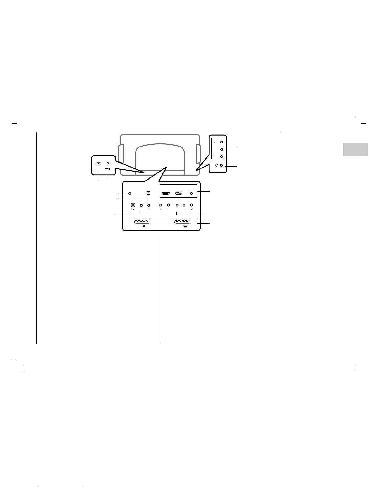
1. POWER CORD SOCKET
This set operates on an AC power. The voltage is indicated on the Specifications page. Never attempt to
operate the set on DC power.
2. AERIAL SOCKET
3. SERVICE ONLY SOCKET
4. DIGITAL AUDIO (OPTICAL) OUT
Connect digital audio from various types of equipment.
Note : In standby mode, these ports will not work.
5. HDMI(DVI) / RGB IN / AUDIO IN SOCKETS
Connect the set output socket of the PERSONAL
COMPUTER to this socket.
6. S-VIDEO IN
Connect video out from an S-Video VCR to the SVIDEO input.
7. COMPONENT IN (480i / 576i / 480p / 576p / 720p /
1080i) SOCKETS
8. EURO SCART SOCKET
Connect the euro scart socket of the VCR to these
sockets.
9. AUDIO/VIDEO IN SOCKET
Connect the audio/video out sockets of the VCR to AV
sockets of the set.
10. HEADPHONE SOCKET
Connect the headphone plug to this socket.
8
10
9
Connection to
External equipment
8
- You can connect additional equipment, such as VCRs, camcorders etc. to your set. However please check with your
manufacturers instruction books for specific information. Make sure all connections are made with both your set and
additional appliance unplugged from the mains to avoid damaging your equipment. Here shown may be somewhat different from your set.
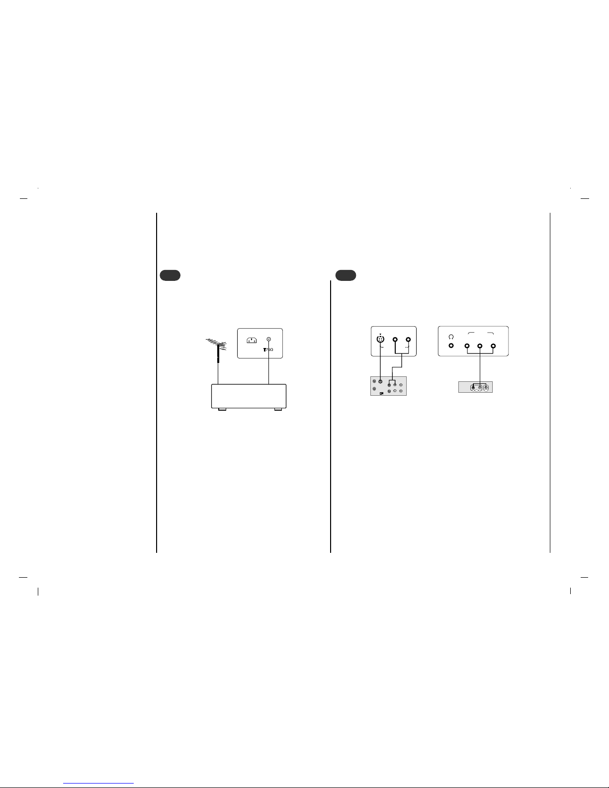
Connect the RF out socket of the VCR to the aerial
socket on the back of the set.
Connect the aerial cable to the RF aerial in socket
of the VCR.
Store the VCR channel on a desired programme
number using the ‘Manual programme tuning’ sec-
tion.
Select the programme number where the VCR
channel is stored.
Press the PLAY button on the VCR.
Connect to Aerial socket
- If you connect an S-VIDEO VCR to the S-VIDEO input, the picture quality is improved; compared to connecting a regular VCR
to the Video input.
- To avoid picture noise (interference), leave an adequate dis-
tance between the VCR and set.
Use the INPUT button on the remote control to select AV 1 , AV 2 ,
AV 3 or S-Video.
Insert a video tape into the VCR and press the PLAYbutton on the
VCR. (See VCR owner’s manual).
Watching VCR
VCR
AC IN
Air
S-VIDEO
OUT
IN
(R) AUDIO (L) VIDEO
(R)
(L)
S-VIDEO IN
(R)
(L)
VIDEO
AV3 IN
RL
AUDIO VIDEO
1
1
2
2
< Back panel of the set >
< Side panel of the set >
< Back panel of the set >
< Back panel of VCR >
Connection to
External equipment
9
EN
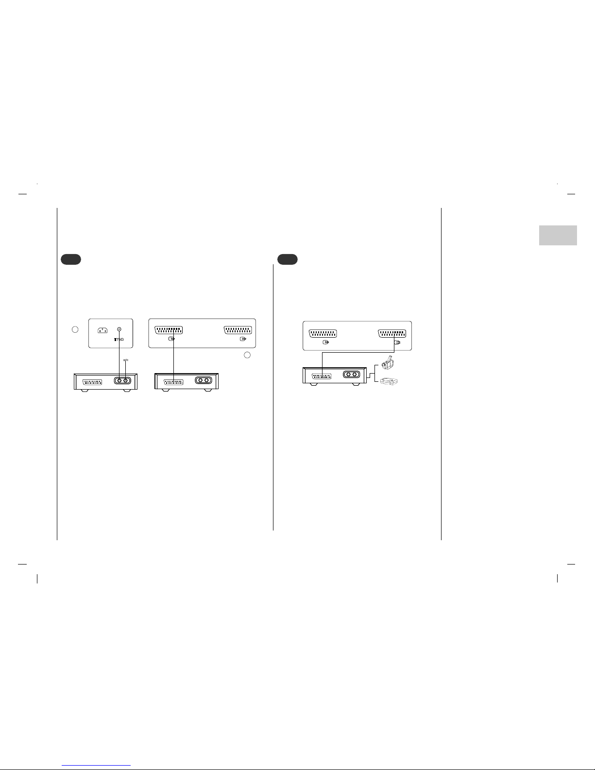
- After subscribing for a local cable TV station and installing a converter you can watch cable TV.
- For further information of cable TV, contact the local cable TV
station.
In using connection 1
Select programme number in programme switch of cable box.
Match the set programme with selected programme of cable box.
Select your desired programme with the remote control for cable
box.
In using connection 2
Use the INPUT button on the remote control and select AV 1 ,AV 2 ,
AV 3 or S-Video.
Tune to cable service provided channels using the cable box.
Cable
RF
AC IN
Air
Cable
RF
AV1
AV2
Watching Cable TV
3
3
When connecting the set to an external source,
match the colours of AUDIO/VIDEO input jacks on
the set with the output jacks on the audio/video
equipment:
Use the INPUT button on the remote control to
select AV 1 , AV 2 , AV 3 or S-Video.
Operate the corresponding external equipment.
See external equipment operating guide.
AV1
AV2
Cable
RF
Watching external AV source
4
4
For cable TV
< Cable Box >
< Back panel of the set >
< Back panel of the set >
Camcorder
Video game set
< Back panel of the exter-
nal equipment >
2
1
Connection to
External equipment
10
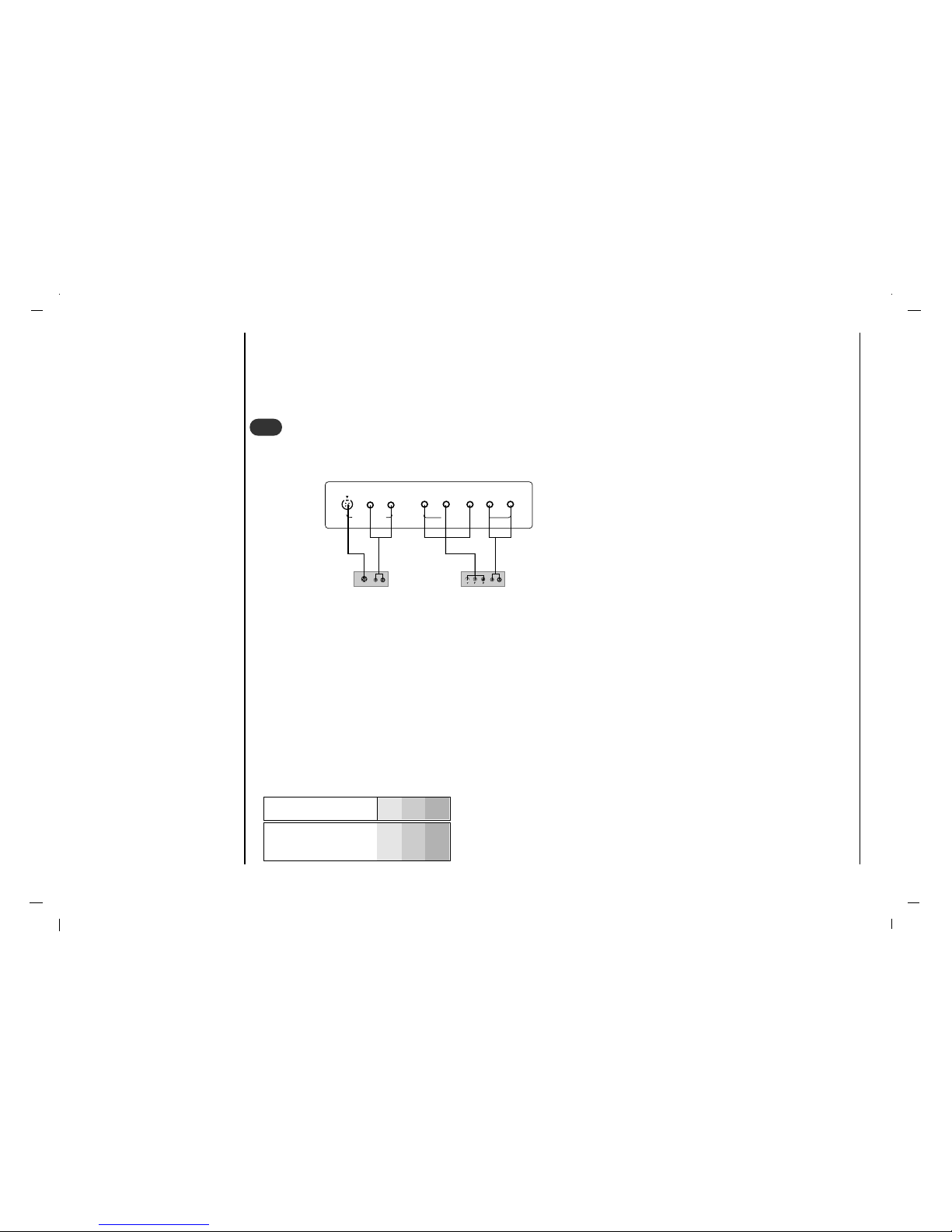
• COMPONENT Input ports
You can get better picture quality if you connect DVD player with COMPONENT input ports as below.
DVD input signal : 480i / 576i / 480p / 576p / 720p / 1080i
How to connect
Connect DVD video inputs to Y, Pb, Pr of COMPONENT (DVD INPUT) and audio inputs to Audio sockets of AUDIO
INPUT.
How to use
Turn on the DVD player, and insert a DVD.
Use INPUT button on the remote control to select Component. Refer to the DVD player's manual for operating instruc-
tions.
Watching DVD
B
R
(R) AUDIO (L)
(R) AUDIO (L)
S-VIDEO
YPb
Pr
COMPONENT IN
(R)
(L)
(R)
(L)
S-VIDEO IN
5
5
< Back panel of the set >
< Back panel of a DVD player >
or
COMPONENT
ports of the set
Y Pb
Pr
Video output ports
of DVD player
Y
Y
Y
Y
Pb
B-Y
Cb
PB
Pr
R-Y
Cr
P
R
Connection to
External equipment
11
EN
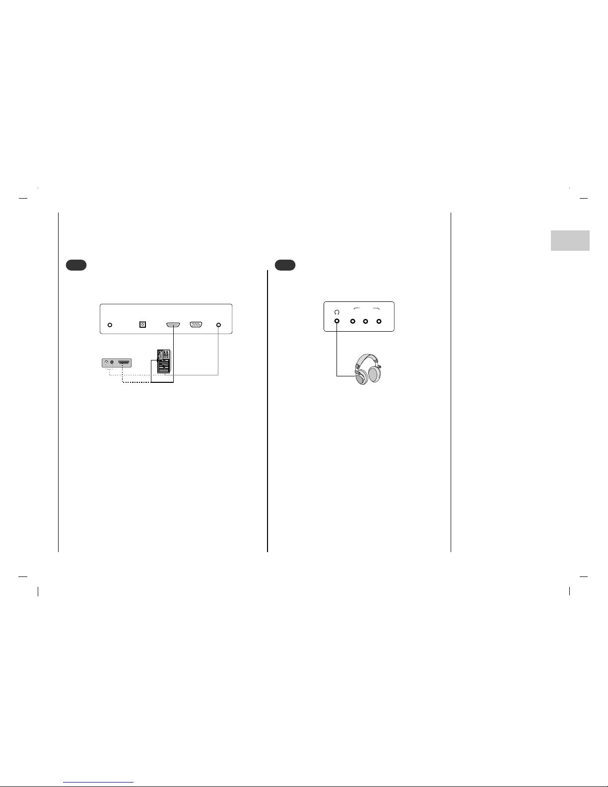
Connect the signal cable from the monitor output socket of the
PERSONAL COMPUTER to the HDMI socket of the set.
Connect the audio cable from the PC to the AUDIO IN sockets of the set.
Press the INPUT button to select HDMI.
Switch on the HDMI, and the HDMI screen appears on the
set.
HDMI-DTV input signal : 480p-60Hz, 576p-50Hz, 720p-
50Hz, 720p-60Hz, 1080i-50Hz, 1080i-60Hz.
HDMI Interface with HDCP Copy Protection enables all-digital
rendering of video without the losses.
This TV SET can receive the High-Definition Multimedia
Interface(HDMI) or Input of Digital Visual Interface(DVI).
Connecting HDMI (DTV)
HDMI OUTPUTHDMI OUTPUT
(R) (R) AUDIO (L)AUDIO (L)
AUDIO IN
(RGB/DVI)
SERVICE
RGB IN
(PC/DTV)
DIGITAL AUDIO
(OPTICAL) OUT
HDMI(DVI)
6
6
< Back panel of the set >
or
Insert the headphone plug to the headphone socket
of the set.
You can listen to the sound through the headphone.
To adjust the headphone volume, press the F / G
button.
Connecting Headphone
(R)
(L)
VIDEO
AV3 IN
7
7
< Side panel of the set >

Connection to
External equipment
12
Connect the signal cable from the monitor output socket
of the PERSONAL COMPUTER to the RGB IN socket of
the set.
Connect the audio cable from the PC to the AUDIO IN
sockets of the set.
Press the INPUT button to select PC-RGB.
Switch on the PC, and the PC screen appears on the set.
The set can be operated as the PC monitor.
RGB-DTV input signal : 480p-60Hz, 576p-50Hz, 720p-
50Hz, 720p-60Hz, 1080i-50Hz, 1080i-60Hz.
Connecting PC (DTV)
RGB OUTPUTRGB OUTPUT
(R) (R) AUDIO (L)AUDIO (L)
AUDIO IN
(RGB/DVI)
SERVICE
RGB IN
(PC/DTV)
DIGITAL AUDIO
(OPTICAL) OUT
HDMI(DVI)
7
7
- Send the set’s audio to external audio equipment (stereo
system) via the Digital Audio Output (Optical).
Caution : Do not look into the optical output port. Looking
at the laser beam may damage your vision.
How to connect
Connect one end of an optical cable to the TV Digital
Audio (Optical) Output port.
Connect the other end of the optical cable to the digital
audio (optical) input on the audio equipment.
Connecting Digital Audio
AUDIO IN
(RGB/DVI)
SERVICE
RGB IN
(PC/DTV)
DIGITAL AUDIO
(OPTICAL) OUT
HDMI(DVI)
8
8
< Back panel of the set >
< Back panel of the set >
or
 Loading...