

Page 1
Page 2
VT Camera Link series
Version
Date
Description
1.0
2016-03-04
First Release
Revision History
Page 2 of 77 VW40-161-001
Page 3

VT Camera Link series
Contents
1 Precautions ....................................................................................................................... 6
2 Warranty .......................................................................................................................... 8
3 Compliance & Certifications ............................................................................................ 8
3.1 FCC Compliance ......................................................................................................................... 8
3.2 CE : DoC ...................................................................................................................................... 8
3.3 KC ................................................................................................................................................ 8
4 Package Components ...................................................................................................... 9
5 Product Specifications ................................................................................................... 10
5.1 Overview .................................................................................................................................... 10
5.2 Specifications ............................................................................................................................. 11
5.3 Camera Block Diagram .............................................................................................................. 13
5.4 Spectral Response .................................................................................................................... 14
5.5 Mechanical Specification ........................................................................................................... 15
5.5.1 Camera Mounting and Heat Dissipation ..........................................................................................15
6 Connecting the Camera .................................................................................................. 16
6.1 Precaution to Center the Imaging Sensor .................................................................................. 16
6.2 Controlling the Camera .............................................................................................................. 16
7 Camera Interface ............................................................................................................. 17
7.1 General Description ................................................................................................................... 17
7.2 Camera Link Connector ............................................................................................................. 17
7.3 Power Input Receptacle ............................................................................................................. 21
7.4 Control I/O Receptacle .............................................................................................................. 22
7.5 Trigger / Direction Input Circuit .................................................................................................. 23
7.6 Strobe Output Circuit ................................................................................................................. 23
8 Acquisition Control ......................................................................................................... 24
8.1 Line Start Trigger ....................................................................................................................... 24
8.1.1 Trigger Mode ...................................................................................................................................24
8.1.2 Using an External/CC1 Trigger Signal .............................................................................................27
8.1.3 Rescaler Mode.................................................................................................................................28
8.2 Maximum Allowed Line Rate ..................................................................................................... 29
Page 3 of 77 VW40-161-001
Page 4

VT Camera Link series
9 Camera Features ............................................................................................................. 30
9.1 Operation Mode ......................................................................................................................... 30
9.2 TDI Stages ................................................................................................................................. 31
9.3 Direction ..................................................................................................................................... 33
9.4 Region of Interest ...................................................................................................................... 34
9.4.1 Setting the ROI ................................................................................................................................34
9.5 Binning ....................................................................................................................................... 36
9.6 Data Bit ...................................................................................................................................... 37
9.7 Gain and Black Level ................................................................................................................. 38
9.8 Dark Signal Non-uniformity Correction ...................................................................................... 39
9.8.1 Generating and Saving User DSNU Correction Values ..................................................................40
9.9 Photo Response Non-uniformity Correction .............................................................................. 42
9.9.1 Generating and Saving User PRNU Correction Values ..................................................................43
9.10 Reverse X ............................................................................................................................. 44
9.11 Camera Link Output .............................................................................................................. 45
9.12 Strobe Mode .......................................................................................................................... 46
9.13 Temperature Monitor ............................................................................................................. 47
9.14 Status LED ............................................................................................................................ 47
9.15 Test Image ............................................................................................................................. 48
9.16 Pre-emphasis ........................................................................................................................ 50
9.17 Field Upgrade ........................................................................................................................ 50
10 Camera Configuration .................................................................................................... 51
10.1 Setting Commands ................................................................................................................ 51
10.2 User Set Control .................................................................................................................... 53
10.2.1 Factory Default Setting Values ........................................................................................................54
10.3 Command List ....................................................................................................................... 55
11 Configurator GUI ............................................................................................................. 61
11.1 Camera Scan ........................................................................................................................ 61
11.2 Menu ..................................................................................................................................... 62
11.2.1 File ...................................................................................................................................................62
11.2.2 Start-Up ...........................................................................................................................................63
11.2.3 Tool ..................................................................................................................................................64
11.2.4 About ...............................................................................................................................................65
Page 4 of 77 VW40-161-001
Page 5

VT Camera Link series
11.3 Tab ........................................................................................................................................ 66
11.3.1 VIEW Tab .........................................................................................................................................66
11.3.2 MODE/EXP Tab ...............................................................................................................................67
11.3.3 VIDEO Tab .......................................................................................................................................68
12 Troubleshooting .............................................................................................................. 69
Appendix A Field Upgrade ................................................................................................. 70
A.1 MCU ........................................................................................................................................... 70
A.2 FPGA ......................................................................................................................................... 73
Appendix B Correction Control ......................................................................................... 74
B.1 Adjusting and Saving Additional DSNU Correction Value .......................................................... 75
B.2 Adjusting and Saving Additional PRNU Correction Value .......................................................... 76
Page 5 of 77 VW40-161-001
Page 6
VT Camera Link series
Do not drop, disassemble, repair or alter the device. Doing so may damage the camera
electronics and cause an electric shock.
Do not let children touch the device without supervision.
Stop using the device and contact the nearest dealer or manufacturer for technical
assistance if liquid such as water, drinks or chemicals gets into the device.
Do not touch the device with wet hands. Doing so may cause an electric shock.
Make sure that the temperature of the camera does not exceed the temperature range
specified in 5.2 Specifications. Otherwise the device may be damaged by extreme
temperatures.
Do not install in dusty or dirty areas – or near an air conditioner or heater to reduce the risk
of damage to the device.
Avoid installing and operating in an extreme environment where vibration, heat, humidity,
dust, strong magnetic fields, explosive/corrosive mists or gases are present.
Do not apply excessive vibration and shock to the device. This may damage the device.
Avoid direct exposure to a high intensity light source. This may damage the imaging
sensor.
Do not install the device under unstable lighting conditions. Severe lighting change will
affect the quality of the image produced by the device.
Do not use solvents or thinners to clean the surface of the device. This can damage the
surface finish.
Applying incorrect power can damage the camera. If the voltage applied to the camera is
greater or less than the camera’s nominal voltage, the camera may be damaged or operate
erratically. Please refer to 5.2 Specifications for the camera’s nominal voltage.
※ Vieworks Co., Ltd. does NOT provide power supplies with the devices.
Make sure the power is turned off before connecting the power cord to the camera.
Otherwise, damage to the camera may result.
1 Precautions
General
Installation and Maintenance
Power Supply
Page 6 of 77 VW40-161-001
Page 7
VT Camera Link series
Avoid dust or foreign matter on the sensor surface.
The camera is shipped with a protective plastic seal on the camera front. To prevent collecting
dust or foreign matter on the camera sensor, make sure that you always put the protective seal
in place when there is no lens mounted on the camera. In addition, make sure to always point
the camera downward when there is no protective seal on the camera front or no lens mounted.
If sensor is damaged due to electrostatic discharge or the sensor surface is scratched during
cleaning, the warranty is void.
Cleaning the Sensor Surface
Avoid cleaning the surface of the camera’s sensor if possible. If you have dust or foreign matter on the sensor
surface, use a soft line free cotton bud dampened with a small quantity of high quality lens cleaner. Because
electrostatic discharge (ESD) can damage the sensor, you must use a cloth (e.g. cotton) that will not generate
static during cleaning.
Procedures for Cleaning the Sensor
If you have dust or foreign matter on the sensor surface, follow the procedures below to wipe off.
1. Remove a contaminant by using an ionizing air gun.
If this step does not remove the contaminant, proceed to the next step.
2. Clean the contaminant of the sensor using one drop of lens cleaner on a non-fluffy cotton bud.
3. Wipe the cotton bud gently in only one direction (either left to right or right to left). Avoid wiping back and
forth with the same cotton bud in order to ensure that the contaminants are removed and not simply
transferred to a new location on the sensor surface.
4. Mount a lens, set the lens at a smaller aperture (e.g. F8), and then acquire images under bright lighting
conditions. Check the images on the monitor for dark spots or stripes caused by the contaminant. Repeat
the steps above until there is no contaminant present.
Page 7 of 77 VW40-161-001
Page 8
VT Camera Link series
Type
Description
Class A
(Broadcasting Communication
Device for Office Use)
This device obtained EMC registration for office use (Class A), and may be
used in places other than home. Sellers and/or users need to take note of
this.
2 Warranty
Do not open the housing of the camera. The warranty becomes void if the housing is opened.
For information about the warranty, please contact your local dealer or factory representative.
3 Compliance & Certifications
3.1 FCC Compliance
This equipment has been tested and found to comply with the limits for a Class A digital device, pursuant to part
15 of the FCC Rules. These limits are designed to provide reasonable protection against harmful interference
when the equipment is operated in a commercial environment. This equipment generates, uses, and can radiate
radio frequency energy and, if not installed and used in accordance with the instruction manual, may cause
harmful interference to radio communications. Operation of this equipment in a residential area is likely to cause
harmful interference in which case the user will be required to correct the interference at his own expenses.
3.2 CE : DoC
EMC Directive 2004/108/EC.
Testing Standard EN 55022:2006+A1:2007, EN 55024:1998+A1:2001+A2:2003
Class A
3.3 KC
KCC Statement
Page 8 of 77 VW40-161-001
Page 9
VT Camera Link series
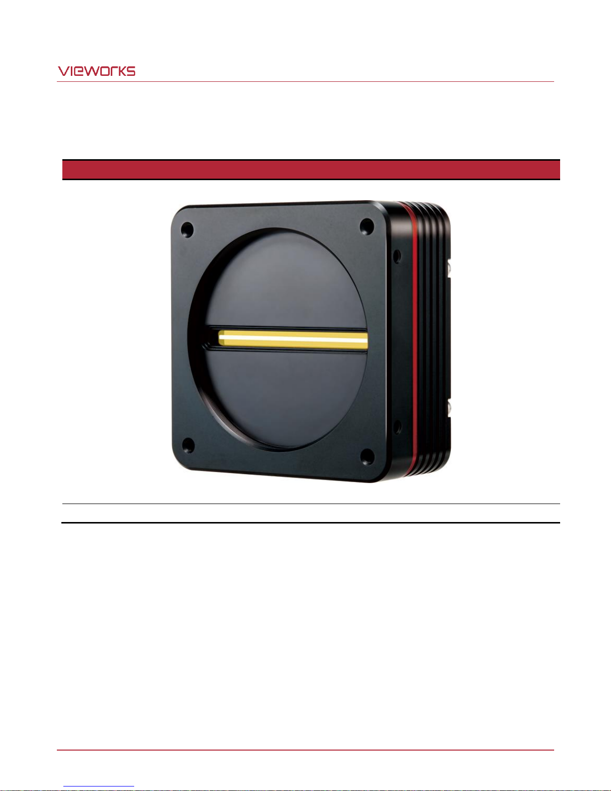
Package Components
VT Camera with M72 0.75 mount
4 Package Components
Page 9 of 77 VW40-161-001
Page 10

VT Camera Link series
5 Product Specifications
5.1 Overview
VT series, Time Delay & Integration (TDI) line scan cameras, provides faster line rates and higher sensitivity
than existing line scan cameras. Hybrid imaging sensor technology based on a combination of CCD and CMOS
circuits allows image captures with up to 128 higher sensitivity using the VT-9K7C camera. Even superior
resolution and sensitivity, up to 256 greater sensitivity can be achieved using the VT-18K3.5C camera. Its
robust Camera Link interface supports transmitting image data at up to 125 ㎑ using the VT-4K7C and VT4K14C cameras. Featured with high speed and high resolution, VT series is ideal for demanding applications
such as flat panel display inspection, wafer inspection, printed circuit board inspection, and high-performance
document scanning.
Main Features
Hybrid Line Scan
Max. 17824 256 Pixel Resolution
Bidirectional Operations with up to 256 TDI Stages
Exposure Control
Anti-blooming
Trigger Rescaler and Strobe Output Control
Camera Link Full Interface up to 120
Advanced PRNU and DSNU Correction
Area Scan Mode for Camera Alignment
Applications
Flat Panel Display Inspection
Printed Circuit Board Inspection
Wafer Inspection
High Performance Document Scanning
Page 10 of 77 VW40-161-001
Page 11
VT Camera Link series
Specification
VT-4K7C-H120
VT-4K14C-H120
VT-9K7C-H80
Active Image (H × V)
4096 × 128
4096 × 64
8912 × 128
Sensor Type
Hybrid TDI Line Scan
Pixel Size
7.0 ㎛ × 7.0 ㎛
14.0 ㎛ × 14.0 ㎛
7.0 ㎛ × 7.0 ㎛
Interface
Camera Link (Base/Medium/Full)
Pixel Data Format
8 / 10 / 12 bit
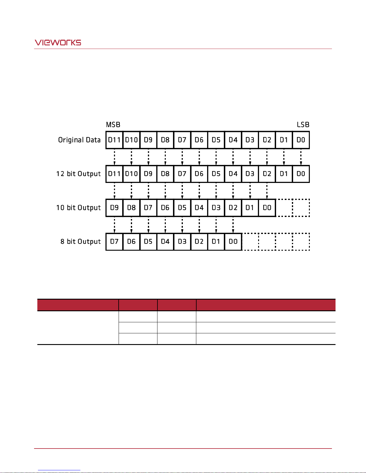
TDI Stage
32 / 64 / 96 / 128
16 / 32 / 48 / 64
32 / 64 / 96 / 128
TDI Direction
External Control Port or Programmable
Trigger Synchronization
Free-Run, External Trigger Signal, Camera Link CC1
Programmable Line Rate and Trigger Polarity
Max. Line Rate
125 ㎑
94 ㎑
Min. Line Rate
1 ㎑
Camera Link Pixel Clock
85 ㎒
Video Output
2, 4, 8 or 10 Tap
Throughput
0.51 Gpix/s
0.83 Gpix/s
Gamma Correction
User Defined LUT (Look Up Table)
Black Level
Adjustable (0 ~ 128 LSB at 8 bits)
Gain Control
Analog Gain: 0 ~ 12 ㏈
External Trigger
External, 3.3 V – 5.0 V
Power
Adapter
10 ~ 30 V DC
Dissipation
Typ. 12 W
Environmental
Ambient Operating: 0℃ ~ 40℃ (Housing: 10℃ ~ 50℃), Storage: -40℃ ~ 70℃
Mechanical
90 ㎜ × 90 ㎜ × 38 ㎜, 500 g
Configuration Software
Configurator
Optical Interface
Lens Mount
M72 × 0.75
Sensor to Camera Front
10.10 ㎜ (Optical Distance)
Sensor Alignment
Flatness
x
y
z
±25 ㎛
±0.15 ㎜
±0.15 ㎜
±0.1 ㎜
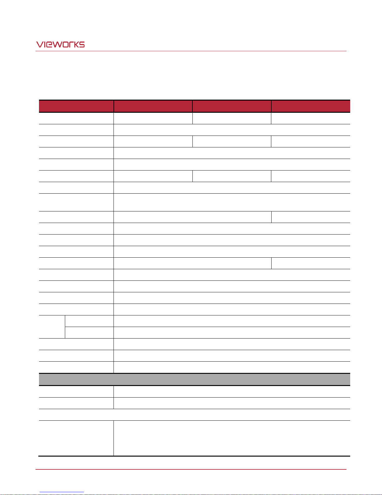
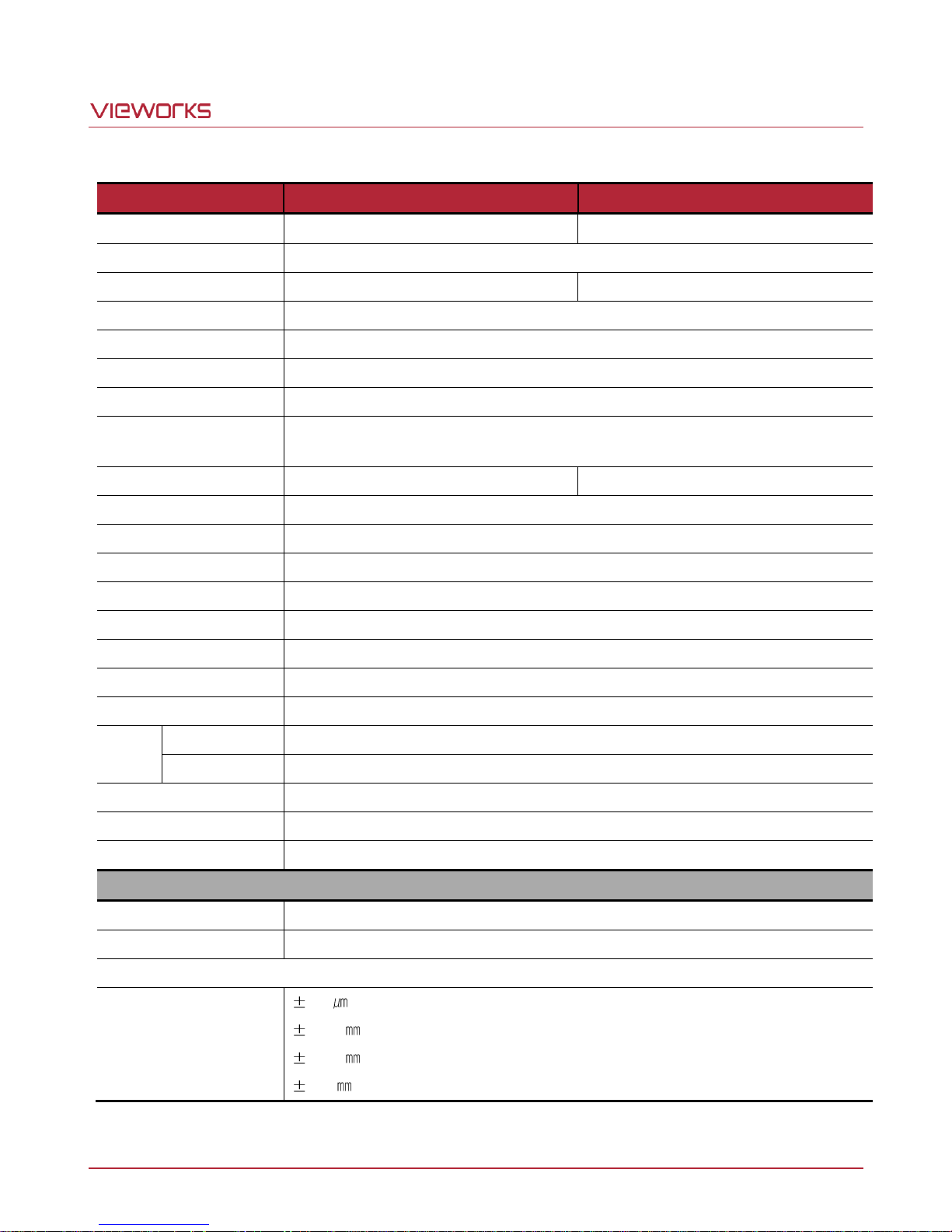
5.2 Specifications
Technical specifications for VT Camera Link series are as follows:
Page 11 of 77 VW40-161-001
Table 5.1 Specifications of VT Camera Link Series (VT-4K7C/VT-4K14C/VT-9K7C)
Page 12
VT Camera Link series
Specification
VT-12K5C-H60
VT-18K3.5C-H40
Active Image (H × V)
12480 × 256
17824 × 256
Sensor Type
Hybrid TDI Line Scan
Pixel Size
5.0 ㎛ × 5.0 ㎛
3.5 ㎛ × 3.5 ㎛
Interface
Camera Link (Base/Medium/Full)
Pixel Data Format
8 / 10 / 12 bit
TDI Stage
64 / 128 / 192 / 256
TDI Direction
External Control Port or Programmable
Trigger Synchronization
Free-Run, External Trigger Signal, Camera Link CC1
Programmable Line Rate and Trigger Polarity
Max. Line Rate
67 ㎑
47 ㎑
Min. Line Rate
1 ㎑
Camera Link Pixel Clock
85 ㎒
Video Output
2, 4, 8 or 10 Tap
Throughput
0.83 Gpix/s
Gamma Correction
User Defined LUT (Look Up Table)
Black Level
Adjustable (0 ~ 128 LSB at 8 bits)
Gain Control
Analog Gain: 0 ~ 12 ㏈
External Trigger
External, 3.3 V – 5.0 V
Power
Adapter
10 ~ 30 V DC
Dissipation
Typ. 12 W
Environmental
Ambient Operating: 0℃ ~ 40℃ (Housing: 10℃ ~ 50℃), Storage: -40℃ ~ 70℃
Mechanical
90 ㎜ × 90 ㎜ × 38 ㎜, 500 g
Configuration Software
Configurator
Optical Interface
Lens Mount
M72 × 0.75
Sensor to Camera Front
10.10 ㎜ (Optical Distance)
Sensor Alignment
Flatness
x
y
z
25
0.15
0.15
0.1
Table 5.2 Specifications of VT Camera Link Series (VT-12K5C/VT-18K3.5C)
Page 12 of 77 VW40-161-001
Page 13
VT Camera Link series
5.3 Camera Block Diagram
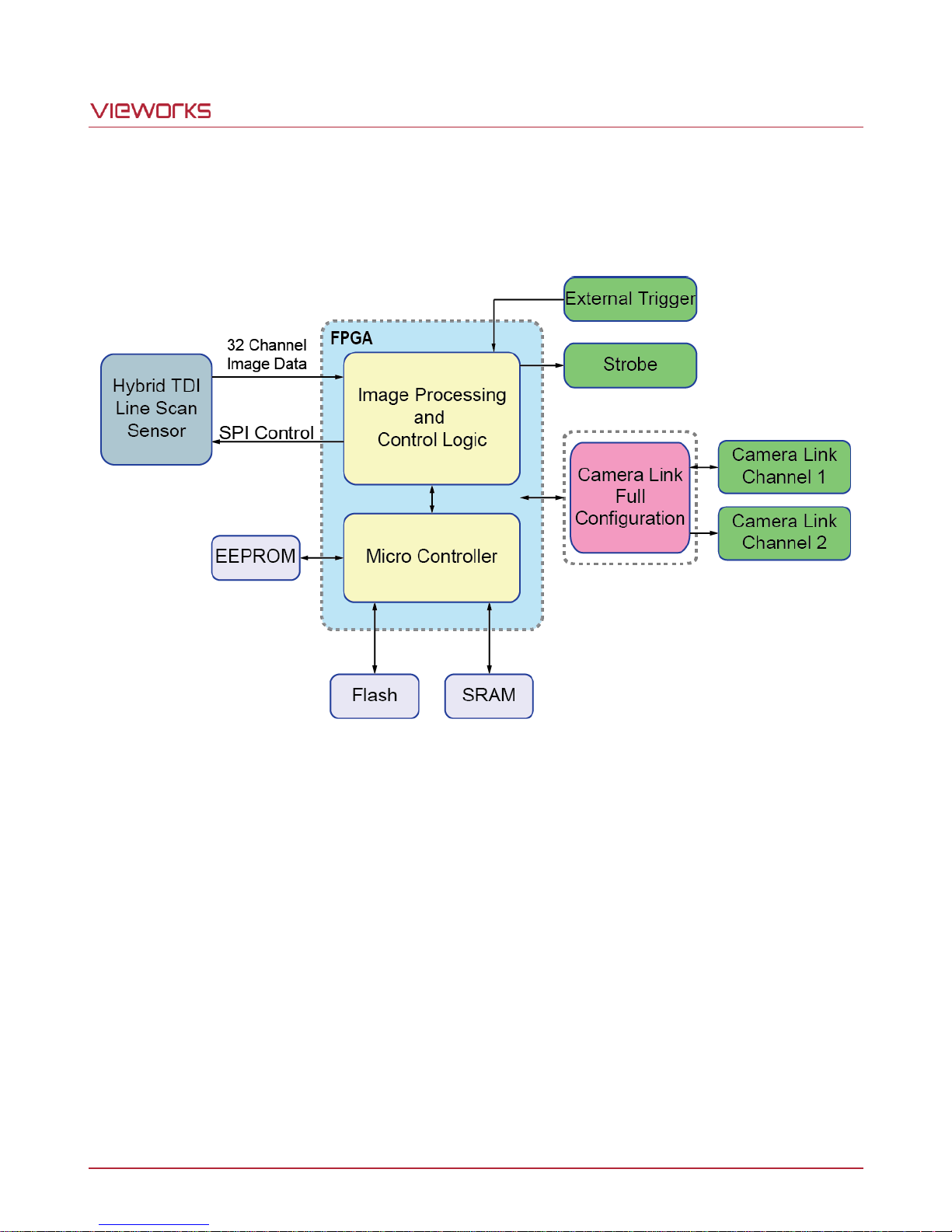
VT series consists of three printed circuit boards (PCB), and its block diagram is shown below.
Figure 5.1 Camera Block Diagram
Page 13 of 77 VW40-161-001
Page 14
VT Camera Link series
5.4 Spectral Response
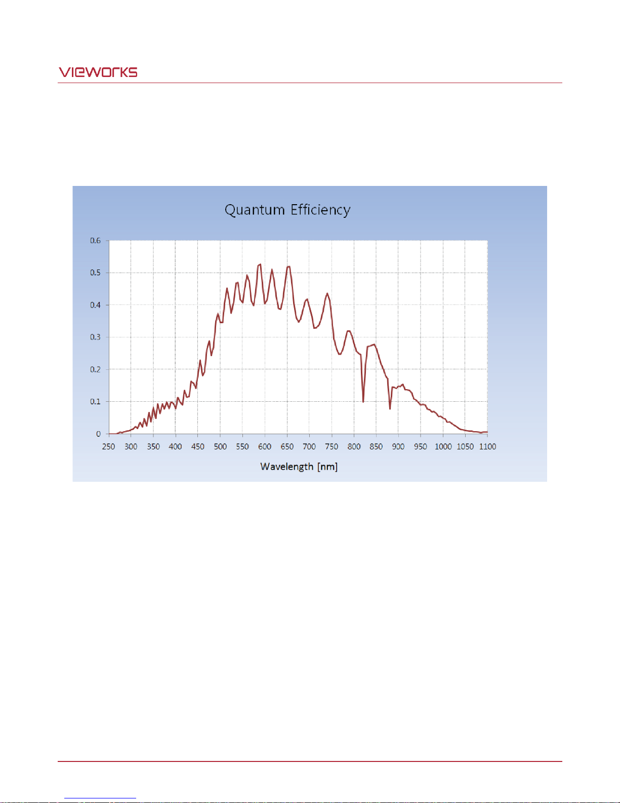
The following graph shows the spectral response for VT series.
Figure 5.2 Quantum Efficiency (Monochrome)
Page 14 of 77 VW40-161-001
Page 15
VT Camera Link series
5.5 Mechanical Specification
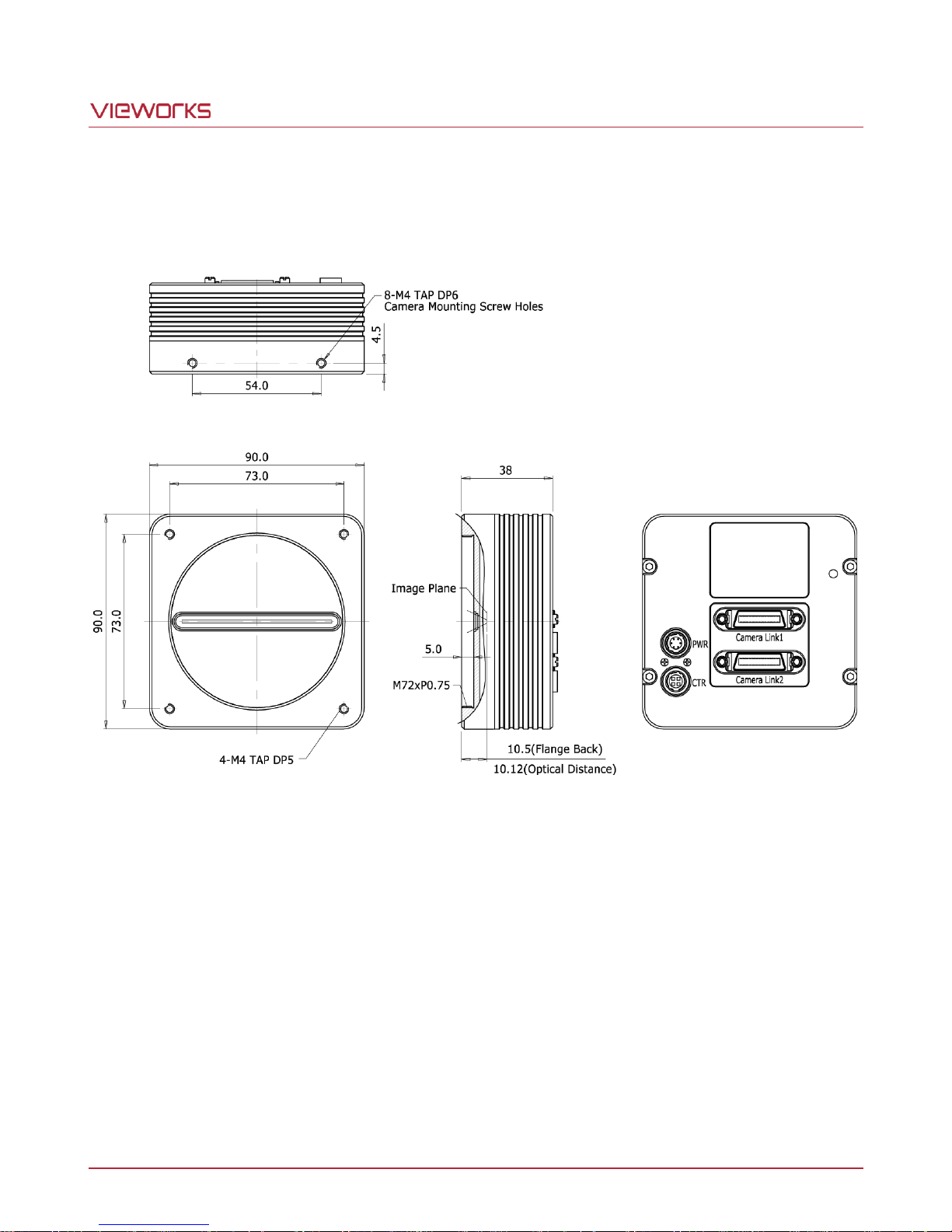
The camera dimensions in millimeters are shown in the following figure.
Figure 5.3 VT CL Series Mechanical Dimension
5.5.1 Camera Mounting and Heat Dissipation
You must mount the camera on a heat dissipation structure to maintain the temperature of the camera housing
at 50℃ or less. Given the low power consumption of the VT series camera, its housing temperature during
operation will generally stay within the specified limits. However, overheating can occur if heat dissipation is
restricted or if the camera is mounted on a severe environment. It is recommended to follow the general
guidelines below when you mount the camera.
In all cases, you should monitor the temperature of the camera housing and make sure that the temperature
does not exceed 40℃. You can monitor the internal temperature of the camera by using the ‘gct’ command.
If your camera is mounted on a metal component in your system, this may provide sufficient heat
dissipation.
Page 15 of 77 VW40-161-001
Page 16
VT Camera Link series
VT CL cameras support Camera Link Base, Medium and Full configurations. To operate the
camera in the medium or full Camera Link configuration, you must connect the camera to the
Camera Link frame grabber using two Camera Link cables. At this time, you must connect both
Camera Link1 (Base) and Camera Link2 (Medium/Full) connectors on the camera to their
respective connectors on the Camera Link frame grabber.
6 Connecting the Camera
The following instructions assume that you have installed a Camera Link frame grabber in your computer
including related software. For more information, refer to your Camera Link frame grabber user manual.
To connect the camera to your computer, follows the steps below.
1. Make sure that the power supply is not connected to the camera and your computer is turned off.
2. Plug one end of a Camera Link cable into the Camera Link1 connector on the camera and the other end of
the Camera Link cable into the Base connector on the Camera Link frame grabber.
3. Plug one end of a Camera Link cable into the Camera Link2 connector on the camera and the other end of
the Camera Link cable into the Medium/Full connector on the Camera Link frame grabber.
4. Connect the plug of the power adapter to the 6-pin power input receptacle on the camera.
5. Plug the power adapter into a working electrical outlet.
6. Verify all the cable connections are secure.
Precautions for using Camera Link Medium/Full Configuration
6.1 Precaution to Center the Imaging Sensor
Users do not need to center the imaging sensor as it is adjusted as factory default settings.
When you need to adjust the center of imaging sensor, please contact your local dealer or factory
representative for technical assistance.
6.2 Controlling the Camera
You can control the camera by using Configurator.
You can download the latest Configurator at http://www.vieworks.com.
Please refer to your Camera Link frame grabber user manual.
Page 16 of 77 VW40-161-001
Page 17
VT Camera Link series
CAMERA LINK 1
1
13
26
14
② ① ③ ④ ⑤
7 Camera Interface
7.1 General Description
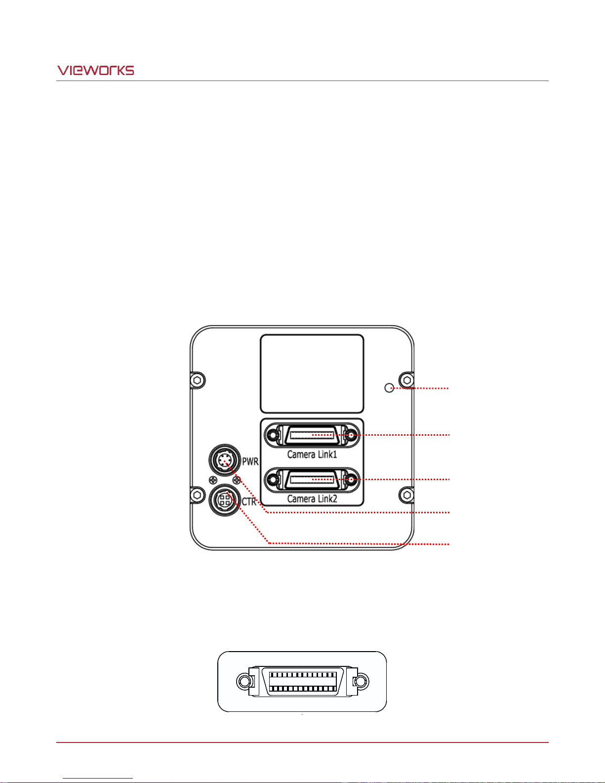
As shown in the figure below, four types of connectors and a status indicator LED are located on the back of the
camera and have the functions as follows:
① Status LED: displays power status and operation mode.
② 26 pin Camera Link1 Connector Base): controls video data transmission and the camera.
③ 26 pin Camera Link2 Connector (Medium/Full): transmits video data.
④ 6 pin Power Input Receptacle: supplies power to the camera.
⑤ 4 pin Control I/O Receptacle: provides access to the camera’s I/O lines.
Figure 7.1 VT Camera Link Series Back Panel
7.2 Camera Link Connector
Page 17 of 77 VW40-161-001
Figure 7.2 Camera Link Connector
Page 18
VT Camera Link series
PAIR List
Pin
Signal Name
Type
Description
PAIR 0
1
Ground
Ground
Cable Shield
14
Ground
Ground
Cable Shield
PAIR 1
2
-X0
LVDS - Out
Camera Link Transmitter
15
+X0
LVDS - Out
Camera Link Transmitter
PAIR 2
3
-X1
LVDS - Out
Camera Link Transmitter
16
+X1
LVDS - Out
Camera Link Transmitter
PAIR 3
4
-X2
LVDS - Out
Camera Link Transmitter
17
+X2
LVDS - Out
Camera Link Transmitter
PAIR 4
5
-XCLK
LVDS - Out
Camera Link Transmitter
18
-XCLK
LVDS - Out
Camera Link Transmitter
PAIR 5
6
-X3
LVDS - Out
Camera Link Transmitter
19
+X3
LVDS - Out
Camera Link Transmitter
PAIR 6
7
+ SerTC
LVDS - In
Serial Data Receiver
20
- SerTC
LVDS - In
Serial Data Receiver
PAIR 7
8
- SerTFG
LVDS - Out
Serial Data Transmitter
21
+ SerTFG
LVDS - Out
Serial Data Transmitter
PAIR 8
9
- CC 1
LVDS - In
Software External Trigger
22
+ CC 1
LVDS - In
Software External Trigger
PAIR 9
10
N/C
N/C
N/C
23
N/C
N/C
N/C
PAIR 10
11
N/C
N/C
N/C
24
N/C
N/C
N/C
PAIR 11
12
N/C
N/C
N/C
25
N/C
N/C
N/C
PAIR 12
13
Ground
Ground
Cable Shield
26
Ground
Ground
Cable Shield
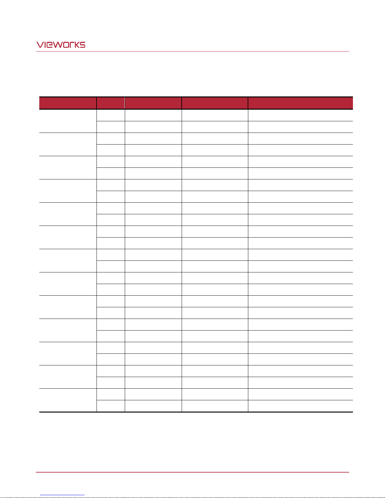
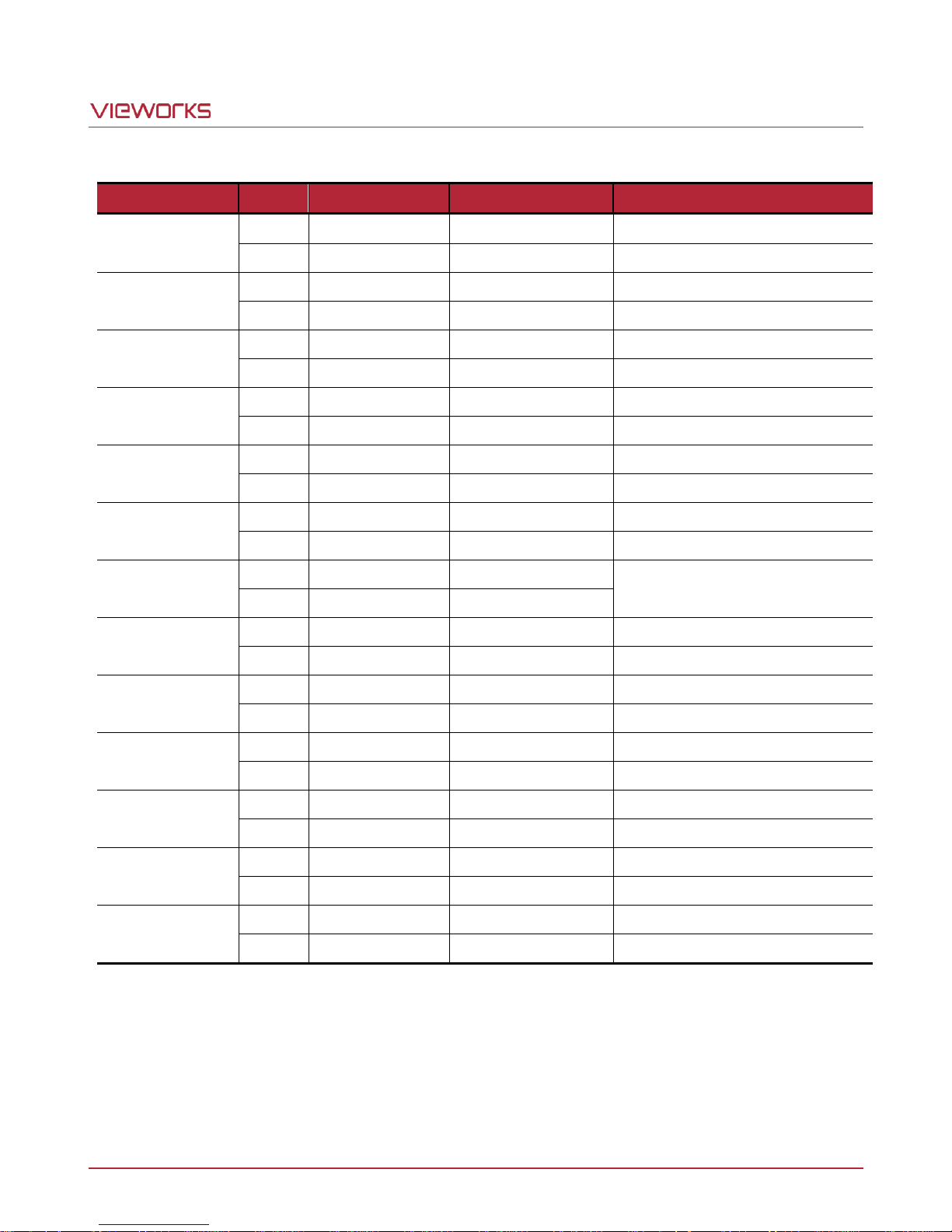
Camera Link connectors comply with Camera Link Standard and the following list shows the pin assignments of
the connector.
Table 7.1 Pin Assignments for Camera Link1 Connector
Page 18 of 77 VW40-161-001
Page 19
VT Camera Link series
PAIR List
Pin
Signal Name
Type
Description
PAIR 0
1
Ground
Ground
Cable Shield
14
Ground
Ground
Cable Shield
PAIR 1
2
-Y0
LVDS - Out
Camera Link Transmitter
15
+Y0
LVDS - Out
Camera Link Transmitter
PAIR 2
3
-Y1
LVDS - Out
Camera Link Transmitter
16
+Y1
LVDS - Out
Camera Link Transmitter
PAIR 3
4
-Y2
LVDS - Out
Camera Link Transmitter
17
+Y2
LVDS - Out
Camera Link Transmitter
PAIR 4
5
-YCLK
LVDS - Out
Camera Link Transmitter
18
+YCLK
LVDS - Out
Camera Link Clock Tx
PAIR 5
6
-Y3
LVDS - Out
Camera Link Channel Tx
19
+Y3
LVDS - Out
Camera Link Channel Tx
PAIR 6
7 - Not Used
Connected with 100 ohm
20 - Not Used
PAIR 7
8
-Z0
LVDS - Out
Camera Link Transmitter
21
+Z0
LVDS - Out
Camera Link Transmitter
PAIR 8
9
-Z1
LVDS - Out
Camera Link Transmitter
22
+Z1
LVDS - Out
Camera Link Transmitter
PAIR 9
10
-Z2
LVDS - Out
Camera Link Transmitter
23
+Z2
LVDS - Out
Camera Link Transmitter
PAIR 10
11
-ZCLK
LVDS - Out
Camera Link Transmitter
24
+ZCLK
LVDS - Out
Camera Link Clock Tx
PAIR 11
12
-Z3
LVDS - Out
Camera Link Channel Tx
25
+Z3
LVDS - Out
Camera Link Channel Tx
PAIR 12
13
Ground
Ground
Cable Shield
26
Ground
Ground
Cable Shield
Table 7.2 Pin Assignments for Camera Link2 Connector
Page 19 of 77 VW40-161-001
Page 20
VT Camera Link series
Model
Tap Mode
CL Configuration
CL1 Connector
CL2 Connector
VT Camera Link Series
2 Tap
BASE
O X 4 Tap
MEDIUM
O O 8 Tap
FULL O O
10 Tap
FULL O O
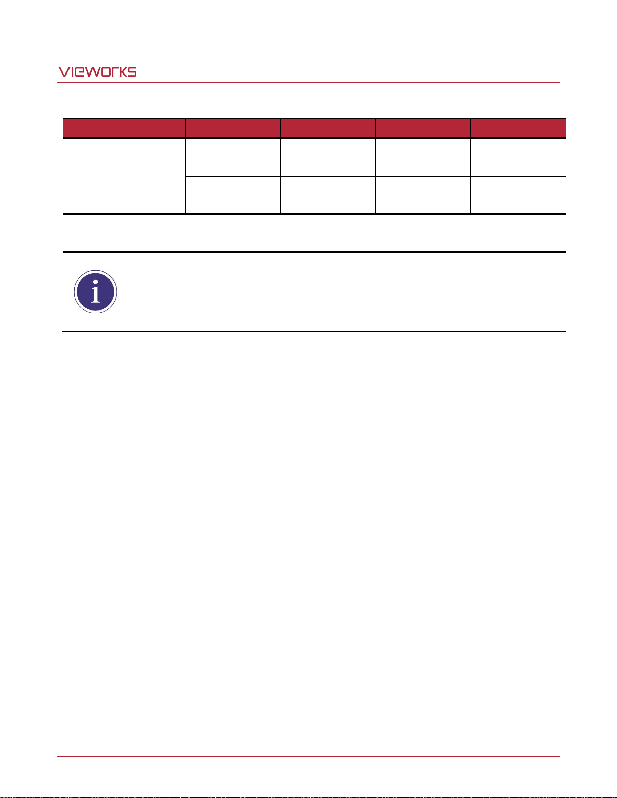
When you connect a frame grabber to Camera Link connectors on the camera using Camera
Link cables, make sure you connect to the correct Camera Link connectors. Incorrect
connection of CL1 connector and CL2 connector may cause malfunction of the camera or
communication problems between your computer and the camera.
Table 7.3 Connector Arrangement for the Camera Link Output Modes
Page 20 of 77 VW40-161-001
Page 21
VT Camera Link series
Pin Number
Signal
Type
Description
1, 2, 3
+ 12V DC
Input
DC Power Input
4, 5, 6
DC Ground
Input
DC Ground
Make sure the power is turned off before connecting the power cord to the camera.
Otherwise, damage to the camera may result.
If the voltage applied to the camera is greater than specified in the specifications, damage
to the camera my result.
1
2
3 4
5
6
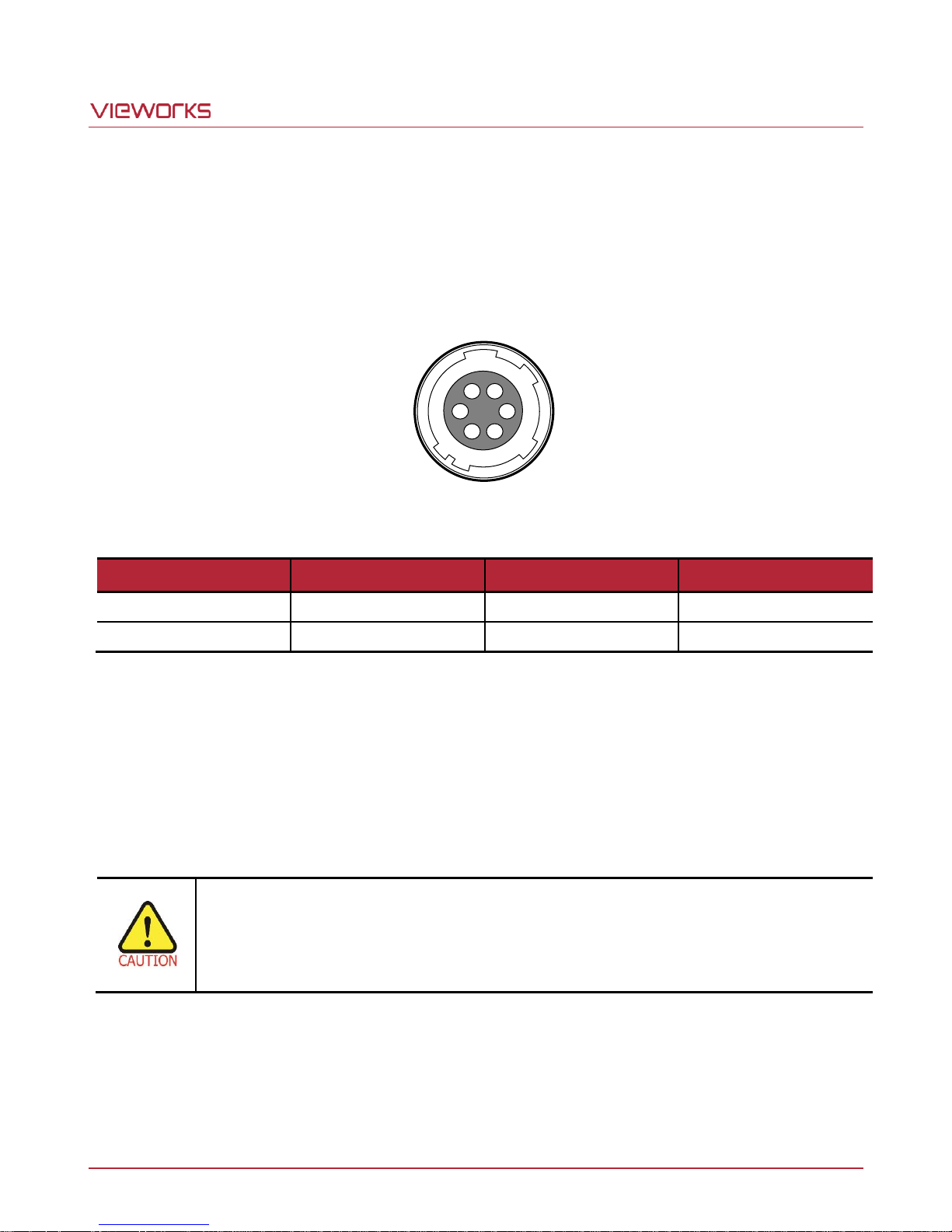
7.3 Power Input Receptacle
The power input receptacle is a Hirose 6 pin connector (part # HR10A-7R-6PB). The pin assignments and
configurations are as follows.
Figure 7.3 Pin Assignments for Power Input Receptacle
Table 7.4 Pin Configurations for Power Input Receptacle
The mating connector is a Hirose 6 pin plug (part # HR10A-7P-6S) or the equivalent connectors. The power
adapter is recommended to have at least 1 A current output at 12 V DC ±10% voltage output (Users need to
purchase the power adapter separately).
Precaution for Power Input
Page 21 of 77 VW40-161-001
Page 22
VT Camera Link series
Pin Number
Signal
Type
Description
1
Trigger Input
Input
3.3 V ~ 5.0 V TTL input
2
Scan Direction Input
Input
3.3 V ~ 5.0 V TTL input
3
DC Ground
-
DC Ground
4
Strobe Out
Output
3.3 V TTL Output
Output resistance: 47 Ω
1
2
4
3
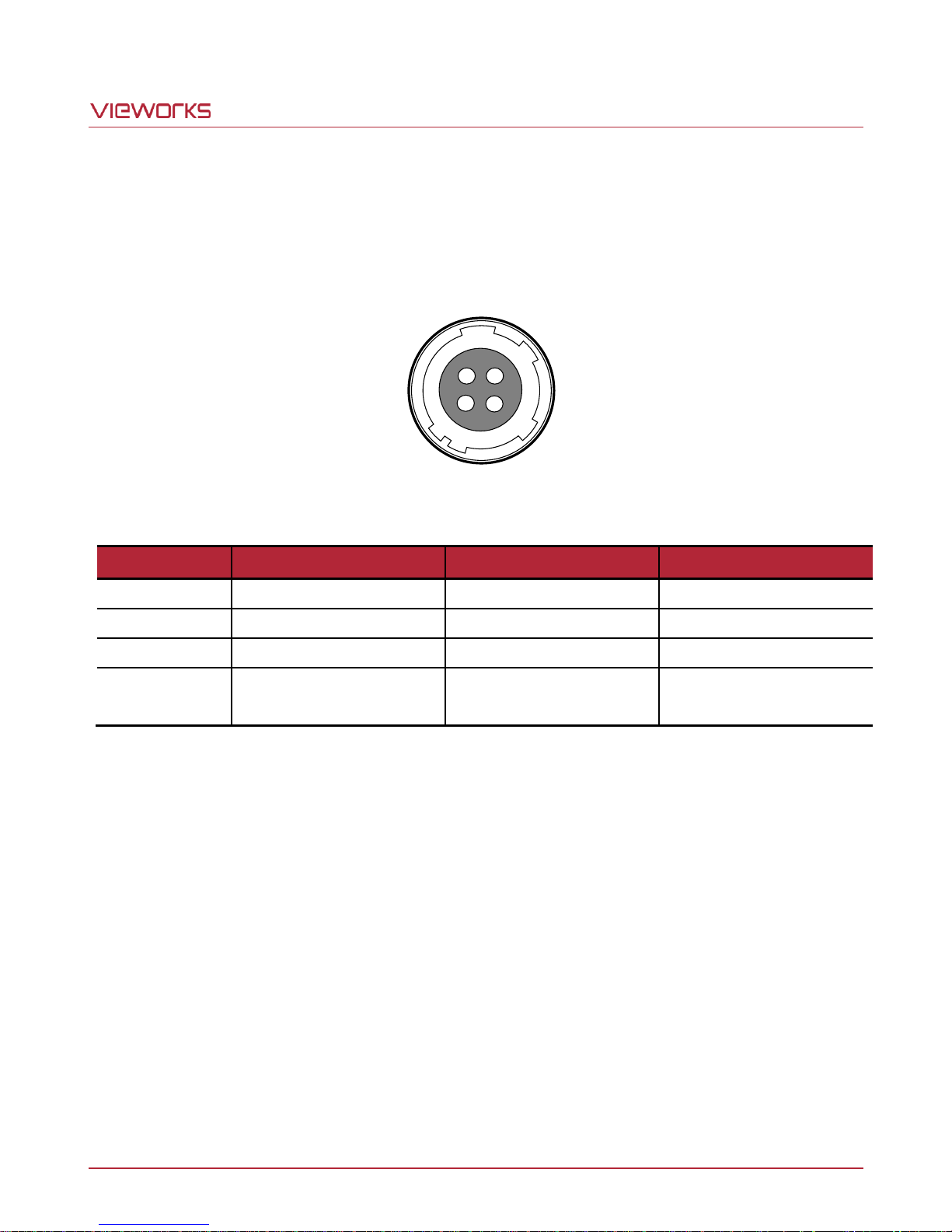
7.4 Control I/O Receptacle
The control I/O receptacle is a Hirose 4-pin connector (part # HR10A-7R-4S) and consists of an external trigger
signal input and strobe output ports. The pin assignments and configurations are as follows.
Figure 7.4 Pin Assignments for Control I/O Receptacle
Table 7.5 Pin Configurations for Control I/O Receptacle
The mating connector is a Hirose 4 pin plug (part # HR10A-7P-4P) or the equivalent connectors.
Page 22 of 77 VW40-161-001
Page 23
VT Camera Link series
②
③
④
①
HR 10A-7R-4SB
Camera
USER
47 Ω
47 Ω
Trigger Input
Direction Input
Ground Signal
Trigger Input(LineIn0)
Direction Input (LineIn1)
Input High Level( 2 ~ 5V)
input Low Level ( 0 ~ 0.8 V)
②
③
④
①
HR 10A-7R-4SB
47 Ω
Strobe OutStrobe Out
Ground Signal
Camera
USER
3.3V
0V
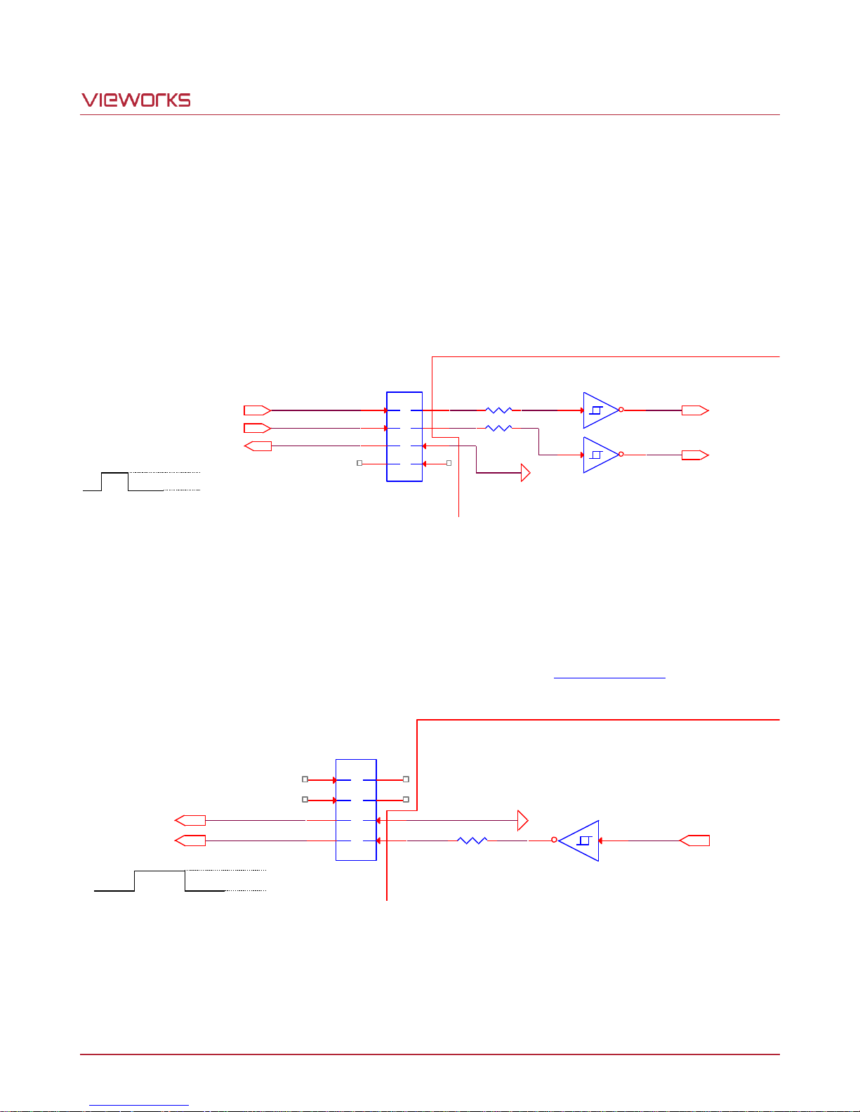
7.5 Trigger / Direction Input Circuit
The following figure shows trigger signal input and TDI direction input circuit of the 4 pin connector. Transmitted
trigger signal and TDI direction signal is applied to the internal circuit through a CMOS buffer with a good noise
margin. The minimum trigger width that can be recognized by the camera is 1 ㎲. If transmitted trigger signal is
less than 1 ㎲, the camera will ignore the trigger signal. An external trigger and TDI direction circuit example is
shown below.
Figure 7.5 Trigger / Direction Input Schematic
7.6 Strobe Output Circuit
The strobe output signal comes out through a 3.3 V output level of Line Driver IC. A pulse width of the signal is
synchronized with a Line Start trigger (shutter) signal of the camera (refer to 9.12 Strobe Mode).
Page 23 of 77 VW40-161-001
Figure 7.6 Strobe Output Schematic
Page 24
VT Camera Link series
Free Run
When you set the Trigger Mode parameter to OFF, the camera will generate all required trigger
signals internally. When the camera is set this way, it will constantly acquire images without any
need for triggering by the user. This use case is commonly known as “free run”.
8 Acquisition Control
This chapter provides detailed information about the following elements involved with the image acquisition.
Line Start Trigger – Trigger Mode
Line Rate Control
8.1 Line Start Trigger
The Line Start trigger is used to begin line acquisition. Line Start trigger signals can be generated within the
camera or may be applied externally by setting the Source parameter to CC1 or External. If a line start trigger
signal is applied to the camera, the camera will begin to acquire images.
8.1.1 Trigger Mode
The main parameter associated with the line start trigger is the Trigger Mode parameter. The Trigger Mode
parameter for the line start trigger has two available settings: OFF and ON.
8.1.1.1 Trigger Mode = OFF
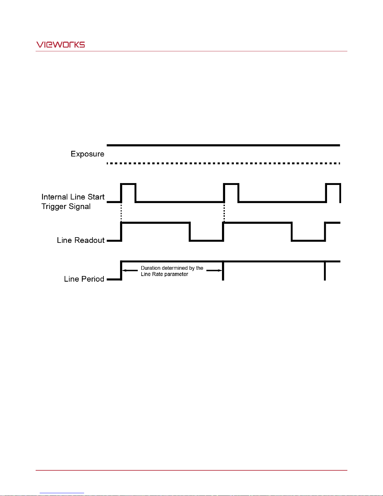
When the Trigger Mode parameter is set to OFF, the camera will generate all required line start trigger signals
internally, and you do not need to apply line start trigger signals to the camera.
If the Trigger Mode parameter is set to OFF, the camera will automatically begin generating line start signals.
Page 24 of 77 VW40-161-001
Page 25
VT Camera Link series
The rate at which the line start trigger signals are generated may be determined by the camera’s Line Rate
parameter.
If the parameter is set to a value less than the maximum allowed line rate with the current camera settings,
the camera will generate line start trigger signals at the rate specified by the parameter setting.
If the parameter is set to a value greater than the maximum allowed line rate with the current camera
settings, the camera will generate line start trigger signals at the maximum allowed line rate.
Figure 8.1 Trigger Mode = OFF
Page 25 of 77 VW40-161-001
Page 26
VT Camera Link series
8.1.1.2 Trigger Mode = ON
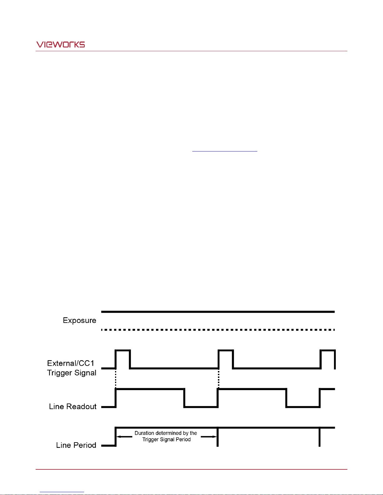
When the Trigger Mode parameter is set to ON, you must apply a line start trigger signal to the camera each
time you want to begin an image acquisition. The Source parameter specifies the source signal that will act as
the line start trigger signal.
The available settings for the Source parameter are:
External: You can apply a line start trigger signal to the camera by injecting an externally generated
electrical signal (commonly referred to as a hardware or external trigger signal) into the Control
I/O receptacle on the camera. Refer to 7.5 Trigger Input Circuit for more information.
CC1: You can apply a line start trigger signal via CC1 port of the Camera Link frame grabber.
For more information, refer to your Camera Link frame grabber user manual.
After setting the Source parameter, you must also set the Activation parameter.
The available settings for the Activation parameter are:
Rising: Specifies that a rising edge of the electrical signal will act as the line start trigger.
Falling: Specifies that a falling edge of the electrical signal will act as the line start trigger.
Both: Specifies that both rising and falling edges of the electrical signal will act as the line start
trigger.
When the Trigger Mode parameter is set to ON, the camera’s line rate can be controlled by manipulating the
external trigger signal. At this point, it is important that you do not attempt to trigger images at a rate that is
greater than the maximum allowed.
Page 26 of 77 VW40-161-001
Figure 8.2 Trigger Mode = ON
Page 27
VT Camera Link series
8.1.2 Using an External/CC1 Trigger Signal
If the Trigger Mode parameter is set to ON and the Source parameter is set to External or CC1, you must
apply an external or CC1 trigger signal to the camera to begin image acquisition.
To apply trigger signals via CC1 port of the Camera Link frame grabber, you must set the Source parameter to
CC1. At that point, each time a proper CC1 trigger signal is applied to the camera by using the APIs provided by
a Camera Link frame grabber manufacturer, the line start trigger signal will be applied to the camera.
For more information, refer to your Camera Link frame grabber user manual.
To apply trigger signals via hardware (external), you must set the Source parameter to External. At that point,
each time a proper electrical signal is applied to the camera, an occurrence of the line start trigger signal will be
recognized by the camera.
A rising edge and/or a falling edge of the external or CC1 signal can be used to trigger image acquisition.
The Activation parameter is used to select rising edge and/or falling edge triggering.
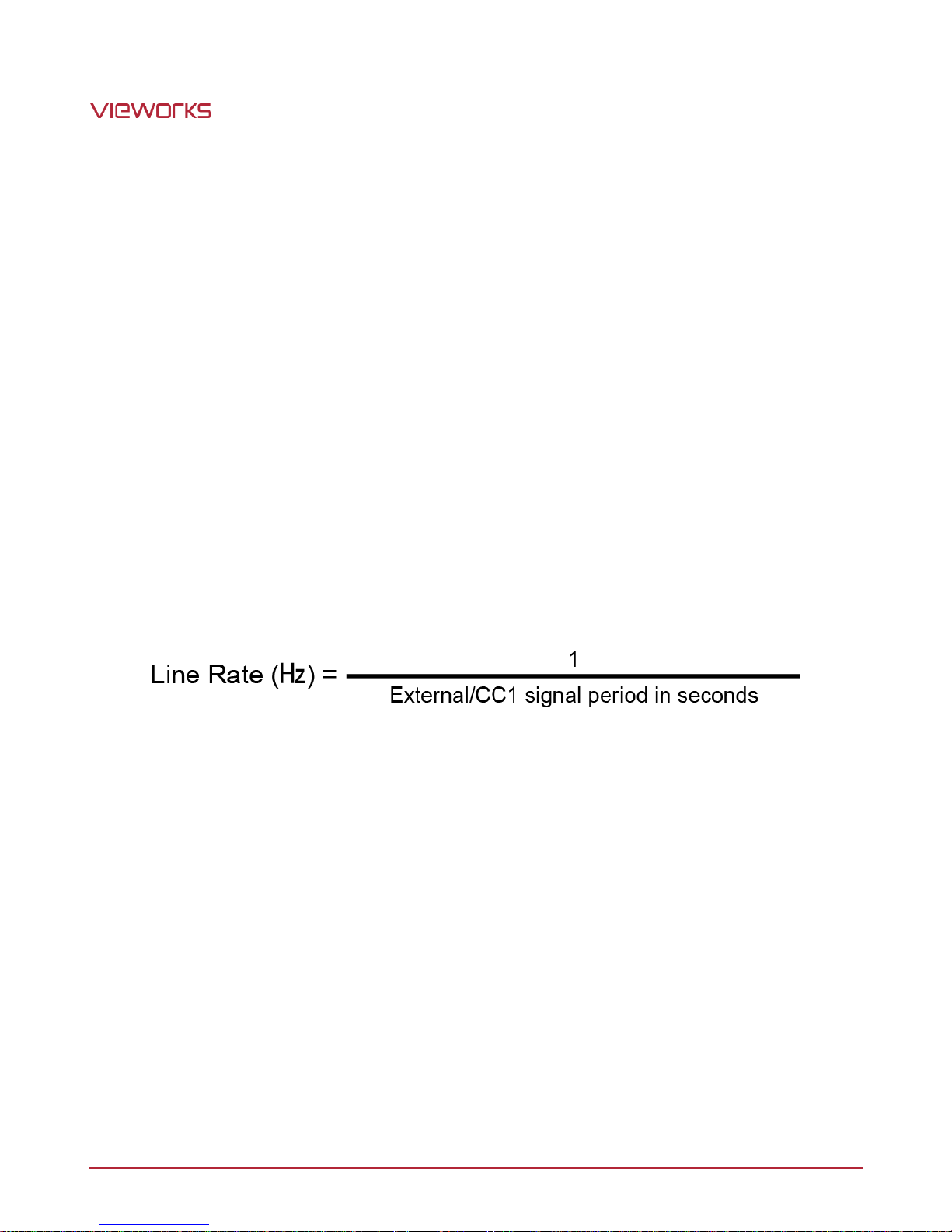
When the camera is operating under control of an external or CC1 signal, the period of trigger signal will
determine the rate at which the camera is acquiring images:
For example, if you are operating a camera with an external trigger signal period of 20 ㎲(0.00002 s):
So in this case, the line rate is 50 ㎑.
Page 27 of 77 VW40-161-001
Page 28
VT Camera Link series
Configurator Parameters
Command
Value
Description
Rescaler Mode
srm 0
Off
Disables Rescaler Mode.
srm 1
On
Enables Rescaler Mode.
Rescale Rate
srr f
0.010000 ~ 100.000000
Set the trigger rescaler rate for
converting trigger signals.
f: Float, 0.010000 ~ 100.000000
Rescaler Filter
srf 0
16
Set the rescaler filter factor to
decrease the jitter of the external
trigger signals.
srf 1
32
srf 2
64
srf 3
128
srf 4
256
srf 5
512
8.1.3 Rescaler Mode
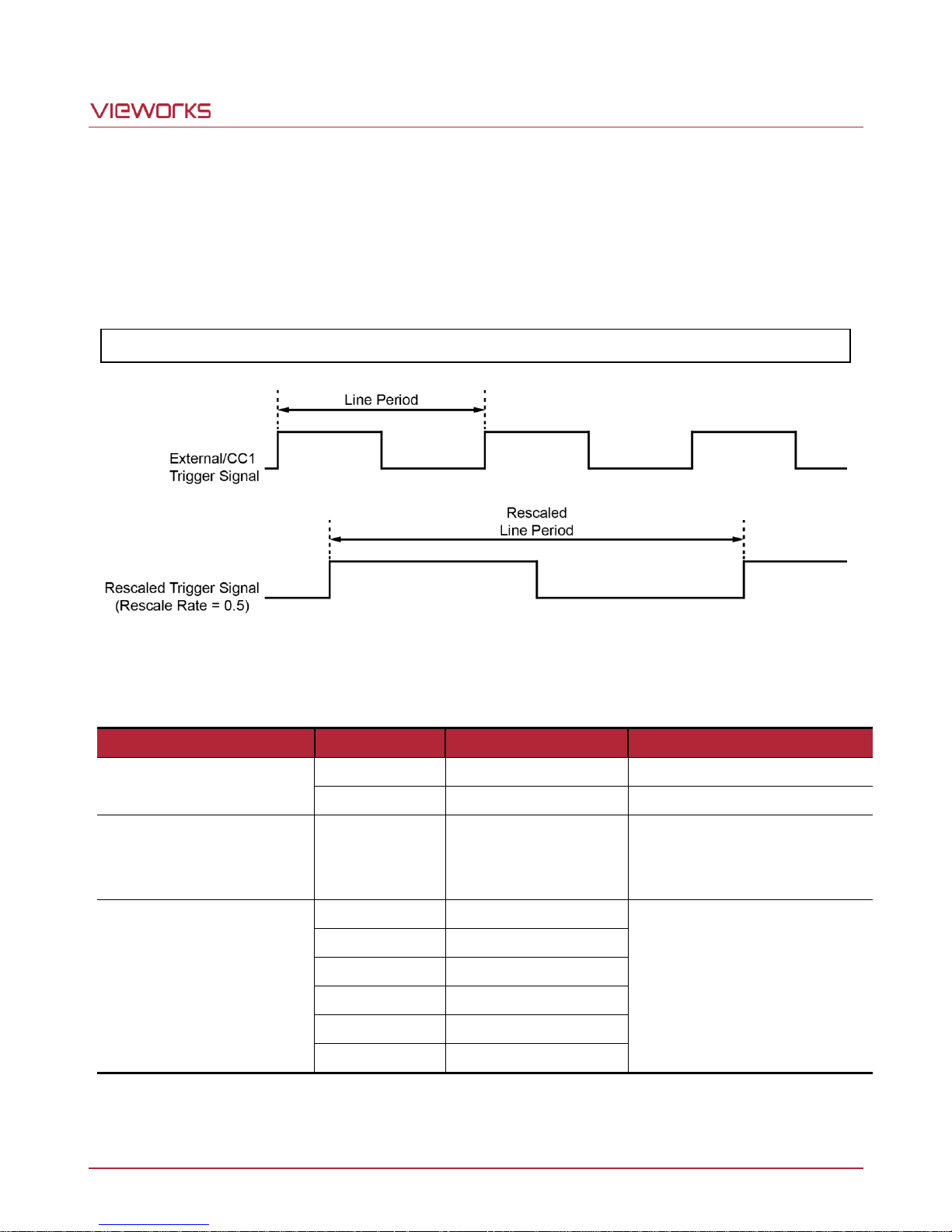
In the Rescaler Mode, you can modulate the period of the external trigger signal as desired. For example, if you
supply the external trigger signal into the camera’s I/O receptacle using the conveyor’s encoder, the number of
output pulses per revolution of the encoder is fixed. In this situation, you can modulate the period of the trigger
signal received from the camera in the following manner to match the pitch of the image in vertical direction.
Line Rate (㎐) = External Trigger Line Rate × Rescale Rate
Figure 8.3 Rescale Rate = 0.5
The commands related to the Rescaler Mode are as follows.
Table 8.1 Commands related to Rescaler Mode
Page 28 of 77 VW40-161-001
Page 29
VT Camera Link series
Tap Mode
VT-4K7C / VT-4K14C
VT-9K7C
VT-12K5C
VT-18K3.5C
2 Tap
41.3 ㎑
19.0 ㎑
13.5 ㎑
9.5 ㎑
4 Tap
82.1 ㎑
38.0 ㎑
27.1 ㎑
19.0 ㎑
8 Tap
125.0 ㎑
75.7 ㎑
54.2 ㎑
38.0 ㎑
10 Tap
125.0 ㎑
94.5 ㎑
67.6 ㎑
47.4 ㎑
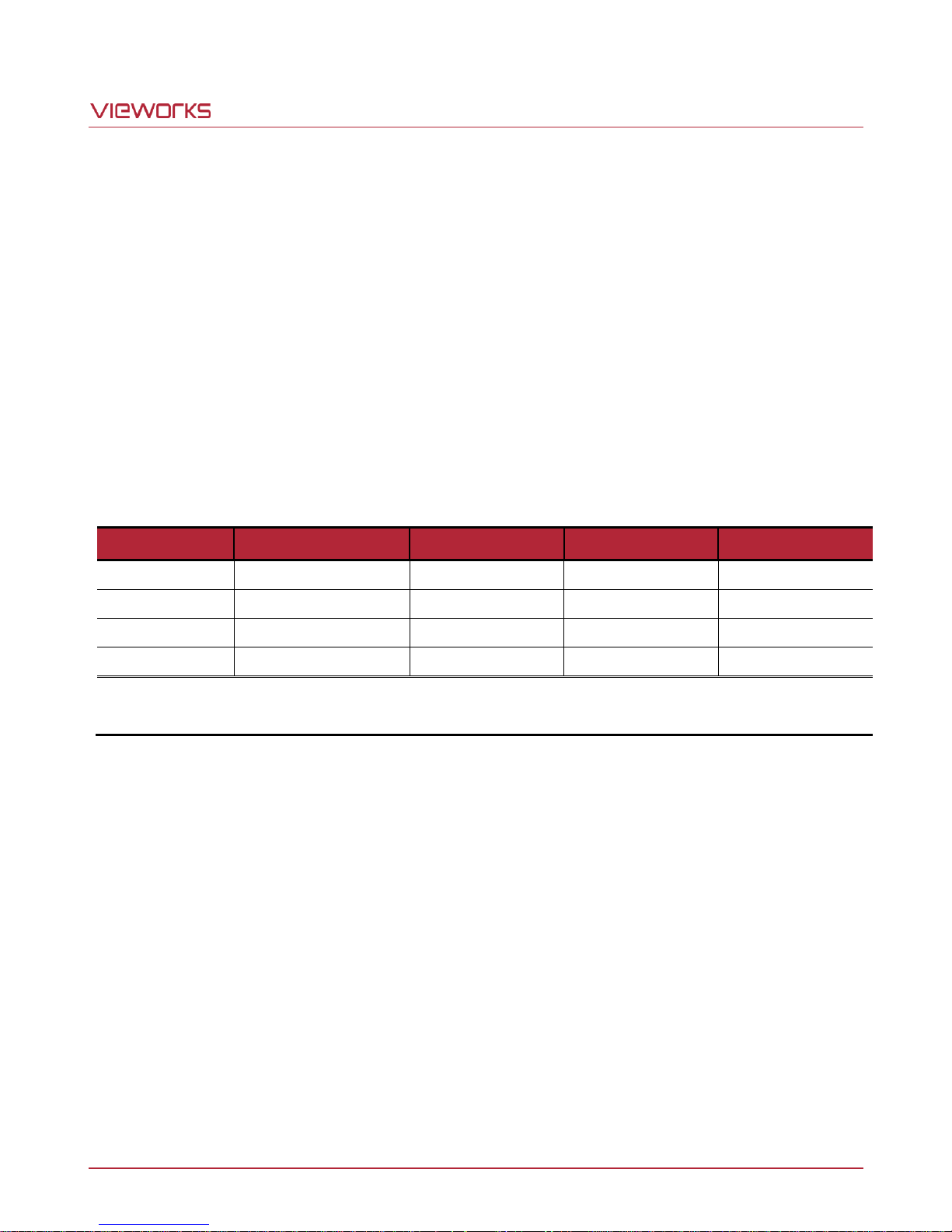
When the camera is set for 4 Tap Mode (CL Medium), 8 Tap Mode (CL Full) or 10 Tap Mode (CL Full), you
must connect the camera to the Camera Link frame grabber using two Camera Link cables.
8.2 Maximum Allowed Line Rate
In general, the maximum allowed acquisition line rate on the camera may be limited by the following factors:
Camera Link Tap Configuration (Tap Mode) Settings.
When the camera is set for a Tap Mode that uses more taps, it will take less time to transfer acquired
images from the camera to the Camera Link frame grabber in your computer. For example, if the camera is
set to 8 Tap (Camera Link Full Configuration), it can typically transfer data out of the camera two times
faster than when the camera is set to 4 Tap (Camera Link Medium).
The exposure time for acquired line images. If you use very long exposure times, you can acquire fewer line
images per second.
The maximum allowed line rates for each model are as follows:
Table 8.2 Maximum Allowed Line Rates for Each Camera Model
Page 29 of 77 VW40-161-001
Page 30
VT Camera Link series
Configurator Parameter
Command
Value
Description
Operation Mode
som 0
TDI
Operates the camera in the TDI mode.
som 1
Area
Operates the camera in the Area mode.
9 Camera Features
9.1 Operation Mode
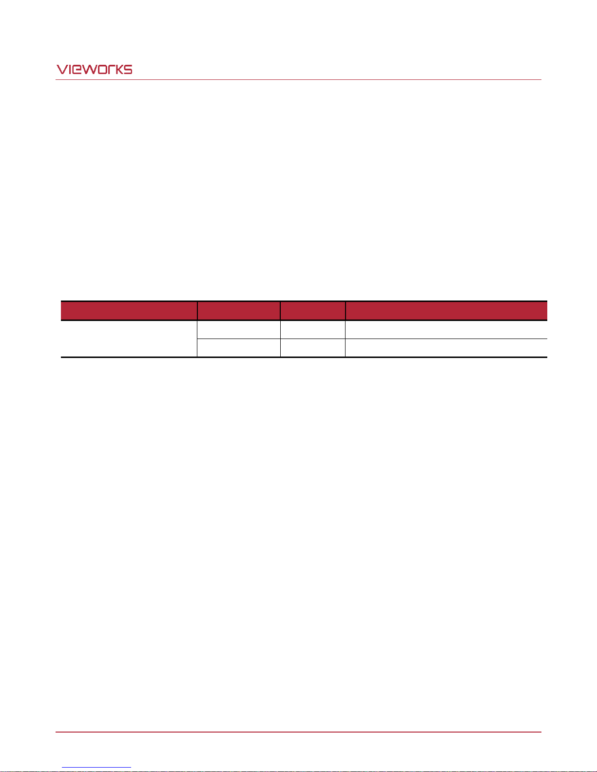
The VT Camera Link cameras have two different operation modes: Area and TDI (Time Delay and Integration).
If the Operation Mode parameter is set to Area, the camera will operate as an area scan camera using two
dimensional array of pixels. This mode is useful for aligning the camera to your target object.
If the Operation Mode parameter is set to TDI, the camera will operate as a high sensitivity line scan camera
and provide up to 256 higher sensitivity than existing line scan cameras.
The commands related to the Operation Mode are as follows.
Table 9.1 Commands related to Operation Mode
Page 30 of 77 VW40-161-001
Page 31
VT Camera Link series
Configurator Parameter
Command
Value
Description
TDI Stages
std 1
16
Sets the number of TDI Stages to 16.
std 2
32
Sets the number of TDI Stages to 32.
std 3
48
Sets the number of TDI Stages to 48.
std 4
64
Sets the number of TDI Stages to 64.
Configurator Parameter
Command
Value
Description
TDI Stages
std 1
32
Sets the number of TDI Stages to 32.
std 2
64
Sets the number of TDI Stages to 64.
std 3
96
Sets the number of TDI Stages to 96.
std 4
128
Sets the number of TDI Stages to 128.
Configurator Parameter
Command
Value
Description
TDI Stages
std 1
64
Sets the number of TDI Stages to 64.
std 2
128
Sets the number of TDI Stages to 128.
std 3
192
Sets the number of TDI Stages to 192.
std 4
256
Sets the number of TDI Stages to 256.
9.2 TDI Stages
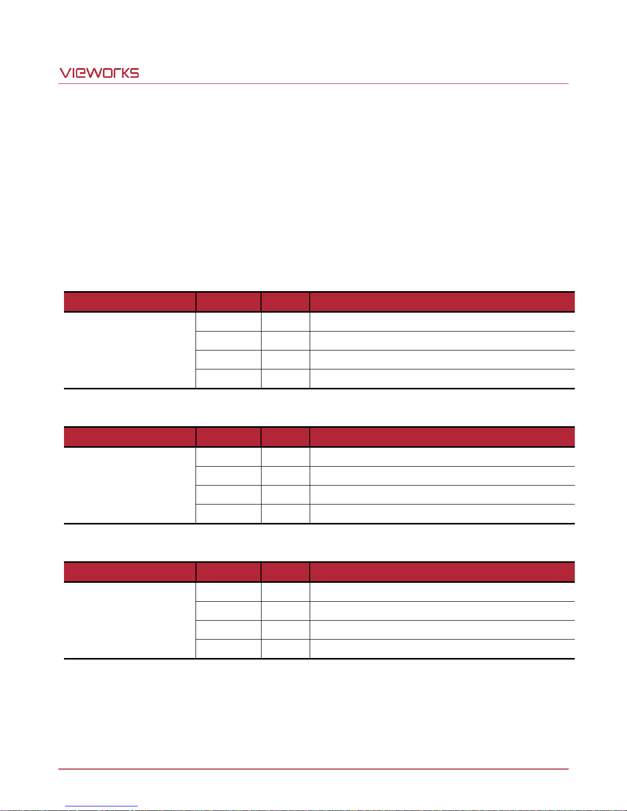
In the TDI mode, the TDI Stages parameter is used to determine the number of integration stages used by the
camera. For example, if the TDI Stages parameter is set to 256, the camera will acquire images with 256
higher sensitivity.
In the Area mode, the TDI Stages parameter is used to determine the height of the imaging sensor. For
example, if the Operation Mode parameter is set to Area and the TDI Stages parameter is set to 256 on the
VT-18K3.5C-H40 camera, the camera will acquire area images.
The commands related to the TDI Stages are as follows.
Table 9.2 Commands related to TDI Stages (VT-4K14C)
Table 9.3 Commands related to TDI Stages (VT-4K7C/VT-9K7C)
Table 9.4 Commands related to TDI Stages (VT-12K5C/VT-18K3.5C)
Page 31 of 77 VW40-161-001
Page 32
VT Camera Link series
Camera Model
Available TDI Stage Values
VT-4K7C-H120
32 / 64 / 96 / 128
VT-4K14C-H120
16 / 32 / 48 / 64
VT-9K7C-H80
32 / 64 / 96 / 128
VT-12K5C-H60
64 / 128 / 192 / 256
VT-18K3.5C-H40
64 / 128 / 192 / 256
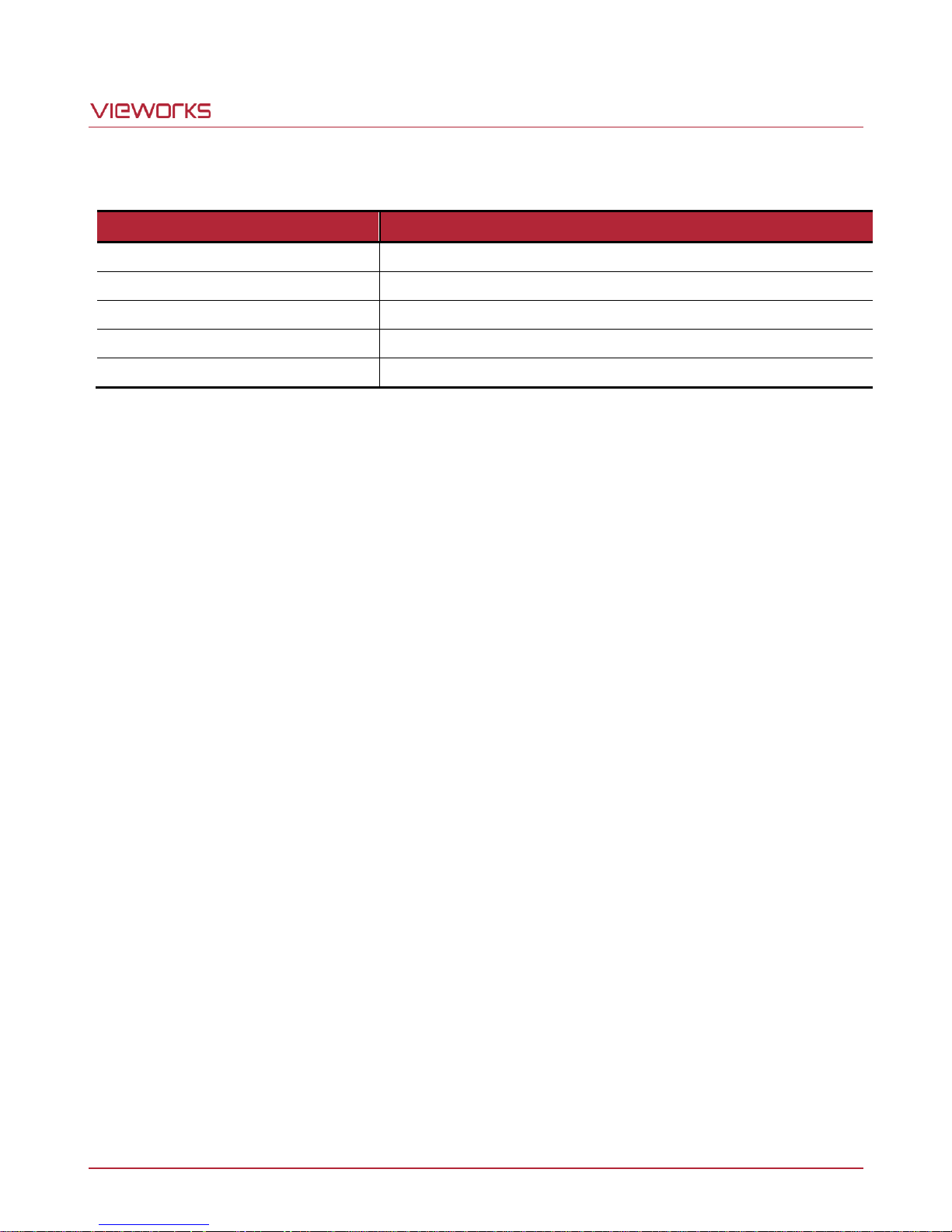
The number of available TDI Stages for each camera model is as follows.
Table 9.5 Available TDI Stage Values for each Camera Model
Page 32 of 77 VW40-161-001
Page 33
VT Camera Link series
Configurator Parameter
Command
Value
Description
Direction
ssd 0
Forward
Scan images in the forward direction.
ssd 1
Reverse
Scan images in the reverse direction.
ssd 2
Line 1
Selects the scan direction using an external signal.
9.3 Direction
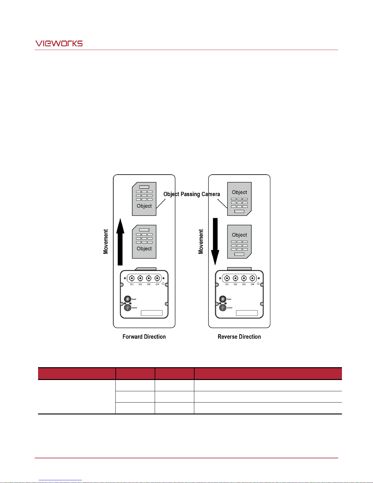
In the TDI mode, the Direction parameter is used to select the imaging sensor’s scan direction. You need to set
the Direction parameter to Forward if the object being images will pass the bottom of the camera, and then
pass the top of the camera. On the contrary, you need to set the Direction parameter to Reverse if the object
being imaged pass the top of the camera, and then pass the bottom of the camera.
When you set the Direction parameter to Line 1, you can also select the scan direction by injecting an
externally generated electrical signal (Low = Forward, High = Reverse) into the Control I/O receptacle on the
camera.
Table 9.6 Commands related to Direction
When you set the Direction parameter to Reverse in the Area mode, you can acquire vertically flipped images.
Page 33 of 77 VW40-161-001
Figure 9.1 Direction
Page 34
VT Camera Link series
Your Camera Link frame grabber may place additional restrictions on how the ROI location and
size must be set. Refer to your Camera Link frame grabber user manual for more information.
9.4 Region of Interest
The Region of Interest (ROI) feature allows you to specify a portion of the sensor lines. During operation, only
the pixel information from the specified portion of the lines are read out of the sensor and transmitted from the
camera to the frame grabber.
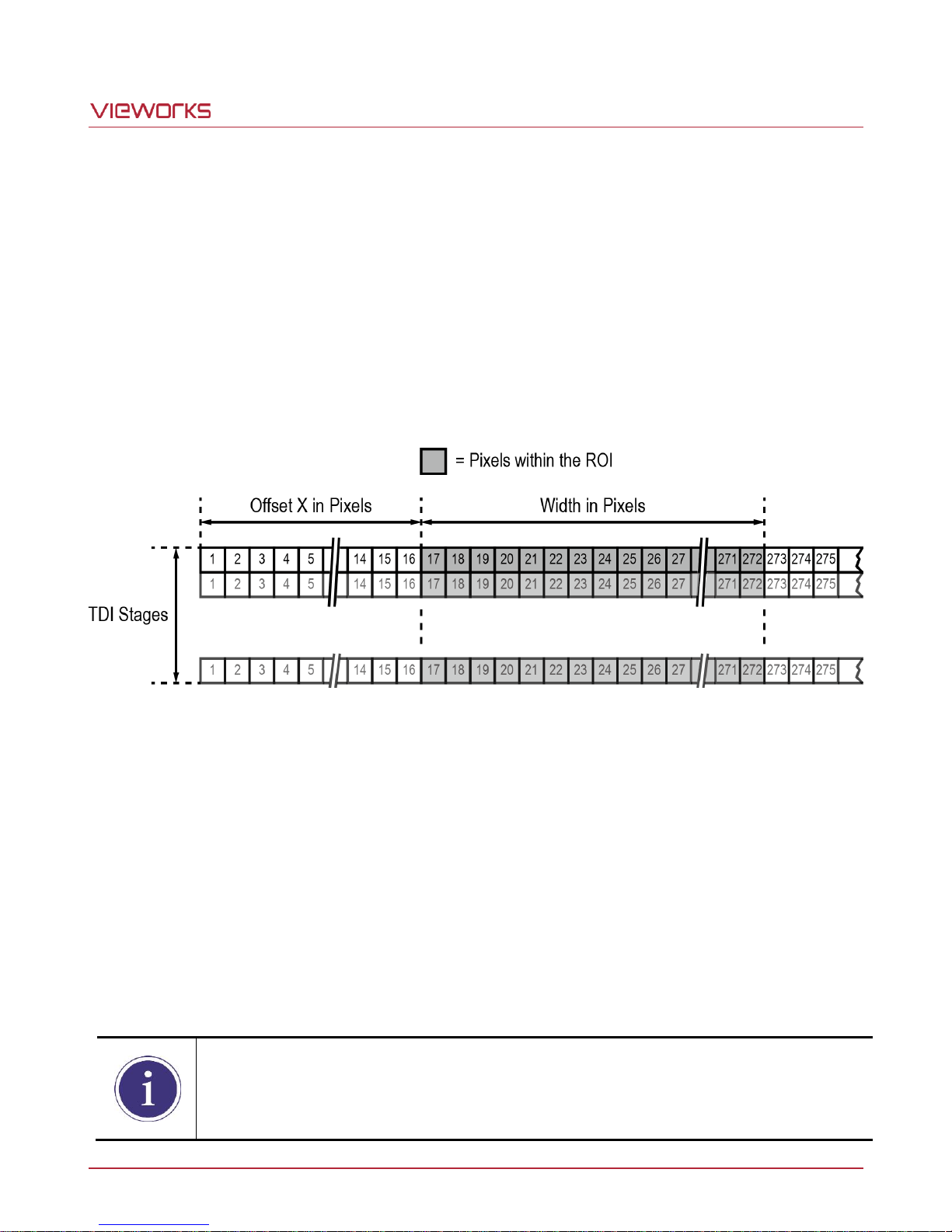
The ROI is referenced to the left end of the sensor array. The location and size of the ROI is defined by declaring
the Offset X and Width settings. For example, suppose that you set the Offset X parameter to 16 and the Width
parameter to 256 as shown in the figure below. With these settings, the camera will read out and transmit pixel
values for pixels 17 through 272.
Figure 9.2 Region of Interest
9.4.1 Setting the ROI
By default, the ROI is set to use the full resolution of the camera’s imaging sensor. You can change the size and
location of the ROI by changing the Offset X and Width parameter values.
When you are setting the camera’s region of interest, you must consider the following guidelines:
The sum of the Offset X and Width setting values must not exceed the width of the camera’s imaging
sensor. For example, on the VT-12K5C camera, the sum of the Offset X and Width setting values must not
exceed 12480.
The Offset X setting value can be set to 0 and can be increased in increments of 16. The Width setting
values must be a minimum of 256 and can be set to a multiple of 16.
Page 34 of 77 VW40-161-001
Page 35
VT Camera Link series
Width
VT-4K7C / VT-4K14C
VT-9K7C
VT-12K5C
VT-18K3.5C
4096
125.0 ㎑
125.0 ㎑
100.0 ㎑
80.0 ㎑
6000
-
112.1 ㎑
100.0 ㎑
80.0 ㎑
8192
-
82.3 ㎑
82.3 ㎑
80.0 ㎑
8912
-
75.7 ㎑
75.7 ㎑
75.7 ㎑
12000 - -
56.3 ㎑
56.3 ㎑
12480 - -
54.2 ㎑
54.2 ㎑
16384 - -
-
41.3 ㎑
17824 - -
-
38.0 ㎑
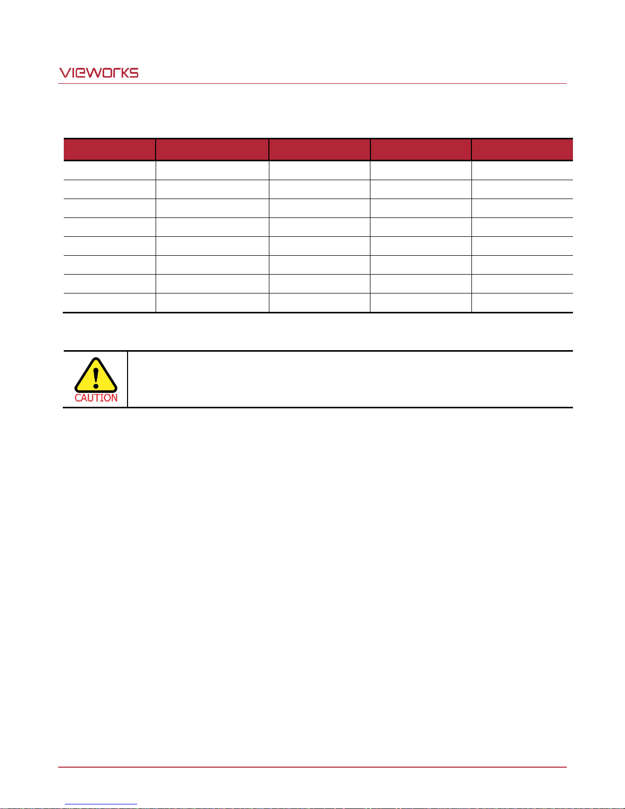
To acquire images at the maximum allowed line rate, you need to set the camera’s Tap Mode to
10 Tap (Camera Link Full Configuration). In this case, you must connect the camera to the
Camera Link frame grabber using two Camera Link cables.
The maximum allowed line rates depending on the ROI settings for each camera model are as follows.
Table 9.7 Maximum Allowed Line Rates depending on ROI Settings (8 Tap Mode)
Page 35 of 77 VW40-161-001
Page 36
VT Camera Link series
Configurator Parameters
Command
Value
Description
Binning H
sbh 1
×1
Disables the Horizontal Binning.
sbh 2
×2
Combines two adjacent pixels in horizontal direction.
Binning V
sbv 1
×1
Disables the Vertical Binning.
sbv 2
×2
Combines two adjacent pixels in vertical direction.
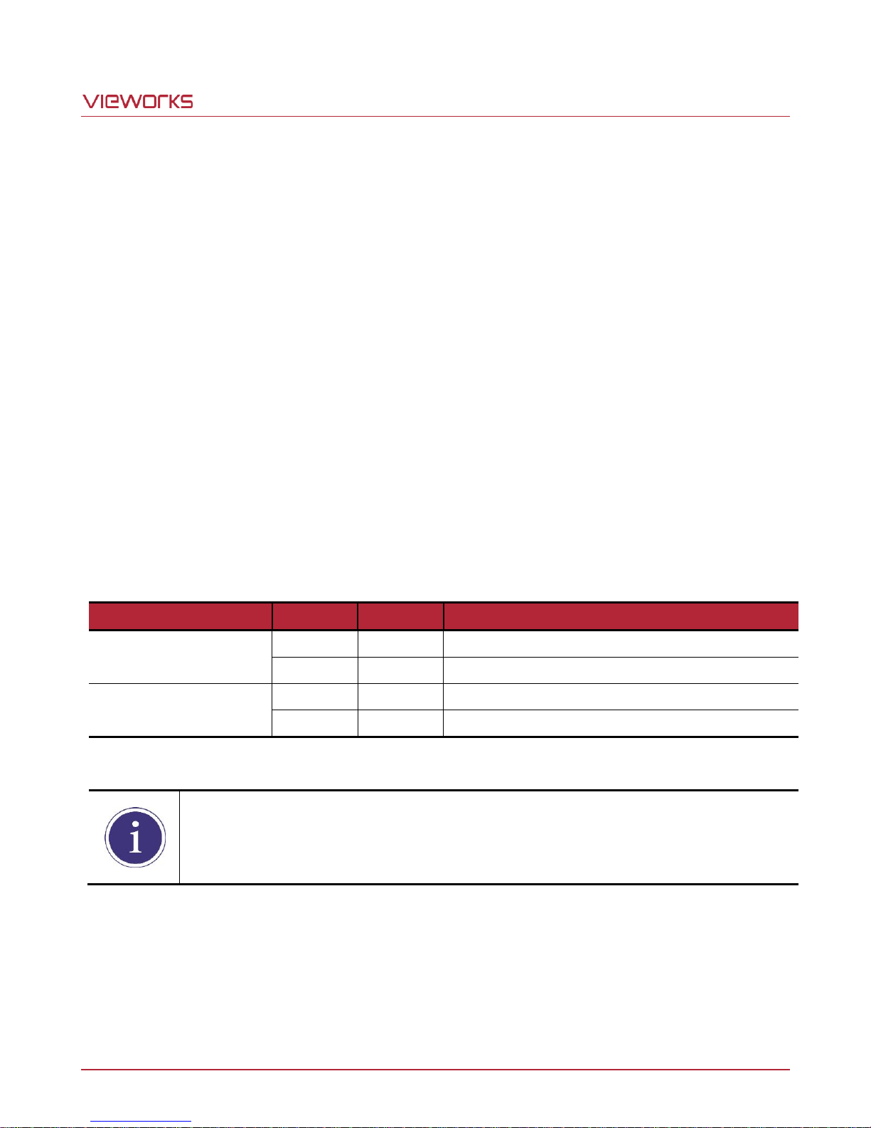
The Binning feature is only available on the VT-4K7C, VT-9K7C, VT-12K5C and VT-18K3.5C
cameras.
9.5 Binning
The binning feature has the effects of increasing the scan speed and decreasing resolution by summing the
values of the adjacent pixels and integrating them. This feature is particularly useful when you need to acquire
line images with lower resolution. With the Binning feature, you can acquire lower resolution images without
having to change the optics or lighting conditions.
Horizontal Binning
If the Binning Horizontal parameter is set to 2, the sensitivity of the imaging sensor will be increased and the
resolution of the imaging sensor will be decreased.
Vertical Binning
If the Binning Vertical parameter is set to 2, the camera can achieve faster scan speed and the resolution of
the imaging sensor will be decreased.
The commands related to the Binning feature are as follows.
Table 9.8 Commands related to Binning
Page 36 of 77 VW40-161-001
Page 37
VT Camera Link series
Configurator Parameter
Command
Value
Description
Data Bit
sdb 8
8 bit
Sets the data bit to 8 bit.
sdb 10
10 bit
Sets the data bit to 10 bit.
sdb 12
12 bit
Sets the data bit to 12 bit.
9.6 Data Bit
The camera processes image data in the unit of 12 bit internally. You can determine the format of these image
data transferred from the camera by using the Data Bit parameter.
Figure 9.3 Data Bit
The command related to the Data Bit is as follows.
Table 9.9 Command related to Data Bit
Page 37 of 77 VW40-161-001
Page 38
VT Camera Link series
Configurator Parameters
Command
Value
Description
Analog Gain
sag 1, 2, 3, 4
×1, ×2, ×3, ×4
Sets an absolute analog value (0 ~ 12 ㏈).
Digital Gain
sdg f
×1.0 ~ ×8.0
Sets an absolute digital gain value.
f: Float, 0 ~ 18 ㏈
Black Level
sdbl n
-255 ~ 255
Sets an absolute physical black level value.
n: Integer
9.7 Gain and Black Level
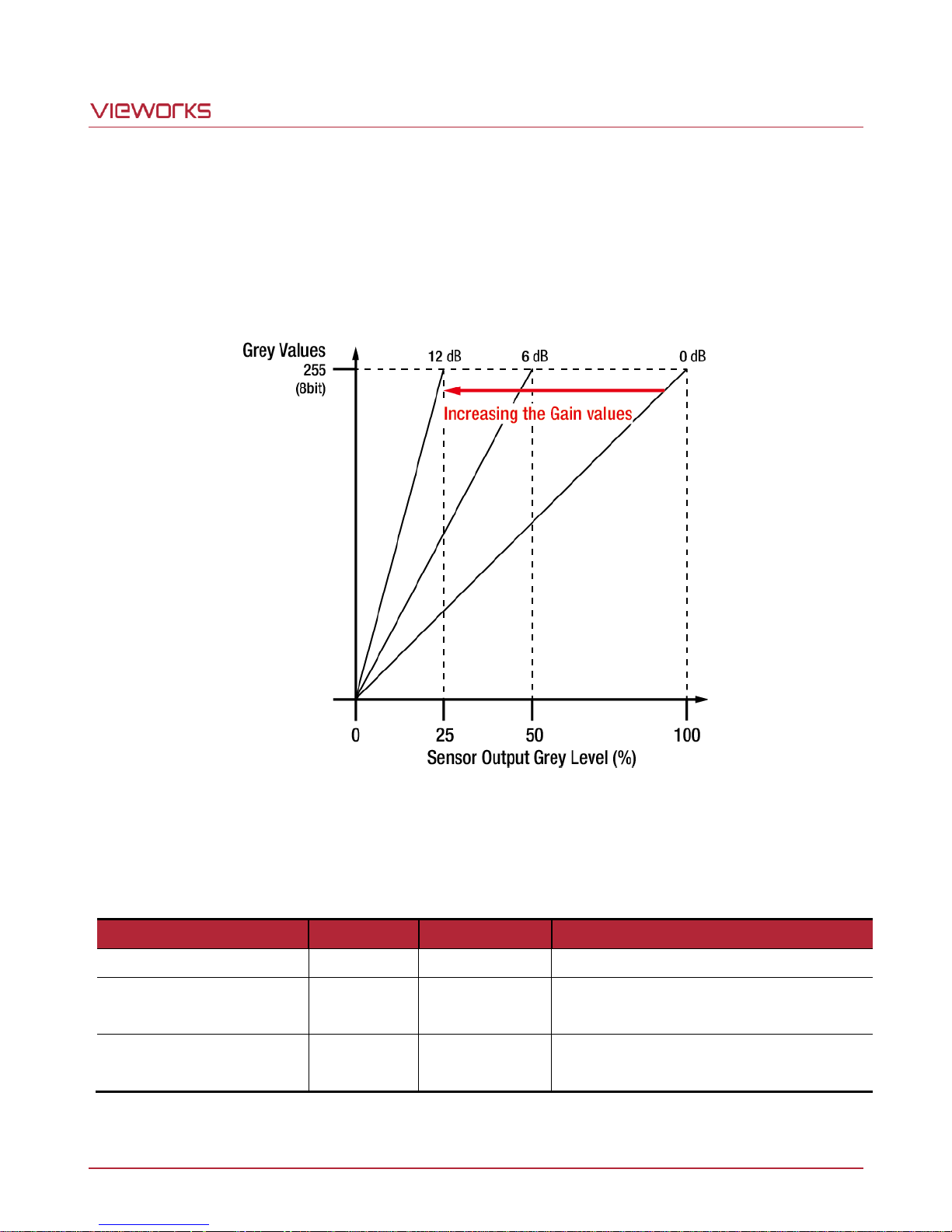
Increasing the Analog Gain parameter increases the slope of the camera’s response curve as shown in the
figure below. This results in a higher grey value output from the camera for a given amount of output from the
imaging sensor.
Adjusting the Black Level parameter will result in an offset to the pixel values output from the camera. The
commands related to the Gain and Black Level are as follows.
Table 9.10 Commands related to Gain and Black Level
Page 38 of 77 VW40-161-001
Figure 9.4 Setting the Analog Gain
Page 39
VT Camera Link series
Configurator Parameters
Command
Value
Description
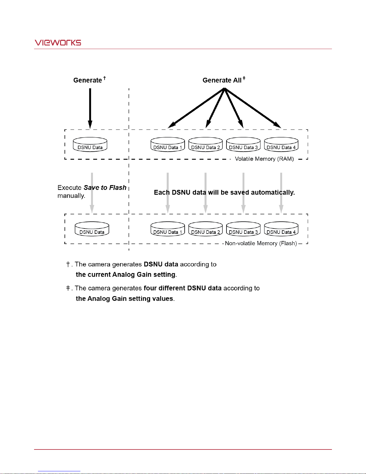
Generate All
gdda
-
Generates and saves the DSNU data for each Analog
Gain setting values (×1, ×2, ×3, ×4).
Generate
gdd - Generates the DSNU data.
Save to Flash
sdd - Saves the generated DSNU data in the non-volatile
memory.
The generated data by executing the Generate
parameter are saved in the volatile memory so that
the data lost if the camera is reset or if power is
turned off. To use the data after the camera is
powered on or reset, save them in the non-volatile
memory.
Load from Flash
ldd - Loads the DSNU data from the non-volatile memory into
the volatile memory.
9.8 Dark Signal Non-uniformity Correction
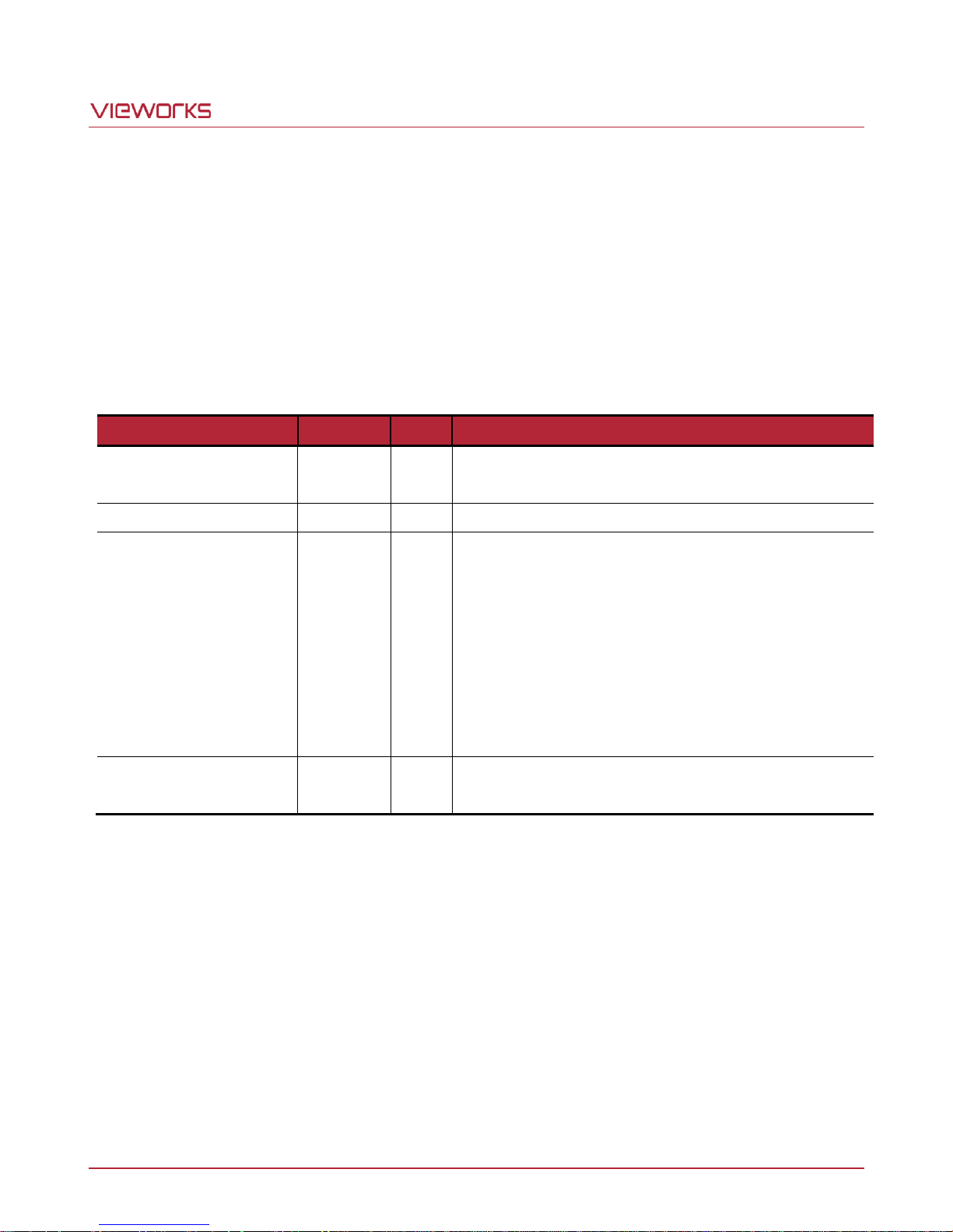
In theory, when a digital camera acquires images in complete darkness, all of the pixel values in the image
should be near zero and they should be equal. In practice, however, slight variations in the performance of the
pixels in the sensor will cause some variations in the pixel values output from the camera when the camera is
acquiring in darkness. This variation is known as Dark Signal Non-Uniformity (DSNU). The VT Camera Link
cameras provide the DSNU Correction feature.
The commands related to DSNU are as follows.
Table 9.11 Commands related to DSNU
Page 39 of 77 VW40-161-001
Page 40
VT Camera Link series
For optimum DSNU correction results, we recommend to generate DSNU data after the
temperature of the camera housing has been stabilized.
9.8.1 Generating and Saving User DSNU Correction Values
To generate and save user DSNU correction values, use the following procedure.
1. The camera will use the entire sensor when generating DSNU correction values. Therefore, we recommend
that you set the ROI setting to use the entire width of the sensor.
2. Ensure that the camera will be acquiring line images in complete darkness by covering the camera lens,
closing the iris in the lens, or darkening the room.
3. Begin acquiring line images either by setting the camera for the Free-Run mode or by supplying external
trigger signals to trigger line acquisitions.
4. Generate DSNU correction values.
Go to step 5 if you execute the Generate command to generate DSNU data.
Go to step 6 if you execute the Generate All command to generate DSNU data.
5. If you execute the Generate command,
a. Generates DSNU data according to the current Analog Gain setting value. The camera must acquire at
least 1024 line images to create a set of DSNU correction values.
b. After completing 1024 line acquisitions, the generated DSNU correction values will be activated and
saved in the camera’s volatile memory.
c. To save the generated DSNU correction values in the camera’s Flash (non-volatile) memory, execute the
Save to Flash command. The previous DSNU values for the current Analog Gain setting value saved in
the memory will be overwritten.
6. If you execute the Generate All command,
a. Generates the DSNU data for each Analog Gain setting values (×1, ×2, ×3, ×4) and then executes the
Save to Flash command automatically. The camera must acquire at least 4096 line images to create
sets of DSNU correction values.
b. After completing 4096 line acquisitions, the generated DSNU correction values according to the current
Analog Gain setting value will be activated.
7. If you change the Analog Gain setting value or want to load the existing values in the Flash memory,
execute the Load from Flash command.
Page 40 of 77 VW40-161-001
Page 41
VT Camera Link series
Figure 9.5 Generating and Saving DSNU Correction Values
Page 41 of 77 VW40-161-001
Page 42
VT Camera Link series
Configurator Parameters
Command
Value
Description
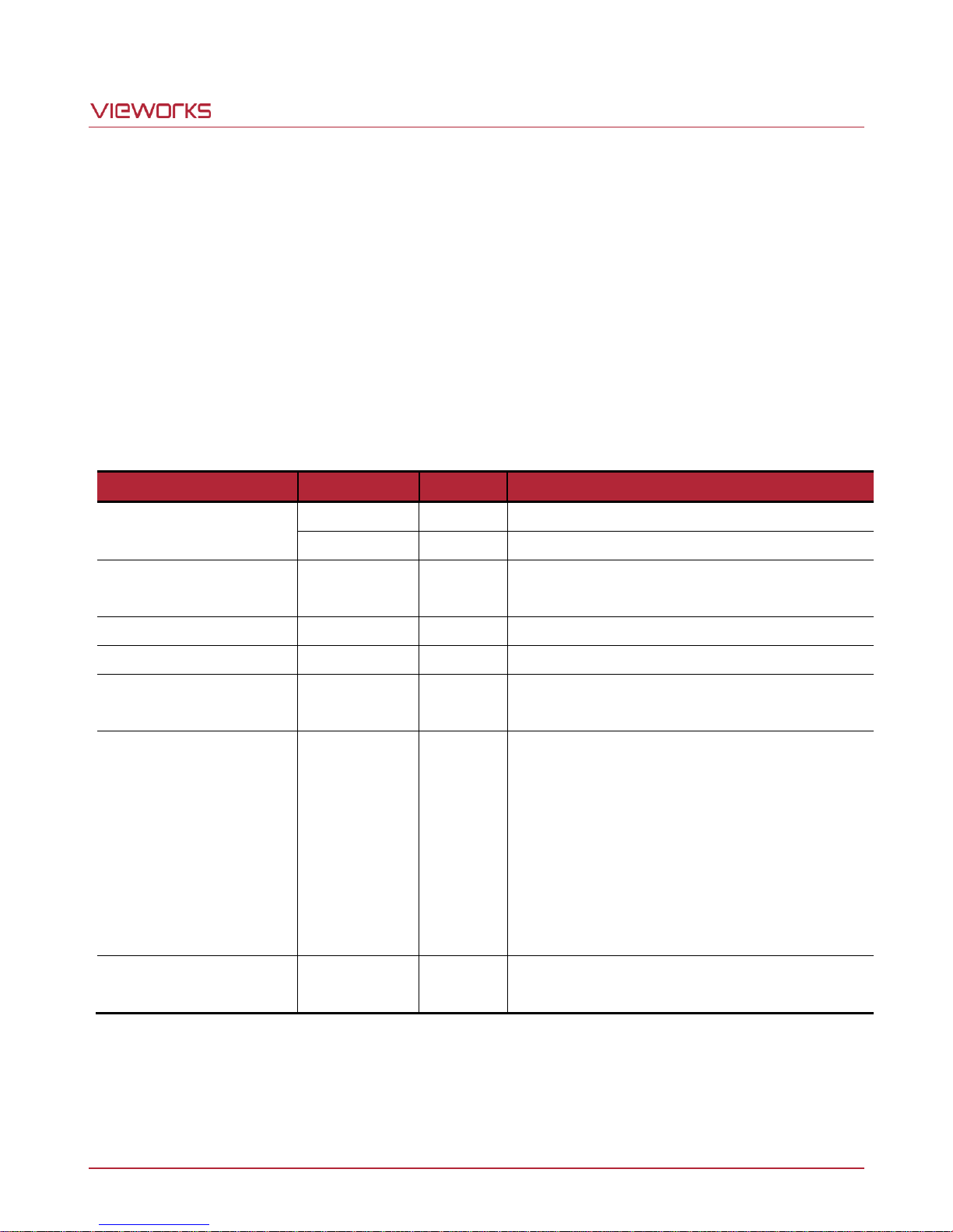
PRNU Correction
sprnu 0
Off
Disables the PRNU Correction feature.
sprnu 1
On
Enables the PRNU Correction feature.
PRNU Selector
spi 0, 1, 2, 3, 4
0/1/2/3/4
Selects a location to save PRNU data to or load
PRNU data from.
Auto
gpd 0
-
Select to set the PRNU Target Level automatically.
Target
-
1 ~ 255
Sets the PRNU Target Level.
Generate
gpd n
0 ~ 255
Generates the PRNU data.
0: Auto, 1 ~ 255: Sets the PRNU Target Level.
Save to Flash
spd
-
Saves the generated PRNU data in the nonvolatile memory.
The generated data by executing the
Generate command are saved in the volatile
memory so that the data are lost if the camera
is reset or if power is turned off. To use the
data after the camera is powered on or rest,
save them in the non-volatile memory.
Load from Flash
lpd
-
Loads the PRNU data from the non-volatile
memory into the volatile memory.
9.9 Photo Response Non-uniformity Correction
In theory, when a line scan camera acquires images with the camera viewing a uniform light-colored target in
bright light, all of the pixel values in the image should be near the maximum grey value and they should be
equal. In practice, however, slight variations in the performance of the pixels in the sensor, variations in the
optics, and variations in the lighting will cause some variations in the pixel values output from the camera. This
variation is known as Photo Response Non-uniformity (PRNU). The VT Camera Link cameras provide the PRNU
Correction feature and five storage locations for PRNU correction values.
The commands related to PRNU are as follows.
Page 42 of 77 VW40-161-001
Table 9.12 Commands related to PRNU
Page 43
VT Camera Link series
We strongly recommend that you generate new PRNU correction values whenever you
make a change to the optics or lighting or if you change the camera’s line rate.
For optimum PRNU correction results, we recommend to generate DSNU correction values
first before generating PRNU correction values.
9.9.1 Generating and Saving User PRNU Correction Values
To generate and save user PRNU correction values, use the following procedure.
1. The camera will use the entire sensor when generating PRNU correction values. Therefore, we recommend
that you set the ROI settings to use the entire width of the sensor.
2. Place a uniform white target in the field of view of the camera. Adjust the optics, lighting and line rates as
you would for normal operation. We recommend that you make adjustments to achieve the digital output
level in a range from 100 to 200 (Gain: 1.00 at 8 bit).
3. Begin acquiring line images either by setting the camera for the Free-Run mode or by supplying external
trigger signals to trigger line acquisition.
4. Set the Target Level.
To set the Target Level automatically, select the Auto check box.
To set the Target Level manually, deselect the Auto check box and input the target level in a range from
1 to 255 into the Target input box.
5. Execute the Generate command to generate PRNU correction values.
6. The camera must acquire at least 1024 line images to create a set of PRNU correction values.
7. After completing 1024 line acquisitions, the generated PRNU correction values will be activated and saved
in the camera’s volatile memory.
8. To save the generated PRNU correction values in the camera’s Flash (non-volatile) memory, specify a
location to save by using the PRNU Selector parameter and execute the Save to Flash command. The
existing values in the memory will be overwritten.
To ignore the generated PRNU correction values and load the existing values in the Flash memory, specify
a location to load from by using the PRNU Selector parameter and execute the Load from Flash
command.
Page 43 of 77 VW40-161-001
Page 44
VT Camera Link series
Configurator Parameters
Command
Value
Description
Reverse X
shf 0
-
Disables the Reverse X feature.
shf 1
-
Enables the Reverse X feature.
9.10 Reverse X
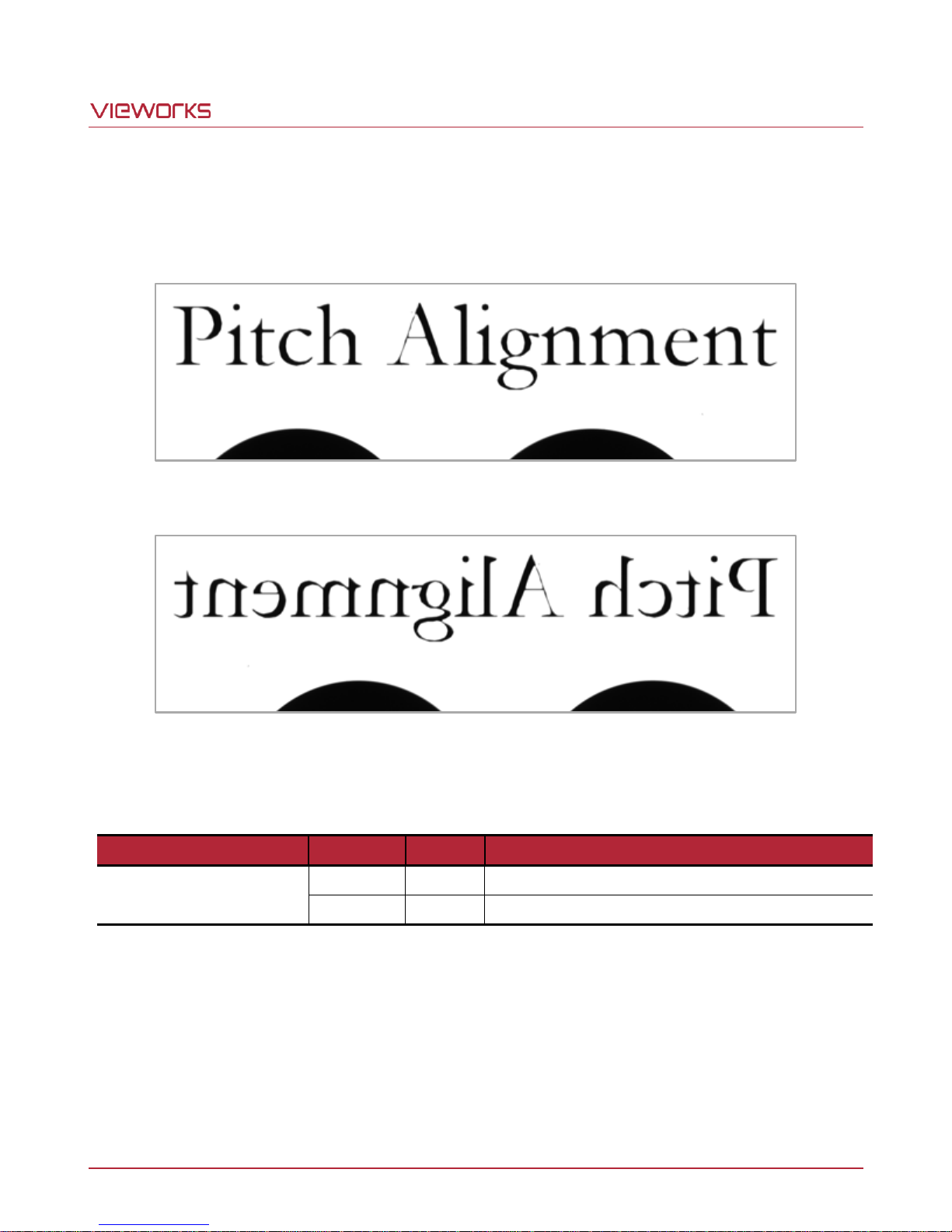
The Reverse X feature lets you flip the image horizontally. This feature is available in all operation modes.
Figure 9.6 Original Image
Figure 9.7 Reverse X Image
The commands related to Reverse X is as follows.
Table 9.13 Commands related to Reverse X
Page 44 of 77 VW40-161-001
Page 45
VT Camera Link series
Configurator Parameters
Command
Value
Description
Tap Mode
scl 0
2 Tap
Sets the Camera Link Output Mode to 2 Tap.
scl 1
4 Tap
Sets the Camera Link Output Mode to 4 Tap.
scl 2
8 Tap
Sets the Camera Link Output Mode to 8 Tap.
scl 3
10 Tap
Sets the Camera Link Output Mode to 10 Tap.
9.11 Camera Link Output
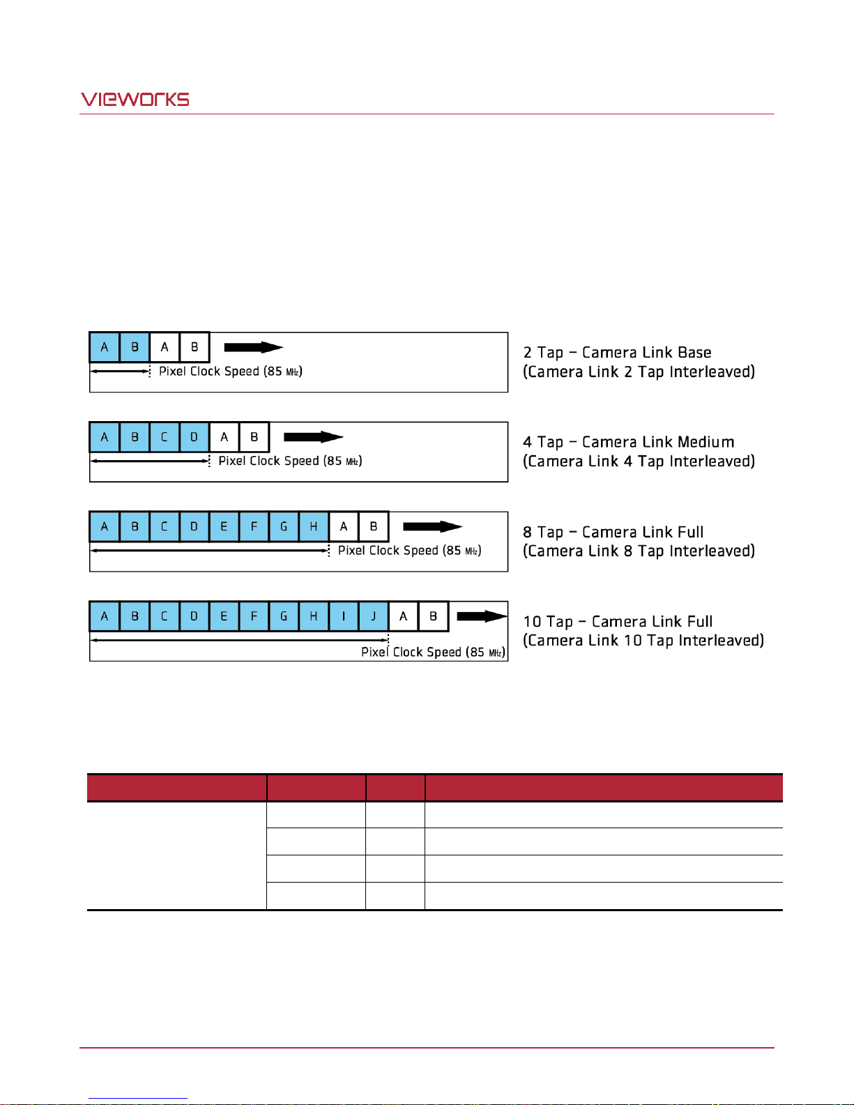
The VT Camera Link cameras supports 2 Tap, 4 Tap, 8 Tap and 10 Tap Camera Link output modes. The number
of taps represents the number of pixel data that will be output on each cycle of the Camera Link pixel clock. The
maximum allowed line rate will be changed according to the Tap Mode settings. The line image data is
transmitted in the interleaved order as shown in the figure below.
Figure 9.8 Camera Link Output Mode
The commands related to Camera Link Output Mode are as follows.
Table 9.14 Commands related to Camera Link Output Mode
Page 45 of 77 VW40-161-001
Page 46
VT Camera Link series
Configurator Parameters
Command
Value
Description
Strobe Mode
ssm 0
Off
Disables the Strobe Mode feature.
ssm 1
Timed
Outputs pulse signals according to the Strobe
Duration setting values.
-
ssm 2
Pulse Width
Outputs pulse signals of which the period is
equal to the trigger signals applied to the
camera.
Strobe Inverter
ssp 0
-
Deselect not to invert the output signal.
ssp 1
-
Select to invert the output signal.
Strobe Duration
ssr f
1.00 ~ 1000.00
Sets a period of the pulse signal in
microseconds when the Strobe Mode is set to
Timed.
Strobe Delay
sto f
0.00 ~ 1000.00
Sets a delay to the current output signal in
microseconds.
9.12 Strobe Mode
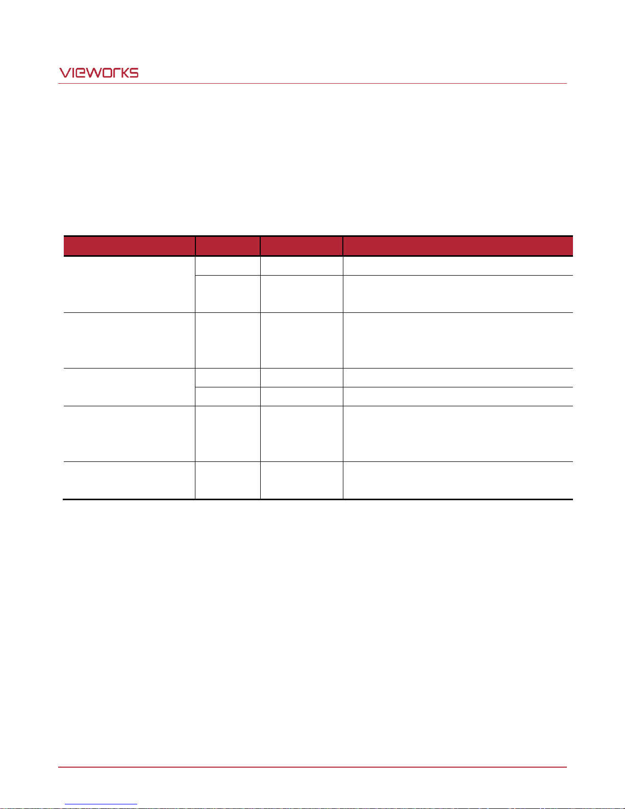
The VT Camera Link cameras can output pulse signals through the control I/O receptacle. You can set a period
of the pulse signal by using the Strobe Mode parameter. This feature is useful when you need to supply source
signals to the other devices such as a Strobe Controller.
The commands related to Strobe Mode are as follows.
Table 9.15 Commands related to Strobe Mode
Page 46 of 77 VW40-161-001
Page 47
VT Camera Link series
Command
Description
gct
Displays device temperature in Celsius.
Status LED
Descriptions
Steady Red
Camera is not initialized.
Steady Green
Camera is waiting for transmitting images.
Fast Flashing Green
Camera is acquiring images.
9.13 Temperature Monitor
The camera has an embedded sensor chip to monitor the internal temperature.
The command related to the device temperature is as follows.
Table 9.16 Command related to Device Temperature
9.14 Status LED
A red/green LED is installed on the back panel of the camera to inform the operation status of the camera. LED
status and corresponding camera status are as follows.
Table 9.17 Status LED
Page 47 of 77 VW40-161-001
Page 48
VT Camera Link series
Configurator Parameters
Command
Value
Description
Test Image
sti 0
Off
Disables the Test Image feature.
sti 1
Test #1
Sets the Test Image to Test #1.
sti 2
Test #2
Sets the Test Image to Test #2.
sti 3
Test #3
Sets the Test Image to Test #3.
9.15 Test Image
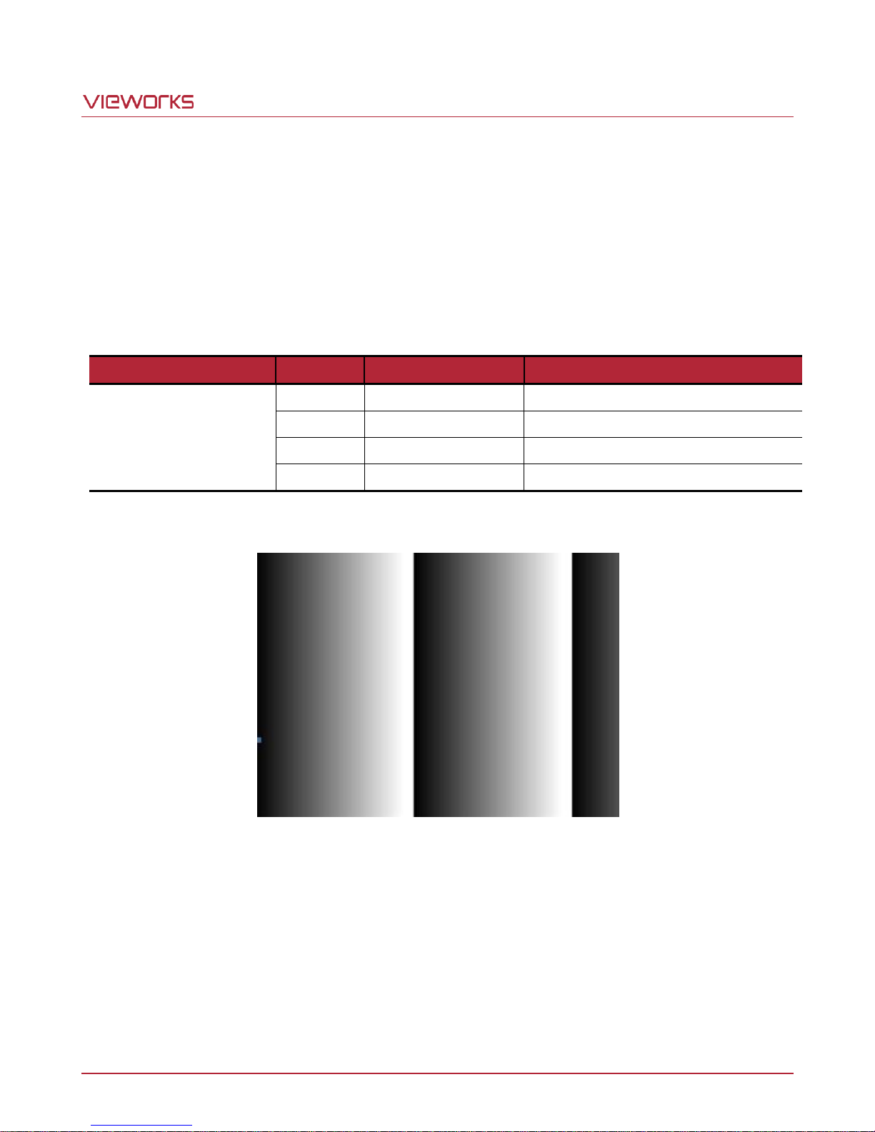
To check normal operation of the camera, it can be set to output test images created inside, instead of image
data from the imaging sensor. There are three types of test images; image with different value in horizontal
direction (Test #1), image with different value in diagonal direction (Test #2), and moving image with different
value in diagonal direction (Test #3).
The commands related to Test Image are as follows.
Table 9.18 Command related to Test Image
Figure 9.9 Test #1
Page 48 of 77 VW40-161-001
Page 49
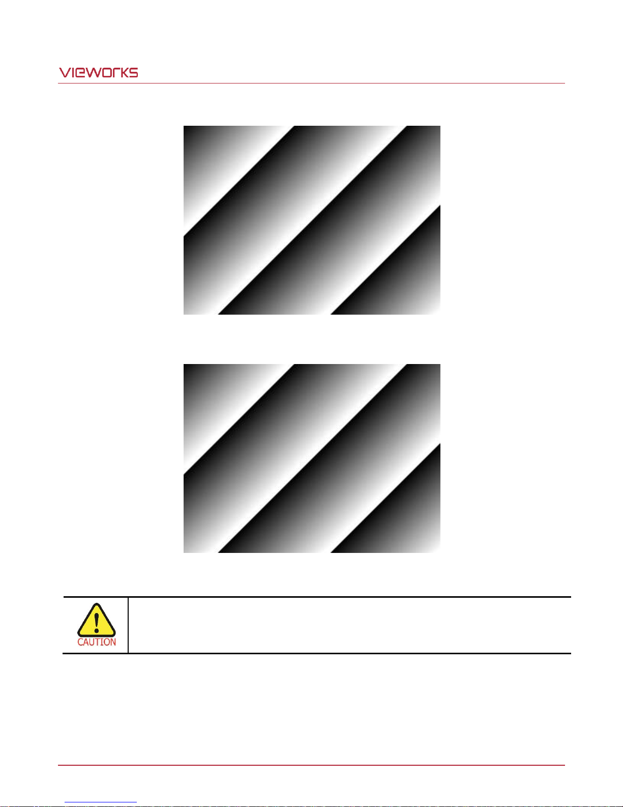
VT Camera Link series
The test image may look different because the region of the test image may vary depending on
the camera’s resolution.
Figure 9.10 Test #2
Figure 9.11 Test #3
Page 49 of 77 VW40-161-001
Page 50
VT Camera Link series
Configurator Parameters
Command
Value
Description
Pre-emphasis
spe 0
Off
Disables the Pre-emphasis feature.
spe 1
On
Enables the Pre-emphasis feature.
9.16 Pre-emphasis
The Pre-emphasis feature provided by the VT Camera Link cameras increases the available Camera Link cable
length up to 10 meters.
The commands related to Pre-emphasis are as follows.
Table 9.19 Command related to Pre-emphasis
9.17 Field Upgrade
The camera provides a feature to upgrade Firmware and FPGA logic through the Camera Link interface rather
than disassemble the camera in the field. Refer to Appendix A for more details on how to upgrade.
Page 50 of 77 VW40-161-001
Page 51
VT Camera Link series
10 Camera Configuration
10.1 Setting Commands
You can configure all camera settings via RS-644 serial interface of the Camera Link. When you want to control
the camera using a terminal or to access directly to the camera at your application, you need to set your network
as follows.
Baud Rate: 115200 bps
Data Bit: 8 bit
Parity Bit: No Parity
Stop Bit: 1 stop bit
Flow Control: None
All camera setting commands are transmitted in the ASCII command type except a command for transmitting a
large file such as firmware download. All camera setting commands are transmitted from the user application
and then the camera returns a response (“OK”, “Error” or information) for a command. When you execute a write
command, the camera returns a response to inform whether the command has been successfully executed.
When you execute a read command, the camera returns an error or information.
Command Format:
<command> <parameter1> <parameter2> <cr>
0 – 2 parameters follow the command.
Response:
If a write command is successfully executed
OK <cr> <lf>
ex) Write Command
In response to a “set 100” command the camera will return (in hex value)
Command: 73 65 74 20 31 30 30 0D
set 100<cr>
Response: 73 65 74 20 31 30 30 0D 0A 4F 4B 0D 0A 3E
set 100<cr><lf> OK<cr><lf> >
Echo result prompt
Page 51 of 77 VW40-161-001
Page 52
VT Camera Link series
If a read command is successfully executed
<parameter1> <cr> <lf>
ex) Read Command
In response to a “get” command the camera will return (in hex value)
Command: 67 65 74 0D
get <cr>
Response: 67 65 74 0D 0A 31 30 30 0D 0A 3E
get<cr><lf> 100<cr><lf> >
Echo response prompt
If a command is not executed successfully
Error: <Error Code> <cr> <lf>
Prompt:
A prompt always follows after the response. ‘>’ is used as prompt.
Types of Error Code
0x80000481: value of parameter is not valid
0x80000482: the number of parameter is not matched
0x80000484: command does not exeist
0x80000486: no permission to execute
Page 52 of 77 VW40-161-001
Page 53
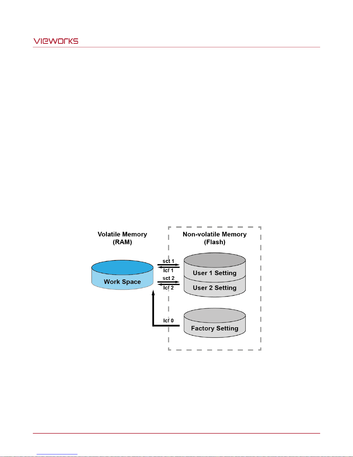
VT Camera Link series
10.2 User Set Control
The VT Camera Link cameras provide three non-volatile spaces (Flash) for storing parameter settings and one
work space (RAM) for operating the camera. Non-volatile spaces are divided into a Factory space (Factory
Setting) that contains default setting values entered during the manufacturing, and two User spaces (User 1
Setting and User 2 Setting) that are available for saving user-defined setting values.
You can save the current camera settings to a user space or you can load the settings stored in one of the non-
volatile spaces into the camera’s work space. The default setting values stored in the factory space can be
loaded into the camera’s work space, but cannot be changed.
The setting values in the camera’s volatile memory will be lost if the camera is reset or powered off.
To use the current setting values in the work space after a reset, you must save the settings to one of the user
spaces.
By default, the Factory Setting will be loaded into the camera when the camera is reset or powered on. You can
change the Configuration Initialization value to select which setting values will be loaded when the camera is
reset or powered on.
Figure 10.1 User Set Control
Page 53 of 77 VW40-161-001
Page 54
VT Camera Link series
Configurator Parameters
Command
Value
Description
Load Setting
lcf 0
Factory Space
Loads the Factory Default Settings to the
camera.
lcf 1
User 1 Space
Loads the User 1 Settings to the camera.
lcf 2
User 2 Space
Loads the User 2 Settings to the camera.
Save Setting
sct 1
User 1 Space
Saves the current settings to the User 1 Setting.
sct 2
User 2 Space
Saves the current settings to the User 2 Setting.
Start-Up
sci 0
Factory Setting
Applies the Factory Default Settings when reset.
sci 1
User 1 Setting
Applies the User 1 Settings when reset.
sci 2
User 2 Setting
Applies the User 2 Settings when reset.
Configurator Parameters
Value
Operation Mode
TDI
Direction
Forward
TDI Stages
Maximum Integration Stages
Trigger Mode
Off
Test Image
None
Binning
1
Data Bit
8
PRNU Correction
On
Tap Mode
8 Tap
Analog Gain
1
Digital Gain
1
Line Rate
35 ㎑
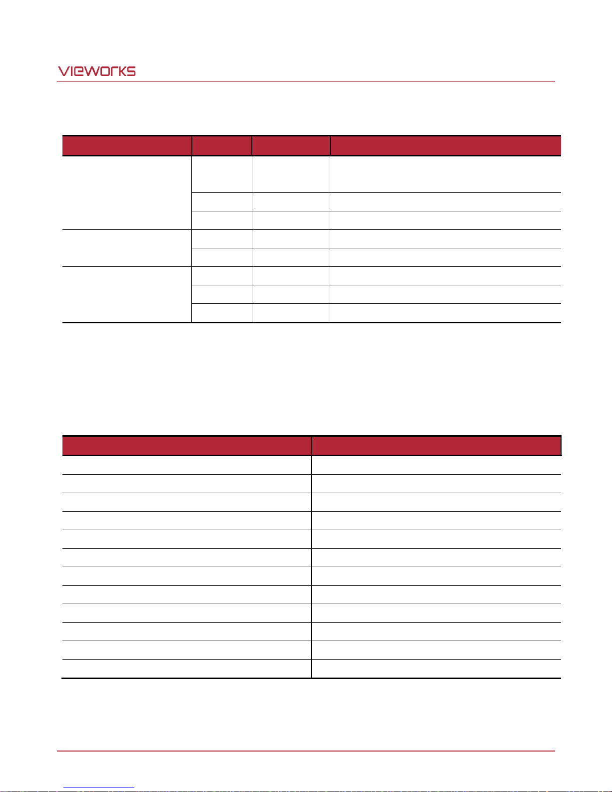
The commands related to User Set are as follows.
Table 10.1 Commands related to User Set Control
10.2.1 Factory Default Setting Values
When you power the VT Camera Link camera for the first time on, the factory default setting values will be
loaded into the camera and the factory default setting values are as follows.
Table 10.2 Factory Default Setting Values
Page 54 of 77 VW40-161-001
Page 55
VT Camera Link series
Command Syntax
Return Value
Description
Help
h
String
Displays a list of all commands.
Set Offset X
Get Offset X
sox n
gox
OK n X coordinate of start point ROI
n: X axis offset
Set Image Width
Get Image Width
siw n
giw
OK
n
Width of ROI, n: Width value
VT-4K: 256 ~ 4096
VT-9K: 256 ~ 8912
VT-12K: 256 ~ 12480
VT-18K: 256 ~ 17824
Set Binning Horizontal
Get Binning Horizontal
sbh 1|2
gbh
OK
1|2
Sets the horizontal binning.
1: 1 binning horizontal (No binning)
2: 2 binning horizontal
Set Binning Vertical
Get Binning Vertical
sbv 1|2
gbv
OK
1|2
Sets the vertical binning.
1: 1 binning vertical (No binning)
2: 2 binning vertical
Set Test Image
Get Test Image
sti 0|1|2|3
gti
OK
0|1|2|3
Sets the Test Image.
0: Test Image Off
1, 2: Fixed pattern image
3: Moving pattern image
Set Scan Direction
Get Scan Direction
ssd 0|1|2
gsd
OK
0|1|2
Sets the camera’ scan direction.
0: Forward
1: Reverse
2: Line 1 (External Port)
Set Data Bit
Get Data Bit
sdb 8|10|12
gdb
OK
8|10|12
Sets the camera’s data bit.
8: 8 bit output
10: 10 bit output
12: 12 bit output
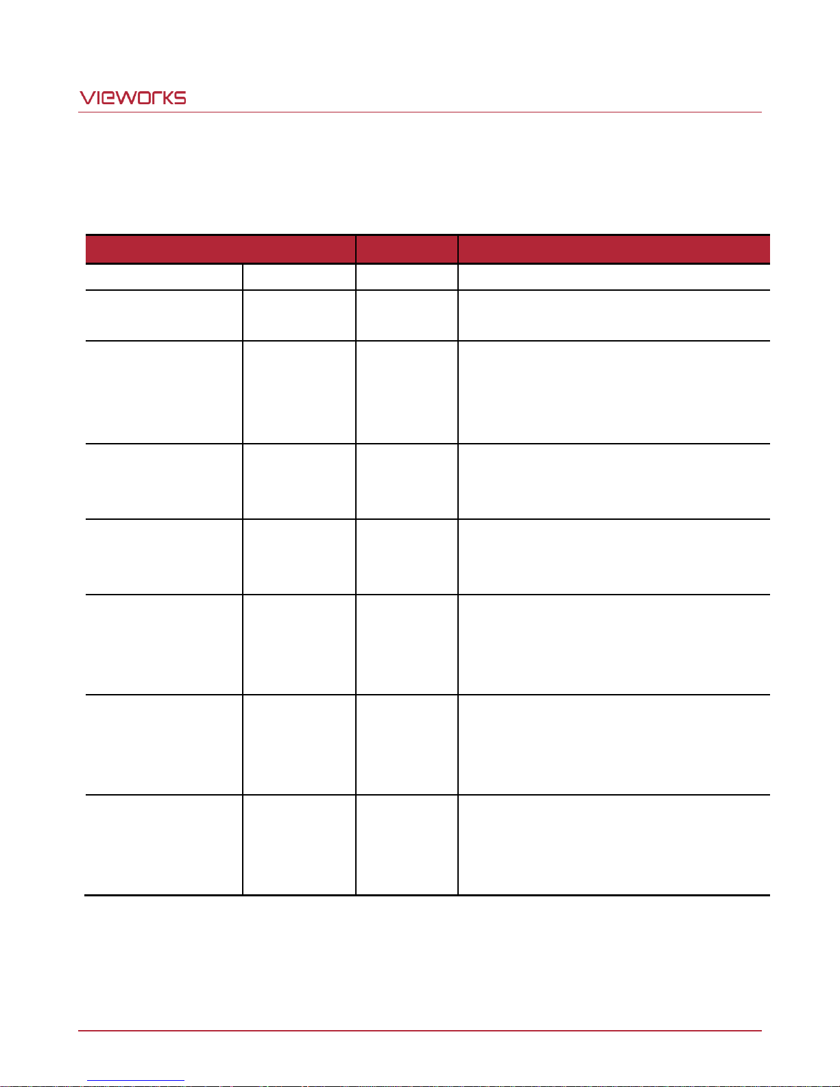
10.3 Command List
You can set all features provided by the VT Camera Link camera by using the following commands.
Page 55 of 77 VW40-161-001
Table 10.3 Command List #1
Page 56
VT Camera Link series
Command Syntax
Return Value
Description
Set TDI Stage
Get TDI Stage
std 1|2|3|4
gtd
OK
1|2|3|4
Sets the number of TDI Stage.
1: 16 Stage
2: 32 Stage
3: 48 Stage
4: 64 Stage
VT-4K14C
Set TDI Stage
Get TDI Stage
std 1|2|3|4
gtd
OK
1|2|3|4
1: 32 Stage
2: 64 Stage
3: 96 Stage
4: 128 Stage
VT-4K7C
VT-9K7C
Set TDI Stage
Get TDI Stage
std 1|2|3|4
gtd
OK
1|2|3|4
1: 64 Stage
2: 128 Stage
3: 192 Stage
4: 256 Stage
VT-12K5C
VT-18K3.5C
Set Line Rate
Get Line Rate
slr f
glr
OK f Sets the camera’s line rate.
f: Line period (㎲) <Float>
Set Exposure Time
Get Exposure Time
set n
get
OK
n
Sets an exposure time (When the Operation
Mode is set to Area)
n: exposure time in microseconds (㎲)
Set Trigger Mode
Get Trigger Mode
stm 0|1
gtm
OK
0|1
Sets the Trigger Mode.
0: Free-Run mode
1: Activates the Trigger Mode.
Set Horizontal Flip
Get Horizontal Flip
shf 0|1
ghf
OK
0|1
Enables the Reverse X feature.
0: Disables the Reverse X feature.
1: Enables the Reverse X feature.
Set Trigger Source
Get Trigger Source
sts 1|5
gts
OK
1|5
Specifies a source signal when the Trigger
Mode is set to On.
1: CC1 port (Camera Link)
5: External port (Line 1)
Set Trigger Activation
Get Trigger Activation
sta 0|1|2
gta
OK
0|1|2
Specifies a polarity of trigger when the Trigger
Mode is set to On.
0: Rising
1: Falling
2: Both
Page 56 of 77 VW40-161-001
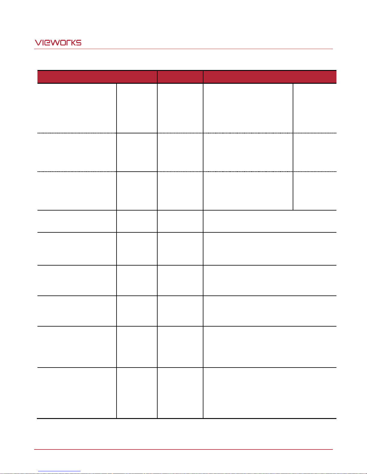
Table 10.4 Command List #2
Page 57
VT Camera Link series
Command Syntax
Return Value
Description
Set Trigger Rescaler Mode
Get Trigger Rescaler Mode
srm 0|1
grm
OK
0|1
Enables the Trigger Rescaler feature.
0: Disables the Trigger Rescaler feature.
1: Enables the Trigger Rescaler feature.
Set Trigger Rescaler Rate
Get Trigger Rescaler Rate
srr f
grr
OK
f
Sets the trigger rescaler rate.
f: Rescaler rate <Float>
(Setting range: 0.010 ~ 100.000)
Set Trigger Rescaler Filter
Get Trigger Rescaler Filter
srf 0|1|2|3|4|5
grf
OK
0|1|2|3|4|5
Sets the Trigger Rescaler Noise Filter.
0: 16 1: 32
2: 64 3: 128
4: 256 5: 512
Set Operation Mode
Get Operation Mode
som 0|1
gom
OK
0|1
Sets the camera’s operation mode.
0: TDI mode
1: Area mode
Set Strobe Mode
Get Strobe Mode
ssm 0|1|2
gsm
OK
0|1|2
Sets whether to output strobe signals.
0: Off
1: Outputs strobe signals according to the
Strobe Duration setting value.
2: Outputs signals of which the period is
equal to the trigger signals applied to the
camera.
Set Strobe Inverter
Get Strobe Inverter
ssp 0|1
gsp
OK
0|1
Sets whether to invert strobe signals.
0: Disables the inversion of strobe signals.
1: Enables the inversion of strobe signals.
Set Strobe Delay
Get Strobe Delay
sto f
gto
OK
f
Sets a delay to the strobe signal.
f: Strobe delay (㎲) <Float>
(Setting range: 0.00 ~ 1000.00 ㎲)
Set Strobe Duration
Get Strobe Duration
ssr f
gsr
OK
f
Sets a period of the strobe signal in
microseconds when the Strobe Mode is set
with the ssm 1 command.
f: Strobe duration (㎲) <Float>
(Setting range: 1.00 ~ 1000.00 ㎲)
Page 57 of 77 VW40-161-001
Table 10.5 Command List #3
Page 58
VT Camera Link series
Command Syntax
Return Value
Description
Set Analog Gain
Get Analog Gain
sag 1|2|3|4
gag
OK
1|2|3|4
Sets the Analog Gain.
1/2/3/4: Analog gain (1, 2, 3, 4)
Set Digital Gain
Get Digital Gain
sdg f
gdg
OK
f
Sets the Digital Gain.
f: Digital gain <Float>
(Setting Range: 1.000 ~ 8.000)
Set Black Level
Get Black Level
sdbl n
gdbl
OK n Sets the Black Level.
n: Black level (Setting Range: -255 ~ 255)
Generate DSNU Data All
gdda
OK
Generates and saves the DSNU data for each
Analog Gain setting values.
Generate DSNU Data
gdd
OK
Generates the DSNU data for the current
Analog Gain setting value.
Save DSNU Data
sdd
OK
Saves the generated DSNU data in the nonvolatile memory.
Load DSNU Data
ldd
OK
Loads the DSNU data from the non-volatile
memory into the volatile memory.
Set DSNU Transform
sdt n1 (n2) v1
OK
Performs additional correction to the PRNU
correction values.
n1: X coordinate of a start pixel
n2: X coordinate of an end pixel
v1: Black level value to be added to the
specified region (-255 ~ 255)
Set DSNU Coefficient
Get DSNU Coefficient
sdc n f1
gdc n1 (n2)
OK
f1
Sets or retrieves the DSNU Correction
Coefficient.
n: X coordinate of a pixel to set
n1: X coordinate of a start pixel
n2: X coordinate of an end pixel
f1: DSNU correction coefficient
(Black Level = 0.1 ~ 4095)
Page 58 of 77 VW40-161-001
Table 10.6 Command List #4
Page 59
VT Camera Link series
Command Syntax
Return Value
Description
Generate PRNU Data
gpd n
OK
Generates the PRNU data.
n: Target level
(Setting Range: 1 ~ 255, 0: Auto)
Set PRNU Mode
Get PRNU Mode
sprnu 0|1
gprnu
OK
0|1
Sets the PRNU Correction feature.
0: Disables the PRNU Correction feature.
1: Enables the PRNU Correction feature.
Save PRNU Data
spd
OK
Saves the PRNU data in the non-volatile
memory.
Load PRNU Data
lpd
OK
Loads the PRNU data from the non-volatile
memory into the volatile memory.
PRNU Selector
spi 0|1|2|3|4
gpi
OK
0|1|2|3|4
Selects a location to save PRNU data to or
load PRNU data from.
0/1/2/3/4: PRNU data storage area
Set PRNU Transform
spt n1 (n2) f1
OK
Performs additional correction to the PRNU
correction values.
n1: X coordinate of a start pixel
n2: X coordinate of an end pixel
f1: Gain value to be multiplied to the specified
region (0.1 ~10.0).
Set PRNU Coefficient
Get PRNU Coefficient
spc n f1
gpc n1 n2
OK
f1
Sets or retrieves the PRNU Correction
Coefficient.
n: X coordinate of a pixel to set
n1: X coordinate of a start pixel
n2: X coordinate of an end pixel
f1: PRNU correction coefficient
(Gain = 0.1 ~10.0)
Set Camera Link mode
Get Camera Link mode
scl 0|1|2|3
gcl
OK
0|1|2|3
Sets the Camera Link Output mode.
0: 2 Tap
1: 4 Tap
2: 8 Tap
3: 10 Tap
Set Pre-emphasis mode
Get Pre-emphasis mode
spe 0|1
gpe
OK
0|1
Sets the Pre-emphasis feature.
0: Disables the Pre-emphasis feature.
1: Enables the Pre-emphasis feature.
Page 59 of 77 VW40-161-001
Table 10.7 Command List #5
Page 60
VT Camera Link series
Command Syntax
Return Value
Description
Load Config From
lcf 0|1|2
OK
Loads camera setting values to the camera’s
work space.
0: Loads from Factory space.
1: Loads from User 1 space.
2: Loads from User 2 space.
Save Config To
sct 1|2
OK
Saves the current camera setting values.
1: Saves to User 1 space.
2: Saves to User 2 space.
Set Config Initialization
Get Config Initialization
sci 0|1|2
gci
OK
0|1|2
Specifies setting values to be loaded when
reset.
0: Applies Factory default settings when reset.
1: Applies User 1 settings when reset.
2: Applies User 2 settings when reset.
Get MCU Version
gmv
String
Displays the version of camera MCU.
Get Model Number
gmn
String
Displays camera model name.
Get FPGA Version
gfv
String
Displays the version of camera FPGA.
Get Serial Number
gsn piece
String
Displays the serial number of the camera.
Get Current Temperature
gct
String
Displays device temperature in Celsius.
Reset
rst - Resets the camera.
Page 60 of 77 VW40-161-001
Table 10.8 Command List #6
Page 61
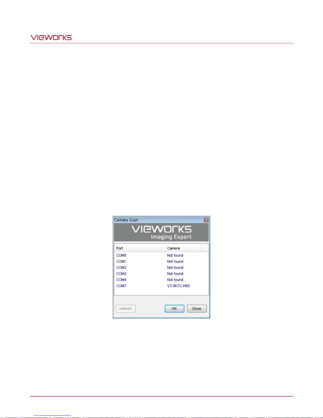
VT Camera Link series
11 Configurator GUI
Configurator, a sample application, is provided to control the VT Camera Link cameras. Configurator provides
easy-to-use Graphic User Interface (GUI) that allows users to view and change the camera’s settings mentioned
in the previous chapters.
11.1 Camera Scan
When you execute the Configurator.exe file while the camera is powered on, the Camera Scan window appears
as shown in the figure below. At this time, the Configurator checks serial ports of your computer and DLL
provided by the Camera Link to scan whether a camera is connected. If the Configurator finds a connected
camera, it displays the model name of the camera on the Camera Scan window. If the camera is not displayed
on the window, check the cable connections and power of the camera, and then press the refresh button.
Double-clicking the model name of the camera displayed on the window will launch the Configurator and display
the current parameter settings of the camera connected.
Figure 11.1 Configurator Loading Window
Page 61 of 77 VW40-161-001
Page 62
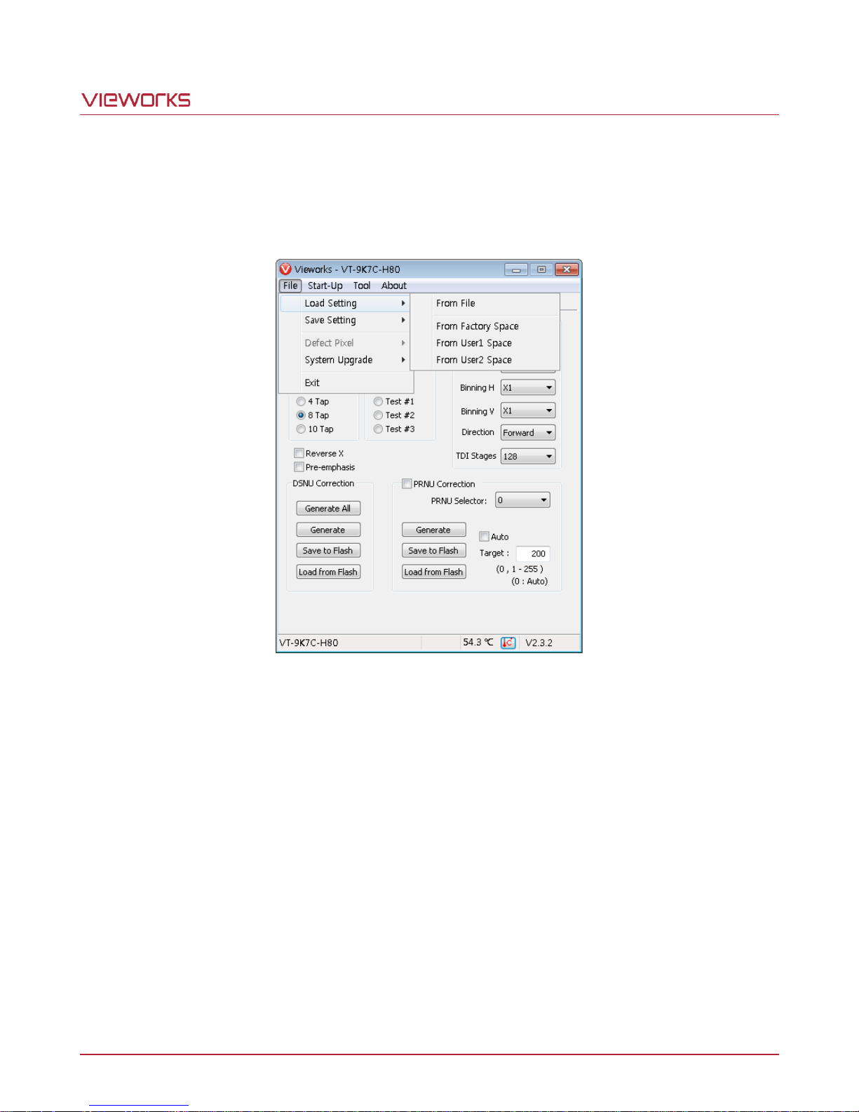
VT Camera Link series
11.2 Menu
11.2.1 File
Figure 11.2 File Menu
Load Setting: Loads the camera setting values from the camera memory (Factory, User1 or
User2) or user’s computer (From File).
Save Setting: Saves the camera setting values to the camera memory (User1 or User2) or user’s
computer (To File).
System Upgrade: Upgrades MCU or FPGA logic.
Exit: Exits the Configurator.
Page 62 of 77 VW40-161-001
Page 63
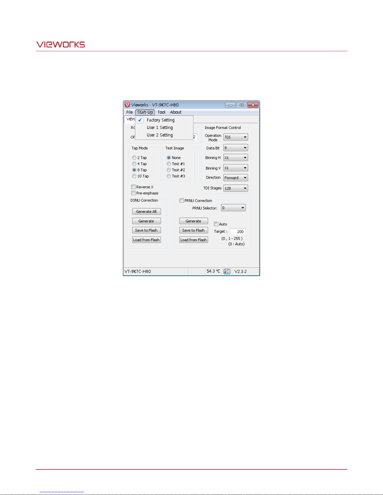
VT Camera Link series
11.2.2 Start-Up
You can select the camera setting values to load when the camera is powered on.
Figure 11.3 Start-Up Menu
Factory Setting: Loads the camera setting values from Factory Space when the camera is powered on.
User1 Setting: Loads the camera setting values from User1 Space when the camera is powered on.
User2 Setting: Loads the camera setting values from User2 Space when the camera is powered on.
Page 63 of 77 VW40-161-001
Page 64
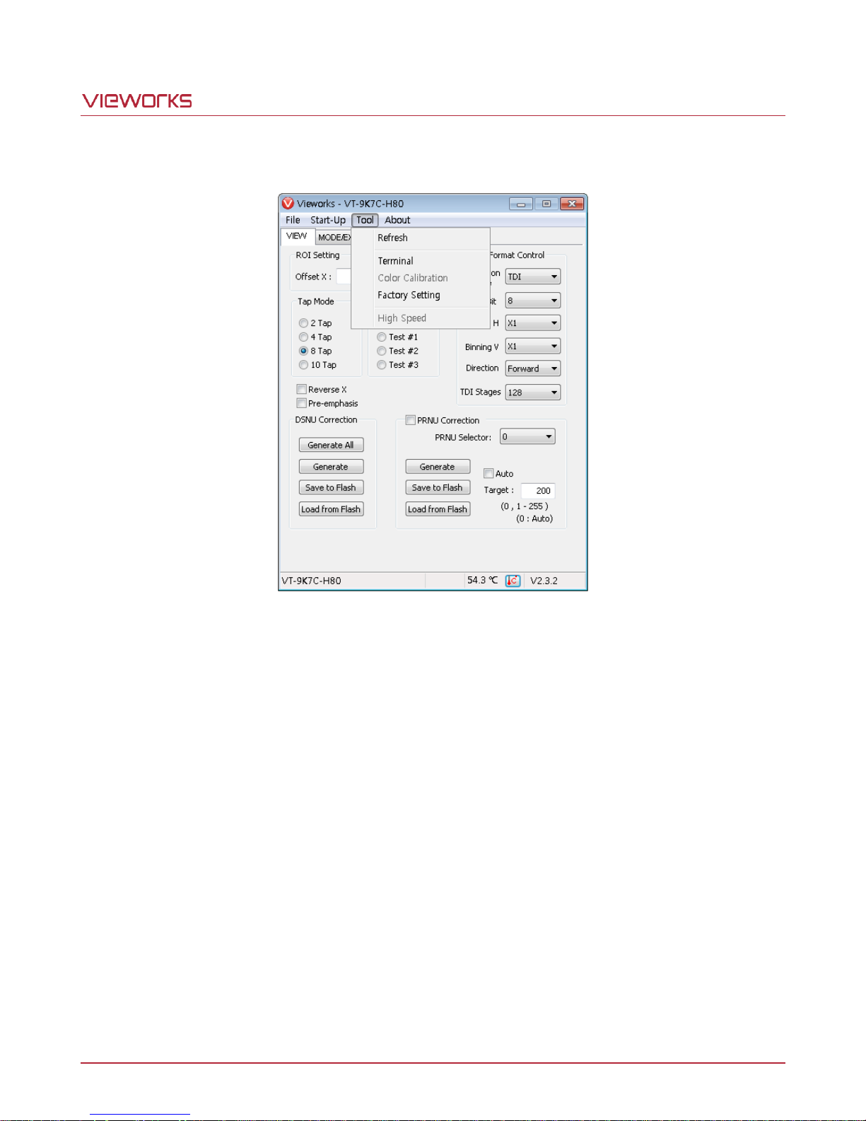
VT Camera Link series
11.2.3 Tool
Figure 11.4 Tool Menu
Refresh: Loads and displays the current camera setting values on Configurator.
Terminal: Displays user commands in the Terminal window under the GUI.
To hide the Terminal window, uncheck Terminal by clicking again.
Factory Setting: Not supported for users.
High Speed: Not supported on the VT Camera Link cameras.
Page 64 of 77 VW40-161-001
Page 65
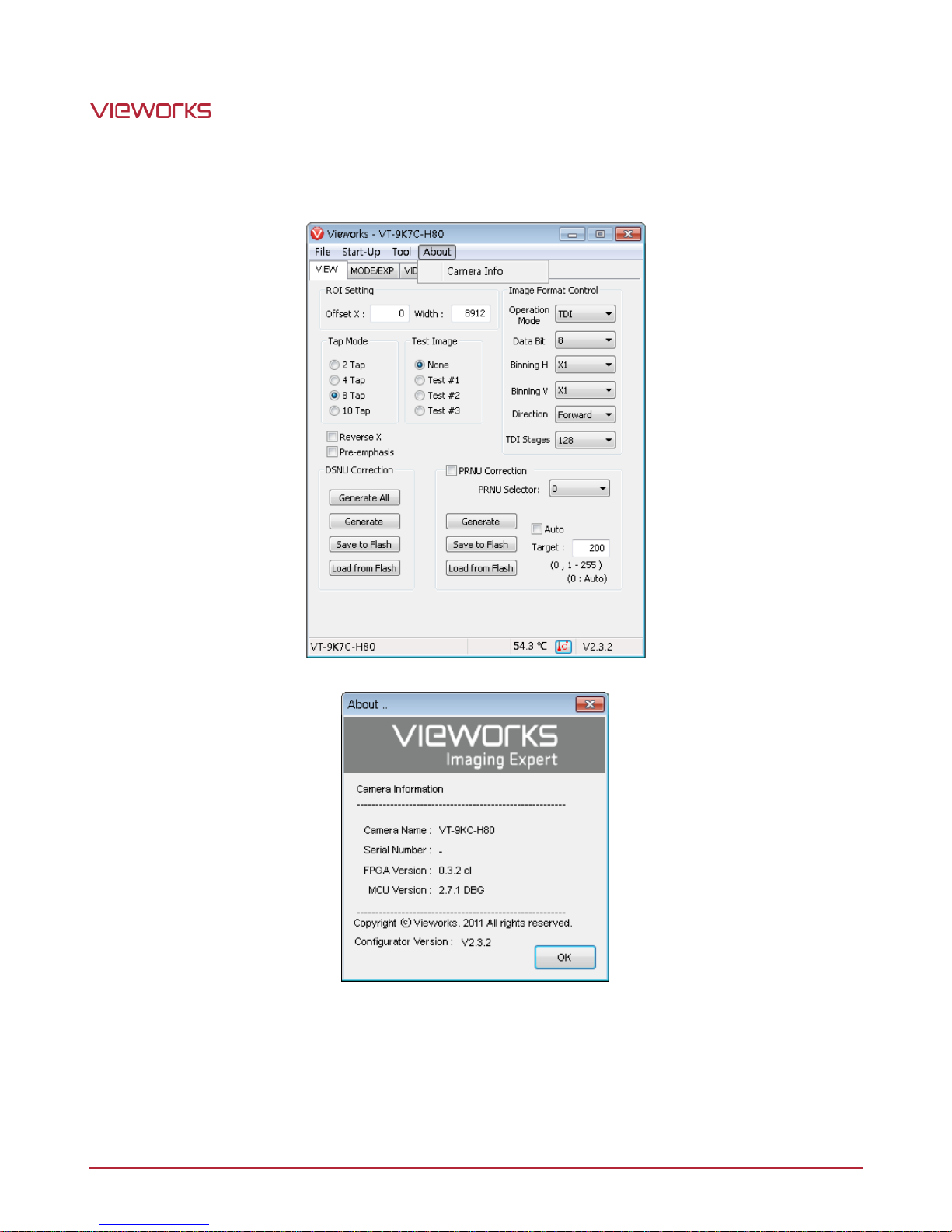
VT Camera Link series
11.2.4 About
Figure 11.5 About Menu
Camera Info: Displays camera information (model name, serial number, version, etc.).
Page 65 of 77 VW40-161-001
Page 66
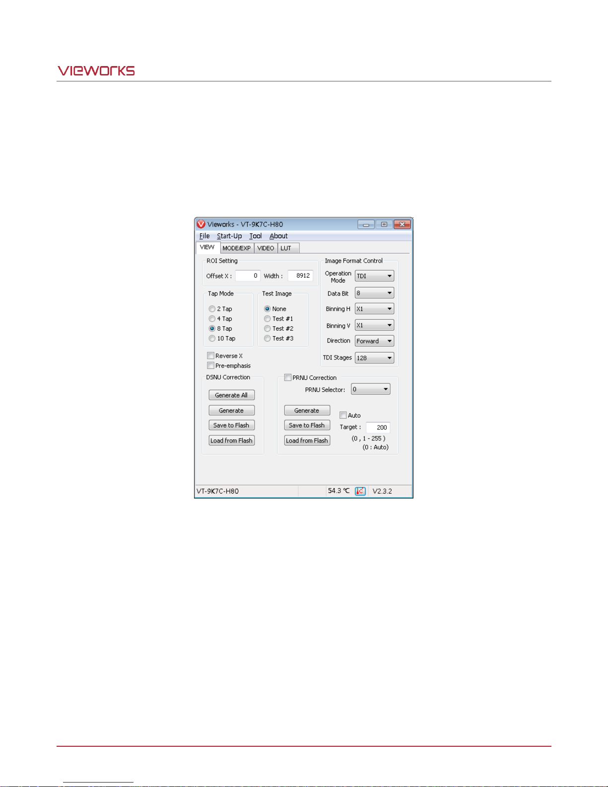
VT Camera Link series
11.3 Tab
11.3.1 VIEW Tab
The VIEW tab allows you to set the camera’s region of interest (ROI), test image mode, operation mode, data
bit, Camera Link output mode, binning, scan direction, TDI stage, DSNU, PNRU features, etc.
ROI Setting: Sets the camera’s ROI by using the Offset X and Width input box.
Tap Mode: Selects a Camera Link output mode.
Test Image: Selects whether to apply test image and a type of test images.
Reverse X: Sets the Reverse X feature On or Off.
Pre-emphasis: Sets the Pre-emphasis On or Off.
Image Format Control: Sets the Operation Mode, bit depth of data output, Binning feature, Scan
Direction and TDI Stages.
DSNU Correction: Sets the DSNU Correction feature.
PRNU Correction: Sets the PRNU Correction feature.
Page 66 of 77 VW40-161-001
Figure 11.6 VIEW Tab
Page 67
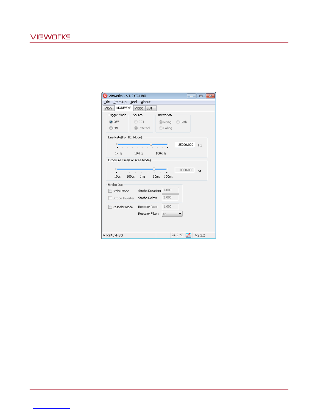
VT Camera Link series
11.3.2 MODE/EXP Tab
The MODE/EXP tab allows you to configure the camera’s trigger mode, line rate, exposure time, strobe and
trigger rescaler.
Figure 11.7 MODE/EXP Tab
Trigger Mode: Sets the trigger mode.
Source: Selects a source signal for exposure triggering.
Activation: Selects a polarity of trigger signals.
Exposure Time: Sets exposure time when the Operation Mode is set to Area and the Trigger
Mode is set to Off.
Line Rate: Sets line rate when the Operation Mode is set to TDI and the Trigger Mode
is set to Off.
Strobe Out: Sets the Strobe Mode.
Rescaler Mode: Sets the trigger Rescaler Mode.
Page 67 of 77 VW40-161-001
Page 68

VT Camera Link series
11.3.3 VIDEO Tab
The VIDEO Tab allows you to adjust the camera’s gain and black level settings.
Figure 11.8 VIDEO Tab
Analog Gain: Sets an analog gain value.
Digital Gain: Sets a digital gain value.
Black level: Sets a black level value.
Page 68 of 77 VW40-161-001
Page 69

VT Camera Link series
12 Troubleshooting
When you have a problem with a Vieworks camera, please check the followings:
If no image is displayed on your computer,
Ensure that all cable connections are secure.
Ensure that the power supply is properly connected.
Ensure that trigger signals are applied correctly when you operate the camera with trigger signals.
If images are not clear,
Ensure the camera lens or glass is clean.
Check the lens aperture is adjusted properly.
If images are dark,
Ensure the camera lens is not blocked.
Check the line rate is set properly.
Check the aperture is opened properly.
Check the digital gain value is not set too small.
If you identify abnormal operation or overheating sign,
Ensure the power supply is properly connected.
Stop using the camera when you notice smoke or abnormal overheating.
If the Trigger Mode is not working correctly,
Ensure that the CC1 settings on the frame grabber are configured correctly when you use CC1
triggering.
Ensure that cable connections are secure when you use external triggering.
If there is a communication failure between the camera and user’s computer,
Ensure that the Camera Link cable connections are secure.
Ensure that you have configured a frame grabber in your computer and the camera is connected to the
frame grabber correctly.
Page 69 of 77 VW40-161-001
Page 70
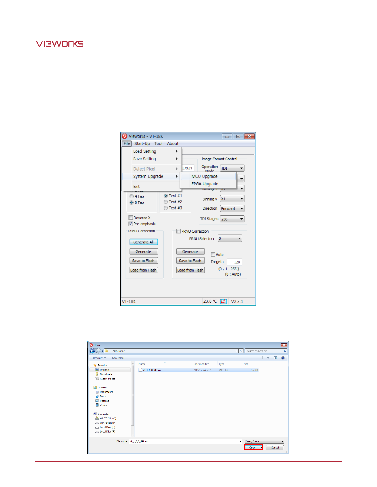
VT Camera Link series
Appendix A Field Upgrade
A.1 MCU
1. Select File > System Upgrade > MCU Upgrade in the Configurator.
2. Search and select the provided MCU file (*.mcu) and click Open.
Page 70 of 77 VW40-161-001
Page 71
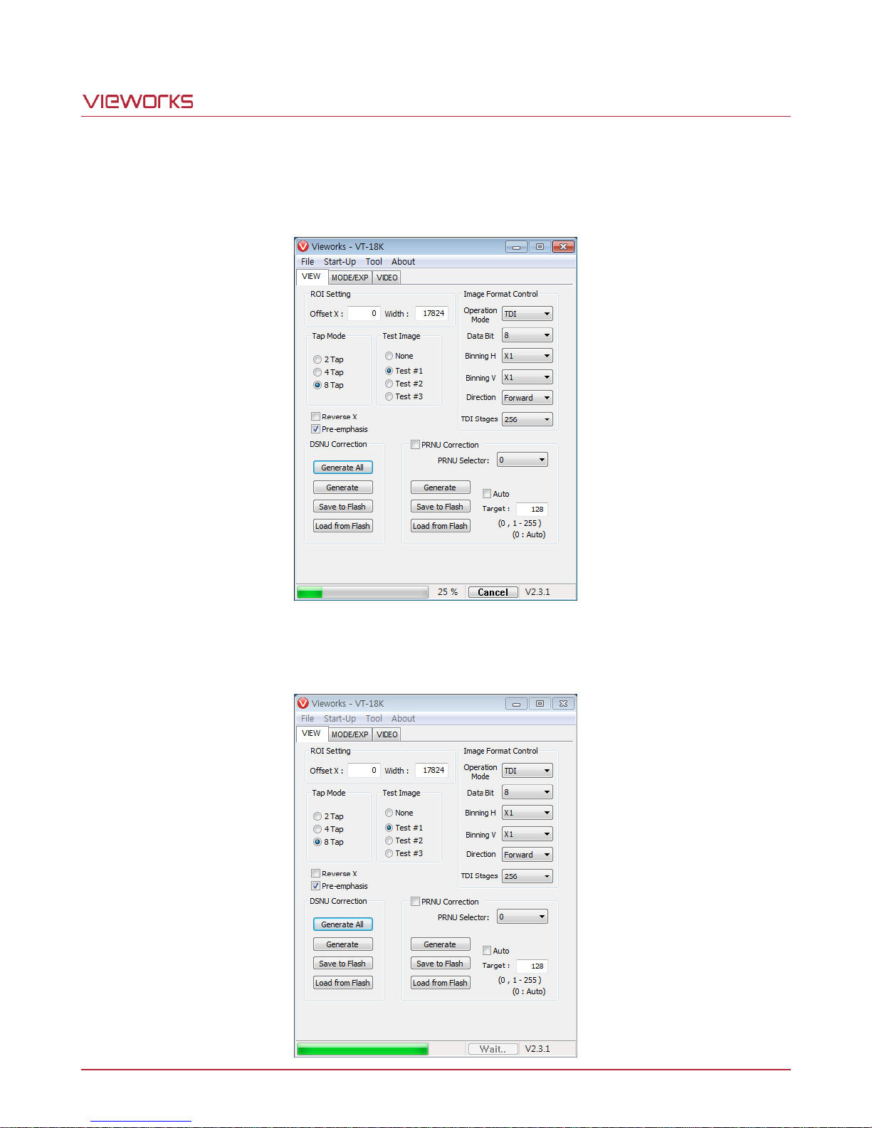
VT Camera Link series
3. The Configurator starts downloading MCU upgrade file to the camera and downloading status is displayed
at the bottom of the window. This process may require several minutes to complete. If you want to cancel
the upgrade process, click Cancel.
4. Once the download is complete, the saving process will begin. If a power failure occurs during the saving
process, the camera cannot be restored. Make sure that the power connection is secure.
Page 71 of 77 VW40-161-001
Page 72
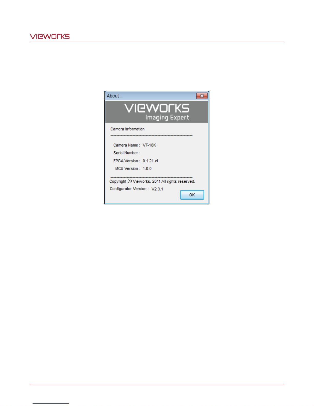
VT Camera Link series
5. Once all the processes are complete, turn the camera power off and turn it back on again. Select Tool >
Terminal and enter the ‘gmv' command to confirm the version. Or, select About > Camera Info to confirm
the MCU version.
Page 72 of 77 VW40-161-001
Page 73
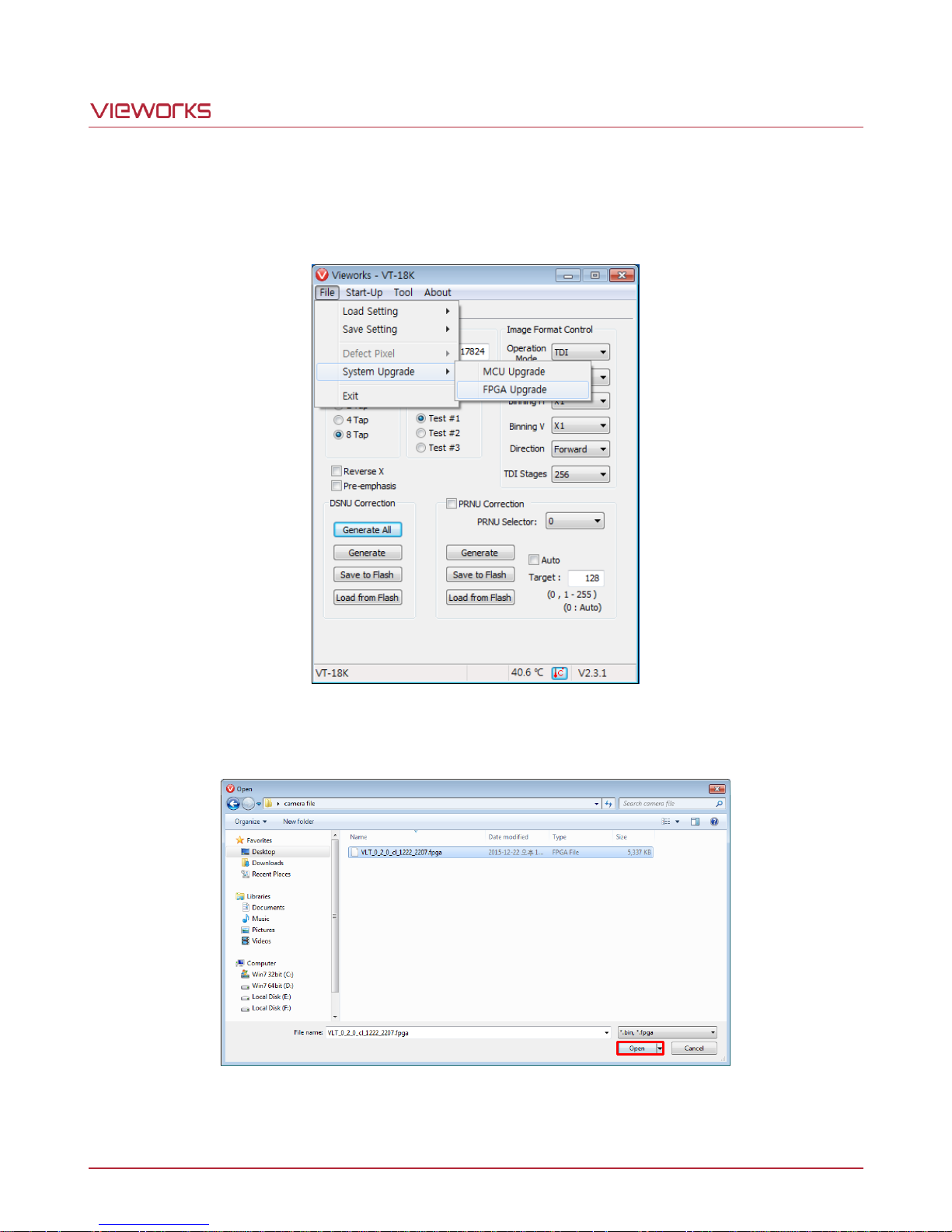
VT Camera Link series
A.2 FPGA
1. Select File > System Upgrade > FPGA Upgrade in the Configurator.
2. Search and select the provided FPGA file (*.fpga) and click Open.
3. The subsequent processes are identical to those of MCU upgrade.
Page 73 of 77 VW40-161-001
Page 74
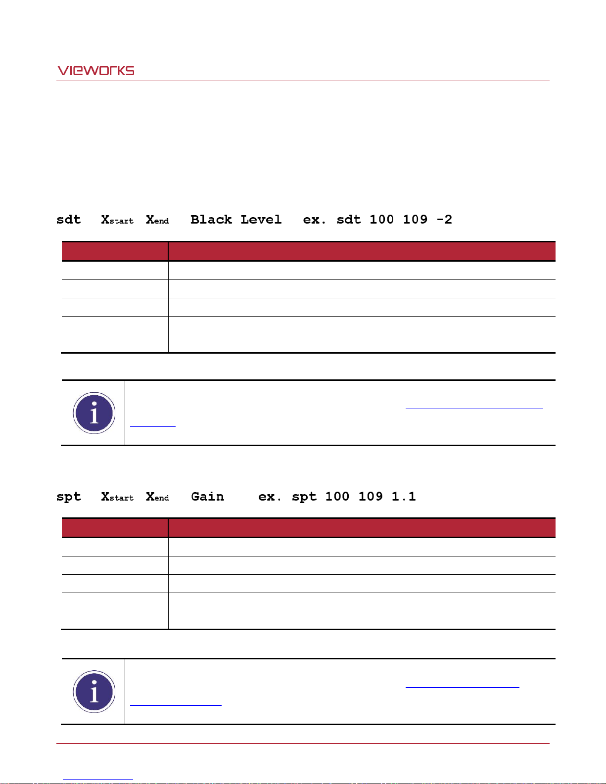
VT Camera Link series
Command Syntax
Description
sdt
Applies the additional DSNU correction value to the specified region of the sensor.
Xstart
X coordinate of a start pixel
Xend
X coordinate of an end pixel (If you specify a pixel, you can leave this value blank.)
Black Level
Sets an additional DSNU correction value [Black Level value to be added to the
specified region (DN, digital number)].
For more details on how to save or load DSNU values, refer to 9.8 Dark Signal Non-uniformity
Correction.
Command Syntax
Description
spt
Applies the additional PRNU correction value to the specified region of the sensor.
Xstart
X coordinate of a start pixel
Xend
X coordinate of an end pixel (If you specify a pixel, you can leave this value blank.)
Gain
Sets an additional PRNU correction value (Gain value to be multiplied to the specified
region)
For more details on how to save or load PRNU values, refer to 9.9 Photo Response Non-
uniformity Correction.
Appendix B Correction Control
The VT Camera Link cameras provide an additional feature to adjust DSNU or PRNU correction values after the
DSNU or PRNU Correction feature is enabled. You can specify a pixel or region of the sensor and the pixel
information from the specified portion will be adjusted according to the user-defined DSNU or PRNU correction
value. The commands related to the additional DSNU Correction are as follows.
Table B.1 Command related to Additional DSNU Correction
The commands related to the additional PRNU Correction are as follows.
Table B.2 Commands related to Additional PRNU Correction
Page 74 of 77 VW40-161-001
Page 75
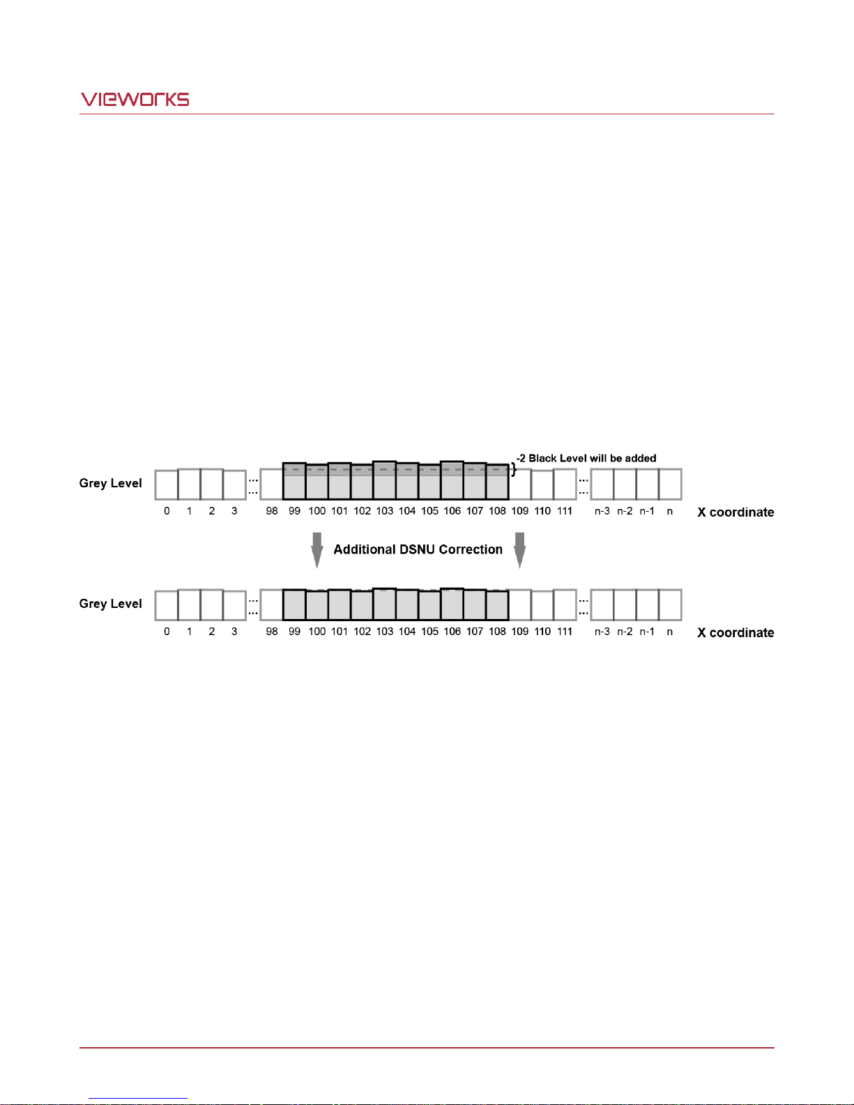
VT Camera Link series
B.1 Adjusting and Saving Additional DSNU Correction Value
For example, if you want to apply -2 black level from the 100th pixel to the 109th pixel, follow the procedures
below.
1. Click Tool > Terminal in the Configurator.
2. Input the sdt 100 109 -2 command into the Terminal input box.
3. Execute the sdd command to save the additional DSNU correction value in the camera’s Flash (nonvolatile) memory. In this case, the previous DSNU values for the current Analog Gain setting value saved in
the memory will be overwritten. To ignore the adjusted DSNU correction values and load the existing values
in the Flash memory, execute the ldd command.
Figure B.1 Additional DSNU Correction
Page 75 of 77 VW40-161-001
Page 76
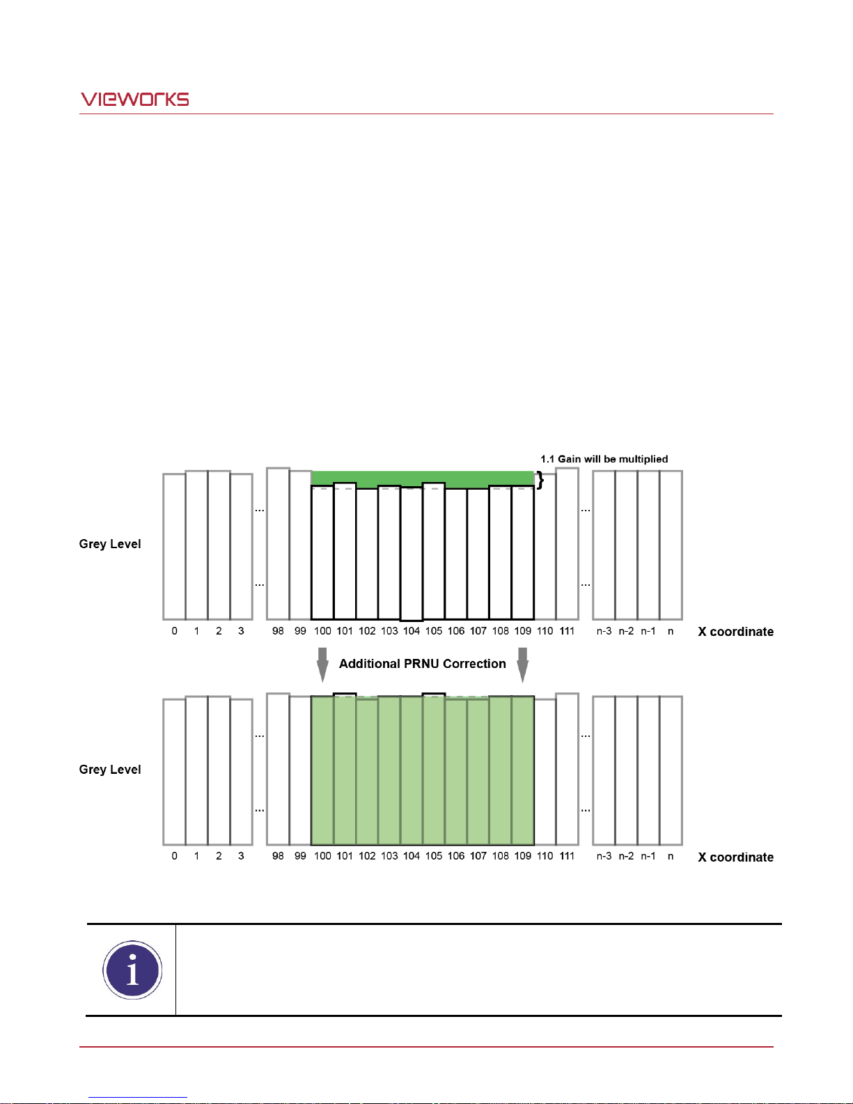
VT Camera Link series
Before executing the spt command, if you set the PRNU Mode to On by using the sprnu
command, you can determine the adjusted PRNU correction values in the acquired line images.
B.2 Adjusting and Saving Additional PRNU Correction Value
For example, if you want to apply 1.1 gain from the 100th pixel to the 109th pixel, follow the procedures below.
1. Click Tool > Terminal in the Configurator.
2. Input the spt 100 109 1.1 command into the Terminal input box.
3. Specify a location to save by using the spi 0/1/2/3/4 command and execute the spd command to save the
additional PRNU correction value in the camera’s Flash (non-volatile) memory. The existing values in the
Flash memory will be overwritten. To ignore the adjusted PRNU correction values and load the existing
values in the Flash memory, specify a location to load from by using the spi 0/1/2/3/4 command and
execute the lpd command.
Figure B.2 Additional PRNU Correction
Page 76 of 77 VW40-161-001
Page 77
 Loading...