


User Manual
English

VQ series
Revision History
Version Date Description
1.0 2013-06-30 Initial Release
1.1 2014-01-02 Added VQ-310G-400
1.2 2014-03-14
Added VQ-2MG-20
Modified descriptions for Status LED on VQ-310G-M400
2 of 109 RA14-133-016

VQ series
Contents
1 Precautions ....................................................................................................................... 6
2 Warranty ............................................................................................................................ 7
3 Compliance & Certifications ............................................................................................ 7
3.1 FCC Compliance ............................................................................................................. 7
3.2 CE : DoC ......................................................................................................................... 7
3.3 KC ................................................................................................................................... 7
4 Package Components ...................................................................................................... 8
5 Product Specifications ..................................................................................................... 9
5.1 Model .............................................................................................................................. 9
5.2 Specifications ................................................................................................................ 10
5.3 Camera Block Diagram (Except VQ-310G-M400).......................................................... 13
5.4 Camera Block Diagram (VQ-310G-M400) ..................................................................... 14
5.5 Sensor Information ........................................................................................................ 15
5.5.1 Mono Camera Spectral Response ................................................................................................. 15
5.5.2 Color Camera Spectral Response .................................................................................................. 18
5.6 Mechanical Specification ............................................................................................... 20
6 Software Licensing Information .................................................................................... 23
7 Installation ....................................................................................................................... 24
7.1 Mount Plate (Except VQ-310G-M400) ........................................................................... 25
7.2 Precaution to Center the Image Sensor ......................................................................... 25
7.3 Precaution about Blurring Compared to Center ............................................................. 25
7.4 Installing Vieworks Imaging Solution .............................................................................. 25
8 Camera Interface ............................................................................................................. 26
8.1 General Description ....................................................................................................... 26
8.2 RJ-45 Jack .................................................................................................................... 27
8.3 Power Input and Control I/O Receptacle (Except VQ-310G-M400) ................................ 28
8.4 Power Input and Control I/O Receptacle (VQ-310G-M400) ........................................... 29
8.5 Trigger Input Circuit ....................................................................................................... 30
8.6 I/O Output Ci rc u it ........................................................................................................... 31
9 Acquisition Control ......................................................................................................... 32
9.1 Overview ....................................................................................................................... 32
9.2 Acquisition Start/Stop Commands and Acquisition Mode ............................................... 35
3 of 109 RA14-133-016

VQ series
9.3 Exposure Start Trigger ................................................................................................... 36
9.3.1 Trigger Mode .................................................................................................................................. 36
9.3.2 Using a Software Trigger Signal ..................................................................................................... 39
9.3.3 Using an External Trigger Signal .................................................................................................... 40
9.3.4 Trigger Delay .................................................................................................................................. 43
9.4 Setting the Exposure Time ............................................................................................. 44
9.4.1 Exposure Auto (Except VQ-5MG-16) ............................................................................................. 45
9.5 Overlapping Exposure with Sensor Readout ................................................................. 46
9.6 CCD Real Exposure (Except VQ-310G-M400) .............................................................. 49
9.6.1 Timed Exposure Mode .................................................................................................................... 49
9.6.2 Trigger Width Exposure Mode ........................................................................................................ 50
9.7 CMOS Real Exposure (VQ-310G-M400) ....................................................................... 52
9.7.1 Timed Exposure Mode .................................................................................................................... 52
9.7.2 Trigger Width Exposure Mode ........................................................................................................ 53
9.8 Electronic Shutter Operation .......................................................................................... 54
9.8.1 Global Shutter ................................................................................................................................. 54
9.9 Acquisition Timing Chart ................................................................................................ 55
9.10 Maximum Allowed Frame Rate ...................................................................................... 57
9.10.1 Increasing the Maximum Allowed Frame Rate ....................................................................... 58
10 Camera Features ............................................................................................................. 59
10.1 Image R egion of Interest ............................................................................................... 59
10.2 Binning (Except VQ-310G-M400) .................................................................................. 64
10.3 Sensor Tap Settings ...................................................................................................... 66
10.4 Pixel Format .................................................................................................................. 69
10.4.1 Mono 8 .................................................................................................................................... 70
10.4.2 Mono 10 .................................................................................................................................. 71
10.4.3 Mono 10 Packed ..................................................................................................................... 71
10.4.4 Mono 12 .................................................................................................................................. 72
10.4.5 Mono 12 Packed ..................................................................................................................... 72
10.4.6 Bayer Formats ........................................................................................................................ 73
10.4.7 YUV Formats .......................................................................................................................... 74
10.5 Stream Hold .................................................................................................................. 77
10.6 Inter-Packet Delay ......................................................................................................... 78
10.7 Data ROI ....................................................................................................................... 79
10.8 Exposure Auto and Gain Auto (Except VQ-5MG-16) ...................................................... 81
4 of 109 RA14-133-016

VQ series
10.9 Balance White Auto (Color Cameras) ............................................................................ 84
10.10 Gain and Black Level ..................................................................................................... 85
10.10.1 Analog Domain ....................................................................................................................... 85
10.10.2 Digital Domain ......................................................................................................................... 86
10.11 LUT (Except VQ-5MG-16) ............................................................................................. 87
10.12 Defective Pixel Correct io n ............................................................................................. 89
10.12.1 Correction Method .................................................................................................................. 89
10.12.2 Correction Method in Binning Mode (Except VQ-310G-M400) .............................................. 90
10.13 Temperature Monitor ..................................................................................................... 91
10.14 Status LED .................................................................................................................... 91
10.15 Test Image ..................................................................................................................... 92
10.16 Digital IO Control ........................................................................................................... 94
10.17 Event Control ................................................................................................................. 96
10.18 Device User ID .............................................................................................................. 97
10.19 Device Reset ................................................................................................................. 97
10.20 User Set Control ............................................................................................................ 98
10.21 Field Upgrade ................................................................................................................ 98
Appendix A Defective Pixel Map Download ................................................................... 99
Appendix B LUT Download (Except VQ-5MG-16) ........................................................ 101
B.1 Luminance LUT ........................................................................................................... 101
B.1.1 Gamma Graph Download ............................................................................................................. 101
B.1.2 CSV File Download ...................................................................................................................... 103
Appendix C Fie ld Upgrade ............................................................................................. 105
C.1 MCU ............................................................................................................................ 105
C.2 FPGA .......................................................................................................................... 107
C.3 XML ............................................................................................................................. 108
5 of 109 RA14-133-016

VQ series
1 Precautions
General
Do not drop, disassemble, repair or alter the device. Doing so may damage the camera
electronics and cause an electric shock.
Do not let children touch the device without supervision.
Stop using the device and contact the nearest dealer or manufacturer for technical
assistance if liquid such as water, drinks or chemicals gets into the device.
Do not touch the device with wet hands. Doing so may cause an electric shock.
Do not store the device at a higher temperature. In addition, maintain the ambient
temperature in a range of 0℃ to 40℃ during operation. Otherwise the device may be
damaged by excessively high temperatures.
Installation and Maintenance
Do not install in dusty or dirty areas - or near an air conditioner or heater to reduce the
Avoid installing and operating in an extreme environment where vibration, heat, humidity,
Do not apply excessive vibration and shock to the device. This may damage the device.
Avoid direct exposure to a high intensity light source. This may damage the image
Do not install the device under unstable lighting conditions. Severe lighting change will
Do not use solvents or thinners to clean the surface of the device. This can damage the
Power Supply
Applying incorrect power can damage the camera. If the voltage applied to the camera is
risk of damage to the device.
dust, strong magnetic fields, explosive/corrosive mists or gases are present.
sensor.
affect the quality of the image produced by the device.
surface finish.
greater or less than the camera’s nominal voltage, the camera may be damaged or
operate erratically. Please refer to
5.2 Specifications for the camera’s nominal voltage.
6 of 109 RA14-133-016
※ Vieworks Co., Ltd. does NOT provide power supplies with the devices.
Make sure the power is turned off before connecting the power cord to the camera.
Otherwise, damage to the camera may result.

VQ series
2 Warranty
Do not open the housing of the camera. The warranty becomes void if the housing is opened.
For information about the warranty, please contact your local dealer or factory representative.
3 Co m pliance & Certifications
3.1 FCC Compliance
This equipment has been tested and found to comply with the limits for a Class A digital device, pursuant to part
15 of the FCC Rules. These limits are designed to provide reasonable protection against harmful interference
when the equipment is operated in a commercial environment. This equipment generates, uses, and can radiate
radio frequency energy and, if not installed and used in accordance with the instruction manual, may cause
harmful interference to radio communications. Operation of this equipment in a residential area is likely to cause
harmful interference in which case the user will be required to correct the interference at his own expenses.
3.2 CE : DoC
EMC Directive 2004/108/EC.
Testing Standard EN 55022:2006+A1:2007, EN 55024:1998+A1:2001+A2:2003
Class A
3.3 KC
KCC Statement
Type Description
Class A
(Broadcasting Comm unic ation
Device for Office Use)
This device obtained EMC registration for office use (Class A), and may
be used in places other than home. Sellers and/or users need to take
note of this.
7 of 109 RA14-133-016

VQ series
4 Package Components
Package Components
VQ Camera
Mount Plate (Optional, Except VQ-310G-M400)
8 of 109 RA14-133-016

VQ series
5 Product Specifications
5.1 Model
VQ series is a progressive scan, high performance industrial area scan camera. All features of VQ series can be
programmed and easily updated in the field through Gigabit Ethernet interface. The camera is developed based
on GenICam standard. The image processing and controls of VQ series are based on embedded FPGA with
32 bit RISC microprocessor.
Main Features
×1, ×2, ×3, ×4 Horizontal and Vertical Binning (Except VQ-310G-M400)
Stream Hold
Inter-Packet Delay
Camera Image Memory: 64MB
Field Upgradable Firmware
Pixel Defect Correction (Binning Mode: 2×2, 4×4)
Electronic Shutter – Global Shutter
Output Pixel Format – 8/10/12 bit
Gigabit Ethernet Interface
Temperature Monitor
9 of 109 RA14-133-016

VQ series
ICX424 AL/AQ
ICX445 AL/AQ
ICX274 AL/AQ
YUV422 Packed, YUV422 (YUYV) Packed
5.2 Specifications
VQ series technical specifications are as follows.
VQ Series VQ-310G-120 VQ-1300G-30 VQ-2MG-20
Active Image (H × V)
Sensor Type
Pixel Size
Optical Size 1/3” 1/3” 1/1.8”
Output
Format
Camera Interface Gigabit Ethernet
Electronic Shutter Global Shutter
Max. Frame Rate at Full Resolution 120 fps 30 fps 20 fps
Dynamic Range
Shutter Speed (10 ㎲ step) 22 ㎲~ 7 s 9 ㎲~ 7 s 30 ㎲~ 7 s
Partial Scan (Max. Speed) 451 fps at 60 Lines 118 fps at 120 Lines 90 fps at 154 Lines
Binning
Lookup Table G=1.0, User Defined Lookup Table (LUT)
Black Level Adjustable (0 ~ 128 LSB at 12 bit, 256 steps)
Mono Mono 8, Mono 10, Mono 12, Mono 10 Packed, Mono 12 Packed
Color
656 × 488
SONY
7.4 ㎛ × 7.4 ㎛ 3.75 ㎛ × 3.75 ㎛ 4.4 ㎛ × 4.4 ㎛
Bayer BG 8, Bayer BG 12, Bayer BG 12Packed
> 52 ㏈ > 48 ㏈
×1, ×2, ×3, ×4 (Horizontal and Vertical Independent)
1296 × 960 1624 × 1232
SONY
SONY
Analog Gain
Exposure Mode
External Trigger
Software Trigger Asynchronous, Program mable via Camera API
Camera Image Memory 64 MB
Auto Control Auto Gain, Auto Exposure, Auto White Balance
API SDK Vieworks Imaging Solution 6.X
Lens Mount C-mount or CS-mount
Power Power over Ethernet(802.3af) or 8 ~ 38 V DC
Environmental
Mechanical
Table 5.1 Specifications of VQ series (VQ-310G-120/1300G-30/2MG-20)
10 of 109 RA14-133-016
×1 ~ ×40 (0 ~ 32 ㏈)
Timed Exposure, Trigger Width Exposure, Double Exposure
3.3 V ~ 24.0 V, 10 ㎃, Asynchronous, optically isolated
Operating: 0℃ ~ 40℃, Storage : -40℃ ~ 70℃
29 ㎜ × 29 ㎜ × 56.4 ㎜ 91g (with C-mount)
29 ㎜ × 29 ㎜ × 51.4 ㎜ 86g (with CS-mount)

VQ series
ICX625 AL/AQ
VQ Series VQ-5MG-16
Active Image (H × V) 2448 × 2056
Sensor Type
Pixel Size
3.45 ㎛ × 3.45 ㎛
SONY
Optical Size 2/3”
Mono Mono 8, Mono 10, Mono 10 packed, Mono 12, Mono 12 packed
Output Format
Color Bayer RG8, Bayer RG12, Bayer RG12 packed
Camera Interface Gigabit Ethernet
Electronic Shutter Global Shutter
Max. Frame Rate at Full Resolution
Dynamic Range
16 fps
> 52 ㏈
Shutter Speed (10 ㎲ step) 39 ㎲~ 7 s
Partial Scan (Max. Speed) 41 fps at 256 Lines
Binning
×1, ×2, ×3, ×4
(Horizontal and Vertical Independent)
Lookup T able N/A
Black Level
Analog Gain
Adjustable (0 ~ 128 LSB at 12 bit, 256 steps)
×1 ~ ×40 (0 ~ 32 ㏈)
Exposure Mode Timed Exposure, Trigger Width Exposure, Double Exposure
External Trigger
3.3 V ~ 24.0 V, 10 ㎃, Asynchronous, optically isolated
Software Trigger Asynchronous, Programmable via Camer a API
Camera Image Memory 64 MB
Auto Control Auto White Balance
API SDK Vieworks Imaging Solution 6.X
Lens Mount C-mount or CS-mount
Power Power over Ethernet (802.3af) or 8 ~ 38 V DC
Environmental
Operating: 0℃ ~ 40℃, Storage : -40℃ ~ 70℃
35×35×59.7 ㎜ 83g (with C -mount)
Mechanical
35×35×54.7 ㎜ 83g (With CS-mount)
Table 5.2 Specifications of VQ series (VQ-5MG-16)
11 of 109 RA14-133-016

VQ series
CMV 300
VQ Series VQ-310G-M400
Active Image (H × V) 640 × 480
Sensor Type
Pixel Size
CMOSIS
7.4 ㎛ × 7.4 ㎛
Optical Size 1/3”
Output Format Mono 8, Mono 10, Mono 10 packed, Mono 12, Mono 12 packed
Camera Interface Gigabit Ethernet
Electronic Shutter Global Shutter
Max. Frame Rate at Full Resolution
Dynamic Range
400 fps
> 56 ㏈
Shutter Speed (10 ㎲ step) 65 ㎲~ 7 s
Partial Scan (Max. Speed) 7900 fps at 2 Lines
Binning N/A
Lookup T able G=1.0, User Defined Lookup Table (LUT)
Black Level
Analog Gain
Adjustable (0 ~ 256 LSB at 12 bit, 256 steps)
×1, ×1.25, ×1.5, ×1.75, ×2, ×2.5, ×3, ×3.5
Exposure Mode Timed Exposure, Trigger Width Exposure
External Trigger
3.3 V ~ 24.0 V, 10 ㎃, Asynchronous, optically isolated
Software Trigger Asynchronous, Programmable via Camer a API
Camera Image Memory 64 MB
Auto Control Auto Gain, Auto Exposure
API SDK Vieworks Imaging Solutio n 6.X
Lens Mount CS-mount
Power 10 ~ 14 V DC (Max. 3W)
Environmental
Mechanical
Operating: -10℃ ~ 55℃, Storage : -40℃ ~ 70℃
44×29×60 ㎜ 100g (With CS-mount)
Table 5.3 Specifications of VQ series (VQ-310G-M400)
12 of 109 RA14-133-016

VQ series
5.3 Camera Block Diagram (E xce pt V Q-310G-M400)
Figure 5.1 Camera Block Diagram (Except VQ-310G-M400)
All controls and data processing of the camera are carried out in one FPGA chip. The FPGA generally consists
of a 32 bit RICS Micro-Controller and Process i ng & Control Log ic .
The Micro-Controller receives commands from the user through the Gigabit Ethernet interface and then
processes them. The FPGA controls the Timing Generators (TGs) and the Analog Front End (AFE) chips where
the TGs generate CCD control signals and AFE chips convert analog CCD output to digital values to be
accepted by the Processing & Control Logic. The Processing & Control Logic processes the image data received
from AFE and then transmits data through the Gigabit Ethernet interface. And also, the Processing & Control
Logic controls the trigger input and output signal which are sensitive to time. Furthermore, DDR2 for operating
Micro-Controller, for used as Gigabit Ethernet frame buffer and for used as a frame buffer to process images,
Gigabit Ethernet Controller and Flash memory for saving system codes and defect coordinates are installed
outside FPGA.
13 of 109 RA14-133-016

VQ series
5.4 Camera Block Diagram (VQ-310G-M400)
Figure 5.2 Camera Block Diagram (VQ-310G-M400)
All controls and data processing of the camera are carried out in one FPGA chip. The FPGA generally consists
of a 32 bit RICS Micro-Controller and Processing & Co ntrol Log ic.
The Micro-Controller receives commands from the user through the Gigabit Ethernet interface and then
processes them.
The Processing & Control Logic processes the image data received from the CMOS sensor and then transmits
data through the Gigabit Ethernet interface. And also, the Processing & Control Logic controls the trigger inputs
and strobe outputs which are sensitive to time. Furthermore, Flash and DDR2 SDRAM are installed outside
FPGA. The Flash contains the firmware that operates the Micro-Controller and DDR2 SDRAM is used for frame
buffer to process images.
14 of 109 RA14-133-016

VQ series
5.5 Sensor Information
5.5.1 Mono Camera Spectral Re spons e
The following graphs show the spectral response for VQ series monochrome cameras.
Figure 5.3 VQ-310G-M120 Spectral Response
15 of 109 RA14-133-016

VQ series
Figure 5.4 VQ-1300G-M30 Spectral Response
Figure 5.5 VQ-2MG-M20 Spectral Response
16 of 109 RA14-133-016

VQ series
Figure 5.6 VQ-5MG-M16 Spectral Response
Figure 5.7 VQ-310G-M400 Spectral Response
17 of 109 RA14-133-016

VQ series
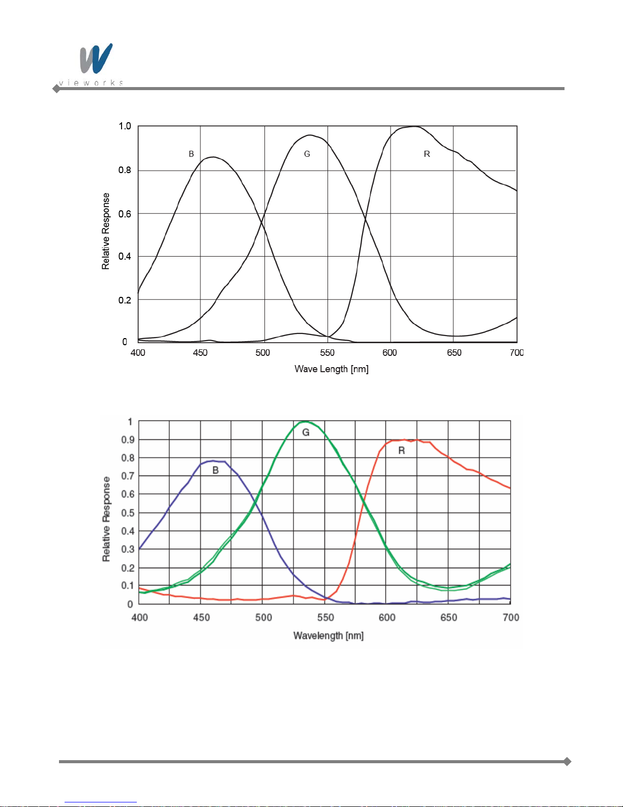
5.5.2 Color Camera Spectral Res pons e
The following graphs show the spectral response for VQ series color cameras.
Figure 5.8 VQ-310G-C120 Spectral Response
Figure 5.9 VQ-1300G-C30 Spectral Response
18 of 109 RA14-133-016
VQ series
Figure 5.10 VQ-2MG-C20 Spectral Response
Figure 5.11 VQ-5MG-C16 Spectral Response
19 of 109 RA14-133-016

VQ series
5.6 Mechanical Specification
The camera dimensions in millimeters are as shown in the following figure.
Figure 5.12 VQ-310G-120, 1300G-30 and 2MG-20 C-mount Mechanical Dimension
Figure 5.13 VQ-310G-120, 1300G-30 and 2MG-20 CS-mount Mechanical Dimension
20 of 109 RA14-133-016

VQ series
Figure 5.14 VQ-5MG-16 C-mount Mechanical Dimension
Figure 5.15 VQ-5MG-16 CS-mount Mechanical Dimension
21 of 109 RA14-133-016

VQ series
Figure 5.16 VQ-310G-M400 CS-mount Mechanical Dimension
22 of 109 RA14-133-016

VQ series
6 Software Licensing Informat ion
The software in VQ series includes the lightweight IP (lwIP) TCP/IP implementation. The software licensing
information for this implementation is as follows.
Copyright (c) 2001-2004 Swedish Institute of Computer Science.
All rights reserved.
Redistribution and use in source and binary form s, with or without m odification, are permitted provide d
that the following conditions are met:
1. Redistributions of source c ode must retain the abo ve copyright notice, this list of conditions and
the following disclaimer.
2. Redistributions in binary form must reproduce the ab ove copyright notice, t his list of conditions
and the following disclaimer in the documentation and/or other materials provided with the
distribution.
3. The name of the author may not be used to endorse or promote products derived from this
software without specific prior written permission.
THIS SOFTWARE IS PROVIDED BY THE AUTHOR “AS IS” AND ANY EXPRESS OR IMPLIED
WARRANTIES, INCLUDING, BUT NOT LIMITED TO, THE IMPLIED WARRANTIES OF
MERCHANTABILITY AND FITNESS FOR A PARTICULAR PURPOSE ARE DISCLAIMED.
IN NO EVENT SHALL THE AUTHOR BE LIABLE FOR ANY DIRECT, INDIRECT, INCIDENTAL, SPECIAL,
EXEMPLARY, OR CONSEQUENTIAL DAMAGES (INCLUDING, BUT NOT LIMITED TO,
PROCUREMENT OF SUBSTITUTE GOODS OR SERVICES; LOSS OF USE, DATA, OR PROFITS; OR
BUSINESS INTERRUPTION) HOWEVER CAUSED AND ON ANY THEORY OF LIABILITY, WHETHER
IN CONTRACT, STRICT LIABILITY, OR TORT (INCLUDING NEGLIGENCE OR OTHERWISE) ARISING
IN ANY WAY OUT OF THE USE OF THIS SOFTWARE, EVEN IF ADVISED OF THE POSSIBILITY OF
SUCH DAMAGE.
23 of 109 RA14-133-016

VQ series
7 Installation
The following instructions assume that you have installed an Ethernet card including related software and
Vieworks Imaging Solution. For more information, refer to Vieworks Imaging Solution Installation Manual.
To connect the camera to your PC, follow the steps below.
1. Make sure that the power supply is not connected to the camera and your PC is turned off.
Go on to step 2 if you are using a power supply.
Go on to step 3 if you are using a Power over Ethernet (PoE) injector.
2. If you are using a power supply:
a. Plug one end of an Ethernet cable into the RJ45 jack on the camera and the other end of the Ethernet
cable into the Ethernet card in your PC.
b. Connect the plug of the power adapter to the 6-pin Power Input and Control I/O receptacle on the
camera.
c. Plug the power adapter into a working electrical outlet.
3. If you are using a PoE injector:
a. Plug one end of an Ethernet cable into the network connector on the PoE injector and the other end of
the Ethernet cable into the Ethernet card in your PC.
b. Plug the PoE injector into a working electrical outlet.
c. Connect one end of an Ethernet cable to the network connector on the PoE injector labeled “PoE” and
plug the other end of the cable into the RJ45 jack on the camera.
4. Verify all the cable connections are secure.
Precaution for using Power over Ethernet
Make sure that your Ethernet card or Power over Ethernet injector is compliant with
IEEE 802.af standard if you want to supply power to the camera using PoE.
Yon do not need to connect a power adapter to the camera if you supply power to the
camera using PoE.
The PoE feature is not supported on VQ-310G-M400.
24 of 109 RA14-133-016

VQ series
7.1 Mount Plate (Except VQ-310G-M400)
The mount plate is provided as an optional item.
The camera can be fixed without using this mount plate.
7.2 Precauti on to C enter the Imag e S ensor
Users do not need to center the image sensor as it is adjusted as factory default settings.
When you need to adjust the center of the image sensor, please contact your local dealer or the
manufacturer for technical assistance.
7.3 Precaution about Blurring Compared to Center
Users do not need to adjust the tilt as it is adjusted as factory default settings.
If the tilt settings need to be adjusted inevitably, please contact your local dealer or factory representative for
technical support.
7.4 Installing Vieworks Imaging Solution
You can download the Vieworks Imaging Solution at machinevision.vieworks.com. You should perform the
software installation first and then the hardware installation.
25 of 109 RA14-133-016

VQ series
8 Camera Interface
8.1 General Description
As shown in the figure below, 2 types of connectors and a status indicator LED are located on the back of the
camera and have the functions as follows
① RJ-45 Jack: controls video data and the camera. Since the camera is Power
over Ethernet capable, the jack can also be used to provide power
to the camera.
② 6 pin Circular Receptacle (male): provides access to the camera’s I/O lines and power to the camera
(if PoE is not used).
③ Status LED (Green): displays power status and operation mode.
④ 12 pin Circular Receptacle (male): provides access to the camera’s I/O lines and power to the camera.
①
②
③
Figure 8.1 VQ Series Back Panel
①
④
26 of 109 RA14-133-016
③
Figure 8.2 VQ-310G-M400 Back Panel

VQ series
8.2 RJ-45 Jack
The 8-pin RJ-45 jack provides Ethernet access to the camera. The jack can also be used to provide Power over
Ethernet (IEEE 802.af compliant) to the camera. Pin assignments for the RJ-45 jack adhere to the Ethernet
standard.
① ②
Figure 8.3 RJ-45 Jack
① Ethernet Link LED (Green): LED is lit when Ethernet link is active.
② Ethernet Active LED (Orange): LED blinks when Rx/Tx is active.
PAIR List Pin Signal Name Type Description
PA IR 0
PA IR 1
PA IR 2
PA IR 3
1 +TXA Differential Gigabit Ethernet Transceiver
2 -TXA Differential Gigabit Ethernet Transceiver
3 +TXB Differential Gigabit Ethernet Transceiver
6 -TXB Differential Gigabit Ethernet Transceiver
4 +TXC Differential Gigabit Ethernet Transceiver
5 -TXC Differential Gigabit Ethernet Transceiver
7 +TXD Differential Gigabit Ethernet Transceiver
8 -TXD Differential Gigabit Ethernet Transceiver
Table 8.1 Pin Assignments for the RJ-45 Jack
27 of 109 RA14-133-016

VQ series
1
2
3 4
5
6
8.3 Power Input an d Control I/ O Receptacle (Except VQ -310G-
M400)
The Power Input and Control I/O receptacle is a Hirose 6-pin connector (part # HR10A-7R-6PB) and consists of
a power input, an external trigger signal input and I/O (default: Strobe) output port.
The pin assignments and configurations are as follows:
Figure 8.4 Pin A ssignments for 6-pin Power Input and Control I/O Receptacle
Pin Number Signal Type Description
1 +12V DC Input Camera Power +12V DC
2 Trigger Input + Input 3 Trigger Input - Input -
4
5 I/O Output - - 6 DC Ground Input Camera Power GND
Table 8.2 Pi n Arrangement of Power Input and Control I/O Receptacle
The mating connector is a Hirose 6-pin plug (part # HR10A-7P-6S) or the equivalent connectors. The power
adapter is recommended to have at least 1 A current output at 12 V DC ±10% voltage output (Users need to
purchase the power adapter separately).
I/O Output +
Output -
(Default: Strobe Out)
Precaution for Power Input
Make sure the power is turned off before connecting the power cord to the camera.
Otherwise, damage to the camera may result.
28 of 109 RA14-133-016
If the camera input voltage is greater than 38 V, damage to the camera may result.

VQ series
8.4 Power Input and Control I/O Receptacle (VQ-310G-M400)
VQ-310G-M400’s Power Input and Control I/O receptacle is a Hirose 12-pin connector (part # HR10A-10R12PB). The pin assignments and configurations are as follows:
Figure 8.5 Pin A ssignments for 12-pin Power Input and Control I/O Receptacle (VQ-310G-M400)
Pin Number Signal Type Description
1 DC Ground Input Camera Power GND
2 +12 V DC Input Camera Power +12V DC
3 I/O Output - Output -
4
5 Trigger Input - Input 6 Trigger Input + Input -
7-12 N/C - -
Table 8.3 Pi n Arrangement of Power Input and Control I/O Receptacle (VQ-310G-M400)
The mating connector is a Hirose 12-pin plug (part # HR10A-10P-12S) or the equivalent connectors. The power
adapter is recommended to have at least 1 A current output at 12 V DC ±10% voltage output (Users need to
purchase the power adapter separately).
I/O Output +
Output -
(Default: Strobe Out)
Precaution for Power Input
Make sure the power is turned off before connecting the power cord to the camera.
Otherwise, damage to the camera may result.
If the camera input voltage is greater than 14 V, damage to the camera may result.
29 of 109 RA14-133-016

VQ series
PS2801C-1
2.2K 10K
+3.3V
1K
120
2SC2413K
2
1 3
1
3
2
4
5
6
HR10-7R-6PB
Your GND
+3.3V ~ +24V
TRIGGER_INPUT
Camera SideUser Side
8.5 Trigger Input Circuit
The following figure shows trigger signal input circuit of the 6-pin and 12-pin connectors. Transmitted trigger
signal is applied to the internal circuit through a photo coupler. Minimum trigger width that can be recognized by
the camera is 1 ㎲. If transmitted trigger signal is less than 1 ㎲, the camera will ignore the trigger signal.
External trigger circuit example is shown below.
30 of 109 RA14-133-016
Figure 8.6 Trigger Input Schematic
Figure 8.7 Trigger Input Schematic (VQ-310G-M400)

VQ series
1
3
2
4
5
6
HR10-7R-6PB
PS2801C-1
Your GND
270
+3.3V ~ +24V
OUT
Camera SideUser Side
IO_OUT
47
4.7K
2SC2413K
2
1 3
120
120
8.6 I/O Output Circuit
The following figure shows I/O output circuit of the 6-pin and 12-pin connectors. You can change the I/O output
by setting the Digital IO control (refer to chapter
Figure 8.8 I/O Output Schematic
10.16 Digital IO Control).
Figure 8.9 I/O Output Schematic (VQ-310G-M400)
31 of 109 RA14-133-016

VQ series
9 Acquisition Control
This chapter provides detailed information about controlling image acquisition.
Triggering image acquisition
Setting the exposure time
Controlling the camera’s image acquisition rate
Variation of the camera’s maximum allowed image acquisition rate according to the camera settings
9.1 Overview
This section presents an overview of the elements involved with controlling the acquisition of images.
Three major elements are involved in controlling the acquisition of images:
Acquisition Start and Acquisition Stop commands and the Acquisition Mode parameter
The exposure start trigger
Exposure time control
When reading the explanations in the overview and in this entire chapter, keep in mind that
the term frame is typically used to mean a single acquired image.
Acquisition Start and Stop Commands and the Acquisition Mode
The Acquisition Start command prepares the camera to acquire frames. The camera cannot acquire frames
unless an Acquisition Start command has first been executed.
A parameter called the Acquisition Mode has a direct bearing on how the Acquisition Start command
operates.
If the Acquisition Mode parameter is set to Single Frame, you can only acquire one frame after exec uting an
Acquisition Start command. When one frame has been acquired, the Acquisition Start command will expire.
Before attempting to acquire another frame, you must execute a new Acquisition Start command.
If the Acquisition Mode parameter is set to Continuous, an Acquisition Start command does not expire after
a single frame is captured. Once an Acquisition Start command has been executed, you can acquire as many
frames as you like. The Acquisition Start command will remain in effect until you execute an Acquisition Stop
command. Once an Acquisition Stop command has been executed, the camera will not be able to acquire
frames until a new Acquisition Start command is executed.
32 of 109 RA14-133-016

VQ series
Exposure Start Trigger
Applying an exposure start trigger signal to the camera will exit the camera from the waiting for exposure start
trigger acquisition status an d will beg in the process of exposing and reading out a frame (see Figure 9.1).
As soon as the camera is ready to accept another exposure start trigger signal, it will retur n to the waiting for
exposure start trigger acquisition status. A new exposure start trigger signal can then be applied to the camera to
begin another frame exposure.
The exposure start trigger has two modes: off and on.
If the Trigger Mode parameter is set to Off, the camera will generate all required exposure start trigger signals
internally, and you do not need to apply exposure start trigger signals to the camera. The rate at which the
camera will generate the signals and acquire frames will be determined by the way that you set several frame
rate related parameters.
If the Trigger Mode parameter is set to On, you must trigger exposure start by applying exposure start trigger
signals to the camera. Each time a trigger signal is applied, the camera will begin a frame exposure. When
exposure start is being triggered in this manner, it is important that you do not attempt to trigger frames at a rate
that is greater than the maximum allowed (There is a detailed explanation about the maximum allowed frame
rate at the end of this chapter.). Exposure start trigger signals applied to the camera when it is not in a waiting for
exposure start trigger acquisition status will be ignored.
33 of 109 RA14-133-016
Figure 9.1 Exposure Start Triggering

VQ series
Applying Trigger Signals
The paragraphs above mention "applying a trigger signal". There are two ways to apply an exposure start trigger
signal to the camera: via software or via external (commonly referred to as hardware).
To apply trigger signals via Software, you must set the Trigger Source parameter to Software. At that point,
each time a Trigger Software command is executed, the exposure start trigger signal will be applied to the
camera.
To apply trigger signals via External, you must set the Trigger Source parameter to External. At that point,
each time a proper electrical signal is applied to the camera, an occurrence of the exposure start trigger signal
will be recognized by the camera.
Exposure Time Control
When an exposure start trigger signal is applied to the camera, the camera will begin to acquire a frame.
A critical aspect of frame acquisition is how long the pixels in the camera’s sensor will be exposed to light during
the frame acquisition.
If the Trigger Source parameter is set to Software, a parameter called the Exposure Time will determine the
exposure time for each frame. At this point, you must set the Exposure Mode parameter to Timed.
If the Trigger Source parameter is s et to External, there are two m odes of oper a tion : Timed and Trigger Width.
With the Timed mode, the Exposure Time parameter will determine the exposure time for each frame.
With the Trigger Width mode, the way that you manipulate the rise and fall of the external signal will determine
the exposure time. The Trigger Width mode is especially useful if you want to change the exposure time from
frame to frame.
34 of 109 RA14-133-016

VQ series
9.2 Acquisition Start/Stop Commands and Acquisition Mode
Executing an Acquisition Start command prepares the camera to acquire frames. You must execute an
Acquisition Start command before you can begin acquiring frames. Executing an Acquisition Stop command
terminates the camera’s ability to acquire frames. When the camera receives an Acquisition Stop command:
If the camera is not in the process of acquiring a frame, its ability to acquire frames will be terminated
immediately.
If the camera is in the process of acquiring a frame, the frame acquisition process will be allowed to finish
and the camera’s ability to acquire new frames will be terminated.
The camera’s Acquisition Mode parameter has three settings: Single Frame, Multi-Frame and Continuous.
The use of Acquisition Start and Acquisition Stop commands and the camera’s Acquisition Mode parameter
setting are related.
If the camera’s Acquisition Mode parameter is set to Single Frame, after an Acquisition Start command has
been executed, a single frame can be acquired. When acquisition of one frame is complete, the camera will
execute an Acquisition Stop command internally and will no longer be able to acquire frames. To acquire
another frame, you must execute a new Acquisition Start command.
If the camera’s Acquisition Mode parameter is set to Multi-Frame, after an Acquisition Start command has
been executed, exposure start can be triggered as many as specified by the Acquisition Frame Count
parameter. The camera will continue to react to exposure start trigger signals until the number of exposure start
trigger signals it has received is equal to the current Acquisition Frame Count parameter setting.
With Single Frame or Multi-Frame Acquisition Mode, if you execute another Acquisition
Start command while the camera is in the process of acquiring a frame, an error may occur.
If the camera’s Acquisition Mode parameter is set to Continuous, after an Acquisition Start command has
been executed, exposure start can be triggered as desired. Each time an exposure start trigger is applied while
the camera is in a waiting for exposure start trigger acquisition status, the camera will acquire and transmit a
frame. The camera will retain the ability to acquire frames until an Acquisition Stop command is executed.
Once the Acquisition Stop command is received, the camera will no longer be able to acquire frames.
When the camera's Acquisition Mode is set to Single Frame, the maximum possible acquisition frame rate for
a given ROI cannot be achieved. This is true because the camera performs a complete internal setup cycle for
each single frame and because it cannot be operated with Trigger Overlap. To achieve the maximum possible
acquisition frame rate, set the Acquisition Mode to Continuous and Trigger Overlap to Readout.
35 of 109 RA14-133-016

VQ series
9.3 Exposure Start Trigger
The exposure start trigger is used to begin frame acquisition. Exposure start trigger signals can be generated
within the camera or may be applied externa lly as Software or External exposure start trigger signals. If an
exposure start trigger signal is applied to the camera, the camera will begin to expose a frame.
9.3.1 T rigger Mode
The main parameter associated with the exposure start trigger is the Trigger Mode parameter. The Trigger
Mode parameter for the exposure start trigger has two available settings: Off and On.
9.3.1.1 Trigger Mode = Off
When the Trigger Mode parameter is set to Off, the camera will generate all required exposure start trigger
signals internally, and you do not need to apply exposure start trigger signals to the camera.
With the Trigger Mode set to Off, the way that the camera will operate the exposure start trigger depends on the
setting of the camera’s Acquisition Mode parameter:
Single Frame: The camera will automatically generate a single exposure start trigger signal whenever it
receives an Acquisition Start command.
Multi-Frame: The camera will automatically begin generating exposure start trigger signals as many as
specified by the Acquisition Frame Count parameter when it receives an Acquisition
Start command. The camera will continue to generate exposure start trigger signals until
the number of exposure start trigger signals it has received is equal to the current
Acquisition Frame Count parameter setting or until it receives an Acquisition Stop
command.
With Single Frame or Multi-Frame Acquisition Mode, if you execute another Acquisition
Start command while the camera is in the process of acquiring a frame, an error may occur.
When the Acquisition Mode parameter is set to Multi-Frame, you must set the value of the
camera’s Acquisition Frame Count parameter. The value of the Acquisition Frame Count
can range from 1 to 255.
36 of 109 RA14-133-016

VQ series
Continuous: The camera will automatically begin generating exposure start trigger signals when it
receives an Acquisition Start command. The camera will continue to generate exposure
start trigger signals until it receives an Acquisition Stop command.
Free Run
When you set the Trigger Mode parameter to Off and the Acquisition Mode parameter
to Continuous, the camera will generate all required trigger signals internally. When the
camera is set this way, it will constantly acquire images without any need for triggering by
the user. This use case is commonly referred as “free run”.
When you operate the camera in free run, you must set the Trigger Overlap parameter
to Readout to achieve optimal camera performance.
The rate at which the exposure start trigger signals are generated may be determined by the camera’s
Acquisition Frame Rate parameter:
If the parameter is set to a value less than the maximum allowed frame rate with the current camera settings,
the camera will generate exposure start trigger signals at the rate specified by the parameter setting.
If the parameter is set to a value greater than the maximum allowed frame rate with the current camera
settings, the camera will generate exposure start trigger signals at the maximum allowed frame rate.
Exposure Time Control with Trigger Mode = Off
When the Trigger Mode parameter is set to Off, the exposure time for each frame acquisition is determined by
the value of the camera’s Exposure Time parameter. For more information about the Exposure Time
parameter, see
9.4 Setting the Exposure Time.
37 of 109 RA14-133-016

VQ series
9.3.1.2 Trigger Mode = On
When the Trigger Mode parameter is set to On, you must apply an exposure start trigger signal to the camera
each time you want to begin a frame acquisition. The Trigger Source parameter specifies the source signal that
will act as the exposure start trigger signal.
The available settings for the Trigger Source parameter are:
Software: You can apply an exposure start trigger signal to the camera by executing a Trigger Software
command for the exposure start trigger on your computer.
External: You can apply an exposure start trigger signal to the camera by injecting an externally
generated electrical signal (commonly referred to as a hardware trigger signal) into the Power
Input and Control I/O Receptacle pin 2 (pin 6 for VQ-310G-M400) on the camera.
If the Trigger Source parameter is set to External, you must also set the T rigger Activation parameter.
The available settings for the Trigger Activation parameter are:
Rising Edge: Specifies that a rising edge of the electrical signal will act as the exposure start trigger.
Falling Edge: Specifies that a falling edge of the electrical signal will act as the exposure start trigger.
Exposure Time Control with Trigger Mode = On
When the Trigger Mode parameter is set to On and the Trigge r Sou rc e parameter is set to Software, the
exposure time for each frame acquisition is determined by the value of the camera’s Exposure Time parameter.
When the Trigger Mode parameter is set to On and the Trigg er Sou rc e parameter is set to External, the
exposure time for each frame acquisition can be controlled with the Exposure Time parameter or it can be
controlled by manipulating the external trigger signal.
38 of 109 RA14-133-016

VQ series
9.3.2 Using a Software Trigger Signal
If the Trigger Mode parameter is set to On and the Trigger Source parameter is set to Software, you must
apply a software trigger signal (exposure start) to the camera to begin each frame acquisition. Assuming that the
camera is in a waiting for exposure start trigger acquisition status, frame exposure will start when the software
trigger signal is received by the camera. Figure 9.2 illustrates frame acquisition with a software trigger signal.
When the camera receives a software trigger signal and begins exposure, it will exit the waiting for exposure
start trigger acquisition status because at that point, it cannot react to a new exposure start trigger signal.
As soon as the camera is capable of reacting to a new exposure start trigger signal, it will automatically return to
the waiting for exposure start trigger acquisition status.
When you are using a software trigger signal to start each frame acquisition, the camera’s Exposure Mode
parameter must be set to Timed. The exposure time for each acquired frame will be determined by the value of
the camera’s Exposure Time parameter.
When you use a software trigger signal to acquire frames, be aware that there is a Trigger
Latency due to the characteristics of the Gigabit Ethernet. Use an external trigger signal to
precisely synchronize the trigger signal with the exposure timing.
Figure 9.2 Frame Acquisition with Software Trigger Signal
When you are using a softwar e t r igger signal to start each frame acqui sit i on, the frame rate will be
determined by how often y ou apply a software trigger sign al to t he camera, and you should not attempt to
trigger frame acquisition at a rate that exceeds the maxim um allowed for the current camera settings.
(There is a detailed explanat io n about the maximum allowed frame rate at the end of this chapter.)
Software trigger signals t hat ar e applied to the camera when it is not ready to receive them will b e ig nor ed.
39 of 109 RA14-133-016

VQ series
9.3.3 Using an External Trigger Signal
If the Trigger Mode parameter is set to On and the Trigger Source parameter is set to External, an externally
generated electrical signal injected into the Power Input and Control I/O Receptacle pin 2 (pin 6 for VQ-310GM400) will act as the exposure start trigger signal for the camera. This type of trigger signal is generally referred
to as a hardware trigger signal.
A rising edge or a falling edge of the external signal can be used to trigger frame acquisition. The Trigger
Activation parameter is used to select rising edge or falling edge triggering.
Assuming that the camera is in a waiting for exposure start trigger acquisition status, frame acquisition will start
whenever the appropriate edge transition is received by the camera.
When the camera receives an external trigger signal and begins exposure, it will exit the waiting for exposure
start trigger acquisition status because at that point, it cannot react to a new exposure start trigger signal. As
soon as the camera is capable of reacting to a new exposure start trigger signal, it will automatically return to the
waiting for exposure start trigger acquisition status.
When the camera is operating under control of an external sign al, the per iod of the external trigger signal will
determine the rate at which the camera is acquiring frames:
For example, if you are operating a camera with an External trigger signal period of 500 ㎳ (0.5 s):
So in this case, the frame rate is 2 fps.
40 of 109 RA14-133-016

VQ series
9.3.3.1 Exposure Modes
If you are triggering the start of frame acquisition with an externally generated trigger signal, two exposure
modes are available: Timed and Trigger Width.
Timed Exposure Mode
When the Timed mode is selected, the exposure time for each frame acquisition is determined by the va lue of
the camera’s Exposure Time parameter. If the camera is set for rising edge triggering, the exposure time starts
when the external trigger signal rises. If the camera is set for falling edge triggering, the exposure time starts
when the external trigger signal falls. Figure 9.3 illustrates timed exposure with the camera set for rising edge
triggering.
Figure 9.3 Timed Exposure Mode
Note that if you attempt to trigger a new exposure start while the previous exposure is still in progress, the trigger
signal will be ignored.
Figure 9.4 Trigger Overlapped with Timed Expo sure Mode
41 of 109 RA14-133-016

VQ series
Trigger Width Exposure Mode
When the Trigger Width exposure mode is selected, the length of the exposure for each frame acquisition will
be directly controlled by the external trigger signal. If the camera is set for rising edge triggering, the exposure
time begins when the external trigger signal rises and continues until the external trigger signal falls. If the
camera is set for falling edge triggering, the exposure time begins when the external trigger signal falls and
continues until the ext er nal tr igger signal rises. Figure 9.5 illustrates Trigger Width exposure with the camera
set for rising edge triggering.
Trigger Width exposure is especially useful if you intend to vary the length of the exposure time for each frame.
Figure 9.5 Trigger Width Exposure Mode
42 of 109 RA14-133-016

VQ series
9.3.3.2 Double Exposure (Except VQ-310G-M400)
When the Double Exposure mode is selected, two frames can be acquired in rapid succession using a single
trigger signal. The exposure time for the first frame begins according to the current camera settings when the
trigger signal is applied to the camera. Once the exposure for the first frame is complete, the camera reads out
the sensor data. At this point, the exposure time for the second frame begins. Then, the camera reads out the
sensor data for the second frame after reading out the sensor data for the previous frame.
In the Double Exposure mode, the exposure time for the second frame equals to the readout time of the first
frame. There is a just few microseconds (or dozen of microseconds) between the point where the exposure time
for the first frame ends and the point where the exposure time for the second frame begins. This is because the
camera cannot react to the exposure start trigger signal while reading out the sensor data for the first frame. At
this point, the camera outputs a strobe out signal reflected the exposure time for the first frame.
9.3.4 Trigger Delay
The Trigger Delay feature specifies a delay (in microseconds) that will be applied between the receipt of a
trigger signal (software or external) and when the trigger will become effective.
The Trigger Delay can be specified in the range from 0 to 10,000,000 ㎲ (equivalent to 10 s).
The Trigger Delay will not operate if the Trigger Mode parameter is set to Off.
43 of 109 RA14-133-016
Figure 9.6 Double Exposure

VQ series
9.4 Setting the Exposure Time
This section describes how the exposure time can be adjusted manually by setting the value of the exposure
time parameter.
VQ-310G, VQ-1300G a nd VQ -2MG-20 also have an Exposure Auto feature that can automatically adjust the
exposure time.
Manual adjustment of the exposure time parameter will only work correctly if the Exposure
Auto feature is disabled.
If you are operating the camera in any one of the following ways, you must specify an exposure time by setting
the camera’s Exposure Time parameter:
the Trigger Mode is set to Off
the Trigger Mode is set to On and the Trigger Source is set to Software (In this case, you must set the
Exposure Mode parameter to Timed.)
the Trigger Mode is set to On, the Trigger Source is set to External, and the Exposure Mode is set to
Timed.
The Exposure Time parameter must not be set below a minimum specified value. The Exposure Time
parameter sets the exposure time in ㎲.
model are shown in the following table.
Camera Model
VQ-310G-120
VQ-1300G-30
VQ-2MG-20
VQ-5MG-16
VQ-310G-M400
†: When the Exposure Mode is set to Trigger Width, the exposure time is controlled by the external trigger
Minimum Allowed Exposure Time
The minimum and maximum exposure time settings for each camera
Maximum Possible Exposure Time†
22 ㎲ 7,000,000 ㎲
9 ㎲ 7,000,000 ㎲
30 ㎲ 7,000,000 ㎲
39 ㎲ 7,000,000 ㎲
65 ㎲ 7,000,000 ㎲
signal and has no maximum limit.
Table 9.1 Minimum and Maximum Exposure Time Setting
44 of 109 RA14-133-016

VQ series
9.4.1 Exposure Auto (Except VQ-5MG-16)
The Exposure Auto feature automatically adjusts the Exposure Time parameter within set limits until an
average gray value for the pixel data from the AE Data ROI reaches an Exposure Auto Target Level setting
value.
The Exposure Auto feature can be operated in the Once or Continuous modes of operation.
If the Data ROI does not overlap the Image ROI, the pixel data from the Data ROI will not be used to control the
exposure time.
The Exposure Auto feature and the Gain Auto feature can be used at the same time.
When the Trigger Width parameter is selected for Exposure Mode, the Exposure Auto feature is not available.
For more information, refer to
10.8 Exposure Auto and Gain Auto (Except VQ-5MG-16).
45 of 109 RA14-133-016

VQ series
9.5 Overlapping Exposure with Sensor Readout
The frame acquisition process on the camera includes two distinct parts. The first part is the exposure of the
pixels in the imaging sensor. Once exposure is complete, the second part of the process – readout of the pixel
values from the sensor – takes place. In regard to this frame acquisition process, there are two common ways
for the camera to operate: with Trigger Overlap – Off and with Trigger Overlap - Readout.
In the Trigger Overlap – Off mode of operation, each time a frame is acquired the camera completes the entire
exposure/readout process before acquisition of the next frame is started. The exposure for a new frame does not
overlap the sensor readout for the previous frame. Figure 9.7 illustrates the Trigger Overlap parameter set to
Off and the Exposure Mode parameter set to Trigger Width.
46 of 109 RA14-133-016
Figure 9.7 Trigger Overlap – Off

VQ series
In the Trigger Overlap – Readout mode of operation, the exposure of a new frame begins while the camera is
still reading out the sensor data for the previously acquired frame. Figure 9.8 illustr ates the Trigger Overlap
parameter set to Readout and the Exposure Mode parameter set to Trigger Width.
Figure 9.8 Trigger Overlap - Readout
Rather the way that you operate the camera will determine whether the exposures and readouts are overlapped
or not.
If we define the “Frame Period” as the time from the start of exposure for one frame acquisition to the start of
exposure for the next frame acquisition, then:
Non-overlapped: Frame Period ≥ Exposure Time + Readout Time
Overlapped: Frame Period ≤ Exposure Time + Readout Time
47 of 109 RA14-133-016

VQ series
Guidelines for Overlapped Exposure
If you will be oper at ing th e c am era with overlapped ex pos ure, ther e ar e t wo important guidelines to keep in m ind:
You must not begin the exposure time for a new image acquisition while the exposure time of the previous
acquisition is in progress.
You must not end the exposure time of the current image acquisition until readout of the previously acquired
image is complete.
When you are operating a camera with overlapped exposure and using an external trigger signal to trigger
image acquisition, you could use the camera’s Exposure Time parameter settings and timing formulas to
calculate when it is safe to begin each new acquisition.
The exposure must always begin on an interline boundary of the CCD sensor. For this
reason, if a trigger signal is applied during the readout process, there might be an Exposure
Start Delay up to 1 horizontal line time.
48 of 109 RA14-133-016

VQ series
9.6 CCD Real Exposure (Except VQ-310G-M400)
9.6.1 Timed Exposure Mode
When the Timed mode is selected, the exposure time is determined by the time interval between the point
where an external trigger signal is applied and the point where the t
The camera generates a shutter signal to clear pixels when an external trigger signal is applied. The exposure
time begins when the shutter signal falls and continues until the t
9.9 shows, there is an Exposure Start Delay (refer to
and the rise of the shutter signal. The setting value on the Exposure Time parameter is equal to the exposure
time, because the t
the exposure time by the camera’s logic internally. Therefore, there is no difference between the setting value on
the Exposure Time parameter and the exposure time. The t
determined by the CCD sensor used in the camera.
value of the shutter signal and Transfer Pulse Offset value (tpd, t3p) are compensated on
sub
Table 9.4) between the rise of the external trigger signal
sub
(Photodiode Transfer) signal falls.
pd
(Photodiode Transfer) signal falls. As Figure
pd
value and Transfer Pulse Offset value are
Figure 9.9 Real Exposure with Timed Exposure Mode
49 of 109 RA14-133-016

VQ series
9.6.2 Trigger Width Exposure Mode
When the Trigger Width mode is selected, the exposure time is controlled by the external trigger signal.
The camera generates a shutter signal to clear pixels when an external trigger signal is applied. The exposure
time begins when the shutter signal falls and continues until the t
9.10 shows, there is an Exposure Start Delay (refer to
Table 9.4) between the rise of the external trigger signal
(Photodiode Transfer) signal falls. As Figure
pd
and the rise of the shutter signal. There is difference between the width of the external trigger signal and the
exposure time as much as the t
value of the shutter signal and Transfer Pulse Offset value (tpd, t3p).
sub
You can calculate an actual exposure time by using the following formula:
Exposure Time = Trigger Width + t
+ tpd - t
3p
sub
Figure 9.10 Real Exposure with Trigger Width Exposure Mode
50 of 109 RA14-133-016

VQ series
t
sub
t3p
tpd
t3d
The t
and Transfer Pulse Offset value are determined by the CCD sensor used in the camera.
sub
The following table shows the t
Model
VQ-310G-120
VQ-1300G
VQ-2MG
VQ-5MG
1 ㎲ 18 ㎲ 3 ㎲
1 ㎲ 5 ㎲ 3 ㎲
2 ㎲ 25 ㎲ 4 ㎲
2 ㎲ 22 ㎲ 15 ㎲
and Transfer Pulse Offset values for VQ series.
sub
Real Exposure Parameter s
Exposure Start Delay
- -
- -
- -
- -
- -
- -
Table 9.2 Real Exposure Parameters
Remarks
t
t
: Shutter Transfer
sub
: VCCD leading pedestal
3p
signal
t
: Photodiode transfer
pd
signal
t
: VCCD trailing pedestal
3d
signal
Exposure Start Delay: Trigger
Latency + Trigger Jitter
51 of 109 RA14-133-016

VQ series
9.7 CMOS Real Exposure (VQ-310G-M400)
9.7.1 Timed Exposure Mode
In VQ-310G-M400, when you set the Exposure Mode to Timed or operate the camera in the free run mode, the
exposure time for each frame acquisition is determined by the value of the camera’s Exposure Time parameter.
With these settings, the camera will generate trigger signals internally. As soon as the camera detects a trigger
signal, the camera will begin a frame exposure. When the exposure time ends, the pixels are being sampled and
prepared for readout. This sequence is called the frame overhead time (FOT). Immediately after the FOT, the
frame is read out automatically. During the FOT, an additional exposure time will be applied as the offset value
shown in the figure below. The setting value on the exposure time is equal to actual exposure time, because the
offset value is compensated on the actual exposure time. For example, the exposure time is set to 200 ㎲. The
camera will subtract offset value 65 ㎲ from the exposure time setting internally, and thus the actual exposure
time will be 200 ㎲ as the user settings. Due to the offset value, the minimum exposure time is limited to 65 ㎲.
Figure 9.11 Timed Exposure Mode for VQ-310G-M400
Camera Model
VQ-310G-M400
Table 9.3 Offset Value and Min. Exposure Time for VQ-310G-M400
52 of 109 RA14-133-016
Offset Value Minimum Exposure Time
65 ㎲ 65 ㎲

VQ series
9.7.2 Trigger Width Exposure Mode
In VQ-310G-M400, when you set the Exposure Mode to Trigger Width, the exposure time is determined by the
way that you manipulate the rise and fall of the external signal (trigger width). As soon as the camera detects an
external trigger signal, the camera will begin a frame exposure and an additional exposure time will be applied
as the offset value (
Table 9.3) shown in the figure below.
Figure 9.12 Trigger Width Exposure Mode for VQ-310G-M400
53 of 109 RA14-133-016
VQ series
9.8 Electronic Shutter Operation
VQ Series is equipped with imaging sensors that have an electronic shutter. There are two types of electronic
sensors, i.e. global and rolling. VQ series uses sensors with global shutters.
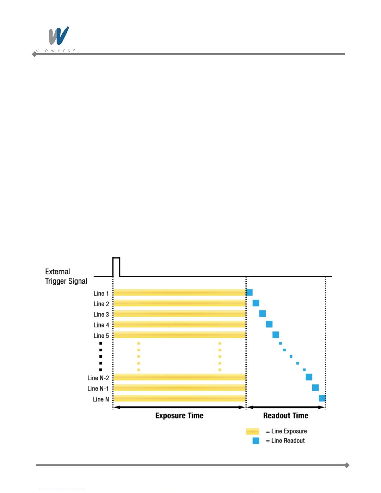
9.8.1 Global Shutter
When an exposure start trigger signal is applied to the cameras equipped with a global shutter, exposure begins
for all lines in the sensor as shown in Figure 9.13. Exposure continues for all lines in the sensor until the
programmed exposure time ends or when the exposure start trigger signal ends the exposure time if the camera
is using the trigger width exposure mode. At the end of the exposure time, exposure ends for all lines in the
sensor. Immediately after the end of exposure, pixel data readout begins and proceeds line by line until all pixel
data is read out of the sensor. A main characteristic of a global shutter is that for each frame acquisition, all of
the pixels in the sensor start exposing at the same time and all end exposing at the same time. This means that
image brightness tends to be more uniform over the entire area of each acquired image, and it helps to minimize
problems with acquiring images of object in motion.
The cameras can provide an Exposure Active output signal that will go high when the exposure time for a
frame acquisition begins and will go low when the exposure time ends.
54 of 109 RA14-133-016
Figure 9.13 Global Shutter

VQ series
9.9 Acquisition Timing Chart
Figure 9.14 shows a timing chart for frame acquisition and transmission. The chart assumes that exposure is
triggered by an externally generated exposure start trigger signal, that the Trigger Ac tivation parameter is set to
Rising Edge and that the Exposure Mode parameter is set to Timed.
As shown in the figure below, there is a slight delay between the rise of the exposure start trigger signal and the
start of exposure. After the exposure time for a frame acquisition is complete, the camera begins reading out the
acquired frame data from the imaging sensor into a frame buffer in the camera. When a sufficient amount of
frame data has accumulated in the frame buffer, the camera will begin transmitting the data to your computer.
This buffering technique avoids the need to exactly synchronize the clock used for sensor readout with the d at a
transmission. The camera will begin transmitting data when it has determined that it can safely do so without
over-running or under-running the buffer.
Exposure Start Delay: the amount of time (including trigger jitter and latency) between the point
where the trigger signal rises and the point where exposure actually begins
Frame Readout time: the amount of time it takes to read out the frame data from the imaging
sensor into the frame buffer
Frame Transmission time: the amount of time it takes to transmit an acquired frame data from the
frame buffer in the camera to your computer
Transmission Start Delay: the amount of time between the point where the camera begins rea di ng out
the acquired frame data from the sensor and the point where it begins
transmitting the acquired frame data from the buffer to your computer
Figure 9.14 Timing Chart (not drawn to scale)
55 of 109 RA14-133-016

VQ series
The following table shows Exposure Start Delay for VQ series.
Model Exposure Mode Exposure Start Delay
VQ Series
(Except VQ-310G-M400)
Timed
Trigger Width
6.2 ㎲
6.2 ㎲
106 ㎲ ≤ Delay ≤ 116 ㎲ (Trigger IN: Active High)
Timed
24 ㎲ ≤ Delay ≤ 34 ㎲ (Trigger IN: Active Low)
VQ-310G-M400
106 ㎲ ≤ Delay ≤ 116 ㎲ (Trigger IN: Active High)
Trigger Width
24 ㎲ ≤ Delay ≤ 34 ㎲ (Trigger IN: Active Low)
Table 9.4 Exposure Start Delay
The exposure must always begin on an interline boundary of the CCD sensor. For this
reason, if a trigger signal is applied during the readout process, there might be an Exposure
Start Delay up to 1 horizontal line time.
The transmission time can vary due to the characteristics of the Ethernet network.
And also, the transmission start delay can vary from frame to frame; however, it is very low significance when
compared to the transmission time.
56 of 109 RA14-133-016

VQ series
9.10 Maximum Allowed Frame Rate
In general, the maximum allowed acquisition frame rate on the camera may be limited by several factors:
The amount of time that it takes to transmit an acquired frame from the camera to your computer.
The amount of time needed to transmit a frame depends on the bandwidth assigned to the camera.
The Binning feature. If binning is enabled, the maximum allowed frame rate will increase.
The amount of time it takes to read an acquired frame out of the imaging sensor and into the camera’s
frame buffer. This time varies depending on the setting for the Height parameter. Frames with a smaller
height take less time to read out of the sensor. The frame height is determined by the camera’s Height
settings (Image Format Control).
The exposure time for acquired frames. If you use very long exposure times, you can acquire fewer frames
per second.
Decreasing the Height parameter can increase the maximum allowed frame rate; however
the Width parameter does not affect the frame rate.
When the camera's Acquisition Mode is set to Single Frame, the maximum possible
acquisition frame rate for a given ROI cannot be achieved. This is true because the camera
performs a complete internal setup cycle for each single frame and because it cannot be
operated with Trigger Overlap – Readout mode.
To achieve the maximum possible acquisition frame rate, set the Acquisition Mode
parameter to Continuous and the Trigger Overlap parameter to Readout.
57 of 109 RA14-133-016

VQ series
9.10.1 Increasing the Maximum Allowed Frame Rat e
You may find that you would like to acquire frames at a rate higher than the maximum allowed with the camera’s
current settings. In this case, you must adjust one or more of the factors that can influence the maximum allowed
frame rate and then check to see if the maximum allowed frame rate has increased:
The time that it takes to transmit a frame out of the camera is the main limiting factor on the frame rate. Y ou
can decrease the frame transmission time (and thus increase the maximum allowed frame rate) by doing
one or more of the following:
Use an 8 bit pixel data format rather than a 12 bit pixel format. Images with fewer bits per pixel will take
less time to transmit.
Use a smaller ROI. Decreasing the ROI means that the camera has less data to transmit and therefore
the transmission time will decrease.
Use binning. When pixels are binned, there is less data to transmit and therefore the transmission time
will decrease.
Make sure that the Packet Size (GevSCPSPacketSize) parameter is set as high as possible for your
system and that the Inter-Packet delay (GevSCPD) parameter is set as low as possible.
If you are using normal exposure times and you are using the camera at its maximum resolution, your
exposure time will not normally restrict the frame rate. However, if you are using long exposure times or
small region of interest, it is possible that your exposure time is limiting the maximum allowed frame rate. If
you are using a long exposure time or a small ROI, try using a shorter exposure time and see if the
maximum allowed frame rate increases. (You may need to compensate for a lower exposure time by using a
brighter light source or increasing the opening of your lens aperture.)
An important thing to keep in mind is a common mistake new camera users frequently make
when they are working with exposure time. They will often use a v ery long exposure time
without realizing that this can severely limit the camera’s maximum allowed frame rate. As an
example, assume that your camera is set to use a 1 second exposure time. In this case,
because each frame acquisition will take at least 1 second to be completed, the camera will
only be able to acquire a maximum of one frame per second. Even if the VQ-5MG-16 model’s
nominal maximum frame rate is, for example, 16 frames per second, it will only be able to
acquire one frame per second because the exposure time is set much higher than normal.
58 of 109 RA14-133-016

VQ series
10 Camera Features
10.1 Image Region of Interest
The Image Region of Interest (ROI) feature allows you to specify a portion of the sensor array. You can acquire
only the frame data from the specified portion of the sensor array while preserving the same quality as you
acquire a frame from the entire sensor array. With the ROI feature, you can achieve increased frame rates by
decreasing the height of the ROI; however, decreasing the width of the ROI does not affect the frame rate.
The ROI is referenced to the top left corner [origin (0, 0)] of the sensor array as follows.
59 of 109 RA14-133-016
Figure 10.1 Image Region of Interest

VQ series
The XML parameters related to ROI settings are as follows.
XML Parameters Value Description
SensorWidth
a
- Effective width of the sensor
SensorHeighta - Effective height of the sensor
WidthMaxb
cameras settings
Maximum allowed height of the image with the
Maximum allowed width of the image with the current
ImageFormatControl
HeightMaxb -
current camera settings
Widthc - Current width of the image
Heightc - Current height of the image
OffsetX
OffsetY
b, d
- Horizontal offset from the origin to the Image ROI
b, d
- Vertical offset from the origin to the Image ROI
The unit for all parameters in this table is pixel
a: Read only. User cannot change the value
b: Changes and updates according to the Binning settings
c: User configurable parameters for settings ROI
d: User configurable parameters for setting the origin of the ROI
Table 10.1 XML parameters related to ROI
Yo u can change the size o f ROI by setting the Width and Height parameters. And also, you can chan ge the
position of the ROI origin by setting the Offset X and Offset Y parameters.
Make sure that the Width + Offset X value is less than the Width Max val ue, a nd the Height + Offset Y value is
less than the Height Max value. You must set the si ze of the ROI f irst, and then set the Offset values since the
Width and Height parameters are set to its maximum value by default.
The Width parameter m ust be set to a multiple of 4, and the Height paramet er must be set to a val ue greater
than the minimum Vertical ROI size shown in t he
changed and updated depending on the Binning Horizontal and Binning Vertical parameter settings
respectively. And also, the Width, Height, Offset X and Offset Y parameters will be updated d epending on the
Binning Horizontal and Binning Vertical parameter settings respectively.
ROI Size updated according to the Binning settings may not be restored to its original value. For example, if you
set the Binning Horizontal parameter to
automatically. Then, if you set the Width parameter to 166 and the Binning Horizontal parameter to
Width parameter will be 498 (166 × 3). If you want to restore the Width to its original value, you can set the
Width to 500 manually.
60 of 109 RA14-133-016
table 10.2. The Width Max and Height Max parameters will be
×3 with 500 Width, the Width parameter will be updated to 166
×1, the

VQ series
VQ-310G-120†
VQ-1300G-30†
VQ-2MG-20†
VQ-5MG-16‡
The approximate maximum frame rate depending on the change of Vertical ROI can be obtained as shown in
the following expression.
1 or 2 Channel Mode:
Frame Rate (fps) = 1000000 / [T
T
: the amount of time required to transmit electric charges accumulated on
VCCD
+ TRF × (V
VCCD
SIZE
– V
) + (V
ROI
ROI
the pixels to Vertical Register
TRF : the amount of time required for 1 row flush
V
: the number of Vertical Line of CCD
SIZE
TL : the amount of time required for transmission of one line
V
: size of the Vertical ROI
ROI
The available minimum value of T
VCCD
, TRF, V
, TL and V
SIZE
may vary depending on the camera model.
ROI
The values of each item are shown below.
VQ Series
T
VCCD
TL (1 channel)
25 ㎲ 31.1 ㎲ 41.2 ㎲ 39 ㎲
16.8 ㎲ 34.4 ㎲ 40.4 ㎲
TL (2 channel) - - -
TRF
2.6 ㎲ 5.0 ㎲ 6.1 ㎲ 9.1 ㎲
× TL)]
-
30.3 ㎲
V
488 Lines 960 Lines 1232 Lines 2056 Lines
SIZE
Minimum Vertical ROI S i ze 60 Lines 120 Lines 154 Lines 256 Lines
† Based on Pixel Clock 50 ㎒ (VQ-310G-120, 1300G-30 and 2MG-20)
‡ Based on Pixel Clock 60 ㎒ (VQ-5MG-16)
Table 10.2 Timing Value for VQ Series
61 of 109 RA14-133-016

VQ series
VQ-310G-M400
In VQ-310G-M400, the approximate maximu m f r ame rate depending on the change of Vertical ROI can be
obtained as shown in the following expression.
Frame Rate (fps) = 1
/
[FOT + (TL × V
ROI
/2)]
FOT : Frame Overhead Time
TL : 1 line read time
V
: size of the Vertical ROI
ROI
VQ Series
FOT
TL
V
480 Lines
SIZE
116.7 ㎲
9.73 ㎲
Minimum Vertical ROI S i ze 2 Lines
Table 10.3 Timing Va lue for VQ-310G-M400
62 of 109 RA14-133-016

VQ series
The following figure shows frame rate for each camera model depending on Vertical ROI changes.
Figure 10.2 Frame Rate by Vertical ROI changes
63 of 109 RA14-133-016

VQ series
10.2 Binning (Except VQ-310G-M400)
Binning has the effects of increasing the level value and decreasing resolution by summing the values of the
adjacent pixels and sending them as one pixel.
The XML parameters related to Binning are as follows.
XML Parameters Value Description
BinningHorizontal
ImageFormatControl
BinningVertical
Table 10.4 XML Parameters related to Binning
For example, if you set 2 × 2 binning as shown in the figure below, four pixels will be summed into one pixel.
Then, the effective maximum resolution of the sensor is reduced to 1/2. The Width Max and Height Max
parameters, indicating the maximum allowed resolution of the image with the current camera settings, will be
updated depending on the binning sett ings . And also, the Width, Height, Offset X and Offset Y parameters will
be updated depending on the binning settings. You can verify the current resolution through the Width and
Height parameters.
Since vertical binning is processed in the internal register of CCD, the frame rate will be increased and SNR will
be improved because the number of the readout process is reduced. However, the horizontal binning does not
affect the frame rate and SNR because it is processed in the FPGA. The brightness will be increased about four
times because four pixels are summed as one.
×1, ×2, ×3, ×4
×1, ×2, ×3, ×4
Number of horizontal pixels to combine
together
Number of vertical pixels to combine
together
64 of 109 RA14-133-016
Figure 10.3 Binning

VQ series
VQ series supports ×1, ×2, ×3, ×4 binning factors for both vertical and horizontal direction independently.
Figure 10.4 Binning factor
Even if the binning is performed on the color camera, the resulting image will be
monochrome.
The odd number of binning factor (×3) does not supported on the color camera due to
the characteristics of Bayer pattern.
65 of 109 RA14-133-016

VQ series
Active Pixels
B
G
G
R
B
G
G
R
B
G
G
R
B
G
G
R
B
G
G
R
B
G
G
R
B
G
G
R
B
G
G
R
Left Dark Columns
Two Taps
Right Dark Columns
Top Dark Rows
Bottom Buffer Rows
Top Buffer Rows
Left Buffer Columns
Right Buffer Columns
One Tap
Video L Video R
Left Dummy Pixels
Rigth Dummy Pixels
Horizontal Register
Bottom Dark Rows
(1, 1)
10.3 Sensor Tap Settings
VQ-5MG-16 model uses two taps sensor digitization in which two (left and right) video amplifiers are used to
output the charges moved to the horizontal register during reading out the accumulated charges. Charges from
the left half of the sensor are shifted towards the Video L and charges from the right half of the sensor are shifted
towards Video R.
Figure 10.5 Two Taps Sensor Digitization
66 of 109 RA14-133-016

VQ series
ADC
CCD
Video L
FPGA
Image
Processing
&
Reorder
LVDS
GigE
Frame
Buffer
ADC
ADC
CCD
Video L
Video R
FPGA
Image
Processing
&
Reorder
LVDS
GigE
Frame
Buffer
LVDS
XML parameters related to Sensor Tap Settings are as follows.
XML Parameters Value Description
ImageFormatControl SensorDigitizationTaps
One Set the Sensor Readout mode to 1 tap
Two Set the Sensor Readout mode to 2 tap
Table 10.5 XML Parameter related to Sensor Tap settings
Both VQ-310G-120, VQ-1300G-30 and VQ-2MG-20 use one tap sensor digitization in which only the left video
amplifier (Video L) will be used to output the video data as shown in the Figure 10.6. VQ-5MG-16 uses two taps
sensor digitization in which both Video L and Video R will be used to output the video data as shown in the
Figure 10.7. When LVDS signals converted from the video data through ADC are transmitted to FPGA, the signal
data will be stored in the line buffer of FPGA until the transmission of one horizontal line is completed. Figure
10.9 and 10.10 show the structure which reorders and stores one line video data in the line buffer of FPGA
according to the one tap and two taps settings. In VQ-310G-M400, its CMOS image sensor performs ADC
conversion directly. As shown in the Figure 10.8, the sensor will output image data through four channels and
then FPGA will reorder image data in one line using the line buffer.
After completing one line transmission, the data goes through image processing. Then, the data will be
reordered according to the Pixel Format parameter setting value and stored in the frame buffer.
67 of 109 RA14-133-016
Figure 10.6 1Tap Image Data Flow
Figure 10.7 2Taps Image Data Flow

VQ series
CM OS
CH 1
FPG A
Image
Processing
&
Reorder
GigE
Fr a m e
Buffer
LVDS
CH 2
CH 3
CH 4
LVDS
LVDS
LVDS
14-bit
Video L(N)
1 Line Buffer
14-bit
14-bit
Video L(N+1) Video L(N+2)
14-bit
Video L
1 Line Buffer
14-bit
Video R
D11 D10 D9 D8 D7 D6 D5 D4 D3 D2 D1 D0
D11 D10 D9 D8 D7 D6 D5 D4 D3 D2 D1 D0
D12
D13
MSB LSB
Figure 10.8 VQ-310G-M400 Image Data Flow
Figure 10.9 1 Tap Reorder
Figure 10.10 2 Tap Reorder
The LVDS video data converted in ADC are 14 bits, however the camera outputs 12 bits video data. The noise
performance will be improved on the output image by removing the 2 least significant bits.
Figure 10.11 12bit Conversion
VQ-310G-120, VQ-1300G-30 and VQ-2MG-20 support only one tap sensor digitization.
VQ-5MG-16 supports only two taps sensor digitization.
68 of 109 RA14-133-016

VQ series
D11 D10 D9 D8 D7 D6 D5 D4 D3 D2 D1 D0
MSB LSB
12Bit Output
10Bit Output
8Bit Output
D9 D8 D7 D6 D5 D4 D3 D2 D1 D0
D11 D10 D9 D8 D7 D6 D5 D4 D3 D2 D1 D0
D7 D6 D5 D4 D3 D2 D1 D0
Original
Data
10.4 Pixel Format
The internal processing of image data is performed in 12 bits. Then, the camera can output the data in 8, 10 or
12 bits. When the camera outputs the image data in 8 bits or 10 bits, the 4 or 2 least significant bits will be
truncated accordingly.
Figure 10.12 Pixel Format
The image data converted to 8, 10 or 12 bits support various pixel data format depending on the camera model.
The pixel data will be reordered in FPGA according to the Pixel Format setting value. Then, it will be stored in
the frame buffer before output. XML parameter related to the Pixel Format is as follows.
XML Parameters Description
ImageFormatControl PixelFormat Set the pixel format supported by the device
Table 10.6 XML Parameter related to Pixel Format
69 of 109 RA14-133-016

VQ series
7 6 5 4 3 2 1 0
8-bit
Pixel Data
Byte 0
MSB LSB
The supported pixel formats for monochrome and color cameras are as follows.
Mono Sensor Color Sensor
Mono 8
Mono 10
Mono 10 Packed
Mono 12
Mono 12 Packed
Mono 8
Mono 10
Mono 10 Packed
Mono 12
Mono 12 Packed
Bayer BG 8
Bayer BG 10
Bayer BG 10 Packed
Bayer BG 12
Bayer BG 12 Packed
Bayer RG 8
Bayer RG 10
Bayer RG 10 Packed
Bayer RG 12
Bayer RG 12 Packed
YUV422 Packed
YUV422 (YUYV) Packed
10.4.1 Mono 8
With the camera set to Mono 8, the pixel data output is 8 bit monochrome, unsigned char and unpacked type.
This type is stored in a byte unit when 8 bit pixel data are stored in the frame buffer.
70 of 109 RA14-133-016
Table 10.7 Pixel Data Format Value
Figure 10.13 Mono 8 Format

VQ series
8-bit
2-bit
Pixel Data
Byte 1 Byte 0
LSBMSB
7 6 5 4 3 2 1 0
9 8
X X X X X X
8-bit
Pixel Data 1
Byte 2 Byte 1
LSBMSB
Byte 0
Pixel Data 0
8-bit
2-bit
9 8 7 6 5 4 3 2
1 0
9 8 7 6 5 4 3 2
2-bit
1 0
X X X X
10.4.2 Mono 10
With the camera set to Mono 10, the pixel data output is 10 bit monochrome, unsigned char and unpacked type.
This type is divided into two bytes when 10 bit pixel data are stored in the frame buffer. 8 bits of pixel data will be
stored in Byte 0, 2 bits of pixel data will be stored in Byte 1, and the rest 6 bits will not be used.
Figure 10.14 Mono 10 Format
10.4.3 Mono 10 Packed
With the camera set to Mono 10 Packed, the pixel data output is 10 bit monochrome, unsigned char and
GigE Vision-specific packed type.
This type is divided into three bytes when 20 bit pixel data are stored in the frame buffer. 8 bits of pixel data 0 will
be stored in Byte 0 and the rest 2 bits will be stored in Byte 1. Pixel Data 1 will be stored in Byte 2 and the rest 2
bits will be stored in Byte 1.
Figure 10.15 Mono 10 Packed Format
71 of 109 RA14-133-016

VQ series
8-bit
4-bit
Pixel Data
Byte 1 Byte 0
LSBMSB
7 6 5 4 3 2 1 0
11 10 9 8
X X X X
8-bit
Pixel Data 1
Byte 2 Byte 1
LSB
Byte 0
4-bit
Pixel Data 0
8-bit
4-bit
11 10 9 8 7 6 5 4
3 2 1 0 3 2 1 0
11 10 9 8 7 6 5 4
10.4.4 Mono 12
With the camera set to Mono 12, the pixel data output is 12 bit monochrome, unsigned and unpacked type.
This type is divided into two bytes when 12 bit pixel data are stored in the frame buffer. 8 bits of pixel data will be
stored in Byte 0 and the rest 4 bits will be stored in Byte 1. The rest 4 bits of Byte 1 will not be used.
Figure 10.16 Mono 12 Format
10.4.5 Mono 12 Packed
With the camera set to Mono 12 Packed, the pixel data output is 12 bit monochrome, unsigned and
GigE Vision-specific packed type.
This type will be divided into three bytes when 24 bit pixel data are stored in the frame buffer.
8 bits of pixel data 0 will be stored in Byte 0 and the rest 4 bits will be stored in Byte 1. 8 bits of pixel data 1 will
be stored in Byte 2 and the rest 4 bits will be stored in Byte 1.
Figure 10.17 Mono 12 Packed Format
72 of 109 RA14-133-016

VQ series
8-bit
Pixel Data (2,1)-Red
Byte 2 Byte 1
LSBMSB
Byte 0
2-bit
Pixel Data (1,1)-Green
8-bit
2-bit
9 8 7 6 5 4 3 2
X X 1 0 X X 1 0
9 8 7 6 5 4 3 2
8-bit
Byte 2 Byte 1
LSBMSB
Byte 0
2-bit8-bit
2-bit
9 8 7 6 5 4 3 2
X X 1 0 X X 1 0
9 8 7 6 5 4 3 2
Horizontal
Direction
Vertical
Direction
1-Line
2-Line
Pixel Data (0,1)-Green Pixel Data (1,2)-Blue
10.4.6 Bayer Formats
When you set the Pixel Format parameter to any Bayer Format in the color camera, the bits of pixel data will
be reordered to bytes, and then will be stored in the frame buffer in the same way as Mono Format.
For example, if you set the Pixel Format parameter to Bayer GR 10 Packed, the pixel data will be reordered
and stored in the frame buffer as shown in the Figure 10.17. 10 least significant bits of green data will be stored
in Byte 0 and Byte 1, and 10 most significant bits of red data will be stored in Byte 2 and Byte 1. The bit order is
shown in the first figure below. After saving 1 - horizontal line of G-R pattern pixel data, 2 – horizontal line of B-G
pattern pixel data will be stored as shown in the second figure below. G-R pattern (Horizontal Direction) and B-G
pattern (Horizontal Direction) pixel data will be stored repeatedly as a line (Vertical Direction).
73 of 109 RA14-133-016
Figure 10.18 Bayer Format

VQ series
10.4.7 YUV Formats
All VQ color cameras except VQ-5MG-16 can output pixel data in YUV422 Packed format or in YUV422 (YUYV)
Packed format. When a color camera is set for either of these formats, each pixel in the acquired image goes
through a two step conversion process. In the first step of the process, a demosaicing algorithm is performed to
get RGB data for each pixel. The second step of the process is to convert the RGB information to the YUV color
model. The conversion algorithm uses the following formulas:
Y = 0.299 R + 0.587 G + 0.114 B
U = -0.169 R - 0.331 G + 0.499 B
V = 0.499 R - 0.418 G - 0.0813 B
The values for U and V normally range from -128 to +127. Because the camera transfers U
and V values with unsigned integers, 128 is added to eac h U and V value befor e the values
are transferred from the camera. This process allows the values to be transferred on a scale
that ranges from 0 to 255.
74 of 109 RA14-133-016

VQ series
1
2
3
4
5
2
6
2
7
3
8
9
4
10
4
n-3
m-1
n-2
m-1
n-1
m-1
YUV422 Packed
The following table shows how the pixel data for an acquired frame will be ordered in the image buffer in your
computer when the Pixel Format parameter is set to YUV422 Packed on a color camera.
B
B
P
P
= the first byte in the buffer
0
= the last byte in the buffer
n
= the first pixel transmitted by the camera
0
= the last pixel transmitted by the camera
m
Byte Data
B
0
B
Y value for P0
B
V value for P0
B
Y value for P1
B
U value for P2
B
Y value for P
B
V value for P
B
Y value for P
B
U value for P4
B
Y value for P
U value for P
0
B
V value for P
• •
• •
• •
B
U value for P
B
Y value for P
B
V value for P
Bn Y value for Pm
Table 10.8 YUV422 Packed Format
75 of 109 RA14-133-016

VQ series
1
2
3
4
5
2
6
3
7
2
8
9
4
10
5
4
n-3
m-1
n-2
m-1
n-1
m-1
YUV422 (YUYV) Packed
The following table shows how the pixel data for an acquired frame will be ordered in the image buffer in your
computer when the Pixel Format parameter is set to YUV422 (YUYV) Packed on a color camera.
B
B
P
P
= the first byte in the buffer
0
= the last byte in the buffer
n
= the first pixel transmitted by the camera
0
= the last pixel transmitted by the camera
m
Byte Data
B
0
B
U value for P0
B
Y value for P1
B
V value for P0
B
Y value for P2
B
U value for P
B
Y value for P
B
V value for P
B
Y value for P4
B
U value for P
Y value for P
0
B
Y value for P
B11 V value for P
• •
• •
• •
B
Y value for P
B
U value for P
B
Y value for Pm
Bn V value for P
Table 10.9 YUV422 (YUYV) Packed Format
76 of 109 RA14-133-016

VQ series
10.5 Stream Hold
VQ camera provides Stream Hold feature for controlling the transmission of data.
Normally, the camera transmits frame data to the host computer immediately after completing the exposure.
Enabling the Stream Hold feature delays the transmission of data, storing it in the camera’s volatile memory
until the Stream Hold feature is disabled.
This feature is especially useful to prevent flooding in Gigabit Ethernet network where multiple cameras are
connected to a single host computer and capture a single event. Using the Stream Hold feature, each camera
will hold the image data until the camera’s Stream Hold feature is disabled. VQ camera provides 64 MB onboard memory for the Stream Hold feature. The Stream Hold feature does not allow you to select which frame
will be released to the host computer. When the Stream Hold feature is disabled, the stored frame data will be
released to the host computer. For more information, refer to the application note about stream hold.
XML Parameters Value Description
TransportLayerControl
On
StreamHold
Off Release the stored frame data to the host computer.
FrameCapacity -
Table 10.10 XML Parameters related to Stream Hold feature
Delay the transmission of frame data and store them
in the frame buffer.
Display the maximum number of frames that you
can store in the frame buffer
The maximum number of frames will vary
depending on the Image ROI and pixel format
settings.
With the Stream Hold feature set to On, the
newly acquired frame will be ignored after saving
the maximum number of frames.
77 of 109 RA14-133-016

VQ series
10.6 Inter-Packet Delay
VQ camera provides the Inter-packet delay feature to set the delay in ticks between the packets transmitted by
the camera.
Packet Size
The GevSCPSPacketSize parameter sets the size of the packets that the camera will use when it sends the
data via the selected stream channel. This parameter should always be set to the maximum size that your
network components (Ethernet Adapter) can handle.
Setting the Delay between Packets
The GevSCPD parameter sets the delay in ticks between the packets transmitted from the camera. Increasing
the delay will decrease the camera’s effective data transmission rate and will thus decrease the network
bandwidth used by the camera.
In the VQ camera, one tick is 8 ㎱. To check the tick frequency, read the GevTimestampTickFrequency
parameter value.
In case of multiple cameras or other devices working on the same physical network, it might be desirable to send
the packets of a camera’s streaming channel with a certain inter-packet delay in order to allow multiple cameras
or devices to share a given network bandwidth.
XML Parameters Value Description
Set the packet size (The maximum
TransportLayerControl
GevSCPSPacketSize 576~16,000 Bytes
GevSCPD 0~ 2141483647
Table 10.11 XML Parameters related to Inter-Packet Delay
value may vary depending on the
Ethernet Adapter.).
Set the delay in ticks
(one tick = 8 ㎱) between packets.
78 of 109 RA14-133-016

VQ series
10.7 Data ROI
The Exposure Auto (Except VQ-5MG-16) and Balance White Auto features use the pixel data from a Data
Region of Interest (ROI) to adjust the related parameters.
XML parameters related to data ROI are as follows.
XML Parameters Value Description
AE Select a Data ROI used for Auto Exposure
RoiSelector
DataRoiControl
RoiOffsetX - X coordinate of start point ROI
RoiOffsetY - Y coordinate of start point ROI
RoiWidth - Width of ROI
RoiHeight - Height of ROI
Table 10.12 XML Parameters related to Data ROI
All models except VQ-5MG-16
AWB Select a Data ROI used for Auto White Balance
Only available on color cameras
79 of 109 RA14-133-016

VQ series
Only the pixel data from the area of overlap between the data ROI by your settings and the Image ROI will be
effective if you use Image ROI and Data ROI at the same time. The effective ROI is determined as shown in the
figure below.
80 of 109 RA14-133-016
Figure 10.19 Effective Data ROI

VQ series
10.8 Exposure Auto and Gain Auto (Except VQ-5MG-16)
The Exposure Auto feature automatically adjusts the Exposure Time parameter until the grey level for the
pixels in the given Data ROI reaches an Exposure Auto Target Level value set by the user.
The Exposure Auto feature in VQ GigE series uses iterative algorithm which repeatedly calculates the previous
exposure values until it gets new exposure value. Note that the camera needs up to 30 frames to complete the
Exposure Auto feature.
The Exposure Auto feature is not available if the Exposure Mode parameter is set to
Trigger Width.
The Exposure Auto and Gain Auto features can be used at the same time and operated in the Off, Once and
Continuous modes of operation. If you use two features at the same time, the camera will adjust the value of
Exposure Time followed by Digital Gain.
When the Exposure Auto or Gain Auto feature is set to Once, the parameter values are automatically adjusted
until the related parameter value reaches the target value. After the automatic parameter value adjustment is
complete, the feature will be set to Off. When the auto feature is set to Continuous, the camera adjusts
Exposure Time or Digital Gain parameter to reach the target value every time the lighting conditions change.
You can set the Exposure Auto Tolerance parameter to adjust the sensitivity of the Exposure Auto feature.
Figure 10.20 Exposure Auto Target Level and Exposure Auto Tol er anc e
81 of 109 RA14-133-016

VQ series
Each auto feature has the following operating ranges depending on the object brightness level. You can set the
operating range by adjusting the minimum and maximum value for each feature.
Figure 10.21 Image Level Adjustment
When the Exposure Auto or Gain Auto parameter is set to Off, the operating procedures are as follows.
Auto Features
Operating Procedures Remarks
Exposure Gain
Both the Exposure and Gain are adjusted
On On Exposure Gain
automatically
On Off Exposure Manually adjustable the Gain
Off On Gain Manually adjustable the Exposure
Manually adjustable both the Exposure and
Off Off -
Gain
Table 10.13 Operating Pro cedures for Auto Features
82 of 109 RA14-133-016

VQ series
XML parameters related to AEC (Auto Exposure Control) are as follows.
XML Parameters Value Description
Off Exposure Auto Off
AcquisitionControl
AnalogControl
ExposureAuto
ExposureAutoMin
ExposureAutoMax
ExposureAutoTargetLevel 100~3995
ExposureAutoTolerance 100~2047
GainAuto
Once
Continuous Target Level is constantly adapted
Refer to Table
9.1
~7,000,000 ㎲
Off Gain Auto Off
Once Gain is adjusted once and then Off
Continuous Gain is constantly adjusted
Target Level is adapted once and then
Off
Lower limits of Exposure duration
(The lower the value, the more smear)
Upper limits of Exposure duration
(The higher the value, the more motion
blur)
Target average grey value (12bit†)
Tolerance of the target average grey
value - 12 bit (If the current grey level is
out of the tolerance, AEC starts to work.)
GainAutoMin
GainAutoMax Upper limits of Gain
Table 10.14 XML Parameters related to AEC
You can set the Exposure Auto and Gain Auto feature in any order. However, we
strongly recommend setting the one feature first while turning off the other features for
the smooth operation.
†: The maximum allowed Exposure Auto T arget Level value may vary depending on the
83 of 109 RA14-133-016
Exposure Auto Tolerance setting value.
Exposure Auto Target Level = (0+Tolerance) ~ (4,095 –Tolerance)
×1~×64
Lower limits of Gain

VQ series
10.9 Balance White Auto (Color Cameras)
The Balance White Auto feature is implemented on color cameras. It will control the white balance of the image
acquired from the color camera according to the GeryWorld algorithm. Before using the Balance White Auto
feature, you need to set the Data ROI for Balance White Auto. If you do not set the related Data ROI, the pixel
data from the Image ROI will be used to control the white balance. As soon as the Balance White Auto
parameter is set to Once, the Digital Red, Digital Green and Digital Blue will be set to 1. Then, Digital Red and
Digital Blue will be adjusted to control the white balance.
XML parameters related to the Balance White Auto and RGB Gain settings are as follows.
XML Parameters Value Description
AnalogAll Apply gain to all analog taps
DigitalAll Apply gain to all digital channels
AnalogControl
GainSelector
Gain
BalanceWhiteAuto
Table 10.15 XML Parameters related to Balance Whi te Auto
DigitalRed Apply gain to red digital channel
DigitalGreen Apply gain to green digit al c hanne l
DigitalBlue Apply gain to blue digital channel
Set an absolute physical gain value when Digital
×0.5 ~ ×2.0
Red, Green or Blue is selected
Off Balance White Auto Off
Once White Balance is adjusted once and then Off
84 of 109 RA14-133-016

VQ series
CDS
GAIN
VGA
GAIN
ANALOG
CCD IN
LEVEL
CLAMP
14-BIT
LVDS
1~40 times
14-BIT
ADC
10.10 Gain and Black Level
You can set the analog (VGA) and digital gain factor to adjust the gain. The black level is adjusted by removing
the optical black offset from the CCD so that the effect of dark current will be minimized.
10.10.1 Analog Domain
The VQ camera has one Analog Signal Processor (or Analog Front End (AFE)) for each channel. This AFE
consists of Correlated Double Sampler (CDS), Variable Gain Amplifier (VGA), Black Level Clamp and 14-bit A/D
converter.
You can change the gain and black level value by inputting proper value into the registers for gain and black
level adjustments inside the AFE. The CDS gain value is set in the factory during the manufacturing process,
therefore you cannot change the value. The VGA gain is the same as the analog gain.
On VQ-5MG-16 model, you can set the analog gain for all analog taps or each tap. You can determine whether
to control the gain balance between each tap manually or automatically by setting the Gain Auto Balance
parameter to Off or Once. To balance the black level between each tap, use the Black Level parameter.
In VQ-310G-M400, you can change the gain and black level value by inputting proper value into the registers for
gain and black level adjustments inside CMOS sensor.
85 of 109 RA14-133-016
Figure 10.22 AFE Block Diagram

VQ series
10.10.2 Digital Domain
Digital gain is adjustable from 1 to ×64 with almost 1/1024 step. If the Gain Auto parameter is set to Once or
Continuous, the digital gain value will be automatically adjusted according to the Exposure Auto Target Level
parameter settings. XML parameters related to Gain and Black Level are as follows.
XML Parameters Value Description
AnalogAll Apply gain to all analog taps
DigitalAll Apply gain to all digital channels
AnalogControl
GainSelector
Gain -
GainAuto
BlackLevelSelector All Apply black level to all taps
BlackLevel 0~255
Table 10.16 XML Parameters related to Gain and Black Level
DigitalRed Apply gain to red digital channel
DigitalGreen Appl y gain to green di git al channe l
DigitalBlue Apply gain to blue digital channel
Set an absolute physical gain value
Analog All: ×1.0~×40 (Except VQ-310G-M400)
Analog All: ×1.0~×3.5 (VQ-310G-M400)
Digital All: ×1.0~×64
Off Gain Auto Off
Once Gain value is adjusted once and then Off
Continuous Gain value is constantly adjusted
Set an absolute physical black level value.
(0 ~ 127 LSB @ 12bit, Except VQ-310G-M400)
Set an absolute physical black level value.
(0 ~ 256 LSB @ 12bit, VQ-310G-M400)
86 of 109 RA14-133-016

VQ series
12-bit Data
4096 entry
Lookup Table
12-bit Data
LUT
0
500
1000
1500
2000
2500
3000
3500
4000
0 500 1000 1500 2000 2500 3000 3500 4000
Input Level
Output Level
10.11 LUT (Except VQ-5MG-16)
Lookup T able (LUT) converts original image values to certain level values.
Luminance
Since it is mapped one to one for each level value, 12-bit output can be connected to 12-bit input. LUT is in the
form of table that has 4096 entries between 0~4095 and VQ camera provides a non-volatile space for LUT data
storage. You can determine whether to apply LUT. For more information about how to download LUT to the
camera, refer to
Appendix B.
Figure 10.23 LUT Block
87 of 109 RA14-133-016
Figure 10.24 LUT at Gamma 0.5

VQ series
XML parameters related to LUT are as follows.
XML Parameters Value Description
LUTSelector Luminance Luminance LUT
LUTControl
LUTEnable
On Activate the selected LUT
Off Deactivate the selected LUT
Index of coefficient for verifying the LUT Value
LUTIndex -
Luminance: 0 ~ 4095
Output value of the current LUT corresponding to the input value
LUTValue -
of LUT Index
Table 10.17 XML Parameters related to LUT
The LUT feature does not supported on the VQ-5MG-16 model.
88 of 109 RA14-133-016

VQ series
L3
L2 L1
R1
R2 R3
<Current Pixel>
10.12 Defective Pixel Correction
The CCD may have defective pixels which cannot properly react to the light. Correction is required since it may
deteriorate the quality of output image. Defective pixel information of CCD used for each camera is entered into
the camera during the manufacturing process in the factory. If you want to add defective pixel inform ation , it is
required to enter coordinate of new defective pixel into the camera.
10.12.1 Correction Method
Correction value for a defective pixel is calculated based on valid pixel value adjacent in the same line.
Figure 10.25 Location of Defective Pixel to Be Corrected
If current pixel is a defective pixel as shown in the above figure, correction value for this pixel is obtained as
shown in the following table depending on whether surrounding pixel is defective pixel or not.
Adjacent Defective Pixel(s) Correction Value of Current Pixel
None (L1 + R1) / 2
L1 R1
R1 L1
L1, R1 (L2 + R2 ) / 2
L1, R1, R2 L2
L2, L1, R1 R2
L2, L1, R1, R2 (L3 + R3) / 2
L2, L1, R1, R2, R3 L3
L3, L2, L1, R1, R2 R3
Table 10.18 Calculation of Defective Pixel Correction Value
89 of 109 RA14-133-016

VQ series
10.12.2 Correction Method in Binning Mode (Except VQ-310G-M400)
The Defective Pixel Correction feature is also available even when 2×2 or 4×4 binning is enabled.
The correction value will be averaged based on four neighboring pixels during 2×2 binning and sixteen
neighboring pixels during 4×4 binning.
XML parameter related to Defective Pixel Correction is as follows.
XML Parameters Value Description
ImageFormatControl DefectivePixelCorrection
Table 10.19 XML Parameter related to Defective Pixel Correction
To apply the Defective Pixel Correction feature, you must download a Defective Pixel Map
to the camera. For more information about how to download a Defective Pixel Map to the
camera, refer to
Appendix A.
On
Apply a downloaded defective pixel map to
the camera
Disable the application of the defective pixel
Off
map
90 of 109 RA14-133-016

VQ series
10.13 Temperature Monitor
A sensor chip is embedded in the camera to monitor the internal temperature.
XML parameter related to Device Temperature is as follows.
XML Parameters Description
DeviceControl DeviceTemperature Display device temperature in Celsius
Table 10.20 XML Parameter related to Device Temperature
10.14 Status LED
A green LED is installed on the back panel of the camera to inform the operation status of the camera. LED
status and corresponding camera status are as follows:
Continuous ON: The camera operates in Trigger Off mode.
Repeat ON for 0.5 seconds, OFF for 0.5 seconds: The camera operates in Trigger mode.
Repeat ON for 1 second, OFF for 1 second: The camera outputs Test Image.
Repeat ON for 0.25 second, OFF for 0.25 second: The camera operates in Trigger mode and outputs Test
Image.
VQ-310G-M400’s LED status and corresponding camera status are as follows:
LED Off: The camera is powered off. No power to the camera.
Steady Red: The camera is not initialized.
Slow Flashing Orange: The camera is checking IP address.
Fast Flashing Orange: Ethernet cable is disconnected.
Steady Orange: IP address is assigned; The camera is not connected
to any applications.
Steady Green: The camera is connected to an application.
Slow Flashing Green: The camera is acquiring images with the Trigger Mode
set to ON.
Fast Flashing Green: The camera is acquiring images in the free run mode.
91 of 109 RA14-133-016

VQ series
10.15 Test Image
To check whether the camera operates normally or not, it can be set to output test images generated in the
camera, instead of the image data from the CCD. Three types of test images are available; im age with different
value in horizontal direction (Grey Horizontal Ramp), image with different value in diagonal direction (Grey
Diagonal Ramp), and moving image with different value in diagonal direction (Grey Diagonal Ramp Moving).
XML parameters related to Test Image are as follows.
XML Parameters Value Description
Off Test Image Off
GreyHorizontalRamp Set to Grey Horizontal Ramp
ImageFormatControl TestImageSelector
Table 10.21 XML Parameter related to Test Image
GreyDiagonalRamp Set to Grey Diagonal Ramp
GreyDiagonalRampMoving Set to Grey Diagonal Ramp
Moving
92 of 109 RA14-133-016
Figure 10.26 Grey Horizontal Ramp

VQ series
Figure 10.27 Grey Diagonal Ramp
Figure 10.28 Grey Diagonal Ramp Moving
The test image may look different because the region of the test image may vary depending
on the camera’s resolution.
93 of 109 RA14-133-016

VQ series
10.16 Digital IO Control
The pin number 4 of the Power Input and Control I/O Receptacle is designated as programmable output and can
be operated in various modes.
XML parameters related to Digital IO Control are as follows.
XML Parameters Value Description
DigitalIO
Control
LineInverter
LineSource
UserOutputValue
PulsePeriod
PulseWidth
StrobeOutDelay
On Enable inversion on the output signal of the line
Off Disable inversion on the output signal of the line
Off
ExposureActive
FrameActive
StrobeOut
PulseGenerator
UserOutput Output User Output signal set by User Output Value
On Set the bit state of the line to High
Off Set the bit state of the line to Low
1~60,000,000 Set a pulse period in microseconds when the Line Source
0~60,000,000 Set a pulse width in microseconds when the Line Source
0~65535 Set a delay in microseconds when the Line Source is set
Disable the line output
Output pulse signals indicating the current exposure time
Output pulse signals indicating a frame readout time
Output Exposure Active signals with Strobe Out Delay
Output user defined pulse signals
is set to Pulse Generator
is set to Pulse Generator
to Strobe Out
94 of 109 RA14-133-016
Table 10.22 Digital I O Contro l

VQ series
The camera can provide an Exposure Active output signal. The signal goes high when the exposure time for
each frame acquisition begins and goes low when the exposure time ends as shown in Figure 10.28. This signal
can be used as a flash trigger and is also useful when you are operating a system where either the camera or
the object being imaged is movable. Typically, you do not want the camera to move during exposure. You can
monitor the Exposure Active signal to know when exposure is taking place and thus know when to avoid
moving the camera.
Figure 10.29 Exposure Active Signal
When you use the Exposure Active signal, be aware that there is an Exposure Active Delay
between the point where exposure actually begins and the point where the signal rises. See
Figure 10.29 and Table 10.23.
Model Exposure Active Delay
VQ series
VQ-310G-M400
Table 10.23 Exposure Active Delay
68 ㎲
Active High: 106 ㎲
Active Low: 24 ㎲
95 of 109 RA14-133-016

VQ series
10.17 Event Control
VQ camera provides an Event Notification feature. With the Event Notification feature, the camera can generate
an event and transmit a related event message to the PC whenever a specific situation has occurred.
The camera can generate and transmit events for the following type of situation:
The end of an exposure has occurred (Exposure End)
XML parameters related to Event Control are as follows.
XML Parameters Value Description
EventControl
TransportLayer
Control
EventSelector ExposureEnd
On Enable the selected event notification
Event Notification
Off Disable the selected event notification
GevTimestampControlLatch -
GevTimestampControlReset - Reset the time stamp counter to 0.
Table 10.24 XML Parameters related to Event Control
Select which particular event to control
Exposure End event is only available
Latch the current time stamp counter into
GevTimestampValue.
96 of 109 RA14-133-016

VQ series
10.18 Device User ID
You can input user defined information up to 16 bytes.
XML parameter related to Device User ID is as follows.
XML Parameters Description
DeviceControl DeviceUserID Input user defined information (16 bytes)
Table 10.25 XML Parameter related to Device User ID
10.19 Device Reset
Reset the camera physically to power off and on. You must connect to the network because the camera will be
released from the network after reset. XML parameter related to Device Reset is as follows.
XML Parameters Description
DeviceControl DeviceReset Reset the camera physically
Table 10.26 XML Parameter related to Device Reset
97 of 109 RA14-133-016

VQ series
10.20 User Set Control
You can save the current camera settings to the camera’s internal ROM. You can also load the camera settings
from the camera’s internal ROM. The camera provides two setups to save and three setups to load settings.
XML parameters related to User Set Control are as follows.
XML Parameters Value Description
Default Select the Factory Default settings
UserSetSelector
UserSetLoad -
UserSetControl
UserSetSave -
UserSetDefaultSelector
Table 10.27 XML Parameters related to User Set Control
UserSet1 Select the User Set1 settings
UserSet2 Select the User Set2 settings
Load the User Set specifie d by User Set Selector
to the camera
Save the current settings to the User Set specified
by User Set Selector
Default is allowed to load only.
Default Apply the Factory Default settings when reset
UserSet1 Apply the User Set1 settings when reset
UserSet2 Apply the User Set2 settings when reset
10.21 Field Upgrade
The camera provides a feature to upgrade Firmware and FGPA logic through Gigabit Ethernet interface rather
than disassemble the camera in the field. Refer to
Appendix C for more details on how to upgrade.
98 of 109 RA14-133-016

VQ series
Appendix A Defective Pixel Map Download
1. Create the Defective Pixel Map data in Microsoft Excel format as shown in the left picture below and save
as a CSV file (*.csv). The picture in the right shows the created Excel file opened in Notepad. The following
rules need to be applied when creating the file.
Lines beginning with ‘:’ or ‘—’ are treated as notes.
Each row is produced in the order of the horizontal and vertical coordinate values.
The input sequence of pixel is irrelevant.
2. Run Vieworks Imaging Solution 6.X and click the Configure button to display the window as shown below.
Select the Defect tab, click the File Path button, search and select the defective pixel map file (*.csv), and
then click the Download button.
99 of 109 RA14-133-016

VQ series
3. Once the do wnlo ad is complet e, the saving process will begin. During the saving process, make sure not to
disconnect the power cord.
4. After completing the download, click the OK button to close the confirmation.
100 of 109 RA14-133-016
 Loading...