

Page 1
ATTRACT, DISPLAY, INFORM
OPERATION
MANUAL
VM042H/VM032
Page 1
PROFESSIONAL LCD DISPLAY SIGNAGE
Page 2

WARNING
OWNER’S RECORD
The model and serial numbers are located on the rear of the unit. Record the model and serial numbers in the
spaces provided below for record purposes. Refer to these numbers whenever you call your local dealer
regarding this product.
Model Number: Serial Number:
To reduce the risk of fire or electric shock, do not expose this apparatus
to rain or moisture.
To avoid electrical shock, do not open the cabinet. Refer servicing to
qualified personnel only.
On Transportation
Hold the unit itself and not the speakers (if applicable) when you carry the display unit. Failing to do so may
result in dropping the unit and causing serious damage and/or injury.
For customers in the U.S.A.
If you have any questions about this product, you may call Viewmax Corporation’s Customer Service
Center 1-800-000-0000 or http://www.ati-eng.com.
Declaration of Conformity
Trade Name: Viewmax Corporation Ltd.
Model: VM042(H)
Responsible Party: Viewmax Corporation Ltd.
Address: 1214, Sicox Tower,
513-14, Sangdaewon-Dong, Jungwon-Gu,
This device complies with Part 15 of the FCC Rules. Operation is subject to the following conditions: (1) This
device may not cause harmful interference, and (2) this device must accept any interference received, including
interference that may cause undesired operation.
This equipment has been tested and found to comply with the limits for a Class B digital device, pursuant to Part
15 of the FCC Rules. These limits are designed to provide reasonable protection against harmful interference in
a residential installation. This equipment generates, uses, and can radiate radio frequency energy and, if not
installed and used in accordance with the instructions, may cause harmful interference to radio communications.
However, there is no guarantee that interference will not occur in a particular installation. If this equipment does
cause harmful interference to radio or television receptions, which can be determined by turning the equipment
off and on, the user is encouraged to try to correct the interference by one or more of the following measures:
Reorient or relocate the receiving antenna.
Increase the separation between the equipment and receiver.
Connect the equipment into an outlet on a circuit different from that to which the receiver is connected.
Consult the dealer on an experienced radio/TV technician for help.
You are cautioned that any changes or modifications not expressly approved in this manual could void your
authority to operate this equipment.
Page 2
Page 3

TABLE OF CONTENTS
P
RREECCAAUUTTIIOONNS
P
General Safety Guide...........................................................................................................................7
Installation................................................................................................................................................. 7
Cleaning.................................................................................................................................................... 7
Notes on Handling and Cleaning the Display Panel................................................................................. 7
Repacking................................................................................................................................................. 7
L
OOCCAATTIIOONNSS AANNDD
L
Front / Rear / Side / Bottom Views......................................................................................................8
X Indicator and OSD Control Buttons ...................................................................................................... 8
Y Computer Access Panel.......................................................................................................................8
Z Wall Mount Installation Holes ............................................................................................................... 8
[ Connector Panel Cover ........................................................................................................................ 8
Control Button Section (Side).............................................................................................................9
X Power Button.................................................................................................................................... 9
Y Menu Button ......................................................................................................................................... 9
Z Select Button ........................................................................................................................................ 9
[ \ ©/ª Up/Down Buttons.....................................................................................................................9
] Power and Standby Indicator Light ......................................................................................................9
^ Rubber Plug.......................................................................................................................................... 9
Remote Control (Optional) ................................................................................................................10
iMON Pad Controller............................................................................................................................... 10
Using iMEDIAN.......................................................................................................................................12
Connector Panel.................................................................................................................................13
X Mouse PS/2 Connector ......................................................................................................................13
Y Keyboard PS/2 Connector.................................................................................................................. 13
Z DVI Port .............................................................................................................................................. 13
[ USB Ports...........................................................................................................................................13
\ Audio Connection Port........................................................................................................................ 13
] LAN Port ............................................................................................................................................. 13
^ VGA Port ............................................................................................................................................14
S
.....................................................................................................
F
UUNNCCTTIIOONN OOFF
F
C
OONNTTRROOLLS
C
S
.....................................................................................................
.....................................................................................................
.......................88
....7
7
I
NNSSTTAALLLLAATTIIOON
I
Before you start..................................................................................................................................15
Installation Precautions........................................................................................................................... 15
Preinstalled Components........................................................................................................................ 15
Installation and Configuration Steps................................................................................................15
Unpacking...............................................................................................................................................15
Packing List ............................................................................................................................................ 16
Mounting Space Requirements.........................................................................................................16
Mounting the Display Horizontally ..........................................................................................................17
Mounting the Display Vertically ..............................................................................................................17
Using the Optional Stand (not supplied)................................................................................................. 17
Mounting the System.........................................................................................................................18
Wall Mounting ......................................................................................................................................... 18
Using the Monitor Stand (Optional) ........................................................................................................ 21
Connecting the AC Power Cord........................................................................................................22
Connecting the Speakers (Optional)................................................................................................22
U
SSIINNGG
U
Operating OSD Menus.......................................................................................................................23
N
O
N
O
Menu operating buttons .......................................................................................................................... 23
Configuration of the Menu ......................................................................................................................23
N
S
CCRREEEEN
--S
M
OOUUNNTTIINNGG
//M
N
--D
D
IISSPPLLAAYY
G
G
E
UUIIDDE
.....................................................................................................
((OOSSDD)
)
M
M
S
EENNUUS
.....................................................................................................
...............................................1155
.............2233
Page 3
Page 4

Menu Guide.........................................................................................................................................24
Color Mode..........................................................................................................................................24
Contrast ..................................................................................................................................................24
Brightness...............................................................................................................................................24
Color Adjust ............................................................................................................................................ 24
Color Temperature.................................................................................................................................. 24
Image Setting......................................................................................................................................25
Clock ....................................................................................................................................................... 25
Phase...................................................................................................................................................... 25
Gamma ................................................................................................................................................... 25
Sharpness............................................................................................................................................... 25
Position...............................................................................................................................................26
H. Position............................................................................................................................................... 26
V. Position............................................................................................................................................... 26
Fit to Screen ........................................................................................................................................... 26
OSD Menu...........................................................................................................................................26
OSD H. Position...................................................................................................................................... 26
OSD V. Position......................................................................................................................................26
OSD Timer..............................................................................................................................................27
Language ............................................................................................................................................27
Miscellaneous.....................................................................................................................................27
Signal Source .........................................................................................................................................28
Volume.................................................................................................................................................... 28
Mute ........................................................................................................................................................ 28
Reset....................................................................................................................................................... 28
S
PPEECCIIFFIICCAATTIIOONNS
S
System Specifications.......................................................................................................................29
Mainboard Specifications ..................................................................................................................29
Flat Panel Screen Specifications......................................................................................................29
M
AAIINNBBOOAARRD
M
Introduction ........................................................................................................................................30
CPU......................................................................................................................................................30
On-Board Chipset...............................................................................................................................30
Peripheral Device Interfaces, Connectors and Slots......................................................................31
Internal Slots...........................................................................................................................................31
Internal Peripheral Device Connectors...................................................................................................32
External Peripheral Device Connectors.................................................................................................. 32
S
YYSSTTEEMM
S
System Maintenance Introduction ....................................................................................................33
Mainboard Replacement ....................................................................................................................33
Mainboard Access Panel Removal...................................................................................................33
Component Replacements................................................................................................................36
M
M
Mainboard Access Panel Removal......................................................................................................... 34
Rear Panel Removal............................................................................................................................... 35
Hark Disk Drive Replacement................................................................................................................. 36
Memory Module Replacement................................................................................................................ 36
DVD Drive Replacement......................................................................................................................... 37
S
.....................................................................................................
D
.....................................................................................................
AAIINNTTEENNAANNCCE
E
.....................................................................................................
...............................................................................................2299
.....................................................................................................
.........................................................................3333
......330
0
S
S
BBIIOOS
Entering Setup....................................................................................................................................39
S
P
EETTUUP
Control Keys ........................................................................................................................................... 39
.....................................................................................................
Page 4
.....................................................................................................
..339
9
Page 5

Getting Help............................................................................................................................................39
Main Menu .............................................................................................................................................. 39
Sub-Menu ............................................................................................................................................... 39
General Help <F1> ................................................................................................................................. 39
The Main Menu ...................................................................................................................................40
Standard CMOS Features..................................................................................................................41
Date (MM:DD:YY)...................................................................................................................................41
Time (HH:MM:SS) ..................................................................................................................................41
IDE Primary Master/Slave, SATA 1~4.................................................................................................... 41
Device / Vendor / Size ............................................................................................................................ 42
LBA/Large Mode.....................................................................................................................................42
DMA Mode..............................................................................................................................................42
Hard Disk S.M.A.R.T. .............................................................................................................................42
Floppy A.................................................................................................................................................. 42
System Information.................................................................................................................................42
Advanced BIOS Features ..................................................................................................................43
Boot Sector Protection............................................................................................................................43
Full Screen LOGO Display ..................................................................................................................... 43
Quick Booting .........................................................................................................................................43
Boot Up Num-Lock LED .........................................................................................................................43
IOAPIC Function.....................................................................................................................................43
MPS Table Version.................................................................................................................................43
CPU Feature...........................................................................................................................................44
Chipset Feature ...................................................................................................................................... 44
Boot Sequence .......................................................................................................................................44
Trusted Computing .................................................................................................................................45
Integrated Peripherals .......................................................................................................................45
USB Controller........................................................................................................................................45
USB Device Legacy Support .................................................................................................................. 45
Onboard LAN Controller ......................................................................................................................... 46
LAN Option ROM....................................................................................................................................46
Audio Controller ...................................................................................................................................... 46
On-Chip ATA Devices............................................................................................................................. 46
I/O Devices ............................................................................................................................................. 46
Power Management Setup.................................................................................................................47
ACPI Function......................................................................................................................................... 47
ACPI Standby State................................................................................................................................47
Suspend Time Out (Minute).................................................................................................................... 47
Power Button Function ........................................................................................................................... 47
Restore On AC Power Loss.................................................................................................................... 47
Wakeup Event Setup .............................................................................................................................. 48
PNP/PCI Configurations ....................................................................................................................49
Primary Graphic’s Adapter...................................................................................................................... 49
PCI Latency Timer .................................................................................................................................. 49
PCI Slot 1/2 IRQ ..................................................................................................................................... 49
IRQ Resource Setup............................................................................................................................... 49
H/W Monitor........................................................................................................................................50
Chassis Intrusion .................................................................................................................................... 50
CPU/SYS Smart Fan Target................................................................................................................... 50
PC Health Status ....................................................................................................................................50
Frequency/Voltage Control ...............................................................................................................51
Current CPU/DRAM Frequency..............................................................................................................51
®
Intel
EIST ..............................................................................................................................................51
Advanced DRAM Configuration.............................................................................................................. 51
Configuration of DRAM Timing by SPD.................................................................................................. 51
FSB/Memory Ratio .................................................................................................................................52
Adjusted DDR Memory Frequency.........................................................................................................52
Auto Disable DIMM/PCI Frequency........................................................................................................ 52
Memory Voltage (V)................................................................................................................................ 52
Page 5
Page 6

PCI Express Voltage............................................................................................................................... 53
Spread Spectrum....................................................................................................................................53
Load Fail-Safe/Optimized Defaults...................................................................................................53
BIOS Setting Password .....................................................................................................................53
T
RROOUUBBLLEESSHHOOOOTTIINNG
T
S
OOFFTTWWAARREE
S
Mainboard Drivers ..............................................................................................................................56
Additional Drivers ..............................................................................................................................56
Optional Drivers .................................................................................................................................56
D
D
G
RRIIVVEERRS
.....................................................................................................
S
.....................................................................................................
.....................................................................................5555
.................................................................................5566
Page 6
Page 7
PPrreeccaauuttiioonnss
General Safety Guide
A nameplate indicating operating voltage, power consumption, etc. is located on the rear of the unit.
Should any solid object or liquid fall into the cabinet, unplug the unit and have it checked by qualified
personnel before operating the unit any further.
Unplug the unit from the wall outlet if it is not to be used for several days or more.
To disconnect the AC power cord, pull it out by grasping the plug. Never pull the cord by itself.
When you install the units on the floor, be sure to use the optional stand (if applicable).
Installation
Allow adequate air circulation to prevent internal heat build-up. Do not place the unit on surfaces (rugs,
blankets, etc.) or near materials (curtains, draperies) that may block the ventilation holes.
Do not install the unit in a location near heat sources such as radiators or air ducts, or in a place subject to
direct sunlight, excessive dust, mechanical vibration or shock.
When you install multiple equipment with the unit, the following problems such as malfunction of the remote
control, noisy picture, and noisy sound may occur depending on the position of the unit and other
equipment.
Cleaning
Be sure to unplug the power cord from the unit and/or electrical outlet before cleaning the display unit.
Gently wipe off stains using a dry soft cloth. Wire off grimy stains using a cloth slightly moistened with a
mild detergent, then wipe the area again using a dry soft cloth.
Never use alcohol, benzene or thinner for cleaning purposes. They may damage the finish of the display
unit or can remove the markings on it.
Notes on Handling and Cleaning the Display Panel
The special surface finish on the LCD display panel should be treated with care when cleaning or handling the
unit. When cleaning it, use a soft cleaning cloth to avoid any scratches or damage to the panel.
Repacking
Do not throw away the carton and packing materials. They make an ideal container in which to transport the unit.
When shipping the unit, repack it in the manner the unit was initially packed.
Contact your authorized local dealer if you have any questions on this unit.
Warning on Power Connection
Use the proper power cord for your local power supply.
Plug type CM0233 COX-07 / 636
Female end CM0089 COX-02 / VM0301B VM0303B
Cord type SVT H05VV-F CEE (13) 53rd (O.C)
Minimum cord set rating 10A/125V 10A/250V 10A/250V
Safety approval UL/CSA VDE VDE
United States, Canada Continental Europe
Page 7
United Kingdom, Ireland,
Australia, New Zealand
Appropriate rating plug which
complies with local regulations
Page 8
LLooccaattiioonnss aanndd FFuunnccttiioonn ooff CCoonnttrroollss
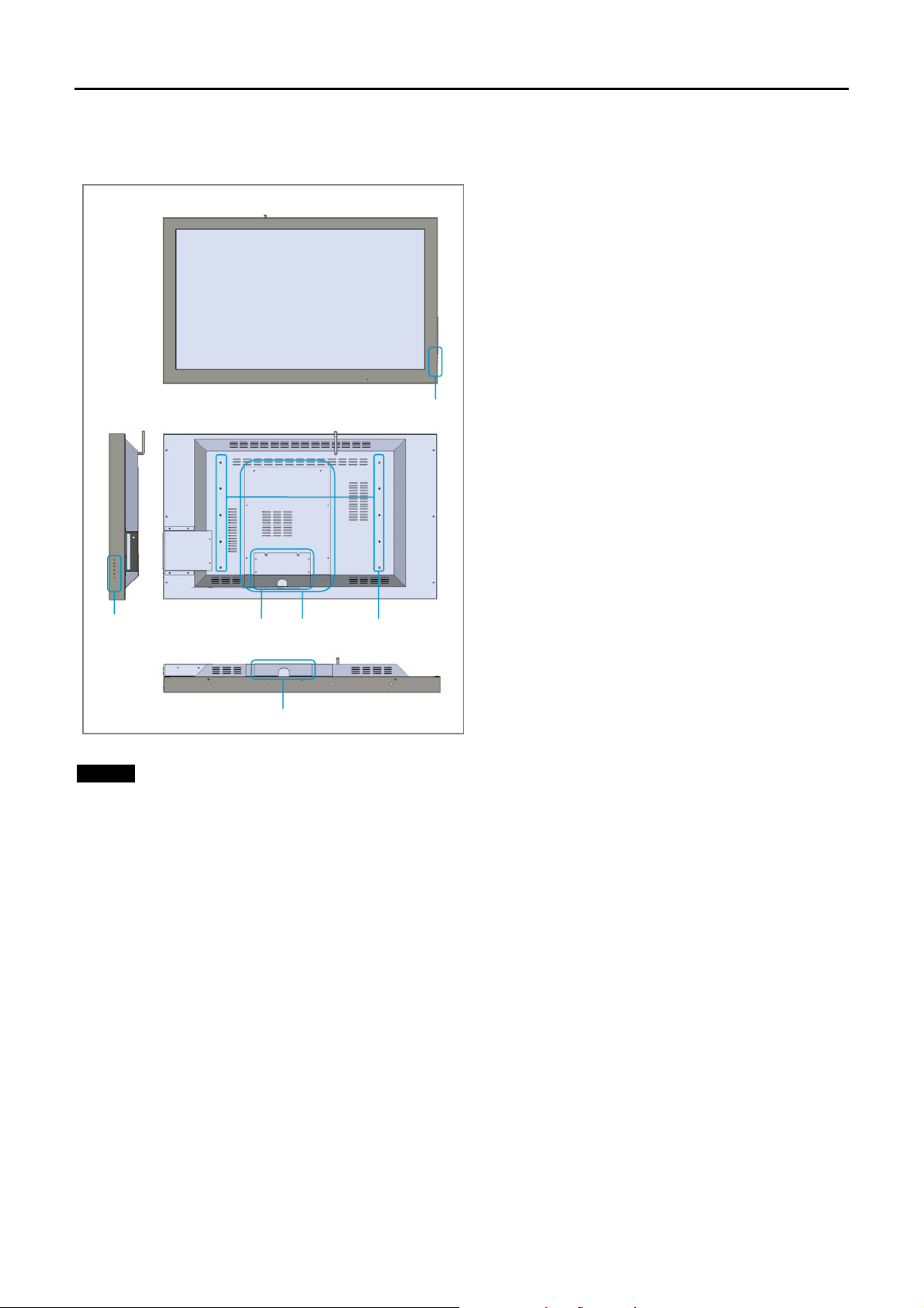
Front / Rear / Side / Bottom Views
Front View
X
Rear View
x
X
Bottom View
NOTE
Be sure to familiarize yourself with all the locations of various controls and connectors before installing the
display unit.
[
[
Y
Z
X Indicator and OSD Control Buttons
The power and standby indicator lights up in green
when the display unit is powered on. The indicator
lights up in red in the standby mode and in orange
when the display enters the power saving mode while
a signal is input from a computer.
See the “OSD (On-Screen-Display) Control Button”
section for more details on page 23.
Y Computer Access Panel
Access to the embedded computer is easily obtained
through the easy access panel located in the rear of
the display unit. The access panel can be easily
removed by unscrewing six large screws by hand.
Z Wall Mount Installation Holes
Use the ten wall mount installation holes to install the
wall mount bracket or optional stand (not supplied).
[ Connector Panel Cover
For details on the connector panel, see “Connector
Panel” on page 13.
Page 8
Page 9
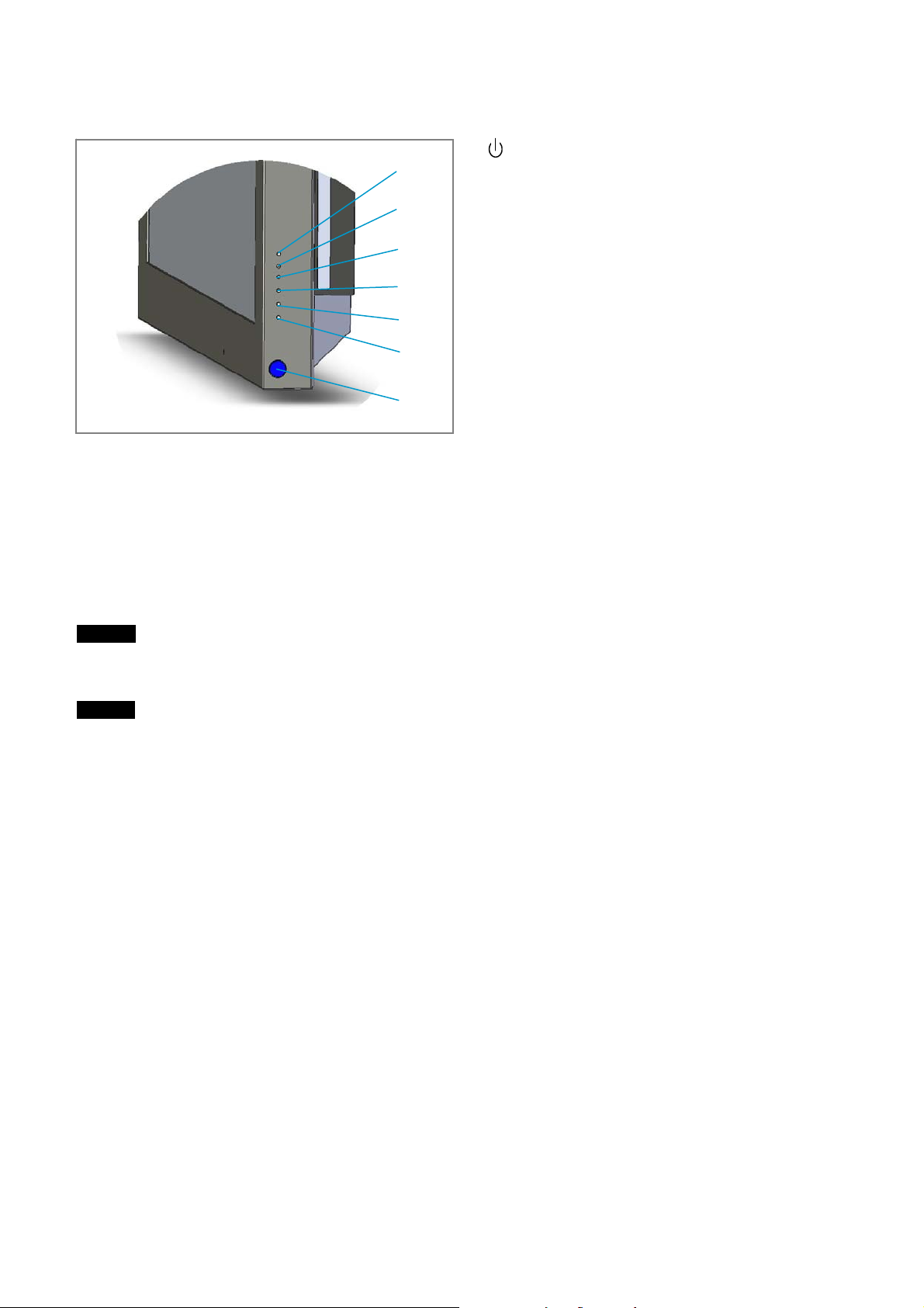
Control Button Section (Side)
X Power Button
^
]
\
[
Z
Y
X
] Power and Standby Indicator Light
The power and standby indicator lights up in green when the display unit is powered on. The indicator lights up
in red in the standby mode and in orange when the display enters the power saving mode while a signal is input
from a computer.
^ Rubber Plug
Not used.
NOTE
To turn off the display and the embedded computer, use the remote control or execute the Windows™
shutdown process from the computer.
NOTE
To protect the LCD panel, a certain amount of time is required to turn the unit on. Wait about 10 seconds after
one operation before executing the next operation.
Press to power on the display unit and the embedded
computer. Press again to return to the standby mode.
Y Menu Button
Press to show menus. Press again to hide them.
Z Select Button
Press to set your choice.
[ \ ©/ª Up/Down Buttons
Press to move the cursor up or down
Page 9
Page 10
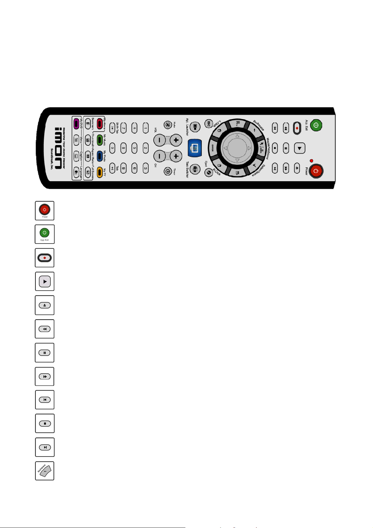
Remote Control (Optional)
iMON Pad remote controller is designed to control the power of both the LCD display and the internal computer
and it will also serve as the mouse pointer using the Pad Controller of the remote controller. Using iMON, iMON
pad remote controller can control not only iMEDIAN, but also every Windows applications. The following is the
normal usage of the buttons on the iMON Pad remote controller. Please see the section ‘Using remote controller
on iMEDIAN’ for instructions on using iMON Pad remote controller on iMEDIAN.
iMON Pad Controller
Power Button: This button is used to turn both the LCD display and computer On and Off.
Application Exit Button: This button generates the keyboard short command, [ALT]+[F4], which is
used for closing the active window.
Record Button: This button is used to generate ‘Record’ command in various media applications.
Play Button: This button is used to generate ‘Play’ command in various media applications.
Open Button: This button is used to generate ‘File/Folder Open’ command in various media
applications.
Rewind Button: This button is used to generate ‘Rewind’ command in various media applications.
Pause Button: This button is used to generate ‘Pause’ command in various media applications.
Fast Forward Button: This button is used to generate ‘Fast Forward’ command in various media
applications.
Previous Button: This button is used to generate ‘Previous’ command in various media
applications.
Stop Button: This button is used to generate ‘Stop’ command in various media applications.
Next Button: This button is used to generate ‘Next’ command in various media applications.
Backspace Button: This button functions identically to the [Backspace] key of the keyboard.
Page 10
Page 11
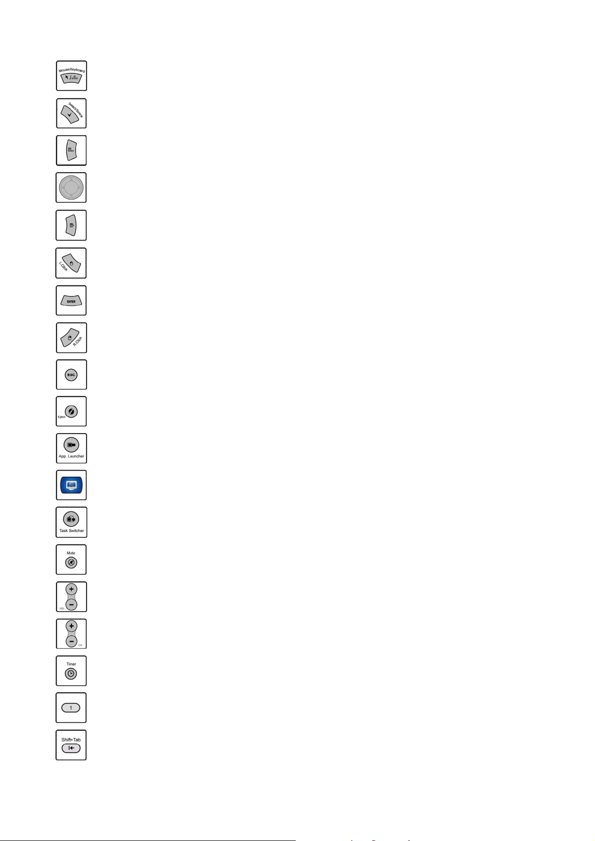
Mouse/Keyboard Button: This button is used to toggle Pad controller operation mode. Pressing
this button will toggle the mode of the Pad controller between mouse mode and keyboard mode.
Select/Space Button: This button functions identically to the [Space] key of the keyboard.
Windows Logo (Start) Button: This button opens the start menu and functions like the [Windows
Start] key of the keyboard.
Pad Controller: This Pad is used to move the mouse pointer in mouse mode, and to input four way
arrow keys in the keyboard mode.
Windows Menu Button: This buttons opens the menu and functions like the [Menu] key of
keyboard.
Left Click Button: This button functions as the [Left Click] button of the mouse.
Enter Button: This button functions as the [Enter] key of the keyboard.
Right Click Button: This button functions as the [Right Click] button of the mouse.
Escape Button: This button functions as the [ESC] key of the keyboard.
Eject Button: This button is used to open the ODD (CD/DVD) drive of the computer system.
Application Launcher Button: This button executes the Application Launcher which can run
numerous pre-assigned windows applications and files.
Quick Launch Button: This button runs the assigned special application directly. The default
assigned application is iMEDIAN. You can change the assigned application in Setup menu of the
iMON Manager.
Task Switcher Button: This button is used for choosing the application among the current running
applications. This feature is similar to the [ALT]+[TAB] keyboard shortcut command.
Mute Button: This button is used to mute/unmute the volume.
Volume Up/Down Button: This button is used to adjust the volume up or down.
Channel Up/Down Button: This button is used to change the channel up or down.
Timer Button: This button runs the iMON timer. The iMON timer feature can turn off the computer
or set the alarm assigned in Setup.
Numeric Button: The numeric buttons from 0 to 9 are custom buttons that can be assigned by
users.
Shift+Tab Button: This button is used identically to [Shift]+[Tab] of the keyboard.
Page 11
Page 12
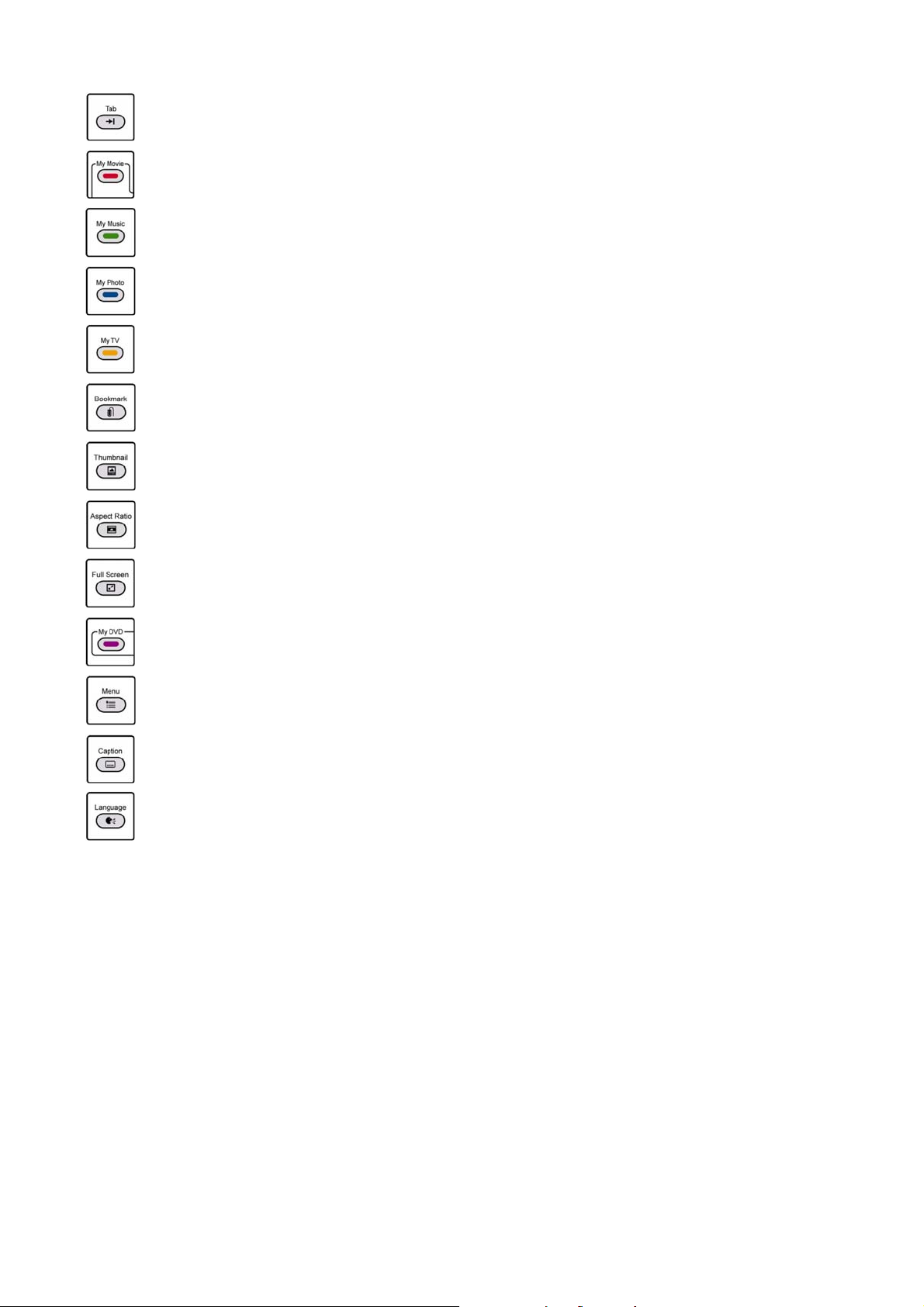
Tab Button: This button functions identically to the [Tab] key of the keyboard.
My Movie Button: This button is used to go to the Movie View directly in iMEDIAN, Media Center
and Power Cinema.
My Music Button: This button is used to go to the Music View directly in iMEDIAN, Media Center
and Power Cinema.
My Photo Button: This button is used to go to the Photo (picture) View directly in iMEDIAN, Media
Center and Power Cinema.
My TV Button: This button is used to TV View directly in iMEDIAN, Media Center and Power
Cinema.
Bookmark Button: This button is used to generate ‘Bookmark’ command in various media
applications.
Thumbnail Button: This button is used to generate ‘Thumbnail’ or ‘Capture Image’ command in
various media applications.
Aspect Ratio Button: This button is used to generate ‘Change the Aspect Ratio’ command in
various media applications.
Full Screen Button: This button is used to generate ‘Full Screen’ command in various media
applications.
My DVD Button: This button is used to go to the DVD view directly in iMEDIAN, Media Center and
Power Cinema.
Menu Button: This button is used to generate ‘DVD Menu’ command in DVD applications.
Caption Button: This button is used to generate ‘Change the Caption/Subtitle’ command in DVD
applications.
Language Button: This button is used to generate ‘Change the Language/Audio’ command in DVD
applications.
Using iMEDIAN
iMEDIAN is designed to you enjoy various media files such as music, movies and photos in local and network
PC, and use multimedia devices like DVD, TV, digital camcorder and web camera using the Pad remote
controller.
Page 12
Page 13
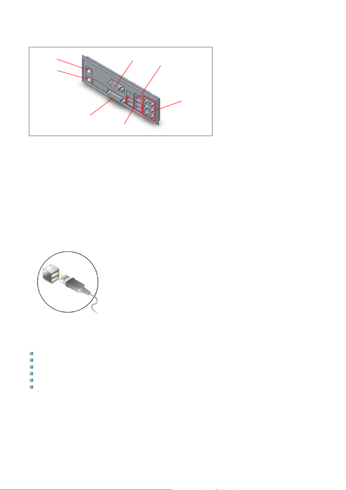
Connector Panel
X
Y
Z
^
]
\
[
X Mouse PS/2 Connector
The standard PS/2 mouse DIN connector is for a PS/2 mouse.
Y Keyboard PS/2 Connector
The standard PS/2 keyboard DIN connector is for a PS/2 keyboard.
Z DVI Port
The DVI (Digital Visual Interface) port allows you to connect a LCD monitor. It provides a high-speed digital
interconnection between the computer and its display device. To connect an LCD monitor, simply plug your
monitor cable into the DVI connector, and make sure that the other end of the cable is properly connected to
your monitor.
[ USB Ports
Four USB 2.0 ports are available for connection to various peripheral devices.
The connector panel is located on the
bottom side of the display unit.
(Please remove the connector panel
cover to access the connector panel)
\ Audio Connection Port
These audio connectors are used for audio devices. You can differentiate the color of the audio jacks for
different audio sound effects.
Line-Out (Green }) – Line Out, is a connector for speakers or headphones.
Line-In (Blue }) – Line In, is used for external CD player, tape player or other audio devices.
Mic (Pink }) – Mic, is a connector for microphones.
RS-Out (Black }) – Rear Surround Out in 4, 5.1 and 7.1 channel modes.
CS-Out (Orange }) – Center/Subwoofer Out in 5.1 and 7.1 channel modes.
SS-Out (Gray }) – Side Surround Out in 7.1 channel mode.
] LAN Port
The standard RJ-45 LAN jack is for connection to the Local Area Network (LAN). You can connect a network
cable to it.
Page 13
Page 14
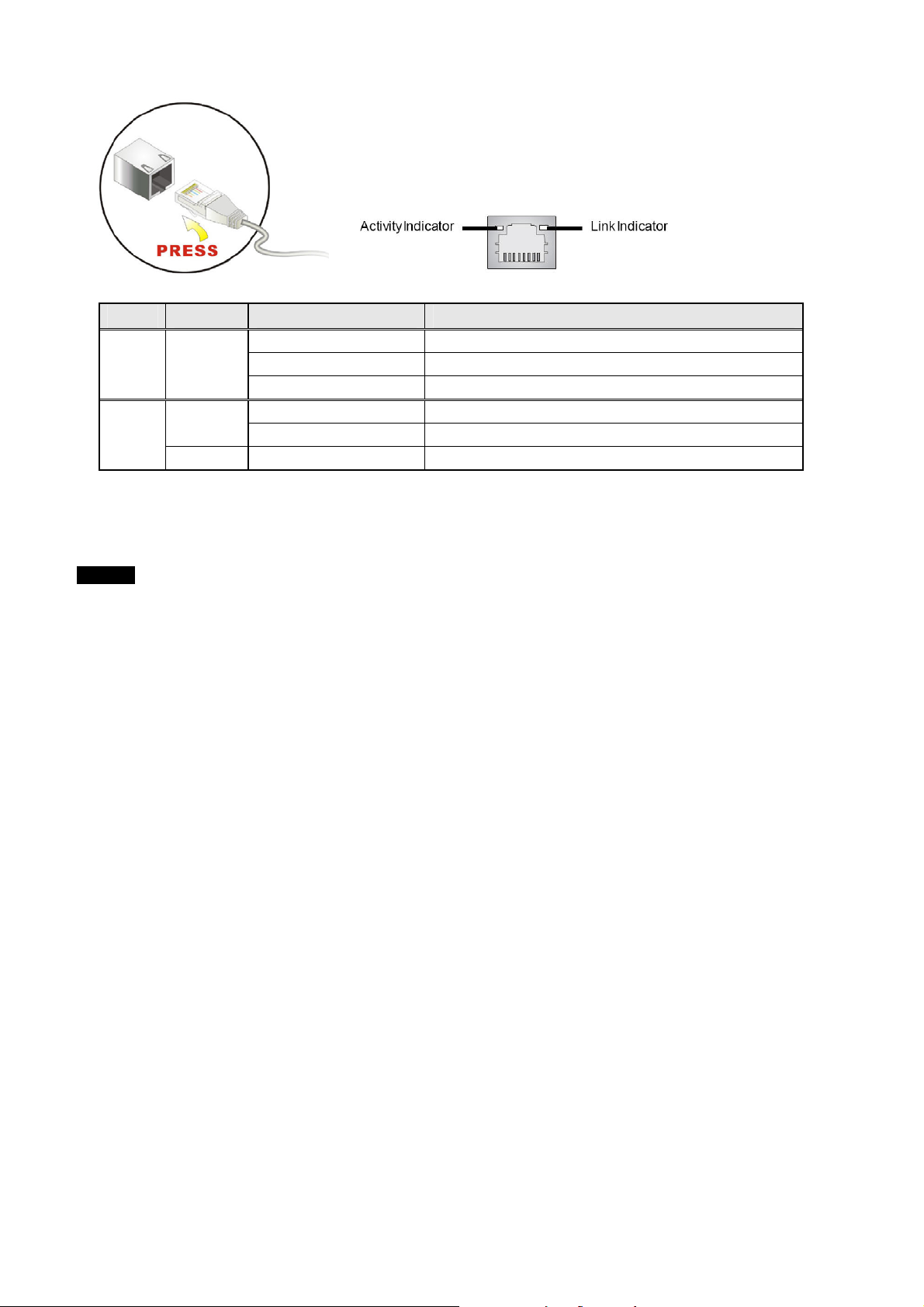
LED Color LED State Status
Off LAN link not established
Left Yellow
Right
Green
Orange On 1000 Mbit/sec data rate selected
On (Steady State) LAN link established
On (Bright & Pulsing) Communicating with another computer over LAN
Off 10 Mbit/sec data rate selected
On 100 Mbit/sec data rate selected
^ VGA Port
The DB 15-pin female connector is provided for connection to a monitor.
NOTE
Normally a DB 15-pin cable is already connected to this connector to provide VGA signal to the screen. Please
do not disconnect this cable unless you want to change the input signal of the screen to a different source.
Page 14
Page 15
IInnssttaallllaattiioonn//MMoouunnttiinngg GGuuiiddee
Before you start
First make sure that the power to each piece of equipment is turned off.
Use connecting cables suitable for the equipment to be connected.
The cable connectors should be fully inserted into the jacks. A loose connection may cause hum and other
noise.
To disconnect the cable, pull it out by grasping the plug. Never pull the cable itself.
Refer to the connection guide of the operation manual of the equipment to be connected.
Insert the plug securely into the AC IN socket.
Installation Precautions
When installing the VM032, VM042(H) or VM047 series systems, please follow the precautions listed below:
Power OFF: When installing the VM032, VM042(H) or VM047 series system(s), make sure the power is off.
Failing to turn off the power may cause severe injury to the body and/or damage to the system.
Qualified Personnel: Only certified or qualified personnel should install and modify onboard functionalities.
Mounting: The VM032, VM042(H) and VM047 series systems are heavy devices. When mounting the
system onto a rack, panel, wall or arm, make sure that at least two people are assisting with the procedure.
Anti-static Discharge: If a user opens the rear panel of the VM032, VM042(H), or VM047 series system to
configure, replace or add peripheral devices, be sure to ground the body first or wear an anti-static
wristband.
Preinstalled Components
The following components are preinstalled in the VM032, VM042(H) and VM047 series systems:
Mainboard
TFT LCD screen
2 x 1GB DDR2 memory module
Wireless LAN module (Optional)
Remote control (Optional)
DVD±RW drive (Optional)
80GB SATA II hard disk drive
NOTE
Installation or replacement of some of the components is described in the following sections.
Installation and Configuration Steps
The following installation steps must be followed:
STEP 1 Unpack the VM032, VM042(H) or VM047 series system from its box.
STEP 2 Mount the VM032, VM042(H) or VM047 series system.
STEP 3 Connect the main power cord and any other peripheral devices to the bottom connector panel of the
VM032, VM042(H) or VM047 series system.
STEP 4 Turn the power ON and configure the system.
Unpacking
To unpack the VM032, VM042(H) or VM047 series system(s), follow the instructions below:
WARNING!
The front side of the LCD screen has a protective plastic cover attached to the screen. Only remove the
protective cover after the monitor has been properly installed. This ensures the screen is protected during the
installation process.
Page 15
Page 16
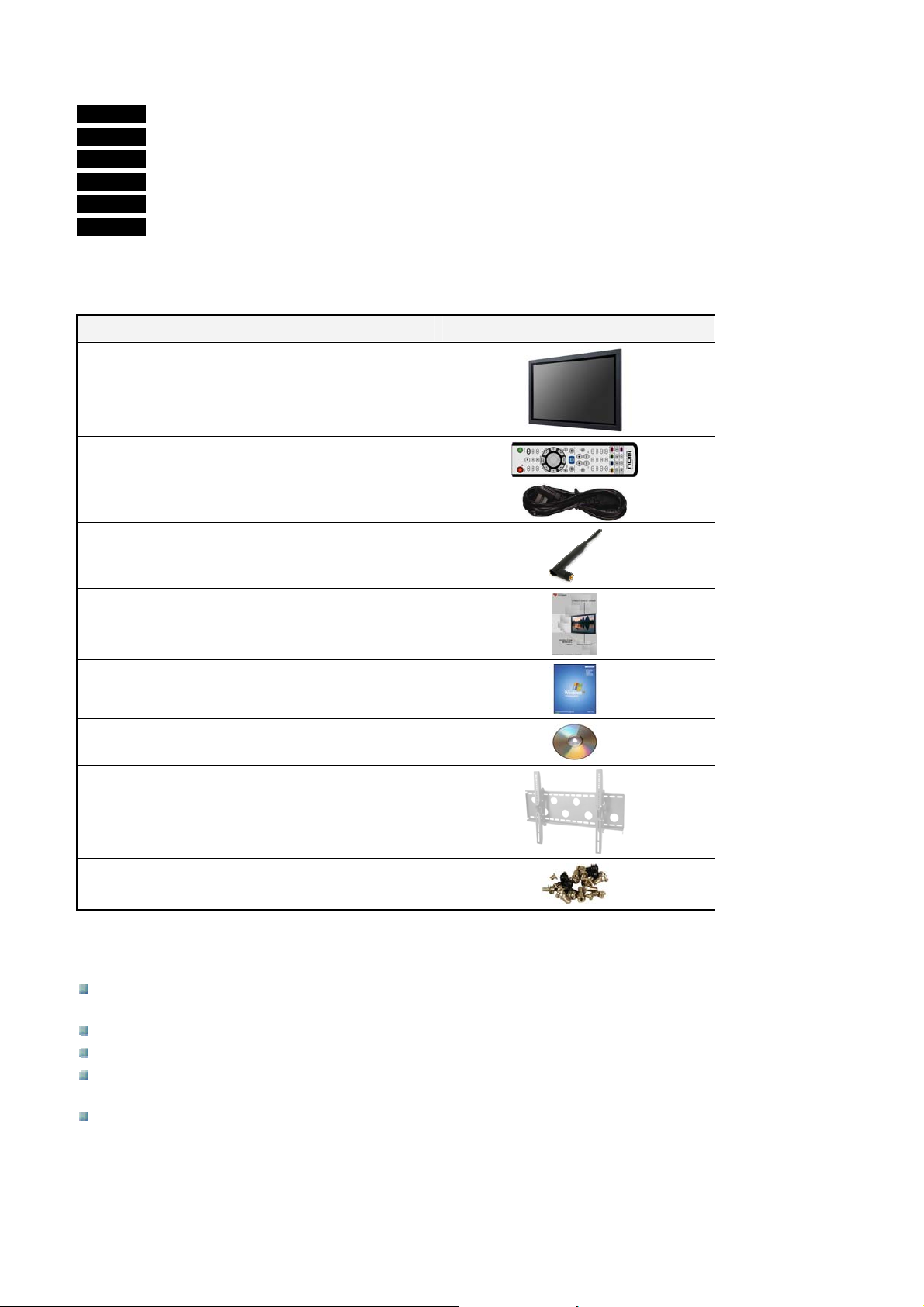
STEP 1 Use a box cutter, a knife, or a sharp pair of scissors to cut the seals on top side of the carbon box.
STEP 2 Open the carbon box.
STEP 3 Lift the unit carefully out of the box.
STEP 4 Remove both polystyrene ends, one from each side.
STEP 5 Pull the safety plastic cover off the monitor screen.
STEP 6 Make sure all the components listed in the packing list are present.
Packing List
The VM series monitor is shipped with the following standard components:
Quantity Description and Part Number Image
VM032, VM042(H) or VM047
1
1
1
Series System
(Part number: )
Remote controller (Optional)
(Part number: )
Power cord
(Part number: )
1
1
1
1
1
1
Wireless LAN antenna (Optional)
(Part number: )
Operation manual
(Part number: )
Windows™ XP Professional CD
(Part number: )
Driver CD
(Part number: )
Wall mount
(Part number: )
Screw set
(Part number: )
Mounting Space Requirements
To prevent internal heat buildup from sealing off the display, make sure to ensure proper ventilation by
leaving open the minimum amount of space around the display as illustrated below.
The ambient temperature must be 0°C to 35°C (32°F to 95°F).
When installing the display horizontally, use the optional display stand (not supplied).
Installation of hardware such as brackets, screws, or bolts is not specified and is up to the authorized local
dealers. Consult with qualified personnel for installation.
While the display is on, a certain amount of heat builds up inside. This can cause burns. Avoid touching the
top or rear of the unit when it is powered on or just after it has entered standby mode.
Page 16
Page 17
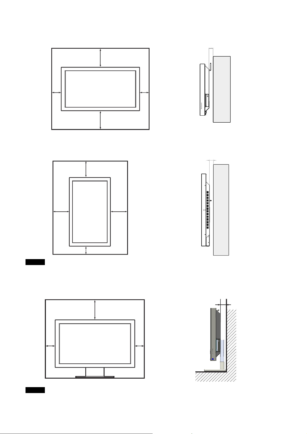
Mounting the Display Horizontally
(
(
)
(
)
Front
9.875”
(250mm)
4”
(100)
9.875”
(250mm)
Mounting the Display Vertically
Front
7.875”
(200mm)
4”
(100)
Side
Side
2”
2”
(50mm)
Units: inches (cm)
50mm)
9.875”
(250mm)
4”(100mm)
9.875”
(250mm)
Units: inches (mm)
NOTE
When mounting the LCD display unit vertically, make sure the POWER switch is at the lower position.
Using the Optional Stand (not supplied)
Front
4”
100
7.875”
(200mm)
4”
100
Side
(100mm)
4”
Units: inches (mm)
NOTE
When moving or installing the LCD display unit, it is recommended that at least two people do so to prevent any
damage and/or injury to both the display unit and people moving or installing the unit.
Page 17
Page 18
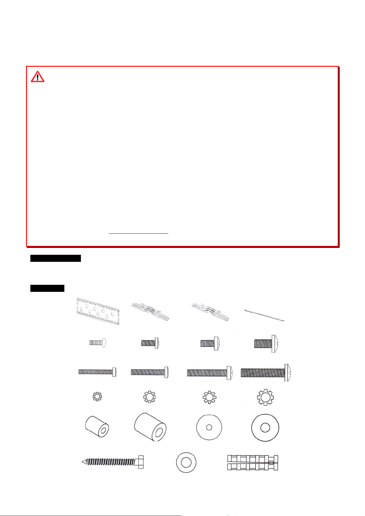
Mounting the System
A
)
(1)
g
)
y
(
x
r
(4)
r
(4)
r
(4)
p
r
(4)
r
(4)
r
(8)
g
r
(6)
Wall Mounting
WARNING!
5 Do not begin to install the system until you have read and understood the instructions and warnings
contained in this section.
5 Make sure that the supporting surface will safely support the combined load of the system and all attached
hardware and components.
5 Never exceed the Maximum Load Capacity of 220 lb (100 kg).
5 If mounting to wood wall studs, make sure that mounting screws are anchored into the center of the studs.
Use of an “edge to edge” stud finder is highly recommended.
5 Always use an assistant or mechanical lifting equipment to safely lift and position the system.
5 When installing wall mounts on cinder block, verify that you have a minimum of 1-3/8” of actual concrete
thickness in the hole to be used for the concrete anchors. Do not drill into mortar joints. Besure to mount in a
solid part of the block, generally 1” (25 mm) minimum from the side of the block. It is suggested that a
standard electric drill on slow setting is used to drill the hole instead of a hammer drill to avoid breaking out
the back of the hole when entering a void or cavity.
5 Concrete must be 2000 psi density minimum. Lighter density concrete may not hold concrete anchor.
5 Concrete anchors are NOT intended for attachment to concrete walls covered with a layer of plaster, drywall,
or other finishing materials. If mounting to concrete wall covered with plaster/drywall is unavoidable,
plaster/drywall (up to 5/8” thick) must be counterbored. Be sure concrete anchors do not pull away from
concrete when tightening screws. If plaster/drywall is thicker than 5/8”, custom fasteners must be used.
5 Tighten the screws firmly, but do not overtighten. Overtightening can damage the items, greatly reducing their
holding power.
Required Tools
Drill, level, 3/16” drill bit, 1/2” masonry bit for brick concrete or concrete block installations, wrench or socket set,
Philips screwdriver
Parts List
A
Wall Plate (1
M4x12 Bolt
30 Bolt (4) M5x30 Bolt(4) M6x35 Bolt(4) M8x40 Bolt (4)
M4
M4 Lock washe
M4/M5 S
BB Left monitor bracket
4) M5x12 Bolt(4) M6x12 Bolt(4) M8x25 Bolt (4)
M5 Lock washe
ace
M6/M8 Space
bolt (6) Lag bolt washe
La
CC Ri
M6 Lock washe
M4/M5 Washe
ht monitor bracket (1
Concrete Anchor (6)
DD Safet
M8 Lock washer (4)
M6/M8 Washer (8)
Page 18
bar (1)
Page 19
NOTE
r
r
r
Not all bolts, lock washers, spacers, and washers are used during the installation.
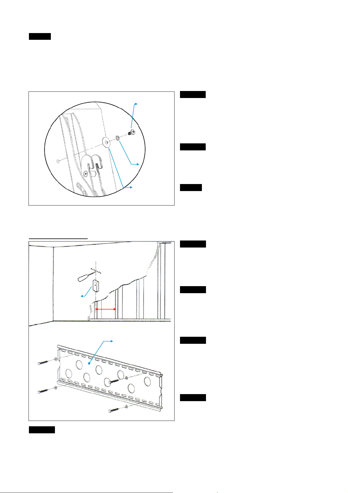
To mount the VM032, VM042(H) or VM047 series system(s) onto the wall, please follow the steps below.
Mounting Monitor Brackets to the System
STEP 1
M6x35 bolt
The VM042(H) system uses M6x35 bolts for the
monitor brackets. Thread the M6x35 bolt through an
M6 lock washer, an M6/M8 washer, the monitor
bracket (BB/CC) and finally into the monitor system
(left).
STEP 2
Repeat the above process for the remaining monitor
M6 lock
washe
bracket.
M6/M8
washe
NOTE
Make sure the monitor brackets are vertically
centered and level with each other.
Mounting the Wall Plate
Wood Stud Mounting
Stud
senso
STEP 5
Attach the wall plate to the wall using 4 pieces of 1/4”x2-1/2” lag bolts and 4 pieces of lag bolt washers. Make
sure the wall plate is oriented so the flat surface in the center of the plate is against the wall and that a set of lag
bolts is on each side of the two large holes in the center as shown above.
STEP 1
Select the location on the wall for wall plate. Make
sure there are sufficient spacing as mentioned in the
previous section between the monitor and walls when
selecting the location.
STEP 2
16
inches
The wall plate (AA) must be mounted to two wood
studs at least 16” (406mm) apart. Use a stud sensor
to locate two adjacent studs. It is a good idea to verify
where the studs are located with an awl or thin nail
shown left.
Wall plate
STEP 3
Pre-drill a 2-1/2” (64mm) deep hole at the desired
height in each stud using a 3/16” drill bit. Make sure
these holes are in the center area of the studs and
level with each other. Use the wall plate as a
template to mark the location of the second hole in
each stud.
STEP 4
Drill 2-1/2” (64mm) deep holes using the 3/16” drill bit
in the marked locations.
Page 19
Page 20
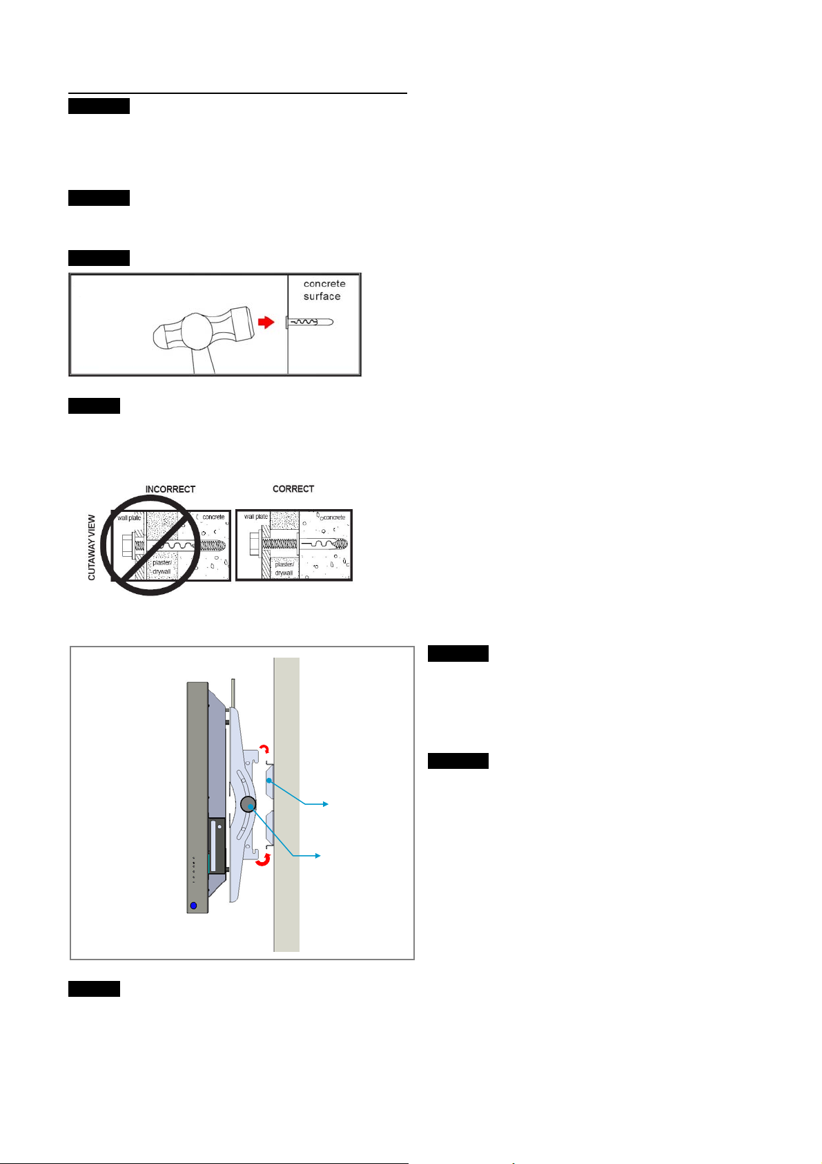
Brick, Solid Concrete and Concrete Block Mounting
STEP 1
Use the wall plate (AA) as a template to mark six hole locations on the wall. The outer holes must fall to the left
and right of the two holes in the middle of the plate; three in the top row of slots and three more in the bottom
row. Make sure the holes are level and there is at least 6” (152mm) distance between any two holes.
STEP 2
Pre-drill the holes with a 1/2” drill bit to at least 2-1/2” (64mm) in depth.
STEP 3
Insert a concrete anchor into each holes that were drilled in
the previous step. Make sure the anchor is seated completely
flush with the concrete surface. Use a hammer if the anchor
does not seat properly.
NOTE
Concrete anchors are not intended for attachment to concrete walls covered with a layer of plaster, drywall, or
other finishing material. If mounting to concrete walls covered with plaster or drywall is unavoidable,
plaster/drywall (up to 5/8” thick) must be counterbored as shown below.
Hanging the Monitor onto the Wall Plate
STEP 1
First hook the monitor brackets over the top of the
wall plate as shown left, then let the bottom of the
monitor brackets swing in under the bottom of the
wall plate.
STEP 2
Once the system has been installed properly on the
Wall plate
Tilt adjustment
knob
NOTE
When loosening the tilt adjustment knobs, the monitor may suddenly tilt downwards and cause injury or damage.
Make sure to hold the monitor firmly when adjusting the tilt of the monitor to prevent injury or damage.
wall plate, the horizontal position of the system can
be adjusted. The black knobs on are used to adjust
the tilt position of the monitor. Loosen both knobs
and adjust the tilt of the monitor until satisfied then
tighten both knobs. The monitor can be tilted up or
down by 15°.
Page 20
Page 21
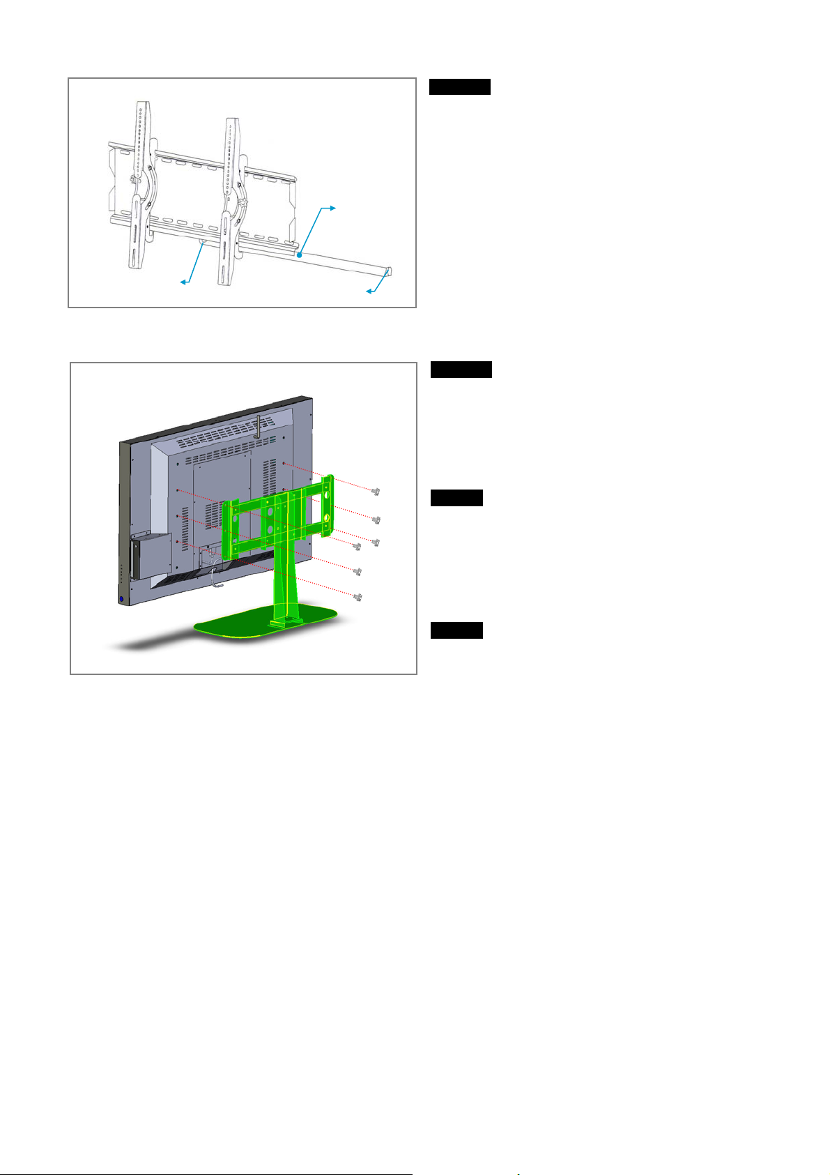
Padlock hole
Bend facing the wall
Using the Monitor Stand (Optional)
Safety bar
STEP 3
Once the system is in place, insert the safety bar into
the slots in the bottom of the monitor brackets so that
it sits behind the bottom tab on the wall plate as
shown left. The bend at the end of the safety bar
should face toward the wall. Once the safety bar
passes out the other side of the wall plate, a padlock
can be added to the hole at the end of the safety bar
for additional security.
STEP 1
Using a Philips screwdriver, tighten six screws as
shown on the left to install the optional monitor stand.
NOTE
To prevent scratching the screen, set a cloth on a flat,
level surface that will support the weight of the
screen. Place screen face side down. Place monitor
stand bracket on back of screen and align to holes.
NOTE
The vertical position of the monitor may be adjusted
by changing the hole positions.
Page 21
Page 22
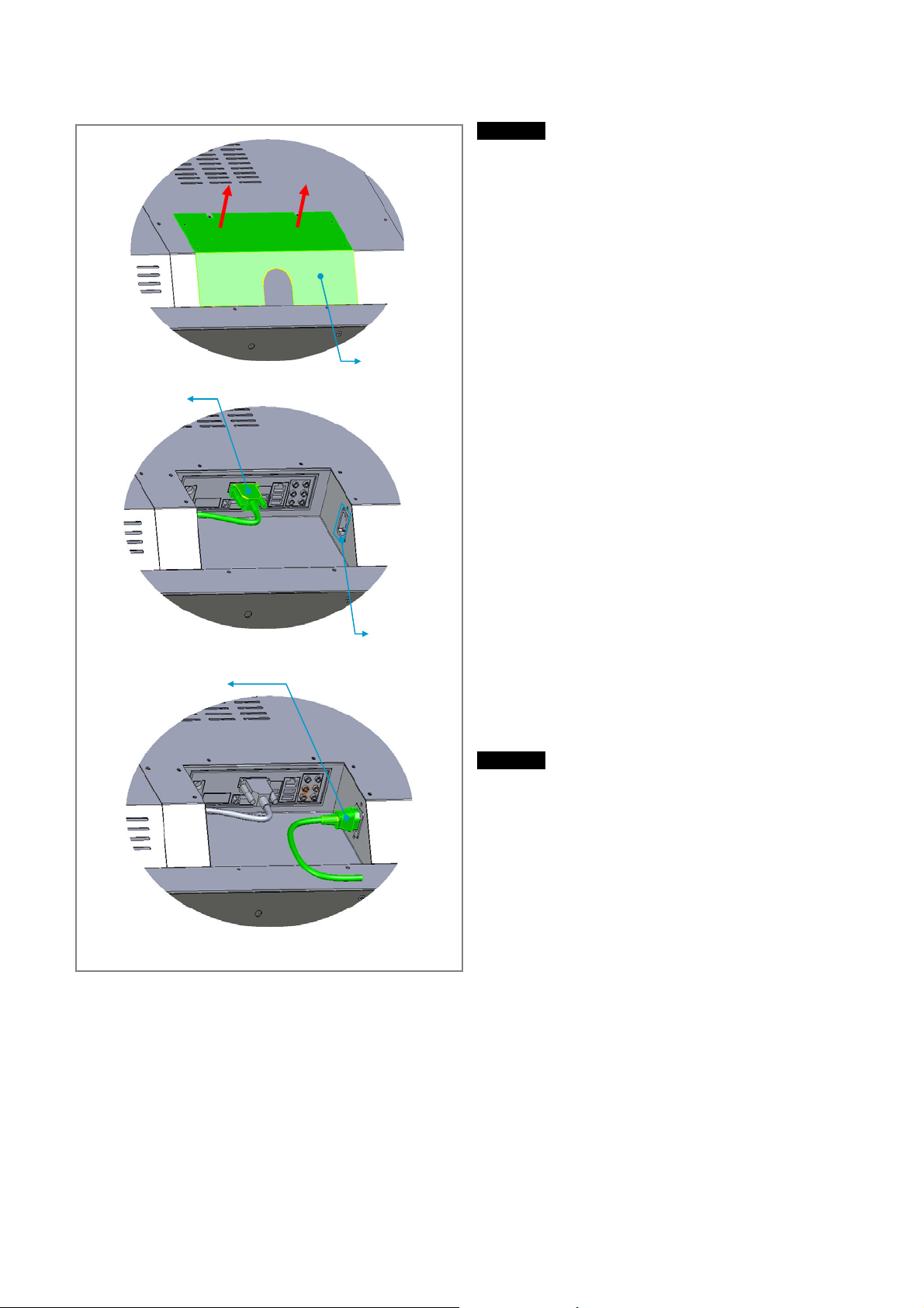
Connecting the AC Power Cord
Connector
panel cover
VGA monitor
cable
AC power
socket
AC power cord
Connecting the Speakers (Optional)
STEP 1
Remove the connector panel cover to reveal the
connector panel.
Removing the connector panel will reveal the
connector panel and the AC power socket. You will
also notice the VGA monitor cable that is already
connected to the VGA port of the connector panel.
STEP 2
Plug the AC power cord into the AC power socket
and install the connector panel cover.
Page 22
Page 23
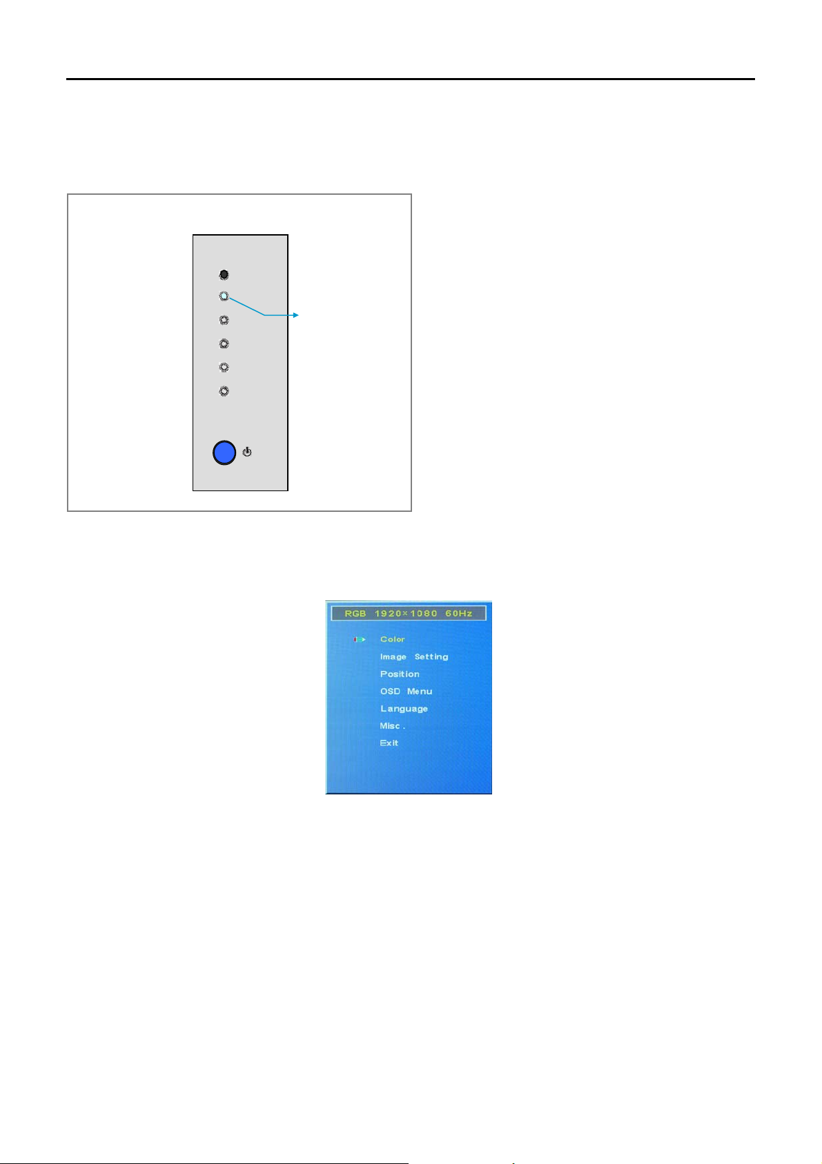
UUssiinngg OOnn--SSccrreeeenn--DDiissppllaayy ((OOSSDD)) MMeennuuss
Operating OSD Menus
Menu operating buttons
Use the buttons on the LCD display unit for On-Screen Display menu operations.
OSD Control Button Panel
S
T
Select
Menu
Configuration of the Menu
1. Press MENU.
Power LED
The main menu appears on the screen.
2. Press ©/ª to move the cursor (blue) to the main menu items you want to select and press SELECT.
The cursor moves to the next menu.
3. Press ©/ª to move the cursor (blue) to the item you want to select and press SELECT.
The menu for the selected item appears and the selected menu turns to pink. Select a different item by
repeating this procedure.
4. Press ©/ª to adjust or select the setting press MENU to set it.
The setting is registered and the menu returns to the previous menu.
To complete the configuration and return to the normal screen, press MENU.
To return to the previous menu level, press ©/ª to move the cursor to the main menu section and press
SELECT.
Page 23
Page 24
Press SELECT from normal screen at any time for automatic screen adjustment. The screen will flicker for a
moment as the screen adjusts automatically to the screen configurations.
To Switch the On-Screen Language
You can select the desired on-screen language for menus and messages from among 5 different languages.
“English” is set as the factory default language.
For details on switching the on-screen language, see “Selecting the On-Screen Language” on page 27.
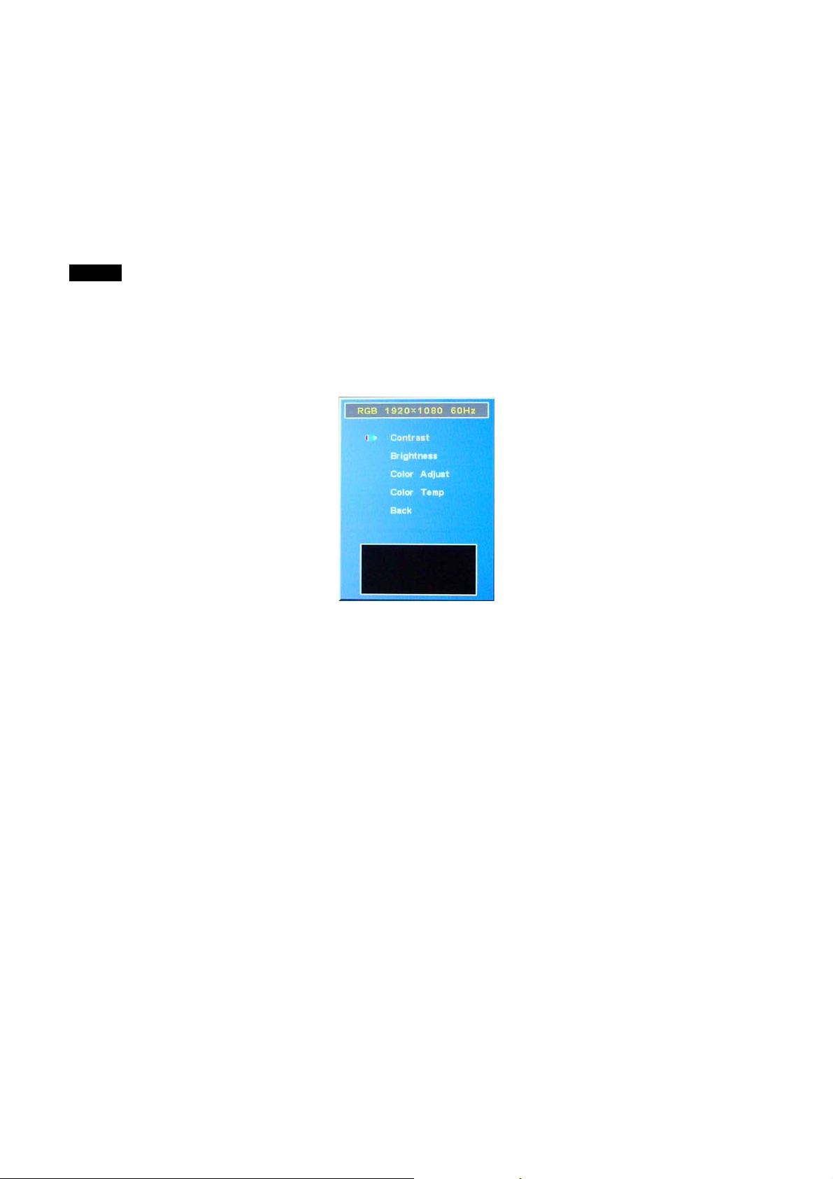
Menu Guide
NOTE
Items that cannot be set or adjusted (depending on the setting or the type of signal input) are shown in dark
gray.
Color Mode
Adjusts the quality of the picture.
Select “Color” with ©/ª and press SELECT.
Contrast
Select “Brightness” with ©/ª and press SELECT. Adjust the contrast with ©/ª within the range of MIN (0) to
MAX (100), then press SELECT.
©: Increases the picture contrast.
ª: Decreases the picture contrast.
Brightness
Select “Contrast” with ©/ª and press SELECT. Adjust the brightness with ©/ª within the range of MIN (0) to
MAX (100), then press SELECT.
©: Makes the picture brighter.
ª: Makes the picture darker.
Color Adjust
Select “Clock” with ©/ª and press SELECT. Adjust the color for RGB with ©/ª within the range of MIN (0) to
MAX (255) for R, B, and B, then press SELECT.
Color Temperature
Select “Phase” with ©/ª and press SELECT. Adjust the color temperature by selecting 9300, 6500, 5800, or
User with ©/ª (If User is selected adjust the set values of each gain with ©/ª).
1. Select the color temperature with ©/ª and press SELECT.
5800: Sets the color temperature to low.
6500: Sets the color temperature to neutral.
9300: Sets the color temperature to high.
Red, Green, and Blue: Sets values for each gain separately.
Page 24
Page 25
2. When you select Red, Green, or Blue, press ©/ª to move the cursor (blue) to the gain that you want to
adjust and press SELECT.
3. Adjust the gain (0 to 100) with ©/ª and press MENU.
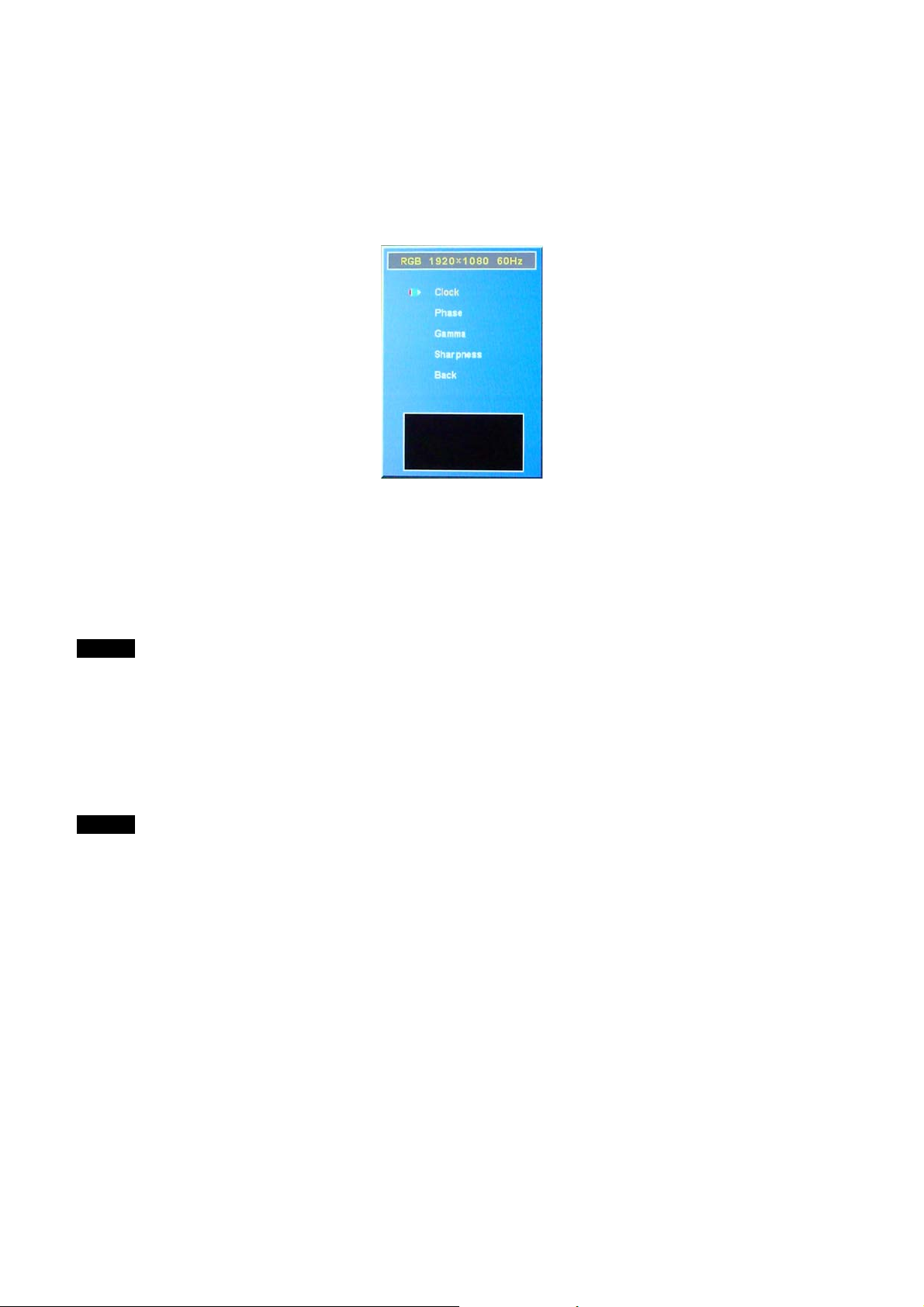
Image Setting
Adjusts the quality of the picture.
Select “Image Setting” with ©/ª and press SELECT.
Clock
Select “Clock” with ©/ª and press SELECT. Adjust the clock frequency with ©/ª within the range of MIN (0) to
MAX (100), then press SELECT.
©: Increases the clock frequency.
ª: Decreases the clock frequency.
NOTE
The clock mode is only enabled during the PC mode.
Phase
Select “Phase” with ©/ª and press SELECT. Adjust the phase with ©/ª within the range of MIN (0) to MAX
(63), then press SELECT.
©: Moves the display position upward.
ª: Moves the display position downward.
NOTE
The phase mode is only enabled during the PC mode.
Gamma
Select “Gamma” with ©/ª and press SELECT. Adjust the Gamma level with ©/ª within the range of MIN (0) to
MAX (3), then press SELECT.
Sharpness
Select “Sharpness” with ©/ª and press SELECT. Adjust the sharpness with ©/ª within the range of MIN (0) to
MAX (4), then press SELECT.
©: Increases the sharpness of the image.
ª: Decreases the sharpness of the image.
Page 25
Page 26
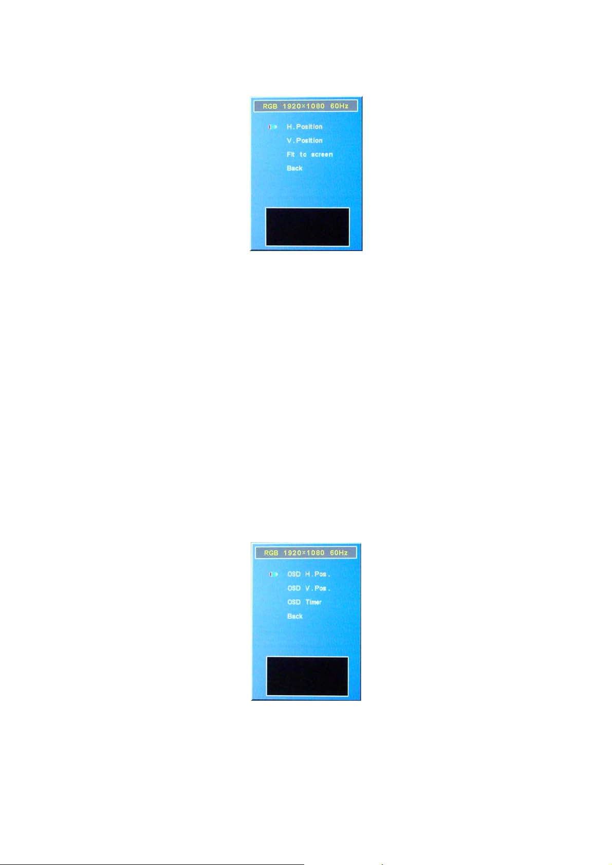
Position
Adjusts the position of the display screen.
Select “Position” with ©/ª and press SELECT.
H. Position
Select “H. (Horizontal) Position” with ©/ª and press SELECT. Adjust the position of the display horizontally with
©/ª within the range of MIN (0) to MAX (100), then press SELECT.
©: Moves the display position right.
ª: Moves the display position left.
V. Position
Select “V. (Vertical) Position” with ©/ª and press SELECT. Adjust the position of the display vertically with ©/ª
within the range of MIN (0) to MAX (100), then press SELECT.
©: Moves the display position upward.
ª: Moves the display position downward.
Fit to Screen
Select “Fit to Screen” with ©/ª and press SELECT. Select from 16:9 or 4:3 aspect ratio with ©/ª the press
SELECT.
OSD Menu
From this menu, various on-screen display related options can be controlled and setup.
Select “OSD Setup” with ©/ª and press SELECT.
OSD H. Position
Select “OSD H. (Horizontal) Position” with ©/ª and press SELECT. Adjust the position of the OSD display
horizontally with ©/ª within the range of MIN (0) to MAX (100), then press SELECT.
©: Moves the OSD display position right.
ª: Moves the OSD display position left.
OSD V. Position
Page 26
Page 27
Select “OSD V. (Vertical) Position” with ©/ª and press SELECT. Adjust the position of the OSD display
vertically with ©/ª within the range of MIN (0) to MAX (100), then press SELECT.
©: Moves the OSD display position upward.
ª: Moves the OSD display position downward.
OSD Timer
Select “OSD Timer” with ©/ª and press SELECT. Adjust the OSD display time with ©/ª within the range of
MIN (0) to MAX (60), then press SELECT. The on-screen display will automatically disappear after the
designated set time in this menu.
©: Increases the OSD display time.
ª: Reduces the OSD display time.
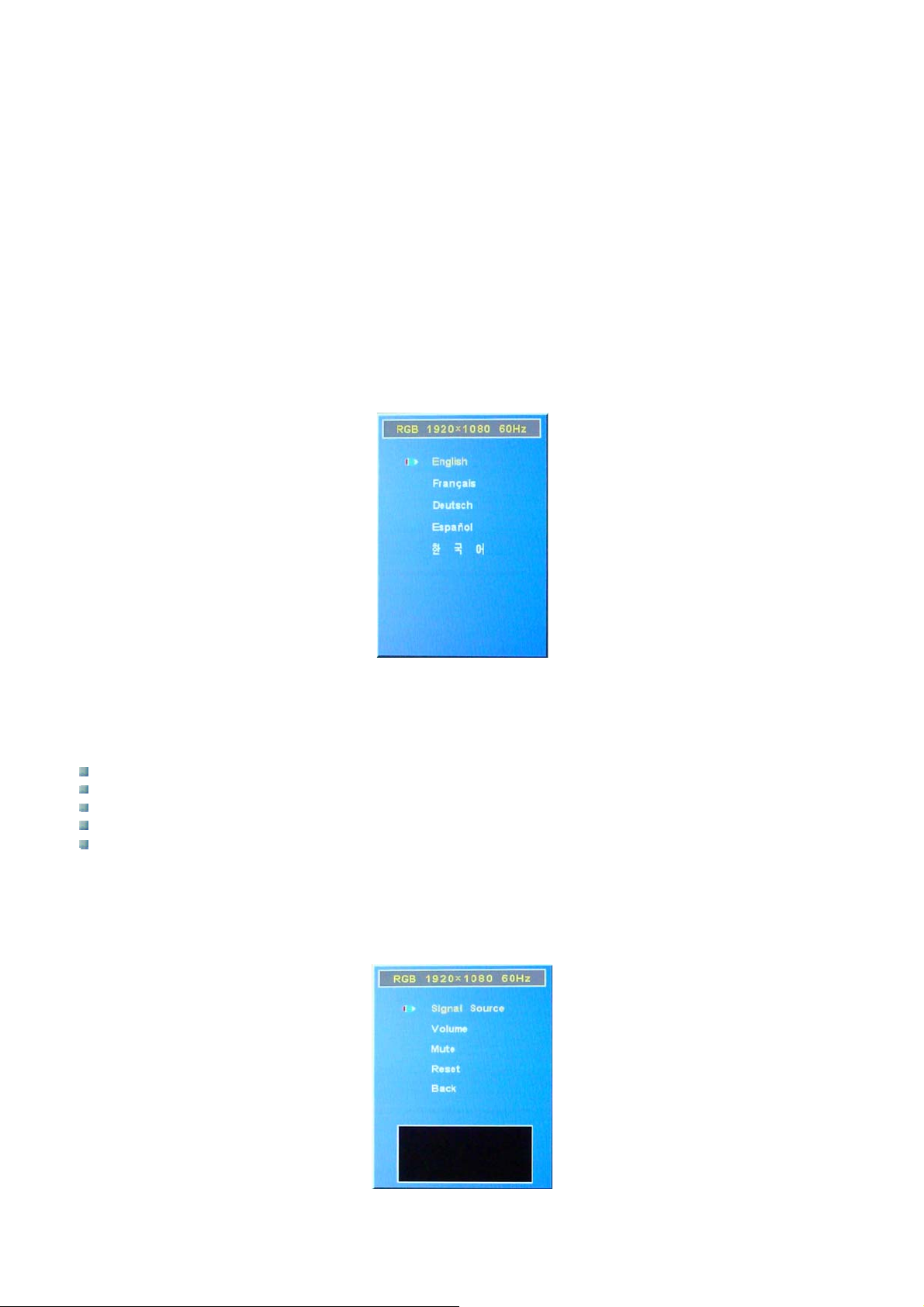
Language
You can select the on-screen language from English, German, French, Spanish and Korean. At the factory, the
default language has been setup in English.
Select “Language” with ©/ª and press SELECT.
Select “Language” with ©/ª and press SELECT. Press ©/ª to the desired language and press SELECT. The
on-screen language is switched to the one you have selected.
English: English
Français: French
Deutsch: German
Espaňol: Spanish
한국어: Korean
Miscellaneous
You can select the desired input signal of the display, control volume (Not available in this system) and reset the
OSD values to factory default.
Select “Misc” with ©/ª and press SELECT.
Page 27
Page 28

Signal Source
Select “Signal Source” with ©/ª and press SELECT. Using ©/ª select DVI or RGB then press SELECT.
Volume
Select “Volume” with ©/ª and press SELECT. Adjust the volume with ©/ª within the range of MIN (0) to MAX
(100), then press SELECT.
©: Increases sound volume.
ª: Decreases sound volume.
NOTE
The volume adjustment is not available in PC mode.
Mute
Select “Mute” with ©/ª and press SELECT. Using ©/ª select ON or OFF then press SELECT.
ON: Mute function is enabled and all sounds are muted.
OFF: Mute function is disabled.
NOTE
The mute feature is not available in PC mode.
Reset
Select “Reset” with ©/ª and press SELECT. Selecting reset will restore all settings to their factory presettings.
Page 28
Page 29
SSppeecciiffiiccaattiioonnss
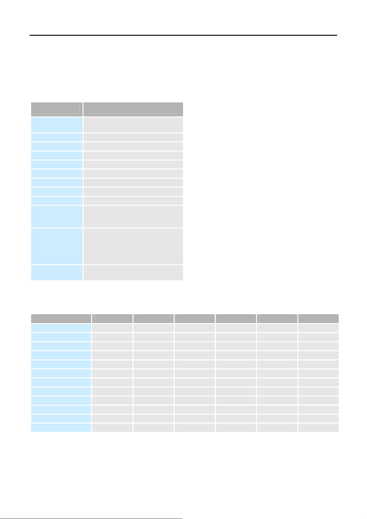
System Specifications
The technical specifications for the VM032, VM042(H) and VM047 series systems are listed in table below.
Mainboard Specifications
Category Specifications
CPU Type
CPU Socket LGA775
System Chipset NVIDIA® GeForce 73PV
Memory Type DDR2 533/667/800 MHz
Memory Slot 2 x DIMM
Standard Memory 2 GB (2 x 1 GB)
Maximum Memory 4 GB (2 x 2 GB)
Ethernet LAN Chip Realtek® RTL 8211BL
Audio Chip Realtek® ALC888
Rear Connectors
Onboard Slots &
Internal Connectors
Operating System
Intel® Core™ Solo/Duo or Core™ 2 Duo,
Core™ 2 Quad, Pentium™ D, Celeron™
1 x DVI, 1 x RJ45 LAN,
1 x Azalia Audio Rack,
4 x USB 2.0, 2 x PS/2,
2 x DDR2 DIMM, 4 x SATA II,
1 x PCIe *1, 1 x CD audio in,
2 x Front panel, 6 x USB 2.0,
2 x Cooling fans,
1 x Front audio,
Windows™ XP Pro (Standard)
Windows™ Vista™ Premium (Optional)
Flat Panel Screen Specifications
The VM032, VM042(H) and VM047 series systems
come with a MSI P6NGM mainboard. The technical
specifications of the mainboard are listed in table
below.
Model VM015 VM019 VM032 VM042 VM042H VM047
Screen Size (Diagonal)
Resolution
Active Area (mm)
Pixel Pitch (mm)
LCD Colors
Viewing Angle
Brightness (cd/m2)
Contrast Ratio
Response Time
Power Consumption
Input Voltage
Electrical Interface
15” (381mm) 19” (482.6mm) 32” (812.8mm) 42” (1066.8mm) 42” (1066.8mm) 47” (1193.8mm)
1024 x 768 1280 x 1024 1366 x 768 1366 x 768 1920 x 1080 1920 x 1080
304.128 x 228.096 376.320 x 301.056 697.6845 x 392.256 930.25 x 523.01 930.24 x 523.26 1039.68 x 584.82
0.297 x 0.297 0.098 x 0.294 0.51075 x 0.17025 0.227 x 0.681 0.4845 x 0.4845 0.5415 x 0.5415
16.2 Million 16.2 Million 16.7 Million 16.7 Million 16.7 Million 16.7 Million
130 / 110 160 / 160 178 / 178 178 / 178 178 / 178 178 / 178
400 300 500 500 500 500
500:1 800:1 1000:1 1000:1 1000:1 1000:1
25 msec 10 msec 10 msec 8 msec 8 msec 8 msec
14.6 W 24.0 W 113.7 W 167.4 W 168.8 W 247.2 W
3.3 V 5.0 V 24.0 V 24.0 V 24.0 V 24.0 V
1ch LVDS 2ch LVDS 1ch LVDS 1ch LVDS 2ch LVDS 2ch LVDS
Page 29
Page 30
MMaaiinnbbooaarrdd
Introduction
The VM032, VM042(H) and VM047 series systems contain the MSI P6NGM mainboard. The mainboard is the
heart of any computer and is responsible for transmitting, receiving and processing data as well as driving the
different onboard devices and peripherals.
CPU
The MSI P6NGM mainboard comes with a preinstalled Intel® Pentium™ D, Core™ Duo, Core™ 2 Duo, Core™
2 Quad, P4EE™, or Pentium™ XE processors. The Intel
on Intel’s next generation 65 nanometer technology with copper interconnect. The Intel
refers to a single core processor and the Intel
®
Core™ 2 Duo processor refers to a dual core processor. The
®
Core™ Duo and Core™ 2 Duo processors are built
®
Core Solo processors
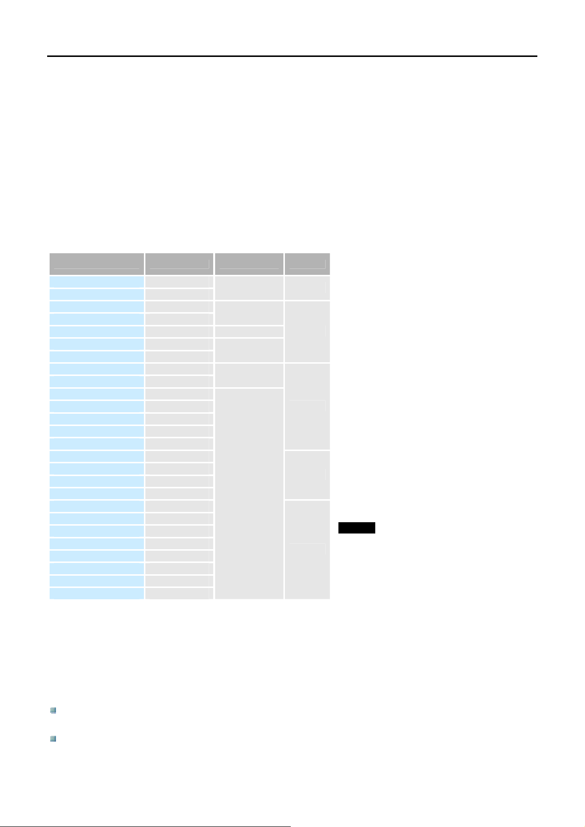
table below shows list of processors that can be installed on MSI P6NGM mainboards.
Processor Number Clock Speed Front Side Bus Cache
Core 2 Quad Q6700 2.66 GHz
Core 2 Quad Q6600 2.40 GHz
Core 2 Duo E6850 3.00 GHz
Core 2 Duo E6750 2.66 GHz
Core 2 Duo E6700 2.66 GHz 1066 MHz
Core 2 Duo E6550 2.33 GHz
Core 2 Duo E6540 2.33 GHz
Core 2 Duo E6400 2.13 GHz
Core 2 Duo E6300 1.86 GHz
Core 2 Duo E4700 2.60 GHz
Core 2 Duo E4600 2.40 GHz
Core 2 Duo E4500 2.20 GHz
Core 2 Duo E4400 2.00 GHz
Core 2 Duo E4300 1.80 GHz
Core Duo E2220 2.40 GHz
Core Duo E2180 2.00 GHz
Core Duo E2160 1.80 GHz
Core Duo E2140 1.60 GHz
Pentium D960 3.60 GHz
Pentium D950 3.40 GHz
Pentium D945 3.40 GHz
Pentium D940 3.20 GHz
Pentium D935 3.20 GHz
Pentium D930 3.00 GHz
Pentium D925 3.00 GHz
Pentium D915 2.80 GHz
1066 MHz 8MB L2
1333 MHz
1333 MHz
1066 MHz
800 MHz
4MB L2
2MB L2
1MB L2
4MB L2
NOTE
With CPU speed changing rapidly, there
might be faster CPUs on the market by the
time you receive this operation manual. The
applicable processor table is for your
reference only.
On-Board Chipset
The MSI P6NGM mainboard has a preinstalled NVIDIA® GeForce 73PV(7100/NF630i) chipset. The NVIDIA®
GeForce 73PV(7100/NF630i) chipset supports Intel’s x86 Core™ 2 Quad processors as well as Core™ 2 Duo,
Pentium™ and Celeron™ processors. With a 1333 MHz system bus, DDR memory technology and support for
Microsoft
®
Windows Vista™ Premium, the NVIDIA® GeForce 73PV(7100/NF630i) chipset enables a scalability
and performance for everyday computing.
NVIDIA® GeForce 7 Series Graphics Processing Unit (GPU) – Industry-leading NVIDIA® GPU delivers
better graphics, faster performance, and a great Microsoft
®
Windows Vista™ experience.
Microsoft® Windows Vista™ Premium Capable – NVIDIA® GPU mainboards are ready for Microsoft®
Windows Vista™ Premium experience when coupled with 1GB of system memory.
Page 30
Page 31

Microsoft DirectX 9.0 Shader Model 3.0 Support – Top-notch compatibility and performance for all Microsoft
DirectX
®
9.0 applications, including Shader Model 3.0 support.
Integrated HDMI™ with On-Chip HDCP – On board HDMI™ connector designed to meet the output
protection management (HDCP) and security specifications of the Blu-ray Disc and HD DVD formats,
allowing the playback of encrypted movie content on PCs when connected to HDCP-capable displays.
Integrated DVI with HDCP – Abel to drive flat-panel displays supporting single-link TMDS at 162MHz pixel
clock. Designed to meet the output protection management (HDCP) and security specifications of the Bluray Disc and HD DVD formats, allowing the playback of encrypted movie content on PCs when connected
to HDCP-capable displays.
PCI Express – Supports PCI Express bus architecture with full bandwidth x16 expansion slot.
NVIDIA® nForce® Storage – Safeguards your most important digital media assets; always reliable, scalable,
and accessible. Includes NVIDIA RAID and drive support.
NVIDIA® RAID and MediaShield™ Technology – Provides a simple point and click wizard-based interface
for creating and managing multi-disk storage configurations. Allows multi-disk designs to be set up for
maximum performance (RAID 0), for data protection (RAID 1), or for a combination of both performance
and protection (RAID 0+1 and RAID 5). Also allows RAID volumes to be converted from one configuration
to another with a single operation. Uniquely allows users to assign an extra disk to any RAID volumes so
that should a disk failure occur, NVIDIA
®
RAID will automatically remove the failed disk and replace it with
the spare.
SATA 3Gb/s – Take advantage of the latest SATA 3Gb/s hard disk drives, which double bus bandwidth and
provides blazingly high disk performance. This technology provides easy-to-install, high-performance but
low-powered hard drives.
NVIDIA® nForce® Networking – NVIDIA® nForce® Networking solution enables Internet connectivity through
industry standard 10/100/1000 Mb/s Ethernet connection.
NVIDIA® Native Gigabit Ethernet – The industry’s fastest Gigabit Ethernet performance eliminates network
bottlenecks and improves overall system efficiency and performance.
NVIDIA® CineFX™ 3.0 Engine – Powers the next generation of cinematic realism. Full support for
Microsoft
®
DirectX® 9.0 Shader Model 3.0 enables stunning and complex special effects. Next-generation
shader architecture delivers faster and smoother game play.
NVIDIA® nView™ Multi-Display Technology – Advanced technology provides the ultimate in viewing
flexibility and control for multiple monitors.
NVIDIA® Digital Vibrance Control™ 3.0 Technology – Allows the user to adjust color controls digitally to
compensate for the lighting conditions of their workspace, in order to achieve accurate, bright colors in all
conditions.
OpenFL® 1.5 Optimizations and Support – Top-notch compatibility and performance for all OpenGL®
applications.
300 MHz RAMDAC – Blazing-fast RAMDAC supports the display with high, ergonomic refresh rates up to
and including 1920x1440 @ 75MHz.
DDR2 Memory Architecture – A state-of-the-art DDR2 memory controller allows high bandwidth and low
latency data access to the CPU. Enables data and information to be relayed through the system as quickly
as possible for incredible performance. Supports up to 4 GB of system memory.
High Definition Audio (HDA) – High definition audio brings consumer electronics quality sound to the PC
delivering high quality sound from multiple channels. Using HAD, systems can deliver 192 kHz/32-bit
quality for eight channels, supporting new audio formats.
USB Ports – A standard plug-and-play interface that provides easy-to-use connectivity for USB devices.
Supports up to 10 USB 1.1/2.0 ports.
Peripheral Device Interfaces, Connectors and Slots
The peripheral device connectors, interfaces and slots on the MSI P6NGM mainboard are listed in the sections
below.
Internal Slots
The slots listed below can all be found on the MSI P6NGM mainboard.
Page 31
Page 32
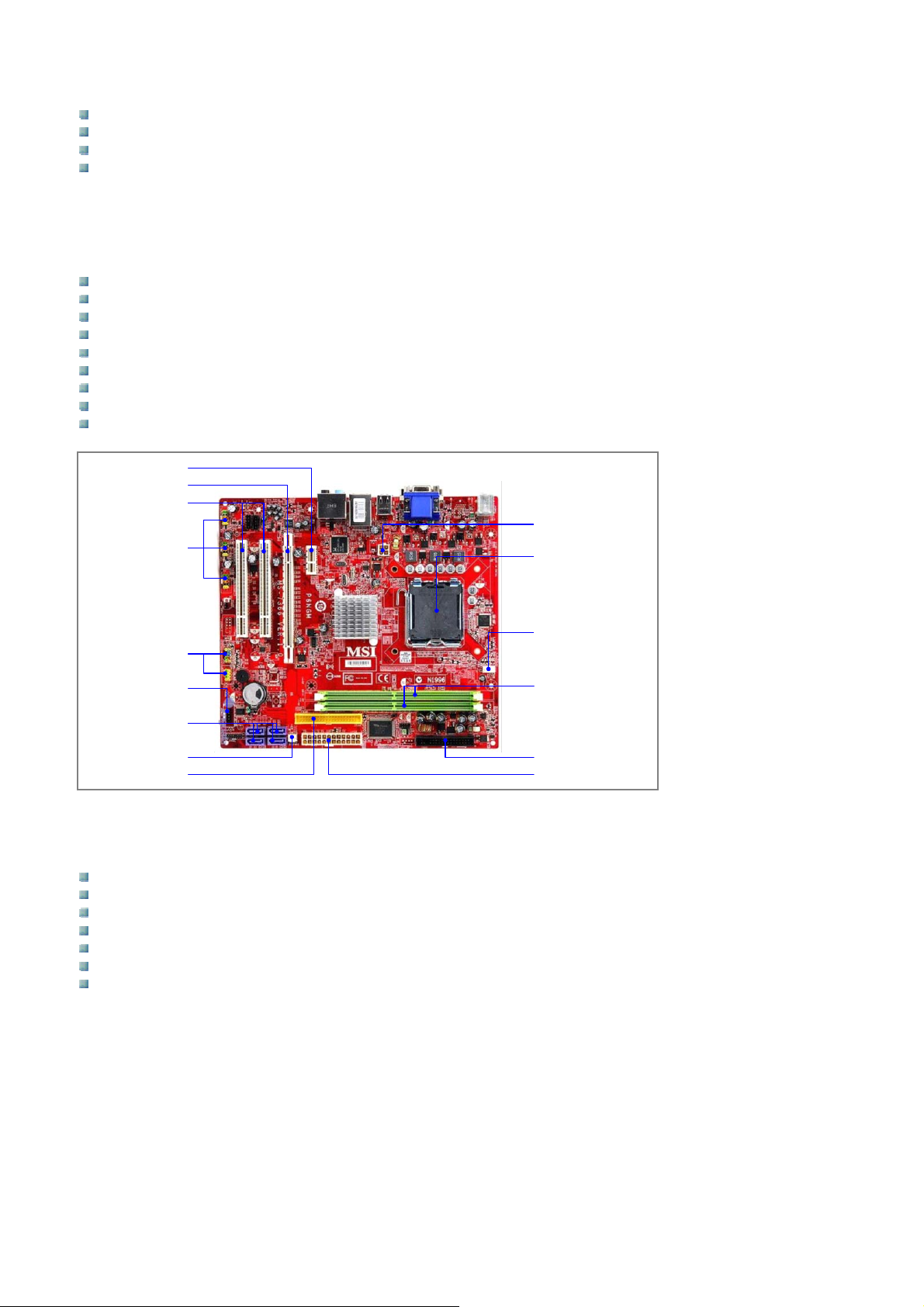
2 x 240-pin DDR2 DIMM slots
1 x PCI (Peripheral Component Interconnect) express x1 slot
1 x PCI (Peripheral Component Interconnect) express x16 slot
2 x PCI (Peripheral Component Interconnect) slots
Internal Peripheral Device Connectors
The peripheral device connectors listed below are located on the MSI P6NGM mainboard and used for the VM
series.
1 x SPDIF(Sony & Philips Digital Interconnect Format)-out pinheader
1 x Serial port pinheader
1 x Floppy disk drive connector
4 x Serial ATA II connectors
1 x IDE connector
6 x USB 2.0 connectors
1 x Front audio connector
1 x CD audio in connector
2 x Front panel connector (Power and reset switch connectors)
PCI Express x1 Slot
PCI Express x16 Slot
PCI Slots
CPU Power
USB 2.0 Connectors
CPU
CPU Fan
Front Panel Connectors
Serial Port Connector
SATA Connectors
System Fan Power
IDE Connector
Memory Slots
FDD Connector
Power Connection (24 pins)
External Peripheral Device Connectors
The peripheral device connectors listed below are located on the MSI P6NGM mainboard.
1 x PS/2 keyboard
1 x PS/2 mouse
4 x USB 2.0 ports
1 x 2 in 1 audio jack
1 x RJ45 LAN port
1 x DVI connector
1 x VGA port
Page 32
Page 33
SSyysstteemm MMaaiinntteennaannccee
System Maintenance Introduction
If the components such as memory or hard disk drive of VM032, VM042(H) and VM047 series systems fail, they
must be replaced by qualified personnel. Please contact the local dealer or vendor to purchase or replace the
parts. Procedures for the rear cover removal and jumper settings for the VM032, VM042(H) and VM047 series
systems are described in sections below.
Mainboard Replacement
Although the mainboard will not fail under normal usage, if it does fail, the mainboard needs to be replaced by
qualified personnel or be returned to the local dealer or vendor for replacement. Please contact the local dealer
or vendor for the replacement of the mainboard.
NOTE
Any attempt to remove and replace the mainboard voids warranty, and the local dealer, vendor, and
manufacturer are not responsible for any consequential damages and injuries.
Mainboard Access Panel Removal
WARNING!
BEFORE REMOVING THE REAR COVER, MAKE SURE THE POWER CORD HAS BEEN DISCONNECTED
FROM THE SYSTEM. Failing to do so may lead to severe damages of the VM series monitors and injury to the
body.
WARNING!
PLEASE TAKE ANTISTATIC PRECAUTIONS WHEN WORKING WITH THE INTERNAL COMPONENTS. The
interior of VM series monitors contain very sensitive electronic components. These components are prone to
electrostatic discharge (ESD). Before working with the internal components, make sure all antistatic precautions
have been observed.
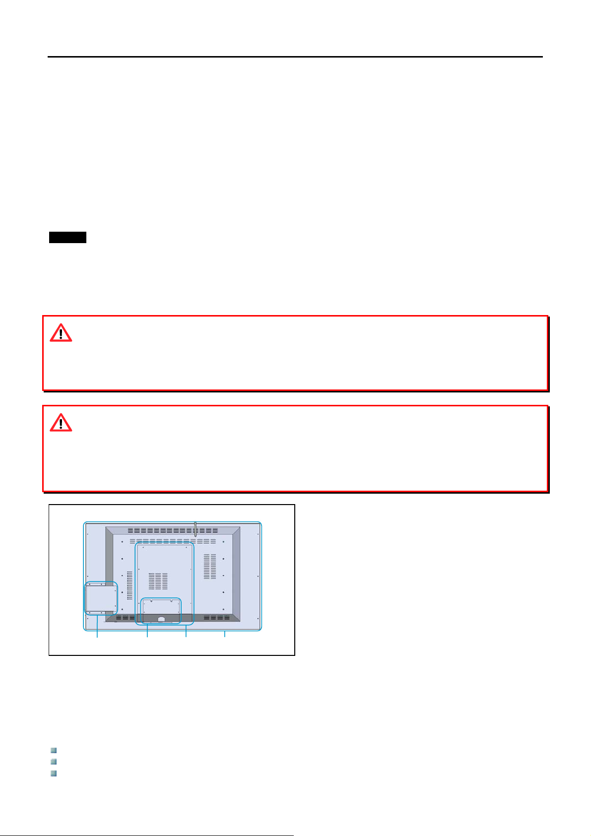
X Connector panel cover
Y Mainboard access panel
Z Rear panel
[ DVD drive housing
[
X
Y
Z
There are two rear panels on the back of the VM032, VM042(H) and VM047 series systems. The rear panel
(Y)in the center secured by 6 screws allows easy access to various computer components such as the
mainboard and hard disk drive and is referred to as the mainboard access panel. This removal of this panel
allows access to all major computer components and although the user will not normally need to remove this
panel, this panel is the only panel that needs to be removed for access to the mainboard and hard disk drive.
The large rear panel (Z) needs to be removed in order to gain access to the following components:
AD board
Mainboard power supply
SMPS for LCD panel
Page 33
Page 34
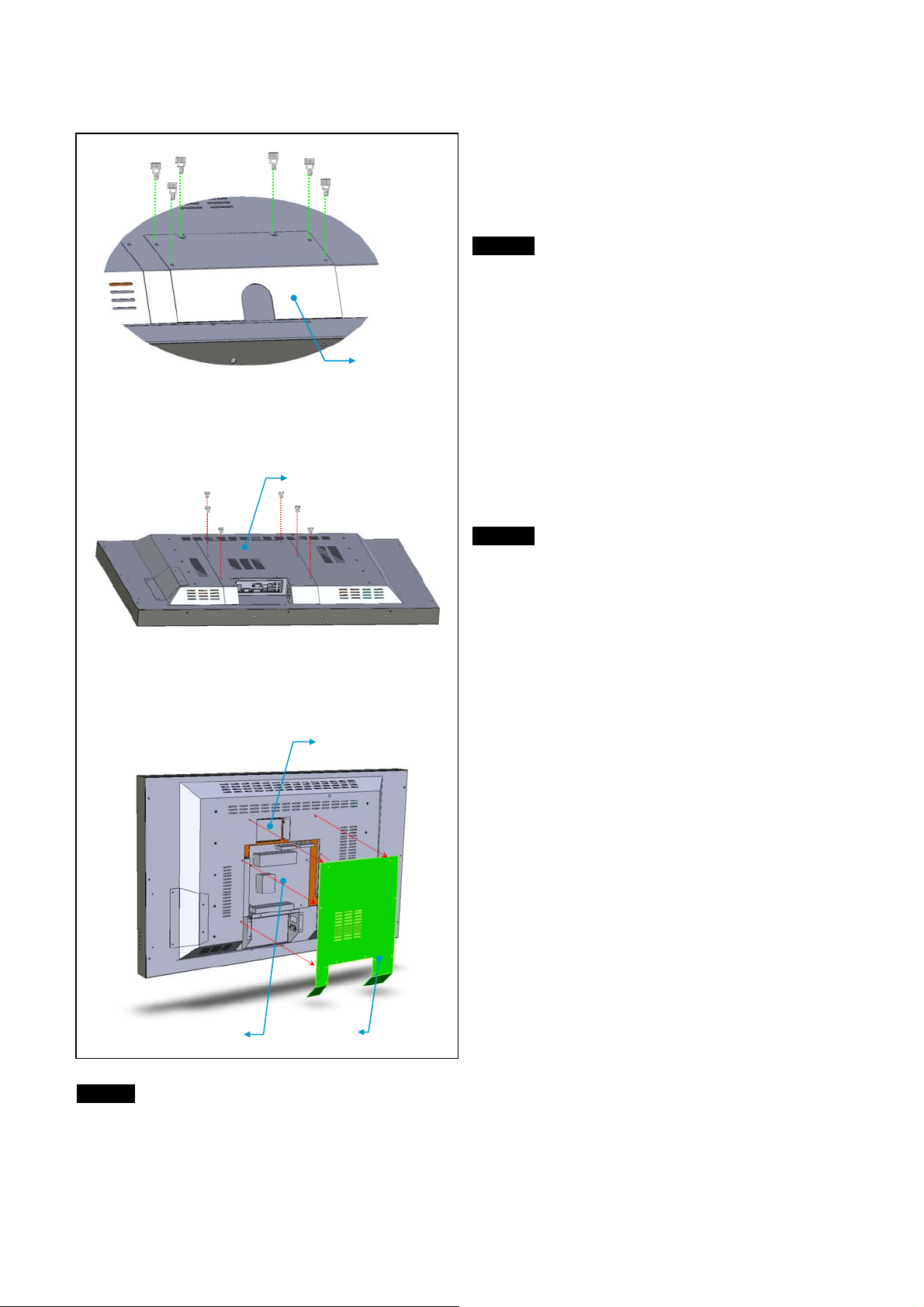
Mainboard Access Panel Removal
In order to remove the mainboard access panel and
gain access to various computer components, the
connector panel cover (X) needs to be removed first.
Step 1
Unscrew 6 thumb screws holding the connector panel
cover. Remove the connector panel.
Connector
panel cover X
Mainboard
access panel Y
Hard Disk Drive
Mainboard
Mainboard
access panel
NOTE
PLEASE REMOVE THE CONNECTOR PANEL COVER (X) BEFORE ATTEMPTING TO REMOVE THE
MAINBOARD ACCESS PANEL (Y). Any attempt to remove the mainboard access panel without removing the
connector panel cover may damage the panels in doing so.
Step 2
Unscrew 6 screws holding the mainboard access
panel (Y) using a Philips screwdriver. Remove the
mainboard access panel to access the various
computer components inside.
After removing the mainboard access panel, you will
have access to the mainboard and hard disk drive.
Please see the section for component replacement for
procedures on hard disk drive replacement.
Page 34
Page 35
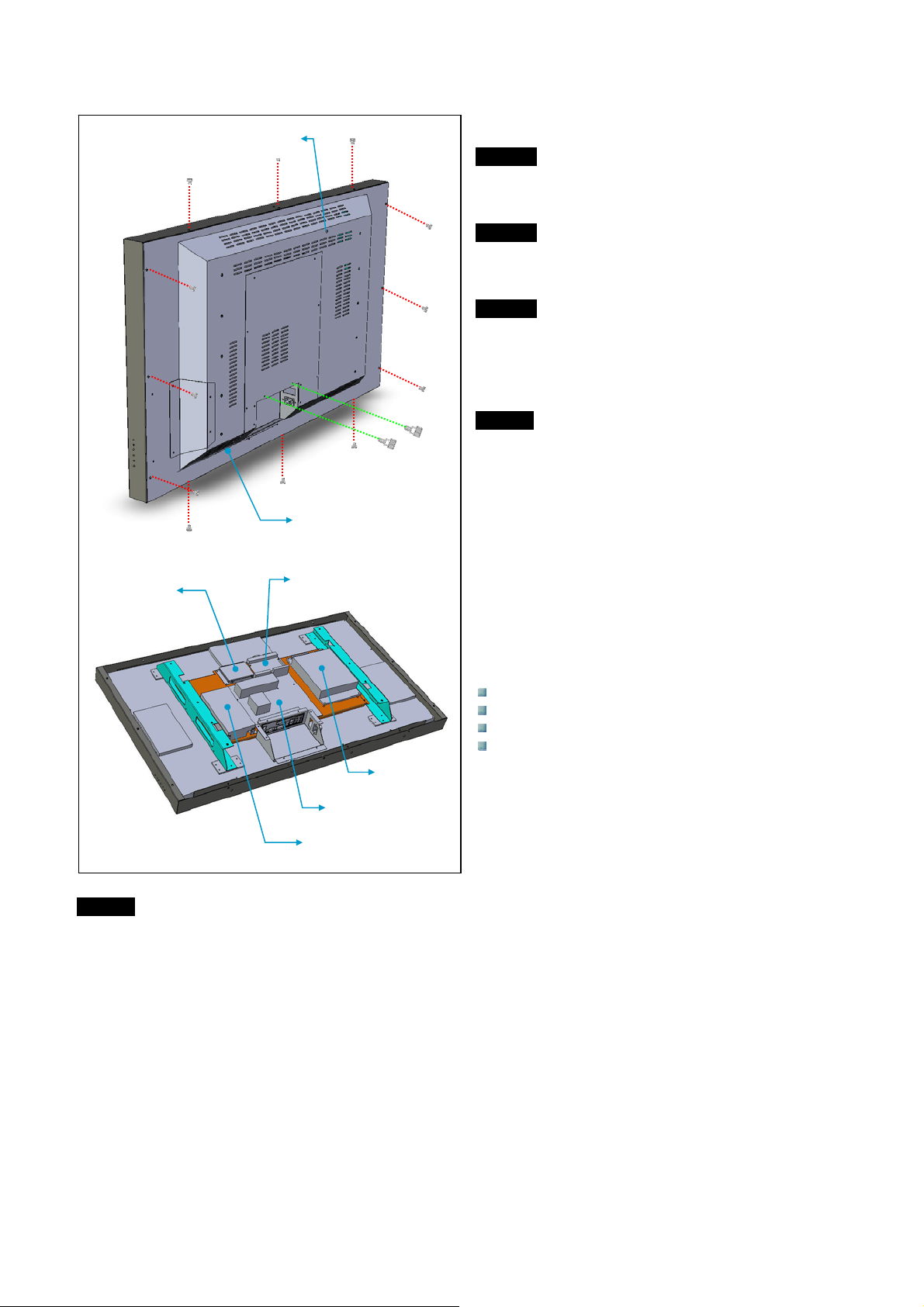
Rear Panel Removal
(
Wireless LAN antenna
Antenna not shown)
Rear panel Z
Hard disk drive
AD board
SMPS
Mainboard
PC Power Supply
NOTE
Be sure to lay the unit flat facing the floor before removing the rear panel. (The mainboard access panel will be
attached to the rear panel when it is removed.)
To remove the rear panel, follow the following steps.
Step 1
Unscrew the wireless LAN antenna located on the
rear panel.
Step 2
Remove 2 thumb screws holding the connector panel
cover.
Step 3
Using a Philips screwdriver, unscrew the 12 screws
holding the large rear panel as shown in the drawing
on the left.
NOTE
Be sure to remove any wall mount before proceeding
with the removal of the rear panel.
The following components are accessible once the
large rear panel ([) has been removed.
Mainboard
Hard disk drive
SMPS
PC power supply
Page 35
Page 36
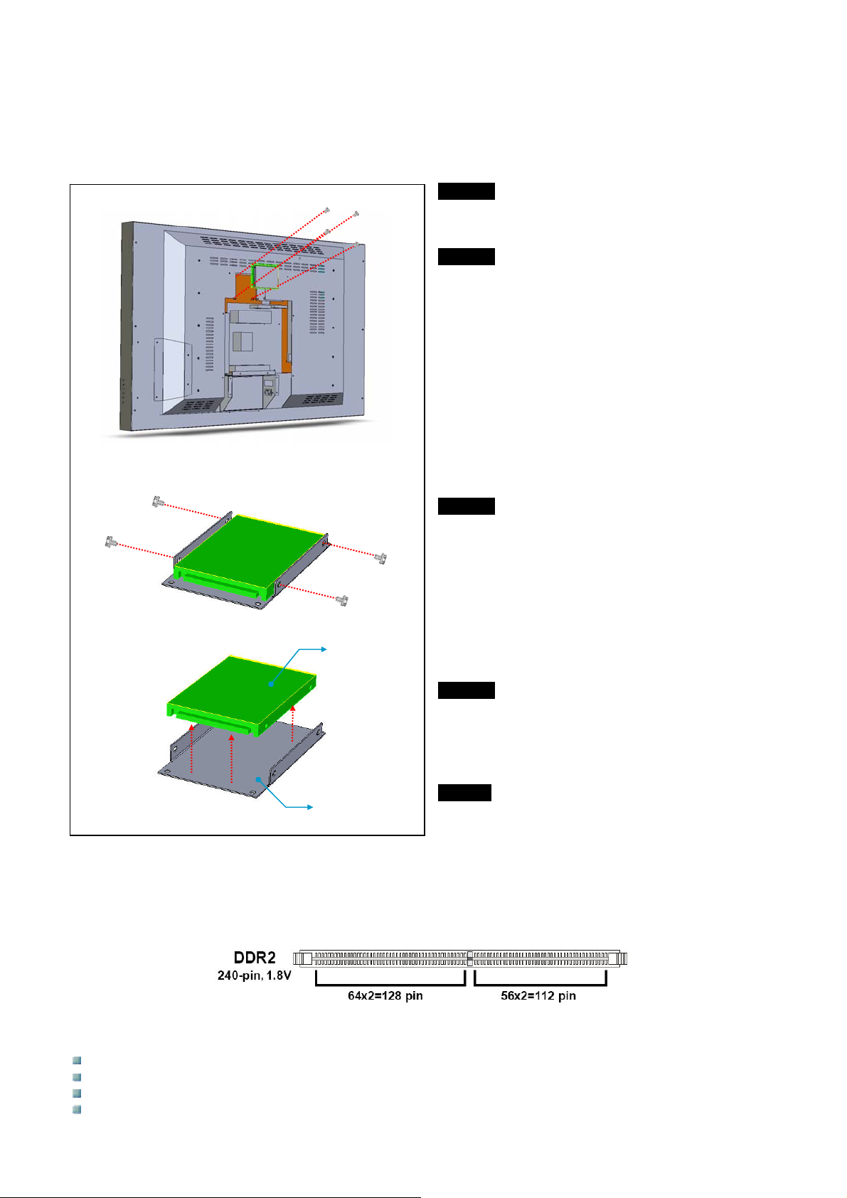
Component Replacements
The following sections cover the replacement procedures for various components inside the VM032, VM042(H)
and VM047 series monitors. Only qualified personnel should perform the replacement work.
Hark Disk Drive Replacement
Step 1
Remove the mainboard access panel following the
procedures in the previous section.
Step 2
Using a Philips screwdriver, unscrew 4 screws from
the protective housing that holds the hard disk drive.
Once the screws have been removed, lift out the
entire hard disk drive assembly.
Step 3
Using a Philips screwdriver, unscrew the 4 screws
holding the hard disk drive as shown in the drawing
on the left. Once the screws have been removed,
remove the rubber rings holding the hard disk drive in
place. (Be sure to keep the rubber rings in safe place
after removal.)
Hard disk drive
Protective Housing
Memory Module Replacement
The DIMM slots located on the mainboard are used for memory modules. (Please refer to the section on
‘Internal Peripheral Device Connectors’ in previous section to locate the DIMM slots on the mainboard.)
Step 4
Remove the hard disk drive from the protective
housing.
NOTE
Repeat the above procedures in reverse to install the
hard disk drive.
The following types of memory modules can be used:
PC4300 DDR2 RAM (DDR-533)
PC5300 DDR2 RAM (DDR-667)
PC6400 DDR2 RAM (DDR-800)
PC8500 DDR2 RAM (DDR-1066)
Page 36
Page 37
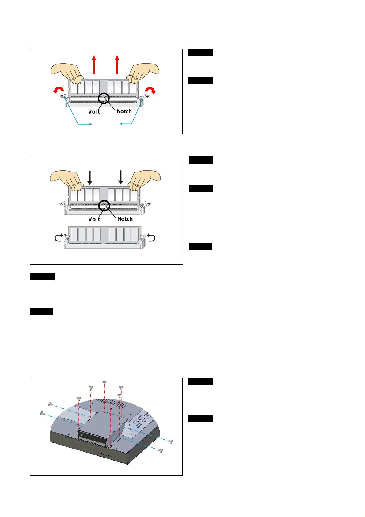
To remove the memory module from the DIMM slot(s), follow the following steps.
Step 1
Flip the plastic clips at each side of the DIMM slot
outward and the memory module will pop up.
Step 2
Hold the memory module with both hands and bring it
upward to remove it completely from the DIMM slot.
Plastic clips
To install a new memory module, follow the following steps.
Step 1
Flip the plastic clips at each side of the DIMM slot
outward before installing the memory module.
Step 2
Hold the memory module with both hands and insert
it vertically into the DIMM slot. Then push it in until
the golden finger on the memory module is deeply
inserted in the DIMM slot (The golden finger can
barely be seen if the memory module is properly
inserted in the DIMM slot).
NOTE
The memory module has only one notch in the center
and will only fit in the right orientation.
Step 3
The plastic clips at each side of the DIMM slot will automatically close when the memory module is inserted, but
make sure the plastic clips have completely closed and locked in place.
NOTE
1) DDR2 memory modules are not interchangeable with DDR memory modules and they are not backwards
compatible. You should always install DDR2 memory modules in DDR2 DIMM slots.
2) To enable successful system boot-up, always insert the memory modules into the DIMM1 slot first.
DVD Drive Replacement
In order to remove the DVD drive, follow the instructions below.
Step 1
Using a Philips screwdriver, unscrew 6 screws
holding the DVD drive housing from the main rear
panel.
Step 2
With the DVD drive housing still in place, unscrew 4
screws holding the DVD drive itself from the DVD
drive housing using a Philips screwdriver. (Do not
remove the DVD drive housing when unscrewing
since the DVD drive is still connected internally to the
mainboard.)
Page 37
Page 38
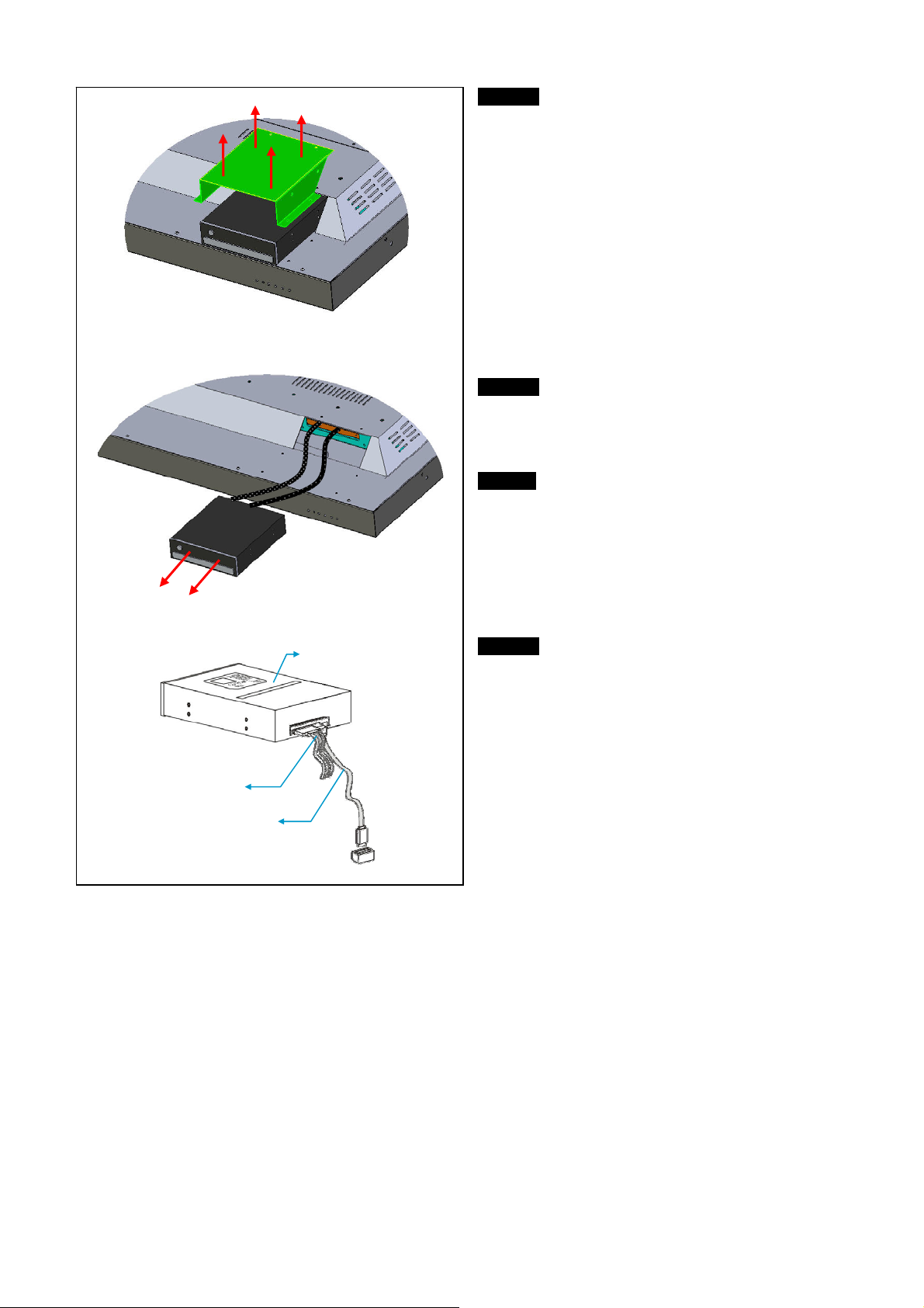
Power cable
SATA cable
DVD drive
Step 3
Once all the screws in steps 1 and 2 have been
removed, lift the DVD drive housing and remove it
from the main rear panel.
Step 4
Pull out the DVD drive carefully from its position. The
DVD drive will have two cables (power and SATA
cables) connected to it.
NOTE
Do not exert too much force when pulling out the
DVD drive since the length of the cables are limited
and too much force can damage the cables and/or
connectors and the cables may also come loose from
the mainboard.
Step 5
Looking at the rear of the DVD drive, remove the
power cable and SATA cable from the DVD drive.
Page 38
Page 39
BBIIOOSS SSeettuupp
Entering Setup
Power on the computer and unit using the main power switch and the system will begin the POST (Power On
Self Test) process. When the message below appears on the screen, press <DEL> key to enter the setup menu.
Press DEL to enter SETUP
If the message appears before you respond and you still wish to enter Setup, restart the system by turning it
OFF and On. You may also restart the system by simultaneously pressing <Ctrl>, <ALT>, and <Delete> keys.
Control Keys
<u> Move to the previous item
<v> Move to the next item
<s> Move to the item in the left hand
<t> Move to the item in the right hand
<Enter> Select the item
<ESC>
<+/Page Up> Increase the numeric value or make changes
<-/Page Down> Decrease the numeric value or make changes
<F6> Load optimized default values
<F10> Save all the CMOS changes and exit
Getting Help
After entering the Setup menu, the first menu you will see is the Main Menu.
Main Menu
The main menu lists the setup functions you can make changes to. You can use the arrow keys (u/v/s/t) to
select the item. The on-line description of the highlighted setup function is displayed at the bottom of the screen.
Sub-Menu
If you find a right pointer symbol appears to the left of certain fields that means a sub-menu can be launched
from this field. A sub-menu contains additional options for a field parameter. You can use arrow keys () to
highlight the field and you can press <Enter> to call up the sub-menu. Then you can use the control keys to
enter the values and move from field to field within a sub-menu. If you want to return to the main menu, just
press the <ESC> key.
General Help <F1>
The BIOS setup program provides a General Help screen. You can call up this screen from any menu by simply
pressing <F1>. The Help screen lists the appropriate keys to use and the possible sections for the highlighted
item. Press <ESC> to exit the Help screen.
Jumps to the Exit menu or returns to the main menu from a submenu
Page 39
Page 40
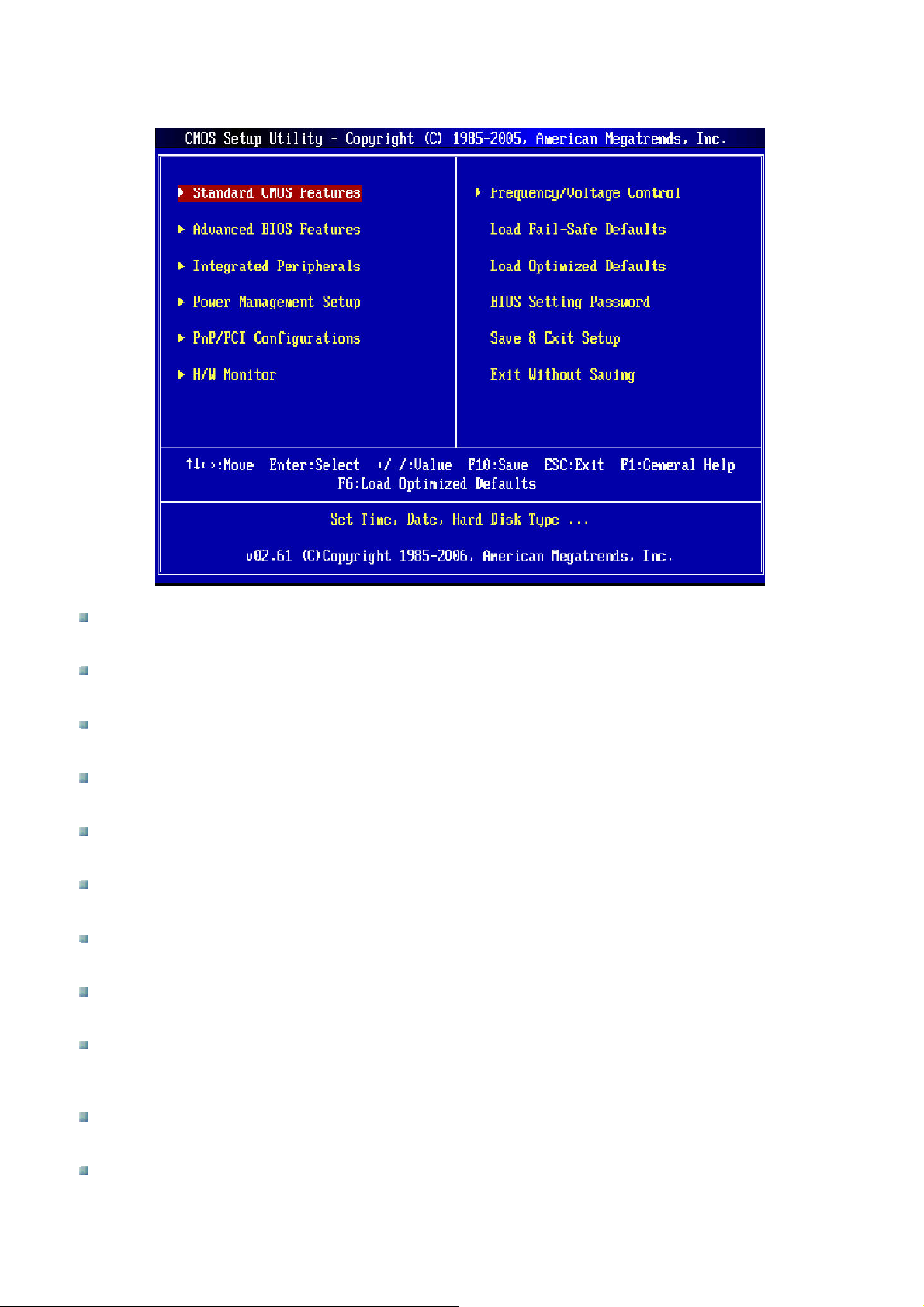
The Main Menu
Standard CMOS Features
Use this menu for basic system configurations such as time, date, etc.
Advanced BIOS Features
Use this menu to setup the items of AMI
®
special enhanced features.
Integrated Peripherals
Use this menu to specify your settings for integrated peripherals.
Power Management Setup
Use this menu to specify your settings for power management
PnP/PCI Configurations
This entry appears if your system supports PnP/PCI.
H/W Monitor
This entry shows your PC health status
Frequency/Voltage Control
Use this menu to specify your settings for frequency/voltage control and overclocking.
Load Fail-Safe Defaults
Use this menu to load the default values set by the BIOS vendor for stable system performance.
Load Optimized Defaults
Use this menu to load the default values set by the mainboard manufacturer specifically for optimal
performance of the mainboard.
BIOS Setting Password
Use this menu to set the password for BIOS.
Save & Exit Setup
Save changes to CMOS and exit setup.
Page 40
Page 41
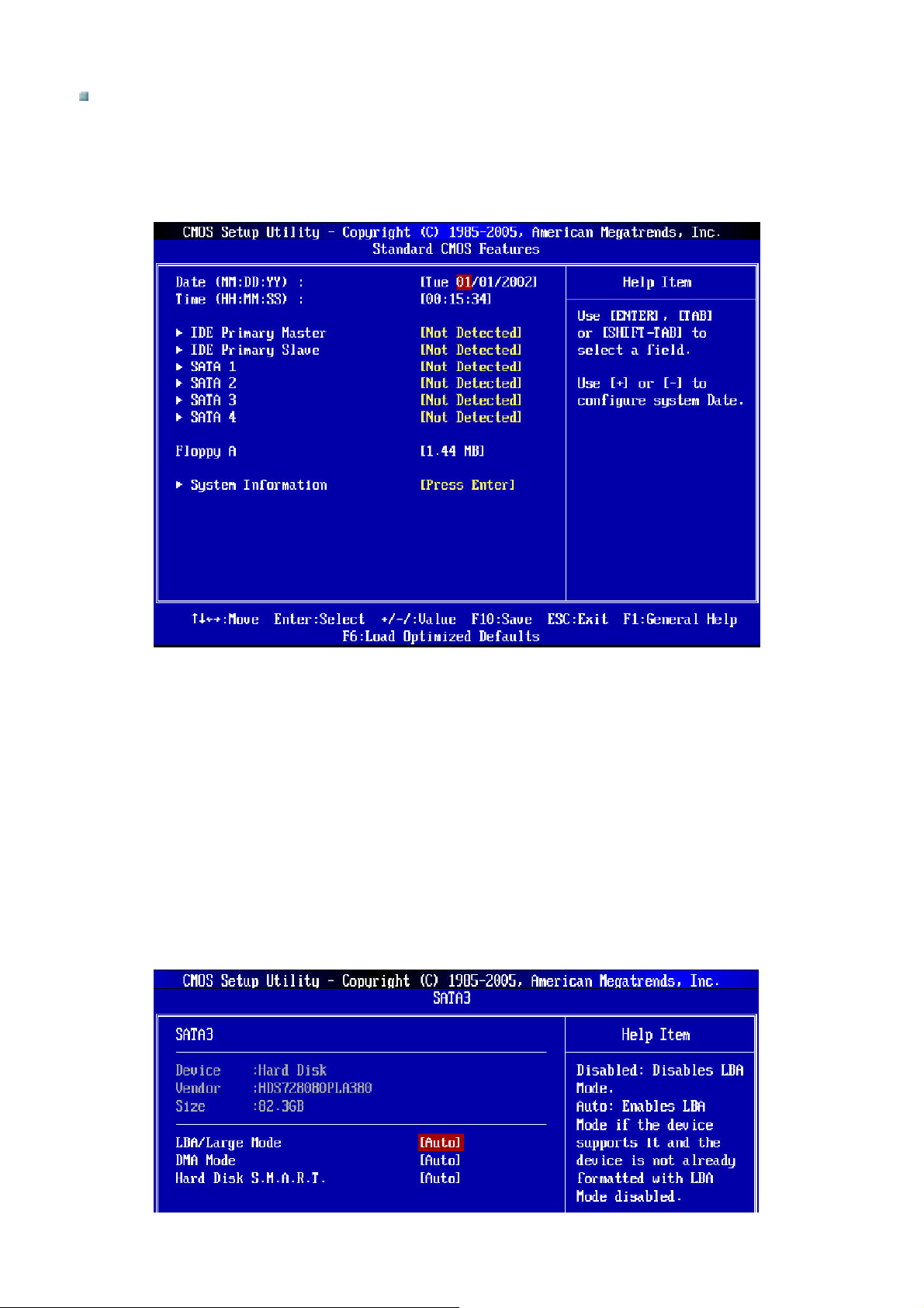
Exit Without Saving
Abandon all changes and exit setup.
Standard CMOS Features
The items in Standard CMOS Features Menu include some basic setup items. Use the arrow keys to highlight
the item and then use the <PgUp> or <PgDn> keys to select the value you want in each item.
Date (MM:DD:YY)
This allows you to set the system to the date that you want (usually the current date). The format is <day>
<month> <date> <year>.
Day
Month
Date
Year
Day of the week, from Sun to Sat, determined by BIOS. Read-only.
The month from Jan to Dec.
The date from 1 to 31 can be keyed in by numeric keys
The year can be adjusted by users.
Time (HH:MM:SS)
This allows you to set the system time that you want (usually the current time). The time format is <hour>
<minute> <second>.
IDE Primary Master/Slave, SATA 1~4
Press <Enter> to enter the sub-menu and the following screen appears.
Page 41
Page 42
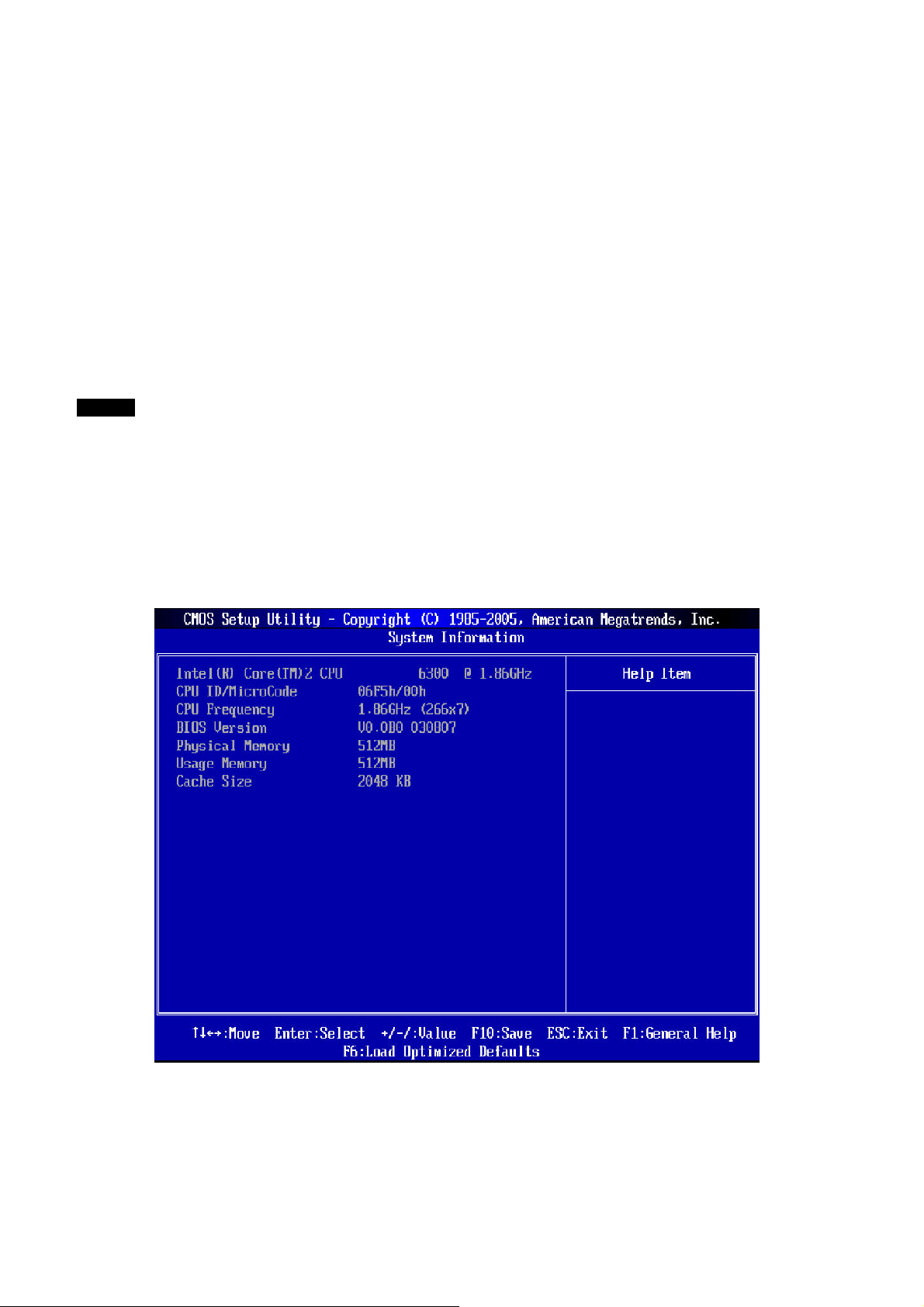
Device / Vendor / Size
Shows the device information that you connected to the SATA connectors.
LBA/Large Mode
This allows you to enable or disable the LBA Mode. Setting to Auto enables LBA mode if the device supports it
and the devices are not already formatted with LBA mode disabled.
DMA Mode
Selects the DMA mode.
Hard Disk S.M.A.R.T.
This allows you to activate the S.M.A.R.T. (Self-Monitoring Analysis & Reporting Technology) capability for the
hard disks. S.M.A.R.T. is a utility that monitors your disk status to predict hard disk failure. This gives you an
opportunity to move data from a hard disk that is going to fail to a safe place before the hard disk becomes
offline.
NOTE
IDE Primary Master/Slave and Serial-ATA 1/2/3/4 Channels appear when you connect the HD devices to the
IDE/SATA connectors on the mainboard.
Floppy A
This item allows you to set the type of floppy drives installed. Available options: [None], [360K, 5.25 in.], [1.2M,
5.25 in.], [720K, 3.5 in.], [1.44M, 3.5 in.], [2.88M, 3.5 in.].
System Information
Press <Enter> to enter the sub-menu and the following screen appears.
This sub-menu shows the CPU information, BIOS version and memory status of your system (read-only).
Page 42
Page 43
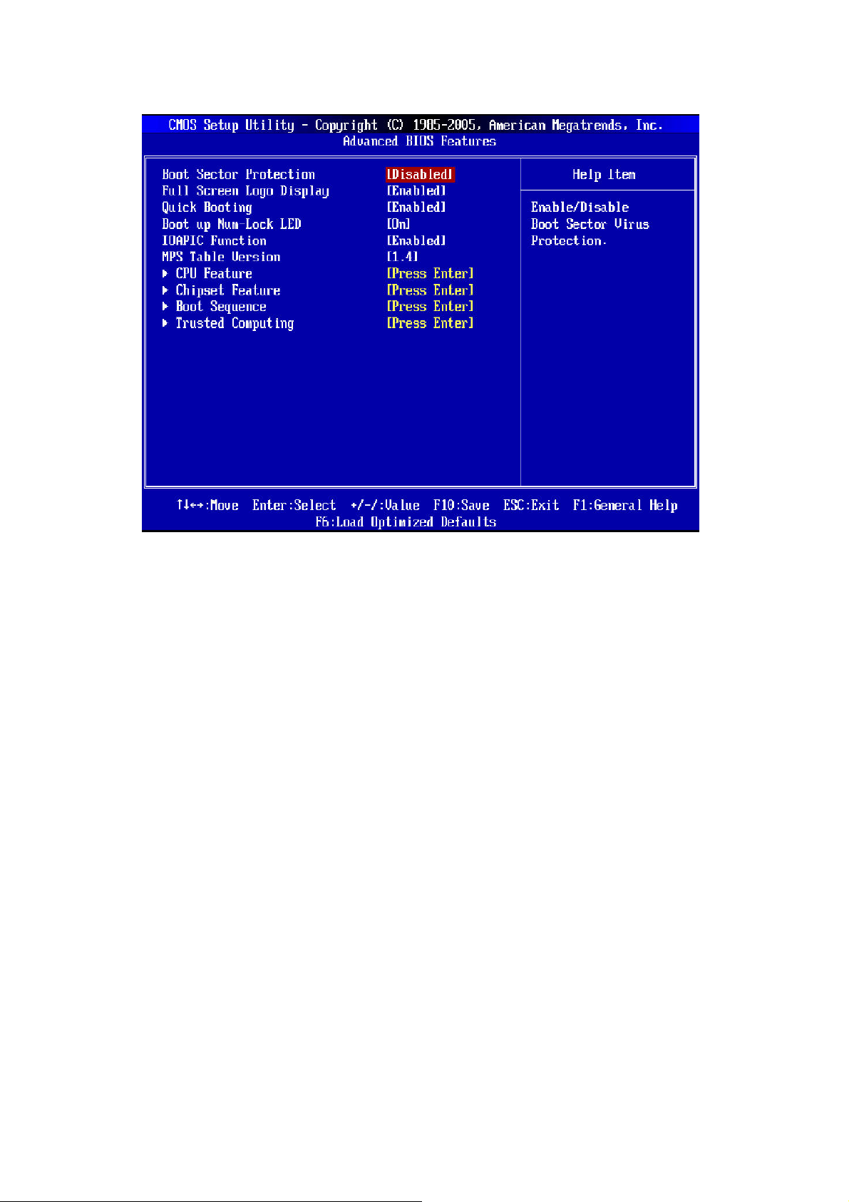
Advanced BIOS Features
Boot Sector Protection
This function protects the BIOS from accidental corruption by unauthorized users or computer viruses. When
enabled, the BIOS’ data cannot be changed when attempting to update the BIOS with a Flash utility. To
successfully update the BIOS, you will need to disable this Flash BIOS Protection function.
You should enable this function at all times. The only time when you need to disable it is when you want to
update the BIOS. After updating the BIOS, you should immediately re-enable it to protect it against viruses.
Full Screen LOGO Display
This item enables you to show the company logo on the bootup screen. Settings are:
[Enabled]
[Disabled]
Shows a still image (logo) on the full screen at boot.
Shows the POST messages at boot.
Quick Booting
Setting this item to [Enabled] allows the system to boot within 10 seconds since it will skip some check items.
Boot Up Num-Lock LED
This setting is to set the Num Lock status when the system is powered on. Setting to [On] will turn on the Num
Lock key when the system is powered on. Setting to [Off] will allow users to use the arrow keys on the numeric
keypad.
IOAPIC Function
This field is used to enable or disable the APIC (Advanced Programmable Interrupt Controller). Due to
compliance with PC2001 design guide, the system is able to run in APIC mode. Enabling APIC mode will
expand available IRQ resources for the system.
MPS Table Version
This field allows you to select which MPS (Multi-Processor Specification) version to be used for the operating
system. You need to select the MPS version supported by your operating system. To find out which version to
use, consult the vendor of your operating system.
Page 43
Page 44
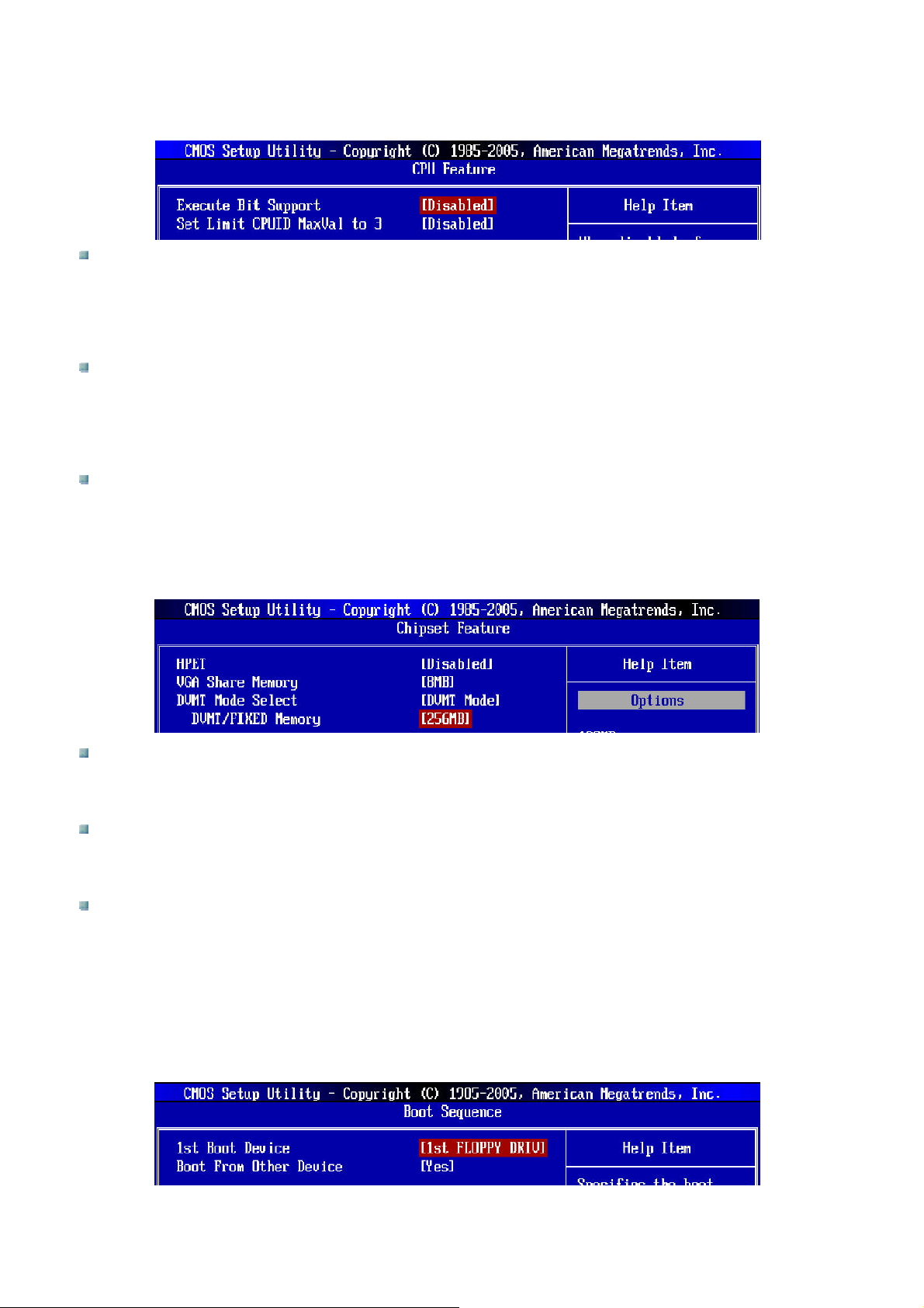
CPU Feature
Press <Enter> to enter the sub-menu and the following screen appears:
Hyper-Threading Technology
This field appears only when the CPU supports Hyper-Threading. The processor uses Hyper-Threading
technology to increase transaction rates and reduces end-user response times. The technology treats the
two cores inside the processor as two logical processors that can execute instructions simultaneously. In
this way, the processor will use only one core to execute the instructions.
Execute Bit Support
Intel’s Execute Disable Bit functionality can prevent certain classes of malicious “buffer overflow” attacks
when combined with a supporting operating system. This functionality allows the processor to classify areas
in memory by where application code can execute and where it cannot. When a malicious worm attempts to
insert code in the buffer, the processor disables code execution, preventing damage or worm propagation.
Set Limit CPUID MaxVal to 3
The Max CPUID Value Limit is designed to limit the listed speed of the processor to older operating
systems.
Chipset Feature
Press <Enter> to enter the sub-menu and the following screen appears:
HPET
The HPET (High Precision Event Timers) is a component that is part of the chipset. You can enable it and it
will provide you with the means to get to it via the various ACPI methods.
VGA Share Memory Size
The system shares memory to the onboard VGA card. This setting controls the exact memory size shared
to the VGA card.
DVMT Mode Select
This item allows you to set the mode for the graphics core.
[Fixed Mode], a fixed-size fragment of the system memory is allocated to the graphics core. It can only be
used by the graphics core.
[DVMT Mode], the driver of the graphics core uses the system memory like any other OS component or
application does.
Boot Sequence
Press <Enter> to enter the sub-menu and the following screen appears:
Page 44
Page 45
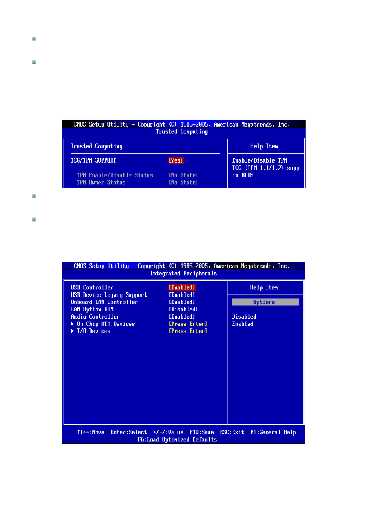
1st Boot Device
This allows you to set the first boot device when BIOS attempts to load the disk operating system.
Boot From Other Device
Setting this option to [Yes] allows the system to try to boot from other device. If the system fails to boot from
this device, it will attempt to boot from the selected first boot device, second boot device then finally the
third boot device.
Trusted Computing
Press <Enter> to enter the sub-menu and the following screen appears:
TCG/TPM Support
This field is used to enable or disable TPM (Trusted Platform Module) support in BIOS.
TPM Enable/Disable Status, TPM Owner Status
These items show the status of TPM (read-only).
Integrated Peripherals
USB Controller
This setting allows you to enable/disable the onboard USB controller.
USB Device Legacy Support
Select [Enabled] if you need to use a USB-interfaced device in the operating system.
Page 45
Page 46
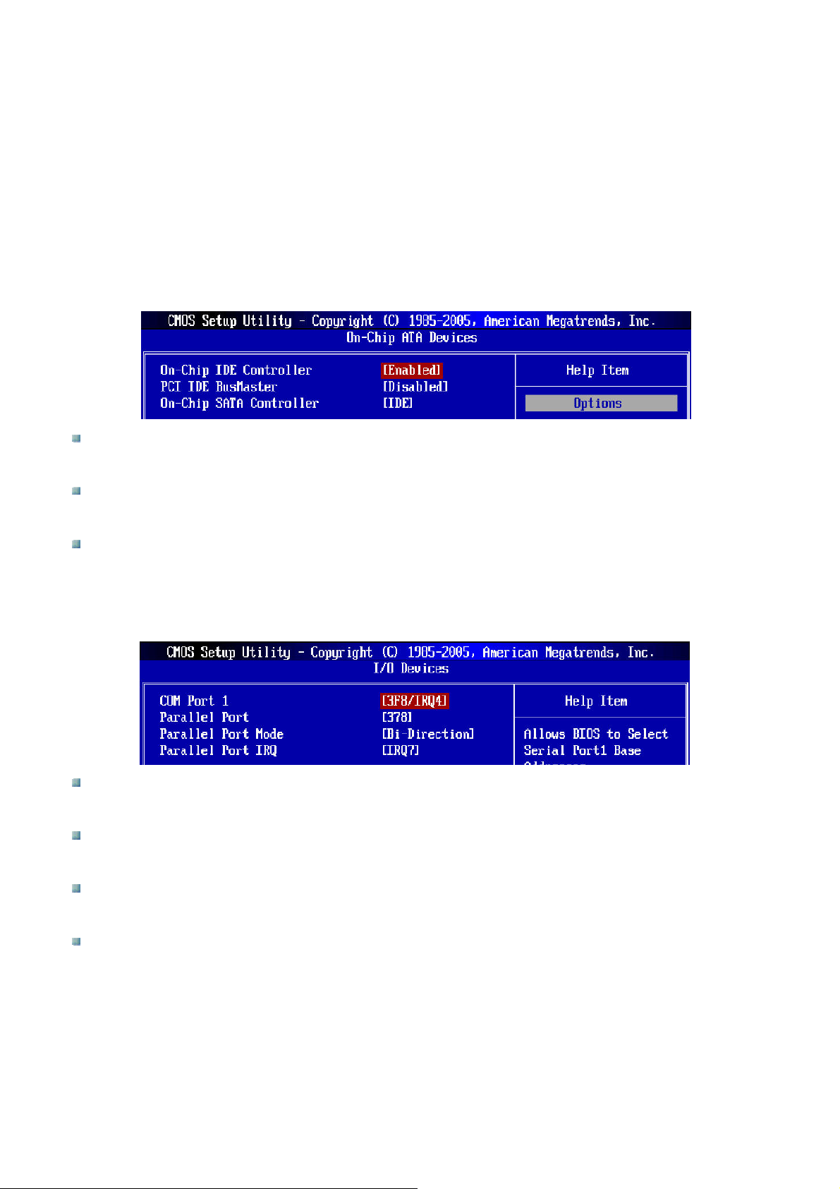
Onboard LAN Controller
This item is used to enable/disable the onboard LAN controller.
LAN Option ROM
This item is used to decide whether to invoke the Boot ROM of the LAN controller.
Audio Controller
This setting is used to enable/disable the onboard audio controller.
On-Chip ATA Devices
Press <Enter> to enter the sub-menu and the following screen appears:
On-Chip IDE Controller
These items allow users to enable or disable the IDE controller.
PCI IDE BusMaster
This item allows you to enable/disable BIOS to use PCI busmastering for reading/writing to IDE drives.
On-Chip SATA Controller
These items allow users to enable or disable the SATA controller.
I/O Devices
Press <Enter> to enter the sub-menu and the following screen appears:
COM Port 1
Select an address and corresponding interrupt for the first serial port.
Parallel Port
This item allows you to set the parallel port.
Parallel Port Mode
This item allows you to select the parallel port mode.
Parallel IRQ
This item allows you to set parallel IRQ.
Page 46
Page 47
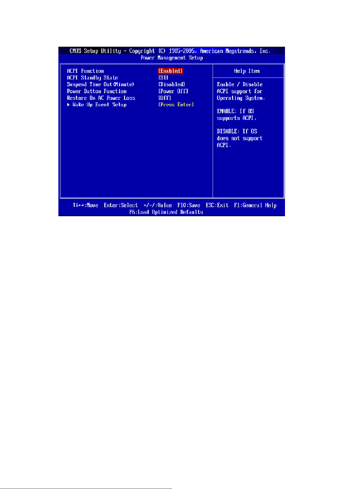
Power Management Setup
ACPI Function
This item is used to activate the ACPI (Advanced Configuration and Power Management Interface) Function. If
your operating system is ACPI-aware, such as Windows 2000/SP, select [Enabled].
ACPI Standby State
This item specifies the power saving modes for ACPI function. If your operating system supports ACPI, such as
Windows 2000/XP, you can choose to enter the Standby mode in S1 (POS) or S3 (STR) fashion through the
setting of this field. Settings are:
[S1]
[S3]
The S1 sleep mode is a low power state. In this state, no system context
is lost (CPU or chipset) and hardware maintains all system context.
The S3 sleep mode is a lower power state where the information of
system configuration and open application/files is saved to main memory
that remains powered while most other hardware components turn off to
save energy. The information is stored in memory will be used to restore
the system when a “wake up” event occurs.
Suspend Time Out (Minute)
If system activity is not detected for the length of time specified in this field, all devices except CPU will be shut
off.
Power Button Function
This feature sets the function of the power button. Settings are:
[On/Off]
[Suspend]
The power button functions as normal power off button.
When you press the power button, the computer enters the suspend/sleep
mode, but if the button is pressed for more than four seconds, the
computer is turned off.
Restore On AC Power Loss
This item specifies whether your system will reboot after a power failure or interrupt occurs. Settings are:
[Off]
Always leaves the computer in the power off state.
Page 47
Page 48
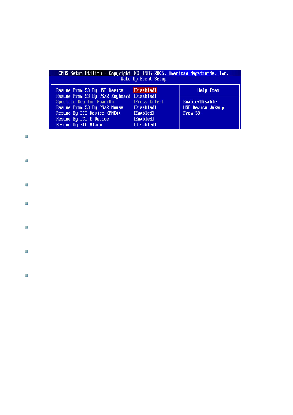
[On]
[Last State]
Always leaves the computer in the power on state.
Restores the system to the status before power failure or interrupt
occurred.
Wakeup Event Setup
Press <Enter> and the following sub-menu appears:
Resume From S3 By USB Device
This item allows the activity of the USB device to wake up the system from S3 (Suspend to RAM) sleep
state.
Resume From S3 By PS/2 Keyboard
This setting determines whether the system will be awakened from what power saving modes when input
signal of the PS/2 keyboard is detected.
Keyboard Power On Function
This item allows you to specify a key from the keyboard to power on the system.
Resume From S3 By PS/2 Mouse
This setting determines whether the system will be awakened from what power saving modes when input
signal of the PS/2 mouse is detected.
Resume By PCI Device (PME#)
When set to [Enabled], the feature allows your system to be awakened from the power saving modes
through any event on PME (Power Management Event).
Resume By PCI-E Device
When set to [Enabled], the feature allows your system to be awakened from the power saving modes
through any event on PCI-E device.
Resume By RTC Alarm
This field is used to enable or disable the feature of booting up the system on a scheduled time/date.
Page 48
Page 49
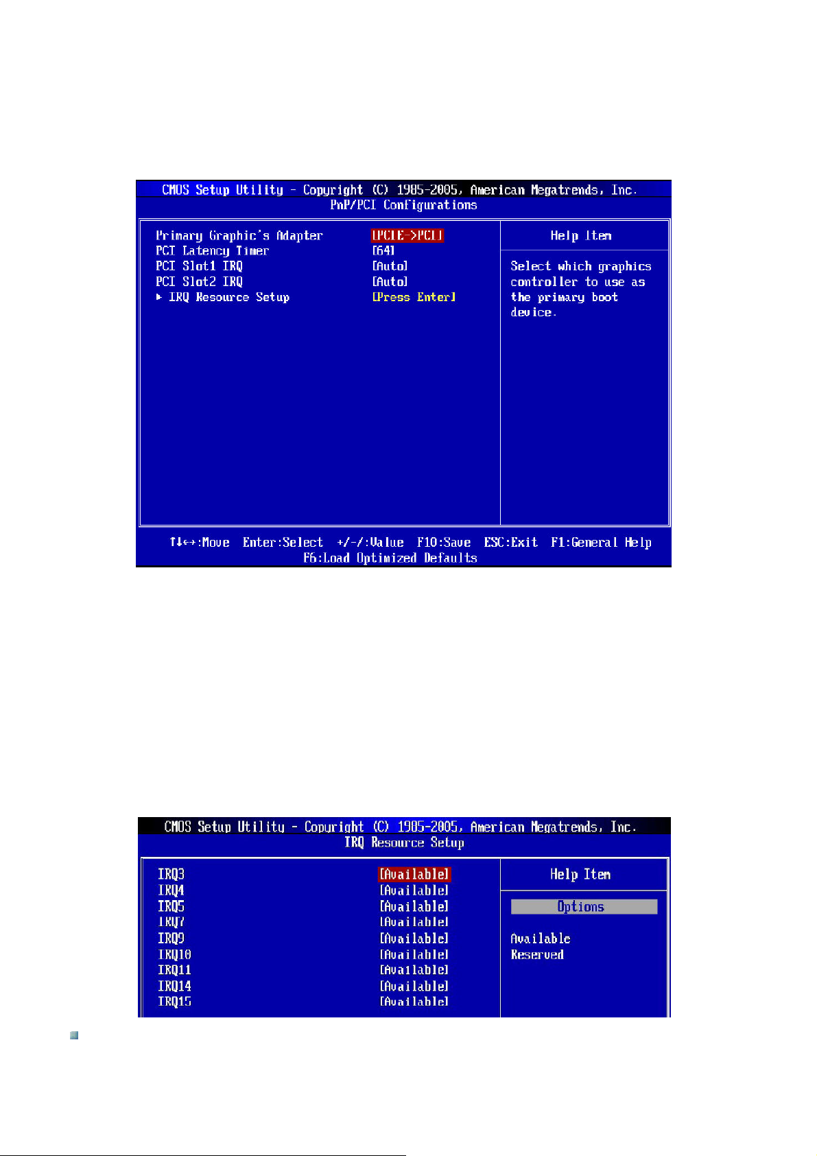
PNP/PCI Configurations
This section describes configuring the PCI bus system and PnP (Plug & Play) feature. PCI, or Peripheral
Component Interconnect, is a system which allows I/O devices to operate at speeds nearing the speed of the
CPU itself uses when communicating with its special components. This section covers some very technical
items and it is strongly recommended that only experienced users make any changes to the default settings.
Primary Graphic’s Adapter
This setting specifies which graphics card is your primary graphics adapter.
PCI Latency Timer
This item controls how long each PCI device can hold the bus before another takes over. When set to higher
values, every PCI device can conduct transactions for a longer time and thus improve the effective PCI
bandwidth. For better PCI performance, you should set the item to higher values.
PCI Slot 1/2 IRQ
These items specify the IRQ line for each PCI slot.
IRQ Resource Setup
Press <Enter> to enter the sub-menu and the following screen appears:
IRQ 3/4/5/7/9/10/11/14/15
These items specify the bus where the specified IRQ line is used. The settings determines if AMIBIOS
should remove an IRQ from the pool of available IRQs passed to devices that are configurable by the
Page 49
Page 50
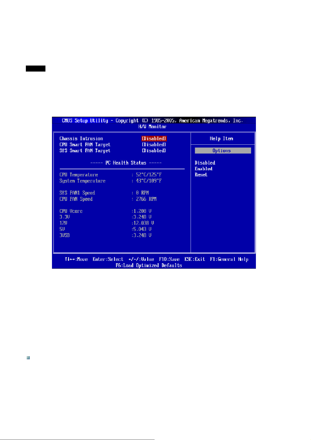
system BIOS. The available IRQ pool is determined by reading the ESCD NVRAM. If more IRQs must be
removed from the IRQ pool, the end user can use these settings to reserve the IRQ by assigning a
[Reserved] setting to it. Onboard I/O is configured by AMIBIOS. All IRQs used by onboard I/O are
configured as [Available]. If all IRQs are set to [Reserved], and IRQ 14/15 are allocated to the onboard PCI
IDE, IRQ 9 will still be available for PCI and PnP devices.
NOTE
IRQ (interrupt Request) lines are system resources allocated to I/O devices. When an I/O device needs to gain
attention of the operating system, it signals this by causing an IRQ to occur. After receiving the signal, when the
operating system ready, the system will interrupt itself and perform the service required by the I/O device.
H/W Monitor
Chassis Intrusion
The field enables or disables the feature of recording the chassis intrusion status and issuing a warning
message if the chassis is once opened. To clear the warning message, set the field to [Reset]. The setting of
the field will automatically return to [Enabled] later.
CPU/SYS Smart Fan Target
The mainboard provides the Smart Fan function which can control the CPU/System fan speed automatically
depending on the current temperature to keep it with in a specific range. You can select a fan target value here.
If the current CPU/System fan temperatures reach the target value, the smart fan function will be activated. It
provides several selections to speed up or cool down automatically.
PC Health Status
CPU/System Temperature, CPU FAN/SYS FAN1 Speed, CPU Vcore, 3.3V, 5V, 12V, 3VSB
These items display the current status of all the monitored hardware devices/components such as CPU
voltage, temperatures and all fans’ speeds.
Page 50
Page 51
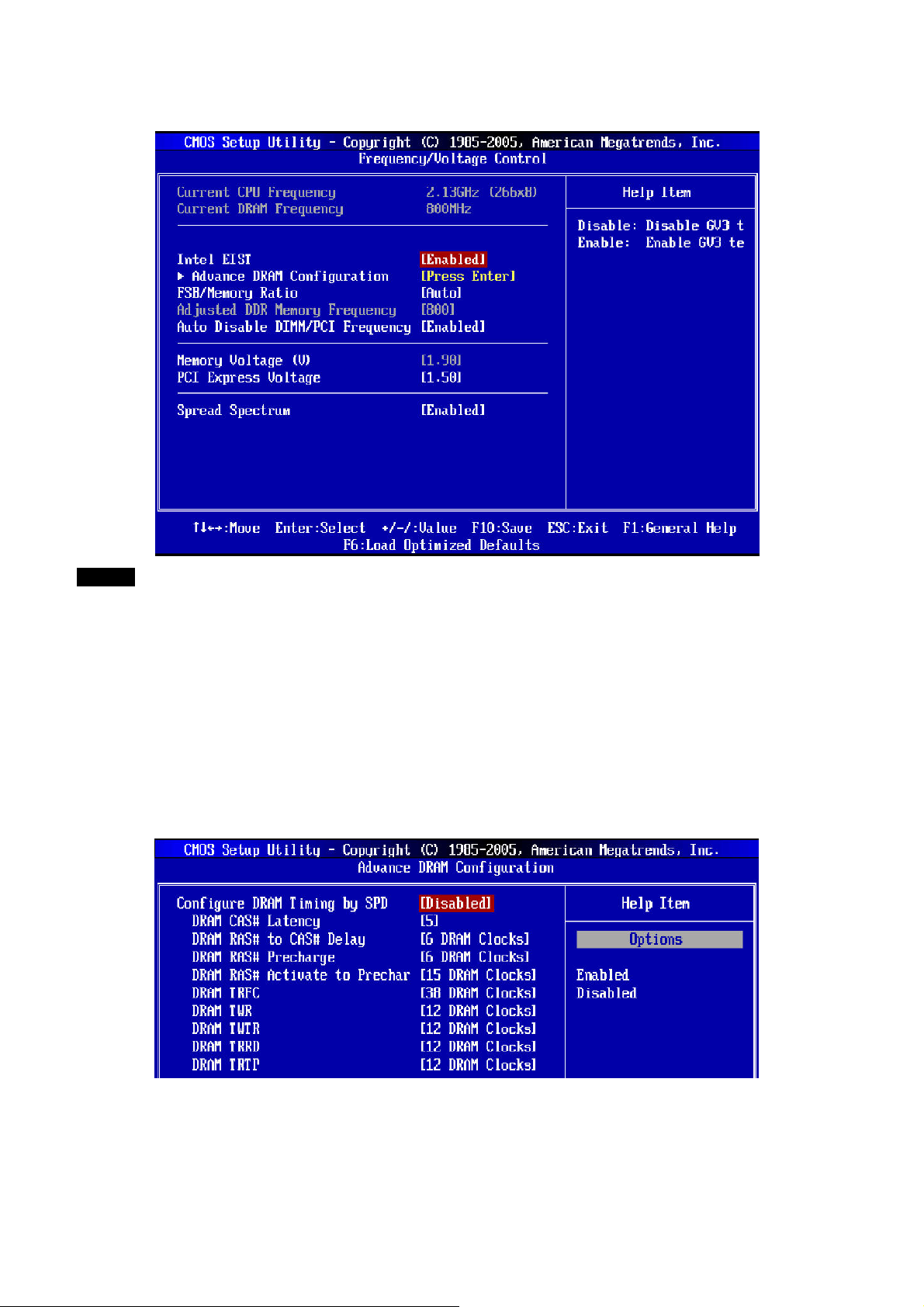
Frequency/Voltage Control
NOTE
Do NOT change these settings unless you are familiar with the chipset.
Current CPU/DRAM Frequency
These items show the current clocks of CPU and Memory speed. Read-only.
Intel® EIST
The Enhanced Intel® SpeedStep Technology allows you to set the performance level of the microprocessor
whether the computer is running on battery or AC power. This field will appear after you installed the CPU which
supports speedstep technology.
Advanced DRAM Configuration
Press <Enter> to enter the sub-menu and the following screen appears:
Configuration of DRAM Timing by SPD
Setting to [Enabled] enables DRAM CAS# Latency to be automatically determined by BIOS based on the
configurations of the SPD (Serial Presence Detect) EEPROM on the DRAM module.
Page 51
Page 52

DRAM CAS# Latency
When the Configuration DRAM Timing by SPD sets to [Disabled], the field is adjustable. This controls the
CAS latency, which determines the timing delay (in clock cycles) before SDRAM starts a read command
after receiving it.
DRAM RAS# to CAS# Delay
When the Configuration DRAM Timing by SPD sets to [Disabled], the field is adjustable. When DRAM is
refreshed, both rows and columns are addressed separately. This setup item allows you to determine the
timing of the transition from RAS (row address strobe) to CAS (column address strobe). The smaller the
clock cycles, the faster the DRAM performance.
DRAM RAS# Precharge
When the Configuration DRAM Timing by SPD sets to [Disabled], this field is adjustable. This field is
adjustable. This setting controls the number of cycles for Row Address Strobe (RAS) to be allowed for
precharge. If insufficient time is allowed for the RAS to accumulate its charge before DRAM refresh, refresh
may be incomplete and DRAM may fail to retain data. This item applies only when synchronous DRAM is
installed in the system.
DRAM RAS# Activate to Precharge
When the Configuration DRAM Timing by SPD sets to [Disabled], this field is adjustable. This field is
adjustable. This setting controls the number of cycles for Row Address Strobe (RAS) to be allowed for
precharge. If insufficient time is allowed for the RAS to accumulate its charge before DRAM refresh, refresh
may be incomplete and DRAM may fail to retain data. This item applies only when synchronous DRAM is
installed in the system.
DRAM TRFC
When the Configuration DRAM Timing by SPD sets to [Disabled], the field is adjustable. This setting
determines the time RFC takes to read from and write to a memory cell.
DRAM TWR
When the Configuration DRAM Timing by SPD sets to [Disabled], the field is adjustable. Minimum time
interval between end of write data burst and the start of a precharge command. Allows sense amplifiers to
restore data to cells.
DRAM TWTR
When the Configuration DRAM Timing by SPD sets to [Disabled], the field is adjustable. Minimum time
interval between end of write data burst and the start of a column-read command. It allows I/O gating to
overdrive sense amplifiers before read command starts.
DRAM TRRD
When the Configuration DRAM Timing by SPD sets to [Disabled], the field is adjustable. Specifies the
active-to-active delay of different banks. Time interval between a read and a precharge command.
DRAM TRTP
When the Configuration DRAM Timing by SPD sets to [Disabled], the field is adjustable. Time interval
between a read and a precharge command.
FSB/Memory Ratio
This item will allow you to adjust the FSB/Ratio of memory.
Adjusted DDR Memory Frequency
It shows the adjusted DDR memory frequency. Read-only.
Auto Disable DIMM/PCI Frequency
When set to [Enabled], the system will remove (turn off) clocks from empty DIMM and PCI slots to minimize the
electromagnetic interference (EMI).
Memory Voltage (V)
This item will allow you to adjust the Memory voltage.
Page 52
Page 53
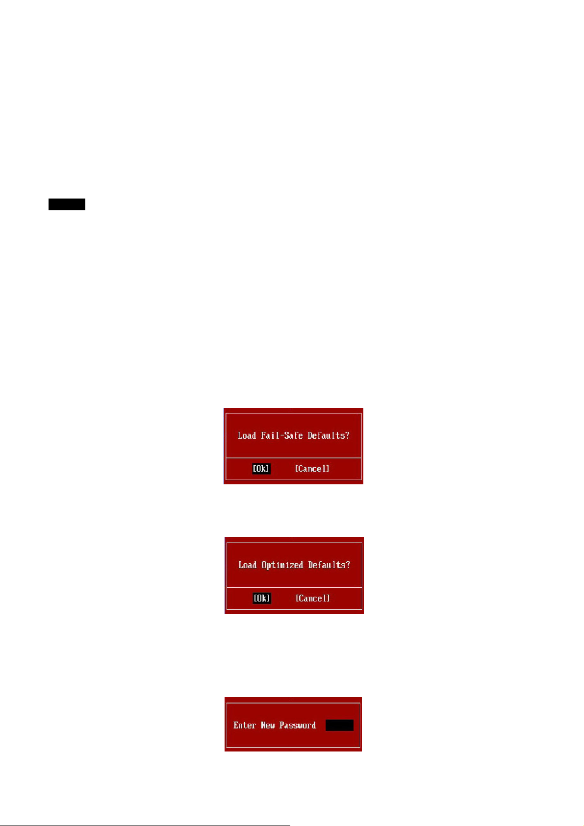
PCI Express Voltage
This item will allow you to adjust the PCI Express voltage.
Spread Spectrum
When the mainboard’s clock generator pulses, the extreme values (spikes) of the pulses create EMI
(Electromagnetic Interference). The Spread Spectrum function reduces the EMI generated by modulating the
pulses so that the spikes of the pulses are reduced to flatter curves. If you do not have any EMI problem, leave
the setting at Disabled for optimal system stability and performance. But if you are plagued by EMI, set to
Enabled for EMI reduction. Remember to disable Spread Spectrum if you are overclocking because even a
slighter jitter can introduce a temporary boost in clock speed which may just cause your overclocked processor
to lock up.
NOTE
1. If you do not have any EMI problem, leave the setting at [Disabled] for optimal system stability and
performance. Bit if you are plagued by EMI, select the value of Spread Spectrum for EMI reduction.
2. The greater the Spread Spectrum value is, the greater the EMI is reduced, and the system will become less
stable. For the most suitable Spread Spectrum value, please consult your local EMI regulation.
3. Remember to disable Spread Spectrum if you are overclocking because even a slight jitter can introduce a
temporary boost in clock speed which may just cause your overclocked processor to lock up.
Load Fail-Safe/Optimized Defaults
The two options on the main menu allow users to restore all of the BIOS settings to the default Fail-Safe or
Optimized values. The Optimized Defaults are the default values set by the mainboard manufacturer specifically
for optimal performance of the mainboard. The Fail-Safe Defaults are the default values set by the BIOS vendor
for stable system performance.
When you select Load Fail-Safe Defaults, a message appears as below:
Pressing [Ok] loads the BIOS default values for the most stable, minimal system performance.
When you select Load Optimized Defaults, a message as below appears:
Pressing [Ok] loads the default factory settings for optimal system performance.
BIOS Setting Password
When you select this function, a message as below will appear on the screen:
Page 53
Page 54

Type the password, up to six characters in length, and press <Enter>. The password typed now will replace any
previously set password from CMOS memory. You will be prompted to confirm the password. Retype the
password and press <Enter>. You may also press <ESC> to abort the selection and not enter a password.
To clear a set password, just press <Enter> when you are prompted to enter the password. A message will
show up confirming the password will be disabled. Once the password is disabled, the system will boot and you
can enter Setup without entering any password.
When a password has been set, you will be prompted to enter it every time you try to enter Setup. This prevents
an unauthorized perform from changing any part of your system configuration.
Page 54
Page 55
TTrroouubblleesshhoooottiinngg
Before requesting service, please check the following points.
If the problem persists, contact your local dealer or vendor.
Problem Cause Remedy
No picture
(Power indicator is lit)
No picture
(Power indicator is not lit)
Colors do not display properly. Loose VGA cable
Display power or screen turns off after
a short time.
Horizontal lines of static disturb the
picture.
Remote control does not work
A different input is selected.
Loose VGA cable
Computer standby mode
Loose power cord
Screen saver activation
Computer standby mode
The internal temperature of the display
is getting high.
Something is blocking the remote
control signal detector on the display.
The batteries in the remote control are
drained.
Using the On-Screen Display controls,
check the input selection.
Open the connector panel cover and
check the VGA cable connection.
Go to control panel in Windows and
check the power savings
configuration.
Check the power cord connection to
the power outlet.
Open the connector panel cover and
check the power cord connection.
Open the connector panel cover and
check the VGA cable connection.
Go to control panel in Windows and
check the screen saver configuration.
Go to control panel in Windows and
check the power savings
configuration.
Turn off the power and make sure the
air vents are not blocked, that there is
ample space for air to flow around the
display, and that the ventilation in the
room is working properly. When the
internal temperature returns to
normal, the display will operate
properly again.
Make sure no object is blocking the
remote control receiver located in the
front of the display.
Replace the batteries in the remote
control.
Page 55
Page 56

SSooffttwwaarree DDrriivveerrss
Mainboard Drivers
Mainboard INF Drivers
VGA Driver
Soundcard Driver
Network Driver
Additional Drivers
iMON Remote Control (Optional)
Optional Drivers
Page 56
 Loading...