

VIET-TRUNG CT-2000ES Instruction Manual

C.TY TNHH TỰ ĐỘNG HÓA VIỆT TRUNG 02413.281.181-0989.984.666
Introduction
Thank you for choosing the CT-2000ES inverter unit, this inverter unit is suitable for operating squirrel cage
induction motors. Please read this instruction manual carefully before actual usage in order to ensure proper
operation and suit your needs.
Table of Contents
1. Inspection upon receiving…………………………………………………………………………………..
2. Installation and Storage……………………………………………………
A. Installation ……………………………………………………………………………………………..
B. Storage…………………………………………………………………………………………………
C. Outline dimension……………………………………………………………………………………..
3. Application notes……………………………………………………………………………………………..
4. Block diagram and wring …………………………………………………………………………………..
A. Wiring of main and control circuit …………………………………………………………………...
B. Signal circuit……………………………………………………………
C. Connecting the power supply and the AC motor……………………
D. R.S.T. for Power source reactor………………………………………………………………….
E. Brake resistor standard of usage
F. Standard external connection diagram……………………………………………………….……
G. Control circuit specification…………………………………………..…………………………….
H. Terminal specifications……………………………………………………………………………..
5. Operation Test………………………………………………………………
6. Adjust and Function Specification………………………………..………………………………………
A. Keypad operation……………………………………………………………………………………
B. Display specification…………………………………………………………………………………
C. Keypad specification………………………………………………………………………………..
D. Function Code……………………………………………………………………………………….
7. Description of alarm display indications …………………………………
8. Troubleshooting………………………………………………………………………………………………
9. Maintenance and Inspection……………………………….………………………………………………
10. Standard Specification……………………………………………………………………………………..
A. 200V series 1 phase……………………………………………………………………….…………
B. 200V series 3 phase………………………………………………………………………………….
C. 400Vseries 3 phase…………………..………………………………………………………………
11. Function code Table……………………………………..………………………………………………
12. Modbus Address of Display Data….……………………………………
13. Series Communication User Manual..……………………………………………………………………
A. The physical link………………………………………………………………………………………
B. Data structure in communication…………………………………………………………………….
C. Function code in Modbus…………………………………………………………………………….
D. Error check generation……………………………………………………………………………….
E. Group & global broadcasting………………………………………………………………………...
2
………………………….. 2
2
2
3
4
4
4
……………………….. 4
………………………. 4
.. 5
……………………………………………………….. 5
. 6
. 7
. 8
……………………….... 9
.. 11
11
11
11
13
…………………………. 43
44
. 45
46
46
47
48
... 49
………………………….. 53
54
54
55
56
58
59
Website: www.viet-trung.com.vn Đ/c: 194- Nguyễn Trãi- Võ Cường-TP.Bắc Ninh
1

C.TY TNHH TỰ ĐỘNG HÓA VIỆT TRUNG 02413.281.181-0989.984.666
1. Inspection upon receiving
1
A. Check that the model, the capacity and power voltage specifications are as
ordered.
B. Check that no damage has occurred during transportation.
C. Check that none of the internal parts have been damaged or have fallen off.
D. Check that none of the connectors have been damaged or have fallen off.
E. Check that there is no loosening of the terminals or screws of each of the parts.
2. Installation and Storage
A. Storage:
If the equipment is not to be installed immediately, it should be stored in a clean and
dry location at ambient temperatures from 20℃to 55℃. The surrounding air must
be free of corrosive contaminants.
B. Installation place:
Places where the peripheral temperature is from -10℃to 40℃, and where the
relative humidity is 90% or less. Avoid installing at places where there is dust, iron
particles, corrosive gas, water spray, direct sunlight or too much vibration. And
places where has good ventilation.
10cm min
10cm 10cm
min
CFTN2-080000ES
min
Website: www.viet-trung.com.vn Đ/c: 194- Nguyễn Trãi- Võ Cường-TP.Bắc Ninh
2

C.TY TNHH TỰ ĐỘNG HÓA VIỆT TRUNG 02413.281.181-0989.984.666
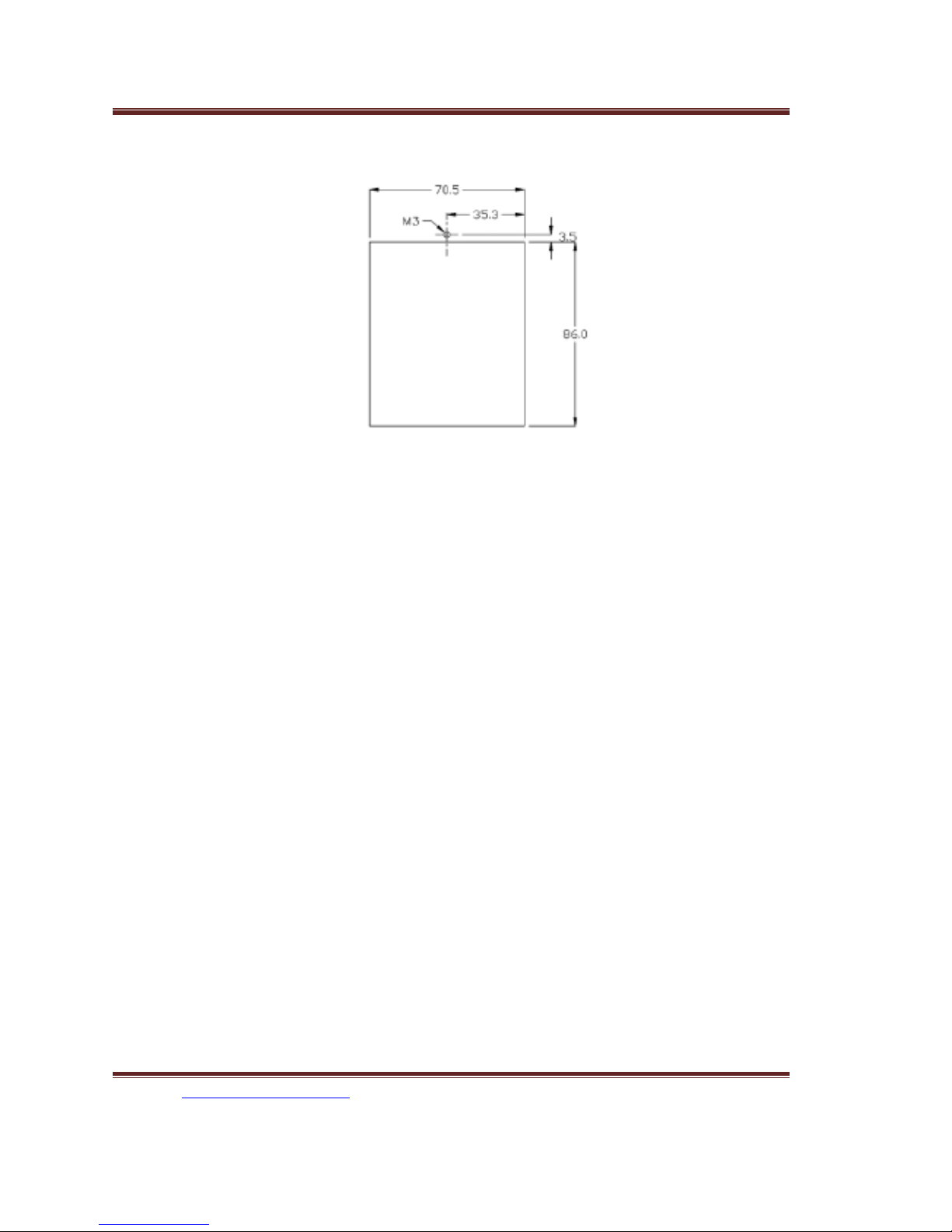
C. Outline Dimension:
10cm min
2
CT2002ES-A75、CT2002ES-1A5、CT2004ES-A75、CT2004ES-1A5
CT2002ES-2A2、CT2002ES-3A7、CT2004ES-2A2、CT2004ES-3A7
Website: www.viet-trung.com.vn Đ/c: 194- Nguyễn Trãi- Võ Cường-TP.Bắc Ninh
3
C.TY TNHH TỰ ĐỘNG HÓA VIỆT TRUNG 02413.281.181-
3. Application notes
A. Concerning the inverter unit:
(1) Do not fit capacitors to the output side of the inverter in order to improve the
power ratio.
(2) In case of fitting MC between inverter and motor to control motor operation,
then the capacity of inverter must be 6 times the capacity of motor.
(3) Run a motor that is within the capacity of the inverter unit, light load current and
no-load current will cause the motor to develop ripple current.
(4) This unit is provided with a current limiting function. The starting torque is
assumed to be from 80% to 100%.
B. Concerning the AC motor
(1) When general-purpose motors are operated at low speeds, there is a reduced
cooling effect, please apply the special purpose motor.
(2) Operation at frequencies exceeding 60 Hz requires caution, as there is the
danger of the mechanical strength failure of the motor.
(3) When motors with brakes are being operated, the power for the brake and
inverter should be taken from the same power supply and the brake operation
must be in phase when the unit is started and stopped.
4. Block diagram, wring
0989.984.666
KEYBAD screw position
3
Website: www.viet-trung.com.vn Đ/c: 194- Nguyễn Trãi- Võ Cường-TP.Bắc
Ninh
4

C.TY TNHH TỰ ĐỘNG HÓA VIỆT TRUNG 02413.281.181-0989.984.666
A. Wiring of main and control circuit
Wire according to the standard connection diagram. On using the external sequence
control, please use small signal relay or double terminal relay to avoid relay terminal
malfunction.
B. Signal circuit
The signal circuit uses either shielded pairs or twisted pairs, should be wired either
using a wiring duct separated from that for the power circuit, or with the wiring
conduit isolated as much as possible.
C. Connecting the power supply and the AC motor
Connect the main circuit, by wiring according to the main circuit terminal connection
diagram. Care is required not to make a mistake when connecting the input and
output terminals, lest it will cause inverter damage. Specifications of main circuit path
CT2002ES-2A2 20 2.0
CT2002ES-3A7 30 3.5
CT2004ES-1A5 10 2.0
CT2004ES-2A2 10 2.0
CT2004ES-3A7 15 3.5
Induction
and NFB are as follow:
Voltage (V) Model NFB (A) Wire size for
circuit (mm2)
CT2002ES-A75 10 2.0
CT2002ES-1A5 15 2.0
220
380
/
460
4
D. Instantaneous current and to improve power ratio, it should be fitted the A.C.L. to R.S.T.
input side under the following circumstance:
a. Where power supply capacity is larger than 500 KVA.
b. Using thyrister, phase advance capacitor etc. from the same power supply.
A.C.L. Specifications table:
Voltage (V) Model Current
(Ar.m.s)
Website: www.viet-trung.com.vn Đ/c: 194- Nguyễn Trãi- Võ Cường-TP.Bắc Ninh
5

C.TY TNHH TỰ ĐỘNG HÓA VIỆT TRUNG 02413.281.181-0989.984.666
Value
220
CT2002ES-A75 6A 1.8mH
CT2002ES-1A5 10A 1.1mH
CT2002ES-2A2 15A 0.71mH
CT2002ES-3A7 20A 0.53mH
380
/
460
CT2004ES-1A5 5A 4.2mH
CT2004ES-2A2 7.5A 3.6mH
CT2004ES-3A7 10A 2.2mH
Notes: The A.C.L. for 220V and 380V/460V have different induction values, please does
not mix up.
E. Brake resistor standard of usage
CT2000ES series inverter contain brake resistor,P、PR terminal can connect external
brake resistor. The sizes of brake resistors take the table for reference.
If inertia is too large or cycle of discharge is higher, user can increase wattage of resistor.
Voltage (V) Type
CT2002ES-A75 120Ω 80W
CT2002ES-1A5
Mark
220
CT2002ES-2A2 60Ω 250W
CT2002ES-3A7
36Ω 400W
380
/
460
CT2004ES-1A5
360Ω 300W
CT2004ES-2A2 250Ω 500W
CT2004ES-3A7 150Ω 800W
Brake resistor
80Ω 160W
standard
Website: www.viet-trung.com.vn Đ/c: 194- Nguyễn Trãi- Võ Cường-TP.Bắc Ninh
6

C.TY TNHH TỰ ĐỘNG HÓA VIỆT TRUNG 02413.281.181-0989.984.666
F. Standard external connection diagram
3-phase power
200V/50Hz
200~230V/50,60Hz
400V/50Hz
400~460V/50,60Hz
ACL
5
(Note: While external is required for DBR, disconnect inter DBR first)
TM
Adaptor
R S T
E
Voltage detect
Current detect
DBR
P PR N
Transformer
Website: www.viet-trung.com.vn Đ/c: 194- Nguyễn Trãi- Võ Cường-TP.Bắc Ninh
U
7

C.TY TNHH TỰ ĐỘNG HÓA VIỆT TRUNG 02413.281.181-0989.984.666
V
External Operation
controller
5K
1/2W
Ω
External signal
Terminal
Terminal Terminal Terminal
4~20mA
IM
W
Reverse operation
Forward operation
10V
IN2
CC
IN1
0V
DI1
DI2
DI3
DI4
RR
FR
COM
Braking control
Website: www.viet-trung.com.vn Đ/c: 194- Nguyễn Trãi- Võ Cường-TP.Bắc Ninh
8

C.TY TNHH TỰ ĐỘNG HÓA VIỆT TRUNG 02413.281.181-0989.984.666
Intreface
CPU Power Control
Operational panel
VOUT CC
D/A output terminal
C1
Multi-function
NO
NC
RJ45
REMOTE
A+ A- B+ B-
Relay
Output terminal
Twisted or shield wires
RS422/485
Series communication interface terminal
Website: www.viet-trung.com.vn Đ/c: 194- Nguyễn Trãi- Võ Cường-TP.Bắc Ninh
9
C.TY TNHH TỰ ĐỘNG HÓA VIỆT TRUNG 02413.281.181-0989.984.666
6
G. Control circuit
Website: www.viet-trung.com.vn Đ/c: 194- Nguyễn Trãi- Võ Cường-TP.Bắc Ninh
10

C.TY TNHH TỰ ĐỘNG HÓA VIỆT TRUNG 02413.281.181-
0989.984.666
7
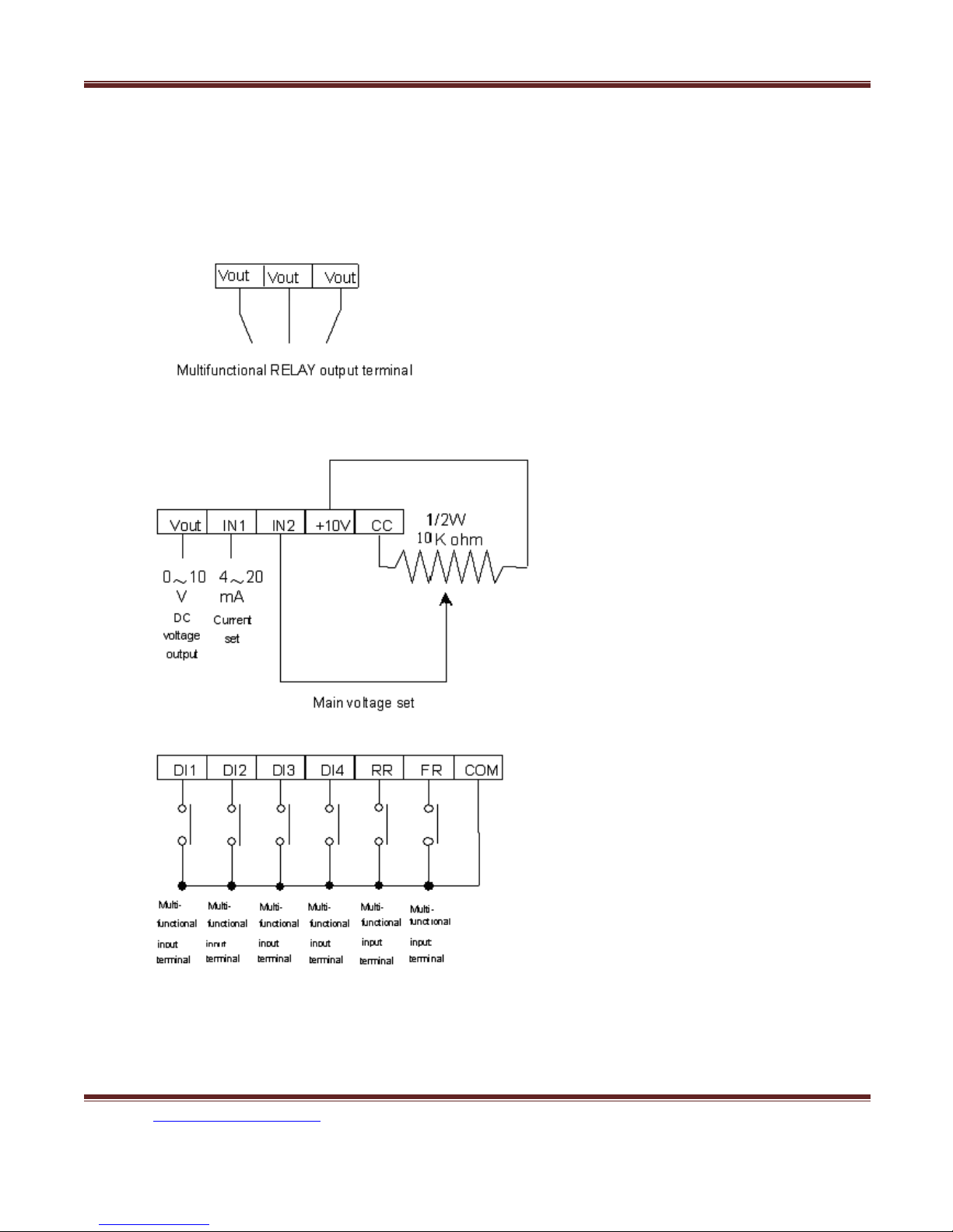
H. Terminal Specifications
Main
Circuit
R.S.T AC power input terminal
U.V.W Inverter output terminal 3-phase induction motor
E Ground terminal Ground terminal of inverter chassis
P.PR Brake resistor connecting terminal
Connected proper brake resistor according to rated ampere
VC Power speed output setting DC +10V
IN1 Current speed input setting DC 4~20mA, CD01=2 or 4
IN2 Voltage speed input setting DC 0~10V/ 5KΩVR, CD01=1,3
VOUT Operation (Frequency /Current)
output indication
Analog Output 0~10V DC, Frequency/Current set by CD54
CC Common input control terminal Ground terminal for speed setting
Control
Terminal
COM Sequence control common terminal
Ground terminal for sequence control
FR Forward operation input terminal Forward operation by FR-COM shorted
RR Reverse operation input terminal Reverse operation by RR-COM shorted
Select 2
Select 2
Multifunctional relay output terminal
NO
(2)
nd
DI1 2
DI2 2
nd
acceleration time mode by shorting 1- COM, set CD10
nd
deceleration time mode by shorting 2- COM, set CD11
DI3 JOG Shorting 3-COM
DI4 RST Shorting 4-COM
C1, NC1, Control output terminal
NO1
acceleration input terminal
nd
deceleration input terminal
Connector capacity AC 220V, 0.1A
Connect 3∮AC with Single∮200-230V/50,60Hz
460V/50,60Hz
Control Terminal (1)
(AC2)
(DC2)
with 3∮380-
Website: www.viet-trung.com.vn Đ/c: 194- Nguyễn Trãi- Võ Cường-TP.Bắc
Ninh
11

C.TY TNHH TỰ ĐỘNG HÓA VIỆT TRUNG 02413.281.181-
0989.984.666
While normal C□closed and NC□Closed
NC
C
Serial communication terminal Refer to Serial Communications User Manual.
While operating C□open and NO□closed
Functions of C1, NC1, NO1 are set by CD47
A+, A- B+, B- SG
SG is 0 volt terminal of the digital signal.
8
5. Operational Test
A. Check before test
Please check the following:
(1) Is wiring correct? Check especially the input and output terminals.
(2) Is there a short-circuit or ground connection on external wiring?
(3) Make sure there is no loosening of screws.
(4) Check external sequence control circuit.
(5) Check voltage of power supply.
B. Operation Method
CT-2000 series inverter unit has both operator panel and external operation
methods.
(1) Operator panel
Website: www.viet-trung.com.vn Đ/c: 194- Nguyễn Trãi- Võ Cường-TP.Bắc Ninh
12

C.TY TNHH TỰ ĐỘNG HÓA VIỆT TRUNG 02413.281.181-
0989.984.666
MCB
CT2000ES
Panel input
(2)External signal operation
C. Operational test
MCB
Switch control
CT2000ES
9
Test according to the following procedure and be aware of indications.
(1) Basic operational test
M
M
Website: www.viet-trung.com.vn Đ/c: 194- Nguyễn Trãi- Võ Cường-TP.Bắc
Ninh
13

C.TY TNHH TỰ ĐỘNG HÓA VIỆT TRUNG 02413.281.181-
0989.984.666
-Operational procedure
I. Connect power supply
II. Monitor glittering indicates frequency
III. Press either FWD or REV key, motor starts running. It will stop accelerating
after reaching set frequency
IV. After pressing STOP key, motor stops and indicating frequency steps down.
The set frequency starts glittering after the motor stops.
V. Repeat procedures III and IV to test forward and reverse operations.
-Operation monitor display
I. With reciprocal glittering indicated HZ LED and factory setting (set VR on
the panel)
II. Hz display, with FWD (or REV) LED lighted up steadily; indication goes up
according to frequency until reaching value 10.00 Hz
III. Indication goes down according to operation frequency, and returns to
situation ” I ” after stop
(2) Frequency change test
- Operational procedure
I. Exercise the above operation test procedures I, II, III
II. Adjust VR on the panel to change frequency command
III. Repeat procedures II to increase or decrease frequency
-Operation monitor display
I. The same as the above basic test of I, II
II. Monitor display indicates the current new setting value
Note:
1. Is motor operation direction correct? (Changing any two of U.V.W output
terminals to change motor operation direction)
2. Is there any noise or vibration on motor?
3. Is it run smoothly during acceleration and deceleration?
4. Is there any power failure?
Website: www.viet-trung.com.vn Đ/c: 194- Nguyễn Trãi- Võ Cường-TP.Bắc Ninh
14

C.TY TNHH TỰ ĐỘNG HÓA VIỆT TRUNG 02413.281.181-
0989.984.666
6. Adjust and Function Specification
A. Keypad operation
FWD
REV
V
Hz
I
10
Display
PROG
SET
FWD
READ
(2) Display specification:
▲
REV
STOP
▼
1.Hz、I LED : Hz LED means of recent revolution frequency.
I LED means of recent revolution current.
Hz and I LED mean of recent revolution voltage on the display.
2.FWD、REV : FWD means motor operate at forward direction.
REV means motor operate at reverse direction.
(3) Keyboard specification:
Website: www.viet-trung.com.vn Đ/c: 194- Nguyễn Trãi- Võ Cường-TP.Bắc Ninh
15

C.TY TNHH TỰ ĐỘNG HÓA VIỆT TRUNG 02413.281.181-0989.984.666
1. FWD and REV: Push keypad to control reverse of motor, and screen display main
display content (Cd02 setting).
Push keypad to control reverse of motor, and screen display main
display content (Cd02 setting).
2.STOP:STOP function: Stop motor revolution when push STOP key, and on the mean
time screen flashing with commanding instruction.
RESET function:While failure occurred, press STOP key to re-start inverter
and save failure in failure memory.
11
3.PROG/SET:FUNC switch: In display mode,PROG/SET key and screen shows Cd00
(General parameter input area).,Press PROG key again and
screen shows CE-00 (failure and engineering mode). If
pressed PROG key now, screen would return to display
mode.
SAVE function: In parameter input mode, press PROG/SET key will save
new parameter just input.
4.READ:READ function:When display shows Cd-?? (General parameter Input mode) or
CE-?? (Failure display and engineering mode), Press
READ to parameter input mode. Screen showing
previously parameter setting. Change of parameter can be
proceeding.
Back to display function:Press READ at parameter input mode can escape
from parameter input mode and not save new parameter.
5. Key (< as shown): SHIFT function:press < key to swich position of nonius,
when the nonius is at left,press <key nonius will be back to
right,when accommodate to press ▼、▲key to modify
parameter in this mode.
6.▼、▲ key: Item of display changing:Press▲, ▼ key at display mode, select required
item.
Parameter selection:Press ▲,▼ key to change value when screen
shows Cd- (General parameter input area) or CE(Failure display and engineering mode). Press and
hold ▲,▼ key can progressively increase or
decrease value.
Parameter modification:Press ▲,▼ key at parameter input mode can
Website: www.viet-trung.com.vn Đ/c: 194- Nguyễn Trãi- Võ Cường-TP.Bắc Ninh
16

C.TY TNHH TỰ ĐỘNG HÓA VIỆT TRUNG 02413.281.181-0989.984.666
change parameter. Using with SET key to
modify parameter.
12
D. Function Code
§
Cd00
Set frequency (Settable range 0.5~240 HZ)
There are 5 methods to change set frequency. Items A~C are methods of panel key
operation, items D-E are methods of external terminal input.
A. At display function, press READ and setting (Cd01=0)
B. Use PROG key to input data (Cd01=0)
C. Set VR on faceplate (Cd01=5)
D. Set external voltage (Cd01=1 or 3)
E. Set external voltage (Cd01=2 or 4)
Note:
Set value should be in accordance with V/F slope (Cd05) and upper limit
1.
frequency (Cd17).
Set by function key
A. At display function, press READ and setting (Cd01=0)
1
0. 0
0
Website: www.viet-trung.com.vn Đ/c: 194- Nguyễn Trãi- Võ Cường-TP.Bắc Ninh
17

C.TY TNHH TỰ ĐỘNG HÓA VIỆT TRUNG 02413.281.181-0989.984.666
READ
1 0. 0 0
1
0. 0 0
1
0. 0 0
▲
1 1. 0 0
Meanwhile the operation speed (Cd00) has been changed but not saved yet (power
cut off and supply again Cd00 still be10.00 ),press PROG/SET and save data.
READ
1 1. 0
B. Use PROG key to input procedure (Cd01=0)
1
0. 0
PROG/
SET
C
d 0 0
READ
1 0. 0 0
1
0. 0 0
0
13
0
Website: www.viet-trung.com.vn Đ/c: 194- Nguyễn Trãi- Võ Cường-TP.Bắc Ninh
18

C.TY TNHH TỰ ĐỘNG HÓA VIỆT TRUNG 02413.281.181-0989.984.666
▲
1 0. 1 0
SET 1 0. 1 0
C
d 0 0
1
0. 1 0
READ
Notice: Indicate 7- segment LED flash.
§ Cd01
The function cannot be modified during revolution.
§ Cd02
The monitor is consisted of four 7-segment LEDs, displays frequency, current and
various data by digital number and character.
Setting procedure of frequency (Selective range 0~6)
Setting procedure of frequency is to select either panel key or external analog signal.
Cd01=0 Set frequency on operation panel, as the above items A-C.
Cd01=1 Set frequency by terminal In2 DC 0~10V/5KΩVR
Cd01=2 Set frequency by terminal In1 DC 4~20mA
Cd01=3 Set frequency by terminal In2 DC 0~10V/5KΩVR hysteresis
Cd01=4 Setting from terminal In1, input DC4~20mA hysteresis
Cd01=5 Setting value input by VR of keypad
Cd01=6 Set frequency by Multi-step function mode
Select Main monitor display (Selective range 0~10)
Cd02=0 Display the frequency, LED HZ active
Cd02=1 Display the current, LED A active
Cd02=2 Display Ultimate speed, Hz and A LED de-active.
C d 0 0
14
Website: www.viet-trung.com.vn Đ/c: 194- Nguyễn Trãi- Võ Cường-TP.Bắc Ninh
19

C.TY TNHH TỰ ĐỘNG HÓA VIỆT TRUNG 02413.281.181-0989.984.666
Cd02=3 Display DC voltage of DC BUS, showing d in front of value
Cd02=4 Display rms value of U.V.W. AC output,LED HZ, A active
Cd02=5 Display external control terminal status, showing E in front of value
Cd02=6 Display temperature rising of PIM module, showing b in front of value
Cd02=7 Display speed feedback. Check if MCK circuit working properly, then the
restart and free run start function (Cd28) will working normally.
Cd02=8 Display current step of multi-step function (step)
Cd02=9 Display current time of multi-step function (minutes)
§ Cd03
Cd02=10 Display motor vibration
Torque mode (Selective range 0~1)
The function cannot be modified during revolution
Cd03=0 Automatic torque compensation de-active, set compensation by Cd07
Cd03=1 Initial Torque boost active,set compensation by Cd52
§ Cd04
The function cannot be modified during revolution
Operation command mode (Selective range 0~2
Set compensation by Cd63
Cd04=0 Operation on operation panel 1 ▲▼key no active
Cd04=1 Operation by external terminal, including FR, RR, terminal (1, 2, 3, 4)
Cd04=2 Operation on operation panel 2 ▲▼key fine tuning frequency
15
.
)
Website: www.viet-trung.com.vn Đ/c: 194- Nguyễn Trãi- Võ Cường-TP.Bắc Ninh
20

C.TY TNHH TỰ ĐỘNG HÓA VIỆT TRUNG 02413.281.181-0989.984.666
§ Cd05
The function cannot be modified during revolution
Set V/F pattern (Selective range 1~14
)
There are 11 patterns of V/F slope, as follow:
V V V V
1 2 3 4
V
V V V
150HZ
60HZ
180HZ
50HZ
200HZ
60HZ
240HZ
50HZ
V
V
F F F F
50HZ
5
60HZ
50HZ
6
100HZ
7
F F F F
9 10
60HZ
8
120HZ
174HZ
103HZ
206HZ
87HZ
F F
When Cd05=11, V/F slope is determined by Cd57, Cd58
Cd05=12 1.5 power curve
Website: www.viet-trung.com.vn Đ/c: 194- Nguyễn Trãi- Võ Cường-TP.Bắc Ninh
21

C.TY TNHH TỰ ĐỘNG HÓA VIỆT TRUNG 02413.281.181-0989.984.666
Cd05=13 1.7 power curve
Cd05=14 square curve
V
F
§
Cd06
Motor current rate (Settable range 25~100)
Set motor overload protective current, in order to avoid motor failure because of
overload. Set value=100, please calculate the following formula:
60HZ
16
Set Value = Motor rated current / Inverter rated current ×100
Ex. Use inverter with 3.7KW(5HP) to drive motor with 2.2KW(3HP)
Inverter rated current = 17.4A
Motor rated current = 8A
§
Website: www.viet-trung.com.vn Đ/c: 194- Nguyễn Trãi- Võ Cường-TP.Bắc Ninh
Set Value = 8 / 17.4 ×100 = 46%
Cd07
The function cannot be modified during revolution.
Torque compensation Vb (Settable range 0~150)
This function is to raise output voltage to increase torque of motor.
It can also be used to increase load slope of low voltage produced by long wiring
between inverter and motor, as well as fluid, fan and pump.
22

C.TY TNHH TỰ ĐỘNG HÓA VIỆT TRUNG 02413.281.181-0989.984.666
Output Voltage
VB
100%
Cd08, 09, 10, 11
§
The time needed for set frequency from 0Hz to 50Hz.
There are 2 selections for each of acceleration time and deceleration time.
To set acceleration/deceleration time
Set Value (T) = (50 - 0) / △F ×T1
T1: time needed for accelerate / decelerate
△F: frequency changed
Ex.: Frequency from 50Hz down to 30Hz, needed time 1 sec. Then:
Set Value (T) = 50 / 50 - 30 ×1 = 2.5
Cd08 = Acceleration time
Cd09 = Deceleration time
Cd10 = 2
Cd11 = 2
Note: The 2
(E.g. Cd04=1)
50%
15%
FS
0%
Acceleration / deceleration time (Settable range 0.1~6000)
Output Frequency (HZ)
nd
Acceleration time
nd
Deceleration time
nd
acceleration/ deceleration time only available on external operation mode.
17
Cd12, 13, 14
§
Speed setting (Settable range 0.5~240)
This function has 4 kinds of speed setting
th
The 2nd, 3rd, 4
terminal 3, 5, the setting value cannot exceed the allowed range.
Cd12 = 2
Cd13 = 3
Cd14 = 4
speeds are set from external terminal FR (or RR) which accommodate
nd
speed setting
rd
speed setting
th
speed setting
Website: www.viet-trung.com.vn Đ/c: 194- Nguyễn Trãi- Võ Cường-TP.Bắc Ninh
23

C.TY TNHH TỰ ĐỘNG HÓA VIỆT TRUNG 02413.281.181-0989.984.666
Note: When apply to multi-speed setting, use external control (e.g. Cd04=1) to start
Cd15
§
and use panel to pre-input to set frequency.
Jogging frequency (Settable range 0.5~30)
To control jogging, use external terminal DI3 accommodate FR or RR with COM shorted.
Set running direction
Set running direction
FR or RR
DI3
Running mode
Jogging
Forward(reverse)
Note: Jogging operation is valid only when operation command selects the
Cd16
§
Note: The most appropriate range for start frequency is 0.5Hz to 10Hz.
§
Cd17
external operation signal mode (e.g. Cd04=1) and Cd59=0 or 1.
Jogging operation procedures:
1. First put in DI3, and then FR(or RR).
2. Put in DI3and FR (or RR) simultaneously.
Be sure always to put in DI3before FR(or RR).
Start frequency (Settable range 0.5~60)
Set motor start frequency
Settable range of frequency from 0.5Hz to 30Hz, accuracy is 0.01Hz.
Frequency
Start
Frequency
Upper limiter of frequency (Selective range 10~240)
Time
18
Website: www.viet-trung.com.vn Đ/c: 194- Nguyễn Trãi- Võ Cường-TP.Bắc Ninh
24
 Loading...