

VIET-TRUNG ALTIVAR 11 User Manual
C.TY TNHH TỰ ĐỘNG HÓA VIỆT TRUNG 02413.281.181-0989.984.666
Website: www.viet-trung.com.vn Đ/c: 194-Nguyễn Trãi-Võ Cường-TP.Bắc
Ninh
1
Instruction
Boletín de
Directives
VVDED302026USR2/03
02/2003
Bulletin
instrucciones d'utilisation
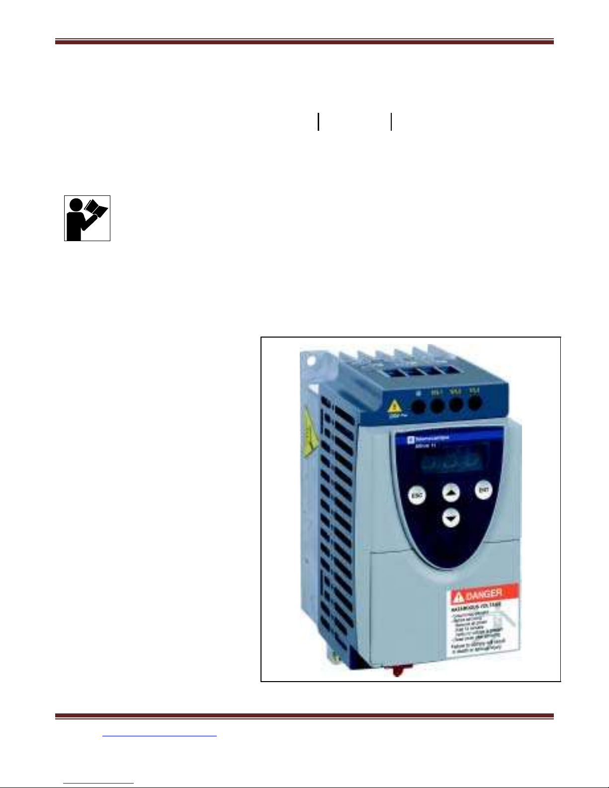
ALTIVAR
®
11
Raleigh, NC, USA
Retain for Future Use.
Conservar para uso futuro.
À conserver pour usage ultérieur.
Adjustable Speed Drive Controllers
User’s Guide
Variadores de velocidad ajustable
Guía del usuario
Variateurs de vitesse
Guide de l’utilisateur

C.TY TNHH TỰ ĐỘNG HÓA VIỆT TRUNG 02413.281.181-0989.984.666
Website: www.viet-trung.com.vn Đ/c: 194-Nguyễn Trãi-Võ Cường-TP.Bắc
Ninh
2

C.TY TNHH TỰ ĐỘNG HÓA VIỆT TRUNG 02413.281.181-0989.984.666
Website: www.viet-trung.com.vn Đ/c: 194-Nguyễn Trãi-Võ Cường-TP.Bắc
Ninh
3

C.TY TNHH TỰ ĐỘNG HÓA VIỆT TRUNG 02413.281.181-0989.984.666
Website: www.viet-trung.com.vn Đ/c: 194-Nguyễn Trãi-Võ Cường-TP.Bắc
Ninh
4
FRANÇAIS
ESPAÑOL
ENGLISH
VVDED302026USR2/03
ALTIVAR® 11 User’s Guide
02/2003
ALTIVAR
®
11 Adjustable Speed Drive Controllers
User’s Guide
Variadores de velocidad ajustable ALTIVAR
®
11
Guía del usuario
Variateurs de vitesse ALTIVAR
®
11
Guide de l’utilisateur

C.TY TNHH TỰ ĐỘNG HÓA VIỆT TRUNG 02413.281.181-0989.984.666
Website: www.viet-trung.com.vn Đ/c: 194-Nguyễn Trãi-Võ Cường-TP.Bắc
Ninh
5
© 2003 Schneider Electric All Rights Reserved
3

C.TY TNHH TỰ ĐỘNG HÓA VIỆT TRUNG 02413.281.181-0989.984.666
Website: www.viet-trung.com.vn Đ/c: 194-Nguyễn Trãi-Võ Cường-TP.Bắc
Ninh
6
ENGLISH
ALTIVAR® 11 User’s Guide
VVDED302026USR2/03
02/2003
HAZARDOUS VOLTAGE
D
ANGER
• Read and understand this manual before installing or operating
the ALTIVAR 11 drive controllers. Installation, adjustment, repair,
and maintenance must be performed by qualified personnel.
• The user is responsible for conforming to all applicable code
requirements with respect to grounding all equipment.
• Many parts in this drive controller, including printed wiring boards,
operate at line voltage. DO NOT TOUCH. Use only electrically
insulated tools.
• DO NOT touch unshielded components or terminal strip screw
connections with voltage present.
• DO NOT short across terminals PA and PC or across the DC
capacitors.
• Install and close all covers before applying power or starting and
stopping the drive controller.
• Before servicing the drive controller:
— Disconnect all power.
— Place a “DO NOT TURN ON” label on the drive controller
disconnect.
— Lock the disconnect in the open position.
• Disconnect all power including external control power that may
be present before servicing the drive controller. WAIT 15
MINUTES for the DC bus capacitors to discharge. Then follow
the DC bus voltage measurement procedure beginning on page
23 to verify that the DC voltage is less than 45 Vdc. The drive
controller LEDs are not accurate indicators of the absence of DC
bus voltage.
Failure to follow this instruction will result in death or serious
injury.

C.TY TNHH TỰ ĐỘNG HÓA VIỆT TRUNG 02413.281.181-0989.984.666
Website: www.viet-trung.com.vn Đ/c: 194-Nguyễn Trãi-Võ Cường-TP.Bắc
Ninh
7
4
© 2003 Schneider Electric All Rights Reserved

C.TY TNHH TỰ ĐỘNG HÓA VIỆT TRUNG 02413.281.181-0989.984.666
Website: www.viet-trung.com.vn Đ/c: 194-Nguyễn Trãi-Võ Cường-TP.Bắc
Ninh
8
ENGLISH
VVDED302026USR2/03
ALTIVAR® 11 User’s Guide
02/2003
Table of Contents
INTRODUCTION . . . . . . . . . . . . . . . . . . . . . . . . . . . . . . . . . . . . . . . . . . . . . . . . . . . . . 7
North American (U) Range (ATV11••••••U) . . . . . . . . . . . . . . . . . . . . . . . . . . . . . . . 7
European (E) Range (ATV11••••••E) . . . . . . . . . . . . . . . . . . . . . . . . . . . . . . . . . . . 7
Asian (A) Range (ATV11••••••A) . . . . . . . . . . . . . . . . . . . . . . . . . . . . . . . . . . . . . . . 7
STORING AND SHIPPING . . . . . . . . . . . . . . . . . . . . . . . . . . . . . . . . . . . . . . . . . . . . . 8
TECHNICAL CHARACTERISTICS . . . . . . . . . . . . . . . . . . . . . . . . . . . . . . . . . . . . . . . 9
DIMENSIONS . . . . . . . . . . . . . . . . . . . . . . . . . . . . . . . . . . . . . . . . . . . . . . . . . . . . . . . 16
MOUNTING AND TEMPERATURE CONDITIONS . . . . . . . . . . . . . . . . . . . . . . . . . . 17
MOUNTING DRIVE CONTROLLERS WITH BASE PLATES . . . . . . . . . . . . . . . . . . 19
MOUNTING THE EMC PLATE . . . . . . . . . . . . . . . . . . . . . . . . . . . . . . . . . . . . . . . . . 20
MOUNTING IN A TYPE 12 OR IP54 METAL ENCLOSURE . . . . . . . . . . . . . . . . . . . 20
Calculating Enclosure Size . . . . . . . . . . . . . . . . . . . . . . . . . . . . . . . . . . . . . . . . . . 20
Ventilation . . . . . . . . . . . . . . . . . . . . . . . . . . . . . . . . . . . . . . . . . . . . . . . . . . . . . . . 22
BUS VOLTAGE MEASUREMENT PROCEDURE . . . . . . . . . . . . . . . . . . . . . . . . . . . 23
ELECTRICAL INSTALLATION . . . . . . . . . . . . . . . . . . . . . . . . . . . . . . . . . . . . . . . . . . 23
POWER TERMINALS . . . . . . . . . . . . . . . . . . . . . . . . . . . . . . . . . . . . . . . . . . . . . . . . 25
RECOMMENDED FUSES . . . . . . . . . . . . . . . . . . . . . . . . . . . . . . . . . . . . . . . . . . . . . 27
CONTROL TERMINALS . . . . . . . . . . . . . . . . . . . . . . . . . . . . . . . . . . . . . . . . . . . . . . 28
WIRING DIAGRAM . . . . . . . . . . . . . . . . . . . . . . . . . . . . . . . . . . . . . . . . . . . . . . . . . . 29
EUROPEAN COMMUNITY EMC DIRECTIVE . . . . . . . . . . . . . . . . . . . . . . . . . . . . . . 30
LOGIC INPUT APPLICATION FUNCTIONS . . . . . . . . . . . . . . . . . . . . . . . . . . . . . . . 32
2-Wire Control . . . . . . . . . . . . . . . . . . . . . . . . . . . . . . . . . . . . . . . . . . . . . . . . . . . . 32
3-Wire Control . . . . . . . . . . . . . . . . . . . . . . . . . . . . . . . . . . . . . . . . . . . . . . . . . . . . 32
Operating Direction (Forward / Reverse) . . . . . . . . . . . . . . . . . . . . . . . . . . . . . . . 32
Preset Speeds . . . . . . . . . . . . . . . . . . . . . . . . . . . . . . . . . . . . . . . . . . . . . . . . . . . 33
Fault Reset . . . . . . . . . . . . . . . . . . . . . . . . . . . . . . . . . . . . . . . . . . . . . . . . . . . . . . 33
Second Ramp . . . . . . . . . . . . . . . . . . . . . . . . . . . . . . . . . . . . . . . . . . . . . . . . . . . . 33
DO OUTPUT APPLICATION FUNCTIONS . . . . . . . . . . . . . . . . . . . . . . . . . . . . . . . . 34

C.TY TNHH TỰ ĐỘNG HÓA VIỆT TRUNG 02413.281.181-0989.984.666
Website: www.viet-trung.com.vn Đ/c: 194-Nguyễn Trãi-Võ Cường-TP.Bắc
Ninh
9
Current in the Motor (AO) . . . . . . . . . . . . . . . . . . . . . . . . . . . . . . . . . . . . . . . . . . . 34
Motor Frequency (AO) . . . . . . . . . . . . . . . . . . . . . . . . . . . . . . . . . . . . . . . . . . . . . 34
Frequency Threshold Reached (LO) . . . . . . . . . . . . . . . . . . . . . . . . . . . . . . . . . . 34
Reference Reached (LO) . . . . . . . . . . . . . . . . . . . . . . . . . . . . . . . . . . . . . . . . . . . 34
Current Threshold Reached (LO) . . . . . . . . . . . . . . . . . . . . . . . . . . . . . . . . . . . . . 34
DO Output Wiring Diagram . . . . . . . . . . . . . . . . . . . . . . . . . . . . . . . . . . . . . . . . . . 35
Configuration of the Analog Input . . . . . . . . . . . . . . . . . . . . . . . . . . . . . . . . . . . . . 35
Wiring Diagram for the Analog Input . . . . . . . . . . . . . . . . . . . . . . . . . . . . . . . . . . . 36
© 2003 Schneider Electric All Rights Reserved
5

C.TY TNHH TỰ ĐỘNG HÓA VIỆT TRUNG 02413.281.181-0989.984.666
Website: www.viet-trung.com.vn Đ/c: 194-Nguyễn Trãi-Võ Cường-TP.Bắc
Ninh
10
ENGLISH
ALTIVAR® 11 User’s Guide
VVDED302026USR2/03
Table of Contents
02/2003
PROGRAMMING . . . . . . . . . . . . . . . . . . . . . . . . . . . . . . . . . . . . . . . . . . . . . . . . . . . . 37
Precautions . . . . . . . . . . . . . . . . . . . . . . . . . . . . . . . . . . . . . . . . . . . . . . . . . . . . . . 37
Programming the Drive Controller: E (European) and U (North American)
Ranges . . . . . . . . . . . . . . . . . . . . . . . . . . . . . . . . . . . . . . . . . . . . . . . . . . . . . . 38
Programming the Drive Controller: A (Asian) Range . . . . . . . . . . . . . . . . . . . . . . 39
ACCESS TO MENUS . . . . . . . . . . . . . . . . . . . . . . . . . . . . . . . . . . . . . . . . . . . . . . . . . 40
FIRST LEVEL ADJUSTMENT PARAMETERS . . . . . . . . . . . . . . . . . . . . . . . . . . . . . 41
drC MOTOR CONTROL MENU . . . . . . . . . . . . . . . . . . . . . . . . . . . . . . . . . . . . . . . . . 43
FUn APPLICATION FUNCTIONS MENU . . . . . . . . . . . . . . . . . . . . . . . . . . . . . . . . . . 45
Incompatible Application Functions . . . . . . . . . . . . . . . . . . . . . . . . . . . . . . . . . . . . 46
tCC Menu . . . . . . . . . . . . . . . . . . . . . . . . . . . . . . . . . . . . . . . . . . . . . . . . . . . . . . . 47
rrS, PS2, and rSF Menus . . . . . . . . . . . . . . . . . . . . . . . . . . . . . . . . . . . . . . . . . . . 48
rP2, StP, and brA Menus . . . . . . . . . . . . . . . . . . . . . . . . . . . . . . . . . . . . . . . . . . . . 50
AdC and SFt Menus . . . . . . . . . . . . . . . . . . . . . . . . . . . . . . . . . . . . . . . . . . . . . . . 51
FLr and dO Menus . . . . . . . . . . . . . . . . . . . . . . . . . . . . . . . . . . . . . . . . . . . . . . . . 53
Atr, LSr, and nPL Menus . . . . . . . . . . . . . . . . . . . . . . . . . . . . . . . . . . . . . . . . . . . . 55
bFr, IPL, SCS, and FCS Menus . . . . . . . . . . . . . . . . . . . . . . . . . . . . . . . . . . . . . . 57
SUP DISPLAY MENU . . . . . . . . . . . . . . . . . . . . . . . . . . . . . . . . . . . . . . . . . . . . . . . . . 58
MAINTENANCE AND TROUBLESHOOTING . . . . . . . . . . . . . . . . . . . . . . . . . . . . . . 59
Precautions . . . . . . . . . . . . . . . . . . . . . . . . . . . . . . . . . . . . . . . . . . . . . . . . . . . . . . 59
Routine Maintenance . . . . . . . . . . . . . . . . . . . . . . . . . . . . . . . . . . . . . . . . . . . . . . 59
Fault Detection . . . . . . . . . . . . . . . . . . . . . . . . . . . . . . . . . . . . . . . . . . . . . . . . . . . 59
Procedure 1: Checking the Supply Voltage . . . . . . . . . . . . . . . . . . . . . . . . . . . . . . 60
Procedure 2: Checking the Peripheral Equipment . . . . . . . . . . . . . . . . . . . . . . . . 60
LIST OF FAULTS AND CORRECTIVE ACTION . . . . . . . . . . . . . . . . . . . . . . . . . . . . 62
Drive Controller Does Not Start, No Fault Displayed . . . . . . . . . . . . . . . . . . . . . . 63
CONFIGURATION AND SETTINGS TABLES . . . . . . . . . . . . . . . . . . . . . . . . . . . . . . 64

C.TY TNHH TỰ ĐỘNG HÓA VIỆT TRUNG 02413.281.181-0989.984.666
Website: www.viet-trung.com.vn Đ/c: 194-Nguyễn Trãi-Võ Cường-TP.Bắc
Ninh
11
6
© 2003 Schneider Electric All Rights Reserved

C.TY TNHH TỰ ĐỘNG HÓA VIỆT TRUNG 02413.281.181-0989.984.666
Website: www.viet-trung.com.vn Đ/c: 194-Nguyễn Trãi-Võ Cường-TP.Bắc
Ninh
12
ENGLISH
VVDED302026USR2/03
ALTIVAR® 11 User’s Guide
02/2003
Introduction
INTRODUCTION
The ALTIVAR 11 (ATV11) family of adjustable speed AC drive
controllers is used for controlling three-phase asynchronous motors.
The controllers range from:
•
0.25 to 3 hp (0.37 to 2.2 kW), 208/230/240 V, single-phase input
•
0.25 to 3 hp (0.37 to 2.2 kW), 208/230/240 V, three-phase input
•
0.25 to 1 hp (0.37 to 0.75 kW), 100/115/120 V, single-phase input
ATV11 controllers have been designed for the global marketplace
with three regional adaptations. Each version of the product has the
same wiring configuration and functionality. The variations among the
regional versions are summarized in the following sections.
North American (U) Range (ATV11••••••U)
•
Designed for the North American market.
•
Current ratings meet or exceed NEC requirements (see
pages 9–11).
European (E) Range (ATV11••••••E)
•
Designed for the European market.
•
Available only in 230 V single-phase input line voltage.
•
Current ratings have been adapted to meet European standards
(see pages 9–11).
•
Has an integrated EMC filter to meet European CE requirements.
Asian (A) Range (ATV11••••••A)
•
Designed for the Asian market.
•
Current ratings have been adapted to meet Asian standards (see

C.TY TNHH TỰ ĐỘNG HÓA VIỆT TRUNG 02413.281.181-0989.984.666
Website: www.viet-trung.com.vn Đ/c: 194-Nguyễn Trãi-Võ Cường-TP.Bắc
Ninh
13
pages 9–11).
•
Speed reference potentiometer and run/stop buttons have been
integrated onto the keypad display for local operation (see pages
39, 47, and 56).
•
Logic inputs can be configured for negative logic (see page 56).
This instruction bulletin covers the technical characteristics,
installation, wiring, programming, and maintenance of all ATV11 drive
controllers.
© 2003 Schneider Electric All Rights Reserved
7
C.TY TNHH TỰ ĐỘNG HÓA VIỆT TRUNG 02413.281.181-0989.984.666
Website: www.viet-trung.com.vn Đ/c: 194-Nguyễn Trãi-Võ Cường-TP.Bắc
Ninh
14
ENGLISH
ALTIVAR® 11 User’s Guide
VVDED302026USR2/03
Storing and Shipping
02/2003
RECEIVING AND PRELIMINARY INSPECTION
Before installing the ATV11 drive controller, read this manual and
follow all precautions.
•
Before removing the drive controller from its packaging, verify that
the carton was not damaged in shipping. Carton damage usually
indicates improper handling and the potential for device damage.
If any damage is found, notify the carrier and your
Square D/Schneider Electric representative.
•
After removing the drive controller from its packaging, visually
inspect the exterior for shipping damage. If any is found, notify the
carrier and your sales representative. Do not install a damaged
device.
•
Verify that the drive controller nameplate and label conform to the
packing slip and corresponding purchase order.
\
DAMAGED EQUIPMENT
CAUTION
Do not operate or install any drive controller that appears damaged.
Failure to follow this instruction can result in injury or
equipment damage.
STORING AND SHIPPING
If the drive controller is not being immediately installed, store it in a
clean, dry area with an ambient temperature between -25 and +69 °C
(-13 to +156 °F). If the drive controller must be shipped to another
location, use the original shipping carton and packing material to
protect it.

C.TY TNHH TỰ ĐỘNG HÓA VIỆT TRUNG 02413.281.181-0989.984.666
Website: www.viet-trung.com.vn Đ/c: 194-Nguyễn Trãi-Võ Cường-TP.Bắc
Ninh
15
8
© 2003 Schneider Electric All Rights Reserved

C.TY TNHH TỰ ĐỘNG HÓA VIỆT TRUNG 02413.281.181-0989.984.666
Website: www.viet-trung.com.vn Đ/c: 194-Nguyễn Trãi-Võ Cường-TP.Bắc
Ninh
16
ENGLISH
VVDED302026USR2/03
ALTIVAR® 11 User’s Guide
02/2003
Technical Characteristics
TECHNICAL CHARACTERISTICS
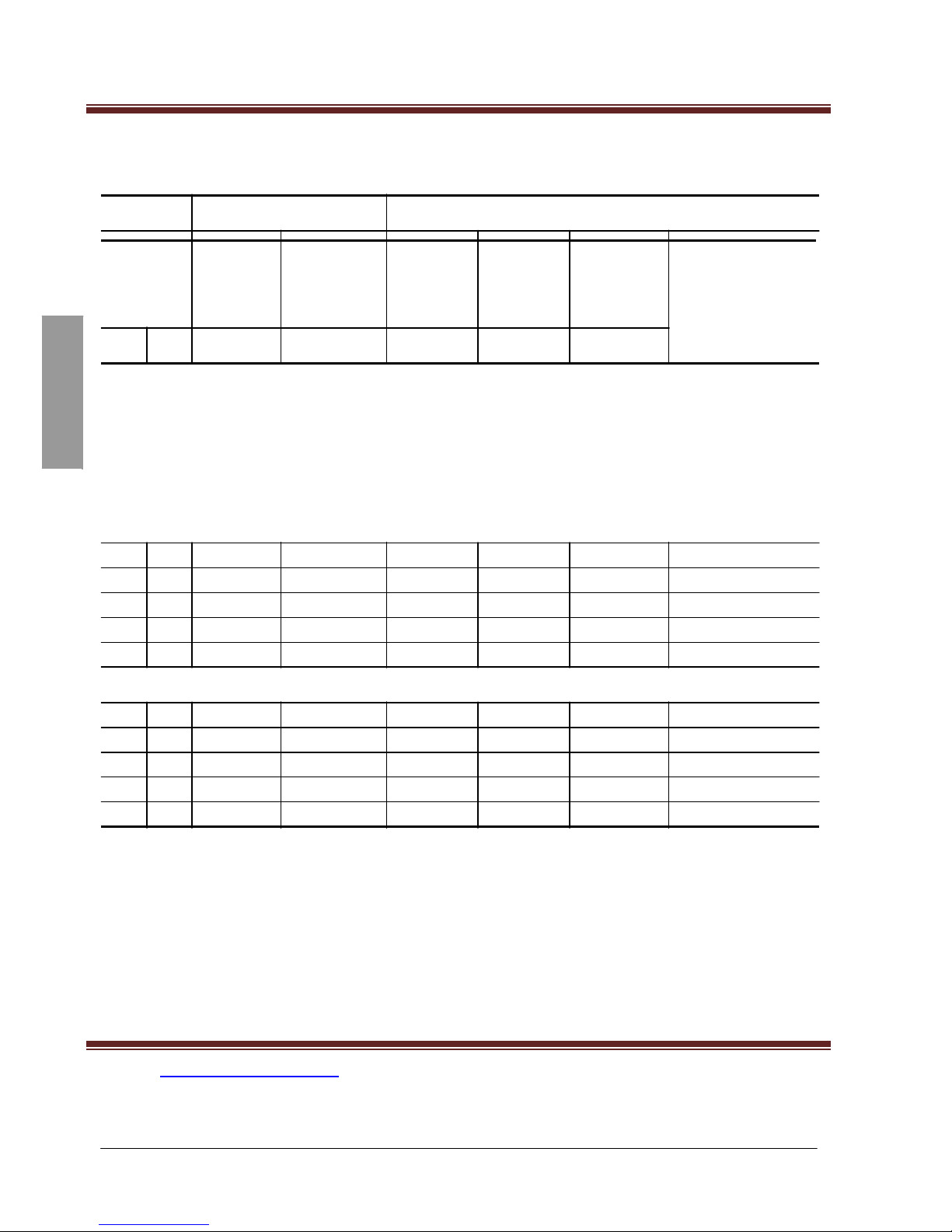
Table 1: Single-Phase Supply Voltage: 200/240 V -15%, +10%, 50/60 Hz;
Three-Phase Output
Motor
Mains
Drive Controller
Motor
Power
1
Input
Line
Current
2
Short Circuit
Rating
Nominal
Current
Max.
Transient
Current
3
Power
Dissipated
at Nominal
Load
Catalog Number
4
kW hp
A
kA
A
A
W
North American (U) Range
0.18 0.25 3.3
1
1.6
2.4
14.5
ATV11HU05M2U
0.37 0.5 6
1
2.4
3.6
23
ATV11•U09M2U
0.75 1
9.9
1
4.6
6.3
43
ATV11•U18M2U
1.5 2
17.1
1
7.5
11.2
77
ATV11HU29M2U
2.2 3
24.1
1
10.6
15
101
ATV11HU41M2U
Asian (A) Range
0.18 0.25 3.3
1
1.4
2.1
14
ATV11HU05M2A
0.37 0.5 6
1
2.4
3.6
25
ATV11•U09M2A
0.75 1
9.9
1
4
6
40
ATV11•U18M2A
1.5 2
17.1
1
7.5
11.2
78
ATV11HU29M2A
2.2 3
24.1
1
10
15
97
ATV11HU41M2A
European (E) Range
0.18 0.25 2.9
1
1.1
1.6
12
ATV11HU05M2E
0.37 0.5 5.3
1
2.1
3.1
20.5
ATV11•U09M2E
0.55 0.75 6.3
1
3
4.5
29
ATV11•U12M2E
0.75 1
8.6
1
3.6
5.4
37
ATV11•U18M2E
1.5 2
14.8
1
6.8
10.2
72
ATV11HU29M2E

C.TY TNHH TỰ ĐỘNG HÓA VIỆT TRUNG 02413.281.181-0989.984.666
Website: www.viet-trung.com.vn Đ/c: 194-Nguyễn Trãi-Võ Cường-TP.Bắc
Ninh
17
2.2 3
20.8
1
9.6
14.4
96
ATV11HU41M2E
1
Power ratings are for a switching frequency of 4 kHz in continuous operation. The switching frequency is
adjustable from 2 to 16 Hz. Above 4 kHz, the drive controller will reduce the switching frequency if an excessive
temperature rise occurs. The temperature rise is sensed by a PTC probe in the power module. Derate the
nominal drive current as follows for continuous operation above 4 kHz: 10% for 8 kHz; 20% for 12 kHz; 30% for
16 kHz.
2
Nominal voltage values: 208 V for the North American (U) Range; 200 V for the Asian (A) Range; 230 V for the
European (E) Range.
3
For 60 seconds.
4
The symbol “•” in a catalog number indicates that the drive controller is available in two versions. For drive
controllers with a heatsink, replace the “•” with an “H” (for example, ATV11HU09M2E). For drive controllers with
a base plate, replace the “•” with a “P” (for example, ATV11PU09M2E).
© 2003 Schneider Electric All Rights Reserved
9
C.TY TNHH TỰ ĐỘNG HÓA VIỆT TRUNG 02413.281.181-0989.984.666
Website: www.viet-trung.com.vn Đ/c: 194-Nguyễn Trãi-Võ Cường-TP.Bắc
Ninh
18
ENGLISH
ALTIVAR® 11 User’s Guide
VVDED302026USR2/03
Technical Characteristics
02/2003
Table 2: Three-Phase Supply Voltage: 200/230 V -15%, +15%, 50/60 Hz;
Three-Phase Output
Motor
Mains
Drive Controller
Motor
Power
1
Input Line
Current
2
Short
Circuit
Rating
Nominal
Current
Max.
Transient
Current
3
Power
Dissipated
at Nominal
Load
Catalog Number
4
kW hp
A
kA
A
A
W
North American (U) Range
0.18
0.25
1.8
5
1.6
2.4
13.5
ATV11HU05M3U
0.37
0.5 3.6
5
2.4
3.6
24
ATV11•U09M3U
0.75
1
6.3
5
4.6
6.3
38
ATV11•U18M3U
1.5 2
11
5
7.5
11.2
75
ATV11HU29M3U
2.2 3
15.2
5
10.6
15
94
ATV11HU41M3U
Asian (A) Range
0.18
0.25
1.8
5
1.4
2.1
13.5
ATV11HU05M3A
0.37
0.5 3.6
5
2.4
3.6
24
ATV11•U09M3A
0.75
1
6.3
5
4
6
38
ATV11•U18M3A
1.5 2
11
5
7.5
11.2
75
ATV11HU29M3A
2.2 3
15.2
5
10
15
94
ATV11HU41M3A
1
Power ratings are for a switching frequency of 4 kHz in continuous operation. The switching frequency is
adjustable from 2 to 16 Hz. Above 4 kHz, the drive controller will reduce the switching frequency if an excessive
temperature rise occurs. The temperature rise is sensed by a PTC probe in the power module. Derate the
nominal drive current as follows for continuous operation above 4 kHz: 10% for 8 kHz; 20% for 12 kHz; 30% for
16 kHz.
2
Nominal voltage values: 208 V for the North American (U) Range; 200 V for the Asian (A) Range.
3
For 60 seconds.
4
The symbol “•” in a catalog number indicates that the drive controller is available in two versions. For drive
controllers with a heatsink, replace the “•” with an “H” (for example, ATV11HU09M3A). For drive controllers with
a base plate, replace the “•” with a “P” (for example, ATV11PU09M3A).

C.TY TNHH TỰ ĐỘNG HÓA VIỆT TRUNG 02413.281.181-0989.984.666
Website: www.viet-trung.com.vn Đ/c: 194-Nguyễn Trãi-Võ Cường-TP.Bắc
Ninh
19
10
© 2003 Schneider Electric All Rights Reserved
C.TY TNHH TỰ ĐỘNG HÓA VIỆT TRUNG 02413.281.181-0989.984.666
Website: www.viet-trung.com.vn Đ/c: 194-Nguyễn Trãi-Võ Cường-TP.Bắc
Ninh
20
ENGLISH
VVDED302026USR2/03
ALTIVAR® 11 User’s Guide
02/2003
Technical Characteristics
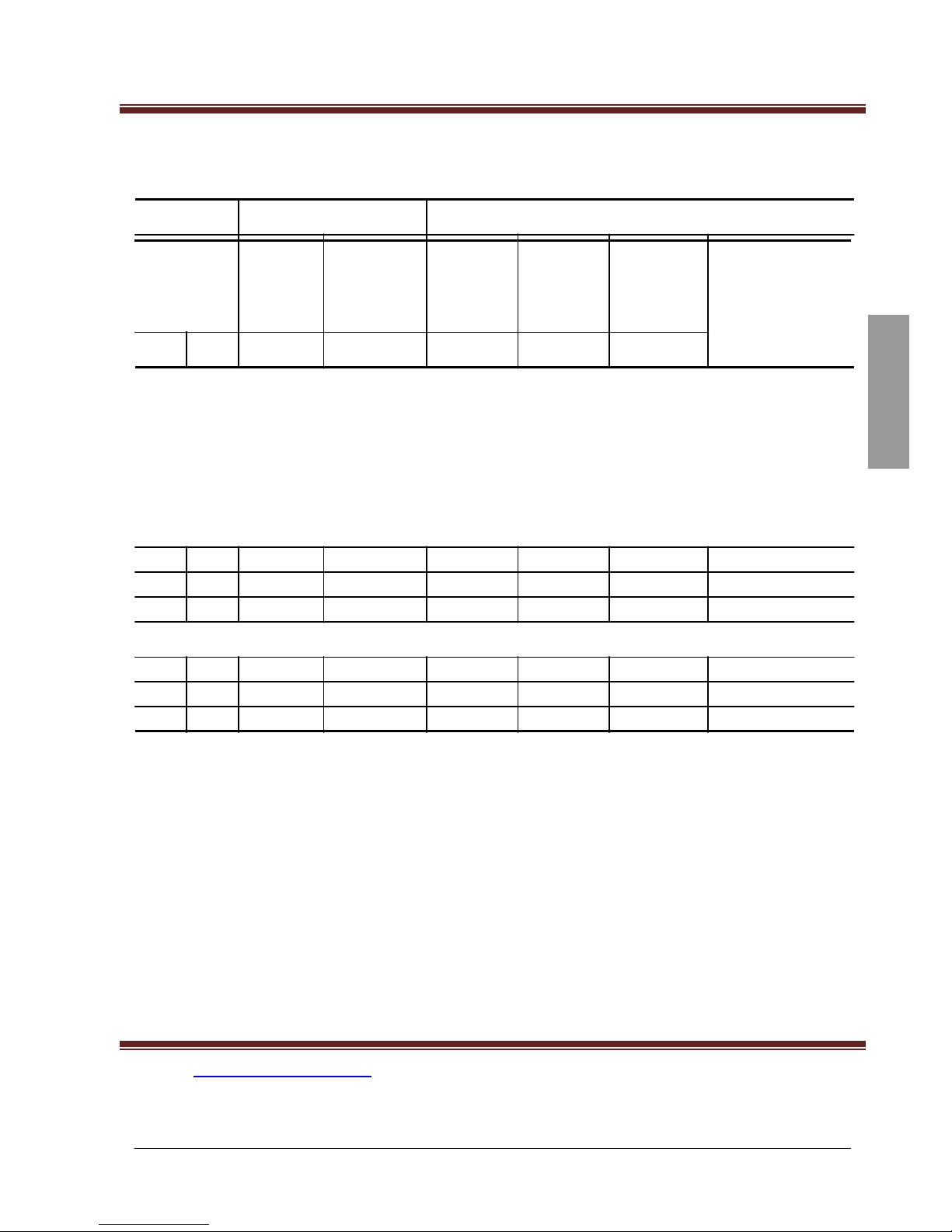
Table 3: Single-Phase Supply Voltage: 100/120 V -15%, +10%, 50/60 Hz;
Three-Phase Output
Motor
Mains
Drive Controller
Motor
Power
1
Input
Line
Current
2
Short
Circuit
Rating
Nominal
Current
Max.
Transient
Current
3
Power
Dissipated
at Nominal
Load
Catalog Number
4
kW hp
A
kA
A
A
W
North American (U) Range
0.18 0.25 6
1
1.6
2.4
14.5
ATV11HU05F1U
0.37 0.5
9
1
2.4
3.6
23
ATV11•U09F1U
0.75 1
18
1
4.6
6.3
43
ATV11HU18F1U
Asian (A) Range
0.18 0.25 6
1
1.4
2.1
14
ATV11HU05F1A
0.37 0.5
9
1
2.4
3.6
25
ATV11•U09F1A
0.75 1
18
1
4
6
40
ATV11HU18F1A
1
Power ratings are for a switching frequency of 4 kHz in continuous operation. The switching frequency is
adjustable from 2 to 16 Hz. Above 4 kHz, the drive controller will reduce the switching frequency if an excessive
temperature rise occurs. The temperature rise is sensed by a PTC probe in the power module. Derate the
nominal drive current as follows for continuous operation above 4 kHz: 10% for 8 kHz; 20% for 12 kHz; 30% for
16 kHz.
2
Values for 100 V nominal voltage.
3
For 60 seconds.
4
The symbol “•” in a catalog number indicates that the drive controller is available in two versions. For drive
controllers with a heatsink, replace the “•” with an “H” (for example, ATV11HU09F1A). For drive controllers with
a base plate, replace the “•” with a “P” (for example, ATV11PU09F1A).

C.TY TNHH TỰ ĐỘNG HÓA VIỆT TRUNG 02413.281.181-0989.984.666
Website: www.viet-trung.com.vn Đ/c: 194-Nguyễn Trãi-Võ Cường-TP.Bắc
Ninh
21
© 2003 Schneider Electric All Rights Reserved
11
C.TY TNHH TỰ ĐỘNG HÓA VIỆT TRUNG 02413.281.181-0989.984.666
Website: www.viet-trung.com.vn Đ/c: 194-Nguyễn Trãi-Võ Cường-TP.Bắc
Ninh
22
ENGLISH
ALTIVAR® 11 User’s Guide
VVDED302026USR2/03
Technical Characteristics
02/2003
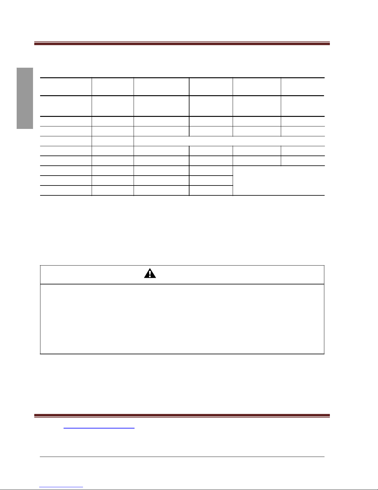
Table 4: Minimum Dynamic Braking Resistance Values For Use with External
Braking Module VW3A11701
230 V
Single-Phase
Controllers
ATV11•••••••
PA/PB
Minimum
Resistance
230 V
Three-Phase
Controllers
ATV11•••••••
PA/PB
Minimum
Resistance
115 V
Single-Phase
Controllers
ATV11•••••••
PA/PB
Minimum
Resistance
HU05M2U, A, E
75
HU05M3U, A
75
HU05F1U, A
75
HU09M2U, A, E
75
HU09M3U, A
75
HU09F1U, A
75
HU12M2E
75
HU18M2U, A, E
75
HU18M3U, A
75
HU18F1U, A
75
HU29M2U, A, E
51
HU29M3U, A
51
PU09F1U
75
HU41M2U, A, E
51
HU41M3U, A
51
PU09M2U
75
PU09M3U
75
PU18M2U
75
PU18M3U
75
WARNING
BRAKING RESISTOR OVERHEATING
• Select the proper braking resistors for the application.
• Provide adequate thermal protection.
• Enclose the braking resistors in an enclosure that is suitable for the environment.
Failure to follow this instruction can result in serious injury or equipment
damage.

C.TY TNHH TỰ ĐỘNG HÓA VIỆT TRUNG 02413.281.181-0989.984.666
Website: www.viet-trung.com.vn Đ/c: 194-Nguyễn Trãi-Võ Cường-TP.Bắc
Ninh
23
12
© 2003 Schneider Electric All Rights Reserved

C.TY TNHH TỰ ĐỘNG HÓA VIỆT TRUNG 02413.281.181-0989.984.666
Website: www.viet-trung.com.vn Đ/c: 194-Nguyễn Trãi-Võ Cường-TP.Bắc
Ninh
24
ENGLISH
VVDED302026USR2/03
ALTIVAR® 11 User’s Guide
02/2003
Technical Characteristics
Table 5: Environmental Specifications
Codes and standards
Electromagnetic
compatibility
Conducted and radiated
emissions for drive
controllers
ATV11 drive controllers have been developed in accordance with IEC and EN, the
strictest international standards and recommendations regarding electrical
equipment for industrial monitoring; specifically, EN 50178 governing
electromagnetic compatibility and conducted and radiated emissions.
•
IEC/EN 61000-4-2 level 3
•
IEC/EN 61000-4-3 level 3
•
IEC/EN 61000-4-4 level 4
•
IEC/EN 61000-4-5 level 3 (power access)
•
IEC/EN 61800-3, environments 1 and 2
All ATV11 controllers:
IEC/EN 61800-3, environments 2 (industrial network) and
1 (public utility network) in limited distribution.
ATV11•U05M2E–U18M2E: EN
55011, EN 55022 Class B, 2: 12 kHz for motor
cables 16 ft. (5 m); and Class A (Group 1), 2: 16 kHz for motor cables 33 ft.
(10 m).
ATV11•U29M2E–U41M2E: EN
55011, EN 55022 Class B, 4: 16 kHz for motor
cables 16 ft. (5 m); and Class A (Group 1), 4: 16 kHz for motor cables 33 ft.
(10 m).
ATV11HU05M2E–HU41M2E:
With additional EMC filter: EN 55011, EN 55022
Class B, 2: 16 kHz for motor cables 66 ft. (20 m); and Class A (Group 1), 2:
16 kHz for motor cables 165 ft. (50 m).
ATV11HU05••U–HU41••U and ATV11HU05••A–HU41••A:
With additional EMC
filter: EN 55011, EN 55022 Class B, 2: 16 kHz for motor cables 16 ft. (5 m); and
Class A (Group 1), 2: 16 kHz for motor cables 66 ft. (20 m).
CE markings
The drive controllers are CE marked on the basis of European directives governing
low voltage (73/23/EEC and 93/68/EEC) and EMC (89/336/EEC).
Agency approvals
UL, CSA, NOM, C-TICK, and CUL
Degree of protection
IP20
Per IEC/EN 60068-2-6:
Vibration resistance
1
•
1.5 mm peak from 3 to 13 Hz
•
1 gn
from 13 to 200 Hz
Shock resistance
15 gn for 11 ms per IEC/EN 60068-2-27
Maximum relative humidity 5–93% non-condensing and without dripping, per IEC 60068-2-3
Storage:
-25 to +69 °C (-13 to +156 °F)

C.TY TNHH TỰ ĐỘNG HÓA VIỆT TRUNG 02413.281.181-0989.984.666
Website: www.viet-trung.com.vn Đ/c: 194-Nguyễn Trãi-Võ Cường-TP.Bắc
Ninh
25
Maximum ambient
temperature
Operating:
-10 to +50 °C (14 to 122 °F) by removing the protective cover from the
top of the drive controller (see page 17). Up to +60 °C, derate the current by 2.2%
for every °C above 50 °C.
Maximum altitude
1000 m (3280 ft.) without derating. Above 1000 m, derate the current by 1% for
each additional 100 m (328 ft.).
1
Drive controller without DIN rail option.
© 2003 Schneider Electric All Rights Reserved
13

C.TY TNHH TỰ ĐỘNG HÓA VIỆT TRUNG 02413.281.181-0989.984.666
Website: www.viet-trung.com.vn Đ/c: 194-Nguyễn Trãi-Võ Cường-TP.Bắc
Ninh
26
ENGLISH
ALTIVAR® 11 User’s Guide
VVDED302026USR2/03
Technical Characteristics
02/2003
Table 6: Drive Characteristics
Output frequency
0–200 Hz
Switching frequency
2–16 kHz
Speed range
1–20
Transient overtorque
150% of rated motor torque
Braking torque
20% of nominal motor torque without dynamic braking (typical value). Up to 150%
with optional dynamic braking module and resistor.
Maximum transient current 150% of rated drive controller current for 60 seconds
Sensorless flux vector control with pulse width modulation (PWM) type motor
Voltage/frequency ratio
control signal.
Factory preset for most constant-torque applications.
Table 7: Electrical Characteristics
Power supply voltage
ATV11•U••M2•:
1-phase, 200 -15% to 240 +10%
ATV11•U••M3•:
3-phase, 200 -15% to 230 +15%
ATV11•U••F1•:
1-phase, 100 -15% to 120 +10%
Power supply frequency 50 Hz ±5% or 60 Hz ±5%
1000 for 1-phase power supply
Power supply AIC rating
Output voltage
Maximum motor cable
length
5000 for 3-phase power supply
Maximum 3-phase voltage equal to:
•
ATV11•U••M2:
the input voltage
•
ATV11•U••F1:
twice the input voltage
•
50 m
(164 ft.) for shielded cable
•
100 m (328 ft.) for non-shielded cable
Verify that the motor is designed for use with AC drive controllers. Cable runs
longer than 12.2 m (40 ft.) may require output filters to reduce voltage spikes at the
motor terminals.
Galvanic isolation
Galvanic isolation between power and control (inputs, outputs, and power supplies)
Protected against short circuits and overloads:
Available internal supplies

C.TY TNHH TỰ ĐỘNG HÓA VIỆT TRUNG 02413.281.181-0989.984.666
Website: www.viet-trung.com.vn Đ/c: 194-Nguyễn Trãi-Võ Cường-TP.Bắc
Ninh
27
Analog input AI1
•
+ 5 V
±5% for speed reference potentiometer (2.2 to 10 k), max. 10 mA
•
+ 15 V ±15% for control inputs, max. 100 mA
1 programmable analog input. Maximum sampling time: 20 ms, resolution 0.4%,
linearity ±5%:
•
Voltage: 0–5 V or 0–10 V, impedance 40 k
•
Current: 0–20 mA or 4–20 mA (without added resistance), impedance 250
14
© 2003 Schneider Electric All Rights Reserved

C.TY TNHH TỰ ĐỘNG HÓA VIỆT TRUNG 02413.281.181-0989.984.666
Website: www.viet-trung.com.vn Đ/c: 194-Nguyễn Trãi-Võ Cường-TP.Bắc
Ninh
28
2
ENGLISH
VVDED302026USR2/03
ALTIVAR® 11 User’s Guide
02/2003
Technical Characteristics
Table 7: Electrical Characteristics (continued)
Logic inputs, LI
Output, DO
Relay outputs
Drive controller protection
4 programmable logic inputs, impedance: 5 k
Power supply: internal 15 V or external 24 V (minimum 11 V, maximum 30 V)
With multiple assignments, several functions can be combined on a single input
(example: LI1 assigned to forward and preset speed 2, LI3 assigned to reverse and
preset speed 3).
Positive logic: state = 0 if < 5 V, state = 1 if > 11 V. Maximum sampling time: 20 ms.
Negative logic: available by programming only in A-range drive controllers.
State = 0 if > 11 V or unwired cable input, state = 1 if < 5 V. Maximum sampling
time: 20 ms.
Factory setting:
•
Pulse width modulation (PWM) type open collector output at 2 kHz. Can be used
on a meter.
•
Maximum current: 10 mA.
•
Impedance: 1 k; linearity: ±
1%; maximum sampling time: 20 ms.
Can be configured as a logic output:
•
Open collector logic output: impedance: 100
, maximum: 50 mA.
•
Internal voltage: see available internal supplies above.
•
External voltage: maximum 30 V, 50 mA.
1 protected relay logic output (contact open if there is a fault). Minimum switching
capacity: 10 mA for 24 Vdc. Maximum switching capacity:
•
On
resistive load (power factor 1 and L/R = 0 ms): 5 A for 250 Vac or 30 Vdc
•
On
inductive load (power factor = 0.4 and L/R = 7 ms): 2 A for 250 Vac or
30 Vdc
•
Thermal protection against overheating via a built-in PTC probe in the power
module
•
Short circuit protection between output phases
•
Overcurrent protection between output and ground phases at power-up only
•
Overvoltage and undervoltage protection
•
Single-phasing protection, in 3-phase
Motor protection
Thermal protection is integrated in the drive controller by I t calculation. Thermal
memory is erased at power-up.
Ground insulation
resistance
>500 M
(galvanic isolation)

C.TY TNHH TỰ ĐỘNG HÓA VIỆT TRUNG 02413.281.181-0989.984.666
Website: www.viet-trung.com.vn Đ/c: 194-Nguyễn Trãi-Võ Cường-TP.Bắc
Ninh
29
Frequency resolution
•
Display 0.1 Hz
•
Analog inputs: 0.1 Hz for maximum 200 Hz
Time constant upon a
change of setpoint
5 ms
© 2003 Schneider Electric All Rights Reserved
15
C.TY TNHH TỰ ĐỘNG HÓA VIỆT TRUNG 02413.281.181-0989.984.666
Website: www.viet-trung.com.vn Đ/c: 194-Nguyễn Trãi-Võ Cường-TP.Bắc
Ninh
30
ENGLISH
=
=
=
=
ALTIVAR® 11 User’s Guide
VVDED302026USR2/03
Dimensions
02/2003
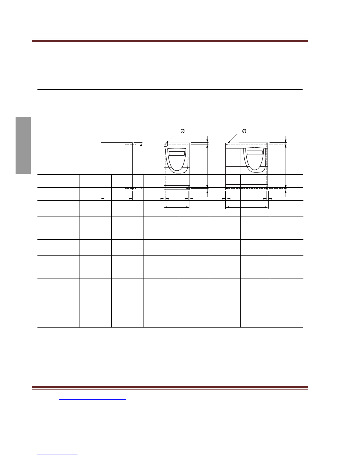
DIMENSIONS
2 4
b H H
c = G = = G =
a a
ATV11U18F1U, U29••U, U41••U
a
b
c
G
H
Ø
Weight
ATV11H••••••
mm
(in.) mm (in.) mm (in.) mm (in.)
mm
(in.)
mm
(in.) kg (lb)
U05••U, E
U05••A
U09••U
U09••E
U09••A
72 (2.835)
72 (2.835)
72 (2.835)
72 (2.835)
72 (2.835)
142 (5.591)
142 (5.591)
142 (5.591)
142 (5.591)
142 (5.591)
101 (3.976)
108 (4.252)
125 (4.921)
125 (4.921)
132 (5.197)
60 (2.362)
60 (2.362)
60 (2.362)
60 (2.362)
60 (2.362)
131 (5.157)
131 (5.157)
131 (5.157)
120 (4.724)
131 (5.157)
2 x 4
(0.157)
0.70 (1.547)
2 x 4
(0.157)
0.85 (1.879)
U12••E
72 (2.835)
142 (5.591)
138 (5.433)
60
(2.362)
120 (4.724)
2 x 4
(0.157)
0.92 (2.033)
U18M•U
U18M2E
U18M•A
72 (2.835)
72 (2.835)
72 (2.835)
147 (5.787)
142 (5.591)
142 (5.591)
138 (5.433)
138 (5.433)
145 (5.709)
60 (2.362)
60 (2.362)
60 (2.362)
131 (5.157)
120 (4.724)
131 (5.157)
2 x 4
(0.157)
0.95 (2.099)
0.92 (2.033)
0.92 (2.033)
U18F1U
U18F1A
U29••U, E
U29••A
U41••U, E
U41••A
117 (4.606)
117 (4.606)
117 (4.606)
117 (4.606)
117 (4.606)
117 (4.606)
142 (5.591)
142 (5.591)
142 (5.591)
142 (5.591)
142 (5.591)
142 (5.591)
156 (6.142)
163 (6.417)
156 (6.142)
163 (6.417)
156 (6.142)
163 (6.417)
106 (4.173) 131 (5.157)
106 (4.173) 131 (5.157)
106 (4.173) 131 (5.157)
106 (4.173) 131 (5.157)
106 (4.173) 131 (5.157)
106 (4.173) 131 (5.157)
4 x 4
(0.157)
1.6 (3.536)
4 x 4
(0.157)
1.6 (3.536)
4 x 4
(0.157)
1.6 (3.536)
 Loading...