

Page 1
Page 2

CONTENTS
CONTENTS 02
SAFETY PRECAUTIONS 03
IMPORTANT INFORMATION 04
CONNECTION TO THE MAINS 05
REMOTE CONTROL INSTALLATION 06
REMOTE CONTROL OPERATIONS 07
FRONT PANEL CONNECTIONS 08
BACK PANEL INTRODUCTIONS 09
BACK PANEL CONNECTIONS 10
TROUBLESHOOTING 11
TECHNICAL DATA 12
02
Page 3
SAFETY PRECAUTIONS
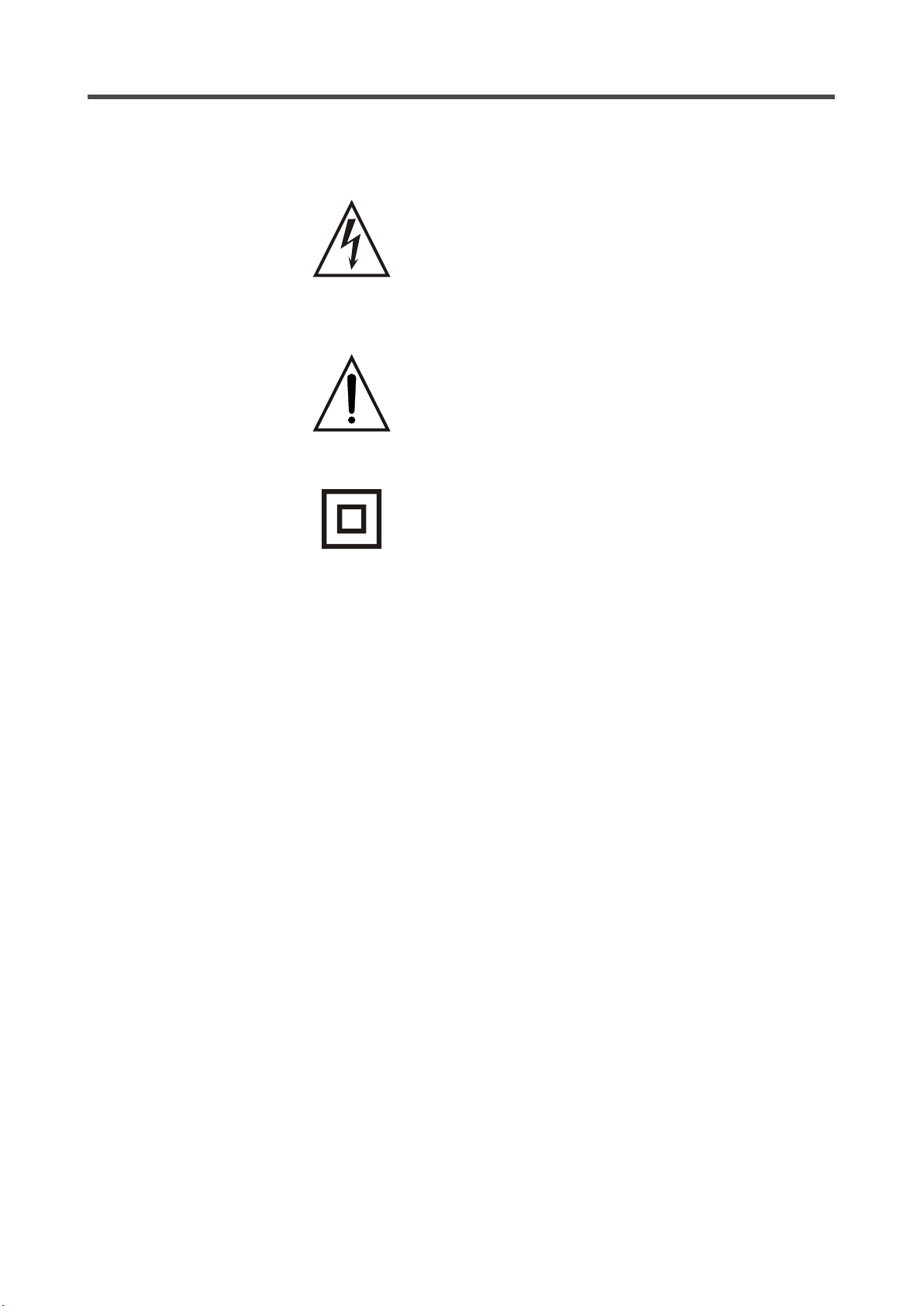
A triangle with a lightning symbol draws the user's
attention to "dangerous voltage" without insulation in the
cabinet which may be high enough to entail a risk of
electric shock.
A triangle with an exclamation mark draws the user's
attention to important instructions for use and
maintenance in the accompanying manual, which should
be studied.
A symbol for CLASS II (double insulation)
WARNING:
CAUTION:
TO MINIMISE THE RISK OF FIRE OR ELECTRICAL SHOCK, DO NOT EXPOSE
THE UNIT TO RAIN OR MOISTURE. DO NOT OPEN THE CABINET AS IT
CONTAINS DANGEROUS VOLTAGE. ONLY QUALIFIED TECHNICIANS ARE
ALLOWED TO CARRY OUT REPAIR AND SERVICE.
if the plug of the power cord needs to be replaced, it is important that the
replacement is identical to the plug to be replaced, or that the new plug has been
recommended by the manufacturer
TO AVOID ELECTRICAL SHOCK, IT IS IMPORTANT TO INSERT THE PLUG
CORRECTLY INTO THE SOCKET.
03
Page 4
IMPORTANT INFORMATION
Handling instructions
- The top and back panel of the unit may become
warm after prolonged use. This is not due to a
defect.
- Turn off the power when the unit is not used.
Protect the power cord
- Follow the instructions below to prevent
abnormal operation, electrical shock, fire or
personal injury:
- Hold the plug firmly when inserting it into the
socket.
- Avoid heat-producing devices.
- Do not place objects on the power cord.
- Do not carry out service work on or change the
power cord.
Positioning
Do not place the unit in any of the fol. places:
- In sunlight, close to heat-producing devices or in
an enclosed rack.
- In places with high temperatures (40C or more)
or high relative humidity (90% or more).
- In dirty places as some internal parts may be
damaged.
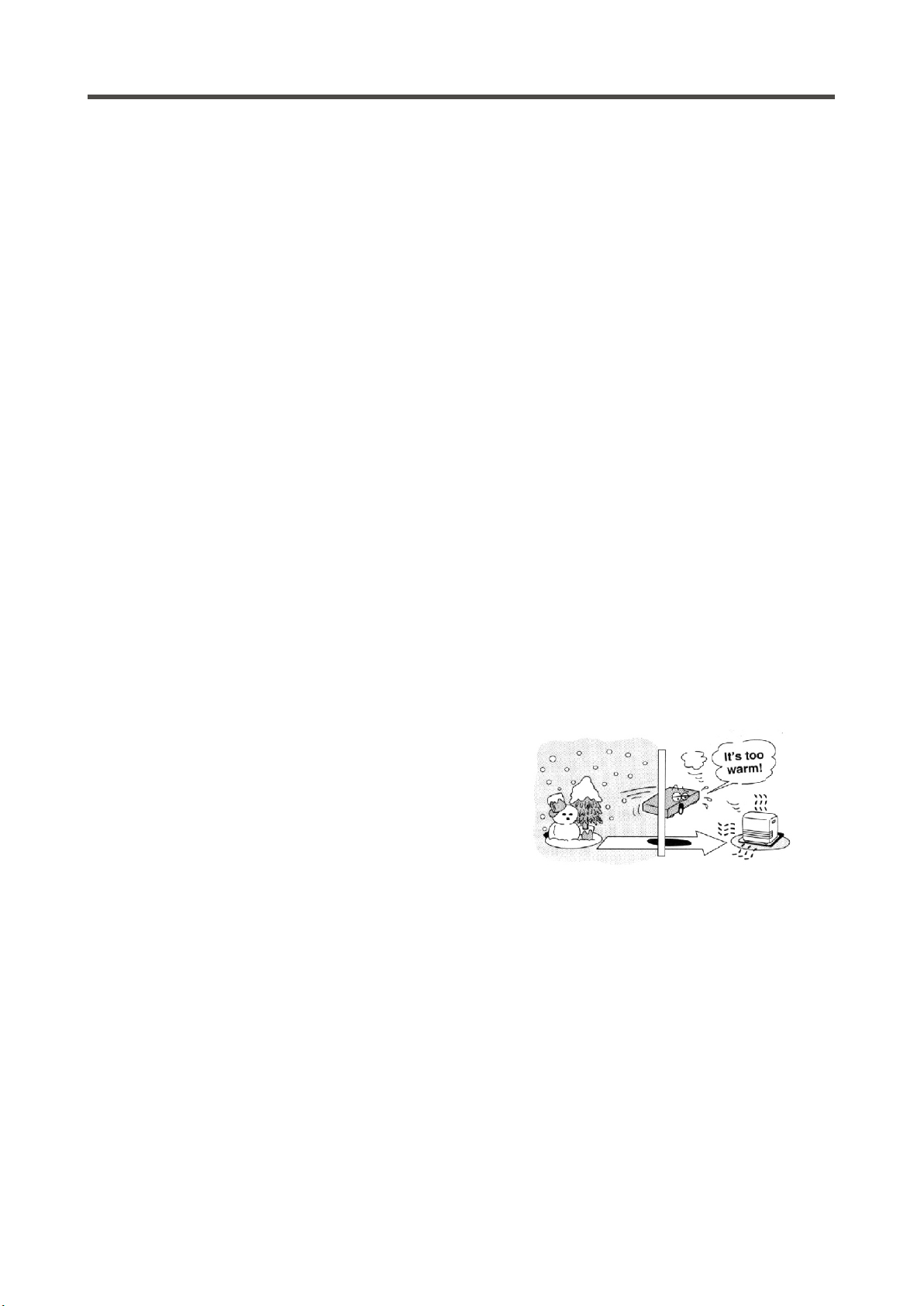
Condensation
Condensation may occur in the following cases:
- When the unit is moved directly from a cold to a
warm place.
- When the unit is used in a room where the
radiator has just been switched on or a place
where the cold air from the air-conditioning
system is directed at the unit.
- If the unit is used in the summer in a warm and
humid room just after it has been moved from an
air-conditioned room.
- If there is steam or a high level of humidity in the
room.
In case of condensation, the unit will not work
properly. Turn off the unit. Unplug the unit and
leave it for 2-3 hours. The unit will then have
adapted to the environment and any
condensation will have disappeared.
Do not put your fingers or any
other objects into the unit
- Touching the internal parts is dangerous and
may cause injury or damage. Do not open the
cabinet.
- Do not place any foreign matter in the unit.
Interference
Placing the unit near a television set, radio or video
player may cause poor picture and sound quality.
In that case, move the unit further away from the
television set, radio or video player.
04
Page 5

CONNECTION TO THE MAINS
Connection to the mains
HAM75 B
150W
220-240V AC~50Hz
USE ONLY WI TH 250V F USE
FUSE :T2A L 25 0V
Do not turn on the power before all connections have been made correctly.
Check that all connections have been made correctly before turning on the
power.
Check that the mains voltage is 220-240V AC50Hz before turning on the power.
Connection to the mains
Check that all other connections have been made correctly before inserting the mains plug into the wall
socket.
Then insert the plug into a suitable socket.
If the unit is to be used abroad, you may need an adapter.
05
Page 6
REMOTE CONTROL INSTALLATION
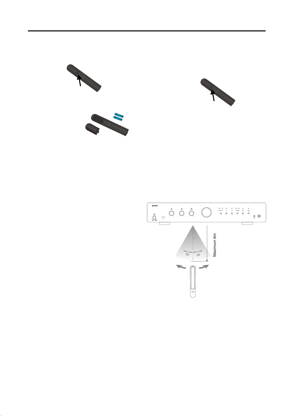
Installation of batteries
1 Remove the cover as illustrated.
2 Position two batteries of the type AAA/R03/UM4
in the battery compartment. Make sure that the
orientation of the batteries is correct (see
drawing at bottom).
- Do not mix new and old batteries and do not use different types of batteries.
- If the remote control is not used for prolonged periods, remove the batteries from the remote control to
avoid corrosion.
3 Replace the cover.
Using the remote control
Direct the remote control at the sensor on the front
panel of the unit. When the remote control signal is
received, the unit reacts accordingly. The remote
control works within a range of 6 metres.
- Sometimes the remote control does not work well in strong light. You may have to move the unit if it is a
problem.
- Malfunction may occur if other remote controls are used near the unit.
- Do not place any objects on the remote control, as the batteries may become flat if a key is depressed
constantly.
- Make sure that there are no obstacles between remote control and unit.
- Do not position the unit behind tinted glass as it may reduce the maximum range of the remote control.
HAM75B
HEADPHONE
06
Page 7
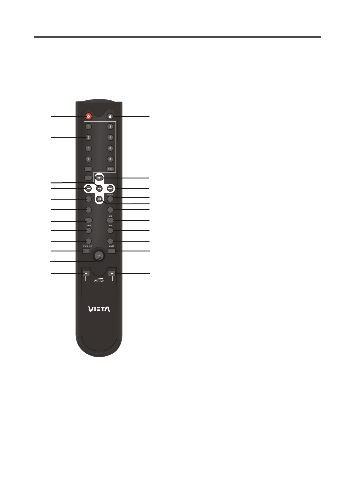
REMOTE CONTROL OPERATIONS
Remote control functions
For HCD30B operations:
1. Power: Set HCD30B, HAM50B/HAM75B into standby.
2. Eject: Open and close the disc tray on CDP-100
1
3
5
7
9
11
13
15
17
19
21
RANDO M
TIME
CD/US B
PHONO
0
STOP
LINE IN
2
3. Number buttons (0,1,2...9 ~+10): selects tracks on
HCD30B.
Note: +10 key could be pressed by 10+(e.g.10, press +10,
button and 0 button; e.g.15, press +10 button
and 5 button to select track 15), and 10x (e.g.25, by 2 times
pressing +10 and 5 button.)
4. Fast forward: Fast forwards in playback on HCD30B
5. Play/Pause:Starts and pause playback.
6. Skip (>>I) / Next: Selects the next track
7. Skip (I<<) / Previous: Select the previous track.
4
8. Repeat: Repeat a single or all tracks on CD disc or USB.
9. Random: All tracks are played in random order.
6
10. Fast reverse: Rewinds in playback on HCD30B.
8
11. TIME: Press the key by times, shows
10
- actual track : elapsed time
12
- actual track : remaining time
- actual track : elapsed time of full disk
14
- actual track : remaining time of full disc
16
12. Stop: Stop playback
18
-----------------------------------------------------------------------------------
20
For HAM50B/HAM75B operations:
22
13. CD/USB: To activate HCD30B and HAM50B/HAM75B, and,
23
switch the CD playback to USB playback;
14. DVD: To activate DVD source.
15. TUNER: To activate Tuner source.
16. AUX: To activate Phono source.
17. PHONO: To activate Phono source.
18. LINE IN: To activate line in source (3.5mm jack in front panel)
19. SPKRS A/B: Speaker selector, to choose pair-A or
pair-B speakers to listen.
Note: there's 4 modes in the speaker selecting button (either in
remote control):
Press 1st time (Default): Drive speaker A;
Press 2nd time: Drive speaker B;
Press 3rd time: Drive speaker A and B both on;
Press 4th time: Drive speaker A and B both off.
...again...
20. Mute: Mutes the sound.
21. Function: Enters the menu on HAM50B/HAM75B, where it
is possible to adjust bass, treble and balance.
22. Volume decrease: Turns down the volume.
23. Volume increase: Turns up the volume.
oppositely switch.
Some of the functions of the unit can only be performed by means of the remote control. Some functions are
connected with the selected signal input source. Some buttons on the remote control may therefore not be
available if the corresponding signal input source has not been selected.
07
Page 8
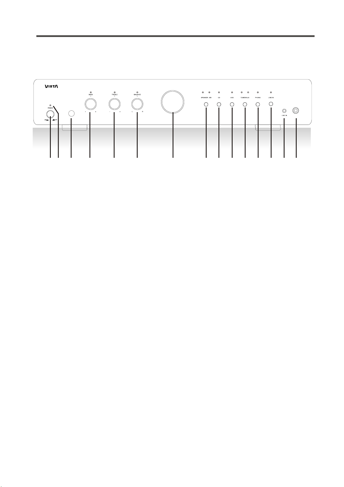
FRONT PANEL CONNECTIONS
Front panel introduction:
HAM75 B
HEADP HONE
1 2
3
4
5
6
7
8 9
10 11 12 141310
1. Mains switch: Used to turn ON/OFF the power.
2. LED .
3.
: Lights off when HAM50B/HAM75B turns on, lights blue when in standby mode
Sensor: For getting the infrared ray signals of remote control operations.
4. Bass: Selects for adjusting the bass (low frequency) up or down.
5. Treble: Selects for adjusting the treble (high frequency) up or down.
6. Balance: Selects for adjusting Right or Left channel of one pair of connected
speakers.
Note: if turn the Right or Left to the end, the other channel will be no sound.
7. Volume knob: Turns up or down the volume.
8. Speaker A/B:
Speaker selector, to choose pair-A or pair-B speakers to listen.
.
Note: there's 4 modes in the speaker selecting button (either in remote control):
Press 1st time (Default): Driver speaker A;
Press 2nd time: Driver speaker B;
Press 3rd time: Driver speaker A and B both on;
Press 4th time: Driver speaker A and B both off.
...again...
9. CD: To activate CD source.
10. DVD: To activate DVD source.
11. TUNER/AUX: Press 1st time to activate TUNER source; press 2nd time to activate
AUX source; ...again...
12. PHONO: To activate PHONO source.
13. LINE IN: To activate LINE IN source.
14. Line in: 3.5mm mini jack source, like MP3 player, iPod, iPhone, etc.
15. Headphone: 6mm jack connector.
08
Page 9
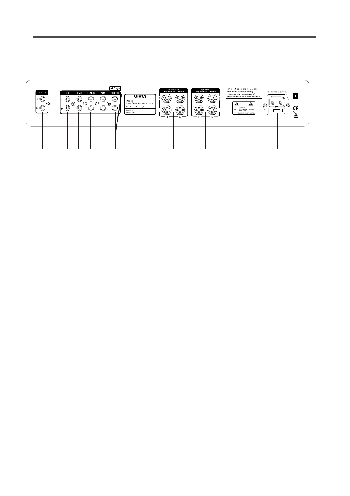
BACK PANEL INTRODUCTIONS
Back panel introductions:
HAM75 B
150W
5 7
1 2
4
1. Line Out: For connection to an external amplifier
2. Input CD: For connection of CD player (recommend HCD30B) or optional equipment.
USE ONLY WI TH 250V F USE
FUSE :T2A L 25 0V
93 6 8
3. Input DVD: For connection of DVD player or optional equipment.
4. Input Tuner: For connection of Tuner or optional equipment
5. Input AUX: For connection of someone optional equipment
6. Input PHONO: For connection of a turntable with an MM phono cartridge
Note: Ground Screw above inputs must be connected meanwhile.
7. Speaker.A Left & Right: For connection to A pair of loudspeakers at 4-8 ohm.
8. Speaker.B Left & Right: For connection to B pair of loudspeakers at 4-8 ohm.
Note: When you want to connect the 2 pairs of Speaker. A&B simultaneously,
the maximum impedance of speakers must be 8 ohm or above.
9. AC Input: For connection of mains voltage.
Speaker Outputs Left and Right
To avoid damage to the amplifier, make sure it is NOT plugged into an AC outlet
while connecting up or disconnecting speaker wire to the speaker outputs. The
amplifier has two pair of speaker outputs on the back labeled Speaker Left and
Speaker Right. Using a suitable speaker wire, connect the right speaker (of
Speaker A or B) to the Speaker Right connectors and the left speaker to the
Speaker Left (of Speaker A or B) . Pay careful attention to match the positive (red)
and negative (black) terminals on your speakers to the positive (red) and negative
(black) terminals on back of the amplifier.
09
Page 10
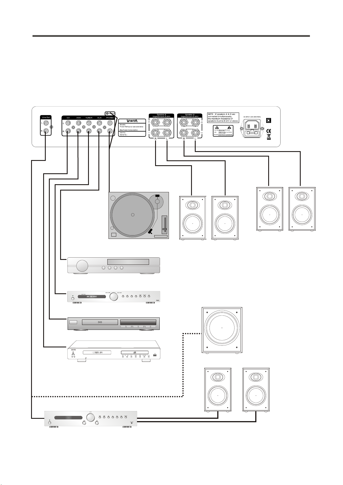
BACK PANEL CONNECTIONS
Back panel connections:
Check that the Power Switch on front of the amplifier is in the off position. Push
the plug (IEC line socket) of the power cable supplied with the amplifier into the
socket (AC INPUT) on back of the unit. Make sure it is pressed in firmly. Plug the
other end of the power cable into an AC wall outlet.
HAM75B
150W
USE ONLY WIT H 250V F USE
FUSE: T2A L 250 V
VCR
DAB/FM Tuner
POWER
DVD Player
CD Player
Turntable
Speaker B
Speaker A
R
R
L
L
Note: When you want to connect the 2
pairs of Speaker. A&B simultaneously,
the maximum impedance of speakers
must be 8 ohm or above.
Powered subwoofer
(Optional)
Slave amplifier
POWER
HCD30B
Speakers
10
Page 11
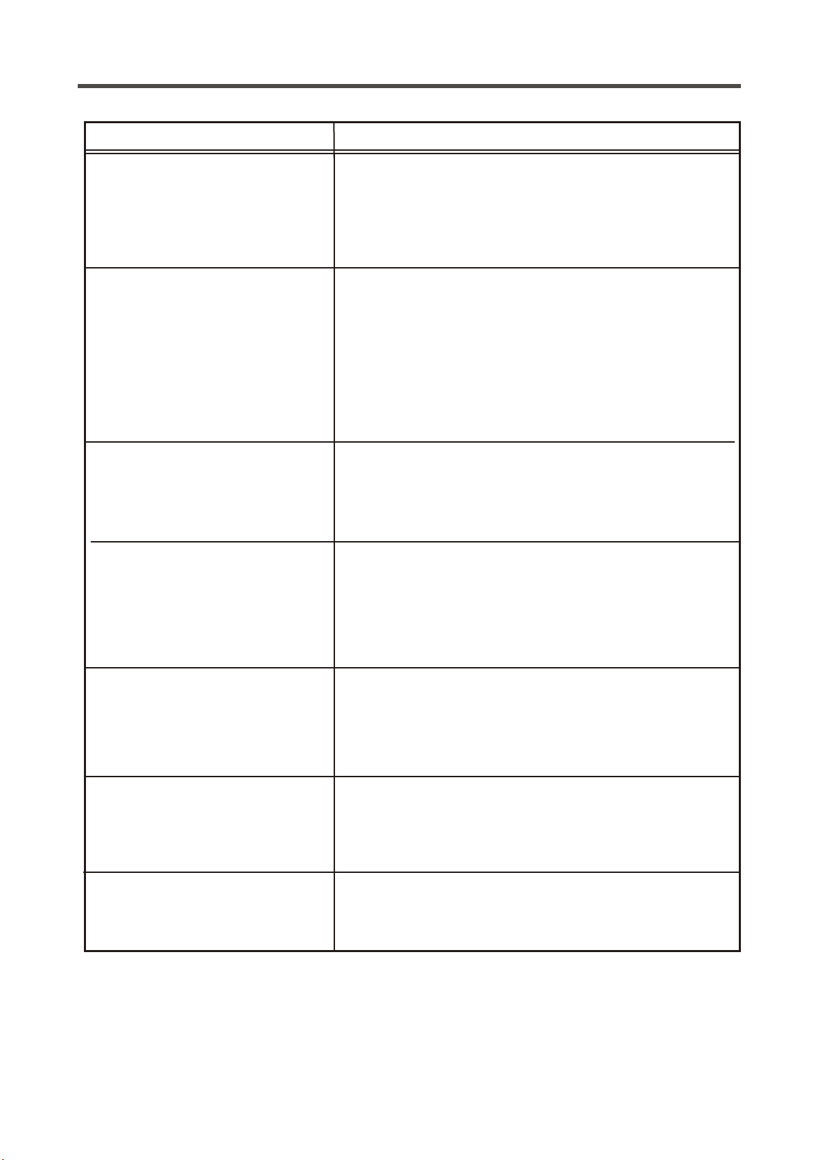
TROUBLESHOOTING
PROBLEM CAUSE/REMEDY
No power when the amplifier is
turned on.
No sound.
There is sound in one channel
only.
High buzzing.
-Switch on the electric current at the socket.
-Check that the plug has been correctly inserted into
the socket.
-The internal fuse has blown and must be replaced
by a qualified service technician.
-The power cord has been damaged and must be
replaced
-The amplifier has not been turned on.
-The volume control is set at a minimum.
-The speaker cables have not been correctly
connected.
-A wrong input source has been selected.
-No input source has been connected.
-The audio input cables or speaker cables
have been incorrectly connected or damaged.
-The input source is defective.
-The speakers are defective.
-The audio input cables have been incorrectly
connected or damaged.
-The ground cable for the record player has not been
connected.
-The record player pick-up is defective.
Weak bass and poor stereo
perspective
Distortion of sound
The unit does not switch
between input modes
-The speaker connection is out of phase. Check that
the positive and negative poles have been correctly
connected, both at the back of the amplifier and at
the back of the speaker.
-Some of the conductor wires of the speaker cable
are in contact with each other which causes
distortion.
-The volume is set too high.
- The amplifier is defective and should be serviced by
a qualified technician.
11
Page 12

TECHNICAL DATA
For HAM50B:
Phono input
Input impedance 47 KOhm
Input sensitivity 10.0 mV
Line level inputs
Input impedance 47 Kohm
Input sensitivity 400mV
Line level outputs
Output impedance Line out 10 KOhm
Headphones 32 Ohm
Maximum output level Line out 250mV
Headphones 2.0 V
Tone control
Treble +/- 14dB
Bass +/- 14dB
For HAM75B:
Phono input
Input impedance 47 KOhm
Input sensitivity 10.0 mV
Line level inputs
Input impedance 47 Kohm
Input sensitivity 500mV
Line level outputs
Output impedance Line out 10 KOhm
Headphones 32 Ohm
Maximum output level Line out 250mV
Headphones 2.0 V
Tone control
Treble +/- 14dB
Bass +/- 14dB
Output power 2 x 30 Watt at 4 Ohm
Frequency response: 10Hz to 80KHz (-3dB)
Distortion: <0.2%
Signal/noise ratio: >80dB
Dimensions: H70 x W430 x D285 mm
Net Weight: 5.7kg
Supplied Accessories:
1. User manual;
2. Mains Lead;
3. Remote Control.
Output power 2 x 50 Watt at 4 Ohm
Frequency response: 10Hz to 80KHz (-3dB)
Distortion: <0.2%
Signal/noise ratio: >80dB
Dimensions: H70 x W430 x D285 mm
Net Weight: 6.3 kg
We reserve the right to change the technical data and the design of the product without notice as a result of
further development.
12
Page 13

Page 14

 Loading...